US8887725B2 - Ventilation interface - Google Patents
Ventilation interfaceDownload PDFInfo
- Publication number
- US8887725B2 US8887725B2US11/430,902US43090206AUS8887725B2US 8887725 B2US8887725 B2US 8887725B2US 43090206 AUS43090206 AUS 43090206AUS 8887725 B2US8887725 B2US 8887725B2
- Authority
- US
- United States
- Prior art keywords
- nasal
- nasal pillow
- spacer
- interface
- flanges
- Prior art date
- Legal status (The legal status is an assumption and is not a legal conclusion. Google has not performed a legal analysis and makes no representation as to the accuracy of the status listed.)
- Active, expires
Links
Images


Classifications
- A—HUMAN NECESSITIES
- A61—MEDICAL OR VETERINARY SCIENCE; HYGIENE
- A61M—DEVICES FOR INTRODUCING MEDIA INTO, OR ONTO, THE BODY; DEVICES FOR TRANSDUCING BODY MEDIA OR FOR TAKING MEDIA FROM THE BODY; DEVICES FOR PRODUCING OR ENDING SLEEP OR STUPOR
- A61M16/00—Devices for influencing the respiratory system of patients by gas treatment, e.g. ventilators; Tracheal tubes
- A61M16/06—Respiratory or anaesthetic masks
- A61M16/0605—Means for improving the adaptation of the mask to the patient
- A61M16/0616—Means for improving the adaptation of the mask to the patient with face sealing means comprising a flap or membrane projecting inwards, such that sealing increases with increasing inhalation gas pressure
- A61M16/0622—Means for improving the adaptation of the mask to the patient with face sealing means comprising a flap or membrane projecting inwards, such that sealing increases with increasing inhalation gas pressure having an underlying cushion
- A—HUMAN NECESSITIES
- A61—MEDICAL OR VETERINARY SCIENCE; HYGIENE
- A61M—DEVICES FOR INTRODUCING MEDIA INTO, OR ONTO, THE BODY; DEVICES FOR TRANSDUCING BODY MEDIA OR FOR TAKING MEDIA FROM THE BODY; DEVICES FOR PRODUCING OR ENDING SLEEP OR STUPOR
- A61M16/00—Devices for influencing the respiratory system of patients by gas treatment, e.g. ventilators; Tracheal tubes
- A61M16/06—Respiratory or anaesthetic masks
- A61M16/0605—Means for improving the adaptation of the mask to the patient
- A61M16/0611—Means for improving the adaptation of the mask to the patient with a gusset portion
- A—HUMAN NECESSITIES
- A61—MEDICAL OR VETERINARY SCIENCE; HYGIENE
- A61M—DEVICES FOR INTRODUCING MEDIA INTO, OR ONTO, THE BODY; DEVICES FOR TRANSDUCING BODY MEDIA OR FOR TAKING MEDIA FROM THE BODY; DEVICES FOR PRODUCING OR ENDING SLEEP OR STUPOR
- A61M16/00—Devices for influencing the respiratory system of patients by gas treatment, e.g. ventilators; Tracheal tubes
- A61M16/06—Respiratory or anaesthetic masks
- A61M16/0666—Nasal cannulas or tubing
- A—HUMAN NECESSITIES
- A61—MEDICAL OR VETERINARY SCIENCE; HYGIENE
- A61M—DEVICES FOR INTRODUCING MEDIA INTO, OR ONTO, THE BODY; DEVICES FOR TRANSDUCING BODY MEDIA OR FOR TAKING MEDIA FROM THE BODY; DEVICES FOR PRODUCING OR ENDING SLEEP OR STUPOR
- A61M16/00—Devices for influencing the respiratory system of patients by gas treatment, e.g. ventilators; Tracheal tubes
- A61M16/06—Respiratory or anaesthetic masks
- A61M16/0683—Holding devices therefor
- A61M16/0694—Chin straps
- A—HUMAN NECESSITIES
- A61—MEDICAL OR VETERINARY SCIENCE; HYGIENE
- A61M—DEVICES FOR INTRODUCING MEDIA INTO, OR ONTO, THE BODY; DEVICES FOR TRANSDUCING BODY MEDIA OR FOR TAKING MEDIA FROM THE BODY; DEVICES FOR PRODUCING OR ENDING SLEEP OR STUPOR
- A61M16/00—Devices for influencing the respiratory system of patients by gas treatment, e.g. ventilators; Tracheal tubes
- A61M16/08—Bellows; Connecting tubes ; Water traps; Patient circuits
- A61M16/0816—Joints or connectors
- A—HUMAN NECESSITIES
- A61—MEDICAL OR VETERINARY SCIENCE; HYGIENE
- A61M—DEVICES FOR INTRODUCING MEDIA INTO, OR ONTO, THE BODY; DEVICES FOR TRANSDUCING BODY MEDIA OR FOR TAKING MEDIA FROM THE BODY; DEVICES FOR PRODUCING OR ENDING SLEEP OR STUPOR
- A61M16/00—Devices for influencing the respiratory system of patients by gas treatment, e.g. ventilators; Tracheal tubes
- A61M16/20—Valves specially adapted to medical respiratory devices
- A—HUMAN NECESSITIES
- A61—MEDICAL OR VETERINARY SCIENCE; HYGIENE
- A61M—DEVICES FOR INTRODUCING MEDIA INTO, OR ONTO, THE BODY; DEVICES FOR TRANSDUCING BODY MEDIA OR FOR TAKING MEDIA FROM THE BODY; DEVICES FOR PRODUCING OR ENDING SLEEP OR STUPOR
- A61M2210/00—Anatomical parts of the body
- A61M2210/06—Head
- A61M2210/0618—Nose
- A—HUMAN NECESSITIES
- A61—MEDICAL OR VETERINARY SCIENCE; HYGIENE
- A61M—DEVICES FOR INTRODUCING MEDIA INTO, OR ONTO, THE BODY; DEVICES FOR TRANSDUCING BODY MEDIA OR FOR TAKING MEDIA FROM THE BODY; DEVICES FOR PRODUCING OR ENDING SLEEP OR STUPOR
- A61M2210/00—Anatomical parts of the body
- A61M2210/06—Head
- A61M2210/0625—Mouth
Definitions
- This inventionrelates generally to the field of respiration or breathing assist masks.
- the inventionrelates to respiration or breathing assist masks utilizing both the nose and mouth.
- Obstructive sleep apnea syndrome(commonly referred to as obstructive sleep apnea, sleep apnea syndrome, and/or sleep apnea) is a medical condition that includes repeated, prolonged episodes of cessation of breathing during sleep.
- the muscles of the upper part of the throat passage of an individualkeep the passage open, thereby permitting an adequate amount of oxygen to flow into the lungs.
- the throat passagetends to narrow due to the relaxation of the muscles. In those individuals having a relatively normal-sized throat passage, the narrowed throat passage remains open enough to permit the adequate amount of oxygen to flow into the lungs.
- the narrowed throat passageprohibits the adequate amount of oxygen from flowing into the lungs.
- a nasal obstructionsuch as a relatively large tongue, and/or certain shapes of the palate and/or the jaw of the individual, further prohibit the adequate amount of oxygen from flowing into the lungs.
- An individual having the above-discussed conditionscan stop breathing for one or more prolonged periods of time (e.g. ten seconds or more).
- the prolonged periods of time during which breathing is stopped, or apneasare generally followed by sudden reflexive attempts to breathe.
- the reflexive attempts to breatheare generally accompanied by a change from a relatively deeper stage of sleep to a relatively lighter stage of sleep.
- the individual suffering from obstructive sleep apnea syndromegenerally experiences fragmented sleep that is not restful.
- the fragmented sleepresults in one or more of excessive and/or inappropriate daytime drowsiness, headache, weight gain or loss, limited attention span, memory loss, poor judgment, personality changes, lethargy, inability to maintain concentration, and/or depression.
- Other medical conditionscan also prevent individuals, including adults and infants, from receiving the adequate amount of oxygen into the lungs.
- individualsincluding adults and infants
- an infant who is born prematurelycan have lungs that are not developed to an extent necessary to receive the adequate amount of oxygen.
- an individualprior to, during and/or subsequent to certain medical procedures and/or medical treatments, an individual can be unable to receive the adequate amount of oxygen.
- oxygen and/or room air containing oxygenis delivered through the mouth and/or nose of the individual.
- CPAPcontinuous positive airway pressure
- BiPAPbi-level positive airway pressure
- IPPVintermittent mechanical positive pressure ventilation
- One conventional ventilation interface for the application of positive pressureincludes a face mask that covers both the nose and the mouth. See, for example, U.S. Pat. No. 4,263,212 to Mizerak and U.S. Pat. No. 6,123,071 to Berthon-Jones et al.
- Other face masksinclude configurations that cover only the nose or only the mouth.
- Standard maskshave air supplied under pressure and use headgear or harnesses configured at least with what is referred to as a lip strap, thereby preventing air from escaping from the user's mouth. Such a strap is positioned level the patient's lips and wasp circumferentially around the patient's head from one side of the mask to the other.
- the force that the harness applied to the mask against the facealso applies an undesirable pressure to the sinus area adjacent to the nose, causing the nasal sinus airways to narrow.
- This narrowingcauses an increase in the velocity of flow through the upper anatomical airways and a decrease in the lateral pressure against the nasal mucosal wall.
- the tubing between the mask and the gas supply unit foldsundesirably, this problem will be exacerbated.
- the above-discussed combination of increased flow velocity and decreased pressureresults in the removal of moisture form the mucosal walls during inspiration and may cause an undesirable drying and a burning sensation within the nares.
- the individualmay remove the mask to alleviate these discomforts, consequently discontinuing the beneficial application of the positive pressure.
- Such increased air flow velocity and decreased pressuredeteriorate the laminar flow between the air input and output portions of the conventional mask.
- VentilatorsA common complaint of a patient regarding ventilation masks is that they cause claustrophobia.
- Such maskshave large headgear that wrap around the entirety of the user's head and cover a significant area of the face including the periphery of both the nose and the mouth. Additionally such masks have a large amount of dead space within the mask where gas can be re-breathed by a patient, and a large area against the face of a user that must be sealed against the mask.
- a respiration assist maskmay include a ventilation interface.
- a cushionmay be connected to the ventilation interface and the cushion may have one or more openings designed to receive one or more inputs.
- the respiration assist maskmay have at least one nasal pillow that may be adjustably coupled to the cushion.
- a method of providing respiration assistancemay include coupling at least one nasal pillow with at least one flange with a cushion having at least one flange. Additionally, the cushion may be coupled to a ventilation interface. Further, breathable gas may be provided to the ventilation interface.
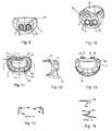
- FIG. 1shows an exploded view of an exemplary embodiment of the invention.
- FIG. 2shows a side perspective view of an exemplary embodiment of the invention.
- FIG. 3shows a front view of an exemplary embodiment of the invention.
- FIG. 4shows a back view of an exemplary embodiment of the invention.
- FIG. 5shows a top view of an exemplary embodiment of the invention.
- FIG. 6shows a bottom view of an exemplary embodiment of the invention.
- FIG. 7shows a right side view of an exemplary embodiment of the invention.
- FIG. 8shows a left side view of an exemplary embodiment of the invention.
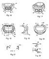
- FIG. 9shows a top-down view of an exemplary embodiment of the invention.
- FIG. 10shows a rotated top-down view of an exemplary embodiment of the invention.
- FIG. 11shows a bottom-up view of an exemplary embodiment of the invention.
- FIG. 12shows a side view of an exemplary embodiment of the invention.
- FIG. 13shows a front view of an exemplary embodiment of the invention.
- FIG. 14shows cut out views of membranes in another exemplary embodiment of the invention.
- FIG. 15shows cut out view of membranes in another exemplary embodiment of the invention.
- FIG. 16shows a top-down view of an exemplary embodiment of the invention.
- FIG. 17shows a rotated top-down view of an exemplary embodiment of the invention.
- FIG. 18shows a bottom-up view of an exemplary embodiment of the invention.
- FIG. 19shows a side view of an exemplary embodiment of the invention.
- FIG. 20shows a front view of an exemplary embodiment of the invention.
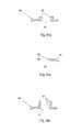
- FIG. 21shows cut out views of membranes in another exemplary embodiment of the invention.
- FIG. 22shows cut out view of membranes in another exemplary embodiment of the invention.
- FIG. 23shows an exemplary view of a pair of nasal pillows
- FIG. 24shows an exemplary rotated view of a pair of nasal pillows.
- FIG. 26shows an exemplary perspective view of a nasal pillow.
- FIG. 27shows an exemplary cross sectional view of a nasal pillow.
- FIG. 28shows an exemplary rotated view of a pair of nasal pillows.
- FIG. 29shows an exemplary top-down view of a nasal pillow.
- FIG. 30shows an exemplary side view of a nasal pillow.
- FIG. 31shows an exemplary bottom-up view of a nasal pillow.
- FIG. 32shows an exemplary side view of a nasal pillow.
- FIG. 33shows an exemplary rotated view of a nasal pillow.
- FIG. 34shows an exemplary view of a pair of nasal pillows.
- FIG. 35shows an exemplary view of a cushioned interface having adjustable nasal pillows.
- FIG. 36shows an exemplary view of a cushion for a ventilation interface.
- FIG. 37shows an exemplary view of a cushion for a ventilation interface having adjustable nasal pillows.
- FIG. 38shows an exemplary view of a cushion for a ventilation interface having adjustable nasal pillows.
- FIG. 39shows an exemplary view of a cushion for a ventilation interface having adjustable nasal pillows.
- FIG. 40shows an exemplary view of a cushion for a ventilation interface having adjustable nasal pillows.
- FIG. 41shows an exemplary view of a ventilation interface having adjustable nasal pillows.
- FIG. 42shows an exemplary view of a ventilation interface having adjustable nasal pillows.
- FIG. 43shows an exemplary view of a ventilation interface having adjustable nasal pillows.
- FIG. 44shows an exemplary view of a ventilation interface having adjustable nasal pillows.
- FIG. 45shown an exemplary view of a ventilation interface having adjustable nasal pillows.
- a ventilation interface maskis disclosed.
- the interfacemay be used for a variety of purposes, for example providing continuous positive airway pressure to a user.
- the ventilation interfacemay alleviate concerns some users have by being small than other types of ventilation masks and by eliminating portions of the mask that fit over the nose of a user. Additionally, by eliminating the portions of a mask that fit over the nose of a user, less sealing is required against the face of a user. Also, the small size of the ventilation interface reduces the amount of space on the interior of the mask, thus resulting in less gas to exhaust and a decreased amount of gas that is breathed more than once.
- FIG. 1shows an exploded view of an exemplary embodiment of a respiration assist mask.
- Respiration assist mask 2may have several separable components, such as ventilation interface 4 , cushioned facial interface 6 , nasal inserts 8 and 9 , and gas supply tube 10 .
- supply tube 10may be connected to ventilation interface 4 in order for input gas may be supplied to the device.
- facial interface 6may be joined with ventilation interface 4 .
- Ventilation interface 4may also accept nasal inserts 8 through receiving holes 12 and 14 .
- the respiration assist mask 2may then be positioned over the mouth of a user such that facial interface 6 forms an airtight seal over the mouth of the user.
- facial interface 6may form a seal against the upper and lower lips of the user.
- respiration assist mask 2When respiration assist mask 2 is positioned over the mouth of a user, the user may insert nasal inserts 8 and 9 into the nares of a user. When nasal inserts 8 and 9 are inserted into the nares of a user, an airtight seal may be formed.
- nasal inserts 8 and 9may be formed in a variety of shapes, for example the volcano style shown in FIG. 1 . Additionally, any size or shape nasal insert that fits into the nares of a user and optionally provides an airtight seal may be used with respiration assist mask 2 .
- Nasal insertsmay be formed from any suitable material, for example silicone.
- nasal inserts 8 and 9may be connected by connector 16 .
- Connector 16may be formed out of any material and is, optionally, formed out of the same material as the nasal inserts. Connector 16 can also be separable from nasal inserts 8 and 9 , or, in a different embodiment, nasal inserts 8 and 9 can be formed without a connector.
- connector 16may function to prevent the rotation of nasal inserts 8 and 9 when they are engaged on facial interface 6 in receiving holes 12 and 14 , respectively. Additionally, connector 16 may act to retain nasal inserts 8 and 9 in a desired position. Alternatively, connector 16 may be removed to allow for rotation of nasal inserts 8 and 9 in receiving holes 12 and 14 , respectively. Further, if connector 16 is removed, two different size nasal inserts may used and attached to respiration assist mask 2 if it is needed or desired by a user.
- nasal inserts 8 and 9may be formed with elliptical distal ends 18 and 20 , respectively. Elliptical ends 18 and 20 may be formed so as to provide comfortable and airtight seals within the nares of a user.
- Connector 16may be positioned on nasal inserts 8 and 9 so as to hold nasal inserts 8 and 9 in a position which provides a comfortable and airtight seal in the nares of the user.
- facial interface 6may provide an airtight seal against the face of a user. Additionally, facial interface 6 may act as a cushion against the face of a user. Similar to the removable cushion disclosed in U.S. Pat. No. 6,595,214 (the '214 patent), which was incorporated by reference into Provisional U.S. Patent Application No. 60/634,188 to which priority is claimed, facial interface 6 may act as a removable cushion that attaches to a ventilation interface. Facial interface 6 may also have gas exit 33 , which may also act to form a seal against an upper and/or lower lip of a user.
- facial interface 6may include chin flap 22 .
- chin flap 22When respiration assist mask 2 is placed on the face of a user, chin flap 22 may be positioned under the chin of the user. In one embodiment, chin flap 22 may provide additional sealing against the face of a user. Additionally, in another embodiment, chin flap 22 may act to provide additional comfort for a user. In a further embodiment, chin flap 22 can act to limit the movement of the lower jaw of a user.
- facial interface 6may have multiple membranes 24 a , 24 b and 24 c (collectively membranes 24 ).
- Membranes 24may serve to provide additional seals against the face of a user.
- membranes 24 , and specifically membrane 24 amay seal against an upper and/or lower lip of a user who is wearing respiration assist mask 2 .
- membrane 24 amay be formed to be thinner than membrane 24 b .
- membrane 24 acan adhere to facial contours and fill small facial gaps as it can be a thin, flexible material.
- membrane 24 bmay be thicker than membrane 24 a to provide auxiliary sealing against the face of a user and provide structural support for the device.
- membrane 24 amay be made of any suitable material, for example silicone, and may be approximately 0.020′′ thick.
- Membrane 24 bmay also be made of any suitable material, for example silicone, and have a thickness of approximately 0.050′′.
- Still other parts of facial interface 6for example 24 c , may have a thickness of approximately 0.100′′. This thickness may extend around the periphery of that portion of the device.
- membranes 24may work in conjunction with chin flap 22 to provide additional sealing capabilities.
- chin flap 22may act to limit the movement of the lower jaw of a user.
- chin flap 22may have some elasticity which allows a user wearing respiration assist mask 2 to move their jaw and, for example, open their mouth.
- membrane 24 awhich also may be elastic, may stretch upper portion of the lower jaw of the user, thus maintaining the seal between the interface and a wearer's face.
- Membrane 24 bwhich may also be elastic, may then stretch against the bottom portion of the mouth of the user, thus maintaining an airtight seal between facial interface 6 and the face of a user.
- chin flap 22allows facial interface 6 to stretch.
- the lower jaw of the userwould move against chin flap 22 , but remain in contact with chin flap 22 as it stretches.
- membranes 24remain sealed against the moving face of the user.
- facial interface 6may have contoured surfaces around receiving holes 12 and 14 . These contoured surfaces may work in conjunction with flange 26 of nasal insert 8 and flange 28 of nasal insert 9 .
- Contoured surface 30 and contoured surface 32may act to hold nasal insert 8 and nasal insert 9 , respectively, in a position that allows for an airtight seal to be formed between the nasal inserts and the nares of a user wearing respiration assist mask 2 .
- contoured surfaces 30 and 32may act to provide an airtight seal between nasal inserts 8 and 9 , respectively and facial interface 6 .
- contoured surfaces 30 and 32can act to angle nasal inserts 8 and 9 , respectively, towards each other and thus orientate them to be better received into the nares of a user.
- auxiliary ports 34 and 36may be positioned on ventilation interface 4 .
- Auxiliary ports 34 and 36may be positioned on an upper portion of interface 4 and may project outwardly. Additionally, when they are not being otherwise utilized, auxiliary ports 34 and 36 may be capped with coverings 38 and 40 , respectively.
- Auxiliary portsmay be used, for example, to connect to outside devices for the purposes of measuring oxygen or carbon dioxide levels, pressure, or to connect to any other outside device to provide measurements, readings or additional inputs.
- auxiliary ports 34 and 36may be utilized as exhaust ports to release gas from the interior portion of ventilation interface 4 .
- Removable coverings 38 and 40may act to prevent the release of gas from respiration assist mask 2 and maintain the airtight seal within the device when.
- Ventilation interface 4may also have a design such that it can accept and seal with cushioned facial interfaces of various sizes.
- cushioned facial interface 6may be made to have different size or shape cushions or have a different sealing area. Different size facial interfaces may maintain a similar size or shape membrane to connect with ventilation interface 4 , however. In other embodiments, different size facial interfaces may be made out of a material that stretches, so as to allow for an airtight seal to be formed between varying sizes of facial interface and ventilation interface 4 .
- FIG. 1also shows input gas tube 10 , which may be formed in an elbow shape or any other shape which may attach to ventilation interface 4 .
- Input gas tubemay be used to deliver any type of gas or aerosol and may be used in any type of respiration application, such as CPAP or BiPAP applications.
- Input gas tube 10may have connection portion 42 which can be used to connect input gas tube 10 to ventilation interface 4 through the use of receiving hole 48 .
- Connection portion 42may be threading, allowing input gas tube 10 to be screwed into receiving hole 48 or any other connection and sealing mechanism, such as a clip or a clasp.
- Input gas tube 10may also have valve 44 disposed on its surface.
- Valve 44may be coupled with a flap, held in place by connector 46 , which is closed in an airtight seal when ventilation gas is being passed through input gas tube 10 . However, if there is no gas being inputted through tube 10 , the flap will open, allowing outside air to enter respiration assist mask 2 .
- the devicemay be worn on the face of a user with any of a variety of types of headgear.
- the headgearmay attach to respiration assist mask 2 through the use of headgear attachment posts 50 .
- Attachment posts 50may be positioned at various portions of ventilation interface 4 , for example at the top and bottom of either side face 4 .
- the headgearmay have female connectors that allow for the headgear to be securely fastened to male attachment posts 50 .
- the headgearmay have looped ends that securely fit around attachment posts 50 .
- any other known type of attachments or postsmay be used to securely attach headgear to respiration assist mask 2 in such as manner as to provide for the comfort of a user and allow for an airtight seal to be formed between the face of a user and respiration assist mask 2 .
- FIG. 2shows another exemplary embodiment where the components of the device are joined together.
- gas input tube 10may be securely connected to ventilation interface 4 through any of the methods mentioned previously. Additionally, tube 10 may be secured to face 4 to provide an airtight seal between the tube and the face, but it may be rotatably engaged to the face. Thus input gas tube 10 may be rotated so that a feed tube that may, optionally, be connected to input gas tube 10 can be mounted in any location or position and continue to supply input gas to respiration assist mask 2 .
- FIG. 2also shows how ventilation interface 4 can be connected to facial interface 6 .
- the mating of these two devicescan create an airtight seal between face 4 and connector 6 .
- any known method of connecting the two componentsmay be utilized, such as tongue in groove, clasps, clips or the like.
- Connector 6may also serve to enhance the structural rigidity of respiration assist mask 2 .
- the top portion and side portions of connector 6may be thicker than other portions of connector 6 . This can allow for stabilization of nasal inserts 8 and 9 when they are joined with connector 6 . Further, this may prevent fore and aft movement as well as lateral movement of nasal inserts 8 and 9 when they are joined with connector 6 , and may also act to enhance the seal between the nasal inserts 8 and 9 and connector 6 .
- nasal inserts 8 and 9are shown connected to facial interface 6 through the use of receiving holes 12 and 14 . This connection may also form an airtight seal between nasal inserts 8 and 9 and facial interface 6 .
- the assembled respiration assist mask 2 shown in FIG. 2may be joined to provide airtight seals between each of the components. Additionally, when the device is positioned on the face of a user, an airtight seal may exist between the interior portion of respiration assist mask 2 and the face of the user.
- exhaust ports 52may be disposed on the face of respiration assist mask 2 .
- a series of exhaust ports 52may be formed on the surface of ventilation interface 4 . These ports 52 may be utilized to release or output carbon dioxide that is exhaled by a user wearing the mask.
- the exhaust portsmay protrude from ventilation interface 4 .
- a different number of exhaust ports that may be larger or smallermay be utilized on ventilation interface 4 .
- one or more exhaust portshave adjustable apertures or adjustable flow rates may be disposed on ventilation interface 4 .
- exhaust ports 52may be capable of being capped or sealed from the interior or exterior of ventilation interface 4 so as to vary the flow rate of exhaust gases.
- exhaust ports 52may be disposed on any location of ventilation interface 4 .
- facial interface 6may have an upper portion that is positioned against the upper lip of a user.
- upper portion 6 a of facial interface 6may rest snugly against the upper lip of a user when respiration assist mask 2 is being worm.
- Upper portion 6 amay act to create an airtight seal between the upper lip of a user wearing the device and connector 6 .
- upper portion 6 amay act as an anchor portion for respiration assist mask 2 when it is being worn by a user.
- upper portion 6 a of connector 6will anchor respiration assist mask 2 on the face of the user to prevent it from being dislodged, which could potentially cause a break in the airtight seal between respiration assist mask 2 and the face of a user.
- upper portion 6 aacts as an anchor, it may prevent forces on chin flap 22 caused by jaw or mouth movement of a user wearing the device from affecting the positioning and sealing of nasal inserts 8 and 9 , which may be inserted into the nares of a user wearing the device.
- stress exerted elsewhere on respiration assist mask 2will not be translated into movement of nasal inserts 8 and 9 within the nares of a user and can prevent the dislodging of the nasal inserts from the nares.
- upper portion 6 amay also prevent movement of nasal inserts 8 and 9 when respiration assist mask 2 is worn or adjusted by a user.
- respiration assist mask 2is worn on the face of a user through the use of headgear attached to posts 50 , the user will likely need or desire to adjust the headgear so as to have comfort while ensuring the device is positioned properly.
- the tightening of headgear on the head of a userwould likely cause articulation and movement apart of the nasal inserts as the device onto which the nasal inserts was mounted stretched as the headgear was tightened.
- upper portion 6 a of connector 6acts as an anchor for respiration assist mask 2 because it is positioned against the upper lip of a wearer to create a seal. Therefore any forces acting upon respiration assist mask 2 by the use or tightening of headgear will be absorbed by upper portion 6 a of connector 6 , rather than by nasal inserts 8 and 9 .
- the comfort of a user wearing the devicecan be enhanced and there is a reduced possibility of nasal inserts 8 and 9 being moved within the nares of a user or dislodged, causing a break in the seal.
- FIG. 5shows a top down view of another embodiment of the invention.
- nasal inserts 8 and 9are shown as being angled towards each other.
- nasal inserts 8 and 9may be angled or orientated differently depending on the fitting required or desired by a user.
- hole 54 on nasal insert 8 and hole 56 on nasal insert 9may be elliptical. Other sizes and shapes of the holes may be utilized depending on the application and wearer of ventilation interface 2 .
- FIG. 6shows a bottom up view of a different embodiment of the invention. This embodiment provides a bottom perspective facial interface 6 and chin flap 22 . Additionally, one example of the placement of attachment posts 50 is shown. FIG. 6 also demonstrates the seal and one possible way of joining facial interface 6 and ventilation interface 4 where facial interface 6 fits into ventilation interface 4 in a tongue-in-groove fashion.
- FIGS. 7 and 8show exemplary side views of the invention.
- chin flap 22 on facial interface 6extends beyond other portions of facial interface 6 .
- interface connectormay have shaped edges which can contour to the face of a user to better provide a seal against the face of the user.
- FIGS. 7 and 8also show auxiliary ports 34 and 36 as being disposed inside recessed or cut out portions of ventilation interface 4 . In other embodiments of the invention, auxiliary ports 34 and 36 may be disposed in an area on ventilation interface 4 that is not cut out or recessed.
- FIGS. 9-22show an exemplary embodiment of cushioned facial interface 6 .
- various membranesare shown as well as the difference between membranes.
- the facial interface shown in FIGS. 9-15may be smaller than the facial interface shown in FIGS. 16-22 .
- bothmay be used interchangeably with ventilation interface 2 and nasal inserts 8 and 9 without any alterations to those devices.
- membrane 24 ais shown as an outer membrane that is thinner than inner membrane 24 b .
- membrane 24 acan be made of any suitable material, such as silicone.
- membrane 24 ais thin so as to be able to follow the contours of a user's face and provide a seal between facial interface 6 and the face of the user. Moreover, the thin membrane may be able to stretch in order to maintain a seal when the user's face moves, for example, such as when the user opens their mouth.
- Membrane 24 bis shown as being thicker than membrane 24 a and is also positioned inside membrane 24 a . Membrane 24 b may also be made out of any suitable material, such as silicone, and, as discussed above, may be thicker to provide support on the inside of mask 2 . Membrane 24 b may also serve to act as a “stop.” In other words, membrane 24 b may limit the amount of movement a user may have while wearing the mask, for example, preventing the user from opening their mouth beyond a certain point.
- the differences in the areas separating various membranescan be seen.
- the distance between membranes 24 a , 24 b and 24 cis larger on axis A-A than it is on the E-E axis.
- the distance between membranes 24 a - c on axis A-Acan allow for increased user comfort and utility, as a seal can be made around the entire mouth of the user. Additionally, by having a seal around the entire mouth area, the structural rigidity of mask 2 can be increased.
- a usermay be able to tighten mask 2 on their face without causing flex in the central or peripheral portions of the mask which could lead to the seal between the user's face and the facial interface being broken.
- This membrane structurecan also allow downward pressure to be exerted on nasal inserts 8 and 9 without dislodging nasal inserts 8 and/or 9 and without significantly deforming facial interface 6 so as to cause a break in the seal between the face of the user and facial interface 6 .
- FIGS. 23-44components of a ventilation interface that may be adjustable in various manners are disclosed.
- FIG. 23An exemplary view of a pair of nasal pillows is shown in FIG. 23 .
- the nasal pillowsmay be a connected pair or, in another exemplary embodiment, may be disposed separately.
- a pair of nasal pillowsis shown as having opening 62 at a distal end of a nasal pillow, as well as nasal insert portion 60 .
- Nasal insert portion 60may flare out from opening 62 so as to provide a comfortable fit against the nares of a user.
- connector 64is shown as coupling a pair of nasal pillows.
- Connector 64may be formed out of any soft or rigid material and may be attachable and detachable from one or both nasal pillows.
- FIG. 24is another exemplary view of a pair of nasal pillows.
- This exemplary embodimentshows flanges 68 , 70 , and 72 , which may be disposed around a perimeter of a nasal pillow.
- Flanges 68 , 70 and 72may be inserted into a cushion associated with a ventilation interface, for example openings 12 and 14 of cushion 6 .
- the nasal pillowsmay be inserted into cushion 6 and provide a gas-tight seal between the cushion and the nasal pillows.
- the nasal pillowsmay be inserted into cushion 6 and form a seal between flange 72 and cushion 6 , flange 70 and cushion 6 or flange 68 and cushion 6 .
- the height of the nasal pillowsmay be varied by a user to obtain a more beneficial height.
- any number of additional flangesmay be disposed on a nasal pillow, in additional to flanges 68 , 70 and 72 , which can allow for a larger degree of adjustment to be obtained. Additionally, the size of the flanges and distance between the flanges may be varied, changed or adjusted, so as to provide additional adjustability.
- indented portion 74 of a nasal pillowis shown.
- Indented portionmay act to compress when a nasal insert is inserted into the nares of a user. This compression may allow for better fitment and comfort of the nasal pillow as well as provide for an additional adjustment of height, depending on how the user inserts nasal insert portion 60 .
- indented portion 74can allow for lateral and fore and aft movement of the nasal pillow. Thus, comfort may be increased and additional adjustments may be made to the fitment of the nasal pillows.
- FIG. 26shows an exemplary view of a single nasal pillow.
- This nasal pillowmay be separated from another nasal pillow through the removal of connector 64 .
- a single nasal pillow of a first sizemay be pair with a second nasal pillow having a second size, thus allowing for additional levels of adjustment to be performed by a user.
- FIG. 27shows an exemplary cross sectional view of a single nasal pillow. From this view, an exemplary orientation of various flanges and grooves may be seen. For example, flanges 68 , 70 and 72 appear in a rotated view as compared to FIG. 24 . Additionally, grooves 66 and 67 may be seen in this cross-sectional view. Grooves 66 and 67 may act to slot into openings 12 and 14 of cushion 6 , for example.
- flanges 68 , 70 and 72may act to provide a gas tight seal between the nasal pillow and cushion 6 and may use friction, or any manner of preventing movement, to hold a nasal pillow in a location or orientation that is desired by a user.
- FIG. 28shows an exemplary rotated view of a pair of nasal inserts.
- indented portion 74may again be compressed or expanded, depending on the fitment desired by a user.
- FIG. 29is an exemplary top-down view of a nasal pillow.
- This viewallows for a view of opening 62 , which may be circular, oval, substantially circular, substantially oval, or any other shape.
- nasal insert portion 60may flare out of the perimeter of opening 62 , allowing for a user to insert the nasal pillow to a desired, function and comfortable depth.
- Nasal insert portion 60may also act to provide a gas tight seal between a nasal pillow and the nares of a user.
- FIG. 31provides an exemplary bottom-up view of a nasal pillow. From this view it is shown that the bottom portion of a nasal pillow may be of a greater area than opening 62 .
- FIGS. 30 , 32 and 33show additional exemplary embodiments of a nasal pillow.
- indented portion 74may be of a different diameter than in previous embodiments. This can allow for different degrees of adjustability, as a thinner indented portion 74 may allow for more fore and aft movement and more lateral movement. Additionally, a thinner indented portion 74 may allow for indented portion 74 to have a higher level of compression.
- FIGS. 32 and 33show another embodiment of a nasal pillow with different sized features. In one exemplary embodiment, opening 82 can be larger or smaller than that in previous embodiments. Additionally, nasal insert portion 84 can have a lesser slope or a greater slope from opening 82 , as well as different surface areas than previous embodiments.
- nasal pillowmay allow for the device to fit in the nares of various-sized nares. Additionally, it can allow for flexibility in using a first nasal pillow with a second nasal pillow, if a user has different sized nares. Additionally, indented portion 80 may also have a larger or smaller diameter than in previous embodiments. This, coupled with other larger or smaller features, may allow for a greater or lesser amount of gas flow through a ventilation interface and into the nares of a user. The gas flow provided to a user may be varied through the use of different sized nasal inserts and nasal pillows depending on the needs of that user.
- FIG. 34different cushions may utilize different amount of flanges.
- opening 88is shown with a singular flange 90 .
- Flange 90may act to receive and seal with a nasal pillow having one or more flanges and which may or may not be adjustable in height.
- multiple flanges 94may act with opening 92 to receive a nasal pillow having one or more flanges.
- Flanges 94can be used to adjust the height of a nasal pillow having a single flange or may be used with a nasal pillow having multiple flanges to provide a greater degree of vertical adjustability.
- Each portion of flanges 94may individually act to couple and seal with a nasal pillow.
- any number of flangesmay be disposed on cushion 86 and may provide for a varying amount of adjustability of a cushion, nasal pillow or spacer.
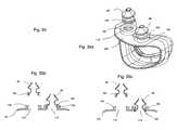
- FIGS. 35 a - cshow yet another exemplary embodiment of a ventilation interface utilizing nasal pillows that may be adjusted.
- nasal pillows 96 and 98may have multiple flanges 100 and 102 , respectively.
- Flanges 100 and 102may be used to couple nasal pillows 96 and 98 , respectively, to cushion 104 .
- Flanges 100 and 102may couple with receiving flanges 106 and 108 , respectively, of cushion 104 .
- Receiving flanges 106 and 108may be disposed on cushion 104 and may include any number of flanges. Additionally, receiving flanges 106 and 108 may be disposed on cushion 104 in any manner, for example molding, adhesion or any other manner known to one having ordinary skill in the art.
- nasal pillow 98is shown as being coupled with cushion 104 through opening 112 .
- nasal pillow 98may be in a raised position from cushion 104 , as the upper flange of flange 108 is used to couple pillow 98 with cushion 104 .
- nasal pillow 98is in a lower position relative to that shown in FIG. 35 b .
- the lower flange of flange 108may be used to couple pillow 98 with cushion 104 .
- any number of flangesmay be disposed on nasal pillows 96 or 98 and any number of receiving flanges 106 and 108 may be disposed on cushion 104 . Therefore, nasal pillows 96 and 98 may be vertically adjusted in a variety of manners and to any height desired by a user of the ventilation interface.
- one or more adjustable nasal pillows 114 and 116may be configured to be disposed on a cushion.
- Each nasal pillow 114 and 116may have a single assembly groove 118 , as shown in FIG. 36A , or multiple assembly grooves 120 , as shown in FIG. 36B .
- Each nasal pillowmay fit into a cushion, which may have one or more flanges for receiving assembly groove 118 or assembly grooves 120 .
- Nasal pillows 114 and 116may also have nasal insert portions 122 and 124 , as well as indented portions 126 and 128 .
- nasal pillows 114 and 116may have openings 130 and 132 , which may be used to deliver breathable gas to the nares of a user.
- nasal pillows 134 and 136may be configured to be attached to cushion 138 .
- Nasal pillows 134 and 136may be inserted into openings 140 and 142 , respectively, on cushion 138 .
- Nasal pillows 134 and 136may include flanges 144 and 146 , respectively, which act to join and seal the nasal pillows with cushion 138 .
- FIGS. 37 b and 37 cshow cross-sectional, views of the exemplary embodiment of FIG. 37 a .
- nasal pillow 134is shown as separated from cushion 138 .
- interior flanges 148are shown inside flange 144 .
- Interior flanges 148may interlock and seal with flanges and grooves 152 that are associated with opening 140 .
- Nasal pillow 136is shown as being joined with cushion 138 .
- Nasal pillow 136may use interior flanges 150 inside flange 146 to interlock and seal with flanges and grooves 154 of opening 142 .
- Nasal pillow 136can be fitted in the lowest fitting position for this combination of flanges and grooves.
- FIG. 35 cshows a further exemplary embodiment having nasal pillow 134 fitted in a low position and nasal pillow 136 fitted in a raised position.
- nasal pillow 134may be coupled with cushion 138 .
- nasal pillow 134may be either permanently or removably coupled with cushion 138 .
- Nasal pillow 134can use interior flanges 148 inside flange 144 to interlock and seal with flanges and grooves 152 of opening 140 .
- Nasal pillow 136can join with cushion 138 in a raised position.
- Nasal pillow 136may use interior flanges 150 inside flange 146 to interlock and seal with upper flanges and grooves 154 of opening 142 .
- Other exemplary embodimentsmay use nasal pillows of varying sizes and may provide additional flanges to allow for different adjustments to be made to the height or orientation of the nasal pillows.
- a spacermay also then be utilized in conjunction with both a nasal pillow and a cushion.
- a pair of nasal pillows, a pair of spacers and a cushionare shown.
- Nasal pillows 156 and 158may be similar to those described in other embodiments and may have one or more flanges, for example 160 and 162 , respectively, disposed on a lower portion of each nasal pillow and allowing for varying degrees of adjustability with respect to cushion 164 .
- Each spacer 166 and 168may have one or more flanges 170 and 172 , respectively.
- Flanges 170 and 172may be disposed at varying locations on spacers 166 and 168 , respectively.
- spacers 166 and 168may be able to join with a nasal pillow and a cushion using flanges 170 and 172 , respectively.
- spacer 166may be separated from nasal pillow 156 and cushion 164 .
- Spacer 168can be either permanently or removably joined with both nasal pillow 158 and cushion 164 .
- nasal pillow 158uses flanges 162 to couple with the upper flanges 172 of spacer 168 .
- a gas tight sealmay be formed between nasal pillow 158 and spacer 168 .
- spacer 168may couple with cushion 164 in opening 176 .
- Lower flanges 172 of spacer 168may be used to couple with the flange disposed at the edges of opening 176 , and a gas tight seal may be provided between the two. Also, the multiple flanges may allow the spacer to fit into the pillow and the cushion at different levels. For example, if a user of a cushion desires to move a pillow away from the cushion, they may utilize a top flange or flanges of a spacer. If a user of a cushion desires to move a pillow away from the cushion, for example, they may utilize a lower flange or flanges of a spacer. In the exemplary embodiment shown in FIG. 38 , the lower portion of flange 172 is not shown as being utilized; thus a user could adjust nasal pillow 158 and spacer 168 vertically using flange 172 of spacer 168 .
- FIG. 39shows another exemplary embodiment of a pair of nasal pillows that are joined to a cushion using spacers. Similar to the embodiment shown in FIG. 38 , nasal pillow 170 is shown in an exploded view and not connected to spacer 166 or cushion 164 . Nasal pillow 172 may again be connected to spacer 168 and cushion 164 . However, in this exemplary embodiment, nasal pillow 172 has been adjusted vertically. Here, the lower portion of flange 176 of nasal pillow 172 can be coupled with the upper portion of flange 172 of spacer 168 , as opposed to the exemplary embodiment shown in FIG. 38 , where both flanges 176 of nasal pillow 172 were coupled to the two upper flanges 172 of spacer 168 . Thus, in the exemplary embodiment shown in FIG. 39 nasal pillow 172 has been adjusted vertically when compared to nasal pillow 172 in FIG. 38 . Additionally, pillow 172 in FIG. 39 may be adjusted in any of a variety of different matters vertically.
- FIG. 40Another exemplary embodiment of an adjustable nasal pillow is shown in FIG. 40 . Similar to FIGS. 37 and 38 , nasal pillow 170 is shown in an exploded view and not connected to spacer 166 or cushion 164 . Nasal pillow 172 may be connected to spacer 168 and cushion 164 . However, in this exemplary embodiment, nasal pillow 172 has again been adjusted vertically. Here, the lower portion of flange 176 of nasal pillow 172 may be coupled with the upper portion of flange 172 of spacer 168 , similar to the exemplary embodiment shown in FIG. 39 . However, in FIG. 40 , the bottom-most portion of flange 172 on spacer 168 can be used to couple spacer 168 to cushion 164 , using opening 176 . Thus, in the exemplary embodiment shown in FIG. 40 nasal pillow 172 has again been adjusted vertically when compared to nasal pillow 172 in FIG. 39 . Additionally, pillow 172 in FIG. 40 may also be adjusted in any of a variety of different matters vertically.
- a spacerused with a nasal pillow, such as 170 or 172 , may have one or more flanges located at varying distances from each other.
- the flangesmay be formed at different distances for different spacers, allowing for variable adjustments to be made to the pillow and cushion.
- the spacermay be formed with one or more flanges or one or more grooves.
- the cushion and pillowmay also be formed with either flanges or grooves, thus allowing for the spacer to be joined in a male-female or female-male fashion with the cushion and pillow.
- Flanges or grooves used with any of the spacer, cushion or pillowmay be formed in any shape, such as square, fully round, partially rounded or any combination thereof.
- the spacersuch as spacer 166 or 168
- the spacermay be formed of any soft material, such as silicone, or any rigid material, such as plastic.
- the spacermay be formed in a variety of shapes and having a variety of flanges or grooves regardless of whether the spacer is formed of any soft or hard material.
- one or more spacersmay be joined or connected to provide further adjustability of a pillow or cushion location.
- an additional spacercould be coupled to nasal pillow 172 and then coupled with spacer 168 .
- any of the embodiments disclosed in this documentmay be used with a single pillow or one or more connected pillows, and a single spacer, one or more connected spacers, or one or more axially connected spacers.
- a pair of nasal pillowsmay be joined with spacers and then coupled with a cushion for a ventilation interface.
- nasal pillows 178 and 180may use flanges 196 and 198 , respectively (and shown as shrouded in FIG. 41 a ) to couple with spacers.
- Spacer 188may couple with flange 196 of nasal pillow 178 using flanges 192 .
- a similar couplingmay occur between nasal pillow 180 and spacer 190 , although they are shown as already coupled in this view, thus flanges 194 are not shown in FIG. 41 a.
- FIG. 41 bshows a side perspective view of the exemplary embodiment of FIG. 41 a .
- spacer 188is substantially round.
- spacer 188may be any shape that may be coupled with nasal pillow 178 and also may be coupled with opening 196 on cushion 186 .
- flanges 192are shown as extending around the entire perimeter of spacer 188 .
- flanges 192may be disposed on only parts of spacer 188 , may be arranged in different locations, may be located at different distances from the other flanges, may be angled or may not extend around the entire perimeter of a spacer. Additionally, as shown in FIGS.
- cushion 186may be configured to adhere to the contours of the face of a user. Cushion 186 may also be configured on one side to receive a ventilation interface, such as a plastic interface having a means for accepting input gas, such as CPAP or BiPAP.
- a ventilation interfacesuch as a plastic interface having a means for accepting input gas, such as CPAP or BiPAP.
- FIG. 41 ca cross-sectional view of the embodiments shown in FIGS. 41 a and 41 b is shown in FIG. 41 c .
- nasal pillow 180can use multiple grooves 198 to receive the upper portion of spacer 190 flange 194 .
- only a lower portion of spacer 190 flange 194may be used in opening 198 to couple spacer 190 to cushion 186 .
- spacers 188 and 190may be adjusted vertically on cushion 186 without disturbing the coupling of spacers 188 and 190 to nasal pillows 178 and 180 , respectively.
- nasal pillows 178 and 180may be adjusted vertically on spacers 188 and 190 , respectively, without disturbing the coupling of spacers 188 and 190 with cushion 186 . Also, in another exemplary embodiment, nasal pillows 178 and 180 may be adjusted vertically on spacers 188 and 190 , respectively, while spacers 188 and 190 are being adjusted on cushion 186 .
- FIG. 42shows another exemplary embodiment of a ventilation interface where nasal pillows may be adjusted through the use of flanges on the nasal pillows, flanges on the cushion and through the use of spacers.
- nasal pillows 204 and 206may be coupled with spacers 214 and 216 , respectively.
- Spacers 214 and 216may also be coupled with cushion 212 .
- Nasal pillows 204 and 206 in FIG. 42may also be adjusted to different positions.
- Nasal pillow 204may use flanges 208 on two upper flanges 218 of spacer 214 .
- Spacer 214may then be coupled to opening 226 of cushion 212 through the use of the upper portion of flange 222 .
- Nasal pillow 206can use the bottom portion of flanges 210 on the uppermost flange of flanges 220 of spacer 216 . Spacer 216 can then be coupled to opening 228 of cushion 212 through the use of the upper portion of flange 224 .
- each of the nasal pillows, spacers and cushionmay be adjusted independently or in conjunction with one another.
- nasal pillow 204could be adjusted vertically on spacer 214 without affecting the positioning of spacer 214 on flange 222 of cushion 212 .
- spacer 214could be adjusted on flanges 218 of cushion 212 without affecting the position of nasal pillow 204 on spacer 214 .
- the position of nasal pillow 204 on spacer 214could be adjusted simultaneously or in conjunction with the position of spacer 214 on cushion 212 .
- nasal pillowsmay be adjusted through the use of a threaded spacer.
- nasal pillows 230 and 232may have flanges 234 and 236 , respectively.
- Flanges 234 and 236may couple with spacers 240 and 242 , respectively.
- Spacers 240 and 242may have threaded portions 244 and 246 . This threading may either be male or female and may mate with threaded portions 252 and 254 , respectively, of cushion 238 .
- Threaded portions 252 and 254may be either male or female, so that they may mate with spacers 240 and 242 .
- nasal pillow 230is shown in a cutaway view as being separated from spacer 240 and cushion 238 .
- Nasal pillow 232may be coupled with spacer 242 using flange 236 on pillow 232 and receiving flange 245 on spacer 242 .
- Spacer 242may then utilize threads 246 to be threaded into opening 258 of cushion 238 .
- Flanges 250 on cushion 238may have internal threading 254 that may receive the threading of 246 of spacer 242 .
- flanges 250may have male threading that receives female threading of spacer 242 .
- flanges 250may have female threading that receives male threading of spacer 242 .
- cushion 238 and spacer 242may snap together, for example with either cushion 238 or spacer 242 having a post that fits into a receiving hole or slot on the other member.
- cushion 238 and spacer 242may be joined by friction. After spacer 242 and cushion 238 are coupled, a user may twist either nasal pillow 232 or spacer 242 . The twisting may result in a raising or lowering of the height of nasal pillow 232 , as well as a changing of the orientation of nasal pillow 232 .
- both the spacers and flanges on a cushionmay have threading of any length, allowing a user to adjust one or both nasal pillows to any desired height or orientation.
- spacersmay be coupled to a cushion through the use of friction between the spacer material and the cushion, allowing for an infinite amount of adjustment to be made to the height and orientation of one or both nasal pillows.
- any other method known to one having ordinary skill in the artmay be used to couple a spacer with a cushion.
- FIG. 44shows yet another exemplary embodiment of a ventilation interface having adjustable nasal pillows. Similar to other embodiments, as shown in FIG. 44 a , nasal pillows 260 and 262 may have flanges 264 and 266 , respectively. Flanges 264 and 266 may couple with spacers 270 and 272 , respectively. Spacers 270 and 272 may also have hinged portions 274 and 276 , respectively. Hinged portions 274 and 276 may have a mold-in, living hinge-like detail that has over-center memory or biasing, for example, which may be hinged similar to the gas input tubes found on beach balls. Thus, spacers 270 and 272 may be extended, as shown in FIG.
- spacer 270 in FIG. 44 cmay be partially collapsed on itself, as shown by spacer 270 in FIG. 44 c .
- spacers 270 and 272may be hinged in any other manner known to a person having ordinary skill in that art.
- Spacers 270 and 272may also have flanges 278 and 280 , respectively, which may be coupled with flanges 282 and 284 .
- Flanges 282 and 284are associated with openings 286 and 288 , respectively, of cushion 268 .
- nasal pillow 260 , spacer 270 and cushion 268are shown as separate, in a cutaway view.
- Nasal pillow 262may use flange 266 to couple with upper flange 275 of spacer 272 .
- Lower flange 280 of spacer 272may then be coupled with flange 284 of cushion 268 , so as to allow gas to flow from a ventilation interface, through spacer 272 and through nasal pillow 262 .
- hinge 276 of spacer 272is shown in an upright, elongated fashion.
- nasal pillow 262may be varied through the collapsing or elongating of hinge 274 .
- the height of nasal pillow 262may be varied through the collapsing or elongating of hinge 276 .
- Each of these hingesmay be collapsed or elongated in any of a variety of fashions known to a person having ordinary skill in the art and each hinge may have an infinite range of motion.
- the one or more nasal pillowsmay be joined with a cushion in any of a variety of manners.
- the nasal pillows 260 and 262may be joined directly to a cushion, for example cushion 268 .
- nasal pillows 260 and 262may be joined with a spacer or spacers, for example spacers 270 and 272 , respectively that may then be joined with a cushion.
- the spacersmay be in the shape of a shroud that can then be joined with a cushion, may be joined with a secondary piece that may then be joined with a cushion, or may be joined in any other manner.
- the nasal pillows 260 and 262may have threads, thus allowing the nasal pillow to be threaded into a cushion, spacer or other secondary piece. For example, by turning the pillow on the threads, a user can adjust the pillow up or down within the range of the threads.
- a pillowmay have female threads that thread into male threads on a cushion, spacer or secondary piece or a pillow may have male threads that thread into female threads on a cushion, spacer or secondary piece.
- the spacer or secondary piecemay have threading that is designed to accept the one or more nasal pillows and may have threading that may be used to adjustably connect the spacer or secondary piece to the cushion.
- the spacer or spacers used in any embodimentmay be any shape.
- the spacermay be circular or oval.
- the spacermay be constructed so as to be either soft or rigid.
- the spacermay be hollow so as to allow for gas to travel through the spacer.
- the spacermay be solid and have holes or slots disposed internally so as to allow for the flow of gas from a cushion to a nasal pillow.
- spacerssuch as spacers 270 and 272
- Spacersmay be utilized and interchanged.
- Spacersmay be formed that have a variety of different thicknesses.
- spacersmay be formed with different elasticity, different stretching capabilities or different flexibility.
- different spacersmay be formed of different materials, thus giving the different spacers different material properties and allowing for a wide range of adjustments to be made for size, comfort and style, for example.
- any of the spacers or secondary pieces described hereinmay be assembled and formed in any of a variety of manners.
- a spacermay be mechanically attached to a nasal pillow or cushion, a spacer may be bonded to a nasal pillow or a cushion or a spacer may be molded into a nasal pillow or cushion.
- any manner of attaching a spacer to a nasal pillow or a cushionmay be utilized.
- a nasal pillow in any of the above exemplary embodimentsmay be fitted or joined into a cushion or spacer in any of a variety of manners.
- a nasal pillowmay press fit into a cushion or spacer.
- a pillowmay have straight or angled walls and, when the pillow is being inserted into a cushion or spacer, the friction between the walls of the pillow and the walls of the cushion or spacer will act to provide a seal and maintain the height of the nasal pillow.
- a usermay adjust the height of the nasal pillow by pushing the nasal pillow down further, and thereby lowering the height of the nasal pillow, or by pulling the nasal pillow up, thus raising the height of the nasal pillow.
- one or more nasal insertsmay be oriented in additional positions on a cushion.
- a first nasal pillow 280is shown as separated from cushion 284 , leaving opening 286 open and flange 288 unengaged.
- Nasal pillow 282is shown as engaged to cushion 284 through the use of flange 290 .
- cushion 284may have edges that seal against the face, for example the upper lip, of a user wearing the ventilation interface.
- FIG. 45 ba cutaway of nasal pillow 282 engaged with cushion 284 is shown.
- Nasal pillow 282may use flanges 292 to engage with flange 290 on cushion 284 .
- FIG. 45 aa first nasal pillow 280 is shown as separated from cushion 284 , leaving opening 286 open and flange 288 unengaged.
- Nasal pillow 282is shown as engaged to cushion 284 through the use of flange 290 .
- cushion 284may have edges that seal against the face, for example the upper lip, of a user wearing the ventilation interface.
- the lower portion of flanges 292are used to engage nasal pillow 282 in cushion 284 .
- any of the central or upper flanges 292may be utilized on nasal pillow 282 .
- cushion 284has a membrane 300 that may seal against the upper lip of the user, and nasal pillow 282 has a nasal insert portion 298 that may contact the bottom of a nostril.
- the distance between a top edge 294 of membrane 300 and a bottom edge 296 of nasal insert portion 298may be in the range of approximately 0.030′′ to 2′′.
- one nasal pillowmay be connected to another nasal pillow using a connecting member.
- the connecting membermay be formed as part of a nasal pillow and may be made out of any material and may join the nasal pillows in any manner known to one having ordinary skill in the art.
- the connecting membermay also be removably attached to at least one of the nasal pillows.
- a connecting membermay be utilized with any of the embodiments described herein and may maintain its connection with each nasal pillows regardless of adjustment of the height or angle of the nasal pillows.
- the nasal pillowsmay have thin portions that are designed to provide a place for a connecting member to securely attach.
- respiration assist devicesAny of the above embodiments may be utilized in any of a variety of respiration or respiration assist devices and are not limited to respiration assist masks.
- the various adjustable nasal pillows, spacers and cushionsmay be utilized in any of a variety of devices, including but not limited to respiration assist masks, nasal cannulas, ventilation masks, underwater breathing apparatuses, and other type of device capable of delivering breathable gas or aerosol.
Landscapes
- Health & Medical Sciences (AREA)
- Pulmonology (AREA)
- Heart & Thoracic Surgery (AREA)
- Engineering & Computer Science (AREA)
- Anesthesiology (AREA)
- Biomedical Technology (AREA)
- Emergency Medicine (AREA)
- Hematology (AREA)
- Life Sciences & Earth Sciences (AREA)
- Animal Behavior & Ethology (AREA)
- General Health & Medical Sciences (AREA)
- Public Health (AREA)
- Veterinary Medicine (AREA)
- Otolaryngology (AREA)
- Orthopedics, Nursing, And Contraception (AREA)
Abstract
Description
Claims (23)
Priority Applications (4)
| Application Number | Priority Date | Filing Date | Title |
|---|---|---|---|
| US11/430,902US8887725B2 (en) | 2006-05-10 | 2006-05-10 | Ventilation interface |
| PCT/US2006/018229WO2007130067A1 (en) | 2006-05-10 | 2006-05-11 | Ventilation interface |
| EP06759555AEP2021059A1 (en) | 2006-05-10 | 2006-05-11 | Ventilation interface |
| US14/483,960US20150075530A1 (en) | 2006-05-10 | 2014-09-11 | Ventilation interface |
Applications Claiming Priority (1)
| Application Number | Priority Date | Filing Date | Title |
|---|---|---|---|
| US11/430,902US8887725B2 (en) | 2006-05-10 | 2006-05-10 | Ventilation interface |
Related Child Applications (1)
| Application Number | Title | Priority Date | Filing Date |
|---|---|---|---|
| US14/483,960ContinuationUS20150075530A1 (en) | 2006-05-10 | 2014-09-11 | Ventilation interface |
Publications (2)
| Publication Number | Publication Date |
|---|---|
| US20070272249A1 US20070272249A1 (en) | 2007-11-29 |
| US8887725B2true US8887725B2 (en) | 2014-11-18 |
Family
ID=38668058
Family Applications (2)
| Application Number | Title | Priority Date | Filing Date |
|---|---|---|---|
| US11/430,902Active2029-07-05US8887725B2 (en) | 2006-05-10 | 2006-05-10 | Ventilation interface |
| US14/483,960AbandonedUS20150075530A1 (en) | 2006-05-10 | 2014-09-11 | Ventilation interface |
Family Applications After (1)
| Application Number | Title | Priority Date | Filing Date |
|---|---|---|---|
| US14/483,960AbandonedUS20150075530A1 (en) | 2006-05-10 | 2014-09-11 | Ventilation interface |
Country Status (3)
| Country | Link |
|---|---|
| US (2) | US8887725B2 (en) |
| EP (1) | EP2021059A1 (en) |
| WO (1) | WO2007130067A1 (en) |
Cited By (21)
| Publication number | Priority date | Publication date | Assignee | Title |
|---|---|---|---|---|
| US20150075530A1 (en)* | 2006-05-10 | 2015-03-19 | Respcare, Inc. | Ventilation interface |
| USD728778S1 (en)* | 2013-05-07 | 2015-05-05 | Koninklijke Philips N.V. | Frame for a patient interface assembly |
| USD729381S1 (en)* | 2013-05-07 | 2015-05-12 | Koninklijke Philips N.V. | Cushion for a patient interface assembly |
| US20150174435A1 (en)* | 2012-05-26 | 2015-06-25 | Faith Jones | Personal Air Filter |
| USD740935S1 (en)* | 2013-12-12 | 2015-10-13 | Resmed Limited | Frame for patient interface |
| USD747460S1 (en)* | 2013-05-07 | 2016-01-12 | Koninklijke Philips N.V. | Patient interface assembly |
| USD747794S1 (en)* | 2013-05-07 | 2016-01-19 | Koninklijke Philips N.V. | Patient interface assembly |
| USD747792S1 (en)* | 2013-10-25 | 2016-01-19 | Fisher & Paykel Health Care Limited | Nasal cannula body |
| USD766421S1 (en)* | 2002-08-09 | 2016-09-13 | Resmed Limited | Headgear for mask |
| USD855794S1 (en)* | 2013-03-27 | 2019-08-06 | ResMed Pty Ltd | Elbow module for a patient interface |
| US10441738B2 (en) | 2010-09-30 | 2019-10-15 | ResMed Pty Ltd | Mask system |
| US10716912B2 (en) | 2015-03-31 | 2020-07-21 | Fisher & Paykel Healthcare Limited | User interface and system for supplying gases to an airway |
| WO2020242737A1 (en)* | 2019-05-31 | 2020-12-03 | Snap Cpap, Llc | Respiratory assembly and methods of using the same |
| WO2021007021A1 (en)* | 2019-07-11 | 2021-01-14 | Snap Cpap, Llc | Respiratory assembly and methods of using the same |
| US10918818B2 (en) | 2013-07-17 | 2021-02-16 | Fisher & Paykel Healthcare Limited | Patient interface and aspects thereof |
| US10953179B2 (en) | 2012-08-03 | 2021-03-23 | Fisher & Paykel Healthcare Limited | Deformable insert for low pressure patient interface |
| US10974009B2 (en) | 2009-06-02 | 2021-04-13 | ResMed Pty Ltd | Unobtrusive nasal mask |
| US11324908B2 (en) | 2016-08-11 | 2022-05-10 | Fisher & Paykel Healthcare Limited | Collapsible conduit, patient interface and headgear connector |
| US11679219B2 (en) | 2013-05-07 | 2023-06-20 | Fisher & Paykel Healthcare Limited | Patient interface and headgear for a respiratory apparatus |
| US12364831B2 (en) | 2009-12-23 | 2025-07-22 | Fisher & Paykel Healthcare Limited | Interface |
| US12409288B2 (en) | 2020-03-21 | 2025-09-09 | Snap Cpap, Llc | Respiratory mask assembly for use with continuous positive airway pressure (CPAP) equipment |
Families Citing this family (117)
| Publication number | Priority date | Publication date | Assignee | Title |
|---|---|---|---|---|
| JP4570966B2 (en) | 2002-09-06 | 2010-10-27 | レスメド・リミテッド | Cushion for breathing mask assembly |
| AU2003275762A1 (en) | 2002-11-06 | 2004-06-07 | Resmed Limited | Mask and components thereof |
| US7588033B2 (en) | 2003-06-18 | 2009-09-15 | Breathe Technologies, Inc. | Methods, systems and devices for improving ventilation in a lung area |
| CN1905917B (en) | 2003-08-18 | 2011-08-03 | 门罗生命公司 | Method and device for non-invasive ventilation with nasal interface |
| EP2510968B1 (en) | 2003-12-31 | 2017-02-08 | ResMed Limited | Compact oronasal patient interface |
| WO2005079726A1 (en) | 2004-02-23 | 2005-09-01 | Fisher & Paykel Healthcare Limited | Breathing assistance apparatus |
| EP3936180B1 (en) | 2004-04-02 | 2023-11-29 | Fisher & Paykel Healthcare Limited | Breathing assistance apparatus |
| US8807135B2 (en) | 2004-06-03 | 2014-08-19 | Resmed Limited | Cushion for a patient interface |
| US8042539B2 (en)* | 2004-12-10 | 2011-10-25 | Respcare, Inc. | Hybrid ventilation mask with nasal interface and method for configuring such a mask |
| US8261745B2 (en)* | 2004-12-10 | 2012-09-11 | Respcare, Inc. | Ventilation interface |
| EP2471566B1 (en) | 2005-01-12 | 2016-04-27 | ResMed Limited | Cushion for patient interface |
| NZ563608A (en) | 2005-06-06 | 2011-03-31 | Resmed Ltd | A mask with upper and lower stabilization parts contoured to the shape of a human face as part of the straps |
| USD550836S1 (en) | 2005-07-06 | 2007-09-11 | Respcare, Inc. | Ventilation interface |
| JP2009508645A (en) | 2005-09-20 | 2009-03-05 | ルッツ フレイテッグ, | System, method and apparatus for assisting patient breathing |
| US8397728B2 (en) | 2005-10-14 | 2013-03-19 | Resmed Limited | Cushion to frame assembly mechanism |
| US20090126739A1 (en) | 2005-10-25 | 2009-05-21 | Resmed Limited | Interchangeable Mask Assembly |
| US8381732B2 (en) | 2008-03-21 | 2013-02-26 | The Periodic Breathing Foundation, Llc | Nasal interface device |
| US7900626B2 (en) | 2006-04-17 | 2011-03-08 | Daly Robert W | Method and system for controlling breathing |
| USD623288S1 (en)* | 2006-04-28 | 2010-09-07 | Resmed Limited | Patient interface |
| USD597199S1 (en)* | 2006-04-28 | 2009-07-28 | Resmed Limited | Respiratory mask frame |
| JP5191005B2 (en) | 2006-05-18 | 2013-04-24 | ブリーズ テクノロジーズ, インコーポレイテッド | Method and device for tracheostomy |
| DE202007019687U1 (en) | 2006-07-14 | 2015-07-14 | Fisher & Paykel Healthcare Ltd. | Respiratory support device |
| EP2428241B1 (en) | 2006-07-28 | 2016-07-06 | ResMed Limited | Delivery of respiratory therapy |
| NZ701722A (en) | 2006-07-28 | 2016-07-29 | Resmed Ltd | Delivery of respiratory therapy |
| EP2068992B1 (en) | 2006-08-03 | 2016-10-05 | Breathe Technologies, Inc. | Devices for minimally invasive respiratory support |
| JP2010507405A (en) | 2006-10-20 | 2010-03-11 | ザ メトロヘルス システム | Manual lung ventilation |
| EP2481434B1 (en) | 2006-12-15 | 2016-04-13 | ResMed Ltd. | Delivery of respiratory therapy |
| CN103418070B (en) | 2006-12-15 | 2017-03-01 | 瑞思迈有限公司 | Delivery Systems for Respiratory Therapy |
| US8517023B2 (en) | 2007-01-30 | 2013-08-27 | Resmed Limited | Mask system with interchangeable headgear connectors |
| USD583047S1 (en) | 2007-04-09 | 2008-12-16 | Respcare, Inc. | Ventilation interface |
| NZ578334A (en) | 2007-04-19 | 2011-01-28 | Resmed Ltd | Mask frame connected to face cushion via intervening clip |
| WO2008144589A1 (en) | 2007-05-18 | 2008-11-27 | Breathe Technologies, Inc. | Methods and devices for sensing respiration and providing ventilation therapy |
| EP2452716B1 (en) | 2007-07-30 | 2017-06-21 | ResMed Ltd. | Patient interface |
| US8757157B2 (en)* | 2007-08-02 | 2014-06-24 | Resmed Limited | Mask for delivery of respiratory therapy to a patient |
| EP2203206A4 (en) | 2007-09-26 | 2017-12-06 | Breathe Technologies, Inc. | Methods and devices for treating sleep apnea |
| EP2200686A4 (en) | 2007-09-26 | 2017-11-01 | Breathe Technologies, Inc. | Methods and devices for providing inspiratory and expiratory flow relief during ventilation therapy |
| US20090095303A1 (en)* | 2007-10-16 | 2009-04-16 | Bruce Sher | Nasal prongs |
| WO2009089239A2 (en)* | 2008-01-07 | 2009-07-16 | Mergenet Solutions, Inc. | Nasal ventilation interface |
| DE102008010475A1 (en)* | 2008-02-21 | 2009-08-27 | Seleon Gmbh | Applicators for a pair of aerial goggles |
| NZ783425A (en) | 2008-03-04 | 2022-12-23 | ResMed Pty Ltd | Mask system |
| CN101965209A (en) | 2008-03-04 | 2011-02-02 | 雷斯梅德有限公司 | Interfaces including foam padding elements |
| US20110000492A1 (en) | 2008-03-04 | 2011-01-06 | Resmed Ltd | Foam respiratory mask |
| US11331447B2 (en) | 2008-03-04 | 2022-05-17 | ResMed Pty Ltd | Mask system with snap-fit shroud |
| WO2009129506A1 (en) | 2008-04-18 | 2009-10-22 | Breathe Technologies, Inc. | Methods and devices for sensing respiration and controlling ventilator functions |
| US8776793B2 (en) | 2008-04-18 | 2014-07-15 | Breathe Technologies, Inc. | Methods and devices for sensing respiration and controlling ventilator functions |
| US10792451B2 (en) | 2008-05-12 | 2020-10-06 | Fisher & Paykel Healthcare Limited | Patient interface and aspects thereof |
| US8291906B2 (en) | 2008-06-04 | 2012-10-23 | Resmed Limited | Patient interface systems |
| US8905031B2 (en) | 2008-06-04 | 2014-12-09 | Resmed Limited | Patient interface systems |
| US11660413B2 (en) | 2008-07-18 | 2023-05-30 | Fisher & Paykel Healthcare Limited | Breathing assistance apparatus |
| CN102196837B (en) | 2008-08-22 | 2015-09-09 | 呼吸科技公司 | Methods and devices for providing mechanical ventilation utilizing an open airway interface |
| NZ615630A (en) | 2008-09-12 | 2015-05-29 | Resmed Ltd | A foam-based interfacing structure method and apparatus |
| US10252020B2 (en) | 2008-10-01 | 2019-04-09 | Breathe Technologies, Inc. | Ventilator with biofeedback monitoring and control for improving patient activity and health |
| EP2349428B1 (en)* | 2008-10-10 | 2017-09-20 | Fisher & Paykel Healthcare Limited | Nasal pillows for a patient interface |
| CA2686149C (en)* | 2008-11-17 | 2016-11-01 | The Metrohealth System | Combination lung ventilation and mucus clearance apparatus and method |
| US20180064900A1 (en) | 2008-12-17 | 2018-03-08 | Venkata Buddharaju | Strapless nasal interface device |
| US8430098B1 (en) | 2008-12-17 | 2013-04-30 | Venkata Buddharaju | Strapless nasal interface device |
| US9132250B2 (en) | 2009-09-03 | 2015-09-15 | Breathe Technologies, Inc. | Methods, systems and devices for non-invasive ventilation including a non-sealing ventilation interface with an entrainment port and/or pressure feature |
| EP2213324B1 (en) | 2009-01-30 | 2016-07-27 | ResMed R&D Germany GmbH | Patient interface structure and method/tool for manufacturing same |
| US9962512B2 (en) | 2009-04-02 | 2018-05-08 | Breathe Technologies, Inc. | Methods, systems and devices for non-invasive ventilation including a non-sealing ventilation interface with a free space nozzle feature |
| CN111420208B (en) | 2009-04-02 | 2023-07-04 | 呼吸科技公司 | Methods, systems and devices for non-invasive open ventilation using a gas delivery nozzle within an outer tube |
| US20100326441A1 (en)* | 2009-06-24 | 2010-12-30 | Shlomo Zucker | Nasal interface device |
| WO2011029074A1 (en) | 2009-09-03 | 2011-03-10 | Breathe Technologies, Inc. | Methods, systems and devices for non-invasive ventilation including a non-sealing ventilation interface with an entrainment port and/or pressure feature |
| CA2786747C (en)* | 2010-01-13 | 2017-05-16 | Thomas Julius Borody | A mask for use with a patient undergoing a sedated endoscopic procedure |
| US9387300B2 (en)* | 2010-03-25 | 2016-07-12 | Respcare, Inc. | Adjustable nasal prong and headgear assembly |
| CA2807416C (en) | 2010-08-16 | 2019-02-19 | Breathe Technologies, Inc. | Methods, systems and devices using lox to provide ventilatory support |
| WO2012040791A1 (en) | 2010-09-30 | 2012-04-05 | Resmed Limited | Patient interface systems |
| CA2811423C (en) | 2010-09-30 | 2019-03-12 | Breathe Technologies, Inc. | Methods, systems and devices for humidifying a respiratory tract |
| EP2624903B1 (en) | 2010-10-08 | 2018-05-16 | Fisher & Paykel Healthcare Limited | Breathing assistance apparatus |
| TWI446940B (en)* | 2010-10-13 | 2014-08-01 | Hsiner Co Ltd | Nasal breathing apparatus |
| AU337368S (en)* | 2010-12-02 | 2011-06-28 | Koninl Philips Electronics Nv | Elbow connector with device attachment port and exhaust port for use with a nebulizer |
| AU337369S (en)* | 2010-12-02 | 2011-06-28 | Koninl Philips Electronics Nv | Elbow connector and nebulizer |
| AU337370S (en)* | 2010-12-02 | 2011-06-28 | Koninl Philips Electronics Nv | Elbow connector with exhaust port and nebulizer |
| USD678506S1 (en)* | 2010-12-02 | 2013-03-19 | Koninklijke Philips Electronic N.V. | Elbow connector with device attachment port and exhaust port for use with a nebulizer |
| USD686314S1 (en)* | 2011-01-07 | 2013-07-16 | Koninklijke Philips Electronics N.V. | Support frame for a nasal mask assembly |
| AU337865S (en)* | 2011-01-07 | 2011-07-28 | Koninl Philips Electronics Nv | Nasal mask assembly |
| AU337863S (en)* | 2011-01-07 | 2011-07-28 | Koninl Philips Electronics Nv | Nasal pillows for a nasal mask assembly |
| USD689602S1 (en)* | 2011-05-11 | 2013-09-10 | Nostrum Technology Llc | Swivel adapter for nebulizer |
| CN104023778A (en) | 2011-11-03 | 2014-09-03 | 皇家飞利浦有限公司 | Modular patient interface device with chamber and nasal pillows assembly |
| US11207484B2 (en) | 2011-11-21 | 2021-12-28 | Snap Cpap, Llc | Respiratory assembly |
| US10905842B2 (en)* | 2011-11-21 | 2021-02-02 | Snap Cpap, Llc | Respiratory assembly |
| US9259548B2 (en) | 2012-04-30 | 2016-02-16 | Carefusion 207, Inc. | Patient nasal interface for use with a nasal airway pressure system |
| CN116764059A (en)* | 2012-07-27 | 2023-09-19 | 瑞思迈私人有限公司 | Patient interface and method for manufacturing the same |
| GB2553475B8 (en) | 2012-08-08 | 2019-01-02 | Fisher & Paykel Healthcare Ltd | Headgear for patient interface |
| US9795752B2 (en) | 2012-12-03 | 2017-10-24 | Mhs Care-Innovation, Llc | Combination respiratory therapy device, system, and method |
| US12080401B2 (en) | 2012-12-03 | 2024-09-03 | Metrohealth Ventures Llc | Combination respiratory therapy device, system and method |
| US9265458B2 (en) | 2012-12-04 | 2016-02-23 | Sync-Think, Inc. | Application of smooth pursuit cognitive testing paradigms to clinical drug development |
| NZ728967A (en) | 2013-01-16 | 2018-08-31 | ResMed Pty Ltd | Patient interface and method for making same |
| US9380976B2 (en) | 2013-03-11 | 2016-07-05 | Sync-Think, Inc. | Optical neuroinformatics |
| CN116899065A (en) | 2013-03-15 | 2023-10-20 | 费雪派克医疗保健有限公司 | Nasal cannula assemblies and related components |
| ES2817076T3 (en) | 2013-08-09 | 2021-04-06 | Fisher & Paykel Healthcare Ltd | Asymmetric Nasal Delivery Elements and Accessories for Nasal Interfaces |
| NZ720335A (en)* | 2013-11-15 | 2021-07-30 | ResMed Pty Ltd | Patient interface and method for making same |
| USD767117S1 (en)* | 2014-06-18 | 2016-09-20 | Koninklijke Philips N.V. | Patient interface device |
| USD771240S1 (en)* | 2014-06-18 | 2016-11-08 | Koninklijke Philips N.V. | Frame for a patient interface device |
| WO2016011246A1 (en)* | 2014-07-16 | 2016-01-21 | Human Design Medical, Llc | Facial interface and headgear system for use with ventilation and positive air pressure systems |
| EP3169408A4 (en)* | 2014-07-18 | 2018-01-03 | Silverbow Development, LLC | Conforming nasal pillow |
| US20160346494A1 (en)* | 2014-10-31 | 2016-12-01 | Human Design Medical, Llc | Nasal mask with internal structuring for use with ventilation and positive air pressure systems |
| EP3359236B1 (en)* | 2015-10-06 | 2021-04-07 | Snap Cpap, LLC | Respiratory assembly |
| CA2999190C (en)* | 2015-10-06 | 2024-05-28 | Snap Cpap, Llc | Respiratory assembly |
| US11511066B2 (en)* | 2015-10-06 | 2022-11-29 | Snap Cpap, Llc | Respiratory assembly |
| USD870269S1 (en) | 2016-09-14 | 2019-12-17 | Fisher & Paykel Healthcare Limited | Nasal cannula assembly |
| USD895102S1 (en) | 2016-11-30 | 2020-09-01 | ResMed Pty Ltd | Air delivery adapter for respiratory mask |
| USD863545S1 (en)* | 2016-11-30 | 2019-10-15 | ResMed Pty Ltd | Air delivery adapter for respiratory mask |
| US10792449B2 (en) | 2017-10-03 | 2020-10-06 | Breathe Technologies, Inc. | Patient interface with integrated jet pump |
| USD849238S1 (en)* | 2017-11-15 | 2019-05-21 | Innomed Healthscience, Inc. | Respiratory mask |
| USD863535S1 (en)* | 2017-11-15 | 2019-10-15 | Innomed Healthscience, Inc. | Respiratory mask |
| USD868239S1 (en) | 2017-11-15 | 2019-11-26 | Innomed Healthscience, Inc. | Respiratory mask |
| USD863537S1 (en)* | 2017-11-15 | 2019-10-15 | Innomed Healthscience, Inc. | Respiratory mask |
| USD868238S1 (en)* | 2017-11-15 | 2019-11-26 | Innomed Healthscience, Inc. | Respiratory mask |
| USD849929S1 (en)* | 2017-11-15 | 2019-05-28 | Innomed Healthscience, Inc. | Respiratory mask |
| USD852948S1 (en)* | 2017-11-15 | 2019-07-02 | Innomed Healthscience, Inc. | Respiratory mask |
| USD868240S1 (en)* | 2017-11-15 | 2019-11-26 | Innomed Healthscience, Inc. | Respiratory mask |
| USD863536S1 (en)* | 2017-11-15 | 2019-10-15 | InnoMed Healthsciene, Inc. | Respiratory mask |
| USD868237S1 (en) | 2017-11-15 | 2019-11-26 | Innomed Healthscience, Inc. | Respiratory mask |
| US10905840B2 (en)* | 2018-07-17 | 2021-02-02 | Foxxmed Ltd. | Nasal cannula device |
| CN113226420B (en)* | 2019-01-22 | 2024-02-20 | 深圳迈瑞生物医疗电子股份有限公司 | Respiratory nasal obstruction, nasal obstruction fitting and respiratory system |
| EP4037746B1 (en)* | 2019-09-30 | 2024-11-20 | Snap Cpap, LLC | Respiratory assembly with conduit adapter and methods of use |
| USD1047160S1 (en)* | 2024-05-09 | 2024-10-15 | Dcstar Inc | Mask |
Citations (107)
| Publication number | Priority date | Publication date | Assignee | Title |
|---|---|---|---|---|
| US1125542A (en) | 1914-03-11 | 1915-01-19 | Aubrey Humphries | Apparatus for use in administering anesthetics. |
| US3670726A (en) | 1969-09-23 | 1972-06-20 | Becton Dickinson Co | Breathing circuit |
| US3739774A (en) | 1970-05-21 | 1973-06-19 | Ml Aviation Co Ltd | Respirators |
| US3754552A (en) | 1971-06-08 | 1973-08-28 | Sandoz Ag | Flexible nasal cannula |
| US3861385A (en) | 1972-08-25 | 1975-01-21 | Edward Carden | Anaesthetist{3 s ventilation |
| US3902486A (en) | 1972-08-29 | 1975-09-02 | Jacquet Felicien | Portable respiratory apparatus |
| US3905361A (en) | 1974-04-24 | 1975-09-16 | Brunswick Mfg Co Inc | Apparatus for sealing the esophagus and providing artificial respiration and evacuating the stomach |
| US4156426A (en) | 1977-08-11 | 1979-05-29 | Gold Lawrence W | Head-mounted oxygen-administration device |
| US4248218A (en) | 1978-09-22 | 1981-02-03 | Fischer Charles M | Gas administration scavenging mask |
| US4267845A (en) | 1978-10-05 | 1981-05-19 | Robertson Jr Charles H | Method and apparatus for measuring pulmonary ventilation |
| US4273124A (en) | 1979-06-01 | 1981-06-16 | Zimmerman J Earl | Nasal cannula |
| US4312359A (en) | 1980-02-19 | 1982-01-26 | Life Care Systems, Inc. | Noninvasive blood pressure measuring system |
| US4367816A (en) | 1981-06-10 | 1983-01-11 | Wilkes Kenneth R | Tear strip for gas sterilizable package and package |
| US4367735A (en) | 1979-12-31 | 1983-01-11 | Novametrix Medical Systems, Inc. | Nasal cannula |
| US4406283A (en) | 1982-02-04 | 1983-09-27 | Phillip Bir | Oxygen cannulae for continuous administration of oxygen, and its associated mounting structure and method for mounting same onto the head of a patient |
| US4422456A (en) | 1981-09-08 | 1983-12-27 | City Of Hope National Medical Center | Nasal cannula structure |
| US4493614A (en) | 1982-10-08 | 1985-01-15 | Lifecare Services, Inc. | Pump for a portable ventilator |
| US4549542A (en) | 1983-07-25 | 1985-10-29 | Chien Chao Huei | Multiple-effect respirator |
| US4587967A (en) | 1985-07-09 | 1986-05-13 | Lifecare Services, Inc. | Oxygen enriched reciprocating piston respirator |
| US4601465A (en) | 1984-03-22 | 1986-07-22 | Roy Jean Yves | Device for stimulating the human respiratory system |
| US4617637A (en) | 1985-07-09 | 1986-10-14 | Lifecare Services, Inc. | Servo control system for a reciprocating piston respirator |
| US4660555A (en) | 1984-09-21 | 1987-04-28 | Payton Hugh W | Oxygen delivery and administration system |
| US4699139A (en) | 1985-09-30 | 1987-10-13 | Marshall Marie F | Nasal cannula assembly with patient comfort pad |
| US4706664A (en) | 1986-04-11 | 1987-11-17 | Puritan-Bennett Corporation | Inspiration oxygen saver |
| US4753233A (en) | 1987-02-10 | 1988-06-28 | Advantage Medical | Nasal cannula |
| US4774946A (en) | 1983-11-28 | 1988-10-04 | Ackrad Laboratories, Inc. | Nasal and endotracheal tube apparatus |
| US4782832A (en) | 1987-07-30 | 1988-11-08 | Puritan-Bennett Corporation | Nasal puff with adjustable sealing means |
| DE3719009A1 (en) | 1987-06-06 | 1988-12-22 | Ernst Dipl Ing Hoermann | Ventilation mask with adjustable mouthpiece and nose moulding |
| US4899740A (en) | 1989-01-17 | 1990-02-13 | E. D. Bullard Company | Respirator system for use with a hood or face mask |
| US4915105A (en) | 1988-10-28 | 1990-04-10 | Lee Tien Chu | Miniature respiratory apparatus |
| US4996983A (en) | 1989-01-31 | 1991-03-05 | Amrhein Floyd E | Inhaler filtration device with housing supportable by spectacle temple |
| US5000173A (en) | 1987-11-19 | 1991-03-19 | Daniel Zalkin | Respiratory aid device |
| US5022900A (en) | 1988-07-20 | 1991-06-11 | Eagle, Military Gear Overseas Ltd. | Forced ventilation filtration device |
| US5025805A (en) | 1990-07-11 | 1991-06-25 | Betty Nutter | Nasal cannula assembly |
| US5038772A (en) | 1988-07-09 | 1991-08-13 | Dragerwerk Aktiengessellschaft | Closed-cycle breathing equipment |
| US5046491A (en) | 1990-03-27 | 1991-09-10 | Derrick Steven J | Apparatus and method for respired gas collection and analysis |
| US5074297A (en) | 1989-12-19 | 1991-12-24 | The General Hospital Corporation | Self-sealing mask for delivering intermittent positive pressure ventilation |
| US5113857A (en) | 1990-08-27 | 1992-05-19 | Stair Dickerman | Breathing gas delivery system and holding clip member therefor |
| US5121745A (en) | 1990-07-23 | 1992-06-16 | Israel Michael B | Self-inflatable rescue mask |
| US5127397A (en) | 1989-09-04 | 1992-07-07 | Ambu International A/S | Protective device kit for use in pulmonary ventilation treatment by the mouth-to-mouth or mouth-to-nose methods |
| US5137017A (en) | 1989-04-13 | 1992-08-11 | Salter Labs | Demand oxygen system |
| USD333015S (en) | 1991-12-02 | 1993-02-02 | Lifecare International, Inc. | Nasal mask |
| US5188101A (en) | 1991-11-15 | 1993-02-23 | Tumolo Jean S | Premature baby headband for supporting nasal cannulas and oxygen feed tubes |
| US5265592A (en) | 1991-02-28 | 1993-11-30 | Intertechnique | Individual protective breathing equipment |
| US5265595A (en) | 1989-06-19 | 1993-11-30 | Hans Rudolph, Inc. | Mask for breath analysis |
| US5269296A (en) | 1991-10-29 | 1993-12-14 | Landis Robert M | Nasal continuous positive airway pressure apparatus and method |
| US5271391A (en) | 1991-12-20 | 1993-12-21 | Linda Graves | Apparatus for delivering a continuous positive airway pressure to an infant |
| US5299599A (en) | 1992-09-17 | 1994-04-05 | Lifecare International, Inc. | Valving arrangement for a negative pressure ventilator |
| US5335656A (en) | 1988-04-15 | 1994-08-09 | Salter Laboratories | Method and apparatus for inhalation of treating gas and sampling of exhaled gas for quantitative analysis |
| US5355893A (en) | 1992-04-06 | 1994-10-18 | Mick Peter R | Vital signs monitor |
| US5372130A (en) | 1992-02-26 | 1994-12-13 | Djs&T Limited Partnership | Face mask assembly and method having a fan and replaceable filter |
| US5375593A (en) | 1994-02-10 | 1994-12-27 | Press; John R. | Oxygenating pacifier |
| US5385141A (en) | 1992-04-16 | 1995-01-31 | Siebe North, Inc. | Speech diaphragm and exhalation valve |
| US5394568A (en) | 1993-01-28 | 1995-03-07 | Minnesota Mining And Manufacturing Company | Molded head harness |
| US5396885A (en) | 1992-07-31 | 1995-03-14 | Nelson; Joseph M. | Mobile air supply cart having dual tanks and connections allowing simultaneous filling of tank and delivery of air to a user |
| US5398676A (en) | 1993-09-30 | 1995-03-21 | Press; Roman J. | Portable emergency respirator |
| US5400776A (en) | 1993-07-09 | 1995-03-28 | Proprietary Technology, Inc. | Apparatus for maintaining a bend in a medical insufflation tube |
| US5425359A (en) | 1994-08-29 | 1995-06-20 | Liou; Nan-Tien | Nose plug structure with filter |
| US5437267A (en) | 1993-08-03 | 1995-08-01 | Weinstein; Allan | Device for delivering aerosol to the nasal membranes and method of use |
| EP0658356A3 (en) | 1993-11-19 | 1995-09-06 | Robert M Landis | Nasal ventilation cannula. |
| US5509409A (en) | 1994-09-12 | 1996-04-23 | The Living Trust Of Marjorie F. Weatherholt | Nasal cannula assembly |
| US5526806A (en) | 1995-04-04 | 1996-06-18 | Sansoni; Jean | Non-invasive nasal cannula |
| US5533506A (en) | 1995-01-13 | 1996-07-09 | Medlife, Inc. | Nasal tube assembly |
| US5560354A (en) | 1993-06-18 | 1996-10-01 | Rescare Limited | Facial masks for assisted respiration or CPAP |
| US5682881A (en) | 1996-10-21 | 1997-11-04 | Winthrop; Neil | Nasal CPAP/Cannula and securement apparatus |
| US5740799A (en) | 1993-12-21 | 1998-04-21 | Maersk Medical A/S | Device for the supply of oxygen and/or other gases to a patient |
| US5794619A (en) | 1997-02-18 | 1998-08-18 | Edelman; Robert | Nasal cannula mounted solely by frictional engagement with the columella |
| US5906203A (en) | 1994-08-01 | 1999-05-25 | Safety Equipment Sweden Ab | Breathing apparatus |
| US5954049A (en) | 1991-10-15 | 1999-09-21 | Trudell Medical Limited | Equine mask with MDI adapter |
| US6012455A (en)* | 1996-11-14 | 2000-01-11 | Goldstein; Joseph | Nasal air delivery apparatus |
| DE19944242A1 (en) | 1999-09-15 | 2001-03-22 | Dentallabor Negurescu Gmbh | Medical breathing mask with nose and mouth pieces joins these via orifice and flexible connector tube to breathing apparatus. |
| WO2001097892A1 (en) | 2000-06-19 | 2001-12-27 | Australian Centre For Advanced Medical Technology Ltd | Mask |
| US6357441B1 (en) | 1996-07-26 | 2002-03-19 | Resmed Limited | Nasal mask and mask cushion therefor |
| US20020046755A1 (en) | 1999-05-28 | 2002-04-25 | Torsten De Voss | Gas-supplying device |
| US20020053347A1 (en) | 1999-06-18 | 2002-05-09 | Saeed Ziaee | Nasal Mask |
| US6431172B1 (en) | 2000-10-20 | 2002-08-13 | Mallinckrodt Inc. | Nasal cannula with inflatable plenum chamber |
| US6439234B1 (en) | 1998-04-03 | 2002-08-27 | Salter Labs | Nasal cannula |
| US20020124849A1 (en) | 2000-05-26 | 2002-09-12 | Taema | Nasal breathing mask with adjustable thermistor for treating respiratory disorders of sleep |
| US6478026B1 (en) | 1999-03-13 | 2002-11-12 | Thomas J. Wood | Nasal ventilation interface |
| US20030079749A1 (en) | 2001-10-25 | 2003-05-01 | Roger Strickland | Nasal cannula |
| US6561193B1 (en) | 1998-10-30 | 2003-05-13 | Linda J. Noble | Nasal gas delivery apparatus and a nasal vestibular airway |
| US6561188B1 (en) | 2000-08-21 | 2003-05-13 | Ellis Alan D | Nasal breathing apparatus and methods |
| US6571798B1 (en) | 2000-04-05 | 2003-06-03 | W. Keith Thornton | Device for improving breathing and method of constructing same |
| US6581601B2 (en) | 1999-06-18 | 2003-06-24 | Saeed Ziaee | Nasal mask with balloon exhalation valve |
| US6595215B2 (en) | 2000-03-13 | 2003-07-22 | Innomed Technologies, Inc. | Ventilation interface for sleep apnea therapy |
| US6595214B1 (en) | 2000-11-22 | 2003-07-22 | Mpv-Truma Gesellschaft Fur | Nasal respiration mask |
| US20030196658A1 (en) | 2002-04-23 | 2003-10-23 | Ging Anthony M. | Ergonomic and adjustable respiratory mask assembly with frame |
| US6637434B2 (en) | 1998-10-30 | 2003-10-28 | Linda J. Noble | Nasal gas delivery system and method for use thereof |
| USD485905S1 (en) | 2002-08-09 | 2004-01-27 | Resmed Limited | Nasal mask |
| GB2368533B (en) | 2000-08-12 | 2004-06-16 | Smiths Group Plc | Medico-surgical apparatus |
| US20040112384A1 (en) | 2001-09-07 | 2004-06-17 | Resmed Limited | Headgear connection assembly for a respiratory mask assembly |
| US6766800B2 (en) | 2002-08-30 | 2004-07-27 | Sensormedics Corporation | Pressure regulating valve for use in continuous positive airway pressure devices |
| US20050011524A1 (en)* | 2003-07-17 | 2005-01-20 | Marguerite Thomlinson | Nasal interface apparatus |
| US20050033247A1 (en) | 2003-08-06 | 2005-02-10 | Thompson Paul S. | Nasal cannula assembly |
| US20050028822A1 (en) | 2003-08-08 | 2005-02-10 | Tiara Medical Systems, Inc. | Sealing nasal cannula |
| US20050051176A1 (en) | 2001-06-18 | 2005-03-10 | Riggins Michael Allen | Nasal and oral cannula apnea detection device |
| US20050061326A1 (en) | 2002-08-09 | 2005-03-24 | Payne Charles E. | Headwear for use by a sleep apnea patient |
| US20060124131A1 (en) | 2004-12-10 | 2006-06-15 | Respcare, Inc. | Hybrid ventilation mask with nasal interface and method for configuring such a mask |
| US20060137690A1 (en) | 2003-02-21 | 2006-06-29 | Gunaratnam Michael K | Nasal assembly |
| US20060174887A1 (en) | 2004-12-10 | 2006-08-10 | Sanjay Chandran | Ventilation interface |
| US20060237017A1 (en) | 2003-12-31 | 2006-10-26 | Resmed Limited | Compact oronasal patient interface |
| US20060283461A1 (en) | 2004-12-24 | 2006-12-21 | Resmed Limited | Mask system |
| US7195018B1 (en)* | 2005-05-26 | 2007-03-27 | Joseph Goldstein | Adjustable support system for nasal breathing devices |
| USD550836S1 (en) | 2005-07-06 | 2007-09-11 | Respcare, Inc. | Ventilation interface |
| US20080006277A1 (en) | 2004-06-03 | 2008-01-10 | Resmed Limited | Cushion for a Patient Interface |
| WO2008040050A1 (en) | 2006-10-02 | 2008-04-10 | Resmed Ltd | Cushion for mask system |
| US7559327B2 (en)* | 2005-05-31 | 2009-07-14 | Respcare, Inc. | Ventilation interface |
Family Cites Families (2)
| Publication number | Priority date | Publication date | Assignee | Title |
|---|---|---|---|---|
| KR100343287B1 (en)* | 1999-09-21 | 2002-07-15 | 윤종용 | Method for fabricating a high density ferroelectric memory device |
| US8887725B2 (en)* | 2006-05-10 | 2014-11-18 | Respcare, Inc. | Ventilation interface |
- 2006
- 2006-05-10USUS11/430,902patent/US8887725B2/enactiveActive
- 2006-05-11EPEP06759555Apatent/EP2021059A1/ennot_activeWithdrawn
- 2006-05-11WOPCT/US2006/018229patent/WO2007130067A1/enactiveApplication Filing
- 2014
- 2014-09-11USUS14/483,960patent/US20150075530A1/ennot_activeAbandoned
Patent Citations (113)
| Publication number | Priority date | Publication date | Assignee | Title |
|---|---|---|---|---|
| US1125542A (en) | 1914-03-11 | 1915-01-19 | Aubrey Humphries | Apparatus for use in administering anesthetics. |
| US3670726A (en) | 1969-09-23 | 1972-06-20 | Becton Dickinson Co | Breathing circuit |
| US3739774A (en) | 1970-05-21 | 1973-06-19 | Ml Aviation Co Ltd | Respirators |
| US3754552A (en) | 1971-06-08 | 1973-08-28 | Sandoz Ag | Flexible nasal cannula |
| US3861385A (en) | 1972-08-25 | 1975-01-21 | Edward Carden | Anaesthetist{3 s ventilation |
| US3902486A (en) | 1972-08-29 | 1975-09-02 | Jacquet Felicien | Portable respiratory apparatus |
| US3905361A (en) | 1974-04-24 | 1975-09-16 | Brunswick Mfg Co Inc | Apparatus for sealing the esophagus and providing artificial respiration and evacuating the stomach |
| US4156426A (en) | 1977-08-11 | 1979-05-29 | Gold Lawrence W | Head-mounted oxygen-administration device |
| US4248218A (en) | 1978-09-22 | 1981-02-03 | Fischer Charles M | Gas administration scavenging mask |
| US4267845A (en) | 1978-10-05 | 1981-05-19 | Robertson Jr Charles H | Method and apparatus for measuring pulmonary ventilation |
| US4273124A (en) | 1979-06-01 | 1981-06-16 | Zimmerman J Earl | Nasal cannula |
| US4367735A (en) | 1979-12-31 | 1983-01-11 | Novametrix Medical Systems, Inc. | Nasal cannula |
| US4312359A (en) | 1980-02-19 | 1982-01-26 | Life Care Systems, Inc. | Noninvasive blood pressure measuring system |
| US4367816A (en) | 1981-06-10 | 1983-01-11 | Wilkes Kenneth R | Tear strip for gas sterilizable package and package |
| US4422456A (en) | 1981-09-08 | 1983-12-27 | City Of Hope National Medical Center | Nasal cannula structure |
| US4406283A (en) | 1982-02-04 | 1983-09-27 | Phillip Bir | Oxygen cannulae for continuous administration of oxygen, and its associated mounting structure and method for mounting same onto the head of a patient |
| US4493614A (en) | 1982-10-08 | 1985-01-15 | Lifecare Services, Inc. | Pump for a portable ventilator |
| US4549542A (en) | 1983-07-25 | 1985-10-29 | Chien Chao Huei | Multiple-effect respirator |
| US4774946A (en) | 1983-11-28 | 1988-10-04 | Ackrad Laboratories, Inc. | Nasal and endotracheal tube apparatus |
| US4601465A (en) | 1984-03-22 | 1986-07-22 | Roy Jean Yves | Device for stimulating the human respiratory system |
| US4660555A (en) | 1984-09-21 | 1987-04-28 | Payton Hugh W | Oxygen delivery and administration system |
| US4587967A (en) | 1985-07-09 | 1986-05-13 | Lifecare Services, Inc. | Oxygen enriched reciprocating piston respirator |
| US4617637A (en) | 1985-07-09 | 1986-10-14 | Lifecare Services, Inc. | Servo control system for a reciprocating piston respirator |
| US4699139A (en) | 1985-09-30 | 1987-10-13 | Marshall Marie F | Nasal cannula assembly with patient comfort pad |
| US4706664A (en) | 1986-04-11 | 1987-11-17 | Puritan-Bennett Corporation | Inspiration oxygen saver |
| US4753233A (en) | 1987-02-10 | 1988-06-28 | Advantage Medical | Nasal cannula |
| DE3719009A1 (en) | 1987-06-06 | 1988-12-22 | Ernst Dipl Ing Hoermann | Ventilation mask with adjustable mouthpiece and nose moulding |
| US4782832A (en) | 1987-07-30 | 1988-11-08 | Puritan-Bennett Corporation | Nasal puff with adjustable sealing means |
| US5000173A (en) | 1987-11-19 | 1991-03-19 | Daniel Zalkin | Respiratory aid device |
| US5335656A (en) | 1988-04-15 | 1994-08-09 | Salter Laboratories | Method and apparatus for inhalation of treating gas and sampling of exhaled gas for quantitative analysis |
| US5038772A (en) | 1988-07-09 | 1991-08-13 | Dragerwerk Aktiengessellschaft | Closed-cycle breathing equipment |
| US5022900A (en) | 1988-07-20 | 1991-06-11 | Eagle, Military Gear Overseas Ltd. | Forced ventilation filtration device |
| US4915105A (en) | 1988-10-28 | 1990-04-10 | Lee Tien Chu | Miniature respiratory apparatus |
| US4899740A (en) | 1989-01-17 | 1990-02-13 | E. D. Bullard Company | Respirator system for use with a hood or face mask |
| US4996983A (en) | 1989-01-31 | 1991-03-05 | Amrhein Floyd E | Inhaler filtration device with housing supportable by spectacle temple |
| US5137017A (en) | 1989-04-13 | 1992-08-11 | Salter Labs | Demand oxygen system |
| US5265595A (en) | 1989-06-19 | 1993-11-30 | Hans Rudolph, Inc. | Mask for breath analysis |
| US5127397A (en) | 1989-09-04 | 1992-07-07 | Ambu International A/S | Protective device kit for use in pulmonary ventilation treatment by the mouth-to-mouth or mouth-to-nose methods |
| US5074297A (en) | 1989-12-19 | 1991-12-24 | The General Hospital Corporation | Self-sealing mask for delivering intermittent positive pressure ventilation |
| US5046491A (en) | 1990-03-27 | 1991-09-10 | Derrick Steven J | Apparatus and method for respired gas collection and analysis |
| US5025805A (en) | 1990-07-11 | 1991-06-25 | Betty Nutter | Nasal cannula assembly |
| US5121745A (en) | 1990-07-23 | 1992-06-16 | Israel Michael B | Self-inflatable rescue mask |
| US5113857A (en) | 1990-08-27 | 1992-05-19 | Stair Dickerman | Breathing gas delivery system and holding clip member therefor |
| US5265592A (en) | 1991-02-28 | 1993-11-30 | Intertechnique | Individual protective breathing equipment |
| US5954049A (en) | 1991-10-15 | 1999-09-21 | Trudell Medical Limited | Equine mask with MDI adapter |
| US5269296A (en) | 1991-10-29 | 1993-12-14 | Landis Robert M | Nasal continuous positive airway pressure apparatus and method |
| US5188101A (en) | 1991-11-15 | 1993-02-23 | Tumolo Jean S | Premature baby headband for supporting nasal cannulas and oxygen feed tubes |
| USD333015S (en) | 1991-12-02 | 1993-02-02 | Lifecare International, Inc. | Nasal mask |
| US5271391A (en) | 1991-12-20 | 1993-12-21 | Linda Graves | Apparatus for delivering a continuous positive airway pressure to an infant |
| US5372130A (en) | 1992-02-26 | 1994-12-13 | Djs&T Limited Partnership | Face mask assembly and method having a fan and replaceable filter |
| US5355893A (en) | 1992-04-06 | 1994-10-18 | Mick Peter R | Vital signs monitor |
| US5385141A (en) | 1992-04-16 | 1995-01-31 | Siebe North, Inc. | Speech diaphragm and exhalation valve |
| US5396885A (en) | 1992-07-31 | 1995-03-14 | Nelson; Joseph M. | Mobile air supply cart having dual tanks and connections allowing simultaneous filling of tank and delivery of air to a user |
| US5299599A (en) | 1992-09-17 | 1994-04-05 | Lifecare International, Inc. | Valving arrangement for a negative pressure ventilator |
| US5394568A (en) | 1993-01-28 | 1995-03-07 | Minnesota Mining And Manufacturing Company | Molded head harness |
| US6123071A (en) | 1993-06-18 | 2000-09-26 | Resmed Limited | Facial masks for assisted respiration or CPAP |
| US5560354A (en) | 1993-06-18 | 1996-10-01 | Rescare Limited | Facial masks for assisted respiration or CPAP |
| US5400776A (en) | 1993-07-09 | 1995-03-28 | Proprietary Technology, Inc. | Apparatus for maintaining a bend in a medical insufflation tube |
| US5437267A (en) | 1993-08-03 | 1995-08-01 | Weinstein; Allan | Device for delivering aerosol to the nasal membranes and method of use |
| US5398676A (en) | 1993-09-30 | 1995-03-21 | Press; Roman J. | Portable emergency respirator |
| EP0658356A3 (en) | 1993-11-19 | 1995-09-06 | Robert M Landis | Nasal ventilation cannula. |
| US5740799A (en) | 1993-12-21 | 1998-04-21 | Maersk Medical A/S | Device for the supply of oxygen and/or other gases to a patient |
| US5375593A (en) | 1994-02-10 | 1994-12-27 | Press; John R. | Oxygenating pacifier |
| US5906203A (en) | 1994-08-01 | 1999-05-25 | Safety Equipment Sweden Ab | Breathing apparatus |
| US5425359A (en) | 1994-08-29 | 1995-06-20 | Liou; Nan-Tien | Nose plug structure with filter |
| US5509409A (en) | 1994-09-12 | 1996-04-23 | The Living Trust Of Marjorie F. Weatherholt | Nasal cannula assembly |
| US5533506A (en) | 1995-01-13 | 1996-07-09 | Medlife, Inc. | Nasal tube assembly |
| US5526806A (en) | 1995-04-04 | 1996-06-18 | Sansoni; Jean | Non-invasive nasal cannula |
| US6581602B2 (en) | 1996-07-26 | 2003-06-24 | Resmed Limited | Nasal mask and mask cushion therefor |
| US6357441B1 (en) | 1996-07-26 | 2002-03-19 | Resmed Limited | Nasal mask and mask cushion therefor |
| US5682881A (en) | 1996-10-21 | 1997-11-04 | Winthrop; Neil | Nasal CPAP/Cannula and securement apparatus |
| US6012455A (en)* | 1996-11-14 | 2000-01-11 | Goldstein; Joseph | Nasal air delivery apparatus |
| US5794619A (en) | 1997-02-18 | 1998-08-18 | Edelman; Robert | Nasal cannula mounted solely by frictional engagement with the columella |
| US6655385B1 (en) | 1998-04-03 | 2003-12-02 | Salter Labs | Nasal cannula |
| US6439234B1 (en) | 1998-04-03 | 2002-08-27 | Salter Labs | Nasal cannula |
| US6561193B1 (en) | 1998-10-30 | 2003-05-13 | Linda J. Noble | Nasal gas delivery apparatus and a nasal vestibular airway |
| US6637434B2 (en) | 1998-10-30 | 2003-10-28 | Linda J. Noble | Nasal gas delivery system and method for use thereof |
| US6478026B1 (en) | 1999-03-13 | 2002-11-12 | Thomas J. Wood | Nasal ventilation interface |
| US20020046755A1 (en) | 1999-05-28 | 2002-04-25 | Torsten De Voss | Gas-supplying device |
| US20020053347A1 (en) | 1999-06-18 | 2002-05-09 | Saeed Ziaee | Nasal Mask |
| US6581601B2 (en) | 1999-06-18 | 2003-06-24 | Saeed Ziaee | Nasal mask with balloon exhalation valve |
| DE19944242A1 (en) | 1999-09-15 | 2001-03-22 | Dentallabor Negurescu Gmbh | Medical breathing mask with nose and mouth pieces joins these via orifice and flexible connector tube to breathing apparatus. |
| US6595215B2 (en) | 2000-03-13 | 2003-07-22 | Innomed Technologies, Inc. | Ventilation interface for sleep apnea therapy |
| US6571798B1 (en) | 2000-04-05 | 2003-06-03 | W. Keith Thornton | Device for improving breathing and method of constructing same |
| US20020124849A1 (en) | 2000-05-26 | 2002-09-12 | Taema | Nasal breathing mask with adjustable thermistor for treating respiratory disorders of sleep |
| US20030172936A1 (en)* | 2000-06-19 | 2003-09-18 | Paul Wilkie | Mask |
| WO2001097892A1 (en) | 2000-06-19 | 2001-12-27 | Australian Centre For Advanced Medical Technology Ltd | Mask |
| GB2368533B (en) | 2000-08-12 | 2004-06-16 | Smiths Group Plc | Medico-surgical apparatus |
| US6561188B1 (en) | 2000-08-21 | 2003-05-13 | Ellis Alan D | Nasal breathing apparatus and methods |
| US6431172B1 (en) | 2000-10-20 | 2002-08-13 | Mallinckrodt Inc. | Nasal cannula with inflatable plenum chamber |
| US6595214B1 (en) | 2000-11-22 | 2003-07-22 | Mpv-Truma Gesellschaft Fur | Nasal respiration mask |
| US20050051176A1 (en) | 2001-06-18 | 2005-03-10 | Riggins Michael Allen | Nasal and oral cannula apnea detection device |
| US20040112384A1 (en) | 2001-09-07 | 2004-06-17 | Resmed Limited | Headgear connection assembly for a respiratory mask assembly |
| US6679265B2 (en) | 2001-10-25 | 2004-01-20 | Worldwide Medical Technologies | Nasal cannula |
| US20030079749A1 (en) | 2001-10-25 | 2003-05-01 | Roger Strickland | Nasal cannula |
| US20030196658A1 (en) | 2002-04-23 | 2003-10-23 | Ging Anthony M. | Ergonomic and adjustable respiratory mask assembly with frame |
| USD485905S1 (en) | 2002-08-09 | 2004-01-27 | Resmed Limited | Nasal mask |
| US20050061326A1 (en) | 2002-08-09 | 2005-03-24 | Payne Charles E. | Headwear for use by a sleep apnea patient |
| US6766800B2 (en) | 2002-08-30 | 2004-07-27 | Sensormedics Corporation | Pressure regulating valve for use in continuous positive airway pressure devices |
| US20060137690A1 (en) | 2003-02-21 | 2006-06-29 | Gunaratnam Michael K | Nasal assembly |
| US20050011524A1 (en)* | 2003-07-17 | 2005-01-20 | Marguerite Thomlinson | Nasal interface apparatus |
| US20050033247A1 (en) | 2003-08-06 | 2005-02-10 | Thompson Paul S. | Nasal cannula assembly |
| US20050028822A1 (en) | 2003-08-08 | 2005-02-10 | Tiara Medical Systems, Inc. | Sealing nasal cannula |
| US20060237017A1 (en) | 2003-12-31 | 2006-10-26 | Resmed Limited | Compact oronasal patient interface |
| US20070144525A1 (en) | 2003-12-31 | 2007-06-28 | Resmed Limited | Compact oronasal patient interface |
| US20080006277A1 (en) | 2004-06-03 | 2008-01-10 | Resmed Limited | Cushion for a Patient Interface |
| US20060124131A1 (en) | 2004-12-10 | 2006-06-15 | Respcare, Inc. | Hybrid ventilation mask with nasal interface and method for configuring such a mask |
| US20060174887A1 (en) | 2004-12-10 | 2006-08-10 | Sanjay Chandran | Ventilation interface |
| US20060283461A1 (en) | 2004-12-24 | 2006-12-21 | Resmed Limited | Mask system |
| US7195018B1 (en)* | 2005-05-26 | 2007-03-27 | Joseph Goldstein | Adjustable support system for nasal breathing devices |
| US7559327B2 (en)* | 2005-05-31 | 2009-07-14 | Respcare, Inc. | Ventilation interface |
| USD550836S1 (en) | 2005-07-06 | 2007-09-11 | Respcare, Inc. | Ventilation interface |
| WO2008040050A1 (en) | 2006-10-02 | 2008-04-10 | Resmed Ltd | Cushion for mask system |
Non-Patent Citations (6)
| Title |
|---|
| Chandran et al., Updated claims for U.S. Appl. No. 11/175,683, filed May 11, 2009.* |
| Fisher and Paykel Co.-Product Family-http://www.fphcare.com/osa/products.asp viewed on Jul. 24, 2006. |
| Hans Rudoply Inc.-Mask Products-http://www.rudolphkc.com/products.php?category=MASKS viewed on Jul. 24, 2006. |
| ResMed Co.-Mask Products-http://resmed.com/portal/site/ResMedUS/index.jsp?front door=true viewed on Jul. 24, 2006. |
| Respironics Co.-Mask Family-http://masksfamily.respironics.com/ viewed on Jul. 24, 2006. |
| Snapp Nasal Interface, Tiara Medical Systems, Inc. http://www.tiaramed.com/asp-shop/shopdisplayproducts.asp?id=109&cat=SNAPP%2A+Nasal+Interface viewed on Jul. 24, 2006. |
Cited By (41)
| Publication number | Priority date | Publication date | Assignee | Title |
|---|---|---|---|---|
| USD766421S1 (en)* | 2002-08-09 | 2016-09-13 | Resmed Limited | Headgear for mask |
| US20150075530A1 (en)* | 2006-05-10 | 2015-03-19 | Respcare, Inc. | Ventilation interface |
| US11020559B2 (en) | 2009-06-02 | 2021-06-01 | ResMed Pty Ltd | Unobtrusive nasal mask |
| US10974009B2 (en) | 2009-06-02 | 2021-04-13 | ResMed Pty Ltd | Unobtrusive nasal mask |
| US12364831B2 (en) | 2009-12-23 | 2025-07-22 | Fisher & Paykel Healthcare Limited | Interface |
| US11696994B2 (en)* | 2010-09-30 | 2023-07-11 | ResMed Pty Ltd | Mask system |
| US11154679B2 (en) | 2010-09-30 | 2021-10-26 | ResMed Pty Ltd | Mask system |
| US10980961B2 (en) | 2010-09-30 | 2021-04-20 | ResMed Pty Ltd | Mask system |
| US11517699B2 (en) | 2010-09-30 | 2022-12-06 | ResMed Pty Ltd | Mask system |
| US10974010B2 (en) | 2010-09-30 | 2021-04-13 | ResMed Pty Ltd | Mask system |
| US20200360640A1 (en)* | 2010-09-30 | 2020-11-19 | ResMed Pty Ltd | Mask system |
| US11865260B2 (en) | 2010-09-30 | 2024-01-09 | ResMed Pty Ltd | Mask system |
| US10441738B2 (en) | 2010-09-30 | 2019-10-15 | ResMed Pty Ltd | Mask system |
| US10869981B2 (en) | 2010-09-30 | 2020-12-22 | ResMed Pty Ltd | Mask system |
| US9833645B2 (en)* | 2012-05-26 | 2017-12-05 | Faith K. Jones | Personal air filter |
| US20150174435A1 (en)* | 2012-05-26 | 2015-06-25 | Faith Jones | Personal Air Filter |
| US10953179B2 (en) | 2012-08-03 | 2021-03-23 | Fisher & Paykel Healthcare Limited | Deformable insert for low pressure patient interface |
| US11951257B2 (en) | 2012-08-03 | 2024-04-09 | Fisher & Paykel Healthcare Limited | Deformable insert for low pressure patient interface |
| USD987808S1 (en) | 2013-03-27 | 2023-05-30 | ResMed Pty Ltd | Shroud module for a patient interface |
| USD855794S1 (en)* | 2013-03-27 | 2019-08-06 | ResMed Pty Ltd | Elbow module for a patient interface |
| USD747794S1 (en)* | 2013-05-07 | 2016-01-19 | Koninklijke Philips N.V. | Patient interface assembly |
| USD729381S1 (en)* | 2013-05-07 | 2015-05-12 | Koninklijke Philips N.V. | Cushion for a patient interface assembly |
| USD747460S1 (en)* | 2013-05-07 | 2016-01-12 | Koninklijke Philips N.V. | Patient interface assembly |
| USD728778S1 (en)* | 2013-05-07 | 2015-05-05 | Koninklijke Philips N.V. | Frame for a patient interface assembly |
| US11679219B2 (en) | 2013-05-07 | 2023-06-20 | Fisher & Paykel Healthcare Limited | Patient interface and headgear for a respiratory apparatus |
| US10918818B2 (en) | 2013-07-17 | 2021-02-16 | Fisher & Paykel Healthcare Limited | Patient interface and aspects thereof |
| US11925759B2 (en) | 2013-07-17 | 2024-03-12 | Fisher & Paykel Healthcare Limited | Patient interface and aspects thereof |
| USD747792S1 (en)* | 2013-10-25 | 2016-01-19 | Fisher & Paykel Health Care Limited | Nasal cannula body |
| USD740935S1 (en)* | 2013-12-12 | 2015-10-13 | Resmed Limited | Frame for patient interface |
| USD1003430S1 (en) | 2013-12-12 | 2023-10-31 | ResMed Pty Ltd | Headgear for patient interface |
| USD794772S1 (en) | 2013-12-12 | 2017-08-15 | Resmed Limited | Cushion with clip for patient interface |
| USD873992S1 (en) | 2013-12-12 | 2020-01-28 | ResMed Pty Ltd | Cushion for patient interface |
| USD1052078S1 (en) | 2013-12-12 | 2024-11-19 | ResMed Pty Ltd | Headgear clip for patient interface |
| US10716912B2 (en) | 2015-03-31 | 2020-07-21 | Fisher & Paykel Healthcare Limited | User interface and system for supplying gases to an airway |
| US11904097B2 (en) | 2015-03-31 | 2024-02-20 | Fisher & Paykel Healthcare Limited | User interface and system for supplying gases to an airway |
| US12171946B2 (en) | 2015-03-31 | 2024-12-24 | Fisher & Paykel Healthcare Limited | User interface and system for supplying gases to an airway |
| US11324908B2 (en) | 2016-08-11 | 2022-05-10 | Fisher & Paykel Healthcare Limited | Collapsible conduit, patient interface and headgear connector |
| WO2020242737A1 (en)* | 2019-05-31 | 2020-12-03 | Snap Cpap, Llc | Respiratory assembly and methods of using the same |
| WO2021007021A1 (en)* | 2019-07-11 | 2021-01-14 | Snap Cpap, Llc | Respiratory assembly and methods of using the same |
| US11925760B2 (en) | 2019-07-11 | 2024-03-12 | Snap Cpap, Llc | Respiratory assembly and methods of using the same |
| US12409288B2 (en) | 2020-03-21 | 2025-09-09 | Snap Cpap, Llc | Respiratory mask assembly for use with continuous positive airway pressure (CPAP) equipment |
Also Published As
| Publication number | Publication date |
|---|---|
| US20070272249A1 (en) | 2007-11-29 |
| US20150075530A1 (en) | 2015-03-19 |
| WO2007130067A1 (en) | 2007-11-15 |
| EP2021059A1 (en) | 2009-02-11 |
Similar Documents
| Publication | Publication Date | Title |
|---|---|---|
| US8887725B2 (en) | Ventilation interface | |
| US8261745B2 (en) | Ventilation interface | |
| US8397724B2 (en) | System, method and ventilation interface for providing pressurized breathable gas to the mouth and nose separately | |
| US8215305B2 (en) | Cushion for ventilation interface | |
| US8042539B2 (en) | Hybrid ventilation mask with nasal interface and method for configuring such a mask | |
| US7234465B2 (en) | Nasal ventilation interface and system | |
| US20090095303A1 (en) | Nasal prongs | |
| US7000613B2 (en) | Nasal interface and system including ventilation insert | |
| US7191781B2 (en) | Nasal ventilation interface and system | |
| US6997187B2 (en) | Nasal interface and system including ventilation insert | |
| EP1425060B1 (en) | Breathing assistance apparatus | |
| US7472707B2 (en) | Nasal interface and system including ventilation insert | |
| US20130019870A1 (en) | Ventilation interface for sleep apnea therapy | |
| US20050235999A1 (en) | Nasal ventilation interface and system | |
| US20090107506A1 (en) | Mask assembly | |
| EP2020978A1 (en) | Hybrid ventilation mask with nasal interface and method for configuring such a mask | |
| WO2007136376A1 (en) | Ventilation interface | |
| CA2368825C (en) | Ventilation interface for sleep apnea therapy | |
| KR20240010716A (en) | patient interface |
Legal Events
| Date | Code | Title | Description |
|---|---|---|---|
| AS | Assignment | Owner name:RESPCARE, INC., FLORIDA Free format text:ASSIGNMENT OF ASSIGNORS INTEREST;ASSIGNORS:COLLAZO, LOUIS JAVIER;HERNANDEZ, SHARA;REEL/FRAME:033730/0564 Effective date:20140814 | |
| STCF | Information on status: patent grant | Free format text:PATENTED CASE | |
| AS | Assignment | Owner name:SALTER LABS, ILLINOIS Free format text:ASSIGNMENT OF ASSIGNORS INTEREST;ASSIGNOR:RESPCARE, INC;REEL/FRAME:043587/0991 Effective date:20170321 | |
| FEPP | Fee payment procedure | Free format text:ENTITY STATUS SET TO UNDISCOUNTED (ORIGINAL EVENT CODE: BIG.) | |
| MAFP | Maintenance fee payment | Free format text:PAYMENT OF MAINTENANCE FEE, 4TH YEAR, LARGE ENTITY (ORIGINAL EVENT CODE: M1551) Year of fee payment:4 | |
| AS | Assignment | Owner name:SALTER LABS, LLC, CALIFORNIA Free format text:ENTITY CONVERSION;ASSIGNOR:SALTER LABS;REEL/FRAME:050334/0131 Effective date:20190822 | |
| AS | Assignment | Owner name:CAPITAL ONE, NATIONAL ASSOCIATION, AS ADMINISTRATI Free format text:SECURITY INTEREST;ASSIGNORS:SALTER LABS, LLC;VENTLAB, LLC;REEL/FRAME:050634/0660 Effective date:20190830 Owner name:CAPITAL ONE, NATIONAL ASSOCIATION, AS ADMINISTRATIVE AGENT, MARYLAND Free format text:SECURITY INTEREST;ASSIGNORS:SALTER LABS, LLC;VENTLAB, LLC;REEL/FRAME:050634/0660 Effective date:20190830 | |
| AS | Assignment | Owner name:MACQUARIE CAPITAL FUNDING LLC, AS ADMINISTRATIVE AGENT, NEW YORK Free format text:SECURITY INTEREST;ASSIGNOR:SALTER LABS, LLC;REEL/FRAME:056602/0379 Effective date:20210616 | |
| AS | Assignment | Owner name:SALTER LABS, LLC (FORMERLY KNOWN AS SALTER LABS), MICHIGAN Free format text:RELEASE OF PATENT SECURITY AGREEMENT;ASSIGNOR:CAPITAL ONE, NATIONAL ASSOCIATION, AS ADMINISTRATIVE AGENT;REEL/FRAME:056646/0529 Effective date:20210616 Owner name:VENTLAB, LLC, MICHIGAN Free format text:RELEASE OF PATENT SECURITY AGREEMENT;ASSIGNOR:CAPITAL ONE, NATIONAL ASSOCIATION, AS ADMINISTRATIVE AGENT;REEL/FRAME:056646/0529 Effective date:20210616 | |
| MAFP | Maintenance fee payment | Free format text:PAYMENT OF MAINTENANCE FEE, 8TH YEAR, LARGE ENTITY (ORIGINAL EVENT CODE: M1552); ENTITY STATUS OF PATENT OWNER: LARGE ENTITY Year of fee payment:8 | |
| AS | Assignment | Owner name:MACQUARIE PF SERVICES LLC, NEW YORK Free format text:ASSIGNMENT OF SECURITY INTEREST IN PATENTS;ASSIGNOR:MACQUARIE CAPITAL FUNDING LLC;REEL/FRAME:069439/0294 Effective date:20241122 |