US8887416B2 - Attachment for construction equipment - Google Patents
Attachment for construction equipmentDownload PDFInfo
- Publication number
- US8887416B2 US8887416B2US13/254,879US201013254879AUS8887416B2US 8887416 B2US8887416 B2US 8887416B2US 201013254879 AUS201013254879 AUS 201013254879AUS 8887416 B2US8887416 B2US 8887416B2
- Authority
- US
- United States
- Prior art keywords
- pin
- tool
- drive
- attachment
- parts
- Prior art date
- Legal status (The legal status is an assumption and is not a legal conclusion. Google has not performed a legal analysis and makes no representation as to the accuracy of the status listed.)
- Active, expires
Links
Images


Classifications
- E—FIXED CONSTRUCTIONS
- E02—HYDRAULIC ENGINEERING; FOUNDATIONS; SOIL SHIFTING
- E02F—DREDGING; SOIL-SHIFTING
- E02F3/00—Dredgers; Soil-shifting machines
- E02F3/04—Dredgers; Soil-shifting machines mechanically-driven
- E02F3/96—Dredgers; Soil-shifting machines mechanically-driven with arrangements for alternate or simultaneous use of different digging elements
- E02F3/965—Dredgers; Soil-shifting machines mechanically-driven with arrangements for alternate or simultaneous use of different digging elements of metal-cutting or concrete-crushing implements
- E—FIXED CONSTRUCTIONS
- E04—BUILDING
- E04G—SCAFFOLDING; FORMS; SHUTTERING; BUILDING IMPLEMENTS OR AIDS, OR THEIR USE; HANDLING BUILDING MATERIALS ON THE SITE; REPAIRING, BREAKING-UP OR OTHER WORK ON EXISTING BUILDINGS
- E04G23/00—Working measures on existing buildings
- E04G23/08—Wrecking of buildings
- E04G23/082—Wrecking of buildings using shears, breakers, jaws and the like
Definitions
- the present inventionrelates to an attachment, particularly an attachment for construction machines.
- Construction machinesgenerally have an implement, such as an excavator for example, which is fitted with an equipment carrier, for example in the form of a swivel arm.
- equipment carrierfor example in the form of a swivel arm.
- Various attachmentswhich are suitable for carrying out different tasks can be fitted to this equipment carrier.
- conventional attachmentshave a frame which can be attached by means of a coupling unit to the equipment carrier and on which a certain tool is provided.
- a tool driveis provided on the frame for the tool.
- WO 96/02708 A1describes a pair of concrete breaking pliers with two jaws, each having concrete-breaking sections and cutters in order to separate the concrete-breaking and cutting function and thus to optimize the respective tool components for their functionalities.
- WO 97/30232 A1shows a pair of concrete-breaking pliers with a first pair of jaws which is designed for breaking concrete slabs and a second pair of jaws which is designed for cutting steel beams. Tools of this kind with multiple functions (in this case, breaking of concrete slabs and cutting of steel beams) reduce the number of tools and attachments to be held available.
- quick-change devicesexist, with which a rapid replacement of the complete attachment on an implement or on its equipment carrier can be carried out.
- Such quick-change devicesenable stoppage times on construction sites to be reduced and therefore the work to be carried out more effectively and more economically.
- Such quick-change devices for attachmentsare disclosed, for example, in the documents DE 102 00 836 A1, DE 44 17 401 A1, DE 94 08 196 U1 and DE 92 09 675 U1, wherein these quick-change devices are in each case matched to special kinds of attachment.
- DE 297 08 705 U1discloses a demolition device with two tool jaws which can be pivoted relative to one another and which are connected to one another as a constructional unit by means of a pivoting bearing.
- the two retaining devices of the first fixed jaw and the fixing between the second movable jaw and its drive apparatusare released, as a result of which the two jaws, which continue to be joined to one another by means of the pivoting bearing, can be removed from the attachment frame.
- This demolition deviceis a development of EP 0 641 618 B1, in which the pivoting bearing between the two tool jaws is additionally detachably fixed to the attachment frame.
- An object of the present inventionis to create an improved attachment with which a simple and rapid tool change is possible.
- the attachment according to the inventionhas a frame which can be attached via a coupling unit to an implement or to an equipment carrier of an implement; a tool having two tool parts; a joint that is provided on the frame and has a pin on which the tool parts of the tool can be pivotably mounted relative to one another; and a tool drive attached to the frame for moving at least one of the tool parts relative to the frame, wherein the tool drive is connected to the frame via at least one first link device, and is connected to the tool parts via at least one second link device. Furthermore, the two tool parts are detachably connected to the tool drive via the at least one second link device and the pin of the joint can at least partially be removed from the joint by a pin drive provided on the frame in order to be able to remove the tool parts from the joint.
- the two tool partsare detachably connected to the tool drive via the at least one second link device, and b) the pin of the joint can at least partially be removed from the joint by a pin drive provided on the frame in order to be able to remove the tool parts from the joint.
- the tool with the two tool partscan be removed from the frame of the attachment in that, on the one hand, the connection between the tool parts and the tool drive via the at least one second link device is removed and, on the other, the pin is at least partially removed from the joint provided on the frame.
- the removal of the pintakes place by means of a pin drive provided on the frame, i.e. does not have to be carried out manually, the tool change can be carried out more easily and more quickly than with conventional attachments.
- the frame of the attachmentdescribes the base frame of the attachment which, on the one hand, can be connected to the implement and, on the other, carries all components of the attachment, in particular the tool and the tool drive. It is not restricted to a frame shape in the narrower sense, but can also assume housing shapes, skeleton shapes and the like.
- the inventive design of the attachmentcan advantageously be used for all kinds of tools that have two tool parts which can be moved relative to one another (grippers, jaws, pliers, etc.).
- suitable attachments with which the invention can be usedare demolition and scrap shears, demolition and scrap pliers, concrete-breaking pliers, combi-pliers, pulverizers, demolition and sorting grippers and the like.
- the pin of the jointis formed by a plurality of pin parts which are detachably connected to one another in the longitudinal direction of the pin, of which at least one pin part can be removed from the joint by the pin drive.
- at least two pin parts of the pincan be removed from the joint by the pin drive.
- the pin drive for removing the pin from the jointcan be made smaller.
- the pin drivecan have at least two drive elements which are designed for removing two pin parts of the pin from the joint in opposing directions.
- the pin drivecan be in the form of a hydraulic pin drive or an electric-motor-driven pin drive, for example.
- a combination of a plurality of drive typesis also conceivable here.
- a supply and/or control of the pin drivecan be in the form of a supply or control of the drive of the attachment and/or the tool drive.
- a switch elementis provided for switching over the supply or control; however it is not necessary to retrospectively modify the supplies and/or controls (e.g. hydraulic system) of the implement and the equipment carrier.
- the hydraulic system of the attachment drivecan be used to turn the pin drive.
- the detachable pin or detachable pin parts of the pinis/are pre-stressed in their position(s) in order to retain the tool parts.
- the detachable pin or detachable pin partscan be lockable in their position(s) in order to retain the tool parts.
- the at least one second link device of the tool drivecan be connected to the joint via at least one lever. This lever effects a guiding of the movement of the second link device which is coupled to the tool parts.
- This at least one levercan be designed to be rigid or also adjustable in length, for example.
- a supply and/or control of the drive for changing the length of the levercan be formed, for example, by a supply or control of the drive of the attachment and/or the tool drive.
- the drivesare changed over, for example, in parallel with the changeover operation for the pin drive.
- play between the first and second engagement elements of the second link devices, which can occur over the course of time,can be compensated for by an adjustable-length lever.
- the at least one second link device of the tool drivecan have a first engagement element provided on the tool drive and a second engagement element provided on a tool part, which element detachably engages with the first engagement element.
- the one element of the first and second engagement elementcan be designed as a hook-shaped engagement element and the other element of the first and second engagement element can be designed as a bar-shaped engagement element which can be removed from the hook-shaped engagement element perpendicular to its longitudinal direction.
- the one element of the first and second engagement elementcan be designed as a cylindrical engagement element and the other element of the first and second engagement element can be designed as a pin-shaped engagement element which can be removed from the cylindrical engagement element in its longitudinal direction.
- the tool drive, the pin drive and/or the drive for changing the length of the adjustable-length levercan be designed to effect a relative movement between the first and the second engagement element.
- FIG. 1shows a highly schematized side view of a construction machine with an attachment with attached tool
- FIG. 2shows a highly schematized side view of the construction machine of FIG. 1 with separate tool
- FIG. 3shows a schematic perspective view of an attachment according to an exemplary embodiment of the invention
- FIG. 4shows a schematic section view of the attachment of FIG. 3 along the line A-A in FIG. 3 ;
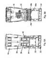
- FIG. 5Ashows a schematic side view of the attachment of FIG. 3 in the direction of the arrow B in FIG. 3 with retracted pin parts;
- FIG. 5Bshows a schematic section view of the attachment of FIG. 3 along the line C-C in FIG. 3 with retracted pin parts;
- FIG. 6Ashows a schematic side view of the attachment of FIG. 3 in the direction of the arrow B in FIG. 3 with extended pin parts;
- FIG. 6Bshows a schematic section view of the attachment of FIG. 3 along the line C-C in FIG. 3 with extended pin parts;
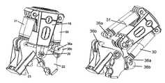
- FIG. 6Cshows a schematic perspective view of the attachment of FIG. 3 with extended pin parts
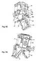
- FIG. 7A to Gshows various states of the attachment in perspective view in order to illustrate the process of removing the tool from the attachment.
- FIG. 1shows first of all, by way of example, a construction machine with an implement 10 , for example in the form of an excavator.
- An attachment 14is fixed to the implement 10 by means of an equipment carrier 12 (e.g. swivel arm, jib etc.).
- the attachment 14contains a frame 16 , a tool 18 attached to the frame 16 , and a tool drive 20 attached to the frame 16 for actuating the tool 18 .
- a hydraulic systemwhich is connected by means of hydraulic pipes fed along the equipment carrier 12 to the hydraulic tool drive 20 (for moving the tool) and to a hydraulic attachment drive (for rotating the attachment about its longitudinal axis), is provided on the implement 10 in the usual manner.
- the attachmentis attached to the equipment carrier 12 by means of the coupling unit, which also makes a connection to the appropriate hydraulic pipes.
- the attachment 14is designed so that the tool 18 can be removed from the frame 16 and the tool drive 20 of the attachment 14 . This enables the attachment to be quickly matched to the different tasks to be carried out directly on site in order to reduce the stoppage times without having to provide a large fleet of machines with a high number of different complete attachments.
- the frame 16 and therefore the complete attachment 14can of course also be removed from the equipment carrier 12 if required.
- the attachment shown in the figuresis equipped with a pair of concrete-breaking pliers as a tool.
- Other types of toolcan of course also be used with the attachment according to the invention.
- demolition and scrap shears, demolition and scrap pliers, combi-pliers, pulverizers and demolition and sorting grippersare mentioned in this regard.
- the frame 16serves as a carrier for the respective tool 18 and the corresponding tool drive 20 .
- the frame 16is designed with a coupling unit 21 in order to attach the frame 16 to the equipment carrier 12 in a detachable manner.
- This coupling unit 21serves both as the mechanical connection between the frame 16 and the equipment carrier 12 , and the connection of the tool drive 20 and other drives to the drive system of the implement 10 . This is usually a hydraulic system.
- the tool 18essentially comprises two tool parts 22 and 23 , which in the present case are designed as plier jaws of a pair of concrete-breaking pliers.
- the two plier jaws 22 , 23are in each case designed with a plurality of tooth-shaped concrete-breaking sections 24 and a plurality of cutters 25 so that the concrete-breaking pliers 18 can be used both for breaking concrete slabs and also for cutting steel beams.
- An example of a possible design of such a pair of concrete-breaking pliers 18is described in more detail in the already mentioned WO 96/02708 A1.
- the frame 16has a substantially centrally arranged joint 26 .
- This joint 26contains a multi-part pin 28 , which will be described later in more detail and to which the two plier jaws 22 , 23 are mounted so that they can be pivoted relative to one another. This means that either both plier jaws 22 , 23 can be pivoted about the joint 26 , or only one of the two plier jaws 22 , 23 can be pivoted about the joint 26 while the other is attached rigidly to the frame 16 .
- the tool drive 20 for this tool 18has a plurality of lifting cylinders 30 , 31 .
- Two first lifting cylinders 30are in each case connected via a first link point 34 to the frame 16 and detachably coupled via a second link point 36 to the first tool part 22 .
- two second lifting cylinders 31are in each case connected via a first link point 34 to the frame 16 and detachably coupled via a second link point 36 to the first tool part 23 .
- the second tool part 23is to be rigidly fixed to the frame 16 , then rigid retaining devices are used instead of the second lifting cylinder 31 .
- These rigid retaining devicesare however likewise provided with a second link device 36 which enables the second tool part 23 to be removed.
- only one lifting cylinder 30 , 31 in each case or more than two lifting cylinders 30 , 31can of course also be used.
- the inventionis also not restricted to hydraulic lifting cylinders; basically other tool drives 20 can also be used.
- the two link devices 36are additionally connected to the central joint 26 by means of levers 38 , 40 .
- the levers 38 , 40are designed, for example, in the form of toggle levers as shown in FIG. 4 .
- the appropriate lever 40serves as a stable support for the second link device 36 .
- FIGS. 6 and 7The design and principle of operation of the joint 26 of the attachment 14 and of the second link device 36 are shown in more detail in FIGS. 6 and 7 in different views and different operating states of the attachment 14 .
- the joint 26 of the attachment 14 attached to the frame 16is formed in particular by a multi-part pin 28 which is attached to the frame 16 and fixed to rotate therewith.
- the pin 28is made up of three pin parts, namely a middle pin part 28 a and two outer pin parts 28 b which are arranged behind one another in the longitudinal direction of the pin (e.g. left/right direction in FIG. 5B ) and connected to one another.
- the middle pin part 28 ahas a recess on each of its two face sides, for example, in which the face sides of the outer pin parts 28 b are inserted, as can best be seen in FIG. 5B .
- the altogether three pin parts 28 a , 28 bare preferably designed and arranged symmetrically.
- the middle pin part 28 ais fixed to the frame 16 of the attachment 14 .
- the movement of the outer pin parts 28 btakes place via two drive elements of a pin drive 42 .
- the two drive elements of the pin drive 42are in the form of hydraulic cylinders, the piston rods of which are securely connected to the outer pin parts 28 b of the joint pin 28 , as is shown in FIGS. 5B and 6B .
- pin drive 42can also be used for the pin drive 42 .
- other drive elementssuch as electric motor drives for example, can also be used for the pin drive 42 .
- only one common pin drive 42can also be provided for moving the two outer pin parts 28 b .
- the pin drive 42is modified accordingly for differently divided pins 28 .
- Each of the two outer pin parts 28 bis retained and guided in the frame 16 by an appropriately dimensioned and designed through-opening of a side cheek 44 .
- the side cheeks 44are preferably formed in one piece with the frame 16 .
- the levers 38 , 40are mounted on the middle pin part 28 a so that a defined movement of the two link devices 36 also takes place for the lifting cylinders 30 , 31 when the tool parts 22 , 23 are detachable.
- the two tool parts 22 , 23each have side cheeks 46 which are provided with through-openings, through which the outer pin parts 28 b of the link pin 28 can be fed.
- the side cheeks 46 of the tool parts 22 , 23are pivotably mounted on the outer pin parts 28 b .
- the outer pin parts 28 bare separated from the middle pin part 28 a in opposite directions by the pin drive 42 (see FIG. 6A to C)
- the side cheeks 46 of the tool parts 22 , 23can be removed from the joint 26 of the attachment 14 perpendicular to the longitudinal axis of the pin 28 (i.e. for example downwards in FIG. 6A ).
- the outer pin parts 28 bare pre-stressed by the pin drive 42 , preferably in their positions in which they are connected to the middle pin part 28 a .
- the outer pin parts 28 bcan also be locked in these positions to retain the tool parts 22 , 23 .
- the second link devices 36are made up of a first engagement element 36 a , which is fixed to a lifting cylinder 30 , 31 of the tool drive 20 , and a second engagement element 36 b , which is fixed to a tool part 22 , 23 or formed in one piece therewith.
- the first and second engagement elements 36 a , 36 bare in each case detachably engaged with one another.
- the tool parts 22 , 23each have side cheeks 48 which are designed with a hook-shaped second engagement element 36 b .
- the side cheeks 48are preferably designed in one piece with the side cheeks 46 , which have the through-openings for the outer pin parts 28 b .
- the lifting cylinders 30 , 31At their ends facing the tool parts 22 , 23 , the lifting cylinders 30 , 31 each have a substantially bar-shaped first engagement element 36 a .
- the bar-shaped first engagement elements 36 acan be moved in the direction perpendicular to their longitudinal axis out of the hook-shaped second engagement elements 36 b in the side cheeks 48 of the tool parts.
- connection of these two link devices 36is easily removed by actuating the tool drive 20 , i.e. the lifting cylinders 30 , 31 . This sequence of movements is explained below with reference to FIG. 7A to G.
- the second link devices 36are not restricted to this embodiment only.
- the first engagement elements 36 a on the lifting cylinders 30 , 31can likewise be designed as pin-shaped engagement elements which can be slid in the direction of their longitudinal axis.
- the second engagement elements 36 bare designed as cylindrical engagement elements, for example in the form of through-openings in the side cheeks 48 of the tool parts 22 , 23 .
- the removal of the connection of such a second link device 36can take place, for example, in parallel with the removal of the link connection in that the pin drive 42 simultaneously moves the pin-shaped first engagement elements 36 a of the second link devices 36 .
- the second link devices 36can of course also be constructed with a reverse design of the first and second engagement elements. That is to say, for example, that the first engagement elements 36 a on the lifting cylinders 30 , 31 can also be designed in the shape of a hook, and the second engagement elements 36 b on the side cheeks 48 of the tool parts 22 , 23 can be designed in the shape of a bar.
- the pin drive 42is formed by hydraulic drive elements.
- the pin drive 42in order to avoid a retrospective modification or conversion of the hydraulic system of implement 10 and/or equipment carrier 12 , the pin drive 42 is likewise connected to the hydraulic supply lines of the attachment drive.
- a switch elemente.g. manual or remote-controlled, not shown
- the attachment 14As a rotary drive of the attachment 14 is not necessary during a tool change, this enables additional supply lines for the pin drive 42 to be dispensed with. A changeover of this kind is not necessary in the case of electric-motor-driven drive elements for the pin drive 42 .
- the fitting of the tool 18 to the frame 16 and to the tool drive 20can be carried out in the correspondingly reverse order.
- FIG. 7Afirst of all shows the initial state of the attachment 14 in which the tool parts 22 , 23 are fixed to the frame 16 and to the tool drive 20 so that the attachment 14 is ready for use.
- the outer pin parts 28 bare now removed from the joint 26 by means of the pin drive 42 (cf. FIG. 7B ) after the drive supply lines have been changed over accordingly if necessary.
- the side cheeks 46 of the tool parts 22 , 23can be removed from the joint 26 .
- FIG. 7Cthis takes place in that the piston rods of the lifting cylinders 30 , 31 are extended and therefore the frame 16 is pulled away from the tool 18 .
- the frame 16 of the attachment 14can be lifted slightly by means of the equipment carrier 12 .
- the first and second engagement elements 36 a , 36 b of the second link devices 36 on the other side for the other tool part 22can be separated from one another as shown in FIG. 7F .
- the second link devices 36are connected via rigidly designed levers 38 , 40 to the central joint 26 on the frame 16 , and the first and the second engagement elements 36 a , 36 b of the second link devices 36 are separated from one another when the tool 18 is removed by means of the lifting cylinders 30 , 31 of the tool drive 20 .
- the levers 38 , 44 guiding the movement of the second link devices 36 relative to the joint 26can also be designed as adjustable-length levers.
- the drive for changing the length of these adjustable-length leverscan also, for example, have hydraulic and/or electric-motor-driven drive elements.
- hydraulic drive elementsthese can be changed over to the hydraulic supply lines of the attachment drive in parallel with the supply of the pin drive 42 .
- these adjustable-length leversWhen the attachment 14 is operated with coupled tool 18 , these adjustable-length levers must have a predetermined fixed length so that a movement of the lifting cylinders 30 , 31 leads to a pivoting of the tool parts 22 , 23 about the joint 26 .
- the first and second engagement elements 36 a , 36 b of the second link devices 36can then be removed from one another by changing the length of the adjustable-length levers.
Landscapes
- Engineering & Computer Science (AREA)
- Architecture (AREA)
- Structural Engineering (AREA)
- Mechanical Engineering (AREA)
- Civil Engineering (AREA)
- General Engineering & Computer Science (AREA)
- Mining & Mineral Resources (AREA)
- Electrochemistry (AREA)
- Chemical Kinetics & Catalysis (AREA)
- Chemical & Material Sciences (AREA)
- Working Measures On Existing Buildindgs (AREA)
- Earth Drilling (AREA)
- Manipulator (AREA)
- Shovels (AREA)
- Pivots And Pivotal Connections (AREA)
Abstract
Description
Claims (14)
Applications Claiming Priority (4)
| Application Number | Priority Date | Filing Date | Title |
|---|---|---|---|
| DE102009012050 | 2009-03-06 | ||
| DE102009012050ADE102009012050A1 (en) | 2009-03-06 | 2009-03-06 | attachment |
| DE102009012050.5 | 2009-03-06 | ||
| PCT/EP2010/001390WO2010099980A1 (en) | 2009-03-06 | 2010-03-05 | Attachment for construction equipment |
Publications (2)
| Publication Number | Publication Date |
|---|---|
| US20120126559A1 US20120126559A1 (en) | 2012-05-24 |
| US8887416B2true US8887416B2 (en) | 2014-11-18 |
Family
ID=42207301
Family Applications (1)
| Application Number | Title | Priority Date | Filing Date |
|---|---|---|---|
| US13/254,879Active2031-06-01US8887416B2 (en) | 2009-03-06 | 2010-03-05 | Attachment for construction equipment |
Country Status (6)
| Country | Link |
|---|---|
| US (1) | US8887416B2 (en) |
| EP (1) | EP2403998B1 (en) |
| CA (1) | CA2763346C (en) |
| DE (1) | DE102009012050A1 (en) |
| EA (1) | EA201171106A1 (en) |
| WO (1) | WO2010099980A1 (en) |
Cited By (3)
| Publication number | Priority date | Publication date | Assignee | Title |
|---|---|---|---|---|
| US20130011180A1 (en)* | 2010-03-30 | 2013-01-10 | C.M.C. S.R.L. - Societa Unipersonale | Quick safety connection for coupling a tool to an operating machine |
| US10967380B2 (en) | 2017-03-31 | 2021-04-06 | Stanley Black & Decker, Inc. | Heavy duty material processor |
| USD943012S1 (en)* | 2020-09-04 | 2022-02-08 | Demolition and Recylcing Equipment B.V. | Cutting shears |
Families Citing this family (3)
| Publication number | Priority date | Publication date | Assignee | Title |
|---|---|---|---|---|
| US6994284B1 (en) | 1999-10-15 | 2006-02-07 | Ramun John R | Multiple tool attachment system |
| US8308092B2 (en) | 1999-10-15 | 2012-11-13 | Ramun John R | Multiple tool attachment system with universal body with grapple |
| CN114396088A (en)* | 2021-12-21 | 2022-04-26 | 三一汽车制造有限公司 | Accessory positioning device, working machine and method for using accessory positioning device |
Citations (41)
| Publication number | Priority date | Publication date | Assignee | Title |
|---|---|---|---|---|
| AT77670B (en) | 1917-11-22 | 1919-08-11 | Peter Kazda | Drive belt. |
| US4726731A (en)* | 1984-12-07 | 1988-02-23 | Jones Paul O | Hitch |
| US4838493A (en)* | 1988-06-10 | 1989-06-13 | Labounty Kenneth R | Concrete crusher |
| US4934462A (en) | 1988-11-21 | 1990-06-19 | J. I. Case Company | Control device for a dual function machine |
| DE4102370A1 (en) | 1990-02-12 | 1991-08-14 | Walter Fritzel | Excavator with bucket secured by quick action coupling - which is actuated by compressed air stored in hollow outer arm |
| US5044569A (en) | 1989-12-15 | 1991-09-03 | Labounty Roy E | Rock and coral demolition tool |
| DE4109783A1 (en) | 1990-03-23 | 1991-09-26 | Hilton S Enterprises Inc Pty L | Bucket for earth moving machine - is held in place by hydraulic cylinders which hold attachment hooks in engagement |
| US5060378A (en) | 1989-12-15 | 1991-10-29 | Labounty Manufacturing, Inc. | Demolition tool for a hydraulic excavator |
| US5062227A (en)* | 1989-06-20 | 1991-11-05 | Verachtert Beheer B.V. | Device for breaking objects consisting of concrete or similar material |
| US5145313A (en)* | 1991-06-28 | 1992-09-08 | Weyer Paul P | Quick disconnect bucket actuator |
| US5242258A (en)* | 1991-06-28 | 1993-09-07 | Weyer Paul P | Quick disconnect bucket actuator |
| DE9209675U1 (en) | 1992-07-18 | 1993-11-18 | O & K Orenstein & Koppel Ag, 13581 Berlin | Quick change device |
| DE9408196U1 (en) | 1994-05-18 | 1994-08-11 | Ostermeyer, Thomas, Dipl.-Ing., 88400 Biberach | Quick change device |
| EP0641618A1 (en) | 1993-09-02 | 1995-03-08 | Methold 's-Hertogenbosch B.V. | A device for crushing and/or cutting material |
| DE4417401A1 (en) | 1994-05-18 | 1995-11-30 | Thomas Dipl Ing Ostermeyer | Equipment carrier |
| WO1996002708A1 (en) | 1994-07-13 | 1996-02-01 | Schilling-Ostermeyer Maschinenbau Gmbh | Concrete breaking pliers |
| US5533682A (en)* | 1993-09-02 | 1996-07-09 | Methold 's-Hertogenbosch B.V. | Device for crushing and/or cutting material |
| US5546683A (en)* | 1993-09-29 | 1996-08-20 | Clark; George J. | Bucket attachment device with remote controlled retractable pins |
| US5562397A (en)* | 1994-07-13 | 1996-10-08 | Clark Equipment Company | Power actuator for attachment plate |
| DE29708705U1 (en) | 1997-05-16 | 1997-07-10 | Caterpillar Vibra-Ram GmbH & Co.KG, 66482 Zweibrücken | Demolition device for heavy loads, especially demolition or scrap shears |
| WO1997030232A1 (en) | 1996-02-15 | 1997-08-21 | Alois Wimmer | Concrete breaking jaw assembly with cutting claws |
| US5692325A (en)* | 1996-02-06 | 1997-12-02 | Konan Electric Company Limited | Attachment detaching apparatus for hydraulic shovel |
| US5802753A (en)* | 1994-02-09 | 1998-09-08 | Raunisto; Yrjoe | Quick coupling assembly |
| DE19832699A1 (en) | 1998-07-21 | 1999-06-10 | Ludwig Schnell | Hydraulic breaker mouth for fluidized lift marine dredger |
| US6241455B1 (en)* | 1999-08-31 | 2001-06-05 | Case Corporation | Earth-moving machine bucket coupler |
| WO2001068992A1 (en) | 2000-03-14 | 2001-09-20 | Genesis Equipment & Manufacturing, Inc. | Shear with replaceable tip and rotatable cross blade |
| JP2001288769A (en) | 2000-04-04 | 2001-10-19 | Shin Caterpillar Mitsubishi Ltd | Quick coupler device for work machinery |
| US6332747B1 (en)* | 1999-05-11 | 2001-12-25 | Daemo Engineering Co., Ltd. | Coupling apparatus for detachably attaching an excavating device to excavator |
| FR2822482A1 (en) | 2001-03-22 | 2002-09-27 | Jean Pierre Dorguin | Accessory fitting and release system for contruction or demolition machine jib has extending/retracting axles operated by cranked hand tool |
| DE10200836A1 (en) | 2002-01-08 | 2003-07-24 | Thomas Sauer | Rapid tool changing mechanism for excavator, bulldozer or mechanical loader includes quick release couplings for hydraulic lines at sides of mounting frame |
| US6655054B1 (en)* | 1999-08-19 | 2003-12-02 | Peter John Ward | Quick hitch attachment |
| EP1605104A1 (en) | 2004-06-08 | 2005-12-14 | Atlas Copco Construction Tools GmbH | Demolition tool mountable on a working arm |
| US6994284B1 (en)* | 1999-10-15 | 2006-02-07 | Ramun John R | Multiple tool attachment system |
| US7000339B1 (en)* | 1999-08-31 | 2006-02-21 | Ramun John R | Demolition equipment having universal tines and a method for designing a universal tine |
| US7014385B2 (en)* | 2001-09-26 | 2006-03-21 | Hanwoo Tnc Corporation | Attachment coupling device for heavy machinery |
| US20060237204A1 (en) | 2005-04-16 | 2006-10-26 | Rastegar Jahangir S | Manually operated impact wrench |
| US20070001041A1 (en)* | 2005-06-29 | 2007-01-04 | Christenson Ross D | Excavator demolition attachment with interchangeable jaw assemblies |
| US7237738B2 (en)* | 2002-08-06 | 2007-07-03 | Nippon Pneumatic Manufacturing Co., Ltd. | Demolishing and cutting machine |
| DE60311700T2 (en) | 2002-05-23 | 2007-11-22 | Komatsu Ltd. | Hydraulic circuit for additional work equipment |
| US7954742B2 (en)* | 1999-10-15 | 2011-06-07 | Ramun John R | Dual purpose adapter for a multiple tool attachment system |
| US7984575B2 (en)* | 2007-07-05 | 2011-07-26 | Caterpillar Inc. | Quick coupler assembly |
- 2009
- 2009-03-06DEDE102009012050Apatent/DE102009012050A1/ennot_activeCeased
- 2010
- 2010-03-05EPEP10716277.8Apatent/EP2403998B1/enactiveActive
- 2010-03-05WOPCT/EP2010/001390patent/WO2010099980A1/enactiveApplication Filing
- 2010-03-05CACA2763346Apatent/CA2763346C/enactiveActive
- 2010-03-05USUS13/254,879patent/US8887416B2/enactiveActive
- 2010-03-05EAEA201171106Apatent/EA201171106A1/enunknown
Patent Citations (51)
| Publication number | Priority date | Publication date | Assignee | Title |
|---|---|---|---|---|
| AT77670B (en) | 1917-11-22 | 1919-08-11 | Peter Kazda | Drive belt. |
| US4726731A (en)* | 1984-12-07 | 1988-02-23 | Jones Paul O | Hitch |
| US4838493B1 (en)* | 1988-06-10 | 1994-12-06 | Labounty Manufacturing | Concrete crusher |
| US4838493A (en)* | 1988-06-10 | 1989-06-13 | Labounty Kenneth R | Concrete crusher |
| US4934462A (en) | 1988-11-21 | 1990-06-19 | J. I. Case Company | Control device for a dual function machine |
| ATE77670T1 (en) | 1988-11-21 | 1992-07-15 | Case Poclain | CONTROL DEVICE FOR AN EARTH-MOVING MACHINE. |
| US5062227A (en)* | 1989-06-20 | 1991-11-05 | Verachtert Beheer B.V. | Device for breaking objects consisting of concrete or similar material |
| US5044569A (en) | 1989-12-15 | 1991-09-03 | Labounty Roy E | Rock and coral demolition tool |
| US5060378A (en) | 1989-12-15 | 1991-10-29 | Labounty Manufacturing, Inc. | Demolition tool for a hydraulic excavator |
| DE4102370A1 (en) | 1990-02-12 | 1991-08-14 | Walter Fritzel | Excavator with bucket secured by quick action coupling - which is actuated by compressed air stored in hollow outer arm |
| DE4109783A1 (en) | 1990-03-23 | 1991-09-26 | Hilton S Enterprises Inc Pty L | Bucket for earth moving machine - is held in place by hydraulic cylinders which hold attachment hooks in engagement |
| US5145313A (en)* | 1991-06-28 | 1992-09-08 | Weyer Paul P | Quick disconnect bucket actuator |
| US5242258A (en)* | 1991-06-28 | 1993-09-07 | Weyer Paul P | Quick disconnect bucket actuator |
| DE9209675U1 (en) | 1992-07-18 | 1993-11-18 | O & K Orenstein & Koppel Ag, 13581 Berlin | Quick change device |
| EP0641618A1 (en) | 1993-09-02 | 1995-03-08 | Methold 's-Hertogenbosch B.V. | A device for crushing and/or cutting material |
| US5533682A (en)* | 1993-09-02 | 1996-07-09 | Methold 's-Hertogenbosch B.V. | Device for crushing and/or cutting material |
| US5546683A (en)* | 1993-09-29 | 1996-08-20 | Clark; George J. | Bucket attachment device with remote controlled retractable pins |
| DE69526722T2 (en) | 1994-02-09 | 2003-01-02 | Raunisto, Airi | QUICK RELEASE |
| US5802753A (en)* | 1994-02-09 | 1998-09-08 | Raunisto; Yrjoe | Quick coupling assembly |
| DE9408196U1 (en) | 1994-05-18 | 1994-08-11 | Ostermeyer, Thomas, Dipl.-Ing., 88400 Biberach | Quick change device |
| DE4417401A1 (en) | 1994-05-18 | 1995-11-30 | Thomas Dipl Ing Ostermeyer | Equipment carrier |
| US5822893A (en)* | 1994-07-13 | 1998-10-20 | Schilling-Ostermeyer Maschinenbau Gmbh | Concrete crushing tongs |
| US5562397A (en)* | 1994-07-13 | 1996-10-08 | Clark Equipment Company | Power actuator for attachment plate |
| WO1996002708A1 (en) | 1994-07-13 | 1996-02-01 | Schilling-Ostermeyer Maschinenbau Gmbh | Concrete breaking pliers |
| US5692325A (en)* | 1996-02-06 | 1997-12-02 | Konan Electric Company Limited | Attachment detaching apparatus for hydraulic shovel |
| WO1997030232A1 (en) | 1996-02-15 | 1997-08-21 | Alois Wimmer | Concrete breaking jaw assembly with cutting claws |
| DE29708705U1 (en) | 1997-05-16 | 1997-07-10 | Caterpillar Vibra-Ram GmbH & Co.KG, 66482 Zweibrücken | Demolition device for heavy loads, especially demolition or scrap shears |
| DE19832699A1 (en) | 1998-07-21 | 1999-06-10 | Ludwig Schnell | Hydraulic breaker mouth for fluidized lift marine dredger |
| US6332747B1 (en)* | 1999-05-11 | 2001-12-25 | Daemo Engineering Co., Ltd. | Coupling apparatus for detachably attaching an excavating device to excavator |
| US6655054B1 (en)* | 1999-08-19 | 2003-12-02 | Peter John Ward | Quick hitch attachment |
| US6241455B1 (en)* | 1999-08-31 | 2001-06-05 | Case Corporation | Earth-moving machine bucket coupler |
| US7000339B1 (en)* | 1999-08-31 | 2006-02-21 | Ramun John R | Demolition equipment having universal tines and a method for designing a universal tine |
| US7108211B2 (en)* | 1999-10-15 | 2006-09-19 | Ramun John R | Multiple tool attachment system |
| US8424789B2 (en)* | 1999-10-15 | 2013-04-23 | John R. Ramun | Demolition tool unit and method of designing and forming a demolition tool unit |
| US8245964B2 (en)* | 1999-10-15 | 2012-08-21 | Ramun John R | Dual moving jaws for demolition equipment |
| US7954742B2 (en)* | 1999-10-15 | 2011-06-07 | Ramun John R | Dual purpose adapter for a multiple tool attachment system |
| US6994284B1 (en)* | 1999-10-15 | 2006-02-07 | Ramun John R | Multiple tool attachment system |
| US7121489B2 (en)* | 1999-10-15 | 2006-10-17 | Ramun John R | Multiple tool attachment system |
| WO2001068992A1 (en) | 2000-03-14 | 2001-09-20 | Genesis Equipment & Manufacturing, Inc. | Shear with replaceable tip and rotatable cross blade |
| JP2001288769A (en) | 2000-04-04 | 2001-10-19 | Shin Caterpillar Mitsubishi Ltd | Quick coupler device for work machinery |
| FR2822482A1 (en) | 2001-03-22 | 2002-09-27 | Jean Pierre Dorguin | Accessory fitting and release system for contruction or demolition machine jib has extending/retracting axles operated by cranked hand tool |
| US7014385B2 (en)* | 2001-09-26 | 2006-03-21 | Hanwoo Tnc Corporation | Attachment coupling device for heavy machinery |
| DE10200836A1 (en) | 2002-01-08 | 2003-07-24 | Thomas Sauer | Rapid tool changing mechanism for excavator, bulldozer or mechanical loader includes quick release couplings for hydraulic lines at sides of mounting frame |
| DE60311700T2 (en) | 2002-05-23 | 2007-11-22 | Komatsu Ltd. | Hydraulic circuit for additional work equipment |
| US7237738B2 (en)* | 2002-08-06 | 2007-07-03 | Nippon Pneumatic Manufacturing Co., Ltd. | Demolishing and cutting machine |
| US7412788B2 (en)* | 2004-06-08 | 2008-08-19 | Atlas Copco Construction Tools Gmbh | Demolition claw |
| EP1605104A1 (en) | 2004-06-08 | 2005-12-14 | Atlas Copco Construction Tools GmbH | Demolition tool mountable on a working arm |
| US20060237204A1 (en) | 2005-04-16 | 2006-10-26 | Rastegar Jahangir S | Manually operated impact wrench |
| US20070001041A1 (en)* | 2005-06-29 | 2007-01-04 | Christenson Ross D | Excavator demolition attachment with interchangeable jaw assemblies |
| US7284718B2 (en)* | 2005-06-29 | 2007-10-23 | Genesis Attachments, Llc | Excavator demolition attachment with interchangeable jaw assemblies |
| US7984575B2 (en)* | 2007-07-05 | 2011-07-26 | Caterpillar Inc. | Quick coupler assembly |
Non-Patent Citations (1)
| Title |
|---|
| International Search Report for PCT/EP2010/001390 mailed Jun. 18, 2010. |
Cited By (4)
| Publication number | Priority date | Publication date | Assignee | Title |
|---|---|---|---|---|
| US20130011180A1 (en)* | 2010-03-30 | 2013-01-10 | C.M.C. S.R.L. - Societa Unipersonale | Quick safety connection for coupling a tool to an operating machine |
| US9167739B2 (en)* | 2010-03-30 | 2015-10-27 | C.M.C. S.R.L.-Societa Unipersonale | Quick safety connection for coupling a tool to an operating machine |
| US10967380B2 (en) | 2017-03-31 | 2021-04-06 | Stanley Black & Decker, Inc. | Heavy duty material processor |
| USD943012S1 (en)* | 2020-09-04 | 2022-02-08 | Demolition and Recylcing Equipment B.V. | Cutting shears |
Also Published As
| Publication number | Publication date |
|---|---|
| DE102009012050A1 (en) | 2010-09-09 |
| CA2763346C (en) | 2017-01-10 |
| US20120126559A1 (en) | 2012-05-24 |
| WO2010099980A1 (en) | 2010-09-10 |
| EA201171106A1 (en) | 2012-03-30 |
| EP2403998A1 (en) | 2012-01-11 |
| EP2403998B1 (en) | 2013-07-03 |
| CA2763346A1 (en) | 2010-09-10 |
Similar Documents
| Publication | Publication Date | Title |
|---|---|---|
| US8887416B2 (en) | Attachment for construction equipment | |
| US8910693B2 (en) | Device for demounting a tire from a rim as well as a tire demounting machine equipped with such device | |
| US20130330161A1 (en) | Locking mechanism for lift arm assembly | |
| JP2012121567A5 (en) | ||
| CA2886737C (en) | Thumb assembly | |
| SE535904C2 (en) | Switching device at a remote controlled workable arm equipped machine | |
| CA2494933C (en) | Cutting or crushing implement | |
| US11559814B2 (en) | Double acting demolition device and utility machine for demolishing structures | |
| JP3174918U (en) | Cutting and clamping combined dismantling machine | |
| JP5801738B2 (en) | Structure demolition machine | |
| KR101254193B1 (en) | Attachment quick change construction for heavy equipment | |
| KR101442165B1 (en) | An excavator's gripper of a clamp installation type | |
| US11638921B2 (en) | Demolition device and utility machine for demolishing a concrete structure | |
| JPH02104824A (en) | Working machine attaching or removing apparatus for hydraulic type shovel | |
| EP1672126B1 (en) | Pinned boom for earth moving machines equipped with a hydraulic apparatus for the insertion and for the extraction of junction pins. | |
| JP2005002688A (en) | Disassembling attachment and disassembling machine | |
| JP4409232B2 (en) | Work machine coupling device | |
| KR20170009152A (en) | Multi-function ripper for excavator car car that can be simultaneously exert tongs function and ripper of function | |
| JP6552379B2 (en) | Tractor and front loader | |
| US20250034833A1 (en) | Quick coupling system | |
| JP2008138382A (en) | Dismantling machine for cutting and pinching | |
| KR20120001125U (en) | Cutting device for knuckle crane | |
| JP2006077445A (en) | Grip fork attachment making use of bucket | |
| JP2012101907A (en) | Attachment for holding floor steel plate | |
| CN104617520A (en) | Wire clamping device and method for clamping wire-shaped body by using wire clamping device |
Legal Events
| Date | Code | Title | Description |
|---|---|---|---|
| AS | Assignment | Owner name:LST GMBH, GERMANY Free format text:ASSIGNMENT OF ASSIGNORS INTEREST;ASSIGNOR:OSTERMEYER, THOMAS;REEL/FRAME:027241/0718 Effective date:20111111 | |
| AS | Assignment | Owner name:IMBOLEX ENGINEERING GMBH, GERMANY Free format text:ASSIGNMENT OF ASSIGNORS INTEREST;ASSIGNOR:LST GMBH;REEL/FRAME:032101/0286 Effective date:20130925 | |
| STCF | Information on status: patent grant | Free format text:PATENTED CASE | |
| AS | Assignment | Owner name:GEBRUDER EGLI MASCHINEN AG, SWITZERLAND Free format text:ASSIGNMENT OF ASSIGNORS INTEREST;ASSIGNOR:IMBOLEX ENGINEERING GMBH;REEL/FRAME:034912/0413 Effective date:20150115 | |
| MAFP | Maintenance fee payment | Free format text:PAYMENT OF MAINTENANCE FEE, 4TH YEAR, LARGE ENTITY (ORIGINAL EVENT CODE: M1551) Year of fee payment:4 | |
| FEPP | Fee payment procedure | Free format text:ENTITY STATUS SET TO SMALL (ORIGINAL EVENT CODE: SMAL) | |
| MAFP | Maintenance fee payment | Free format text:PAYMENT OF MAINTENANCE FEE, 4TH YR, SMALL ENTITY (ORIGINAL EVENT CODE: M2551) Year of fee payment:4 | |
| REFU | Refund | Free format text:REFUND - PAYMENT OF MAINTENANCE FEE, 4TH YEAR, LARGE ENTITY (ORIGINAL EVENT CODE: R1551) | |
| MAFP | Maintenance fee payment | Free format text:PAYMENT OF MAINTENANCE FEE, 8TH YR, SMALL ENTITY (ORIGINAL EVENT CODE: M2552); ENTITY STATUS OF PATENT OWNER: SMALL ENTITY Year of fee payment:8 |