US8883297B2 - Methods for bonding porous flexible membranes using solvent - Google Patents
Methods for bonding porous flexible membranes using solventDownload PDFInfo
- Publication number
- US8883297B2 US8883297B2US12/577,131US57713109AUS8883297B2US 8883297 B2US8883297 B2US 8883297B2US 57713109 AUS57713109 AUS 57713109AUS 8883297 B2US8883297 B2US 8883297B2
- Authority
- US
- United States
- Prior art keywords
- flexible membrane
- porous flexible
- membrane
- bonding
- solvent
- Prior art date
- Legal status (The legal status is an assumption and is not a legal conclusion. Google has not performed a legal analysis and makes no representation as to the accuracy of the status listed.)
- Expired - Fee Related, expires
Links
- 239000012528membraneSubstances0.000titleclaimsabstractdescription238
- 239000002904solventSubstances0.000titleclaimsabstractdescription118
- 238000000034methodMethods0.000titleclaimsabstractdescription59
- 239000000463materialSubstances0.000claimsabstractdescription115
- 238000002203pretreatmentMethods0.000claimsabstractdescription54
- 239000011148porous materialSubstances0.000claimsabstractdescription32
- 238000001035dryingMethods0.000claimsabstractdescription10
- 238000003825pressingMethods0.000claimsabstractdescription3
- 239000004800polyvinyl chlorideSubstances0.000claimsdescription33
- 229920000915polyvinyl chloridePolymers0.000claimsdescription32
- ZMXDDKWLCZADIW-UHFFFAOYSA-NN,N-DimethylformamideChemical compoundCN(C)C=OZMXDDKWLCZADIW-UHFFFAOYSA-N0.000claimsdescription31
- ZWEHNKRNPOVVGH-UHFFFAOYSA-N2-ButanoneChemical compoundCCC(C)=OZWEHNKRNPOVVGH-UHFFFAOYSA-N0.000claimsdescription30
- CSCPPACGZOOCGX-UHFFFAOYSA-NAcetoneChemical compoundCC(C)=OCSCPPACGZOOCGX-UHFFFAOYSA-N0.000claimsdescription22
- WYURNTSHIVDZCO-UHFFFAOYSA-NTetrahydrofuranChemical compoundC1CCOC1WYURNTSHIVDZCO-UHFFFAOYSA-N0.000claimsdescription20
- YLQBMQCUIZJEEH-UHFFFAOYSA-NtetrahydrofuranNatural productsC=1C=COC=1YLQBMQCUIZJEEH-UHFFFAOYSA-N0.000claimsdescription10
- VYPSYNLAJGMNEJ-UHFFFAOYSA-NSilicium dioxideChemical compoundO=[Si]=OVYPSYNLAJGMNEJ-UHFFFAOYSA-N0.000claimsdescription6
- 229920003229poly(methyl methacrylate)Polymers0.000claimsdescription6
- 239000004926polymethyl methacrylateSubstances0.000claimsdescription6
- 230000002209hydrophobic effectEffects0.000claimsdescription5
- 150000002500ionsChemical class0.000claimsdescription4
- 239000002245particleSubstances0.000claimsdescription4
- 229920000098polyolefinPolymers0.000claimsdescription4
- 239000000377silicon dioxideSubstances0.000claimsdescription3
- 238000009736wettingMethods0.000claimsdescription3
- 235000012239silicon dioxideNutrition0.000claimsdescription2
- 239000002344surface layerSubstances0.000claims1
- 239000000243solutionSubstances0.000description35
- 239000003792electrolyteSubstances0.000description19
- 239000003014ion exchange membraneSubstances0.000description16
- 239000007864aqueous solutionSubstances0.000description12
- 239000008151electrolyte solutionSubstances0.000description5
- 239000010410layerSubstances0.000description5
- 238000006479redox reactionMethods0.000description5
- 230000002411adverseEffects0.000description4
- 239000012736aqueous mediumSubstances0.000description3
- 238000004140cleaningMethods0.000description3
- 238000007254oxidation reactionMethods0.000description3
- GSNUFIFRDBKVIE-UHFFFAOYSA-NDMFNatural productsCC1=CC=C(C)O1GSNUFIFRDBKVIE-UHFFFAOYSA-N0.000description2
- 239000003929acidic solutionSubstances0.000description2
- 238000010349cathodic reactionMethods0.000description2
- 238000006243chemical reactionMethods0.000description2
- 238000009826distributionMethods0.000description2
- 238000001125extrusionMethods0.000description2
- 238000004519manufacturing processMethods0.000description2
- 239000003921oilSubstances0.000description2
- 229920003023plasticPolymers0.000description2
- 239000004033plasticSubstances0.000description2
- 238000005086pumpingMethods0.000description2
- 239000000376reactantSubstances0.000description2
- 238000010008shearingMethods0.000description2
- 229910021556Chromium(III) chlorideInorganic materials0.000description1
- 229910021577Iron(II) chlorideInorganic materials0.000description1
- 241000047703NonionSpecies0.000description1
- 239000004698PolyethyleneSubstances0.000description1
- 238000010521absorption reactionMethods0.000description1
- 230000002378acidificating effectEffects0.000description1
- 230000015572biosynthetic processEffects0.000description1
- QSWDMMVNRMROPK-UHFFFAOYSA-Kchromium(3+) trichlorideChemical compound[Cl-].[Cl-].[Cl-].[Cr+3]QSWDMMVNRMROPK-UHFFFAOYSA-K0.000description1
- 239000011636chromium(III) chlorideSubstances0.000description1
- 235000007831chromium(III) chlorideNutrition0.000description1
- 239000000470constituentSubstances0.000description1
- 239000000109continuous materialSubstances0.000description1
- 238000005336crackingMethods0.000description1
- 230000032798delaminationEffects0.000description1
- 230000001419dependent effectEffects0.000description1
- 238000000151depositionMethods0.000description1
- 238000007599dischargingMethods0.000description1
- 238000005516engineering processMethods0.000description1
- 239000000835fiberSubstances0.000description1
- 239000000945fillerSubstances0.000description1
- 238000011049fillingMethods0.000description1
- 238000001914filtrationMethods0.000description1
- 239000012530fluidSubstances0.000description1
- 238000005755formation reactionMethods0.000description1
- 239000000446fuelSubstances0.000description1
- 230000003834intracellular effectEffects0.000description1
- 238000005342ion exchangeMethods0.000description1
- NMCUIPGRVMDVDB-UHFFFAOYSA-Liron dichlorideChemical compoundCl[Fe]ClNMCUIPGRVMDVDB-UHFFFAOYSA-L0.000description1
- 239000002609mediumSubstances0.000description1
- 238000012986modificationMethods0.000description1
- 230000004048modificationEffects0.000description1
- 230000003647oxidationEffects0.000description1
- 239000013618particulate matterSubstances0.000description1
- 230000035515penetrationEffects0.000description1
- -1polyethylenePolymers0.000description1
- 229920000573polyethylenePolymers0.000description1
- 238000000746purificationMethods0.000description1
- 230000005855radiationEffects0.000description1
- 239000011347resinSubstances0.000description1
- 229920005989resinPolymers0.000description1
- 238000001223reverse osmosisMethods0.000description1
- 150000003839saltsChemical class0.000description1
- 238000000926separation methodMethods0.000description1
- 239000002356single layerSubstances0.000description1
- 239000007779soft materialSubstances0.000description1
- XLYOFNOQVPJJNP-UHFFFAOYSA-NwaterSubstancesOXLYOFNOQVPJJNP-UHFFFAOYSA-N0.000description1
Images


Classifications
- B—PERFORMING OPERATIONS; TRANSPORTING
- B01—PHYSICAL OR CHEMICAL PROCESSES OR APPARATUS IN GENERAL
- B01D—SEPARATION
- B01D65/00—Accessories or auxiliary operations, in general, for separation processes or apparatus using semi-permeable membranes
- B01D65/003—Membrane bonding or sealing
- H—ELECTRICITY
- H01—ELECTRIC ELEMENTS
- H01M—PROCESSES OR MEANS, e.g. BATTERIES, FOR THE DIRECT CONVERSION OF CHEMICAL ENERGY INTO ELECTRICAL ENERGY
- H01M8/00—Fuel cells; Manufacture thereof
- H01M8/18—Regenerative fuel cells, e.g. redox flow batteries or secondary fuel cells
- H01M8/184—Regeneration by electrochemical means
- H01M8/188—Regeneration by electrochemical means by recharging of redox couples containing fluids; Redox flow type batteries
- B—PERFORMING OPERATIONS; TRANSPORTING
- B01—PHYSICAL OR CHEMICAL PROCESSES OR APPARATUS IN GENERAL
- B01D—SEPARATION
- B01D2313/00—Details relating to membrane modules or apparatus
- B01D2313/04—Specific sealing means
- Y—GENERAL TAGGING OF NEW TECHNOLOGICAL DEVELOPMENTS; GENERAL TAGGING OF CROSS-SECTIONAL TECHNOLOGIES SPANNING OVER SEVERAL SECTIONS OF THE IPC; TECHNICAL SUBJECTS COVERED BY FORMER USPC CROSS-REFERENCE ART COLLECTIONS [XRACs] AND DIGESTS
- Y02—TECHNOLOGIES OR APPLICATIONS FOR MITIGATION OR ADAPTATION AGAINST CLIMATE CHANGE
- Y02E—REDUCTION OF GREENHOUSE GAS [GHG] EMISSIONS, RELATED TO ENERGY GENERATION, TRANSMISSION OR DISTRIBUTION
- Y02E60/00—Enabling technologies; Technologies with a potential or indirect contribution to GHG emissions mitigation
- Y02E60/30—Hydrogen technology
- Y02E60/50—Fuel cells
- Y02E60/528—
- Y—GENERAL TAGGING OF NEW TECHNOLOGICAL DEVELOPMENTS; GENERAL TAGGING OF CROSS-SECTIONAL TECHNOLOGIES SPANNING OVER SEVERAL SECTIONS OF THE IPC; TECHNICAL SUBJECTS COVERED BY FORMER USPC CROSS-REFERENCE ART COLLECTIONS [XRACs] AND DIGESTS
- Y10—TECHNICAL SUBJECTS COVERED BY FORMER USPC
- Y10T—TECHNICAL SUBJECTS COVERED BY FORMER US CLASSIFICATION
- Y10T428/00—Stock material or miscellaneous articles
- Y10T428/249921—Web or sheet containing structurally defined element or component
- Y10T428/249953—Composite having voids in a component [e.g., porous, cellular, etc.]
- Y10T428/249955—Void-containing component partially impregnated with adjacent component
Definitions
- the present inventionrelates to the field of bonding materials using solvents and, in particular, to methods for using solvents to bond porous flexible membranes to rigid materials.
- Porous flexible membraneshave broad technical applications including, for example, gas separation, particle filtration, reverse osmosis, water purification, fuel cell, and flow cell battery technologies.
- porous flexible membrane materialsare often used in conjunction with structures made of rigid materials. Therefore, porous flexible membranes are commonly bonded or compressively sealed with rigid structures.
- porous flexible membranesare utilized in an aqueous solution.
- a reduction-oxidation (redox) flow battery or redox flow celltwo-half cells may be separated by a porous flexible ion-exchange membrane (IEM), through which ions are transferred during a redox reaction.
- Electrolytesanolyte and catholyte
- the porous flexible IEM in a flow cell batteryoperates in an aqueous electrolyte solution.
- the IEMis commonly mounted to a rigid frame.
- porous flexible membrane materialsoften absorb moisture and expand when wetted. Accordingly, if the IEM is mounted to the rigid frame in a non-aqueous medium and later wetted, the IEM will expand and ripple (i.e., become non-planar) within the frame. In the context of a flow cell battery, this rippling can adversely affect the overall efficiency and performance of the cell.
- a method for bonding a porous flexible membrane to a rigid materialincludes applying, at a bonding site of the porous flexible membrane, a pre-treatment solvent solution, the pre-treatment solvent solution comprising a solvent carrying dissolved residue material, the dissolved residue material being configured to fill the pores of the porous flexible membrane at the bonding site of the porous flexible membrane; drying the bonding site of the porous flexible membrane; applying, at a bonding site of the rigid structure, a first solvent that is capable of dissolving a surface of the rigid material; applying, at the bonding site of the porous flexible membrane, a second solvent that dissolves the residue material from the pre-treatment solvent solution; and pressing the porous flexible membrane to the rigid material at their respecting bonding sites.
- an apparatus integrating a porous flexible membraneincludes a porous flexible membrane, the porous flexible membrane including a bonding site; and a rigid material bonded to the porous flexible membrane at the bonding site, wherein the bond at the bonding site is a volume bond comprising a residue material embedded within the pores of the porous flexible membrane that is bonded to the rigid material by solvent bonding.
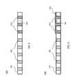
- FIG. 1illustrates a redox flow cell filled with electrolyte solution consistent with embodiments of the present invention.
- FIG. 2illustrates a porous flexible membrane material bonded to a rigid frame consistent with embodiments of the present invention.
- FIG. 3illustrates a bonding site of a porous flexible membrane material and a rigid frame bonded using conventional solvent bonding techniques.
- FIG. 4illustrates an assembly direction for bonding a porous flexible membrane material that has been pre-treated for bonding at its bonding site consistent with embodiments of the present invention.
- FIG. 5illustrates a detailed view of the bonding site of a porous flexible membrane material that has been pre-treated for bonding consistent with embodiments of the present invention.
- FIG. 6illustrates a detailed view of the bonding site of a porous flexible membrane material that has been pre-treated for bonding consistent with embodiments of the present invention.
- FIG. 7illustrates a bonding site of a porous flexible membrane material and a rigid structure bonded using solvent bonding techniques consistent with embodiments of the present invention.
- FIG. 8illustrates a bonding site of porous flexible membrane material and a rigid structure bonded using solvent bonding techniques consistent with embodiments of the present invention.
- FIGS. 9A , 9 B, and 9 Cillustrate bonding between a porous flexible membrane and a rigid frame.
- FIG. 10illustrates a solvent bonding process flow chart consistent with embodiments of the present invention.
- FIG. 1illustrates a reduction-oxidation (redox) flow cell 100 filled with electrolyte solution consistent with some embodiments of the present invention.
- Redox flow cell 100includes two half-cells 108 and 110 separated by porous flexible membrane 106 .
- the porous flexible membranemay be an ion exchange membrane (IEM).
- Half-cells 108 and 110include electrodes 102 and 104 respectively, in contact with an electrolyte such that an anodic reaction occurs at the surface of one of electrodes 102 or 104 and a cathodic reaction occurs at the surface of the other one of electrodes 102 or 104 .
- IEMion exchange membrane
- multiple redox flow cells 100can be electrically coupled (e.g., stacked) either in series to achieve higher voltage, in parallel in order to achieve higher current, or both.
- the electrolyte fluidsflow in parallel to the half cells through a manifold.
- one half-cell (e.g., 108 or 110 ) of redox flow cell 100contains an anolyte and the other half-cell contains a catholyte, the anolyte and catholyte being collectively referred to as electrolytes.
- Reactant electrolytesmay be stored in separate tanks and dispensed into the half-cells 108 and 110 via pipes, tubes, and the like (not shown) coupled to cell input/output (I/O) ports 112 , 114 and 116 , 118 respectively, often using an external pumping system.
- I/Ocell input/output
- At least one electrode 102 and 104 in each half-cell 108 and 110provides a surface on which the redox reaction takes place and from which charge is transferred.
- Redox flow cell 100operates by changing the oxidation state of its constituents during charging or discharging.
- the two half-cells 108 and 110are connected in series by the conductive electrolytes, one for anodic reaction and the other for cathodic reaction.
- electrolytei.e., anolyte or catholyte
- I/O ports 112 , 114 and 116 , 118respectively as the redox reaction takes place.
- Positive ions or negative ionspass through the porous flexible membrane 106 separating the two half-cells 108 and 110 as the redox flow cell 100 charges or discharges.
- Reactant electrolytesare flowed through half-cells 108 and 110 , as necessary, in a controlled manner to supply electrical power or be charged by load/source 124 .
- Porous flexible membrane 106may absorb moisture and expand when placed in an aqueous solution (i.e., wetted). Electrolytes used in flow batteries, for example, can be aqueous solutions of salts.
- porous flexible membranesmay be sheets of woven or non-woven plastic with active ion exchange materials such as resins or functionalities embedded either in a heterogeneous (e.g., co-extrusion) or homogeneous (e.g., radiation grafting) way.
- Porous flexible membrane 106may be a porous flexible membrane having high voltaic efficiency Ev and high coulombic efficiency and may be designed to limit mass transfer through the membrane to a minimum while still facilitating ionic transfer.
- porous flexible membrane 106may be made from a polyolefin (polyalkene) material and may have a specified thickness and pore diameter.
- a manufacturerhaving the capability to manufacture these membranes, and other membranes consistent with embodiments of the present invention, is for example Daramic Microporous Products, L.P., N. Community House Rd., Suite 35, Charlotte, N.C. 28277.
- porous flexible membrane 106may be a non-ion-selective microporous plastic separator also manufactured by Daramic Microporous Products L.P.
- Membranes consistent with embodiments of the present inventioncan be produced by extruding sheets of polyolefin with or without fillers such as silicon dioxide (silica) particles or fibers, and with oil particulates heterogeneously spread throughout the body of the sheet. After the extrusion, the sheet can be treated with a solvent or etchant to remove the oil particles, leaving behind pores. Properties like the thickness, pore size, pore density, and tortuosity are heavily process dependent and are often closely-guarded secrets of the manufacturer. These parameters, however, can be specified to the manufacturer for production. In some embodiments, membranes consistent with embodiments of the present invention can be designed to have an advantageous figure-of-merit (FOM) to improve voltage and coulombic efficiency as discussed in application Ser. No. 12/217,059 to Sahu, filed on Jul. 1, 2008, assigned to the same assignee as the present invention, and herein incorporated by reference in its entirety.
- FOMfigure-of-merit
- the redox reactiontakes place in an aqueous acidic medium.
- the electrolyte in half-cell 108is an acidic solution of FeCl2, forming a cathode side of redox flow cell 100 .
- the electrolyte in half-cell 110is an acidic solution of CrCl3, forming an anode size of redox flow cell 100 . Accordingly, in operation, porous flexible membrane 106 is typically utilized in an aqueous electrolyte solution.
- porous flexible membrane 106may be bonded to a rigid frame.
- the rigid framemay be designed not only to provide support for mounting porous flexible membrane 106 within redox flow cell 100 , but also to provide even spacing between porous flexible membrane 106 and electrodes 102 and 104 within each half-cell 108 and 110 . Providing even spacing between porous flexible membrane 106 and electrodes 102 and 104 optimizes the efficiency of redox flow cell 100 by ensuring an even distribution of electrolyte within half-cells 108 and 110 and equal electrolyte flow resistance through half-cells 108 and 110 .
- porous flexible membrane 106may be bonded to a rigid frame constructed using, for example, polyvinyl chloride (PVC) or poly methyl methacrylate (PMMA) material using solvent bonding.
- the rigid framemay be constructed using other rigid materials capable of being bonded to porous flexible membrane 106 using solvent bonding techniques.
- porous flexible membrane 106is first cleaned and dried such that particulates and/or moisture at the bonding site of porous flexible membrane 106 and the frame are removed. Cleaning and drying the bonding site of porous flexible membrane 106 and the rigid frame optimizes the strength and quality of the bond achieved using solvent bonding techniques.
- a solvent that is capable of dissolving a surface of the rigid frame materiale.g., for a PVC frame, acetone, N,N-dimethylformamide (DMF), methyl ethyl ketone (MEK), and tetrahydrofuran (THF)
- the solvent usedmay be capable of dissolving a surface of the frame material, but be compatible with the porous flexible membrane 106 material. The applied solvent dissolves a surface of the frame material at its bonding site.
- porous flexible membrane 106may be pressed to the rigid frame material.
- a mechanical pressmay be used to press porous flexible membrane 106 to the frame (e.g., a pneumatic press used with a pressure of 10-50 PSI, which is equivalent to about 69-340 kPa).
- a pneumatic pressused with a pressure of 10-50 PSI, which is equivalent to about 69-340 kPa.
- the rigid material and porous flexible membrane 106are bonded (i.e., fused) by way of a surface bond at their bonding sites.
- porous flexible membrane 106may be a porous flexible membrane that absorbs moisture and expands when placed in an aqueous solution (i.e., wetted). Accordingly, if porous flexible membrane 106 is mounted to the rigid frame using conventional solvent bonding techniques in a non-aqueous medium and later wetted, porous flexible membrane 106 may expand and ripple (e.g., become non-planar) within the frame. As porous flexible membrane 106 expands, the spacing between porous flexible membrane 106 and electrodes 102 and 104 within each half-cell 108 - 110 becomes uneven (e.g., distance 120 illustrated in FIG. 1 may differ from distance 122 ). This uneven spacing may cause electrolyte within half-cells 108 and 110 to be unevenly distributed.
- electrolyte flow resistance across each of half-cells 108 and 110may vary.
- electrolyte flow resistance across half-cell 110may be greater at distance 122 than that across distance 120 .
- rippling of porous flexible membrane 106may adversely affect the overall efficiency of redox flow cell 100 if conventional solvent bonding techniques are utilized in mounting porous flexible membrane 106 to a rigid frame. The rippling may also result in cracking or mechanical fatigue when the membrane is assembled in a cell under pressure. Such cracks will result in intra-cellular leaks and adversely affect the efficiency of the system.
- FIG. 2illustrates an assembly 200 , which includes a porous flexible membrane 106 bonded to a rigid frame 202 consistent with some embodiments of the present invention.
- porous flexible membrane 106may be an IEM, and may be the porous flexible membrane 106 utilized in the redox flow cell 100 illustrated in FIG. 1 .
- porous flexible membrane 106may be bonded to a rigid frame 202 .
- rigid frame 202may be constructed using PVC material.
- rigid frame 202may be constructed using other rigid materials capable of being bonded to porous flexible membrane 106 using solvent bonding techniques.
- Rigid frame 202may be designed to provide support for mounting porous flexible membrane 106 within redox flow cell 100 and to ensure that porous flexible membrane 106 and electrodes 102 and 104 are evenly spaced within each half-cell 108 and 110 . Providing even spacing between porous flexible membrane 106 and electrodes 102 and 104 optimizes the efficiency of redox flow cell 100 by ensuring an even distribution of electrolyte within half-cells 108 and 110 and equal electrolyte flow resistance through half-cells 108 and 110 .
- rigid frame 202may be constructed using a single piece of rigid material (e.g., PVC and PMMA). In certain other embodiments, rigid frame 202 may be constructed using multiple pieces of rigid material bonded together and, in certain embodiments, may be bonded to both sides of porous flexible membrane 106 at its bonding site, as discussed below in reference to FIG. 8 .
- FIG. 3is a cross-sectional view 300 of the porous flexible membrane and rigid frame assembly 300 .
- FIG. 3illustrates a bonding site of a porous flexible membrane 106 and a rigid frame 202 bonded using conventional solvent bonding techniques.
- Porous flexible membrane 106includes pores 302 . Although in FIG. 3 simple cylindrical pores are shown, the pores may have various diameters, diameter variations, penetration, and tortuosity.
- porous flexible membrane material 106may be an IEM utilized in the redox flow cell 100 illustrated in FIG. 1 .
- porous flexible membrane 106may be bonded to rigid frame 202 at bonding site 304 .
- Rigid frame 202may be constructed using PVC material, PMMA material, or other rigid materials capable of being bonded to porous flexible membrane 106 using solvent bonding techniques.
- porous flexible membrane 106may be bonded to rigid frame 202 using conventional solvent bonding techniques. Utilizing such techniques, the bonding site 304 of porous flexible membrane 106 may be cleaned and dried prior to bonding such that particulates and/or moisture at bonding site 304 are removed. Cleaning and drying bonding site 304 of porous flexible membrane 106 optimizes the strength and quality of the bond achieved using solvent bonding techniques.
- a solvent that is capable of dissolving a surface of the frame 202 materialis applied to the rigid frame 202 and/or porous flexible membrane 106 at bonding site 304 after bonding site 304 has been cleaned and dried.
- the solvent usedmay be capable of dissolving a surface of rigid frame 202 material, but be compatible with the porous flexible membrane 106 material.
- the applied solventdissolves the rigid frame 202 material at bonding site 304 .
- porous flexible membrane 106may be pressed to rigid frame 202 at bonding site 304 . As the applied solvent evaporates, rigid frame 202 and porous flexible membrane 106 are bonded (i.e., fused) by way of a surface bond at bonding site 304 .
- FIG. 4shows the assembly direction 400 for bonding the porous membrane with the rigid frame.
- FIG. 4illustrates a porous flexible membrane 106 that has been pre-treated for bonding at its bonding site 304 consistent with embodiments of the present invention.
- porous flexible membrane 106may be an IEM utilized in the redox flow cell 100 illustrated in FIG. 1 .
- rigid frame 202may be constructed using PVC material, PMMA material, or other rigid materials capable of being bonded to porous flexible membrane 106 using solvent bonding techniques.
- porous flexible membrane 106may absorb moisture and expand when placed in an aqueous solution. Accordingly, if porous flexible membrane 106 is bonded to rigid frame 202 in a non-aqueous medium (e.g., when porous flexible membrane 106 is bonded using conventional solvent bonding techniques) and later wetted, porous flexible membrane 106 may expand and ripple (i.e., become non-planar) within rigid frame 202 , thereby reducing the overall efficiency of redox flow cell 100 .
- porous flexible membrane 106may be reduced by bonding porous flexible membrane 106 to rigid frame 202 while porous flexible membrane 106 is in a wetted state (e.g., has been placed in an aqueous solution), and, therefore, expanded due to absorption of moisture. If bonded to rigid frame 202 in a wetted state and as porous flexible membrane 106 dries and contracts, porous flexible membrane 106 may remain planar (e.g., drum-like) within rigid frame 202 .
- porous flexible membrane 106When placed in an aqueous solution, porous flexible membrane 106 may expand but will not ripple within rigid frame 202 if porous flexible membrane 106 was bonded to rigid frame 202 in the aforementioned manner (i.e., bonded in a wetted state).
- Solvent bondingideally requires that bonding site 304 between porous flexible membrane 106 and rigid frame 202 be free of particulate matter and moisture prior to bonding. Accordingly, in conventional solvent bonding, as discussed above, porous flexible membrane 106 and rigid frame 202 are often cleaned and dried at bonding site 304 prior to bonding porous flexible membrane 106 and rigid frame 202 in order to achieve the best possible bond. As drying bonding site 304 while simultaneously ensuring that the rest of porous flexible membrane 106 remains in a wetted state is often ineffective, wetting porous flexible membrane 106 prior to bonding porous flexible membrane 106 to rigid frame 202 often proves impracticable.
- a solvent bonding pre-treatmentmay be applied at the bonding site 304 of porous flexible membrane 106 , as shown in FIG. 4 .
- a solvent solution carrying a certain amount of residue materiale.g., polymeric residue
- residue materiale.g., polymeric residue
- a pre-treatment solvent solutione.g., acetone and/or DMF
- a pre-treatment solvent solutionthat includes a certain amount of dissolved PVC residue may be applied to bonding site 304 of porous flexible membrane 106 .
- the PVC residue used to pre-treat bonding site 304may be low molecular weight PVC and/or intermediate molecular weight PVC.
- the pre-treatment solvent solutionmay be applied to the bonding site 304 of porous flexible membrane 106 manually.
- the application of pre-treatment solvent solutionmay also be applied to the bonding site 304 of porous flexible membrane 106 via automated means such as, for example, a computer numerical control (CNC) machine or a machine configured to submerse the edges (e.g., bonding site 304 ) of porous flexible membrane 106 into the pre-treatment solvent solution.
- CNCcomputer numerical control
- the pre-treatment solvent solutionevaporates from bonding site 304 , the residue material (e.g., polymeric residue) carried by the pre-treatment solvent solution remains on porous flexible membrane 106 .
- the residue material dissolved in the pre-treatment solvent solutionmay be arranged such that the dissolved material impregnates pores 302 of porous flexible membrane 106 when the pre-treatment solvent solution is applied. Accordingly, when the pre-treatment solvent solution evaporates, the pores 302 of porous flexible membrane 106 at pre-treated bonding site 304 may be filled with the residue material (e.g., polymeric residue) dissolved in the pre-treatment solvent solution.
- a thin layer of residue materialmay also remain on the surface of porous flexible membrane 106 at pre-treated bonding site 304 after application and drying of the pre-treatment solvent solution.
- pre-treatmentmay be applied multiple times if residue filling in a single step is not sufficient.
- porous flexible membrane 106impregnating the pores 302 of porous flexible membrane 106 with residue material and/or depositing a thin layer of residue material on the surface of porous flexible membrane 106 at pre-treated bonding site 304 causes porous flexible membrane 106 at pre-treated bonding site 304 to be extremely hydrophobic. Accordingly, if wetted, then porous flexible membrane 106 may expand as it absorbs moisture except at pre-treated bonding site 304 .
- the residue material dissolved in the pre-treatment solvent solution impregnating the pores 302 of porous flexible membrane 106may be arranged using soft materials (e.g., low molecular weight and/or intermediate molecular weight PVC), such that the areas of porous flexible membrane 106 at pre-treated bonding site 304 are not adversely affected by the expansion of the non-treated areas of porous flexible membrane 106 .
- soft materialse.g., low molecular weight and/or intermediate molecular weight PVC
- pre-treated bonding site 304is hydrophobic, after wetting porous flexible membrane 106 , pre-treated bonding site 304 may be dried manually or automatically independent of the non-treated areas of porous flexible membrane 106 . While the non-treated areas of porous flexible membrane 106 are in a wetted state, rigid frame 202 may be bonded to porous flexible membrane 106 at the pre-treated bonding site using solvent bonding techniques.
- a solvent that is capable of dissolving a surface of the rigid frame 202 material and the pre-treatment residue material(e.g., for a PVC frame, acetone, DMF, MEK, and THF) is applied at the pre-treated bonding site 304 of porous flexible membrane 106 .
- solvent materialmay also be applied to the corresponding bonding site of rigid frame 202 .
- the applied solventdissolves at least some of the pre-treatment residue material at pre-treated bonding site 304 and/or the rigid frame 202 material at its corresponding bonding site.
- Porous flexible membrane 106may then be pressed to the rigid frame 202 .
- rigid frame 202 and porous flexible membrane 106are bonded (e.g., fused) at pre-treated bonding site 304 by way of a volume bond.
- this bonding techniqueprovides a stronger bond than that obtained using a surface solvent bonding technique.
- porous flexible membrane 106will remain planar within rigid frame 202 .
- porous flexible membrane 106may expand but will not ripple within rigid frame 202 . Accordingly, if integrated into the redox flow cell 100 illustrated in FIG.
- porous flexible membrane 106 bonded to rigid frame 202 using the aforementioned pre-treatment solvent bonding techniquewill remain planar even when submerged in an aqueous electrolyte solution, thereby reducing the problems associated with the rippling of porous flexible membrane 106 within redox flow cell 100 .
- FIG. 5illustrates a detailed view 500 of the bonding site 304 of a porous flexible membrane 106 that has been pre-treated for bonding consistent with embodiments of the present invention.
- Porous flexible membrane 106includes pores 302 .
- porous flexible membrane 106may be an IEM utilized in the redox flow cell 100 illustrated in— FIG. 1 .
- porous flexible membrane 106may be pre-treated at bonding site 304 with a pre-treatment solvent solution. As discussed above, the pre-treatment solvent solution carries a certain amount of dissolved residue material similar to the material used in rigid frame 202 .
- a pre-treatment solvent solutione.g., acetone and/or DMF
- a pre-treatment solvent solutionthat includes a certain amount of dissolved PVC residue may be applied to bonding site 304 of porous flexible membrane 106 .
- the PVC residue used to pre-treat bonding site 304may be a low molecular weight PVC and/or a soft PVC reside.
- the residue material dissolved in the pre-treatment solvent solutionmay be arranged such that the dissolved material impregnates the pores of porous flexible membrane 106 when the pre-treatment solvent solution is applied.
- pores 502 at bonding site 304may be filled with the dissolved residue material.
- the residue materialremains in pores 502 .
- FIG. 6illustrates a detailed view 600 of the bonding site 304 of a porous flexible membrane material 106 that has been pre-treated for bonding consistent with embodiments of the present invention.
- Porous flexible membrane 106includes pores 302 .
- porous flexible membrane 106may be an IEM utilized in redox flow cell illustrated in FIG. 1 .
- porous flexible membrane 106may be pre-treated at bonding site 304 with a pre-treatment solvent solution.
- the residue material dissolved in the pre-treatment solvent solutionmay be arranged such that the dissolved material impregnates the pores of porous flexible membrane 106 when the pre-treatment solvent solution is applied.
- pores 602may be filled with the dissolved residue material.
- the residue materialremains in pores 602 .
- a thin layer 604 of residue materialmay also remain on the surface of porous flexible membrane 106 at pre-treated bonding site 304 after application and drying of the pre-treatment solvent solution. While FIG.
- FIG. 6only illustrates a single layer 604 deposited on one side of porous flexible membrane 106 , in certain embodiments a second thin layer may also be deposited on the opposite side of porous flexible membrane 106 , thereby created two bonding sites 304 on either side of porous flexible membrane 106 .
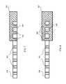
- FIG. 7illustrates a bonding site 304 of a porous flexible membrane material 106 and a rigid frame 202 bonded using solvent bonding techniques consistent with embodiments of the present invention.
- Porous flexible membrane 106includes pores 302 .
- porous flexible membrane 106may be an IEM utilized in the redox flow cell 100 illustrated in FIG. 1 .
- rigid frame 202may be a rigid frame constructed using PVC material.
- rigid frame 202may be constructed using other rigid materials capable of being bonded to porous flexible membrane 106 using solvent bonding techniques consistent with embodiments of the present invention.
- porous flexible membrane 106is bonded to rigid frame 202 at bonding site 304 .
- bonding site 304may be pre-treated with a pre-treatment solvent solution.
- a pre-treatment bonding solvent solutionmay carry a certain amount of dissolved residue material similar to the material used in rigid frame 202 .
- a pre-treatment solvent solutione.g., acetone and/or DMF
- the PVC residue used to pre-treat the bonding site 304may be a low molecular weight PVC and/or a soft PVC residue.
- the residue material dissolved in the pre-treatment solvent solutionmay be arranged such that the dissolved material impregnates the pores 302 of porous flexible membrane 106 when the pre-treatment solvent solution is applied.
- pores 702 at bonding site 304may be filled with the dissolved residue material.
- the residue materialremains in pores 702 .
- a thin layer of residue materialmay also remain on the surface of porous flexible membrane 106 at the pre-treated bonding site 304 after application and drying of the pre-treatment solvent solution.
- Porous flexible membrane 106is bonded at its pre-treated bonding site 304 to rigid frame 202 using a solvent bonding techniques consistent with embodiments of the present invention.
- a solvent that is capable of dissolving a surface of the rigid frame 202 material and the pre-treatment residue materiale.g., acetone and/or DMF in the context of a PVC frame and PVC residue material
- solvent materialmay also be applied to the corresponding bonding site of rigid frame 202 .
- the applied solventdissolves at least some of the pre-treatment residue material at pre-treated bonding site 304 and/or the rigid frame 202 material at its corresponding bonding site. Porous flexible membrane 106 may then be pressed to the rigid frame 202 . As the applied solvent evaporates, rigid frame 202 and porous flexible membrane 106 are bonded (e.g., fused) at pre-treated bonding site 304 . As shown in FIG. 7 , because the pre-treatment residue material and the rigid frame 202 material are similar, a strong volume bond between porous flexible membrane 106 and rigid frame 202 is created when porous flexible membrane 106 and rigid frame 202 are bonded using solvent bonding techniques consistent with embodiments of the present invention. In some embodiments, this volume bond proves especially effective against damage to the bond caused by shearing forces.
- FIG. 8illustrates a bonding site 304 of a porous flexible membrane material 106 and a rigid frame 202 bonded using solvent bonding techniques consistent with embodiments of the present invention.
- Porous flexible membrane 106includes pores 302 .
- porous flexible membrane 106may be an IEM utilized in the redox flow cell 100 illustrated in FIG. 1 .
- rigid frame 202may be a rigid frame construed using PVC material.
- rigid frame 202may be constructed using other rigid materials capable of being bonded to porous flexible membrane 106 using solvent bonding techniques consistent with embodiments of the present invention.
- rigid frame 202may be bonded to porous flexible membrane 106 using the aforementioned pre-treatment solvent bonding techniques.
- Pre-treatment residue materialmay be deposited within pores 802 at bonding site 304 .
- a solvent that is capable of dissolving a surface of the rigid frame 202 material and the pre-treatment residue materialis applied at the pre-treated bonding site 304 of porous flexible membrane 106 .
- solvent materialmay also be applied to the corresponding bonding sites on rigid frame 202 .
- Porous flexible membrane 106is pressed to rigid frame 202 at the corresponding bonding sites 304 . As shown in FIG.
- a strong volume bond between porous flexible membrane 106 and rigid frame 202may be created as rigid frame 202 is bonded to both sides of porous flexible membrane 106 .
- this volume bondproves especially effective against damage to the bond caused by shearing forces.
- FIG. 9Aillustrates a rigid frame 930 and porous flexible membrane 910 having pores 920 prior to bonding.
- FIG. 9Billustrates a rigid frame 930 and porous flexible membrane 910 bonded together with conventional solvent bonding.
- Conventional solvent bondingfuses two materials together at a molecular level (e.g., PVC-PVC bond using DMF).
- the porous flexible membrane 910is not soluble in the solvent (e.g., PVC frame and polyethylene membrane)
- the bondis established, because the residue 940 in the pores 920 solidifies into a continuous material with the residue material 950 and PVC frame 930 .
- the porous flexible membrane 910is held in place by friction. Such a bond is not at a molecular level.
- FIG. 9Cillustrates a rigid frame 930 and porous flexible membrane 910 bonded together with a volume bonding technique.
- the tortuosity of the pores 920gives rise to tortuous residue columns 960 in the porous flexible membrane 910 which are molecularly bonded to the residue material 950 and frame 930 .
- Such formationsfurther increase the frictional attachment 970 of the rigid frame 930 and porous flexible membrane 910 .
- the resulting frictional forcesresist delamination of the rigid frame 930 and porous flexible membrane 910 .
- the volume bonding techniqueis discussed in further detail with reference to FIGS. 5-8 .
- FIG. 10illustrates a solvent bonding process flow chart 1000 consistent with embodiments of the present invention.
- bonding sites 304 of porous flexible membrane 106may be pre-treated with a pre-treatment solvent solution carrying dissolved residue material similar to the material used to construct frame 202 and arranged to impregnate the ports of porous membrane 106 at bonding site 304 .
- the porous flexible membrane 106may be placed in an aqueous solution (i.e., wetted).
- Porous flexible membrane 106may expand as it absorbs moisture from the aqueous solution. Once expanded, at step 1006 , pre-treated bonding sites 304 may be dried. Because the pre-treatment process makes pre-treated bonding sites 304 extremely hydrophobic, pre-treated bonding sites 304 may be dried independently of the untreated areas of porous flexible membrane 106 .
- pre-treated porous flexible membrane 106may be bonded to the rigid frame (e.g., PVC frame) 202 using solvent bonding techniques consistent with embodiments of the invention.
- the porous flexible membrane 106may be dried. Because porous flexible membrane 106 was bonded to frame 202 while in a wetted state (e.g., expanded state), when porous flexible membrane 106 within frame 202 is placed in an aqueous solution and expanded, porous flexible membrane 106 will not ripple. In this manner, inefficiencies attributed by rippled IEMs in redox flow cells may be reduced by constructing IEMs using bonding techniques consistent with the present invention.
Landscapes
- Chemical & Material Sciences (AREA)
- Chemical Kinetics & Catalysis (AREA)
- Life Sciences & Earth Sciences (AREA)
- Engineering & Computer Science (AREA)
- Manufacturing & Machinery (AREA)
- Sustainable Development (AREA)
- Sustainable Energy (AREA)
- Electrochemistry (AREA)
- General Chemical & Material Sciences (AREA)
- Fuel Cell (AREA)
Abstract
Description
Claims (10)
Priority Applications (1)
| Application Number | Priority Date | Filing Date | Title |
|---|---|---|---|
| US12/577,131US8883297B2 (en) | 2008-10-10 | 2009-10-09 | Methods for bonding porous flexible membranes using solvent |
Applications Claiming Priority (2)
| Application Number | Priority Date | Filing Date | Title |
|---|---|---|---|
| US10461108P | 2008-10-10 | 2008-10-10 | |
| US12/577,131US8883297B2 (en) | 2008-10-10 | 2009-10-09 | Methods for bonding porous flexible membranes using solvent |
Publications (2)
| Publication Number | Publication Date |
|---|---|
| US20100092757A1 US20100092757A1 (en) | 2010-04-15 |
| US8883297B2true US8883297B2 (en) | 2014-11-11 |
Family
ID=42099113
Family Applications (1)
| Application Number | Title | Priority Date | Filing Date |
|---|---|---|---|
| US12/577,131Expired - Fee RelatedUS8883297B2 (en) | 2008-10-10 | 2009-10-09 | Methods for bonding porous flexible membranes using solvent |
Country Status (2)
| Country | Link |
|---|---|
| US (1) | US8883297B2 (en) |
| WO (1) | WO2010042900A1 (en) |
Families Citing this family (30)
| Publication number | Priority date | Publication date | Assignee | Title |
|---|---|---|---|---|
| US8587150B2 (en)* | 2008-02-28 | 2013-11-19 | Deeya Energy, Inc. | Method and modular system for charging a battery |
| US7927731B2 (en)* | 2008-07-01 | 2011-04-19 | Deeya Energy, Inc. | Redox flow cell |
| US7820321B2 (en)* | 2008-07-07 | 2010-10-26 | Enervault Corporation | Redox flow battery system for distributed energy storage |
| US8785023B2 (en)* | 2008-07-07 | 2014-07-22 | Enervault Corparation | Cascade redox flow battery systems |
| US8230736B2 (en)* | 2008-10-10 | 2012-07-31 | Deeya Energy, Inc. | Level sensor for conductive liquids |
| WO2010042899A1 (en)* | 2008-10-10 | 2010-04-15 | Deeya Energy Technology, Inc. | Flexible multi-walled tubing assembly |
| EP2351184A4 (en)* | 2008-10-10 | 2014-07-09 | Deeya Energy Technologies Inc | Method and apparatus for determining state of charge of a battery |
| US8883297B2 (en) | 2008-10-10 | 2014-11-11 | Imergy Power Systems, Inc. | Methods for bonding porous flexible membranes using solvent |
| US20100092843A1 (en)* | 2008-10-10 | 2010-04-15 | Deeya Energy Technologies, Inc. | Venturi pumping system in a hydrogen gas circulation of a flow battery |
| US8236463B2 (en)* | 2008-10-10 | 2012-08-07 | Deeya Energy, Inc. | Magnetic current collector |
| WO2010138942A2 (en) | 2009-05-28 | 2010-12-02 | Deeya Energy, Inc. | Redox flow cell rebalancing |
| CN102460812B (en)* | 2009-05-28 | 2014-12-31 | 艾默吉电力系统股份有限公司 | Preparation of flow battery electrolytes from raw materials |
| EP2436080A2 (en)* | 2009-05-28 | 2012-04-04 | Deeya Energy, Inc. | Electrolyte compositions |
| WO2010138948A2 (en)* | 2009-05-28 | 2010-12-02 | Deeya Energy, Inc. | Buck-boost control circuit |
| US8587255B2 (en) | 2009-05-28 | 2013-11-19 | Deeya Energy, Inc. | Control system for a flow cell battery |
| WO2010138949A2 (en)* | 2009-05-28 | 2010-12-02 | Deeya Energy, Inc. | Optical leak detection sensor |
| WO2010138947A2 (en)* | 2009-05-29 | 2010-12-02 | Deeya Energy, Inc. | Methods of producing hydrochloric acid from hydrogen gas and chlorine gas |
| US8951665B2 (en)* | 2010-03-10 | 2015-02-10 | Imergy Power Systems, Inc. | Methods for the preparation of electrolytes for chromium-iron redox flow batteries |
| AT510250A1 (en)* | 2010-07-21 | 2012-02-15 | Cellstrom Gmbh | FRAME OF A CELL OF A REDOX FLOW BATTERY |
| US9281535B2 (en) | 2010-08-12 | 2016-03-08 | Imergy Power Systems, Inc. | System dongle |
| US8541121B2 (en) | 2011-01-13 | 2013-09-24 | Deeya Energy, Inc. | Quenching system |
| US9106980B2 (en) | 2011-01-13 | 2015-08-11 | Imergy Power Systems, Inc. | Communications system |
| US9269982B2 (en) | 2011-01-13 | 2016-02-23 | Imergy Power Systems, Inc. | Flow cell stack |
| US8980484B2 (en) | 2011-03-29 | 2015-03-17 | Enervault Corporation | Monitoring electrolyte concentrations in redox flow battery systems |
| US8916281B2 (en) | 2011-03-29 | 2014-12-23 | Enervault Corporation | Rebalancing electrolytes in redox flow battery systems |
| US9685651B2 (en) | 2012-09-05 | 2017-06-20 | Ess Tech, Inc. | Internally manifolded flow cell for an all-iron hybrid flow battery |
| WO2014039731A1 (en) | 2012-09-05 | 2014-03-13 | Energy Storage Systems, Inc. | Redox and plating electrode systems for an all-iron hybrid flow battery |
| LU92934B1 (en)* | 2015-12-24 | 2017-07-21 | Hurrah Sarl | Porous membrane and method of production thereof |
| DE102016201002B4 (en)* | 2016-01-25 | 2019-03-28 | Ferrumio Gmbh | Process for the preparation of at least one component of a prosthesis and a correspondingly produced prosthesis component |
| CN110429228B (en)* | 2019-08-15 | 2022-04-19 | 宁德卓高新材料科技有限公司 | Preparation method of composite diaphragm with high-cohesiveness polymer coating film |
Citations (124)
| Publication number | Priority date | Publication date | Assignee | Title |
|---|---|---|---|---|
| US3540934A (en) | 1967-07-11 | 1970-11-17 | Jan Boeke | Multiple cell redox battery |
| US3996064A (en) | 1975-08-22 | 1976-12-07 | The United States Of America As Represented By The Administrator Of The National Aeronautics And Space Administration | Electrically rechargeable REDOX flow cell |
| US4133941A (en) | 1977-03-10 | 1979-01-09 | The United States Of America As Represented By The Administrator Of The National Aeronautics And Space Administration | Formulated plastic separators for soluble electrode cells |
| US4159366A (en) | 1978-06-09 | 1979-06-26 | The United States Of America As Represented By The Administrator Of The National Aeronautics And Space Administration | Electrochemical cell for rebalancing redox flow system |
| US4309372A (en) | 1977-03-10 | 1982-01-05 | The United States Of America As Represented By The Administrator Of The National Aeronautics And Space Administration | Method of making formulated plastic separators for soluble electrode cells |
| US4312735A (en) | 1979-11-26 | 1982-01-26 | Exxon Research & Engineering Co. | Shunt current elimination |
| US4414090A (en) | 1981-10-01 | 1983-11-08 | Rai Research Corporation | Separator membranes for redox-type electrochemical cells |
| US4454649A (en) | 1982-02-26 | 1984-06-19 | The United States Of America As Represented By The Administrator Of The National Aeronautics And Space Administration | Chromium electrodes for REDOX cells |
| US4468441A (en) | 1981-10-01 | 1984-08-28 | Rai Research Corp. | Separator membranes for redox-type electrochemical cells |
| US4485154A (en) | 1981-09-08 | 1984-11-27 | Institute Of Gas Technology | Electrically rechargeable anionically active reduction-oxidation electrical storage-supply system |
| US4496637A (en) | 1982-12-27 | 1985-01-29 | Toyo Boseki Kabushiki Kaisha | Electrode for flowcell |
| JPS6047373A (en) | 1983-08-26 | 1985-03-14 | Sumitomo Electric Ind Ltd | redox battery |
| JPS6070672A (en) | 1983-09-26 | 1985-04-22 | Agency Of Ind Science & Technol | Method of operating redox-flow secondary battery |
| JPS60115174A (en) | 1983-11-25 | 1985-06-21 | Mitsui Eng & Shipbuild Co Ltd | Method of preparing solution for redox-flow battery |
| US4543302A (en) | 1984-08-20 | 1985-09-24 | The United States Of America As Represented By The Administrator Of The National Aeronautics And Space Administration | Negative electrode catalyst for the iron chromium REDOX energy storage system |
| US4732827A (en) | 1985-07-05 | 1988-03-22 | Japan Metals And Chemical Co., Ltd. | Process for producing electrolyte for redox cell |
| US4784924A (en) | 1981-06-08 | 1988-11-15 | University Of Akron | Metal-halogen energy storage device and system |
| US4814241A (en) | 1986-03-15 | 1989-03-21 | Director-General, Agency Of Industrial Science And Technology | Electrolytes for redox flow batteries |
| US4828666A (en) | 1987-02-16 | 1989-05-09 | Toyo Boseki Kabushiki Kaisha (Trading Under Toyo Co., Ltd.) | Electrode for flow-through type electrolytic cell |
| WO1989005528A1 (en) | 1987-12-10 | 1989-06-15 | Unisearch Limited | Vanadium charging cell and vanadium dual battery system |
| US4849311A (en) | 1986-09-24 | 1989-07-18 | Toa Nenryo Kogyo Kabushiki Kaisha | Immobilized electrolyte membrane |
| US4874483A (en) | 1988-02-04 | 1989-10-17 | Chiyoda Corporation | Process for the preparation of redox battery electrolyte and recovery of lead chloride |
| US4882241A (en) | 1987-10-23 | 1989-11-21 | Siemens Aktiengesellschaft | Redox battery |
| JPH01320776A (en) | 1988-06-23 | 1989-12-26 | Nkk Corp | Redox flow type battery |
| US4894294A (en) | 1984-06-05 | 1990-01-16 | The Furukawa Electric Co., Ltd. | Electrolytic solution supply type battery |
| JPH0227668A (en) | 1988-07-18 | 1990-01-30 | Sumitomo Electric Ind Ltd | How to maintain battery capacity of redox flow battery |
| JPH0227667A (en) | 1988-07-18 | 1990-01-30 | Sumitomo Electric Ind Ltd | Redox flow battery with electrolyte regeneration device and its battery capacity maintenance method |
| WO1990003666A1 (en) | 1988-09-23 | 1990-04-05 | Unisearch Limited | State of charge of redox cell |
| US4929325A (en) | 1988-09-08 | 1990-05-29 | Globe-Union Inc. | Removable protective electrode in a bipolar battery |
| US4945019A (en) | 1988-09-20 | 1990-07-31 | Globe-Union Inc. | Friction welded battery component |
| US4948681A (en) | 1988-05-02 | 1990-08-14 | Globe-Union Inc. | Terminal electrode |
| US4956244A (en) | 1988-06-03 | 1990-09-11 | Sumitomo Electric Industries, Ltd. | Apparatus and method for regenerating electrolyte of a redox flow battery |
| JPH0317963A (en) | 1989-06-14 | 1991-01-25 | Sumitomo Electric Ind Ltd | Redox flow batteries and how to measure the depth of charge and discharge of redox flow batteries |
| US5026479A (en) | 1990-02-13 | 1991-06-25 | Union Carbide Industrial Gases Technology Corporation | Fluid separation device |
| US5061578A (en) | 1985-10-31 | 1991-10-29 | Kabushiki Kaisha Meidensha | Electrolyte circulation type secondary battery operating method |
| US5126054A (en) | 1990-05-24 | 1992-06-30 | Pall Corporation | Venting means |
| US5162168A (en) | 1991-08-19 | 1992-11-10 | Magnavox Electronic Systems Company | Automatic voltage control system and method for forced electrolyte flow batteries |
| US5188911A (en) | 1991-02-25 | 1993-02-23 | Magnavox Electronic Systems Company | Tapered manifold for batteries requiring forced electrolyte flow |
| WO1993006626A1 (en) | 1991-09-17 | 1993-04-01 | Unisearch Limited | Permeation selective separators and processes for making such separators |
| US5258241A (en) | 1988-12-22 | 1993-11-02 | Siemens Aktiengesellschaft | Rebalance cell for a Cr/Fe redox storage system |
| US5366824A (en) | 1992-10-21 | 1994-11-22 | Agency Of Industrial Science & Technology, Ministry Of International Trade & Industry | Flow battery |
| US5447636A (en)* | 1993-12-14 | 1995-09-05 | E. I. Du Pont De Nemours And Company | Method for making reinforced ion exchange membranes |
| JPH087913A (en) | 1994-06-22 | 1996-01-12 | Kashima Kita Kyodo Hatsuden Kk | Full vanadium redox cell |
| US5648184A (en) | 1995-04-13 | 1997-07-15 | Toyo Boseki Kabushiki Kaisha | Electrode material for flow-through type electrolytic cell, wherein the electrode comprises carbonaceous material having at least one groove |
| US5656390A (en) | 1995-02-16 | 1997-08-12 | Kashima-Kita Electric Power Corporation | Redox battery |
| US5665212A (en) | 1992-09-04 | 1997-09-09 | Unisearch Limited Acn 000 263 025 | Flexible, conducting plastic electrode and process for its preparation |
| JPH1012260A (en) | 1996-06-19 | 1998-01-16 | Kashimakita Kyodo Hatsuden Kk | Redox flow battery |
| JPH1060967A (en) | 1996-08-19 | 1998-03-03 | Sumitomo Forestry Co Ltd | Draining structure |
| US5759711A (en) | 1996-02-19 | 1998-06-02 | Kashima-Kita Electric Power Corporation | Liquid-circulating battery |
| JPH10208766A (en) | 1997-01-27 | 1998-08-07 | Sumitomo Electric Ind Ltd | Redox flow battery |
| US5851694A (en) | 1996-06-19 | 1998-12-22 | Kashima-Kita Electric Power Corporation | Redox flow type battery |
| US5854327A (en) | 1997-06-27 | 1998-12-29 | Bridgestone/Firestone, Inc. | Mineral-filled roofing membrane compositions and uses therefor |
| US5919330A (en) | 1993-03-24 | 1999-07-06 | Pall Corporation | Method for bonding a porous medium to a substrate |
| JPH11329474A (en) | 1998-05-19 | 1999-11-30 | Mitsui Eng & Shipbuild Co Ltd | Redox battery or redox capacitor and method of manufacturing the same |
| US6005183A (en) | 1995-12-20 | 1999-12-21 | Ebara Corporation | Device containing solar cell panel and storage battery |
| JP2000058099A (en) | 1998-08-04 | 2000-02-25 | Sumitomo Electric Ind Ltd | Redox flow battery diaphragm |
| JP3017963B2 (en) | 1997-09-12 | 2000-03-13 | 株式会社三五 | Silencer |
| US6040075A (en) | 1994-12-17 | 2000-03-21 | Loughborough University Of Technology | Electrolytic and fuel cell arrangements |
| US6086643A (en) | 1995-12-28 | 2000-07-11 | National Power Plc | Method for the fabrication of electrochemical cells |
| JP2000200619A (en) | 1999-01-08 | 2000-07-18 | Kashimakita Kyodo Hatsuden Kk | Redox battery |
| US6225368B1 (en) | 1998-09-15 | 2001-05-01 | National Power Plc | Water based grafting |
| US20010017188A1 (en)* | 1996-04-10 | 2001-08-30 | Cooley Graham Edward | Process for the fabrication of electrochemical cell components |
| JP2002015762A (en) | 2000-06-28 | 2002-01-18 | Sumitomo Electric Ind Ltd | Redox flow battery |
| JP2002175822A (en) | 2000-12-07 | 2002-06-21 | Sumitomo Electric Ind Ltd | Redox flow battery and method of operating the same |
| JP2002289233A (en) | 2001-03-23 | 2002-10-04 | Hitachi Zosen Corp | Redox flow battery tank |
| US6461772B1 (en) | 1998-12-14 | 2002-10-08 | Sumitomo Electric Industries, Ltd. | Battery diaphragm |
| US6475661B1 (en) | 1998-01-28 | 2002-11-05 | Squirrel Holdings Ltd | Redox flow battery system and cell stack |
| JP2002367661A (en) | 2001-06-12 | 2002-12-20 | Sumitomo Electric Ind Ltd | Assembling method of redox flow battery |
| US20030008203A1 (en) | 2001-07-05 | 2003-01-09 | Rick Winter | Leak sensor for flowing electrolyte batteries |
| WO2003005476A1 (en) | 2001-07-02 | 2003-01-16 | Funktionswerkstoffe Forschungs- U. Entwicklungs Gmbh | Charging or discharging station for a redox flow battery |
| US6509119B1 (en) | 1999-06-11 | 2003-01-21 | Toyo Boseki Kabushiki Kaisha | Carbon electrode material for a vanadium-based redox-flow battery |
| US6524452B1 (en) | 1998-09-29 | 2003-02-25 | Regenesys Technologies Limited | Electrochemical cell |
| US6555267B1 (en) | 1999-07-01 | 2003-04-29 | Squirrel Holding Ltd. | Membrane-separated, bipolar multicell electrochemical reactor |
| US6562514B1 (en) | 1993-11-17 | 2003-05-13 | Pinnacle Vrb Limited | Stabilized vanadium electrolyte solutions for all-vanadium redox cells and batteries |
| US20030113633A1 (en)* | 2000-05-22 | 2003-06-19 | Yoshifumi Nishimura | Separator for zinc/bromine secondary batteries and production process thereof |
| JP2003173812A (en) | 2001-12-04 | 2003-06-20 | Sumitomo Electric Ind Ltd | Redox flow battery capacity drop detection method |
| US6692862B1 (en) | 2000-03-31 | 2004-02-17 | Squirrel Holdings Ltd. | Redox flow battery and method of operating it |
| US6759158B2 (en) | 2002-01-03 | 2004-07-06 | Premium Power Corporation | System for proclusion of electrical shorting |
| US6761945B1 (en) | 1999-04-28 | 2004-07-13 | Sumitomo Electric Industries, Ltd. | Electrolyte tank and manufacturing method thereof |
| US6764789B1 (en) | 1999-09-27 | 2004-07-20 | Sumitomo Electric Industries, Ltd. | Redox flow battery |
| US20040170893A1 (en) | 2001-06-12 | 2004-09-02 | Hiroyuki Nakaishi | Cell frame for redox flow cell and redox flow cell |
| US20040202915A1 (en) | 2001-06-12 | 2004-10-14 | Hiroyuki Nakaishi | Cell frame for redox-flow cell and redox-flow cell |
| US20040241544A1 (en) | 2001-06-12 | 2004-12-02 | Hiroyuki Nakaishi | Cell stack for flow cell |
| WO2004079849A8 (en) | 2003-03-04 | 2005-03-31 | Squirrel Holdings Ltd | Multi voltage tap redox flow battery composed of stacked cell modules of adjustable cell area |
| US20050074653A1 (en) | 2001-06-28 | 2005-04-07 | Squirrel Holdings Ltd. | Redox cell with non-selective permionic separator |
| JP2005142056A (en) | 2003-11-07 | 2005-06-02 | Kansai Electric Power Co Inc:The | Redox flow battery system |
| US6905797B2 (en) | 2001-04-12 | 2005-06-14 | Squirrel Holdings Ltd. | Porous mat electrodes for electrochemical reactor having electrolyte solution distribution channels |
| US20050158615A1 (en) | 2002-02-14 | 2005-07-21 | Samuel John M.G. | Redox flow battery |
| US20050156431A1 (en) | 2004-01-15 | 2005-07-21 | Hennessy Timothy D.J. | Vanadium redox battery energy storage and power generation system incorporating and optimizing diesel engine generators |
| US20050156432A1 (en) | 2004-01-15 | 2005-07-21 | Hennessy Timothy D.J. | Power generation system incorporating a vanadium redox battery and a direct current wind turbine generator |
| US20050164075A1 (en) | 2002-04-23 | 2005-07-28 | Takahiro Kumamoto | Method for operating redox flow battery and redox flow battery cell stack |
| US20050181273A1 (en) | 2002-04-23 | 2005-08-18 | Hiroshige Deguchi | Method for designing redox flow battery system |
| JP2005228622A (en) | 2004-02-13 | 2005-08-25 | Sumitomo Electric Ind Ltd | Redox flow battery cell |
| JP2005228633A (en) | 2004-02-13 | 2005-08-25 | Sumitomo Electric Ind Ltd | Redox flow battery cell and redox flow battery |
| JP2005322447A (en) | 2004-05-06 | 2005-11-17 | Kansai Electric Power Co Inc:The | Operation method of redox flow battery system |
| US20050260473A1 (en) | 2004-05-21 | 2005-11-24 | Sarnoff Corporation | Electrical power source designs and components |
| US6986966B2 (en) | 2001-08-10 | 2006-01-17 | Plurion Systems, Inc. | Battery with bifunctional electrolyte |
| JP2006114360A (en) | 2004-10-14 | 2006-04-27 | Kansai Electric Power Co Inc:The | Operation method of redox flow battery system |
| JP2006147376A (en) | 2004-11-19 | 2006-06-08 | Kansai Electric Power Co Inc:The | Redox flow battery |
| JP2006147306A (en) | 2004-11-18 | 2006-06-08 | Sumitomo Electric Ind Ltd | Operation method of redox flow battery system |
| US7061205B2 (en) | 2002-04-23 | 2006-06-13 | Sumitomo Electric Industries, Ltd. | Method for operating redox flow battery system |
| US7078123B2 (en) | 1995-05-03 | 2006-07-18 | Vrb Power Systems, Inc. | High energy density vanadium electrolyte solutions, methods of preparation thereof and all-vanadium redox cells and batteries containing high energy vanadium electrolyte solutions |
| DE102006007206A1 (en) | 2006-02-15 | 2006-10-12 | Henze, Werner | Redox battery for power supply has chambers containing electrolytes that are separated by special wall, where wall acting as electrically conducting intermediate electrode is permeable only for hydrogen |
| JP2006313691A (en) | 2005-05-09 | 2006-11-16 | Sumitomo Electric Ind Ltd | Redox flow battery system |
| JP2006351346A (en) | 2005-06-15 | 2006-12-28 | Kansai Electric Power Co Inc:The | Redox flow battery system |
| WO2006135958A1 (en) | 2005-06-20 | 2006-12-28 | V-Fuel Pty Ltd | Improved perfluorinated membranes and improved electrolytes for redox cells and batteries |
| US20070072067A1 (en) | 2005-09-23 | 2007-03-29 | Vrb Power Systems Inc. | Vanadium redox battery cell stack |
| US7199550B2 (en) | 2001-05-01 | 2007-04-03 | Sumitomo Electric Industries, Ltd. | Method of operating a secondary battery system having first and second tanks for reserving electrolytes |
| JP2007087829A (en) | 2005-09-22 | 2007-04-05 | Sumitomo Electric Ind Ltd | Redox flow battery system |
| US20070080666A1 (en) | 2005-10-10 | 2007-04-12 | General Electric Company | Methods and apparatus for coupling an energy storage system to a variable energy supply system |
| US20070111089A1 (en) | 2005-08-30 | 2007-05-17 | Railpower Technologies Corp. | Electrochemical cell for hybrid electric vehicle applications |
| US7220515B2 (en) | 2000-12-06 | 2007-05-22 | Sumitomo Electric Industries, Ltd. | Pressure fluctuation prevention tank structure, electrolyte circulation type secondary battery, and redox flow type secondary battery |
| US7227275B2 (en) | 2005-02-01 | 2007-06-05 | Vrb Power Systems Inc. | Method for retrofitting wind turbine farms |
| US20080193828A1 (en) | 2007-02-12 | 2008-08-14 | Saroj Kumar Sahu | Apparatus and Methods of Determination of State of Charge in a Redox Flow Battery |
| US20090218984A1 (en) | 2008-02-28 | 2009-09-03 | Deeya Energy, Inc. | Battery charger |
| US20100003586A1 (en) | 2008-07-01 | 2010-01-07 | Deeya Energy, Inc. A California C-Corp | Redox flow cell |
| US20100094468A1 (en) | 2008-10-10 | 2010-04-15 | Deeya Energy, Incorporated | Level Sensor for Conductive Liquids |
| US20100092843A1 (en) | 2008-10-10 | 2010-04-15 | Deeya Energy Technologies, Inc. | Venturi pumping system in a hydrogen gas circulation of a flow battery |
| US20100092813A1 (en) | 2008-10-10 | 2010-04-15 | Saroj Kumar Sahu | Thermal Control of a Flow Cell Battery |
| US20100092757A1 (en) | 2008-10-10 | 2010-04-15 | Deeya Energy Technologies, Inc. | Methods for Bonding Porous Flexible Membranes Using Solvent |
| US20100090651A1 (en) | 2008-10-10 | 2010-04-15 | Deeya Energy Technologies, Inc. | Method and apparatus for determining state of charge of a battery |
| US20100092807A1 (en) | 2008-10-10 | 2010-04-15 | Saroj Kumar Sahu | Magnetic Current Collector |
| US20100136455A1 (en) | 2008-10-10 | 2010-06-03 | Rick Winter | Common Module Stack Component Design |
| US20100143781A1 (en) | 2008-12-05 | 2010-06-10 | Majid Keshavarz | Methods for the preparation and purification of electrolytes for redox flow batteries |
Family Cites Families (3)
| Publication number | Priority date | Publication date | Assignee | Title |
|---|---|---|---|---|
| US2004200A (en)* | 1931-10-02 | 1935-06-11 | Union Switch & Signal Co | Lamp socket adapter |
| DE69632422T2 (en)* | 1995-08-11 | 2005-05-19 | Zenon Environmental Inc., Oakville | Process for embedding hollow fiber membranes |
| US7512583B2 (en)* | 2005-05-03 | 2009-03-31 | Palomar Technology, Llc | Trusted decision support system and method |
- 2009
- 2009-10-09USUS12/577,131patent/US8883297B2/ennot_activeExpired - Fee Related
- 2009-10-09WOPCT/US2009/060281patent/WO2010042900A1/enactiveApplication Filing
Patent Citations (126)
| Publication number | Priority date | Publication date | Assignee | Title |
|---|---|---|---|---|
| US3540934A (en) | 1967-07-11 | 1970-11-17 | Jan Boeke | Multiple cell redox battery |
| US3996064A (en) | 1975-08-22 | 1976-12-07 | The United States Of America As Represented By The Administrator Of The National Aeronautics And Space Administration | Electrically rechargeable REDOX flow cell |
| US4133941A (en) | 1977-03-10 | 1979-01-09 | The United States Of America As Represented By The Administrator Of The National Aeronautics And Space Administration | Formulated plastic separators for soluble electrode cells |
| US4309372A (en) | 1977-03-10 | 1982-01-05 | The United States Of America As Represented By The Administrator Of The National Aeronautics And Space Administration | Method of making formulated plastic separators for soluble electrode cells |
| US4159366A (en) | 1978-06-09 | 1979-06-26 | The United States Of America As Represented By The Administrator Of The National Aeronautics And Space Administration | Electrochemical cell for rebalancing redox flow system |
| US4312735A (en) | 1979-11-26 | 1982-01-26 | Exxon Research & Engineering Co. | Shunt current elimination |
| US4784924A (en) | 1981-06-08 | 1988-11-15 | University Of Akron | Metal-halogen energy storage device and system |
| US4485154A (en) | 1981-09-08 | 1984-11-27 | Institute Of Gas Technology | Electrically rechargeable anionically active reduction-oxidation electrical storage-supply system |
| US4468441A (en) | 1981-10-01 | 1984-08-28 | Rai Research Corp. | Separator membranes for redox-type electrochemical cells |
| US4414090A (en) | 1981-10-01 | 1983-11-08 | Rai Research Corporation | Separator membranes for redox-type electrochemical cells |
| US4454649A (en) | 1982-02-26 | 1984-06-19 | The United States Of America As Represented By The Administrator Of The National Aeronautics And Space Administration | Chromium electrodes for REDOX cells |
| US4496637A (en) | 1982-12-27 | 1985-01-29 | Toyo Boseki Kabushiki Kaisha | Electrode for flowcell |
| JPS6047373A (en) | 1983-08-26 | 1985-03-14 | Sumitomo Electric Ind Ltd | redox battery |
| JPS6070672A (en) | 1983-09-26 | 1985-04-22 | Agency Of Ind Science & Technol | Method of operating redox-flow secondary battery |
| JPS60115174A (en) | 1983-11-25 | 1985-06-21 | Mitsui Eng & Shipbuild Co Ltd | Method of preparing solution for redox-flow battery |
| US4894294A (en) | 1984-06-05 | 1990-01-16 | The Furukawa Electric Co., Ltd. | Electrolytic solution supply type battery |
| US4543302A (en) | 1984-08-20 | 1985-09-24 | The United States Of America As Represented By The Administrator Of The National Aeronautics And Space Administration | Negative electrode catalyst for the iron chromium REDOX energy storage system |
| US4732827A (en) | 1985-07-05 | 1988-03-22 | Japan Metals And Chemical Co., Ltd. | Process for producing electrolyte for redox cell |
| US5061578A (en) | 1985-10-31 | 1991-10-29 | Kabushiki Kaisha Meidensha | Electrolyte circulation type secondary battery operating method |
| US4814241A (en) | 1986-03-15 | 1989-03-21 | Director-General, Agency Of Industrial Science And Technology | Electrolytes for redox flow batteries |
| US4849311A (en) | 1986-09-24 | 1989-07-18 | Toa Nenryo Kogyo Kabushiki Kaisha | Immobilized electrolyte membrane |
| US4828666A (en) | 1987-02-16 | 1989-05-09 | Toyo Boseki Kabushiki Kaisha (Trading Under Toyo Co., Ltd.) | Electrode for flow-through type electrolytic cell |
| US4882241A (en) | 1987-10-23 | 1989-11-21 | Siemens Aktiengesellschaft | Redox battery |
| WO1989005528A1 (en) | 1987-12-10 | 1989-06-15 | Unisearch Limited | Vanadium charging cell and vanadium dual battery system |
| US4874483A (en) | 1988-02-04 | 1989-10-17 | Chiyoda Corporation | Process for the preparation of redox battery electrolyte and recovery of lead chloride |
| US4948681A (en) | 1988-05-02 | 1990-08-14 | Globe-Union Inc. | Terminal electrode |
| US4956244A (en) | 1988-06-03 | 1990-09-11 | Sumitomo Electric Industries, Ltd. | Apparatus and method for regenerating electrolyte of a redox flow battery |
| JPH01320776A (en) | 1988-06-23 | 1989-12-26 | Nkk Corp | Redox flow type battery |
| JPH0227667A (en) | 1988-07-18 | 1990-01-30 | Sumitomo Electric Ind Ltd | Redox flow battery with electrolyte regeneration device and its battery capacity maintenance method |
| JPH0227668A (en) | 1988-07-18 | 1990-01-30 | Sumitomo Electric Ind Ltd | How to maintain battery capacity of redox flow battery |
| US4929325A (en) | 1988-09-08 | 1990-05-29 | Globe-Union Inc. | Removable protective electrode in a bipolar battery |
| US4945019A (en) | 1988-09-20 | 1990-07-31 | Globe-Union Inc. | Friction welded battery component |
| WO1990003666A1 (en) | 1988-09-23 | 1990-04-05 | Unisearch Limited | State of charge of redox cell |
| US5258241A (en) | 1988-12-22 | 1993-11-02 | Siemens Aktiengesellschaft | Rebalance cell for a Cr/Fe redox storage system |
| JPH0317963A (en) | 1989-06-14 | 1991-01-25 | Sumitomo Electric Ind Ltd | Redox flow batteries and how to measure the depth of charge and discharge of redox flow batteries |
| US5026479A (en) | 1990-02-13 | 1991-06-25 | Union Carbide Industrial Gases Technology Corporation | Fluid separation device |
| US5126054A (en) | 1990-05-24 | 1992-06-30 | Pall Corporation | Venting means |
| US5188911A (en) | 1991-02-25 | 1993-02-23 | Magnavox Electronic Systems Company | Tapered manifold for batteries requiring forced electrolyte flow |
| US5162168A (en) | 1991-08-19 | 1992-11-10 | Magnavox Electronic Systems Company | Automatic voltage control system and method for forced electrolyte flow batteries |
| WO1993006626A1 (en) | 1991-09-17 | 1993-04-01 | Unisearch Limited | Permeation selective separators and processes for making such separators |
| US5665212A (en) | 1992-09-04 | 1997-09-09 | Unisearch Limited Acn 000 263 025 | Flexible, conducting plastic electrode and process for its preparation |
| US5366824A (en) | 1992-10-21 | 1994-11-22 | Agency Of Industrial Science & Technology, Ministry Of International Trade & Industry | Flow battery |
| US5919330A (en) | 1993-03-24 | 1999-07-06 | Pall Corporation | Method for bonding a porous medium to a substrate |
| US6562514B1 (en) | 1993-11-17 | 2003-05-13 | Pinnacle Vrb Limited | Stabilized vanadium electrolyte solutions for all-vanadium redox cells and batteries |
| US5447636A (en)* | 1993-12-14 | 1995-09-05 | E. I. Du Pont De Nemours And Company | Method for making reinforced ion exchange membranes |
| JPH087913A (en) | 1994-06-22 | 1996-01-12 | Kashima Kita Kyodo Hatsuden Kk | Full vanadium redox cell |
| US6040075A (en) | 1994-12-17 | 2000-03-21 | Loughborough University Of Technology | Electrolytic and fuel cell arrangements |
| US5656390A (en) | 1995-02-16 | 1997-08-12 | Kashima-Kita Electric Power Corporation | Redox battery |
| US5648184A (en) | 1995-04-13 | 1997-07-15 | Toyo Boseki Kabushiki Kaisha | Electrode material for flow-through type electrolytic cell, wherein the electrode comprises carbonaceous material having at least one groove |
| US7078123B2 (en) | 1995-05-03 | 2006-07-18 | Vrb Power Systems, Inc. | High energy density vanadium electrolyte solutions, methods of preparation thereof and all-vanadium redox cells and batteries containing high energy vanadium electrolyte solutions |
| US6005183A (en) | 1995-12-20 | 1999-12-21 | Ebara Corporation | Device containing solar cell panel and storage battery |
| US6086643A (en) | 1995-12-28 | 2000-07-11 | National Power Plc | Method for the fabrication of electrochemical cells |
| US5759711A (en) | 1996-02-19 | 1998-06-02 | Kashima-Kita Electric Power Corporation | Liquid-circulating battery |
| US20010017188A1 (en)* | 1996-04-10 | 2001-08-30 | Cooley Graham Edward | Process for the fabrication of electrochemical cell components |
| US5851694A (en) | 1996-06-19 | 1998-12-22 | Kashima-Kita Electric Power Corporation | Redox flow type battery |
| JPH1012260A (en) | 1996-06-19 | 1998-01-16 | Kashimakita Kyodo Hatsuden Kk | Redox flow battery |
| JPH1060967A (en) | 1996-08-19 | 1998-03-03 | Sumitomo Forestry Co Ltd | Draining structure |
| JPH10208766A (en) | 1997-01-27 | 1998-08-07 | Sumitomo Electric Ind Ltd | Redox flow battery |
| US5854327A (en) | 1997-06-27 | 1998-12-29 | Bridgestone/Firestone, Inc. | Mineral-filled roofing membrane compositions and uses therefor |
| JP3017963B2 (en) | 1997-09-12 | 2000-03-13 | 株式会社三五 | Silencer |
| US6475661B1 (en) | 1998-01-28 | 2002-11-05 | Squirrel Holdings Ltd | Redox flow battery system and cell stack |
| JPH11329474A (en) | 1998-05-19 | 1999-11-30 | Mitsui Eng & Shipbuild Co Ltd | Redox battery or redox capacitor and method of manufacturing the same |
| JP2000058099A (en) | 1998-08-04 | 2000-02-25 | Sumitomo Electric Ind Ltd | Redox flow battery diaphragm |
| US6387964B1 (en) | 1998-09-15 | 2002-05-14 | International Power Plc | Water based grafting |
| US6225368B1 (en) | 1998-09-15 | 2001-05-01 | National Power Plc | Water based grafting |
| US6524452B1 (en) | 1998-09-29 | 2003-02-25 | Regenesys Technologies Limited | Electrochemical cell |
| US6461772B1 (en) | 1998-12-14 | 2002-10-08 | Sumitomo Electric Industries, Ltd. | Battery diaphragm |
| JP2000200619A (en) | 1999-01-08 | 2000-07-18 | Kashimakita Kyodo Hatsuden Kk | Redox battery |
| US6761945B1 (en) | 1999-04-28 | 2004-07-13 | Sumitomo Electric Industries, Ltd. | Electrolyte tank and manufacturing method thereof |
| US6509119B1 (en) | 1999-06-11 | 2003-01-21 | Toyo Boseki Kabushiki Kaisha | Carbon electrode material for a vanadium-based redox-flow battery |
| US6555267B1 (en) | 1999-07-01 | 2003-04-29 | Squirrel Holding Ltd. | Membrane-separated, bipolar multicell electrochemical reactor |
| US6764789B1 (en) | 1999-09-27 | 2004-07-20 | Sumitomo Electric Industries, Ltd. | Redox flow battery |
| US6692862B1 (en) | 2000-03-31 | 2004-02-17 | Squirrel Holdings Ltd. | Redox flow battery and method of operating it |
| US20030113633A1 (en)* | 2000-05-22 | 2003-06-19 | Yoshifumi Nishimura | Separator for zinc/bromine secondary batteries and production process thereof |
| JP2002015762A (en) | 2000-06-28 | 2002-01-18 | Sumitomo Electric Ind Ltd | Redox flow battery |
| US7220515B2 (en) | 2000-12-06 | 2007-05-22 | Sumitomo Electric Industries, Ltd. | Pressure fluctuation prevention tank structure, electrolyte circulation type secondary battery, and redox flow type secondary battery |
| JP2002175822A (en) | 2000-12-07 | 2002-06-21 | Sumitomo Electric Ind Ltd | Redox flow battery and method of operating the same |
| JP2002289233A (en) | 2001-03-23 | 2002-10-04 | Hitachi Zosen Corp | Redox flow battery tank |
| US6905797B2 (en) | 2001-04-12 | 2005-06-14 | Squirrel Holdings Ltd. | Porous mat electrodes for electrochemical reactor having electrolyte solution distribution channels |
| US7199550B2 (en) | 2001-05-01 | 2007-04-03 | Sumitomo Electric Industries, Ltd. | Method of operating a secondary battery system having first and second tanks for reserving electrolytes |
| JP2002367661A (en) | 2001-06-12 | 2002-12-20 | Sumitomo Electric Ind Ltd | Assembling method of redox flow battery |
| US20080081247A1 (en) | 2001-06-12 | 2008-04-03 | Sumitomo Electric Industries, Ltd. | Cell frame for redox flow battery, and redox flow battery |
| US20040202915A1 (en) | 2001-06-12 | 2004-10-14 | Hiroyuki Nakaishi | Cell frame for redox-flow cell and redox-flow cell |
| US20040241544A1 (en) | 2001-06-12 | 2004-12-02 | Hiroyuki Nakaishi | Cell stack for flow cell |
| US20040170893A1 (en) | 2001-06-12 | 2004-09-02 | Hiroyuki Nakaishi | Cell frame for redox flow cell and redox flow cell |
| US20050074653A1 (en) | 2001-06-28 | 2005-04-07 | Squirrel Holdings Ltd. | Redox cell with non-selective permionic separator |
| WO2003005476A1 (en) | 2001-07-02 | 2003-01-16 | Funktionswerkstoffe Forschungs- U. Entwicklungs Gmbh | Charging or discharging station for a redox flow battery |
| US20030008203A1 (en) | 2001-07-05 | 2003-01-09 | Rick Winter | Leak sensor for flowing electrolyte batteries |
| US6986966B2 (en) | 2001-08-10 | 2006-01-17 | Plurion Systems, Inc. | Battery with bifunctional electrolyte |
| JP2003173812A (en) | 2001-12-04 | 2003-06-20 | Sumitomo Electric Ind Ltd | Redox flow battery capacity drop detection method |
| US6759158B2 (en) | 2002-01-03 | 2004-07-06 | Premium Power Corporation | System for proclusion of electrical shorting |
| US20050158615A1 (en) | 2002-02-14 | 2005-07-21 | Samuel John M.G. | Redox flow battery |
| US20050164075A1 (en) | 2002-04-23 | 2005-07-28 | Takahiro Kumamoto | Method for operating redox flow battery and redox flow battery cell stack |
| US20050181273A1 (en) | 2002-04-23 | 2005-08-18 | Hiroshige Deguchi | Method for designing redox flow battery system |
| US7061205B2 (en) | 2002-04-23 | 2006-06-13 | Sumitomo Electric Industries, Ltd. | Method for operating redox flow battery system |
| WO2004079849A8 (en) | 2003-03-04 | 2005-03-31 | Squirrel Holdings Ltd | Multi voltage tap redox flow battery composed of stacked cell modules of adjustable cell area |
| JP2005142056A (en) | 2003-11-07 | 2005-06-02 | Kansai Electric Power Co Inc:The | Redox flow battery system |
| US20050156432A1 (en) | 2004-01-15 | 2005-07-21 | Hennessy Timothy D.J. | Power generation system incorporating a vanadium redox battery and a direct current wind turbine generator |
| US20050156431A1 (en) | 2004-01-15 | 2005-07-21 | Hennessy Timothy D.J. | Vanadium redox battery energy storage and power generation system incorporating and optimizing diesel engine generators |
| JP2005228633A (en) | 2004-02-13 | 2005-08-25 | Sumitomo Electric Ind Ltd | Redox flow battery cell and redox flow battery |
| JP2005228622A (en) | 2004-02-13 | 2005-08-25 | Sumitomo Electric Ind Ltd | Redox flow battery cell |
| JP2005322447A (en) | 2004-05-06 | 2005-11-17 | Kansai Electric Power Co Inc:The | Operation method of redox flow battery system |
| US20050260473A1 (en) | 2004-05-21 | 2005-11-24 | Sarnoff Corporation | Electrical power source designs and components |
| JP2006114360A (en) | 2004-10-14 | 2006-04-27 | Kansai Electric Power Co Inc:The | Operation method of redox flow battery system |
| JP2006147306A (en) | 2004-11-18 | 2006-06-08 | Sumitomo Electric Ind Ltd | Operation method of redox flow battery system |
| JP2006147376A (en) | 2004-11-19 | 2006-06-08 | Kansai Electric Power Co Inc:The | Redox flow battery |
| US7227275B2 (en) | 2005-02-01 | 2007-06-05 | Vrb Power Systems Inc. | Method for retrofitting wind turbine farms |
| JP2006313691A (en) | 2005-05-09 | 2006-11-16 | Sumitomo Electric Ind Ltd | Redox flow battery system |
| JP2006351346A (en) | 2005-06-15 | 2006-12-28 | Kansai Electric Power Co Inc:The | Redox flow battery system |
| WO2006135958A1 (en) | 2005-06-20 | 2006-12-28 | V-Fuel Pty Ltd | Improved perfluorinated membranes and improved electrolytes for redox cells and batteries |
| US20070111089A1 (en) | 2005-08-30 | 2007-05-17 | Railpower Technologies Corp. | Electrochemical cell for hybrid electric vehicle applications |
| JP2007087829A (en) | 2005-09-22 | 2007-04-05 | Sumitomo Electric Ind Ltd | Redox flow battery system |
| US20070072067A1 (en) | 2005-09-23 | 2007-03-29 | Vrb Power Systems Inc. | Vanadium redox battery cell stack |
| US20070080666A1 (en) | 2005-10-10 | 2007-04-12 | General Electric Company | Methods and apparatus for coupling an energy storage system to a variable energy supply system |
| DE102006007206A1 (en) | 2006-02-15 | 2006-10-12 | Henze, Werner | Redox battery for power supply has chambers containing electrolytes that are separated by special wall, where wall acting as electrically conducting intermediate electrode is permeable only for hydrogen |
| US20080193828A1 (en) | 2007-02-12 | 2008-08-14 | Saroj Kumar Sahu | Apparatus and Methods of Determination of State of Charge in a Redox Flow Battery |
| US20090218984A1 (en) | 2008-02-28 | 2009-09-03 | Deeya Energy, Inc. | Battery charger |
| US20100003586A1 (en) | 2008-07-01 | 2010-01-07 | Deeya Energy, Inc. A California C-Corp | Redox flow cell |
| US20100094468A1 (en) | 2008-10-10 | 2010-04-15 | Deeya Energy, Incorporated | Level Sensor for Conductive Liquids |
| US20100092843A1 (en) | 2008-10-10 | 2010-04-15 | Deeya Energy Technologies, Inc. | Venturi pumping system in a hydrogen gas circulation of a flow battery |
| US20100092813A1 (en) | 2008-10-10 | 2010-04-15 | Saroj Kumar Sahu | Thermal Control of a Flow Cell Battery |
| US20100092757A1 (en) | 2008-10-10 | 2010-04-15 | Deeya Energy Technologies, Inc. | Methods for Bonding Porous Flexible Membranes Using Solvent |
| US20100090651A1 (en) | 2008-10-10 | 2010-04-15 | Deeya Energy Technologies, Inc. | Method and apparatus for determining state of charge of a battery |
| US20100092807A1 (en) | 2008-10-10 | 2010-04-15 | Saroj Kumar Sahu | Magnetic Current Collector |
| US20100136455A1 (en) | 2008-10-10 | 2010-06-03 | Rick Winter | Common Module Stack Component Design |
| US20100143781A1 (en) | 2008-12-05 | 2010-06-10 | Majid Keshavarz | Methods for the preparation and purification of electrolytes for redox flow batteries |
Non-Patent Citations (3)
| Title |
|---|
| Office Action for U.S. Appl. No. 12/217,059 mailed Aug. 23, 2010. |
| Office Action for U.S. Appl. No. 12/577,137 mailed Sep. 7, 2010. |
| PCT International Search Report and the Written Opinion mailed Dec. 10, 2009, in related International Application No. PCT/US2009/060281. |
Also Published As
| Publication number | Publication date |
|---|---|
| WO2010042900A1 (en) | 2010-04-15 |
| US20100092757A1 (en) | 2010-04-15 |
Similar Documents
| Publication | Publication Date | Title |
|---|---|---|
| US8883297B2 (en) | Methods for bonding porous flexible membranes using solvent | |
| US10147957B2 (en) | Electrochemical cells having designed flow fields and methods for producing the same | |
| KR102646957B1 (en) | High-throughput manufacturing process for manufacturing electrochemical unit cells and electrochemical unit cells manufactured using the same | |
| US9752063B2 (en) | Treatment and adhesive for microporous membranes | |
| US9190221B2 (en) | Aqueous-based electric double-layer capacitor | |
| CN107534161B (en) | Grid-type flow battery structure | |
| AU2021261892B2 (en) | Bipolar battery electrode having improved carbon surfaces and method of manufacturing same | |
| KR102451195B1 (en) | Anion Exchange Membrane for Redox Flow Batteries | |
| NL2012138C2 (en) | Apparatus for removal of ions from water and method of producing the same. | |
| KR101760864B1 (en) | Manufacturing method of a porous coated complex separator and separator manufactured by its method | |
| KR20170003479A (en) | Method for manufacturing reinforced polymer membrane and reinforced polymer membrane manufactured by the same | |
| EP4016680A1 (en) | Method for laminating a polymer electrolyte film onto a porous support layer for energy storage devices | |
| KR100571256B1 (en) | Lithium Ion Polymer Battery and Manufacturing Method Thereof | |
| JP7138364B2 (en) | Flow battery, its manufacturing process, and its method of use | |
| KR20170056941A (en) | Anion exchange membrane used for highly-durable redox flow battery having low ion permeablility for vanadium ion and redox flow battery including the same |
Legal Events
| Date | Code | Title | Description |
|---|---|---|---|
| AS | Assignment | Owner name:DEEYA ENERGY, INC.,CALIFORNIA Free format text:ASSIGNMENT OF ASSIGNORS INTEREST;ASSIGNORS:NAIR, SURESH KUMAR SURAPALAN;KESHAVARZ, MAJID;SAHU, SAROJ KUMAR;REEL/FRAME:024234/0403 Effective date:20091123 Owner name:DEEYA ENERGY, INC., CALIFORNIA Free format text:ASSIGNMENT OF ASSIGNORS INTEREST;ASSIGNORS:NAIR, SURESH KUMAR SURAPALAN;KESHAVARZ, MAJID;SAHU, SAROJ KUMAR;REEL/FRAME:024234/0403 Effective date:20091123 | |
| AS | Assignment | Owner name:TRIPLEPOINT CAPITAL LLC (AS GRANTEE), CALIFORNIA Free format text:SECURITY AGREEMENT;ASSIGNOR:DEEYA ENERGY, INC.;REEL/FRAME:024880/0804 Effective date:20100823 | |
| AS | Assignment | Owner name:SILICON VALLEY BANK, CALIFORNIA Free format text:SECURITY AGREEMENT;ASSIGNOR:DEEYA ENERGY, INC.;REEL/FRAME:027256/0148 Effective date:20111114 | |
| AS | Assignment | Owner name:DEEYA ENERGY, INC., CALIFORNIA Free format text:RELEASE BY SECURED PARTY;ASSIGNOR:TRIPLEPOINT CAPITAL LLC;REEL/FRAME:027260/0730 Effective date:20111115 | |
| AS | Assignment | Owner name:DEEYA ENERGY, INC., CALIFORNIA Free format text:RELEASE BY SECURED PARTY;ASSIGNOR:SILICON VALLEY BANK;REEL/FRAME:028314/0741 Effective date:20120529 | |
| AS | Assignment | Owner name:SILLICON VALLEY BANK, CALIFORNIA Free format text:SECURITY INTEREST;ASSIGNOR:DEEYA ENERGY, INC.;REEL/FRAME:030871/0539 Effective date:20130718 | |
| AS | Assignment | Owner name:IMERGY POWER SYSTEMS, INC., CALIFORNIA Free format text:CHANGE OF NAME;ASSIGNOR:DEEYA ENERGY, INC.;REEL/FRAME:033890/0469 Effective date:20131130 | |
| AS | Assignment | Owner name:IMERGY POWER SYSTEMS, INC. (FORMERLY KNOWN AS DEEY Free format text:RELEASE BY SECURED PARTY;ASSIGNOR:SILICON VALLEY BANK;REEL/FRAME:034172/0948 Effective date:20141113 | |
| AS | Assignment | Owner name:IMERGY POWER SYSTEMS, INC. (FORMERLY KNOWN AS DEEY Free format text:CORRECTIVE ASSIGNMENT TO CORRECT THE INCORRECT PATENT NO. 8551299 PREVIOUSLY RECORDED AT REEL: 034172 FRAME: 0948. ASSIGNOR(S) HEREBY CONFIRMS THE RELEASE BY SECURED PARTY;ASSIGNOR:SILICON VALLEY BANK;REEL/FRAME:038950/0114 Effective date:20141113 | |
| FEPP | Fee payment procedure | Free format text:MAINTENANCE FEE REMINDER MAILED (ORIGINAL EVENT CODE: REM.) | |
| LAPS | Lapse for failure to pay maintenance fees | Free format text:PATENT EXPIRED FOR FAILURE TO PAY MAINTENANCE FEES (ORIGINAL EVENT CODE: EXP.); ENTITY STATUS OF PATENT OWNER: SMALL ENTITY | |
| STCH | Information on status: patent discontinuation | Free format text:PATENT EXPIRED DUE TO NONPAYMENT OF MAINTENANCE FEES UNDER 37 CFR 1.362 | |
| FP | Lapsed due to failure to pay maintenance fee | Effective date:20181111 |