US8882787B2 - Tissue anchor apparatus - Google Patents
Tissue anchor apparatusDownload PDFInfo
- Publication number
- US8882787B2 US8882787B2US11/361,197US36119706AUS8882787B2US 8882787 B2US8882787 B2US 8882787B2US 36119706 AUS36119706 AUS 36119706AUS 8882787 B2US8882787 B2US 8882787B2
- Authority
- US
- United States
- Prior art keywords
- strips
- tubular member
- condition
- proximal
- tissue
- Prior art date
- Legal status (The legal status is an assumption and is not a legal conclusion. Google has not performed a legal analysis and makes no representation as to the accuracy of the status listed.)
- Expired - Fee Related, expires
Links
Images


Classifications
- A—HUMAN NECESSITIES
- A61—MEDICAL OR VETERINARY SCIENCE; HYGIENE
- A61B—DIAGNOSIS; SURGERY; IDENTIFICATION
- A61B90/00—Instruments, implements or accessories specially adapted for surgery or diagnosis and not covered by any of the groups A61B1/00 - A61B50/00, e.g. for luxation treatment or for protecting wound edges
- A61B90/39—Markers, e.g. radio-opaque or breast lesions markers
- A61B19/54—
- A—HUMAN NECESSITIES
- A61—MEDICAL OR VETERINARY SCIENCE; HYGIENE
- A61B—DIAGNOSIS; SURGERY; IDENTIFICATION
- A61B17/00—Surgical instruments, devices or methods
- A61B17/32—Surgical cutting instruments
- A61B17/3205—Excision instruments
- A61B17/32053—Punch like cutting instruments, e.g. using a cylindrical or oval knife
- A—HUMAN NECESSITIES
- A61—MEDICAL OR VETERINARY SCIENCE; HYGIENE
- A61B—DIAGNOSIS; SURGERY; IDENTIFICATION
- A61B17/00—Surgical instruments, devices or methods
- A61B17/00234—Surgical instruments, devices or methods for minimally invasive surgery
- A61B2017/00238—Type of minimally invasive operation
- A61B2017/00243—Type of minimally invasive operation cardiac
- A—HUMAN NECESSITIES
- A61—MEDICAL OR VETERINARY SCIENCE; HYGIENE
- A61B—DIAGNOSIS; SURGERY; IDENTIFICATION
- A61B17/00—Surgical instruments, devices or methods
- A61B17/0057—Implements for plugging an opening in the wall of a hollow or tubular organ, e.g. for sealing a vessel puncture or closing a cardiac septal defect
- A61B2017/00575—Implements for plugging an opening in the wall of a hollow or tubular organ, e.g. for sealing a vessel puncture or closing a cardiac septal defect for closure at remote site, e.g. closing atrial septum defects
- A61B2017/00623—Introducing or retrieving devices therefor
- A—HUMAN NECESSITIES
- A61—MEDICAL OR VETERINARY SCIENCE; HYGIENE
- A61B—DIAGNOSIS; SURGERY; IDENTIFICATION
- A61B17/00—Surgical instruments, devices or methods
- A61B2017/00982—General structural features
- A61B2017/00986—Malecots, e.g. slotted tubes, of which the distal end is pulled to deflect side struts
Definitions
- This inventionrelates to tissue anchors, such as those that can be used in soft tissue at remote locations in a patient's body.
- a percutaneous procedurethat involves passing through the septum between two chambers of a patient's heart may benefit from first being able to anchor to the septal tissue.
- additional instrumentationcan be introduced into the patient for operation at other locations having known positions relative to the anchor site.
- a selectively operable tissue anchormay include first and second, axially spaced but aligned tubular members, a plurality of flexible members extending between the tubular members, and means for selectively changing the axial spacing between the tubular members to cause or otherwise affect the amount of projection of portions of the flexible members between the tubular members radially outwardly with respect to the tubular members.
- first and second, axially spaced but aligned tubular membersmay include first and second, axially spaced but aligned tubular members, a plurality of flexible members extending between the tubular members, and means for selectively changing the axial spacing between the tubular members to cause or otherwise affect the amount of projection of portions of the flexible members between the tubular members radially outwardly with respect to the tubular members.
- the flexible membersmay be embedded in the adjacent tissue or they may abut a surface of the adjacent tissue.
- the above-mentioned portions of the flexible membersdo not project radially out, they permit axial motion of the structure relative to adjacent tissue.
- the flexible membersmay form an array that is annular about a central longitudinal axis that extends between the tubular members. Each flexible member may spiral about that axis.
- the means for selectively changing the spacing between the tubular membersmay include a linking member that extends between the tubular members inside an annular array of the flexible members.
- the linking membermay be secured to one of the tubular members and may be axially slidable within and relative to the other tubular member.
- the apparatusmay further include means for selectively fixing at least one axial position of the linking member relative to the tubular member that it is otherwise slidable relative to.
- the flexible membersmay be resiliently biased to extend between the tubular members without significant radial outward projection from the tubular members.
- the flexible membersmay be resiliently biased to project radially outward from the tubular members.
- the apparatusmay include a tissue penetrating structure on an end of one of the tubular members that is remote from the flexible members.
- At least the portion of the apparatus that includes and is adjacent to the flexible membersmay be configured for delivery into a patient via a body conduit of the patient.
- that body conduitmay be a portion of the patient's blood circulatory system.
- the portion of the apparatus that is thus deliverable into the patientmay be configured for delivery over a guide wire previously introduced into the patient.
- the portion of the apparatus that is deliverable into the patientmay be delivered through a catheter or other catheter-like tube previously introduced into the patient.
- the apparatusmay be configured so that additional instrumentation can be introduced into the patient over or through the apparatus.
- FIG. 1is a simplified elevational view of an illustrative embodiment of apparatus constructed in accordance with the invention.
- FIG. 1shows the tissue anchor structure of the apparatus in an undeployed state.
- FIG. 2is similar to FIG. 1 , but shows the tissue anchor structure in a deployed state.
- FIG. 3is a simplified view of a portion of the FIG. 1 apparatus that has been cut longitudinally and laid flat for purposes of illustration.
- FIG. 4is a simplified cross sectional view taken along the line 4 - 4 in FIG. 2 .
- FIG. 5is similar to FIG. 3 for another illustrative embodiment of the invention.
- FIG. 6is similar to FIG. 3 for yet another illustrative embodiment of the invention.
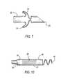
- FIG. 7is similar to a portion of FIG. 2 for an embodiment like that shown in FIG. 6 .
- FIG. 8is generally similar to FIG. 1 , but shows another illustrative embodiment of the invention.
- FIG. 8shows the tissue anchor portion of the apparatus in a deployed state.
- FIG. 9shows the undeployed state of the FIG. 8 embodiment.
- FIG. 10is similar to a portion of FIG. 1 , but shows another illustrative embodiment in accordance with the invention.
- FIG. 11is similar to a portion of FIG. 1 , but shows still another illustrative embodiment in accordance with the invention.
- FIG. 12is similar to a portion of FIG. 1 , but shows yet another illustrative embodiment in accordance with the invention.
- FIG. 13is similar to a portion of FIG. 1 , but shows still another illustrative embodiment in accordance with the invention.
- FIG. 14is similar to another portion of FIG. 1 , but shows another illustrative embodiment of the invention.
- FIG. 15shows another operating condition of what is shown in FIG. 14 in accordance with the invention.
- FIG. 16is a simplified longitudinal sectional view of a portion of yet another illustrative embodiment in accordance with the invention.
- FIGS. 17-21are each similar to a representative portion of FIG. 3 , 5 , or 6 , and show other examples of possible slot and intervening strip shapes in accordance with the invention.
- FIG. 22is a simplified elevational view of a structure of the type shown in FIG. 5 when deployed in accordance with the invention.
- FIG. 23is a simplified view taken along the line 23 - 23 in FIG. 22 .
- FIG. 24is a simplified isometric view of what is shown in FIGS. 22 and 23 .
- anchor structure 10(which is shown prior to deployment) includes elongated hollow structure or tubular member 20 , a longitudinal member 30 such as a wire disposed (for the most part) inside a lumen of member 20 , and a latch member 40 attached to the proximal end of member 30 .
- the distal end 22 of member 20may be shaped into a point or screw or other shape to facilitate tissue penetration, and/or the distal end of member 30 may accomplish the same.
- a relatively distal portion of member 20proximal of the extreme distal end of that member is shaped to include a number of spiral strips 24 (intercalated with spiral cuts 26 ).
- Strips 24 and cuts 26spiral in a circumferential direction around member 20 in the manner that relatively steep screw threads would spiral around a rod.
- FIG. 3shows a portion of member 20 cut longitudinally and laid flat to more clearly reveal the pattern of strips 24 and cuts 26 .
- the portion of member 20 proximal to strips 24is intact (i.e., not cut to produce spiral strips).
- strips 24are confined to a relatively distal portion of the length of member 20 , generally as shown in FIG. 1 .
- the distal end of member 30is secured to the distal portion 28 of member 20 (i.e., distal to strips 24 ).
- the distal end of member 30may be shaped such that motion relative to member 20 is limited to one-way motion, i.e., member 30 can move distally relative to member 20 , but it can only move proximally relative to portion 28 until it reaches a stop in portion 28 .
- the more proximal remainder of member 30is longitudinally or axially slidable along the length of member 20 , for the most part inside the lumen of member 20 .
- That memberhas a slot 50 in its side that is wide enough for member 30 to come out of that side of member 20 .
- the distal surface 42 of latch member 40is distal to the proximal or engagement surface 52 of member 20 .
- member 30is not long enough relative to the length of member 20 to permit latch member 40 to be located at the proximal end of member 20 .
- latch member 40 and a proximal portion of member 30are to one side of member 20 outside of slot 50 .
- the proximal portion of member 20is pushed distally relative to elements 30 and 40 .
- elements 30 and 40may be pulled proximally relative to the proximal portion of member 20 , or some combination of pushing and pulling may be employed.
- Thiscauses the distal portion 28 of member 20 (which is secured to the distal end of member 30 ) and the portion of member 20 that is proximal to strips 24 to move toward one another.
- Thiscauses strips 24 to buckle and deflect radially outwardly as shown in representative part in FIG. 2 and in a very simplified way in FIG. 4 .
- FIG. 2shows only two representative strips 24 to avoid complicating the drawing.
- FIG. 4shows a full set of strips 24 , but simplifies the representation of each strip to a single line, again to avoid over-complicating the drawing.
- latch member 40can be aligned with the proximal end of member 20 , as is also shown in FIG. 2 . In this position, latch member 40 holds strips 24 in their radially outward condition.
- latch member 40can be pushed off the proximal end of member 20 toward slot 50 . This allows the apparatus to return to the condition shown in FIG. 1 . In particular, it allows strips 24 to return to the condition in which they no longer project radially outwardly from the remainder of member 20 , but rather collectively form a structure that again has approximately the same outer circumferential size as the remainder of member 20 .
- apparatus 10An illustrative use of apparatus 10 is to penetrate tissue at a remote location and then provide an anchor in the tissue at that location.
- the distal tip 22 of member 20can be pushed into tissue at a remote location with the anchor structure 10 in the condition shown in FIG. 1 .
- the distal portion of the structureis pushed into the tissue until strips 24 (still undeployed as shown in FIG. 1 ) are below the surface of the tissue.
- strips 24can be deployed as shown in FIG. 2 to prevent the apparatus from being pulled out of the tissue.
- the apparatuscan be returned to the condition shown in FIG. 1 . In this condition the apparatus can be easily pulled out of the tissue.
- Another illustrative use of the apparatusis to push the undeployed anchor structure all the way through a tissue structure (e.g., the septum between two chambers of the heart).
- a tissue structuree.g., the septum between two chambers of the heart.
- the stripscan be deployed as shown in FIG. 2 to prevent the distal portion of the anchor structure from being pulled back into or through the tissue that has been passed through.
- strips 24can be undeployed (i.e., returned to the condition shown in FIG. 1 ) so that the structure can be easily pulled back through the tissue that it initially penetrated.
- Still another example of use of the apparatusis as a stop (which can be selectively activated or deactivated). For example, if it is desired to prevent member 20 from penetrating tissue by more than a certain distance, strips 24 can be deployed before or as penetration begins. Penetration stops when deployed strips 24 reach the surface of the tissue being penetrated. If further penetration is subsequently desired, strips 24 can be undeployed and penetration can be continued.
- Structure 10can be constructed with a wide range of different characteristics to satisfy many different needs.
- the stiffness of stripscan be varied widely by varying their width and thickness.
- the overall stiffness of the apparatuscan be varied by varying such parameters as the size and thickness of members 20 and 30 .
- Structure 10may be designed for delivery into the body inside a catheter and/or over a guide wire, and for that type of use may be made very thin and laterally flexible. Alternatively, structure 10 may be made bigger and laterally stiffer for other uses in which it needs to be more self-aligning.
- element 30may also be tubular so that apparatus 10 can be passed into the patient over the guide wire (i.e., with the guide wire passing along the lumen inside member 30 ).
- the size and strength of the anchor featurecan be varied. For example, stiffer strips 24 tend to provide a stronger anchor. Longer strips 24 can be used to provide a larger anchor (e.g., an anchor with a larger circumference when strips 24 are buckled and thereby deployed).
- Strips 24can be located at any distance from distal tip 22 to provide an anchor structure at any desired location along the apparatus.
- Spiral strips 24tend to be preferred because they tend to distribute the stress of buckling along more of the length of each strip, rather than producing stress concentrations at one or a few points along the length of each strip.
- the angle of inclination (the spiral angle) of the stripscan be different in different embodiments.
- structure 10may provide a guideway for introducing other apparatus into a patient.
- latch member 40when latch member 40 is latched at the proximal end of member 20 as shown in FIG. 2 , latch member 40 is effectively a proximal continuation of member 20 with the same outer cross-sectional size and shape as member 20 .
- Additional apparatuscan therefore be passed into the patient along structure 10 (e.g., concentrically around the outside of aligned members 20 and 40 ).
- Deployed anchor features 24hold the distal portion of structure 10 at the desired location in the patient's tissue. This can be used to help ensure that other apparatus introduced into the patient along structure 10 reaches the desired destination in the patient. It can also be used to help provide force (direct force or reaction force) needed by structure 10 and/or any other apparatus introduced into the patient via apparatus 10 in order to perform a procedure on the patient.
- Still another possible use of the apparatusis as a temporary or permanent electrical lead and connection to a patient's tissue, e.g., at the location of anchor features 24 .
- structure 10can be covered with electrical insulation except at strips 24 .
- Electrical currentcan be conducted to and/or from the patient at the location of deployed strips 24 via other metal components of the apparatus (e.g., member 20 ).
- An example of such electrical use of the apparatusis as an electrical lesion generator for ablation of a patient's tissue (e.g., at the location of anchor features 24 ).
- Cuts 26can be made in member 20 in any desired way. Laser cutting is an example. Cuts 26 can be shaped to affect the behavior of the apparatus in any of several ways. For example, FIG. 5 shows an embodiment in which cuts 26 are relatively wide slots, thereby increasing the spacing between strips 24 , making the strips narrower, etc. FIGS. 22-24 show several views of a FIG. 5 type anchor structure when deployed. As another example, FIG. 6 shows an embodiment in which cuts 26 are wider toward the left and narrower toward the right. This tends to make strips 24 weaker toward the left and stronger toward the right. A feature like this can be used to give the deployed anchor feature a particular shape. For example, FIG.
- FIG. 7shows that the deployed strips 24 cooperate to produce a cup-like anchor structure as a result of tapering cuts 26 as shown in FIG. 6 .
- Each stripis more resistant to curvature toward the right where it is stronger. This produces the left-ward opening, cup-like anchor structure shown in FIG. 7 . If slots 26 were tapered in the opposite direction from what is shown in FIG. 6 , the cup shape of FIG. 7 would face in the opposite direction.
- FIG. 17is similar to FIG. 6 , except that in FIG. 17 slots 26 are wider on the right than on the left. Thus in FIG. 17 strips 24 are wider on the left than on the right. This tends to produce a cup-like deployment of strips 24 as shown in FIG. 7 , except that the cup will be open from the right rather than from the left as in FIG. 7 .
- FIG. 18shows a slot and strip pattern similar to FIG. 6 . In FIG. 19 the width of slots 26 steps fairly abruptly from relatively narrow on the left to relatively wide on the right. This causes the width of intervening strips 24 to step correspondingly abruptly from relatively wide on the left to relatively narrow on the right. In FIG.
- each strip 24has a barb 25 that projects from one side of the strip into the adjacent slot 26 . Such barbs 25 can penetrate tissue when strips 24 are deployed. This can be used to increase the tissue holding and/or tissue penetrating power of the deployed anchor structure.
- FIGS. 8 and 9show another illustrative embodiment 10 ′ in which the unstressed condition of strips 24 is the radially outward, deployed condition as shown in FIG. 7 .
- latch member 40 ′is threaded onto the threaded end 50 ′ of member 20 .
- latch member 40 ′is rotatably secured to the proximal end of member 30 .
- FIGS. 8 and 9An illustrative way to provide embodiments of the type illustrated by FIGS. 8 and 9 is to make member 20 (or at least the relevant portion of member 20 ) from a nitinol tube, which has been heat-set in the condition shown in FIG. 8 .
- the deployed condition of strips 24thereby becomes the unstressed or at-rest condition of the apparatus. But the apparatus can be stressed to draw in strips 24 as shown in FIG. 9 when it is desired to undeploy the anchor feature.
- the distal end of member 20may include a tissue penetrating screw portion 60 as shown in FIG. 10 .
- member 20can be rotated to thread screw 60 into the tissue. In this way screw 60 effectively pulls the distal end of the apparatus into the tissue.
- FIG. 11shows an alternative embodiment in which anchor structure 10 is deployed inside a separate axially-slidable, tissue-piercing structure 100 .
- the distal end of structure 100is used to pierce or penetrate tissue.
- the distal end 102 of structure 100is sharpened for that purpose.
- anchor structure 10can be pushed out of the distal end of structure 100 as shown in FIG. 11 and tissue anchoring strips 24 can be deployed as shown, for example, in FIG. 2 . While strips 24 are thus deployed, structure 100 can be pulled off the proximal end of structure 10 and other apparatus for performing another part of a procedure can be exchanged for structure 100 (i.e., guided into the patient along and concentrically around structure 10 ).
- FIG. 12shows another alternative embodiment in which tissue penetrating structure 100 ′ leads with a tissue piercing or cutting screw portion 104 .
- the embodiment of FIG. 12may be similar to the embodiment of FIG. 11 .
- FIG. 13illustrates the point that structure 10 can be introduced into the patient along a guide wire 200 or the like.
- element 200 in FIG. 13may be a wire that is extended from the apparatus after there has been tissue penetration by element 20 .
- wire 200may be designed to meander after it has exited from structure 10 . This effectively gives the apparatus an atraumatic tip because meandering wire 200 prevents the distal end of structure 10 from being pushed farther than it is desired for it to be pushed.
- wire 200can become a guide wire for subsequent procedures (or, as has been mentioned, structure 10 can itself be a guide “wire” for subsequent procedures).
- a member that is inside of elements 20 and 30can be a tissue penetrating member, if desired. If that is done, then member 20 can follow the lead of the tissue penetrating member into the tissue, somewhat enlarging the tissue penetration as it goes.
- FIGS. 14 and 15show another illustrative embodiment of a latching structure 40 ′′.
- latching structure 40 ′′may be a tubular member that is similar in size to tubular member 20 .
- a distal portion of the length of member 40 ′′is cut axially so that some of that portion of member 40 ′′ can be resiliently opened to fit around the outside of the proximal end of member 20 as shown in FIG. 14 .
- member 40 ′′is pulled back proximally until its distal surface 42 ′′ closes down again and engages the proximal end 52 of member 20 as shown in FIG. 15 .
- member 40 ′′can spring part way closed to help surfaces 42 ′′ and 52 engage one another.
- member 40 ′′can be forced back over the proximal end of member 20 (i.e., back to the condition shown in FIG. 14 ).
- FIG. 16Another example of how the anchor structure of this invention can be constructed is shown in FIG. 16 (which, like several of the earlier FIGS., shows only the distal portion of anchor structure 10 ′′).
- an annular array of flexible members 24is attached at the distal end to inner member 30 , and it is attached at the proximal end to outer member 20 ′′.
- Flexible members 24can be deployed radially outwardly or pulled radially inwardly by relative axial motion of elements 20 ′′ and 30 .
- This type of constructionmay facilitate the fabrication of structure 24 separately from other elements, with the various parts being assembled later as shown in FIG. 16 .
- the component 23 that includes strips 24also includes an intact tubular portion at each end of the strips. In other words, strips 24 are confined to the intermediate portion of component 23 that is indicated by bracket or brace 23 ′.
- Examples of possible applications of the inventioninclude apparatus for use in crossing the septum of a patient's heart.
- vascular closureAnother example of a possible use is in vascular closure.
- the radially expandable, distal portion of the apparatusis inserted through the side wall of the vessel to be closed.
- the expandable portionis then expanded and pulled back slightly against the vessel wall.
- a clot-promoting agentmay be introduced outside the vessel wall.
- the radially expanded structurehelps to keep the clot-promoting agent from actually entering the vessel.
- the radially expandable structuremay be covered with a flexible membrane such as silicone to help keep the agent out of the vessel.
- the expandable structurecan be collapsed and withdrawn from the patient at the appropriate time.
- Still another example of possible use of the inventionis as an anchor in a body conduit such as a blood vessel.
- This usemay not involve tissue penetration. Rather, the expandable portion of the apparatus is expanded at a location in a vessel that is somewhat smaller in diameter than the apparatus when expanded. The expanded apparatus engages the side wall of the vessel and provides an anchor in the vessel.
- the apparatuscan be used as an anchor that is embedded in tissue.
- flexible members 24are preferably provided so that they spiral about a central longitudinal axis of the apparatus, they could be provided so that they are parallel to the central longitudinal axis (although this is not the presently preferred embodiment for reasons that are mentioned earlier).
- Flexible members 24preferably form a single layer of deflectable components. They are preferably not part of a multi-layered structure such as a braid of wires.
- the presently most preferred construction of the anchor structureis a single tube with intact end portions and an intermediate portion (between the end portions) that has been cut or slotted at several circumferentially spaced locations around the tube. The cuts or slots preferable spiral, but can be longitudinal of the tube in a presently less preferred embodiment.
- each of strips 24is integral (one piece) with an intact tube at each end of each strip.
- a presently less preferred constructionis to make each of strips 24 as a length of wire that extends between two axially aligned but spaced tubes.
- member 20may be made of a metal such as nitinol or stainless steel.
- Member 30may also be made of metal. Certain plastics may be suitable for all or portions of member 20 , including strips 24 .
- a medial portion of member 20(e.g., between the region of strips 24 and the region of slot 50 ) may be formed of a spiral-wound metal wire to increase lateral flexibility of the structure.
- member 30may be hollow if, for example, it is desired to pass a guide wire through the apparatus.
- the portion of the apparatus that includes strips 24may be made as a subassembly that is initially separate from other parts of the apparatus (including other portions of member 20 ).
- this part of member 20may be made separately from nitinol, and then attached to a remainder of member 20 that is made of stainless steel and/or of spiral wound wire.
- FIG. 16shows an example of an embodiment that can be constructed in this way.
- Strips 24may initially be separate members that are welded at their ends to tubes that form adjacent portions of member 20 .
Landscapes
- Health & Medical Sciences (AREA)
- Surgery (AREA)
- Life Sciences & Earth Sciences (AREA)
- Heart & Thoracic Surgery (AREA)
- Pathology (AREA)
- Oral & Maxillofacial Surgery (AREA)
- Engineering & Computer Science (AREA)
- Biomedical Technology (AREA)
- Nuclear Medicine, Radiotherapy & Molecular Imaging (AREA)
- Medical Informatics (AREA)
- Molecular Biology (AREA)
- Animal Behavior & Ethology (AREA)
- General Health & Medical Sciences (AREA)
- Public Health (AREA)
- Veterinary Medicine (AREA)
- Surgical Instruments (AREA)
Abstract
Description
Claims (12)
Priority Applications (4)
| Application Number | Priority Date | Filing Date | Title |
|---|---|---|---|
| US11/361,197US8882787B2 (en) | 2005-03-02 | 2006-02-23 | Tissue anchor apparatus |
| JP2007558136AJP2008531206A (en) | 2005-03-02 | 2006-02-28 | Tissue fixing device |
| EP06736421AEP1804679A1 (en) | 2005-03-02 | 2006-02-28 | Tissue anchor apparatus |
| PCT/US2006/007101WO2006093970A1 (en) | 2005-03-02 | 2006-02-28 | Tissue anchor apparatus |
Applications Claiming Priority (2)
| Application Number | Priority Date | Filing Date | Title |
|---|---|---|---|
| US65819405P | 2005-03-02 | 2005-03-02 | |
| US11/361,197US8882787B2 (en) | 2005-03-02 | 2006-02-23 | Tissue anchor apparatus |
Publications (2)
| Publication Number | Publication Date |
|---|---|
| US20060196137A1 US20060196137A1 (en) | 2006-09-07 |
| US8882787B2true US8882787B2 (en) | 2014-11-11 |
Family
ID=36534442
Family Applications (1)
| Application Number | Title | Priority Date | Filing Date |
|---|---|---|---|
| US11/361,197Expired - Fee RelatedUS8882787B2 (en) | 2005-03-02 | 2006-02-23 | Tissue anchor apparatus |
Country Status (4)
| Country | Link |
|---|---|
| US (1) | US8882787B2 (en) |
| EP (1) | EP1804679A1 (en) |
| JP (1) | JP2008531206A (en) |
| WO (1) | WO2006093970A1 (en) |
Cited By (5)
| Publication number | Priority date | Publication date | Assignee | Title |
|---|---|---|---|---|
| US20150216523A1 (en)* | 2014-02-05 | 2015-08-06 | James F. Marino | Anchor Devices and Methods of Use |
| US10398441B2 (en) | 2013-12-20 | 2019-09-03 | Terumo Corporation | Vascular occlusion |
| US11564692B2 (en) | 2018-11-01 | 2023-01-31 | Terumo Corporation | Occlusion systems |
| US12011174B2 (en) | 2020-04-28 | 2024-06-18 | Terumo Corporation | Occlusion systems |
| US12023035B2 (en) | 2017-05-25 | 2024-07-02 | Terumo Corporation | Adhesive occlusion systems |
Families Citing this family (41)
| Publication number | Priority date | Publication date | Assignee | Title |
|---|---|---|---|---|
| US7662161B2 (en) | 1999-09-13 | 2010-02-16 | Rex Medical, L.P | Vascular hole closure device |
| US9138228B2 (en) | 2004-08-11 | 2015-09-22 | Emory University | Vascular conduit device and system for implanting |
| WO2007059199A2 (en) | 2005-11-14 | 2007-05-24 | C.R. Bard, Inc. | Sling anchor system |
| US7815659B2 (en)* | 2005-11-15 | 2010-10-19 | Ethicon Endo-Surgery, Inc. | Suture anchor applicator |
| US7625392B2 (en)* | 2006-02-03 | 2009-12-01 | James Coleman | Wound closure devices and methods |
| WO2008033950A2 (en) | 2006-09-13 | 2008-03-20 | C. R. Bard, Inc. | Urethral support system |
| WO2008115922A1 (en) | 2007-03-19 | 2008-09-25 | Michael Brenzel | Methods and apparatus for occlusion of body lumens |
| US7846123B2 (en) | 2007-04-24 | 2010-12-07 | Emory University | Conduit device and system for implanting a conduit device in a tissue wall |
| US7976551B1 (en)* | 2007-06-14 | 2011-07-12 | Pacesetter, Inc. | Transseptal delivery instrument |
| EP2166954A1 (en) | 2007-07-13 | 2010-03-31 | Rex Medical, L.P. | Vascular hole closure device |
| US9301761B2 (en) | 2007-10-22 | 2016-04-05 | James E. Coleman | Anastomosis devices and methods |
| US8206280B2 (en) | 2007-11-13 | 2012-06-26 | C. R. Bard, Inc. | Adjustable tissue support member |
| US8920462B2 (en) | 2008-02-15 | 2014-12-30 | Rex Medical, L.P. | Vascular hole closure device |
| US8920463B2 (en) | 2008-02-15 | 2014-12-30 | Rex Medical, L.P. | Vascular hole closure device |
| US9226738B2 (en) | 2008-02-15 | 2016-01-05 | Rex Medical, L.P. | Vascular hole closure delivery device |
| US8491629B2 (en) | 2008-02-15 | 2013-07-23 | Rex Medical | Vascular hole closure delivery device |
| US8070772B2 (en) | 2008-02-15 | 2011-12-06 | Rex Medical, L.P. | Vascular hole closure device |
| US20110029013A1 (en) | 2008-02-15 | 2011-02-03 | Mcguckin James F | Vascular Hole Closure Device |
| AU2009256738C1 (en)* | 2008-06-10 | 2013-08-01 | Bavaria Medizin Technologie Gmbh | Scoring catheter for treating diseased heart valves |
| US8197498B2 (en)* | 2008-11-06 | 2012-06-12 | Trinitas Ventures Ltd. | Gastric bypass devices and procedures |
| WO2011025528A1 (en)* | 2009-08-31 | 2011-03-03 | St. Jude Medical Puerto Rico Llc | Compressible arteriotomy locator for vascular closure devices and methods |
| JP6130302B2 (en) | 2011-01-28 | 2017-05-17 | アピカ カーディオヴァスキュラー リミテッド | System for sealing tissue wall stings |
| WO2012106422A2 (en) | 2011-02-01 | 2012-08-09 | Georgia Tech Research Corporation | Systems for implanting and using a conduit within a tissue wall |
| AU2012202202B2 (en)* | 2011-07-20 | 2017-05-11 | Rex Medical, L.P. | Vascular hole closure delivery device |
| US9247930B2 (en) | 2011-12-21 | 2016-02-02 | James E. Coleman | Devices and methods for occluding or promoting fluid flow |
| EP2948104B1 (en) | 2013-01-25 | 2019-07-24 | Apica Cardiovascular Limited | Systems for percutaneous access, stabilization and closure of organs |
| US9698062B2 (en)* | 2013-02-28 | 2017-07-04 | Veeco Precision Surface Processing Llc | System and method for performing a wet etching process |
| EP2968717A4 (en) | 2013-03-15 | 2017-02-22 | Apk Advanced Medical Technologies, Inc. | Devices, systems, and methods for implanting and using a connnector in a tissue wall |
| US20140305530A1 (en)* | 2013-04-14 | 2014-10-16 | Calore Medical Ltd. | Expanding medical device formed of slotted metal tube |
| US20140371786A1 (en)* | 2013-04-14 | 2014-12-18 | Calore Medical Ltd. | Expandable medical anchor device formed of cut metal tube |
| US9839416B2 (en) | 2013-07-12 | 2017-12-12 | Phillips Medical, LLC | Hemostatic device and its methods of use |
| US10085730B2 (en) | 2013-07-12 | 2018-10-02 | Phillips Medical, LLC | Hemostatic device and its methods of use |
| WO2015059567A2 (en)* | 2013-10-23 | 2015-04-30 | Calore Medical Ltd. | Expandable medical anchor device formed of cut metal tube |
| WO2016024235A1 (en)* | 2014-08-12 | 2016-02-18 | Medivalve Ltd. | Multi-stage imaging aid (mia) |
| US10485909B2 (en) | 2014-10-31 | 2019-11-26 | Thoratec Corporation | Apical connectors and instruments for use in a heart wall |
| AU2016215197B2 (en) | 2015-02-05 | 2020-01-02 | Tendyne Holdings Inc. | Expandable epicardial pads and devices and methods for their delivery |
| EP3294146A1 (en)* | 2015-05-11 | 2018-03-21 | Phillips Medical, LLC | Hemostatic device and its methods of use |
| JP7394049B2 (en) | 2017-03-22 | 2023-12-07 | ユニバーシティー オブ メリーランド,ボルティモア | Devices and methods for transseptal puncture |
| US11045224B2 (en) | 2018-09-24 | 2021-06-29 | University Of Maryland, Baltimore | Apparatus and method for septal punch |
| US11504105B2 (en) | 2019-01-25 | 2022-11-22 | Rex Medical L.P. | Vascular hole closure device |
| EP4199860A1 (en) | 2020-08-19 | 2023-06-28 | Tendyne Holdings, Inc. | Fully-transseptal apical pad with pulley for tensioning |
Citations (29)
| Publication number | Priority date | Publication date | Assignee | Title |
|---|---|---|---|---|
| US4274324A (en)* | 1978-04-18 | 1981-06-23 | Giannuzzi Louis | Hollow wall screw anchor |
| US5257975A (en)* | 1992-08-14 | 1993-11-02 | Edward Weck Incorporated | Cannula retention device |
| US5456667A (en)* | 1993-05-20 | 1995-10-10 | Advanced Cardiovascular Systems, Inc. | Temporary stenting catheter with one-piece expandable segment |
| US5501695A (en)* | 1992-05-27 | 1996-03-26 | The Anspach Effort, Inc. | Fastener for attaching objects to bones |
| WO1998047430A1 (en) | 1997-04-23 | 1998-10-29 | Vascular Science Inc. | Medical plug |
| US5853422A (en)* | 1996-03-22 | 1998-12-29 | Scimed Life Systems, Inc. | Apparatus and method for closing a septal defect |
| US6022373A (en)* | 1996-09-10 | 2000-02-08 | Li Medical Technologies, Inc. | Surgical anchor and package and cartridge for surgical anchor |
| US6074416A (en) | 1997-10-09 | 2000-06-13 | St. Jude Medical Cardiovascular Group, Inc. | Wire connector structures for tubular grafts |
| US6113609A (en)* | 1998-05-26 | 2000-09-05 | Scimed Life Systems, Inc. | Implantable tissue fastener and system for treating gastroesophageal reflux disease |
| US6171319B1 (en)* | 1997-05-19 | 2001-01-09 | Cardio Medical Solutions, Inc. | Anastomosis device with hole punch |
| US6231561B1 (en)* | 1999-09-20 | 2001-05-15 | Appriva Medical, Inc. | Method and apparatus for closing a body lumen |
| US20010041858A1 (en) | 1998-01-23 | 2001-11-15 | Pinaki Ray | Methods and devices for occluding the ascending aorta and maintaining circulation of oxygenated blood in the patient when the patient's heart is arrested |
| US20010047187A1 (en) | 1998-11-06 | 2001-11-29 | Neomend, Inc. | Systems, methods, and compositions for achieving closure of vascular puncture sites |
| US6328758B1 (en)* | 1998-04-21 | 2001-12-11 | Tornier Sa | Suture anchor with reversible expansion |
| US20020042628A1 (en) | 1997-07-10 | 2002-04-11 | Yem Chin | Removable occlusion system for aneurysm neck |
| US20020072768A1 (en)* | 2000-12-07 | 2002-06-13 | Ginn Richard S. | Apparatus and methods for providing tactile feedback while delivering a closure device |
| US6461320B1 (en)* | 1998-08-12 | 2002-10-08 | Cardica, Inc. | Method and system for attaching a graft to a blood vessel |
| US20030078616A1 (en) | 2000-12-14 | 2003-04-24 | Core Medical, Inc. | Plug with detachable guidewire element and methods for use |
| US6660008B1 (en)* | 2001-06-07 | 2003-12-09 | Opus Medical, Inc. | Method and apparatus for attaching connective tissues to bone using a suture anchoring device |
| US20030236536A1 (en)* | 2002-06-20 | 2003-12-25 | Scimed Life Systems, Inc. | Endoscopic fundoplication devices and methods for treatment of gastroesophageal reflux disease |
| US20050043759A1 (en)* | 2003-07-14 | 2005-02-24 | Nmt Medical, Inc. | Tubular patent foramen ovale (PFO) closure device with catch system |
| US20050075665A1 (en) | 2003-09-19 | 2005-04-07 | St. Jude Medical, Inc. | Apparatus and methods for tissue gathering and securing |
| US6893418B2 (en)* | 2000-01-07 | 2005-05-17 | Boston Scientific Scimed, Inc. | Drainage catheter with dilating member |
| US20050119675A1 (en)* | 2003-10-24 | 2005-06-02 | Adams Daniel O. | Patent foramen ovale closure system |
| US20050273135A1 (en)* | 2004-05-07 | 2005-12-08 | Nmt Medical, Inc. | Catching mechanisms for tubular septal occluder |
| US20060122647A1 (en)* | 2004-09-24 | 2006-06-08 | Callaghan David J | Occluder device double securement system for delivery/recovery of such occluder device |
| US7097653B2 (en) | 2000-01-04 | 2006-08-29 | Pfm Produkte Fur Die Medizin Aktiengesellschaft | Implant for the closing of defect openings in the body of a human or animal and a system for the placement of such an implant |
| US7149587B2 (en)* | 2002-09-26 | 2006-12-12 | Pacesetter, Inc. | Cardiovascular anchoring device and method of deploying same |
| US7713282B2 (en)* | 1998-11-06 | 2010-05-11 | Atritech, Inc. | Detachable atrial appendage occlusion balloon |
Family Cites Families (1)
| Publication number | Priority date | Publication date | Assignee | Title |
|---|---|---|---|---|
| US7569066B2 (en)* | 1997-07-10 | 2009-08-04 | Boston Scientific Scimed, Inc. | Methods and devices for the treatment of aneurysms |
- 2006
- 2006-02-23USUS11/361,197patent/US8882787B2/ennot_activeExpired - Fee Related
- 2006-02-28JPJP2007558136Apatent/JP2008531206A/enactivePending
- 2006-02-28WOPCT/US2006/007101patent/WO2006093970A1/enactiveApplication Filing
- 2006-02-28EPEP06736421Apatent/EP1804679A1/ennot_activeWithdrawn
Patent Citations (30)
| Publication number | Priority date | Publication date | Assignee | Title |
|---|---|---|---|---|
| US4274324A (en)* | 1978-04-18 | 1981-06-23 | Giannuzzi Louis | Hollow wall screw anchor |
| US5501695A (en)* | 1992-05-27 | 1996-03-26 | The Anspach Effort, Inc. | Fastener for attaching objects to bones |
| US5257975A (en)* | 1992-08-14 | 1993-11-02 | Edward Weck Incorporated | Cannula retention device |
| US5456667A (en)* | 1993-05-20 | 1995-10-10 | Advanced Cardiovascular Systems, Inc. | Temporary stenting catheter with one-piece expandable segment |
| US5853422A (en)* | 1996-03-22 | 1998-12-29 | Scimed Life Systems, Inc. | Apparatus and method for closing a septal defect |
| US6022373A (en)* | 1996-09-10 | 2000-02-08 | Li Medical Technologies, Inc. | Surgical anchor and package and cartridge for surgical anchor |
| WO1998047430A1 (en) | 1997-04-23 | 1998-10-29 | Vascular Science Inc. | Medical plug |
| US6171319B1 (en)* | 1997-05-19 | 2001-01-09 | Cardio Medical Solutions, Inc. | Anastomosis device with hole punch |
| US20020042628A1 (en) | 1997-07-10 | 2002-04-11 | Yem Chin | Removable occlusion system for aneurysm neck |
| US6074416A (en) | 1997-10-09 | 2000-06-13 | St. Jude Medical Cardiovascular Group, Inc. | Wire connector structures for tubular grafts |
| US20010041858A1 (en) | 1998-01-23 | 2001-11-15 | Pinaki Ray | Methods and devices for occluding the ascending aorta and maintaining circulation of oxygenated blood in the patient when the patient's heart is arrested |
| US6328758B1 (en)* | 1998-04-21 | 2001-12-11 | Tornier Sa | Suture anchor with reversible expansion |
| US6113609A (en)* | 1998-05-26 | 2000-09-05 | Scimed Life Systems, Inc. | Implantable tissue fastener and system for treating gastroesophageal reflux disease |
| US6461320B1 (en)* | 1998-08-12 | 2002-10-08 | Cardica, Inc. | Method and system for attaching a graft to a blood vessel |
| US20010047187A1 (en) | 1998-11-06 | 2001-11-29 | Neomend, Inc. | Systems, methods, and compositions for achieving closure of vascular puncture sites |
| US7713282B2 (en)* | 1998-11-06 | 2010-05-11 | Atritech, Inc. | Detachable atrial appendage occlusion balloon |
| US6231561B1 (en)* | 1999-09-20 | 2001-05-15 | Appriva Medical, Inc. | Method and apparatus for closing a body lumen |
| US7097653B2 (en) | 2000-01-04 | 2006-08-29 | Pfm Produkte Fur Die Medizin Aktiengesellschaft | Implant for the closing of defect openings in the body of a human or animal and a system for the placement of such an implant |
| US6893418B2 (en)* | 2000-01-07 | 2005-05-17 | Boston Scientific Scimed, Inc. | Drainage catheter with dilating member |
| US20020072768A1 (en)* | 2000-12-07 | 2002-06-13 | Ginn Richard S. | Apparatus and methods for providing tactile feedback while delivering a closure device |
| US20030078616A1 (en) | 2000-12-14 | 2003-04-24 | Core Medical, Inc. | Plug with detachable guidewire element and methods for use |
| US6660008B1 (en)* | 2001-06-07 | 2003-12-09 | Opus Medical, Inc. | Method and apparatus for attaching connective tissues to bone using a suture anchoring device |
| US20030236536A1 (en)* | 2002-06-20 | 2003-12-25 | Scimed Life Systems, Inc. | Endoscopic fundoplication devices and methods for treatment of gastroesophageal reflux disease |
| US7149587B2 (en)* | 2002-09-26 | 2006-12-12 | Pacesetter, Inc. | Cardiovascular anchoring device and method of deploying same |
| US20050043759A1 (en)* | 2003-07-14 | 2005-02-24 | Nmt Medical, Inc. | Tubular patent foramen ovale (PFO) closure device with catch system |
| US20050075665A1 (en) | 2003-09-19 | 2005-04-07 | St. Jude Medical, Inc. | Apparatus and methods for tissue gathering and securing |
| US20050119675A1 (en)* | 2003-10-24 | 2005-06-02 | Adams Daniel O. | Patent foramen ovale closure system |
| US20050273135A1 (en)* | 2004-05-07 | 2005-12-08 | Nmt Medical, Inc. | Catching mechanisms for tubular septal occluder |
| US8257389B2 (en)* | 2004-05-07 | 2012-09-04 | W.L. Gore & Associates, Inc. | Catching mechanisms for tubular septal occluder |
| US20060122647A1 (en)* | 2004-09-24 | 2006-06-08 | Callaghan David J | Occluder device double securement system for delivery/recovery of such occluder device |
Cited By (8)
| Publication number | Priority date | Publication date | Assignee | Title |
|---|---|---|---|---|
| US10398441B2 (en) | 2013-12-20 | 2019-09-03 | Terumo Corporation | Vascular occlusion |
| US11832824B2 (en) | 2013-12-20 | 2023-12-05 | Terumo Corporation | Vascular occlusion |
| US20150216523A1 (en)* | 2014-02-05 | 2015-08-06 | James F. Marino | Anchor Devices and Methods of Use |
| US9980715B2 (en)* | 2014-02-05 | 2018-05-29 | Trinity Orthopedics, Llc | Anchor devices and methods of use |
| US12023035B2 (en) | 2017-05-25 | 2024-07-02 | Terumo Corporation | Adhesive occlusion systems |
| US11564692B2 (en) | 2018-11-01 | 2023-01-31 | Terumo Corporation | Occlusion systems |
| US12290266B2 (en) | 2018-11-01 | 2025-05-06 | Terumo Corporation | Occlusion systems |
| US12011174B2 (en) | 2020-04-28 | 2024-06-18 | Terumo Corporation | Occlusion systems |
Also Published As
| Publication number | Publication date |
|---|---|
| JP2008531206A (en) | 2008-08-14 |
| WO2006093970A1 (en) | 2006-09-08 |
| US20060196137A1 (en) | 2006-09-07 |
| EP1804679A1 (en) | 2007-07-11 |
Similar Documents
| Publication | Publication Date | Title |
|---|---|---|
| US8882787B2 (en) | Tissue anchor apparatus | |
| US12096929B2 (en) | Flexible anchor delivery system | |
| JP4767292B2 (en) | Device for use in closing a septal defect | |
| US7842049B2 (en) | Systems for anchoring a medical device in a body lumen | |
| US20080082083A1 (en) | Perforated expandable implant recovery sheath | |
| JP4879744B2 (en) | System to improve heart function | |
| US7963952B2 (en) | Expandable sheath tubing | |
| US9173652B2 (en) | All-suture anchor inserter | |
| US7747333B2 (en) | Lead assembly and methods including a push tube | |
| US6132438A (en) | Devices for installing stasis reducing means in body tissue | |
| EP1807010B1 (en) | Remote body tissue engaging apparatus | |
| US9339265B2 (en) | Medical devices, systems, and methods for using tissue anchors | |
| US20110178537A1 (en) | Tissue repair implant and delivery device and method | |
| JP2002263111A (en) | Sampling tool for endoscope | |
| US20100105981A1 (en) | Puncturing Instrument | |
| CN110072474A (en) | The equipment and associated insertion type medical system in channel are formed in the tissue | |
| US11918205B2 (en) | Self locking suture and self locking suture mediated closure device | |
| KR20190101452A (en) | Endoscope Ultrasonic Inductive Access Device | |
| JP2017536943A (en) | Two-part anchor with anchor inserter | |
| US20250295406A1 (en) | Tissue-piercing implant | |
| US20230293184A1 (en) | Interference feature for inhibiting premature embolic implant detachment | |
| CN111148477A (en) | Tissue anchor with hemostatic features | |
| CN120585388A (en) | Automatic biopsy device and biopsy system that triggers | |
| KR20250112846A (en) | Barbed suture with removable sheath |
Legal Events
| Date | Code | Title | Description |
|---|---|---|---|
| AS | Assignment | Owner name:ST. JUDE MEDICAL, INC., MINNESOTA Free format text:ASSIGNMENT OF ASSIGNORS INTEREST;ASSIGNORS:BRENZEL, MICHAEL P.;DALE, THEODORE P.;COSTELLO, DAVID M.;AND OTHERS;SIGNING DATES FROM 20060209 TO 20060217;REEL/FRAME:017616/0766 Owner name:ST. JUDE MEDICAL, INC., MINNESOTA Free format text:ASSIGNMENT OF ASSIGNORS INTEREST;ASSIGNORS:BRENZEL, MICHAEL P.;DALE, THEODORE P.;COSTELLO, DAVID M.;AND OTHERS;REEL/FRAME:017616/0766;SIGNING DATES FROM 20060209 TO 20060217 | |
| STCF | Information on status: patent grant | Free format text:PATENTED CASE | |
| AS | Assignment | Owner name:ST. JUDE MEDICAL, LLC, ILLINOIS Free format text:MERGER AND CHANGE OF NAME;ASSIGNORS:ST. JUDE MEDICAL, INC.;VAULT MERGER SUB, LLC;REEL/FRAME:044583/0906 Effective date:20170104 | |
| MAFP | Maintenance fee payment | Free format text:PAYMENT OF MAINTENANCE FEE, 4TH YEAR, LARGE ENTITY (ORIGINAL EVENT CODE: M1551) Year of fee payment:4 | |
| FEPP | Fee payment procedure | Free format text:MAINTENANCE FEE REMINDER MAILED (ORIGINAL EVENT CODE: REM.); ENTITY STATUS OF PATENT OWNER: LARGE ENTITY | |
| LAPS | Lapse for failure to pay maintenance fees | Free format text:PATENT EXPIRED FOR FAILURE TO PAY MAINTENANCE FEES (ORIGINAL EVENT CODE: EXP.); ENTITY STATUS OF PATENT OWNER: LARGE ENTITY | |
| STCH | Information on status: patent discontinuation | Free format text:PATENT EXPIRED DUE TO NONPAYMENT OF MAINTENANCE FEES UNDER 37 CFR 1.362 | |
| FP | Lapsed due to failure to pay maintenance fee | Effective date:20221111 |