US8882774B2 - Instrumentation for the preparation and transplantation of osteochondral allografts - Google Patents
Instrumentation for the preparation and transplantation of osteochondral allograftsDownload PDFInfo
- Publication number
- US8882774B2 US8882774B2US11/677,414US67741407AUS8882774B2US 8882774 B2US8882774 B2US 8882774B2US 67741407 AUS67741407 AUS 67741407AUS 8882774 B2US8882774 B2US 8882774B2
- Authority
- US
- United States
- Prior art keywords
- handle
- drill bit
- teeth
- guide pin
- burr
- Prior art date
- Legal status (The legal status is an assumption and is not a legal conclusion. Google has not performed a legal analysis and makes no representation as to the accuracy of the status listed.)
- Active, expires
Links
- 238000002054transplantationMethods0.000titledescription4
- 210000000988bone and boneAnatomy0.000claimsabstractdescription110
- 230000007246mechanismEffects0.000claimsdescription7
- 210000000845cartilageAnatomy0.000abstractdescription60
- 238000000034methodMethods0.000abstractdescription18
- 206010061762ChondropathyDiseases0.000abstractdescription2
- 230000008439repair processEffects0.000abstractdescription2
- 230000000717retained effectEffects0.000abstractdescription2
- 230000007547defectEffects0.000description15
- 239000000463materialSubstances0.000description12
- 210000001519tissueAnatomy0.000description11
- 238000007493shaping processMethods0.000description10
- 230000008901benefitEffects0.000description7
- 238000003780insertionMethods0.000description4
- 230000037431insertionEffects0.000description4
- 229920001971elastomerPolymers0.000description3
- 239000000806elastomerSubstances0.000description3
- 208000014674injuryDiseases0.000description3
- 230000002411adverseEffects0.000description2
- 230000000890antigenic effectEffects0.000description2
- 230000006378damageEffects0.000description2
- 230000008569processEffects0.000description2
- 230000009467reductionEffects0.000description2
- 230000008733traumaEffects0.000description2
- 239000011800void materialSubstances0.000description2
- 206010067484Adverse reactionDiseases0.000description1
- 241001465754MetazoaSpecies0.000description1
- 208000027418Wounds and injuryDiseases0.000description1
- 230000006838adverse reactionEffects0.000description1
- 238000004873anchoringMethods0.000description1
- 210000003811fingerAnatomy0.000description1
- -1for exampleSubstances0.000description1
- 230000006870functionEffects0.000description1
- 230000035876healingEffects0.000description1
- 238000002513implantationMethods0.000description1
- 238000010348incorporationMethods0.000description1
- 238000009434installationMethods0.000description1
- 210000000629knee jointAnatomy0.000description1
- 238000005461lubricationMethods0.000description1
- 238000012986modificationMethods0.000description1
- 230000004048modificationEffects0.000description1
- 230000000750progressive effectEffects0.000description1
- 230000002035prolonged effectEffects0.000description1
- 230000001902propagating effectEffects0.000description1
- 238000002407reformingMethods0.000description1
- 230000004044responseEffects0.000description1
- 229920002379silicone rubberPolymers0.000description1
- 239000004945silicone rubberSubstances0.000description1
- 239000007779soft materialSubstances0.000description1
- 229910001220stainless steelInorganic materials0.000description1
- 239000010935stainless steelSubstances0.000description1
- 210000005065subchondral bone plateAnatomy0.000description1
- 210000003813thumbAnatomy0.000description1
Images


Classifications
- A—HUMAN NECESSITIES
- A61—MEDICAL OR VETERINARY SCIENCE; HYGIENE
- A61B—DIAGNOSIS; SURGERY; IDENTIFICATION
- A61B17/00—Surgical instruments, devices or methods
- A61B17/16—Instruments for performing osteoclasis; Drills or chisels for bones; Trepans
- A61B17/1613—Component parts
- A61B17/1615—Drill bits, i.e. rotating tools extending from a handpiece to contact the worked material
- A—HUMAN NECESSITIES
- A61—MEDICAL OR VETERINARY SCIENCE; HYGIENE
- A61B—DIAGNOSIS; SURGERY; IDENTIFICATION
- A61B17/00—Surgical instruments, devices or methods
- A61B17/16—Instruments for performing osteoclasis; Drills or chisels for bones; Trepans
- A61B17/1604—Chisels; Rongeurs; Punches; Stamps
- A—HUMAN NECESSITIES
- A61—MEDICAL OR VETERINARY SCIENCE; HYGIENE
- A61F—FILTERS IMPLANTABLE INTO BLOOD VESSELS; PROSTHESES; DEVICES PROVIDING PATENCY TO, OR PREVENTING COLLAPSING OF, TUBULAR STRUCTURES OF THE BODY, e.g. STENTS; ORTHOPAEDIC, NURSING OR CONTRACEPTIVE DEVICES; FOMENTATION; TREATMENT OR PROTECTION OF EYES OR EARS; BANDAGES, DRESSINGS OR ABSORBENT PADS; FIRST-AID KITS
- A61F2/00—Filters implantable into blood vessels; Prostheses, i.e. artificial substitutes or replacements for parts of the body; Appliances for connecting them with the body; Devices providing patency to, or preventing collapsing of, tubular structures of the body, e.g. stents
- A61F2/02—Prostheses implantable into the body
- A61F2/28—Bones
- A—HUMAN NECESSITIES
- A61—MEDICAL OR VETERINARY SCIENCE; HYGIENE
- A61F—FILTERS IMPLANTABLE INTO BLOOD VESSELS; PROSTHESES; DEVICES PROVIDING PATENCY TO, OR PREVENTING COLLAPSING OF, TUBULAR STRUCTURES OF THE BODY, e.g. STENTS; ORTHOPAEDIC, NURSING OR CONTRACEPTIVE DEVICES; FOMENTATION; TREATMENT OR PROTECTION OF EYES OR EARS; BANDAGES, DRESSINGS OR ABSORBENT PADS; FIRST-AID KITS
- A61F2/00—Filters implantable into blood vessels; Prostheses, i.e. artificial substitutes or replacements for parts of the body; Appliances for connecting them with the body; Devices providing patency to, or preventing collapsing of, tubular structures of the body, e.g. stents
- A61F2/02—Prostheses implantable into the body
- A61F2/30—Joints
- A61F2/30756—Cartilage endoprostheses
- A—HUMAN NECESSITIES
- A61—MEDICAL OR VETERINARY SCIENCE; HYGIENE
- A61F—FILTERS IMPLANTABLE INTO BLOOD VESSELS; PROSTHESES; DEVICES PROVIDING PATENCY TO, OR PREVENTING COLLAPSING OF, TUBULAR STRUCTURES OF THE BODY, e.g. STENTS; ORTHOPAEDIC, NURSING OR CONTRACEPTIVE DEVICES; FOMENTATION; TREATMENT OR PROTECTION OF EYES OR EARS; BANDAGES, DRESSINGS OR ABSORBENT PADS; FIRST-AID KITS
- A61F2/00—Filters implantable into blood vessels; Prostheses, i.e. artificial substitutes or replacements for parts of the body; Appliances for connecting them with the body; Devices providing patency to, or preventing collapsing of, tubular structures of the body, e.g. stents
- A61F2/02—Prostheses implantable into the body
- A61F2/30—Joints
- A61F2/46—Special tools for implanting artificial joints
- A61F2/4644—Preparation of bone graft, bone plugs or bone dowels, e.g. grinding or milling bone material
- A—HUMAN NECESSITIES
- A61—MEDICAL OR VETERINARY SCIENCE; HYGIENE
- A61B—DIAGNOSIS; SURGERY; IDENTIFICATION
- A61B17/00—Surgical instruments, devices or methods
- A61B17/04—Surgical instruments, devices or methods for suturing wounds; Holders or packages for needles or suture materials
- A61B17/06—Needles ; Sutures; Needle-suture combinations; Holders or packages for needles or suture materials
- A61B17/06166—Sutures
- A—HUMAN NECESSITIES
- A61—MEDICAL OR VETERINARY SCIENCE; HYGIENE
- A61B—DIAGNOSIS; SURGERY; IDENTIFICATION
- A61B17/00—Surgical instruments, devices or methods
- A61B17/16—Instruments for performing osteoclasis; Drills or chisels for bones; Trepans
- A61B17/1662—Instruments for performing osteoclasis; Drills or chisels for bones; Trepans for particular parts of the body
- A61B17/1675—Instruments for performing osteoclasis; Drills or chisels for bones; Trepans for particular parts of the body for the knee
- A—HUMAN NECESSITIES
- A61—MEDICAL OR VETERINARY SCIENCE; HYGIENE
- A61B—DIAGNOSIS; SURGERY; IDENTIFICATION
- A61B17/00—Surgical instruments, devices or methods
- A61B17/28—Surgical forceps
- A61B17/2812—Surgical forceps with a single pivotal connection
- A61B17/282—Jaws
- A—HUMAN NECESSITIES
- A61—MEDICAL OR VETERINARY SCIENCE; HYGIENE
- A61B—DIAGNOSIS; SURGERY; IDENTIFICATION
- A61B17/00—Surgical instruments, devices or methods
- A61B17/28—Surgical forceps
- A61B17/2812—Surgical forceps with a single pivotal connection
- A61B17/2833—Locking means
- A61B2017/2837—Locking means with a locking ratchet
- A—HUMAN NECESSITIES
- A61—MEDICAL OR VETERINARY SCIENCE; HYGIENE
- A61B—DIAGNOSIS; SURGERY; IDENTIFICATION
- A61B17/00—Surgical instruments, devices or methods
- A61B17/56—Surgical instruments or methods for treatment of bones or joints; Devices specially adapted therefor
- A61B17/58—Surgical instruments or methods for treatment of bones or joints; Devices specially adapted therefor for osteosynthesis, e.g. bone plates, screws or setting implements
- A61B17/88—Osteosynthesis instruments; Methods or means for implanting or extracting internal or external fixation devices
- A61B17/92—Impactors or extractors, e.g. for removing intramedullary devices
- A61B2017/922—Devices for impaction, impact element
- A—HUMAN NECESSITIES
- A61—MEDICAL OR VETERINARY SCIENCE; HYGIENE
- A61F—FILTERS IMPLANTABLE INTO BLOOD VESSELS; PROSTHESES; DEVICES PROVIDING PATENCY TO, OR PREVENTING COLLAPSING OF, TUBULAR STRUCTURES OF THE BODY, e.g. STENTS; ORTHOPAEDIC, NURSING OR CONTRACEPTIVE DEVICES; FOMENTATION; TREATMENT OR PROTECTION OF EYES OR EARS; BANDAGES, DRESSINGS OR ABSORBENT PADS; FIRST-AID KITS
- A61F2/00—Filters implantable into blood vessels; Prostheses, i.e. artificial substitutes or replacements for parts of the body; Appliances for connecting them with the body; Devices providing patency to, or preventing collapsing of, tubular structures of the body, e.g. stents
- A61F2/02—Prostheses implantable into the body
- A61F2/30—Joints
- A61F2/38—Joints for elbows or knees
- A61F2/3859—Femoral components
- A—HUMAN NECESSITIES
- A61—MEDICAL OR VETERINARY SCIENCE; HYGIENE
- A61F—FILTERS IMPLANTABLE INTO BLOOD VESSELS; PROSTHESES; DEVICES PROVIDING PATENCY TO, OR PREVENTING COLLAPSING OF, TUBULAR STRUCTURES OF THE BODY, e.g. STENTS; ORTHOPAEDIC, NURSING OR CONTRACEPTIVE DEVICES; FOMENTATION; TREATMENT OR PROTECTION OF EYES OR EARS; BANDAGES, DRESSINGS OR ABSORBENT PADS; FIRST-AID KITS
- A61F2/00—Filters implantable into blood vessels; Prostheses, i.e. artificial substitutes or replacements for parts of the body; Appliances for connecting them with the body; Devices providing patency to, or preventing collapsing of, tubular structures of the body, e.g. stents
- A61F2/02—Prostheses implantable into the body
- A61F2/30—Joints
- A61F2/46—Special tools for implanting artificial joints
- A61F2/4601—Special tools for implanting artificial joints for introducing bone substitute, for implanting bone graft implants or for compacting them in the bone cavity
- A—HUMAN NECESSITIES
- A61—MEDICAL OR VETERINARY SCIENCE; HYGIENE
- A61F—FILTERS IMPLANTABLE INTO BLOOD VESSELS; PROSTHESES; DEVICES PROVIDING PATENCY TO, OR PREVENTING COLLAPSING OF, TUBULAR STRUCTURES OF THE BODY, e.g. STENTS; ORTHOPAEDIC, NURSING OR CONTRACEPTIVE DEVICES; FOMENTATION; TREATMENT OR PROTECTION OF EYES OR EARS; BANDAGES, DRESSINGS OR ABSORBENT PADS; FIRST-AID KITS
- A61F2/00—Filters implantable into blood vessels; Prostheses, i.e. artificial substitutes or replacements for parts of the body; Appliances for connecting them with the body; Devices providing patency to, or preventing collapsing of, tubular structures of the body, e.g. stents
- A61F2/02—Prostheses implantable into the body
- A61F2/30—Joints
- A61F2/46—Special tools for implanting artificial joints
- A61F2/4603—Special tools for implanting artificial joints for insertion or extraction of endoprosthetic joints or of accessories thereof
- A61F2/4618—Special tools for implanting artificial joints for insertion or extraction of endoprosthetic joints or of accessories thereof of cartilage
- A—HUMAN NECESSITIES
- A61—MEDICAL OR VETERINARY SCIENCE; HYGIENE
- A61F—FILTERS IMPLANTABLE INTO BLOOD VESSELS; PROSTHESES; DEVICES PROVIDING PATENCY TO, OR PREVENTING COLLAPSING OF, TUBULAR STRUCTURES OF THE BODY, e.g. STENTS; ORTHOPAEDIC, NURSING OR CONTRACEPTIVE DEVICES; FOMENTATION; TREATMENT OR PROTECTION OF EYES OR EARS; BANDAGES, DRESSINGS OR ABSORBENT PADS; FIRST-AID KITS
- A61F2/00—Filters implantable into blood vessels; Prostheses, i.e. artificial substitutes or replacements for parts of the body; Appliances for connecting them with the body; Devices providing patency to, or preventing collapsing of, tubular structures of the body, e.g. stents
- A61F2/02—Prostheses implantable into the body
- A61F2/28—Bones
- A61F2002/2835—Bone graft implants for filling a bony defect or an endoprosthesis cavity, e.g. by synthetic material or biological material
- A61F2002/2839—Bone plugs or bone graft dowels
- A—HUMAN NECESSITIES
- A61—MEDICAL OR VETERINARY SCIENCE; HYGIENE
- A61F—FILTERS IMPLANTABLE INTO BLOOD VESSELS; PROSTHESES; DEVICES PROVIDING PATENCY TO, OR PREVENTING COLLAPSING OF, TUBULAR STRUCTURES OF THE BODY, e.g. STENTS; ORTHOPAEDIC, NURSING OR CONTRACEPTIVE DEVICES; FOMENTATION; TREATMENT OR PROTECTION OF EYES OR EARS; BANDAGES, DRESSINGS OR ABSORBENT PADS; FIRST-AID KITS
- A61F2/00—Filters implantable into blood vessels; Prostheses, i.e. artificial substitutes or replacements for parts of the body; Appliances for connecting them with the body; Devices providing patency to, or preventing collapsing of, tubular structures of the body, e.g. stents
- A61F2/02—Prostheses implantable into the body
- A61F2/30—Joints
- A61F2002/30001—Additional features of subject-matter classified in A61F2/28, A61F2/30 and subgroups thereof
- A61F2002/30108—Shapes
- A61F2002/3011—Cross-sections or two-dimensional shapes
- A61F2002/30112—Rounded shapes, e.g. with rounded corners
- A61F2002/30113—Rounded shapes, e.g. with rounded corners circular
- A—HUMAN NECESSITIES
- A61—MEDICAL OR VETERINARY SCIENCE; HYGIENE
- A61F—FILTERS IMPLANTABLE INTO BLOOD VESSELS; PROSTHESES; DEVICES PROVIDING PATENCY TO, OR PREVENTING COLLAPSING OF, TUBULAR STRUCTURES OF THE BODY, e.g. STENTS; ORTHOPAEDIC, NURSING OR CONTRACEPTIVE DEVICES; FOMENTATION; TREATMENT OR PROTECTION OF EYES OR EARS; BANDAGES, DRESSINGS OR ABSORBENT PADS; FIRST-AID KITS
- A61F2/00—Filters implantable into blood vessels; Prostheses, i.e. artificial substitutes or replacements for parts of the body; Appliances for connecting them with the body; Devices providing patency to, or preventing collapsing of, tubular structures of the body, e.g. stents
- A61F2/02—Prostheses implantable into the body
- A61F2/30—Joints
- A61F2002/30001—Additional features of subject-matter classified in A61F2/28, A61F2/30 and subgroups thereof
- A61F2002/30108—Shapes
- A61F2002/3011—Cross-sections or two-dimensional shapes
- A61F2002/30138—Convex polygonal shapes
- A61F2002/30153—Convex polygonal shapes rectangular
- A—HUMAN NECESSITIES
- A61—MEDICAL OR VETERINARY SCIENCE; HYGIENE
- A61F—FILTERS IMPLANTABLE INTO BLOOD VESSELS; PROSTHESES; DEVICES PROVIDING PATENCY TO, OR PREVENTING COLLAPSING OF, TUBULAR STRUCTURES OF THE BODY, e.g. STENTS; ORTHOPAEDIC, NURSING OR CONTRACEPTIVE DEVICES; FOMENTATION; TREATMENT OR PROTECTION OF EYES OR EARS; BANDAGES, DRESSINGS OR ABSORBENT PADS; FIRST-AID KITS
- A61F2/00—Filters implantable into blood vessels; Prostheses, i.e. artificial substitutes or replacements for parts of the body; Appliances for connecting them with the body; Devices providing patency to, or preventing collapsing of, tubular structures of the body, e.g. stents
- A61F2/02—Prostheses implantable into the body
- A61F2/30—Joints
- A61F2002/30001—Additional features of subject-matter classified in A61F2/28, A61F2/30 and subgroups thereof
- A61F2002/30108—Shapes
- A61F2002/3011—Cross-sections or two-dimensional shapes
- A61F2002/30138—Convex polygonal shapes
- A61F2002/30156—Convex polygonal shapes triangular
- A—HUMAN NECESSITIES
- A61—MEDICAL OR VETERINARY SCIENCE; HYGIENE
- A61F—FILTERS IMPLANTABLE INTO BLOOD VESSELS; PROSTHESES; DEVICES PROVIDING PATENCY TO, OR PREVENTING COLLAPSING OF, TUBULAR STRUCTURES OF THE BODY, e.g. STENTS; ORTHOPAEDIC, NURSING OR CONTRACEPTIVE DEVICES; FOMENTATION; TREATMENT OR PROTECTION OF EYES OR EARS; BANDAGES, DRESSINGS OR ABSORBENT PADS; FIRST-AID KITS
- A61F2/00—Filters implantable into blood vessels; Prostheses, i.e. artificial substitutes or replacements for parts of the body; Appliances for connecting them with the body; Devices providing patency to, or preventing collapsing of, tubular structures of the body, e.g. stents
- A61F2/02—Prostheses implantable into the body
- A61F2/30—Joints
- A61F2002/30001—Additional features of subject-matter classified in A61F2/28, A61F2/30 and subgroups thereof
- A61F2002/30108—Shapes
- A61F2002/30199—Three-dimensional shapes
- A61F2002/30205—Three-dimensional shapes conical
- A61F2002/3021—Three-dimensional shapes conical frustoconical
- A—HUMAN NECESSITIES
- A61—MEDICAL OR VETERINARY SCIENCE; HYGIENE
- A61F—FILTERS IMPLANTABLE INTO BLOOD VESSELS; PROSTHESES; DEVICES PROVIDING PATENCY TO, OR PREVENTING COLLAPSING OF, TUBULAR STRUCTURES OF THE BODY, e.g. STENTS; ORTHOPAEDIC, NURSING OR CONTRACEPTIVE DEVICES; FOMENTATION; TREATMENT OR PROTECTION OF EYES OR EARS; BANDAGES, DRESSINGS OR ABSORBENT PADS; FIRST-AID KITS
- A61F2/00—Filters implantable into blood vessels; Prostheses, i.e. artificial substitutes or replacements for parts of the body; Appliances for connecting them with the body; Devices providing patency to, or preventing collapsing of, tubular structures of the body, e.g. stents
- A61F2/02—Prostheses implantable into the body
- A61F2/30—Joints
- A61F2002/30001—Additional features of subject-matter classified in A61F2/28, A61F2/30 and subgroups thereof
- A61F2002/30108—Shapes
- A61F2002/30199—Three-dimensional shapes
- A61F2002/30224—Three-dimensional shapes cylindrical
- A61F2002/30233—Stepped cylinders, i.e. having discrete diameter changes
- A—HUMAN NECESSITIES
- A61—MEDICAL OR VETERINARY SCIENCE; HYGIENE
- A61F—FILTERS IMPLANTABLE INTO BLOOD VESSELS; PROSTHESES; DEVICES PROVIDING PATENCY TO, OR PREVENTING COLLAPSING OF, TUBULAR STRUCTURES OF THE BODY, e.g. STENTS; ORTHOPAEDIC, NURSING OR CONTRACEPTIVE DEVICES; FOMENTATION; TREATMENT OR PROTECTION OF EYES OR EARS; BANDAGES, DRESSINGS OR ABSORBENT PADS; FIRST-AID KITS
- A61F2/00—Filters implantable into blood vessels; Prostheses, i.e. artificial substitutes or replacements for parts of the body; Appliances for connecting them with the body; Devices providing patency to, or preventing collapsing of, tubular structures of the body, e.g. stents
- A61F2/02—Prostheses implantable into the body
- A61F2/30—Joints
- A61F2002/30001—Additional features of subject-matter classified in A61F2/28, A61F2/30 and subgroups thereof
- A61F2002/30108—Shapes
- A61F2002/30199—Three-dimensional shapes
- A61F2002/30273—Three-dimensional shapes pyramidal
- A61F2002/30275—Three-dimensional shapes pyramidal tetrahedral, i.e. having a triangular basis
- A—HUMAN NECESSITIES
- A61—MEDICAL OR VETERINARY SCIENCE; HYGIENE
- A61F—FILTERS IMPLANTABLE INTO BLOOD VESSELS; PROSTHESES; DEVICES PROVIDING PATENCY TO, OR PREVENTING COLLAPSING OF, TUBULAR STRUCTURES OF THE BODY, e.g. STENTS; ORTHOPAEDIC, NURSING OR CONTRACEPTIVE DEVICES; FOMENTATION; TREATMENT OR PROTECTION OF EYES OR EARS; BANDAGES, DRESSINGS OR ABSORBENT PADS; FIRST-AID KITS
- A61F2/00—Filters implantable into blood vessels; Prostheses, i.e. artificial substitutes or replacements for parts of the body; Appliances for connecting them with the body; Devices providing patency to, or preventing collapsing of, tubular structures of the body, e.g. stents
- A61F2/02—Prostheses implantable into the body
- A61F2/30—Joints
- A61F2002/30001—Additional features of subject-matter classified in A61F2/28, A61F2/30 and subgroups thereof
- A61F2002/30108—Shapes
- A61F2002/30199—Three-dimensional shapes
- A61F2002/30299—Three-dimensional shapes umbrella-shaped or mushroom-shaped
- A—HUMAN NECESSITIES
- A61—MEDICAL OR VETERINARY SCIENCE; HYGIENE
- A61F—FILTERS IMPLANTABLE INTO BLOOD VESSELS; PROSTHESES; DEVICES PROVIDING PATENCY TO, OR PREVENTING COLLAPSING OF, TUBULAR STRUCTURES OF THE BODY, e.g. STENTS; ORTHOPAEDIC, NURSING OR CONTRACEPTIVE DEVICES; FOMENTATION; TREATMENT OR PROTECTION OF EYES OR EARS; BANDAGES, DRESSINGS OR ABSORBENT PADS; FIRST-AID KITS
- A61F2/00—Filters implantable into blood vessels; Prostheses, i.e. artificial substitutes or replacements for parts of the body; Appliances for connecting them with the body; Devices providing patency to, or preventing collapsing of, tubular structures of the body, e.g. stents
- A61F2/02—Prostheses implantable into the body
- A61F2/30—Joints
- A61F2/30756—Cartilage endoprostheses
- A61F2002/30764—Cartilage harvest sites
- A—HUMAN NECESSITIES
- A61—MEDICAL OR VETERINARY SCIENCE; HYGIENE
- A61F—FILTERS IMPLANTABLE INTO BLOOD VESSELS; PROSTHESES; DEVICES PROVIDING PATENCY TO, OR PREVENTING COLLAPSING OF, TUBULAR STRUCTURES OF THE BODY, e.g. STENTS; ORTHOPAEDIC, NURSING OR CONTRACEPTIVE DEVICES; FOMENTATION; TREATMENT OR PROTECTION OF EYES OR EARS; BANDAGES, DRESSINGS OR ABSORBENT PADS; FIRST-AID KITS
- A61F2/00—Filters implantable into blood vessels; Prostheses, i.e. artificial substitutes or replacements for parts of the body; Appliances for connecting them with the body; Devices providing patency to, or preventing collapsing of, tubular structures of the body, e.g. stents
- A61F2/02—Prostheses implantable into the body
- A61F2/30—Joints
- A61F2/30767—Special external or bone-contacting surface, e.g. coating for improving bone ingrowth
- A61F2/30771—Special external or bone-contacting surface, e.g. coating for improving bone ingrowth applied in original prostheses, e.g. holes or grooves
- A61F2002/30772—Apertures or holes, e.g. of circular cross section
- A—HUMAN NECESSITIES
- A61—MEDICAL OR VETERINARY SCIENCE; HYGIENE
- A61F—FILTERS IMPLANTABLE INTO BLOOD VESSELS; PROSTHESES; DEVICES PROVIDING PATENCY TO, OR PREVENTING COLLAPSING OF, TUBULAR STRUCTURES OF THE BODY, e.g. STENTS; ORTHOPAEDIC, NURSING OR CONTRACEPTIVE DEVICES; FOMENTATION; TREATMENT OR PROTECTION OF EYES OR EARS; BANDAGES, DRESSINGS OR ABSORBENT PADS; FIRST-AID KITS
- A61F2/00—Filters implantable into blood vessels; Prostheses, i.e. artificial substitutes or replacements for parts of the body; Appliances for connecting them with the body; Devices providing patency to, or preventing collapsing of, tubular structures of the body, e.g. stents
- A61F2/02—Prostheses implantable into the body
- A61F2/30—Joints
- A61F2/3094—Designing or manufacturing processes
- A61F2002/30971—Laminates, i.e. layered products
- A—HUMAN NECESSITIES
- A61—MEDICAL OR VETERINARY SCIENCE; HYGIENE
- A61F—FILTERS IMPLANTABLE INTO BLOOD VESSELS; PROSTHESES; DEVICES PROVIDING PATENCY TO, OR PREVENTING COLLAPSING OF, TUBULAR STRUCTURES OF THE BODY, e.g. STENTS; ORTHOPAEDIC, NURSING OR CONTRACEPTIVE DEVICES; FOMENTATION; TREATMENT OR PROTECTION OF EYES OR EARS; BANDAGES, DRESSINGS OR ABSORBENT PADS; FIRST-AID KITS
- A61F2/00—Filters implantable into blood vessels; Prostheses, i.e. artificial substitutes or replacements for parts of the body; Appliances for connecting them with the body; Devices providing patency to, or preventing collapsing of, tubular structures of the body, e.g. stents
- A61F2/02—Prostheses implantable into the body
- A61F2/30—Joints
- A61F2/46—Special tools for implanting artificial joints
- A61F2/4644—Preparation of bone graft, bone plugs or bone dowels, e.g. grinding or milling bone material
- A61F2002/4649—Bone graft or bone dowel harvest sites
- A—HUMAN NECESSITIES
- A61—MEDICAL OR VETERINARY SCIENCE; HYGIENE
- A61F—FILTERS IMPLANTABLE INTO BLOOD VESSELS; PROSTHESES; DEVICES PROVIDING PATENCY TO, OR PREVENTING COLLAPSING OF, TUBULAR STRUCTURES OF THE BODY, e.g. STENTS; ORTHOPAEDIC, NURSING OR CONTRACEPTIVE DEVICES; FOMENTATION; TREATMENT OR PROTECTION OF EYES OR EARS; BANDAGES, DRESSINGS OR ABSORBENT PADS; FIRST-AID KITS
- A61F2/00—Filters implantable into blood vessels; Prostheses, i.e. artificial substitutes or replacements for parts of the body; Appliances for connecting them with the body; Devices providing patency to, or preventing collapsing of, tubular structures of the body, e.g. stents
- A61F2/02—Prostheses implantable into the body
- A61F2/30—Joints
- A61F2/46—Special tools for implanting artificial joints
- A61F2002/4681—Special tools for implanting artificial joints by applying mechanical shocks, e.g. by hammering
- A—HUMAN NECESSITIES
- A61—MEDICAL OR VETERINARY SCIENCE; HYGIENE
- A61F—FILTERS IMPLANTABLE INTO BLOOD VESSELS; PROSTHESES; DEVICES PROVIDING PATENCY TO, OR PREVENTING COLLAPSING OF, TUBULAR STRUCTURES OF THE BODY, e.g. STENTS; ORTHOPAEDIC, NURSING OR CONTRACEPTIVE DEVICES; FOMENTATION; TREATMENT OR PROTECTION OF EYES OR EARS; BANDAGES, DRESSINGS OR ABSORBENT PADS; FIRST-AID KITS
- A61F2230/00—Geometry of prostheses classified in groups A61F2/00 - A61F2/26 or A61F2/82 or A61F9/00 or A61F11/00 or subgroups thereof
- A61F2230/0002—Two-dimensional shapes, e.g. cross-sections
- A61F2230/0004—Rounded shapes, e.g. with rounded corners
- A61F2230/0006—Rounded shapes, e.g. with rounded corners circular
- A—HUMAN NECESSITIES
- A61—MEDICAL OR VETERINARY SCIENCE; HYGIENE
- A61F—FILTERS IMPLANTABLE INTO BLOOD VESSELS; PROSTHESES; DEVICES PROVIDING PATENCY TO, OR PREVENTING COLLAPSING OF, TUBULAR STRUCTURES OF THE BODY, e.g. STENTS; ORTHOPAEDIC, NURSING OR CONTRACEPTIVE DEVICES; FOMENTATION; TREATMENT OR PROTECTION OF EYES OR EARS; BANDAGES, DRESSINGS OR ABSORBENT PADS; FIRST-AID KITS
- A61F2230/00—Geometry of prostheses classified in groups A61F2/00 - A61F2/26 or A61F2/82 or A61F9/00 or A61F11/00 or subgroups thereof
- A61F2230/0002—Two-dimensional shapes, e.g. cross-sections
- A61F2230/0017—Angular shapes
- A61F2230/0019—Angular shapes rectangular
- A—HUMAN NECESSITIES
- A61—MEDICAL OR VETERINARY SCIENCE; HYGIENE
- A61F—FILTERS IMPLANTABLE INTO BLOOD VESSELS; PROSTHESES; DEVICES PROVIDING PATENCY TO, OR PREVENTING COLLAPSING OF, TUBULAR STRUCTURES OF THE BODY, e.g. STENTS; ORTHOPAEDIC, NURSING OR CONTRACEPTIVE DEVICES; FOMENTATION; TREATMENT OR PROTECTION OF EYES OR EARS; BANDAGES, DRESSINGS OR ABSORBENT PADS; FIRST-AID KITS
- A61F2230/00—Geometry of prostheses classified in groups A61F2/00 - A61F2/26 or A61F2/82 or A61F9/00 or A61F11/00 or subgroups thereof
- A61F2230/0002—Two-dimensional shapes, e.g. cross-sections
- A61F2230/0017—Angular shapes
- A61F2230/0023—Angular shapes triangular
- A—HUMAN NECESSITIES
- A61—MEDICAL OR VETERINARY SCIENCE; HYGIENE
- A61F—FILTERS IMPLANTABLE INTO BLOOD VESSELS; PROSTHESES; DEVICES PROVIDING PATENCY TO, OR PREVENTING COLLAPSING OF, TUBULAR STRUCTURES OF THE BODY, e.g. STENTS; ORTHOPAEDIC, NURSING OR CONTRACEPTIVE DEVICES; FOMENTATION; TREATMENT OR PROTECTION OF EYES OR EARS; BANDAGES, DRESSINGS OR ABSORBENT PADS; FIRST-AID KITS
- A61F2230/00—Geometry of prostheses classified in groups A61F2/00 - A61F2/26 or A61F2/82 or A61F9/00 or A61F11/00 or subgroups thereof
- A61F2230/0063—Three-dimensional shapes
- A61F2230/0067—Three-dimensional shapes conical
- A—HUMAN NECESSITIES
- A61—MEDICAL OR VETERINARY SCIENCE; HYGIENE
- A61F—FILTERS IMPLANTABLE INTO BLOOD VESSELS; PROSTHESES; DEVICES PROVIDING PATENCY TO, OR PREVENTING COLLAPSING OF, TUBULAR STRUCTURES OF THE BODY, e.g. STENTS; ORTHOPAEDIC, NURSING OR CONTRACEPTIVE DEVICES; FOMENTATION; TREATMENT OR PROTECTION OF EYES OR EARS; BANDAGES, DRESSINGS OR ABSORBENT PADS; FIRST-AID KITS
- A61F2230/00—Geometry of prostheses classified in groups A61F2/00 - A61F2/26 or A61F2/82 or A61F9/00 or A61F11/00 or subgroups thereof
- A61F2230/0063—Three-dimensional shapes
- A61F2230/0069—Three-dimensional shapes cylindrical
- A—HUMAN NECESSITIES
- A61—MEDICAL OR VETERINARY SCIENCE; HYGIENE
- A61F—FILTERS IMPLANTABLE INTO BLOOD VESSELS; PROSTHESES; DEVICES PROVIDING PATENCY TO, OR PREVENTING COLLAPSING OF, TUBULAR STRUCTURES OF THE BODY, e.g. STENTS; ORTHOPAEDIC, NURSING OR CONTRACEPTIVE DEVICES; FOMENTATION; TREATMENT OR PROTECTION OF EYES OR EARS; BANDAGES, DRESSINGS OR ABSORBENT PADS; FIRST-AID KITS
- A61F2230/00—Geometry of prostheses classified in groups A61F2/00 - A61F2/26 or A61F2/82 or A61F9/00 or A61F11/00 or subgroups thereof
- A61F2230/0063—Three-dimensional shapes
- A61F2230/0086—Pyramidal, tetrahedral, or wedge-shaped
- A61F2230/0089—Pyramidal, tetrahedral, or wedge-shaped tetrahedral, i.e. having a triangular basis
- A—HUMAN NECESSITIES
- A61—MEDICAL OR VETERINARY SCIENCE; HYGIENE
- A61F—FILTERS IMPLANTABLE INTO BLOOD VESSELS; PROSTHESES; DEVICES PROVIDING PATENCY TO, OR PREVENTING COLLAPSING OF, TUBULAR STRUCTURES OF THE BODY, e.g. STENTS; ORTHOPAEDIC, NURSING OR CONTRACEPTIVE DEVICES; FOMENTATION; TREATMENT OR PROTECTION OF EYES OR EARS; BANDAGES, DRESSINGS OR ABSORBENT PADS; FIRST-AID KITS
- A61F2230/00—Geometry of prostheses classified in groups A61F2/00 - A61F2/26 or A61F2/82 or A61F9/00 or A61F11/00 or subgroups thereof
- A61F2230/0063—Three-dimensional shapes
- A61F2230/0093—Umbrella-shaped, e.g. mushroom-shaped
Definitions
- cartilageis present on the surface of bones that form articular joints to facilitate articulation of the joint and protect and cushion the bones.
- defectsmay develop in the cartilage from various causes such as abrupt trauma or prolonged wear.
- a number of techniqueshave been attempted to treat such cartilage defects.
- One such techniqueis the transplantation of fresh osteochondral allografts.
- an allograft plugalso known as a osteochondral plug or core
- a condyle or rounded joint-forming portion of a donor boneIntact on the surface of the allograft plug, on a portion of the bone known as the cartilage plate, is healthy cartilage.
- the allograft plugmay also have attached to the cartilage plate cancellous tissue, which is the porous inner material that is present in many bones.
- the cartilage defect and the corresponding portion of underlying boneare cutaway and removed from the joint.
- the allograft plugis then inserted and attached to the cutaway portion so that the cartilage plate and healthy cartilage of the allograft plug align with the cartilage on the surface of the host bone.
- One problem that arises with osteochondral allograftsis that the recipient may adversely respond or reject the allograft plug. This can happen primarily because of the antigenic material contained in the cancellous bone of the allograft plug. Occurrence of such an adverse response may result in the recipient site reforming or healing in such a manner that the allograft plug becomes walled off from the host bone thereby delaying or preventing incorporation of the allograft. In addition, physically attaching and securing the allograft plug to the recipient site presents difficulties.
- the inventionprovides methods and instruments for preparing and transplanting osteochondral allografts to repair articular cartilage defects.
- an allograft plug having a cartilage plate and cancellous bone tissue attached theretois removed from a donor bone.
- the allograft plugis further shaped by removing or cutting away cancellous bone tissue to form a cancellous stalk extending from the cartilage plate.
- the formed cancellous stalkcan have any suitable shape including cylindrical, conical, and rectilinear.
- a recipient siteis prepared by forming a cutout corresponding to the cartilage defect.
- the shape of the cutoutgenerally corresponds to the shape of a provided allograft plug from which cancellous material has been removed to form a cancellous stalk.
- the allograft plugis inserted into the cutout such that the cancellous stalk is retained in the host bone and the cartilage plate aligns with the condyle surface of the host bone. Removing and shaping the allograft plug can be performed separately or together with preparing a recipient site by forming a cutout and inserting the allograft plug into the cutout.
- a templatecan be attached to the host bone in a location corresponding to the cartilage defect.
- the templatecan include a guide aperture disposed therein.
- an elongated guide pinis inserted through the guide aperture and into the host bone.
- Cannulated drill bits having the desired shapecan be slid over the guide pin and driven into the host bone to form the shaped cutout.
- the templatecan include a plurality of cut slots disposed therein. A cutting device can then be inserted through the cut slots and into the host bone to form the shaped cutout.
- a second template specially adapted to attach to the donor bonecan be used.
- templatemay facilitate simultaneous shaping of the allograft plug at the time of removal.
- the allograft plugcan initially be a piece of cylindrically or otherwise shaped bone material removed from the donor bone and subsequently shaped to produce the finished allograft plug.
- the inventionprovides one or more of the following advantages: An advantage of the invention is that it provides a osteochondral allograft plug that has a reduced amount of cancellous tissue and is therefore less likely to be rejected by a recipient. Another advantage is that it provides a specially shaped osteochondral allograft plug that can be fit and anchored into a correspondingly shaped cutout at the recipient site.
- FIG. 1is a perspective view of a device for removing from a donor bone a transplantable osteochondral allograft plug for repairing a cartilage defect.
- FIG. 2is a perspective view of an allograft plug shaped in accordance with an embodiment of the invention, the allograft plug having a cartilage plate and a cylindrical cancellous stalk.
- FIG. 3is a perspective view of another embodiment of an allograft plug having a cartilage plate and a conical cancellous stalk.
- FIG. 4is a perspective view of another embodiment of an allograft plug having a rectangular shape.
- FIG. 5is a perspective view of another embodiment of an allograft plug having a triangular shape.
- FIG. 6is a front elevational view of a template for preparing a recipient site in accordance with the teachings of the invention, the template including a central guide aperture.
- FIG. 7is a side elevational view of the template shown in FIG. 6 and further illustrating a detachable handle engaged to the template.
- FIG. 8is a perspective view of the template of FIG. 6 attached to the condyle of host bone in accordance with an embodiment of the invention, the handle being engaged to the template and a guide pin being inserted through the template
- FIG. 9is a perspective view of the guide pin inserted into the condyle of the host bone after removal of the template.
- FIG. 10is a side elevational view of another embodiment of a cannulated drill bit for forming a cutout in a recipient site in accordance with an embodiment of the invention, the drill bit having a counter-bore forming element and a conical cutting body with a central cannula shown in cutaway.
- FIG. 11is a side elevational view of another cannulated drill bit for forming a cutout in a recipient site in accordance with an embodiment of the invention, the drill bit having a counter-bore forming element and a cylindrical cutting body.
- FIG. 12is a perspective view of the drill bit of FIG. 9 being driven into the condyle of the host bone to form the cutout.
- FIG. 13is a cross-sectional view taken generally along line A-A of FIG. 12 illustrating cutout formed into a recipient site of a condyle of a host bone.
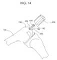
- FIG. 14is a perspective view of the condyle of a host bone illustrating a method of inserting an shaped allograft plug into a cutout formed at a recipient site using a tamp.
- FIG. 15is a front elevational view of the condyle of a host bone illustrating another method of inserting a shaped allograft plug into a cutout formed at a recipient site using a suture.
- FIG. 16is a perspective view of a guide plate with a removable guide cylinder for assisting in removing and shaping a cylindrically shaped allograft plug from a donor bone.
- FIG. 17is a top perspective view of a cannulated burring shell for removing cancellous material and shaping a conically shaped allograft plug.
- FIG. 18is a cross-sectional view of a sleeve placed about an allograft plug having a cylindrical shaped cancellous stalk and a guide pin inserted through the sleeve and partially into the cancellous stalk.
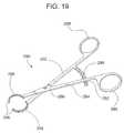
- FIG. 19is a perspective view of a pair of specially configured forceps for handling and manipulating a shaped allograft plug.
- FIG. 20is a front elevational view of a template having cut slots for removing and shaping a rectilinear allograft plug from a donor bone.
- FIG. 21is a cross-sectional view of the template taken along line B-B of FIG. 20 .
- FIG. 22is a cross-sectional view of another embodiment of a template, similar to the template shown in FIGS. 20 and 21 , but adapted for preparing a recipient site on a host bone to receive a rectilinear allograft plug.
- FIG. 1there is shown a device 100 suitable for cutting and forming a cylindrically shaped allograft plug 124 from a donor bone 120 in accordance with one aspect of the invention.
- the device 100itself includes a clamp assembly 102 and a tubular crown saw 104 .
- the clamp assembly 102includes two vertically extending clamp pads 106 , 108 , that can be moved with respect to each other by rotation of a linear screw mechanism 110 .
- the crown saw 104is directed towards and linearly movable with respect to the clamp assembly 102 .
- the crown sawcan pass through a vertical alignment plate 112 joined to a base 114 onto which the clamp assembly is also mounted.
- a donor bone 120 or a portion thereof having on its surface healthy cartilageis received between the clamp pads 106 , 108 and the clamp pads are moved together to grasp and hold the donor bone in alignment with the crown saw 104 .
- the donor bone 120can be received in the clamp assembly 102 such that a condyle 122 corresponding to a donor site on the donor bone 120 is positioned towards the crown saw 104 .
- the rotating tubular crown saw 104is moved towards and into the donor site 122 to form a cylindrical cut into the donor bone 120 , after which the crown saw can be removed.
- the cylindrically shaped bone material 124 produced by the cylindrical cut and that will correspond to the allograft plugcan then be removed from the remainder of the donor bone 120 by, for example, transecting the donor bone with a saw or by propagating a crack through the donor bone with a tamp or similar device.
- the removed cylindrical shaped bone material 124has a cartilage plate 126 corresponding to the outer surface of the donor bone 120 and on which healthy cartilage is located. Extending from the cartilage plate 126 is cancellous bone tissue 128 from the interior portion of the donor bone 120 .
- the donor bone 120 and the crown saw 104are preferably arranged so that the contour of the cartilage plate 126 corresponds to the portion of the host bone which is to be repaired.
- the cylindrically cut bone materialcan be shaped by any variously suitable subsequent shaping operation to remove cancellous bone tissue and form a cancellous stalk extending from the cartilage plate. Removing cancellous bone tissue results in the cancellous stalk having a reduced cross section compared to the cross-section of the cartilage plate.
- cancellous bone tissue on the allograft plugcould contain antigenic material, reducing the amount of cancellous bone tissue transplanted to the host reduces the possibility of an adverse reaction within the host.
- Another advantage of shaping the allograft plug to form a cancellous stalkis that the stalk provides an anchor-like structure that assists in anchoring the allograft plug into a recipient site on the host bone.
- a related advantageis that, by removing cancellous tissue from the cancellous stalk, the amount of cancellous tissue that must be accommodated by the host bone during transplantation is reduced. Accordingly, the size of the cutout that must be formed into a recipient site on the host bone is likewise reduced thereby requiring less trauma to the host bone.
- the finished allograft plugcan have any suitable shape.
- an allograft plug 130having a circular cartilage plate 132 and a cylindrical cancellous stalk 134 of cancellous bone tissue extending therefrom.
- the cartilage plate 132has a generally circular perimeter of a first diameter and includes healthy cartilage from the donor intact on subchondral bone tissue 136 .
- On the underside of the cartilage plate 132there may also be a thin layer of cancellous bone tissue 138 which corresponds to the first diameter.
- the cylindrically shaped cancellous stalk 134extends from the thin layer of cancellous bone tissue 138 and has a second perimeter or second diameter reduced in size with respect to the first diameter. The reduction in size of the second perimeter compared to the first perimeter is the result of removing cancellous bone tissue to form the stalk.
- the circular cartilage plate 132 and the cylindrical cancellous stalk 134are coaxial.
- an allograft plug 140having circular cartilage plate 142 and a generally conical cancellous stalk 144 extending therefrom.
- the cartilage plate 142again has a first perimeter of a given first diameter while the concial perimeter of the cancellous stalk tapers so as to progressively reduce in diameter as the stalk extends from the cartilage plate.
- the circular cartilage plate 142 and the conical cancellous stalkare coaxial.
- the cancellous stalkmay have a stepped shape with each step having a reduced perimeter or diameter compared to the first perimeter of the cartilage plate.
- an allograft plug 150having rectangular cartilage plate 152 with a tapering or rectangular pyramid-shaped cancellous stalk 154 .
- the tapering of the cancellous stalk 154results in a progressive reduction of its cross-section with respect to the cross-section of the rectangular cartilage plate 152 .
- an allograft plug 160having a triangular cartilage plate 162 and a tapering triangular pyramid-shaped cancellous stalk 164 extending therefrom.
- the rectangular and triangular cartilage platescan have respective rectangular and triangular cross-sectioned stalks extending therefrom.
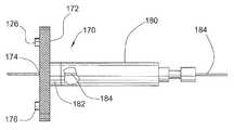
- the template 170includes a flat, circular template plate 172 through the center of which is disposed a guide aperture 174 . From one surface of the template plate 172 there projects a short distance a plurality of sharp teeth 176 .
- the teeth 176are preferably arranged in a circular pattern concentric with the circular template plate 172 .
- the templatepreferably also includes a detachable handle 180 that engages a corresponding engagement structure 182 on the opposite surface of the plate 172 from which the teeth 176 project.
- the handle 180 and plate 172can be engaged by, for example, a twist lock mechanism.
- the guide aperture 174can continue through the detachable handle 180 as well.
- the guide aperture 174is adapted to receive a guide pin 184 in a sliding fit such that the guide pin 184 can be inserted through the center of the plate 172 .
- a jointsuch as a knee joint of the patient being treated is first manipulated to expose the cartilage defect on the surface of a condyle 192 of a host bone 190 .
- the template 170is attached via the sharp, projecting teeth to the condyle 192 at a location corresponding to the defect.
- the circular pattern of the teeth projecting from the templatecorresponds to the area of the defect.
- the handle 180can be reattached to the template 170 and the template pull over the guide pin and removed from the condyle 192 .
- the guide pincan be inserted with the handle remaining attached to the template. Thereafter, the guide pin 184 remains inserted into the condyle 192 as illustrated in FIG. 9 .
- a shaped drill bit, burr, or cutting disccan be employed.
- the shape and dimensions of the drill bit, burr or cutting disc, which will determine the shape and dimension of the formed cutout,may correspond to the allograft that is to be transplanted.
- An embodiment of such a drill bit 200is illustrated in FIG. 10 . Disposed along the central axis of the drill bit 200 is a tube or cannula 202 adapted to receive the guide pin.
- the drill bit 200also includes a circular counter-bore forming element 204 and a conical-shaped cutting body 206 extending from the counter-bore forming element.
- the surface of the counter-bore forming element 204 and the cutting body 206can include flutes or other suitable cutting structures.
- a different drill bit, burr, or cutting disccan be utilized.
- FIG. 11there is illustrated a cannulated drill bit 210 having a circular counter-bore forming element 214 and a cylindrical cutting body 216 .
- the conically cannulated drill bit 200(or burr or cutting disc when used) is slid onto the guide pin 184 and placed proximate the host bone 190 such that the cutting body 204 is proximate the cartilage defect.
- the drill bit 200can be rotated as indicated, either by hand or by a powered device, to cut into and remove the cartilage defect and the associated bone material thereby forming the cutout. Where desirable, lubrication can be supplied to facilitate cutting. Referring to FIG.
- the shape of the cutout 220 formed into the host bone 190will correspond to the shape of the drill bit used including having a conical void 222 and a circular counter bore 224 proximate the surface of the condyle 192 .
- the formed cutoutwill have a corresponding shape including a circular counter-bore and a cylindrical void.
- the shaped drill bits, burrs, and cutting disccan be used to make finishing cuts with different devices used to make initial cuts into the recipient site.
- a correspondingly shaped conical allograft plug 140can be inserted into the shaped cutout 220 at the recipient site using a tamp 228 if necessary.
- the allograft plug 140 and cutout 220are sized to provide a close fit and, more preferably, a slight press fit, when engaged.
- the shaped cancellous stalk 144is received deep into the cutout 220 and thus functions to anchor the allograft plug 140 to the host bone 190 .
- the cartilage plate 142will be accommodated in the counter bore 224 such that the healthy cartilage of the allograft plug 140 aligns with the healthy cartilage on condyle 192 of the host bone 190 . Overtime, the cancellous tissue and cartilage plate will permanently graft with the healthy bone tissue.
- FIG. 15a method of implanting a conically shaped allograft plug 140 by the use of sutures is illustrated.
- a pair of parallel holes 230are cut into the outline of the cutout 220 and through to the opposite side of the host bone 190 .
- a third hole 232is cut transversely across the cancellous stalk 144 of the conical allograft plug 140 .
- a flexible suture 234 or linecan be run through the hole 232 in the cancellous stalk 144 with the ends of the suture run through holes 230 in the cutout 220 and out the opposite side of the host bone 190 .
- Preparing the recipient site and removing and shaping an allograft plug for transplanting into the recipient sitecan occur simultaneously or, in some embodiments, the allograft plug can be removed and shaped in advance of preparing the recipient site. Moreover, the preparation of an allograft plug can occur at a different location than the where the insertion of the allograft plug is to occur. To preserve an allograft plug prior to insertion, the allograft plug can be cryogenically preserved. This is an alternative to preparing and transplanting a fresh allograft plug.
- a guide plate 240 as illustrated in FIG. 16can be used to guide various crown saw cuts into a donor bone 242 .
- the guide plateincludes a generally rectangular base plate 244 that is curved or cambered to fit on a condyle of the donor bone and from one surface of which projects a circular guide cylinder 246 .
- the guide cylinder 246defines a hollow bore 248 of a first diameter that is disposed through the base plate 244 .
- Slidably receivable in the guide cylinder 246is a smaller second guide cylinder 250 through which is disposed a second hollow bore 252 of a second, smaller diameter.
- the guide plate 240also includes a plurality of short sharp teeth 254 projecting from a surface of the base plate 244 opposite the guide cylinder 246 .
- the guide plate 240 with the second guide cylinder 250 insertedis attached to the donor bone 242 on a surface diametrically opposite of the donor site 243 .
- the teeth 254help attach the guide plate to the donor bone 242 and can be inserted into the donor bone by thumb pressure or a light tamp.
- a tubular crown sawhaving a diameter slightly less than diameter of the second hollow bore 252 of the guide plate 240 is inserted through the second hollow bore and into the donor bone.
- the first cutis made into the donor bone 242 from the location of the guide plate 240 opposite the donor site 243 to a point a proximate the cartilage plate of the donor site and more preferably only a few millimeters from the cartilage plate.
- the second, smaller guide cylinder 250is then removed from the guide plate 240 .
- a second crown saw, larger than the first crown saw but with a diameter adapted to be slidably received into the first hollow bore 248 of the guide plate 240is inserted through the first hollow bore and across the donor bone 242 , thereby detaching a portion of bone tissue 258 from the donor bones
- the detached bone tissuecan then be trimmed to a desired length, for example, as measured from the cartilage plate to the cancellous tissue, to produce the allograft plug 130 having the cylindrical cancellous stalk 134 as illustrated in FIG. 2 .
- the guide platehelps avoid injury to adjacent normal cartilage on the donor bone.
- the guide plate 240can be used in conjunction with a clamping device of the type illustrated and described with respect to FIG. 1 .
- the guide plate 240can be used with only the first guide cylinder 246 and the second, larger diameter crown saw to produce a cylindrical allograft plug that can be subsequently shaped.
- a cannulated burring shellcan be used in conjunction with a specially adapted sleeve to further remove cancellous tissue from an allograft plug having a cylindrically—shaped stalk.
- the cannulated burring shell 260has a hollow conical shell body 262 with a guide aperture 264 disposed through the tip of the cone to provide the cannulated feature.
- the cannulated burring shell 264can also include a circular burring disk 266 that extends annularly outward from the base of the conical shell body 262 .
- the interior surface of the conical shell body 262 and the underside of the burring disc 266are adapted to grate or remove cannellous bone tissue.
- the specially adapted sleeve 270is first placed about the cylindrical allograft plug 130 .
- the sleeve 270includes a tubular sleeve body 272 and a base plate 274 having a centrally located guide aperture 276 disposed therein.
- the sleeve 270is placed about the allograft plug 130 such that the tubular sleeve body 272 receives the cylindrical cancellous stalk 134 .
- Another elongated guide pin 278is inserted through the guide aperture 276 and partially into the cancellous tissue of the stalk 134 as illustrated.
- the guide pin 278will be concentrically aligned within the cancellous stalk.
- the sleeve 270can then be removed and the cannullated burring shell 260 of FIG. 17 , via its guide aperture 264 , slide onto the guide pin so that the shell body 262 aligns with the cylindrical cancellous stalk.
- rotation of the cannulated burring shell 260will remove cancellous tissue from the stalk and thereby form the conical shape.
- the burring disk 266can remove or smooth the cancellous tissue on the underside of the allograft plug cartilage plate.
- the forceps 280can include first and second lever arms 282 , 284 that intersect and are pivotally joined at a pivot point 286 .
- an eyelet 288that can accommodate an operators fingers.
- Traversing the first lever arm 282is a locking arm 290 that can engage a locking mechanism 292 on the second arm 284 so as to control and fix articulation of the forceps 280 .
- the forceps 280can be made from any suitable material such as, for example, stainless steel.
- curved or semicircular clamps 294 , 296Formed at the working ends of the first and second lever arms 282 , 284 are curved or semicircular clamps 294 , 296 .
- the clamps 294 , 296can be joined to the respective lever arms 282 , 284 at any suitable angle such as, for example, in-line with the lever arms or at right angles with the lever arms.
- a suitable soft material 298such as an elastomer can be coated onto the clamps 294 , 296 .
- the elastomer materialcan be silicone rubber.
- a special template 300 as illustrated in FIGS. 20 and 21can be used.
- the template 300includes a plate 302 having a cambered or curved shaped to adapt the plate for attachment to the condyle surface of a donor bone. Protruding from one surface of the plate 302 are a plurality of sharp teeth 304 to assist in attaching the template to the donor bone.
- the template 300can further include an engagement structure 306 on the plate surface opposite the protruding teeth 304 to engage a detachable handle as described above.
- the illustrated template 300has a rectangular shape, in other embodiments the template can have other suitable shapes depending upon the shape of the allograft plug desired.
- the allograft plugthere is disposed through the plate 302 and within the perimeter outlined by the sharp teeth 304 a plurality of elongated cut slots 310 that are adapted to accommodate a osteotome, chisel, oscillating saw, or other cutting device.
- the illustrated cut slots 310are arranged rectangularly.
- the cut slotscan be arranged in other patterns, such as triangularly.
- the cut slots 310are furthermore disposed into the template 300 on a converging angle such that, when a cutting device is inserted through the cut slots and into the donor bone, the cuts being made will intersect at a point in the cancellous bone tissue. Intersecting the cuts will detach the allograft plug from the donor bone and simultaneously shape the allograft plug and its cancellous stalk. Hence, locating the cut slots 310 within the outline of the teeth 304 enables insertion of the teeth into the donor bone without damaging the healthy cartilage on allograft plug.
- a template 320 as illustrated in FIG. 22can be used.
- the plate 322 of the template 320is similar in shape and configuration to the template 300 of FIGS. 20 and 21 and also includes a plurality of cut slots 330 disposed angularly there through.
- the template 320can be attached to the host bone at a location corresponding to a cartilage defect by utilizing the sharp teeth 324 protruding from the plate 322 .
- the cut slots 330are preferably located outside of the outline of the teeth 324 .
- the template 320can have a guide aperture 328 disposed through the plate 322 generally central of teeth 324 and the cut slots 330 .
- the procedures and instruments describedmay also be applicable to the preparation and transplantation of a shaped autograft plug.
- the removal, shaping, and insertion of an autograft plug from a host site and into a recipient site within the same patientis readily applicable with respect to rectilinear autograft plugs and can be performed using the same instruments.
Landscapes
- Health & Medical Sciences (AREA)
- Life Sciences & Earth Sciences (AREA)
- Orthopedic Medicine & Surgery (AREA)
- Animal Behavior & Ethology (AREA)
- General Health & Medical Sciences (AREA)
- Engineering & Computer Science (AREA)
- Biomedical Technology (AREA)
- Heart & Thoracic Surgery (AREA)
- Veterinary Medicine (AREA)
- Oral & Maxillofacial Surgery (AREA)
- Public Health (AREA)
- Surgery (AREA)
- Transplantation (AREA)
- Cardiology (AREA)
- Vascular Medicine (AREA)
- Dentistry (AREA)
- Nuclear Medicine, Radiotherapy & Molecular Imaging (AREA)
- Medical Informatics (AREA)
- Molecular Biology (AREA)
- Rheumatology (AREA)
- Physical Education & Sports Medicine (AREA)
- Surgical Instruments (AREA)
- Prostheses (AREA)
Abstract
Description
Claims (22)
Priority Applications (1)
| Application Number | Priority Date | Filing Date | Title |
|---|---|---|---|
| US11/677,414US8882774B2 (en) | 2005-10-26 | 2007-02-21 | Instrumentation for the preparation and transplantation of osteochondral allografts |
Applications Claiming Priority (2)
| Application Number | Priority Date | Filing Date | Title |
|---|---|---|---|
| US11/259,749US7371260B2 (en) | 2005-10-26 | 2005-10-26 | Method and instrumentation for the preparation and transplantation of osteochondral allografts |
| US11/677,414US8882774B2 (en) | 2005-10-26 | 2007-02-21 | Instrumentation for the preparation and transplantation of osteochondral allografts |
Related Parent Applications (1)
| Application Number | Title | Priority Date | Filing Date |
|---|---|---|---|
| US11/259,749DivisionUS7371260B2 (en) | 2005-10-26 | 2005-10-26 | Method and instrumentation for the preparation and transplantation of osteochondral allografts |
Publications (2)
| Publication Number | Publication Date |
|---|---|
| US20070135917A1 US20070135917A1 (en) | 2007-06-14 |
| US8882774B2true US8882774B2 (en) | 2014-11-11 |
Family
ID=37986300
Family Applications (4)
| Application Number | Title | Priority Date | Filing Date |
|---|---|---|---|
| US11/259,749Expired - Fee RelatedUS7371260B2 (en) | 2005-10-26 | 2005-10-26 | Method and instrumentation for the preparation and transplantation of osteochondral allografts |
| US11/677,414Active2027-09-04US8882774B2 (en) | 2005-10-26 | 2007-02-21 | Instrumentation for the preparation and transplantation of osteochondral allografts |
| US11/678,475Expired - Fee RelatedUS8523864B2 (en) | 2005-10-26 | 2007-02-23 | Instrumentation for the preparation and transplantation of osteochondral allografts |
| US11/678,453ActiveUS7550007B2 (en) | 2005-10-26 | 2007-02-23 | Osteochondral allografts |
Family Applications Before (1)
| Application Number | Title | Priority Date | Filing Date |
|---|---|---|---|
| US11/259,749Expired - Fee RelatedUS7371260B2 (en) | 2005-10-26 | 2005-10-26 | Method and instrumentation for the preparation and transplantation of osteochondral allografts |
Family Applications After (2)
| Application Number | Title | Priority Date | Filing Date |
|---|---|---|---|
| US11/678,475Expired - Fee RelatedUS8523864B2 (en) | 2005-10-26 | 2007-02-23 | Instrumentation for the preparation and transplantation of osteochondral allografts |
| US11/678,453ActiveUS7550007B2 (en) | 2005-10-26 | 2007-02-23 | Osteochondral allografts |
Country Status (1)
| Country | Link |
|---|---|
| US (4) | US7371260B2 (en) |
Cited By (3)
| Publication number | Priority date | Publication date | Assignee | Title |
|---|---|---|---|---|
| US20150313640A1 (en)* | 2014-04-30 | 2015-11-05 | Andres Eduardo O'DALY | Surgical instrument with movable guide and sleeve |
| US10524775B2 (en) | 2015-07-02 | 2020-01-07 | Arthrex, Inc. | Methods of repairing cartilage defects |
| US10524774B2 (en) | 2015-04-02 | 2020-01-07 | Arthrex, Inc. | Method of repairing cartilage defects |
Families Citing this family (179)
| Publication number | Priority date | Publication date | Assignee | Title |
|---|---|---|---|---|
| US20100030340A1 (en)* | 1998-06-30 | 2010-02-04 | Wolfinbarger Jr Lloyd | Plasticized Grafts and Methods of Making and Using Same |
| US20080077251A1 (en)* | 1999-06-07 | 2008-03-27 | Chen Silvia S | Cleaning and devitalization of cartilage |
| US8563232B2 (en) | 2000-09-12 | 2013-10-22 | Lifenet Health | Process for devitalizing soft-tissue engineered medical implants, and devitalized soft-tissue medical implants produced |
| US6293970B1 (en) | 1998-06-30 | 2001-09-25 | Lifenet | Plasticized bone and soft tissue grafts and methods of making and using same |
| USRE43714E1 (en) | 1999-12-15 | 2012-10-02 | Zimmer Orthobiologics, Inc. | Preparation for repairing cartilage defects or cartilage/bone defects in human or animal joints |
| US6610067B2 (en) | 2000-05-01 | 2003-08-26 | Arthrosurface, Incorporated | System and method for joint resurface repair |
| US8177841B2 (en) | 2000-05-01 | 2012-05-15 | Arthrosurface Inc. | System and method for joint resurface repair |
| US6520964B2 (en) | 2000-05-01 | 2003-02-18 | Std Manufacturing, Inc. | System and method for joint resurface repair |
| US7163541B2 (en)* | 2002-12-03 | 2007-01-16 | Arthrosurface Incorporated | Tibial resurfacing system |
| US7678151B2 (en)* | 2000-05-01 | 2010-03-16 | Ek Steven W | System and method for joint resurface repair |
| US20100185294A1 (en)* | 2002-06-04 | 2010-07-22 | Arthrosurface Incorporated | Nanorough Alloy Substrate |
| US7901408B2 (en) | 2002-12-03 | 2011-03-08 | Arthrosurface, Inc. | System and method for retrograde procedure |
| US7914545B2 (en) | 2002-12-03 | 2011-03-29 | Arthrosurface, Inc | System and method for retrograde procedure |
| US8388624B2 (en) | 2003-02-24 | 2013-03-05 | Arthrosurface Incorporated | Trochlear resurfacing system and method |
| US7067123B2 (en) | 2003-04-29 | 2006-06-27 | Musculoskeletal Transplant Foundation | Glue for cartilage repair |
| US7901457B2 (en) | 2003-05-16 | 2011-03-08 | Musculoskeletal Transplant Foundation | Cartilage allograft plug |
| US8187336B2 (en)* | 2003-06-16 | 2012-05-29 | Jamali Amir A | Device and method for reconstruction of osseous skeletal defects |
| GB0325141D0 (en)* | 2003-10-28 | 2003-12-03 | Xiros Plc | Repair of damaged tissue on a bone site |
| AU2004293042A1 (en) | 2003-11-20 | 2005-06-09 | Arthrosurface, Inc. | Retrograde delivery of resurfacing devices |
| US20070231788A1 (en)* | 2003-12-31 | 2007-10-04 | Keyvan Behnam | Method for In Vitro Assay of Demineralized Bone Matrix |
| EP1701729B1 (en) | 2003-12-31 | 2018-05-02 | Warsaw Orthopedic, Inc. | Improved bone matrix compositions and methods |
| WO2006004885A2 (en) | 2004-06-28 | 2006-01-12 | Arthrosurface, Inc. | System for articular surface replacement |
| US7837740B2 (en)* | 2007-01-24 | 2010-11-23 | Musculoskeletal Transplant Foundation | Two piece cancellous construct for cartilage repair |
| US7828853B2 (en) | 2004-11-22 | 2010-11-09 | Arthrosurface, Inc. | Articular surface implant and delivery system |
| US7815926B2 (en) | 2005-07-11 | 2010-10-19 | Musculoskeletal Transplant Foundation | Implant for articular cartilage repair |
| AU2006292224B2 (en) | 2005-09-19 | 2013-08-01 | Histogenics Corporation | Cell-support matrix and a method for preparation thereof |
| US7371260B2 (en)* | 2005-10-26 | 2008-05-13 | Biomet Sports Medicine, Inc. | Method and instrumentation for the preparation and transplantation of osteochondral allografts |
| AU2006308534B2 (en)* | 2005-11-01 | 2013-02-07 | Warsaw Orthopedic, Inc. | Bone matrix compositions and methods |
| US8377066B2 (en) | 2006-02-27 | 2013-02-19 | Biomet Manufacturing Corp. | Patient-specific elbow guides and associated methods |
| US8070752B2 (en) | 2006-02-27 | 2011-12-06 | Biomet Manufacturing Corp. | Patient specific alignment guide and inter-operative adjustment |
| US20150335438A1 (en) | 2006-02-27 | 2015-11-26 | Biomet Manufacturing, Llc. | Patient-specific augments |
| US9918740B2 (en) | 2006-02-27 | 2018-03-20 | Biomet Manufacturing, Llc | Backup surgical instrument system and method |
| US8473305B2 (en) | 2007-04-17 | 2013-06-25 | Biomet Manufacturing Corp. | Method and apparatus for manufacturing an implant |
| US8591516B2 (en) | 2006-02-27 | 2013-11-26 | Biomet Manufacturing, Llc | Patient-specific orthopedic instruments |
| US8241293B2 (en) | 2006-02-27 | 2012-08-14 | Biomet Manufacturing Corp. | Patient specific high tibia osteotomy |
| US7967868B2 (en) | 2007-04-17 | 2011-06-28 | Biomet Manufacturing Corp. | Patient-modified implant and associated method |
| US8092465B2 (en) | 2006-06-09 | 2012-01-10 | Biomet Manufacturing Corp. | Patient specific knee alignment guide and associated method |
| US9339278B2 (en) | 2006-02-27 | 2016-05-17 | Biomet Manufacturing, Llc | Patient-specific acetabular guides and associated instruments |
| US10278711B2 (en) | 2006-02-27 | 2019-05-07 | Biomet Manufacturing, Llc | Patient-specific femoral guide |
| US8407067B2 (en) | 2007-04-17 | 2013-03-26 | Biomet Manufacturing Corp. | Method and apparatus for manufacturing an implant |
| US9345548B2 (en) | 2006-02-27 | 2016-05-24 | Biomet Manufacturing, Llc | Patient-specific pre-operative planning |
| US9289253B2 (en) | 2006-02-27 | 2016-03-22 | Biomet Manufacturing, Llc | Patient-specific shoulder guide |
| US9113971B2 (en) | 2006-02-27 | 2015-08-25 | Biomet Manufacturing, Llc | Femoral acetabular impingement guide |
| US8858561B2 (en) | 2006-06-09 | 2014-10-14 | Blomet Manufacturing, LLC | Patient-specific alignment guide |
| US9907659B2 (en) | 2007-04-17 | 2018-03-06 | Biomet Manufacturing, Llc | Method and apparatus for manufacturing an implant |
| US8568487B2 (en) | 2006-02-27 | 2013-10-29 | Biomet Manufacturing, Llc | Patient-specific hip joint devices |
| US8864769B2 (en) | 2006-02-27 | 2014-10-21 | Biomet Manufacturing, Llc | Alignment guides with patient-specific anchoring elements |
| US9173661B2 (en) | 2006-02-27 | 2015-11-03 | Biomet Manufacturing, Llc | Patient specific alignment guide with cutting surface and laser indicator |
| US8603180B2 (en) | 2006-02-27 | 2013-12-10 | Biomet Manufacturing, Llc | Patient-specific acetabular alignment guides |
| US8608749B2 (en) | 2006-02-27 | 2013-12-17 | Biomet Manufacturing, Llc | Patient-specific acetabular guides and associated instruments |
| US8535387B2 (en) | 2006-02-27 | 2013-09-17 | Biomet Manufacturing, Llc | Patient-specific tools and implants |
| US8298237B2 (en) | 2006-06-09 | 2012-10-30 | Biomet Manufacturing Corp. | Patient-specific alignment guide for multiple incisions |
| US8282646B2 (en) | 2006-02-27 | 2012-10-09 | Biomet Manufacturing Corp. | Patient specific knee alignment guide and associated method |
| US8608748B2 (en) | 2006-02-27 | 2013-12-17 | Biomet Manufacturing, Llc | Patient specific guides |
| US8133234B2 (en) | 2006-02-27 | 2012-03-13 | Biomet Manufacturing Corp. | Patient specific acetabular guide and method |
| US9795399B2 (en) | 2006-06-09 | 2017-10-24 | Biomet Manufacturing, Llc | Patient-specific knee alignment guide and associated method |
| US7879040B2 (en)* | 2006-10-23 | 2011-02-01 | Warsaw Orthopedic, IN | Method and apparatus for osteochondral autograft transplantation |
| US9358029B2 (en) | 2006-12-11 | 2016-06-07 | Arthrosurface Incorporated | Retrograde resection apparatus and method |
| US7780668B2 (en)* | 2007-03-02 | 2010-08-24 | Musculoskeletal Transplant Foundation | Osteochondral allograft cartilage transplant workstation |
| US8435551B2 (en) | 2007-03-06 | 2013-05-07 | Musculoskeletal Transplant Foundation | Cancellous construct with support ring for repair of osteochondral defects |
| CA2945295C (en)* | 2007-06-15 | 2020-01-14 | Warsaw Orthopedic, Inc. | Method of treating tissue |
| WO2008157492A2 (en) | 2007-06-15 | 2008-12-24 | Osteotech, Inc. | Osteoinductive demineralized cancellous bone |
| US9554920B2 (en)* | 2007-06-15 | 2017-01-31 | Warsaw Orthopedic, Inc. | Bone matrix compositions having nanoscale textured surfaces |
| CA2690457C (en) | 2007-06-15 | 2018-02-20 | Osteotech, Inc. | Bone matrix compositions and methods |
| US9492278B2 (en)* | 2007-07-10 | 2016-11-15 | Warsaw Orthopedic, Inc. | Delivery system |
| US20110054408A1 (en)* | 2007-07-10 | 2011-03-03 | Guobao Wei | Delivery systems, devices, tools, and methods of use |
| US20090024224A1 (en)* | 2007-07-16 | 2009-01-22 | Chen Silvia S | Implantation of cartilage |
| US9125743B2 (en)* | 2007-07-16 | 2015-09-08 | Lifenet Health | Devitalization and recellularization of cartilage |
| US20090054906A1 (en)* | 2007-08-24 | 2009-02-26 | Zimmer Orthobiologics, Inc. | Medical device and method for delivering an implant to an anatomical site |
| US8265949B2 (en) | 2007-09-27 | 2012-09-11 | Depuy Products, Inc. | Customized patient surgical plan |
| US8357111B2 (en) | 2007-09-30 | 2013-01-22 | Depuy Products, Inc. | Method and system for designing patient-specific orthopaedic surgical instruments |
| EP2194889B1 (en) | 2007-09-30 | 2015-09-23 | DePuy Products, Inc. | Customized patient-specific orthopaedic surgical instrumentation |
| US8303592B2 (en)* | 2007-10-05 | 2012-11-06 | Biomet Manufacturing Corp. | System for forming a tendon-bone graft |
| US8322256B2 (en)* | 2007-10-05 | 2012-12-04 | Biomet Manufacturing Corp. | System for forming a tendon-bone graft |
| US8202539B2 (en)* | 2007-10-19 | 2012-06-19 | Warsaw Orthopedic, Inc. | Demineralized bone matrix compositions and methods |
| US8439921B2 (en)* | 2008-02-12 | 2013-05-14 | Amir Jamali | Device and method for allograft total hip arthroplasty |
| US8998918B2 (en)* | 2008-02-12 | 2015-04-07 | Amir Jamali | Device and method for allograft and tissue engineered osteochondral graft surface matching, preparation, and implantation |
| US8336182B2 (en)* | 2008-02-26 | 2012-12-25 | Sjoerd Anne Van Valkenburg | Device and method for holding a tool bit |
| EP2262448A4 (en) | 2008-03-03 | 2014-03-26 | Arthrosurface Inc | Bone resurfacing system and method |
| EP2265220A1 (en) | 2008-03-05 | 2010-12-29 | Musculoskeletal Transplant Foundation | Cancellous constructs, cartilage particles and combinations of cancellous constructs and cartilage particles |
| US8152846B2 (en)* | 2008-03-06 | 2012-04-10 | Musculoskeletal Transplant Foundation | Instrumentation and method for repair of meniscus tissue |
| US8801725B2 (en)* | 2008-03-10 | 2014-08-12 | Zimmer Orthobiologics, Inc. | Instruments and methods used when repairing a defect on a tissue surface |
| WO2009154691A2 (en)* | 2008-05-29 | 2009-12-23 | Yale University | Systems, devices and methods for cartilage and bone grafting |
| WO2010093955A1 (en)* | 2009-02-12 | 2010-08-19 | Osteotech,Inc. | Segmented delivery system |
| US8170641B2 (en) | 2009-02-20 | 2012-05-01 | Biomet Manufacturing Corp. | Method of imaging an extremity of a patient |
| US8366719B2 (en) | 2009-03-18 | 2013-02-05 | Integrated Spinal Concepts, Inc. | Image-guided minimal-step placement of screw into bone |
| US10945743B2 (en) | 2009-04-17 | 2021-03-16 | Arthrosurface Incorporated | Glenoid repair system and methods of use thereof |
| AU2010236182A1 (en) | 2009-04-17 | 2011-11-24 | Arthrosurface Incorporated | Glenoid resurfacing system and method |
| WO2010121250A1 (en) | 2009-04-17 | 2010-10-21 | Arthrosurface Incorporated | Glenoid resurfacing system and method |
| KR100962166B1 (en)* | 2009-05-04 | 2010-06-10 | 주식회사 이노바이오써지 | Alveolar-ridge cut and expansion tool for dental implant |
| DE102009028503B4 (en) | 2009-08-13 | 2013-11-14 | Biomet Manufacturing Corp. | Resection template for the resection of bones, method for producing such a resection template and operation set for performing knee joint surgery |
| US8419739B2 (en)* | 2009-08-24 | 2013-04-16 | Amir A. Jamali | Method and apparatus for allograft disc transplantation |
| US8864768B2 (en) | 2009-11-20 | 2014-10-21 | Zimmer Knee Creations, Inc. | Coordinate mapping system for joint treatment |
| JP2013511356A (en) | 2009-11-20 | 2013-04-04 | ニー・クリエイションズ・リミテッド・ライアビリティ・カンパニー | Device for variable angle approach to joints |
| WO2011063260A1 (en) | 2009-11-20 | 2011-05-26 | Knee Creations, Llc | Bone-derived implantable devices for subchondral treatment of joint pain |
| US8951261B2 (en) | 2009-11-20 | 2015-02-10 | Zimmer Knee Creations, Inc. | Subchondral treatment of joint pain |
| US9259257B2 (en) | 2009-11-20 | 2016-02-16 | Zimmer Knee Creations, Inc. | Instruments for targeting a joint defect |
| US8821504B2 (en) | 2009-11-20 | 2014-09-02 | Zimmer Knee Creations, Inc. | Method for treating joint pain and associated instruments |
| EP2501303B1 (en) | 2009-11-20 | 2020-02-12 | Zimmer Knee Creations, Inc. | Navigation and positioning instruments for joint repair |
| WO2011063240A1 (en) | 2009-11-20 | 2011-05-26 | Knee Creations, Llc | Implantable devices for subchondral treatment of joint pain |
| US8834568B2 (en) | 2010-02-04 | 2014-09-16 | Paul S. Shapiro | Surgical technique using a contoured allograft cartilage as a spacer of the carpo-metacarpal joint of the thumb or tarso-metatarsal joint of the toe |
| US8632547B2 (en) | 2010-02-26 | 2014-01-21 | Biomet Sports Medicine, Llc | Patient-specific osteotomy devices and methods |
| US9066727B2 (en) | 2010-03-04 | 2015-06-30 | Materialise Nv | Patient-specific computed tomography guides |
| EP2542165A4 (en) | 2010-03-05 | 2015-10-07 | Arthrosurface Inc | Tibial resurfacing system and method |
| EP2389900B1 (en)* | 2010-05-24 | 2013-03-27 | Episurf Medical AB | An implant for cartilage repair comprising an extending post |
| WO2011149590A1 (en)* | 2010-05-27 | 2011-12-01 | Synthes Usa, Llc | Allogenic articular cavity prosthesis |
| US9113916B2 (en) | 2010-08-31 | 2015-08-25 | Zimmer, Inc. | Drill bit for osteochondral drilling with guiding element and uses thereof |
| US8435305B2 (en) | 2010-08-31 | 2013-05-07 | Zimmer, Inc. | Osteochondral graft delivery device and uses thereof |
| US9271744B2 (en) | 2010-09-29 | 2016-03-01 | Biomet Manufacturing, Llc | Patient-specific guide for partial acetabular socket replacement |
| US9968376B2 (en) | 2010-11-29 | 2018-05-15 | Biomet Manufacturing, Llc | Patient-specific orthopedic instruments |
| US9241745B2 (en) | 2011-03-07 | 2016-01-26 | Biomet Manufacturing, Llc | Patient-specific femoral version guide |
| US9066716B2 (en) | 2011-03-30 | 2015-06-30 | Arthrosurface Incorporated | Suture coil and suture sheath for tissue repair |
| US8715289B2 (en) | 2011-04-15 | 2014-05-06 | Biomet Manufacturing, Llc | Patient-specific numerically controlled instrument |
| US9675400B2 (en) | 2011-04-19 | 2017-06-13 | Biomet Manufacturing, Llc | Patient-specific fracture fixation instrumentation and method |
| US8956364B2 (en) | 2011-04-29 | 2015-02-17 | Biomet Manufacturing, Llc | Patient-specific partial knee guides and other instruments |
| US8668700B2 (en) | 2011-04-29 | 2014-03-11 | Biomet Manufacturing, Llc | Patient-specific convertible guides |
| US8532807B2 (en) | 2011-06-06 | 2013-09-10 | Biomet Manufacturing, Llc | Pre-operative planning and manufacturing method for orthopedic procedure |
| US9084618B2 (en) | 2011-06-13 | 2015-07-21 | Biomet Manufacturing, Llc | Drill guides for confirming alignment of patient-specific alignment guides |
| CN102846409A (en)* | 2011-06-29 | 2013-01-02 | 北京爱康宜诚医疗器材股份有限公司 | Spinous metal particle body |
| US20130001121A1 (en) | 2011-07-01 | 2013-01-03 | Biomet Manufacturing Corp. | Backup kit for a patient-specific arthroplasty kit assembly |
| US8764760B2 (en) | 2011-07-01 | 2014-07-01 | Biomet Manufacturing, Llc | Patient-specific bone-cutting guidance instruments and methods |
| US8597365B2 (en) | 2011-08-04 | 2013-12-03 | Biomet Manufacturing, Llc | Patient-specific pelvic implants for acetabular reconstruction |
| US9066734B2 (en) | 2011-08-31 | 2015-06-30 | Biomet Manufacturing, Llc | Patient-specific sacroiliac guides and associated methods |
| US9295497B2 (en) | 2011-08-31 | 2016-03-29 | Biomet Manufacturing, Llc | Patient-specific sacroiliac and pedicle guides |
| US9386993B2 (en) | 2011-09-29 | 2016-07-12 | Biomet Manufacturing, Llc | Patient-specific femoroacetabular impingement instruments and methods |
| US9301812B2 (en) | 2011-10-27 | 2016-04-05 | Biomet Manufacturing, Llc | Methods for patient-specific shoulder arthroplasty |
| WO2013062848A1 (en) | 2011-10-27 | 2013-05-02 | Biomet Manufacturing Corporation | Patient-specific glenoid guides |
| US9451973B2 (en) | 2011-10-27 | 2016-09-27 | Biomet Manufacturing, Llc | Patient specific glenoid guide |
| KR20130046337A (en) | 2011-10-27 | 2013-05-07 | 삼성전자주식회사 | Multi-view device and contol method thereof, display apparatus and contol method thereof, and display system |
| US9554910B2 (en) | 2011-10-27 | 2017-01-31 | Biomet Manufacturing, Llc | Patient-specific glenoid guide and implants |
| EP2804565B1 (en) | 2011-12-22 | 2018-03-07 | Arthrosurface Incorporated | System for bone fixation |
| EP2806810B1 (en)* | 2012-01-24 | 2018-03-28 | Zimmer, Inc. | Method and system for creating patient-specific instrumentation for chondral graft transfer |
| US9204959B2 (en)* | 2012-02-02 | 2015-12-08 | Smith & Nephew, Inc. | Implantable biologic holder |
| US9237950B2 (en) | 2012-02-02 | 2016-01-19 | Biomet Manufacturing, Llc | Implant with patient-specific porous structure |
| CN104684507B (en)* | 2012-05-07 | 2017-04-19 | 史密夫和内修有限公司 | Compaction pliers having removable cutting inserts |
| WO2014008126A1 (en) | 2012-07-03 | 2014-01-09 | Arthrosurface Incorporated | System and method for joint resurfacing and repair |
| WO2014078705A1 (en) | 2012-11-15 | 2014-05-22 | Allosource | Minced cartilage systems and methods |
| US9060788B2 (en) | 2012-12-11 | 2015-06-23 | Biomet Manufacturing, Llc | Patient-specific acetabular guide for anterior approach |
| US9204977B2 (en) | 2012-12-11 | 2015-12-08 | Biomet Manufacturing, Llc | Patient-specific acetabular guide for anterior approach |
| WO2014130883A2 (en) | 2013-02-22 | 2014-08-28 | Allosource | Cartilage mosaic compositions and methods |
| US9839438B2 (en) | 2013-03-11 | 2017-12-12 | Biomet Manufacturing, Llc | Patient-specific glenoid guide with a reusable guide holder |
| US9579107B2 (en) | 2013-03-12 | 2017-02-28 | Biomet Manufacturing, Llc | Multi-point fit for patient specific guide |
| US9498233B2 (en) | 2013-03-13 | 2016-11-22 | Biomet Manufacturing, Llc. | Universal acetabular guide and associated hardware |
| US9826981B2 (en) | 2013-03-13 | 2017-11-28 | Biomet Manufacturing, Llc | Tangential fit of patient-specific guides |
| AU2014236705B2 (en) | 2013-03-15 | 2018-04-12 | Allosource | Perforated osteochondral allograft compositions |
| US9517145B2 (en) | 2013-03-15 | 2016-12-13 | Biomet Manufacturing, Llc | Guide alignment system and method |
| US9492200B2 (en) | 2013-04-16 | 2016-11-15 | Arthrosurface Incorporated | Suture system and method |
| US9173665B2 (en)* | 2013-09-06 | 2015-11-03 | Zimmer, Inc. | Patient-specific surgical guide for intra-operative production of patient-specific augment |
| US20150112349A1 (en) | 2013-10-21 | 2015-04-23 | Biomet Manufacturing, Llc | Ligament Guide Registration |
| WO2015097334A2 (en)* | 2013-12-26 | 2015-07-02 | Universidad De Málaga | Traction mosaicplasty kit |
| US10624748B2 (en) | 2014-03-07 | 2020-04-21 | Arthrosurface Incorporated | System and method for repairing articular surfaces |
| US11607319B2 (en) | 2014-03-07 | 2023-03-21 | Arthrosurface Incorporated | System and method for repairing articular surfaces |
| US9931219B2 (en) | 2014-03-07 | 2018-04-03 | Arthrosurface Incorporated | Implant and anchor assembly |
| WO2015153442A1 (en)* | 2014-03-31 | 2015-10-08 | The Curators Of The University Of Missouri | System, apparatus, and method for creation and implantation of tissue grafts |
| US10282488B2 (en) | 2014-04-25 | 2019-05-07 | Biomet Manufacturing, Llc | HTO guide with optional guided ACL/PCL tunnels |
| US9408616B2 (en) | 2014-05-12 | 2016-08-09 | Biomet Manufacturing, Llc | Humeral cut guide |
| US9561040B2 (en) | 2014-06-03 | 2017-02-07 | Biomet Manufacturing, Llc | Patient-specific glenoid depth control |
| US9839436B2 (en) | 2014-06-03 | 2017-12-12 | Biomet Manufacturing, Llc | Patient-specific glenoid depth control |
| US9833245B2 (en) | 2014-09-29 | 2017-12-05 | Biomet Sports Medicine, Llc | Tibial tubercule osteotomy |
| US9826994B2 (en) | 2014-09-29 | 2017-11-28 | Biomet Manufacturing, Llc | Adjustable glenoid pin insertion guide |
| US10077420B2 (en) | 2014-12-02 | 2018-09-18 | Histogenics Corporation | Cell and tissue culture container |
| US9820868B2 (en) | 2015-03-30 | 2017-11-21 | Biomet Manufacturing, Llc | Method and apparatus for a pin apparatus |
| CN107567312B (en)* | 2015-05-06 | 2022-06-17 | 卡尔蒂希尔(2009)公司 | Optimized solid substrate, tools for use therewith and use thereof for promoting cell and tissue growth |
| US10568647B2 (en) | 2015-06-25 | 2020-02-25 | Biomet Manufacturing, Llc | Patient-specific humeral guide designs |
| US10226262B2 (en) | 2015-06-25 | 2019-03-12 | Biomet Manufacturing, Llc | Patient-specific humeral guide designs |
| US10722310B2 (en) | 2017-03-13 | 2020-07-28 | Zimmer Biomet CMF and Thoracic, LLC | Virtual surgery planning system and method |
| WO2018182849A1 (en)* | 2017-03-30 | 2018-10-04 | Biomet Manufacturing, Llc | Patient specific reconstructive glenoid systems and methods |
| IT201700042055A1 (en)* | 2017-04-14 | 2018-10-14 | Bone And Joint Solutions Sa | Osteochondral local prosthetic insert |
| US11160663B2 (en) | 2017-08-04 | 2021-11-02 | Arthrosurface Incorporated | Multicomponent articular surface implant |
| US11147567B2 (en)* | 2018-02-28 | 2021-10-19 | Joint Restoration Foundation, Inc. | Methods and devices for restoration of a bone surface |
| US11051829B2 (en) | 2018-06-26 | 2021-07-06 | DePuy Synthes Products, Inc. | Customized patient-specific orthopaedic surgical instrument |
| WO2020107106A1 (en) | 2018-11-27 | 2020-06-04 | Sunnybrook Research Institute | Cartilage slicing apparatus and methods therefor |
| WO2020186099A1 (en) | 2019-03-12 | 2020-09-17 | Arthrosurface Incorporated | Humeral and glenoid articular surface implant systems and methods |
| NL1043315B1 (en)* | 2019-06-27 | 2021-02-01 | Jointsphere B V | Plug-shaped implant for the replacement and regeneration of biological tissue and method for preparing the implant |
| CN112603606A (en)* | 2020-12-28 | 2021-04-06 | 北京市春立正达医疗器械股份有限公司 | Knee joint cartilage prosthesis for local replacement |
| US20220330955A1 (en)* | 2021-04-16 | 2022-10-20 | The Second Affiliated Hospital And Yuying Children's Hospital Of Wenzhou Medical University | A guide plate structure for spine surgery and the production method and usage thereof |
| US12075999B2 (en)* | 2021-11-10 | 2024-09-03 | Arthrex, Inc. | Knotless tensionable fixation systems and surgical methods for repairing tissue defects |
| CN115068023B (en)* | 2022-05-24 | 2025-02-14 | 中国人民解放军联勤保障部队第九二〇医院 | A cartilage partial defect transplantation component |
| WO2025151535A1 (en)* | 2024-01-08 | 2025-07-17 | Hyalex Orthopaedics, Inc. | Metatarsophalangeal joint implants and methods thereof |
Citations (105)
| Publication number | Priority date | Publication date | Assignee | Title |
|---|---|---|---|---|
| US43909A (en) | 1864-08-23 | Hog-snout cutter | ||
| US493730A (en) | 1893-03-21 | Trephine | ||
| US1911873A (en) | 1931-07-21 | 1933-05-30 | Joseph Shapiro | Wafer cutting machine |
| US2573462A (en) | 1947-09-02 | 1951-10-30 | Lindsey Earle | Tubular rotary cutter |
| US2591516A (en) | 1950-05-08 | 1952-04-01 | Victor L Darnell | Dispensing device |
| US3835849A (en)* | 1973-01-26 | 1974-09-17 | Guire G Mc | Bone clamp and adjustable drill guide |
| US3848601A (en) | 1972-06-14 | 1974-11-19 | G Ma | Method for interbody fusion of the spine |
| US3875936A (en)* | 1972-12-18 | 1975-04-08 | Robert G Volz | Trochantaric attachment assembly and method of using same |
| US4007732A (en) | 1975-09-02 | 1977-02-15 | Robert Carl Kvavle | Method for location and removal of soft tissue in human biopsy operations |
| US4010737A (en) | 1971-06-14 | 1977-03-08 | Vilaghy Miklos I | Bone biopsy instrument kit |
| US4059115A (en) | 1976-06-14 | 1977-11-22 | Georgy Stepanovich Jumashev | Surgical instrument for operation of anterior fenestrated spondylodessis in vertebral osteochondrosis |
| US4177797A (en) | 1977-03-04 | 1979-12-11 | Shelby M. Baylis | Rotary biopsy device and method of using same |
| US4341206A (en)* | 1978-12-19 | 1982-07-27 | Synthes Ag | Device for producing a hole in a bone |
| US4416278A (en) | 1979-07-26 | 1983-11-22 | Miller Joseph E | Bone plug cutter |
| US4444180A (en)* | 1982-03-01 | 1984-04-24 | Aktiebolaget Stille-Werner | Surgical instrument for engaging a bony part of the human body and guiding a drill bit into a specific location in the bony part |
| US4528980A (en)* | 1983-10-19 | 1985-07-16 | Howmedica, Inc. | Acetabulum sizer and drill guide |
| US4565192A (en) | 1984-04-12 | 1986-01-21 | Shapiro James A | Device for cutting a patella and method therefor |
| US4627853A (en) | 1985-05-29 | 1986-12-09 | American Hospital Supply Corporation | Method of producing prostheses for replacement of articular cartilage and prostheses so produced |
| US4649918A (en) | 1980-09-03 | 1987-03-17 | Custom Medical Devices, Inc. | Bone core removing tool |
| US4741651A (en) | 1986-04-25 | 1988-05-03 | Despres Roger J | Hole saw |
| US4782833A (en) | 1987-02-19 | 1988-11-08 | Thomas A. Einhorn | Bone boring instrument |
| US4904259A (en) | 1988-04-29 | 1990-02-27 | Samuel Itay | Compositions and methods for repair of cartilage and bone |
| US4913143A (en) | 1986-05-28 | 1990-04-03 | The United States Of America As Represented By The Secretary Of The Air Force | Trephine assembly |
| US4936313A (en) | 1987-11-18 | 1990-06-26 | Institut Strauman AG | Power tool for excising a bone or cartilage biopsy |
| WO1991006246A1 (en) | 1989-11-06 | 1991-05-16 | Allen William C | Biopsy device |
| US5041117A (en) | 1989-08-31 | 1991-08-20 | Boehringer Mannheim Corporation | Elbow arthroplasty instrumentation and surgical procedure |
| US5053050A (en) | 1988-04-29 | 1991-10-01 | Samuel Itay | Compositions for repair of cartilage and bone |
| US5139520A (en) | 1990-01-31 | 1992-08-18 | American Cyanamid Company | Method for acl reconstruction |
| US5152763A (en) | 1991-04-02 | 1992-10-06 | Johnson Lanny L | Method for grafting bone |
| US5197967A (en) | 1991-04-02 | 1993-03-30 | Synthes (U.S.A.) | Trephine instrument and method for cutting annular holes |
| US5211647A (en) | 1992-02-19 | 1993-05-18 | Arthrex Inc. | Interference screw and cannulated sheath for endosteal fixation of ligaments |
| US5269786A (en) | 1992-02-20 | 1993-12-14 | Arthrex Inc. | PCL oriented placement tibial guide method |
| US5320626A (en) | 1992-02-19 | 1994-06-14 | Arthrex Inc. | Endoscopic drill guide |
| US5320115A (en) | 1991-01-16 | 1994-06-14 | Applied Biological Concepts | Method and apparatus for arthroscopic knee surgery |
| US5341816A (en) | 1989-11-06 | 1994-08-30 | Allen William C | Biopsy device |
| US5397357A (en) | 1993-02-18 | 1995-03-14 | Arthrex, Inc. | Method for preparing a bone-tendon-bone core graft |
| US5415651A (en) | 1993-02-18 | 1995-05-16 | Arthrex, Inc. | Work station for preparing a bone-tendon-bone core graft |
| US5423823A (en) | 1993-02-18 | 1995-06-13 | Arthrex Inc. | Coring reamer |
| US5489310A (en)* | 1994-06-27 | 1996-02-06 | Mikhail; W. E. Michael | Universal glenoid shoulder prosthesis and method for implanting |
| US5496326A (en) | 1991-06-27 | 1996-03-05 | Johnson; Lanny L. | Fixation screw and method for ligament reconstruction |
| DE19503504A1 (en) | 1994-09-16 | 1996-03-21 | Metrimed Orvosi Mueszergyarto | Instrument set for osteochondral transplant |
| US5513662A (en) | 1991-12-31 | 1996-05-07 | Osteotech, Inc. | Preparation of bone for transplantation |
| US5540692A (en) | 1994-07-13 | 1996-07-30 | Midas Rex Pneumatic Tools, Inc. | Replicator for resecting bone to match a pattern |
| US5562669A (en) | 1994-01-13 | 1996-10-08 | Mcguire; David A. | Cruciate ligament reconstruction with tibial drill guide |
| US5603716A (en) | 1995-02-16 | 1997-02-18 | Arthrex Inc. | Method of ligament reconstruction using double socket graft placement and fixation |
| US5655546A (en) | 1995-06-07 | 1997-08-12 | Halpern; Alan A. | Method for cartilage repair |
| US5733289A (en) | 1992-10-27 | 1998-03-31 | Neoligaments Limited | Ligament graft harvesting |
| US5782835A (en) | 1995-03-07 | 1998-07-21 | Innovasive Devices, Inc. | Apparatus and methods for articular cartilage defect repair |
| US5817098A (en) | 1995-05-17 | 1998-10-06 | Astra Aktiebolag | Drill guide instrument |
| US5827288A (en) | 1997-04-10 | 1998-10-27 | Midas Rex, L.P. | Circular hole forming apparatus |
| US5865834A (en) | 1991-12-13 | 1999-02-02 | Mcguire; David A. | Coring reamer |
| US5885293A (en) | 1997-03-03 | 1999-03-23 | Innovasive Devices, Inc. | Apparatus and method for cutting a surface at a repeatable angle |
| US5895390A (en)* | 1996-09-19 | 1999-04-20 | Biomet, Inc. | Pin placement guide used in making a bone entry hole for implantation of an intramedullary nail |
| US5904717A (en) | 1986-01-28 | 1999-05-18 | Thm Biomedical, Inc. | Method and device for reconstruction of articular cartilage |
| US5919196A (en) | 1995-02-16 | 1999-07-06 | Arthrex, Inc. | Method and apparatus for osteochondral autograft transplantation |
| US5918604A (en) | 1997-02-12 | 1999-07-06 | Arthrex, Inc. | Method of loading tendons into the knee |
| US6007496A (en) | 1996-12-30 | 1999-12-28 | Brannon; James K. | Syringe assembly for harvesting bone |
| US6110178A (en) | 1997-04-25 | 2000-08-29 | Sulzer Orthopadie Ag | Apparatus for the production of endochondral or osteochondral bores |
| US6146385A (en) | 1997-02-11 | 2000-11-14 | Smith & Nephew, Inc. | Repairing cartilage |
| US6179839B1 (en) | 1999-09-20 | 2001-01-30 | Kinetikos Medical Incorporated | Bone fusion apparatus and method |
| US6187329B1 (en) | 1997-12-23 | 2001-02-13 | Board Of Regents Of The University Of Texas System | Variable permeability bone implants, methods for their preparation and use |
| US6231577B1 (en) | 1999-08-12 | 2001-05-15 | James T. Canedy | Device for creating cylindrical bone plugs for patella-patellar tendon-tibia grafts |
| US6242247B1 (en) | 1996-06-04 | 2001-06-05 | Sulzer Orthopedics Ltd. | Method for making cartilage and implants |
| US6280447B1 (en) | 1998-12-23 | 2001-08-28 | Nuvasive, Inc. | Bony tissue resector |
| US20010027322A1 (en) | 1999-07-23 | 2001-10-04 | Bowman Steven M. | Instrument for inserting graft fixation device |
| US6305379B1 (en) | 1996-09-06 | 2001-10-23 | Lifenet | Process for producing osteoinductive bone, and osteoinductive bone produced thereby |
| US20010039455A1 (en) | 2000-03-14 | 2001-11-08 | Timothy Simon | Cartilage repair plug |
| US20020022847A1 (en) | 1998-04-09 | 2002-02-21 | Ray Eddie F. | Methods and instrumentation for vertebral interbody fusion |
| US6375658B1 (en) | 2000-04-28 | 2002-04-23 | Smith & Nephew, Inc. | Cartilage grafting |
| US6395011B1 (en) | 1998-07-17 | 2002-05-28 | Johnson & Johnson | Method and apparatus for harvesting and implanting bone plugs |
| US20020082704A1 (en) | 2000-05-15 | 2002-06-27 | Cryolife, Inc. | Osteochondral transplant techniques |
| US20020095214A1 (en) | 2001-01-16 | 2002-07-18 | Hyde Edward R. | Transosseous core approach and instrumentation for joint replacement and repair |
| US6442814B1 (en) | 1999-04-23 | 2002-09-03 | Spinal Concepts, Inc. | Apparatus for manufacturing a bone dowel |
| US6458144B1 (en) | 1999-12-30 | 2002-10-01 | Osteotech, Inc. | Methods for manufacturing skeletal implants |
| US20030009218A1 (en) | 1997-07-23 | 2003-01-09 | Boucher James A. | Apparatus and method for tibial fixation of soft tissue |
| US6528052B1 (en) | 2000-09-29 | 2003-03-04 | The Board Of Trustees Of The Leland Stanford Junior University | Method for in vivo ex vivo and in vitro repair and regeneration of cartilage and collagen and bone remodeling |
| US6530928B1 (en) | 1999-03-23 | 2003-03-11 | Sulzer Orthopedics Ltd. | Instrument, instrument set and a method for the introduction of an osteochondral transplant |
| US6557226B1 (en) | 1999-04-23 | 2003-05-06 | Michael E. Landry | Apparatus for manufacturing a bone dowel |
| US20030130662A1 (en) | 1998-06-09 | 2003-07-10 | Michelson Gary K. | Device and method for preparing a space between adjacent vertebrae to receive an insert |
| US6591581B2 (en) | 2000-03-08 | 2003-07-15 | Arthrex, Inc. | Method for preparing and inserting round, size specific osteochondral cores in the knee |
| US6592588B1 (en) | 1995-02-16 | 2003-07-15 | Arthrex, Inc. | Apparatus for osteochondral autograft transplantation |
| US6607534B2 (en) | 1990-06-28 | 2003-08-19 | Peter M. Bonutti | Tissue engagement method |
| US6613054B2 (en) | 1998-08-14 | 2003-09-02 | Kyphon Inc. | Systems and methods for placing materials into bone |
| US20030212435A1 (en) | 2002-03-26 | 2003-11-13 | Adam Gold | Handleless clamping device |
| US6685709B2 (en) | 1996-06-04 | 2004-02-03 | Joseph H. Sklar | Apparatus and method for reconstructing ligaments |
| US6696073B2 (en) | 1999-02-23 | 2004-02-24 | Osteotech, Inc. | Shaped load-bearing osteoimplant and methods of making same |
| US6727224B1 (en) | 1999-02-01 | 2004-04-27 | Genetics Institute, Llc. | Methods and compositions for healing and repair of articular cartilage |
| US6740484B1 (en) | 1999-04-13 | 2004-05-25 | Organ Recovery Systems, Inc. | Method of cryopreservation of tissues by vitrification |
| US20040106928A1 (en) | 2002-12-03 | 2004-06-03 | Steven Ek | Tibial resurfacing system |
| US20040162622A1 (en) | 2000-03-14 | 2004-08-19 | Chondosite, Llc | Cartilage repair plug |
| US20040186482A1 (en)* | 2003-03-21 | 2004-09-23 | Kolb Eric D. | Modular drill guide |
| US6796977B2 (en) | 2001-09-28 | 2004-09-28 | Depuy Mitek, Inc. | Variable graft tensioner |
| US20040210227A1 (en)* | 2003-02-03 | 2004-10-21 | Kinetikos Medical, Inc. | Compression screw apparatuses, systems and methods |
| US20040230303A1 (en) | 2003-05-16 | 2004-11-18 | Gomes Katherine A. | Cartilage allograft plug |
| US6835377B2 (en) | 1998-05-13 | 2004-12-28 | Osiris Therapeutics, Inc. | Osteoarthritis cartilage regeneration |
| US20050064042A1 (en) | 2003-04-29 | 2005-03-24 | Musculoskeletal Transplant Foundation | Cartilage implant plug with fibrin glue and method for implantation |
| US20050222576A1 (en) | 2004-03-18 | 2005-10-06 | Kick George F | Expandable medical access device |
| US6962592B2 (en) | 2002-09-11 | 2005-11-08 | Cortek, Inc. | Allograft implant cutting machine |
| US20060142775A1 (en) | 2004-12-29 | 2006-06-29 | Depuy Mitek, Inc. | Surgical tool with cannulated rotary tip |
| US20070093896A1 (en) | 2005-10-26 | 2007-04-26 | Malinin Theodore I | Method and instrumentation for the preparation and transplantation of osteochondral allografts |
| US7231815B2 (en)* | 2004-12-02 | 2007-06-19 | Construction Technology Laboratories, Inc. | Relative humidity probe for concrete |
| US7241316B2 (en) | 2002-06-13 | 2007-07-10 | Douglas G Evans | Devices and methods for treating defects in the tissue of a living being |
| US20070276506A1 (en) | 2006-05-25 | 2007-11-29 | Biomet Manufacturing Corp. | Demineralized osteochondral plug |
| US7347130B2 (en) | 2003-12-16 | 2008-03-25 | Stryker Spine | Apparatus and method for cutting spinal implants |
| US20090093853A1 (en) | 2007-10-05 | 2009-04-09 | Biomet Manufacturing Corp. | System For Forming A Tendon-Bone Graft |
Family Cites Families (3)
| Publication number | Priority date | Publication date | Assignee | Title |
|---|---|---|---|---|
| US560316A (en)* | 1896-05-19 | Annealing-box | ||
| US6630928B1 (en)* | 1999-10-01 | 2003-10-07 | Hewlett-Packard Development Company, L.P. | Method and apparatus for touch screen data entry |
| US6628052B2 (en)* | 2001-10-05 | 2003-09-30 | Hewlett-Packard Development Company, L.P. | Enhanced electron field emitter spindt tip and method for fabricating enhanced spindt tips |
- 2005
- 2005-10-26USUS11/259,749patent/US7371260B2/ennot_activeExpired - Fee Related
- 2007
- 2007-02-21USUS11/677,414patent/US8882774B2/enactiveActive
- 2007-02-23USUS11/678,475patent/US8523864B2/ennot_activeExpired - Fee Related
- 2007-02-23USUS11/678,453patent/US7550007B2/enactiveActive
Patent Citations (115)
| Publication number | Priority date | Publication date | Assignee | Title |
|---|---|---|---|---|
| US43909A (en) | 1864-08-23 | Hog-snout cutter | ||
| US493730A (en) | 1893-03-21 | Trephine | ||
| US1911873A (en) | 1931-07-21 | 1933-05-30 | Joseph Shapiro | Wafer cutting machine |
| US2573462A (en) | 1947-09-02 | 1951-10-30 | Lindsey Earle | Tubular rotary cutter |
| US2591516A (en) | 1950-05-08 | 1952-04-01 | Victor L Darnell | Dispensing device |
| US4010737A (en) | 1971-06-14 | 1977-03-08 | Vilaghy Miklos I | Bone biopsy instrument kit |
| US3848601A (en) | 1972-06-14 | 1974-11-19 | G Ma | Method for interbody fusion of the spine |
| US3875936A (en)* | 1972-12-18 | 1975-04-08 | Robert G Volz | Trochantaric attachment assembly and method of using same |
| US3835849A (en)* | 1973-01-26 | 1974-09-17 | Guire G Mc | Bone clamp and adjustable drill guide |
| US4007732A (en) | 1975-09-02 | 1977-02-15 | Robert Carl Kvavle | Method for location and removal of soft tissue in human biopsy operations |
| US4059115A (en) | 1976-06-14 | 1977-11-22 | Georgy Stepanovich Jumashev | Surgical instrument for operation of anterior fenestrated spondylodessis in vertebral osteochondrosis |
| US4177797A (en) | 1977-03-04 | 1979-12-11 | Shelby M. Baylis | Rotary biopsy device and method of using same |
| US4341206A (en)* | 1978-12-19 | 1982-07-27 | Synthes Ag | Device for producing a hole in a bone |
| US4416278A (en) | 1979-07-26 | 1983-11-22 | Miller Joseph E | Bone plug cutter |
| US4649918A (en) | 1980-09-03 | 1987-03-17 | Custom Medical Devices, Inc. | Bone core removing tool |
| US4444180A (en)* | 1982-03-01 | 1984-04-24 | Aktiebolaget Stille-Werner | Surgical instrument for engaging a bony part of the human body and guiding a drill bit into a specific location in the bony part |
| US4528980A (en)* | 1983-10-19 | 1985-07-16 | Howmedica, Inc. | Acetabulum sizer and drill guide |
| US4565192A (en) | 1984-04-12 | 1986-01-21 | Shapiro James A | Device for cutting a patella and method therefor |
| US4627853A (en) | 1985-05-29 | 1986-12-09 | American Hospital Supply Corporation | Method of producing prostheses for replacement of articular cartilage and prostheses so produced |
| US5904717A (en) | 1986-01-28 | 1999-05-18 | Thm Biomedical, Inc. | Method and device for reconstruction of articular cartilage |
| US4741651A (en) | 1986-04-25 | 1988-05-03 | Despres Roger J | Hole saw |
| US4913143A (en) | 1986-05-28 | 1990-04-03 | The United States Of America As Represented By The Secretary Of The Air Force | Trephine assembly |
| US4782833A (en) | 1987-02-19 | 1988-11-08 | Thomas A. Einhorn | Bone boring instrument |
| US4936313A (en) | 1987-11-18 | 1990-06-26 | Institut Strauman AG | Power tool for excising a bone or cartilage biopsy |
| US4904259A (en) | 1988-04-29 | 1990-02-27 | Samuel Itay | Compositions and methods for repair of cartilage and bone |
| US5053050A (en) | 1988-04-29 | 1991-10-01 | Samuel Itay | Compositions for repair of cartilage and bone |
| US5041117A (en) | 1989-08-31 | 1991-08-20 | Boehringer Mannheim Corporation | Elbow arthroplasty instrumentation and surgical procedure |
| WO1991006246A1 (en) | 1989-11-06 | 1991-05-16 | Allen William C | Biopsy device |
| US5341816A (en) | 1989-11-06 | 1994-08-30 | Allen William C | Biopsy device |
| US5139520A (en) | 1990-01-31 | 1992-08-18 | American Cyanamid Company | Method for acl reconstruction |
| US6607534B2 (en) | 1990-06-28 | 2003-08-19 | Peter M. Bonutti | Tissue engagement method |
| US5320115A (en) | 1991-01-16 | 1994-06-14 | Applied Biological Concepts | Method and apparatus for arthroscopic knee surgery |
| US5197967A (en) | 1991-04-02 | 1993-03-30 | Synthes (U.S.A.) | Trephine instrument and method for cutting annular holes |
| US5152763A (en) | 1991-04-02 | 1992-10-06 | Johnson Lanny L | Method for grafting bone |
| US5496326A (en) | 1991-06-27 | 1996-03-05 | Johnson; Lanny L. | Fixation screw and method for ligament reconstruction |
| US5865834A (en) | 1991-12-13 | 1999-02-02 | Mcguire; David A. | Coring reamer |
| US5513662A (en) | 1991-12-31 | 1996-05-07 | Osteotech, Inc. | Preparation of bone for transplantation |
| US5211647A (en) | 1992-02-19 | 1993-05-18 | Arthrex Inc. | Interference screw and cannulated sheath for endosteal fixation of ligaments |
| US5320626A (en) | 1992-02-19 | 1994-06-14 | Arthrex Inc. | Endoscopic drill guide |
| US5269786A (en) | 1992-02-20 | 1993-12-14 | Arthrex Inc. | PCL oriented placement tibial guide method |
| US5733289A (en) | 1992-10-27 | 1998-03-31 | Neoligaments Limited | Ligament graft harvesting |
| US5397357A (en) | 1993-02-18 | 1995-03-14 | Arthrex, Inc. | Method for preparing a bone-tendon-bone core graft |
| US5423823A (en) | 1993-02-18 | 1995-06-13 | Arthrex Inc. | Coring reamer |
| US5415651A (en) | 1993-02-18 | 1995-05-16 | Arthrex, Inc. | Work station for preparing a bone-tendon-bone core graft |
| US5562669A (en) | 1994-01-13 | 1996-10-08 | Mcguire; David A. | Cruciate ligament reconstruction with tibial drill guide |
| US5489310A (en)* | 1994-06-27 | 1996-02-06 | Mikhail; W. E. Michael | Universal glenoid shoulder prosthesis and method for implanting |
| US5540692A (en) | 1994-07-13 | 1996-07-30 | Midas Rex Pneumatic Tools, Inc. | Replicator for resecting bone to match a pattern |
| DE19503504A1 (en) | 1994-09-16 | 1996-03-21 | Metrimed Orvosi Mueszergyarto | Instrument set for osteochondral transplant |
| US6592588B1 (en) | 1995-02-16 | 2003-07-15 | Arthrex, Inc. | Apparatus for osteochondral autograft transplantation |
| US5919196A (en) | 1995-02-16 | 1999-07-06 | Arthrex, Inc. | Method and apparatus for osteochondral autograft transplantation |
| US5603716A (en) | 1995-02-16 | 1997-02-18 | Arthrex Inc. | Method of ligament reconstruction using double socket graft placement and fixation |
| US5785714A (en) | 1995-02-16 | 1998-07-28 | Arthrex, Inc. | Method of ACL reconstruction using double socket graft placement and fixation |
| US5782835A (en) | 1995-03-07 | 1998-07-21 | Innovasive Devices, Inc. | Apparatus and methods for articular cartilage defect repair |
| US6017348A (en) | 1995-03-07 | 2000-01-25 | Innovasive Devices, Inc. | Apparatus and methods for articular cartilage defect repair |
| US5817098A (en) | 1995-05-17 | 1998-10-06 | Astra Aktiebolag | Drill guide instrument |
| US5655546A (en) | 1995-06-07 | 1997-08-12 | Halpern; Alan A. | Method for cartilage repair |
| US6179871B1 (en) | 1995-06-07 | 2001-01-30 | Alan A. Halpern | Means for cartilage repair |
| US6685709B2 (en) | 1996-06-04 | 2004-02-03 | Joseph H. Sklar | Apparatus and method for reconstructing ligaments |
| US6387693B2 (en) | 1996-06-04 | 2002-05-14 | Sulzer Orthopedics Ltd. | Method for producing cartilage tissue and implants for repairing enchondral and osteochondral defects as well as arrangement for carrying out the method |
| US6242247B1 (en) | 1996-06-04 | 2001-06-05 | Sulzer Orthopedics Ltd. | Method for making cartilage and implants |
| US6305379B1 (en) | 1996-09-06 | 2001-10-23 | Lifenet | Process for producing osteoinductive bone, and osteoinductive bone produced thereby |
| US5895390A (en)* | 1996-09-19 | 1999-04-20 | Biomet, Inc. | Pin placement guide used in making a bone entry hole for implantation of an intramedullary nail |
| US6007496A (en) | 1996-12-30 | 1999-12-28 | Brannon; James K. | Syringe assembly for harvesting bone |
| US6146385A (en) | 1997-02-11 | 2000-11-14 | Smith & Nephew, Inc. | Repairing cartilage |
| US6358253B1 (en) | 1997-02-11 | 2002-03-19 | Smith & Newhew Inc | Repairing cartilage |
| US5918604A (en) | 1997-02-12 | 1999-07-06 | Arthrex, Inc. | Method of loading tendons into the knee |
| US5885293A (en) | 1997-03-03 | 1999-03-23 | Innovasive Devices, Inc. | Apparatus and method for cutting a surface at a repeatable angle |
| US5827288A (en) | 1997-04-10 | 1998-10-27 | Midas Rex, L.P. | Circular hole forming apparatus |
| US6110178A (en) | 1997-04-25 | 2000-08-29 | Sulzer Orthopadie Ag | Apparatus for the production of endochondral or osteochondral bores |
| US20030009218A1 (en) | 1997-07-23 | 2003-01-09 | Boucher James A. | Apparatus and method for tibial fixation of soft tissue |
| US6187329B1 (en) | 1997-12-23 | 2001-02-13 | Board Of Regents Of The University Of Texas System | Variable permeability bone implants, methods for their preparation and use |
| US20020022847A1 (en) | 1998-04-09 | 2002-02-21 | Ray Eddie F. | Methods and instrumentation for vertebral interbody fusion |
| US6835377B2 (en) | 1998-05-13 | 2004-12-28 | Osiris Therapeutics, Inc. | Osteoarthritis cartilage regeneration |
| US20030130662A1 (en) | 1998-06-09 | 2003-07-10 | Michelson Gary K. | Device and method for preparing a space between adjacent vertebrae to receive an insert |
| US6395011B1 (en) | 1998-07-17 | 2002-05-28 | Johnson & Johnson | Method and apparatus for harvesting and implanting bone plugs |
| US6613054B2 (en) | 1998-08-14 | 2003-09-02 | Kyphon Inc. | Systems and methods for placing materials into bone |
| US6280447B1 (en) | 1998-12-23 | 2001-08-28 | Nuvasive, Inc. | Bony tissue resector |
| US6727224B1 (en) | 1999-02-01 | 2004-04-27 | Genetics Institute, Llc. | Methods and compositions for healing and repair of articular cartilage |
| US6696073B2 (en) | 1999-02-23 | 2004-02-24 | Osteotech, Inc. | Shaped load-bearing osteoimplant and methods of making same |
| US6530928B1 (en) | 1999-03-23 | 2003-03-11 | Sulzer Orthopedics Ltd. | Instrument, instrument set and a method for the introduction of an osteochondral transplant |
| US6740484B1 (en) | 1999-04-13 | 2004-05-25 | Organ Recovery Systems, Inc. | Method of cryopreservation of tissues by vitrification |
| US6557226B1 (en) | 1999-04-23 | 2003-05-06 | Michael E. Landry | Apparatus for manufacturing a bone dowel |
| US6442814B1 (en) | 1999-04-23 | 2002-09-03 | Spinal Concepts, Inc. | Apparatus for manufacturing a bone dowel |
| US20010027322A1 (en) | 1999-07-23 | 2001-10-04 | Bowman Steven M. | Instrument for inserting graft fixation device |
| US6231577B1 (en) | 1999-08-12 | 2001-05-15 | James T. Canedy | Device for creating cylindrical bone plugs for patella-patellar tendon-tibia grafts |
| US6179839B1 (en) | 1999-09-20 | 2001-01-30 | Kinetikos Medical Incorporated | Bone fusion apparatus and method |
| US6458144B1 (en) | 1999-12-30 | 2002-10-01 | Osteotech, Inc. | Methods for manufacturing skeletal implants |
| US6591581B2 (en) | 2000-03-08 | 2003-07-15 | Arthrex, Inc. | Method for preparing and inserting round, size specific osteochondral cores in the knee |
| US20040162622A1 (en) | 2000-03-14 | 2004-08-19 | Chondosite, Llc | Cartilage repair plug |
| US20010039455A1 (en) | 2000-03-14 | 2001-11-08 | Timothy Simon | Cartilage repair plug |
| US6375658B1 (en) | 2000-04-28 | 2002-04-23 | Smith & Nephew, Inc. | Cartilage grafting |
| US20020082704A1 (en) | 2000-05-15 | 2002-06-27 | Cryolife, Inc. | Osteochondral transplant techniques |
| US6852114B2 (en) | 2000-05-15 | 2005-02-08 | Cryolife, Inc. | Osteochondral transplant techniques |
| US6488033B1 (en) | 2000-05-15 | 2002-12-03 | Cryolife, Inc. | Osteochondral transplant techniques |
| US6528052B1 (en) | 2000-09-29 | 2003-03-04 | The Board Of Trustees Of The Leland Stanford Junior University | Method for in vivo ex vivo and in vitro repair and regeneration of cartilage and collagen and bone remodeling |
| US20020095214A1 (en) | 2001-01-16 | 2002-07-18 | Hyde Edward R. | Transosseous core approach and instrumentation for joint replacement and repair |
| US6796977B2 (en) | 2001-09-28 | 2004-09-28 | Depuy Mitek, Inc. | Variable graft tensioner |
| US20030212435A1 (en) | 2002-03-26 | 2003-11-13 | Adam Gold | Handleless clamping device |
| US7241316B2 (en) | 2002-06-13 | 2007-07-10 | Douglas G Evans | Devices and methods for treating defects in the tissue of a living being |
| US6962592B2 (en) | 2002-09-11 | 2005-11-08 | Cortek, Inc. | Allograft implant cutting machine |
| US20040106928A1 (en) | 2002-12-03 | 2004-06-03 | Steven Ek | Tibial resurfacing system |
| US20040210227A1 (en)* | 2003-02-03 | 2004-10-21 | Kinetikos Medical, Inc. | Compression screw apparatuses, systems and methods |
| US20040186482A1 (en)* | 2003-03-21 | 2004-09-23 | Kolb Eric D. | Modular drill guide |
| US20050064042A1 (en) | 2003-04-29 | 2005-03-24 | Musculoskeletal Transplant Foundation | Cartilage implant plug with fibrin glue and method for implantation |
| WO2004103224A1 (en) | 2003-05-16 | 2004-12-02 | Musculoskeletal Transplant Foundation | Cartilage allograft plug |
| US20040230303A1 (en) | 2003-05-16 | 2004-11-18 | Gomes Katherine A. | Cartilage allograft plug |
| US7347130B2 (en) | 2003-12-16 | 2008-03-25 | Stryker Spine | Apparatus and method for cutting spinal implants |
| US20050222576A1 (en) | 2004-03-18 | 2005-10-06 | Kick George F | Expandable medical access device |
| US7231815B2 (en)* | 2004-12-02 | 2007-06-19 | Construction Technology Laboratories, Inc. | Relative humidity probe for concrete |
| US20060142775A1 (en) | 2004-12-29 | 2006-06-29 | Depuy Mitek, Inc. | Surgical tool with cannulated rotary tip |
| US20070093896A1 (en) | 2005-10-26 | 2007-04-26 | Malinin Theodore I | Method and instrumentation for the preparation and transplantation of osteochondral allografts |
| US20070135918A1 (en) | 2005-10-26 | 2007-06-14 | Malinin Theodore I | Instrumentation for the preparation and transplantation of osteochondral allografts |
| US20070135928A1 (en) | 2005-10-26 | 2007-06-14 | Malinin Theodore I | Osteochondral allografts |
| US20070276506A1 (en) | 2006-05-25 | 2007-11-29 | Biomet Manufacturing Corp. | Demineralized osteochondral plug |
| US20090093853A1 (en) | 2007-10-05 | 2009-04-09 | Biomet Manufacturing Corp. | System For Forming A Tendon-Bone Graft |
Non-Patent Citations (31)
| Title |
|---|
| "Matrices for Cartilage Repair," Coutes, et al., published in Clinical Orthopaedics & Related Research, No. 391S pp. 271-S279, copyright 2001 Lippincott Williams & Wilkins, Inc. |
| "Techniques for ACL Reconstruction with Multi-Trac(TM) Drill Guide," available by 2000. |
| "Techniques for ACL Reconstruction with Multi-Trac™ Drill Guide," available by 2000. |
| Acufex Microsurgical, Inc., "Endoscopic Technique for ACL Reconstruction with Pro-Trac Tibial Guide: Endobutton Fixation," available by 2000. |
| Arthrex, "Osteochondral Autograft Transfer System (OATS), Key Words: Chondral defects, osteochondral cylinder transplants, arthroscopic technique, chronic ACL deficiency" © Arthrex Inc.,1996 (1 page). |
| Arthrex, Inc., Osteochondral Autograft Transfer System (OATS), "Surgical Technique," (pp. 1-22) 1998. |
| Arthrex, Osteochondral Autograft Transfer System (OATS)(TM), "Surgical Technique," 1996 (pages 1-24). |
| Arthrex, Osteochondral Autograft Transfer System (OATS)™, "Surgical Technique," 1996 (pages 1-24). |
| Arthrotek® OCD System, Osteochondral Defect Surgical Technique, brochure, © 1999 (4 pages). |
| Christel, P., et al., "Osteochondral Grafting Using Mosaicplasty Technique," www.maitrise-orthop.com/corpusmaitri/orthopaedic/mo76-mosaicplasty/index.shtml (23 pages) printed Mar. 23, 2005. |
| Christel, P., et al., "Osteochondral Grafting Using Mosaicplasty Technique," www.maitrise-orthop.com/corpusmaitri/orthopaedic/mo76—mosaicplasty/index.shtml (23 pages) printed Mar. 23, 2005. |
| Chu et al., "Articular Cartilage Transplantation: Clinical Results in the Knee," Clinical Orthopaedics and Related Research, No. 360, pp. 159-168 (Mar. 1999). |
| Convery et al., "Long-term Survival of Chondrocytes in an Osteochondral Articular Cartilage Allograft," Journal of Bone and Joint Surgery, vol. 78-A, No. 7, pp. 1082-1088 (Jul. 1996). |
| Gross, M.D., Allan, "Cartilage Resurfacing Filling Defects," The Journal of Arthroplasty vol. 18 No. 3 Suppl. 1 (2003) pp. 14-17. |
| Hangody et al., "Autologous Osteochondral Mosaicplasty for the Treatment of Full-Thickness Defects of Weight-Bearing Joints," Journal of Bone and Joint Surgery, vol. 85-a, Supp. 2, pp. 25-32 (2003). |
| Hangody, et al., "Arthroscopic autogenous osteochondral mosaicplasty for the treatment of femoral condylar articular defects, A preliminary report," Knee, Surg, Sports Traumatol. Arthrosc (1997) © Springer-Verlag 1997 5:262-267. |
| Hangody, M.D., et al., "MosaicPlasty(TM) Osteochondral Grafting Technique Guide", Smith & Nephew Endoscopy, © 1996. |
| Hangody, M.D., et al., "MosaicPlasty™ Osteochondral Grafting Technique Guide", Smith & Nephew Endoscopy, © 1996. |
| Innovasive Cor(TM) System, © 1997 Innovasive Devices, Inc. (2 pages). |
| Innovasive Cor™ System, © 1997 Innovasive Devices, Inc. (2 pages). |
| Instrument Makar, Inc., "Bone Grafters Surgical Technique," Dec. 1995. |
| Instrument Makar, Inc.,"New Directions in Arthroscopic Innovation," 1991 Catalogue. |
| Jakob, M.D., Roland, et al., "Autologous Osteochondral grafting in the Knee: Indication, Results, and Reflections," Clinical Orthopaedics and Related Research No. 401, (2002) pp. 170-184. |
| Malinin et al, "Articular Cartilage Nutrition is Mediated by Subchondral Bone: a Long-Term Autograft Study in Baboons," Osteoarthritis and Cartilage, vol. 8, pp. 483-491, (2000). |
| Malinin et al., "Hypothermic Storage and Cryopreservation of Cartilage: an Experimental Study," Clinical Orthopedics and Related Research, No. 197, pp. 15-26 (Jul.-Aug. 1985). |
| Malinin, T., M.D., Human Cadaver Femoral Head Homografts for Anterior Cervical Spine Fusions, Reprinted from Surgical Neurology, vol. 7, No. 4, Apr. 1977, Copyright, © 1977. |
| Malinin, T.I., "University of Miami Tissue Bank: Collection of Postmortem Tissues for Clinical Use and Laboratory Investigation", From the Departments of Surgery and Pathology, University of Miami School of Medicine and the Veterans Administration Hospital, Translantation Proceedings, vol. VIII, No. 2, Supplement 1 (Jun.), 1976 (pp. 53-58). |
| Matsusue, Y., et al., "Arthroplasty using Mosaicplasty," Clinical Calcium, vol. 12, No. 1 (pp. 66-69) 2002. |
| Restriction Requirement, U.S. Appl. No. 11/259,749 (Jan. 5, 2007). |
| Szerb, M.D., et al., "Mosaicplasty, Long-Term Follow-Up," Bulletin of the Hospital for Joint Diseases, vol. 63, Nos. 1 & 2 (2005), pp. 54-62. |
| Williams et al., "Prolonged Storage Effects on the Articular Cartilage of Fresh Human Osteochondral Allografts," Journal of Bone and Joint Surgery, vol. 85-A, No. 11, pp. 2111-2120 (Nov. 2003). |
Cited By (3)
| Publication number | Priority date | Publication date | Assignee | Title |
|---|---|---|---|---|
| US20150313640A1 (en)* | 2014-04-30 | 2015-11-05 | Andres Eduardo O'DALY | Surgical instrument with movable guide and sleeve |
| US10524774B2 (en) | 2015-04-02 | 2020-01-07 | Arthrex, Inc. | Method of repairing cartilage defects |
| US10524775B2 (en) | 2015-07-02 | 2020-01-07 | Arthrex, Inc. | Methods of repairing cartilage defects |
Also Published As
| Publication number | Publication date |
|---|---|
| US20070135918A1 (en) | 2007-06-14 |
| US20070135917A1 (en) | 2007-06-14 |
| US8523864B2 (en) | 2013-09-03 |
| US7550007B2 (en) | 2009-06-23 |
| US7371260B2 (en) | 2008-05-13 |
| US20070135928A1 (en) | 2007-06-14 |
| US20070093896A1 (en) | 2007-04-26 |
Similar Documents
| Publication | Publication Date | Title |
|---|---|---|
| US8882774B2 (en) | Instrumentation for the preparation and transplantation of osteochondral allografts | |
| US5817095A (en) | Undercutting surgical instrument | |
| US4399813A (en) | Apparatus and method for removing a prosthesis embedded in skeletal bone | |
| US5320115A (en) | Method and apparatus for arthroscopic knee surgery | |
| US7862567B2 (en) | Retrodrill technique for insertion of autograft, allograft or synthetic osteochondral implants | |
| US6488033B1 (en) | Osteochondral transplant techniques | |
| US11759335B2 (en) | Engineered sterile cartilage allograft implant plug with sterile, specific instrument kit(s) | |
| WO1997030637A9 (en) | Undercutting surgical instrument | |
| CN108095795A (en) | Orthopaedic instrumentation component | |
| RO122117B1 (en) | Bone surgery apparatus | |
| JP2003531676A (en) | Cartilage transplantation | |
| JP2007515990A (en) | Bone plate with openings that are threaded during surgery | |
| US20120209279A1 (en) | Method and apparatus for attaching an elongated object to bone | |
| US20210353432A1 (en) | Prosthetic implant removal tool and tool set | |
| JP2021517009A (en) | Arthroscopic shoulder joint formation, its components, its instruments, and its methods | |
| US8361158B2 (en) | Canine prosthetic elbow joint | |
| US20240180719A1 (en) | Engineered sterile cartilage implant plug(s) with sterile, specific instrument kit(s) | |
| US11707270B1 (en) | Arthroscopic tool for labrum repair procedure and a method for use thereof | |
| AU2022207428A1 (en) | Prosthetic implant removal tool and tool set | |
| US12239330B2 (en) | Surgical pin guide | |
| US7819873B1 (en) | Method and apparatus for fixation of surgical instruments | |
| CN113813008A (en) | Bone taking and grafting device for femoral medullary hole opening | |
| RU2262315C1 (en) | Device for cutting bone tissues |
Legal Events
| Date | Code | Title | Description |
|---|---|---|---|
| AS | Assignment | Owner name:BIOMET SPORTS MEDICINE, INC., INDIANA Free format text:ASSIGNMENT OF ASSIGNORS INTEREST;ASSIGNOR:MALININ, THEODORE, M.D.;REEL/FRAME:019289/0333 Effective date:20070313 | |
| AS | Assignment | Owner name:BANK OF AMERICA, N.A., AS ADMINISTRATIVE AGENT FOR Free format text:SECURITY AGREEMENT;ASSIGNORS:LVB ACQUISITION, INC.;BIOMET, INC.;REEL/FRAME:020362/0001 Effective date:20070925 | |
| AS | Assignment | Owner name:BIOMET SPORTS MEDICINE, LLC, INDIANA Free format text:CHANGE OF NAME;ASSIGNOR:BIOMET SPORTS MEDICINE, INC.;REEL/FRAME:021387/0441 Effective date:20080227 Owner name:BIOMET SPORTS MEDICINE, LLC,INDIANA Free format text:CHANGE OF NAME;ASSIGNOR:BIOMET SPORTS MEDICINE, INC.;REEL/FRAME:021387/0441 Effective date:20080227 | |
| STCF | Information on status: patent grant | Free format text:PATENTED CASE | |
| CC | Certificate of correction | ||
| AS | Assignment | Owner name:BIOMET, INC., INDIANA Free format text:RELEASE OF SECURITY INTEREST IN PATENTS RECORDED AT REEL 020362/ FRAME 0001;ASSIGNOR:BANK OF AMERICA, N.A., AS ADMINISTRATIVE AGENT;REEL/FRAME:037155/0133 Effective date:20150624 Owner name:LVB ACQUISITION, INC., INDIANA Free format text:RELEASE OF SECURITY INTEREST IN PATENTS RECORDED AT REEL 020362/ FRAME 0001;ASSIGNOR:BANK OF AMERICA, N.A., AS ADMINISTRATIVE AGENT;REEL/FRAME:037155/0133 Effective date:20150624 | |
| AS | Assignment | Owner name:BIOMET U.S. RECONSTRUCTION, LLC, INDIANA Free format text:ASSIGNMENT OF ASSIGNORS INTEREST;ASSIGNOR:BIOMET SPORTS MEDICINE, LLC;REEL/FRAME:045935/0497 Effective date:20171103 Owner name:BIOMET, INC., INDIANA Free format text:ASSIGNMENT OF ASSIGNORS INTEREST;ASSIGNOR:BIOMET U.S. RECONSTRUCTION, LLC;REEL/FRAME:045935/0557 Effective date:20171103 Owner name:ZB MANUFACTURING, LLC, INDIANA Free format text:ASSIGNMENT OF ASSIGNORS INTEREST;ASSIGNOR:BIOMET, INC.;REEL/FRAME:045935/0570 Effective date:20171103 Owner name:BIOMET MANUFACTURING, LLC, INDIANA Free format text:ASSIGNMENT OF ASSIGNORS INTEREST;ASSIGNOR:ZB MANUFACTURING, LLC;REEL/FRAME:045935/0673 Effective date:20171103 | |
| MAFP | Maintenance fee payment | Free format text:PAYMENT OF MAINTENANCE FEE, 4TH YEAR, LARGE ENTITY (ORIGINAL EVENT CODE: M1551) Year of fee payment:4 | |
| MAFP | Maintenance fee payment | Free format text:PAYMENT OF MAINTENANCE FEE, 8TH YEAR, LARGE ENTITY (ORIGINAL EVENT CODE: M1552); ENTITY STATUS OF PATENT OWNER: LARGE ENTITY Year of fee payment:8 |