US8882757B2 - Eye therapy system - Google Patents
Eye therapy systemDownload PDFInfo
- Publication number
- US8882757B2 US8882757B2US12/617,554US61755409AUS8882757B2US 8882757 B2US8882757 B2US 8882757B2US 61755409 AUS61755409 AUS 61755409AUS 8882757 B2US8882757 B2US 8882757B2
- Authority
- US
- United States
- Prior art keywords
- energy
- eye
- applicator
- coolant
- reflected
- Prior art date
- Legal status (The legal status is an assumption and is not a legal conclusion. Google has not performed a legal analysis and makes no representation as to the accuracy of the status listed.)
- Expired - Fee Related, expires
Links
- 238000002560therapeutic procedureMethods0.000titleclaimsabstract6
- 239000002826coolantSubstances0.000claimsabstract9
- 230000009977dual effectEffects0.000claims4
- 239000003989dielectric materialSubstances0.000claims2
- 208000030533eye diseaseDiseases0.000claims2
- 230000007423decreaseEffects0.000claims1
- 238000000034methodMethods0.000abstract1
Images


Classifications
- A—HUMAN NECESSITIES
- A61—MEDICAL OR VETERINARY SCIENCE; HYGIENE
- A61B—DIAGNOSIS; SURGERY; IDENTIFICATION
- A61B18/00—Surgical instruments, devices or methods for transferring non-mechanical forms of energy to or from the body
- A61B18/18—Surgical instruments, devices or methods for transferring non-mechanical forms of energy to or from the body by applying electromagnetic radiation, e.g. microwaves
- A61B18/1815—Surgical instruments, devices or methods for transferring non-mechanical forms of energy to or from the body by applying electromagnetic radiation, e.g. microwaves using microwaves
- A—HUMAN NECESSITIES
- A61—MEDICAL OR VETERINARY SCIENCE; HYGIENE
- A61F—FILTERS IMPLANTABLE INTO BLOOD VESSELS; PROSTHESES; DEVICES PROVIDING PATENCY TO, OR PREVENTING COLLAPSING OF, TUBULAR STRUCTURES OF THE BODY, e.g. STENTS; ORTHOPAEDIC, NURSING OR CONTRACEPTIVE DEVICES; FOMENTATION; TREATMENT OR PROTECTION OF EYES OR EARS; BANDAGES, DRESSINGS OR ABSORBENT PADS; FIRST-AID KITS
- A61F9/00—Methods or devices for treatment of the eyes; Devices for putting in contact-lenses; Devices to correct squinting; Apparatus to guide the blind; Protective devices for the eyes, carried on the body or in the hand
- A61F9/007—Methods or devices for eye surgery
- A61F9/0079—Methods or devices for eye surgery using non-laser electromagnetic radiation, e.g. non-coherent light or microwaves
- A61B2019/465—
- A—HUMAN NECESSITIES
- A61—MEDICAL OR VETERINARY SCIENCE; HYGIENE
- A61B—DIAGNOSIS; SURGERY; IDENTIFICATION
- A61B90/00—Instruments, implements or accessories specially adapted for surgery or diagnosis and not covered by any of the groups A61B1/00 - A61B50/00, e.g. for luxation treatment or for protecting wound edges
- A61B90/06—Measuring instruments not otherwise provided for
- A61B2090/064—Measuring instruments not otherwise provided for for measuring force, pressure or mechanical tension
- A61B2090/065—Measuring instruments not otherwise provided for for measuring force, pressure or mechanical tension for measuring contact or contact pressure
Definitions
- the inventionpertains to the field of keratoplasty and, more particularly, to the application of a device configured to treat one or more eye disorders by causing corrective reshaping of an eye feature.
- a variety of eye disorderssuch as myopia, keratoconus, and hyperopia, involve abnormal shaping of the cornea or the eye itself. Keratoplasty reshapes the cornea to correct such disorders. For example, with myopia, the cornea may be too steep or the eyeball too long, causing the refractive power of an eye to be too great and images to be focused in front of the retina. Flattening aspects of the cornea's shape through keratoplasty decreases the refractive power of an eye with myopia and causes the image to be properly focused at the retina.
- Invasive surgical proceduressuch as laser-assisted in-situ keratomileusis (LASIK) may be employed to reshape the cornea.
- LASIKlaser-assisted in-situ keratomileusis
- Such surgical procedurestypically require a healing period after surgery.
- such surgical proceduresmay involve complications, such as dry eye syndrome caused by the severing of corneal nerves.
- Thermokeratoplastyis a noninvasive procedure that may be used to correct the vision of persons who have disorders associated with abnormal shaping of the cornea, such as myopia, keratoconus, and hyperopia.
- Thermokeratoplastymay be performed by applying electrical energy in the microwave or radio frequency (RF) band.
- RFradio frequency
- microwave thermokeratoplastymay employ a near field microwave applicator to apply energy to the cornea and raise the corneal temperature. At about 60° C., the collagen fibers in the cornea shrink. The onset of shrinkage is rapid, and stresses resulting from this shrinkage reshape the corneal surface.
- application of heat energy in circular or ring-shaped patternsmay cause aspects of the cornea to flatten and improve vision in the eye.
- Embodiments according to aspects of the present inventionprovide systems and methods that improve operation of an applicator that delivers heat-generating energy to an eye as a part of an eye therapy.
- An example methodcomprises positioning a distal end of an applicator at or proximate to a surface of an eye, supplying an amount of energy from an energy source to the applicator to apply therapy to the eye, a first portion of the energy supplied to the applicator being transmitted through the distal end to the eye and a second portion of the energy supplied to the applicator being reflected from the distal end of the applicator, detecting a signal corresponding to the reflected energy, and determining an amount of contact based on the signal.
- a corresponding example systemcomprises an energy source, an applicator, and a dual directional coupler, one or more of the components of the system being configured to carry out one or more steps of the method.
- the example methodmay further include one or more of the steps of: ceasing supply of energy to the applicator based on the amount of contact; after ceasing supply of energy, moving the applicator towards the surface of the eye, and resuming supply of energy to the applicator; and moving the applicator towards the eye until a desired amount of contact is determined based on the signal corresponding to the reflected energy.
- the example methodmay further include one or more of the following characteristics: the amount of contact includes no contact; the signal corresponding to the reflected energy has a power and the method further comprises detecting a decrease in the power; the signal corresponding to the reflected energy has a power and the method further comprises detecting an increase in the power; the signal corresponding to the reflected energy has a power that decreases as the amount of contact increases; the signal corresponding to the reflected energy has a power and the method further comprises determining whether the power is less than a threshold value; the signal corresponding to the reflected energy has a power that increases as the amount of contact increases; the signal corresponding to the reflected energy has a power and the method further comprises determining whether the power is greater than a threshold value; the applicator comprises a conducting element, the conducting element being configured to conduct energy from the energy source to apply therapy to an eye, and a covering configured to be removably attached to the conducting element, the covering having an interface surface positionable at the eye, at least a portion of the interface surface including one or more di
- Another example methodcomprises positioning a distal end of an applicator at or proximate to an eye, supplying an amount of energy to the applicator from an energy source to apply therapy to the eye, a first portion of the energy supplied to the applicator being transmitted through the distal end to the eye and a second portion of the energy supplied to the applicator being reflected from the distal end, supplying a coolant pulse to the eye, and detecting a signal corresponding to at least one of the energy supplied to the applicator and the energy reflected from the distal end, the signal further corresponding to the coolant pulse.
- a corresponding example systemcomprises an energy source, an applicator, a coolant delivery system operable to deliver coolant to cool the eye, and a dual directional coupler, one or more of the components of the system being configured to carry out one or more steps of the method.
- the example methodmay further include one or more of the following characteristics: the applicator comprises a conducting element, the conducting element being configured to conduct energy from the energy source to apply therapy to an eye, a covering configured to be removably attached to the conducting element, the covering having an interface surface positionable at the eye, at least a portion of the interface surface including one or more dielectric materials, the energy from the conducting element being deliverable to the eye through the interface surface, the covering forming an enclosure over a portion of the conducting element, and a coolant delivery system, the coolant delivery system being operable to deliver coolant within the enclosure to cool the interface surface of the covering and the eye, and the enclosure preventing the coolant from directly contacting the eye; the signal corresponds to the energy supplied to the applicator, the signal having a power, the power decreasing when coolant is delivered to the interface surface; the signal corresponds to the energy reflected from the distal end of the applicator, the signal having a power, the power increasing when coolant is delivered to the interface surface; the detecting is performed by a dual
- Yet another methodcomprises supplying an amount of energy from an energy source to a distal end of an applicator to apply therapy to an eye, a first portion of the energy supplied to the applicator being transmitted through the distal end to the eye and a second portion of the energy supplied to the applicator being reflected from the distal end, detecting a forward signal corresponding to the energy supplied to the applicator, detecting a reflected signal corresponding to the reflected energy, determining an efficiency of energy transfer based on the forward signal and the reflected signal, and based on the efficiency of energy transfer, modifying at least one adjustable parameter of a tuning element corresponding to the applicator.
- a corresponding example systemcomprises an energy source, an applicator, a dual directional coupler, a tuning element, and one or more controllers, one or more of the components of the system being configured to carry out one or more steps of the method.
- the methodmay further include one or more of the following characteristics: the determining the efficiency of energy transfer comprises measuring at least one of a magnitude change and a phase change of the forward signal and the reflected signal; the at least one adjustable parameter is an inductance; the at least one adjustable parameter is a capacitance; the at least one adjustable parameter is not modified when the efficiency of energy transfer is determined to be greater than a first threshold value; the tuning element is electrically connected to the applicator in parallel; the tuning element is integral with the applicator; the tuning element comprises an inner conductor, an outer conductor and a short connector, the inner conductor and the outer conductor being concentric cylinders having a gap therebetween, the short connector electrically connecting the inner conductor to the outer conductor, the short connector being axially moveable within the gap; the tuning element further comprises a controller configured to provide signals to a motor, the motor being configured to mechanically move the short connector within the gap; the applicator comprises a conducting element, the conducting element being configured to conduct energy from the energy source to apply therapy to an eye
- a further methodcomprises supplying an amount of energy from an energy source to a distal end of an applicator to apply therapy to an eye, a first portion of the energy supplied to the applicator being transmitted through the distal end to the eye and a second portion of the energy supplied to the applicator being reflected from the distal end, detecting a forward signal corresponding to the energy supplied to the applicator, detecting a reflected signal corresponding to the reflected energy, determining an impedance mismatch between the eye and the applicator based on the forward signal and the reflected signal, and based on the impedance mismatch, modifying at least one adjustable parameter of a tuning element corresponding to the applicator.
- a corresponding example systemcomprises an energy source, a dual directional coupler, a tuning element, and one or more controllers, one or more of the components of the system being configured to carry out one or more steps of the method.
- the example methodmay further include one or more of the following characteristics: the determining the impedance mismatch comprises measuring at least one of a magnitude change and a phase change of the forward signal and the reflected signal; the at least one adjustable parameter is an inductance; the at least one adjustable parameter is a capacitance; the at least one adjustable parameter is not modified when the impedance mismatch is determined to be less than a threshold value; the tuning element is electrically connected to the applicator in parallel; the tuning element is integral with the applicator; the tuning element comprises an inner conductor, an outer conductor and a short connector, the inner conductor and the outer conductor being concentric cylinders having a gap therebetween, the short connector electrically connecting the inner conductor to the outer conductor, the short connector being axially moveable within the gap; the applicator comprises a conducting element, the conducting element being configured to conduct energy from the energy source to apply therapy to an eye, and a covering configured to be removably attached to the conducting element, the covering having an interface surface positionable at the eye,
- FIG. 1illustrates a system for applying heat to a cornea of an eye to cause reshaping of the cornea.
- FIG. 2Aillustrates a high resolution image of a cornea after heat has been applied.
- FIG. 2Billustrates another high resolution images of the cornea of FIG. 2A .
- FIG. 2Cillustrates a histology image of the cornea of FIG. 2A .
- FIG. 2Dillustrates another histology image of the cornea of FIG. 2A .
- FIG. 3illustrates an example configuration for a system that determines the contact between the electrical energy conducting element and the eye according to aspects of the present invention.
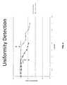
- FIG. 4illustrates an example graph of reflected power as a function of the position of the energy conducting element relative to the eye when the energy conducting element is positioned according to aspects of the present invention.
- FIG. 5illustrates an example graph of forward power as a function of time, showing how forward power changes when coolant pulses are delivered according to aspects of the present invention.
- FIG. 6illustrates an example graph of reflected power as a function of time, corresponding to the results illustrated in FIG. 5 , showing how reflected power changes when coolant pulses are delivered according to aspects of the present invention.
- FIG. 7Aillustrates a block diagram of a tuning element according to aspects of the present invention.
- FIG. 7Billustrates a perspective view of an embodiment of a tuning element according to aspects of the present invention.
- FIG. 7Cillustrates a cross-section of an embodiment of a tuning element according to aspects of the present invention.
- FIG. 8illustrates an example configuration for a system for measuring an electrical characteristic of an eye according to aspects of the present invention.
- FIG. 9illustrates a flowchart showing an example of a method of adjusting a tunable aspect of the applicator according to aspects of the present invention.
- FIG. 10illustrates a flowchart showing an example of a method of adjusting at least one tuning element according to aspects of the present invention.
- FIG. 11illustrates an embodiment of a method for monitoring proximity of the energy conducting element to an eye according to aspects of the present invention.
- FIG. 12illustrates an example graph of the efficiency of an applicator when changing the length of a single tuning stub according to aspects of the present invention.
- FIG. 13illustrates an example graph of the reflected power for different positions of the tuning stubs according to aspects of the present invention.
- FIG. 14illustrates an example graph of the reflected power as the electrodes advance towards the cornea according to aspects of the present invention.
- FIG. 15illustrates an example circuit with adjustable parameters that may be used for tuning purposes in lieu of or in addition to the fixed single or double tuning stub herein described according to aspects of the present invention.
- FIG. 16illustrates a cross-sectional view of an automated adjustment system for adjustably coupling an energy conducting element to an applicator housing according to aspects of the present invention.
- FIG. 17illustrates a cross-sectional view of an embodiment that permits an outer electrode and an inner electrode according to aspects of the present invention to be moved relative to each other.
- the embodiments described hereinrelate to a system and method for improving operation of an applicator that delivers heat-generating energy to an eye as a part of an eye therapy. For example, reflected power is measured to determine whether sufficient contact has been established between the applicator and the eye for accurate and precise delivery of energy to the eye. In addition, at least one of forward and reflected power is measured to monitor the application of coolant pulses that control the generation of heat in the eye when the applicator delivers energy to the eye.
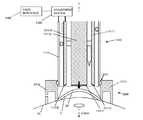
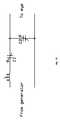
- FIG. 1illustrates an example system for applying heat to a cornea 2 of an eye 1 to cause reshaping of the cornea.
- FIG. 1shows an applicator 110 with an electrical energy conducting element 111 that is operably connected to an electrical energy source 120 , for example, via conventional conducting cables.
- the electrical energy conducting element 111extends from a proximal end 110 A to a distal end 110 B of the applicator 110 .
- the electrical energy conducting element 111conducts electrical energy from the source 120 to the distal end 110 B to apply heat energy to the cornea 2 , which is positioned at the distal end 110 B.
- the electrical energy source 120may include a microwave oscillator for generating microwave energy.
- the oscillatormay operate at a microwave frequency range of 400 MHz to 3000 MHz, and more specifically at a frequency of around 915 MHz or 2450 MHz which has been safely used in other applications.
- microwavecorresponds to a frequency range from about 10 MHz to about 10 GHz.
- the electrical energy conducting element 111may include two microwave conductors 111 A and 111 B, which extend from the proximal end 110 A to the distal end 110 B of the applicator 110 .
- the conductor 111 Amay be a substantially cylindrical outer conductor
- the conductor 111 Bmay be a substantially cylindrical inner conductor that extends through an inner passage extending through the conductor 111 A.
- the conductor 111 Ahas a substantially tubular shape.
- the inner and the outer conductors 111 A and 111 Bmay be formed, for example, of aluminum, stainless steel, brass, copper, other metals, coated metals, metal-coated plastic, or any other suitable conductive material.
- a substantially annular gap 111 C of a selected distanceis defined between the conductors 111 A and 111 B.
- the annular gap 111 Cextends from the proximal end 110 A to the distal end 110 B.
- a dielectric material 111 Dmay be used in portions of the annular gap 111 C to separate the conductors 111 A and 111 B.
- the distance of the annular gap 111 C between conductors 111 A and 111 Bdetermines the penetration depth of microwave energy into the cornea 2 according to established microwave field theory.
- the microwave conducting element 111receives, at the proximal end 110 A, the electrical energy generated by the electrical energy source 120 , and directs microwave energy to the distal end 111 B, where the cornea 2 is positioned.
- the outer diameter of the inner conductor 111 Bis preferably larger than the pupil.
- the outer diameter of the inner conductor 111 Bmay be selected to achieve an appropriate change in corneal shape, i.e. keratometry, induced by the exposure to microwave energy.
- the inner diameter of the outer conductor 111 Amay be selected to achieve a desired gap between the conductors 111 A and 111 B.
- the outer diameter of the inner conductor 111 Branges from about 2 mm to about 10 mm while the inner diameter of the outer conductor 111 A ranges from about 2.1 mm to about 12 mm.
- the annular gap 111 Cmay be sufficiently small, e.g., in a range of about 0.1 mm to about 2.0 mm, to minimize exposure of the endothelial layer of the cornea (posterior surface) to elevated temperatures during the application of heat by the applicator 110 .
- a controller 140may be employed to selectively apply the energy any number of times according to any predetermined or calculated sequence.
- the heatmay be applied for any length of time.
- the magnitude of heat being appliedmay also be varied. Adjusting such parameters for the application of heat determines the extent of changes that are brought about within the cornea 2 .
- the systemattempts to limit the changes in the cornea 2 to an appropriate amount of shrinkage of collagen fibrils in a selected region.
- the microwave energymay be applied with low power (of the order of 40 W) and in long pulse lengths (of the order of one second).
- other systemsmay apply the microwave energy in short pulses.
- the microwave energymay be applied in pulses having a higher power in the range of 500 W to 3 KW and a pulse duration in the range of about 10 milliseconds to about one second.
- each of the conductors 111 A and 111 Bmay be covered with an electrical insulator to minimize the concentration of electrical current in the area of contact between the corneal surface (epithelium) 2 A and the conductors 111 A and 111 B.
- the conductors 111 A and 111 B, or at least a portion thereofmay be coated with a material that can function both as an electrical insulator as well as a thermal conductor.
- a dielectric layer 110 Dmay be employed along the distal end 111 B of the applicator 110 to protect the cornea 2 from electrical conduction current that would otherwise flow into the cornea 2 via conductors 111 A and 111 B.
- the dielectric layer 110 Dis positioned between the conductors 111 A and 111 B and the cornea 2 .
- the dielectric layer 110 Dmay be sufficiently thin to minimize interference with microwave emissions and thick enough to prevent superficial deposition of electrical energy by flow of conduction current.
- the dielectric layer 110 Dmay be a biocompatible material deposited to a thickness of about 0.002 inches.
- an interposing layersuch as the dielectric layer 110 D, may be employed between the conductors 111 A and 111 B and the cornea 2 as long as the interposing layer does not substantially interfere with the strength and penetration of the microwave radiation field in the cornea 2 and does not prevent sufficient penetration of the microwave field and generation of a desired heating pattern in the cornea 2 .
- the dielectric materialmay be elastic, such as polyurethane and silastic, or nonelastic, such as Teflon® and polyimides.
- the dielectric materialmay have a fixed dielectric constant or varying dielectric constant by mixing materials or doping the sheet, the variable dielectric being spatially distributed so that it may affect the microwave hearing pattern in a customized way.
- the thermal conductivity of the materialmay have fixed thermal properties (thermal conductivity or specific heat), or may also vary spatially, through mixing of materials or doping, and thus provide a means to alter the heating pattern in a prescribed manner.
- Another approach for spatially changing the heating patternis to make the dielectric sheet material of variable thickness. The thicker region will heat less than the thinner region and provides a further means of spatial distribution of microwave heating.
- the distal end 110 B of the applicator 110 as shown in FIG. 1is positioned on or near the corneal surface 2 A.
- the applicator 110makes direct contact with the corneal surface 2 A.
- such direct contactpositions the conductors 111 A and 111 B at the corneal surface 2 A (or substantially near the corneal surface 2 A if there is a thin interposing layer between the conductors 111 A and 111 B and the corneal surface 2 A). Accordingly, direct contact helps ensure that the pattern of microwave heating in the corneal tissue has substantially the same shape and dimension as the gap 111 C between the two microwave conductors 111 A and 111 B.
- the energy conducting element 111includes a contact surface 111 G that comes into direct contact with the corneal surface 2 A.
- the outer conductor 111 Amay achieve sufficient contact with the eye 1 while the inner electrode 111 B does not have sufficient contact.
- the application of energy to the cornea 2depends in part on the position of the contact surface 111 G relative to the corneal surface 2 A.
- embodimentsensure that the contact surface 111 G, or portions thereof, are positioned to make contact with the corneal surface 2 A.
- the relationship between the energy conducting element 111 and the cornea 2is more definite and the resulting delivery of energy is more predictable and accurate.
- safetyis enhanced when the applicator 111 is in direct contact with the corneal surface 2 A and energy is transferred primarily to the system with good contact. Accordingly, it is preferable not to deliver energy via the energy conducting element 111 unless there is sufficient contact.
- sufficient contactis determined by causing an observable amount of flattening, or applanation, of the cornea.
- the applanationprovides a constant and uniform pressure against the corneal surface 2 A.
- the applicator 110can position the energy conducting element 111 against the corneal surface 2 A so that the contact surface 111 G flattens the cornea 2 .
- the contact surface 111 G, or portions thereof, in contact with the corneal surface 2 Aare shown to be substantially flat in FIG. 1 , it is understood that the contact surface 111 G may be shaped, e.g. contoured, in other ways to cause the desired contact.
- the applanation described hereinadds precision and accuracy to the eye therapy procedure, particularly by improving electrical and thermal contact between the contact surface 111 G and the corneal surface 2 A.
- the applicator 110may also include a micro-controlled coolant delivery system 112 .
- the micro-controlled coolant delivery system 112is in fluid communication with a coolant supply (not shown) and pulses of coolant, or cryogen, from the coolant supply may be applied to the corneal surface 2 A before, during, and/or after energy is applied to the cornea 2 with the electrical energy source 120 and the electrical energy conducting element 111 .
- the applicator 110may be employed to apply coolant to selectively cool the surface 2 A of the cornea 2 positioned at the distal end 110 B.
- the coolant delivery element 112may have a nozzle structure 112 A with an opening 112 B directed toward the distal end 110 B.
- FIG. 1may illustrate one nozzle structure 112 A
- coolant delivery system 112may include more than one nozzle structure 112 A arranged, for example, circumferentially within the annular gap 111 C.
- FIG. 1may illustrate the nozzle structure 112 A, other embodiments may employ other types of outlets or ports for delivering coolant to the surface 2 A or other areas of the eye 1 .
- the applicator 110may define a substantially enclosed assembly at the distal end 110 B, which is placed in contact with the corneal surface 2 A. As shown in FIG. 1 , this enclosed assembly may house the energy conducting element 111 and the coolant delivery element 112 .
- the dielectric layer 110 Dmay provide a membrane-like layer substantially enclosing the distal end 110 B of the applicator 110 . In this case, the coolant delivery system 112 applies coolant to the membrane, rather than directly to the eye 1 .
- the controller 140may also be operably connected to the coolant delivery element 112 as well as the energy source 120 . As such, the controller 140 may be employed to determine the amount and timing of coolant delivered from the coolant delivery element 112 toward the corneal surface 2 A at the distal end 110 B. The controller 140 may be employed to selectively apply the heat and the coolant any number of times according to a predetermined or calculated sequence. For instance, the coolant may be applied to the corneal surface 2 A before, during, or after the application of heat to the cornea 2 , or any combination thereof.
- the coolant delivery element 112may employ a solenoid valve in combination with the delivery nozzle 112 A.
- a solenoid valveis an electromechanical valve for use with liquid or gas controlled by applying or stopping an electrical current through a coil of wire, thus changing the state of the valve.
- the controller 140may electronically control the actuation of the solenoid valve to deliver the coolant through the delivery nozzle 112 A to the corneal surface 2 A.
- other embodimentsmay employ other types of actuators or alternative techniques for delivering coolant through the delivery nozzle 112 A in place of a solenoid valve.
- the controller 140may be used to actuate the application of micro-controlled pulses of coolant to the corneal surface 2 A before the application of heat to the cornea 2 .
- a pulse, or a spurt, of coolantis applied to the corneal surface 2 A for a predetermined short period of time so that the cooling remains generally localized at the corneal surface 2 A while the temperature of deeper corneal collagen fibers 2 B remains substantially unchanged.
- the pulseis on the order of milliseconds and is less than 100 milliseconds.
- the delivery of the coolant to the corneal surfaceis controlled by the controller 140 and may be less than 1 millisecond.
- the time between the application of the coolant and the application of the heatis also controlled by the controller 140 and may also be less than 1 millisecond.
- the coolant pulsegenerally covers an area of the corneal surface 2 A that corresponds with the application of heat to the cornea 2 .
- the shape, size and disposition of the cooled regionmay be varied according to the application.
- localized delivery of coolant to the corneal surface 2 A before the application of heat to the cornea 2minimizes the resulting temperature at the corneal surface 2 A when the heat is applied, thereby minimizing any heat-induced injury to the corneal surface 2 A.
- the coolantreduces the temperature of the corneal surface 2 A, so that the maximum surface temperature achieved at the corneal surface 2 A during or immediately after heat exposure is also reduced by a similar magnitude when compared to a case where no coolant is applied prior to heat exposure.
- the temperature at the corneal surface 2 Arises during or immediately after heat exposure with persistent surface heating resulting from a slow dissipation of heat trapped near the surface-air interface.
- a delayed thermal wavemay arrive at the corneal surface 2 A after exposure as the heat generated in the corneal areas 2 B below the surface 2 A diffuses toward the cooled surface 2 A.
- the heat transfer from the corneal surface 2 A to the surrounding airis likely to be insignificant, because air is an excellent thermal insulator.
- heat diffusing away from the areas 2 B beneath the corneal surface 2 Abuilds up near the corneal surface 2 A and produces an elevated surface temperature that may persist after the application of heat.
- the heat that builds up near the corneal surface 2 Amay eventually dissipate through thermal diffusion and cooling via blood perfusion, such dissipation may take several seconds.
- embodiments ofmay employ not only a pulse of coolant immediately prior to heat exposure, but also one or more pulses of coolant thereafter. Accordingly, in further operation of the embodiment of FIG. 1 , the controller 140 may also be used to apply micro-controlled pulses of coolant during or after the applicator 110 applies heat to the cornea 2 , or any combination thereof. This application of coolant rapidly removes heat which diffuses from the mid-depth corneal region 2 B to the corneal surface 2 A.
- the coolant delivery element 12delivers the pulse of coolant to the corneal surface 2 A
- the coolant on the corneal surface 2 Adraws heat from the surface 2 A, causing the coolant to evaporate.
- coolant applied to the surface 2 Acreates a heat sink at the surface 2 A, resulting in the removal of heat before, during, and after the application of heat to the cornea 2 .
- the heat sinkpersists for as long as the liquid cryogen remains on the surface 2 A.
- the heat sinkcan rapidly remove the trapped heat at the surface 2 A without cooling the collagen fibers in the region 2 B.
- a factor in drawing heat out of the cornea 2is the temperature gradient that is established near the surface 2 A. The steeper the gradient, the faster a given quantity of heat is withdrawn.
- the application of the coolantattempts to produce a large surface temperature drop as quickly as possible.
- the amount and duration of coolant applied to the corneal surface 2 Aaffects the amount of heat that passes into and remains in the region underlying the corneal surface 2 A.
- controlling the amount and duration of the coolingprovides a way to control the depth of corneal heating, promoting sufficient heating of targeted collagen fibers in the mid-depth region 2 B while minimizing the application of heat to regions outside the targeted collagen fibers.
- dynamic cooling of the corneal surface 2 Amay be optimized by controlling: (1) the duration of the cooling pulse(s); (2) the duty cycle of multiple pulses; (3) the quantity of coolant deposited on the corneal surface 2 A so that the effect of evaporative cooling can be maximized; and (4) timing of dynamic cooling relative to heat application.
- a single pulse timingmay include applying a 80 ms heat pulse and a 40 ms cooling pulse at the beginning, middle, or end of the heating pulse.
- multiple cooling pulsesmay be applied according to a pattern of 10 ms ON and 10 ms OFF, with four of these pulses giving a total of 40 ms of cooling, but timed differently.
- the coolantmay be the cryogen tetrafluoroethane, C 2 H 2 F 4 , which has a boiling point of about ⁇ 26.5° C. and which is an environmentally compatible, nontoxic, nonflammable freon substitute.
- the cryogenic pulse released from the coolant delivery element 112may include droplets of the cryogen cooled by evaporation as well as mist formed by adiabatic expansion of vapor.
- the coolantmay be selected so that it provides one or more of the following: (1) sufficient adhesion to maintain good surface contact with the corneal surface 2 A; (2) a high thermal conductivity so the corneal surface 2 A may be cooled very rapidly prior to heat application; (3) a low boiling point to establish a large temperature gradient at the surface; (4) a high latent heat of vaporization to sustain evaporative cooling of the corneal surface 2 A; and (5) no adverse health or environmental effects.
- tetrafluoroethanemay satisfy the criteria above, it is understood that embodiments of the present invention are not limited to a particular cryogen and that other coolants, such as liquid nitrogen, argon, or the like, may be employed to achieve similar results.
- the coolantdoes not have to be a liquid, but in some embodiments, may have a gas form.
- the pulse of coolantmay be a pulse of cooling gas.
- the coolantmay be nitrogen (N 2 ) gas or carbon dioxide (CO 2 ) gas.
- the controller 140may be employed to selectively apply the heat and the coolant pulses any number of times according to any predetermined or calculated sequence.
- the heat and the pulses of coolantmay be applied for any length of time.
- the magnitude of heat being appliedmay also be varied. Adjusting such parameters for the application of heat and pulses of coolant determines the extent of changes that are brought about within the cornea 2 .
- embodiments of the present inventionattempt to limit the changes in the cornea 2 to an appropriate amount of shrinkage of selected collagen fibers.
- the microwave energymay be applied with low power (of the order of 40 W) and in long pulse lengths (of the order of one second).
- microwave energymay be applied in short pulses.
- the microwave energymay be applied in pulses having a higher power in the range of 300 W to 3 kW and a pulse duration in the range of about 2 milliseconds to about one second.
- a first pulse of coolantis delivered to reduce the temperature of the corneal surface 2 A; a high power pulse of microwave energy is then applied to generate heat within selected areas of collagen fibers in a mid-depth region 2 B; and a second pulse of coolant is delivered in sequence to end further heating effect and “set” the corneal changes that are caused by the energy pulse.
- the application of energy pulses and coolant pulses in this manneradvantageously reduces the amount to heat diffusion that occurs and minimizes the unwanted impact of heating and resulting healing processes on other eye structures, such as the corneal endothelium.
- this techniquepromotes more permanent and stable change of the shape of the cornea 2 produced by the heat.
- the application of high powered energy in short pulseshas been described with respect to the delivery of microwave energy, a similar technique may be applied with other types of energy, such as optical energy or electrical energy with radio frequency (RF) wavelengths described further below.
- RFradio frequency
- FIG. 1The system of FIG. 1 is provided for illustrative purposes only, and other systems may be employed to apply energy to generate heat and reshape the cornea.
- Other systemsare described, for example, in U.S. patent application Ser. No. 12/208,963, filed Sep. 11, 2008, which is a continuation-in-part application of U.S. patent application Ser. No. 11/898,189, filed on Sep. 10, 2007, the contents of these applications being entirely incorporated herein by reference.
- FIGS. 2A-Dillustrate an example of the effect of applying heat to corneal tissue with a system for applying heat, such as the system illustrated in FIG. 1 .
- FIGS. 2A and 2Billustrate high resolution images of cornea 2 after heat has been applied.
- a lesion 4extends from the corneal surface 2 A to a mid-depth region 2 B in the corneal stroma 2 C.
- the lesion 4is the result of changes in corneal structure induced by the application of heat as described above. These changes in structure result in an overall reshaping of the cornea 2 . It is noted that the application of heat, however, has not resulted in any heat-related damage to the corneal tissue.
- FIGS. 2A and 2Billustrate histology images in which the tissue shown in FIGS. 2A and 2B has been stained to highlight the structural changes induced by the heat.
- FIGS. 2C and 2Dillustrate histology images in which the tissue shown in FIGS. 2A and 2B has been stained to highlight the structural changes induced by the heat.
- the difference between the structure of collagen fibrils in the mid-depth region 2 B where heat has penetrated and the structure of collagen fibrils outside the region 2 Bis clearly visible.
- the collagen fibrils outside the region 2 Bremain generally unaffected by the application of heat, while the collagen fibrils inside the region 2 B have been rearranged and formed new bonds to create completely different structures.
- unlike processes, like orthokeratologywhich compress areas of the cornea to reshape the cornea via mechanical deformation, the collagen fibrils in the region 2 B are in an entirely new state.
- FIG. 3illustrates an example configuration for a system 200 that may employ the electrical energy conducting element 111 described previously.
- the electrical energy conducting element 111may directly contact the eye 1 with the contact surface 111 G.
- the contact surface 111 Gmay be defined by a membrane-like dielectric layer substantially enclosing the distal end 110 B of the applicator 110 .
- the coolant delivery system 112applies coolant to the membrane, rather than directly to the eye 1 .
- a microwave amplifier/source 120 ′which may be controlled by the controller described previously, sends microwave energy to an eye 1 via the electrical energy conducting element 111 which is placed into contact with the eye 1 .
- the microwavesare delivered through the energy conducting element 111 , some microwaves are reflected from the distal end 110 B of the energy conducting element 111 , and these reflected microwaves have a reflected power.
- the reflected powergenerally decreases with increased contact between the energy conducting element 111 and the eye 1 .
- the net forward power actually delivered to the eye 1is approximately equal to the difference between the forward power and the reflected power.
- a dual directional coupler 122may be employed to sample the microwaves and determine the forward power and the reflected power to provide outputs 123 and 124 , respectively.
- the outputs 123 and 124may actually provide levels that are proportional to the initial forward power and the reflected power, respectively.
- the dual directional coupler 122may sense the reflected power as a 1/1000 sample of the actual reflected power.
- the system 200 of FIG. 3determines whether the desired contact between the energy conducting element 111 and the eye 1 has been achieved so that the resulting delivery of energy may be applied more predictably and accurately.
- the dual directional coupler 122is employed to determine the reflected power which indicates the level of contact between the energy conducting element 111 and the eye 1 . If the reflected power indicates insufficient contact, the system 200 does not further deliver microwaves, for example, through the energy conducting element 111 .
- system 200may be particularly advantageous, because when the applicator 110 is positioned over the eye 1 during operation, the clinician's view of the contact between the energy conducting element 111 and the eye 1 may be obstructed by the applicator 110 itself. Thus, the system 200 allows the clinician to determine whether sufficient contact has been established without requiring visual confirmation. During operation, the clinician monitors the change in reflected power as the applicator 110 is positioned. The change in reflected power indicates the change in contact and applanation and thus allows the clinician to accurately determine the position of the energy conducting element 111 .
- FIG. 3The system of FIG. 3 is provided for illustrative purposes only. Other systems are described, for example, in U.S. Provisional Patent Application No. 61/098,489, filed Sep. 19, 2008, the contents of which is entirely incorporated herein by reference. As described in U.S. Provisional Patent Application No. 61/098,489, a monitoring system may be employed to monitor both the power delivered to, and reflected from, the eye 1 . As described therein, the system may be utilized to extract information on the position of the energy conducting element 111 relative to the eye 1 or on the operation of the cooling delivery system 112 . Aspects of the operation of the cooling delivery system 112 are described, for example for example, in U.S. patent application Ser. No. 12/208,963, filed Sep. 11, 2008, which is a continuation-in-part application of U.S. patent application Ser. No. 11/898,189, filed on Sep. 10, 2007, the contents of these applications already being entirely incorporated herein by reference.
- the x-axisrepresents the number of turns that lowers the energy conducting element 111 along screw-like threads into position over the eye 1 . The number of turns increases until the energy conducting element 111 moves into greater contact with the eye 1 .
- the y-axisis a measure of reflected power in units of dBm (power ratio in decibels (dB) of the measured power referenced to one milliwatt (mW)). As discussed previously, a lower reflected power indicates better contact with the eye 1 .
- the energy conducting element 111included outer and inner electrodes with a thin interposing membrane, i.e., polyurethane with 50 micron thickness, providing a contact surface 111 G with the eye.
- a thin interposing membranei.e., polyurethane with 50 micron thickness
- one curverepresents the reflected power for an energy conducting element 111 that is centered over the eye
- the other curverepresents the reflected power for an energy conducting element 111 that is 1 mm from the centered position.
- the curvesgenerally showed no change, remaining at approximately 2 dBm.
- the points A and B shown on the graphindicate where contact was achieved for the centered energy conducting element 111 and off-center energy conducting element 111 , respectively.
- the energy conducting element 111was lowered into position to applanate onto the eye 1 .
- the corresponding reflected powerdecreased. Accordingly, the results shown in FIG. 4 demonstrate that the reflected power can be measured to determine whether sufficient contact between the energy conducting element 111 and the eye 1 has been achieved to enable the desired transfer of energy to the eye 1 .
- the reflected powermay be measured as the energy conducting element 111 is moved into further contact with the eye 1 , and the decrease in the reflected power corresponding to the increase in contact may be monitored to determine when the desired amount of applanation has been achieved.
- the embodiments described aboveinvolve systems in which the reflected power decreases as the amount of contact increases, the reflected power in other embodiments increases as the amount of contact increases. It is to be understood that the tuning or calibration of the system determines whether the reflected power decreases or increases as the amount of contact increases. In general, a change in the amount of contact between the applicator and the eye is indicated by a change in the reflected power.
- coolant pulsesmay also be applied to the eye to preserve the epithelium or surface of the eye during thermal treatment with microwaves.
- a pulse train with 5 ms ON and 5 ms OFFmay be utilized and repeated 3-20 times.
- Monitoring the effect of the coolant pulsesis important, because the coolant application helps to protect the surface of the eye as described previously.
- Ordinary flow metersmay not be sufficiently able to detect and monitor short pulses of coolant on the order of approximately 5 ms to 50 ms as such pulses generally deliver small volumes of coolant, e.g., on the order of microliters.
- the system 200 shown in FIG. 3includes a dual directional coupler 122 that may be employed to sample the microwaves and determine the forward power and the reflected power to provide outputs 123 and 124 , respectively.
- a temperature sensormay be used to detect coolant pulses.
- FIG. 5illustrates an example graph of forward power as a function of time, which shows how forward power changes when coolant pulses are delivered.
- FIG. 5illustrates five pulses of cooling and five no-cooling periods with microwave power as a single long pulse over the entire period.
- the forward powerdecreases to approximately 194 W.
- the forward powerincreases to approximately to 202 W.
- the calibration or tuning of the systemdetermines whether the reflected power increases or decreases.
- FIG. 6illustrates an example graph of reflected power as a function of time for the same pulse train, which shows how reflected power changes when coolant pulses are delivered.
- the coolantis delivered in a 10 ms pulse, for example, the reflected power increases to 16 W. In between pulses, the power drops to 0.5 W.
- monitoring the forward and/or reflected power over timeprovides a non-invasive means of monitoring the application of cooling pulses applied to the eye.
- the shape of the curveindicates the amount of coolant applied and the amount of rewarming between applications of coolant.
- Long cooling pulsesmay also be detected by monitoring the forward and/or reflected power. For example, if a 50-100 ms pulse of microwaves is applied, the system may detect a cooling pulse is applied for the whole microwave pulse duration or any part thereof.
- FIG. 7Aillustrates a block diagram of a tuning element 150 .
- the tuning element 150includes conductive components incorporating at least one adjustable aspect such that a modification of the adjustable aspect results in a change in either the inductance, or the capacitance, or both of an electrical circuit connected to the tuning element 150 .
- the tuning element 150enables the circuit to be tuned to a particular impedance value by making changes to the at least one adjustable aspect of the tuning element 150 .
- the tuning element 150may include an inner conductor 150 B and an outer conductor 150 A electrically connected to a short connector 150 E.
- the adjustable aspectmay be embodied as a short connector 150 E that may be adjustably electrically connected between the inner conductor 150 B and the outer conductor 150 A.
- the short connector 150 Emay be mechanically manipulated so as to move along a path substantially between the outer conductor 150 A and the inner conductor 150 B. While the short connector 150 E moves along the path between the outer conductor 150 A and the inner conductor 150 B it may maintain a continuous electrical connection between the outer conductor 150 A and the inner conductor 150 B or it may establish only an intermittent electrical connection between the outer conductor 150 A and the inner conductor 150 B.
- the short connector 150 Emay establish no electrical connection at all between the outer conductor 150 A and the inner conductor 150 B while moving along a path enclosed by the outer conductor 150 A and the inner conductor 150 B only to effect an electrical connection between the outer conductor 150 A and the inner conductor 150 B once mechanical manipulation of the short connector 150 E is halted.
- the short connector 150 Emay be embodied as an elastic or deformable conductive material which has an electrical connection on the outer conductor 150 A that is fixed in position, and which is connected to the inner conductor 150 B with a connection that may be adjusted in position.
- open stubs of varying lengthsmay be used in the place of or in addition to shorted stubs.
- any circuit with adjustable parameters that change the inductance and/or capacitance of the systemmay be used for tuning purposes in lieu of or in addition to the fixed single or double tuning stub herein described.
- An example of such a circuitis shown in FIG. 15 .
- the software-controlled tuning adjustmentscan be made with motorized variable capacitors, a binary capacitor cascade and solid state switches, and the like.
- the short connector 150 E, the inner conductor 150 B, and the outer conductor 150 Aare each composed, at least in part, of suitable electrically conducting materials.
- the inner conductor 150 B, the outer conductor 150 A, and the short connector 150 Emay be formed, for example, of aluminum, stainless steel, brass, copper, silver, other metals, metal-coated plastic, or any other suitable conductive material.
- the materials used to construct the inner conductor 150 B and the outer conductor 150 Amay be chosen, for example, in order to effect a characteristic impedance value for an electrical circuit connected to the outer conductor 150 A and the inner conductor 150 B.
- the dimensions of the outer conductor 150 A and the inner conductor 150 Bmay also be chosen in order to effect a characteristic impedance value for an electrical circuit connected to the outer conductor 150 A and the inner conductor 150 B.
- the tuning element 150is embodied as having substantial cylindrical symmetry such that both the outer conductor 150 A and the inner conductor 150 B are embodied as cylinders about a common axis of symmetry
- adjustments to the diameters of the inner conductor 150 B and the outer conductor 150 Amay be used to adjust the impedance of the tuning element 150 .
- the impedance of the tuning element 150may be adjusted to be 50 Ohms (50 ⁇ ).
- the tuning element 150further includes an electric motor 150 F which is mechanically engaged to the short connector 150 E via a mechanical connection 150 G.
- the mechanical connection 150 Gmay incorporate belts, cogs, wheels, pulleys, screws, levers, devices applying torque, or any other conventional means of achieving movement of the short connector 150 G.
- the operation of the electric motor 150 Fis mediated by automated computer control, which may be achieved using the controller 140 .
- the controller 140may send a command to the electric motor 150 F to move the short connector.
- the commandmay be sent and received via an electrical connection or via a wireless signal or any other conventional method of sending digital or analog information across distances.
- the electric motor 150 Fmay then engage the mechanical connection 150 G to move the short connector 150 E along a path substantially enclosed by the outer conductor 150 A and the inner conductor 150 B.
- FIG. 7Billustrates a perspective view of an embodiment of a tuning element 150 , which shows a cut-away sectional view. As shown in FIG. 7B the tuning element 150 terminates at a proximal end 150 H.
- the inner conductor 150 Bmay define a cylinder, which may be either solid or hollow, while the outer conductor.
- the area between the inner conductor 150 B and the outer conductor 150 Acreates an annular gap 150 C.
- the annular gap 150 Cmay be embodied as an empty space, or it may be filled with a suitable dielectric material, which may be used, at least, to achieve a substantially constant spacing between the inner conductor 150 B and the outer conductor 150 A.
- the dielectric materialmay be chosen in order to effect a desired impedance of a circuit containing the inner conductor 150 B and the outer conductor 150 A.
- the inner conductor 150 B and the outer conductor 150 Aare both constructed to have cylindrical symmetry about a central axis, then the annular gap 150 C has cylindrical symmetry about the same axis.
- a short connector 150 Ewhich provides an electrical connection between the inner conductor 150 B and the outer conductor 150 A.
- the short connector 150 Emay be configured so as to move in a direction parallel to the axis of cylindrical symmetry of the inner conductor 150 B and outer conductor 150 A, with one such direction indicated by the arrow in FIG. 7B .
- the region of the tuning element 150 between the proximal end 150 H and the point of connection between the inner conductor 150 B and the short connector 150 Edefines the length of a waveguide that is open on the proximal end 150 H.
- an example embodiment of the tuning element 150is a system for incorporating a waveguide of adjustable length into a circuit including the inner conductor 150 B and the outer conductor 150 A, wherein the length of the waveguide is adjustable upon command of the controller 140 that may cause the electric motor 150 F to engage the mechanical connection 150 G to mechanically manipulate the short connector 150 E and thereby effect a change in the length of the waveguide between the proximal end 150 H and the point of intersection between the inner conductor 150 B and the short connector 150 E.
- the length of the waveguideis adjustable upon command of the controller 140 that may cause the electric motor 150 F to engage the mechanical connection 150 G to mechanically manipulate the short connector 150 E and thereby effect a change in the length of the waveguide between the proximal end 150 H and the point of intersection between the inner conductor 150 B and the short connector 150 E.
- the short connector 150 Eis depicted capable of moving in a direction transverse to its dominant length, but the short connector 150 may be oriented in any manner while it is mechanically manipulated so as to effect a change in length of the waveguide located between the proximal end 150 H and the point of intersection between the inner conductor 150 B and the short connector 150 E.
- FIG. 7Cillustrates a side view cross section of an embodiment of a tuning element 150 .
- the embodiment of the tuning element 150includes an inner conductor 150 B, an outer conductor 150 A, a short connector 150 E which may be mechanically manipulated in a direction substantially parallel to the axis of symmetry of the inner conductor 150 B and the outer conductor 150 A, as shown by the arrows in the FIG. 7C .
- FIG. 4Cfurther illustrates a proximal end 150 H such that the distance between the proximal end 150 H and the point of intersection between the inner conductor 150 B and the short connector 150 E is defined by
- the example embodiments of the tuning element 150 shown in FIGS. 7A , 7 B, and 7 Care shown for example purposes only.
- the tuning element 150includes conductive components incorporating at least one adjustable aspect such that a modification of the adjustable aspect results in a change in either the inductance, or the capacitance, or both of an electrical circuit in connection with the tuning element 150 .
- the tuning element 150enables the circuit to be tuned to a particular impedance value by making changes to the at least one adjustable aspect of the tuning element 150 .
- tuning element 150is shown and described in one embodiment in FIGS. 7A , 7 B, and 7 C, it is contemplated that the tuning element 150 is not required for use in all embodiments of the invention.
- the applicatorcan be carefully tuned to an eye once, and will not have to be tuned again for subsequent uses.
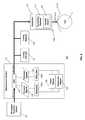
- FIG. 8illustrates a system 500 for measuring an electrical characteristic of an eye 1 .
- An embodiment of the system 500may utilize a measurement system 127 to measure aspects of a reflection coefficient.
- the reflection coefficientis the reflected voltage divided by the forward voltage, where the voltage is a complex number that is a function of magnitude and phase.
- An example embodiment of the measurement system 127may incorporate a phase sensor 128 or a magnitude sensor or both and includes a dual directional coupler (DDC) 122 , which provides outputs to split signals into forward signals 127 and reflected signals 126 .
- DDCdual directional coupler
- the forward signal output 125 of the DDC 122may be electrically connected to an attenuator 125 A, and the output of the attenuator 125 A may then be electrically connected to a phase sensor 128 , a magnitude sensor 129 , or to both.
- the reflected signal output 126may be electrically connected to an attenuator 126 A, and the output of the attenuator 126 A may then be electrically connected to a phase sensor 128 , a magnitude sensor 129 , or to both.
- An embodiment of the system 500may also include a plurality of tuning elements.
- the embodiment of the system 500 depicted in FIG. 8includes a first tuning element 152 and a second tuning element 153 connected in parallel to the output of the measurement system 127 at predetermined locations.
- the tuning elements 152 and 153may each include conductive components incorporating at least one adjustable aspect such that a modification of the adjustable aspect results in a change in either the inductance, or the capacitance, or both of an electrical circuit in connection with the tuning elements 152 and 153 .
- the tuning elements 152 and 153enables the circuit to be tuned to a particular impedance value by making changes to the at least one adjustable aspect of the tuning elements 152 and 153 .
- the tuning elements 152 and 153may substantially incorporate many of the features of the tuning element 150 described above and illustrated in FIGS. 7A , 7 B, 7 C.
- An embodiment of the system 500 for measuring an electrical characteristic of an eye 1may incorporate an energy source 120 , which may include an oscillator for generating energy at microwave frequencies and an output which is electrically connected to an input of the DDC 122 .
- An output of the DDC 122may then be connected to an applicator 110 .
- the applicator 110may include a conducting element 111 for application of energy at its proximal end 110 B to an eye 1 at a contact surface 111 G. Aspects of the applicator 110 may incorporate features of the applicator 110 shown in FIG. 1 .
- the conducting elementmay include a tunable aspect 151 .
- the tunable aspect 151may be embodied as an adjustable conducting element between the outer conductor 110 A and the inner conductor 110 B so as to adjust the output impedance of the applicator 110 .
- the measurement system 127is electrically connected between the energy source 120 and the applicator 110 . Between the measurement system 127 and the applicator 110 a plurality of tuning elements connected in parallel at predetermined locations. For example a first tuning element 152 and a second tuning element 153 may be connected in parallel between the measurement system 127 and the applicator 110 .
- energymay be generated in the energy source 120 at a microwave frequency.
- the microwavesmay then be conducted to an applicator 110 after passing through a measurement system 127 , which incorporates a DDC 122 and a phase sensor 128 or a magnitude sensor 129 or both.
- a measurement system 127which incorporates a DDC 122 and a phase sensor 128 or a magnitude sensor 129 or both.
- some microwave energyis transmitted into the eye 1 , while some additional microwave energy is reflected at the junction to travel back through the conducting element 111 toward the measurement system 127 .
- the sum of the microwave energy reflected, the microwave energy transmitted, and all the microwave energy lost due to line losses and radiation leakswill substantially equal the amount of microwave energy generated in the energy source 120 .
- the forward signal output 125may then be passed through an attenuator 125 A, which may reduce the amplitude of the forward microwave signal by a predetermined amount.
- the reflected signal output 126may then be passed through an attenuator 126 A, which may reduce the amplitude of the reflected microwave signal by a predetermined amount.
- the reflected and forward microwave signalsmay then each be provided to either a phase sensor 128 , or a magnitude sensor 129 , or both in order to determine the amount of microwave energy reflected compared to the amount of microwave energy generated.
- this informationmay also allow for the calculation of the impedance value of the eye 1 when the impedance value of the system 500 is known.
- adjusting the impedance of the applicator 110may be advantageous, for example, in order to achieve a desired efficiency of energy absorption to the eye 1 by the applicator 110 .
- a desired efficiency of energy absorption to the eye 1 by the applicator 110when energy is conducted or transmitted across a surface boundary, i.e. across a junction wherein a first portion of the junction has a first impedance value and a second portion of the junction has a different impedance value, some energy is transmitted through the junction and some is reflected. Energy is most efficiently transmitted when the two impedances are as near as possible to identical.
- an applicator 110which includes a tunable aspect 151 in the conducting element 111 so as to adjust the impedance value of the applicator 110 may allow for adjustment of the impedance of value of the applicator 110 so as to correspond in a desirable manner with the impedance value of the eye 1 .
- the tunable aspect 151 and/or the first tuning element 152 and/or the second tuning element 153may not include an adjustable conducting element between the outer conductor 110 A and the inner conductor 110 B, but may be embodied as a conducting element providing an electrical connection between the outer conductor 110 A and the inner conductor 110 B which may be fixed in place in a removable or permanent manner so as to allow for the placement of the tunable aspect 151 and/or the first tuning element 152 and/or the second tuning element 153 to be determined according to an electrical characteristic of the system 500 .
- FIG. 9illustrates a flowchart showing an example of a method 600 of adjusting a tunable aspect 151 of the applicator 110 so as to achieve a desired transmission efficiency between the conducting element 111 and the eye 1 .
- the method 600 of adjusting a tunable aspect 151may be exercised using, for example, a system 500 for measuring an electrical characteristic of an eye 1 .
- An embodiment of the method 600 of adjusting a tunable aspect 151includes a first step 602 where a first amount of energy is applied to the eye 1 .
- the method 600may further include a second step 604 wherein a measurement of a magnitude of phase change of a reflection coefficient may be measured and then retained for reference.
- the measurement accomplished in the second step 604may be accomplished with a measurement system 127 , such as that described in the system 500 appearing in FIG. 8 .
- the method 600may further include a third step 608 where at least one adjustable parameter of a tunable aspect 151 may be adjusted. In an example embodiment utilizing the system 500 for measuring an electrical characteristic of an eye 1 , the third step 608 may adjust the impedance value of the system 500 .
- the method 600may further include a fourth step 606 wherein an additional amount of energy is applied to the eye 1 .
- the method 600may further include a fifth step 610 wherein a subsequent magnitude or phase change of the reflection coefficient is measured and retained for reference.
- the method 600may further include a sixth step 612 wherein a determination is made as to whether an acceptable efficiency has been achieved. If it is determined in the sixth step 612 that an acceptable efficiency has been achieved then the method 600 ends. If, on the other hand, it is determined in step six 612 that an acceptable efficiency has not been achieved, then at least one parameter of the tunable aspect may be modified again in the third step 608 .
- the operation of the first step 602enables the measurement activity accomplished in the second step 604 .
- the third step 608is undertaken, which is followed by steps four 606 and five 610 , which are accomplished in a manner substantially similar to the completion of steps one 602 and two 604 .
- step six 612is undertaken and depending on the determination made in step six 612 , steps three through six, 608 , 606 , 610 , and 612 may be completed in a loop until a determination is made in step six 612 that an acceptable efficiency has been attained so as to end the method 600 .
- the determination in step six 612may be based on achieving a predetermined minimal impedance mismatch, which may be determined after sampling a range of values until a local or global minimum is identified in a value of a reflection coefficient as measured in the measurement system 127 , as shown, for example, in FIG. 8 .
- Estimating the location substantially equivalent to the local or global minimum value of the reflection coefficient with respect to the tunable aspect 151may be accomplished by comparing all of the collected values stored in operation of the iterative method 600 , or it may be based on a subset of those values.
- the determinationmay be made using a software program to fit a predetermined mathematical function to a curve of measured values of the reflection coefficient, such as the curve represented in FIG. 12 . As shown, FIG.
- the determination in step six 612may be based on achieving an acceptable impedance mismatch. That is, the efficiency may be deemed acceptably efficient so as to end the method 600 when the measurement system 127 measures an effective impedance mismatch below some predetermined threshold value. In another example embodiment of the method 600 , the determination in step six 612 may be deemed acceptably efficient so as to end the method 600 when the measurement system 127 measures an effective impedance within a certain threshold of upper and lower boundaries. Alternatively, an embodiment of the method 600 may incorporate a determination in step six 612 that is some combination of each of these.
- FIG. 10illustrates a flowchart showing an example of a method 700 of adjusting at least one tuning element so as to achieve an acceptable impedance mismatch.
- the method 700 of adjusting at least one tuning elementmay be exercised using, for example, a system 500 for measuring an electrical characteristic of an eye 1 and the at least one tuning element may be a first tuning element 152 or a plurality of tuning elements, such as the first tuning element 152 and second tuning element 153 shown in FIG. 8 connected in parallel in the system 500 .
- An embodiment of the method 700 of adjusting at least one tuning elementincludes a step one 702 where a first amount of energy is applied to the eye 1 .
- the method 700may further include a step two 704 wherein a measurement of a magnitude of phase change of a reflection coefficient may be measured and then retained for reference.
- the measurement accomplished in step two 704may be accomplished, for example, with a measurement system 127 , such as that described in the system 500 appearing in FIG. 8 .
- the method 700may further include a step three 708 where an adjustable parameter of at least one tuning element may be adjusted.
- the third step 708may adjust the impedance value of the system 500 by adjusting at least one adjustable parameters of at least one tuning element such as the tuning elements 152 and 153 .
- the method 700may further include a step four 706 wherein an additional amount of energy is applied to the eye 1 .
- the method 700may further include a step five 710 wherein a subsequent magnitude or phase change of the reflection coefficient is measured and retained for reference.
- the method 700may further include a step six 712 wherein a determination is made as to whether an acceptable impedance mismatch has been achieved. If it is determined in step six 712 that an acceptable efficiency has been achieved, then the method 700 ends. If, on the other hand, it is determined in step six 712 that an acceptable efficiency has not been achieved, then at least one parameter of the tunable aspect may be modified again by retuning to step three 708 .
- the operation of the first step 702enables the measurement activity accomplished in the second step 704 .
- the third step 708is undertaken, which is followed by steps four 706 and five 710 , which are accomplished in a manner substantially similar to the completion of steps one 702 and two 704 .
- step six 712is undertaken and depending on the determination made in step six 712 , steps three through six, 708 , 706 , 710 , and 712 may be completed in a loop until a determination is made in step six 712 that an acceptable impedance mismatch has been attained so as to end the method 700 .
- the determination in step six 712may be based on achieving an acceptable impedance mismatch. That is, the efficiency may be deemed acceptably efficient so as to end the method 700 when the measurement system 127 measures an effective impedance mismatch below some predetermined threshold value. When the determination in step six 712 is based on achieving an impedance mismatch of some threshold value, step five 710 may not retain subsequent values for future reference. In another example embodiment of the method 700 , the determination in step six 712 may be deemed acceptably efficient so as to end the method 700 when the measurement system 127 measures an effective impedance within a certain threshold of upper and lower boundaries. Alternatively, an embodiment of the method 700 may incorporate a determination in step six 712 that is some combination of each of these.
- FIG. 11illustrates an embodiment of a method 800 for monitoring proximity of the conducting element 111 as previously described to an eye 1 .
- the method 800may be exercised, for example, utilizing a system 500 for measuring an electrical characteristic of an eye 1 .
- the method 800includes a step one 802 , a step two 804 , a step three 805 , a step four 806 , a step five 808 , an optional step six 810 , and a final step seven 812 , which may provide for an iterative process to restart at step three 805 .
- an initial amount of energyis applied to an eye 1 in step one 802 .
- an initial magnitude or phase change of a reflection coefficientis measured and retained for later reference in step two 804 .
- an additional amount of energyis applied to the eye 1 in step three 805 .
- the application of energy to the eye 1 in step three 805allows for a subsequent measurement of a magnitude or phase change of the reflection coefficient in step four 806 .
- the measurement of the magnitude of phase change of a reflection coefficient in step two 804 and step four 806may be accomplished using a measurement system 127 .
- step five 808the subsequent value measured in step four 806 is compared with the initial value measured in step two 804 .
- corrective measuresmay be taken in step six 810 .
- the corrective measures taken in step six 810 in an embodiment utilizing the system 500 depicted in FIG. 8may include, for example, an modification in the duration of the pulse length of an application of energy through the conducting element 111 , an increase in the forward power generated in the energy source 120 so as to effect the transmission of a desired amount of microwave energy to the eye 1 for therapeutic treatment, and/or advancing the conducting element toward the eye.
- step eight 812the difference in the initial value measured in step 804 and the subsequent value measured in step four 806 are determined to exceed some predetermined threshold, then the method 800 may be terminated at step five 808 rather than advancing to step six 810 or step seven 812 . If the determination in step 808 finds to difference between the initial value measured in step two 804 and the subsequent value measured in step four 806 , then an additional determination is made in step seven 812 . Following the corrective measures taken in step 810 , an additional determination is made in step seven 812 . The determination made in step seven 812 is whether to continue advancing the energy conducting element 111 toward the eye.
- Advancementmay be halted if, for example, an individual using a system 500 for measuring electrical characteristics of an eye to apply energy to an eye indicates that advancement should be halted, for example, because acceptable proximity has been achieved.
- the determination to halt advancementmay then be indicated by some savable means in communication with, for example, a controller 140 , such that the information indicating advancement should be halted is retrievable by an automated process in step seven 812 .
- the methodis restarted with step three 805 .
- step seven 812may provide for a predetermined rest time before restarting the method at step three 805 in order to achieve a desired duty cycle of applying corrections in step 810 and monitoring the proximity, which is principally accomplished in step five 808 .
- FIG. 13illustrates a plot of the magnitude of the reflection coefficient,
- FIG. 14illustrates an example graph of the reflected power in dBm as the electrode 111 B is positioned at various distances from corneal surface 2 A.
- the system 500 depicted in FIG. 8can be used to sense proximity with the cornea. After the system 500 has been tuned to air or a similar reference, the electrode 111 B are lowered towards the corneal surface 2 A. As the electrode 111 B approaches the corneal surface 2 A, the reflected power changes from its original tuned to air value, as shown in FIG. 14 . By monitoring the reflected power, the system can determine the correct location of the electrode 111 B relative to the corneal surface 2 A. Choosing a certain feature of the curve of FIG. 14 and stopping electrode movement once it is sensed ensures correct position of the electrode 111 B independent of variations in eye geometry, and reproducible energy delivery.
- the amount of impedance of the corneamay be determined according to patient characteristics, including, but not limited to, age, gender, corneal thickness, and other similar factors that affect how corneal changes may be induced. Data relating to such factors and corresponding impedances may be compiled from a sample of past patients and reduced to a nomogram, look-up table, or the like. This compiled data may then serve as a guide for determining the impedance in future treatments.
- FIG. 16illustrates an exemplary movement of an energy conducting element 1111 toward a cornea 2 .
- adjusting the position of the energy conducting element 1111may be achieved manually, a more automated adjustment system 1300 , as shown in FIG. 16 , can be employed.
- the adjustment system 1300facilitates the accurate positioning of the energy conducting element 1111 against a corneal surface 2 A.
- an applicator 1100is guided into position within the passageway 1211 of the attachment element 1210 , and the adjustment system 1300 can be easily operated to move the distal surfaces 1111 E and 1111 F of the energy conducting element 1111 against the corneal surface 2 A.
- the adjustment system 1300may be further connected to a user interface system 1305 that accepts input from a user and correspondingly operates the adjustment system 1300 .
- the user interface system 1305may be a device with a keypad to receive input from a user.
- the keypadmay be part of a processing system, such as a conventional personal computer, with software to control the adjustment system 1300 .
- the user interface system 1305may be a device, such as a joystick, that receives instructions from the user through more mechanically oriented input.
- the adjustment system 1300moves the outer conductor 1111 A and the inner conductor 1111 B as a single element relative to a housing 1110 .
- the outer conductor 1111 A and the inner conductor 1111 Bmay be decoupled so that they can be moved relative to each other. Accordingly, with the housing 1110 fixed relative to the eye 2 (e.g., with a positioning system 1200 ), the contact between the outer conductor 1111 A and the corneal surface 2 A may be controlled separately from the contact between the inner conductor 1111 B and the corneal surface 2 A.
- FIG. 17illustrates an exemplary embodiment of the energy conducting element 1111 where the outer conductor 1111 A follows a movement A and the inner conductor 1111 B follows a movement B, where the movements A and B may be separately controlled.
- the energy conducting element 1111may be employed with an adjustment system 1300 A that moves the outer conductor 1111 A relative to the housing 1110 and an adjustment system 1300 B that moves the inner conductor 1111 B relative to the housing 1110 .
- the energy conducting element 1111 of FIG. 17allows the movement A to be different from the movement B, the movement A can also be substantially similar to the movement B.
Landscapes
- Health & Medical Sciences (AREA)
- Surgery (AREA)
- Life Sciences & Earth Sciences (AREA)
- Veterinary Medicine (AREA)
- Animal Behavior & Ethology (AREA)
- Nuclear Medicine, Radiotherapy & Molecular Imaging (AREA)
- Electromagnetism (AREA)
- Engineering & Computer Science (AREA)
- Biomedical Technology (AREA)
- Heart & Thoracic Surgery (AREA)
- Physics & Mathematics (AREA)
- Public Health (AREA)
- General Health & Medical Sciences (AREA)
- Otolaryngology (AREA)
- Molecular Biology (AREA)
- Medical Informatics (AREA)
- Ophthalmology & Optometry (AREA)
- Optics & Photonics (AREA)
- Vascular Medicine (AREA)
- Radiation-Therapy Devices (AREA)
- Surgical Instruments (AREA)
- Thermotherapy And Cooling Therapy Devices (AREA)
Abstract
Description
Claims (12)
Priority Applications (1)
| Application Number | Priority Date | Filing Date | Title |
|---|---|---|---|
| US12/617,554US8882757B2 (en) | 2008-11-11 | 2009-11-12 | Eye therapy system |
Applications Claiming Priority (2)
| Application Number | Priority Date | Filing Date | Title |
|---|---|---|---|
| US11339508P | 2008-11-11 | 2008-11-11 | |
| US12/617,554US8882757B2 (en) | 2008-11-11 | 2009-11-12 | Eye therapy system |
Publications (2)
| Publication Number | Publication Date |
|---|---|
| US20100185192A1 US20100185192A1 (en) | 2010-07-22 |
| US8882757B2true US8882757B2 (en) | 2014-11-11 |
Family
ID=42170322
Family Applications (1)
| Application Number | Title | Priority Date | Filing Date |
|---|---|---|---|
| US12/617,554Expired - Fee RelatedUS8882757B2 (en) | 2008-11-11 | 2009-11-12 | Eye therapy system |
Country Status (4)
| Country | Link |
|---|---|
| US (1) | US8882757B2 (en) |
| EP (1) | EP2355739A4 (en) |
| JP (1) | JP2012508087A (en) |
| WO (1) | WO2010056848A1 (en) |
Cited By (11)
| Publication number | Priority date | Publication date | Assignee | Title |
|---|---|---|---|---|
| US20170021021A1 (en)* | 2015-07-21 | 2017-01-26 | Avedro, Inc. | Systems and methods for treatments of an eye with a photosensitizer |
| US20180000639A1 (en)* | 2009-10-23 | 2018-01-04 | Nexisvision, Inc. | Corneal denervation for treatment of ocular pain |
| US10555804B2 (en) | 2008-04-04 | 2020-02-11 | Journey1, Inc. | Therapeutic device for pain management and vision |
| US10575986B2 (en) | 2012-03-29 | 2020-03-03 | Cxl Ophthalmics, Llc | Ophthalmic treatment solution delivery devices and delivery augmentation methods |
| US10627649B2 (en) | 2009-10-23 | 2020-04-21 | Journey1, Inc. | Conformable therapeutic shield for vision and pain |
| US10729716B2 (en) | 2012-03-29 | 2020-08-04 | Cxl Ophthalmics, Llc | Compositions and methods for treating or preventing diseases associated with oxidative stress |
| US10932864B2 (en) | 2018-11-28 | 2021-03-02 | Rxsight, Inc. | Tracking-based illumination control system |
| US11013593B2 (en) | 2018-12-02 | 2021-05-25 | Rxsight, Inc. | Light adjustable lens tracking system and method |
| US11033429B2 (en) | 2010-09-30 | 2021-06-15 | Cxl Ophthalmics, Llc | Ophthalmic treatment device, system, and method of use |
| US11126011B2 (en) | 2011-04-28 | 2021-09-21 | Journey1, Inc. | Contact lenses for refractive correction |
| US12044905B2 (en) | 2011-04-28 | 2024-07-23 | Journey1 Inc | Contact lenses for refractive correction |
Families Citing this family (28)
| Publication number | Priority date | Publication date | Assignee | Title |
|---|---|---|---|---|
| US20090043365A1 (en) | 2005-07-18 | 2009-02-12 | Kolis Scientific, Inc. | Methods, apparatuses, and systems for reducing intraocular pressure as a means of preventing or treating open-angle glaucoma |
| US20070016256A1 (en) | 2005-07-18 | 2007-01-18 | Korb Donald R | Method and apparatus for treating gland dysfunction |
| US20070060988A1 (en) | 2005-07-18 | 2007-03-15 | Grenon Stephen M | Melting meibomian gland obstructions |
| WO2013003594A2 (en)* | 2011-06-28 | 2013-01-03 | Tearscience, Inc. | Methods and systems for treating meibomian gland dysfunction using radio-frequency energy |
| US7981095B2 (en) | 2005-07-18 | 2011-07-19 | Tearscience, Inc. | Methods for treating meibomian gland dysfunction employing fluid jet |
| US8950405B2 (en) | 2006-05-15 | 2015-02-10 | Tearscience, Inc. | Treatment of obstructive disorders of the eye or eyelid |
| US20080114423A1 (en) | 2006-05-15 | 2008-05-15 | Grenon Stephen M | Apparatus for inner eyelid treatment of meibomian gland dysfunction |
| US7981145B2 (en) | 2005-07-18 | 2011-07-19 | Tearscience Inc. | Treatment of meibomian glands |
| US8128673B2 (en) | 2006-05-15 | 2012-03-06 | Tearscience, Inc. | System for inner eyelid heat and pressure treatment for treating meibomian gland dysfunction |
| US8128674B2 (en) | 2006-05-15 | 2012-03-06 | Tearscience, Inc. | System for outer eyelid heat and pressure treatment for treating meibomian gland dysfunction |
| US8137390B2 (en) | 2006-05-15 | 2012-03-20 | Tearscience, Inc. | System for providing heat treatment and heat loss reduction for treating meibomian gland dysfunction |
| US9314369B2 (en) | 2006-05-15 | 2016-04-19 | Tearscience, Inc. | System for inner eyelid treatment of meibomian gland dysfunction |
| US8202272B2 (en) | 2007-07-19 | 2012-06-19 | Avedro, Inc. | Eye therapy system |
| US8992516B2 (en)* | 2007-07-19 | 2015-03-31 | Avedro, Inc. | Eye therapy system |
| US20090187173A1 (en)* | 2008-01-23 | 2009-07-23 | David Muller | System and method for reshaping an eye feature |
| EP2413832A1 (en)* | 2009-04-02 | 2012-02-08 | Avedro, INC. | Eye therapy system |
| US20100280509A1 (en)* | 2009-04-02 | 2010-11-04 | Avedro, Inc. | Eye Therapy System |
| WO2010115121A1 (en)* | 2009-04-02 | 2010-10-07 | Avedro, Inc. | Eye therapy system |
| US10085879B2 (en) | 2012-04-17 | 2018-10-02 | Empire Technology Development, Llc | Heat treatment device |
| WO2013184319A1 (en) | 2012-06-04 | 2013-12-12 | Boston Scientific Scimed, Inc. | Systems and methods for treating tissue of a passageway within a body |
| US10842670B2 (en) | 2012-08-22 | 2020-11-24 | Johnson & Johnson Vision Care, Inc. | Apparatuses and methods for diagnosing and/or treating lipid transport deficiency in ocular tear films, and related components and devices |
| EP3744391B1 (en) | 2013-04-30 | 2023-03-01 | Alcon Inc. | Systems for the treatment of eye conditions |
| US9763827B2 (en) | 2013-04-30 | 2017-09-19 | Tear Film Innovations, Inc. | Systems and methods for the treatment of eye conditions |
| US10765477B2 (en)* | 2014-03-10 | 2020-09-08 | Wisconsin Alumni Research Foundation | Microwave ablation antenna system |
| US10925512B2 (en)* | 2016-03-10 | 2021-02-23 | Boston Scientific Scimed, Inc. | Use of low-power RF energy for tissue diagnosis |
| US10974063B2 (en) | 2016-06-30 | 2021-04-13 | Alcon Inc. | Light therapy for eyelash growth |
| US10707581B2 (en) | 2018-01-03 | 2020-07-07 | Wisconsin Alumni Research Foundation | Dipole antenna for microwave ablation |
| EP4353206A4 (en)* | 2021-06-10 | 2025-06-11 | Ti Inc. | CAPSULOTOMY DEVICE |
Citations (159)
| Publication number | Priority date | Publication date | Assignee | Title |
|---|---|---|---|---|
| US3073310A (en) | 1957-08-05 | 1963-01-15 | Zenon R Mocarski | Surgical instrument positioning device |
| US3776230A (en) | 1973-04-18 | 1973-12-04 | C Neefe | Method of rapidly reshaping the cornea to eliminate refractive errors |
| US4043342A (en) | 1974-08-28 | 1977-08-23 | Valleylab, Inc. | Electrosurgical devices having sesquipolar electrode structures incorporated therein |
| US4326529A (en) | 1978-05-26 | 1982-04-27 | The United States Of America As Represented By The United States Department Of Energy | Corneal-shaping electrode |
| US4381007A (en) | 1981-04-30 | 1983-04-26 | The United States Of America As Represented By The United States Department Of Energy | Multipolar corneal-shaping electrode with flexible removable skirt |
| US4429960A (en) | 1980-10-31 | 1984-02-07 | Mocilac Joseph P | Keratometric device |
| US4481948A (en) | 1980-12-29 | 1984-11-13 | Sole Gary M | Medical instrument, and methods of constructing and utilizing same |
| US4490022A (en) | 1982-01-04 | 1984-12-25 | Reynolds Alvin E | Apparatus for corneal corrective techniques |
| US4546773A (en) | 1981-01-23 | 1985-10-15 | Accutome, Inc. | Apparatus to measure conical thickness |
| US4712543A (en) | 1982-01-20 | 1987-12-15 | Baron Neville A | Process for recurving the cornea of an eye |
| US4743725A (en) | 1985-12-05 | 1988-05-10 | Skandinavisk Torkteknik Ab | Coaxial line microwave heating applicator with asymmetrical radiation pattern |
| US4796623A (en) | 1987-07-20 | 1989-01-10 | The Cooper Companies, Inc. | Corneal vacuum trephine system |
| US4805616A (en) | 1980-12-08 | 1989-02-21 | Pao David S C | Bipolar probes for ophthalmic surgery and methods of performing anterior capsulotomy |
| US4881543A (en) | 1988-06-28 | 1989-11-21 | Massachusetts Institute Of Technology | Combined microwave heating and surface cooling of the cornea |
| US4891043A (en) | 1987-05-28 | 1990-01-02 | Board Of Trustees Of The University Of Illinois | System for selective release of liposome encapsulated material via laser radiation |
| US4943296A (en) | 1986-03-28 | 1990-07-24 | Life Technology Research Foundation | Robot for surgical operation |
| US4994058A (en) | 1986-03-19 | 1991-02-19 | Summit Technology, Inc. | Surface shaping using lasers |
| US5019074A (en) | 1987-03-09 | 1991-05-28 | Summit Technology, Inc. | Laser reprofiling system employing an erodable mask |
| US5080660A (en) | 1990-05-11 | 1992-01-14 | Applied Urology, Inc. | Electrosurgical electrode |
| US5103005A (en) | 1989-07-21 | 1992-04-07 | Coors Biotech, Inc. | Method for recovery of riboflavin |
| US5123422A (en) | 1988-04-08 | 1992-06-23 | Societe Anonyme Mxm | Electrode-carrier devices able to be implanted in the cochlea so as to electrically stimulate the nervus acusticus |
| US5171254A (en) | 1991-11-19 | 1992-12-15 | Sher Neal A | Eye fixation device |
| US5281211A (en) | 1989-06-07 | 1994-01-25 | University Of Miami, School Of Medicine, Dept. Of Ophthalmology | Noncontact laser microsurgical apparatus |
| US5332802A (en) | 1988-02-18 | 1994-07-26 | Autogenesis Technologies, Inc. | Human collagen processing and autoimplant use |
| US5368604A (en) | 1989-12-14 | 1994-11-29 | Corneal Contouring Inc. | Method and apparatus for surgically profiling the cornea using vacuum |
| US5370644A (en) | 1988-11-25 | 1994-12-06 | Sensor Electronics, Inc. | Radiofrequency ablation catheter |
| US5395385A (en) | 1989-12-14 | 1995-03-07 | Corneal Contouring, Inc. | Apparatus for surgically re-profiling the cornea |
| US5437658A (en) | 1992-10-07 | 1995-08-01 | Summit Technology, Incorporated | Method and system for laser thermokeratoplasty of the cornea |
| US5461212A (en) | 1993-06-04 | 1995-10-24 | Summit Technology, Inc. | Astigmatic laser ablation of surfaces |
| US5490849A (en) | 1990-07-13 | 1996-02-13 | Smith; Robert F. | Uniform-radiation caustic surface for photoablation |
| US5586134A (en) | 1992-11-13 | 1996-12-17 | Cymer Laser Technologies | Excimer laser |
| US5591185A (en) | 1989-12-14 | 1997-01-07 | Corneal Contouring Development L.L.C. | Method and apparatus for reprofiling or smoothing the anterior or stromal cornea by scraping |
| US5618284A (en) | 1985-09-27 | 1997-04-08 | Sunrise Technologies | Collagen treatment apparatus |
| US5624456A (en) | 1996-02-07 | 1997-04-29 | Hellenkamp; Johann F. | Automatic surgical device for cutting a cornea |
| US5626595A (en) | 1992-02-14 | 1997-05-06 | Automated Medical Instruments, Inc. | Automated surgical instrument |
| US5634921A (en) | 1993-08-23 | 1997-06-03 | Hood; Larry | Method and apparatus for modifications of visual acuity by thermal means |
| US5658278A (en) | 1992-12-01 | 1997-08-19 | Cardiac Pathways, Inc. | Catheter for RF ablation with cooled electrode and method |
| US5695448A (en) | 1994-08-29 | 1997-12-09 | Olympus Optical Co., Ltd. | Endoscopic sheath |
| US5766171A (en) | 1994-02-09 | 1998-06-16 | Keravision, Inc. | Electrosurgical procedure for the treatment of the cornea |
| US5779696A (en) | 1990-07-23 | 1998-07-14 | Sunrise Technologies International, Inc. | Method and apparatus for performing corneal reshaping to correct ocular refractive errors |
| US5814040A (en) | 1994-04-05 | 1998-09-29 | The Regents Of The University Of California | Apparatus and method for dynamic cooling of biological tissues for thermal mediated surgery |
| US5830139A (en) | 1996-09-04 | 1998-11-03 | Abreu; Marcio M. | Tonometer system for measuring intraocular pressure by applanation and/or indentation |
| US5873901A (en) | 1995-06-30 | 1999-02-23 | Space Vacuum Epitaxy Center University Of Houston | Treating retinal damage by implanting thin film optical detectors |
| US5885275A (en) | 1998-01-15 | 1999-03-23 | Diomed, Inc. | Medical spacing guide |
| WO1999017690A1 (en) | 1997-10-02 | 1999-04-15 | Arthrocare Corporation | Systems and methods for electrosurgical tissue contraction |
| US5910110A (en) | 1995-06-07 | 1999-06-08 | Mentor Ophthalmics, Inc. | Controlling pressure in the eye during surgery |
| US5919222A (en) | 1998-01-06 | 1999-07-06 | Medtronic Inc. | Adjustable medical electrode lead |
| US5938674A (en) | 1998-03-23 | 1999-08-17 | Terry; Clifford M. | Astigmatism reducing cutter |
| US5941834A (en) | 1997-03-17 | 1999-08-24 | Polartechnics Limited | Sheath for a side view probe |
| WO2000009027A1 (en) | 1998-08-13 | 2000-02-24 | Keravision, Inc. | Corneal electrosurgical probe with a variable-height active site |
| US6033396A (en) | 1995-11-06 | 2000-03-07 | Huang; David | Apparatus and method for performing laser thermal keratoplasty with minimized regression |
| US6036688A (en) | 1998-06-17 | 2000-03-14 | Edwards; Stuart D. | Radio frequency refractive keratectomy apparatus and method |
| US6053909A (en) | 1998-03-27 | 2000-04-25 | Shadduck; John H. | Ionothermal delivery system and technique for medical procedures |
| US6101411A (en) | 1998-09-24 | 2000-08-08 | Newsome; David A. | Dilation enhancer |
| US6104959A (en) | 1997-07-31 | 2000-08-15 | Microwave Medical Corp. | Method and apparatus for treating subcutaneous histological features |
| US6110182A (en) | 1998-06-22 | 2000-08-29 | Ohio Medical Instruments Company, Inc. | Target socket |
| US6139876A (en) | 1995-04-26 | 2000-10-31 | Jozsef Ladanyi | Gel with increased oxygen content |
| US6149646A (en) | 1999-02-02 | 2000-11-21 | Linvatec Corporation | Monopolar tissue ablator |
| WO2000074648A2 (en) | 1999-06-04 | 2000-12-14 | Sunrise Technologies International, Inc. | Prevention of regression in refractive keratoplasty |
| US6161544A (en) | 1998-01-28 | 2000-12-19 | Keratoform, Inc. | Methods for accelerated orthokeratology |
| US6162210A (en) | 1998-08-06 | 2000-12-19 | Shadduck; John H. | Laser mediated treatments for presbyopia and hyperopia |
| US6213997B1 (en) | 1993-08-23 | 2001-04-10 | Refractec, Inc. | Apparatus for modifications of visual acuity by thermal means |
| US20010021844A1 (en) | 1998-10-15 | 2001-09-13 | Kurtz Ronald M. | Device and method for reducing corneal induced aberrations during ophthalmic laser surgery |
| US6293938B1 (en) | 1994-04-08 | 2001-09-25 | Summit Technology, Inc. | Photo-refractive keratectomy |
| US20010034502A1 (en) | 2000-03-29 | 2001-10-25 | Moberg Sheldon B. | Methods, apparatuses, and uses for infusion pump fluid pressure and force detection |
| US20010039422A1 (en) | 1994-09-30 | 2001-11-08 | Ohio Medical Instrument Company, Inc. | Apparatus and method for surgical stereotactic procedures |
| US6319273B1 (en) | 1999-12-16 | 2001-11-20 | Light Sciences Corporation | Illuminating device for treating eye disease |
| US6325792B1 (en) | 1991-11-06 | 2001-12-04 | Casimir A. Swinger | Ophthalmic surgical laser and method |
| US20020002369A1 (en) | 1993-08-23 | 2002-01-03 | Hood Larry L. | Method and apparatus for modifying visual acuity by moving a focal point of energy within a cornea |
| US6342053B1 (en) | 1990-07-23 | 2002-01-29 | Laser Biotech, Inc. | Apparatus for cornea reshaping |
| US20020013579A1 (en) | 1997-10-03 | 2002-01-31 | Thomas A. Silvestrini | Rotating electrosurgical blade for corneal reshaping |
| US20020022873A1 (en) | 2000-08-10 | 2002-02-21 | Erickson John H. | Stimulation/sensing lead adapted for percutaneous insertion |
| US20020035345A1 (en) | 1999-05-25 | 2002-03-21 | Beck Jon E. | Methods and apparatus for ocular iontophopesis |
| US6402739B1 (en) | 1998-12-08 | 2002-06-11 | Y-Beam Technologies, Inc. | Energy application with cooling |
| US20020077699A1 (en) | 2000-09-08 | 2002-06-20 | Luigi Olivieri | Apparatus and method for corneal surgery |
| US6413255B1 (en) | 1999-03-09 | 2002-07-02 | Thermage, Inc. | Apparatus and method for treatment of tissue |
| US20020091323A1 (en) | 1994-04-18 | 2002-07-11 | Laser Diagnostics Technologies Inc. | Eye examination apparatus employing polarized light probe |
| US6419671B1 (en) | 1999-12-23 | 2002-07-16 | Visx, Incorporated | Optical feedback system for vision correction |
| US20020099363A1 (en) | 2001-01-23 | 2002-07-25 | Woodward Benjamin W. | Radiation treatment system and method of using same |
| US20020143326A1 (en) | 2000-02-11 | 2002-10-03 | Lotek, Inc. | Surgical devices and methods for use in tissue ablation procedures |
| US20020164379A1 (en) | 2000-06-29 | 2002-11-07 | Toru Nishihara | Oxygen-containing ophthalmic composition |
| WO2003002008A1 (en) | 2001-06-29 | 2003-01-09 | Intralase Corp. | Improved applanation lens and method for ophthalmic surgical applications |
| US20030018255A1 (en) | 1997-10-31 | 2003-01-23 | Martin Roy W. | Method and apparatus for medical procedures using high-intensity focused ultrasound |
| US6520956B1 (en) | 1995-11-06 | 2003-02-18 | David Huang | Apparatus and method for performing laser thermal keratoplasty with minimized regression |
| US20030097130A1 (en) | 1997-09-04 | 2003-05-22 | Gerhard Muller | Electrode arrangement for electrothermal treatment of human or animal bodies |
| US20030167061A1 (en) | 2000-07-01 | 2003-09-04 | Wolfgang Schlegel | Medical device for stereotaxis and patient positioning |
| US6617963B1 (en) | 1999-02-26 | 2003-09-09 | Sri International | Event-recording devices with identification codes |
| US20030175259A1 (en) | 1998-03-09 | 2003-09-18 | Hamper Karageozian | Use of corneal hardening agents in enzymeorthokeratology |
| US20030181903A1 (en) | 1993-08-23 | 2003-09-25 | Hood Larry L. | Method and apparatus for modifications of visual acuity by thermal means |
| US20030216728A1 (en) | 1996-01-05 | 2003-11-20 | Stern Roger A. | RF electrode assembly for handpiece |
| US20040001821A1 (en) | 2000-10-13 | 2004-01-01 | Silver David M. | Plasminogen activator to prevent corneal and subepithelial haze after laser vision correction surgery |
| US20040002640A1 (en) | 2002-07-01 | 2004-01-01 | Luce David A. | Method for eliminating error in tonometric measurements |
| US20040049186A1 (en) | 1993-08-23 | 2004-03-11 | Hood Larry L. | Method and apparatus for modifications of visual acuity by thermal means |
| WO2004033039A1 (en) | 2002-10-10 | 2004-04-22 | Microsulis Limited | Microwave applicator |
| US20040111086A1 (en) | 2002-12-09 | 2004-06-10 | Trembly B. Stuart | Feedback control of thermokeratoplasty treatments |
| US6749604B1 (en) | 1993-05-10 | 2004-06-15 | Arthrocare Corporation | Electrosurgical instrument with axially-spaced electrodes |
| WO2004052223A2 (en) | 2002-12-09 | 2004-06-24 | The Trustees Of Dartmouth College | Electrically-induced thermokeratoplasty systems and method |
| US20040243160A1 (en) | 2003-05-27 | 2004-12-02 | Yichieh Shiuey, M.D. | System for cutting the cornea of an eye |
| US20050033202A1 (en) | 2001-06-29 | 2005-02-10 | Chow Alan Y. | Mechanically activated objects for treatment of degenerative retinal disease |
| US20050070977A1 (en) | 2003-04-28 | 2005-03-31 | Molina Sherry L. | Light and magnetic emitting mask |
| US20050131401A1 (en) | 2003-03-27 | 2005-06-16 | Cierra, Inc. | Energy based devices and methods for treatment of anatomic tissue defects |
| US6918906B2 (en) | 2001-03-30 | 2005-07-19 | Gary L. Long | Endoscopic ablation system with improved electrode geometry |
| US20050183732A1 (en)* | 1999-05-18 | 2005-08-25 | Edwards Stuart D. | Surgical weight control device |
| US20050197657A1 (en) | 2004-03-02 | 2005-09-08 | Goth Paul R. | Thermokeratoplasty system with a regulated power generator |
| US6946440B1 (en) | 1999-09-15 | 2005-09-20 | Dewoolfson Bruce H | Composition for stabilizing corneal tissue during or after orthokeratology lens wear |
| US20050241653A1 (en) | 2004-04-20 | 2005-11-03 | Wavetec Vision Systems, Inc. | Integrated surgical microscope and wavefront sensor |
| US20050267332A1 (en) | 2004-05-27 | 2005-12-01 | Saurav Paul | Spring-tip, flexible electrode catheter for tissue ablation |
| US20050287217A1 (en) | 2002-10-31 | 2005-12-29 | Galit Levin | Transdermal delivery system for water insoluble drugs |
| US7044945B2 (en) | 2001-03-30 | 2006-05-16 | Sand Bruce J | Prevention of regression in thermal ciliary muscle tendinoplasty |
| US20060135957A1 (en) | 2004-12-21 | 2006-06-22 | Dorin Panescu | Method and apparatus to align a probe with a cornea |
| US20060149343A1 (en) | 1996-12-02 | 2006-07-06 | Palomar Medical Technologies, Inc. | Cooling system for a photocosmetic device |
| US20060189964A1 (en) | 2004-05-07 | 2006-08-24 | Anderson Robert S | Apparatus and method to apply substances to tissue |
| US20060206110A1 (en) | 1996-01-05 | 2006-09-14 | Thermage, Inc. | Handpiece with RF electrode and non-volative memory |
| US7130835B2 (en) | 2002-03-28 | 2006-10-31 | Bausch & Lomb Incorporated | System and method for predictive ophthalmic correction |
| US20060254851A1 (en) | 2005-05-10 | 2006-11-16 | Phonak Ag | Replaceable microphone protective membrane for hearing devices |
| US7141049B2 (en) | 1999-03-09 | 2006-11-28 | Thermage, Inc. | Handpiece for treatment of tissue |
| WO2006128038A2 (en) | 2005-05-26 | 2006-11-30 | Ntk Enterprises, Inc. | Device, system, and method for epithelium protection during cornea reshaping |
| US20060287649A1 (en)* | 1998-12-14 | 2006-12-21 | Ormsby Theodore C | Radio-frequency based catheter system and method for ablating biological tissues |
| US20070048340A1 (en) | 2005-08-31 | 2007-03-01 | Searete Llc, A Limited Liability Corporation Of The State Of Delaware | Multi step patterning of a skin surface |
| US20070055227A1 (en) | 2005-09-08 | 2007-03-08 | Refractec, Inc. | Probe used for an ocular procedure |
| US20070074730A1 (en) | 2005-10-03 | 2007-04-05 | Nanduri Padma | Conductive keratoplasty probe guide device and methods thereof |
| US20070074722A1 (en) | 2005-09-21 | 2007-04-05 | Kurve Technology, Inc. | Medicament delivery control, monitoring, and reporting system and method |
| WO2007022993A3 (en) | 2005-08-25 | 2007-05-10 | Zeiss Carl Meditec Ag | Contact glass for ophthalmic surgery |
| US20070114946A1 (en) | 2005-11-18 | 2007-05-24 | Xtreme Technologies Gmbh | Arrangement for the generation of short-wavelength radiation based on a gas discharge plasma and method for the production of coolant-carrying electrode housing |
| US20070123845A1 (en) | 2005-11-29 | 2007-05-31 | Holger Lubatschowski | Method and device for processing a workpiece |
| US20070179564A1 (en) | 2004-02-06 | 2007-08-02 | Harold Thomas W | Treatment of vision disorders using electrical, light, and/or sound energy |
| US20070191909A1 (en) | 2006-02-15 | 2007-08-16 | Doheny Eye Institute | Wide-field retinal prosthesis |
| US20070203547A1 (en) | 2005-12-15 | 2007-08-30 | Costello Benedict J | Medical device identification |
| US7270658B2 (en) | 2000-05-12 | 2007-09-18 | Arthrocare Corporation | Systems and methods for electrosurgery |
| US20070244496A1 (en) | 1996-02-07 | 2007-10-18 | Hellenkamp Johann F | Automatic surgical device and control assembly for cutting a cornea |
| US20070244470A1 (en) | 2006-04-17 | 2007-10-18 | Sdgi Holdings, Inc. | Method and apparatus for embedding a transmitter into a tool, and a system for monitoring the tool |
| WO2007120457A2 (en) | 2006-04-13 | 2007-10-25 | Euclid Systems Corporation | Composition and method for stabilizing corneal tissue after refractive surgery |
| US20080015660A1 (en) | 2006-07-13 | 2008-01-17 | Priavision, Inc. | Method And Apparatus For Photo-Chemical Oculoplasty/Keratoplasty |
| WO2008008330A2 (en) | 2006-07-12 | 2008-01-17 | Ntk Enterprises, Inc. | Deuterated ocular solutions for ltk and other surgical eye procedures |
| US20080027328A1 (en) | 1997-12-29 | 2008-01-31 | Julia Therapeutics, Llc | Multi-focal treatment of skin with acoustic energy |
| US20080300590A1 (en) | 2006-12-07 | 2008-12-04 | Cierra, Inc. | Apparatus and methods for multipolar tissue welding |
| WO2009012490A2 (en) | 2007-07-19 | 2009-01-22 | Avedro, Inc. | Eye therapy system |
| US20090054879A1 (en) | 2007-08-23 | 2009-02-26 | Ntk Enterprises, Inc. | System and method for defining and controlling ltk and other surgical eye procedures to produce little or no stromal collagen shrinkage |
| US20090069798A1 (en) | 2007-07-19 | 2009-03-12 | David Muller | Eye therapy system |
| EP1561440B1 (en) | 2004-02-03 | 2009-04-08 | Iroc AG | Ophtalmological device |
| US20090149842A1 (en) | 2007-12-05 | 2009-06-11 | David Muller | Eye therapy system |
| US20090149923A1 (en) | 2007-12-07 | 2009-06-11 | 21X Corporation Dba Priavision, Inc. | Method for equi-dosed time fractionated pulsed uva irradiation of collagen/riboflavin mixtures for ocular structural augmentation |
| US20090171305A1 (en) | 2006-01-05 | 2009-07-02 | El Hage Sami G | Combination therapy for long-lasting ckr |
| US20090187173A1 (en) | 2008-01-23 | 2009-07-23 | David Muller | System and method for reshaping an eye feature |
| US20090187178A1 (en) | 2008-01-23 | 2009-07-23 | David Muller | System and method for positioning an eye therapy device |
| US20090209954A1 (en) | 2008-01-23 | 2009-08-20 | David Muller | System and method for reshaping an eye feature |
| US20090275936A1 (en) | 2008-05-01 | 2009-11-05 | David Muller | System and method for applying therapy to an eye using energy conduction |
| US7651506B2 (en) | 2003-10-02 | 2010-01-26 | University Of Florida Research Foundation, Inc. | Frameless stereotactic guidance of medical procedures |
| WO2010039854A1 (en) | 2008-09-30 | 2010-04-08 | Neal Marshall | Eye therapy system |
| US20100094280A1 (en) | 2008-10-01 | 2010-04-15 | Avedro, Inc. | Eye therapy system |
| US20100256626A1 (en) | 2009-04-02 | 2010-10-07 | Avedro, Inc. | Eye therapy system |
| US20100256705A1 (en) | 2009-04-02 | 2010-10-07 | Avedro, Inc. | Eye therapy system |
| US20100280509A1 (en) | 2009-04-02 | 2010-11-04 | Avedro, Inc. | Eye Therapy System |
| US7875024B2 (en) | 2003-07-18 | 2011-01-25 | Vivant Medical, Inc. | Devices and methods for cooling microwave antennas |
| WO2011050164A1 (en) | 2009-10-21 | 2011-04-28 | Avedro, Inc. | Eye therapy |
| US7976542B1 (en) | 2006-03-02 | 2011-07-12 | Cosman Eric R | Adjustable high frequency electrode |
| US8177778B2 (en) | 2009-10-30 | 2012-05-15 | Avedro, Inc. | System and method for stabilizing corneal tissue after treatment |
| US8398628B2 (en) | 2008-09-19 | 2013-03-19 | Avedro, Inc. | Eye therapy system |
| US8409189B2 (en) | 2008-01-23 | 2013-04-02 | Avedro, Inc. | System and method for reshaping an eye feature |
Family Cites Families (3)
| Publication number | Priority date | Publication date | Assignee | Title |
|---|---|---|---|---|
| DE69131602T2 (en)* | 1990-07-23 | 2000-03-23 | Laser Biotech, Inc. | DEVICE FOR CORNEAL FORMING FOR CORRECTING BREAKING ERRORS OF THE EYE |
| US6673069B1 (en)* | 2000-03-30 | 2004-01-06 | Refractec, Inc. | Thermokeratoplasty system with a power supply that can determine a wet or dry cornea |
| US20030044569A1 (en)* | 2001-06-25 | 2003-03-06 | The Proctor & Gamble Company | Disposable cleaning sheets comprising a plurality of protrusions for removing debris from surfaces |
- 2009
- 2009-11-12JPJP2011536463Apatent/JP2012508087A/enactivePending
- 2009-11-12USUS12/617,554patent/US8882757B2/ennot_activeExpired - Fee Related
- 2009-11-12WOPCT/US2009/064189patent/WO2010056848A1/enactiveApplication Filing
- 2009-11-12EPEP09826739.6Apatent/EP2355739A4/ennot_activeWithdrawn
Patent Citations (179)
| Publication number | Priority date | Publication date | Assignee | Title |
|---|---|---|---|---|
| US3073310A (en) | 1957-08-05 | 1963-01-15 | Zenon R Mocarski | Surgical instrument positioning device |
| US3776230A (en) | 1973-04-18 | 1973-12-04 | C Neefe | Method of rapidly reshaping the cornea to eliminate refractive errors |
| US4043342A (en) | 1974-08-28 | 1977-08-23 | Valleylab, Inc. | Electrosurgical devices having sesquipolar electrode structures incorporated therein |
| US4326529A (en) | 1978-05-26 | 1982-04-27 | The United States Of America As Represented By The United States Department Of Energy | Corneal-shaping electrode |
| US4429960A (en) | 1980-10-31 | 1984-02-07 | Mocilac Joseph P | Keratometric device |
| US4805616A (en) | 1980-12-08 | 1989-02-21 | Pao David S C | Bipolar probes for ophthalmic surgery and methods of performing anterior capsulotomy |
| US4481948A (en) | 1980-12-29 | 1984-11-13 | Sole Gary M | Medical instrument, and methods of constructing and utilizing same |
| US4546773A (en) | 1981-01-23 | 1985-10-15 | Accutome, Inc. | Apparatus to measure conical thickness |
| US4381007A (en) | 1981-04-30 | 1983-04-26 | The United States Of America As Represented By The United States Department Of Energy | Multipolar corneal-shaping electrode with flexible removable skirt |
| US4490022A (en) | 1982-01-04 | 1984-12-25 | Reynolds Alvin E | Apparatus for corneal corrective techniques |
| US4712543A (en) | 1982-01-20 | 1987-12-15 | Baron Neville A | Process for recurving the cornea of an eye |
| US5618284A (en) | 1985-09-27 | 1997-04-08 | Sunrise Technologies | Collagen treatment apparatus |
| US4743725A (en) | 1985-12-05 | 1988-05-10 | Skandinavisk Torkteknik Ab | Coaxial line microwave heating applicator with asymmetrical radiation pattern |
| US4994058A (en) | 1986-03-19 | 1991-02-19 | Summit Technology, Inc. | Surface shaping using lasers |
| US4943296A (en) | 1986-03-28 | 1990-07-24 | Life Technology Research Foundation | Robot for surgical operation |
| US5019074A (en) | 1987-03-09 | 1991-05-28 | Summit Technology, Inc. | Laser reprofiling system employing an erodable mask |
| US4891043A (en) | 1987-05-28 | 1990-01-02 | Board Of Trustees Of The University Of Illinois | System for selective release of liposome encapsulated material via laser radiation |
| US4796623A (en) | 1987-07-20 | 1989-01-10 | The Cooper Companies, Inc. | Corneal vacuum trephine system |
| US5332802A (en) | 1988-02-18 | 1994-07-26 | Autogenesis Technologies, Inc. | Human collagen processing and autoimplant use |
| US5123422A (en) | 1988-04-08 | 1992-06-23 | Societe Anonyme Mxm | Electrode-carrier devices able to be implanted in the cochlea so as to electrically stimulate the nervus acusticus |
| US4881543A (en) | 1988-06-28 | 1989-11-21 | Massachusetts Institute Of Technology | Combined microwave heating and surface cooling of the cornea |
| US5370644A (en) | 1988-11-25 | 1994-12-06 | Sensor Electronics, Inc. | Radiofrequency ablation catheter |
| US5281211A (en) | 1989-06-07 | 1994-01-25 | University Of Miami, School Of Medicine, Dept. Of Ophthalmology | Noncontact laser microsurgical apparatus |
| US5103005A (en) | 1989-07-21 | 1992-04-07 | Coors Biotech, Inc. | Method for recovery of riboflavin |
| US5591185A (en) | 1989-12-14 | 1997-01-07 | Corneal Contouring Development L.L.C. | Method and apparatus for reprofiling or smoothing the anterior or stromal cornea by scraping |
| US5368604A (en) | 1989-12-14 | 1994-11-29 | Corneal Contouring Inc. | Method and apparatus for surgically profiling the cornea using vacuum |
| US5395385A (en) | 1989-12-14 | 1995-03-07 | Corneal Contouring, Inc. | Apparatus for surgically re-profiling the cornea |
| US5080660A (en) | 1990-05-11 | 1992-01-14 | Applied Urology, Inc. | Electrosurgical electrode |
| US5490849A (en) | 1990-07-13 | 1996-02-13 | Smith; Robert F. | Uniform-radiation caustic surface for photoablation |
| US6342053B1 (en) | 1990-07-23 | 2002-01-29 | Laser Biotech, Inc. | Apparatus for cornea reshaping |
| US5779696A (en) | 1990-07-23 | 1998-07-14 | Sunrise Technologies International, Inc. | Method and apparatus for performing corneal reshaping to correct ocular refractive errors |
| US6325792B1 (en) | 1991-11-06 | 2001-12-04 | Casimir A. Swinger | Ophthalmic surgical laser and method |
| US5171254A (en) | 1991-11-19 | 1992-12-15 | Sher Neal A | Eye fixation device |
| US5626595A (en) | 1992-02-14 | 1997-05-06 | Automated Medical Instruments, Inc. | Automated surgical instrument |
| US5437658A (en) | 1992-10-07 | 1995-08-01 | Summit Technology, Incorporated | Method and system for laser thermokeratoplasty of the cornea |
| US5586134A (en) | 1992-11-13 | 1996-12-17 | Cymer Laser Technologies | Excimer laser |
| US5658278A (en) | 1992-12-01 | 1997-08-19 | Cardiac Pathways, Inc. | Catheter for RF ablation with cooled electrode and method |
| US6749604B1 (en) | 1993-05-10 | 2004-06-15 | Arthrocare Corporation | Electrosurgical instrument with axially-spaced electrodes |
| US5461212A (en) | 1993-06-04 | 1995-10-24 | Summit Technology, Inc. | Astigmatic laser ablation of surfaces |
| US5634921A (en) | 1993-08-23 | 1997-06-03 | Hood; Larry | Method and apparatus for modifications of visual acuity by thermal means |
| US20040049186A1 (en) | 1993-08-23 | 2004-03-11 | Hood Larry L. | Method and apparatus for modifications of visual acuity by thermal means |
| US6213997B1 (en) | 1993-08-23 | 2001-04-10 | Refractec, Inc. | Apparatus for modifications of visual acuity by thermal means |
| US20030181903A1 (en) | 1993-08-23 | 2003-09-25 | Hood Larry L. | Method and apparatus for modifications of visual acuity by thermal means |
| US20040199158A1 (en) | 1993-08-23 | 2004-10-07 | Hood Larry L. | Method and apparatus for modifications of visual acuity by thermal means |
| US20020002369A1 (en) | 1993-08-23 | 2002-01-03 | Hood Larry L. | Method and apparatus for modifying visual acuity by moving a focal point of energy within a cornea |
| US20020049437A1 (en) | 1994-02-09 | 2002-04-25 | Thomas A. Silvestrini | Electrosurgical procedure for the treatment of the cornea |
| US5766171A (en) | 1994-02-09 | 1998-06-16 | Keravision, Inc. | Electrosurgical procedure for the treatment of the cornea |
| US5814040A (en) | 1994-04-05 | 1998-09-29 | The Regents Of The University Of California | Apparatus and method for dynamic cooling of biological tissues for thermal mediated surgery |
| US6293938B1 (en) | 1994-04-08 | 2001-09-25 | Summit Technology, Inc. | Photo-refractive keratectomy |
| US20020091323A1 (en) | 1994-04-18 | 2002-07-11 | Laser Diagnostics Technologies Inc. | Eye examination apparatus employing polarized light probe |
| US6120434A (en) | 1994-08-29 | 2000-09-19 | Olympus Optical Co., Ltd. | Method of securing a cavity using a rigid sheath with transparent cap |
| US5695448A (en) | 1994-08-29 | 1997-12-09 | Olympus Optical Co., Ltd. | Endoscopic sheath |
| US20010039422A1 (en) | 1994-09-30 | 2001-11-08 | Ohio Medical Instrument Company, Inc. | Apparatus and method for surgical stereotactic procedures |
| US6139876A (en) | 1995-04-26 | 2000-10-31 | Jozsef Ladanyi | Gel with increased oxygen content |
| US5910110A (en) | 1995-06-07 | 1999-06-08 | Mentor Ophthalmics, Inc. | Controlling pressure in the eye during surgery |
| US5873901A (en) | 1995-06-30 | 1999-02-23 | Space Vacuum Epitaxy Center University Of Houston | Treating retinal damage by implanting thin film optical detectors |
| US6033396A (en) | 1995-11-06 | 2000-03-07 | Huang; David | Apparatus and method for performing laser thermal keratoplasty with minimized regression |
| US6520956B1 (en) | 1995-11-06 | 2003-02-18 | David Huang | Apparatus and method for performing laser thermal keratoplasty with minimized regression |
| US20030216728A1 (en) | 1996-01-05 | 2003-11-20 | Stern Roger A. | RF electrode assembly for handpiece |
| US20060206110A1 (en) | 1996-01-05 | 2006-09-14 | Thermage, Inc. | Handpiece with RF electrode and non-volative memory |
| US5624456A (en) | 1996-02-07 | 1997-04-29 | Hellenkamp; Johann F. | Automatic surgical device for cutting a cornea |
| US20020091401A1 (en) | 1996-02-07 | 2002-07-11 | Hellenkamp Johann F. | Automatic surgical device for cutting a cornea |
| US20070244496A1 (en) | 1996-02-07 | 2007-10-18 | Hellenkamp Johann F | Automatic surgical device and control assembly for cutting a cornea |
| US5830139A (en) | 1996-09-04 | 1998-11-03 | Abreu; Marcio M. | Tonometer system for measuring intraocular pressure by applanation and/or indentation |
| US20060149343A1 (en) | 1996-12-02 | 2006-07-06 | Palomar Medical Technologies, Inc. | Cooling system for a photocosmetic device |
| US5941834A (en) | 1997-03-17 | 1999-08-24 | Polartechnics Limited | Sheath for a side view probe |
| US6334074B1 (en) | 1997-07-31 | 2001-12-25 | Microwave Medical Corp. | Microwave applicator for therapeutic uses |
| US6104959A (en) | 1997-07-31 | 2000-08-15 | Microwave Medical Corp. | Method and apparatus for treating subcutaneous histological features |
| US20030097130A1 (en) | 1997-09-04 | 2003-05-22 | Gerhard Muller | Electrode arrangement for electrothermal treatment of human or animal bodies |
| WO1999017690A1 (en) | 1997-10-02 | 1999-04-15 | Arthrocare Corporation | Systems and methods for electrosurgical tissue contraction |
| US20020013579A1 (en) | 1997-10-03 | 2002-01-31 | Thomas A. Silvestrini | Rotating electrosurgical blade for corneal reshaping |
| US20030018255A1 (en) | 1997-10-31 | 2003-01-23 | Martin Roy W. | Method and apparatus for medical procedures using high-intensity focused ultrasound |
| US20080027328A1 (en) | 1997-12-29 | 2008-01-31 | Julia Therapeutics, Llc | Multi-focal treatment of skin with acoustic energy |
| US5919222A (en) | 1998-01-06 | 1999-07-06 | Medtronic Inc. | Adjustable medical electrode lead |
| US5885275A (en) | 1998-01-15 | 1999-03-23 | Diomed, Inc. | Medical spacing guide |
| US6161544A (en) | 1998-01-28 | 2000-12-19 | Keratoform, Inc. | Methods for accelerated orthokeratology |
| US20030175259A1 (en) | 1998-03-09 | 2003-09-18 | Hamper Karageozian | Use of corneal hardening agents in enzymeorthokeratology |
| US5938674A (en) | 1998-03-23 | 1999-08-17 | Terry; Clifford M. | Astigmatism reducing cutter |
| US6053909A (en) | 1998-03-27 | 2000-04-25 | Shadduck; John H. | Ionothermal delivery system and technique for medical procedures |
| US6036688A (en) | 1998-06-17 | 2000-03-14 | Edwards; Stuart D. | Radio frequency refractive keratectomy apparatus and method |
| US6110182A (en) | 1998-06-22 | 2000-08-29 | Ohio Medical Instruments Company, Inc. | Target socket |
| US6162210A (en) | 1998-08-06 | 2000-12-19 | Shadduck; John H. | Laser mediated treatments for presbyopia and hyperopia |
| WO2000009027A1 (en) | 1998-08-13 | 2000-02-24 | Keravision, Inc. | Corneal electrosurgical probe with a variable-height active site |
| US6101411A (en) | 1998-09-24 | 2000-08-08 | Newsome; David A. | Dilation enhancer |
| US20010021844A1 (en) | 1998-10-15 | 2001-09-13 | Kurtz Ronald M. | Device and method for reducing corneal induced aberrations during ophthalmic laser surgery |
| US6402739B1 (en) | 1998-12-08 | 2002-06-11 | Y-Beam Technologies, Inc. | Energy application with cooling |
| US20060287649A1 (en)* | 1998-12-14 | 2006-12-21 | Ormsby Theodore C | Radio-frequency based catheter system and method for ablating biological tissues |
| US6149646A (en) | 1999-02-02 | 2000-11-21 | Linvatec Corporation | Monopolar tissue ablator |
| US6617963B1 (en) | 1999-02-26 | 2003-09-09 | Sri International | Event-recording devices with identification codes |
| US7141049B2 (en) | 1999-03-09 | 2006-11-28 | Thermage, Inc. | Handpiece for treatment of tissue |
| US6413255B1 (en) | 1999-03-09 | 2002-07-02 | Thermage, Inc. | Apparatus and method for treatment of tissue |
| US20050183732A1 (en)* | 1999-05-18 | 2005-08-25 | Edwards Stuart D. | Surgical weight control device |
| US20020035345A1 (en) | 1999-05-25 | 2002-03-21 | Beck Jon E. | Methods and apparatus for ocular iontophopesis |
| WO2000074648A2 (en) | 1999-06-04 | 2000-12-14 | Sunrise Technologies International, Inc. | Prevention of regression in refractive keratoplasty |
| US6946440B1 (en) | 1999-09-15 | 2005-09-20 | Dewoolfson Bruce H | Composition for stabilizing corneal tissue during or after orthokeratology lens wear |
| US7402562B2 (en) | 1999-09-15 | 2008-07-22 | Euclid Systems Corporation | Composition for stabilizing corneal tissue during or after orthokeratology lens wear |
| US6319273B1 (en) | 1999-12-16 | 2001-11-20 | Light Sciences Corporation | Illuminating device for treating eye disease |
| US6419671B1 (en) | 1999-12-23 | 2002-07-16 | Visx, Incorporated | Optical feedback system for vision correction |
| US20020143326A1 (en) | 2000-02-11 | 2002-10-03 | Lotek, Inc. | Surgical devices and methods for use in tissue ablation procedures |
| US20010034502A1 (en) | 2000-03-29 | 2001-10-25 | Moberg Sheldon B. | Methods, apparatuses, and uses for infusion pump fluid pressure and force detection |
| US7270658B2 (en) | 2000-05-12 | 2007-09-18 | Arthrocare Corporation | Systems and methods for electrosurgery |
| US20020164379A1 (en) | 2000-06-29 | 2002-11-07 | Toru Nishihara | Oxygen-containing ophthalmic composition |
| US20030167061A1 (en) | 2000-07-01 | 2003-09-04 | Wolfgang Schlegel | Medical device for stereotaxis and patient positioning |
| US20020022873A1 (en) | 2000-08-10 | 2002-02-21 | Erickson John H. | Stimulation/sensing lead adapted for percutaneous insertion |
| US20020077699A1 (en) | 2000-09-08 | 2002-06-20 | Luigi Olivieri | Apparatus and method for corneal surgery |
| US20040001821A1 (en) | 2000-10-13 | 2004-01-01 | Silver David M. | Plasminogen activator to prevent corneal and subepithelial haze after laser vision correction surgery |
| US20020099363A1 (en) | 2001-01-23 | 2002-07-25 | Woodward Benjamin W. | Radiation treatment system and method of using same |
| US6918906B2 (en) | 2001-03-30 | 2005-07-19 | Gary L. Long | Endoscopic ablation system with improved electrode geometry |
| US7044945B2 (en) | 2001-03-30 | 2006-05-16 | Sand Bruce J | Prevention of regression in thermal ciliary muscle tendinoplasty |
| US20050033202A1 (en) | 2001-06-29 | 2005-02-10 | Chow Alan Y. | Mechanically activated objects for treatment of degenerative retinal disease |
| WO2003002008A1 (en) | 2001-06-29 | 2003-01-09 | Intralase Corp. | Improved applanation lens and method for ophthalmic surgical applications |
| US7130835B2 (en) | 2002-03-28 | 2006-10-31 | Bausch & Lomb Incorporated | System and method for predictive ophthalmic correction |
| US20040002640A1 (en) | 2002-07-01 | 2004-01-01 | Luce David A. | Method for eliminating error in tonometric measurements |
| WO2004033039A1 (en) | 2002-10-10 | 2004-04-22 | Microsulis Limited | Microwave applicator |
| US20050287217A1 (en) | 2002-10-31 | 2005-12-29 | Galit Levin | Transdermal delivery system for water insoluble drugs |
| US7192429B2 (en) | 2002-12-09 | 2007-03-20 | The Trustees Of Dartmouth College | Thermokeratoplasty systems |
| US7713268B2 (en) | 2002-12-09 | 2010-05-11 | The Trustees Of Dartmouth College | Thermokeratoplasty systems |
| US20070161976A1 (en) | 2002-12-09 | 2007-07-12 | Trembly B S | Thermokeratoplasty systems |
| US20040111086A1 (en) | 2002-12-09 | 2004-06-10 | Trembly B. Stuart | Feedback control of thermokeratoplasty treatments |
| EP2269531B1 (en) | 2002-12-09 | 2013-08-07 | The Trustees of Dartmouth College | Thermokeratoplasty system |
| US20040143250A1 (en)* | 2002-12-09 | 2004-07-22 | Trembly B. Stuart | Thermokeratoplasty systems |
| WO2004052223A2 (en) | 2002-12-09 | 2004-06-24 | The Trustees Of Dartmouth College | Electrically-induced thermokeratoplasty systems and method |
| US20050131401A1 (en) | 2003-03-27 | 2005-06-16 | Cierra, Inc. | Energy based devices and methods for treatment of anatomic tissue defects |
| US20050070977A1 (en) | 2003-04-28 | 2005-03-31 | Molina Sherry L. | Light and magnetic emitting mask |
| US20040243160A1 (en) | 2003-05-27 | 2004-12-02 | Yichieh Shiuey, M.D. | System for cutting the cornea of an eye |
| US7875024B2 (en) | 2003-07-18 | 2011-01-25 | Vivant Medical, Inc. | Devices and methods for cooling microwave antennas |
| US7651506B2 (en) | 2003-10-02 | 2010-01-26 | University Of Florida Research Foundation, Inc. | Frameless stereotactic guidance of medical procedures |
| EP1561440B1 (en) | 2004-02-03 | 2009-04-08 | Iroc AG | Ophtalmological device |
| US20070179564A1 (en) | 2004-02-06 | 2007-08-02 | Harold Thomas W | Treatment of vision disorders using electrical, light, and/or sound energy |
| US20050197657A1 (en) | 2004-03-02 | 2005-09-08 | Goth Paul R. | Thermokeratoplasty system with a regulated power generator |
| US20050241653A1 (en) | 2004-04-20 | 2005-11-03 | Wavetec Vision Systems, Inc. | Integrated surgical microscope and wavefront sensor |
| US20060189964A1 (en) | 2004-05-07 | 2006-08-24 | Anderson Robert S | Apparatus and method to apply substances to tissue |
| US20050267332A1 (en) | 2004-05-27 | 2005-12-01 | Saurav Paul | Spring-tip, flexible electrode catheter for tissue ablation |
| US20060135957A1 (en) | 2004-12-21 | 2006-06-22 | Dorin Panescu | Method and apparatus to align a probe with a cornea |
| US20060254851A1 (en) | 2005-05-10 | 2006-11-16 | Phonak Ag | Replaceable microphone protective membrane for hearing devices |
| US20060287662A1 (en) | 2005-05-26 | 2006-12-21 | Ntk Enterprises, Inc. | Device, system, and method for epithelium protection during cornea reshaping |
| WO2006128038A2 (en) | 2005-05-26 | 2006-11-30 | Ntk Enterprises, Inc. | Device, system, and method for epithelium protection during cornea reshaping |
| WO2007022993A3 (en) | 2005-08-25 | 2007-05-10 | Zeiss Carl Meditec Ag | Contact glass for ophthalmic surgery |
| US20070048340A1 (en) | 2005-08-31 | 2007-03-01 | Searete Llc, A Limited Liability Corporation Of The State Of Delaware | Multi step patterning of a skin surface |
| US20070055227A1 (en) | 2005-09-08 | 2007-03-08 | Refractec, Inc. | Probe used for an ocular procedure |
| US20070074722A1 (en) | 2005-09-21 | 2007-04-05 | Kurve Technology, Inc. | Medicament delivery control, monitoring, and reporting system and method |
| US20070074730A1 (en) | 2005-10-03 | 2007-04-05 | Nanduri Padma | Conductive keratoplasty probe guide device and methods thereof |
| US20070114946A1 (en) | 2005-11-18 | 2007-05-24 | Xtreme Technologies Gmbh | Arrangement for the generation of short-wavelength radiation based on a gas discharge plasma and method for the production of coolant-carrying electrode housing |
| EP1790383B1 (en) | 2005-11-29 | 2010-07-28 | Rowiak GmbH | Method and device for machining of a workpiece |
| US20070123845A1 (en) | 2005-11-29 | 2007-05-31 | Holger Lubatschowski | Method and device for processing a workpiece |
| US20070203547A1 (en) | 2005-12-15 | 2007-08-30 | Costello Benedict J | Medical device identification |
| US20090171305A1 (en) | 2006-01-05 | 2009-07-02 | El Hage Sami G | Combination therapy for long-lasting ckr |
| US20070191909A1 (en) | 2006-02-15 | 2007-08-16 | Doheny Eye Institute | Wide-field retinal prosthesis |
| US7976542B1 (en) | 2006-03-02 | 2011-07-12 | Cosman Eric R | Adjustable high frequency electrode |
| WO2007120457A2 (en) | 2006-04-13 | 2007-10-25 | Euclid Systems Corporation | Composition and method for stabilizing corneal tissue after refractive surgery |
| US20070244470A1 (en) | 2006-04-17 | 2007-10-18 | Sdgi Holdings, Inc. | Method and apparatus for embedding a transmitter into a tool, and a system for monitoring the tool |
| WO2008008330A2 (en) | 2006-07-12 | 2008-01-17 | Ntk Enterprises, Inc. | Deuterated ocular solutions for ltk and other surgical eye procedures |
| US20080015660A1 (en) | 2006-07-13 | 2008-01-17 | Priavision, Inc. | Method And Apparatus For Photo-Chemical Oculoplasty/Keratoplasty |
| US20080300590A1 (en) | 2006-12-07 | 2008-12-04 | Cierra, Inc. | Apparatus and methods for multipolar tissue welding |
| US20090069798A1 (en) | 2007-07-19 | 2009-03-12 | David Muller | Eye therapy system |
| US20130131664A1 (en) | 2007-07-19 | 2013-05-23 | Avedro, Inc. | Eye Therapy System |
| US8202272B2 (en) | 2007-07-19 | 2012-06-19 | Avedro, Inc. | Eye therapy system |
| US20090024117A1 (en) | 2007-07-19 | 2009-01-22 | Avedro, Inc. | Eye therapy system |
| WO2009012490A2 (en) | 2007-07-19 | 2009-01-22 | Avedro, Inc. | Eye therapy system |
| US20090054879A1 (en) | 2007-08-23 | 2009-02-26 | Ntk Enterprises, Inc. | System and method for defining and controlling ltk and other surgical eye procedures to produce little or no stromal collagen shrinkage |
| WO2009073213A1 (en) | 2007-12-05 | 2009-06-11 | Avedro, Inc. | Eye therapy system |
| US20090149842A1 (en) | 2007-12-05 | 2009-06-11 | David Muller | Eye therapy system |
| US20090149923A1 (en) | 2007-12-07 | 2009-06-11 | 21X Corporation Dba Priavision, Inc. | Method for equi-dosed time fractionated pulsed uva irradiation of collagen/riboflavin mixtures for ocular structural augmentation |
| US20090187178A1 (en) | 2008-01-23 | 2009-07-23 | David Muller | System and method for positioning an eye therapy device |
| US8348935B2 (en) | 2008-01-23 | 2013-01-08 | Avedro, Inc. | System and method for reshaping an eye feature |
| US20090187173A1 (en) | 2008-01-23 | 2009-07-23 | David Muller | System and method for reshaping an eye feature |
| WO2009094467A1 (en) | 2008-01-23 | 2009-07-30 | Avedro, Inc. | System and method for reshaping an eye feature |
| US8409189B2 (en) | 2008-01-23 | 2013-04-02 | Avedro, Inc. | System and method for reshaping an eye feature |
| US20090209954A1 (en) | 2008-01-23 | 2009-08-20 | David Muller | System and method for reshaping an eye feature |
| US20090275936A1 (en) | 2008-05-01 | 2009-11-05 | David Muller | System and method for applying therapy to an eye using energy conduction |
| US8398628B2 (en) | 2008-09-19 | 2013-03-19 | Avedro, Inc. | Eye therapy system |
| US20100094197A1 (en) | 2008-09-30 | 2010-04-15 | John Marshall | Eye therapy system |
| WO2010039854A1 (en) | 2008-09-30 | 2010-04-08 | Neal Marshall | Eye therapy system |
| US20100094280A1 (en) | 2008-10-01 | 2010-04-15 | Avedro, Inc. | Eye therapy system |
| US20100256705A1 (en) | 2009-04-02 | 2010-10-07 | Avedro, Inc. | Eye therapy system |
| US20100280509A1 (en) | 2009-04-02 | 2010-11-04 | Avedro, Inc. | Eye Therapy System |
| US20100256626A1 (en) | 2009-04-02 | 2010-10-07 | Avedro, Inc. | Eye therapy system |
| WO2011050164A1 (en) | 2009-10-21 | 2011-04-28 | Avedro, Inc. | Eye therapy |
| US8177778B2 (en) | 2009-10-30 | 2012-05-15 | Avedro, Inc. | System and method for stabilizing corneal tissue after treatment |
Non-Patent Citations (84)
| Title |
|---|
| Acosta et al., Cornea. Aug. 2006;25(7):830-8. |
| Alió JL, Amparo F, Ortiz D, Moreno L, "Corneal Multifocality With Excimer Laser for Presbyopia Correction," Current Opinion in Ophthalmology, vol. 20, Jul. 2009, pp. 264-271 (8 pages). |
| Alió JL, Chaubard JJ, Caliz A, Sala E, Patel S, "Correction of Presbyopia by Technovision Central Multifocal LASIK (PresbyLASIK)," Journal of Refractive Surgery, vol. 22, May 2006, pp. 453-460 (8 pages). |
| Anderson K, El-Sheikh A, Newson T, "Application of Structural Analysis to the Mechanical Behavior of the Cornea," Journal of the Royal Society Interface, vol. 1, May 2004, pp. 3-15 (13 pages). |
| Andreassen TT, Simonsen AH, Oxlund H, "Biomechanical Properties of Keratoconus and Normal Corneas," Experimental Eye Research, vol. 31, Oct. 1980, pp. 435-441 (7 pages). |
| Anschutz T, "Laser Correction of Hyperopia and Presbyopia," International Ophthalmology Clinics, vol. 34, No. 4, Fall 1994, pp. 107-137 (33 pages). |
| Bailey MD, Zadnik K, "Outcomes of LASIK for Myopia With FDA-Approved Lasers," Cornea, vol. 26, No. 3, Apr. 2007, pp. 246-254 (9 pages). |
| Berjano et al.; "Radio-Frequency Heating of the Cornea: Theoretical Model and In Vitro Experiments"; IEEE Transactions on Biomedical Engineering; vol. 49; No. 3; Mar. 2002; pp. 196-205. |
| Berjano et. al.; "Ring Electrode for Radio-Frequency Heating of the Cornea: Modelling and In Vitro Experiments"; Medical & Biological Engineering & Computing 2003; vol. 41; pp. 630-639. |
| Borja D, Manns F, Lamar P, Rosen A, Fernandez V, Parel JM, "Preparation and Hydration Control of Corneal Tissue Strips for Experimental Use," Cornea, vol. 23, No. 1, Jan. 2004, pp. 61-66 (7 pages). |
| Bower KS, Weichel ED, Kim TJ, "Overview of Refractive Surgery," Am Fam Physician, vol. 64, No. 7, Oct. 2001, pp. 1183-1190 (8 pages). |
| Braun EH, Lee J, Steinert RF, "Monovision in LASIK," Ophthalmology, vol. 115, No. 7, Jul. 2008, pp. 1196-1202 (7 pages). |
| Bryant MR, Marchi V, Juhasz T, "Mathematical Models of Picosecond Laser Keratomileusis for High Myopia," Journal of Refractive Surgery, vol. 16, No. 2, Mar.-Apr. 2000, pp. 155-162 (9 pages). |
| Bryant MR, McDonnell PJ, "Constitutive Laws for Biomechanical Modeling of Refractive Surgery," Journal of Biomechanical Engineering, vol. 118, Nov. 1996, pp. 473-481 (10 pages). |
| Buzard KA, Fundingsland BR, "Excimer Laser Assisted in Situ Keratomileusis for Hyperopia," Journal of Cataract & Refractive Surgery, vol. 25, Feb. 1999, pp. 197-204 (8 pages). |
| Chandonnet, CO2 Laser Annular Thermokeratoplasty: A Preliminary Study, Lasers in Surgery and Medicine 12:264-273 (1992), Wiley-Lill, Inc. |
| Charman WN, "The Eye in Focus: Accommodation and Presbyopia," Clinical and Experimental Optometry, vol. 91, May 2008, pp. 207-225 (19 pages). |
| Corbett et al, "Effect of Collagenase Inhibitors on Coreal Haze after PRK", Exp. Eye Res., vol. 72, Issue 3, pp. 253-259, dated Jan. 29, 2001 (7 pages). |
| Cox CA, Krueger RR, "Monovision with Laser Vision Correction," Ophthalmology Clinics of North Amermica, vol. 19, No. 1, Mar. 2006, pp. 71-75 (7 pages). |
| Doss JD, Albillar JI, "A Technique for the Selective Heating of Corneal Stroma," Contact & lntraocular Lens Medical Journal, vol. 6, No. 1, Jan.-Mar. 1980, pp. 13-17 (8 pages). |
| Elsheikh A, Anderson K, "Comparative Study of Corneal Strip Extensometry and Inflation Tests," Journal of the Royal Society Interface, vol. 2, May 2005, pp. 177-185 (10 pages). |
| European Search Report and Written Opinion for EP 09826739, European Patent Office; dated Feb. 12, 2014 (8 pages). |
| Evans BJW, "Monovision: a Review," Ophthalmic and Physiological Optics, vol. 27, Jan. 2007, pp. 417-439 (23 pages). |
| Gasset AR, Kaufman HE, "Thermokeratoplasty in the Treatment of Keratoconus," American Journal of Ophthalmology, vol. 79, Feb. 1975, pp. 226-232 (8 pages). |
| Gloster J, Perkins ES, "The Validity of the Imbert-Flick Law as Applied to Applanation Tonometry," Experimental Eye Research, vol. 2, Jul. 1963, pp. 274-283 (10 pages). |
| Gupta N, Naroo SA, "Factors Influencing Patient Choice of Refractive Surgery or Contact Lenses and Choice of Centre," Contact Lens & Anterior Eye, vol. 29, Mar. 2006, pp. 17-23 (7 pages). |
| Hamilton DR, Hardten DR, Lindstrom RL, "Thermal Keratoplasty," Cornea, 2nd Edition, Chapter 167, 2005, pp. 2033-2045 (13 pages). |
| Hersh PS, "Optics of Conductive Keratoplasty: Implication for Presbyopia Management," Transactions of the American Ophthalmological Society, vol. 103, 2005, pp. 412-456 (45 pages). |
| Hjortdal JO, "Extensibility of the Normo-Hydrated Human Cornea," Acta Ophthalmologica Scandinavica, vol. 73, No. 1, Feb. 1995, pp. 12-17 (7 pages). |
| Hori-Komai Y, Toda I, Asano-Kato N, Tsubota K, "Reasons for Not Performing Refractive Surgery," Journal of Cataract & Refractive Surgery, vol. 28, May 2002, pp. 795-797 (3 pages). |
| Illueca C, Alió JL, Mas D, Ortiz D, Pérez J, Espinosa J, Esperanza S, "Pseudoaccommodation and Visual Acuity with Technovision PresbyLASIK and a Theoretical Simulated Array® Multifocal Intraocular Lens," Journal of Refractive Surgery, vol. 24, Apr. 2008, pp. 344-349 (6 pages). |
| International Preliminary Report on Patentability corresponding to International Patent Application Serial No. PCT/ US2009/064189, United States Patent Office; dated May 17, 2011 (9 pages). |
| International Search Report for PCT/US2010/029791 dated Jun. 1, 2010 (3 pages). |
| International Search Report for PCT/US2010/029806 dated Jun. 1, 2010 (3 pages). |
| International Search Report mailed Aug. 14, 2009 for PCT/US2009/042204, (5 pages). |
| International Search Report mailed Nov. 20, 2009 for PCT/2009/059061 (3 pages). |
| International Search Report mailed Nov. 6, 2009 for PCT/US2009/057481 (2 pages). |
| Jain S, Arora I, Azar DT, "Success of Monovision in Presbyopes: Review of the Literature and Potential Applications to Refractive Surgery," Survey of Ophthalmology, vol. 40, No. 6, May-Jun. 1996, pp. 491-499 (9 pages). |
| Kaliske M, "A Formulation of Elasticity and Viscoelasticity for Fibre Reinforced Material at Small and Finite Strains," Computer Methods in Applied Mechanics and Engineering, vol. 185, 2000, pp. 225-243 (19 pages). |
| Llovet F, Galal A, Benitez-del-Castillo J-M, Ortega J, Martin C, Baviera J, "One-Year Results of Excimer Laser in Situ Keratomileusis for Hyperopia," Journal of Cataract & Refractive Surgery, vol. 35, Jul. 2009, pp. 1156-1165 (10 pages). |
| Louie TM, Applegate D, Kuenne CB, Choi LJ, Horowitz DP, "Use of Market Segmentation to Identify Untapped Consumer Needs in Vision Correction Surgery for Future Growth," Journal of Refractive Surgery, vol. 19, No. 5, Sep.-Oct. 2003, pp. 566-576 (12 pages). |
| Maxwell WA, Lane SS, Zhou F, "Performance of Presbyopia-Correcting Intraocular Lenses in Distance Optical Bench Tests," Journal of Cataract & Refractive Surgery, vol. 35, Jan. 2009, pp. 166-171 (6 pages). |
| McDonald MB, "Conductive Keratoplasty: a Radiofrequency-Based Technique for the Correction of Hyperopia," Transactions of the American Ophthalmological Society, vol. 103, Dec. 2005, pp. 512-536 (25 pages). |
| McDonald MB, Durrie D, Asbell P, Maloney R, Nichamin L, "Treatment of Presbyopia With Conductive Keratoplasty: Six-Month Results of the 1-Year United States FDA Clinical Trial," Cornea, vol. 23, No. 7, Oct. 2004, pp. 661-668 (8 pages). |
| Moriera MD, Garbus JJ, Fasano A, Lee M, Clapham TN, McDonnel PJ, "Multifocal Corneal Topographic Changes With Excimer Laser Photorefractive Keratectomy," Archives of Ophthalmology, vol. 110, Jul. 1992, pp. 994-999 (6 pages). |
| Morlet N., Minassian D., Dart J., "Astigmatism and the analysis of its surgical correction", Br f Ophthalmol 2001; 85: pp. 1127-1138. |
| Muller et al., Br. J. Opthalmol 2001; 85:437-443 (April). |
| Naoumidi et al., J. Cataract Refract Surg. May 2006; 32(5):732-41. |
| Nash IS, Greene PR, Foster CS, "Comparison of Mechanical Properties of Keratoconus and Normal Corneas," Experimental Eye Research, vol. 35, 1982, pp. 413-424 (12 pages). |
| Newman JM, "Analysis, Interpretation, and Prescription for the Ametropias and Heterophorias," Borish's Clinical Refraction, 1998, pp. 776-822 (49 pages). |
| Pallikaris et al., J. Cataract Refract Surg. Aug. 2005; 31(8):1520-29. |
| Pandolfi A, Manganiello F, "A Model for the Human Cornea: Formulation and Numerical Analysis," Biomechanics and Modeling in Mechanobiology, vol. 5, Jan. 2006, pp. 237-246 (10 pages). |
| Pertaub R, Ryan TP, "Numerical Model and Analysis of an Energy-Based System Using Microwaves for Vision Correction," Proceedings of SPIE, vol. 7181, Feb. 2009, p. 718105-1 to 718105-14 (14 pages). |
| Petroll WM, Roy P, Chuong CJ, Hall B, Cavanagh HD, Jester JV, "Measurement of Surgically Induced Corneal Deformations Using Three-Dimensional Confocal Microscopy," Cornea, vol. 15, No. 2, Mar. 1996, pp. 154-164 (12 pages). |
| Pinelli R, Ortiz D, Simonetto A, Bacchi C, Sala E, Alió JL, "Correction of Presbyopia in Hyperopia With a Center-Distance Paracentral-Near Technique Using the Technolas 217Z Platform," Journal of Refractive Surgery, vol. 24, May 2008, pp. 494-500 (7 pages). |
| Pinsky PM, Datye DV, "A Microstructurally-Based Finite Element Model of the Incised Human Cornea," Journal of Biomechanics, vol. 24, No. 10, Apr. 1991, pp. 907-922 (15 pages). |
| Pinsky PM, Datye DV, "Numerical Modeling of Radial, Astigmatic, and Hexagonal Keratotomy," Refractive and Conical Surgery, vol. 8, No. 2, Mar.-Apr. 1992, pp. 164-172 (11 pages). |
| Pinsky PM, van der Heide D, Chernyak D, "Computational Modeling of Mechanical Anisotropy in the Cornea and Sclera," Journal of Cataract & Refractive Surgery, vol. 31, Jan. 2005, pp. 136-145 (10 pages). |
| Riley C, Chalmers RL, "Survey of Contact Lens-Wearing Habits and Attitudes Toward Methods of Refractive Correction: 2002 Versus 2004," Optometry and Vision Science, vol. 82, No. 6, Jun. 2005, pp. 555-561 (7 pages). |
| Rosenbloom A, "New Aged and Old Aged: Impact of the Baby Boomer," Journal of the American Optometry Association, vol. 74, No. 4, Apr. 2003, pp. 211-213 (5 pages). |
| Rutzen AR, Roberts CW, Driller J, Gomez D, Lucas BC, Lizzi FL, Coleman DJ., "Production of Corneal Lesions Using High-Intensity Focused Ultrasound," Cornea, vol. 9, No. 4, Oct. 1990, pp. 324-330 (8 pages). |
| Ryan TP, Pertaub R, Meyers SR, Dresher RP, Scharf R., "Experimental Results of a New System Using Microwaves for Vision Correction," Proceedings of SPIE, vol. 7181, Feb. 2009, pp. 718106.1 to 718106.17 (17 pages). |
| Search Report corresponding to International Patent Application Serial No. PCT/ US2009/064189, United States Patent Office; dated Jan. 11, 2010 (2 pages). |
| Seiler T, Matallana M, Bende T, "Laser Thermokeratoplasty by Means of a Pulsed Holmium: YAG Laser for Hyperopic Correction," Refractive and Corneal Surgery, vol. 6, No. 5, Sep.-Oct. 1990, pp. 335-339 (6 pages). |
| Seiler T, Matallana M, Sendler S, Bende T, "Does Bowman's Layer Determine the Biomechanical Properties of the Cornea?" Refractive and Conical Surgery, vol. 8, No. 2, Mar.-Apr. 1992, pp. 139-142 (6 pages). |
| Shin TJ, Vito RP, Johnson LW, McCarey BE, "The Distribution of Strain in the Human Cornea," Journal of Biomechanics, vol. 30, No. 5, May 1997, pp. 497-503 (7 pages). |
| Solomon KD, Fernandez de Castro LE, Sandoval HP, Biber JM, Groat B, Neff KD, Ying MS, French JW, Donnenfeld ED, Lindstrom RL, "LASIK World Literature Review: Quality of Life and Patient Satisfaction," Ophthalmology, vol. 116, No. 4, Apr. 2009, pp. 691-701 (11 pages). |
| Stanley PF, Tanzer DJ, Schallhorn SC, "Laser Refractive Surgery in the United States Navy," Current Opinion Ophthalmology, vol. 19, Jul. 2008, pp. 321-324 (4 pages). |
| Strenk SA, Strenk LM, Koretz JF, "The Mechanism of Presbyopia," Progress in Retinal Eye Research, vol. 24, May 2005, pp. 379-393 (15 pages). |
| Stringer H, Parr J., "Shrinkage Temperature of Eye Collagen," Nature, Dec. 1964, p. 1307 (1 page). |
| Sutton G., Patmore A.L., Joussen A.M., Marshall J., "Mannose 6-Phosphate Reduces Haze Following Excimer Laser Photorefractive Keratectomry," Lasers and Light, vol. 7, No. 2/3, 1996, pp. 117-119 (3 pages). |
| Telandro A., "Pseudo-Accommodation Cornea: A New Concept for Correction of Presbyopia," Journal of Refractive Surgery, vol. 20, No. 5, Sep.-Oct. 2004, pp. S714-S717 (5 pages). |
| Tin GJC, Lyle A, Merkley KH, "Laser in Situ Keratomileusis for Primary Hyperopia," Journal of Cataract & Refractive Surgery, vol. 31, Apr. 2005, pp. 776-784 (9 pages). |
| Trembly BS, Hashizume N, Moodie KL, Cohen KL, Tripoli NK, Hoopes PJ, "Microwave Thermal Keratoplasty for Myopia: Keratoscopic Evaluation in Porcine Eyes," Journal of Refractive Surgery, vol. 17, No. 6, Nov.-Dec. 2001, pp. 682-688 (8 pages). |
| Trembly BS, Keates RH, "Combined Microwave Heating and Surface Cooling of the Cornea," IEEE Transactions on Biomedical Engineering, vol. 38, No. 1, Jan. 1991, pp. 85-91 (8 pages). |
| Trembly et al.; Microwave Thermal Keratoplasty for Myopia: Keratoscopic Evaluation in Procine Eyes; Journal of Refractive Surgery; vol. 17; Nov./Dec. 2001; (8 pages). |
| Truscott RJ, "Presbyopia Emerging from a Blur Towards an Understanding of the Molecular Basis for this Most Common Eye Condition," Experimental Eye Research, vol. 88, Feb. 2009, pp. 241-247 (7 pages). |
| Uchio E, Ohno S, Kudoh J, Aoki K, Kisielewicz LT, "Simulation Model of an Eyeball Based on Finite Element Analysis on a Supercomputer," British Journal of Ophthalmology, vol. 83, Jun. 1999, pp. 1106-1111 (7 pages). |
| Wang JQ, Zeng YJ, Li XY, "Influence of Some Operational Variables on the Radial Keratotomy Operation," British Journal of Ophthalmology, vol. 84, Jan. 2000, pp. 651-6533 (4 pages). |
| Wollensak, G., et al., "Riboflavin/Ultraviolet-A-Induced Collagen Crosslinking for the Treatment of Keratoconus," American Journal of Ophthalmology, Ophthalmic Publ., Chicago, IL, US, vol. 135, No. 5, May 1, 2003, pp. 620-627 (8 pages). |
| Written Opinion corresponding to International Patent Application Serial No. PCT/ US2009/064189, United States Patent Office; dated Jan. 11, 2010 (8 pages). |
| Written Opinion for PCT/US2010/029791 dated Jun. 1, 2010 (6 pages). |
| Written Opinion for PCT/US2010/029806 dated Jun. 1, 2010 (6 pages). |
| Zelichowska B, Rekas M, Stankiewicz A, Cervino A, Montés-Micó R., "Apodized Diffractive Versus Refractive Multifocal Intraocular Lenses: Optical and Visual Evaluation," Journal of Cataract & Refractive Surgery, vol. 34, Dec. 2008, pp. 2036-2042 (7 pages). |
Cited By (19)
| Publication number | Priority date | Publication date | Assignee | Title |
|---|---|---|---|---|
| US10555804B2 (en) | 2008-04-04 | 2020-02-11 | Journey1, Inc. | Therapeutic device for pain management and vision |
| US10627649B2 (en) | 2009-10-23 | 2020-04-21 | Journey1, Inc. | Conformable therapeutic shield for vision and pain |
| US20180000639A1 (en)* | 2009-10-23 | 2018-01-04 | Nexisvision, Inc. | Corneal denervation for treatment of ocular pain |
| US10663761B2 (en) | 2009-10-23 | 2020-05-26 | Journey1, Inc. | Conformable therapeutic shield for vision and pain |
| US10596038B2 (en)* | 2009-10-23 | 2020-03-24 | Journey1, Inc. | Corneal denervation for treatment of ocular pain |
| US11135090B2 (en) | 2010-09-30 | 2021-10-05 | Cxl Ophthalmics, Llc | Ophthalmic treatment device, system, and method of use |
| US12156834B2 (en) | 2010-09-30 | 2024-12-03 | Cxl Ophthalmics, Llc | Ophthalmic treatment device, system, and method of use |
| US11033429B2 (en) | 2010-09-30 | 2021-06-15 | Cxl Ophthalmics, Llc | Ophthalmic treatment device, system, and method of use |
| US12044905B2 (en) | 2011-04-28 | 2024-07-23 | Journey1 Inc | Contact lenses for refractive correction |
| US11126011B2 (en) | 2011-04-28 | 2021-09-21 | Journey1, Inc. | Contact lenses for refractive correction |
| US11497766B2 (en) | 2012-03-29 | 2022-11-15 | Cxl Ophthalmics, Llc | Compositions and methods for treating or preventing diseases associated with oxidative stress |
| US10729716B2 (en) | 2012-03-29 | 2020-08-04 | Cxl Ophthalmics, Llc | Compositions and methods for treating or preventing diseases associated with oxidative stress |
| US10575986B2 (en) | 2012-03-29 | 2020-03-03 | Cxl Ophthalmics, Llc | Ophthalmic treatment solution delivery devices and delivery augmentation methods |
| US11931291B2 (en) | 2012-03-29 | 2024-03-19 | Epion Therapeutics, Inc. | Ophthalmic treatment solution delivery devices and delivery augmentation methods |
| US20170021021A1 (en)* | 2015-07-21 | 2017-01-26 | Avedro, Inc. | Systems and methods for treatments of an eye with a photosensitizer |
| US11207410B2 (en)* | 2015-07-21 | 2021-12-28 | Avedro, Inc. | Systems and methods for treatments of an eye with a photosensitizer |
| US12214039B2 (en) | 2015-07-21 | 2025-02-04 | Advero, Inc. | Systems and methods for treatments of an eye with a photosensitizer |
| US10932864B2 (en) | 2018-11-28 | 2021-03-02 | Rxsight, Inc. | Tracking-based illumination control system |
| US11013593B2 (en) | 2018-12-02 | 2021-05-25 | Rxsight, Inc. | Light adjustable lens tracking system and method |
Also Published As
| Publication number | Publication date |
|---|---|
| JP2012508087A (en) | 2012-04-05 |
| WO2010056848A1 (en) | 2010-05-20 |
| EP2355739A4 (en) | 2014-03-12 |
| EP2355739A1 (en) | 2011-08-17 |
| US20100185192A1 (en) | 2010-07-22 |
Similar Documents
| Publication | Publication Date | Title |
|---|---|---|
| US8882757B2 (en) | Eye therapy system | |
| US8460278B2 (en) | Eye therapy system | |
| US8366689B2 (en) | Method for making structural changes in corneal fibrils | |
| US8202272B2 (en) | Eye therapy system | |
| US20100280509A1 (en) | Eye Therapy System | |
| US8348935B2 (en) | System and method for reshaping an eye feature | |
| US8545487B2 (en) | Eye therapy system | |
| US8409189B2 (en) | System and method for reshaping an eye feature | |
| US8992516B2 (en) | Eye therapy system | |
| CA2434173C (en) | Minimally invasive glaucoma surgical instrument and method | |
| US7377917B2 (en) | Feedback control of thermokeratoplasty treatments | |
| US8177778B2 (en) | System and method for stabilizing corneal tissue after treatment | |
| US8712536B2 (en) | Eye therapy system | |
| WO2009094468A1 (en) | System and method for positioning an eye therapy device | |
| EP2244650A1 (en) | System and method for reshaping an eye feature | |
| US20090275936A1 (en) | System and method for applying therapy to an eye using energy conduction | |
| JP2012502668A (en) | Eye treatment system | |
| WO2010039117A1 (en) | Eye therapy system |
Legal Events
| Date | Code | Title | Description |
|---|---|---|---|
| AS | Assignment | Owner name:AVEDRO, INC., MASSACHUSETTS Free format text:ASSIGNMENT OF ASSIGNORS INTEREST;ASSIGNORS:MULLER, DAVID;PERTAUB, RADHA;MEYERS, STEVEN;AND OTHERS;SIGNING DATES FROM 20100129 TO 20100311;REEL/FRAME:024720/0952 | |
| AS | Assignment | Owner name:VENTURE LENDING & LEASING VI, INC., CALIFORNIA Free format text:SECURITY AGREEMENT;ASSIGNOR:AVEDRO, INC.;REEL/FRAME:027697/0305 Effective date:20120208 | |
| AS | Assignment | Owner name:ORBIMED ROYALTY OPPORTUNITIES II, LP, NEW YORK Free format text:SECURITY INTEREST;ASSIGNOR:AVEDRO, INC.;REEL/FRAME:042167/0671 Effective date:20170320 | |
| AS | Assignment | Owner name:ORBIMED ROYALTY OPPORTUNITIES II, LP, NEW YORK Free format text:CORRECTIVE ASSIGNMENT TO CORRECT THE INCORRECT SERIAL NO. 14/140,184 PREVIOUSLY RECORDED AT REEL: 042167 FRAME: 0671. ASSIGNOR(S) HEREBY CONFIRMS THE ASSIGNMENT;ASSIGNOR:AVEDRO, INC.;REEL/FRAME:042390/0659 Effective date:20170320 | |
| FEPP | Fee payment procedure | Free format text:MAINTENANCE FEE REMINDER MAILED (ORIGINAL EVENT CODE: REM.) | |
| LAPS | Lapse for failure to pay maintenance fees | Free format text:PATENT EXPIRED FOR FAILURE TO PAY MAINTENANCE FEES (ORIGINAL EVENT CODE: EXP.); ENTITY STATUS OF PATENT OWNER: SMALL ENTITY | |
| STCH | Information on status: patent discontinuation | Free format text:PATENT EXPIRED DUE TO NONPAYMENT OF MAINTENANCE FEES UNDER 37 CFR 1.362 | |
| FP | Lapsed due to failure to pay maintenance fee | Effective date:20181111 | |
| AS | Assignment | Owner name:AVEDRO, INC., MASSACHUSETTS Free format text:RELEASE BY SECURED PARTY;ASSIGNOR:ORBIMED ROYALTY OPPORTUNITIES II, LP;REEL/FRAME:051080/0756 Effective date:20191121 | |
| FEPP | Fee payment procedure | Free format text:ENTITY STATUS SET TO UNDISCOUNTED (ORIGINAL EVENT CODE: BIG.); ENTITY STATUS OF PATENT OWNER: LARGE ENTITY |