US8882744B2 - Quick-connect outflow tube for ventricular assist device - Google Patents
Quick-connect outflow tube for ventricular assist deviceDownload PDFInfo
- Publication number
- US8882744B2 US8882744B2US13/405,784US201213405784AUS8882744B2US 8882744 B2US8882744 B2US 8882744B2US 201213405784 AUS201213405784 AUS 201213405784AUS 8882744 B2US8882744 B2US 8882744B2
- Authority
- US
- United States
- Prior art keywords
- outlet port
- lock nut
- main sleeve
- groove
- connector
- Prior art date
- Legal status (The legal status is an assumption and is not a legal conclusion. Google has not performed a legal analysis and makes no representation as to the accuracy of the status listed.)
- Expired - Fee Related, expires
Links
Images


Classifications
- A—HUMAN NECESSITIES
- A61—MEDICAL OR VETERINARY SCIENCE; HYGIENE
- A61M—DEVICES FOR INTRODUCING MEDIA INTO, OR ONTO, THE BODY; DEVICES FOR TRANSDUCING BODY MEDIA OR FOR TAKING MEDIA FROM THE BODY; DEVICES FOR PRODUCING OR ENDING SLEEP OR STUPOR
- A61M39/00—Tubes, tube connectors, tube couplings, valves, access sites or the like, specially adapted for medical use
- A61M39/10—Tube connectors; Tube couplings
- A61M39/1011—Locking means for securing connection; Additional tamper safeties
- A—HUMAN NECESSITIES
- A61—MEDICAL OR VETERINARY SCIENCE; HYGIENE
- A61M—DEVICES FOR INTRODUCING MEDIA INTO, OR ONTO, THE BODY; DEVICES FOR TRANSDUCING BODY MEDIA OR FOR TAKING MEDIA FROM THE BODY; DEVICES FOR PRODUCING OR ENDING SLEEP OR STUPOR
- A61M60/00—Blood pumps; Devices for mechanical circulatory actuation; Balloon pumps for circulatory assistance
- A61M60/10—Location thereof with respect to the patient's body
- A61M60/122—Implantable pumps or pumping devices, i.e. the blood being pumped inside the patient's body
- A61M60/165—Implantable pumps or pumping devices, i.e. the blood being pumped inside the patient's body implantable in, on, or around the heart
- A61M60/178—Implantable pumps or pumping devices, i.e. the blood being pumped inside the patient's body implantable in, on, or around the heart drawing blood from a ventricle and returning the blood to the arterial system via a cannula external to the ventricle, e.g. left or right ventricular assist devices
- A—HUMAN NECESSITIES
- A61—MEDICAL OR VETERINARY SCIENCE; HYGIENE
- A61M—DEVICES FOR INTRODUCING MEDIA INTO, OR ONTO, THE BODY; DEVICES FOR TRANSDUCING BODY MEDIA OR FOR TAKING MEDIA FROM THE BODY; DEVICES FOR PRODUCING OR ENDING SLEEP OR STUPOR
- A61M60/00—Blood pumps; Devices for mechanical circulatory actuation; Balloon pumps for circulatory assistance
- A61M60/20—Type thereof
- A61M60/205—Non-positive displacement blood pumps
- A61M60/216—Non-positive displacement blood pumps including a rotating member acting on the blood, e.g. impeller
- A61M60/226—Non-positive displacement blood pumps including a rotating member acting on the blood, e.g. impeller the blood flow through the rotating member having mainly radial components
- A61M60/232—Centrifugal pumps
- A—HUMAN NECESSITIES
- A61—MEDICAL OR VETERINARY SCIENCE; HYGIENE
- A61M—DEVICES FOR INTRODUCING MEDIA INTO, OR ONTO, THE BODY; DEVICES FOR TRANSDUCING BODY MEDIA OR FOR TAKING MEDIA FROM THE BODY; DEVICES FOR PRODUCING OR ENDING SLEEP OR STUPOR
- A61M60/00—Blood pumps; Devices for mechanical circulatory actuation; Balloon pumps for circulatory assistance
- A61M60/80—Constructional details other than related to driving
- A61M60/855—Constructional details other than related to driving of implantable pumps or pumping devices
- A61M60/871—Energy supply devices; Converters therefor
- A61M60/88—Percutaneous cables
- A—HUMAN NECESSITIES
- A61—MEDICAL OR VETERINARY SCIENCE; HYGIENE
- A61M—DEVICES FOR INTRODUCING MEDIA INTO, OR ONTO, THE BODY; DEVICES FOR TRANSDUCING BODY MEDIA OR FOR TAKING MEDIA FROM THE BODY; DEVICES FOR PRODUCING OR ENDING SLEEP OR STUPOR
- A61M39/00—Tubes, tube connectors, tube couplings, valves, access sites or the like, specially adapted for medical use
- A61M39/10—Tube connectors; Tube couplings
- A61M2039/1027—Quick-acting type connectors
- A—HUMAN NECESSITIES
- A61—MEDICAL OR VETERINARY SCIENCE; HYGIENE
- A61M—DEVICES FOR INTRODUCING MEDIA INTO, OR ONTO, THE BODY; DEVICES FOR TRANSDUCING BODY MEDIA OR FOR TAKING MEDIA FROM THE BODY; DEVICES FOR PRODUCING OR ENDING SLEEP OR STUPOR
- A61M39/00—Tubes, tube connectors, tube couplings, valves, access sites or the like, specially adapted for medical use
- A61M39/10—Tube connectors; Tube couplings
- A61M2039/1038—Union screw connectors, e.g. hollow screw or sleeve having external threads
- A—HUMAN NECESSITIES
- A61—MEDICAL OR VETERINARY SCIENCE; HYGIENE
- A61M—DEVICES FOR INTRODUCING MEDIA INTO, OR ONTO, THE BODY; DEVICES FOR TRANSDUCING BODY MEDIA OR FOR TAKING MEDIA FROM THE BODY; DEVICES FOR PRODUCING OR ENDING SLEEP OR STUPOR
- A61M39/00—Tubes, tube connectors, tube couplings, valves, access sites or the like, specially adapted for medical use
- A61M39/10—Tube connectors; Tube couplings
- A61M2039/1094—Tube connectors; Tube couplings at least partly incompatible with standard connectors, e.g. to prevent fatal mistakes in connection
- A—HUMAN NECESSITIES
- A61—MEDICAL OR VETERINARY SCIENCE; HYGIENE
- A61M—DEVICES FOR INTRODUCING MEDIA INTO, OR ONTO, THE BODY; DEVICES FOR TRANSDUCING BODY MEDIA OR FOR TAKING MEDIA FROM THE BODY; DEVICES FOR PRODUCING OR ENDING SLEEP OR STUPOR
- A61M39/00—Tubes, tube connectors, tube couplings, valves, access sites or the like, specially adapted for medical use
- A61M39/10—Tube connectors; Tube couplings
Definitions
- the present inventionrelates in general to cardiac assist systems, and, more specifically, to a connector for attaching an outflow conduit to an implanted pump.
- a heart pump system known as a left ventricular assist systemcan provide long term patient support with an implantable pump associated with an externally-worn pump control unit and batteries.
- the LVASimproves circulation throughout the body by assisting the left side of the heart in pumping blood.
- One such systemis the DuraHeart® LVAS system made by Terumo Heart, Inc., of Ann Arbor, Mich.
- a typical LVAS systememploys a centrifugal pump, an inflow conduit coupling the pump to the left ventricle, and an outflow conduit coupling the pump to the aorta.
- one end of the outflow conduitis mechanically fitted to the pump via a connector and the other end is surgically attached to the patient's ascending aorta by anastomosis.
- Examples of the inflow and outflow conduitsare shown in U.S. Pat. No. 7,172,550, issued Feb. 6, 2007, entitled “Adjustable Coupling Mechanism for the Conduit on a Ventricular Assist Device,” which is incorporated herein by reference.
- the LVASis implanted in the body of a patient, it is desirable to minimize the size of each of its components. In order to improve patient outcomes by reducing the time and complexity of the implantation procedure, it is also desirable to provide a simple mechanism for making fast and reliable connections to the pump.
- the present inventionprovides a quick-connect mechanism for attaching an outflow conduit to the outlet of a cardiac assist pump.
- An interconnection of the outflow conduit to the pump outletis achieved using simple movements not requiring excessive application of force.
- the placement of the connectorincludes a “soft” connection which fixes the outflow conduit to the pump but allows limited movement (e.g., rotation) of the connector while staying fixed to the outlet. Once a final configuration of the implanted components is achieved, the connector is moved to a “hard” connection, again without necessitating application of excessive force.
- an implantable cardiac assist apparatuscomprises an implantable pump having a cylindrical outlet port with a groove defining a lip.
- An outflow conduitconveys blood from the pump.
- a connectoris fixed to one end of the outflow conduit.
- the connectoris comprised of a main sleeve joined to the outflow conduit and configured to mate with the outlet port.
- the main sleevehas a longitudinal axis.
- a plurality of prongsextend substantially parallel to the longitudinal axis, wherein each prong has a distal end with a claw. Each prong is bendable so that its respective claw deflects over the lip to be captured in the groove when the main sleeve is advanced onto the outlet port.
- a lock nutis movable between a retracted position and a locking position.
- the connectoris movably retained on the outlet port by the plurality of prongs when the claws are positioned in the groove and the lock nut is in the retracted position.
- the connectoris rigidly retained on the outlet port when the lock nut is advanced to the locking position.
- FIG. 1is a front view of a left ventricular assist system having a pump implanted into a patient.
- FIG. 2is a perspective view of an embodiment of an outflow conduit and connector of the present invention.
- FIG. 3is perspective view showing an outflow connector and pump.
- FIG. 4is a plan view showing a proximal end of the outflow conduit with the connector.
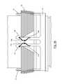
- FIG. 5is an exploded, side view showing the component parts of the connector.
- FIG. 6is an exploded, perspective view showing the component parts of the connector.
- FIG. 7is a perspective view of the base ring and claws.
- FIG. 8is a perspective view of the main sleeve.
- FIG. 9is a perspective view showing the base ring mounted to the main sleeve.
- FIG. 10is a perspective view of the connector.
- FIG. 11is a perspective view showing the connector approaching the pump outlet port.
- FIG. 12is a cross-sectional view of the connector sliding onto the pump outlet port.
- FIG. 13is a cross section of the connector and outlet port just before a “soft” connection is made.
- FIG. 14is a cross section of the connector and outlet port after a “soft” connection has been made.
- FIG. 15is a cross section of the connector and outlet port after a “hard” connection has been made.
- FIG. 16is a perspective view of another embodiment of the connector and outlet port prior to interconnecting them.
- FIG. 17is a perspective view of the connector and outlet port of FIG. 16 in a “soft” connection.
- FIG. 18is a cross-sectional view of the connector and outlet port of FIG. 16 .
- FIG. 19is a side, plan view showing the prongs being inserted into a groove on the outlet port.
- FIG. 20is a cross-section of the connector and outlet port of FIG. 16 in a “soft” connection.
- FIG. 21is a cross-section of the connector and outlet port of FIG. 16 in a “hard” connection.
- a patient 10is shown in fragmentary front elevational view.
- Surgically implanted into the patient's abdominal cavity or pericardium 11is the pumping portion 12 of a ventricular assist device 13 .
- An inflow conduit 14conveys blood from the patient's left ventricle into the pumping portion 12
- an outflow conduit 15conveys blood from the pumping portion 12 to the patient's ascending thoracic aorta.
- a power cable 16extends from the pumping portion 12 outwardly of the patient's body via an incision to a compact controller 17 .
- a power source, such as battery packs 18is worn on a belt about the patient's waist and connected with controller 17 .
- FIG. 2shows an outflow conduit assembly 20 which includes a woven Dacron graft 21 .
- a first end 22 of graft 21may be sutured to the patient's aorta, for example.
- a second end 23 of graft 21is joined with a connector 24 .
- a plastic cage 25is preferably mounted over graft 21 at second end 23 to prevent graft 21 from collapsing or kinking in an area where graft 21 must make its sharpest bend after implantation in a patient (e.g., to curve around the heart itself).
- FIG. 3shows a pump 26 with an inlet conduit 27 which is inserted into the left ventricle.
- Pump 26has an outlet port 28 which receives connector 24 .
- inlet conduit 27 and pump 26may be joined with the ventricle prior to final placement and attachment of outflow conduit 20 .
- connector 24it may also be desirable for connector 24 to be 1) easily repositionable on outlet port 28 for proper orientation, and 2) easily removable in order to obtain back-bleeding through outflow conduit 20 in order to expel air.
- the present inventionprovides a “soft” connection during implantation to make it removable and repositionable and a “hard” connection to ensure a secure and immovable retention following implantation.
- connector 25includes a main sleeve 30 formed as a generally cylindrical, metal body.
- a crimp fitting 31interconnects main sleeve 30 with graft 21 and cage 25 .
- Main sleeve 30also carries a spring washer 32 , a base ring 33 having a plurality of prongs 34 , and a lock nut 35 .
- Sleeve 30has a threaded region 36 and an outward flange 37 at the end proximate to the pump outlet port.
- the pump outlet portincludes a tube 40 extending from the external housing of pump 26 .
- An adaptor 41 having a circumferential groove 42 defining a lip 43is fitted over tube 40 .
- Adaptor 41may be welded to tube 40 and pump 26 , for example.
- a seal 44is received by adaptor 41 against a sealing surface 45 . Seal 44 is compressed between the outlet port and flange 37 when a connection is made as described below.
- FIG. 6shows crimping connection 31 which connects with end 29 of sleeve 30 .
- Sleeve 30has projections 48 spaced from flange 37 .
- Spring washer 32 and base ring 33are installed between flange 37 and projections 48 .
- Locking nut 35has internal threads 38 which are threaded onto external threads 36 of sleeve 30 .
- Grippers 39extend on the outer surface of lock nut 35 to facilitate grasping by the fingers during manual rotation of lock nut 35 .
- base ring 33includes recesses 47 on its inside diameter.
- FIG. 7shows an embodiment with a different number of prongs 34 than in FIGS. 4-6 .
- the spacing between recesses 47matches the spacing of projections 48 on sleeve 30 as shown in FIG. 8 .
- Spring washer 32is preferably formed as a wavy C-ring so that its inside diameter allows it to fit over projections 48 . After placing spring washer 32 proximate to an inside edge of flange 37 , base ring 33 is slipped onto sleeve 30 toward flange 37 by aligning grooves 47 with projections 48 and compressing it against spring washer 32 .
- base ring 33is rotated so that projections 48 align with matching notches 50 located between partial recesses 47 .
- Spring washer 32tries to expand so that it locks base ring 33 in position.
- prongs 34extend from base ring 33 over flange 37 as shown in FIG. 9 . Because of the foregoing arrangement, base ring 33 is keyed with projections 48 on main sleeve 30 so that base ring 33 and prongs 34 are held firmly in place on the end of sleeve 30 .
- Prongs 34have respective claws 51 at their distal ends.
- Each prongextends substantially parallel to a longitudinal axis of sleeve 30 , and each prong 34 is outwardly bendable so that respective claws 51 are expandable to interconnect with the pump outlet port as explained below.
- FIG. 10illustrates the relative position of base ring 33 to locknut 35 with the main sleeve being removed for clarity.
- FIG. 11shows connector 24 being aligned with outlet port 28 on pump 26 in order to initiate an interconnection.
- FIG. 12is a cross-sectional view showing the further progression of a connection, wherein main sleeve 30 is advanced coaxially toward tube 40 and adaptor 41 .
- Locknut 35is movable via the cooperation of threaded areas 36 / 38 between a retracted position as shown in FIG. 12 and a locking position to be described in connection with FIG. 15 . With locknut 35 in the retracted position, prongs 34 are unrestrained so that they are bendable outwardly.
- Main sleeve 30has an inner receiving surface 55 complementary with the surface of adaptor 41 .
- Claws 51are positioned to interact with adaptor 41 such that they bend outwardly in order to slide over lip 43 and enter groove 42 .
- FIG. 13illustrates claw 51 at the beginning of its interact with lip 43 .
- a sloped edge of claw 51guides claw 51 outward as main sleeve 30 slides to the right in FIG. 13 .
- claw 51enters groove 42 as shown in FIG. 14 .
- Sleeve 30 and tube 40provide a continuous inside diameter for a smooth flow of blood. Seal 34 is compressed between adaptor 41 and sleeve 30 to prevent leakage. In the “soft connect” condition shown in FIG. 14 , the connector is movably retained on the outlet port.
- the connectoris retained to the outlet port while being repositionable, e.g., by rotation of claws 51 circumferentially along circumferential groove 42 to allow adjustment of the positioning of the outflow conduit prior to making a hard, immovable connection.
- a surgeonadjusts the position of the outflow conduit until a final orientation is reached.
- the surgeonmay also remove the connector after the other end of the outflow conduit is attached to the aorta for the purpose of back-bleeding to remove air from the outflow conduit. The removal and reconnection/realignment of the connector can be done easily with minimal force.
- FIG. 15shows the “hard connect” state of the connector wherein locknut 35 is advanced to the locking position, whereby a bearing surface 56 on the inside diameter of lock nut 35 bears against prongs 34 to prevent their outward bending. Since claws 51 cannot expand over lip 43 and are instead clamped down against groove 42 , the connector is rigidly retained on the outlet port. Rotating locking nut 35 to traverse the threads and move it back to the retracted position would allow further adjustment of the position on the outlet port.
- the complementary tapering of claw 50 and circumferential groove 42allow easy removal by pulling the connector away from the outlet port (e.g., by grasping lock nut 35 ) so that prongs 34 expand at their ends and claws 51 expand over lip 43 . In the hard locked position, the taper of claws 51 and groove 42 pull sleeve 30 toward the pump so that flange 37 compresses seal 44 .
- FIGS. 16-21show an alternative embodiment wherein axially-extending prongs are received in axially-extending grooves instead of a circumferential groove.
- FIG. 16shows a pump 60 including an inflow conduit 61 and an outlet port 62 for receiving an outflow conduit 63 .
- a connector 64is capable of “soft” and “hard” connections with outlet port 62 .
- Outlet port 62has external threads 66 that are configured to mesh with a lock nut 75 . Portions of thread 66 are removed in order to create a series of axial grooves 67 spaced around the periphery of outlet port 62 .
- Connector 64has a plurality of prongs 70 extending axially from a main sleeve 71 . Preferably, prongs 70 extend in matching pairs, each with oppositely-directed claws 72 . Each pair of prongs 70 aligns with a respective groove 76 .
- FIG. 17shows the soft connection wherein each pair of prongs 70 is captured within a corresponding groove 67 .
- Lock nut 75is shown in a retracted position which allows main sleeve 71 and outflow conduit 63 to rotate while being implanted during surgery.
- FIG. 18shows the elements of the connector and outlet port in greater detail.
- a ring carrying threads 66may be welded to outlet port 62 .
- a compression seal 77is installed at the distal end of threads 66 .
- Main sleeve 71includes a proximal section 71 A and a distal section 71 B, each cylindrical in shape and which may be welded together.
- the outer edge of proximal section 71 Ahas a stepped configuration with a first pocket 80 which receives a base ring 81 (from which prongs 70 extend, similar to the previous embodiment).
- the fit between base ring 81 and pocket 80is sufficiently loose that ring 81 is able to rotate circumferentially in pocket 80 .
- a deeper pocket 82 adjacent to pocket 80receives a C-shaped or expandable clip 83 for keeping base ring 81 in place.
- base ring 81 with prongs 70is slid onto proximal sleeve section 71 A until it stops in pocket 80 .
- Clip 83is inserted into pocket 82 , and then lock nut 75 is slid onto proximal sleeve section 71 A (e.g., until an inside shoulder 85 contacts clip 83 .
- proximal sleeve section 71 Ais welded to distal sleeve section 71 B.
- a conventional graft portion of the outflow conduitis attached by crimping.
- a graft 90 with a cylindrical collar 91is fitted over a distal end 92 of main sleeve 71 and attached by a crimp ring 93 by pinching its end 93 A over a corresponding ridge on sleeve section 71 B.
- a protective cage 94is held in place over an outer edge of crimp ring 93 by a cover sleeve 95 which is crimped onto ring 93 .
- FIG. 19illustrates the manner in which a soft connection is obtained by advancing prongs 70 into grooves 67 on outlet port 62 .
- a groove 67has opposing ramp-shaped sides to form lips 67 A and 67 B.
- Claws 72 A and 72 B at the ends of prongs 70 A and 70 Bare gradually pinched together as they advance through groove 67 , and they expand apart after passing beyond lips 67 A and 67 B, respectively.
- Prongs 70 and base ring 81are retained in the position shown in FIG. 19 in a loose condition since some amount of play is permitted as long as the lock nut is not tightened (the lock nut is not shown in FIG. 19 for clarity).
- Main sleeveis allowed to rotate within base ring 81 , thereby facilitating adjustment by a surgeon during implantation. It is also possible to disconnect prongs 70 from outlet port 62 , but the required force is higher since the axial distance over which prongs 70 A and 70 B must squeeze together is much shorter.
- FIG. 20shows lock nut 75 in its retracted position and proximal sleeve section 71 A inserted on outlet port 62 .
- Proximal edge 86 of sleeve section 71 Agently contacts seal 77 so that rotation is permitted.
- lock nut 75has been turned onto threads 66 so that it has advanced to its locking position. Shoulder 85 of lock nut 75 is drawn against clip 83 by the action of threads 66 / 78 .
- Proximal edge 86compresses seal 77 to prevent leakage of blood around the connector.
Landscapes
- Health & Medical Sciences (AREA)
- Heart & Thoracic Surgery (AREA)
- Engineering & Computer Science (AREA)
- Veterinary Medicine (AREA)
- Anesthesiology (AREA)
- Biomedical Technology (AREA)
- Hematology (AREA)
- Life Sciences & Earth Sciences (AREA)
- Animal Behavior & Ethology (AREA)
- General Health & Medical Sciences (AREA)
- Public Health (AREA)
- Cardiology (AREA)
- Mechanical Engineering (AREA)
- Pulmonology (AREA)
- External Artificial Organs (AREA)
- Prostheses (AREA)
Abstract
Description
Claims (15)
Priority Applications (2)
| Application Number | Priority Date | Filing Date | Title |
|---|---|---|---|
| US13/405,784US8882744B2 (en) | 2012-02-27 | 2012-02-27 | Quick-connect outflow tube for ventricular assist device |
| PCT/US2013/025703WO2013130259A1 (en) | 2012-02-27 | 2013-02-12 | Quick-connect outflow tube for ventricular assist device |
Applications Claiming Priority (1)
| Application Number | Priority Date | Filing Date | Title |
|---|---|---|---|
| US13/405,784US8882744B2 (en) | 2012-02-27 | 2012-02-27 | Quick-connect outflow tube for ventricular assist device |
Publications (2)
| Publication Number | Publication Date |
|---|---|
| US20130225909A1 US20130225909A1 (en) | 2013-08-29 |
| US8882744B2true US8882744B2 (en) | 2014-11-11 |
Family
ID=49003597
Family Applications (1)
| Application Number | Title | Priority Date | Filing Date |
|---|---|---|---|
| US13/405,784Expired - Fee RelatedUS8882744B2 (en) | 2012-02-27 | 2012-02-27 | Quick-connect outflow tube for ventricular assist device |
Country Status (2)
| Country | Link |
|---|---|
| US (1) | US8882744B2 (en) |
| WO (1) | WO2013130259A1 (en) |
Cited By (21)
| Publication number | Priority date | Publication date | Assignee | Title |
|---|---|---|---|---|
| US9623161B2 (en) | 2014-08-26 | 2017-04-18 | Tc1 Llc | Blood pump and method of suction detection |
| WO2019139686A1 (en) | 2018-01-10 | 2019-07-18 | Tc1 Llc | Bearingless implantable blood pump |
| EP3597231A1 (en) | 2018-07-17 | 2020-01-22 | Tc1 Llc | Systems and methods for inertial sensing for vad diagnostics and closed loop control |
| WO2020068333A1 (en) | 2018-09-25 | 2020-04-02 | Tc1 Llc | Adaptive speed control algorithms and controllers for optimizing flow in ventricular assist devices |
| US10722631B2 (en) | 2018-02-01 | 2020-07-28 | Shifamed Holdings, Llc | Intravascular blood pumps and methods of use and manufacture |
| US11185677B2 (en) | 2017-06-07 | 2021-11-30 | Shifamed Holdings, Llc | Intravascular fluid movement devices, systems, and methods of use |
| US11511103B2 (en) | 2017-11-13 | 2022-11-29 | Shifamed Holdings, Llc | Intravascular fluid movement devices, systems, and methods of use |
| US11654275B2 (en) | 2019-07-22 | 2023-05-23 | Shifamed Holdings, Llc | Intravascular blood pumps with struts and methods of use and manufacture |
| US11724089B2 (en) | 2019-09-25 | 2023-08-15 | Shifamed Holdings, Llc | Intravascular blood pump systems and methods of use and control thereof |
| WO2023158493A1 (en) | 2022-02-16 | 2023-08-24 | Tc1 Llc | Real time heart rate monitoring for close loop control and/or artificial pulse synchronization of implantable ventricular assist devices |
| WO2023229899A1 (en) | 2022-05-26 | 2023-11-30 | Tc1 Llc | Tri-axis accelerometers for patient physiologic monitoring and closed loop control of implantable ventricular assist devices |
| WO2023235230A1 (en) | 2022-06-02 | 2023-12-07 | Tc1 Llc | Implanted connector booster sealing for implantable medical devices |
| WO2024050319A1 (en) | 2022-08-29 | 2024-03-07 | Tc1 Llc | Implantable electrical connector assembly |
| US11964145B2 (en) | 2019-07-12 | 2024-04-23 | Shifamed Holdings, Llc | Intravascular blood pumps and methods of manufacture and use |
| WO2024097236A1 (en) | 2022-11-01 | 2024-05-10 | Tc1 Llc | Assessment and management of adverse event risks in mechanical circulatory support patients |
| US12102815B2 (en) | 2019-09-25 | 2024-10-01 | Shifamed Holdings, Llc | Catheter blood pumps and collapsible pump housings |
| US12121713B2 (en) | 2019-09-25 | 2024-10-22 | Shifamed Holdings, Llc | Catheter blood pumps and collapsible blood conduits |
| US12161857B2 (en) | 2018-07-31 | 2024-12-10 | Shifamed Holdings, Llc | Intravascular blood pumps and methods of use |
| US12220570B2 (en) | 2018-10-05 | 2025-02-11 | Shifamed Holdings, Llc | Intravascular blood pumps and methods of use |
| WO2025137296A1 (en) | 2023-12-22 | 2025-06-26 | Tc1 Llc | Utilization of a left-ventricular pressure sensor for measurement of left-atrial and aortic pressure |
| US12409310B2 (en) | 2019-12-11 | 2025-09-09 | Shifamed Holdings, Llc | Descending aorta and vena cava blood pumps |
Families Citing this family (57)
| Publication number | Priority date | Publication date | Assignee | Title |
|---|---|---|---|---|
| JP5577506B2 (en) | 2010-09-14 | 2014-08-27 | ソーラテック コーポレイション | Centrifugal pump device |
| EP2693609B1 (en) | 2011-03-28 | 2017-05-03 | Thoratec Corporation | Rotation and drive device and centrifugal pump device using same |
| US8864643B2 (en) | 2011-10-13 | 2014-10-21 | Thoratec Corporation | Pump and method for mixed flow blood pumping |
| US9371826B2 (en) | 2013-01-24 | 2016-06-21 | Thoratec Corporation | Impeller position compensation using field oriented control |
| US10052420B2 (en) | 2013-04-30 | 2018-08-21 | Tc1 Llc | Heart beat identification and pump speed synchronization |
| US9744280B2 (en) | 2014-04-15 | 2017-08-29 | Tc1 Llc | Methods for LVAD operation during communication losses |
| US9694123B2 (en) | 2014-04-15 | 2017-07-04 | Tc1 Llc | Methods and systems for controlling a blood pump |
| WO2015160994A1 (en) | 2014-04-15 | 2015-10-22 | Thoratec Corporation | Methods and systems for upgrading ventricle assist devices |
| WO2015160993A1 (en) | 2014-04-15 | 2015-10-22 | Thoratec Corporation | Methods and systems for providing battery feedback to patient |
| US9849224B2 (en) | 2014-04-15 | 2017-12-26 | Tc1 Llc | Ventricular assist devices |
| US9526818B2 (en) | 2014-04-15 | 2016-12-27 | Thoratec Corporation | Protective cap for driveline cable connector |
| US20160058930A1 (en)* | 2014-08-26 | 2016-03-03 | Thoratec Corporation | Blood pump and method of suction detection |
| JP6228713B1 (en) | 2014-09-03 | 2017-11-08 | ティーシー1 エルエルシー | Triple helical driveline cable and method of assembly and use |
| WO2016086137A1 (en) | 2014-11-26 | 2016-06-02 | Thoratec Corporation | Pump and method for mixed flow blood pumping |
| EP3256183B1 (en) | 2015-02-11 | 2025-08-13 | Tc1 Llc | Heart beat identification and pump speed synchronization |
| EP3256185B1 (en) | 2015-02-12 | 2019-10-30 | Tc1 Llc | System and method for controlling the position of a levitated rotor |
| US10371152B2 (en) | 2015-02-12 | 2019-08-06 | Tc1 Llc | Alternating pump gaps |
| EP3256184B1 (en) | 2015-02-13 | 2020-04-08 | Tc1 Llc | Impeller suspension mechanism for heart pump |
| WO2016187057A1 (en) | 2015-05-15 | 2016-11-24 | Thoratec Corporation | Improved axial flow blood pump |
| EP3324840A4 (en) | 2015-07-20 | 2019-03-20 | Tc1 Llc | TENSIOMETER FOR FLOW ESTIMATION |
| US9901666B2 (en) | 2015-07-20 | 2018-02-27 | Tc1 Llc | Flow estimation using hall-effect sensors for measuring impeller eccentricity |
| EP3325036B1 (en) | 2015-07-21 | 2021-02-24 | Tc1 Llc | Cantilevered rotor pump for axial flow blood pumping |
| US20220296869A1 (en)* | 2015-08-13 | 2022-09-22 | Site Saver, Inc. | Breakaway medical tubing connector |
| EP3340925B1 (en) | 2015-08-28 | 2020-09-23 | Tc1 Llc | Blood pump controllers and methods of use for improved energy efficiency |
| US10117983B2 (en) | 2015-11-16 | 2018-11-06 | Tc1 Llc | Pressure/flow characteristic modification of a centrifugal pump in a ventricular assist device |
| EP3377135B1 (en) | 2015-11-20 | 2020-05-06 | Tc1 Llc | Blood pump controllers having daisy-chained batteries |
| EP3377133B1 (en) | 2015-11-20 | 2021-07-14 | Tc1 Llc | System architecture that allows patient replacement of vad controller/interface module without disconnection of old module |
| EP3377136B1 (en) | 2015-11-20 | 2020-05-06 | Tc1 Llc | Energy management of blood pump controllers |
| WO2017087728A1 (en) | 2015-11-20 | 2017-05-26 | Tc1 Llc | Improved connectors and cables for use with ventricle assist systems |
| US9985374B2 (en) | 2016-05-06 | 2018-05-29 | Tc1 Llc | Compliant implantable connector and methods of use and manufacture |
| WO2018017716A1 (en) | 2016-07-21 | 2018-01-25 | Tc1 Llc | Rotary seal for cantilevered rotor pump and methods for axial flow blood pumping |
| US10660998B2 (en) | 2016-08-12 | 2020-05-26 | Tci Llc | Devices and methods for monitoring bearing and seal performance |
| US10589013B2 (en) | 2016-08-26 | 2020-03-17 | Tci Llc | Prosthetic rib with integrated percutaneous connector for ventricular assist devices |
| WO2018057795A1 (en) | 2016-09-26 | 2018-03-29 | Tc1 Llc | Heart pump driveline power modulation |
| US10665080B2 (en) | 2016-10-20 | 2020-05-26 | Tc1 Llc | Methods and systems for bone conduction audible alarms for mechanical circulatory support systems |
| WO2018132708A1 (en) | 2017-01-12 | 2018-07-19 | Tc1 Llc | Percutaneous driveline anchor devices and methods of use |
| US10894114B2 (en) | 2017-01-12 | 2021-01-19 | Tc1 Llc | Driveline bone anchors and methods of use |
| WO2018136592A2 (en) | 2017-01-18 | 2018-07-26 | Tc1 Llc | Systems and methods for transcutaneous power transfer using microneedles |
| WO2018195301A1 (en) | 2017-04-21 | 2018-10-25 | Tc1 Llc | Aortic connectors and methods of use |
| US10737007B2 (en) | 2017-04-28 | 2020-08-11 | Tc1 Llc | Patient adapter for driveline cable and methods |
| WO2019135876A1 (en) | 2018-01-02 | 2019-07-11 | Tc1 Llc | Fluid treatment system for a driveline and methods of assembly and use |
| US10701043B2 (en) | 2018-01-17 | 2020-06-30 | Tc1 Llc | Methods for physical authentication of medical devices during wireless pairing |
| US11529508B2 (en) | 2018-03-02 | 2022-12-20 | Tc1 Llc | Wearable accessory for ventricular assist system |
| WO2019183126A1 (en) | 2018-03-20 | 2019-09-26 | Tc1 Llc | Mechanical gauge for estimating inductance changes in resonant power transfer systems with flexible coils for use with implanted medical devices |
| WO2019182691A1 (en) | 2018-03-21 | 2019-09-26 | Tc1 Llc | Improved driveline connectors and methods for use with heart pump controllers |
| US11389641B2 (en) | 2018-03-21 | 2022-07-19 | Tc1 Llc | Modular flying lead cable and methods for use with heart pump controllers |
| US11076944B2 (en) | 2018-03-26 | 2021-08-03 | Tc1 Llc | Methods and systems for irrigating and capturing particulates during heart pump implantation |
| EP3787707B1 (en) | 2018-04-30 | 2023-12-27 | Tc1 Llc | Improved blood pump connectors |
| WO2019232080A1 (en) | 2018-05-31 | 2019-12-05 | Tc1 Llc | Improved blood pump controllers |
| WO2020081321A1 (en)* | 2018-10-19 | 2020-04-23 | Tc1 Llc | Implantable blood pump assembly including outflow graft fixation clip |
| JP6617323B1 (en)* | 2018-10-26 | 2019-12-11 | 株式会社サンメディカル技術研究所 | Medical tube protector |
| US20220161022A1 (en)* | 2019-04-05 | 2022-05-26 | Scandinavian Real Heart Ab | A vascular coupling device |
| US11638813B2 (en)* | 2019-09-24 | 2023-05-02 | Tc1 Llc | Implantable blood pump assembly including anti-rotation mechanism for outflow cannula and method of assembling same |
| US20210361932A1 (en)* | 2020-05-20 | 2021-11-25 | Tc1 Llc | Systems and methods for blood pump connectors |
| US20220331580A1 (en) | 2021-04-15 | 2022-10-20 | Tc1 Llc | Systems and methods for medical device connectors |
| CN116637292A (en)* | 2023-05-29 | 2023-08-25 | 上海焕擎医疗科技有限公司 | Connection assembly and heart assist device |
| CN117398595B (en)* | 2023-12-15 | 2024-02-23 | 苏州同心医疗科技股份有限公司 | Blood pump outlet pipe connection structure |
Citations (14)
| Publication number | Priority date | Publication date | Assignee | Title |
|---|---|---|---|---|
| US5810708A (en) | 1994-02-07 | 1998-09-22 | Baxter International Inc. | Ventricular assist conduit with externally supported tissue valve |
| US6001056A (en) | 1998-11-13 | 1999-12-14 | Baxter International Inc. | Smooth ventricular assist device conduit |
| US6050987A (en) | 1998-09-21 | 2000-04-18 | The United States Of America As Represented By The Administrator Of The National Aeronautics And Space Administration | Tubular coupling |
| US6264248B1 (en) | 1997-06-03 | 2001-07-24 | Sevylor International | Quick coupling for a hose |
| US6319231B1 (en) | 1999-02-12 | 2001-11-20 | Abiomed, Inc. | Medical connector |
| US20040171905A1 (en) | 2002-06-26 | 2004-09-02 | HeartWare, Inc, (a Delaware Corporation) | Ventricular connector |
| US7048681B2 (en) | 2003-03-28 | 2006-05-23 | Terumo Corporation | Method and apparatus for adjusting a length of the inflow conduit on a ventricular assist device |
| US7172550B2 (en) | 2003-07-31 | 2007-02-06 | Terumo Corporation | Adjustable coupling mechanism for the conduit on a ventricular assist device |
| US20070134993A1 (en) | 2005-12-08 | 2007-06-14 | Daniel Tamez | Implant connector |
| US7303553B2 (en)* | 2002-06-24 | 2007-12-04 | Berlin Heart Gmbh | Device for connecting a cannula made of a flexible material with a tube |
| US7824358B2 (en) | 2004-07-22 | 2010-11-02 | Thoratec Corporation | Heart pump connector |
| US20120095281A1 (en) | 2010-10-13 | 2012-04-19 | Reichenbach Steven H | Pumping blood |
| US20120209057A1 (en) | 2009-09-30 | 2012-08-16 | Abiomed Europe Gmbh | Lockable quick coupling |
| US20130096364A1 (en) | 2011-10-13 | 2013-04-18 | Steven H. Reichenbach | Pump and method for mixed flow blood pumping |
Family Cites Families (1)
| Publication number | Priority date | Publication date | Assignee | Title |
|---|---|---|---|---|
| JP3798928B2 (en)* | 1999-11-16 | 2006-07-19 | ペンタックス株式会社 | Connection structure of tube and base of endoscope treatment tool |
- 2012
- 2012-02-27USUS13/405,784patent/US8882744B2/ennot_activeExpired - Fee Related
- 2013
- 2013-02-12WOPCT/US2013/025703patent/WO2013130259A1/enactiveApplication Filing
Patent Citations (14)
| Publication number | Priority date | Publication date | Assignee | Title |
|---|---|---|---|---|
| US5810708A (en) | 1994-02-07 | 1998-09-22 | Baxter International Inc. | Ventricular assist conduit with externally supported tissue valve |
| US6264248B1 (en) | 1997-06-03 | 2001-07-24 | Sevylor International | Quick coupling for a hose |
| US6050987A (en) | 1998-09-21 | 2000-04-18 | The United States Of America As Represented By The Administrator Of The National Aeronautics And Space Administration | Tubular coupling |
| US6001056A (en) | 1998-11-13 | 1999-12-14 | Baxter International Inc. | Smooth ventricular assist device conduit |
| US6319231B1 (en) | 1999-02-12 | 2001-11-20 | Abiomed, Inc. | Medical connector |
| US7303553B2 (en)* | 2002-06-24 | 2007-12-04 | Berlin Heart Gmbh | Device for connecting a cannula made of a flexible material with a tube |
| US20040171905A1 (en) | 2002-06-26 | 2004-09-02 | HeartWare, Inc, (a Delaware Corporation) | Ventricular connector |
| US7048681B2 (en) | 2003-03-28 | 2006-05-23 | Terumo Corporation | Method and apparatus for adjusting a length of the inflow conduit on a ventricular assist device |
| US7172550B2 (en) | 2003-07-31 | 2007-02-06 | Terumo Corporation | Adjustable coupling mechanism for the conduit on a ventricular assist device |
| US7824358B2 (en) | 2004-07-22 | 2010-11-02 | Thoratec Corporation | Heart pump connector |
| US20070134993A1 (en) | 2005-12-08 | 2007-06-14 | Daniel Tamez | Implant connector |
| US20120209057A1 (en) | 2009-09-30 | 2012-08-16 | Abiomed Europe Gmbh | Lockable quick coupling |
| US20120095281A1 (en) | 2010-10-13 | 2012-04-19 | Reichenbach Steven H | Pumping blood |
| US20130096364A1 (en) | 2011-10-13 | 2013-04-18 | Steven H. Reichenbach | Pump and method for mixed flow blood pumping |
Non-Patent Citations (1)
| Title |
|---|
| International Preliminary Report on Patentability of PCT/US13/25703, mailed Jan. 10, 2014, 10 pages. |
Cited By (33)
| Publication number | Priority date | Publication date | Assignee | Title |
|---|---|---|---|---|
| US9623161B2 (en) | 2014-08-26 | 2017-04-18 | Tc1 Llc | Blood pump and method of suction detection |
| US11717670B2 (en) | 2017-06-07 | 2023-08-08 | Shifamed Holdings, LLP | Intravascular fluid movement devices, systems, and methods of use |
| US11185677B2 (en) | 2017-06-07 | 2021-11-30 | Shifamed Holdings, Llc | Intravascular fluid movement devices, systems, and methods of use |
| US11511103B2 (en) | 2017-11-13 | 2022-11-29 | Shifamed Holdings, Llc | Intravascular fluid movement devices, systems, and methods of use |
| WO2019139686A1 (en) | 2018-01-10 | 2019-07-18 | Tc1 Llc | Bearingless implantable blood pump |
| US12383725B2 (en) | 2018-01-10 | 2025-08-12 | Tc1 Llc | Bearingless implantable blood pump |
| US10973967B2 (en) | 2018-01-10 | 2021-04-13 | Tc1 Llc | Bearingless implantable blood pump |
| EP4275737A2 (en) | 2018-01-10 | 2023-11-15 | Tc1 Llc | Bearingless implantable blood pump |
| US12076545B2 (en) | 2018-02-01 | 2024-09-03 | Shifamed Holdings, Llc | Intravascular blood pumps and methods of use and manufacture |
| US10722631B2 (en) | 2018-02-01 | 2020-07-28 | Shifamed Holdings, Llc | Intravascular blood pumps and methods of use and manufacture |
| US11229784B2 (en) | 2018-02-01 | 2022-01-25 | Shifamed Holdings, Llc | Intravascular blood pumps and methods of use and manufacture |
| US12064612B2 (en) | 2018-07-17 | 2024-08-20 | Tc1 Llc | Systems and methods for inertial sensing for VAD diagnostics and closed loop control |
| US11241570B2 (en) | 2018-07-17 | 2022-02-08 | Tc1 Llc | Systems and methods for inertial sensing for VAD diagnostics and closed loop control |
| EP3597231A1 (en) | 2018-07-17 | 2020-01-22 | Tc1 Llc | Systems and methods for inertial sensing for vad diagnostics and closed loop control |
| EP4190392A1 (en) | 2018-07-17 | 2023-06-07 | Tc1 Llc | Systems and methods for inertial sensing for vad diagnostics and closed loop control |
| US12161857B2 (en) | 2018-07-31 | 2024-12-10 | Shifamed Holdings, Llc | Intravascular blood pumps and methods of use |
| US11241572B2 (en) | 2018-09-25 | 2022-02-08 | Tc1 Llc | Adaptive speed control algorithms and controllers for optimizing flow in ventricular assist devices |
| EP4360691A2 (en) | 2018-09-25 | 2024-05-01 | Tc1 Llc | Adaptive speed control algorithms and controllers for optimizing flow in ventricular assist devices |
| US11998730B2 (en) | 2018-09-25 | 2024-06-04 | Tc1 Llc | Adaptive speed control algorithms and controllers for optimizing flow in ventricular assist devices |
| WO2020068333A1 (en) | 2018-09-25 | 2020-04-02 | Tc1 Llc | Adaptive speed control algorithms and controllers for optimizing flow in ventricular assist devices |
| US12220570B2 (en) | 2018-10-05 | 2025-02-11 | Shifamed Holdings, Llc | Intravascular blood pumps and methods of use |
| US11964145B2 (en) | 2019-07-12 | 2024-04-23 | Shifamed Holdings, Llc | Intravascular blood pumps and methods of manufacture and use |
| US11654275B2 (en) | 2019-07-22 | 2023-05-23 | Shifamed Holdings, Llc | Intravascular blood pumps with struts and methods of use and manufacture |
| US11724089B2 (en) | 2019-09-25 | 2023-08-15 | Shifamed Holdings, Llc | Intravascular blood pump systems and methods of use and control thereof |
| US12102815B2 (en) | 2019-09-25 | 2024-10-01 | Shifamed Holdings, Llc | Catheter blood pumps and collapsible pump housings |
| US12121713B2 (en) | 2019-09-25 | 2024-10-22 | Shifamed Holdings, Llc | Catheter blood pumps and collapsible blood conduits |
| US12409310B2 (en) | 2019-12-11 | 2025-09-09 | Shifamed Holdings, Llc | Descending aorta and vena cava blood pumps |
| WO2023158493A1 (en) | 2022-02-16 | 2023-08-24 | Tc1 Llc | Real time heart rate monitoring for close loop control and/or artificial pulse synchronization of implantable ventricular assist devices |
| WO2023229899A1 (en) | 2022-05-26 | 2023-11-30 | Tc1 Llc | Tri-axis accelerometers for patient physiologic monitoring and closed loop control of implantable ventricular assist devices |
| WO2023235230A1 (en) | 2022-06-02 | 2023-12-07 | Tc1 Llc | Implanted connector booster sealing for implantable medical devices |
| WO2024050319A1 (en) | 2022-08-29 | 2024-03-07 | Tc1 Llc | Implantable electrical connector assembly |
| WO2024097236A1 (en) | 2022-11-01 | 2024-05-10 | Tc1 Llc | Assessment and management of adverse event risks in mechanical circulatory support patients |
| WO2025137296A1 (en) | 2023-12-22 | 2025-06-26 | Tc1 Llc | Utilization of a left-ventricular pressure sensor for measurement of left-atrial and aortic pressure |
Also Published As
| Publication number | Publication date |
|---|---|
| WO2013130259A1 (en) | 2013-09-06 |
| US20130225909A1 (en) | 2013-08-29 |
| WO2013130259A8 (en) | 2013-11-14 |
Similar Documents
| Publication | Publication Date | Title |
|---|---|---|
| US8882744B2 (en) | Quick-connect outflow tube for ventricular assist device | |
| US8840538B2 (en) | Apical ring for ventricular assist device | |
| US10632296B2 (en) | Vascular access system with connector | |
| US11583671B2 (en) | Heart pump cuff | |
| US20240207595A1 (en) | Lockable quick coupling | |
| US7824358B2 (en) | Heart pump connector | |
| US20140303427A1 (en) | Blood flow system with operator attachable components | |
| US8652024B1 (en) | Sterilizable cable system for implantable blood pump | |
| US7172550B2 (en) | Adjustable coupling mechanism for the conduit on a ventricular assist device | |
| US10687815B2 (en) | Clip for a medical implant | |
| US20150025437A1 (en) | Vascular access system with connector | |
| US11801379B2 (en) | Aortic connectors and methods of use | |
| EP4593932A1 (en) | Implantable heart pump system including an improved apical connector and/or graft connector | |
| US20210205603A1 (en) | Device for anchoring a heart pump | |
| CN115105256B (en) | Heart Valve Delivery Systems | |
| US11925382B2 (en) | Coring device and coring and insertion assembly comprising such a device | |
| GB2620846A (en) | Endo-leak free aortic adapter assembly and method of device delivery |
Legal Events
| Date | Code | Title | Description |
|---|---|---|---|
| AS | Assignment | Owner name:TERUMO KABUSHIKI KAISHA, JAPAN Free format text:ASSIGNMENT OF ASSIGNORS INTEREST;ASSIGNORS:DORMANEN, CHRISTOPHER P.;DASARA, SUNIL K.;TSUBOUCHI, TAKESHI;SIGNING DATES FROM 20120217 TO 20120223;REEL/FRAME:027767/0639 | |
| AS | Assignment | Owner name:THORATEC CORPORATION, CALIFORNIA Free format text:ASSIGNMENT OF ASSIGNORS INTEREST;ASSIGNOR:TERUMO KABUSHIKI KAISHA;REEL/FRAME:031016/0364 Effective date:20130630 | |
| STCF | Information on status: patent grant | Free format text:PATENTED CASE | |
| AS | Assignment | Owner name:THORATEC LLC, CALIFORNIA Free format text:CHANGE OF NAME;ASSIGNOR:THORATEC CORPORATION;REEL/FRAME:041428/0327 Effective date:20151112 Owner name:TC1 LLC, CALIFORNIA Free format text:ASSIGNMENT OF ASSIGNORS INTEREST;ASSIGNOR:THORATEC LLC;REEL/FRAME:041428/0685 Effective date:20161114 | |
| MAFP | Maintenance fee payment | Free format text:PAYMENT OF MAINTENANCE FEE, 4TH YEAR, LARGE ENTITY (ORIGINAL EVENT CODE: M1551) Year of fee payment:4 | |
| FEPP | Fee payment procedure | Free format text:MAINTENANCE FEE REMINDER MAILED (ORIGINAL EVENT CODE: REM.); ENTITY STATUS OF PATENT OWNER: LARGE ENTITY | |
| LAPS | Lapse for failure to pay maintenance fees | Free format text:PATENT EXPIRED FOR FAILURE TO PAY MAINTENANCE FEES (ORIGINAL EVENT CODE: EXP.); ENTITY STATUS OF PATENT OWNER: LARGE ENTITY | |
| STCH | Information on status: patent discontinuation | Free format text:PATENT EXPIRED DUE TO NONPAYMENT OF MAINTENANCE FEES UNDER 37 CFR 1.362 | |
| FP | Lapsed due to failure to pay maintenance fee | Effective date:20221111 |