US8882310B2 - Laser die light source module with low inductance - Google Patents
Laser die light source module with low inductanceDownload PDFInfo
- Publication number
- US8882310B2 US8882310B2US13/709,121US201213709121AUS8882310B2US 8882310 B2US8882310 B2US 8882310B2US 201213709121 AUS201213709121 AUS 201213709121AUS 8882310 B2US8882310 B2US 8882310B2
- Authority
- US
- United States
- Prior art keywords
- light source
- source module
- conducting
- traces
- module according
- Prior art date
- Legal status (The legal status is an assumption and is not a legal conclusion. Google has not performed a legal analysis and makes no representation as to the accuracy of the status listed.)
- Active
Links
Images


Classifications
- F—MECHANICAL ENGINEERING; LIGHTING; HEATING; WEAPONS; BLASTING
- F21—LIGHTING
- F21V—FUNCTIONAL FEATURES OR DETAILS OF LIGHTING DEVICES OR SYSTEMS THEREOF; STRUCTURAL COMBINATIONS OF LIGHTING DEVICES WITH OTHER ARTICLES, NOT OTHERWISE PROVIDED FOR
- F21V21/00—Supporting, suspending, or attaching arrangements for lighting devices; Hand grips
- F—MECHANICAL ENGINEERING; LIGHTING; HEATING; WEAPONS; BLASTING
- F21—LIGHTING
- F21V—FUNCTIONAL FEATURES OR DETAILS OF LIGHTING DEVICES OR SYSTEMS THEREOF; STRUCTURAL COMBINATIONS OF LIGHTING DEVICES WITH OTHER ARTICLES, NOT OTHERWISE PROVIDED FOR
- F21V13/00—Producing particular characteristics or distribution of the light emitted by means of a combination of elements specified in two or more of main groups F21V1/00 - F21V11/00
- F21V13/02—Combinations of only two kinds of elements
- G—PHYSICS
- G01—MEASURING; TESTING
- G01S—RADIO DIRECTION-FINDING; RADIO NAVIGATION; DETERMINING DISTANCE OR VELOCITY BY USE OF RADIO WAVES; LOCATING OR PRESENCE-DETECTING BY USE OF THE REFLECTION OR RERADIATION OF RADIO WAVES; ANALOGOUS ARRANGEMENTS USING OTHER WAVES
- G01S17/00—Systems using the reflection or reradiation of electromagnetic waves other than radio waves, e.g. lidar systems
- G01S17/88—Lidar systems specially adapted for specific applications
- G01S17/89—Lidar systems specially adapted for specific applications for mapping or imaging
- G01S17/894—3D imaging with simultaneous measurement of time-of-flight at a 2D array of receiver pixels, e.g. time-of-flight cameras or flash lidar
- G—PHYSICS
- G02—OPTICS
- G02B—OPTICAL ELEMENTS, SYSTEMS OR APPARATUS
- G02B27/00—Optical systems or apparatus not provided for by any of the groups G02B1/00 - G02B26/00, G02B30/00
- G02B27/09—Beam shaping, e.g. changing the cross-sectional area, not otherwise provided for
- G02B27/0938—Using specific optical elements
- G02B27/0944—Diffractive optical elements, e.g. gratings, holograms
- G—PHYSICS
- G02—OPTICS
- G02B—OPTICAL ELEMENTS, SYSTEMS OR APPARATUS
- G02B27/00—Optical systems or apparatus not provided for by any of the groups G02B1/00 - G02B26/00, G02B30/00
- G02B27/18—Optical systems or apparatus not provided for by any of the groups G02B1/00 - G02B26/00, G02B30/00 for optical projection, e.g. combination of mirror and condenser and objective
- G02B27/20—Optical systems or apparatus not provided for by any of the groups G02B1/00 - G02B26/00, G02B30/00 for optical projection, e.g. combination of mirror and condenser and objective for imaging minute objects, e.g. light-pointer
- H01L5/06209—
- H—ELECTRICITY
- H01—ELECTRIC ELEMENTS
- H01S—DEVICES USING THE PROCESS OF LIGHT AMPLIFICATION BY STIMULATED EMISSION OF RADIATION [LASER] TO AMPLIFY OR GENERATE LIGHT; DEVICES USING STIMULATED EMISSION OF ELECTROMAGNETIC RADIATION IN WAVE RANGES OTHER THAN OPTICAL
- H01S5/00—Semiconductor lasers
- H01S5/02—Structural details or components not essential to laser action
- H01S5/022—Mountings; Housings
- H01S5/023—Mount members, e.g. sub-mount members
- H—ELECTRICITY
- H01—ELECTRIC ELEMENTS
- H01S—DEVICES USING THE PROCESS OF LIGHT AMPLIFICATION BY STIMULATED EMISSION OF RADIATION [LASER] TO AMPLIFY OR GENERATE LIGHT; DEVICES USING STIMULATED EMISSION OF ELECTROMAGNETIC RADIATION IN WAVE RANGES OTHER THAN OPTICAL
- H01S5/00—Semiconductor lasers
- H01S5/02—Structural details or components not essential to laser action
- H01S5/022—Mountings; Housings
- H01S5/0233—Mounting configuration of laser chips
- H01S5/02345—Wire-bonding
- H—ELECTRICITY
- H01—ELECTRIC ELEMENTS
- H01S—DEVICES USING THE PROCESS OF LIGHT AMPLIFICATION BY STIMULATED EMISSION OF RADIATION [LASER] TO AMPLIFY OR GENERATE LIGHT; DEVICES USING STIMULATED EMISSION OF ELECTROMAGNETIC RADIATION IN WAVE RANGES OTHER THAN OPTICAL
- H01S5/00—Semiconductor lasers
- H01S5/06—Arrangements for controlling the laser output parameters, e.g. by operating on the active medium
- H01S5/062—Arrangements for controlling the laser output parameters, e.g. by operating on the active medium by varying the potential of the electrodes
- H01S5/06209—Arrangements for controlling the laser output parameters, e.g. by operating on the active medium by varying the potential of the electrodes in single-section lasers
- H—ELECTRICITY
- H05—ELECTRIC TECHNIQUES NOT OTHERWISE PROVIDED FOR
- H05K—PRINTED CIRCUITS; CASINGS OR CONSTRUCTIONAL DETAILS OF ELECTRIC APPARATUS; MANUFACTURE OF ASSEMBLAGES OF ELECTRICAL COMPONENTS
- H05K1/00—Printed circuits
- H05K1/02—Details
- H05K1/0296—Conductive pattern lay-out details not covered by sub groups H05K1/02 - H05K1/0295
- H—ELECTRICITY
- H01—ELECTRIC ELEMENTS
- H01S—DEVICES USING THE PROCESS OF LIGHT AMPLIFICATION BY STIMULATED EMISSION OF RADIATION [LASER] TO AMPLIFY OR GENERATE LIGHT; DEVICES USING STIMULATED EMISSION OF ELECTROMAGNETIC RADIATION IN WAVE RANGES OTHER THAN OPTICAL
- H01S5/00—Semiconductor lasers
- H01S5/02—Structural details or components not essential to laser action
- H01S5/022—Mountings; Housings
- H01S5/02208—Mountings; Housings characterised by the shape of the housings
- H01S5/02212—Can-type, e.g. TO-CAN housings with emission along or parallel to symmetry axis
- H01S5/02236—
- H—ELECTRICITY
- H01—ELECTRIC ELEMENTS
- H01S—DEVICES USING THE PROCESS OF LIGHT AMPLIFICATION BY STIMULATED EMISSION OF RADIATION [LASER] TO AMPLIFY OR GENERATE LIGHT; DEVICES USING STIMULATED EMISSION OF ELECTROMAGNETIC RADIATION IN WAVE RANGES OTHER THAN OPTICAL
- H01S5/00—Semiconductor lasers
- H01S5/02—Structural details or components not essential to laser action
- H01S5/022—Mountings; Housings
- H01S5/0225—Out-coupling of light
- H01S5/02253—Out-coupling of light using lenses
- H—ELECTRICITY
- H01—ELECTRIC ELEMENTS
- H01S—DEVICES USING THE PROCESS OF LIGHT AMPLIFICATION BY STIMULATED EMISSION OF RADIATION [LASER] TO AMPLIFY OR GENERATE LIGHT; DEVICES USING STIMULATED EMISSION OF ELECTROMAGNETIC RADIATION IN WAVE RANGES OTHER THAN OPTICAL
- H01S5/00—Semiconductor lasers
- H01S5/02—Structural details or components not essential to laser action
- H01S5/022—Mountings; Housings
- H01S5/0225—Out-coupling of light
- H01S5/02257—Out-coupling of light using windows, e.g. specially adapted for back-reflecting light to a detector inside the housing
- H01S5/02276—
- H01S5/02288—
- H01S5/02296—
- H—ELECTRICITY
- H01—ELECTRIC ELEMENTS
- H01S—DEVICES USING THE PROCESS OF LIGHT AMPLIFICATION BY STIMULATED EMISSION OF RADIATION [LASER] TO AMPLIFY OR GENERATE LIGHT; DEVICES USING STIMULATED EMISSION OF ELECTROMAGNETIC RADIATION IN WAVE RANGES OTHER THAN OPTICAL
- H01S5/00—Semiconductor lasers
- H01S5/02—Structural details or components not essential to laser action
- H01S5/022—Mountings; Housings
- H01S5/0233—Mounting configuration of laser chips
- H—ELECTRICITY
- H01—ELECTRIC ELEMENTS
- H01S—DEVICES USING THE PROCESS OF LIGHT AMPLIFICATION BY STIMULATED EMISSION OF RADIATION [LASER] TO AMPLIFY OR GENERATE LIGHT; DEVICES USING STIMULATED EMISSION OF ELECTROMAGNETIC RADIATION IN WAVE RANGES OTHER THAN OPTICAL
- H01S5/00—Semiconductor lasers
- H01S5/02—Structural details or components not essential to laser action
- H01S5/022—Mountings; Housings
- H01S5/0235—Method for mounting laser chips
- H—ELECTRICITY
- H01—ELECTRIC ELEMENTS
- H01S—DEVICES USING THE PROCESS OF LIGHT AMPLIFICATION BY STIMULATED EMISSION OF RADIATION [LASER] TO AMPLIFY OR GENERATE LIGHT; DEVICES USING STIMULATED EMISSION OF ELECTROMAGNETIC RADIATION IN WAVE RANGES OTHER THAN OPTICAL
- H01S5/00—Semiconductor lasers
- H01S5/02—Structural details or components not essential to laser action
- H01S5/024—Arrangements for thermal management
- H01S5/02469—Passive cooling, e.g. where heat is removed by the housing as a whole or by a heat pipe without any active cooling element like a TEC
- H—ELECTRICITY
- H01—ELECTRIC ELEMENTS
- H01S—DEVICES USING THE PROCESS OF LIGHT AMPLIFICATION BY STIMULATED EMISSION OF RADIATION [LASER] TO AMPLIFY OR GENERATE LIGHT; DEVICES USING STIMULATED EMISSION OF ELECTROMAGNETIC RADIATION IN WAVE RANGES OTHER THAN OPTICAL
- H01S5/00—Semiconductor lasers
- H01S5/06—Arrangements for controlling the laser output parameters, e.g. by operating on the active medium
- H01S5/062—Arrangements for controlling the laser output parameters, e.g. by operating on the active medium by varying the potential of the electrodes
- H01S5/06209—Arrangements for controlling the laser output parameters, e.g. by operating on the active medium by varying the potential of the electrodes in single-section lasers
- H01S5/06216—Pulse modulation or generation
- H—ELECTRICITY
- H01—ELECTRIC ELEMENTS
- H01S—DEVICES USING THE PROCESS OF LIGHT AMPLIFICATION BY STIMULATED EMISSION OF RADIATION [LASER] TO AMPLIFY OR GENERATE LIGHT; DEVICES USING STIMULATED EMISSION OF ELECTROMAGNETIC RADIATION IN WAVE RANGES OTHER THAN OPTICAL
- H01S5/00—Semiconductor lasers
- H01S5/40—Arrangement of two or more semiconductor lasers, not provided for in groups H01S5/02 - H01S5/30
- H01S5/4025—Array arrangements, e.g. constituted by discrete laser diodes or laser bar
- H01S5/4031—Edge-emitting structures
- H—ELECTRICITY
- H05—ELECTRIC TECHNIQUES NOT OTHERWISE PROVIDED FOR
- H05K—PRINTED CIRCUITS; CASINGS OR CONSTRUCTIONAL DETAILS OF ELECTRIC APPARATUS; MANUFACTURE OF ASSEMBLAGES OF ELECTRICAL COMPONENTS
- H05K1/00—Printed circuits
- H05K1/02—Details
- H05K1/0213—Electrical arrangements not otherwise provided for
- H05K1/0237—High frequency adaptations
- H05K1/0243—Printed circuits associated with mounted high frequency components
- H—ELECTRICITY
- H05—ELECTRIC TECHNIQUES NOT OTHERWISE PROVIDED FOR
- H05K—PRINTED CIRCUITS; CASINGS OR CONSTRUCTIONAL DETAILS OF ELECTRIC APPARATUS; MANUFACTURE OF ASSEMBLAGES OF ELECTRICAL COMPONENTS
- H05K2201/00—Indexing scheme relating to printed circuits covered by H05K1/00
- H05K2201/09—Shape and layout
- H05K2201/09145—Edge details
- H—ELECTRICITY
- H05—ELECTRIC TECHNIQUES NOT OTHERWISE PROVIDED FOR
- H05K—PRINTED CIRCUITS; CASINGS OR CONSTRUCTIONAL DETAILS OF ELECTRIC APPARATUS; MANUFACTURE OF ASSEMBLAGES OF ELECTRICAL COMPONENTS
- H05K2201/00—Indexing scheme relating to printed circuits covered by H05K1/00
- H05K2201/10—Details of components or other objects attached to or integrated in a printed circuit board
- H05K2201/10007—Types of components
- H05K2201/10106—Light emitting diode [LED]
- H—ELECTRICITY
- H05—ELECTRIC TECHNIQUES NOT OTHERWISE PROVIDED FOR
- H05K—PRINTED CIRCUITS; CASINGS OR CONSTRUCTIONAL DETAILS OF ELECTRIC APPARATUS; MANUFACTURE OF ASSEMBLAGES OF ELECTRICAL COMPONENTS
- H05K3/00—Apparatus or processes for manufacturing printed circuits
- H05K3/0011—Working of insulating substrates or insulating layers
- H05K3/0044—Mechanical working of the substrate, e.g. drilling or punching
- H05K3/0052—Depaneling, i.e. dividing a panel into circuit boards; Working of the edges of circuit boards
Definitions
- Embodiments of the inventionrelate to illumination systems that provide short pulses of light.
- Illumination systemsconfigured to produce a train of light pulses that are repeated at high frequency are used as stroboscopic, fast photography lamps for studying ultrafast processes in physics, chemistry, and biology. Such illumination systems are also used to provide pulses of light in time of flight (TOF) cameras often referred to as TOF three dimensional (3D) cameras that provide distance measurements to features in a scene that they image.
- TOFtime of flight
- 3Dthree dimensional
- TOF-3D camerasdetermine distances to features in a scene by acquiring an image, conventionally referred to as a “range image”, of the scene that can be processed to determine how long it takes light to travel from the camera to the features and back to the camera.
- the round trip flight times of the light to and back from the features determined from the range image and the speed of lightare used to determine the distances to the features.
- a light sourcetransmits a train of short duration pulses of light to illuminate the scene. Following a predetermined delay after transmittal of each light pulse in the light pulse train, the camera is shuttered open for a short exposure period. Light from the light pulse that is reflected by features in the scene, and that reaches the camera during the exposure period, is imaged by the camera on pixels of the camera's photosensor. An amount of light from all the light pulses in the train that is registered by a given pixel is used to determine a round trip time of flight for light to travel to and back from a feature imaged on the given pixel, and therefrom a distance to the feature.
- Light pulses in a light pulse train transmitted by a light source to illuminate a scene imaged by a TOF-3D camera and exposure periods of the TOF-3D cameramay have durations as short as a few nanoseconds and repetition frequencies greater than a megahertz (MHz). Furthermore, amounts of light that features in the scene reflect from the transmitted light pulses are generally limited. As a result, an amount of reflected light from a feature that reaches the TOF-3D camera and is imaged on a pixel of the camera may not be sufficient to determine a distance to the feature having an acceptable signal to noise ratio (SNR).
- SNRsignal to noise ratio
- Compensating for factors that limit amounts of light available for acquiring an acceptable range image by increasing light intensity provided by the light sourceis generally both technically and cost-wise challenging.
- Cost considerations and heat dissipation requirements for maintaining the light source, and camera, at an acceptable operating temperatureusually limit intensity of illumination provided by the light source.
- a footprint of an electronic componentconventionally refers to a size of an area of a circuit board that the component occupies. If a volume that a circuit occupies is a relevant characteristic for consideration, a volume occupied by a component may be understood to be the component's footprint.
- An aspect of embodiments of the inventionrelates to providing a light source module comprising a semiconductor light source and a low inductance electrical connector that mechanically supports the light source and provides conductors for electrically connecting it to a power supply.
- the electrical connectorcomprises a relatively small printed circuit board (PCB) mount having formed thereon low inductance electrically conducting traces that carry current from the power supply to and from the semiconductor light source.
- the tracesalso function as thermally conducting channels for dissipation of heat generated by operation of the semiconductor light source.
- the tracesare formed so that they are relatively short along directions in which current in the traces flow, and relatively wide in directions perpendicular to directions of current flow.
- traces that carry current to the light sourceare parallel and relatively close to traces that carry current away from the light source.
- the relatively low inductance tracescontribute to efficient use by the light source of energy available from the power supply.
- the low inductance tracesalso operate to moderate transient voltage swings that may accompany switching on and switching off the light source at high frequencies when it is operated to produce short light pulses at a high repetition rate.
- the tracesmay be made relatively thick.
- the semiconductor light sourceis electrically and mechanically connected to the PCB mount by bonding an electrical contact of the semiconductor light source to a first conducting trace of the PCB mount with a conducting bonding material.
- the electrical contactfunctions to connect the semiconductor light source to a power supply that powers the light source.
- a second electrical contact of the semiconductor light source that functions to connect the light source to the power supplyis optionally electrically connected to a second trace of the conducting traces by at least one bondwire.
- the semiconductor light sourcemay be a diode laser and the first electrical contact a cathode of the laser diode or a contact connected to the cathode, and the second electrical contact an anode of the laser diode or a contact connected to the anode.
- the conducting tracesare configured to readily be connected to a motherboard so that the traces of the PCB mount contact conducting tracks in the motherboard connected to circuitry for powering and/or controlling the semiconductor light source.
- the relative small size and simple construction of a semiconductor light source module in accordance with an embodiment of the inventionenables a large number of the modules to simultaneously and rapidly be produced in a relatively simple and inexpensive manufacturing process.
- the semiconductor light source moduleis coupled to a lens tube comprising optics that configure and direct light provided by the semiconductor light source module's source to provide a beam of light for illuminating a desired field of view.
- adjectives such as “substantially” and “about” modifying a condition or relationship characteristic of a feature or features of an embodiment of the inventionare understood to mean that the condition or characteristic is defined to within tolerances that are acceptable for operation of the embodiment for an application for which it is intended.
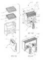
- FIGS. 1A and 1Bschematically show an exploded view and an assembled view respectively of a low inductance light source module, in accordance with embodiments of the invention
- FIG. 2schematically shows a PCB board at a stage of a production process for simultaneously producing a plurality of light source modules similar to the light source module shown in FIGS. 1A and 1B , in accordance with an embodiment of the invention
- FIGS. 3A and 3Bschematically show additional light source modules in accordance with embodiments of the invention.
- FIGS. 4A and 4Bschematically show exploded and assembled, partially cutaway views of an illumination system comprising the light source module shown in FIGS. 1A-2 coupled to a lens tube, in accordance with an embodiment of the invention
- FIG. 4Cschematically shows a cutaway view of an illumination system comprising two light source modules coupled to a same lens tube, in accordance with an embodiment of the invention.
- FIG. 5shows a schematic of a circuit for driving a light source module similar to that shown in FIGS. 1A and 1B , in accordance with an embodiment of the invention.
- FIGS. 1A and 1Bschematically show an exploded view and an assembled view respectively of a light source module 20 comprising a semiconductor light source 30 mounted to a low inductance PCB mount 40 , in accordance with an embodiment of the invention.
- light source 30is assumed to be an edge emitter laser diode from which light generated by the laser diode exits via an edge 31 of the diode.
- Laser diode 30has anode contacts 32 for electrically connecting an anode (not shown) in the laser diode to a power supply that powers the laser diode.
- a cathode (not shown) comprised in the laser diode, or an electrical contact to the cathode, for electrically connecting the power supply to the laser diodeis exposed on a side of the laser diode opposite to the side on which contacts 32 are located.
- Laser diode 30may be operable for use in a TOF-3D camera to provide short light pulses at a high repetition rate.
- PCB mount 40optionally comprises an insulating substrate 42 on a first side 43 of which are formed first and second conducting traces 44 and 45 respectively.
- mirror image conducting traces 54 and 55are formed on a second side 53 of the insulating substrate. In the perspective of FIGS. 1A and 1B only edges of minor image conducting traces 54 and 55 are shown.
- conducting traces 44 and 45are electrically connected to mirror image conducting traces 54 and 55 respectively by conducting vias 57 .
- PCB mount 40is separated from a larger PCB board along separation lines, for example by sawing or snapping, in the larger PCB board and has scalloped edges 58 resulting from holes formed in the larger PCB board to facilitate separating the PCB mount from the larger PCB board.
- first and second conducting traces 44 and 45are referred to as a cathode trace 44 and an anode trace 45 and minor image traces 54 and 55 are referred to as minor image anode and cathode traces 54 and 55 .
- Conducting traces 44 , 45 , 54 , and 55may be formed from any suitable conducting material such as copper, or silver, or copper plated with nickel, palladium or gold.
- a region 60 of cathode trace 44is reserved for bonding to laser diode 30 .
- laser diode 30is mechanically and electrically bonded to cathode trace 44 by bonding the cathode of laser diode 30 to region 60 using an electrically conducting bonding agent, such as a suitable conducting polymer or an electrically conducting epoxy.
- Region 60is schematically shown in FIG. 1A having a quantity of electrically conducting bonding material, represented by a circle 61 , for bonding the cathode of laser diode 30 and thereby the laser diode to cathode trace 44 .
- Laser diode 30is electrically connected to anode trace 45 by electrically connecting each anode contact 32 to leaf 47 of the anode trace by a bondwire 62 .
- Cathode trace 44may be formed having a recess into which at least a portion of anode trace 44 extends so that bondwires 62 that connect contacts 32 with the anode trace may be made relatively short to reduce their inductance.
- cathode 44is formed having a recess 48 for receiving a portion of anode trace 45 .
- anode trace 45is L shaped, comprising a stem 46 and a portion that extends into recess 48 in a shape of a protrusion 47 , hereinafter referred to as a “leaf” 47 , extending from the stem and into recess 48 .
- a protective cover 70may be mounted to PCB mount 40 to protect laser diode 30 and bondwires 62 .
- cover 70is formed having mounting nubs 71 that match nub recesses 72 formed in cathode and anode traces 44 and 45 .
- mounting nubs 71are inserted into nub recesses 72 to assure proper alignment of the protective cover with the PCB mount.
- laser diode 30During operation of laser diode 30 to generate light, current provided by a power supply that powers the laser diode flows into laser diode 30 along anode and mirror anode traces 44 and 45 to enter the diode via bondwires 62 and anode contacts 32 .
- the current that enters laser diode 30flows out of the laser diode via the laser diode cathode along cathode and mirror cathode traces 44 and 54 .
- Anode and cathode traces 45 and 44 and their minor traces 55 and 54are configured so that currents flowing into and out of laser diode 30 flow in substantially opposite directions and relatively close to each other to reduce inductance that the traces present to the power supply powering laser diode 30 .
- the tracesare also formed relatively wide in directions perpendicular to current flow and relatively short in directions parallel to flow of current to reduce inductance.
- Current flow into the laser diode along anode and minor anode traces 45 and 55is schematically represented by a block arrow 81 .
- Current flow out of the laser diode along cathode and mirror cathode traces 44 and 54is schematically indicated by a block arrow 82 .
- cathode trace 44 to which laser diode is directly mountedis relatively large and optionally relatively thick so that it serves as a heat sink and thermal conductor for dissipating heat generated by laser diode 30 during operation of the laser diode.
- the configuration of cathode trace 44 having a recess 48 for receiving leaf 47 of anode 45operates to extend the cathode trace laterally relative to the location of laser diode 30 on the cathode. The lateral extension tends to increase an amount of the cathode material at given distance from the laser diode and a cross section for heat transfer of the cathode trace.
- laser diode 30may be rectangular and have sides whose lengths are less than or equal to about 1 mm.
- PCB mount 40may have a height, “H”, less than or equal to about 5 mm and a width, “W”, less than or equal to about 5 mm.
- Stems 46 of anode and minor anode trace 45may have widths less than or equal to about 0.6 mm and cathode trace 44 may have width less than or equal to about 3.7 mm.
- insulating layer 42has thickness equal to or less than about 0.5 mm and conducting traces 44 , 45 , 54 and 55 may have thicknesses between about 0.1 and about 0.2 mm.
- bondwires 62 that connect anode contacts 32 to leaf 47have lengths less than or equal to about 0.75 mm.
- the bondwire lengthsare less than or equal to about 0.5 mm.
- bondwires 32have lengths less than or equal to about 0.4 mm.
- a configuration of anode and cathode traces and their minor image tracesprovide PCB mount 40 with an inductance less than or equal to about 3 nH (nanoHenrys).
- PCB mount 40is characterized by an inductance less than or equal to about 1.5 nH.
- the inductance that characterizes PCB mount 40 for the above noted dimensionsis less than conventional configurations of conductors, which are typically characterized by inductances equal to or greater than about 4 nH.
- an “effective” length of a trace 44 , 45 , 54 , and 55 , for calculating inductance of PCB mount 40is assumed to be about 3 mm less than the actual physical length of the trace.
- the effective length of a traceis a length along the trace that current travels to or from laser diode 30 from a point along the trace at which a circuit that drives laser diode 30 makes electrical contact with the trace. It is assumed that the distance from the point of electrical contact, which may for example, be a solder joint along the trace, is less than the actual length of the trace by about 3 mm.
- a light source module in accordance with an embodiment of the inventionsimilar to light source module 20 is relatively easily and inexpensively produced, and a relatively large plurality of the light sources may be simultaneously produced.
- FIG. 2schematically shows a PCB board 100 at a stage of a production process for simultaneously producing a plurality of light source modules in accordance with an embodiment of the invention similar to light source module 20 .
- PCB board 100has formed thereon a plurality of PCB mounts 20 and a laser diode 30 is bonded to cathode trace 44 of each PCB mount 40 and is electrically connected to the anode trace 45 of the PCB mount by bondwires 62 .
- a surface mount technology (SMT) pick and place machinemay have been used to bond laser diode 30 to the cathode trace.
- SMTsurface mount technology
- Bondwires 62may have been connected between anode trace 45 and anode conducting pads 32 of laser diode 30 on each PCB mount using any of various suitable automatic wire bonding processes and machines.
- Through holes 102 formed in PCB board 100 along separation lines 104facilitate separating columns of PCB mounts 40 by any of various separation processes, such as sawing, laser cutting, and/or snapping.
- protective covers 70FIGS. 1A and 1B ) have not as yet been attached to PCB mounts 20 .
- the protective coversmay be mounted PCB mounts 40 prior to separation of the PCB mounts from PCB board 100 or after separation.
- FIGS. 3A and 3Bschematically show light source modules 120 and 140 that are variations of light source module 20 shown in FIGS. 1A-1B , in accordance with embodiments of the invention.
- Light source module 120 shown in FIG. 3Ahas rectangular anode and cathode traces 121 and 122 rather than anode and cathode traces 45 and 44 having a leaf 47 and matching recess 48 respectively.
- Light source module 140 shown in FIG. 3Bcomprises a dual PCB mount 142 having two laser diodes 30 mounted to matching sets 144 of anode and cathode traces 145 and 146 formed on the PCB mount.
- light source modules 20 , 120 , and 140show a laser diode 30 located on only one side of a PCB mount
- embodiments of the inventionare not limited to light source modules having a light source on only one side of a PCB mount.
- a light source module in accordance with an embodiment of the inventionhaving a configuration of cathode and anode traces 44 and 45 and mirror traces 54 and 55 similar to that of light source module 20 ( FIG. 1B ), may also have in addition to laser diode 30 a laser diode mounted to the minor cathode 54 and connected by bondwires to minor anode 55
- FIG. 1A and 1Bschematically show light source module 20 having conducting traces 44 and 45 on a first side, 43 , of PCB mount 40 and minor image conducting traces 54 and 55 on a second side, 53 , of the PCB mount
- a light source module in accordance with an embodiment of the inventionis not limited to having traces or minor image traces on a second side of a PCB mount.
- a second side of a PCB mount comprised in a light source module in an embodimentmay have for example a single large heat sink thermally coupled by a heat conducting via to an electrically conducting trace, such as conducting trace 44 , on a first side of the PCB mount.
- a light source modulemay have formed on a second side of a PCB mount circuitry that controls a semiconductor light source mounted to traces on a first side of the PCB mount.
- At least one light source modulesuch as light source module 20 , 120 , or 140 is coupled to optics that receives and shapes light from laser diode 30 to provide an illumination system configured to provide a desire illumination pattern.
- FIGS. 4A and 4Bschematically show partially cutaway, exploded and assembled perspective views respectively of an illumination system 200 comprising light source module 20 , in accordance with an embodiment of the invention.
- Illumination system 200comprises a lens tube 202 having an optionally rectangular Fresnel collimating lens 204 seated on a ledge 206 of a recess 210 formed in the tube.
- Collimating lens 204may have a raised support edge 205 on which a rectangular diffuser 208 rests.
- Lens tube 202may, by way of example, be fabricated from a metal, such as aluminum, or high impact plastic, such as a polystyrene or polystyrene copolymer, and is formed optionally having a substantially rectangular cross section.
- Lens 204may be maintained in place on ledge 206 using any of various methods and devices known in the art.
- the lensmay be press fit into recess 210 and/or bonded by a suitable adhesive or epoxy to ledge 206 .
- Diffuser 208may be bonded to raised edge 205 and or press fit into recess 210 .
- Light source module 20seats in a recess 220 formed in lens tube 202 having a shape and depth that is matched to receive and secure the light source module with a sufficient portion 50 of the light source module protruding from lens 202 tube to enable the light source module to conveniently be plugged into a socket that provides the light source module with power.
- the recessholds light source module 20 aligned with a lumen 221 formed in the lens tube so that light, represented by a dashed arrow 36 in FIG. 4B , generated by laser diode 30 that exits the laser diode via edge 31 may propagate through the lumen to Fresnel lens 204 .
- Fresnel lens 204collimates light 36 that it receives from laser diode 30 and directs it to diffuser 208 .
- Diffuser 208optionally configures the light it receives from lens 204 into a beam of light having a desired shape.
- diffuser 208configures light it receives from lens 204 into a pyramid shaped cone beam of light whose outer envelope is schematically represented by dashed lines 230 , which numeral is also used to refer to the cone beam, to illuminate a desired field of view (FOV) (not shown).
- FOVfield of view
- cone beam 220is configured to illuminate a FOV of a 3D-TOF camera.
- an illumination systemsuch as illumination system 200
- illumination system 200may be configured having a relatively small footprint.
- illumination system 200has a height, H 200 , less than or equal to about 7.5 mm.
- H 200is less than or equal to about 5 mm.
- a maximum width, W 200 , of the illumination systemis less than or equal to about 6 mm. In some embodiments of the invention, W 200 is equal to or less than 4 mm.
- An illumination system in accordance with an embodiment of the inventionis not limited to comprising only one light source module, and may comprise a plurality of light source modules, optionally similar to light source module 20 .
- FIG. 4Cschematically shows an illumination system 250 in accordance with an embodiment of the invention comprising two light source modules 20 mounted in a lens tube 252 , optionally having a rectangular cross section.
- Illumination system 250may comprise a collimating lens 254 and diffuser 256 mounted to lens tube 252 similarly to the way in which Fresnel lens 204 and diffuser 208 are mounted in lens tube 202 shown in FIG. 4B .
- FIG. 5schematically shows illumination system 200 coupled to a circuit 300 that powers the illumination system and controls it to transmit a train of light pulses 302 characterized by pulses having pulse widths “P w ” and a repetition frequency “v”, in accordance with an embodiment of the invention.
- the pulsespropagate away from the illumination systems in cone beam 230 to illuminate a scene (not shown) toward which light system 200 is aimed.
- Circuit 300comprises a power supply 320 having a first, negative terminal 321 connected to ground and a second, positive terminal 322 connected to conducting anode trace 45 .
- Cathode trace 44is connected to a switch 326 .
- a driver 328selectively controls the switch to connect cathode trace 44 to ground or disconnect it from ground.
- switch 326connects cathode trace 44 to ground, current flows from power supply 320 through laser diode 30 and the laser diode emits light. Current ceases to flow through laser diode 30 and the laser diode stops emitting light when switch 326 disconnects conducting cathode trace 44 from ground.
- Switch 326is a switch characterized by rise and fall times that are short relative to pulse width P w , and has resistance and inductance that are relatively small in comparison to resistance and inductance contributed to circuit 300 by laser diode 30 and cathode and anode traces 45 and 45 and mirror cathode and anode traces 54 and 55 .
- Driver 328optionally controls switch 326 responsive to an input signal schematically represented by a pulse train 330 repeatedly to turn on and turn off, and thereby to connect cathode trace 44 to ground for periods having duration P w at a repetition frequency v.
- illumination system 200transmits light pulses 302 having pulse width substantially equal to P w at a repetition frequency v.
- intensity I, light pulse width P w , and transmission repetition frequency vare suitable to provide light pulses for acquiring a range image of the scene by a TOF 3D camera.
- P wis less than or equal to about 20 ns FWHM (full width half max).
- P wis less than or equal to about 15 ns.
- P wis about equal to 5 ns.
- repetition frequency vis equal to or greater than 250 kHz.
- vis greater than or equal to about 1 MHz.
- the repetition frequencyis greater than or equal to about 5 MHz.
- laser diode 30is, optionally, a laser diode marketed by OSRAM Opto Semiconductors Inc. having catalogue number SPL-PL85-3 that provides light pulses at an IR wavelength equal to about 850 nm (nanometers).
- Switch 326may be a metal-oxide- semiconductor field-effect transistor (MOSFET) such as a MOSFET marketed by Fairchild Semiconductor Corporation under the catalogue number FDMS8692.
- Switch FDMS8692has a resistance less than or equal to about 10 m ⁇ (milliohms), and an inductance less than or equal to about 0.5 nH (nanohenry).
- the switchis characterized by a switching speed between on and off (conducting and non-conducting) states having rise and fall times respectively that are less than about 3 ns (nanoseconds).
- switch 326is turned on and turned off by pulse train 330 to control the SPL-PL85-3 laser to produce light pulses 302 having pulse width P w equal to about 6 ns FWHM and repetition frequency v equal to about 0.8 MHz.
- Light pulses 302may have a peak power of about 25 watts and provide optical power at about 90 mW (milliwatts).
- power supply 320provides the illumination system with about 300 mW of electrical power.
- a conventional illumination system having inductance equal to about 4 nH and producing the same light pulses at the same repetition frequencygenerally exhibits an efficiency for converting electrical to optical energy less than about 25%.
- a configuration of conductors in accordance with an embodiment of the invention, such as that exhibited by conductors 30 and 40therefore provides an improvement in energy conversion between about 25% to about 30%.
- each of the verbs, “comprise” “include” and “have”, and conjugates thereof,are used to indicate that the object or objects of the verb are not necessarily a complete listing of components, elements or parts of the subject or subjects of the verb.
Landscapes
- Physics & Mathematics (AREA)
- General Physics & Mathematics (AREA)
- Optics & Photonics (AREA)
- Engineering & Computer Science (AREA)
- Electromagnetism (AREA)
- Condensed Matter Physics & Semiconductors (AREA)
- General Engineering & Computer Science (AREA)
- Computer Networks & Wireless Communication (AREA)
- Radar, Positioning & Navigation (AREA)
- Remote Sensing (AREA)
- Microelectronics & Electronic Packaging (AREA)
- Semiconductor Lasers (AREA)
Abstract
Description
Claims (20)
Priority Applications (2)
| Application Number | Priority Date | Filing Date | Title |
|---|---|---|---|
| US13/709,121US8882310B2 (en) | 2012-12-10 | 2012-12-10 | Laser die light source module with low inductance |
| PCT/US2013/073952WO2014093259A1 (en) | 2012-12-10 | 2013-12-09 | Laser die light source module |
Applications Claiming Priority (1)
| Application Number | Priority Date | Filing Date | Title |
|---|---|---|---|
| US13/709,121US8882310B2 (en) | 2012-12-10 | 2012-12-10 | Laser die light source module with low inductance |
Publications (2)
| Publication Number | Publication Date |
|---|---|
| US20140160745A1 US20140160745A1 (en) | 2014-06-12 |
| US8882310B2true US8882310B2 (en) | 2014-11-11 |
Family
ID=49887298
Family Applications (1)
| Application Number | Title | Priority Date | Filing Date |
|---|---|---|---|
| US13/709,121ActiveUS8882310B2 (en) | 2012-12-10 | 2012-12-10 | Laser die light source module with low inductance |
Country Status (2)
| Country | Link |
|---|---|
| US (1) | US8882310B2 (en) |
| WO (1) | WO2014093259A1 (en) |
Cited By (2)
| Publication number | Priority date | Publication date | Assignee | Title |
|---|---|---|---|---|
| US11264778B2 (en)* | 2018-11-01 | 2022-03-01 | Excelitas Canada, Inc. | Quad flat no-leads package for side emitting laser diode |
| US11611193B2 (en) | 2018-10-30 | 2023-03-21 | Excelitas Canada, Inc. | Low inductance laser driver packaging using lead-frame and thin dielectric layer mask pad definition |
Families Citing this family (11)
| Publication number | Priority date | Publication date | Assignee | Title |
|---|---|---|---|---|
| CN106461540B (en) | 2014-05-12 | 2020-02-14 | 赛洛米克斯股份有限公司 | System and method for automated imaging of chromophore-labeled samples |
| KR102149392B1 (en)* | 2015-04-10 | 2020-08-28 | 삼성전기주식회사 | Printed circuit board and manufacturing method of the same |
| DE102015116968A1 (en)* | 2015-10-06 | 2017-04-06 | Osram Opto Semiconductors Gmbh | Semiconductor laser and semiconductor laser device |
| USD822881S1 (en)* | 2016-05-31 | 2018-07-10 | Black Dog LED, LLC | Grow light |
| USD838032S1 (en)* | 2016-05-31 | 2019-01-08 | Black Dog LED, LLC. | Grow light |
| USD809702S1 (en)* | 2016-05-31 | 2018-02-06 | Black Dog LED, LLC. | Grow light |
| US10051723B2 (en) | 2016-07-29 | 2018-08-14 | Microsoft Technology Licensing, Llc | High thermal conductivity region for optoelectronic devices |
| WO2019087524A1 (en)* | 2017-11-02 | 2019-05-09 | ソニー株式会社 | Semiconductor laser drive circuit, semiconductor laser drive circuit driving method, distance measuring device and electronic machine |
| KR102629637B1 (en)* | 2018-04-19 | 2024-01-30 | 소니 세미컨덕터 솔루션즈 가부시키가이샤 | Semiconductor laser driving device and manufacturing method thereof |
| WO2020014154A1 (en)* | 2018-07-08 | 2020-01-16 | Artilux Inc. | Light emission apparatus |
| CN109149355B (en)* | 2018-09-12 | 2020-06-23 | Oppo广东移动通信有限公司 | Light emission module and control method thereof, TOF depth camera and electronic device |
Citations (191)
| Publication number | Priority date | Publication date | Assignee | Title |
|---|---|---|---|---|
| US4199703A (en) | 1978-10-04 | 1980-04-22 | Samson James A R | Low inductance, high intensity, gas discharge VUV light source |
| US4627620A (en) | 1984-12-26 | 1986-12-09 | Yang John P | Electronic athlete trainer for improving skills in reflex, speed and accuracy |
| US4630910A (en) | 1984-02-16 | 1986-12-23 | Robotic Vision Systems, Inc. | Method of measuring in three-dimensions at high speed |
| US4645458A (en) | 1985-04-15 | 1987-02-24 | Harald Phillip | Athletic evaluation and training apparatus |
| US4695953A (en) | 1983-08-25 | 1987-09-22 | Blair Preston E | TV animation interactively controlled by the viewer |
| US4702475A (en) | 1985-08-16 | 1987-10-27 | Innovating Training Products, Inc. | Sports technique and reaction training system |
| US4711543A (en) | 1986-04-14 | 1987-12-08 | Blair Preston E | TV animation interactively controlled by the viewer |
| US4751642A (en) | 1986-08-29 | 1988-06-14 | Silva John M | Interactive sports simulation system with physiological sensing and psychological conditioning |
| US4796997A (en) | 1986-05-27 | 1989-01-10 | Synthetic Vision Systems, Inc. | Method and system for high-speed, 3-D imaging of an object at a vision station |
| US4809065A (en) | 1986-12-01 | 1989-02-28 | Kabushiki Kaisha Toshiba | Interactive system and related method for displaying data to produce a three-dimensional image of an object |
| US4817950A (en) | 1987-05-08 | 1989-04-04 | Goo Paul E | Video game control unit and attitude sensor |
| US4843568A (en) | 1986-04-11 | 1989-06-27 | Krueger Myron W | Real time perception of and response to the actions of an unencumbered participant/user |
| US4893183A (en) | 1988-08-11 | 1990-01-09 | Carnegie-Mellon University | Robotic vision system |
| US4901362A (en) | 1988-08-08 | 1990-02-13 | Raytheon Company | Method of recognizing patterns |
| US4925189A (en) | 1989-01-13 | 1990-05-15 | Braeunig Thomas F | Body-mounted video game exercise device |
| DE4036896C1 (en) | 1990-11-20 | 1992-02-20 | Messerschmitt-Boelkow-Blohm Gmbh, 8012 Ottobrunn, De | Electronic current pulsing device for controlling laser diode - uses two RC-combinations and pair of heavy current switches |
| US5101444A (en) | 1990-05-18 | 1992-03-31 | Panacea, Inc. | Method and apparatus for high speed object location |
| US5148154A (en) | 1990-12-04 | 1992-09-15 | Sony Corporation Of America | Multi-dimensional user interface |
| US5168537A (en) | 1991-06-28 | 1992-12-01 | Digital Equipment Corporation | Method and apparatus for coupling light between an optoelectronic device and a waveguide |
| US5184295A (en) | 1986-05-30 | 1993-02-02 | Mann Ralph V | System and method for teaching physical skills |
| WO1993010708A1 (en) | 1991-12-03 | 1993-06-10 | French Sportech Corporation | Interactive video testing and training system |
| US5229756A (en) | 1989-02-07 | 1993-07-20 | Yamaha Corporation | Image control apparatus |
| US5229754A (en) | 1990-02-13 | 1993-07-20 | Yazaki Corporation | Automotive reflection type display apparatus |
| US5239464A (en) | 1988-08-04 | 1993-08-24 | Blair Preston E | Interactive video system providing repeated switching of multiple tracks of actions sequences |
| US5239463A (en) | 1988-08-04 | 1993-08-24 | Blair Preston E | Method and apparatus for player interaction with animated characters and objects |
| US5245620A (en)* | 1990-04-28 | 1993-09-14 | Rohm Co., Ltd. | Laser diode system for reflecting and maintaining laser light within the system |
| EP0583061A2 (en) | 1992-07-10 | 1994-02-16 | The Walt Disney Company | Method and apparatus for providing enhanced graphics in a virtual world |
| US5288078A (en) | 1988-10-14 | 1994-02-22 | David G. Capper | Control interface apparatus |
| US5295491A (en) | 1991-09-26 | 1994-03-22 | Sam Technology, Inc. | Non-invasive human neurocognitive performance capability testing method and system |
| US5320538A (en) | 1992-09-23 | 1994-06-14 | Hughes Training, Inc. | Interactive aircraft training system and method |
| US5347306A (en) | 1993-12-17 | 1994-09-13 | Mitsubishi Electric Research Laboratories, Inc. | Animated electronic meeting place |
| US5385519A (en) | 1994-04-19 | 1995-01-31 | Hsu; Chi-Hsueh | Running machine |
| US5405152A (en) | 1993-06-08 | 1995-04-11 | The Walt Disney Company | Method and apparatus for an interactive video game with physical feedback |
| US5417210A (en) | 1992-05-27 | 1995-05-23 | International Business Machines Corporation | System and method for augmentation of endoscopic surgery |
| US5423554A (en) | 1993-09-24 | 1995-06-13 | Metamedia Ventures, Inc. | Virtual reality game method and apparatus |
| US5454043A (en) | 1993-07-30 | 1995-09-26 | Mitsubishi Electric Research Laboratories, Inc. | Dynamic and static hand gesture recognition through low-level image analysis |
| US5469740A (en) | 1989-07-14 | 1995-11-28 | Impulse Technology, Inc. | Interactive video testing and training system |
| US5495576A (en) | 1993-01-11 | 1996-02-27 | Ritchey; Kurtis J. | Panoramic image based virtual reality/telepresence audio-visual system and method |
| US5516105A (en) | 1994-10-06 | 1996-05-14 | Exergame, Inc. | Acceleration activated joystick |
| US5524637A (en) | 1994-06-29 | 1996-06-11 | Erickson; Jon W. | Interactive system for measuring physiological exertion |
| US5534917A (en) | 1991-05-09 | 1996-07-09 | Very Vivid, Inc. | Video image based control system |
| US5563988A (en) | 1994-08-01 | 1996-10-08 | Massachusetts Institute Of Technology | Method and system for facilitating wireless, full-body, real-time user interaction with a digitally represented visual environment |
| US5569957A (en) | 1994-10-31 | 1996-10-29 | Harris Corporation | Low inductance conductor topography for MOSFET circuit |
| US5577981A (en) | 1994-01-19 | 1996-11-26 | Jarvik; Robert | Virtual reality exercise machine and computer controlled video system |
| US5580249A (en) | 1994-02-14 | 1996-12-03 | Sarcos Group | Apparatus for simulating mobility of a human |
| US5594469A (en) | 1995-02-21 | 1997-01-14 | Mitsubishi Electric Information Technology Center America Inc. | Hand gesture machine control system |
| US5597309A (en) | 1994-03-28 | 1997-01-28 | Riess; Thomas | Method and apparatus for treatment of gait problems associated with parkinson's disease |
| US5616078A (en) | 1993-12-28 | 1997-04-01 | Konami Co., Ltd. | Motion-controlled video entertainment system |
| US5617312A (en) | 1993-11-19 | 1997-04-01 | Hitachi, Ltd. | Computer system that enters control information by means of video camera |
| WO1997017598A1 (en) | 1995-11-06 | 1997-05-15 | Impulse Technology, Inc. | System for continuous monitoring of physical activity during unrestricted movement |
| US5638300A (en) | 1994-12-05 | 1997-06-10 | Johnson; Lee E. | Golf swing analysis system |
| US5641288A (en) | 1996-01-11 | 1997-06-24 | Zaenglein, Jr.; William G. | Shooting simulating process and training device using a virtual reality display screen |
| US5682229A (en) | 1995-04-14 | 1997-10-28 | Schwartz Electro-Optics, Inc. | Laser range camera |
| US5682196A (en) | 1995-06-22 | 1997-10-28 | Actv, Inc. | Three-dimensional (3D) video presentation system providing interactive 3D presentation with personalized audio responses for multiple viewers |
| US5690582A (en) | 1993-02-02 | 1997-11-25 | Tectrix Fitness Equipment, Inc. | Interactive exercise apparatus |
| US5703367A (en) | 1994-12-09 | 1997-12-30 | Matsushita Electric Industrial Co., Ltd. | Human occupancy detection method and system for implementing the same |
| US5704837A (en) | 1993-03-26 | 1998-01-06 | Namco Ltd. | Video game steering system causing translation, rotation and curvilinear motion on the object |
| US5715834A (en) | 1992-11-20 | 1998-02-10 | Scuola Superiore Di Studi Universitari & Di Perfezionamento S. Anna | Device for monitoring the configuration of a distal physiological unit for use, in particular, as an advanced interface for machine and computers |
| US5875108A (en) | 1991-12-23 | 1999-02-23 | Hoffberg; Steven M. | Ergonomic man-machine interface incorporating adaptive pattern recognition based control system |
| US5877803A (en) | 1997-04-07 | 1999-03-02 | Tritech Mircoelectronics International, Ltd. | 3-D image detector |
| US5913727A (en) | 1995-06-02 | 1999-06-22 | Ahdoot; Ned | Interactive movement and contact simulation game |
| US5933125A (en) | 1995-11-27 | 1999-08-03 | Cae Electronics, Ltd. | Method and apparatus for reducing instability in the display of a virtual environment |
| US5980256A (en) | 1993-10-29 | 1999-11-09 | Carmein; David E. E. | Virtual reality system with enhanced sensory apparatus |
| US5989157A (en) | 1996-08-06 | 1999-11-23 | Walton; Charles A. | Exercising system with electronic inertial game playing |
| US5995649A (en) | 1996-09-20 | 1999-11-30 | Nec Corporation | Dual-input image processor for recognizing, isolating, and displaying specific objects from the input images |
| US6005548A (en) | 1996-08-14 | 1999-12-21 | Latypov; Nurakhmed Nurislamovich | Method for tracking and displaying user's spatial position and orientation, a method for representing virtual reality for a user, and systems of embodiment of such methods |
| US6009210A (en) | 1997-03-05 | 1999-12-28 | Digital Equipment Corporation | Hands-free interface to a virtual reality environment using head tracking |
| US6054991A (en) | 1991-12-02 | 2000-04-25 | Texas Instruments Incorporated | Method of modeling player position and movement in a virtual reality system |
| US6066075A (en) | 1995-07-26 | 2000-05-23 | Poulton; Craig K. | Direct feedback controller for user interaction |
| US6072494A (en) | 1997-10-15 | 2000-06-06 | Electric Planet, Inc. | Method and apparatus for real-time gesture recognition |
| US6073489A (en) | 1995-11-06 | 2000-06-13 | French; Barry J. | Testing and training system for assessing the ability of a player to complete a task |
| US6077201A (en) | 1998-06-12 | 2000-06-20 | Cheng; Chau-Yang | Exercise bicycle |
| US6101289A (en) | 1997-10-15 | 2000-08-08 | Electric Planet, Inc. | Method and apparatus for unencumbered capture of an object |
| US6100896A (en) | 1997-03-24 | 2000-08-08 | Mitsubishi Electric Information Technology Center America, Inc. | System for designing graphical multi-participant environments |
| US6128003A (en) | 1996-12-20 | 2000-10-03 | Hitachi, Ltd. | Hand gesture recognition system and method |
| US6130677A (en) | 1997-10-15 | 2000-10-10 | Electric Planet, Inc. | Interactive computer vision system |
| US6141463A (en) | 1997-10-10 | 2000-10-31 | Electric Planet Interactive | Method and system for estimating jointed-figure configurations |
| US6147678A (en) | 1998-12-09 | 2000-11-14 | Lucent Technologies Inc. | Video hand image-three-dimensional computer interface with multiple degrees of freedom |
| US6152856A (en) | 1996-05-08 | 2000-11-28 | Real Vision Corporation | Real time simulation using position sensing |
| US6159100A (en) | 1998-04-23 | 2000-12-12 | Smith; Michael D. | Virtual reality game |
| US6173066B1 (en) | 1996-05-21 | 2001-01-09 | Cybernet Systems Corporation | Pose determination and tracking by matching 3D objects to a 2D sensor |
| US6181343B1 (en) | 1997-12-23 | 2001-01-30 | Philips Electronics North America Corp. | System and method for permitting three-dimensional navigation through a virtual reality environment using camera-based gesture inputs |
| US6188777B1 (en) | 1997-08-01 | 2001-02-13 | Interval Research Corporation | Method and apparatus for personnel detection and tracking |
| US6215898B1 (en) | 1997-04-15 | 2001-04-10 | Interval Research Corporation | Data processing system and method |
| US6215890B1 (en) | 1997-09-26 | 2001-04-10 | Matsushita Electric Industrial Co., Ltd. | Hand gesture recognizing device |
| US6226396B1 (en) | 1997-07-31 | 2001-05-01 | Nec Corporation | Object extraction method and system |
| US6229913B1 (en) | 1995-06-07 | 2001-05-08 | The Trustees Of Columbia University In The City Of New York | Apparatus and methods for determining the three-dimensional shape of an object using active illumination and relative blurring in two-images due to defocus |
| US6256400B1 (en) | 1998-09-28 | 2001-07-03 | Matsushita Electric Industrial Co., Ltd. | Method and device for segmenting hand gestures |
| US6283860B1 (en) | 1995-11-07 | 2001-09-04 | Philips Electronics North America Corp. | Method, system, and program for gesture based option selection |
| US6289112B1 (en) | 1997-08-22 | 2001-09-11 | International Business Machines Corporation | System and method for determining block direction in fingerprint images |
| US6299308B1 (en) | 1999-04-02 | 2001-10-09 | Cybernet Systems Corporation | Low-cost non-imaging eye tracker system for computer control |
| US6308565B1 (en) | 1995-11-06 | 2001-10-30 | Impulse Technology Ltd. | System and method for tracking and assessing movement skills in multidimensional space |
| US6316934B1 (en) | 1998-09-17 | 2001-11-13 | Netmor Ltd. | System for three dimensional positioning and tracking |
| US6363160B1 (en) | 1999-01-22 | 2002-03-26 | Intel Corporation | Interface using pattern recognition and tracking |
| US6384819B1 (en) | 1997-10-15 | 2002-05-07 | Electric Planet, Inc. | System and method for generating an animatable character |
| US6411744B1 (en) | 1997-10-15 | 2002-06-25 | Electric Planet, Inc. | Method and apparatus for performing a clean background subtraction |
| US6430997B1 (en) | 1995-11-06 | 2002-08-13 | Trazer Technologies, Inc. | System and method for tracking and assessing movement skills in multidimensional space |
| US6476834B1 (en) | 1999-05-28 | 2002-11-05 | International Business Machines Corporation | Dynamic creation of selectable items on surfaces |
| US6496598B1 (en) | 1997-09-02 | 2002-12-17 | Dynamic Digital Depth Research Pty. Ltd. | Image processing method and apparatus |
| US6501167B2 (en) | 2000-05-25 | 2002-12-31 | Nissan Motor Co., Ltd. | Low inductance power wiring structure and semiconductor device |
| US6503195B1 (en) | 1999-05-24 | 2003-01-07 | University Of North Carolina At Chapel Hill | Methods and systems for real-time structured light depth extraction and endoscope using real-time structured light depth extraction |
| US20030032337A1 (en) | 2001-08-13 | 2003-02-13 | Nicolaj Sorensen | Adapter for a light source |
| US20030052380A1 (en) | 2001-09-17 | 2003-03-20 | Yeo Mui Seng | Optical device carrier |
| US6539931B2 (en) | 2001-04-16 | 2003-04-01 | Koninklijke Philips Electronics N.V. | Ball throwing assistant |
| US6570555B1 (en) | 1998-12-30 | 2003-05-27 | Fuji Xerox Co., Ltd. | Method and apparatus for embodied conversational characters with multimodal input/output in an interface device |
| US6633294B1 (en) | 2000-03-09 | 2003-10-14 | Seth Rosenthal | Method and apparatus for using captured high density motion for animation |
| US6640202B1 (en) | 2000-05-25 | 2003-10-28 | International Business Machines Corporation | Elastic sensor mesh system for 3-dimensional measurement, mapping and kinematics applications |
| US6661918B1 (en) | 1998-12-04 | 2003-12-09 | Interval Research Corporation | Background estimation and segmentation based on range and color |
| US6681031B2 (en) | 1998-08-10 | 2004-01-20 | Cybernet Systems Corporation | Gesture-controlled interfaces for self-service machines and other applications |
| US6714665B1 (en) | 1994-09-02 | 2004-03-30 | Sarnoff Corporation | Fully automated iris recognition system utilizing wide and narrow fields of view |
| US6727934B2 (en) | 2001-05-31 | 2004-04-27 | Pentax Corporation | Semiconductor laser driving apparatus and laser scanner |
| US6731799B1 (en) | 2000-06-01 | 2004-05-04 | University Of Washington | Object segmentation with background extraction and moving boundary techniques |
| US6738066B1 (en) | 1999-07-30 | 2004-05-18 | Electric Plant, Inc. | System, method and article of manufacture for detecting collisions between video images generated by a camera and an object depicted on a display |
| US6778574B1 (en)* | 1999-04-05 | 2004-08-17 | Sharp Kabushiki Kaisha | Semiconductor laser device and its manufacturing method, and optical communication system and optical sensor system |
| US6788809B1 (en) | 2000-06-30 | 2004-09-07 | Intel Corporation | System and method for gesture recognition in three dimensions using stereo imaging and color vision |
| US6801637B2 (en) | 1999-08-10 | 2004-10-05 | Cybernet Systems Corporation | Optical body tracker |
| US6821128B2 (en) | 1999-09-15 | 2004-11-23 | Fci Americas Technology, Inc. | Low inductance power connector and method of reducing inductance in an electrical connector |
| US20050017488A1 (en)* | 1992-05-05 | 2005-01-27 | Breed David S. | Weight measuring systems and methods for vehicles |
| US6873723B1 (en) | 1999-06-30 | 2005-03-29 | Intel Corporation | Segmenting three-dimensional video images using stereo |
| US6937742B2 (en) | 2001-09-28 | 2005-08-30 | Bellsouth Intellectual Property Corporation | Gesture activated home appliance |
| US6950534B2 (en) | 1998-08-10 | 2005-09-27 | Cybernet Systems Corporation | Gesture-controlled interfaces for self-service machines and other applications |
| US20050280018A1 (en) | 2004-06-10 | 2005-12-22 | Citizen Electronics Co. Ltd. | Light-emitting diode |
| US7003134B1 (en) | 1999-03-08 | 2006-02-21 | Vulcan Patents Llc | Three dimensional object pose estimation which employs dense depth information |
| US7036094B1 (en) | 1998-08-10 | 2006-04-25 | Cybernet Systems Corporation | Behavior recognition system |
| US7039676B1 (en) | 2000-10-31 | 2006-05-02 | International Business Machines Corporation | Using video image analysis to automatically transmit gestures over a network in a chat or instant messaging session |
| US7042440B2 (en) | 1997-08-22 | 2006-05-09 | Pryor Timothy R | Man machine interfaces and applications |
| US7050606B2 (en) | 1999-08-10 | 2006-05-23 | Cybernet Systems Corporation | Tracking and gesture recognition system particularly suited to vehicular control applications |
| US7058204B2 (en) | 2000-10-03 | 2006-06-06 | Gesturetek, Inc. | Multiple camera control system |
| US7060957B2 (en) | 2000-04-28 | 2006-06-13 | Csem Centre Suisse D'electronique Et Microtechinique Sa | Device and method for spatially resolved photodetection and demodulation of modulated electromagnetic waves |
| US7103238B2 (en) | 2003-08-15 | 2006-09-05 | Radiantech, Inc. | COB package type bi-directional transceiver module |
| US7113918B1 (en) | 1999-08-01 | 2006-09-26 | Electric Planet, Inc. | Method for video enabled electronic commerce |
| US20060214173A1 (en) | 2005-03-28 | 2006-09-28 | Goldeneye, Inc. | Light emitting diodes and methods of fabrication |
| US7121946B2 (en) | 1998-08-10 | 2006-10-17 | Cybernet Systems Corporation | Real-time head tracking system for computer games and other applications |
| US7170492B2 (en) | 2002-05-28 | 2007-01-30 | Reactrix Systems, Inc. | Interactive video display system |
| US20070029569A1 (en) | 2005-08-04 | 2007-02-08 | Peter Andrews | Packages for semiconductor light emitting devices utilizing dispensed encapsulants and methods of packaging the same |
| US7202898B1 (en) | 1998-12-16 | 2007-04-10 | 3Dv Systems Ltd. | Self gating photosurface |
| US7222078B2 (en) | 1992-08-06 | 2007-05-22 | Ferrara Ethereal Llc | Methods and systems for gathering information from units of a commodity across a network |
| US7227526B2 (en) | 2000-07-24 | 2007-06-05 | Gesturetek, Inc. | Video-based image control system |
| US7233025B2 (en) | 2005-11-10 | 2007-06-19 | Microsoft Corporation | Electronic packaging for optical emitters and sensors |
| US7259747B2 (en) | 2001-06-05 | 2007-08-21 | Reactrix Systems, Inc. | Interactive video display system |
| US7282734B2 (en) | 2001-11-22 | 2007-10-16 | Semiconductor Energy Laboratory Co., Ltd. | Light emitting device having stripe form electrodes and auxiliary electrodes |
| US7308112B2 (en) | 2004-05-14 | 2007-12-11 | Honda Motor Co., Ltd. | Sign based human-machine interaction |
| US7306377B2 (en) | 2004-04-30 | 2007-12-11 | Finisar Corporation | Integrated optical sub-assembly having epoxy chip package |
| US7317836B2 (en) | 2005-03-17 | 2008-01-08 | Honda Motor Co., Ltd. | Pose estimation based on critical point analysis |
| US20080026838A1 (en) | 2005-08-22 | 2008-01-31 | Dunstan James E | Multi-player non-role-playing virtual world games: method for two-way interaction between participants and multi-player virtual world games |
| US7348963B2 (en) | 2002-05-28 | 2008-03-25 | Reactrix Systems, Inc. | Interactive video display system |
| US20080099770A1 (en)* | 2006-10-31 | 2008-05-01 | Medendorp Nicholas W | Integrated heat spreaders for light emitting devices (LEDs) and related assemblies |
| US7367887B2 (en) | 2000-02-18 | 2008-05-06 | Namco Bandai Games Inc. | Game apparatus, storage medium, and computer program that adjust level of game difficulty |
| US7379566B2 (en) | 2005-01-07 | 2008-05-27 | Gesturetek, Inc. | Optical flow based tilt sensor |
| US7379563B2 (en) | 2004-04-15 | 2008-05-27 | Gesturetek, Inc. | Tracking bimanual movements |
| US7388283B2 (en) | 2005-02-04 | 2008-06-17 | Avago Technologies Ecbu Ip Pte Ltd | Method and device for integrating an illumination source and detector into the same IC package that allows angular illumination with a common planar leadframe |
| US7389591B2 (en) | 2005-05-17 | 2008-06-24 | Gesturetek, Inc. | Orientation-sensitive signal output |
| US7412077B2 (en) | 2006-12-29 | 2008-08-12 | Motorola, Inc. | Apparatus and methods for head pose estimation and head gesture detection |
| US7430312B2 (en) | 2005-01-07 | 2008-09-30 | Gesturetek, Inc. | Creating 3D images of objects by illuminating with infrared patterns |
| US7436496B2 (en) | 2003-02-03 | 2008-10-14 | National University Corporation Shizuoka University | Distance image sensor |
| JP2008258296A (en) | 2007-04-03 | 2008-10-23 | Sony Corp | Light-emitting device and light source device |
| US7450736B2 (en) | 2005-10-28 | 2008-11-11 | Honda Motor Co., Ltd. | Monocular tracking of 3D human motion with a coordinated mixture of factor analyzers |
| US7452275B2 (en) | 2001-06-29 | 2008-11-18 | Konami Digital Entertainment Co., Ltd. | Game device, game controlling method and program |
| US7489812B2 (en) | 2002-06-07 | 2009-02-10 | Dynamic Digital Depth Research Pty Ltd. | Conversion and encoding techniques |
| US7536032B2 (en) | 2003-10-24 | 2009-05-19 | Reactrix Systems, Inc. | Method and system for processing captured image information in an interactive video display system |
| US7560701B2 (en) | 2005-08-12 | 2009-07-14 | Mesa Imaging Ag | Highly sensitive, fast pixel for use in an image sensor |
| US7574020B2 (en) | 2005-01-07 | 2009-08-11 | Gesturetek, Inc. | Detecting and tracking objects in images |
| US7576727B2 (en) | 2002-12-13 | 2009-08-18 | Matthew Bell | Interactive directed light/sound system |
| US7590262B2 (en) | 2003-05-29 | 2009-09-15 | Honda Motor Co., Ltd. | Visual tracking using depth data |
| US7593552B2 (en) | 2003-03-31 | 2009-09-22 | Honda Motor Co., Ltd. | Gesture recognition apparatus, gesture recognition method, and gesture recognition program |
| US7598942B2 (en) | 2005-02-08 | 2009-10-06 | Oblong Industries, Inc. | System and method for gesture based control system |
| US7607509B2 (en) | 2002-04-19 | 2009-10-27 | Iee International Electronics & Engineering S.A. | Safety device for a vehicle |
| US7620202B2 (en) | 2003-06-12 | 2009-11-17 | Honda Motor Co., Ltd. | Target orientation estimation using depth sensing |
| US20090284161A1 (en)* | 2007-12-20 | 2009-11-19 | Luminus Devices, Inc. | Light-emitting devices |
| US7684592B2 (en) | 1998-08-10 | 2010-03-23 | Cybernet Systems Corporation | Realtime object tracking system |
| US7683954B2 (en) | 2006-09-29 | 2010-03-23 | Brainvision Inc. | Solid-state image sensor |
| US7702130B2 (en) | 2004-12-20 | 2010-04-20 | Electronics And Telecommunications Research Institute | User interface apparatus using hand gesture recognition and method thereof |
| US7701439B2 (en) | 2006-07-13 | 2010-04-20 | Northrop Grumman Corporation | Gesture recognition simulation system and method |
| US7704135B2 (en) | 2004-08-23 | 2010-04-27 | Harrison Jr Shelton E | Integrated game system, method, and device |
| US7710391B2 (en) | 2002-05-28 | 2010-05-04 | Matthew Bell | Processing an image utilizing a spatially varying pattern |
| US7729530B2 (en) | 2007-03-03 | 2010-06-01 | Sergey Antonov | Method and apparatus for 3-D data input to a personal computer with a multimedia oriented operating system |
| US7728345B2 (en) | 2001-08-24 | 2010-06-01 | Cao Group, Inc. | Semiconductor light source for illuminating a physical space including a 3-dimensional lead frame |
| CN101254344B (en) | 2008-04-18 | 2010-06-16 | 李刚 | Game device of field orientation corresponding with display screen dot array in proportion and method |
| US20100207142A1 (en) | 2009-02-18 | 2010-08-19 | Chi Mei Lighting Technology Corp. | Light-emitting diode light source module |
| US20100207159A1 (en) | 2009-02-16 | 2010-08-19 | Hwan Hee Jeong | Semiconductor light emitting device |
| US7852262B2 (en) | 2007-08-16 | 2010-12-14 | Cybernet Systems Corporation | Wireless mobile indoor/outdoor tracking system |
| US7876795B2 (en) | 2004-08-19 | 2011-01-25 | Maxion Technologies, Inc. | Semiconductor light source with electrically tunable emission wavelength |
| US7878689B2 (en) | 2005-12-20 | 2011-02-01 | Industrial Technology Research Institute | Light source package structure |
| US8035612B2 (en) | 2002-05-28 | 2011-10-11 | Intellectual Ventures Holding 67 Llc | Self-contained interactive video display system |
| US8072470B2 (en) | 2003-05-29 | 2011-12-06 | Sony Computer Entertainment Inc. | System and method for providing a real-time three-dimensional interactive environment |
| US20110303941A1 (en)* | 2010-08-09 | 2011-12-15 | Lg Innotek Co., Ltd. | Light emitting device and lighting system |
| US8105854B2 (en) | 2006-02-22 | 2012-01-31 | Samsung Led Co., Ltd. | LED package |
| US20120037937A1 (en)* | 2010-08-16 | 2012-02-16 | Harvatek Corporation | Led package structure and method of making the same |
| US20120140484A1 (en) | 2010-12-01 | 2012-06-07 | Microsoft Corporation | Light source module |
| WO2012112310A1 (en) | 2011-02-18 | 2012-08-23 | 3M Innovative Properties Company | Flexible light emitting semiconductor device having thin dielectric substrate |
| US20120287646A1 (en) | 2011-05-09 | 2012-11-15 | Microsoft Corporation | Low inductance light source module |
Family Cites Families (1)
| Publication number | Priority date | Publication date | Assignee | Title |
|---|---|---|---|---|
| JP3329573B2 (en)* | 1994-04-18 | 2002-09-30 | 日亜化学工業株式会社 | LED display |
- 2012
- 2012-12-10USUS13/709,121patent/US8882310B2/enactiveActive
- 2013
- 2013-12-09WOPCT/US2013/073952patent/WO2014093259A1/enactiveApplication Filing
Patent Citations (213)
| Publication number | Priority date | Publication date | Assignee | Title |
|---|---|---|---|---|
| US4199703A (en) | 1978-10-04 | 1980-04-22 | Samson James A R | Low inductance, high intensity, gas discharge VUV light source |
| US4695953A (en) | 1983-08-25 | 1987-09-22 | Blair Preston E | TV animation interactively controlled by the viewer |
| US4630910A (en) | 1984-02-16 | 1986-12-23 | Robotic Vision Systems, Inc. | Method of measuring in three-dimensions at high speed |
| US4627620A (en) | 1984-12-26 | 1986-12-09 | Yang John P | Electronic athlete trainer for improving skills in reflex, speed and accuracy |
| US4645458A (en) | 1985-04-15 | 1987-02-24 | Harald Phillip | Athletic evaluation and training apparatus |
| US4702475A (en) | 1985-08-16 | 1987-10-27 | Innovating Training Products, Inc. | Sports technique and reaction training system |
| US4843568A (en) | 1986-04-11 | 1989-06-27 | Krueger Myron W | Real time perception of and response to the actions of an unencumbered participant/user |
| US4711543A (en) | 1986-04-14 | 1987-12-08 | Blair Preston E | TV animation interactively controlled by the viewer |
| US4796997A (en) | 1986-05-27 | 1989-01-10 | Synthetic Vision Systems, Inc. | Method and system for high-speed, 3-D imaging of an object at a vision station |
| US5184295A (en) | 1986-05-30 | 1993-02-02 | Mann Ralph V | System and method for teaching physical skills |
| US4751642A (en) | 1986-08-29 | 1988-06-14 | Silva John M | Interactive sports simulation system with physiological sensing and psychological conditioning |
| US4809065A (en) | 1986-12-01 | 1989-02-28 | Kabushiki Kaisha Toshiba | Interactive system and related method for displaying data to produce a three-dimensional image of an object |
| US4817950A (en) | 1987-05-08 | 1989-04-04 | Goo Paul E | Video game control unit and attitude sensor |
| US5239463A (en) | 1988-08-04 | 1993-08-24 | Blair Preston E | Method and apparatus for player interaction with animated characters and objects |
| US5239464A (en) | 1988-08-04 | 1993-08-24 | Blair Preston E | Interactive video system providing repeated switching of multiple tracks of actions sequences |
| US4901362A (en) | 1988-08-08 | 1990-02-13 | Raytheon Company | Method of recognizing patterns |
| US4893183A (en) | 1988-08-11 | 1990-01-09 | Carnegie-Mellon University | Robotic vision system |
| US5288078A (en) | 1988-10-14 | 1994-02-22 | David G. Capper | Control interface apparatus |
| US4925189A (en) | 1989-01-13 | 1990-05-15 | Braeunig Thomas F | Body-mounted video game exercise device |
| US5229756A (en) | 1989-02-07 | 1993-07-20 | Yamaha Corporation | Image control apparatus |
| US5469740A (en) | 1989-07-14 | 1995-11-28 | Impulse Technology, Inc. | Interactive video testing and training system |
| US5229754A (en) | 1990-02-13 | 1993-07-20 | Yazaki Corporation | Automotive reflection type display apparatus |
| US5245620A (en)* | 1990-04-28 | 1993-09-14 | Rohm Co., Ltd. | Laser diode system for reflecting and maintaining laser light within the system |
| US5101444A (en) | 1990-05-18 | 1992-03-31 | Panacea, Inc. | Method and apparatus for high speed object location |
| DE4036896C1 (en) | 1990-11-20 | 1992-02-20 | Messerschmitt-Boelkow-Blohm Gmbh, 8012 Ottobrunn, De | Electronic current pulsing device for controlling laser diode - uses two RC-combinations and pair of heavy current switches |
| US5148154A (en) | 1990-12-04 | 1992-09-15 | Sony Corporation Of America | Multi-dimensional user interface |
| US5534917A (en) | 1991-05-09 | 1996-07-09 | Very Vivid, Inc. | Video image based control system |
| US5168537A (en) | 1991-06-28 | 1992-12-01 | Digital Equipment Corporation | Method and apparatus for coupling light between an optoelectronic device and a waveguide |
| US5295491A (en) | 1991-09-26 | 1994-03-22 | Sam Technology, Inc. | Non-invasive human neurocognitive performance capability testing method and system |
| US6054991A (en) | 1991-12-02 | 2000-04-25 | Texas Instruments Incorporated | Method of modeling player position and movement in a virtual reality system |
| WO1993010708A1 (en) | 1991-12-03 | 1993-06-10 | French Sportech Corporation | Interactive video testing and training system |
| US5875108A (en) | 1991-12-23 | 1999-02-23 | Hoffberg; Steven M. | Ergonomic man-machine interface incorporating adaptive pattern recognition based control system |
| US20050017488A1 (en)* | 1992-05-05 | 2005-01-27 | Breed David S. | Weight measuring systems and methods for vehicles |
| US5417210A (en) | 1992-05-27 | 1995-05-23 | International Business Machines Corporation | System and method for augmentation of endoscopic surgery |
| EP0583061A2 (en) | 1992-07-10 | 1994-02-16 | The Walt Disney Company | Method and apparatus for providing enhanced graphics in a virtual world |
| US7222078B2 (en) | 1992-08-06 | 2007-05-22 | Ferrara Ethereal Llc | Methods and systems for gathering information from units of a commodity across a network |
| US5320538A (en) | 1992-09-23 | 1994-06-14 | Hughes Training, Inc. | Interactive aircraft training system and method |
| US5715834A (en) | 1992-11-20 | 1998-02-10 | Scuola Superiore Di Studi Universitari & Di Perfezionamento S. Anna | Device for monitoring the configuration of a distal physiological unit for use, in particular, as an advanced interface for machine and computers |
| US5495576A (en) | 1993-01-11 | 1996-02-27 | Ritchey; Kurtis J. | Panoramic image based virtual reality/telepresence audio-visual system and method |
| US5690582A (en) | 1993-02-02 | 1997-11-25 | Tectrix Fitness Equipment, Inc. | Interactive exercise apparatus |
| US5704837A (en) | 1993-03-26 | 1998-01-06 | Namco Ltd. | Video game steering system causing translation, rotation and curvilinear motion on the object |
| US5405152A (en) | 1993-06-08 | 1995-04-11 | The Walt Disney Company | Method and apparatus for an interactive video game with physical feedback |
| US5454043A (en) | 1993-07-30 | 1995-09-26 | Mitsubishi Electric Research Laboratories, Inc. | Dynamic and static hand gesture recognition through low-level image analysis |
| US5423554A (en) | 1993-09-24 | 1995-06-13 | Metamedia Ventures, Inc. | Virtual reality game method and apparatus |
| US5980256A (en) | 1993-10-29 | 1999-11-09 | Carmein; David E. E. | Virtual reality system with enhanced sensory apparatus |
| US5617312A (en) | 1993-11-19 | 1997-04-01 | Hitachi, Ltd. | Computer system that enters control information by means of video camera |
| US5347306A (en) | 1993-12-17 | 1994-09-13 | Mitsubishi Electric Research Laboratories, Inc. | Animated electronic meeting place |
| US5616078A (en) | 1993-12-28 | 1997-04-01 | Konami Co., Ltd. | Motion-controlled video entertainment system |
| US5577981A (en) | 1994-01-19 | 1996-11-26 | Jarvik; Robert | Virtual reality exercise machine and computer controlled video system |
| US5580249A (en) | 1994-02-14 | 1996-12-03 | Sarcos Group | Apparatus for simulating mobility of a human |
| US5597309A (en) | 1994-03-28 | 1997-01-28 | Riess; Thomas | Method and apparatus for treatment of gait problems associated with parkinson's disease |
| US5385519A (en) | 1994-04-19 | 1995-01-31 | Hsu; Chi-Hsueh | Running machine |
| US5524637A (en) | 1994-06-29 | 1996-06-11 | Erickson; Jon W. | Interactive system for measuring physiological exertion |
| US5563988A (en) | 1994-08-01 | 1996-10-08 | Massachusetts Institute Of Technology | Method and system for facilitating wireless, full-body, real-time user interaction with a digitally represented visual environment |
| US6714665B1 (en) | 1994-09-02 | 2004-03-30 | Sarnoff Corporation | Fully automated iris recognition system utilizing wide and narrow fields of view |
| US5516105A (en) | 1994-10-06 | 1996-05-14 | Exergame, Inc. | Acceleration activated joystick |
| US5569957A (en) | 1994-10-31 | 1996-10-29 | Harris Corporation | Low inductance conductor topography for MOSFET circuit |
| US5638300A (en) | 1994-12-05 | 1997-06-10 | Johnson; Lee E. | Golf swing analysis system |
| US5703367A (en) | 1994-12-09 | 1997-12-30 | Matsushita Electric Industrial Co., Ltd. | Human occupancy detection method and system for implementing the same |
| US5594469A (en) | 1995-02-21 | 1997-01-14 | Mitsubishi Electric Information Technology Center America Inc. | Hand gesture machine control system |
| US5682229A (en) | 1995-04-14 | 1997-10-28 | Schwartz Electro-Optics, Inc. | Laser range camera |
| US5913727A (en) | 1995-06-02 | 1999-06-22 | Ahdoot; Ned | Interactive movement and contact simulation game |
| US6229913B1 (en) | 1995-06-07 | 2001-05-08 | The Trustees Of Columbia University In The City Of New York | Apparatus and methods for determining the three-dimensional shape of an object using active illumination and relative blurring in two-images due to defocus |
| US5682196A (en) | 1995-06-22 | 1997-10-28 | Actv, Inc. | Three-dimensional (3D) video presentation system providing interactive 3D presentation with personalized audio responses for multiple viewers |
| US6066075A (en) | 1995-07-26 | 2000-05-23 | Poulton; Craig K. | Direct feedback controller for user interaction |
| US6876496B2 (en) | 1995-11-06 | 2005-04-05 | Impulse Technology Ltd. | System and method for tracking and assessing movement skills in multidimensional space |
| US7038855B2 (en) | 1995-11-06 | 2006-05-02 | Impulse Technology Ltd. | System and method for tracking and assessing movement skills in multidimensional space |
| US6308565B1 (en) | 1995-11-06 | 2001-10-30 | Impulse Technology Ltd. | System and method for tracking and assessing movement skills in multidimensional space |
| US6430997B1 (en) | 1995-11-06 | 2002-08-13 | Trazer Technologies, Inc. | System and method for tracking and assessing movement skills in multidimensional space |
| US7359121B2 (en) | 1995-11-06 | 2008-04-15 | Impulse Technology Ltd. | System and method for tracking and assessing movement skills in multidimensional space |
| US6073489A (en) | 1995-11-06 | 2000-06-13 | French; Barry J. | Testing and training system for assessing the ability of a player to complete a task |
| US6765726B2 (en) | 1995-11-06 | 2004-07-20 | Impluse Technology Ltd. | System and method for tracking and assessing movement skills in multidimensional space |
| US6098458A (en) | 1995-11-06 | 2000-08-08 | Impulse Technology, Ltd. | Testing and training system for assessing movement and agility skills without a confining field |
| WO1997017598A1 (en) | 1995-11-06 | 1997-05-15 | Impulse Technology, Inc. | System for continuous monitoring of physical activity during unrestricted movement |
| US6283860B1 (en) | 1995-11-07 | 2001-09-04 | Philips Electronics North America Corp. | Method, system, and program for gesture based option selection |
| US5933125A (en) | 1995-11-27 | 1999-08-03 | Cae Electronics, Ltd. | Method and apparatus for reducing instability in the display of a virtual environment |
| US5641288A (en) | 1996-01-11 | 1997-06-24 | Zaenglein, Jr.; William G. | Shooting simulating process and training device using a virtual reality display screen |
| US6152856A (en) | 1996-05-08 | 2000-11-28 | Real Vision Corporation | Real time simulation using position sensing |
| US6173066B1 (en) | 1996-05-21 | 2001-01-09 | Cybernet Systems Corporation | Pose determination and tracking by matching 3D objects to a 2D sensor |
| US5989157A (en) | 1996-08-06 | 1999-11-23 | Walton; Charles A. | Exercising system with electronic inertial game playing |
| US6005548A (en) | 1996-08-14 | 1999-12-21 | Latypov; Nurakhmed Nurislamovich | Method for tracking and displaying user's spatial position and orientation, a method for representing virtual reality for a user, and systems of embodiment of such methods |
| US5995649A (en) | 1996-09-20 | 1999-11-30 | Nec Corporation | Dual-input image processor for recognizing, isolating, and displaying specific objects from the input images |
| US6128003A (en) | 1996-12-20 | 2000-10-03 | Hitachi, Ltd. | Hand gesture recognition system and method |
| US6009210A (en) | 1997-03-05 | 1999-12-28 | Digital Equipment Corporation | Hands-free interface to a virtual reality environment using head tracking |
| US6100896A (en) | 1997-03-24 | 2000-08-08 | Mitsubishi Electric Information Technology Center America, Inc. | System for designing graphical multi-participant environments |
| US5877803A (en) | 1997-04-07 | 1999-03-02 | Tritech Mircoelectronics International, Ltd. | 3-D image detector |
| US6215898B1 (en) | 1997-04-15 | 2001-04-10 | Interval Research Corporation | Data processing system and method |
| US6226396B1 (en) | 1997-07-31 | 2001-05-01 | Nec Corporation | Object extraction method and system |
| US6188777B1 (en) | 1997-08-01 | 2001-02-13 | Interval Research Corporation | Method and apparatus for personnel detection and tracking |
| US7042440B2 (en) | 1997-08-22 | 2006-05-09 | Pryor Timothy R | Man machine interfaces and applications |
| US6289112B1 (en) | 1997-08-22 | 2001-09-11 | International Business Machines Corporation | System and method for determining block direction in fingerprint images |
| US6496598B1 (en) | 1997-09-02 | 2002-12-17 | Dynamic Digital Depth Research Pty. Ltd. | Image processing method and apparatus |
| US6215890B1 (en) | 1997-09-26 | 2001-04-10 | Matsushita Electric Industrial Co., Ltd. | Hand gesture recognizing device |
| US6141463A (en) | 1997-10-10 | 2000-10-31 | Electric Planet Interactive | Method and system for estimating jointed-figure configurations |
| US6411744B1 (en) | 1997-10-15 | 2002-06-25 | Electric Planet, Inc. | Method and apparatus for performing a clean background subtraction |
| US6256033B1 (en) | 1997-10-15 | 2001-07-03 | Electric Planet | Method and apparatus for real-time gesture recognition |
| US6384819B1 (en) | 1997-10-15 | 2002-05-07 | Electric Planet, Inc. | System and method for generating an animatable character |
| US6101289A (en) | 1997-10-15 | 2000-08-08 | Electric Planet, Inc. | Method and apparatus for unencumbered capture of an object |
| US6130677A (en) | 1997-10-15 | 2000-10-10 | Electric Planet, Inc. | Interactive computer vision system |
| US6072494A (en) | 1997-10-15 | 2000-06-06 | Electric Planet, Inc. | Method and apparatus for real-time gesture recognition |
| US7184048B2 (en) | 1997-10-15 | 2007-02-27 | Electric Planet, Inc. | System and method for generating an animatable character |
| USRE42256E1 (en) | 1997-10-15 | 2011-03-29 | Elet Systems L.L.C. | Method and apparatus for performing a clean background subtraction |
| US7746345B2 (en) | 1997-10-15 | 2010-06-29 | Hunter Kevin L | System and method for generating an animatable character |
| US6181343B1 (en) | 1997-12-23 | 2001-01-30 | Philips Electronics North America Corp. | System and method for permitting three-dimensional navigation through a virtual reality environment using camera-based gesture inputs |
| US6159100A (en) | 1998-04-23 | 2000-12-12 | Smith; Michael D. | Virtual reality game |
| US6077201A (en) | 1998-06-12 | 2000-06-20 | Cheng; Chau-Yang | Exercise bicycle |
| US6950534B2 (en) | 1998-08-10 | 2005-09-27 | Cybernet Systems Corporation | Gesture-controlled interfaces for self-service machines and other applications |
| US7684592B2 (en) | 1998-08-10 | 2010-03-23 | Cybernet Systems Corporation | Realtime object tracking system |
| US7121946B2 (en) | 1998-08-10 | 2006-10-17 | Cybernet Systems Corporation | Real-time head tracking system for computer games and other applications |
| US7668340B2 (en) | 1998-08-10 | 2010-02-23 | Cybernet Systems Corporation | Gesture-controlled interfaces for self-service machines and other applications |
| US7036094B1 (en) | 1998-08-10 | 2006-04-25 | Cybernet Systems Corporation | Behavior recognition system |
| US6681031B2 (en) | 1998-08-10 | 2004-01-20 | Cybernet Systems Corporation | Gesture-controlled interfaces for self-service machines and other applications |
| US7460690B2 (en) | 1998-08-10 | 2008-12-02 | Cybernet Systems Corporation | Gesture-controlled interfaces for self-service machines and other applications |
| US6316934B1 (en) | 1998-09-17 | 2001-11-13 | Netmor Ltd. | System for three dimensional positioning and tracking |
| US6256400B1 (en) | 1998-09-28 | 2001-07-03 | Matsushita Electric Industrial Co., Ltd. | Method and device for segmenting hand gestures |
| US6661918B1 (en) | 1998-12-04 | 2003-12-09 | Interval Research Corporation | Background estimation and segmentation based on range and color |
| US6147678A (en) | 1998-12-09 | 2000-11-14 | Lucent Technologies Inc. | Video hand image-three-dimensional computer interface with multiple degrees of freedom |
| US7202898B1 (en) | 1998-12-16 | 2007-04-10 | 3Dv Systems Ltd. | Self gating photosurface |
| US6570555B1 (en) | 1998-12-30 | 2003-05-27 | Fuji Xerox Co., Ltd. | Method and apparatus for embodied conversational characters with multimodal input/output in an interface device |
| US6363160B1 (en) | 1999-01-22 | 2002-03-26 | Intel Corporation | Interface using pattern recognition and tracking |
| US7003134B1 (en) | 1999-03-08 | 2006-02-21 | Vulcan Patents Llc | Three dimensional object pose estimation which employs dense depth information |
| US6299308B1 (en) | 1999-04-02 | 2001-10-09 | Cybernet Systems Corporation | Low-cost non-imaging eye tracker system for computer control |
| US6778574B1 (en)* | 1999-04-05 | 2004-08-17 | Sharp Kabushiki Kaisha | Semiconductor laser device and its manufacturing method, and optical communication system and optical sensor system |
| US6503195B1 (en) | 1999-05-24 | 2003-01-07 | University Of North Carolina At Chapel Hill | Methods and systems for real-time structured light depth extraction and endoscope using real-time structured light depth extraction |
| US6476834B1 (en) | 1999-05-28 | 2002-11-05 | International Business Machines Corporation | Dynamic creation of selectable items on surfaces |
| US6873723B1 (en) | 1999-06-30 | 2005-03-29 | Intel Corporation | Segmenting three-dimensional video images using stereo |
| US6738066B1 (en) | 1999-07-30 | 2004-05-18 | Electric Plant, Inc. | System, method and article of manufacture for detecting collisions between video images generated by a camera and an object depicted on a display |
| US7113918B1 (en) | 1999-08-01 | 2006-09-26 | Electric Planet, Inc. | Method for video enabled electronic commerce |
| US7760182B2 (en) | 1999-08-01 | 2010-07-20 | Subutai Ahmad | Method for video enabled electronic commerce |
| US6801637B2 (en) | 1999-08-10 | 2004-10-05 | Cybernet Systems Corporation | Optical body tracker |
| US7050606B2 (en) | 1999-08-10 | 2006-05-23 | Cybernet Systems Corporation | Tracking and gesture recognition system particularly suited to vehicular control applications |
| US6821128B2 (en) | 1999-09-15 | 2004-11-23 | Fci Americas Technology, Inc. | Low inductance power connector and method of reducing inductance in an electrical connector |
| US7367887B2 (en) | 2000-02-18 | 2008-05-06 | Namco Bandai Games Inc. | Game apparatus, storage medium, and computer program that adjust level of game difficulty |
| US6633294B1 (en) | 2000-03-09 | 2003-10-14 | Seth Rosenthal | Method and apparatus for using captured high density motion for animation |
| US7060957B2 (en) | 2000-04-28 | 2006-06-13 | Csem Centre Suisse D'electronique Et Microtechinique Sa | Device and method for spatially resolved photodetection and demodulation of modulated electromagnetic waves |
| US6640202B1 (en) | 2000-05-25 | 2003-10-28 | International Business Machines Corporation | Elastic sensor mesh system for 3-dimensional measurement, mapping and kinematics applications |
| US6501167B2 (en) | 2000-05-25 | 2002-12-31 | Nissan Motor Co., Ltd. | Low inductance power wiring structure and semiconductor device |
| US6731799B1 (en) | 2000-06-01 | 2004-05-04 | University Of Washington | Object segmentation with background extraction and moving boundary techniques |
| US6788809B1 (en) | 2000-06-30 | 2004-09-07 | Intel Corporation | System and method for gesture recognition in three dimensions using stereo imaging and color vision |
| US7898522B2 (en) | 2000-07-24 | 2011-03-01 | Gesturetek, Inc. | Video-based image control system |
| US7227526B2 (en) | 2000-07-24 | 2007-06-05 | Gesturetek, Inc. | Video-based image control system |
| US7555142B2 (en) | 2000-10-03 | 2009-06-30 | Gesturetek, Inc. | Multiple camera control system |
| US7421093B2 (en) | 2000-10-03 | 2008-09-02 | Gesturetek, Inc. | Multiple camera control system |
| US7058204B2 (en) | 2000-10-03 | 2006-06-06 | Gesturetek, Inc. | Multiple camera control system |
| US7039676B1 (en) | 2000-10-31 | 2006-05-02 | International Business Machines Corporation | Using video image analysis to automatically transmit gestures over a network in a chat or instant messaging session |
| US6539931B2 (en) | 2001-04-16 | 2003-04-01 | Koninklijke Philips Electronics N.V. | Ball throwing assistant |
| US6727934B2 (en) | 2001-05-31 | 2004-04-27 | Pentax Corporation | Semiconductor laser driving apparatus and laser scanner |
| US7259747B2 (en) | 2001-06-05 | 2007-08-21 | Reactrix Systems, Inc. | Interactive video display system |
| US7834846B1 (en) | 2001-06-05 | 2010-11-16 | Matthew Bell | Interactive video display system |
| US7452275B2 (en) | 2001-06-29 | 2008-11-18 | Konami Digital Entertainment Co., Ltd. | Game device, game controlling method and program |
| US20030032337A1 (en) | 2001-08-13 | 2003-02-13 | Nicolaj Sorensen | Adapter for a light source |
| US7728345B2 (en) | 2001-08-24 | 2010-06-01 | Cao Group, Inc. | Semiconductor light source for illuminating a physical space including a 3-dimensional lead frame |
| US20030052380A1 (en) | 2001-09-17 | 2003-03-20 | Yeo Mui Seng | Optical device carrier |
| US6937742B2 (en) | 2001-09-28 | 2005-08-30 | Bellsouth Intellectual Property Corporation | Gesture activated home appliance |
| US7680298B2 (en) | 2001-09-28 | 2010-03-16 | At&T Intellectual Property I, L. P. | Methods, systems, and products for gesture-activated appliances |
| US7282734B2 (en) | 2001-11-22 | 2007-10-16 | Semiconductor Energy Laboratory Co., Ltd. | Light emitting device having stripe form electrodes and auxiliary electrodes |
| US7607509B2 (en) | 2002-04-19 | 2009-10-27 | Iee International Electronics & Engineering S.A. | Safety device for a vehicle |
| US7348963B2 (en) | 2002-05-28 | 2008-03-25 | Reactrix Systems, Inc. | Interactive video display system |
| US7710391B2 (en) | 2002-05-28 | 2010-05-04 | Matthew Bell | Processing an image utilizing a spatially varying pattern |
| US7170492B2 (en) | 2002-05-28 | 2007-01-30 | Reactrix Systems, Inc. | Interactive video display system |
| US8035612B2 (en) | 2002-05-28 | 2011-10-11 | Intellectual Ventures Holding 67 Llc | Self-contained interactive video display system |
| US8035624B2 (en) | 2002-05-28 | 2011-10-11 | Intellectual Ventures Holding 67 Llc | Computer vision based touch screen |
| US8035614B2 (en) | 2002-05-28 | 2011-10-11 | Intellectual Ventures Holding 67 Llc | Interactive video window |
| US7489812B2 (en) | 2002-06-07 | 2009-02-10 | Dynamic Digital Depth Research Pty Ltd. | Conversion and encoding techniques |
| US7576727B2 (en) | 2002-12-13 | 2009-08-18 | Matthew Bell | Interactive directed light/sound system |
| US7436496B2 (en) | 2003-02-03 | 2008-10-14 | National University Corporation Shizuoka University | Distance image sensor |
| US7593552B2 (en) | 2003-03-31 | 2009-09-22 | Honda Motor Co., Ltd. | Gesture recognition apparatus, gesture recognition method, and gesture recognition program |
| US7590262B2 (en) | 2003-05-29 | 2009-09-15 | Honda Motor Co., Ltd. | Visual tracking using depth data |
| US8072470B2 (en) | 2003-05-29 | 2011-12-06 | Sony Computer Entertainment Inc. | System and method for providing a real-time three-dimensional interactive environment |
| US7620202B2 (en) | 2003-06-12 | 2009-11-17 | Honda Motor Co., Ltd. | Target orientation estimation using depth sensing |
| US7103238B2 (en) | 2003-08-15 | 2006-09-05 | Radiantech, Inc. | COB package type bi-directional transceiver module |
| US7536032B2 (en) | 2003-10-24 | 2009-05-19 | Reactrix Systems, Inc. | Method and system for processing captured image information in an interactive video display system |
| US7809167B2 (en) | 2003-10-24 | 2010-10-05 | Matthew Bell | Method and system for processing captured image information in an interactive video display system |
| US7379563B2 (en) | 2004-04-15 | 2008-05-27 | Gesturetek, Inc. | Tracking bimanual movements |
| US7306377B2 (en) | 2004-04-30 | 2007-12-11 | Finisar Corporation | Integrated optical sub-assembly having epoxy chip package |
| US7308112B2 (en) | 2004-05-14 | 2007-12-11 | Honda Motor Co., Ltd. | Sign based human-machine interaction |
| US20050280018A1 (en) | 2004-06-10 | 2005-12-22 | Citizen Electronics Co. Ltd. | Light-emitting diode |
| US7876795B2 (en) | 2004-08-19 | 2011-01-25 | Maxion Technologies, Inc. | Semiconductor light source with electrically tunable emission wavelength |
| US7704135B2 (en) | 2004-08-23 | 2010-04-27 | Harrison Jr Shelton E | Integrated game system, method, and device |
| US7702130B2 (en) | 2004-12-20 | 2010-04-20 | Electronics And Telecommunications Research Institute | User interface apparatus using hand gesture recognition and method thereof |
| US7574020B2 (en) | 2005-01-07 | 2009-08-11 | Gesturetek, Inc. | Detecting and tracking objects in images |
| US7430312B2 (en) | 2005-01-07 | 2008-09-30 | Gesturetek, Inc. | Creating 3D images of objects by illuminating with infrared patterns |
| US7570805B2 (en) | 2005-01-07 | 2009-08-04 | Gesturetek, Inc. | Creating 3D images of objects by illuminating with infrared patterns |
| US7379566B2 (en) | 2005-01-07 | 2008-05-27 | Gesturetek, Inc. | Optical flow based tilt sensor |
| US7388283B2 (en) | 2005-02-04 | 2008-06-17 | Avago Technologies Ecbu Ip Pte Ltd | Method and device for integrating an illumination source and detector into the same IC package that allows angular illumination with a common planar leadframe |
| US7598942B2 (en) | 2005-02-08 | 2009-10-06 | Oblong Industries, Inc. | System and method for gesture based control system |
| US7317836B2 (en) | 2005-03-17 | 2008-01-08 | Honda Motor Co., Ltd. | Pose estimation based on critical point analysis |
| US20060214173A1 (en) | 2005-03-28 | 2006-09-28 | Goldeneye, Inc. | Light emitting diodes and methods of fabrication |
| US7389591B2 (en) | 2005-05-17 | 2008-06-24 | Gesturetek, Inc. | Orientation-sensitive signal output |
| US20070029569A1 (en) | 2005-08-04 | 2007-02-08 | Peter Andrews | Packages for semiconductor light emitting devices utilizing dispensed encapsulants and methods of packaging the same |
| US7560701B2 (en) | 2005-08-12 | 2009-07-14 | Mesa Imaging Ag | Highly sensitive, fast pixel for use in an image sensor |
| US20080026838A1 (en) | 2005-08-22 | 2008-01-31 | Dunstan James E | Multi-player non-role-playing virtual world games: method for two-way interaction between participants and multi-player virtual world games |
| US7450736B2 (en) | 2005-10-28 | 2008-11-11 | Honda Motor Co., Ltd. | Monocular tracking of 3D human motion with a coordinated mixture of factor analyzers |
| US7233025B2 (en) | 2005-11-10 | 2007-06-19 | Microsoft Corporation | Electronic packaging for optical emitters and sensors |
| US7878689B2 (en) | 2005-12-20 | 2011-02-01 | Industrial Technology Research Institute | Light source package structure |
| US8105854B2 (en) | 2006-02-22 | 2012-01-31 | Samsung Led Co., Ltd. | LED package |
| US7701439B2 (en) | 2006-07-13 | 2010-04-20 | Northrop Grumman Corporation | Gesture recognition simulation system and method |
| US7683954B2 (en) | 2006-09-29 | 2010-03-23 | Brainvision Inc. | Solid-state image sensor |
| US20080099770A1 (en)* | 2006-10-31 | 2008-05-01 | Medendorp Nicholas W | Integrated heat spreaders for light emitting devices (LEDs) and related assemblies |
| US7412077B2 (en) | 2006-12-29 | 2008-08-12 | Motorola, Inc. | Apparatus and methods for head pose estimation and head gesture detection |
| US7729530B2 (en) | 2007-03-03 | 2010-06-01 | Sergey Antonov | Method and apparatus for 3-D data input to a personal computer with a multimedia oriented operating system |
| JP2008258296A (en) | 2007-04-03 | 2008-10-23 | Sony Corp | Light-emitting device and light source device |
| US7852262B2 (en) | 2007-08-16 | 2010-12-14 | Cybernet Systems Corporation | Wireless mobile indoor/outdoor tracking system |
| US20090284161A1 (en)* | 2007-12-20 | 2009-11-19 | Luminus Devices, Inc. | Light-emitting devices |
| CN101254344B (en) | 2008-04-18 | 2010-06-16 | 李刚 | Game device of field orientation corresponding with display screen dot array in proportion and method |
| US20100207159A1 (en) | 2009-02-16 | 2010-08-19 | Hwan Hee Jeong | Semiconductor light emitting device |
| US20100207142A1 (en) | 2009-02-18 | 2010-08-19 | Chi Mei Lighting Technology Corp. | Light-emitting diode light source module |
| US20110303941A1 (en)* | 2010-08-09 | 2011-12-15 | Lg Innotek Co., Ltd. | Light emitting device and lighting system |
| US20120037937A1 (en)* | 2010-08-16 | 2012-02-16 | Harvatek Corporation | Led package structure and method of making the same |
| US20120140484A1 (en) | 2010-12-01 | 2012-06-07 | Microsoft Corporation | Light source module |
| WO2012112310A1 (en) | 2011-02-18 | 2012-08-23 | 3M Innovative Properties Company | Flexible light emitting semiconductor device having thin dielectric substrate |
| US20120287646A1 (en) | 2011-05-09 | 2012-11-15 | Microsoft Corporation | Low inductance light source module |
| WO2012154510A2 (en) | 2011-05-09 | 2012-11-15 | Microsoft Corporation | Low inductance light source module |
Non-Patent Citations (35)
| Title |
|---|
| "Design Strategies for Stray Inductance Optimized Wire-Bond Power Modules"; Muhlfeld, Ole et al.; Institute of Power Electronics and Electrical Drives, Christian-Albrechts University of Kiel, Germany; Conference PCIM Europe 2010, pp. 244-248. |
| "Power Supply for SIRILAS-30W High Power Laser Diode SPL LG81"-Application Note; Opto Semiconductors: OSRAM Catalog: Jan. 21, 2005, pp. 1-5. |
| "Simulation and Training", 1994, Division Incorporated. |
| "Virtual High Anxiety", Tech Update, Aug. 1995, pp. 22. |
| Aggarwal et al., "Human Motion Analysis: A Review", IEEE Nonrigid and Articulated Motion Workshop, 1997, University of Texas at Austin, Austin, TX. |
| Azarbayejani et al., "Visually Controlled Graphics", Jun. 1993, vol. 15, No. 6, IEEE Transactions on Pattern Analysis and Machine Intelligence. |
| Breen et al., "Interactive Occlusion and Collusion of Real and Virtual Objects in Augmented Reality", Technical Report ECRC-95-02, 1995, European Computer-Industry Research Center GmbH, Munich, Germany. |
| Brogan et al., "Dynamically Simulated Characters in Virtual Environments", Sep./Oct. 1998, pp. 2-13, vol. 18, Issue 5, IEEE Computer Graphics and Applications. |
| Chip-On-Board LED; retrieved:Oct. 15, 2012; www.prophotonix.com/resources/Technical-Overviews/about-chip-on-board.aspx; http://www.prophotonix.com/resources/Technical-Overviews/about-chip-on-board.aspx. |
| Crisp Richard; Invensas Corp; Multi-die DRAM packaging technology drives down Ultrabook platform cost-Part 1; www.eetimes.com; May 25, 2012, 1:44 PM EDT; http://www.eetimes.com/design/memory-design/4373857/-Multi-die-DRAM-packaging-technology-drives-down-Ultrabook-platform-cost---part-1. |
| Fisher et al., "Virtual Environment Display System", ACM Workshop on Interactive 3D Graphics, Oct. 1986, Chapel Hill, NC. |
| Freeman et al., "Television Control by Hand Gestures", Dec. 1994, Mitsubishi Electric Research Laboratories, TR94-24, Caimbridge, MA. |
| Granieri et al., "Simulating Humans in VR", The British Computer Society, Oct. 1994, Academic Press. |
| Hasegawa et al., "Human-Scale Haptic Interaction with a Reactive Virtual Human in a Real-Time Physics Simulator", Jul. 2006, vol. 4, No. 3, Article 6C, ACM Computers in Entertainment, New York, NY. |
| He, "Generation of Human Body Models", Apr. 2005, University of Auckland, New Zealand. |
| Hongo et al., "Focus of Attention for Face and Hand Gesture Recognition Using Multiple Cameras", Mar. 2000, pp. 156-161, 4th IEEE International Conference on Automatic Face and Gesture Recognition, Grenoble, France. |
| International Search Report dated Mar. 13, 2014 for corresponding PCT Application No. PCT/US2013/073952, International filing date Dec. 9, 2013. |
| Isard et al., "Condensation-Conditional Density Propagation for Visual Tracking", 1998, pp. 5-28, International Journal of Computer Vision 29(1), Netherlands. |
| Kanade et al., "A Stereo Machine for Video-rate Dense Depth Mapping and Its New Applications", IEEE Computer Society Conference on Computer Vision and Pattern Recognition, 1996, pp. 196-202,The Robotics Institute, Carnegie Mellon University, Pittsburgh, PA. |
| Kohler, "Special Topics of Gesture Recognition Applied in Intelligent Home Environments", In Proceedings of the Gesture Workshop, 1998, pp. 285-296, Germany. |
| Kohler, "Technical Details and Ergonomical Aspects of Gesture Recognition applied in Intelligent Home Environments", 1997, Germany. |
| Kohler, "Vision Based Remote Control in Intelligent Home Environments", University of Erlangen-Nuremberg/Germany, 1996, pp. 147-154, Germany. |
| Livingston, "Vision-based Tracking with Dynamic Structured Light for Video See-through Augmented Reality", 1998, University of North Carolina at Chapel Hill, North Carolina, USA. |
| Miyagawa et al., "CCD-Based Range Finding Sensor", Oct. 1997, pp. 1648-1652, vol. 44 No. 10, IEEE Transactions on Electron Devices. |
| Nanostack Pulsed Laser Diode in Plastic Package, 10W Peak Power; Lead (Pb) Free Product-RoHS Compliant; from Osram website/ catalog:SPL PL85; Mar. 4, 2009, Data Sheet: http://catalog.osram-os.com/catalogue/catalogue.do?favOid=0000000200020fc100070023&act=showBookmark. |
| Pavlovic et al., "Visual Interpretation of Hand Gestures for Human-Computer Interaction: A Review", Jul. 1997, pp. 677-695, vol. 19, No. 7, IEEE Transactions on Pattern Analysis and Machine Intelligence. |
| PCT International Search Report: PCT/US2012/036385 mailed on Oct. 23, 2012. |
| Pulsed Laser Diodes; from Osram website, Osram catalog, Product Family Overview, Oct. 30, 2007: http://catalog.osram-os.com/catalogue/catalogue.do?act=showBookmark&favOid=0000000200019007001c0023. |
| Qian et al., "A Gesture-Driven Multimodal Interactive Dance System", Jun. 2004, pp. 1579-1582, IEEE International Conference on Multimedia and Expo (ICME), Taipei, Taiwan. |
| Rosenhahn et al., "Automatic Human Model Generation", 2005, pp. 41-48, University of Auckland (CITR), New Zealand. |
| Shao et al., "An Open System Architecture for a Multimedia and Multimodal User Interface", Aug. 24, 1998, Japanese Society for Rehabilitation of Persons with Disabilities (JSRPD), Japan. |
| Sheridan et al., "Virtual Reality Check", Technology Review, Oct. 1993, pp. 22-28, vol. 96, No. 7. |
| Stevens, "Flights into Virtual Reality Treating Real-World Disorders", The Washington Post, Mar. 27, 1995, Science Psychology, 2 pages. |
| Wren et al., "Pfinder: Real-Time Tracking of the Human Body", MIT Media Laboratory Perceptual Computing Section Technical Report No. 353, Jul. 1997, vol. 19, No. 7, pp. 780-785, IEEE Transactions on Pattern Analysis and Machine Intelligence, Caimbridge, MA. |
| Zhao, "Dressed Human Modeling, Detection, and Parts Localization", 2001, The Robotics Institute, Carnegie Mellon University, Pittsburgh, PA. |
Cited By (2)
| Publication number | Priority date | Publication date | Assignee | Title |
|---|---|---|---|---|
| US11611193B2 (en) | 2018-10-30 | 2023-03-21 | Excelitas Canada, Inc. | Low inductance laser driver packaging using lead-frame and thin dielectric layer mask pad definition |
| US11264778B2 (en)* | 2018-11-01 | 2022-03-01 | Excelitas Canada, Inc. | Quad flat no-leads package for side emitting laser diode |
Also Published As
| Publication number | Publication date |
|---|---|
| US20140160745A1 (en) | 2014-06-12 |
| WO2014093259A1 (en) | 2014-06-19 |
Similar Documents
| Publication | Publication Date | Title |
|---|---|---|
| US8882310B2 (en) | Laser die light source module with low inductance | |
| US8888331B2 (en) | Low inductance light source module | |
| KR102503462B1 (en) | Mounting of LED elements on a flat carrier | |
| KR101460008B1 (en) | Solderless integrated package connector and heat sink for led | |
| US6733156B2 (en) | Light-emitting diode illuminated light-emitting | |
| US11339940B2 (en) | Lighting module for automotive vehicle comprising two types of light sources | |
| US10234545B2 (en) | Light source module | |
| US20190208630A1 (en) | Laser diode chip on printed circuit board | |
| JP2022022184A (en) | Light source system | |
| US10051723B2 (en) | High thermal conductivity region for optoelectronic devices | |
| US20190189598A1 (en) | Multi-Chip Module | |
| JP2007305434A (en) | Lighting device | |
| JP2022000872A (en) | Optical semiconductor device | |
| CN112857248B (en) | Depth information camera module, projection module and preparation method thereof | |
| US11519595B2 (en) | Lighting assembly with improved thermal behaviour | |
| CN118226414A (en) | Emission module, manufacturing method of emission module and electronic equipment |
Legal Events
| Date | Code | Title | Description |
|---|---|---|---|
| AS | Assignment | Owner name:MICROSOFT CORPORATION, WASHINGTON Free format text:ASSIGNMENT OF ASSIGNORS INTEREST;ASSIGNORS:MANDELBOUM, DAVID;YAHAV, GIORA;PELLMAN, ASAF;AND OTHERS;SIGNING DATES FROM 20121205 TO 20121206;REEL/FRAME:029434/0472 | |
| STCF | Information on status: patent grant | Free format text:PATENTED CASE | |
| AS | Assignment | Owner name:MICROSOFT TECHNOLOGY LICENSING, LLC, WASHINGTON Free format text:ASSIGNMENT OF ASSIGNORS INTEREST;ASSIGNOR:MICROSOFT CORPORATION;REEL/FRAME:034747/0417 Effective date:20141014 Owner name:MICROSOFT TECHNOLOGY LICENSING, LLC, WASHINGTON Free format text:ASSIGNMENT OF ASSIGNORS INTEREST;ASSIGNOR:MICROSOFT CORPORATION;REEL/FRAME:039025/0454 Effective date:20141014 | |
| MAFP | Maintenance fee payment | Free format text:PAYMENT OF MAINTENANCE FEE, 4TH YEAR, LARGE ENTITY (ORIGINAL EVENT CODE: M1551) Year of fee payment:4 | |
| MAFP | Maintenance fee payment | Free format text:PAYMENT OF MAINTENANCE FEE, 8TH YEAR, LARGE ENTITY (ORIGINAL EVENT CODE: M1552); ENTITY STATUS OF PATENT OWNER: LARGE ENTITY Year of fee payment:8 |