US8880205B2 - Integrated multimedia signal processing system using centralized processing of signals - Google Patents
Integrated multimedia signal processing system using centralized processing of signalsDownload PDFInfo
- Publication number
- US8880205B2 US8880205B2US11/204,375US20437505AUS8880205B2US 8880205 B2US8880205 B2US 8880205B2US 20437505 AUS20437505 AUS 20437505AUS 8880205 B2US8880205 B2US 8880205B2
- Authority
- US
- United States
- Prior art keywords
- speaker
- audio
- audio signal
- digital
- reference data
- Prior art date
- Legal status (The legal status is an assumption and is not a legal conclusion. Google has not performed a legal analysis and makes no representation as to the accuracy of the status listed.)
- Expired - Fee Related
Links
Images


Classifications
- G—PHYSICS
- G11—INFORMATION STORAGE
- G11B—INFORMATION STORAGE BASED ON RELATIVE MOVEMENT BETWEEN RECORD CARRIER AND TRANSDUCER
- G11B20/00—Signal processing not specific to the method of recording or reproducing; Circuits therefor
- G11B20/10—Digital recording or reproducing
- H—ELECTRICITY
- H04—ELECTRIC COMMUNICATION TECHNIQUE
- H04S—STEREOPHONIC SYSTEMS
- H04S7/00—Indicating arrangements; Control arrangements, e.g. balance control
- H04S7/30—Control circuits for electronic adaptation of the sound field
- H04S7/307—Frequency adjustment, e.g. tone control
- G—PHYSICS
- G11—INFORMATION STORAGE
- G11B—INFORMATION STORAGE BASED ON RELATIVE MOVEMENT BETWEEN RECORD CARRIER AND TRANSDUCER
- G11B20/00—Signal processing not specific to the method of recording or reproducing; Circuits therefor
- G—PHYSICS
- G11—INFORMATION STORAGE
- G11B—INFORMATION STORAGE BASED ON RELATIVE MOVEMENT BETWEEN RECORD CARRIER AND TRANSDUCER
- G11B20/00—Signal processing not specific to the method of recording or reproducing; Circuits therefor
- G11B20/02—Analogue recording or reproducing
Definitions
- each componenthas to output signals that are compatible with these standardized interfaces. This may cause significant loss and distortion of signals between the components because of the measures taken to make components communicate with each other. Also, each component currently has a separate control device for its operation, even though they operate integrally. So the invention discloses an embodiment that provides an integrated control of all the audio/video and other entertainment operations, using a centralized processing scheme, preferably in a single box or housing.
- a home entertainment systeman integrated audio/video entertainment system, called a home entertainment system.
- Each entertainment systemrequires at least three different components, which may include: a television (TV) or a video display; a video tape recorder (VTR) or digital versatile disk (DVD) player that mainly provides video signals to the display; but also provides an audio component.
- a home entertainment systemmay additionally include a set top box, which receives audio/video signals from, for example, an antenna, a cable, or a satellite dish, and a digital video recorder (DVR) that is either a separate component or integrated in the set top box.
- DVRdigital video recorder
- TV manufacturersmake a TV as an independent, separate, stand-alone device, so that any kind of video source, whether it is a VTR, a DVD player, or a set top box, can be connected to the TV. This gives consumers a choice. Thus, TV manufacturers have to provide as many connection ports and interfaces as economically feasible. These standards are set by industry organizations, such as the International Organization for Standardization (ISO), the Institute of Electrical and Electronics Engineers (IEEE), and the National Television System Committee (NTSC).
- ISOInternational Organization for Standardization
- IEEEInstitute of Electrical and Electronics Engineers
- NTSCNational Television System Committee
- Video source equipment manufacturersalso have to provide many different types of interface terminals because they do not know which type of display device may be connected to their products, and they want to give consumers as many choices as possible. As a result, devices like VTRs and DVD players also have three or four different kinds of terminals or interfaces. Alternatively, manufacturers may only provide one kind of interface that provides widespread compatibility but sacrifices quality in doing so.
- Audio source equipment and set top box manufacturersare no exceptions, either. So if we look at these three or four different components making up a home entertainment system, each component is providing three or four different interfaces just in order to provide compatibility among the consumers' choice of equipment.
- the internal, or source, signalsmay have to be converted to output signals solely for the purpose of communicating between components even though these different components use similar internal signals for their internal processes.
- component A and component Bprocess signals in the same format internally, but these internal signals may have to be converted simply for transmitting signals between component A and component B.
- every componentneeds to convert signals from the format, in which it is originally processed, to another format for transmitting output signals. Such a conversion may cause signal loss or distortion.
- the present inventionaddresses these problems by providing a system that centrally processes audio/video and other information signals. This may eliminate unnecessary conversion of signals for communication between components, thereby preserving the characteristics of the original source signals and reproducing the purest possible source signals for delivery to end users, listeners or viewers via an output device, such as a display, speakers, or other sound reproduction systems.
- the present inventionmay also enable to eliminate duplicative installation of conversion mechanisms for generating and receiving output signals currently present in most home electronics components. Therefore, a manufacturer may provide its products either at a lower price or equipped with better devices or components at the substantially same price.
- the present inventionmay offer better performance when the source signals are all digitally coded and the output device is digitally operated.
- the present inventionprovides a cost effective high end audio video reproduction system by centrally processing the functions that are now performed separately in each of the components.
- the present inventionalso enables the user to easily generate supplemental information on the musical and video contents and to broadly share such information to enhance the enjoyment of viewing and listening experience.
- the present inventioncan be achieved by functional decomposition of the existing components and combining those functions to be processed centrally, thus minimizing digital to analog or analog to digital conversions by processing all the signals digitally.
- Human beingsdo not respond uniformly to the entire range of frequencies across the audible spectrum of sound. For example, human ears can sense small changes in sound level at a middle range of frequencies of the audible spectrum more easily than changes in sound level at a low range of frequencies. Therefore, a uniform increase in sound level, which may be measured in decibels, will not uniformly increase the loudness, as perceived by a listener, for sounds of varying frequencies that comprise audio output. This uneven distribution of loudness in audio output may distort the listening experience.
- the inventionmay separate the sounds comprising audio output by frequency range and adjust the optimal sound level for each frequency range according to human response characteristics for sound or a listener's preferences, and then use these adjustments for generating adjusted signals for driving amplifiers.
- the inventionprovides an integrated audio processing system, comprising: an audio source; a central processing unit responsive to an audio signal from the audio source; and a digital volume control module adjusting the audio signal to provide an equal-loudness level for all audio frequencies of the audio signal.
- the inventionfurther provides an integrated audio processing system that includes an audio source; a central processing unit responsive to an audio signal from the audio source; a digital volume control module adjusting the audio signal; an input device providing information regarding a listener's position to the digital volume control module; and a plurality of speakers outputting audio based on the processed audio signal.
- the digital volume control modulemay also adjust the audio signal in response to the listener position information.
- the inventionalso provides an integrated audio processing system that includes an audio source; a central processing unit responsive to an audio signal from the audio source; and a speaker coupled with the central processing unit.
- the speakertransmits a performance characteristic to the central processing unit, which is used by the central processing unit in processing the audio signal.
- FIG. 1shows a schematic block diagram for an integrated multimedia system according to an embodiment of the present invention.
- FIG. 2shows a layout of an embodiment of the present invention in a PC architecture.
- FIG. 3shows a schematic block diagram for a typical audio reproduction system.
- FIG. 4shows a schematic block diagram for a digital crossover system according to an embodiment of the present invention.
- FIG. 5shows PC switching power characteristics and an exemplary power consumption wave for sound reproduction.
- FIG. 6shows a schematic block diagram for an audio reproduction system according to an embodiment of the present invention.
- FIG. 7shows a schematic block diagram for an audio reproduction system according to another embodiment of the present invention.
- FIG. 8shows a schematic block diagram for a typical digital crossover system.
- FIG. 9shows a schematic block diagram for a typical TV set.
- FIG. 10shows a schematic block diagram describing an operation of a known video system with a typical DVD player and display.
- FIG. 11shows a schematic block diagram for a video reproduction system according to an embodiment of the present invention.
- FIG. 12shows a schematic block diagram for an automatic preference control system according to an embodiment of the present invention.
- FIG. 13shows a schematic block diagram for a media-database file sharing system according to an embodiment of the present invention.
- FIG. 14shows a frame rate adjustment to a video signal from a video source according to an embodiment of the present invention.
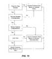
- FIG. 15is a block diagram of a method for implementing an intelligent speaker in an integrated multimedia system according to an embodiment of the present invention.
- FIG. 16is a graph showing human hearing threshold loudness levels at different sound pressure levels across the audible spectrum of sound.
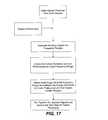
- FIG. 17is a block diagram of a method for implementing a volume control based on the loudness level for a given frequency of sound in an integrated multimedia system according to an embodiment of the present invention.
- FIG. 18is a graph showing perceived sound pressure level of different frequencies and such sound measure level with respect to the angle of a listener to audio output at zero (0) degree and at thirty (30) degrees.
- FIG. 19is a block diagram of a method for implementing a method of volume control based on a listener's position in an integrated multimedia system according to an embodiment of the present invention.
- FIG. 20is a block diagram of a digital volume control module.
- the present inventiondiscloses a system and method that may eliminate digital-analog conversions that are essential for interface compatibility among typical home electronic products.
- the present inventiontakes the most advantage of audio and video signals recorded in a digital format.
- the present inventionis not limited thereto, and can be used with traditional analog audio/video sources.
- FIG. 1shows a schematic diagram for an embodiment of the present invention.
- the integrated audio/video system 100includes a main processor 107 that receives an input signal from a signal pick-up device 103 , which acquires a source signal from a source 101 such as, for example, a video source 101 a , an audio source 101 b , or a TV tuner 101 c .
- the input signalis preferably a digital signal, but could be any type of audio/video signal, like an analog signal from a phonograph.
- the processorprocesses the input signal according to a user input 108 .
- the user inputcan be real time, such as adjusting volume or tone, or pre-set parameters. These pre-set parameters can be stored by the user on the system, or they can be generated by the system based on the system's analysis of the user's preferences based on the media viewed or listened to.
- the output signals from processor 107are also preferably digital signals.
- the signalsare processed mostly by software but the present invention is not so limited.
- a peripheral devicesuch as a specialty chip or graphic chip, can be used to process signals from the source for a specific purpose like upsampling data from an audio source or acting as a digital filter for video signals.
- the main processor 107still communicates with the peripheral devices via digital signals.
- the output signals from the main processorgo to the output devices.
- video signalsare directly sent to video display 150 .
- Modern video displayslike a Liquid Crystal Display (LCD), a Plasma Display Panel (PDP), or a Digital Light ProcessingTM (DLP) projector can take full advantage of the digital signal output from the main processor.
- LCDLiquid Crystal Display
- PDPPlasma Display Panel
- DLPDigital Light ProcessingTM
- Audio signalsmay pass through an amplifier 109 , which is preferably digital, in order to generate currents that can drive speakers.
- An embodiment of the present inventionmay use a personal computer (PC) architecture, as shown in FIG. 2 , and use a general purpose central processing unit (CPU), such as an Intel Pentium® 4 and its peripheral devices that can run widely available operating systems like, for example, Microsoft Windows® or Linux. Processing of audio and video signals may be performed in conjunction with software or peripheral hardware devices.
- the systemcan also include storage like, for example, random access memory (RAM) or a hard disk drive.
- RAMrandom access memory
- the present inventionis not limited thereto, and other processors, architectures, or operating systems may be used. Further, the present invention creates a need to develop a new operating system for controlling a home entertainment system and providing other features such as Internet access, word processing, as well as other office or work-related applications.
- An embodiment of the present inventionuses a DVD drive 101 a commonly used in most PCs for a source, or any type of optical memory drive device or optical media device, but the source could be an analog VCR source, a TV tuner, an FM/AM radio tuner, a USB port, an Internet connection, cable, satellite broadcast, digital mobile broadcast (DMB), or other sources known by those having skill in the art.
- the DVD drivemay be included in the same housing as the processor as known in a typical PC architecture.
- an amplifier for driving a speaker system(more than one speaker unit) may be included in the same housing.
- the amplifiersmay be analog and/or digital. According to one embodiment of the present invention, there may be at least one analog amplifier among this plurality of amplifiers.
- An embodiment of the present inventionmay include an LCD, PDP, or DLPTM projector as the display device 150 , any other display device that can operate in a digital mode may also be suitable. However, under certain circumstances, analog display devices may also be used.
- FIG. 3is a schematic diagram of a known audio reproduction systems.
- a source playerpicks up a source signal from various sources. For illustration, the most commonly used music source today, a compact disc (CD) player 201 will be used as the source.
- CDcompact disc
- a laser pick-up device 203reads music signals decoded on CD 201 .
- the signal read by laser pick-up device 203is a digital code, which is a combination of zeroes and ones, and the digital code is decoded by a pulse code modulator (PCM) 204 , which is a digital representation of analog data.
- PCMpulse code modulator
- the digital codeis converted into analog signals by a processor 206 that is embedded into the player or may be separately packaged.
- a pre-amplifier 208receives the analog signals and may manipulate them by adjusting their volume and tone. Signals can be manipulated either in an analog or digital format.
- a power amplifier 210receives output from pre-amplifier 208 and generates currents that can drive speakers 212 .
- Speakers 212receive the outputs from power amplifier 210 and divide the signals using internal crossover logic.
- Each of the CD player 201 , pre-amplifier 208 , and power amplifier 210includes a respective separate power source 207 , 209 , 211 .
- crossover network 214divides the signal into a high frequency range, a mid frequency range, and a low frequency range.
- the high frequency range signaldrives a tweeter 216
- the mid frequency range signaldrives a mid-range unit 218
- the low frequency range signaldrives a bass unit 220 .
- An upsampler 205may be added between source player/data pick-up device 203 and processor 206 . Upsampler 205 increases the sampling rate of conventional CD's 44.1 KHz up to 98 KHz or higher. Upsampling provides much better quality of audio sound reproduction.
- the above-described audio reproduction systemconverts an original audio digital signal into an analog signal for further processing.
- digital processingprovides more precise control of sounds and better noise reduction. Therefore, higher end audio equipment typically manipulates such signals digitally and in that case, the analog signals converted from the digital source code are converted into a digital format again. Additional signal conversion may also be necessary in the power amplifier as well as in the pre-amplifier.
- the repeated conversions of signals from analog to digital and digital to analogmay cause data loss or distortion.
- the present inventionmay solve these problems by taking the digital signals read by the laser pick-up device and having the necessary signal manipulation performed by one powerful main processor that generates speaker driving signals for a power amplifier.
- the power amplifiermay be a digital amplifier, an analog amplifier, or a combination of both.
- integrated audio/video system 100may include a digital crossover 123 , which can be implemented as a software module 115 .
- main processor 107can divide the processed audio signal into signals of speaker driving different frequency ranges and directly send the divided speaker driving signals to respective digital amplifier units 109 a of amplifier 109 , which in turn drives a speaker unit 142 , 144 , 146 of dummy speaker 140 corresponding to the frequency range of the supplied speaker driving signal.
- Digital amplifier 109may use pulse width modulation (PWM), for example, to generate the appropriate current for driving the speakers.
- PWMpulse width modulation
- amplifier 109may be a hybrid amplifier that includes an analog amplifier unit and a digital amplifier unit.
- Analog amplifiersmay be more suitable for driving high frequency speaker units such as tweeter 142
- digital amplifiersmay be more suitable for driving high power low frequency speaker units such as woofer 146 .
- Each digital driving currentprovides a speaker driving current from a respective speaker driving signal from the digital crossover module. Because the crossover may be digitally controlled by a software module, the various signal characteristics can be dynamically reconfigured.
- centrally processing the digital audio signals using a main processorenables the implementation of digital volume control, upsampling, and digital filtering, for example, by simply adding a software module.
- These processing functionscan also be achieved using peripheral hardware capable of digital signal manipulation that is coupled to the main processor.
- Digital filteringcan emulate the acoustical characteristics of the outputted audio to meet an individual listener's musical tastes, such as reproducing the characteristic of audio coming from a tube amplifier or a phonograph.
- Software based crossover logicmay provide more precise control of frequency crossover at a much lower cost. It also can provide dynamic configuration of the crossover frequencies, which together with the modules controlling other acoustical characteristics, provide optimal control of audio output.
- the present inventionmay use a PC architecture as shown in FIG. 2 .
- a new scheme of using a digital power amplifierhas been developed so that it can be used under the existing PC architecture.
- a single housing 160 having a typical front bezel 162may have disposed therein: a source such as a DVD player 101 a , a processor 107 having cooling elements like a fan 107 a and a thermal module 107 b , a system memory 164 , a hard disk drive 166 or other mass storage device, a power supply 112 and cooling fan 112 a , and expansion slots 170 .
- PCpersonal computer
- TV-Tuner 101 can amplifier 109 digital and/or analog, a digital video output card, and a variety of PC interfaces like universal serial bus (USB), Firewire (IEEE 1394), a network interface card, a variety of software control modules 115 , and a typical PC operating system like Windows®, Linux or Mac OS®, just to name a few.
- USBuniversal serial bus
- Firewire 1394Firewire
- network interface carda variety of software control modules 115
- software control modules 115a typical PC operating system like Windows®, Linux or Mac OS®, just to name a few.
- a PCwill normally shut down if it experiences a certain current power threshold level, which is shown as 10 A here.
- a typical home entertainment systemmay briefly experience current levels in excess of a PC's threshold when the amplifier generates high powered driving current, like those for certain high power bass frequencies. Accordingly, a system according to the present invention must be able to exceed a PC current threshold level when a PC architecture is used to implement an integrated multimedia processing system. Therefore, the system may provide a power tank coupled to power unit 112 to manage the spikes in current to prevent system shutdown when high powered signals are required to be driven.
- signal pick-up device 103picks up a signal from source 101 . Once the signal is picked up, the signals are computed or manipulated through processor 107 , and the final output is a digital signal or driving currents from digital amplifier 109 . If the signal comes from an analog source, it is converted into a digital signal, by a method like PCM, so that it may be processed digitally throughout the system. This conversion can be performed by main processor 107 .
- the input audio signal from source 101is fed into main processor 107 , which makes necessary computations to control volume or tone (i.e., bass or treble), or performs functions such as upsampling or other digital compensation by software emulation via modules 115 .
- the signalthen goes to digital amplifier 109 , which provides the current necessary to drive a speaker unit 142 , 144 , 146 of an appropriate frequency range based on the processed audio signal.
- the processed digital speaker driving signalcould be delivered to a digital amplifier disposed within dummy speaker 140 over a digital connection such as a USB cable or a Firewire connection, or any other suitable digital connection.
- a digital connectionsuch as a USB cable or a Firewire connection, or any other suitable digital connection.
- digital amplifier unitsfor generating current to drive the speaker units 142 , 144 , 146 .
- a feature of the present inventionis that the crossover network filtering the audio signal into different frequency ranges may be implemented within the processor, thereby eliminating the crossover network in a typical analog system comprising a set of coils, capacitors, and resistors located within a speaker.
- the analog crossover networkdoes not provide as precise separations of frequencies as the digital crossover performed by main processor 107 using software 123 as shown in FIG. 6 .
- the digital crossovermay be performed by peripheral device 138 in communication with main processor 107 as shown in FIG. 7 .
- Very expensive analog componentsare required for an analog crossover to even be comparable to a digital crossover.
- the frequency ranges provided by the digital crossover networkmay be easily adjusted such that a speaker driving signal containing the most optimal range of frequencies is delivered to a given speaker unit.
- main processor 107may send out two, three or several different kinds of speaker driving signals via respective amplifier units 109 that might be directly connected to tweeter, mid-range, or bass unit of the speaker.
- Speaker 140may also be an “intelligent” speaker having a storage device, like an integrated circuit, including performance characteristics of the speaker. Such an arrangement can be implemented in a typical home entertainment system.
- the performance characteristicscan be delivered to processor 107 for audio signal processing by either an active or passive method. In the active delivery method, the circuitry of speaker will transmit the performance characteristics to processor 107 . But in the passive method, processor 107 will query the speaker to retrieve its performance characteristics.
- performance characteristicsmay include: each unit's optimal frequency range reproduction characteristics across the audible spectrum; nominal output power; recommended amplification power; input impedance; speaker housing dimensions; sensitivity; crossover frequency; or the number of sub-speaker components.
- the speaker 140may simply include identifier information that tells system 100 what kind of speaker it is, and the processor 107 will look up the performance characteristics for the identified speaker on a table or database associated with the processor.
- processor 107can use these performance characteristics to determine the frequency ranges that match up with each speaker unit 142 , 144 , 146 of the system. These characteristics are also helpful in volume control as the system 100 can determine, for example, the sensitivity of the speaker to volume changes and a maximum speaker driving current before audio output becomes distorted.
- the arrangement of speakerscan be assisted by these performance characteristics.
- the systemcan analyze the speaker and recommend the ideal location or function for such a speaker.
- a small speaker with a low amplification powermay be ideal as a rear satellite speaker. If the bass speaker unit is most responsive to frequencies between 50 Hz and 300 Hz but is less responsive to frequencies between 300 Hz and 600 Hz, then the system can adjust its bass range between 50 Hz and 300 Hz and use a different speaker unit for producing frequencies between 300 Hz and 600 Hz. This eliminates the need for expensive speakers that can reproduce a broad spectrum of frequencies.
- Other factorscan be input to the system such as number of speakers, room size, and the desired listening experience (much like the pre-set surround settings on typical home theater receivers), just to name a few. These recommendations can be subsequently displayed on the display device.
- the advanced user who may be an audiophilecan view these characteristics on the screen and plan an optimal speaker arrangement for their tastes accordingly.
- the PC-based architecturegives the system great flexibility in providing a workable user interface for fine-tuning of the system by either the novice or the audiophile.
- FIG. 15is a block diagram illustrating one method of using such an intelligent speaker to adjust the crossover point as an example.
- the systemmay check for the new speaker.
- the systemwill request the speaker characteristics or the system will request the speaker identifier and look up the performance characteristics in response to such an identifier.
- the systemmay show these characteristics on a display device.
- the systemmay then automatically adjust the crossover point based on the speaker characteristics or may adjust the crossover in response to user input. This adjustment can then used by the system to generate a driving signal and current of an optimal frequency range for driving the speaker unit. If necessary, the user may purchase a different set of speakers or additional speakers, to take full advantage of the system.
- the systemmay recommend the speaker units needed to create the optimal litening experience based on the analysis of the system or the listener's preferences.
- FIG. 6illustrates an audio system according to an embodiment of the present invention that includes an audio source 101 like a CD player, software modules 115 coupled to processor 107 , an amplifier 109 , and a dummy speaker 140 having no crossover logic.
- the software modulesmay include: a volume control module 117 , crossover module 123 , a PCM module 126 , an upsampler module 129 , a PCM/frequency converter 131 , a digital filter 121 , a frequency/PCM converter 135 , and a communication driving module 137 .
- Crossover module 123can separate filtered digital audio signals into different frequency ranges, which are delivered to a respective frequency/PCM module 135 for each range.
- the signalsmay be converted by communication driving module 137 or delivered directly to digital amplifier 109 .
- Amplifier 109comprises a plurality of amplifier units 109 a that correspond to a given frequency range of a speaker unit 142 , 144 of dummy speaker 140 .
- FIG. 7is similar to the previously described audio system but shows that some of audio processing functions may be instead performed by peripheral hardware devices like filter 136 and crossover 138 coupled to processor 107 .
- Volume control module 117can provide further fine tuning of the audio signal by accounting for perception differences of different frequency sound at the same decibel (dB) level to provide equal loudness level for all frequencies in the processed digital audio signal.
- dBdecibel
- sounds of different frequencieshave different degrees of “loudness” at the same dB level.
- Human sensitivity to audiodepends on the frequency level of a particular sound. Generally, bass sounds are much quieter to the human ear than high frequency, or treble, sounds. While the hearing threshold between 2,000 Hz and 6,000 Hz is close to 0 dB, the hearing threshold at 125 Hz is 20 dB. Therefore, the system adjusts the audio signal so that sounds of all different frequencies are outputted by the speaker units 142 , 144 , 146 at substantially the same “loudness.” This volume control operation can be performed prior to crossover, but it is not required.
- Volume control module 117may comprise logic that incorporates the data included the graph of FIG. 16 , to provide an equal-loudness adjustment. For example, if a user requests a volume level equal to 40 phon, then volume control module 117 in conjunction with processor 107 will make an adjustment to the audio signal based on the data of the chart so that a bass sound of 125 Hz will be output at approximately 60 dB and a higher pitch sound of 6,000 Hz will be output at approximately 45 dB. When such an adjustment is made, a listener will hear both sounds as equally loud.
- the bass sound of 125 Hzshould only increase approximately 8 dB while the higher pitch sound of 6,000 Hz should increase approximately 10 dB.
- the inventioncan easily make adjustments to account for differences in the human ear's sensitivity to loudness changes for sounds of varying frequencies.
- FIG. 17shows a block diagram of a method for adjusting volume in such a manner.
- the audio signalis received by the processor from the audio source and is processed according to a requested volume control level.
- the audio signalis then separated into frequency ranges.
- the volume control moduledetermines the appropriate dB level for each frequency that corresponds to the requested volume level. This logic can also be modified by user preferences to modify the volume adjustment, say for example the user would like to hear sounds of certain frequencies somewhat louder.
- the volume control moduleperforms an audio signal adjustment to provide an equal loudness level or a user-defined loudness level.
- the adjusted audio signalmay then be further processed to generate a speaker driving signal or speaker driving current for audio output.
- These “loudness” levelscan also be modified based on user preferences so that certain types of sounds can be heard louder. For example, if a listener likes more bass, the logic can be modified so that when a 40 phon volume level is requested, the 125 HZ could be output at approximately 65 dB rather than 60 dB. These values can be modified in any manner that the listener chooses.
- audio of equal dB levelcan sound different depending on the angle of the listener.
- volume control modulecan also make an adjustment based on the position of the listener.
- FIG. 1shows input device 105 , which can be an image capture device like a camera and/or an audio input like a microphone.
- This input devicemay provide information to processor 107 and volume control module 117 about the position of the user.
- Information about the position of the speakers 140 in the roomcan be acquired via the input device or can be manually input into system 100 . Subsequently, an angle between a listener and each speaker can be determined.
- Volume control module 117having stored logic containing data for varying angles such as that for 30 degrees as illustrated in FIG. 18 , will make an adjustment to the audio signal so that the listener may experience substantially similar loudness regardless of his or her position.
- volume control module 117can make an optimal adjustment no matter the position of a speaker, including, but not limited to, in the wall, in the ceiling, sitting on a floor-stand, or sitting on a raised shelf.
- FIG. 19is a block diagram illustrating such a method for adjusting the volume based on the angle of the listener to the speakers.
- the methodis similar to the method illustrated in FIG. 17 . However, after separating the frequencies the volume control module determines any sound pressure level (dB) loss or gain resulting from the angle of the user to each speaker based on information like that contained in FIG. 18 . As before, the user may modify the dB gain or loss for certain frequencies in order to highlight certain types of audio output. The volume control module can then make an adjustment for each frequency range based on the human sensitivity of sound at an angle or user preferences. Again, the adjusted audio signal may then be further processed to generate a speaker driving signal or speaker driving current for audio output.
- dBsound pressure level
- volume control module 117may also adjust the volume of each speaker 140 based on the listener's distance from each speaker.
- FIG. 20illustrates the operation of a digital volume control module according to an embodiment of the invention.
- the audio signalmay be delivered to a frequency separator module.
- a reference data modulemay analyze the inputted audio signal and may provide information regarding the number of frequency ranges the audio signal should be separated into.
- the frequency separator modulethen separates the audio signal into a plurality of frequencies.
- the reference data modulethen supplies the appropriate reference data (e.g., human sensitivity based on frequency ranges or an angle from a sound source) corresponding to each frequency range.
- the signal adjusting modulethen makes an adjustment to the separated frequency ranges based on the supplied reference data.
- the adjusted frequency rangesare combined to generate an adjusted audio signal which is then forwarded for additional processing to generate audio output.
- the systemprovides additional digital control of audio signals thereby permitting the delivery of tailored speaker driving signals to the dummy speaker.
- dummy speakers according to an embodiment of the present inventionmay also be modified in a Lego® -like modular fashion because they are not limited by the fixed crossover frequency range logic generally contained in a typical speaker. Therefore, a user can switch out individual speaker sub-units to obtain an optimal listening experience based on that user's preferences or the type of media the user listens to.
- the present inventionalso provides another benefit by integrating all the processing and computation within a main processor. For example, by using digital filters, the present invention can provide the characteristics and feeling of the softness and warmth of tube amplifiers, or a phonograph. Also, the present invention can easily provide the functionality of an equalizer, an upscaler, or a digital crossover network.
- a digital crossover networkis sold as a separate component and one design of such a device, known as an “active” speaker 312 , is shown in FIG. 8 .
- DSPsdigital signal processors
- Each DSP 303provides signals of different frequency ranges that are delivered to a respective digital amplifier 307 , which generates driving currents for each speaker unit 310 .
- the present inventioncan implement these functions in one processor, which may have a PC architecture disposed therein, without adding expensive equipment. Furthermore, by adopting such architecture, the present invention allows dynamic adjustment of frequency levels.
- the present inventionenables user to adjust the frequency levels to whatever level whenever he or she wants to, by simply entering the ranges through the conventional input device, or automatically as programmed before.
- the typical digital crossover networkdoes not provide such features and convenience of use.
- FIG. 9shows a schematic block diagram of a typical analog TV display
- FIG. 10shows a schematic block diagram of a known DVD display configuration.
- Signals selected by a tuner 401which is a composite signal, go through a filter such as a 3D comb filter 405 to produce a luminance signal (Y-signal) and a color signal (C-signal).
- a composite signalmay also come from a composite input 402 of another video source such as a VTR.
- the Y-signal and the C-signalpass through a second filter 409 for ghost reduction and noise reduction.
- the C-signalthen goes through a color separation filter 413 to generate a blue signal (U-signal) and a red signal (V-signal).
- the U-signal and the V-signal together with the Y-signalform a component signal having YUV data in a conversion filter 417 . Images are displayed using an RGB signal from the YUV data.
- the signaldoes not need to pass through either comb filter 405 or second filter 409 because the Y-signal and C-signal are kept separate.
- DVDmay contain YUV data in a 720 ⁇ 480 format.
- Digital TVbroadcasts YUV data encoded using MPEG 2 protocol.
- Digital TVmay have different formats such as, for example, 1080i, 720p and 480p.
- Digital video sourcesalso may provide different interface protocols such as component video (Y Pb Pr), high-definition multimedia interface (HDMI), and digital video interface (DVI).
- Y Pb Prcomponent video
- HDMIhigh-definition multimedia interface
- DVIdigital video interface
- a component video interface 414keeps the Y-signal, the U-signal, and the V-signal separate such that the video signal can be delivered directly to conversion filter 417 .
- Output source signals from digital interfaces like DVI or HDMI 418 for a digital display 440can be input directly to the de-interlacer scaler 419 and do not need to pass through any of the filters that may be required for an analog display 430 .
- a digital display 440only needs additional signal filtering to be compatible with analog interfaces, even though the original source may be digital, like a DVD or digital TV.
- DVD player 420includes a pickup device 421 , a demux 422 , a video decoder 423 , a video scaler and enhancer 425 , a video encoder 427 for processing a video signal.
- DVD player 420further comprises an audio decoder 424 and a digital/analog converter 426 for providing analog audio signals, and a Sony/Phillips Digital Interface Format (SPDIF) driver 428 for providing digital audio signals.
- SPDIFSony/Phillips Digital Interface Format
- Display device 440includes a tuner 441 , video decoder 442 , de-interlacer 445 , a scaler 447 , a display driver 449 , and a display apparatus 450 for displaying video signals. Moreover, display device 440 includes an audio decoder 444 , an amplifier 448 , and a speaker 451 for providing audio. Both DVD player 420 and display device 440 include a respective power supply 429 , 452 . It is apparent to a person having ordinary skill in the art that there are many redundancies in the functions of the DVD player 420 and display device 440 , which is in part caused by the requirement to convert audio/video signals to allow signal communication between these components.
- a DVD player 420may have a digital interface like DVI or HDMI
- the additional processing components in display device 440are still needed because the DVD player cannot dynamically adapt for the resolution of the display and the display is required to be compatible for a wide range of non-digital interfaces.
- many display devicesprovide at least three different interface terminals. In some cases, they provide five different terminals. Video source players often provide many different terminals as well. These interfaces are both analog and digital.
- each video source player and each video displayhas its own converter that can convert signals coming through different interfaces into YUV data.
- the displaymay include many image filters as described above for processing the analog signals from many different interfaces into YUV data for display.
- a digital video displayrequires an additional processing step for image display.
- Modem video displayssuch as an LCD, a PDP or a DLPTM projector, have a native resolution, for example, 1920 ⁇ 1080, 1280 ⁇ 720 or 865 ⁇ 480. These resolutions are fixed when the displays are manufactured, because they have a maximum number of lines and a maximum number of pixels per line.
- a digital display devicereceives a video source signal, it has to resize, or scale, the signal to make it fit for the panel size using de-interlacer/scaler 419 .
- FIG. 11shows that the present invention, however, can perform such resizing using main processor 107 coupled to software modules 115 .
- Other compensation and manipulation of the video signalscan be also performed in the main processor, which may be coupled to a variety of software modules, including: a demux 116 , a video decoder 124 , a de-interlacer 125 , a scaler and enhancer 127 , an audio decoder 120 , and audio filter or processor 121 .
- main processor 107uses software modules 115 to process the signal from source 101 , which can be digital or analog. Signal processing can also be performed, however, by peripheral hardware devices coupled to processor 107 .
- the processed audio/video signalsare delivered to a DVI transmitter 111 and a plurality of amplifier units of amplifier 109 . If amplifier is analog or a digital/analog hybrid, a conversion of the digital signals can be performed by audio processor 121 or in amplifier 109 itself.
- the processed video signalsare sent to a dummy display 150 that may comprise simply a display driver 151 , a power supply 153 , and a digital display device 155 .
- the amplified audio signalsare sent to dummy speaker 140 in a similar manner as described above.
- the displaycan be easily upgraded by adding a new software plug-in, thereby enhancing both display quality and function.
- main processor 107can perform most of a conventional TV's functions, such as, for example, tuning, filtering, signal selecting, de-interlacing, and resizing.
- the present inventioncan digitally capture the composite signal and perform all the filtering operations to generate YUV/RGB signals for display using software modules plugged in to main processor 107 , or peripheral devices associated therewith. Therefore, by digitally processing even the typical analog TV signals, most of the analog components may be eliminated to substantially reduce the signal loss and distortion caused by the signal conversion.
- An embodiment of the present inventioncan perform most of these signal conversions in one central place. It can also detect whether the TV signals received are analog or digital. It may detect the characteristics and properties of the display device connected to the system. All the manipulations of the digital data may be performed within the main processor 107 using software modules 115 . However, if necessary, the main processor may comprise more than one physical chip. It may include another CPU or other periphery chips. A benefit of the present invention is that unnecessary conversions from digital to analog or analog to digital may be reduced or eliminated.
- the systemcan control video properties like, for example, brightness, contrast, color warmth and display resolution. Users can control these properties manually as well as automatically using optimization parameters. Users can generate such parameters by themselves or acquire these parameters from either other users or a content provider.
- the processorcan resize the display signal so that it is appropriate for the display resolution. Lower resolution signals, however, are difficult to view on larger screens because the flaws in these low resolutions signals are easy to see on larger screens. This is especially problematic when using an overhead DLPTM projector on a screen of 72 inches (6 feet) or greater that are now used in many home-theater systems. It is the same for a large size flat panel displays, such as, for example, a 102-inch PDP or 80-inch LCD. Accordingly, the processor can make adjustments to these lower-resolution signals so that they display more clearly on large screens. Such an arrangement, will allow many home-theater users to view standard definition programs as well as high-definition programs on their systems.
- the systemcan also make an adjustment of the display frame rate to take full advantage of the display capabilities of modem digital display devices.
- the movies recorded on DVDhave a frame rate of 24 frames per second (fps), and NTSC DVD specifications call for a refresh rate of approximately 30 fps.
- modem digital displaysare capable of display refresh rates of greater than 72 Hz, which translate to 36 fps or more. Therefore, the system can generate intermediate frames based on analysis of two adjacent frames to increase the number frames per second displayed on the digital display of a higher refresh rate.
- the systemcan also make adjustments based on the motion in a scene displayed from the video source and make an adjustment accordingly, including a higher frame rate.
- one (1) inch on a 32-inch displaycan correspond to approximately four (4) inches on a 120-inch display. Therefore, a user may notice an interruption on the 120-inch display, which he or she may have not noticed on the 32-inch display.
- the present inventioncan provide a solution.
- conventional movies with a frame rate of 24 fps recorded onto DVDare subsequently played on a modem digital display, which is capable of a display refresh rate of greater than 72 Hz, typical methods show duplicate scenes for the extra frames.
- a display with a 72 Hz refresh ratemay show an extra two (2) frames in addition to the original frames of 24 fps movies.
- the conventional methodshows the same (n) th scene on the (n)′ th frame and the (n)′′ th frame.
- the sameis true for (n+1) th frame as the (n+1)′ th frame and the (n+1)′′ th frame both display the same (n+1) th scene.
- the present inventionmay allocate weights for each additional frame.
- the (n)′ th framemay be a composition of 65% of (n) th frame and 35% of (n+1) th frame.
- the (n)′′ th framemay be a composition of 35% of the (n) th frame and 65% of (n+1) th frame.
- the (n+1) th frame groupis adjusted similarly.
- the (n+1)′ th framecomprises 65% of the (n+1) th frame and 35% of the (n+2) th frame.
- the (n+1)′′ th framecomprises 35% of the (n+1) th frame and 65% of the (n+2) th frame.
- n′n *0.65+( n+ 1)*0.35
- n′′n* 0.35+( n+ 1)*0.65
- weights for each additional frameviewers can appreciate better quality of video display.
- the weights shown heresuch as 65% and 35% are arbitrary numbers for illustrative purposes only and may vary depending on the purposes of frame rate compensations, characteristics of the scene, tastes of the viewer, viewing environment and other factors, and should not be construed as being limited to these factors.
- source 101is an RF tuner that picks up a certain channel from the RF signal
- those composite signalsare digitized through a demodulator (not shown) at once, which can be a software module 115 or a peripheral device coupled to processor 107 , and the converted digital signals are manipulated through the CPU without going through filters or other upscalers. Therefore, the final output signal is just nothing but a digital RGB signal which can be input to the digital display device 150 , such as PDP, LCD or DLP screen displays.
- set-top box functionslike tuning and decoding of cable, satellite, or antenna signals can be performed within the system.
- a signal sourcemay be directly connected to the system, which then performs the necessary functions to deliver the appropriate signals for processing so that they can be viewed or heard.
- Centralized processing of multimedia signalsprovided by the present invention allows simplification of each device's hardware configuration by eliminating redundant processing and unnecessary signal conversions, thereby lowering manufacturing costs.
- Centralized processingcan also provide digital processing of signals from the source to the last-end and provide high quality image and audio signals with superior control.
- the present inventionprovides integrated and centralized processing of audio signals, video signals, and other information signals, enabling the elimination of unnecessary signal conversions when signals are sent to different components by functional decomposition of the conventional components.
- a typical DVDcontains YUV data using MPEG2 compression and has a 480i ⁇ 60 field format.
- a conventional DVD playerfirst decompresses the signal read by the laser pick-up device.
- the decompressed YUV datais then processed depending on the display to be used.
- Such a processmay include, but is not limited to, conversions to composite signals for an analog TV or a VTR, de-interlacing for non-interlaced display device, resizing for the appropriate screen resolution, and color enhancing. Details of these processes are well known in the art and one of ordinary skill would know the kinds and methods of signal conversions necessary for displaying different video signals.
- the present inventioncan perform all these processes in main processor 107 . Therefore, the preferred embodiment of present invention may substantially reduce product costs by eliminating signal processing devices from each of the components (TV, VTR and DVD player). At the same time, the overall performance is improved by utilizing much more powerful processor for signal processing than the conventional parts used in the individual TV or DVD player. These advantages of the present invention are better realized by utilizing digitally coded video and audio sources with a display that can be digitally operated pixel by pixel.
- a DVDcontains video signals using an MPEG-2 decoding protocol and the format is 480i ⁇ 60 fields per second.
- 240 odd line signalsare displayed for 30 fields and 240 even line signals are displayed for the other 30 fields.
- the odd and even linesare alternately displayed to form a whole image.
- High definition display devicescan provide much better resolution than the DVD's inherent resolution.
- One wayis to pick up the 480i signal from the source pickup device and de-interlace those signals. Then it doubles the scan lines and sends a signal of 480p ⁇ 60 fields to the display device. That is what we usually call a progressive scan, which means that all 480 lines are displayed at the same time.
- HD-Q DVDdoes more than this. It resizes the 480 line signal into a 720 line signal, and then does a progressive scan. Such a resizing and progressive scan can be done in a video source player, such as DVD player or in the display itself.
- the present inventionenables such functions as de-interlacing and resizing (i.e., scaling) to be performed in main processor 107 . All of these functions that are performed by different components may be implemented in main processor 107 . This prevents redundant investment in different components and by saving those resources, we can extract better quality or much enhanced display performance with the same or even less resources.
- the present inventionfirst processes and then outputs them to the digital display device, such as LCD, PDP or DLPTM projection TV.
- the digital display devicesuch as LCD, PDP or DLPTM projection TV.
- the digital display devicesuch as LCD, PDP or DLPTM projection TV.
- the present inventionprovides a flexible architecture that allows the system to efficiently adapt to the components attached to the processor box.
- the video displaymay have to convert the signal depending on the native resolution of the display device.
- the video sourceoutputs a high resolution signal of 1920 ⁇ 1080 format
- the display's native resolutiondoes not meet such a high resolution
- the video displaywill need to resize the high resolution signal down to 1280 ⁇ 720 or 865 ⁇ 480 format for it to be displayed according to the display's resolution. This requires additional unnecessary signal conversions, which may degrade signal quality and, thus, image quality.
- the present inventionmay resolve these problems, taking advantage of its flexible architecture to use main processor 107 for converting the signal to a format that exactly matches the display's native resolution.
- the systemmay detect the size, the resolution or other characteristics of the display, either by user input or by communication with the connected display. In the latter case, the display may forward its display characteristics to the system's main processor upon request.
- Main processor 107can output 1920 ⁇ 1080 high resolution signal if the attached display can support such a high resolution. If the attached display only support up to 865 ⁇ 480 resolution, then main processor 107 can easily convert the video signals to that format and send them to the display. Accordingly, the present invention can provide signals that may exactly fit any given display device because all the output signals are processed by a main processor using software, rather than through physically separated and dedicated conversion chips or circuits.
- a display devicemay need higher-end optical elements, like lenses, light sources, mirrors, front glass plates, and sensors, for example, to provide a true high-definition display. Otherwise, abnormalities in these elements can degrade the quality of the image output.
- U.S. Patent Application Publication 2004/076336describes a method for “warping” the image so that a corrective effect to overcome these abnormalities in either an image capture or image display device can be achieved.
- a processoris used in either the capture device or display device itself.
- main processor 107can be used to make these corrective adjustments to the video signals.
- the main processorcan perform such adjustments through software or with the assistance of a special peripheral circuitry, like the Silicon Optix sxW1-LX chip.
- a special peripheral circuitrylike the Silicon Optix sxW1-LX chip.
- DLPTM rear projectorsalso pose a special problem for digital displays because, unlike PDP and LCD displays, they are not flat and can take up a lot of room for larger display sizes.
- a rear projection DLPTM displayan image projector projects an image onto a mirror at the back of the display case, which reflects the image onto the screen for viewing.
- DLPTM rear projection displayswere relatively bulky as compared to other digital display types.
- a curved mirrorwas implemented to reduce the projection distance needed for achieving a larger display.
- Another typical way of reducing the projection distanceis to reflect the image off of more than one mirror, which may also be disposed at a wide angle as compared to the viewing angle.
- the images displayed by these alternatively configured rear projection DLPTM rear projection displaysoften are distorted.
- U.S. Patent Application Publication 2003/0231261addresses these problems by “pre-distorting” the image in a manner that uses the distortion caused by the DLPTM display's configuration to display an image correctly.
- the present inventionobviates the need to provide such pre-distortion in the display itself. Rather, this distortion may be performed by main processor 107 so that an embodiment of the present invention may use an integrated multimedia processing system with a dummy DLPTM rear projection display having a reduced projection distance requirement.
- Such a pre-adjustment of images that can be achieved by the present inventionis not limited to a rear-projection display.
- the present inventioncan make pre-adjustments for the correct display of images based on the properties and characteristics of lenses and other optical equipment. Therefore, high-end components and lenses, which greatly increase a display's cost, may not be required to achieve a high quality image display.
- All the information on the display characteristicscan be stored in the display and can be fetched by the main processor of the system when necessary.
- the present inventionfinally integrates audio, video, Internet, and media storage in one functional device, taking advantage of developments in digital audio/video sources and digital display devices.
- digital audio/video sourcesand digital display devices.
- the system and method of the present inventionthat takes advantage of digital audio/video source and recently developed digital video displays to provide a higher quality audio and video experience.
- the aspects of the present invention with respect to the Internet and storage functionswill now be described.
- a storage devicemay be included with the integrated multimedia processing system that can facilitate dynamic customization of the system depending on the audio or video source.
- a storage devicemay be included with the integrated multimedia processing system that can facilitate dynamic customization of the system depending on the audio or video source.
- FIG. 12shows a mass storage device 501 in communication with main processor 107 of system 100 .
- Mass storage devicecan be coupled externally or internally to integrated audio/video system 100 and include a database 503 for storing media characteristics.
- a signal recognition module 505which can be a software module coupled to processor 107 , may be included.
- Other software modules 115may include: an archiving system 510 that archives content in storage device 501 ; an information gathering system 515 for analyzing stored off-line content in conjunction with the archiving system 510 or real time content in conjunction with signal recognition module 505 for use in database 503 ; and information fetching system 520 for retrieving analyzed content characteristics from database 503 .
- Signal recognition module 505can recognize certain types of signals that may be specific to the type of audio presented or the type of image displayed. For example, certain audio signal characteristics may be associated with an optimal presentation of jazz music, or certain video signals may be associated with an optimal display of kinetic scenes in action movies. The advantages of providing a signal recognition module, or other similar feedback and control mechanism, are described in detail below.
- a home entertainment systemoutputs audio and video signals on a real time basis as users normally do not operate the system unless, for example, they wish to hear music or watch a movie at that time.
- usersFor real time play, users have to load the sources, CDs or DVDs, on the player whenever they want to enjoy them.
- Jukeboxesare available to physically aggregate many music sources (CDs or LPs) and DVDs in one place for a user to select desired media.
- mass storage device 501can be a storage device contained in a box, like a hard disk in a PC, an external device, or the Internet. It is not limited thereto and any future development of mass storage device as well as their equivalents can be used. Mass storage device 501 can be connected through any suitable communication method, such as the Internet, USB, or Firewire, for example.
- storage device 501may contain a string concerto media file.
- Processor 107using information gathering software, for example, can perform off-line analysis of the string concerto stored in the hard disk.
- the computercan analyze the audio source, when the music is not played, and can tag the string music as a high frequency audio source, the vocals as a mid frequency audio source, and the percussion as a low frequency audio source.
- This analysiscan be performed by main processor 107 or other information gathering system 515 in conjunction with archiving system 510 while the music is not played.
- main processor 107 or other information gathering system 515in conjunction with archiving system 510 while the music is not played.
- the processormay automatically adjust the crossover for the high frequency range from 2 KHz to 1.7 KHz based on the off-line analysis. This may produce much better sound by increasing the tweeter range for a violin.
- Typical home entertainment systems using mass storage devicescannot provide such automatic control features.
- a listenerwants to change the crossover frequency from 2 KHz to 1.5 KHz, he has to manually adjust an expensive digital crossover network in order to make such changes. Such manipulations require human intervention and rely on the judgment of the listener.
- the computercan analyze the music by analyzing the sound waves or the combination of the digital codes.
- the systemcan determine that a string concerto generates a lot of high frequency sound and can adjust the crossover network that might be optimal to the particular listening environment.
- system 100can analyze the listening room environment.
- An input device 105which may be a microphone, is provided that may monitor the sound that the system produces, and depending on the listening room's sound reflection or absorption, the input device may give feedback to the system. Based on this feedback, the processor can make changes to compensate for the listening environment's characteristics. For example, in certain room structures, the bass frequency may be disproportionately absorbed. In such a case, the processor can increase the bass output in order to compensate for the absorbed bass sound. On the other hand, if the high frequency sound generates too much reflection, then the processor may reduce the high frequency output in order to achieve an optimal listening experience.
- the audio characteristicscan also be dynamically adjusted based on other factors of the listening environment. For example, adjustments can be made based on the positions of the speakers to one another. Therefore, if input device 105 detects that a left front speaker is further away than the right front speaker, an adjustment can be made to balance the sound by increasing the left front speaker volume. Adjustments can also be made based on the position of the listener in the room. Thus, for example, if a listener is in the back of the room, the rear speaker volume may be lowered, while the front speaker volume is increased. Adjustments can be made further for the size of the listening audience. In these cases, the input device may be a camera.
- the same adjustment featuremay be used to adjust a video output.
- TV programscan be recorded on mass storage device 501 just like the Tivo® or any other DVR.
- the processorcan detect the commercials portion and then can skip or delete them accordingly.
- a usercan contact the vendors to purchase such products that show up in the commercials. Therefore, the present invention may take advantage of the mass storage by generating additional source information by processing them off-line.
- video clipscan be analyzed off-line and be easily used for later purposes.
- a usercan have the stored video media analyzed to find a scene showing a banana.
- Another usercan have the media analyzed to find a scene with more than 10 people.
- peoplecan gather certain types of images such as, for example, landscapes, sunrises, sunsets, skyscrapers, human faces, snow falls, and ocean views.
- the systemanalyzes the stored video media and tags the scenes while the system is not being used (i.e., off line), the tagged scenes can be found very easily. This might be really useful in video editing, organizing digital photo albums, and for other image related applications.
- the video output signalsmay be adjusted to provide an optimal viewing experience in a similar manner as the audio is adjusted to provide an optimal listening experience. For example, if the video signals are going to output a long sequence of blue ocean scenery, the invention may adjust a certain aspect of the video signal to be optimal for the attached video display, or based on the viewing environment, such as ambient light. The system may also adjust image characteristics like color intensity and luminescence based on the distance the viewer is from the display. The system may “learn” the optimal characteristics for different types of images and store such data in mass storage device 501 .
- the combination of a mass storage with a powerful centralized integrates audio video processorcan provide off-line processing of the stored audio and video media that generates supplemental information, which may later be used to enhance the users' overall listening and viewing experience.
- audio or video connoisseursmay choose to manipulate the audio and video signals manually and database 503 on mass storage device 501 can be used to store their preferred settings for specific types of media and different user profiles can also be stored to further personalize the system.
- Information fetching system 520uses the collected characteristic information of the contents, i.e., the supplemental information, and adjusts the parameters of the system. For example, information fetching system 520 may adjust the volume, filter, and crossover control for audio signals and may control scaling and color enhancing for video signals. With this embodiment, a user may be freed from the annoyance of controlling the listening or viewing conditions whenever the media content being played changes.
- this supplemental informationcan be shared over the Internet. This may save users from trying the trial and error method for determining the best audiovisual settings because these settings can be shared among users of the system.
- Such informationcan be generated and put in a central database to be sold or this information could be just shared among the users in a cyber community database.
- the systemhas the flexibility of using any suitable device for providing connectivity to the Internet such as, for example, an ethernet connection, wireless 802.11a/b/g connection, a digital subscriber line modem, or cable modem, or regular telephone modem.
- the software modulesmay also be delivered over this connection.
- personalized medialike movies, TV programs, or music can also be delivered to the system over the connection. Such media may be delivered at the request of the user or could be offered automatically based on the user preferences determined by main processor 107 in evaluating the content stored on mass storage device 501 or media that has otherwise been viewed or listened to.
- the media system 100may also include target source 101 , a manager 504 , which may be included on database 503 , and a navigator 521 , which may also be incorporated into information fetching system 520 .
- Manager 504is in communication with a community server 550 that includes: a media database 552 , a keyword search module 556 , a database manager 560 .
- Community servermay also include an update request module for accessing media information stored on the databases of other users in community 570 or media information from a central provider.
- Manager 504obtains media characteristics from target media source 101 based on user input 108 .
- Navigator 521can retrieve such information from the manager to make adjustments to an output signal based on user input 108 .
- manager 504can query community server 550 for media information.
- Keyword search module 556processes the request from manager 504 .
- the request from manager 504may be as a result of direct user input 108 or an automated request to provide the ideal characteristics for a given type of media.
- Database manager 560searches media database 552 for information on the target media. Using update request module 564 , database manager may also query the community 570 , which can be other connected users or a centralized provider, for information on target media source 101 .
- Database manager 560will update media database 552 based on information received in response to a community query. Search results will be sent back to manager 504 and may be used to adjust audio output in the manner described above.
- Community server 550can query manager 504 for media information in database 503 to provide such information other users in community 570 as well.
- Archiving system 510can organize retrieved data as well as stored data in a number of ways.
- media and display and listening parametersare organized by the types of media, such as format or the type of program.
- mediacan be grouped by the optimal display resolution because it is likely that their optimal display characteristics will be similar.
- Mediacould also be grouped by genre so that users will be able to find the media they are in the “mood” for. For example, movies could be categorized into comedy, drama, horror, action, and science-fiction, just to name a few. Likewise, music could also be categorized in such a manner like jazz, classical, R&B, big-band, and Top 40, among others. Users could also have profiles that set categories based upon their own preferences.
- Actual media containing parameters for optimizing its display or providing an optimal listening experiencecan also be provided by the community server like a pay-per-view or on-demand system.
- a content providercan provide a copy protection mechanism with such media or the parameters themselves to limit the use of the media and/or parameters only to the system to which such data was delivered over the network connection.
- Such copy protection techniquesmay include: limiting the number of times the media can be used, limiting the time the media is available for use, embedding a code in the media that is unique to a particular system, or other techniques that are well known to persons having ordinary skill in the art.
- the user interface to retrieve media from a community servercan take many different forms.
- a web-based interfacecan be provided where the user can select media having optimal display or listening parameters most suitable for a user's taste. For instance, when selecting a horror movie having darker display characteristics, the user may select parameters providing a “brighter” version of such a movie consistent with that user's tastes. In addition, that same user can select audio characteristics consistent with their tastes. In the horror movie example, the user may decide to choose a high-bass audio track to make the movie more suspenseful. Similar choice can be offered for audio media using such a user interface.
- Users of this embodiment of the present inventionmay upload their supplemental information to a server or may download other supplemental information generated by others from the server. Users also may exchange their information among themselves without using a server like in a peer-to-peer network, for example. Users may now find information more easily and conveniently that may be necessary for either proper operation of their system or for creating the exact environment to meet their tastes.
- VoIPvoice over Internet protocol
- teleconferencingvideo conferencing
- e-mailfile sharing
- Internet browsingInternet messaging
- PCvoice over Internet protocol
- teleconferencingvideo conferencing
- e-mailfile sharing
- Internet browsingInternet browsing
- Internet messagingfor example.
- the flexible PC architecturepermits the system to function as a PC, and could operate computer programs like productivity applications like word processing, spreadsheets, and presentation software, just to name a few.
- the PC architecture plus improved audiovisual capabilitymakes the system of the present invention suitable as a game console as well.
- Software emulationmay be used to mimic other game systems or a proprietary system could be developed.
- a systemmay permit network gaming that has become extremely popular, such as the X-Box® Live or EA SportsTM Online. This service could be provided in a similar manner as the cyber community for sharing system control settings information described above.
- the Internetalso could be used to deliver game content to the system in a similar manner as audio and video media.
Landscapes
- Engineering & Computer Science (AREA)
- Signal Processing (AREA)
- Physics & Mathematics (AREA)
- Acoustics & Sound (AREA)
- Circuit For Audible Band Transducer (AREA)
- Stereophonic System (AREA)
- Tone Control, Compression And Expansion, Limiting Amplitude (AREA)
Abstract
Description
n′=n*0.65+(n+1)*0.35
n″=n*0.35+(n+1)*0.65
Claims (14)
Priority Applications (8)
| Application Number | Priority Date | Filing Date | Title |
|---|---|---|---|
| US11/204,375US8880205B2 (en) | 2004-12-30 | 2005-08-16 | Integrated multimedia signal processing system using centralized processing of signals |
| TW094145232ATW200629963A (en) | 2004-12-30 | 2005-12-20 | Integrated multimedia signal processing system using centralized processing of signals |
| JP2005370263AJP2006191577A (en) | 2004-12-30 | 2005-12-22 | Integrated multimedia signal processing system using centralized processing of signal |
| EP05028263AEP1677574A3 (en) | 2004-12-30 | 2005-12-22 | Integrated multimedia signal processing system using centralized processing of signals |
| PCT/US2005/047232WO2006073990A2 (en) | 2004-12-30 | 2005-12-29 | Integrated multimedia signal processing system using centralized processing of signals |
| KR1020050134927AKR20060079128A (en) | 2004-12-30 | 2005-12-30 | Integrated audio processing system, audio signal conditioning method and control method |
| US11/384,442US20060161283A1 (en) | 2004-12-30 | 2006-03-21 | Integrated multimedia signal processing system using centralized processing of signals |
| US11/384,337US7561935B2 (en) | 2004-12-30 | 2006-03-21 | Integrated multimedia signal processing system using centralized processing of signals |
Applications Claiming Priority (2)
| Application Number | Priority Date | Filing Date | Title |
|---|---|---|---|
| US64008504P | 2004-12-30 | 2004-12-30 | |
| US11/204,375US8880205B2 (en) | 2004-12-30 | 2005-08-16 | Integrated multimedia signal processing system using centralized processing of signals |
Related Child Applications (2)
| Application Number | Title | Priority Date | Filing Date |
|---|---|---|---|
| US11/384,337DivisionUS7561935B2 (en) | 2004-12-30 | 2006-03-21 | Integrated multimedia signal processing system using centralized processing of signals |
| US11/384,442DivisionUS20060161283A1 (en) | 2004-12-30 | 2006-03-21 | Integrated multimedia signal processing system using centralized processing of signals |
Publications (2)
| Publication Number | Publication Date |
|---|---|
| US20060149402A1 US20060149402A1 (en) | 2006-07-06 |
| US8880205B2true US8880205B2 (en) | 2014-11-04 |
Family
ID=36127919
Family Applications (3)
| Application Number | Title | Priority Date | Filing Date |
|---|---|---|---|
| US11/204,375Expired - Fee RelatedUS8880205B2 (en) | 2004-12-30 | 2005-08-16 | Integrated multimedia signal processing system using centralized processing of signals |
| US11/384,337Expired - Fee RelatedUS7561935B2 (en) | 2004-12-30 | 2006-03-21 | Integrated multimedia signal processing system using centralized processing of signals |
| US11/384,442AbandonedUS20060161283A1 (en) | 2004-12-30 | 2006-03-21 | Integrated multimedia signal processing system using centralized processing of signals |
Family Applications After (2)
| Application Number | Title | Priority Date | Filing Date |
|---|---|---|---|
| US11/384,337Expired - Fee RelatedUS7561935B2 (en) | 2004-12-30 | 2006-03-21 | Integrated multimedia signal processing system using centralized processing of signals |
| US11/384,442AbandonedUS20060161283A1 (en) | 2004-12-30 | 2006-03-21 | Integrated multimedia signal processing system using centralized processing of signals |
Country Status (6)
| Country | Link |
|---|---|
| US (3) | US8880205B2 (en) |
| EP (1) | EP1677574A3 (en) |
| JP (1) | JP2006191577A (en) |
| KR (1) | KR20060079128A (en) |
| TW (1) | TW200629963A (en) |
| WO (1) | WO2006073990A2 (en) |
Cited By (6)
| Publication number | Priority date | Publication date | Assignee | Title |
|---|---|---|---|---|
| US20180166101A1 (en)* | 2016-12-13 | 2018-06-14 | EVA Automation, Inc. | Environmental Characterization Based on a Change Condition |
| US10292000B1 (en) | 2018-07-02 | 2019-05-14 | Sony Corporation | Frequency sweep for a unique portable speaker listening experience |
| US10567871B1 (en) | 2018-09-06 | 2020-02-18 | Sony Corporation | Automatically movable speaker to track listener or optimize sound performance |
| US10616684B2 (en) | 2018-05-15 | 2020-04-07 | Sony Corporation | Environmental sensing for a unique portable speaker listening experience |
| US11599329B2 (en) | 2018-10-30 | 2023-03-07 | Sony Corporation | Capacitive environmental sensing for a unique portable speaker listening experience |
| US20250056157A1 (en)* | 2023-08-07 | 2025-02-13 | Wistron Corporation | Control system and control method for speakers in field |
Families Citing this family (65)
| Publication number | Priority date | Publication date | Assignee | Title |
|---|---|---|---|---|
| US7825986B2 (en)* | 2004-12-30 | 2010-11-02 | Mondo Systems, Inc. | Integrated multimedia signal processing system using centralized processing of signals and other peripheral device |
| US8015590B2 (en) | 2004-12-30 | 2011-09-06 | Mondo Systems, Inc. | Integrated multimedia signal processing system using centralized processing of signals |
| US8880205B2 (en) | 2004-12-30 | 2014-11-04 | Mondo Systems, Inc. | Integrated multimedia signal processing system using centralized processing of signals |
| US7653447B2 (en)* | 2004-12-30 | 2010-01-26 | Mondo Systems, Inc. | Integrated audio video signal processing system using centralized processing of signals |
| US20070177744A1 (en)* | 2006-01-31 | 2007-08-02 | Larry Kirn | Automatic volume limiter for portable audio devices |
| KR101341698B1 (en) | 2006-05-21 | 2013-12-16 | 트라이젠스 세미컨덕터 가부시키가이샤 | Digital/analogue conversion apparatus |
| US8788080B1 (en) | 2006-09-12 | 2014-07-22 | Sonos, Inc. | Multi-channel pairing in a media system |
| US9202509B2 (en) | 2006-09-12 | 2015-12-01 | Sonos, Inc. | Controlling and grouping in a multi-zone media system |
| US12167216B2 (en) | 2006-09-12 | 2024-12-10 | Sonos, Inc. | Playback device pairing |
| US8483853B1 (en) | 2006-09-12 | 2013-07-09 | Sonos, Inc. | Controlling and manipulating groupings in a multi-zone media system |
| US8116461B2 (en)* | 2006-12-18 | 2012-02-14 | Soft Db Inc. | Sound volume automatic adjustment method and system |
| KR101356206B1 (en) | 2007-02-01 | 2014-01-28 | 삼성전자주식회사 | Method and apparatus for reproducing audio having auto volume controlling function |
| US8625812B2 (en) | 2007-03-07 | 2014-01-07 | Personics Holdings, Inc | Acoustic dampening compensation system |
| JP5649446B2 (en)* | 2007-08-16 | 2015-01-07 | トムソン ライセンシングThomson Licensing | Network audio processor |
| TW200915078A (en) | 2007-09-01 | 2009-04-01 | D2 Audio Corp | Systems and methods for shadowing an HDA codec |
| CN101790842A (en)* | 2007-09-01 | 2010-07-28 | D2影音公司 | Be used for controlling the system and method for volume of the processor of high definition audio coding decoder |
| TW200913471A (en) | 2007-09-01 | 2009-03-16 | D2Audio Corp | Systems and methods for controlling HDA system capabilities |
| TW200912658A (en) | 2007-09-01 | 2009-03-16 | D2Audio Corp | Systems and methods for booting a codec processor over a high definition audio bus |
| US8219226B2 (en) | 2007-09-01 | 2012-07-10 | D2Audio Corporation | Systems and methods for overriding hardwired responses in an HDA codec |
| JP5552620B2 (en) | 2008-06-16 | 2014-07-16 | 株式会社 Trigence Semiconductor | A car equipped with a digital speaker driving device and a centralized control device |
| GB0821996D0 (en)* | 2008-12-02 | 2009-01-07 | Musion Ip Ltd | Mobile studio |
| US9078058B2 (en)* | 2009-01-29 | 2015-07-07 | Texas Instruments Incorporated | Applications for a two-way wireless speaker system |
| US20120010737A1 (en)* | 2009-03-16 | 2012-01-12 | Pioneer Corporation | Audio adjusting device |
| US8102648B2 (en)* | 2009-06-09 | 2012-01-24 | Dell Products L.P. | Drive bezel connector couplings |
| EP2391014B1 (en) | 2009-12-09 | 2017-12-27 | Trigence Semiconductor, Inc. | Selection device |
| KR20120101186A (en)* | 2009-12-16 | 2012-09-13 | 트라이젠스 세미컨덕터 가부시키가이샤 | Acoustic playback system |
| KR20110098103A (en)* | 2010-02-26 | 2011-09-01 | 삼성전자주식회사 | Display device and control method thereof |
| US9307340B2 (en)* | 2010-05-06 | 2016-04-05 | Dolby Laboratories Licensing Corporation | Audio system equalization for portable media playback devices |
| JP5556408B2 (en)* | 2010-06-15 | 2014-07-23 | ソニー株式会社 | Playback apparatus and playback method |
| KR101681780B1 (en)* | 2010-08-12 | 2016-12-01 | 엘지전자 주식회사 | Speaker system |
| US8449118B2 (en)* | 2010-08-13 | 2013-05-28 | T-Mobile Usa, Inc. | Device-adjacent ambiently displayed image |
| US8451192B2 (en) | 2010-08-13 | 2013-05-28 | T-Mobile Usa, Inc. | Utilization of interactive device-adjacent ambiently displayed images |
| US8923997B2 (en) | 2010-10-13 | 2014-12-30 | Sonos, Inc | Method and apparatus for adjusting a speaker system |
| US20120148075A1 (en)* | 2010-12-08 | 2012-06-14 | Creative Technology Ltd | Method for optimizing reproduction of audio signals from an apparatus for audio reproduction |
| US20130051572A1 (en)* | 2010-12-08 | 2013-02-28 | Creative Technology Ltd | Method for optimizing reproduction of audio signals from an apparatus for audio reproduction |
| US11265652B2 (en) | 2011-01-25 | 2022-03-01 | Sonos, Inc. | Playback device pairing |
| US11429343B2 (en) | 2011-01-25 | 2022-08-30 | Sonos, Inc. | Stereo playback configuration and control |
| US20120281128A1 (en)* | 2011-05-05 | 2012-11-08 | Sony Corporation | Tailoring audio video output for viewer position and needs |
| KR101253136B1 (en)* | 2011-05-31 | 2013-04-10 | 전자부품연구원 | Method and apparatus for automatic loudness control |
| US9729115B2 (en) | 2012-04-27 | 2017-08-08 | Sonos, Inc. | Intelligently increasing the sound level of player |
| KR101874836B1 (en) | 2012-05-25 | 2018-08-02 | 삼성전자주식회사 | Display apparatus, hearing level control apparatus and method for correcting sound |
| CN102724468B (en)* | 2012-07-12 | 2014-12-24 | 东莞市龙健电子有限公司 | Audio video processor |
| US9008330B2 (en) | 2012-09-28 | 2015-04-14 | Sonos, Inc. | Crossover frequency adjustments for audio speakers |
| KR101982243B1 (en)* | 2012-09-28 | 2019-05-24 | 삼성전자주식회사 | User terminal apparatus, electronic device and control method thereof |
| US9253586B2 (en) | 2013-04-26 | 2016-02-02 | Sony Corporation | Devices, methods and computer program products for controlling loudness |
| US9226073B2 (en) | 2014-02-06 | 2015-12-29 | Sonos, Inc. | Audio output balancing during synchronized playback |
| US9226087B2 (en) | 2014-02-06 | 2015-12-29 | Sonos, Inc. | Audio output balancing during synchronized playback |
| JP6439261B2 (en)* | 2014-03-19 | 2018-12-19 | ヤマハ株式会社 | Audio signal processing device |
| US20150373565A1 (en)* | 2014-06-20 | 2015-12-24 | Samsung Electronics Co., Ltd. | Quality of experience within a context-aware computing environment |
| US9671997B2 (en) | 2014-07-23 | 2017-06-06 | Sonos, Inc. | Zone grouping |
| US10209947B2 (en) | 2014-07-23 | 2019-02-19 | Sonos, Inc. | Device grouping |
| US9782672B2 (en)* | 2014-09-12 | 2017-10-10 | Voyetra Turtle Beach, Inc. | Gaming headset with enhanced off-screen awareness |
| CN106303159A (en)* | 2015-06-09 | 2017-01-04 | 闫冰 | A kind of audio/video encoding/decoding based on DREAMNET transmission system |
| US10248376B2 (en) | 2015-06-11 | 2019-04-02 | Sonos, Inc. | Multiple groupings in a playback system |
| WO2017033574A1 (en)* | 2015-08-21 | 2017-03-02 | ソニー株式会社 | Projection system and apparatus unit |
| TW201720345A (en)* | 2015-12-11 | 2017-06-16 | 富奇想股份有限公司 | Method for operating intelligent mirror, intelligent mirror functional module, and system |
| DE102016212879B3 (en)* | 2016-07-14 | 2017-12-21 | Sivantos Pte. Ltd. | Method for checking the function and / or seating of a hearing aid |
| US10712997B2 (en) | 2016-10-17 | 2020-07-14 | Sonos, Inc. | Room association based on name |
| US10074359B2 (en)* | 2016-11-01 | 2018-09-11 | Google Llc | Dynamic text-to-speech provisioning |
| GB2593117A (en)* | 2018-07-24 | 2021-09-22 | Nokia Technologies Oy | Apparatus, methods and computer programs for controlling band limited audio objects |
| KR102803508B1 (en)* | 2018-09-04 | 2025-05-08 | 삼성전자주식회사 | Display apparatus and method for controlling thereof |
| US11032508B2 (en)* | 2018-09-04 | 2021-06-08 | Samsung Electronics Co., Ltd. | Display apparatus and method for controlling audio and visual reproduction based on user's position |
| TWI794002B (en)* | 2022-01-28 | 2023-02-21 | 緯創資通股份有限公司 | Multimedia system and multimedia operation method |
| DE102023117806B3 (en) | 2023-07-06 | 2024-07-18 | Audi Aktiengesellschaft | Method for adjusting a sound characteristic of an audio system and audio system and device |
| DE102023005435B3 (en) | 2023-07-06 | 2024-11-14 | Audi Aktiengesellschaft | Method for adjusting a sound characteristic of an audio system and audio system and device |
Citations (192)
| Publication number | Priority date | Publication date | Assignee | Title |
|---|---|---|---|---|
| US3582964A (en)* | 1968-09-30 | 1971-06-01 | Columbia Broadcasting Syst Inc | Automatic loudness controller |
| US3757906A (en) | 1970-12-21 | 1973-09-11 | K Baezold | Mechanical adjusting arrangement |
| US4204092A (en)* | 1978-04-11 | 1980-05-20 | Bruney Paul F | Audio image recovery system |
| US4251688A (en)* | 1979-01-15 | 1981-02-17 | Ana Maria Furner | Audio-digital processing system for demultiplexing stereophonic/quadriphonic input audio signals into 4-to-72 output audio signals |
| US4306113A (en)* | 1979-11-23 | 1981-12-15 | Morton Roger R A | Method and equalization of home audio systems |
| US4387270A (en) | 1980-03-24 | 1983-06-07 | Tokyo Shibaura Denki Kabushiki Kaisha | Method of harmonizing the impedances of an audio amplifier and loudspeaker interconnected therewith |
| US4398280A (en) | 1980-10-13 | 1983-08-09 | Victor Company Of Japan Limited | Information recording disk player |
| US4406923A (en)* | 1981-10-28 | 1983-09-27 | Cbs Inc. | Automatic loudness controller |
| US4468710A (en) | 1980-04-11 | 1984-08-28 | Sony Corporation | Digital video recorder |
| US4502149A (en) | 1982-02-11 | 1985-02-26 | Gefvert Herbert I | Multi-purpose interchangeable modular auto loudspeaker system |
| US4503553A (en) | 1983-06-03 | 1985-03-05 | Dbx, Inc. | Loudspeaker system |
| US4675835A (en) | 1983-11-28 | 1987-06-23 | Peter Pfleiderer | Device for compensating reproduction errors in an electroacoustic transducer |
| US4747132A (en)* | 1984-04-09 | 1988-05-24 | Matsushita Electric Industrial Co., Ltd. | Howling canceller |
| US4800446A (en) | 1985-11-18 | 1989-01-24 | Pioneer Electronic Corporation | Video disk recorded with video and digital data and recording/reproducing apparatus therefor |
| US4905284A (en) | 1989-02-21 | 1990-02-27 | Concept Enterprises, Inc. | Audio system for vehicular applications |
| US4991023A (en) | 1989-05-22 | 1991-02-05 | Hewlett-Packard Company | Microprocessor controlled universal video monitor |
| US5000286A (en) | 1989-08-15 | 1991-03-19 | Klipsch And Associates, Inc. | Modular loudspeaker system |
| US5018205A (en)* | 1988-02-03 | 1991-05-21 | Pioneer Electronic Corporation | Automatic sound level compensator for a sound reproduction device mounted in a vehicle |
| US5043970A (en) | 1988-01-06 | 1991-08-27 | Lucasarts Entertainment Company | Sound system with source material and surround timbre response correction, specified front and surround loudspeaker directionality, and multi-loudspeaker surround |
| US5191421A (en) | 1990-08-31 | 1993-03-02 | Samsung Electronics Co., Ltd. | Automatic screen condition control circuit in television set |
| US5222059A (en) | 1988-01-06 | 1993-06-22 | Lucasfilm Ltd. | Surround-sound system with motion picture soundtrack timbre correction, surround sound channel timbre correction, defined loudspeaker directionality, and reduced comb-filter effects |
| US5255326A (en) | 1992-05-18 | 1993-10-19 | Alden Stevenson | Interactive audio control system |
| US5265083A (en) | 1990-09-26 | 1993-11-23 | Sony Corporation | Portable disc player |
| US5341166A (en) | 1992-02-27 | 1994-08-23 | Video Control Technology, Inc. | System for controlling selected devices having unique sets of control codes |
| US5406634A (en) | 1993-03-16 | 1995-04-11 | Peak Audio, Inc. | Intelligent speaker unit for speaker system network |
| US5446505A (en) | 1989-05-06 | 1995-08-29 | Daewoo Electronics Co., Ltd. | Color television system having broadcast program adaptive video/audio adjustment apparatus |
| US5583561A (en) | 1994-06-07 | 1996-12-10 | Unisys Corporation | Multi-cast digital video data server using synchronization groups |
| US5615270A (en)* | 1993-04-08 | 1997-03-25 | International Jensen Incorporated | Method and apparatus for dynamic sound optimization |
| US5671018A (en) | 1995-02-07 | 1997-09-23 | Texas Instruments Incorporated | Motion adaptive vertical scaling for interlaced digital image data |
| US5675390A (en) | 1995-07-17 | 1997-10-07 | Gateway 2000, Inc. | Home entertainment system combining complex processor capability with a high quality display |
| US5708961A (en) | 1995-05-01 | 1998-01-13 | Bell Atlantic Network Services, Inc. | Wireless on-premises video distribution using digital multiplexing |
| US5742688A (en)* | 1994-02-04 | 1998-04-21 | Matsushita Electric Industrial Co., Ltd. | Sound field controller and control method |
| US5751504A (en) | 1990-06-15 | 1998-05-12 | Canon Kabushiki Kaisha | Digital video and audio signal recording apparatus |
| US5805173A (en) | 1995-10-02 | 1998-09-08 | Brooktree Corporation | System and method for capturing and transferring selected portions of a video stream in a computer system |
| US5814752A (en) | 1997-01-15 | 1998-09-29 | Rivera; Paul E. | Musical instrument crossover circuits and method of using same |
| US5838823A (en) | 1996-02-29 | 1998-11-17 | Electronic Arts, Inc. | Video image compression and decompression |
| US5850352A (en) | 1995-03-31 | 1998-12-15 | The Regents Of The University Of California | Immersive video, including video hypermosaicing to generate from multiple video views of a scene a three-dimensional video mosaic from which diverse virtual video scene images are synthesized, including panoramic, scene interactive and stereoscopic images |
| US5907622A (en) | 1995-09-21 | 1999-05-25 | Dougherty; A. Michael | Automatic noise compensation system for audio reproduction equipment |
| US5909496A (en)* | 1996-11-07 | 1999-06-01 | Sony Corporation | Speaker apparatus |
| US5932893A (en) | 1993-06-12 | 1999-08-03 | Semiconductor Energy Laboratory Co., Ltd. | Semiconductor device having doped polycrystalline layer |
| US5945988A (en) | 1996-06-06 | 1999-08-31 | Intel Corporation | Method and apparatus for automatically determining and dynamically updating user preferences in an entertainment system |
| US6037981A (en) | 1998-09-02 | 2000-03-14 | Intel Corporation | Method and apparatus for using digital televisions as remote personal computer displays |
| WO2000015003A2 (en) | 1998-09-04 | 2000-03-16 | Srs Labs, Inc. | Low-frequency audio enhancement system |
| US6073033A (en) | 1996-11-01 | 2000-06-06 | Telxon Corporation | Portable telephone with integrated heads-up display and data terminal functions |
| US6141490A (en) | 1996-06-07 | 2000-10-31 | Sony Corporation | Data multiplexing method and recording medium |
| US6147713A (en) | 1998-03-09 | 2000-11-14 | General Instrument Corporation | Digital signal processor for multistandard television reception |
| US6169879B1 (en) | 1998-09-16 | 2001-01-02 | Webtv Networks, Inc. | System and method of interconnecting and using components of home entertainment system |
| US6201580B1 (en) | 1997-03-31 | 2001-03-13 | Compaq Computer Corporation | Apparatus for supporting multiple video resources |
| US6201873B1 (en) | 1998-06-08 | 2001-03-13 | Nortel Networks Limited | Loudspeaker-dependent audio compression |
| WO2001026056A1 (en) | 1999-10-01 | 2001-04-12 | Koninklijke Philips Electronics N.V. | Storing and retrieving data |
| US6236805B1 (en) | 1995-04-13 | 2001-05-22 | Siemens Aktiengesellschaft | Method and apparatus for storing, searching and playing back audiovisual information and data files |
| US6236731B1 (en)* | 1997-04-16 | 2001-05-22 | Dspfactory Ltd. | Filterbank structure and method for filtering and separating an information signal into different bands, particularly for audio signal in hearing aids |
| WO2001008366A9 (en) | 1999-07-23 | 2001-06-21 | Centillium Communications Inc | Apparatus and method for media access control |
| US6263502B1 (en) | 1997-03-18 | 2001-07-17 | Thomson Licensing S.A. | System and method for automatic audio and video control settings for television programs |
| US6295090B1 (en) | 1997-03-31 | 2001-09-25 | Compaq Computer Corporation | Apparatus for providing video resolution compensation when converting one video source to another video source |
| US6337716B1 (en) | 1998-12-09 | 2002-01-08 | Samsung Electronics Co., Ltd. | Receiver for simultaneously displaying signals having different display formats and/or different frame rates and method thereof |
| US6342925B1 (en) | 1999-01-15 | 2002-01-29 | Sharp Laboratories Of America, Inc. | Automatic audio and video parameter adjustment |
| US20020032905A1 (en) | 2000-04-07 | 2002-03-14 | Sherr Scott Jeffrey | Online digital video signal transfer apparatus and method |
| US20020031120A1 (en) | 2000-01-14 | 2002-03-14 | Rakib Selim Shlomo | Remote control for wireless control of system including home gateway and headend, either or both of which have digital video recording functionality |
| JP2002084154A (en) | 2000-06-27 | 2002-03-22 | Texas Instruments Inc | Roudness compensation circuit, system, and method based on volume |
| US6370198B1 (en) | 1997-04-07 | 2002-04-09 | Kinya Washino | Wide-band multi-format audio/video production system with frame-rate conversion |
| US20020051539A1 (en) | 2000-10-26 | 2002-05-02 | Okimoto John I. | System for securing encryption renewal system and for registration and remote activation of encryption device |
| US6385322B1 (en) | 1997-06-20 | 2002-05-07 | D & B Audiotechnik Aktiengesellschaft | Method and device for operation of a public address (acoustic irradiation) system |
| US6396933B1 (en) | 1997-02-24 | 2002-05-28 | Korea Advanced Institute Of Science And Technology | High-fidelity and high-efficiency analog amplifier combined with digital amplifier |
| US20020067835A1 (en)* | 2000-12-04 | 2002-06-06 | Michael Vatter | Method for centrally recording and modeling acoustic properties |
| US6405227B1 (en) | 1998-12-31 | 2002-06-11 | New Japan Radio Co., Ltd. | Digital crossover and parametric equalizer |
| US20020072816A1 (en) | 2000-12-07 | 2002-06-13 | Yoav Shdema | Audio system |
| US20020080268A1 (en) | 2000-12-22 | 2002-06-27 | Willis Donald Henry | Method and system for MPEG chroma de-interlacing |
| US20020092026A1 (en) | 2001-01-09 | 2002-07-11 | International Business Machines Corporation | Method and apparatus for broadcast delivery of content to a client-side cache based on user preferences |
| US6442277B1 (en) | 1998-12-22 | 2002-08-27 | Texas Instruments Incorporated | Method and apparatus for loudspeaker presentation for positional 3D sound |
| US20020120925A1 (en) | 2000-03-28 | 2002-08-29 | Logan James D. | Audio and video program recording, editing and playback systems using metadata |
| US6449767B1 (en) | 2000-06-30 | 2002-09-10 | Keen Personal Media, Inc. | System for displaying an integrated portal screen |
| US20020135696A1 (en) | 2001-02-20 | 2002-09-26 | Perlman Stephen G. | System and method for rendering graphics and video on a display |
| US6459799B1 (en) | 2002-01-02 | 2002-10-01 | Final Cia Bv | Modularly expandable electrostatic speaker system |
| US20020145611A1 (en) | 2000-02-01 | 2002-10-10 | Dye Thomas A. | Video controller system with object display lists |
| US6466250B1 (en) | 1999-08-09 | 2002-10-15 | Hughes Electronics Corporation | System for electronically-mediated collaboration including eye-contact collaboratory |
| US20020159611A1 (en) | 2001-04-27 | 2002-10-31 | International Business Machines Corporation | Method and system for automatic reconfiguration of a multi-dimension sound system |
| US20020164037A1 (en)* | 2000-07-21 | 2002-11-07 | Satoshi Sekine | Sound image localization apparatus and method |
| US20020167354A1 (en) | 2001-03-26 | 2002-11-14 | Stanley Gerald R. | Digital signal processor enhanced pulse width modulation amplifier |
| US20020174430A1 (en) | 2001-02-21 | 2002-11-21 | Ellis Michael D. | Systems and methods for interactive program guides with personal video recording features |
| US20020173339A1 (en) | 2001-05-18 | 2002-11-21 | General Instrument Corporation | Self-configurable multipurpose modular portable device and methods for configuring same |
| US20020184626A1 (en) | 1997-03-24 | 2002-12-05 | Darbee Paul V. | Program guide on a remote control |
| US20020186329A1 (en) | 2001-06-07 | 2002-12-12 | Ehometv [Hk] Ltd., | Electronic content modules and display dock |
| US20020193896A1 (en) | 1998-06-17 | 2002-12-19 | Bull Jeffrey A. | Speaker apparatus and a computer system incorporating same |
| US6507951B1 (en) | 1998-01-05 | 2003-01-14 | Amiga Development Llc | System for time-shifting events in a multi-channel convergence system |
| US20030018755A1 (en) | 2001-03-30 | 2003-01-23 | Masterson Robert J. | Online system that facilitates configuration and administration of residential electronic devices |
| US20030031333A1 (en)* | 2000-03-09 | 2003-02-13 | Yuval Cohen | System and method for optimization of three-dimensional audio |
| US20030037335A1 (en) | 2001-08-17 | 2003-02-20 | Jean-Marie Gatto | Interactive television devices and systems |
| US6530083B1 (en) | 1998-06-19 | 2003-03-04 | Gateway, Inc | System for personalized settings |
| US6530085B1 (en) | 1998-09-16 | 2003-03-04 | Webtv Networks, Inc. | Configuration for enhanced entertainment system control |
| US6559893B1 (en) | 1998-01-02 | 2003-05-06 | Monster Cable Products, Inc. | Method and apparatus for automatic selection of video interface |
| US20030090592A1 (en) | 2001-11-13 | 2003-05-15 | Callway Edward G. | System for improved ratiometric expansion and method thereof |
| US6574339B1 (en) | 1998-10-20 | 2003-06-03 | Samsung Electronics Co., Ltd. | Three-dimensional sound reproducing apparatus for multiple listeners and method thereof |
| US6587403B1 (en) | 1997-07-09 | 2003-07-01 | Advanced Audio Devices, Llc | Music jukebox |
| US6587404B1 (en) | 1997-07-09 | 2003-07-01 | Advanced Audio Devices, Llc | Optical storage device capable of recording a set of sound tracks on a compact disc |
| WO2003065761A1 (en) | 2002-01-29 | 2003-08-07 | Bang & Olufsen A/S | Modular loudspeaker |
| US20030174845A1 (en)* | 2002-03-18 | 2003-09-18 | Yamaha Corporation | Effect imparting apparatus for controlling two-dimensional sound image localization |
| US20030179891A1 (en)* | 2002-03-25 | 2003-09-25 | Rabinowitz William M. | Automatic audio system equalizing |
| US20030185301A1 (en) | 2002-04-02 | 2003-10-02 | Abrams Thomas Algie | Video appliance |
| US6637028B1 (en) | 1999-02-18 | 2003-10-21 | Cliq Distribution, Inc. | Integrated television and internet information system |
| US20030198339A1 (en)* | 2002-04-19 | 2003-10-23 | Roy Kenneth P. | Enhanced sound processing system for use with sound radiators |
| US20030213642A1 (en) | 2002-04-05 | 2003-11-20 | Powell Mark H. | Modular speaker construction |
| US6655212B2 (en)* | 2000-10-23 | 2003-12-02 | Pioneer Corporation | Sound field measuring apparatus and method |
| US20030231261A1 (en) | 2002-06-12 | 2003-12-18 | Bassi Zorawar S. | Short throw projection system and method |
| WO2002041664A3 (en) | 2000-11-16 | 2003-12-18 | Koninkl Philips Electronics Nv | Automatically adjusting audio system |
| US20040015992A1 (en) | 2002-07-18 | 2004-01-22 | Fujitsu Limited | Device for controlling capture device and storage device via LAN, and capture device, storage device, program and method therefor |
| US6683656B1 (en) | 1999-12-16 | 2004-01-27 | Mitsubishi Denki Kabushiki Kaisha | Video intermediate frequency processing apparatus |
| US20040047037A1 (en) | 2002-08-16 | 2004-03-11 | Peterson Mark David | Rear projection display |
| US6721428B1 (en)* | 1998-11-13 | 2004-04-13 | Texas Instruments Incorporated | Automatic loudspeaker equalizer |
| US20040070687A1 (en) | 1997-04-01 | 2004-04-15 | Christopher Voltz | Method and apparatus for display of interlaced images on non-interlaced display |
| US20040076336A1 (en) | 2002-06-12 | 2004-04-22 | Bassi Zorawar S. | System and method for electronic correction of optical anomalies |
| US6726859B2 (en) | 2000-09-29 | 2004-04-27 | Mitsubishi Denki Kabushiki Kaisha | Fresnel lens, screen, image display device, lens mold manufacturing method and lens manufacturing method |
| US6738318B1 (en) | 2001-03-05 | 2004-05-18 | Scott C. Harris | Audio reproduction system which adaptively assigns different sound parts to different reproduction parts |
| US6741273B1 (en)* | 1999-08-04 | 2004-05-25 | Mitsubishi Electric Research Laboratories Inc | Video camera controlled surround sound |
| US20040101145A1 (en)* | 2002-11-26 | 2004-05-27 | Falcon Stephen R. | Dynamic volume control |
| US6745223B1 (en) | 2000-01-26 | 2004-06-01 | Viaclix, Inc. | User terminal for channel-based internet network |
| US20040114230A1 (en) | 2001-10-17 | 2004-06-17 | Mark Peterson | Rear projection display system |
| US20040117831A1 (en) | 1999-06-28 | 2004-06-17 | United Video Properties, Inc. | Interactive television program guide system and method with niche hubs |
| US20040119889A1 (en) | 2002-10-29 | 2004-06-24 | Matsushita Electric Industrial Co., Ltd | Audio information transforming method, video/audio format, encoder, audio information transforming program, and audio information transforming device |
| US20040123327A1 (en) | 2002-12-19 | 2004-06-24 | Tsang Fai Ma | Method and system for managing multimedia settings |
| US20040122540A1 (en) | 2002-12-20 | 2004-06-24 | Texas Instruments Incorporated | Variable digital high and low pass filters |
| US6757906B1 (en) | 1999-03-30 | 2004-06-29 | Tivo, Inc. | Television viewer interface system |
| US20040131338A1 (en)* | 2002-11-19 | 2004-07-08 | Kohei Asada | Method of reproducing audio signal, and reproducing apparatus therefor |
| US20040141157A1 (en) | 2003-01-08 | 2004-07-22 | Gopal Ramachandran | Image projection system and method |
| US6798654B2 (en) | 2002-09-26 | 2004-09-28 | Wistron Corporation | Woofer module of a portable computer |
| US20040193296A1 (en) | 2003-03-26 | 2004-09-30 | Cirrus Logic, Inc. | Audio data processing systems and methods utilizing high oversampling rates |
| US6801708B1 (en) | 1999-04-16 | 2004-10-05 | Sony Corporation | Data recording and reproducing apparatus and data displaying method |
| US20040196279A1 (en) | 2003-04-01 | 2004-10-07 | Jin Tak Kim | Device for adjusting control signals for an LCD |
| US20040202332A1 (en)* | 2003-03-20 | 2004-10-14 | Yoshihisa Murohashi | Sound-field setting system |
| US20040212881A1 (en) | 2002-08-16 | 2004-10-28 | Mark Peterson | Laminate screen for display device |
| US20040223622A1 (en) | 1999-12-01 | 2004-11-11 | Lindemann Eric Lee | Digital wireless loudspeaker system |
| US20040223746A1 (en) | 2000-04-26 | 2004-11-11 | Sony Corporation | Recording apparatus and method, playback apparatus and method, and recording medium therefor |
| US20040223726A1 (en) | 2003-03-17 | 2004-11-11 | Samsung Electronics Co., Ltd. | Display apparatus for recording/reproducing video signal and/or audio signal and method thereof |
| US20040228498A1 (en) | 2003-04-07 | 2004-11-18 | Yamaha Corporation | Sound field controller |
| US20040240684A1 (en)* | 2003-05-29 | 2004-12-02 | Mark Cerasuolo | Automatic and simultaneous control of loudness and loudness compensation of an audio signal |
| US20040252079A1 (en) | 2003-06-13 | 2004-12-16 | Joe Sheu | Integrated flat panel display |
| US6833879B1 (en) | 2000-08-25 | 2004-12-21 | Mitsubishi Digital Electronics America, Inc. | Image projection in television off position |
| US20040260416A1 (en) | 2003-06-10 | 2004-12-23 | Marc Kellom | Audio amplifier local interface system |
| US20040268407A1 (en) | 2001-09-20 | 2004-12-30 | Sparrell Carlton J | Centralized resource manager |
| US20050013443A1 (en)* | 2003-06-16 | 2005-01-20 | Toru Marumoto | Audio correcting apparatus |
| US20050024532A1 (en) | 2003-06-25 | 2005-02-03 | Choi Seung Jong | Apparatus for converting video format |
| US20050031143A1 (en)* | 2003-08-04 | 2005-02-10 | Devantier Allan O. | System for configuring audio system |
| US20050031151A1 (en)* | 2003-04-30 | 2005-02-10 | Louis Melillo | Speaker with adjustable voice coil impedance |
| US20050036064A1 (en) | 2003-08-11 | 2005-02-17 | Yuan-Chung Lee | Scalable video format conversion system |
| US6859538B1 (en) | 1999-03-17 | 2005-02-22 | Hewlett-Packard Development Company, L.P. | Plug and play compatible speakers |
| US20050044100A1 (en) | 2003-08-20 | 2005-02-24 | Hooper David Sheldon | Method and system for visualization and operation of multiple content filters |
| US20050074135A1 (en) | 2003-09-09 | 2005-04-07 | Masanori Kushibe | Audio device and audio processing method |
| US20050110875A1 (en) | 2003-11-24 | 2005-05-26 | Yu-Fei Ma | Robust camera motion analysis for home video |
| US20050114899A1 (en) | 2003-10-27 | 2005-05-26 | Victor Shih | Digital set-top box |
| US20050123165A1 (en) | 2003-12-03 | 2005-06-09 | Sekaku Electron Industry Co., Ltd. | Speaker stacking structure |
| US20050131558A1 (en)* | 2002-05-09 | 2005-06-16 | Michael Braithwaite | Audio network distribution system |
| US20050128349A1 (en) | 2003-12-05 | 2005-06-16 | Hiroki Takamori | Video signal output apparatus |
| US20050132401A1 (en) | 2003-12-10 | 2005-06-16 | Gilles Boccon-Gibod | Method and apparatus for exchanging preferences for replaying a program on a personal video recorder |
| US20050144458A1 (en) | 2000-03-14 | 2005-06-30 | Microsoft Corporation | Technique for producing through watermarking highly tamper-resistant executable code and resulting "watermarked" code so formed |
| US20050144468A1 (en) | 2003-01-13 | 2005-06-30 | Northcutt J. D. | Method and apparatus for content protection in a personal digital network environment |
| US20050146251A1 (en) | 2003-09-17 | 2005-07-07 | Alan Gillengerten | Audio visual system |
| US6931135B1 (en) | 2000-10-06 | 2005-08-16 | Meyer Sound Laboratories, Incorporated | Frequency dependent excursion limiter |
| US20050251823A1 (en) | 2004-05-05 | 2005-11-10 | Nokia Corporation | Coordinated cross media service |
| US20050259181A1 (en) | 2004-05-20 | 2005-11-24 | Kabushiki Kaisha Toshiba | Video signal receiving apparatus and method |
| US20050281289A1 (en) | 2004-06-21 | 2005-12-22 | Huang Jau H | System and method for embedding multimedia processing information in a multimedia bitstream |
| US20050283264A1 (en) | 2001-10-15 | 2005-12-22 | Du Breuil Thomas L | Method and system for automatically configuring an audio environment |
| US6980189B2 (en) | 2001-06-08 | 2005-12-27 | Hitachi, Ltd. | Liquid crystal display |
| US6989835B2 (en) | 2000-06-28 | 2006-01-24 | Sun Microsystems, Inc. | Flexible video architecture for generating video streams |
| US20060020354A1 (en) | 2004-07-26 | 2006-01-26 | Lorkovic Joseph E | Digital home audio system |
| US6999826B1 (en) | 1998-11-18 | 2006-02-14 | Zoran Corporation | Apparatus and method for improved PC audio quality |
| US7003124B1 (en) | 2000-05-30 | 2006-02-21 | Thiel Audio Products | System and method for adjusting frequency response characteristics of high-pass crossovers supplying signal to speakers used with subwoofers |
| US20060041920A1 (en) | 2004-08-19 | 2006-02-23 | Samsung Electronics Co., Ltd. | Method and system for transparent addition of features to network devices |
| US7006150B2 (en) | 2001-03-08 | 2006-02-28 | Koninklijke Philips Electronics N.V. | Interface module for TV sets |
| US20060062401A1 (en)* | 2002-09-09 | 2006-03-23 | Koninklijke Philips Elctronics, N.V. | Smart speakers |
| US20060062397A1 (en)* | 2004-09-23 | 2006-03-23 | Cooper Joel C M | Technique for subwoofer distance measurement |
| US7023992B1 (en) | 1997-06-11 | 2006-04-04 | Sony Corporation | Data multiplexing device, program distribution system, program transmission system, pay broadcast system, program transmission method, conditional access system, and data reception device |
| US7034815B2 (en) | 2001-09-20 | 2006-04-25 | Genesis Microchip Inc. | Method and apparatus for synchronizing an analog video signal to an LCD monitor |
| US7046812B1 (en)* | 2000-05-23 | 2006-05-16 | Lucent Technologies Inc. | Acoustic beam forming with robust signal estimation |
| US7058463B1 (en)* | 2000-12-29 | 2006-06-06 | Nokia Corporation | Method and apparatus for implementing a class D driver and speaker system |
| US7061512B2 (en) | 2002-06-11 | 2006-06-13 | Texas Instruments Incorporated | Constant-weight bit-slice PWM method and system for scrolling color display systems |
| US20060126878A1 (en)* | 2003-08-08 | 2006-06-15 | Yamaha Corporation | Audio playback method and apparatus using line array speaker unit |
| US20060140418A1 (en)* | 2004-12-28 | 2006-06-29 | Koh You-Kyung | Method of compensating audio frequency response characteristics in real-time and a sound system using the same |
| US7113609B1 (en)* | 1999-06-04 | 2006-09-26 | Zoran Corporation | Virtual multichannel speaker system |
| US7201251B1 (en) | 2002-07-11 | 2007-04-10 | Derrick Lynn Baird | Modular speaker cabinet |
| US7206025B2 (en) | 2000-03-24 | 2007-04-17 | Lg Electronics Inc. | Device and method for converting format in digital TV receiver |
| US20070116306A1 (en)* | 2003-12-11 | 2007-05-24 | Sony Deutschland Gmbh | Dynamic sweet spot tracking |
| US7424332B2 (en) | 2002-11-13 | 2008-09-09 | Victor Company Of Japan, Ltd. | Audio signal processing apparatus and related computer program |
| US7447815B2 (en) | 2000-09-27 | 2008-11-04 | Thomson Licensing | Architecture for optimizing audio and video operating modes for multimedia devices based on predetermined hierarchical order of available audio and video operating modes |
| US7489788B2 (en)* | 2001-07-19 | 2009-02-10 | Personal Audio Pty Ltd | Recording a three dimensional auditory scene and reproducing it for the individual listener |
| US7561935B2 (en) | 2004-12-30 | 2009-07-14 | Mondo System, Inc. | Integrated multimedia signal processing system using centralized processing of signals |
| US7567675B2 (en)* | 2002-06-21 | 2009-07-28 | Audyssey Laboratories, Inc. | System and method for automatic multiple listener room acoustic correction with low filter orders |
| US7653344B1 (en)* | 2004-01-09 | 2010-01-26 | Neosonik | Wireless digital audio/video playback system |
| US7707613B1 (en) | 1998-01-05 | 2010-04-27 | Gateway, Inc. | Individualized parameter control for multiple media sources in a data processing system |
| US7826626B2 (en)* | 2004-09-07 | 2010-11-02 | Audyssey Laboratories, Inc. | Cross-over frequency selection and optimization of response around cross-over |
| US8090120B2 (en)* | 2004-10-26 | 2012-01-03 | Dolby Laboratories Licensing Corporation | Calculating and adjusting the perceived loudness and/or the perceived spectral balance of an audio signal |
| US8181216B2 (en) | 2001-12-27 | 2012-05-15 | Sony Corporation | Data processing apparatus, data processing method, and data processing system |
| US8311233B2 (en)* | 2004-12-02 | 2012-11-13 | Koninklijke Philips Electronics N.V. | Position sensing using loudspeakers as microphones |
Family Cites Families (1)
| Publication number | Priority date | Publication date | Assignee | Title |
|---|---|---|---|---|
| JPH02161933A (en)* | 1988-12-16 | 1990-06-21 | Toshiba Corp | X-ray CT mount device |
- 2005
- 2005-08-16USUS11/204,375patent/US8880205B2/ennot_activeExpired - Fee Related
- 2005-12-20TWTW094145232Apatent/TW200629963A/enunknown
- 2005-12-22EPEP05028263Apatent/EP1677574A3/ennot_activeWithdrawn
- 2005-12-22JPJP2005370263Apatent/JP2006191577A/enactivePending
- 2005-12-29WOPCT/US2005/047232patent/WO2006073990A2/enactiveApplication Filing
- 2005-12-30KRKR1020050134927Apatent/KR20060079128A/ennot_activeWithdrawn
- 2006
- 2006-03-21USUS11/384,337patent/US7561935B2/ennot_activeExpired - Fee Related
- 2006-03-21USUS11/384,442patent/US20060161283A1/ennot_activeAbandoned
Patent Citations (197)
| Publication number | Priority date | Publication date | Assignee | Title |
|---|---|---|---|---|
| US3582964A (en)* | 1968-09-30 | 1971-06-01 | Columbia Broadcasting Syst Inc | Automatic loudness controller |
| US3757906A (en) | 1970-12-21 | 1973-09-11 | K Baezold | Mechanical adjusting arrangement |
| US4204092A (en)* | 1978-04-11 | 1980-05-20 | Bruney Paul F | Audio image recovery system |
| US4251688A (en)* | 1979-01-15 | 1981-02-17 | Ana Maria Furner | Audio-digital processing system for demultiplexing stereophonic/quadriphonic input audio signals into 4-to-72 output audio signals |
| US4306113A (en)* | 1979-11-23 | 1981-12-15 | Morton Roger R A | Method and equalization of home audio systems |
| US4387270A (en) | 1980-03-24 | 1983-06-07 | Tokyo Shibaura Denki Kabushiki Kaisha | Method of harmonizing the impedances of an audio amplifier and loudspeaker interconnected therewith |
| US4468710A (en) | 1980-04-11 | 1984-08-28 | Sony Corporation | Digital video recorder |
| US4398280A (en) | 1980-10-13 | 1983-08-09 | Victor Company Of Japan Limited | Information recording disk player |
| US4406923A (en)* | 1981-10-28 | 1983-09-27 | Cbs Inc. | Automatic loudness controller |
| US4502149A (en) | 1982-02-11 | 1985-02-26 | Gefvert Herbert I | Multi-purpose interchangeable modular auto loudspeaker system |
| US4503553A (en) | 1983-06-03 | 1985-03-05 | Dbx, Inc. | Loudspeaker system |
| US4675835A (en) | 1983-11-28 | 1987-06-23 | Peter Pfleiderer | Device for compensating reproduction errors in an electroacoustic transducer |
| US4747132A (en)* | 1984-04-09 | 1988-05-24 | Matsushita Electric Industrial Co., Ltd. | Howling canceller |
| US4800446A (en) | 1985-11-18 | 1989-01-24 | Pioneer Electronic Corporation | Video disk recorded with video and digital data and recording/reproducing apparatus therefor |
| US5043970A (en) | 1988-01-06 | 1991-08-27 | Lucasarts Entertainment Company | Sound system with source material and surround timbre response correction, specified front and surround loudspeaker directionality, and multi-loudspeaker surround |
| US5222059A (en) | 1988-01-06 | 1993-06-22 | Lucasfilm Ltd. | Surround-sound system with motion picture soundtrack timbre correction, surround sound channel timbre correction, defined loudspeaker directionality, and reduced comb-filter effects |
| US5018205A (en)* | 1988-02-03 | 1991-05-21 | Pioneer Electronic Corporation | Automatic sound level compensator for a sound reproduction device mounted in a vehicle |
| US4905284A (en) | 1989-02-21 | 1990-02-27 | Concept Enterprises, Inc. | Audio system for vehicular applications |
| US5446505A (en) | 1989-05-06 | 1995-08-29 | Daewoo Electronics Co., Ltd. | Color television system having broadcast program adaptive video/audio adjustment apparatus |
| US4991023A (en) | 1989-05-22 | 1991-02-05 | Hewlett-Packard Company | Microprocessor controlled universal video monitor |
| US5000286A (en) | 1989-08-15 | 1991-03-19 | Klipsch And Associates, Inc. | Modular loudspeaker system |
| US5751504A (en) | 1990-06-15 | 1998-05-12 | Canon Kabushiki Kaisha | Digital video and audio signal recording apparatus |
| US5191421A (en) | 1990-08-31 | 1993-03-02 | Samsung Electronics Co., Ltd. | Automatic screen condition control circuit in television set |
| US5265083A (en) | 1990-09-26 | 1993-11-23 | Sony Corporation | Portable disc player |
| US5341166A (en) | 1992-02-27 | 1994-08-23 | Video Control Technology, Inc. | System for controlling selected devices having unique sets of control codes |
| US5255326A (en) | 1992-05-18 | 1993-10-19 | Alden Stevenson | Interactive audio control system |
| US5406634A (en) | 1993-03-16 | 1995-04-11 | Peak Audio, Inc. | Intelligent speaker unit for speaker system network |
| US5615270A (en)* | 1993-04-08 | 1997-03-25 | International Jensen Incorporated | Method and apparatus for dynamic sound optimization |
| US5932893A (en) | 1993-06-12 | 1999-08-03 | Semiconductor Energy Laboratory Co., Ltd. | Semiconductor device having doped polycrystalline layer |
| US5742688A (en)* | 1994-02-04 | 1998-04-21 | Matsushita Electric Industrial Co., Ltd. | Sound field controller and control method |
| US5583561A (en) | 1994-06-07 | 1996-12-10 | Unisys Corporation | Multi-cast digital video data server using synchronization groups |
| US5671018A (en) | 1995-02-07 | 1997-09-23 | Texas Instruments Incorporated | Motion adaptive vertical scaling for interlaced digital image data |
| US5850352A (en) | 1995-03-31 | 1998-12-15 | The Regents Of The University Of California | Immersive video, including video hypermosaicing to generate from multiple video views of a scene a three-dimensional video mosaic from which diverse virtual video scene images are synthesized, including panoramic, scene interactive and stereoscopic images |
| US6236805B1 (en) | 1995-04-13 | 2001-05-22 | Siemens Aktiengesellschaft | Method and apparatus for storing, searching and playing back audiovisual information and data files |
| US5708961A (en) | 1995-05-01 | 1998-01-13 | Bell Atlantic Network Services, Inc. | Wireless on-premises video distribution using digital multiplexing |
| US5675390A (en) | 1995-07-17 | 1997-10-07 | Gateway 2000, Inc. | Home entertainment system combining complex processor capability with a high quality display |
| US5907622A (en) | 1995-09-21 | 1999-05-25 | Dougherty; A. Michael | Automatic noise compensation system for audio reproduction equipment |
| US5805173A (en) | 1995-10-02 | 1998-09-08 | Brooktree Corporation | System and method for capturing and transferring selected portions of a video stream in a computer system |
| US5838823A (en) | 1996-02-29 | 1998-11-17 | Electronic Arts, Inc. | Video image compression and decompression |
| US5945988A (en) | 1996-06-06 | 1999-08-31 | Intel Corporation | Method and apparatus for automatically determining and dynamically updating user preferences in an entertainment system |
| US6141490A (en) | 1996-06-07 | 2000-10-31 | Sony Corporation | Data multiplexing method and recording medium |
| US6073033A (en) | 1996-11-01 | 2000-06-06 | Telxon Corporation | Portable telephone with integrated heads-up display and data terminal functions |
| US5909496A (en)* | 1996-11-07 | 1999-06-01 | Sony Corporation | Speaker apparatus |
| US5814752A (en) | 1997-01-15 | 1998-09-29 | Rivera; Paul E. | Musical instrument crossover circuits and method of using same |
| US6396933B1 (en) | 1997-02-24 | 2002-05-28 | Korea Advanced Institute Of Science And Technology | High-fidelity and high-efficiency analog amplifier combined with digital amplifier |
| US6263502B1 (en) | 1997-03-18 | 2001-07-17 | Thomson Licensing S.A. | System and method for automatic audio and video control settings for television programs |
| US20020184626A1 (en) | 1997-03-24 | 2002-12-05 | Darbee Paul V. | Program guide on a remote control |
| US6201580B1 (en) | 1997-03-31 | 2001-03-13 | Compaq Computer Corporation | Apparatus for supporting multiple video resources |
| US6295090B1 (en) | 1997-03-31 | 2001-09-25 | Compaq Computer Corporation | Apparatus for providing video resolution compensation when converting one video source to another video source |
| US20040070687A1 (en) | 1997-04-01 | 2004-04-15 | Christopher Voltz | Method and apparatus for display of interlaced images on non-interlaced display |
| US6370198B1 (en) | 1997-04-07 | 2002-04-09 | Kinya Washino | Wide-band multi-format audio/video production system with frame-rate conversion |
| US6236731B1 (en)* | 1997-04-16 | 2001-05-22 | Dspfactory Ltd. | Filterbank structure and method for filtering and separating an information signal into different bands, particularly for audio signal in hearing aids |
| US7023992B1 (en) | 1997-06-11 | 2006-04-04 | Sony Corporation | Data multiplexing device, program distribution system, program transmission system, pay broadcast system, program transmission method, conditional access system, and data reception device |
| US6385322B1 (en) | 1997-06-20 | 2002-05-07 | D & B Audiotechnik Aktiengesellschaft | Method and device for operation of a public address (acoustic irradiation) system |
| US6587403B1 (en) | 1997-07-09 | 2003-07-01 | Advanced Audio Devices, Llc | Music jukebox |
| US6621768B1 (en) | 1997-07-09 | 2003-09-16 | Advanced Audio Devices, Llc | Compact disc recorder |
| US6587404B1 (en) | 1997-07-09 | 2003-07-01 | Advanced Audio Devices, Llc | Optical storage device capable of recording a set of sound tracks on a compact disc |
| US6559893B1 (en) | 1998-01-02 | 2003-05-06 | Monster Cable Products, Inc. | Method and apparatus for automatic selection of video interface |
| US6507951B1 (en) | 1998-01-05 | 2003-01-14 | Amiga Development Llc | System for time-shifting events in a multi-channel convergence system |
| US7707613B1 (en) | 1998-01-05 | 2010-04-27 | Gateway, Inc. | Individualized parameter control for multiple media sources in a data processing system |
| US6147713A (en) | 1998-03-09 | 2000-11-14 | General Instrument Corporation | Digital signal processor for multistandard television reception |
| US6201873B1 (en) | 1998-06-08 | 2001-03-13 | Nortel Networks Limited | Loudspeaker-dependent audio compression |
| US20020193896A1 (en) | 1998-06-17 | 2002-12-19 | Bull Jeffrey A. | Speaker apparatus and a computer system incorporating same |
| US6546298B1 (en) | 1998-06-17 | 2003-04-08 | Micron Technology, Inc. | Speaker apparatus and a computer system incorporating same |
| US6530083B1 (en) | 1998-06-19 | 2003-03-04 | Gateway, Inc | System for personalized settings |
| US6037981A (en) | 1998-09-02 | 2000-03-14 | Intel Corporation | Method and apparatus for using digital televisions as remote personal computer displays |
| WO2000015003A2 (en) | 1998-09-04 | 2000-03-16 | Srs Labs, Inc. | Low-frequency audio enhancement system |
| US6530085B1 (en) | 1998-09-16 | 2003-03-04 | Webtv Networks, Inc. | Configuration for enhanced entertainment system control |
| US6169879B1 (en) | 1998-09-16 | 2001-01-02 | Webtv Networks, Inc. | System and method of interconnecting and using components of home entertainment system |
| US6574339B1 (en) | 1998-10-20 | 2003-06-03 | Samsung Electronics Co., Ltd. | Three-dimensional sound reproducing apparatus for multiple listeners and method thereof |
| US6721428B1 (en)* | 1998-11-13 | 2004-04-13 | Texas Instruments Incorporated | Automatic loudspeaker equalizer |
| US6999826B1 (en) | 1998-11-18 | 2006-02-14 | Zoran Corporation | Apparatus and method for improved PC audio quality |
| US6337716B1 (en) | 1998-12-09 | 2002-01-08 | Samsung Electronics Co., Ltd. | Receiver for simultaneously displaying signals having different display formats and/or different frame rates and method thereof |
| US6442277B1 (en) | 1998-12-22 | 2002-08-27 | Texas Instruments Incorporated | Method and apparatus for loudspeaker presentation for positional 3D sound |
| US6405227B1 (en) | 1998-12-31 | 2002-06-11 | New Japan Radio Co., Ltd. | Digital crossover and parametric equalizer |
| US6342925B1 (en) | 1999-01-15 | 2002-01-29 | Sharp Laboratories Of America, Inc. | Automatic audio and video parameter adjustment |
| US6637028B1 (en) | 1999-02-18 | 2003-10-21 | Cliq Distribution, Inc. | Integrated television and internet information system |
| US6859538B1 (en) | 1999-03-17 | 2005-02-22 | Hewlett-Packard Development Company, L.P. | Plug and play compatible speakers |
| US6757906B1 (en) | 1999-03-30 | 2004-06-29 | Tivo, Inc. | Television viewer interface system |
| US6801708B1 (en) | 1999-04-16 | 2004-10-05 | Sony Corporation | Data recording and reproducing apparatus and data displaying method |
| US7113609B1 (en)* | 1999-06-04 | 2006-09-26 | Zoran Corporation | Virtual multichannel speaker system |
| US20040117831A1 (en) | 1999-06-28 | 2004-06-17 | United Video Properties, Inc. | Interactive television program guide system and method with niche hubs |
| WO2001008366A9 (en) | 1999-07-23 | 2001-06-21 | Centillium Communications Inc | Apparatus and method for media access control |
| US6741273B1 (en)* | 1999-08-04 | 2004-05-25 | Mitsubishi Electric Research Laboratories Inc | Video camera controlled surround sound |
| US6466250B1 (en) | 1999-08-09 | 2002-10-15 | Hughes Electronics Corporation | System for electronically-mediated collaboration including eye-contact collaboratory |
| WO2001026056A1 (en) | 1999-10-01 | 2001-04-12 | Koninklijke Philips Electronics N.V. | Storing and retrieving data |
| US20040223622A1 (en) | 1999-12-01 | 2004-11-11 | Lindemann Eric Lee | Digital wireless loudspeaker system |
| US6683656B1 (en) | 1999-12-16 | 2004-01-27 | Mitsubishi Denki Kabushiki Kaisha | Video intermediate frequency processing apparatus |
| US20020031120A1 (en) | 2000-01-14 | 2002-03-14 | Rakib Selim Shlomo | Remote control for wireless control of system including home gateway and headend, either or both of which have digital video recording functionality |
| US6745223B1 (en) | 2000-01-26 | 2004-06-01 | Viaclix, Inc. | User terminal for channel-based internet network |
| US20020145611A1 (en) | 2000-02-01 | 2002-10-10 | Dye Thomas A. | Video controller system with object display lists |
| US20030031333A1 (en)* | 2000-03-09 | 2003-02-13 | Yuval Cohen | System and method for optimization of three-dimensional audio |
| US20050144458A1 (en) | 2000-03-14 | 2005-06-30 | Microsoft Corporation | Technique for producing through watermarking highly tamper-resistant executable code and resulting "watermarked" code so formed |
| US7206025B2 (en) | 2000-03-24 | 2007-04-17 | Lg Electronics Inc. | Device and method for converting format in digital TV receiver |
| US20020120925A1 (en) | 2000-03-28 | 2002-08-29 | Logan James D. | Audio and video program recording, editing and playback systems using metadata |
| US20020032905A1 (en) | 2000-04-07 | 2002-03-14 | Sherr Scott Jeffrey | Online digital video signal transfer apparatus and method |
| US20040223746A1 (en) | 2000-04-26 | 2004-11-11 | Sony Corporation | Recording apparatus and method, playback apparatus and method, and recording medium therefor |
| US7046812B1 (en)* | 2000-05-23 | 2006-05-16 | Lucent Technologies Inc. | Acoustic beam forming with robust signal estimation |
| US7003124B1 (en) | 2000-05-30 | 2006-02-21 | Thiel Audio Products | System and method for adjusting frequency response characteristics of high-pass crossovers supplying signal to speakers used with subwoofers |
| JP2002084154A (en) | 2000-06-27 | 2002-03-22 | Texas Instruments Inc | Roudness compensation circuit, system, and method based on volume |
| US6989835B2 (en) | 2000-06-28 | 2006-01-24 | Sun Microsystems, Inc. | Flexible video architecture for generating video streams |
| US6449767B1 (en) | 2000-06-30 | 2002-09-10 | Keen Personal Media, Inc. | System for displaying an integrated portal screen |
| US20020164037A1 (en)* | 2000-07-21 | 2002-11-07 | Satoshi Sekine | Sound image localization apparatus and method |
| US6833879B1 (en) | 2000-08-25 | 2004-12-21 | Mitsubishi Digital Electronics America, Inc. | Image projection in television off position |
| US7447815B2 (en) | 2000-09-27 | 2008-11-04 | Thomson Licensing | Architecture for optimizing audio and video operating modes for multimedia devices based on predetermined hierarchical order of available audio and video operating modes |
| US6726859B2 (en) | 2000-09-29 | 2004-04-27 | Mitsubishi Denki Kabushiki Kaisha | Fresnel lens, screen, image display device, lens mold manufacturing method and lens manufacturing method |
| US6931135B1 (en) | 2000-10-06 | 2005-08-16 | Meyer Sound Laboratories, Incorporated | Frequency dependent excursion limiter |
| US6655212B2 (en)* | 2000-10-23 | 2003-12-02 | Pioneer Corporation | Sound field measuring apparatus and method |
| US20020051539A1 (en) | 2000-10-26 | 2002-05-02 | Okimoto John I. | System for securing encryption renewal system and for registration and remote activation of encryption device |
| WO2002041664A3 (en) | 2000-11-16 | 2003-12-18 | Koninkl Philips Electronics Nv | Automatically adjusting audio system |
| US20020067835A1 (en)* | 2000-12-04 | 2002-06-06 | Michael Vatter | Method for centrally recording and modeling acoustic properties |
| US20020072816A1 (en) | 2000-12-07 | 2002-06-13 | Yoav Shdema | Audio system |
| US20020080268A1 (en) | 2000-12-22 | 2002-06-27 | Willis Donald Henry | Method and system for MPEG chroma de-interlacing |
| US7058463B1 (en)* | 2000-12-29 | 2006-06-06 | Nokia Corporation | Method and apparatus for implementing a class D driver and speaker system |
| US20020092026A1 (en) | 2001-01-09 | 2002-07-11 | International Business Machines Corporation | Method and apparatus for broadcast delivery of content to a client-side cache based on user preferences |
| WO2002067577A3 (en) | 2001-02-20 | 2002-11-21 | Moxi Digital Inc | System and method for rendering graphics and video on a display |
| US20020135696A1 (en) | 2001-02-20 | 2002-09-26 | Perlman Stephen G. | System and method for rendering graphics and video on a display |
| US20020174430A1 (en) | 2001-02-21 | 2002-11-21 | Ellis Michael D. | Systems and methods for interactive program guides with personal video recording features |
| US6738318B1 (en) | 2001-03-05 | 2004-05-18 | Scott C. Harris | Audio reproduction system which adaptively assigns different sound parts to different reproduction parts |
| US7006150B2 (en) | 2001-03-08 | 2006-02-28 | Koninklijke Philips Electronics N.V. | Interface module for TV sets |
| US20020167354A1 (en) | 2001-03-26 | 2002-11-14 | Stanley Gerald R. | Digital signal processor enhanced pulse width modulation amplifier |
| US20030018755A1 (en) | 2001-03-30 | 2003-01-23 | Masterson Robert J. | Online system that facilitates configuration and administration of residential electronic devices |
| US20020159611A1 (en) | 2001-04-27 | 2002-10-31 | International Business Machines Corporation | Method and system for automatic reconfiguration of a multi-dimension sound system |
| US20020173339A1 (en) | 2001-05-18 | 2002-11-21 | General Instrument Corporation | Self-configurable multipurpose modular portable device and methods for configuring same |
| US6862460B2 (en) | 2001-05-18 | 2005-03-01 | General Instrument Corporation | Self-configurable multipurpose modular portable device and methods for configuring same |
| US20020186329A1 (en) | 2001-06-07 | 2002-12-12 | Ehometv [Hk] Ltd., | Electronic content modules and display dock |
| US6980189B2 (en) | 2001-06-08 | 2005-12-27 | Hitachi, Ltd. | Liquid crystal display |
| US7489788B2 (en)* | 2001-07-19 | 2009-02-10 | Personal Audio Pty Ltd | Recording a three dimensional auditory scene and reproducing it for the individual listener |
| US20030037335A1 (en) | 2001-08-17 | 2003-02-20 | Jean-Marie Gatto | Interactive television devices and systems |
| US7034815B2 (en) | 2001-09-20 | 2006-04-25 | Genesis Microchip Inc. | Method and apparatus for synchronizing an analog video signal to an LCD monitor |
| US20040268407A1 (en) | 2001-09-20 | 2004-12-30 | Sparrell Carlton J | Centralized resource manager |
| US20050283264A1 (en) | 2001-10-15 | 2005-12-22 | Du Breuil Thomas L | Method and system for automatically configuring an audio environment |
| US20040114230A1 (en) | 2001-10-17 | 2004-06-17 | Mark Peterson | Rear projection display system |
| US20030090592A1 (en) | 2001-11-13 | 2003-05-15 | Callway Edward G. | System for improved ratiometric expansion and method thereof |
| US8181216B2 (en) | 2001-12-27 | 2012-05-15 | Sony Corporation | Data processing apparatus, data processing method, and data processing system |
| US6459799B1 (en) | 2002-01-02 | 2002-10-01 | Final Cia Bv | Modularly expandable electrostatic speaker system |
| WO2003065761A1 (en) | 2002-01-29 | 2003-08-07 | Bang & Olufsen A/S | Modular loudspeaker |
| US20030174845A1 (en)* | 2002-03-18 | 2003-09-18 | Yamaha Corporation | Effect imparting apparatus for controlling two-dimensional sound image localization |
| US20030179891A1 (en)* | 2002-03-25 | 2003-09-25 | Rabinowitz William M. | Automatic audio system equalizing |
| US20030185301A1 (en) | 2002-04-02 | 2003-10-02 | Abrams Thomas Algie | Video appliance |
| US20030213642A1 (en) | 2002-04-05 | 2003-11-20 | Powell Mark H. | Modular speaker construction |
| US20030198339A1 (en)* | 2002-04-19 | 2003-10-23 | Roy Kenneth P. | Enhanced sound processing system for use with sound radiators |
| US20050131558A1 (en)* | 2002-05-09 | 2005-06-16 | Michael Braithwaite | Audio network distribution system |
| US7061512B2 (en) | 2002-06-11 | 2006-06-13 | Texas Instruments Incorporated | Constant-weight bit-slice PWM method and system for scrolling color display systems |
| US20030231261A1 (en) | 2002-06-12 | 2003-12-18 | Bassi Zorawar S. | Short throw projection system and method |
| US20040076336A1 (en) | 2002-06-12 | 2004-04-22 | Bassi Zorawar S. | System and method for electronic correction of optical anomalies |
| US7567675B2 (en)* | 2002-06-21 | 2009-07-28 | Audyssey Laboratories, Inc. | System and method for automatic multiple listener room acoustic correction with low filter orders |
| US7201251B1 (en) | 2002-07-11 | 2007-04-10 | Derrick Lynn Baird | Modular speaker cabinet |
| US20040015992A1 (en) | 2002-07-18 | 2004-01-22 | Fujitsu Limited | Device for controlling capture device and storage device via LAN, and capture device, storage device, program and method therefor |
| US20040212881A1 (en) | 2002-08-16 | 2004-10-28 | Mark Peterson | Laminate screen for display device |
| US20040047037A1 (en) | 2002-08-16 | 2004-03-11 | Peterson Mark David | Rear projection display |
| US20060062401A1 (en)* | 2002-09-09 | 2006-03-23 | Koninklijke Philips Elctronics, N.V. | Smart speakers |
| US6798654B2 (en) | 2002-09-26 | 2004-09-28 | Wistron Corporation | Woofer module of a portable computer |
| US20040119889A1 (en) | 2002-10-29 | 2004-06-24 | Matsushita Electric Industrial Co., Ltd | Audio information transforming method, video/audio format, encoder, audio information transforming program, and audio information transforming device |
| US7424332B2 (en) | 2002-11-13 | 2008-09-09 | Victor Company Of Japan, Ltd. | Audio signal processing apparatus and related computer program |
| US20040131338A1 (en)* | 2002-11-19 | 2004-07-08 | Kohei Asada | Method of reproducing audio signal, and reproducing apparatus therefor |
| US20040101145A1 (en)* | 2002-11-26 | 2004-05-27 | Falcon Stephen R. | Dynamic volume control |
| US20040123327A1 (en) | 2002-12-19 | 2004-06-24 | Tsang Fai Ma | Method and system for managing multimedia settings |
| US20040122540A1 (en) | 2002-12-20 | 2004-06-24 | Texas Instruments Incorporated | Variable digital high and low pass filters |
| US20040141157A1 (en) | 2003-01-08 | 2004-07-22 | Gopal Ramachandran | Image projection system and method |
| US20050144468A1 (en) | 2003-01-13 | 2005-06-30 | Northcutt J. D. | Method and apparatus for content protection in a personal digital network environment |
| US20040223726A1 (en) | 2003-03-17 | 2004-11-11 | Samsung Electronics Co., Ltd. | Display apparatus for recording/reproducing video signal and/or audio signal and method thereof |
| US20040202332A1 (en)* | 2003-03-20 | 2004-10-14 | Yoshihisa Murohashi | Sound-field setting system |
| US20040193296A1 (en) | 2003-03-26 | 2004-09-30 | Cirrus Logic, Inc. | Audio data processing systems and methods utilizing high oversampling rates |
| US20040196279A1 (en) | 2003-04-01 | 2004-10-07 | Jin Tak Kim | Device for adjusting control signals for an LCD |
| US20040228498A1 (en) | 2003-04-07 | 2004-11-18 | Yamaha Corporation | Sound field controller |
| US20050031151A1 (en)* | 2003-04-30 | 2005-02-10 | Louis Melillo | Speaker with adjustable voice coil impedance |
| US20040240684A1 (en)* | 2003-05-29 | 2004-12-02 | Mark Cerasuolo | Automatic and simultaneous control of loudness and loudness compensation of an audio signal |
| US20040260416A1 (en) | 2003-06-10 | 2004-12-23 | Marc Kellom | Audio amplifier local interface system |
| US20040252079A1 (en) | 2003-06-13 | 2004-12-16 | Joe Sheu | Integrated flat panel display |
| US20050013443A1 (en)* | 2003-06-16 | 2005-01-20 | Toru Marumoto | Audio correcting apparatus |
| US20050024532A1 (en) | 2003-06-25 | 2005-02-03 | Choi Seung Jong | Apparatus for converting video format |
| US20050031143A1 (en)* | 2003-08-04 | 2005-02-10 | Devantier Allan O. | System for configuring audio system |
| US20060126878A1 (en)* | 2003-08-08 | 2006-06-15 | Yamaha Corporation | Audio playback method and apparatus using line array speaker unit |
| US20050036064A1 (en) | 2003-08-11 | 2005-02-17 | Yuan-Chung Lee | Scalable video format conversion system |
| US20050044100A1 (en) | 2003-08-20 | 2005-02-24 | Hooper David Sheldon | Method and system for visualization and operation of multiple content filters |
| US20050074135A1 (en) | 2003-09-09 | 2005-04-07 | Masanori Kushibe | Audio device and audio processing method |
| US6997525B2 (en) | 2003-09-17 | 2006-02-14 | Alan Gillengerten | Audio visual system |
| US20050146251A1 (en) | 2003-09-17 | 2005-07-07 | Alan Gillengerten | Audio visual system |
| US20050114899A1 (en) | 2003-10-27 | 2005-05-26 | Victor Shih | Digital set-top box |
| US20050110875A1 (en) | 2003-11-24 | 2005-05-26 | Yu-Fei Ma | Robust camera motion analysis for home video |
| US20050123165A1 (en) | 2003-12-03 | 2005-06-09 | Sekaku Electron Industry Co., Ltd. | Speaker stacking structure |
| US20050128349A1 (en) | 2003-12-05 | 2005-06-16 | Hiroki Takamori | Video signal output apparatus |
| US20050132401A1 (en) | 2003-12-10 | 2005-06-16 | Gilles Boccon-Gibod | Method and apparatus for exchanging preferences for replaying a program on a personal video recorder |
| US20070116306A1 (en)* | 2003-12-11 | 2007-05-24 | Sony Deutschland Gmbh | Dynamic sweet spot tracking |
| US7653344B1 (en)* | 2004-01-09 | 2010-01-26 | Neosonik | Wireless digital audio/video playback system |
| US20050251823A1 (en) | 2004-05-05 | 2005-11-10 | Nokia Corporation | Coordinated cross media service |
| US20050259181A1 (en) | 2004-05-20 | 2005-11-24 | Kabushiki Kaisha Toshiba | Video signal receiving apparatus and method |
| US20050281289A1 (en) | 2004-06-21 | 2005-12-22 | Huang Jau H | System and method for embedding multimedia processing information in a multimedia bitstream |
| US20060020354A1 (en) | 2004-07-26 | 2006-01-26 | Lorkovic Joseph E | Digital home audio system |
| US20060041920A1 (en) | 2004-08-19 | 2006-02-23 | Samsung Electronics Co., Ltd. | Method and system for transparent addition of features to network devices |
| US7826626B2 (en)* | 2004-09-07 | 2010-11-02 | Audyssey Laboratories, Inc. | Cross-over frequency selection and optimization of response around cross-over |
| US20060062397A1 (en)* | 2004-09-23 | 2006-03-23 | Cooper Joel C M | Technique for subwoofer distance measurement |
| US8090120B2 (en)* | 2004-10-26 | 2012-01-03 | Dolby Laboratories Licensing Corporation | Calculating and adjusting the perceived loudness and/or the perceived spectral balance of an audio signal |
| US8311233B2 (en)* | 2004-12-02 | 2012-11-13 | Koninklijke Philips Electronics N.V. | Position sensing using loudspeakers as microphones |
| US20060140418A1 (en)* | 2004-12-28 | 2006-06-29 | Koh You-Kyung | Method of compensating audio frequency response characteristics in real-time and a sound system using the same |
| US7561935B2 (en) | 2004-12-30 | 2009-07-14 | Mondo System, Inc. | Integrated multimedia signal processing system using centralized processing of signals |
Non-Patent Citations (62)
| Title |
|---|
| Anthony Kongats et al., CAP-XX, Inc., Oct. 17, 2004, Retrieved from the internet , entire documents, especially p. 2. |
| Anthony Kongats et al., CAP-XX, Inc., Oct. 17, 2004, Retrieved from the internet <URL http://www.cap-xx.com/news.luxrsrch—cxxprofile—04-1017.pdf>, entire documents, especially p. 2. |
| Bryston Crossover Manual and schematic: available for sale at least 2003.* |
| European Search Report dated Jan. 12, 2007 for copending U.S. Appl. No. 11/145,010. |
| Examiner's Answer to Appeal Brief issued on Sep. 10, 2010 in U.S. Appl. No. 11/425,923. |
| Final office Action dated Apr. 29, 2009 for copending U.S. Appl. No. 11/425,510. |
| Final office Action dated Dec. 1, 2008 for copending U.S. Appl. No. 11/145,010. |
| Final office Action dated Feb. 8, 2011 for copending U.S. Appl. No. 11/425,510. |
| Final Office Action dated Jan. 24, 2011 for U.S. Appl. No. 11/198,356 issued. |
| Final office Action dated Jul. 27, 2007 for copending U.S. Appl. No. 11/145,010. |
| Final office Action dated Jul. 7, 2011 for copending U.S. Appl. No. 11/384,441. |
| Final office Action dated Jun. 12, 2009 for copending U.S. Appl. No. 11/384,441. |
| Final Office Action dated Jun. 8, 2010 for U.S. Appl. No. 11/198,356 issued. |
| Final office Action dated Mar. 1, 2012 for copending U.S. Appl. No. 11/384,441. |
| Final Office Action dated Mar. 18, 2009 for U.S. Appl. No. 11/198,356 issued. |
| Final Office Action dated Oct. 21, 2008 for U.S. Appl. No. 11/384,337 issued. |
| Final office Action dated Oct. 27, 2010 for copending U.S. Appl. No. 11/384,441. |
| Final Office Action dated Oct. 30, 2008 for U.S. Appl. No. 11/198,356 issued. |
| Final Office Action issued on Jul. 5, 2013 in U.S. Appl. No. 11/384,441. |
| Final Office Action issued on Mar. 21, 2014 in U.S. Appl. No. 11/425,923. |
| Final Office Action of U.S. Appl. No. 11/384,441 dated Oct. 4 , 2012. |
| Final Office Action of U.S. Appl. No. 11/425,923 dated Dec. 2, 2009. |
| HuMax Easy Digital DRT 400 TiVo DVD Recorder 2004. |
| HuMax Easy Digital DRT 800 TiVo DVD Recorder 2004. |
| International Search Report dated Sep. 22, 2008 for copending U.S. Appl. No. 11/145,010. |
| Jon Krumm et al., "Multi-Camera Multi-person Tracking for EasyLiving", Third IEEE International Workshop on Visual Surveillance Jul. 1, 2000, Retrieved from the internet , entire document, especially p. 1. |
| Jon Krumm et al., "Multi-Camera Multi-person Tracking for EasyLiving", Third IEEE International Workshop on Visual Surveillance Jul. 1, 2000, Retrieved from the internet <http://research.microsoft.com/research/pubs/view.aspx?type=Publicataion&id=693>, entire document, especially p. 1. |
| Meridian DSP Loudspeaker User Guide pp. 1-12 2001. |
| Nam-Sung Jung et al., "A New High-Efficiency and Super-Fidelity Analog Audio Amplifier with the aid of Digital Switching Amplifier: Class K Amplifier", IEEE, 1998, pp. 457-463. |
| Non-Final office Action dated Apr. 16, 2009 for copending U.S. Appl. No. 11/319,774. |
| Non-Final office Action dated Apr. 6, 2006 for copending U.S. Appl. No. 11/145,010. |
| Non-Final office Action dated Aug. 20, 2010 for copending U.S. Appl. No. 11/425,510. |
| Non-Final Office Action dated Aug. 4, 2008 for U.S. Appl. No. 11/384,442 issued. |
| Non-Final office Action dated Dec. 11, 2009 for copending U.S. Appl. No. 11/319,774. |
| Non-Final office Action dated Dec. 30, 2009 for copending U.S. Appl. No. 11/384,441. |
| Non-Final office Action dated Feb. 18, 2011 for copending U.S. Appl. No. 11/384,441. |
| Non-Final office Action dated Feb. 22, 2010 for copending U.S. Appl. No. 11/425,510. |
| Non-Final office Action dated Jan. 16, 2013 for copending U.S. Appl. No. 11/384,441. |
| Non-Final Office Action dated Jan. 22, 2010 for U.S. Appl. No. 11/198,356 issued. |
| Non-Final office Action dated Jun. 11, 2009 for copending U.S. Appl. No. 11/425,923. |
| Non-Final office Action dated Jun. 11, 2010 for copending U.S. Appl. No. 11/384,441. |
| Non-Final Office Action dated Jun. 17, 2008 for U.S. Appl. No. 11/198,356 issued. |
| Non-Final office Action dated Jun. 22, 2012 for copending U.S. Appl. No. 11/384,441. |
| Non-Final Office Action dated Mar. 18, 2008 for U.S. Appl. No. 11/384,337 issued. |
| Non-Final office Action dated Mar. 31, 2008 for copending U.S. Appl. No. 11/145,010. |
| Non-Final office Action dated Nov. 3, 2008 for copending U.S. Appl. No. 11/384,441. |
| Non-Final office Action dated Oct. 27, 2011 for copending U.S. Appl. No. 11/384,441. |
| Non-Final office Action dated Oct. 31, 2006 for copending U.S. Appl. No. 11/145,010. |
| Non-Final office Action dated Sep. 17, 2008 for copending U.S. Appl. No. 11/425,510. |
| Non-Final Office Action dated Sep. 2, 2009 for U.S. Appl. No. 11/198,356 issued. |
| Non-Final Office Action dated Sep. 20, 2010 for U.S. Appl. No. 11/198,356 issued. |
| Non-Final Office Action issued on Nov. 1, 2013 in U.S. Appl. No. 11/425,923. |
| Non-Final Office Action issued on Nov. 7, 2013 in U.S. Appl. No. 11/384,441. |
| Notice of Allowance dated Apr. 29, 2011 for U.S. Appl. No. 11/198,356 issued. |
| Notice of Allowance dated Feb. 22, 2010 for U.S. Appl. No. 11/319,774 issued. |
| Notice of Allowance dated Mar. 12, 2009 for U.S. Appl. No. 11/384,337 issued. |
| Notice of Allowance dated Septmber 10, 2009 for U.S. Appl. No. 11/145,010 issued. |
| Notice of Allowance issued on Mar. 20, 2014 in U.S. Appl. No. 11/384,441. |
| Notice of Allwance of U.S. Appl. No. 11/425,510 dated Feb. 9, 2012. |
| Patent Board Decision issued on Aug. 29, 2013 in U.S. Appl. No. 11/425,923. |
| Rane Digital Crossover Manual: available for sale at least 2003.* |
| Reams, System and Method for Processing Audio Data, WO 02/21505 A2 (Mar. 14, 2002).* |
Cited By (7)
| Publication number | Priority date | Publication date | Assignee | Title |
|---|---|---|---|---|
| US20180166101A1 (en)* | 2016-12-13 | 2018-06-14 | EVA Automation, Inc. | Environmental Characterization Based on a Change Condition |
| US10956114B2 (en)* | 2016-12-13 | 2021-03-23 | B&W Group Ltd. | Environmental characterization based on a change condition |
| US10616684B2 (en) | 2018-05-15 | 2020-04-07 | Sony Corporation | Environmental sensing for a unique portable speaker listening experience |
| US10292000B1 (en) | 2018-07-02 | 2019-05-14 | Sony Corporation | Frequency sweep for a unique portable speaker listening experience |
| US10567871B1 (en) | 2018-09-06 | 2020-02-18 | Sony Corporation | Automatically movable speaker to track listener or optimize sound performance |
| US11599329B2 (en) | 2018-10-30 | 2023-03-07 | Sony Corporation | Capacitive environmental sensing for a unique portable speaker listening experience |
| US20250056157A1 (en)* | 2023-08-07 | 2025-02-13 | Wistron Corporation | Control system and control method for speakers in field |
Also Published As
| Publication number | Publication date |
|---|---|
| US7561935B2 (en) | 2009-07-14 |
| US20060149402A1 (en) | 2006-07-06 |
| WO2006073990A3 (en) | 2009-04-23 |
| US20060161283A1 (en) | 2006-07-20 |
| TW200629963A (en) | 2006-08-16 |
| EP1677574A3 (en) | 2006-09-20 |
| KR20060079128A (en) | 2006-07-05 |
| JP2006191577A (en) | 2006-07-20 |
| US20060161282A1 (en) | 2006-07-20 |
| WO2006073990A2 (en) | 2006-07-13 |
| EP1677574A2 (en) | 2006-07-05 |
Similar Documents
| Publication | Publication Date | Title |
|---|---|---|
| US8880205B2 (en) | Integrated multimedia signal processing system using centralized processing of signals | |
| US9402100B2 (en) | Integrated multimedia signal processing system using centralized processing of signals | |
| US8200349B2 (en) | Integrated audio video signal processing system using centralized processing of signals | |
| US7825986B2 (en) | Integrated multimedia signal processing system using centralized processing of signals and other peripheral device | |
| US20090238384A1 (en) | Method and support structure for integrating audio and video components | |
| US20070154041A1 (en) | Integrated entertainment system with audio modules | |
| US20160234599A1 (en) | Multi-channel loudspeaker enclosure with laterally projecting wings and method for orienting and driving multiple loudspeakers | |
| CN1132439A (en) | CDP-Incorporated television receiver | |
| US7840983B1 (en) | Method and apparatus for wireless digital audio/video playback for computers | |
| JP2004282138A (en) | Sound information output control circuit and display apparatus provided with the same | |
| CN1249993C (en) | Three-in-one TV set | |
| CN113438572A (en) | Sound box and system | |
| KR100755815B1 (en) | Digital data reproducing apparatus and its providing method | |
| CN2514587Y (en) | Three in one TV set | |
| JP2003209764A (en) | Volume control device |
Legal Events
| Date | Code | Title | Description |
|---|---|---|---|
| AS | Assignment | Owner name:ANG, INC., KOREA, REPUBLIC OF Free format text:ASSIGNMENT OF ASSIGNORS INTEREST;ASSIGNOR:CHUNG, CHUL;REEL/FRAME:016964/0552 Effective date:20050920 | |
| AS | Assignment | Owner name:MONDO SYSTEMS, INC., KOREA, REPUBLIC OF Free format text:MERGER;ASSIGNOR:ANG, INC.;REEL/FRAME:017126/0823 Effective date:20050930 | |
| AS | Assignment | Owner name:MONDO SYSTEMS, INC., KOREA, REPUBLIC OF Free format text:CORRECTIVE ASSIGNMENT TO CORRECT THE THE NATURE OF CONVEYANCE FROM "MERGER" TO "ASSIGNMENT" PREVIOUSLY RECORDED ON REEL 017126 FRAME 0823;ASSIGNOR:ANG, INC.;REEL/FRAME:017383/0171 Effective date:20050930 Owner name:MONDO SYSTEMS, INC., KOREA, REPUBLIC OF Free format text:CORRECTIVE ASSIGNMENT TO CORRECT THE THE NATURE OF CONVEYANCE FROM "MERGER" TO "ASSIGNMENT" PREVIOUSLY RECORDED ON REEL 017126 FRAME 0823. ASSIGNOR(S) HEREBY CONFIRMS THE ASSIGNMENT;ASSIGNOR:ANG, INC.;REEL/FRAME:017383/0171 Effective date:20050930 | |
| STCF | Information on status: patent grant | Free format text:PATENTED CASE | |
| FEPP | Fee payment procedure | Free format text:MAINTENANCE FEE REMINDER MAILED (ORIGINAL EVENT CODE: REM.) | |
| FEPP | Fee payment procedure | Free format text:SURCHARGE FOR LATE PAYMENT, SMALL ENTITY (ORIGINAL EVENT CODE: M2554); ENTITY STATUS OF PATENT OWNER: SMALL ENTITY | |
| MAFP | Maintenance fee payment | Free format text:PAYMENT OF MAINTENANCE FEE, 4TH YR, SMALL ENTITY (ORIGINAL EVENT CODE: M2551); ENTITY STATUS OF PATENT OWNER: SMALL ENTITY Year of fee payment:4 | |
| FEPP | Fee payment procedure | Free format text:MAINTENANCE FEE REMINDER MAILED (ORIGINAL EVENT CODE: REM.); ENTITY STATUS OF PATENT OWNER: SMALL ENTITY | |
| LAPS | Lapse for failure to pay maintenance fees | Free format text:PATENT EXPIRED FOR FAILURE TO PAY MAINTENANCE FEES (ORIGINAL EVENT CODE: EXP.); ENTITY STATUS OF PATENT OWNER: SMALL ENTITY | |
| STCH | Information on status: patent discontinuation | Free format text:PATENT EXPIRED DUE TO NONPAYMENT OF MAINTENANCE FEES UNDER 37 CFR 1.362 | |
| FP | Lapsed due to failure to pay maintenance fee | Effective date:20221104 |