US8880176B2 - Implantable neural stimulation electrode assemblies and methods for stimulating spinal neural sites - Google Patents
Implantable neural stimulation electrode assemblies and methods for stimulating spinal neural sitesDownload PDFInfo
- Publication number
- US8880176B2 US8880176B2US12/468,688US46868809AUS8880176B2US 8880176 B2US8880176 B2US 8880176B2US 46868809 AUS46868809 AUS 46868809AUS 8880176 B2US8880176 B2US 8880176B2
- Authority
- US
- United States
- Prior art keywords
- paddle
- electrode unit
- guideline
- electrode
- electrode assembly
- Prior art date
- Legal status (The legal status is an assumption and is not a legal conclusion. Google has not performed a legal analysis and makes no representation as to the accuracy of the status listed.)
- Active, expires
Links
Images


Classifications
- A—HUMAN NECESSITIES
- A61—MEDICAL OR VETERINARY SCIENCE; HYGIENE
- A61N—ELECTROTHERAPY; MAGNETOTHERAPY; RADIATION THERAPY; ULTRASOUND THERAPY
- A61N1/00—Electrotherapy; Circuits therefor
- A61N1/02—Details
- A61N1/04—Electrodes
- A61N1/05—Electrodes for implantation or insertion into the body, e.g. heart electrode
- A61N1/0551—Spinal or peripheral nerve electrodes
- A61N1/0553—Paddle shaped electrodes, e.g. for laminotomy
Definitions
- the following disclosurerelates to implantable neural stimulation electrode assemblies for use in spinal cord stimulation and other neurological applications.
- Implantable neurological stimulation systemsgenerally have an implantable pulse generator and one or more electrode leads that deliver electrical pulses to neurological tissue or muscle tissue.
- implantable pulse generatorFor example, several neurological stimulation systems for spinal cord stimulation (SCS) have cylindrical leads that include a lead body with a circular cross-sectional shape and one or more conductive rings spaced apart from each other at the distal end of the lead body. The conductive rings are individual electrodes.
- the SCS leadsare implanted percutaneously through a large needle inserted into the epidural space.
- One concern of cylindrical SCS leadsis that they deliver electrical current completely around the lead body because ring-type electrodes typically cover the full circumference of the lead.
- cylindrical SCS leadsbecause the energy directed away from the spinal cord does not affect the nerves, but rather it significantly reduces the current density delivered to the target neural tissue.
- Another challenge of cylindrical leadsis that they may migrate after implantation. As such, many cylindrical leads require additional fixation devices to hold the leads at a desired stimulation site.
- Paddle leadstypically have a relatively flat body with electrodes arranged on one side of the body. Paddle leads are commonly used for cortical stimulation and SCS applications. Large paddle leads are desirable because they cover more neurological structures, but large paddle leads are not well suited for percutaneous implantation. As a result, large paddle leads are often surgically implanted using highly invasive procedures that are costly and can lead to complications. Smaller paddle leads can be percutaneously implanted, but small paddle leads may not be appropriate for many SCS applications. For example, dorsal root SCS applications or other applications may benefit from conventional large electrode arrays that to date have not been implanted percutaneously.
- FIG. 1Ais a bottom plan view and FIG. 1B is a cross-sectional view taken along line 1 B- 1 B of FIG. 1A of an embodiment of a first electrode unit for an electrode assembly in accordance with an embodiment of the invention.
- FIG. 2Ais a bottom plan view and FIG. 2B is a cross-sectional view taken along line 2 B- 2 B of FIG. 2A of an embodiment of a second electrode unit for the electrode assembly in accordance with an embodiment of the invention.
- FIG. 3Ais a bottom plan view of first and second electrode assemblies at a stage of a method for implanting an electrode assembly into a patient in accordance with an embodiment of the invention.
- FIG. 3Bis a bottom plan view of an assembled electrode assembly at a stimulation site within a patient in accordance with an embodiment of the invention.
- FIG. 4is a bottom plan view of a first electrode unit and a second electrode unit of an electrode assembly in accordance with another embodiment of the invention.
- FIGS. 5A-5Care cross-sectional views of stages of assembling an electrode assembly within a patient in accordance of an embodiment of a method of the invention.
- FIG. 5Dis a cross-sectional view taken along line 5 D- 5 D of FIG. 5C illustrating an assembled electrode assembly in accordance with an embodiment of the invention.
- FIG. 6is a cross-sectional view illustrating an assembled electrode assembly in accordance with another embodiment of the invention.
- FIG. 7is a cross-sectional view illustrating an assembled electrode assembly in accordance with yet another embodiment of the invention.
- FIG. 8is a cross-sectional view of an assembled electrode assembly in accordance with still another embodiment of the invention.
- FIGS. 9A and 9Bare bottom plan views of embodiments of assembled electrode assemblies in accordance with embodiments of the invention.
- FIG. 10is a cross-sectional view of a dorsal root spinal cord stimulation application using an electrode assembly in accordance with an embodiment of the invention.
- implantable electrode assemblies for stimulating neural structuresmethods for implanting neural stimulation electrode assemblies, and methods for stimulating a spinal neural site of a patient.
- the electrode assembliesmay be used for stimulating the brain, peripheral neurological structures, or other tissues (e.g., muscles).
- Several other embodiments of the inventioncan have different configurations, components, or procedures than those described in this section. A person of ordinary skill in the art, therefore, will accordingly understand that the invention may have other embodiments with additional elements, or the invention may have other embodiments without several of the features shown and described below with reference to FIGS. 1-10 .
- an implantable neurostimulation electrode assemblycomprises a first electrode unit and a second electrode unit configured to be arranged in a side-by-side configuration.
- the first electrode unitincludes a dielectric first paddle, a plurality of first electrodes carried by the first paddle, and a guideline.
- the guidelinehas a distal section affixed to the first paddle and a proximal section having a length configured to extend externally of a patient.
- the second electrode unithas a dielectric second paddle and a plurality of second electrodes carried by the second paddle.
- the second paddleis configured to travel along the guideline and contact the first paddle in the side-by-side configuration.
- an implantable neural stimulation electrode assemblycomprises a first electrode unit having a dielectric first paddle, first electrodes carried by the first paddle, and a first electrical line connected to at least one of the first electrodes.
- the first electrode unitfurther includes a guideline having a distal section attached to the first paddle and a proximal section extending proximally of the first paddle.
- the implantable neural stimulation electrode assembly of this embodimentalso includes a second electrode unit having a dielectric second paddle, a lumen through the second paddle, and second electrodes carried by the second paddle. The lumen through the second paddle is configured to receive and slide along the guideline such that the second electrode unit is positioned adjacent to the first electrode unit when the second electrode until is at the distal section of the guideline.
- a further embodiment of an implantable neural stimulation electrode assemblycomprises a first electrode unit having a dielectric first support with a first contact surface and a first back surface.
- the first electrode unitfurther includes a plurality of first electrodes at the first contact surface such that the first electrodes are electrically isolated from the first back surface.
- the electrode assemblyalso includes a second electrode unit having a dielectric second support with a second contact surface and a second back surface.
- the first and second dielectric supportsare separate components that can slide relative to each other.
- the second electrode unitfurther includes a plurality of second electrodes at the second contact surface of the second support such that the second electrodes are electrically isolated from the second back surface of the second support.
- the second supportis configured to directly engage the first support in vivo such that the first contact surface and the second contact surface face in common direction.
- An embodiment of a method of implanting a neural stimulation electrode assembly at a spinal cord of a patientcomprises percutaneously placing a distal portion of a cannula into the epidural space at the spine of the patient, and advancing a first electrode unit through the cannula and into the epidural space.
- the first electrode unithas a guideline fixed to a portion of the first electrode unit, and the guideline extends through the cannula.
- the methodcan further include sliding a second electrode unit over the guideline and into the epidural space such that the second electrode unit directly contacts the first electrode unit.
- An embodiment of a method for stimulating a spinal neural site of a patientcomprises percutaneously placing a distal portion of a cannula into the patient and advancing a first electrode unit through the cannula and into an epidural space at the spine of the patient.
- the first electrode unithas a guideline fixed to a portion of the first electrode unit, and the guideline extends through the cannula.
- This methodfurther includes sliding a second electrode unit along the guideline and into the epidural space such that the second electrode unit directly contacts the first electrode unit. After sliding the second electrode unit directly into contact with the first electrode unit, the method includes delivering an electrical signal to the patient via at least one of the first and second electrode units.
- FIG. 1Ais a bottom view of an embodiment of a first electrode unit 100 and FIG. 1B is a cross-sectional view taken along line 1 B- 1 B of FIG. 1A .
- the first electrode unitincludes a dielectric first support 110 and at least one first electrode 120 carried by the first support 110 .
- the first support 110can be a paddle having a first contact surface 112 , a back surface 114 , and a first cross-sectional dimension D, greater than a second cross-sectional dimension D 2 .
- the illustrated embodiment of the electrode unit 100includes a plurality of first electrodes 120 at the first contact surface 112 that are electrically isolated from the back surface 114 .
- the first electrodes 120can project beyond the first contact surface 112 ( FIG. 1B ), but in other embodiments the first electrodes 120 can be flush or recessed relative to the first contact surface 112 .
- the first support 110can be made from a flexible bio-compatible material, such as silicone, and the first electrodes 120 can be made from stainless steel, titanium, or another electrically conductive bio-compatible material.
- the first electrodes 120are electrically coupled to at least one first electrical line 122 that has a proximal section configured to be coupled to an implantable pulse generator and a distal section on and/or in the first support 110 .
- the first electrodes 120 shown in FIG. 1Aare all coupled to a single first electrical line 122 such that the first electrodes 120 are biased at a common potential.
- individual first electrodes 120can be coupled to independent electrical lines such that the first electrodes 120 can be biased independently at different potentials and/or polarities.
- the first electrode unit 100further includes a guideline 130 having a distal section 131 a and a proximal section 131 b .
- the distal section 131 ahas an end 132 fixed to the first support 110
- the proximal section 131 bhas a length configured to extend externally of the patient.
- the first electrode unit 100can further include a casing 134 around a portion of the distal section 131 a of the guideline 130 .
- the casing 134can be formed integrally with the first support 110 , or the casing 134 can be a separate element attached to the first support 110 . In the embodiment illustrated in FIGS.
- the casing 134is a soft, deformable silicone strip formed along an edge of the first support 110 to securely retain a portion of the distal section 131 a of the guideline 130 next to the side of the first support 110 .
- the casing 134can have a perforated edge 135 that allows the casing 134 to split open as described below.
- FIG. 2Ais a bottom view of an embodiment of a second electrode unit 200 for use in conjunction with the first electrode unit 100
- FIG. 2Bis a cross-sectional view taken along line 2 B- 2 B
- the second electrode unit 200includes a second dielectric support 210 , a plurality of second electrodes 220 carried by the second dielectric support 210 , and a second electrical line 222 electrically coupled to the second electrodes 220
- the second support 210can have a second contact surface 212 at which the second electrodes 220 are exposed and a back surface 214 electrically isolated from the second electrodes 220 .
- the second electrodes 220can be commonly coupled to a single second electrical line 222 as shown in FIG.
- the second electrodes 220can be electrically coupled to independent second electrical lines to operate at different potentials and/or polarities.
- the second support 210 , second electrodes 220 , and second electrical line 222can be the same as or similar to the corresponding components of the first electrode unit 100 described above with reference to FIGS. 1A and 1B .
- the second electrode unit 200is different than the first electrode unit 100 in that the second electrode unit 200 includes a lumen 230 configured to receive and slide along the guideline 130 of the first electrode unit 100 .
- the lumen 230can have a flared distal aperture 232 that opens laterally to provide a larger orifice to accommodate the end 132 of the distal section 131 a of the guideline 130 .
- the second electrode unit 200travels along the guideline 130 of the first electrode unit 100 until it is adjacent to the first support 100 in a side-by-side configuration within a patient.
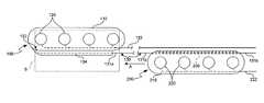
- FIG. 3Aillustrates a stage of percutaneously implanting and assembling a stimulation electrode assembly in vivo at a stimulation site S (shown in dotted lines) within a patient.
- the first electrode unit 100has been percutaneously implanted through a needle, cannula, trocar, catheter, or other suitable percutaneous implanters using known guidance systems to be positioned at the stimulation. site S.
- the first electrode unit 100can be implanted into the epidural space of the spine by inserting a needle through the flavum ligament and into the epidural space and then advancing the first electrode unit 100 into the epidural space via the needle.
- the first electrical line 122 and the guideline 130can extend through the patient and the needle such that the proximal section of the first electrical line 122 and the proximal section 131 b of the guideline 130 are accessible externally of the patient.
- the second electrode unit 200can then be advanced over the guideline 130 and into the patient (arrow A) by inserting the proximal section 131 b of the guideline 130 into the lumen 230 of the second electrode unit 200 .
- the second electrode unit 200can be advanced through the needle, or in other embodiments the needle can be removed from the patient and the second electrode unit 200 can be advanced along the guideline 130 through the percutaneous opening and pathway through the patient created by the needle.
- FIG. 3Billustrates a subsequent stage of a method for implanting the first and second electrode units 100 and 200 to assemble a neural stimulation electrode assembly 300 at the stimulation site S within the patient.
- the second electrode unit 200is advanced along the guideline 130 as shown in FIG. 3A until the distal section 131 a is received in the lumen 230 and the aperture 232 of the lumen 230 is proximate to the end 132 of the guideline 130 .
- the second electrode unit 200can split the casing 134 along the edge 235 .
- the second electrode unit 200is accordingly adjacent to the first electrode unit 100 in a side-by-side configuration within the patient when the second electrode unit 200 is at the distal section 131 a of the guideline 130 .
- the second electrode unit 200can in fact contact or otherwise engage the first electrode unit 100 when the second electrode unit 200 is at the distal section 131 a of the guideline 130 .
- the casing 134is a soft material that splits apart as the second electrode unit 200 advances along the distal section 131 a of the guideline 130 .
- the casing 134can accordingly grip the second electrode unit 200 to inhibit the second electrode unit 200 from moving away from the first electrode unit 100 .
- FIG. 4illustrates an alternative embodiment of the first electrode unit 100 , and like reference numbers refer to like components in FIGS. 3A and 4 .
- the embodiment of the first electrode unit 100 illustrated in FIG. 4is different than the embodiment illustrated in FIG. 3A in that the guideline 130 is also the electrical line that provides the current to the first electrodes 120 .
- the guideline 130 of the embodiment shown in FIG. 4can be an electrically conductive material in which the end 132 extends through the support 110 and electrically contacts the first electrodes 120 .
- FIGS. 5A-5Dillustrate various aspects of a first electrode unit 500 a and a second electrode unit 500 b in accordance with another embodiment.
- the first electrode unit 500 aincludes a first support 510 a having a flexible tip 512 and a first channel 514 a .
- the first electrode unit 500 afurther includes a guideline 518 having a distal section attached to the first support 510 a and a proximal section extending proximally from the distal section.
- a flexible wire stylet 540is inserted in the channel 514 a and pushed against the distal tip 512 to drive the first electrode unit 500 a through a needle and into the patient until the first electrode unit 500 a is positioned at the stimulation site.
- the distal end of the stylet 540can be bent to change the direction of the distal tip 512 (as shown by arrow M) for steering the first electrode unit 500 a through the patient.
- the first support 510 ahas a non-circular cross-sectional shape in the region of the first electrodes 520 a (best shown in FIG. 5D ), the distal tip 512 is flexible and has a circular cross-sectional shape, and the first electrode unit 500 a has a transition portion 513 transitioning from the non-circular cross-section of the first support 510 a to the circular cross-section of the distal tip 512 .
- the non-circular cross-section of the first support 510 acan be oval, elliptical or another shape that provides a lower-wider profile than a circle.
- FIG. 5Billustrates an embodiment of the interaction between the first electrode unit 500 a and the second electrode unit 500 b .
- the second electrode unit 500 bcan include a second support 510 b , a second channel 514 b , and a lumen 530 .
- the stylet 540is placed into the second channel 514 b and the proximal end of the guideline 518 is positioned in the lumen 530 .
- An operatorpushes the stylet 540 distally to slide the second electrode unit 500 b over the guideline 518 via the interface between the guideline 518 and the lumen 530 . Referring to FIG.
- the second electrode unit 500 bis advanced distally until the second electrode unit 500 b is adjacent to the first electrode unit 500 a .
- the paddle portions of the first and second electrode units 500 a and 500 bcan be positioned in a side-by-side relationship in which first electrodes 520 a on the first electrode unit 500 a and second electrodes 520 b on the second electrode unit 500 b face in a common direction and are electrically isolated from the back side surfaces of the first and second electrode units 500 a and 500 b , respectively.
- the interface between the guideline 518 and the lumen 530effectively engages or otherwise interlocks the first and second electrode units 500 a - b together.
- FIG. 6is a cross-sectional view of another embodiment of an assembled electrode assembly 600 having a first electrode unit 601 and a second electrode unit 602 .
- the first electrode unit 601includes a first support 610 a having a paddle portion, at least one first electrode 620 a at the first support 610 a , and a first connector 630 a at a side of the first support 610 a .
- the first electrode unit 601can further include a first channel 611 a extending through the first support 610 a to receive a stylet or guidewire.
- the first electrode unit 601can also include a guideline 640 similar to the guideline 130 described above with reference to FIG. 1A .
- the second electrode unit 602can include a second support 610 b , at least one second electrode 620 b carried by the second support 610 b , a second lumen 611 b through the second support 610 b to receive a guidewire or stylet, and a second connector 630 b having a lumen 650 .
- the first and second connectors 630 a - bare oppositely charged magnets that attract each other.
- the guideline 640 of the first electrode unit 601passes through the lumen 650 of the second electrode unit 602 as the second electrode unit 602 advances distally until the first and second connectors 630 a - b are adjacent to each other.
- the first and second connectors 630 a - bthen attract each other to secure the first and second electrode units 601 and 602 in a side-by-side relationship.
- FIG. 7illustrates an implantable electrode assembly 700 in accordance with yet another embodiment having a first electrode unit 701 and a second electrode unit 702 .
- the first electrode unit 701can have a first support 710 a
- the second electrode unit 702can have a second support 710 b .
- the first and second electrode units 701 and 702can accordingly have one or more electrodes first 720 a and second electrodes 720 b , respectively.
- the first electrode unit 701further includes a first lumen 711 a for receiving a stylet or guidewire, and the second electrode unit 702 can similarly have a second lumen 711 b .
- the first and second electrode units 701 and 702can be coupled together with a tongue and groove assembly.
- the first electrode unit 701can have a first connector 730 a with a longitudinal opening and a larger longitudinal internal cavity.
- the first electrode unit 701can also have a guideline 740 that runs longitudinally through the internal cavity of the first connector 730 a .
- the second electrode unit 702can have a second connector 730 b having a neck 731 configured to fit in the opening of the first connector 730 a and a bulbous portion 732 configured to be received in the internal cavity of the first connector 730 a .
- the bulbous portion 732 of the second connector 730 bis larger than the opening of the first connector 730 a to restrict lateral movement between the first and second electrode units 701 and 702 .
- the second connector 730 bfurther includes a lumen 750 that receives the guideline 740 .
- the bulbous portion of the second connector 730 bslides longitudinally within the larger internal cavity of the first connector 730 a as the lumen 750 advances over the guideline 740 .
- FIG. 8illustrates an embodiment of another electrode assembly 800 having a first electrode unit 801 , a second electrode unit 802 , and a third electrode unit 803 .
- the first electrode unit 801has a first support 810 a with a first channel 811 a to receive a guidewire or stylet, at least one first electrode 820 a carried by the first support 810 a , and grooves 830 on each side of the first support 810 a that define separate connectors.
- the first electrode unit 801can further include a first guideline 840 a at one side of the first support 810 a and a second guideline 840 b at the other side of the first support 810 a .
- the second electrode unit 802 and the third electrode unit 803can be mirror images of each other, or in other embodiments they can have different configurations.
- the second electrode unit 802can accordingly include a second support 810 b with a second channel 811 b , at least one second electrode 820 b carried by the second support 810 b , and a second connector 850 .
- the second connector 850has a tongue 851 configured to fit into the groove 830 and a lumen 852 extending through the tongue 851 .
- the third electrode unit 803can include a third support 810 c having a third channel 811 c , at least one third electrode 820 c carried by the third support 810 c , and a third connector 860 .
- the third connector 860also has a tongue 861 and a lumen 862 extending through the tongue 861 .
- the first guideline 840 ais received in the lumen 852 of the second electrode unit 802 and the second guideline 840 b is received in the lumen 862 of the third electrode unit 803 .
- the first and second electrode units 802 and 803are advanced sequentially along the first and second guidelines 840 a and 840 b through the same percutaneous hole used to implant the first electrode unit 801 into the patient.
- the electrode assembly 800accordingly includes three independently operable electrode units that are passed through one small percutaneous hole and assembled in vivo to cover an area having a cross-section that is much larger than the percutaneous entry hole.
- the electrode assembly 800can accordingly provide monopolar, bi-polar, or tri-polar electrical fields to the neural tissue, muscle tissue, or other type of tissue subject to the electrical stimulation.
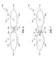
- FIGS. 9A and 9Billustrate different orientations of the embodiment of the electrode assembly 800 illustrated in FIG. 8 .
- the electrode units 801 - 803can be arranged such that the first electrodes 820 a are aligned with either or both of the second electrodes 820 b and the third electrodes 820 c .
- Such a configurationcreates aligned electrical fields E 1 and E 2 .
- the vectors of the electrical fields E 1 and E 2can advantageously provide channel vectors oriented in directions generally followed by the neural structures.
- FIG. 9Athe electrode units 801 - 803 can be arranged such that the first electrodes 820 a are aligned with either or both of the second electrodes 820 b and the third electrodes 820 c .
- Such a configurationcreates aligned electrical fields E 1 and E 2 .
- the vectors of the electrical fields E 1 and E 2can advantageously provide channel vectors oriented in directions generally followed by the neural structures.
- FIG. 9Billustrates an alternative orientation in which the first electrode unit 801 is staggered relative to the second and third electrode units 802 and 803 such that the first and second electrical fields E 1 and E 2 are at an acute angle relative to a medial superior-inferior axis of the spinal cord.
- the particular orientation between the first-third electrode units 801 - 803can be configured to provide channel vectors in directions that generally follow the dorsal routes leaving the dorsal column at the intervertebral foramen of the spinal cord. Proximal to the brain, the dorsal root branches from the spinal column at a generally orthogonal orientation relative to the dorsal column.
- the dorsal rootsbranch from the dorsal column at increasingly inferior angles with respect to the dorsal column such that the degree to which the electrode units 801 - 803 can be staggered relative to each other may be particularly suitable for applications distal of the brain.
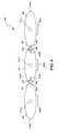
- FIG. 10is a cross-sectional view that illustrates the relationship between the spinal cord, spinal nerves, vertebral column, and an embodiment of a stimulation system 1000 including an implantable pulse generator 1010 and an embodiment of the electrode assembly 800 .
- the anatomyincludes a spinal cord SC, dorsal roots of the spinal nerve DR, ventral roots of the spinal nerve VR, and a dorsal root ganglion DRG.
- the spinal cord SC, dorsal roots DR, and ventral roots VRare surrounded by arachnoid mater A, which is surrounded by dura mater D.
- the neural tissuesare protected by a vertebral body V with transverse processes TP and a spinal process SP.
- the electrode assembly 800is implanted by percutaneously implanting the first electrode unit 801 so that it is generally aligned with a posterior-anterior medial axis.
- the second electrode unit 802is then implanted through the same hole as the first electrode unit 801 on one side of the first electrode unit 801 , and then the third electrode unit 803 is implanted via the same hole on the other side of the first electrode unit 801 .
- the second and third electrode units 802 and 803can be implanted and engaged with the first electrode unit 801 as described above with reference to FIG. 8 .
- the implantable pulse generator 1010is implanted at a suitable location, and electrical lines 860 a - c from the electrode units 801 - 803 are coupled to the pulse generator 1010 .
- the implantable pulse generator 1010can have hardware and/or software containing instructions that cause the pulse generator to provide the desired electrical signals to the patient. Suitable implantable pulse generators, locations for implanting the electrode assembly, and stimulation pulses for dorsal root stimulation are described in U.S. Provisional Patent Application No. 60/985,353 filed on Nov. 5, 2007.
- the electrodes of the first electrode unit 801can be cathodes and the electrodes of the second and third electrode units 802 and 803 can be anodes to create the separate electrical fields E 1 and E 2 that affect the dorsal roots DR.
- the implantable pulse generator 1010can accordingly include instructions that generate such tri-polar electrical fields.
- One aspect of the tri-polar embodiment illustrated in FIG. 10is that the cathodic first electrodes of the first electrode unit 801 depolarize the nerves at the posterior-anterior medial axis where action potentials tend to fire while the anodic second and third electrodes hyperpolarize the nerves along the dorsal roots which decreases the intrinsic threshold and reduces firing of the nerves along the dorsal roots.
- the embodiment of the electrode assembly 800 shown in FIG. 10can be implemented to establish an electrical nerve block without a painful or uncomfortable period before the nerves are blocked.
- Electrodes assemblies described aboveprovide the benefits of a large paddle-type array with the advantages of percutaneous implantation through a single, small percutaneous entry hole.
- the electrode assembliescan use a single percutaneous entry hole and then be assembled to cover a large stimulation area. This is particularly well suited for dorsal root SCS because the large electrode arrays can provide more efficacy for pain relief and the percutaneous implantation reduces discomfort and complications for the patient.
- Several embodiments of the electrode assembliesalso provide beneficial long-term features for SCS. For example, the relatively flat paddle portions of the electrode units do not tend to migrate, and this is particular so when several electrode units are assembled as described above with reference to FIGS. 3A-10 .
- the electrode assembliesconserve power and provide more control over the electrical fields because the electrodes face in a common direction toward the target neural tissue that is desirably subject to stimulation, but the back surfaces of the electrode arrays are electrically insolated from the electrodes such that energy is not wasted on non-target tissue and collateral stimulation is mitigated.
- the term “comprising”is used throughout to mean including at least the recited feature(s) such that any greater number of the same feature and/or additional types of features are not precluded.
- the foregoing embodimentscan also be combined with each other to create more embodiments.
- the casing 134 of the first electrode unit 100 or any of the connectors of the other electrode unitscan be used with the electrode assembly 800 , or any of the first electrode units can have guidewire channels for over-the-wire implantation of the first electrode units. Therefore, the invention is not limited except as by the appended claims.
Landscapes
- Health & Medical Sciences (AREA)
- Neurology (AREA)
- Neurosurgery (AREA)
- Orthopedic Medicine & Surgery (AREA)
- Cardiology (AREA)
- Heart & Thoracic Surgery (AREA)
- Engineering & Computer Science (AREA)
- Biomedical Technology (AREA)
- Nuclear Medicine, Radiotherapy & Molecular Imaging (AREA)
- Radiology & Medical Imaging (AREA)
- Life Sciences & Earth Sciences (AREA)
- Animal Behavior & Ethology (AREA)
- General Health & Medical Sciences (AREA)
- Public Health (AREA)
- Veterinary Medicine (AREA)
- Electrotherapy Devices (AREA)
Abstract
Description
Claims (14)
Priority Applications (3)
| Application Number | Priority Date | Filing Date | Title |
|---|---|---|---|
| US12/468,688US8880176B2 (en) | 2008-05-19 | 2009-05-19 | Implantable neural stimulation electrode assemblies and methods for stimulating spinal neural sites |
| US13/645,387US9403020B2 (en) | 2008-11-04 | 2012-10-04 | Modeling positions of implanted devices in a patient |
| US15/219,126US20170032096A1 (en) | 2008-11-04 | 2016-07-25 | Modeling positions of implanted devices in a patient |
Applications Claiming Priority (2)
| Application Number | Priority Date | Filing Date | Title |
|---|---|---|---|
| US5432708P | 2008-05-19 | 2008-05-19 | |
| US12/468,688US8880176B2 (en) | 2008-05-19 | 2009-05-19 | Implantable neural stimulation electrode assemblies and methods for stimulating spinal neural sites |
Publications (2)
| Publication Number | Publication Date |
|---|---|
| US20090319013A1 US20090319013A1 (en) | 2009-12-24 |
| US8880176B2true US8880176B2 (en) | 2014-11-04 |
Family
ID=40886936
Family Applications (1)
| Application Number | Title | Priority Date | Filing Date |
|---|---|---|---|
| US12/468,688Active2031-12-16US8880176B2 (en) | 2008-05-19 | 2009-05-19 | Implantable neural stimulation electrode assemblies and methods for stimulating spinal neural sites |
Country Status (3)
| Country | Link |
|---|---|
| US (1) | US8880176B2 (en) |
| EP (1) | EP2318090B1 (en) |
| WO (1) | WO2009143177A2 (en) |
Cited By (1)
| Publication number | Priority date | Publication date | Assignee | Title |
|---|---|---|---|---|
| WO2018165391A1 (en)* | 2017-03-09 | 2018-09-13 | Nevro Corp. | Paddle leads and delivery tools, and associated systems and methods |
Families Citing this family (10)
| Publication number | Priority date | Publication date | Assignee | Title |
|---|---|---|---|---|
| US20090204173A1 (en) | 2007-11-05 | 2009-08-13 | Zi-Ping Fang | Multi-Frequency Neural Treatments and Associated Systems and Methods |
| US8428732B2 (en)* | 2008-05-22 | 2013-04-23 | University Of Florida Research Foundation, Inc. | Neural interface systems and methods |
| US8108052B2 (en)* | 2008-05-29 | 2012-01-31 | Nervo Corporation | Percutaneous leads with laterally displaceable portions, and associated systems and methods |
| US9403020B2 (en) | 2008-11-04 | 2016-08-02 | Nevro Corporation | Modeling positions of implanted devices in a patient |
| US8805519B2 (en) | 2010-09-30 | 2014-08-12 | Nevro Corporation | Systems and methods for detecting intrathecal penetration |
| WO2013086420A1 (en)* | 2011-12-07 | 2013-06-13 | Spinal Modulation, Inc. | Neuromodulation of subcellular structures within the dorsal root ganglion |
| US9308022B2 (en) | 2012-12-10 | 2016-04-12 | Nevro Corporation | Lead insertion devices and associated systems and methods |
| US8818483B2 (en) | 2012-12-20 | 2014-08-26 | Boston Scientific Neuromodulation Corporation | Methods of making a paddle lead with a carrier and leads and systems formed thereby |
| JP6137722B2 (en) | 2013-10-30 | 2017-05-31 | ボストン サイエンティフィック ニューロモデュレイション コーポレイション | Split control to avoid dorsal root stimulation |
| WO2019191423A1 (en) | 2018-03-29 | 2019-10-03 | Nevro Corp. | Leads having sidewall openings, and associated systems and methods |
Citations (86)
| Publication number | Priority date | Publication date | Assignee | Title |
|---|---|---|---|---|
| US3738368A (en) | 1970-12-14 | 1973-06-12 | R Avery | Implantable electrodes for the stimulation of the sciatic nerve |
| US4136703A (en) | 1978-03-09 | 1979-01-30 | Vitatron Medical B.V. | Atrial lead and method of inserting same |
| US5042486A (en) | 1989-09-29 | 1991-08-27 | Siemens Aktiengesellschaft | Catheter locatable with non-ionizing field and method for locating same |
| US5078140A (en) | 1986-05-08 | 1992-01-07 | Kwoh Yik S | Imaging device - aided robotic stereotaxis system |
| US5179962A (en) | 1991-06-20 | 1993-01-19 | Possis Medical, Inc. | Cardiac lead with retractible fixators |
| US5211165A (en) | 1991-09-03 | 1993-05-18 | General Electric Company | Tracking system to follow the position and orientation of a device with radiofrequency field gradients |
| US5251634A (en) | 1991-05-03 | 1993-10-12 | Cyberonics, Inc. | Helical nerve electrode |
| US5257636A (en) | 1991-04-02 | 1993-11-02 | Steven J. White | Apparatus for determining position of an endothracheal tube |
| US5325873A (en) | 1992-07-23 | 1994-07-05 | Abbott Laboratories | Tube placement verifier system |
| US5336182A (en) | 1990-02-02 | 1994-08-09 | Ep Technologies, Inc. | Catheter steering mechanism |
| US5354326A (en) | 1993-01-27 | 1994-10-11 | Medtronic, Inc. | Screening cable connector for interface to implanted lead |
| US5375596A (en) | 1992-09-29 | 1994-12-27 | Hdc Corporation | Method and apparatus for determining the position of catheters, tubes, placement guidewires and implantable ports within biological tissue |
| US5392791A (en) | 1992-04-24 | 1995-02-28 | Siemens Elema Ab | Controllable intracardial electrode device |
| US5425367A (en) | 1991-09-04 | 1995-06-20 | Navion Biomedical Corporation | Catheter depth, position and orientation location system |
| US5480421A (en) | 1992-10-30 | 1996-01-02 | Medtronic, Inc. | Lead with stylet capture member |
| US5549555A (en) | 1995-02-22 | 1996-08-27 | Influence, Inc. | Balloon catheter |
| US5641326A (en) | 1993-12-13 | 1997-06-24 | Angeion Corporation | Method and apparatus for independent atrial and ventricular defibrillation |
| US5727553A (en) | 1996-03-25 | 1998-03-17 | Saad; Saad A. | Catheter with integral electromagnetic location identification device |
| US5728148A (en) | 1995-11-08 | 1998-03-17 | Pacesetter Ab | Stylet unit for implanting a medical electrode cable |
| US5733322A (en) | 1995-05-23 | 1998-03-31 | Medtronic, Inc. | Positive fixation percutaneous epidural neurostimulation lead |
| US5741319A (en) | 1995-01-27 | 1998-04-21 | Medtronic, Inc. | Biocompatible medical lead |
| US5824030A (en) | 1995-12-21 | 1998-10-20 | Pacesetter, Inc. | Lead with inter-electrode spacing adjustment |
| US5871531A (en) | 1997-09-25 | 1999-02-16 | Medtronic, Inc. | Medical electrical lead having tapered spiral fixation |
| US5871487A (en) | 1994-06-24 | 1999-02-16 | Cytotherpeutics, Inc. | Microdrive for use in stereotactic surgery |
| US6024702A (en) | 1997-09-03 | 2000-02-15 | Pmt Corporation | Implantable electrode manufactured with flexible printed circuit |
| US6066163A (en) | 1996-02-02 | 2000-05-23 | John; Michael Sasha | Adaptive brain stimulation method and system |
| US6161047A (en) | 1998-04-30 | 2000-12-12 | Medtronic Inc. | Apparatus and method for expanding a stimulation lead body in situ |
| US6192278B1 (en) | 1997-04-25 | 2001-02-20 | Medtronic, Inc. | Medical lead adaptor |
| US6198963B1 (en) | 1996-07-17 | 2001-03-06 | Biosense, Inc. | Position confirmation with learn and test functions |
| US6415187B1 (en) | 1998-02-10 | 2002-07-02 | Advanced Bionics Corporation | Implantable, expandable, multicontact electrodes and insertion needle for use therewith |
| US20020128700A1 (en) | 2001-03-08 | 2002-09-12 | Cross Thomas E. | Lead with adjustable angular and spatial relationships between electrodes |
| US6474341B1 (en) | 1999-10-28 | 2002-11-05 | Surgical Navigation Technologies, Inc. | Surgical communication and power system |
| US20020173718A1 (en) | 2001-05-20 | 2002-11-21 | Mordechai Frisch | Array system and method for locating an in vivo signal source |
| US20030114752A1 (en) | 1999-04-20 | 2003-06-19 | Jaimie Henderson | Instrument guidance method and system for image guided surgery |
| US20030120150A1 (en) | 2001-12-21 | 2003-06-26 | Assaf Govari | Wireless position sensor |
| US20030125786A1 (en) | 2000-07-13 | 2003-07-03 | Gliner Bradford Evan | Methods and apparatus for effectuating a lasting change in a neural-function of a patient |
| US20030136418A1 (en) | 1999-10-29 | 2003-07-24 | Medtronic, Inc. | Tactile feedback for indicating validity of communication link with an implantable medical device |
| US20040097803A1 (en) | 2002-11-20 | 2004-05-20 | Dorin Panescu | 3-D catheter localization using permanent magnets with asymmetrical properties about their longitudinal axis |
| US20040176683A1 (en) | 2003-03-07 | 2004-09-09 | Katherine Whitin | Method and apparatus for tracking insertion depth |
| US20050049486A1 (en) | 2003-08-28 | 2005-03-03 | Urquhart Steven J. | Method and apparatus for performing stereotactic surgery |
| US20050065588A1 (en) | 2003-09-23 | 2005-03-24 | Medtronic, Inc. | Medical electrical lead system including pre-formed J-shape stylet |
| US6875571B2 (en) | 1991-08-22 | 2005-04-05 | The Board Of Trustees Of The Leland Stanford Junior University | NF-AT polypeptides and polynucleotides and screening methods for immunosuppressive agents |
| US20050075684A1 (en) | 2003-10-02 | 2005-04-07 | Phillips William C. | Neurostimulator programmer with clothing attachable antenna |
| US20050085884A1 (en) | 2003-10-20 | 2005-04-21 | O'brien Robert C. | Connection for a coiled lead to an electrical contact for an implantable medical device |
| US6895283B2 (en) | 2000-08-10 | 2005-05-17 | Advanced Neuromodulation Systems, Inc. | Stimulation/sensing lead adapted for percutaneous insertion |
| US20050113882A1 (en) | 2003-11-20 | 2005-05-26 | Advanced Neuromodulation Systems, Inc. | Electrical stimulation system, lead, and method providing reduced neuroplasticity effects |
| US20050154435A1 (en) | 2004-01-14 | 2005-07-14 | Northstar Neuroscience, Inc. | Articulated Neural Electrode Assembly |
| US6934589B2 (en) | 2000-12-29 | 2005-08-23 | Medtronic, Inc. | System and method for placing endocardial leads |
| US20050203599A1 (en)* | 2004-03-12 | 2005-09-15 | Scimed Life Systems, Inc. | Modular stimulation lead network |
| US20050234318A1 (en) | 2001-06-18 | 2005-10-20 | Schulman Joseph H | Miniature implantable connection method |
| US20050251237A1 (en) | 2004-05-10 | 2005-11-10 | Advanced Bionics Corporation | Implantable electrode, insertion tool for use therewith, and insertion method |
| US20060089691A1 (en) | 2004-10-21 | 2006-04-27 | Medtronic, Inc. | Implantable medical lead with axially oriented coiled wire conductors |
| US7072719B2 (en) | 2001-09-20 | 2006-07-04 | Medtronic, Inc. | Implantable percutaneous stimulation lead with interlocking elements |
| US20060161219A1 (en) | 2003-11-20 | 2006-07-20 | Advanced Neuromodulation Systems, Inc. | Electrical stimulation system and method for stimulating multiple locations of target nerve tissue in the brain to treat multiple conditions in the body |
| US20060161235A1 (en) | 2005-01-19 | 2006-07-20 | Medtronic, Inc. | Multiple lead stimulation system and method |
| US7146222B2 (en) | 2002-04-15 | 2006-12-05 | Neurospace, Inc. | Reinforced sensing and stimulation leads and use in detection systems |
| US20070073353A1 (en) | 2005-06-09 | 2007-03-29 | Medtronic, Inc. | Implantable medical device with electrodes on multiple housing surfaces |
| US20070106289A1 (en) | 2005-09-26 | 2007-05-10 | O'sullivan Martin F | System and method for monitoring esophagus proximity |
| US20070239249A1 (en) | 2000-08-01 | 2007-10-11 | Cardiac Pacemakers, Inc. | Lead having varying stiffness and method of manufacturing thereof |
| US20070249901A1 (en) | 2003-03-07 | 2007-10-25 | Ohline Robert M | Instrument having radio frequency identification systems and methods for use |
| US20070255364A1 (en) | 2006-04-27 | 2007-11-01 | Medtronic, Inc. | Implantable medical electrical stimulation lead fixation method and apparatus |
| US20070261115A1 (en) | 2006-04-27 | 2007-11-08 | Medtronic, Inc. | Implantable medical electrical stimulation lead fixation method and apparatus |
| US20070276450A1 (en) | 1999-07-27 | 2007-11-29 | Advanced Bionics Corporation | Rechargeable spinal cord stimulation system |
| US20080039738A1 (en) | 2006-08-11 | 2008-02-14 | Medtronic, Inc. | Guided medical element implantation |
| US20080097475A1 (en) | 2006-09-08 | 2008-04-24 | Viasys Holdings, Inc. | Medical device position guidance system with wireless connectivity between a noninvasive device and an invasive device |
| US7379776B1 (en) | 2005-05-09 | 2008-05-27 | Pacesetter, Inc. | Stylet design |
| US20080125833A1 (en) | 2001-12-04 | 2008-05-29 | Advanced Bionics Corporation | Apparatus and method for determining the relative position and orientation of neurostimulation leads |
| US20080183224A1 (en) | 2007-01-25 | 2008-07-31 | Giancarlo Barolat | Electrode paddle for neurostimulation |
| US7455666B2 (en) | 2001-07-13 | 2008-11-25 | Board Of Regents, The University Of Texas System | Methods and apparatuses for navigating the subarachnoid space |
| US7477945B2 (en) | 2002-02-01 | 2009-01-13 | The Cleveland Clinic Foundation | Delivery device for stimulating the sympathetic nerve chain |
| US20090018630A1 (en) | 2007-07-11 | 2009-01-15 | Osypka Thomas P | Self-expandable epidural cortical electrode |
| US20090204173A1 (en) | 2007-11-05 | 2009-08-13 | Zi-Ping Fang | Multi-Frequency Neural Treatments and Associated Systems and Methods |
| US20090299444A1 (en) | 2008-05-29 | 2009-12-03 | Nevro Corporation | Percutaneous Leads with Laterally Displaceable Portions, and Associated Systems and Methods |
| US20100069736A1 (en) | 1998-10-05 | 2010-03-18 | Spinematrix, Inc. | EMG Electrode Apparatus And Positioning System |
| US7702379B2 (en) | 2004-08-25 | 2010-04-20 | General Electric Company | System and method for hybrid tracking in surgical navigation |
| US7769472B2 (en) | 2005-07-29 | 2010-08-03 | Medtronic, Inc. | Electrical stimulation lead with conformable array of electrodes |
| US20100204569A1 (en) | 2007-11-26 | 2010-08-12 | C. R. Bard, Inc. | System for placement of a catheter including a signal-generating stylet |
| US20110031961A1 (en) | 2008-02-04 | 2011-02-10 | Durand Keith V | Endotracheal tube sensor |
| US7970480B2 (en) | 2006-02-10 | 2011-06-28 | Advanced Neuromodulation Systems, Inc. | Self-folding paddle lead and method of fabricating a paddle lead |
| US20110160568A1 (en) | 2009-12-30 | 2011-06-30 | Medtronic, Inc. | Lead Tracking and Positioning System and Method |
| US7996055B2 (en) | 2006-12-29 | 2011-08-09 | St. Jude Medical, Atrial Fibrillation Division, Inc. | Cardiac navigation system including electrode array for use therewith |
| US8019442B1 (en) | 2006-10-25 | 2011-09-13 | Advanced Neuromodulation Systems, Inc. | Assembly kit for creating paddle-style lead from one or several percutaneous leads and method of lead implantation |
| US8099172B2 (en) | 2006-04-28 | 2012-01-17 | Advanced Neuromodulation Systems, Inc. | Spinal cord stimulation paddle lead and method of making the same |
| US20120083709A1 (en) | 2010-09-30 | 2012-04-05 | Nevro Corporation | Systems and methods for detecting intrathecal penetration |
| US20120083856A1 (en) | 2010-09-30 | 2012-04-05 | Nevro Corporation | Systems and methods for positioning implanted devices in a patient |
| US8326439B2 (en) | 2008-04-16 | 2012-12-04 | Nevro Corporation | Treatment devices with delivery-activated inflatable members, and associated systems and methods for treating the spinal cord and other tissues |
- 2009
- 2009-05-19WOPCT/US2009/044555patent/WO2009143177A2/enactiveApplication Filing
- 2009-05-19EPEP09751405.3Apatent/EP2318090B1/ennot_activeNot-in-force
- 2009-05-19USUS12/468,688patent/US8880176B2/enactiveActive
Patent Citations (91)
| Publication number | Priority date | Publication date | Assignee | Title |
|---|---|---|---|---|
| US3738368A (en) | 1970-12-14 | 1973-06-12 | R Avery | Implantable electrodes for the stimulation of the sciatic nerve |
| US4136703A (en) | 1978-03-09 | 1979-01-30 | Vitatron Medical B.V. | Atrial lead and method of inserting same |
| US5078140A (en) | 1986-05-08 | 1992-01-07 | Kwoh Yik S | Imaging device - aided robotic stereotaxis system |
| US5042486A (en) | 1989-09-29 | 1991-08-27 | Siemens Aktiengesellschaft | Catheter locatable with non-ionizing field and method for locating same |
| US5336182A (en) | 1990-02-02 | 1994-08-09 | Ep Technologies, Inc. | Catheter steering mechanism |
| US5257636A (en) | 1991-04-02 | 1993-11-02 | Steven J. White | Apparatus for determining position of an endothracheal tube |
| US5251634A (en) | 1991-05-03 | 1993-10-12 | Cyberonics, Inc. | Helical nerve electrode |
| US5179962A (en) | 1991-06-20 | 1993-01-19 | Possis Medical, Inc. | Cardiac lead with retractible fixators |
| US6875571B2 (en) | 1991-08-22 | 2005-04-05 | The Board Of Trustees Of The Leland Stanford Junior University | NF-AT polypeptides and polynucleotides and screening methods for immunosuppressive agents |
| US5211165A (en) | 1991-09-03 | 1993-05-18 | General Electric Company | Tracking system to follow the position and orientation of a device with radiofrequency field gradients |
| US5425367A (en) | 1991-09-04 | 1995-06-20 | Navion Biomedical Corporation | Catheter depth, position and orientation location system |
| US5392791A (en) | 1992-04-24 | 1995-02-28 | Siemens Elema Ab | Controllable intracardial electrode device |
| US5325873A (en) | 1992-07-23 | 1994-07-05 | Abbott Laboratories | Tube placement verifier system |
| US5375596A (en) | 1992-09-29 | 1994-12-27 | Hdc Corporation | Method and apparatus for determining the position of catheters, tubes, placement guidewires and implantable ports within biological tissue |
| US5480421A (en) | 1992-10-30 | 1996-01-02 | Medtronic, Inc. | Lead with stylet capture member |
| US5354326A (en) | 1993-01-27 | 1994-10-11 | Medtronic, Inc. | Screening cable connector for interface to implanted lead |
| US5641326A (en) | 1993-12-13 | 1997-06-24 | Angeion Corporation | Method and apparatus for independent atrial and ventricular defibrillation |
| US5871487A (en) | 1994-06-24 | 1999-02-16 | Cytotherpeutics, Inc. | Microdrive for use in stereotactic surgery |
| US5741319A (en) | 1995-01-27 | 1998-04-21 | Medtronic, Inc. | Biocompatible medical lead |
| US5549555A (en) | 1995-02-22 | 1996-08-27 | Influence, Inc. | Balloon catheter |
| US5733322A (en) | 1995-05-23 | 1998-03-31 | Medtronic, Inc. | Positive fixation percutaneous epidural neurostimulation lead |
| US5728148A (en) | 1995-11-08 | 1998-03-17 | Pacesetter Ab | Stylet unit for implanting a medical electrode cable |
| US5824030A (en) | 1995-12-21 | 1998-10-20 | Pacesetter, Inc. | Lead with inter-electrode spacing adjustment |
| US6066163A (en) | 1996-02-02 | 2000-05-23 | John; Michael Sasha | Adaptive brain stimulation method and system |
| US5727553A (en) | 1996-03-25 | 1998-03-17 | Saad; Saad A. | Catheter with integral electromagnetic location identification device |
| US6198963B1 (en) | 1996-07-17 | 2001-03-06 | Biosense, Inc. | Position confirmation with learn and test functions |
| US6192278B1 (en) | 1997-04-25 | 2001-02-20 | Medtronic, Inc. | Medical lead adaptor |
| US6024702A (en) | 1997-09-03 | 2000-02-15 | Pmt Corporation | Implantable electrode manufactured with flexible printed circuit |
| US5871531A (en) | 1997-09-25 | 1999-02-16 | Medtronic, Inc. | Medical electrical lead having tapered spiral fixation |
| US6415187B1 (en) | 1998-02-10 | 2002-07-02 | Advanced Bionics Corporation | Implantable, expandable, multicontact electrodes and insertion needle for use therewith |
| US6714822B2 (en) | 1998-04-30 | 2004-03-30 | Medtronic, Inc. | Apparatus and method for expanding a stimulation lead body in situ |
| US6161047A (en) | 1998-04-30 | 2000-12-12 | Medtronic Inc. | Apparatus and method for expanding a stimulation lead body in situ |
| US20100069736A1 (en) | 1998-10-05 | 2010-03-18 | Spinematrix, Inc. | EMG Electrode Apparatus And Positioning System |
| US20030114752A1 (en) | 1999-04-20 | 2003-06-19 | Jaimie Henderson | Instrument guidance method and system for image guided surgery |
| US20070276450A1 (en) | 1999-07-27 | 2007-11-29 | Advanced Bionics Corporation | Rechargeable spinal cord stimulation system |
| US6474341B1 (en) | 1999-10-28 | 2002-11-05 | Surgical Navigation Technologies, Inc. | Surgical communication and power system |
| US20030136418A1 (en) | 1999-10-29 | 2003-07-24 | Medtronic, Inc. | Tactile feedback for indicating validity of communication link with an implantable medical device |
| US20030125786A1 (en) | 2000-07-13 | 2003-07-03 | Gliner Bradford Evan | Methods and apparatus for effectuating a lasting change in a neural-function of a patient |
| US20070239249A1 (en) | 2000-08-01 | 2007-10-11 | Cardiac Pacemakers, Inc. | Lead having varying stiffness and method of manufacturing thereof |
| US6895283B2 (en) | 2000-08-10 | 2005-05-17 | Advanced Neuromodulation Systems, Inc. | Stimulation/sensing lead adapted for percutaneous insertion |
| US6934589B2 (en) | 2000-12-29 | 2005-08-23 | Medtronic, Inc. | System and method for placing endocardial leads |
| US20020128700A1 (en) | 2001-03-08 | 2002-09-12 | Cross Thomas E. | Lead with adjustable angular and spatial relationships between electrodes |
| US20020173718A1 (en) | 2001-05-20 | 2002-11-21 | Mordechai Frisch | Array system and method for locating an in vivo signal source |
| US20050234318A1 (en) | 2001-06-18 | 2005-10-20 | Schulman Joseph H | Miniature implantable connection method |
| US7455666B2 (en) | 2001-07-13 | 2008-11-25 | Board Of Regents, The University Of Texas System | Methods and apparatuses for navigating the subarachnoid space |
| US7072719B2 (en) | 2001-09-20 | 2006-07-04 | Medtronic, Inc. | Implantable percutaneous stimulation lead with interlocking elements |
| US7363089B2 (en) | 2001-09-20 | 2008-04-22 | Medtronic, Inc. | Method of use of implantable percutaneous stimulation lead |
| US20080125833A1 (en) | 2001-12-04 | 2008-05-29 | Advanced Bionics Corporation | Apparatus and method for determining the relative position and orientation of neurostimulation leads |
| US20030120150A1 (en) | 2001-12-21 | 2003-06-26 | Assaf Govari | Wireless position sensor |
| US7477945B2 (en) | 2002-02-01 | 2009-01-13 | The Cleveland Clinic Foundation | Delivery device for stimulating the sympathetic nerve chain |
| US7146222B2 (en) | 2002-04-15 | 2006-12-05 | Neurospace, Inc. | Reinforced sensing and stimulation leads and use in detection systems |
| US20040097803A1 (en) | 2002-11-20 | 2004-05-20 | Dorin Panescu | 3-D catheter localization using permanent magnets with asymmetrical properties about their longitudinal axis |
| US20070249901A1 (en) | 2003-03-07 | 2007-10-25 | Ohline Robert M | Instrument having radio frequency identification systems and methods for use |
| US20040176683A1 (en) | 2003-03-07 | 2004-09-09 | Katherine Whitin | Method and apparatus for tracking insertion depth |
| US20050049486A1 (en) | 2003-08-28 | 2005-03-03 | Urquhart Steven J. | Method and apparatus for performing stereotactic surgery |
| US20050065588A1 (en) | 2003-09-23 | 2005-03-24 | Medtronic, Inc. | Medical electrical lead system including pre-formed J-shape stylet |
| US20050075684A1 (en) | 2003-10-02 | 2005-04-07 | Phillips William C. | Neurostimulator programmer with clothing attachable antenna |
| US20050085884A1 (en) | 2003-10-20 | 2005-04-21 | O'brien Robert C. | Connection for a coiled lead to an electrical contact for an implantable medical device |
| US20060161219A1 (en) | 2003-11-20 | 2006-07-20 | Advanced Neuromodulation Systems, Inc. | Electrical stimulation system and method for stimulating multiple locations of target nerve tissue in the brain to treat multiple conditions in the body |
| US20050113882A1 (en) | 2003-11-20 | 2005-05-26 | Advanced Neuromodulation Systems, Inc. | Electrical stimulation system, lead, and method providing reduced neuroplasticity effects |
| US20050154435A1 (en) | 2004-01-14 | 2005-07-14 | Northstar Neuroscience, Inc. | Articulated Neural Electrode Assembly |
| US20050203599A1 (en)* | 2004-03-12 | 2005-09-15 | Scimed Life Systems, Inc. | Modular stimulation lead network |
| US7590454B2 (en) | 2004-03-12 | 2009-09-15 | Boston Scientific Neuromodulation Corporation | Modular stimulation lead network |
| US20050251237A1 (en) | 2004-05-10 | 2005-11-10 | Advanced Bionics Corporation | Implantable electrode, insertion tool for use therewith, and insertion method |
| US7702379B2 (en) | 2004-08-25 | 2010-04-20 | General Electric Company | System and method for hybrid tracking in surgical navigation |
| US20060089691A1 (en) | 2004-10-21 | 2006-04-27 | Medtronic, Inc. | Implantable medical lead with axially oriented coiled wire conductors |
| US20060161235A1 (en) | 2005-01-19 | 2006-07-20 | Medtronic, Inc. | Multiple lead stimulation system and method |
| US7379776B1 (en) | 2005-05-09 | 2008-05-27 | Pacesetter, Inc. | Stylet design |
| US20070073353A1 (en) | 2005-06-09 | 2007-03-29 | Medtronic, Inc. | Implantable medical device with electrodes on multiple housing surfaces |
| US7769472B2 (en) | 2005-07-29 | 2010-08-03 | Medtronic, Inc. | Electrical stimulation lead with conformable array of electrodes |
| US20070106289A1 (en) | 2005-09-26 | 2007-05-10 | O'sullivan Martin F | System and method for monitoring esophagus proximity |
| US7970480B2 (en) | 2006-02-10 | 2011-06-28 | Advanced Neuromodulation Systems, Inc. | Self-folding paddle lead and method of fabricating a paddle lead |
| US20070261115A1 (en) | 2006-04-27 | 2007-11-08 | Medtronic, Inc. | Implantable medical electrical stimulation lead fixation method and apparatus |
| US20070255364A1 (en) | 2006-04-27 | 2007-11-01 | Medtronic, Inc. | Implantable medical electrical stimulation lead fixation method and apparatus |
| US8099172B2 (en) | 2006-04-28 | 2012-01-17 | Advanced Neuromodulation Systems, Inc. | Spinal cord stimulation paddle lead and method of making the same |
| US20080039738A1 (en) | 2006-08-11 | 2008-02-14 | Medtronic, Inc. | Guided medical element implantation |
| US8197494B2 (en) | 2006-09-08 | 2012-06-12 | Corpak Medsystems, Inc. | Medical device position guidance system with wireless connectivity between a noninvasive device and an invasive device |
| US20080097475A1 (en) | 2006-09-08 | 2008-04-24 | Viasys Holdings, Inc. | Medical device position guidance system with wireless connectivity between a noninvasive device and an invasive device |
| US8019442B1 (en) | 2006-10-25 | 2011-09-13 | Advanced Neuromodulation Systems, Inc. | Assembly kit for creating paddle-style lead from one or several percutaneous leads and method of lead implantation |
| US7996055B2 (en) | 2006-12-29 | 2011-08-09 | St. Jude Medical, Atrial Fibrillation Division, Inc. | Cardiac navigation system including electrode array for use therewith |
| US20080183224A1 (en) | 2007-01-25 | 2008-07-31 | Giancarlo Barolat | Electrode paddle for neurostimulation |
| US20090018630A1 (en) | 2007-07-11 | 2009-01-15 | Osypka Thomas P | Self-expandable epidural cortical electrode |
| US20090204173A1 (en) | 2007-11-05 | 2009-08-13 | Zi-Ping Fang | Multi-Frequency Neural Treatments and Associated Systems and Methods |
| US20100204569A1 (en) | 2007-11-26 | 2010-08-12 | C. R. Bard, Inc. | System for placement of a catheter including a signal-generating stylet |
| US20110031961A1 (en) | 2008-02-04 | 2011-02-10 | Durand Keith V | Endotracheal tube sensor |
| US8326439B2 (en) | 2008-04-16 | 2012-12-04 | Nevro Corporation | Treatment devices with delivery-activated inflatable members, and associated systems and methods for treating the spinal cord and other tissues |
| US20130144305A1 (en) | 2008-04-16 | 2013-06-06 | Nevro Corporation | Treatment devices with deliver-activated inflatable members, and associated systems and methods for treating the spinal cord and other tissues |
| US20090299444A1 (en) | 2008-05-29 | 2009-12-03 | Nevro Corporation | Percutaneous Leads with Laterally Displaceable Portions, and Associated Systems and Methods |
| US20110160568A1 (en) | 2009-12-30 | 2011-06-30 | Medtronic, Inc. | Lead Tracking and Positioning System and Method |
| US20120083709A1 (en) | 2010-09-30 | 2012-04-05 | Nevro Corporation | Systems and methods for detecting intrathecal penetration |
| US20120083856A1 (en) | 2010-09-30 | 2012-04-05 | Nevro Corporation | Systems and methods for positioning implanted devices in a patient |
Non-Patent Citations (2)
| Title |
|---|
| International Search Report and Written Opinion; International Application No. PCT/US2009/044555, Applicant: Nevro Corporation; European Patent Office; mailed Dec. 2, 2009, 18 pages. |
| Partial International Search Report, International Application No. PCT/US2009/044555, Applicant: Nevro Corporation, mailed Aug. 13, 2009, 6 pages, European Patent Office. |
Cited By (3)
| Publication number | Priority date | Publication date | Assignee | Title |
|---|---|---|---|---|
| WO2018165391A1 (en)* | 2017-03-09 | 2018-09-13 | Nevro Corp. | Paddle leads and delivery tools, and associated systems and methods |
| US10980999B2 (en) | 2017-03-09 | 2021-04-20 | Nevro Corp. | Paddle leads and delivery tools, and associated systems and methods |
| US11759631B2 (en) | 2017-03-09 | 2023-09-19 | Nevro Corp. | Paddle leads and delivery tools, and associated systems and methods |
Also Published As
| Publication number | Publication date |
|---|---|
| WO2009143177A2 (en) | 2009-11-26 |
| WO2009143177A3 (en) | 2010-01-21 |
| EP2318090A2 (en) | 2011-05-11 |
| US20090319013A1 (en) | 2009-12-24 |
| EP2318090B1 (en) | 2016-01-13 |
Similar Documents
| Publication | Publication Date | Title |
|---|---|---|
| US8880176B2 (en) | Implantable neural stimulation electrode assemblies and methods for stimulating spinal neural sites | |
| US7590454B2 (en) | Modular stimulation lead network | |
| US8805543B2 (en) | Insertion tool for paddle-style electrode | |
| EP2854669B1 (en) | Percutaneous implantation kit for an electrical stimulation lead for stimulating dorsal root ganglion | |
| US6909918B2 (en) | Implantable percutaneous stimulation lead with lead carrier | |
| US8805544B2 (en) | Insertion tool for paddle-style electrode | |
| US7072719B2 (en) | Implantable percutaneous stimulation lead with interlocking elements | |
| US8983625B2 (en) | Systems and methods for electrically stimulating patient tissue on or around one or more bony structures | |
| EP2429407B1 (en) | Systems and devices for neuromodulating spinal anatomy | |
| US20060161235A1 (en) | Multiple lead stimulation system and method | |
| US9327111B2 (en) | Systems and methods for making and using electrode configurations for paddle leads | |
| US20070213795A1 (en) | Implantable medical lead | |
| US20060161236A1 (en) | Apparatus for multiple site stimulation | |
| US9144673B2 (en) | Self anchoring lead | |
| US11420045B2 (en) | Leads having sidewall openings, and associated systems and methods | |
| US20180021569A1 (en) | Systems and methods for making and using an electrical stimulation system for stimulation of dorsal root ganglia | |
| US10376689B2 (en) | Leads for extraforaminal stimulation of dorsal roots and dorsal root ganglia and related methods | |
| US20250025687A1 (en) | Medical lead and method of securing medical electrode leads | |
| US10342578B2 (en) | Paddle lead delivery tools |
Legal Events
| Date | Code | Title | Description |
|---|---|---|---|
| AS | Assignment | Owner name:NEVRO CORPORATION, CALIFORNIA Free format text:ASSIGNMENT OF ASSIGNORS INTEREST;ASSIGNORS:BOLING, C. LANCE;CAPARSO, ANTHONY V.;REEL/FRAME:023186/0261 Effective date:20090811 | |
| STCF | Information on status: patent grant | Free format text:PATENTED CASE | |
| AS | Assignment | Owner name:CAPITAL ROYALTY PARTNERS II - PARALLEL FUND "A" L. Free format text:SECURITY INTEREST;ASSIGNOR:NEVRO CORP.;REEL/FRAME:034619/0546 Effective date:20141212 Owner name:CAPITAL ROYALTY PARTNERS II L.P., TEXAS Free format text:SECURITY INTEREST;ASSIGNOR:NEVRO CORP.;REEL/FRAME:034619/0546 Effective date:20141212 Owner name:PARALLEL INVESTMENT OPPORTUNITIES PARTNERS II L.P. Free format text:SECURITY INTEREST;ASSIGNOR:NEVRO CORP.;REEL/FRAME:034619/0546 Effective date:20141212 | |
| FEPP | Fee payment procedure | Free format text:PAT HOLDER NO LONGER CLAIMS SMALL ENTITY STATUS, ENTITY STATUS SET TO UNDISCOUNTED (ORIGINAL EVENT CODE: STOL); ENTITY STATUS OF PATENT OWNER: LARGE ENTITY | |
| AS | Assignment | Owner name:CRG SERVICING LLC,, TEXAS Free format text:ASSIGNMENT AGREEMENT (REAFFIRMATION);ASSIGNORS:CAPITAL ROYALTY PARTNERS II L.P.;CAPITAL ROYALTY PARTNERS II - PARALLEL FUND;PARALLEL INVESTMENT OPPORTUNITIES PARTNERS II L.P.;REEL/FRAME:038984/0865 Effective date:20160613 Owner name:CRG SERVICING LLC,, TEXAS Free format text:ASSIGNMENT AGREEMENT (REAFFIRMATION);ASSIGNORS:CAPITAL ROYALTY PARTNERS II L.P.;CAPITAL ROYALTY PARTNERS II - PARALLEL FUND "A" L.P.;PARALLEL INVESTMENT OPPORTUNITIES PARTNERS II L.P.;REEL/FRAME:038984/0865 Effective date:20160613 | |
| AS | Assignment | Owner name:NEVRO CORP., CALIFORNIA Free format text:RELEASE BY SECURED PARTY;ASSIGNOR:CRG SERVICING LLC;REEL/FRAME:039168/0890 Effective date:20160613 | |
| MAFP | Maintenance fee payment | Free format text:PAYMENT OF MAINTENANCE FEE, 4TH YEAR, LARGE ENTITY (ORIGINAL EVENT CODE: M1551) Year of fee payment:4 | |
| MAFP | Maintenance fee payment | Free format text:PAYMENT OF MAINTENANCE FEE, 8TH YEAR, LARGE ENTITY (ORIGINAL EVENT CODE: M1552); ENTITY STATUS OF PATENT OWNER: LARGE ENTITY Year of fee payment:8 | |
| AS | Assignment | Owner name:WILMINGTON TRUST, NATIONAL ASSOCIATION, AS AGENT, MINNESOTA Free format text:PATENT SECURITY AGREEMENT;ASSIGNOR:NEVRO CORP.;REEL/FRAME:065744/0302 Effective date:20231130 | |
| AS | Assignment | Owner name:NEVRO CORP., CALIFORNIA Free format text:RELEASE BY SECURED PARTY;ASSIGNOR:WILMINGTON TRUST, NATIONAL ASSOCIATION, AS AGENT;REEL/FRAME:070743/0001 Effective date:20250403 |