US8879882B2 - Variably configurable and modular local convergence point - Google Patents
Variably configurable and modular local convergence pointDownload PDFInfo
- Publication number
- US8879882B2 US8879882B2US13/094,572US201113094572AUS8879882B2US 8879882 B2US8879882 B2US 8879882B2US 201113094572 AUS201113094572 AUS 201113094572AUS 8879882 B2US8879882 B2US 8879882B2
- Authority
- US
- United States
- Prior art keywords
- fiber optic
- cassette
- optic terminal
- movable chassis
- cover
- Prior art date
- Legal status (The legal status is an assumption and is not a legal conclusion. Google has not performed a legal analysis and makes no representation as to the accuracy of the status listed.)
- Active, expires
Links
Images


Classifications
- G—PHYSICS
- G02—OPTICS
- G02B—OPTICAL ELEMENTS, SYSTEMS OR APPARATUS
- G02B6/00—Light guides; Structural details of arrangements comprising light guides and other optical elements, e.g. couplings
- G02B6/44—Mechanical structures for providing tensile strength and external protection for fibres, e.g. optical transmission cables
- G02B6/4439—Auxiliary devices
- G02B6/4471—Terminating devices ; Cable clamps
- G—PHYSICS
- G02—OPTICS
- G02B—OPTICAL ELEMENTS, SYSTEMS OR APPARATUS
- G02B6/00—Light guides; Structural details of arrangements comprising light guides and other optical elements, e.g. couplings
- G02B6/44—Mechanical structures for providing tensile strength and external protection for fibres, e.g. optical transmission cables
- G02B6/4439—Auxiliary devices
- G02B6/444—Systems or boxes with surplus lengths
- G02B6/4452—Distribution frames
- G02B6/44524—Distribution frames with frame parts or auxiliary devices mounted on the frame and collectively not covering a whole width of the frame or rack
- G—PHYSICS
- G02—OPTICS
- G02B—OPTICAL ELEMENTS, SYSTEMS OR APPARATUS
- G02B6/00—Light guides; Structural details of arrangements comprising light guides and other optical elements, e.g. couplings
- G02B6/44—Mechanical structures for providing tensile strength and external protection for fibres, e.g. optical transmission cables
- G02B6/4439—Auxiliary devices
- G02B6/444—Systems or boxes with surplus lengths
- G02B6/44528—Patch-cords; Connector arrangements in the system or in the box
- G—PHYSICS
- G02—OPTICS
- G02B—OPTICAL ELEMENTS, SYSTEMS OR APPARATUS
- G02B6/00—Light guides; Structural details of arrangements comprising light guides and other optical elements, e.g. couplings
- G02B6/44—Mechanical structures for providing tensile strength and external protection for fibres, e.g. optical transmission cables
- G02B6/4439—Auxiliary devices
- G02B6/444—Systems or boxes with surplus lengths
- G02B6/4452—Distribution frames
- G—PHYSICS
- G02—OPTICS
- G02B—OPTICAL ELEMENTS, SYSTEMS OR APPARATUS
- G02B6/00—Light guides; Structural details of arrangements comprising light guides and other optical elements, e.g. couplings
- G02B6/44—Mechanical structures for providing tensile strength and external protection for fibres, e.g. optical transmission cables
- G02B6/4439—Auxiliary devices
- G02B6/444—Systems or boxes with surplus lengths
- G02B6/4453—Cassettes
- G02B6/4454—Cassettes with splices
- Y—GENERAL TAGGING OF NEW TECHNOLOGICAL DEVELOPMENTS; GENERAL TAGGING OF CROSS-SECTIONAL TECHNOLOGIES SPANNING OVER SEVERAL SECTIONS OF THE IPC; TECHNICAL SUBJECTS COVERED BY FORMER USPC CROSS-REFERENCE ART COLLECTIONS [XRACs] AND DIGESTS
- Y10—TECHNICAL SUBJECTS COVERED BY FORMER USPC
- Y10T—TECHNICAL SUBJECTS COVERED BY FORMER US CLASSIFICATION
- Y10T29/00—Metal working
- Y10T29/49—Method of mechanical manufacture
- Y10T29/49826—Assembling or joining
Definitions
- the present inventionrelates generally to fiber optic terminals, and more particularly to a fiber optic terminal which provide a local convergence point between a service provider and a subscriber in a fiber optic network that has a small form factor and is variably configurable and modular.
- Fiber optic terminals in a fiber optic networkmay be referred to as local convergence points (LCP), fiber distribution terminals (FDT), fiber distribution hubs (FDH), and the like.
- Such fiber optic terminalsare typically cabinets or enclosures which may house fiber connection points, splices and splitters.
- the splitterssplit an optical signal from a network operator or service provider into many optical signals for distribution to subscribers. This enables the transmission of optical signals over optical fibers connected to the terminals and extended towards the subscriber premises in the optical networks.
- the fiber optic terminalprovides a convergence point for the fibers and the optical signals between the network operator or service provider and the subscriber.
- the convergence pointoffers management capabilities to the network operator or service provider.
- current fiber optic terminalslack features and design which would be beneficial in deploying an all-fiber access network, especially for broadband service providers, such as cable TV companies, and others, including, but not limited to, telcos, CLECs and municipalities.
- Embodiments disclosed hereininclude a fiber optic terminal as a local convergence point in a fiber optic network.
- the fiber optic terminalhas an enclosure having a base and a cover which define an interior space.
- a feeder cable having at least one optical fiber and a distribution cable having at least one optical fiberare received into the interior space through a feeder cable port and a distribution cable port, respectively.
- a movable chassispositions in the interior space and is movable between a first position, a second position and third position.
- the movable chassishas a splitter holder area, a cassette area and a parking area. At least one cassette movably positions in the cassette area.
- a splitter module holderhaving a splitter module movably positioned therein movably positions in the splitter holder area.
- the optical fiber of the feeder cable and the optical fiber of the distribution cableare optically connected through the cassette.
- the optical connection between the optical fiber of the feeder cable and the optical fiber of the distribution cablemay be made through the splitter module.
- the optical fiber of the feeder cableoptically connects to an input optical fiber of the splitter module, where the optical signal is split into a plurality of output optical signals carried by output optical fibers in the form of splitter legs.
- One of the plurality of output optical fibers or splitter legsconnects to the optical fiber of the distribution cable for distribution towards a subscriber premises.
- one of the output fibers or splitter legsmay connect to a connector holder in the parking area.
- the interior spaceis variably configurable by changeably positioning at the least one cassettes and the splitter modules in the movable chassis.
- the at least one cassettemay be a feeder cassette and/or a distribution cassette.
- the movable chassispositions in the first position. In the first position, the movable chassis positions in the base adjacent to a back of the base. When the enclosure is opened, the movable chassis automatically moves from the first position to the second position In the second position, the movable chassis is partially extended from the base and tilted away from the cover. The second position facilitates access to the cassettes and the splitter modules. Also when the enclosure is open, the movable chassis may position in the third position. In the third position, the movable chassis positions in the cover. When the movable chassis is in the third position, access to a fiber management area in the base is provided.
- a protective shieldmovably attaches to the movable chassis.
- the protective shieldrotates or pivots between a covered position and a raised position. In the covered position, the protective shield covers at least a portion of the movable chassis including the splitter module holder, the feeder cassettes, the distribution cassettes, and the parking area.
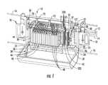
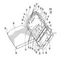
- FIG. 1is a front, perspective view of an exemplary embodiment of a fiber optic terminal installed in an aerial environment from a strand with the cover opened showing splice holder modules, feeder cassettes, distribution cassettes, connector holder block mounted in a movable chassis; and other components located therein;
- FIG. 2is a front, perspective view of the fiber optic terminal of FIG. 1 , with the optical components removed to illustrate guide rails used to mount the splice holder modules, feeder cassettes, distribution cassettes in the movable chassis, and a parking area for mounting the connector holder block in the movable chassis;
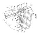
- FIG. 3is a left side elevation of the fiber optic terminal of FIG. 1 illustrating a connection assembly between the cover, the movable chassis and a base of the fiber optic terminal and the movable chassis in an extended position;
- FIG. 4is a partial detail of a right side elevation of the fiber optic terminal of FIG. 1 illustrating the connection assembly between the movable chassis and the base;
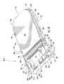
- FIG. 5is a front, perspective view of the open fiber optic terminal of FIG. 1 , with a protective shield covering the splice holder modules, feeder cassettes, distribution cassettes, connector holder block mounted in a movable chassis;
- FIG. 6is a right side elevation of the fiber optic terminal of FIG. 1 with the cover closed illustrating the arrangement of the movable chassis in a base position;
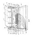
- FIG. 7is a front, perspective view of the fiber optic terminal of FIG. 1 illustrating the movable chassis in a cover position and components mounted in the base;
- FIG. 8is a top, perspective view of a splitter module holder without splitter modules mounted therein;
- FIG. 9is a top, perspective view of the splitter module holder of FIG. 7 including splitter modules mounted therein;
- FIG. 10is a top, perspective view of a cassette with a front section and a rear section and cassette cover closed over the rear section, and a frame assembly in a first position at the front section;
- FIG. 11is a top, perspective view of the cassette of FIG. 10 with the frame assembly rotated to a second position;
- FIG. 12is a top, perspective view of the cassette of FIG. 10 with the cassette cover open showing a mounting area at a first mounting side of a mounting base in the rear section;
- FIG. 13is a top, perspective view of the cassette of FIG. 10 with the cassette cover open showing a splice holder mounted in the mounting area at a first mounting side;
- FIG. 14is a top, perspective view of the cassette of FIG. 10 with the cassette cover open showing a CWDM module mounted in the mounting area at a first mounting side;
- FIG. 15is a top, perspective view of the cassette of FIG. 10 with the cassette cover open showing a multi-fiber adapter and connector mounted in the mounting area at a first mounting side;
- FIG. 16is a bottom, plan view of the cassette of FIG. 10 showing a buffer tube slack storage mounted on the second side of the mounting base in the rear section;
- FIG. 17is a bottom, perspective view of the cassette of FIG. 10 showing the buffer tube slack storage of FIG. 13 ;
- FIG. 18Ais a front, perspective view of the rail guide mounted in the movable chassis
- FIG. 18Bis a rear, perspective view of the rail guide of FIG. 18A ;
- FIG. 19is a block diagram illustrating an exemplary embodiment of optical fiber routing and connections between a enclosure splice tray, a feeder cassette, a distribution cassette, a splitter module, and connection holders in the fiber optic terminal;
- FIG. 20is a block diagram illustrating an exemplary embodiment of optical fiber routing and connections in the fiber optic terminal configured as a cross-connect;
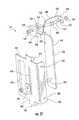
- FIG. 21is an exploded, perspective view of an exemplary embodiment of a strand attachment assembly for suspending the fiber optic terminal from a strand in the aerial environment;
- FIG. 22is a partial, detail, perspective view of the base illustrating ports and strain relief devices and a grounding assembly in the fiber optic terminal;
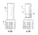
- FIGS. 23A and 23Bare front, elevation views of the fiber optic terminal of FIG. 1 mounted on a pedestal with a pedestal cover installed and with the pedestal cover removed and illustrating a pedestal mounting bracket;
- FIG. 24Ais a front, elevation view of the fiber optic terminal of FIG. 1 mounted on a “dog-house” style support using an inclinable frame;
- FIG. 24Bis a top, perspective view of the fiber optic terminal mounted on the “dog-house” style support in FIG. 24A with the inclinable frame adjusted to incline the fiber optic terminal at an angle to facilitate access to the fiber optic terminal;
- FIG. 25is a front, elevation view of the fiber optic terminal of FIG. 1 mounted on a “dog-house” style support using the hanger attachment assembly to suspend the fiber optic terminal from a suspended bar frame;
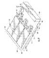
- FIG. 26is a top, perspective view of the fiber optic terminal of FIG. 1 mounted on a rack;
- FIG. 27is a top, perspective view of the fiber optic terminal of FIG. 1 mounted on a wall;
- FIG. 28is a top, perspective view of the fiber optic terminal of FIG. 1 mounted on a pole;
- Embodiments disclosed in the detailed descriptioninclude a fiber optic terminal, which may also be referred to as a local convergence point (LCP), a fiber distribution hub (FDH), a fiber distribution terminal (FDT), or the like, that is a highly versatile package with easy access to optical fiber and optical components routed to and/or positioned in the fiber optic terminal for subscriber configuration.
- the optical componentsmay include but not be limited to, splice trays, splice holders, optical signal power and wavelength managing components, including, without limitation, splitter modules, wave division multiplexers/demultiplexers (WDM), and the like, fiber optic connection modules, connector holder blocks, connector holders, fiber optic adapters and connectors, routing guides, and/or routing clips.
- WDMwave division multiplexers/demultiplexers
- splitter moduleshould be under stood to include any form of optical power splitting, coupling, or wavelength managing device, including without limitation, a passive optical splitter, fused biconic taper coupler (FBT) wave length division multiplexer/demultiplexer (WDM), coarse wavelength division multiplexer/demultiplexer (CWDM), dense wave division multiplexer/demultiplexer (DWDM), and the like.
- FBTfused biconic taper coupler
- WDMwave length division multiplexer/demultiplexer
- CWDMcoarse wavelength division multiplexer/demultiplexer
- DWDMdense wave division multiplexer/demultiplexer
- the fiber optic terminalmay comprise a shell or other enclosure that defines an interior space and at least one cable entry port.
- the fiber optic terminalmay be configured to receive through the at least one entry port at least one optical feeder cable comprising one or more optical fibers.
- feeder cableas used herein should be understood to include, without limitation, a transport cable, a back haul cable, and the like.
- the fiber optic terminalmay be configured to receive through another one of the at least one entry port at least one optical distribution cable comprising one or more optical fibers.
- the term “distribution cable” as used hereinshould be understood to include, without limitation, a branch cable, a drop cable, and the like.
- connection moduleand “cassette” may be used interchangeably, and as used herein should be understood to include any module, cassette, panel, or the like, used for interconnecting optical fibers.
- an optical signal carried by the optical fiber in the feeder cable from a service provider' central office, switching station, head end, or the likemay also be carried by an optical fiber in the distribution cable and extended to a subscriber's premises.
- the fiber optic terminalmay be configured to establish an optical connection between one or more feeder cables and/or between one or more distribution cables through at least one fiber optic connection module. In this manner, optical connectivity may be established between the service provider and the subscriber in an FTTX fiber optic network employing different network architectures.
- the splitter modules and connection modules positioned inside the enclosuremay be variably configurable as desired.
- the fiber optic terminalmay be configured to have a size and cost compatible with any size, design, or architecture of the fiber optic network.
- the fiber optic terminalmay be configured for a centralized splitting architecture in which a splitter module splits the optical signal on one of the optical fibers of the feeder cable into multiple optical signals for distribution on optical fibers of a distribution cable to subscriber premises.
- the fiber optic terminalmay be configured for a distributed split architecture in which a splitter module splits the optical signal on one of the optical fibers of the feeder cable into multiple optical signals which are then transmitted to one or more other fiber optic terminals for additional splitting before distribution to subscriber premises.
- the fiber optic terminalmay be initially configured for smaller subscriber premises groups, such as small housing developments and phases of developments, so that the subscriber premises in the development may be connected cost effectively.
- the fiber optic terminalmay subsequently be re-configured for larger developments, and may be connected by including additional components in the housing.
- the fiber optic terminalmay be configured as one of multiple fiber optic terminals interconnected in a ring topology used to enable transmission of different wavelengths of the optical signal over a multiplexed distribution portion of the fiber optic network.
- a CWDM or DWDMmay be used as an add/drop multiplexer to drop and add wavelengths at one or more of the fiber optic terminals in the ring topology.
- the fiber optic terminalmay be configured without splitter module function, and used as a cross-connect and/or interconnect device.
- any type of optical or electronic, active or passive componentmay be positioned in the interior space of the fiber optic terminal. In this manner, the fiber optic terminal may be configured exactly to the application, avoiding the cost of unneeded components and functionality.
- the fiber optic terminalis designed to be versatile such that it can be universally mounted in different environments without modification or re-design.
- the fiber optic terminalmay be mounted on a strand, a wall, a pole, a pedestal, a rack or in a “dog-house” to provide compatibility with service providers, including cable service providers, current mounting preferences.
- the fiber optic terminalmay be sealed to allow for below-ground installation.
- Other benefits of the fiber optic terminalbeing variably configurable and modular are that only a limited number of parts have to be stocked and the needed configuration may be performed in the field.
- internal splice capabilityespecially in a sealed package, may be provided without the need for additional enclosures.
- the fiber optic terminalmay obviate the need for an external enclosure to splice cable stubs, reducing costs.
- the fiber optic terminalmay be worked on at ground level and then placed on an aerial strand, or lifted from a pedestal/hand hole and worked on nearby. When the work is completed the fiber optic terminal may be placed on the strand or pedestal/hand hole. In this way, the fiber optic terminal may be worked on in the horizontal and vertical position. Thus, there may be no need to take the fiber optic terminal down or move it, except to lift it from a hand hole, to make routing connections, perform testing, etc.
- the fiber optic terminalmay be used outside or indoors, for example, in a multiple dwelling unit (MDU) application.
- Feeder cable and distribution cable optical fibersmay reside in the same cables in links to and between fiber optic terminals, saving on installation costs. These may be managed separately in the interior space of the fiber optic terminal by keeping feeder and distribution fibers in separate buffer tubes or ribbons.
- the fiber optic terminalmay provide for grounding and bonding of armored cables and those with metallic elements. The grounding may be simple common grounding or one that provides for toning of the metallic elements being grounded.
- the fiber optic terminalprovides capacity and versatility in a small form factor and in the manner in which it can be mounted accessed and connected.
- the fiber optic terminalmay be manufactured from any type of material, including, but not limited to, plastic and/or metal. Additionally, the fiber optic terminal may comprise an enclosure having at least two sections that define and/or allow the enclosure to define an interior space.
- the sectionsmay be a base and a cover hingedly connected so that the enclosure may be opened or closed by rotating one or more of the base and the cover to allow access to the interior space. When closed the base and the cover may meet. The enclosure may then be sealed against the environment by appropriate latching mechanisms and/or sealing material.
- an extension or lipmay be formed on the enclosure. The extension and/or lip may be hingedly attached to the section and extend at least a portion of the length of the enclosure. When enclosure is closed, the extension or lip may extend over the interface between the base and cover for rain and/or water tight protection of the enclosure.
- the fiber optic terminalmay have other features and attributes, including but not limited to, a separate enclosure splice tray, which may allow for concatenating multiple fiber optic terminals together by splicing another feeder cable section to excess fibers of the feeder cable. In this way, multiple fiber optic terminals may be concatenated or series connected to cover a wider serving area with the smaller aesthetic foot print or form factor.
- the fiber optic terminalmay be configured to accept stubbed and non-stubbed, internally spliced and preconnectorized cables and is able to accommodate different cable entries in the same fiber optic terminal.
- the feeder cable and the distribution cablemay enter the fiber optic terminal from one side in a butt configuration or from both sides.
- the entry ports of the fiber optic terminalmay have hubs and/or grommets allowing the feeder cables and/or the distribution cables to enter directly into the fiber optic terminal.
- the entry portsmay have fiber optic adapters seated therein to provide for the fiber optic cables to optically connect at the enclosure with optical fibers routed within the fiber optic terminals.
- the feeder cables and/or distribution cablesmay enter the enclosure of the fiber optic terminal as raw cables or interconnect with the fiber optic terminal as connectorized/preconnectorized cable.
- the fiber optic terminalmay accept field-installed connectors or pre-connectorized connectors, such as the MTP, OptiTapTM and OptiTipTM fiber optic connectors as from Coming Cable Systems LLC of Hickory, N.C. to name just a few.
- fiber optic cablesand/or “optical fibers” include all types of single mode and multi-mode light waveguides, including one or more optical fibers that may be upcoated, colored, buffered, ribbonized and/or have other organizing or protective structure in a cable such as one or more tubes, strength members, jackets or the like.
- other types of suitable optical fibersinclude bend-insensitive optical fibers, or any other expedient of a medium for transmitting light signals.
- An example of a bend-insensitive optical fiberis ClearCurve® Multimode fiber commercially available from Corning Incorporated.
- a movable chassis adapted to hold one or more splitter modules, cassettes and/or a parking areamay be positioned within the fiber optic terminal.
- the movable chassisprovides an internal interior space that nests within the interior space of the enclosure.
- the splitter modulemay be movably positioned in splitter module holder, which may then be movably positioned in the movable chassis.
- Splitter legs output from the splitter modulemay be parked in a connector holder in the parking area until needed to connect a subscriber. When a subscriber is connected, an available splitter leg may be routed from the parking area storing any slack on routing guides.
- the splitter legmay be connected to a designated fiber optic adapter in one of the cassettes.
- the fiber optic adapter in the cassettemay be configured to provide optical connection between connectors inserted in the adapter.
- Splitter legsmay be kept short to facilitate management and avoid entanglement.
- the fiber optic terminalmay be configured for any number of subscriber premises. This may be accomplished by the number and type of the splitter modules and the cassettes.
- the splitter modulesmay provide for equal splits or for unequal splits, and/or may be optical power or wavelength division multiplexer/demultiplexer type. For example, if the fiber optic terminal is to address 128 subscriber premises, then, four 1 ⁇ 32 splitter modules may be used. If the number of subscriber premises increases, then additional splitter modules may be added. Additionally, any other quantity or optical signal split multiple splitter modules may be used, including without limitation, 1 ⁇ 4, 1 ⁇ 8, and 1 ⁇ 16, or any other 1 ⁇ N optical signal split multiple.
- the cassettemay be a feeder cassette or a distribution cassette.
- the feeder cassette and distribution cassettemay use a single platform or frame to allow for interchangeability.
- the feeder cassette and distribution cassettemay be variably configurable by inserting one or more components for the intended function, such as for splicing or multi-fiber connection, as examples.
- the feeder cassettes and distribution cassettesmay function as both a connector panel and as a splice tray.
- the movable chassismay be configured to allow for pass-though optical fibers and other inefficiencies in areas that may not have uniformly grouped subscriber premises.
- FIG. 1illustrates a fiber optic terminal 10 according to one embodiment of the disclosure.
- the fiber optic terminal 10provides a convenient access and local convergence point in a telecommunications or data network for a field technician to install, configure and reconfigure optical fiber connections between feeder cables and distribution cables.
- the fiber optic terminal 10is configured to allow one or more optical fibers provided in one or more feeder cables 12 to be easily and readily interconnected with one or more optical fibers in one or more distribution cables 14 .
- the feeder cables 12may also be referred to as “upstream” or “network-side” cables.
- the distribution cables 14may also be referred to as “downstream” or “subscriber-side” cables.
- upstreamor “network-side” it is meant that the optical fiber, fiber optic cable, or optical connection, as the case may be, are provided between a central switching point, central office, head end or the like and the fiber optic terminal 10 .
- downstreamor “subscriber-side,” it is meant that optical fiber, fiber optic cable, or optical connection, as the case may be, are provided between the end subscriber and the fiber optic terminal 10 .
- the fiber optic terminal 10is depicted in an aerial installation, but the fiber optic terminal 10 may be installed in other installation environments, as will be further discussed herein.
- the fiber optic terminalis suspended from a strand 16 .
- the strandmay be one strung between two supports, such as, for example, utility poles (not shown), to provide an elevated, out-of-the-way and secured installation for the fiber optic terminal 10 , but one still easily accessible by a field technician or other authorized personnel.
- the fiber optic terminal 10may be suspended from the strand 16 by an attachment assembly in the form of a hanger bracket assembly 18 .
- Two hanger bracket assemblies 18may be included with one each of the hanger bracket assemblies 18 located at either side of the fiber optic terminal 10 .
- the hanger bracket assemblies 18allow the fiber optic terminal 10 to be adjustably mounted in a suspended orientation to a strand or other overhead support (See FIG. 21 ).
- other attachment assembliesmay be used to mount the fiber optic terminal in other installation environments.
- Another strand 16is shown in FIG. 1 below the fiber optic terminal 10 .
- strands 16may be strung with approximately 12 inches separating each stand.
- the fiber optic terminal 10is constructed to fit between the two strands 16 .
- the fiber optic terminal illustrated in FIG. 1comprises an enclosure 20 having a base 22 and a cover 24 hingedly affixed to the base 22 and opened thereon and defining an interior space 25 .
- the base 22 and the cover 24may be made of a rigid material, such as aluminum, or other metal, plastic, or thermoplastic, as examples.
- the base 22 and the cover 24serve to close off and protect the internal components of the fiber optic terminal 10 when the cover 24 is closed on the base 22 , as illustrated in FIG. 6 .
- the enclosure 20 in this embodimentis a generally elongated rectangular small form factor structure.
- the enclosure 20may be equivalent in size to a splice closure, but have easy ingress and egress similar to larger cabinets.
- the enclosure 20may have an overall length of about 22 inches, an overall width of about 9.5 inches, and an overall height of about 10 inches.
- the fiber optic terminal 10may be mounted on standard aerial strand and pedestal installations. However, other sizes and shapes are possible.
- the cover 24may be hingedly affixed to the base 22 along a lower edge 26 by cover hinge 28 . In this manner, the cover 24 can be rotated about the cover hinge 28 when the cover 24 is opened from the base 22 .
- a connection assembly 30may be attached between the cover 24 and the base 22 (see FIGS. 3 and 4 ).
- connection assembly 30may be provided in the form of one or more brackets having a defined geometry, length and interconnection design to limit the opening of the cover 24 and provide other functions as further discussed herein.
- a gasket 23 or other type of weather/environmental sealmay be placed on an interface or edge of the enclosure 20 at which the base 22 and the cover 24 meet when closed. In this way, the fiber optic terminal 10 may be used in outdoor and buried applications.
- the cover 24may be secured to the base 22 by one or more fasteners 32 , which in FIG. 1 are shown in the form of draw latches. Any other type or form of fastener may be used including for example bolts, screws, or the like.
- a movable chassis 34positions in the interior space 25 of the fiber optic terminal 10 and attaches to the enclosure via enclosure brackets 36 , 37 and the connection assembly 30 .
- the movable chassis 34may align with the interior space 25 in such a way as to be “nested” within the interior space 25 , thereby providing an internal space in the interior space 25 .
- the movable chassis 34comprises a splitter holder area 38 , a cassette area 40 and a parking area 42 .
- Connector holder blocks 50 having connector holders 322 for receiving the connectorized splitter legs 320may position in the parking area 42 .
- a double hinge assembly 52attaches between the movable chassis 34 and the cover 24 .
- the double hinge assembly 52includes a first chassis hinge 54 and a second chassis hinge 56 connected by a hinge plate 58 .
- the first chassis hinge 54connects to the hinge plate 58 at a first plate edge 60
- the second chassis hinge 56connects to the hinge plate 58 at a second plate edge 62 , opposite the first plate edge 60 .
- a bottom hinge mount 64extends from the chassis bottom 66 and attaches to the double hinge assembly 52 at the first chassis hinge 54 .
- the first chassis hinge 54hingedly connects the hinge plate 58 to the bottom hinge mount 64 and, thereby, to the movable chassis 34 .
- a cover hinge bracket 68attaches to the cover 24 .
- the second chassis hinge 56hingedly connects the hinge plate 58 to the cover hinge bracket 68 , and, thereby, to the cover 24 .
- a protective shield 70may be hingedly attached to the movable chassis 34 .
- the protective shield 70pivots or rotates between a covered position and a raised position.
- the protective shield 70is shown in the raised or opened position, and in FIG. 5 , the protective shield 70 is shown in the covered or lowered position.
- the protective shield 70allows for access to the splitter module holders 44 , the feeder cassettes 46 , the distribution cassettes 48 and the connector holder blocks 50 .
- Routing clips 72may be attached to the inside of the protective shield 70 .
- the routing clips 72route, organize and maintain the optical fibers routed to and between the splitter module holders 44 , the feeder cassettes 46 , the distribution cassettes 48 and the connector holder blocks 50 . Additionally, when the protective shield 70 is in the raised position, the routing clips 72 automatically move the routed optical fibers away from the splitter module holders 44 , the feeder cassettes 46 , the distribution cassettes 48 and the connector holder blocks 50 . In this way, the routed optical fibers remain accessible but are not in the way if a field technician desires to access one or more of the splitter module holders 44 , the feeder cassettes 46 , the distribution cassettes 48 and the connector holder blocks 50 for configuring or re-configuring the fiber optic terminal 10 .
- Such configuring or re-configuringmay include inserting, removing and/or re-positioning one or more of the splitter module holders 44 , the feeder cassettes 46 , the distribution cassettes 48 and the connector holder blocks 50 .
- Such configuring or re-configuringmay also include routing, connecting or changing the routing or connection of one or more optical fibers. In either such case, the field technician may easily access the optical fibers as may be necessary for such configuring and/or re-configuring.
- the protective shield 70is shown in the covered position.
- the protective shield 70provides protection against any inadvertent physical contact with the splitter module holders 44 , the feeder cassettes 46 , the distribution cassettes 48 and the connector holder blocks 50 when the fiber optic terminal 10 is open.
- the protective shield 70secures and protects the optical fibers from, for example, getting pinched or caught between the base 22 and the cover 24 , or any other structure or component, especially when the fiber optic terminal 10 is opened or closed.
- the protective shield 70is in the covered position. In this way, the protective shield 70 provides additional environmental protection to components mounted within the enclosure 20 when the fiber optic terminal 10 is closed.
- the movable chassis 34comprises a first chassis side 74 , a second chassis side 76 , a chassis top 78 , a chassis bottom 80 and a chassis back 82 .
- the movable chassis 34has an open front 84 opposite the chassis back 82 .
- the chassis bottom 80 in the cassette area 40is formed with a series of fingers 86 extending from the chassis back 82 to the open front 84 .
- a top hinge mount 88extends from the chassis top 78 and attaches the chassis top 78 to a shield hinge 90 .
- the shield hinge 90allows the protective shield 70 to rotate between a covered position and a raised position using a guide bracket 92 .
- the guide bracket 92is rotatably fixed to the protective shield 70 by a shield pin 94 .
- a first chassis pin 96 attached to the first chassis side 74inserts into a guide slot 98 cut in the guide bracket 92 .
- the guide bracket 92is allowed to move as the protective shield 70 moves. This is due to the guide slot 98 moving along the first chassis pin 96 .
- any pin described herein, including, without limitation, the shield pin 94 and the first chassis pin 96may be any type or form of pin or protrusion, including, without limitation, a bare projection or a projection with some type of friction material to control the speed of movement or rotation, and/or a nut, washer and bolt combination that allows for movement and/or rotation.
- the use of the double hinged assembly 52 with the connection assembly 30allows the movable chassis 34 to locate in multiple positions with respect to the base 22 and the cover 24 .
- This The multiple positionsinclude an extended position shown in FIG. 1 , FIG. 3 and FIG. 4 , a base position, shown in FIG. 6 , and a cover position, shown in FIG. 7 .
- FIG. 6when the fiber optic terminal 10 is closed, the movable chassis 34 is in the base position.
- the cover 24when the cover 24 is opened, the movable chassis 34 automatically extends out from the base 22 an additional distance. Additionally, as the movable chassis 34 extends out, it tilts upwardly, or away from the cover 24 .
- the movable chassis 34is able to position in the extended position through the action of the double hinge assembly 52 and the connection assembly 30 .
- the connection assembly 30includes a cover connection bracket 100 movably attached to the cover 24 , and a first chassis connection bracket 102 movably attached to the enclosure 20 and, also, the movable chassis 34 at the first chassis side 74 .
- the first cover connection bracket 102may be a double bracket structure that attaches to the cover 24 at cover bracket mount 108 by a cover pin 104 inserted through a hole in the cover bracket mount 108 and holes in a first end 106 of the cover connection bracket 100 . This allows the first end 106 of the cover connection bracket 100 to rotate about the cover pin 104 .
- the first chassis connection bracket 102attaches to the first enclosure bracket 36 by a first spring plunger 110 inserted through a hole in the first end 112 of the first chassis connection bracket 102 . This allows the first end 112 of the first chassis connection bracket 102 to rotate about the first spring plunger 110 .
- the first chassis connection bracket 102also attaches to the movable chassis 34 by a first chassis pin 96 protruding from the movable chassis 34 .
- the first chassis pin 96inserts through a hole located between the first end 112 and a second end 114 of the first chassis connection bracket 102 .
- the cover connection bracket 100 and the first chassis connection bracket 102may be connected by a link pin 116 inserted through linkage holes in the second end 118 of the cover connection bracket 100 and the second end 114 of the first chassis connection bracket 102 .
- a portion of the movable chassis 34positions within the base 22 .
- a portion of the movable chassis 34 toward the open front 84may extend out a certain distance “x” from the lower edge 26 as shown in FIG. 6 .
- the portion of the movable chassis 34 that extends outmay include portions of the chassis top 78 , the first chassis side 74 , the second chassis side 76 , and the chassis bottom 80 , along with a portion of any splitter module holders 44 , feeder cassettes 46 , distribution cassettes 48 positioned within the movable chassis 34 .
- the distance designated as “x” in FIG. 3 and FIG. 6may be any length. For example “x” may be approximately 3.8 inches.
- the cover connection bracket 100pulls on the first chassis connection bracket 102 at the link pin 116 causing the first chassis connection bracket 102 to rotate around the first spring plunger 110 .
- the rotation the first chassis connection bracket 102 about the first spring plunger 110pushes on the first chassis pin 96 forcing the movable chassis 34 to move away from the base 22 and tilt up away the cover 24 .
- the distance “y”may be any length. For example, “y” may be approximately 6.1 inches.
- the difference between “x” and “y”is designated as “z” in FIG.
- the hinge plate 58may be aligned generally parallel with the chassis bottom 80 .
- the hinge plate 58may rotate around the first chassis hinge 54 and a second chassis hinge 56 .
- the hinge plate 58may rotate until it is generally perpendicular with the chassis bottom 80 when the cover 24 is fully opened.
- a second chassis connection bracket 120attaches to the second enclosure bracket 37 at the second chassis side 76 .
- the second chassis connection bracket 120attaches to the second enclosure bracket 37 by a second spring plunger 122 inserted through a hole in a first end 124 of the second chassis connection bracket 120 . This allows the first end 124 of the second chassis connection bracket 120 to rotate about the second spring plunger 122 .
- the second chassis connection bracket 120also attaches to the movable chassis 34 by a second chassis pin 126 protruding from the movable chassis 34 through a slot 127 located at a second end 128 of the second chassis connection bracket 120 .
- the second chassis connection bracket 120attaches to a chassis pivot pin 125 located between the first end 124 and the second end 128 . As the cover 24 opens, the rotation the second chassis connection bracket 120 about the second spring plunger 122 pushes on the second chassis pin 126 forcing the movable chassis 34
- the splitter module holders 44movably position in the splitter area 38 through the open front 84 on rail guides 132 mounted as opposing pairs on the chassis top 78 and the chassis bottom 80 .
- the splitter module holders 44may be inserted into the movable chassis 34 , removed from the movable chassis 34 or repositioned in the movable chassis 34 .
- the feeder cassettes 46 and the distribution cassettes 48movably position in the cassette area 40 on the rail guides 132 mounted on the chassis top 78 and the chassis bottom 80 .
- the rail guides 132 mounted on the chassis bottom 80 in the cassette area 40each mount on one of the fingers 86 .
- the feeder cassettes and the distribution cassettesmay position in the movable chassis 34 in an adjacent alignment.
- the feeder cassettes 46may position adjacent to one another and the distribution cassettes 48 may position adjacent to one another. Because the feeder cassettes 46 and the distribution cassettes 48 movably position on the rail guides 132 in the movable chassis 34 , one or more of the feeder cassettes 46 and one or more of the distribution cassettes 48 may be inserted into the movable chassis 34 , removed from the movable chassis 34 or repositioned in the movable chassis 34 .
- each of the splitter module holders 44 , the feeder cassettes 46 and distribution cassettes 48may be separately and independently inserted, removed and repositioned in the movable chassis 34 making the fiber optic terminal 10 modular and variably configurable.
- Such configuration and/or reconfigurationmay include the addition or removal of one or more splitter module holders 44 , feeder cassettes 46 or distribution cassettes 48 , as described above. Additionally, such configuration or reconfiguration may include the routing of an optical fiber 148 , 150 from a feeder cable 12 or distribution cable 14 to different components mounted in the interior space 25 of the fiber optic terminal 10 . For example, such routing may include moving a splitter leg from the connector holder in the parking area 42 to the distribution cassette 48 , or vice-versa, and other configuration changes, to provide or discontinue service to a subscriber.
- the movable chassis 34is shown positioned in the cover position when the fiber optic terminal 10 is open.
- the first spring plunger 110 and the second spring plunger 122are pulled out such that the first chassis connection bracket 102 disconnects from the first enclosure bracket 36 and the second chassis connection bracket 120 disconnects from the second enclosure bracket 37 .
- pulling on the first spring plunger 110 and the second spring plunger 122detaches the movable chassis 34 from the base 22 .
- the movable chassis 34may then be rotated about the double hinge assembly 52 from the extended position into the cover position.
- Positioning the movable chassis 34 in the cover positionallows access to the inside of the base 22 and the components mounted therein.
- the hinge plate 58may rotate around the first chassis hinge 54 and a second chassis hinge 56 .
- the hinge plate 58may rotate until it is generally parallel with the chassis bottom 80 when the movable chassis 34 is in the cover position.
- one or more enclosure splice trays 134may mount in the interior space 25 in the base 22 in a fiber management area 135 .
- the fiber management area 135may include components that provide for the management of the optical fibers 148 , 150 from the feeder cable 12 and the distribution cable 14 , respectively.
- two routing guides 136may extend from the interior space 25 in the base 22 .
- one or more routing clips 72mount in the base 22 .
- Another component mounted in the basemay be a grounding assembly 138 , which is shown attached to a side of the base 22 .
- the feeder cable 12 and the distribution cable 14enter the fiber optic terminal 10 through entry ports 140 in the enclosure 20 .
- the entry ports 140are shown located in a first wall 142 and a second wall 144 of the base 22 , but the ports 140 may be located at any position on the enclosure 20 .
- the entry ports 140may be a pass-through type port, with a standard hub and/or grommet function. Alternatively, one or more of the entry ports 140 may have a fiber optic adapter seated therein.
- the fiber optic adaptermay be configured to receive a single optical fiber connector or multiple optical fiber connectors, including, without limitation, as examples SC, LC, MTP, OptiTap® or OptiTipTM adapters commercialized by Coming Cable Systems LLC, Hickory, N.C.
- the jacket 146 on the feeder cable 12 and the distribution cable 14is removed to allow the optical fibers 148 , 150 to separately route inside the enclosure. Strain relief devices as shown in FIG. 22 may also be provided.
- FIG. 22may also be provided.
- FIG. 6illustrates the routing of the optical fibers 148 , 150 in the base.
- the optical fibers 148 , 150route around the cable guides 136 and through the cable clips 72 .
- the routing guides 132 and the routing clips 72manage the routing of the optical fibers 148 , 150 and accommodate any slack to provide an organized installation. This allows the field technician to effectively and easily accommodate varying lengths of the optical fibers 148 , 150 and identify the particular optical fibers 148 , 150 .
- One or more of the optical fibers 148 of one section of the feeder cable 12may route to the enclosure splice tray 134 where they are spliced to one or more of the optical fibers 148 of another section of the feeder distribution cable 12 . In this way, multiple fiber optic terminals 10 may be concatenated or series connected.
- the splitter module holder 44without splitter modules 152 mounted therein is illustrated in the FIG. 8 and the splitter module holder 44 with splitter modules 152 is illustrated in FIG. 9 .
- the splitter module holder 44comprises a splitter platform 154 with a front side 156 and a back side 158 extending generally perpendicular therefrom. A front edge 160 bends or extends back towards the back side 158 . Forming the front side 156 in this manner facilitates several functions.
- Such functionsmay include inserting the splitter module holder 44 into the splitter area 38 in the movable chassis 34 , removing the splitter module holder 44 from the splitter module holder area 40 in the movable chassis 34 , and carrying the splitter module holder 44 when removed from the movable chassis 34 . Additionally, by forming the front side in this manner, the front side 156 may protect, organize and route the optical fiber input into the splitter module 152 and the splitter legs output from the splitter module 152 .
- a back edge 162bends or extends towards the front side 156 .
- a first end 164 and a second end 166 of the back edge 162curve downwardly.
- the back of the splitter module 152may fit under the back edge 162 and within the first end 164 and the second end 166 of the back side 158 .
- the back of the splitter module 152may be for example, but without limitation, the end without a boot 159 .
- Side positioning tabs 168 and front positioning tabs 170extend from the splitter platform 154 .
- the side positioning tabs 168align the splitter modules 152 in a side-to-side configuration while the front positioning tabs 170 align the splitter modules 152 in a front-to-back configuration. This can be seen with reference to FIG.
- FIG. 8which illustrates three splitter modules 152 mounted in the splitter module holder 44 in a three across alignment.
- the side positioning tabs 168(hidden in FIG. 8 ) align the splitter modules 152 in the three across alignment
- the front positioning tabs 170align the back of the splitter modules 152 against the back side 158 and under the back edge 162 between the first end 164 and the second end 166 .
- the splitter platform 154has two sides 172 that extend out from the splitter platform 154 and curve back in to form holder rails 174 .
- Each holder rail 174has a first holder detent 176 and second holder detent 178 extending through a curved portion 180 thereof.
- one of the holder rails 174may engage with and slide in the rail guide 132 mounted in the chassis top 78 in the splitter holder area 38
- the other of the holder rails 174may engage with and slide in the rail guide 132 mounted in the chassis bottom 80 in the splitter holder area 38 .
- Both holder rails 174are designed such that either may engage with and slide in the rail guides 132 in the chassis top 78 or the chassis bottom 80 .
- the splitter module holder 44may be inserted in the splitter area 38 with the back side 158 first so that the front side 156 may be accessible from the open front 84 of the movable chassis 34 to provide access to the optical fiber input into the splitter module 152 and the splitter legs output from the splitter module 152 .
- the first holder detent 176 and the second holder detent 178engage protrusions formed in the rail guide 132 as will be discussed in more detail herein with respect to FIGS. 18A and 18B .
- the feeder cassette 46 and the distribution cassette 48are illustrated in FIGS. 10-17 . Since the feeder cassette 46 and the distribution cassette 48 have the same structure, and, therefore, may be interchangeable, when referring to the structure the term “cassette” will be used with both component numbers 46 , 48 . It should be understood that cassette refers to either or both of the feeder cassette 46 and the distribution cassette 48 . However, the terms “feeder cassette” and the “distribution cassette” will be used when necessary in the discussion to distinguish between the two, for example when discussing different components mounted in each. The interchangeability of the cassettes allows for economy in stocking parts
- the cassette 46 , 48is illustrated having a front section 182 and a rear section 184 .
- the rear section 184has a cassette cover 186 , a cassette front wall 188 , a first cassette side 190 , a second cassette side 192 , opposite the first cassette side 190 , and a cassette back wall 194 .
- the cassette cover 186is shown in the closed position over the rear section 184 of the cassette 46 , 48 .
- the first cassette side 190 and the second cassette side 192extend from the front section 182 to the cassette back wall 194 , and connect with the cassette back wall 194 in a curvilinear structure 196 without forming corners thereat.
- the cassette front wall 188attaches to the first cassette side 190 and the second cassette side 192 in side slots 198 formed in the first cassette side 190 and the second cassette side 192 .
- the cassette cover 186positions on the rear section 184 and may have one or more hinge points 200 at the cassette front wall 188 , first cassette side 190 , the second cassette side 192 or the cassette back wall 194 to allow the cassette cover 186 to move between an open and a closed position. In the embodiment shown in FIG. 10 , the hinge points 200 are positioned on the first cassette side 190 . When the cassette cover 186 is closed, cover tabs 202 friction fit into tab notches 204 to releasably retain the cassette cover 186 in the closed position.
- the cassette cover 186may not be hinged but may be designed to lift completely off of the rear section 184 .
- cover tabs 202may also be provided on one or more of the cassette front wall 188 , the first cassette side 190 and the second cassette 192 side to attach the cassette cover 186 to the rear section 184 by friction fitting the cover tabs 202 into the tab notches 204 .
- the cassette cover 186may be slidably attached to the rear section 184 .
- Fiber optic adapters 206extend through apertures (hidden in FIG. 10 ) in the cassette front wall 188 . In this manner, a first end 210 of the fiber optic adapters 206 positions in and opens into the front section 182 and a second end 212 of the fiber optic adapters 206 positions in and opens into the rear section 184 as shown in FIG. 11 .
- the fiber optic adaptersmay be any type of adapter that accepts an optical fiber connector.
- such fiber optic adaptersmay be SC, LC, simplex and/or duplex fiber optic adapters.
- the cassette in FIGS. 10-17are shown with 12 fiber optic adapters, any number of fiber optic adapters may be used.
- a first cassette side extension 214 and a second cassette side extension 216extend into the front section 182 .
- the front section 182comprises a frame assembly 218 having a first frame side 220 , a second frame side 222 , a plate 224 , and a frame front 226 .
- the first frame side 220pivotally attaches to the first cassette side extension 214 at a first pivot pin 228 (hidden in FIG. 10 ).
- the second frame side 222pivotally attaches to the second cassette side extension 216 at a second pivot pin 230 .
- Bumps 232are formed on an outside of the first cassette side extension 214 and the second cassette side extension 216 .
- the bumps 232engage respective retaining holes 234 in the first frame side 220 and the second frame side 222 , respectively. When engaged in the retaining holes 234 , the bumps 232 releasably retain the first frame side 220 and the second frame side 222 in a first frame position as illustrated in FIG. 10 .
- An open cylindrical cable guide 238is formed at distal ends 240 of the first frame side 220 and second frame side 222 .
- the first cassette side extension 214 and the second cassette side extension 216each have a tapered end 242 .
- the tapered end 242 of the first cassette side extension 214locates in the open cylindrical cable guide 238 at the distal end 240 of the first frame side 220 .
- the tapered end 242 of the second cassette side extension 216locates in the open cylindrical cable guide 238 at the distal end 240 of the of the second frame side 222 when the frame assembly is in the first frame position.
- the plate 224extends between the distal ends 240 of the first frame side 220 and the second frame side 222 and provides support for optical fibers routed to the cassette 46 , 48 .
- the plate 224is separated from the cassette front wall 188 by an access area 244 , such that the access area 244 is adjacent to the first end 210 of the fiber optic adapters 206 .
- the plate 224may have stiffeners 236 formed therein to provide additional strength and stiffness. By being located adjacent to the first end 210 of the fiber optic adapters 206 , the access area 244 provides finger access to the fiber optic adapters 206 to facilitate the insertion and removal of fiber connectors 246 at the ends of optical fibers.
- the frame front 226extends generally perpendicularly from a front edge 248 of the plate 224 and acts to retain the optical fibers routed to the cassette 46 , 48 on or at the plate 224 . Additionally, frame cable guides 250 are provided to maintain, organize and route the optical fibers.
- the frame assembly 218is shown in the second frame position.
- Manual pressure applied to the frame front 226releases the bumps 232 from the retaining holes 234 and allows the frame assembly 218 to pivot through an angle of up to about 90 degrees.
- Stops 254 extending from the first cassette side extension 214 and the second cassette side extension 216restrict the frame assembly 218 from pivoting further.
- a mounting area 262may be defined for mounting optical components and for routing optical fibers to the optical components.
- a cassette routing guide 264extends generally perpendicularly from the first mounting side 258 and runs along a line parallel to the cassette back wall 194 and the curvilinear structure 196 where cassette back wall 194 connects to the first cassette side 190 and the second cassette side 192 .
- the cassette routing guide 264is configured to route, organize and maintain the optical fibers in the mounting area 262 , including any optical fibers that may enter the mounting area 262 through an access port 266 in the cassette back wall 194 .
- cassette routing tabs 268extend from the cassette routing guide 264 and the first mounting side 258 to facilitate the routing of the optical fibers.
- Component mounting holes 270may extend between the first mounting side 258 and the second mounting side 260 .
- the component mounting holes 270may be used for interchangeably mounting optical components attached to mounting inserts with tabs that mate with and friction fit into one or more of the component mounting holes 270 .
- different optical componentsmay be removably mounted in the mounting area 262 such that the cassette 46 , 48 may be initially configured and subsequently re-configured as necessary for certain applications.
- one of the distribution cassettes 48may have a splice tray mounted in the mounting area 262
- one of the feeder cassettes 46may have a coarse wave division multiplexer (CWDM) mounted in mounting area 262 .
- CWDMcoarse wave division multiplexer
- the feeder cassette 46may be re-configured by removing the CWDM and mounting a splice tray in the mounting area 262 .
- the distribution cassette 48may be subsequently re-configured by removing the splice tray and mounting a multi-fiber connector in the mounting area 262 .
- the component mounting holes 270allow for variably configuring the cassettes 46 , 48 to address the specific requirements of the optical network.
- other ways for mounting optical components in the mounting area 262may be used, as examples, without limitation, fastener, adhesives and Velcro® fastener, and a combination of one or more thereof.
- FIGS. 13 , 14 and 15illustrate three exemplary embodiments of cassettes 46 , 48 with an insert 263 having a fiber optic component positioned therein using the mounting holes.
- FIG. 13shows an insert 263 with a splice holder 308 positioned in the cassette 46 , 48 .
- FIG. 14shows an insert with a CWDM module 267 positioned in the cassette 46 , 48 .
- FIG. 15shows an insert 263 with a multi-fiber adapter 269 , with a multi-fiber connector 308 positioned in the cassette 46 , 48 .
- another multi-fiber connector 308may be inserted in the other end of the multi-fiber adapter 269 .
- a multi-fiber cablesuch as, for example a ribbon cable, may extend from the multi-fiber connector 308 .
- the optical fibers in the multi-fiber cablemay furcate out and extend to and connect in the second end 212 of fiber optic adapters 206 .
- the multi-fiber connector 308may not connect to a multi-fiber adapter 269 in the cassette 46 , 48 . Instead, enough multi-fiber cable may be provided to allow the multi-fiber connector 308 to extend from the cassette 46 , 48 to the enclosure 20 wall and there connect to a multi-fiber adapter 269 mounted in an entry port 140 .
- FIGS. 13 , 14 and 15are provided to illustrate the modular and configurable characteristics of the cassette 46 , 48 , and are not in any manner intended to be limiting in the quantity and/or type of components that may be positioned in the cassette 46 , 48 . Additionally, although fiber optic components are shown in FIGS. 13 , 14 and 15 , electronic components may also be positioned in the cassette 46 , 48 .
- the first mounting side 258has a slope 271 that slopes toward the second mounting side 260 at a location adjacent to the cassette front wall 188 . This provides sufficient space for the optical fibers in the mounting area 262 to connect to the second end 212 of the fiber optic adapters 206 .
- An access opening 272may extend through the mounting base 256 from the first mounting side 258 to the second mounting side 260 . The access opening 272 may be used to route optical fibers between the first mounting side 258 and the second mounting side 260 .
- the second mounting side 260is depicted.
- a buffer tube slack storage 274is mounted to the second mounting side 260 .
- the buffer tube slack storage 274removably mounts to the second mounting side 260 using the component mounting holes 270 , as discussed above with respect to the first mounting side 258 .
- the buffer tube slack storage 274may be used to store and organize any slack in the optical fibers that enter the cassette 46 , 48 .
- the buffer tube slack storage 274may be positioned to facilitate the placement of optical fiber buffer tube slack on buffer tube slack storage 274 .
- a gap 280forms between the retainer plate 276 and the rest of the cassette 46 , 48 as illustrated in FIG. 17 .
- the gap 280allows for placement of optical fiber buffer tube slack on the buffer tube slack storage 274 . Once the optical fiber buffer tube slack is placed on the buffer tube slack storage 274 , the telescoping hub 278 may be retracted by pushing on the retainer plate 276 closing or at least partially closing the gap 280 .
- cassette rails 282extend from the first cassette side 190 and the second cassette side 192 .
- the cassette rails 282have a first cassette detent 284 and second cassette detent 286 .
- the cassette rails 282may engage with and slide in the rail guides 132 mounted in the chassis top 78 the chassis bottom 80 in the cassette area 40 .
- Both cassette rails 174are designed such that either may slide in the rail guides 132 in the chassis top 78 or the chassis bottom 80 .
- the cassette 46 , 48may be inserted in the cassette area 44 with the rear section 184 first so that the front section 182 extends out of the open front 84 of the movable chassis 34 to provide access to the optical fiber input into the cassette 46 , 48 .
- Each cassette rail 282has a first cassette detent 284 and second cassette detent 286 . As the cassette 46 , 48 inserts into the movable chassis 34 , the first cassette detent 284 and the second cassette detent 286 engage protrusions formed in the rail guide 132 as will be discussed in more detail herein with respect to FIGS. 18A and 18B .
- FIGS. 18A and 18Bare provided to allow for a more detailed discussion of the structure of the rail guide 132 .
- the front 288 of the rail guide 132is shown in FIG. 18A
- the back 290 of the rail guide 132is shown in FIG. 18B .
- the rail guide 132may be a generally elongated structure.
- Two guide walls 292extend from front of the rail guide 132 to form a rail channel 294 therebetween.
- Mounting hooks 296extend from the back 290 of the rail guide 132 and fit into mounting slots in the chassis top 78 and the chassis bottom 80 (not shown in FIG. 18B ), allowing the rail guide 132 to be removably mounted to the chassis top 78 and/or the chassis bottom 80 .
- Alignment pins 298position in alignment holes in the chassis top and chassis bottom (not shown in FIG. 18B ) to retain the guide rail 132 in proper alignment.
- a first protrusion 300 and a second protrusion 302are formed within the rail channel 294 .
- the first protrusion 300 and the second protrusion 302are resiliently flexible allowing them to repeatedly flex toward the back 290 of the rail guide 132 and return toward the front 288 of the rail guide 132 .
- the first protrusion 300 and second protrusion 302each comprise side ramps 304 .
- the holder rail 174 and/or the cassette rail 282contact the first protrusion 300
- the holder rail 174 or cassette rail 282contacts the side ramp 304 and forces the first protrusion 300 to flex toward the back 290 of the rail guide 132 .
- the holder rail 174 and/or cassette rail 282may slide along the rail channel with the first protrusion 300 flexed towards the back 290 of the rail guide 132 until the second holder detent 178 and/or second cassette detent 286 engages the first protrusion 300 .
- the first protrusion 300is allowed to return toward the front 288 of the rail guide 132 by inserting into the second holder detent 178 and/or the second cassette detent 286 , releasably locking the splice module holder 44 and/or cassette 46 , 48 in the movable chassis 34 .
- Thisprovides a first stop position at which the splice module holder 44 or the cassette 46 , 48 may be partially extended out of the movable chassis 34 .
- Applying pressure to the splice module holder 44 and/or the cassette 46 , 48causes the holder rail 174 and/or the cassette rail 282 to flex the first protrusion 300 disengaging the second holder detent 178 and/or the second cassette detent 286 from the first protrusion 300 allowing the splice module holder 44 and/or the cassette 46 , 48 to slide along the rail channel 294 .
- the splice module holder 44 and/or cassette 46 , 48may then slide along the rail channel 294 until the second holder detent 178 and/or the second cassette detent 286 engages the second protrusion 302 .
- the first holder detent 176 and/or the first cassette detent 284engages the first protrusion 300 .
- the process discussed aboveoccurs again, but this time with the first protrusion 300 flexing and then returning to insert into the first holder detent 176 and/or the first cassette detent 284 .
- the second protrusion 302flexes and returns to insert in the second holder detent 178 and/or the second cassette detent 286 . This provides a second stop position at which the splice module holder 44 and/or cassette 46 , 48 may be releasably locked in the movable chassis 34 .
- FIG. 19a block diagram illustrates the components and the routing of optical fibers in the fiber optic terminal 10 according to an exemplary embodiment.
- the blocks and lines interconnecting the blocks as shown in FIG. 19are diagrammatic only and are for ease of explanation and not necessarily meant to indicate any specific number of components and/or optical fibers.
- FIG. 19two sections of the feeder cable 12 are shown entering the fiber optic terminal 10 .
- the feeder cable 12may extend from and or be optically connected to a central office, central switching station, head end, or the like, of the service provider.
- the jackets 146 on the feeder cable 12 and the distribution cable 14are removed when in the fiber optic terminal 10 .
- An optical fiber 148 from one section of the feeder cable 12routes to the enclosure splice tray 134 , where it is spliced to another optical fiber 148 from the other section of the feeder cable 12 .
- the other section of the feeder cable 12may then route to another fiber optic terminal 10 ′ or other fiber optic network device.
- more than one fiber optic terminal 10 , 10 ′may be optically connected to the same feeder cable 12 providing for the concatenation or series connection of the fiber optic terminals 10 , 10 ′.
- the feeder cable 12may comprise 72 optical fibers 148 .
- optical fiber optic terminals 10 , 10 ′may be concatenated on the same feeder cable 12 . However, every time an optical fiber 148 is spliced, some optical signal attenuation may occur, which should be taken into account.
- One or more optical fibers 148may route from the feeder cable 12 to the feeder cassette 46 and connect to a multi-fiber connector 310 mounted in the feeder cassette 46 .
- the multi-fiber connector 310may be an MTP connector as commercialized by Coming Cable Systems LLC, Hickory, N.C.
- the feeder cassette 46may contain splice holder 308 .
- Optical fibers 312 from the multi-fiber connector 310may route to the cassette splice tray 310 where they are spliced to connectorized optical fibers 314 that route to the first end 210 of the fiber optic adapters 206 mounted in the feeder cassette 46 .
- a connectorized jumper 316may route directly from one of the second ends 212 of the fiber optic adapter 206 in the feeder cassette 46 to the distribution cassette 48 and connect to one of the second ends 212 of the fiber optic adapters 206 in the distribution cassette 48 .
- a connectorized pigtail 318may route from another one of the second ends 212 of the fiber optic adapters 206 in the feeder cassette 46 to the splitter module 152 and input into the splitter module 152 .
- the optical signal carried by the connectorized pigtail, or input splitter leg, 318 inputted into the splitter module 152may be split into multiple optical signals each carried by a separate output splitter leg 320 output from the splitter module 152 .
- the splitter legs 320may be connectorized pigtails. One or more of the output splitter legs 320 may route to the connector holders 322 on the connector holder block 50 in the parking area 42 or to the distribution cassette 48 .
- An output splitter leg 320 routed to the distribution cassette 48may connect to the second end 212 of the fiber optic adapter 206 in the distribution cassette 48 .
- a splice holder 308may be mounted in the distribution cassette 48 .
- Connectorized optical fibers 324may route from the first end 210 of the fiber optic adapters 206 in the distribution cassette 48 to the cassette splice tray 310 and splice to optical fibers 150 in a distribution cable 14 .
- the distribution cable 14may then route from the fiber optic terminal 10 towards the subscriber premises in the fiber optic network.
- an output splitter leg 320 initially routed to a connector holder 322may be removed from the connector holder 322 and routed to the distribution cassette 48 and connect to the second end 212 of the fiber optic adapter 206 .
- optical connectionis established between the optical fiber in the feeder cable and the optical fiber in the distribution cable, enabling optical connectivity, and thereby optical communication services, between the service providers central office, central switching station, head end, or the like, and the subscriber premises.
- FIG. 20there is shown a block diagram of the fiber optic terminal 10 configured as a cross-connect.
- two feeder cables 12enter the fiber optic terminal 10 .
- Each of the feeder cables 12has 48 optical fibers 148 .
- the feeder cables 12 in this embodimenthave 48 optical fibers 148
- the feeder cables 12may have any quantity of optical fibers.
- the feeder optical fibers 148route to feeder cassettes 46 and connect to the first end 210 of fiber optic adapters 206 .
- a multifiber jumper 316may then connect to the second ends 212 of each of the feeder cassettes 46 .
- the optical fibers of the jumper 316are shown connected to the fiber optic adapters in the same 1 to 48 alignment at each feeder cassette 46 that is just for ease of explanation.
- the optical fibers in the jumper 316may connect to the fiber optic adapters in any order or alignment as required for the particular application.
- the hanger bracket assembly 18is used for an aerial installation of the fiber optic terminal 10 by suspending the fiber optic terminal 10 from a strand strung between two supports, such as, for example, two utility poles. Additionally, the hanger bracket assembly 18 may be used to suspend the fiber optic terminal 10 from a hanger bar in a pedestal as further discussed herein.
- the hanger bracket assembly 18adjustably attaches to the fiber optic terminal 10 using an enclosure mount 330 .
- the enclosure mount 330has two attachment holes 332 that may be used for attaching the enclosure mount to the fiber optic terminal 10 .
- a vertical slot 334 in the enclosure mountis adapted to receive hanger bracket pin 336 extending from hanger bracket 338 .
- the vertical slot 334allows the hanger bracket assembly 18 to be vertically adjustable to accommodate any particular space issues.
- a nut and washer combination 336may be used to tighten the hanger bracket pin 336 to the enclosure mount 330 .
- hanger bracket plate 340fits into channel pieces 342 that extend from top 344 and bottom 346 of the enclosure mount 330 . By the hanger bracket plate 340 fitting into the channel pieces 342 , the hanger bracket 338 may be held securely stable.
- the hanger bracket 338has a hanger bracket plate 340 extends vertically to and terminates in a curved hanging piece 348 .
- a tab 350 having a clamp attachment hole 352extends perpendicularly in the vertical plane from the hanging piece 348 .
- a clamp pin 354comprises a bracket end 356 , clamp end 358 and a cubed portion 360 positioned between the bracket end 356 and the clamp end 358 .
- the clamp pin 354inserts through the clamp attachment hole 352 at a bracket end 356 where it is secured by a nut 362 .
- the clamp pin 354 at the clamp end 358inserts through square openings 364 in first clamp piece 366 and second clamp piece 368 .
- the first clamp piece 366 and the second clamp piece 368have similar opposing notches 370 .
- the strand 16 or a hanger bar(neither of which are shown in FIG. 21 ) may be directed between the first clamp piece 366 and the second clamp piece 368 such that the strand or hanger bar aligns with the notches 370 .
- the cubed portion 360is slightly smaller than the square openings 364 to allow it to fit within both square openings 366 but to prevent rotation of the first clamp piece 366 and the second clamp piece 368 .
- a nut 372attaches to the clamp end 358 and is tightened against the second clamp piece 368 .
- a portion of the enclosure mount 330may be cut-out to form a handle 374 .
- the handle 374may be used to lift the fiber optic terminal to facilitate attaching the strand bracket assembly 18 to the strand 16 .
- both handles 374may be used to lift and steady the fiber optic terminal when attaching the strand bracket assembly to the strand 16 .
- a feeder cable 12 or distribution cable 14may enter the enclosure 20 through the entry port 140 .
- the jacket 146is removed allowing the optical fiber 148 , 150 to route separately within the enclosure 20 .
- An adjustable clamp 381may attach the feeder cable 12 or the distribution cable 14 to one of the strain relief members 380 to provide strain relief for the feeder cable 12 or the distribution cable 14 .
- a ground wire 151may be routed from the feeder cable 12 or the distribution cable 14 to the grounding assembly 140 .
- a tonable grounding assembly 138is illustrated.
- the grounding assembly 138provides for the grounding and bonding of armored cables and those with metallic elements.
- the wire connector 139 attached to the ground wire 151connects to a ground stud 141 at an insulating plate 143 .
- a grounding nut 145tightens the ground stud 141 to a grounding plate 147 .
- the ground wire 151is grounded to the grounding plate 147 through the ground stud 141 and, thereby, to the system ground for the fiber optic network.
- the grounding nut 145is loosened, the grounding stud 141 is isolated from ground due to the insulation plate 143 .
- the wire connector 139 and the ground wire 151are also isolated from ground. Because the ground wire 151 is isolated from ground, the feeder cable 12 or the distribution cable 14 may be identified at different points in the fiber optic network by testing using a radio frequency (RF) signal.
- the RF signalis transmitted from one end of the feeder cable 12 or distribution cable 14 , and detected at another end of the feeder cable 12 or distribution cable 14 at another piece of equipment or terminal.
- the fiber optic terminal 10is illustrated mounted to a pedestal 386 .
- the fiber optic terminal 10may be mounted in a vertical orientation as opposed to a strand mounted as illustrated in FIG. 1 , which may be generally in a horizontal orientation.
- the longitudinal axis “L” of the fiber optic terminal 10may be oriented in a generally vertical direction.
- the greatest transverse dimension “w” of the fiber optic terminal 10may be less than the internal diameter “d” of a pedestal cover 388 .
- FIG. 22Billustrates a mounting detail of the fiber optic terminal 10 using a pedestal bracket 390 which secures to the pedestal 386 and the enclosure 20 of the fiber optic terminal 10 .
- the fiber optic terminal 10is illustrated mounted to a “dog-house” or low-profile pedestal 400 .
- multiple system operatorsMSO
- use the dog-house support 400to house nodes to convert from optical to electrical signals (coax) and amplifiers to boost coax signals as part of the distribution network.
- the dog-house support 400has been developed to a regular, acceptable design and size for CATV applications.
- the fiber optic terminal 10may be mounted to the regular, acceptable dog-house support 400 without any modification or re-design.
- the fiber optic terminalmay mount to the dog-house support 400 using a support assembly 402 .
- the support assembly 402may be adapted to provide an inclining motion to the fiber optic terminal 10 .
- the support assembly 402may allow the fiber optic terminal 10 to be tilted upwardly through, and be positioned at different degrees “ ⁇ ” of incline, measured from the plane of the top 403 of the dog-house support 400 , which would generally approximate the horizon. Inclining the fiber optic terminal 10 in such a manner may result in the fiber optic terminal 10 being more easily accessible to a field technician, and, thereby facilitate the installation, configuration, or re-configuration of the fiber optic terminal 10 by the field technician. Additionally or alternatively, one or more points of the support assembly 402 may be adjustably mounted to the dog-house support 400 . In this manner, the fiber optic terminal may be raised from the top 403 of the dog-house support 400 to also provide better access to a field technician, or to perform effective leveling of the fiber optic terminal 10 .
- FIG. 24Aillustrates the fiber optic terminal in a stowed position, generally parallel with the plane of the top 403 of the dog-house support 400 and, generally, horizontal.
- FIG. 24Billustrates the fiber optic terminal in an inclined position.
- the frame assembly 402attaches to the dog-house support by frame base 404 .
- the frame base 404may be a generally rectangular open frame structure having a first side 411 , a second side 413 , a first end 415 and a second end 417 and defining a frame area 405 therewithin.
- the frame base 404may be sized to fit on the top 403 of the dog-house support 400 .
- Frame base 404attaches to the dog-house support 400 using one or more adjustable frame support brackets 407 .
- the frame base 404may have frame slots 406 on a first side 411 and a second side 413 .
- Multiple incline notches 408are formed along the first side 411 and the second side 413 in at least a portion of the frame slots 406 .
- the incline notches 408 on the first side 411are aligned with the incline notches 408 on the second side 413 .
- Incline brackets 410may be in a general “z” shape and may attach to the frame base 404 at the first side 411 and the second side 413 . Additionally, the incline brackets 410 may also attach to terminal rack 412 .
- Frame end 414 of the incline brackets 410has a frame pin 416 .
- One frame pin 406 on each incline bracket 410extends towards the frame area 405 formed by the frame base 404 .
- the frame pins 416insert into the frame slots 408 allowing the frame pins 416 to move along the frame slots 408 .
- a bracket end 418 on each of the incline brackets 410rotatably attach to the terminal rack 412 on two opposing sides of the terminal rack 412 .
- the bracket ends 418rotatably attach to the terminal rack 412 by rack pins 420 that extend from the terminal rack 412 .
- the terminal rack 412rotatably attaches to a first pivot end 422 the first side 411 and a second pivot end 424 on the second side 413 by pivot pins 426 .
- the incline brackets 410force the terminal rack 412 , and, thereby, the fiber optic terminal 10 to incline.
- the terminal rack 412inclines as the first pivot end 422 and the second pivot 424 rotate around pivot pins 426 .
- the frame pins 416 moving along the slot 405also cause the bracket ends 418 to rotate around the rack pins 420 .
- the frame pins 416continue to move along the slot 406 until they reach one of the notches 408 .
- the frame pins 416may position in one of the notches 408 on the first side 411 and an aligned one of the notches 408 on the second side 413 .
- the notches 408may be located on the first side 411 and the second side 413 to coordinate with certain degrees of incline of the fiber optic terminal 10 depending on where the frame pins 416 are located in the slots 406 , and/or into which notches 408 the frame pins 416 position.
- the terminal rack 412and, thereby, the fiber optic terminal 10 , may incline in increments “ ⁇ ” of 0, 10, 50, and 70 degrees. It should be understood, though, that the support assembly 402 may be designed to incline the fiber optic terminal 10 in any degree increments.
- the frame support brackets 407have attachment slots 428 for attaching to the dog-house support 400 .
- the attachments slots 428are adapted to receive a fastener, for example, without limitation, a bolt, washer and nut combination.
- a fastenerfor example, without limitation, a bolt, washer and nut combination.
- an installer/techniciancan adjust the height of the support assembly 402 above the dog-house support 400 .
- This adjustment capabilitymay facilitate installation of the support assembly 402 , for example, to address leveling requirements. Additionally, this adjustment capability may provide for better accessibility to the fiber optic terminal 10 by the installer/technician for configuration and re-configuration of the fiber optic terminal 10 .
- FIGS. 25-28embodiments illustrating other types of installation of the fiber optic terminal 10 are presented.
- the fiber optic terminalis shown mounted in a dog-house support 400 similar to the one shown in FIGS. 24A and 24B .
- the enclosure 20 of the fiber optic terminal 10is suspended from a hangerbar 460 attached to the dog-house support 400 .
- Hanger bracket assemblies 18may be used to suspend the enclosure 20 from the hanger bar 460 in the same way that the enclosure 20 may be suspended from a strand 16 as shown in FIG. 1 .
- the fiber optic terminal 10is shown mounted to a rack 500 .
- the rack 500may be located in a central office, central switching center or the like.
- Rack mounting brackets 502may be used to attach the enclosure 20 of the fiber optic terminal 10 to the rack 500 using appropriate fasteners, which may include, without limitation, a bolt and nut combination, or the like.
- the fiber optic terminal 10may be locate towards the top of the rack 500 so that the feeder cable 12 and the distribution cable 14 (not shown in FIG. 26 ) may then be routed from the fiber optic terminal 10 to a cable tray located above the rack 500 (not shown in FIG. 26 ).
- the fiber optic terminal 10is shown mounted in a vertical orientation to a wall 600 .
- the wall 600may be in a room in a multiple dwelling unit (MDU) such that the fiber optic terminal 10 provides a local convergence point for that MDU.
- Wall brackets 602may be used to mount the enclosure 20 of the fiber optic terminal 10 to the wall using the appropriate fasteners.
- fastenersmay include, without limitation, anchor bolts, molly bolts, concrete anchors, or the like.
- the fiber optic terminal 10is shown mounted to a generally vertical support 700 , such as a utility pole.
- the support 700may be a point in an aerial installation which does not have access to a strand for strand mounting as shown in FIG. 1 .
- a pole bracket 702may be used to mount the enclosure 20 of the fiber optic terminal 10 to the support 700 using appropriate fasteners.
- fastenersmay include, without limitation, nails, wood screws, a metal strap wrapped around the pole, or the like.
Landscapes
- Physics & Mathematics (AREA)
- General Physics & Mathematics (AREA)
- Optics & Photonics (AREA)
- Light Guides In General And Applications Therefor (AREA)
Abstract
Description
Claims (32)
Priority Applications (1)
| Application Number | Priority Date | Filing Date | Title |
|---|---|---|---|
| US13/094,572US8879882B2 (en) | 2008-10-27 | 2011-04-26 | Variably configurable and modular local convergence point |
Applications Claiming Priority (3)
| Application Number | Priority Date | Filing Date | Title |
|---|---|---|---|
| US10878808P | 2008-10-27 | 2008-10-27 | |
| PCT/US2009/062266WO2010062626A1 (en) | 2008-10-27 | 2009-10-27 | Variably configurable and modular local convergence point |
| US13/094,572US8879882B2 (en) | 2008-10-27 | 2011-04-26 | Variably configurable and modular local convergence point |
Related Parent Applications (1)
| Application Number | Title | Priority Date | Filing Date |
|---|---|---|---|
| PCT/US2009/062266ContinuationWO2010062626A1 (en) | 2008-10-27 | 2009-10-27 | Variably configurable and modular local convergence point |
Publications (2)
| Publication Number | Publication Date |
|---|---|
| US20110211799A1 US20110211799A1 (en) | 2011-09-01 |
| US8879882B2true US8879882B2 (en) | 2014-11-04 |
Family
ID=44505301
Family Applications (1)
| Application Number | Title | Priority Date | Filing Date |
|---|---|---|---|
| US13/094,572Active2030-07-26US8879882B2 (en) | 2008-10-27 | 2011-04-26 | Variably configurable and modular local convergence point |
Country Status (1)
| Country | Link |
|---|---|
| US (1) | US8879882B2 (en) |
Cited By (15)
| Publication number | Priority date | Publication date | Assignee | Title |
|---|---|---|---|---|
| US9219546B2 (en) | 2011-12-12 | 2015-12-22 | Corning Optical Communications LLC | Extremely high frequency (EHF) distributed antenna systems, and related components and methods |
| US9323020B2 (en) | 2008-10-09 | 2016-04-26 | Corning Cable Systems (Shanghai) Co. Ltd | Fiber optic terminal having adapter panel supporting both input and output fibers from an optical splitter |
| US9547145B2 (en) | 2010-10-19 | 2017-01-17 | Corning Optical Communications LLC | Local convergence point for multiple dwelling unit fiber optic distribution network |
| US10110307B2 (en) | 2012-03-02 | 2018-10-23 | Corning Optical Communications LLC | Optical network units (ONUs) for high bandwidth connectivity, and related components and methods |
| US10670822B2 (en) | 2017-06-28 | 2020-06-02 | Afl Telecommunications Llc | High density patch panel with modular cassettes |
| US10935745B1 (en) | 2017-07-20 | 2021-03-02 | Forrest Tyrone Gay | Multi-carrier fiber distribution hub |
| US10952345B2 (en)* | 2018-06-06 | 2021-03-16 | Cisco Technology, Inc. | Adjustable cable management bracket for modular electronic system |
| US11125961B2 (en)* | 2018-09-07 | 2021-09-21 | Go!Foton Holdings, Inc. | Optical fiber distribution system |
| US11229135B2 (en)* | 2019-04-01 | 2022-01-18 | Dell Products L.P. | Multiple function chassis mid-channel |
| US11237348B2 (en) | 2019-04-17 | 2022-02-01 | Afl Ig Llc | Patch panel with lifting cassette removal |
| US11327263B2 (en) | 2019-04-01 | 2022-05-10 | Afl Telecommunications Lcc | Fiber optic tray systems |
| US11372186B2 (en) | 2017-04-04 | 2022-06-28 | Commscope Technologies Llc | Optical splice and termination module |
| US20230164367A1 (en)* | 2021-11-23 | 2023-05-25 | Applied Optoelectronics, Inc. | Node housing with lid-based mounting of node components for use in a broadband distribution network |
| US20230204892A1 (en)* | 2021-12-23 | 2023-06-29 | Go!Foton Holdings, Inc. | Fiber Optic Module Having Highly Accessible Ports |
| US20240164044A1 (en)* | 2022-11-15 | 2024-05-16 | Corning Research & Development Corporation | Bundled cable assembly |
Families Citing this family (92)
| Publication number | Priority date | Publication date | Assignee | Title |
|---|---|---|---|---|
| US8452148B2 (en) | 2008-08-29 | 2013-05-28 | Corning Cable Systems Llc | Independently translatable modules and fiber optic equipment trays in fiber optic equipment |
| US11294136B2 (en) | 2008-08-29 | 2022-04-05 | Corning Optical Communications LLC | High density and bandwidth fiber optic apparatuses and related equipment and methods |
| EP2221932B1 (en) | 2009-02-24 | 2011-11-16 | CCS Technology Inc. | Holding device for a cable or an assembly for use with a cable |
| US8699838B2 (en) | 2009-05-14 | 2014-04-15 | Ccs Technology, Inc. | Fiber optic furcation module |
| US9075216B2 (en) | 2009-05-21 | 2015-07-07 | Corning Cable Systems Llc | Fiber optic housings configured to accommodate fiber optic modules/cassettes and fiber optic panels, and related components and methods |
| US8712206B2 (en) | 2009-06-19 | 2014-04-29 | Corning Cable Systems Llc | High-density fiber optic modules and module housings and related equipment |
| EP2443497B1 (en) | 2009-06-19 | 2020-03-04 | Corning Cable Systems LLC | High density and bandwidth fiber optic apparatus |
| MX2011007119A (en)* | 2010-01-26 | 2011-09-29 | Afl Telecommunications Llc | Integrated distribution enabling access apparatus. |
| US8992099B2 (en) | 2010-02-04 | 2015-03-31 | Corning Cable Systems Llc | Optical interface cards, assemblies, and related methods, suited for installation and use in antenna system equipment |
| WO2011112763A1 (en)* | 2010-03-10 | 2011-09-15 | Corning Cable Systems Llc | Fiber optic cassette |
| US8913866B2 (en) | 2010-03-26 | 2014-12-16 | Corning Cable Systems Llc | Movable adapter panel |
| US8837940B2 (en)* | 2010-04-14 | 2014-09-16 | Adc Telecommunications, Inc. | Methods and systems for distributing fiber optic telecommunication services to local areas and for supporting distributed antenna systems |
| CA2796221C (en) | 2010-04-16 | 2018-02-13 | Ccs Technology, Inc. | Sealing and strain relief device for data cables |
| US8879881B2 (en) | 2010-04-30 | 2014-11-04 | Corning Cable Systems Llc | Rotatable routing guide and assembly |
| US9519118B2 (en) | 2010-04-30 | 2016-12-13 | Corning Optical Communications LLC | Removable fiber management sections for fiber optic housings, and related components and methods |
| US9075217B2 (en) | 2010-04-30 | 2015-07-07 | Corning Cable Systems Llc | Apparatuses and related components and methods for expanding capacity of fiber optic housings |
| US9279951B2 (en) | 2010-10-27 | 2016-03-08 | Corning Cable Systems Llc | Fiber optic module for limited space applications having a partially sealed module sub-assembly |
| US9116324B2 (en) | 2010-10-29 | 2015-08-25 | Corning Cable Systems Llc | Stacked fiber optic modules and fiber optic equipment configured to support stacked fiber optic modules |
| CA2819235C (en) | 2010-11-30 | 2018-01-16 | Corning Cable Systems Llc | Fiber device holder and strain relief device |
| WO2012106510A2 (en) | 2011-02-02 | 2012-08-09 | Corning Cable Systems Llc | Dense fiber optic connector assemblies and related connectors and cables suitable for establishing optical connections for optical backplanes in equipment racks |
| US9008485B2 (en) | 2011-05-09 | 2015-04-14 | Corning Cable Systems Llc | Attachment mechanisms employed to attach a rear housing section to a fiber optic housing, and related assemblies and methods |
| AU2012275598A1 (en) | 2011-06-30 | 2014-01-16 | Corning Optical Communications LLC | Fiber optic equipment assemblies employing non-U-width-sized housings and related methods |
| US8953924B2 (en) | 2011-09-02 | 2015-02-10 | Corning Cable Systems Llc | Removable strain relief brackets for securing fiber optic cables and/or optical fibers to fiber optic equipment, and related assemblies and methods |
| CN103975264B (en)* | 2011-10-07 | 2015-09-16 | Adc电信公司 | Slidable fiber optic connection module with cable slack management |
| US9002166B2 (en) | 2011-10-07 | 2015-04-07 | Adc Telecommunications, Inc. | Slidable fiber optic connection module with cable slack management |
| US9170391B2 (en) | 2011-10-07 | 2015-10-27 | Adc Telecommunications, Inc. | Slidable fiber optic connection module with cable slack management |
| US9225454B1 (en)* | 2011-10-26 | 2015-12-29 | Google Inc. | Aggregation and de-agreggation of bandwidth within data centers using passive optical elements |
| US9038832B2 (en) | 2011-11-30 | 2015-05-26 | Corning Cable Systems Llc | Adapter panel support assembly |
| US9075203B2 (en) | 2012-01-17 | 2015-07-07 | Adc Telecommunications, Inc. | Fiber optic adapter block |
| JP6021364B2 (en)* | 2012-03-09 | 2016-11-09 | スリーエム イノベイティブ プロパティズ カンパニー | Optical cable connection closure |
| US10379308B2 (en)* | 2012-03-19 | 2019-08-13 | Brian D. Coate | Apparatus and method for splicing all-dielectric self-supporting fiber optic cable |
| US9250409B2 (en) | 2012-07-02 | 2016-02-02 | Corning Cable Systems Llc | Fiber-optic-module trays and drawers for fiber-optic equipment |
| US9042702B2 (en) | 2012-09-18 | 2015-05-26 | Corning Cable Systems Llc | Platforms and systems for fiber optic cable attachment |
| US9195021B2 (en)* | 2012-09-21 | 2015-11-24 | Adc Telecommunications, Inc. | Slidable fiber optic connection module with cable slack management |
| US10082636B2 (en)* | 2012-09-21 | 2018-09-25 | Commscope Technologies Llc | Slidable fiber optic connection module with cable slack management |
| ES2551077T3 (en) | 2012-10-26 | 2015-11-16 | Ccs Technology, Inc. | Fiber optic management unit and fiber optic distribution device |
| ES1141660Y (en) | 2012-12-19 | 2015-10-14 | Tyco Electronics Raychem Bvba | Distribution device with incrementally added dividers |
| CN105074525A (en) | 2013-01-29 | 2015-11-18 | 泰科电子瑞侃有限公司 | Fiber Distribution System |
| WO2014133943A1 (en) | 2013-02-27 | 2014-09-04 | Adc Telecommunications, Inc. | Slidable fiber optic connection module with cable slack management |
| US8985862B2 (en) | 2013-02-28 | 2015-03-24 | Corning Cable Systems Llc | High-density multi-fiber adapter housings |
| US9435975B2 (en) | 2013-03-15 | 2016-09-06 | Commscope Technologies Llc | Modular high density telecommunications frame and chassis system |
| US9411118B2 (en)* | 2013-04-09 | 2016-08-09 | Opterna Technology Limited | Fiber distribution hubs and storage retaining modules |
| EP2989496B1 (en) | 2013-04-24 | 2019-06-12 | CommScope Connectivity Belgium BVBA | Universal mounting mechanism for mounting a telecommunications chassis to a telecommunications fixture |
| AP2015008820A0 (en) | 2013-04-24 | 2015-10-31 | Adc Czech Republic Sro | Optical fiber distribution system |
| CN105324697A (en)* | 2013-05-21 | 2016-02-10 | 康宁光电通信有限责任公司 | Optical cable splice cassettes with hingedly attached device holder |
| JP5988045B2 (en)* | 2013-08-19 | 2016-09-07 | 本多通信工業株式会社 | Optical connector plug |
| DE102013019645B4 (en)* | 2013-11-22 | 2022-03-24 | Dätwyler IT Infra AG | Kit of parts for making an optical fiber connector, method of making and using a kit of parts |
| AU2015276109B2 (en) | 2014-06-17 | 2020-11-19 | Adc Czech Republic, S.R.O. | Cable distribution system |
| WO2016007488A1 (en)* | 2014-07-10 | 2016-01-14 | Corning Optical Communications LLC | Optical fiber distribution hub with fiber routing structures |
| US9678295B2 (en)* | 2014-07-31 | 2017-06-13 | Corning Optical Communications LLC | Fiber optic cable module holder |
| WO2016094331A1 (en) | 2014-12-10 | 2016-06-16 | Commscope Technologies Llc | Fiber optic cable slack management module |
| US9494760B2 (en)* | 2015-02-17 | 2016-11-15 | 3M Innovative Properties Company | Highly configurable fiber-optic interconnection tray |
| AU2016239875C1 (en) | 2015-04-03 | 2021-06-24 | CommScope Connectivity Belgium BVBA | Telecommunications distribution elements |
| US10606009B2 (en) | 2015-12-01 | 2020-03-31 | CommScope Connectivity Belgium BVBA | Cable distribution system with fan out devices |
| WO2017124018A1 (en)* | 2016-01-14 | 2017-07-20 | Communications Systems, Inc. | Stackable splitters |
| EP3408701B1 (en) | 2016-01-28 | 2023-04-26 | CommScope Connectivity Belgium BVBA | Modular telecommunications enclosure |
| WO2017184501A1 (en) | 2016-04-19 | 2017-10-26 | Commscope, Inc. Of North Carolina | Door assembly for a telecommunications chassis with a combination hinge structure |
| ES2851948T3 (en) | 2016-04-19 | 2021-09-09 | Commscope Inc North Carolina | Telecom rack with slide out trays |
| US10663688B2 (en)* | 2016-04-28 | 2020-05-26 | Channell Commerical Corporation | Stubbed terminal housing for communications vault or pedestal |
| US10295771B2 (en) | 2016-05-03 | 2019-05-21 | Corning Optical Communications LLC | Telecommunications terminal with removable modules |
| PL3465311T3 (en)* | 2016-06-06 | 2023-10-23 | Corning Optical Communications LLC | Telecommunications closure with point of connection plate holders |
| DE102016007178B4 (en)* | 2016-06-14 | 2021-10-07 | Langmatz Gmbh | Splice cassette for splicing and connecting optical fibers in a distribution cabinet |
| US10606006B2 (en) | 2016-09-20 | 2020-03-31 | Clearfield, Inc. | Optical fiber distribution systems and components |
| US10859781B2 (en)* | 2016-09-20 | 2020-12-08 | Clearfield, Inc. | Optical fiber distribution systems and components |
| USD825475S1 (en) | 2017-01-16 | 2018-08-14 | Corning Research & Development Corporation | Fiber optic splitter module with surface ornamentation |
| US10310206B2 (en)* | 2017-05-22 | 2019-06-04 | Go!Foton Holdings, Inc. | Apparatus for cable routing |
| WO2018226959A1 (en) | 2017-06-07 | 2018-12-13 | Commscope Technologies Llc | Fiber optic adapter and cassette |
| US11385429B2 (en)* | 2017-10-18 | 2022-07-12 | Commscope Technologies Llc | Fiber optic connection cassette |
| US10401586B2 (en)* | 2017-10-30 | 2019-09-03 | Corning Research & Development Corporation | Telecommunications modules having multiple body sections and forward facing input and output adapters |
| US11852882B2 (en) | 2018-02-28 | 2023-12-26 | Commscope Technologies Llc | Packaging assembly for telecommunications equipment |
| WO2019177934A1 (en)* | 2018-03-13 | 2019-09-19 | Corning Research & Development Corporation | Enclosure for local convergence point for fiber optic communications network |
| WO2019204317A1 (en) | 2018-04-16 | 2019-10-24 | Commscope Technologies Llc | Adapter structure |
| US11635578B2 (en) | 2018-04-17 | 2023-04-25 | CommScope Connectivity Belgium BVBA | Telecommunications distribution elements |
| US20210247581A1 (en)* | 2018-08-07 | 2021-08-12 | Codecom Pty Ltd | Optical Distribution Chassis and Cassette |
| PL3844973T3 (en) | 2018-08-31 | 2025-03-03 | CommScope Connectivity Belgium BVBA | Frame assemblies for optical fiber distribution elements |
| WO2020043914A1 (en) | 2018-08-31 | 2020-03-05 | CommScope Connectivity Belgium BVBA | Frame assemblies for optical fiber distribution elements |
| EP3844547A1 (en) | 2018-08-31 | 2021-07-07 | CommScope Connectivity Belgium BVBA | Frame assemblies for optical fiber distribution elements |
| EP3844546A1 (en) | 2018-08-31 | 2021-07-07 | CommScope Connectivity Belgium BVBA | Frame assemblies for optical fiber distribution elements |
| EP3845044B1 (en) | 2018-08-31 | 2023-02-15 | CommScope Connectivity Belgium BVBA | Frame assemblies for optical fiber distribution elements |
| US10955635B2 (en)* | 2018-09-10 | 2021-03-23 | Arris Enterprises Llc | Node fiber connectorization |
| WO2020084012A1 (en) | 2018-10-23 | 2020-04-30 | CommScope Connectivity Belgium BVBA | Frame assemblies for optical fiber distribution elements |
| EP3667380A1 (en)* | 2018-12-14 | 2020-06-17 | Corning Optical Communications LLC | Fiber optic management device |
| EP3914947A1 (en) | 2019-01-25 | 2021-12-01 | CommScope Connectivity Belgium BVBA | Frame assemblies for optical fiber distribution elements |
| US10585256B1 (en)* | 2019-03-29 | 2020-03-10 | Corning Research & Development Corporation | Terminal of an optical fiber network having a bypass module |
| CN110456448B (en)* | 2019-07-17 | 2020-12-25 | 安徽蓝讯电子科技有限公司 | Module box for packaging PLC planar optical waveguide series shunt |
| IT201900019139A1 (en)* | 2019-10-17 | 2021-04-17 | Prysmian Spa | MANAGEMENT SYSTEM FOR OPTICAL FIBERS |
| US11561355B2 (en)* | 2020-01-07 | 2023-01-24 | Clearfield, Inc. | Aerial optical fiber distribution hub |
| WO2021148544A1 (en) | 2020-01-22 | 2021-07-29 | CommScope Connectivity Belgium BVBA | Cable termination units for optical fiber distribution elements |
| US12099246B2 (en) | 2020-01-24 | 2024-09-24 | CommScope Connectivity Belgium BVBA | Telecommunications distribution elements |
| BR112023016472A2 (en)* | 2021-02-16 | 2024-02-06 | Preformed Line Products Co | TERMINAL CLOSURE |
| US20240393556A1 (en)* | 2021-09-20 | 2024-11-28 | Afl Telecommunications Llc | Mount bracket for fiber optic closure |
| US20250110305A1 (en)* | 2023-09-28 | 2025-04-03 | Corning Research & Development Corporation | Strand mounted terminal for a fiber optic network and method of making same |
Citations (523)
| Publication number | Priority date | Publication date | Assignee | Title |
|---|---|---|---|---|
| US1280393A (en) | 1917-03-03 | 1918-10-01 | John T Cannon | Line hook and holding means. |
| US1703255A (en) | 1927-03-23 | 1929-02-26 | Fred W Wagner | Attachment for treads for auto chains |
| US2003147A (en) | 1933-08-25 | 1935-05-28 | Gen Electric | Electric vacuum cleaner |
| US2044073A (en) | 1935-06-19 | 1936-06-16 | George H Hurley | Clothesline reel |
| US2131408A (en)* | 1936-12-29 | 1938-09-27 | Herbert C Murrer | Tackle box tray |
| US2428149A (en) | 1943-10-18 | 1947-09-30 | Farnsworth Television & Radio | Impulse generator |
| US2681201A (en)* | 1950-05-05 | 1954-06-15 | Marshall F Grunwald | Tackle box and fixture therefor |
| US2984488A (en) | 1958-06-09 | 1961-05-16 | Stewart W Kirchner | Artistic game apparatus |
| US3054994A (en) | 1958-07-30 | 1962-09-18 | Haram Arthur Carsten | Visual signal generation and electrical outlet control means therefor |
| US3204867A (en) | 1963-06-04 | 1965-09-07 | Rockford Coca Cola Bottling Co | Bottle storage device |
| US3435124A (en) | 1966-02-07 | 1969-03-25 | William H Channell | Pedestal and underground terminals for buried cable systems |
| FR2123728A5 (en) | 1971-01-29 | 1972-09-15 | App Const | |
| US3880390A (en) | 1973-11-08 | 1975-04-29 | Dynagraphic Merchandising Corp | Universal pegboard |
| US4006540A (en) | 1975-09-19 | 1977-02-08 | Lemelson Jerome H | Filament winding craft |
| US4012010A (en) | 1975-12-02 | 1977-03-15 | Friedman Robert W | Thread dispenser |
| US4073560A (en) | 1976-03-08 | 1978-02-14 | International Telephone And Telegraph Corporation | Electrical connector |
| US4123012A (en) | 1977-05-12 | 1978-10-31 | Hough W Colton | Cord holder |
| US4177961A (en) | 1978-06-23 | 1979-12-11 | Excel Plastic Products, Inc. | Extension cord holder |
| US4210380A (en) | 1978-11-08 | 1980-07-01 | Western Electric Company, Inc. | Cable connector housing having strain relief system |
| USD257613S (en) | 1978-06-23 | 1980-12-09 | Excel Plastics Products, Inc. | Extension cord holder |
| US4244544A (en) | 1978-05-30 | 1981-01-13 | Ford Motor Company | Holders for cables and conduits |
| US4261529A (en) | 1980-01-14 | 1981-04-14 | Sandberg Robert G | Device for winding and storage of ropes and the like |
| US4261644A (en) | 1978-11-30 | 1981-04-14 | The United States Of America As Represented By The Secretary Of The Navy | Method and article of manufacturing an optical fiber connector |
| JPS59107317A (en) | 1982-12-13 | 1984-06-21 | Nippon Telegr & Teleph Corp <Ntt> | Wiring method in connecting box for optical cable |
| US4480449A (en) | 1981-06-11 | 1984-11-06 | Whirlpool Corporation | Automatic liquid level control for automatic washers |
| US4497457A (en) | 1983-08-18 | 1985-02-05 | Harvey William O | Line holder |
| US4502754A (en) | 1982-01-19 | 1985-03-05 | Nippon Electric Co., Ltd. | Optical fiber interconnection mechanism |
| US4506698A (en) | 1983-07-07 | 1985-03-26 | Suncast Corporation | Garden hose storage apparatus |
| US4524384A (en) | 1983-04-21 | 1985-06-18 | Gbc Closed Circuit Tv Corp. | Video and audio security system |
| USD281574S (en) | 1983-11-18 | 1985-12-03 | O'hara Ii Joseph T | Cord reel |
| US4579310A (en) | 1983-12-17 | 1986-04-01 | All-States Inc. | Guides for organizing wires |
| US4586675A (en) | 1984-08-16 | 1986-05-06 | Brown Robert L | Tangle free cord holder |
| US4595255A (en)* | 1983-08-24 | 1986-06-17 | Fiberlan, Inc. | Optical fiber wiring center |
| US4611887A (en) | 1983-02-24 | 1986-09-16 | Amp Incorporated | Fiber optic connector assembly and wall outlet thereof |
| US4697873A (en) | 1981-04-03 | 1987-10-06 | Lignes Telegraphiques Et Telephoniques | Device for protecting optical fibers freed at the end of a cable element |
| US4736100A (en) | 1986-07-31 | 1988-04-05 | Amp Incorporated | Optical loop attenuator simulating an optical system |
| US4747020A (en) | 1986-05-16 | 1988-05-24 | Adc Telecommunications, Inc. | Wire distribution apparatus |
| WO1988005925A1 (en) | 1987-02-03 | 1988-08-11 | American Telephone & Telegraph Company | Duplex optical fiber connector |
| US4778125A (en) | 1987-07-10 | 1988-10-18 | Hu Dye Chung | Extension cord winding device |
| US4806814A (en) | 1987-11-16 | 1989-02-21 | Sundstrand Corporation | Half-wave rotary rectifier assembly |
| US4810054A (en) | 1985-09-12 | 1989-03-07 | Kokusai Denshin Denwa Kabushiki Kaisha | Fusion splicing method for optical fibers |
| US4824193A (en) | 1985-07-26 | 1989-04-25 | Matsushita Electric Industrial Co., Ltd. | Holographic multiplexer/demultiplexer and its manufacturing method |
| US4836479A (en) | 1988-02-04 | 1989-06-06 | Adams John H | Hose storing and dispensing rack |
| WO1989005989A1 (en) | 1987-12-23 | 1989-06-29 | British Telecommunications Public Limited Company | Mounting assembly for optical equipment |
| US4844573A (en) | 1987-05-22 | 1989-07-04 | Aster Corporation | Electro-optical converter including ridgid support for optical fiber coupler, telephone set using the coupler and method of making same |
| US4884863A (en) | 1989-03-06 | 1989-12-05 | Siecor Corporation | Optical fiber splicing enclosure for installation in pedestals |
| US4900118A (en) | 1987-05-22 | 1990-02-13 | Furukawa Electric Co., Ltd. | Multiple-fiber optical component and method for manufacturing of the same |
| US4900123A (en) | 1988-08-29 | 1990-02-13 | Gte Products Corporation | 1550 nm fiber distribution panel |
| US4948220A (en) | 1988-06-20 | 1990-08-14 | Societe Anonyme De Telecommunications | Module for distributing and connecting optical fibers |
| US4961623A (en) | 1989-09-05 | 1990-10-09 | Siecor Corporation | Preterminated optical cable |
| US4979749A (en) | 1989-10-10 | 1990-12-25 | Onanian Richard A | Multi-use number board |
| EP0409390A2 (en) | 1989-07-17 | 1991-01-23 | Telephone Cables Limited | Junction box for optical communications cords and gland assembly for cord |
| EP0410622A2 (en) | 1989-07-26 | 1991-01-30 | AT&T Corp. | Buffered optical fiber having a strippable buffer layer |
| US4995688A (en) | 1989-07-31 | 1991-02-26 | Adc Telecommunications, Inc. | Optical fiber distribution frame |
| EP0415647A2 (en) | 1989-08-31 | 1991-03-06 | AT&T Corp. | Local area network architecture |
| US5007701A (en) | 1989-06-29 | 1991-04-16 | Windsor Communications, Inc. | Splice closure apparatus |
| US5023646A (en) | 1985-12-27 | 1991-06-11 | Minolta Camera Kabushiki Kaisha | Automatic focus detection system |
| US5048926A (en) | 1988-02-29 | 1991-09-17 | Nikon Corporation | Illuminating optical system in an exposure apparatus |
| US5048916A (en) | 1982-09-07 | 1991-09-17 | Amp Incorporated | Fiber optic connection system |
| US5066149A (en) | 1990-09-11 | 1991-11-19 | Adc Telecommunications, Inc. | Splice tray with slack take-up |
| US5071220A (en) | 1989-05-11 | 1991-12-10 | L'etat Francais Represente Par Le Ministre Des Postes, Des Telecommunications Et Des L'espace (Centre National D'etudes Des Telecommunications) | Joint closure module and box for optical fiber cables |
| US5071211A (en) | 1988-12-20 | 1991-12-10 | Northern Telecom Limited | Connector holders and distribution frame and connector holder assemblies for optical cable |
| US5073042A (en) | 1990-06-21 | 1991-12-17 | Amp Incorporated | Coupling bushing for various types of optical fiber connectors |
| US5074635A (en) | 1990-05-21 | 1991-12-24 | Minnesota Mining And Manufacturing Company | Splice tray and method |
| US5076688A (en) | 1990-03-23 | 1991-12-31 | Amp Incorporated | Optical simulator with loop-back attenuator having metalized optical fiber |
| US5085384A (en) | 1989-11-24 | 1992-02-04 | Hydac Technology Gmbh | Power line attachment system |
| US5112014A (en) | 1989-05-04 | 1992-05-12 | Byron Nichols | Peg board hangers and retainers |
| US5121458A (en) | 1991-04-05 | 1992-06-09 | Alcatel Na Cable Systems, Inc. | Preterminated fiber optic cable |
| EP0490644A1 (en) | 1990-12-13 | 1992-06-17 | AT&T Corp. | Optical fiber cable closure having enhanced storage capability |
| USD327312S (en) | 1990-01-29 | 1992-06-23 | Shimano Industrial Co. Ltd. | Fishing reel |
| US5142598A (en) | 1991-08-28 | 1992-08-25 | Porta Systems Corp. | Fiber optic connector having snap ring adjustment means |
| GB2254163A (en) | 1991-03-08 | 1992-09-30 | Bicc Plc | Cassette for housing optical fibre joints |
| USD330368S (en) | 1991-05-30 | 1992-10-20 | Northern Telecom Limited | Tray for housing splices and excess lengths of optical fibers |
| US5189410A (en) | 1989-12-28 | 1993-02-23 | Fujitsu Limited | Digital cross connect system |
| DE4130706A1 (en) | 1991-09-14 | 1993-03-18 | Standard Elektrik Lorenz Ag | Optical jack-plug incorporating optical coupler - has optical fibre inserted in capillary provided by jack-plug pin and divergent optical paths coupled to rear optical fibres |
| US5204929A (en) | 1991-09-04 | 1993-04-20 | Reliance Comm/Tec Corporation | Fiber patch panel |
| DE4133375C1 (en) | 1991-10-05 | 1993-04-22 | Krone Ag | |
| US5210374A (en) | 1990-05-21 | 1993-05-11 | Channell William H | Terminal housing for buried communication lines |
| US5209441A (en) | 1991-03-01 | 1993-05-11 | Nifco, Inc. | Clamp for rod-like articles |
| EP0541820A1 (en) | 1991-05-20 | 1993-05-19 | The Furukawa Electric Co., Ltd. | Method of connecting optical waveguide to optical fiber |
| US5214735A (en) | 1992-04-06 | 1993-05-25 | Adc Telecommunications, Inc. | Fiber optic connector retainer |
| US5218664A (en) | 1992-05-26 | 1993-06-08 | Siecor Corporation | Splice closure with lifting handles |
| US5231687A (en) | 1990-06-04 | 1993-07-27 | Bicc Plc | Termination system for optical fibres |
| US5233674A (en) | 1991-11-21 | 1993-08-03 | Methode Electronics, Inc. | Fiber optic connector with sliding tab release |
| US5243679A (en) | 1992-02-07 | 1993-09-07 | Gv Medical, Inc. | Optical fiber advancement, retraction and storage system |
| US5255161A (en) | 1990-12-19 | 1993-10-19 | Siemens Aktiengesellschaft | Wire guide element for a distributor unit in telecommunication systems |
| US5261020A (en) | 1992-11-05 | 1993-11-09 | Siecor Corporation | Optical fiber connector assembly tool |
| US5260957A (en) | 1992-10-29 | 1993-11-09 | The Charles Stark Draper Laboratory, Inc. | Quantum dot Laser |
| US5265187A (en) | 1992-10-28 | 1993-11-23 | Northern Telecom Limited | Distribution frame and optical connector holder combination |
| US5271585A (en) | 1990-10-01 | 1993-12-21 | Zetena Jr Maurice F | Modular fiber optics raceway permitting flexible installation |
| US5274731A (en) | 1992-12-24 | 1993-12-28 | Adc Telecommunications, Inc. | Optical fiber cabinet |
| DE4240727C1 (en) | 1992-12-03 | 1994-02-03 | Contact Gmbh | Terminal box for electric motor or switch appts. - has insulator incorporating contacts pressed against base stop by projection on inside of cover |
| US5287428A (en) | 1991-10-16 | 1994-02-15 | Fujitsu Limited | Optical fiber cable distribution apparatus |
| EP0593927A1 (en) | 1992-10-20 | 1994-04-27 | Alcatel SEL Aktiengesellschaft | Rack with inserts for guiding optical cables |
| US5317663A (en) | 1993-05-20 | 1994-05-31 | Adc Telecommunications, Inc. | One-piece SC adapter |
| US5323480A (en) | 1992-11-25 | 1994-06-21 | Raychem Corporation | Fiber optic splice closure |
| US5333221A (en) | 1992-06-30 | 1994-07-26 | The Whitaker Corporation | Universal adapter for optical connectors |
| US5333222A (en) | 1993-05-14 | 1994-07-26 | Molex Incorporated | Adapter for interconnecting optical fiber connectors or the like |
| US5348240A (en) | 1990-09-05 | 1994-09-20 | Pacific Electricord Company | Device for winding and storage of cords |
| US5359688A (en) | 1994-03-04 | 1994-10-25 | Siecor Corporation | Metal internal holding clips for fiber optic connector coupling |
| US5363465A (en) | 1993-02-19 | 1994-11-08 | Adc Telecommunications, Inc. | Fiber optic connector module |
| US5367598A (en) | 1993-10-21 | 1994-11-22 | Nec America, Inc. | Interface chassis for fiber optic transport system |
| US5375185A (en) | 1993-04-30 | 1994-12-20 | Keptel, Inc. | Apparatus for storing and organizing spliced optical fibers |
| US5383051A (en) | 1992-10-30 | 1995-01-17 | Pirelli Cavi S.P.A. | Compact-size optical amplifier |
| WO1995007484A1 (en) | 1993-09-08 | 1995-03-16 | N.V. Raychem S.A. | Optical fibre organizer |
| US5402515A (en) | 1994-03-01 | 1995-03-28 | Minnesota Mining And Manufacturing Company | Fiber distribution frame system, cabinets, trays and fiber optic connector couplings |
| US5408557A (en) | 1994-04-20 | 1995-04-18 | Hsu; Chung-Tang | FC-type optical fiber cable connector's adaptor |
| US5420956A (en) | 1993-01-28 | 1995-05-30 | Krone Aktiengesellschaft | Case for passive optical components |
| US5420958A (en) | 1990-05-21 | 1995-05-30 | Minnesota Mining And Manufacturing Company | Optical fiber distribution center |
| US5432875A (en) | 1993-02-19 | 1995-07-11 | Adc Telecommunications, Inc. | Fiber optic monitor module |
| US5438641A (en) | 1993-03-26 | 1995-08-01 | Corning Incorporated | Optical fiber component cassette with pigtail tube assembly |
| US5442726A (en) | 1994-02-22 | 1995-08-15 | Hubbell Incorporated | Optical fiber storage system |
| US5448015A (en) | 1991-12-30 | 1995-09-05 | Societe Anonyme Dite Alcatel Cit | Support and Guide device for cables carrying elcetrical or light signals |
| US5460342A (en) | 1993-04-13 | 1995-10-24 | Trw Carr France Snc | Retainer element, specifically for motor vehicle bodies |
| US5473115A (en) | 1993-03-18 | 1995-12-05 | The Whitaker Corporation | Gull wing terminal enclosure |
| US5479554A (en) | 1994-01-11 | 1995-12-26 | Windsor Communications | Splice closure apparatus for continuous optical ground wire communications cable and splicing system |
| US5479553A (en) | 1993-04-19 | 1995-12-26 | Raychem Corporation | Fiber optic splice closure |
| US5490229A (en) | 1993-12-08 | 1996-02-06 | At&T Ipm Corp. | Slidably mounted optical fiber distribution tray |
| US5497444A (en) | 1994-01-21 | 1996-03-05 | Adc Telecommunications, Inc. | High-density fiber distribution frame |
| EP0720322A2 (en) | 1994-12-30 | 1996-07-03 | Alcatel N.V. | Optical access communications network |
| US5542015A (en) | 1993-04-08 | 1996-07-30 | The Whitaker Corporation | Optical fiber connector latching mechanism |
| EP0725468A1 (en) | 1995-02-02 | 1996-08-07 | France Telecom | Connection box for optical fibres |
| US5548678A (en) | 1993-09-10 | 1996-08-20 | British Telecommunications Public Limited Company | Optical fibre management system |
| US5553186A (en) | 1995-03-31 | 1996-09-03 | Minnesota Mining And Manufacturing Company | Fiber optic dome closure |
| US5553183A (en) | 1995-04-03 | 1996-09-03 | Antec Corp. | Apparatus for and methods of splitting fiber optic signals |
| US5556060A (en) | 1994-01-26 | 1996-09-17 | Raychem Corporation | Aerial pedestal below grade or buried optical fiber |
| US5559922A (en) | 1995-02-28 | 1996-09-24 | Lucent Technologies Inc. | Wire guide and optical fiber storage spool assembly |
| WO1996030791A1 (en) | 1995-03-31 | 1996-10-03 | Minnesota Mining And Manufacturing Company | Fiber optic splice organizers |
| US5570895A (en) | 1995-01-30 | 1996-11-05 | Mccue; Patrick O. | Remote air transport truck |
| US5579425A (en) | 1995-08-30 | 1996-11-26 | Lucent Technologies Inc. | Anti-snag duplex connector |
| WO1996038752A1 (en) | 1995-05-30 | 1996-12-05 | The Whitaker Corporation | Optical fiber splice holder and strain relief |
| US5607126A (en) | 1994-09-12 | 1997-03-04 | Itw De France | Support and protection housing element for a tube, pipe, electric cable or other long article, particularly for a motor vehicle |
| US5613030A (en) | 1995-05-15 | 1997-03-18 | The Whitaker Corporation | High density fiber optic interconnection enclosure |
| US5617501A (en) | 1995-03-31 | 1997-04-01 | Minnesota Mining And Manufacturing Company | Shield bond strain connector for fiber optic closure |
| US5627925A (en) | 1995-04-07 | 1997-05-06 | Lucent Technologies Inc. | Non-blocking optical cross-connect structure for telecommunications network |
| WO1997022025A1 (en) | 1995-12-08 | 1997-06-19 | Psi Telecommunications, Inc. | Fiber optic splice tray |
| US5647043A (en) | 1995-10-12 | 1997-07-08 | Lucent Technologies, Inc. | Unipartite jack receptacle |
| US5649042A (en) | 1995-12-11 | 1997-07-15 | Lucent Technologies Inc. | Pre-connectorized loose tube cable |
| WO1997025642A1 (en) | 1996-01-10 | 1997-07-17 | Sat (Societe Anonyme De Telecommunications) | Device for joining the ends of fibre-optic cables |
| US5652814A (en) | 1994-12-21 | 1997-07-29 | E-Tek Dynamics, Inc. | Integrable fiberoptic coupler and resulting devices and systems |
| US5659655A (en) | 1996-04-29 | 1997-08-19 | Mcdonnell Douglas Corporation | Optical ribbon cable fanout boxes |
| WO1997036197A1 (en) | 1996-03-27 | 1997-10-02 | Next Level Communications | Fiber management system and method for routing optical fiber having a minimum bend radius |
| FR2748576A1 (en) | 1996-05-09 | 1997-11-14 | Crespel Daniel | Cassette for holding connected ends of optical fibres |
| US5689605A (en) | 1995-02-09 | 1997-11-18 | Lucent Technologies Inc. | Splice holder assembly for an optical fiber cable splice closure |
| US5689607A (en) | 1994-12-08 | 1997-11-18 | Alcatel Cable Interface | Device for holding at least one optical fiber cable, and a splice box making use of the device |
| US5694511A (en) | 1996-09-09 | 1997-12-02 | Lucent Technologies Inc. | Optical switching apparatus and method for use in the construction mode testing of a modular fiber administration system |
| US5708751A (en) | 1996-04-24 | 1998-01-13 | Tii Industries, Inc. | Optical fiber enclosure system |
| US5724469A (en) | 1996-01-26 | 1998-03-03 | Ortronics, Inc. | Adjustable fiber storage plate |
| DE29800194U1 (en) | 1997-11-18 | 1998-03-05 | Felten & Guilleaume Austria Ag, Schrems-Eugenia | Distribution box for fiber optic cables |
| EP0828356A2 (en) | 1996-09-09 | 1998-03-11 | Lucent Technologies Inc. | Optical monitoring and test access interconnection module |
| US5731546A (en) | 1996-03-15 | 1998-03-24 | Molex Incorporated | Telecommunications cable management tray with a row of arcuate cable guide walls |
| US5734776A (en) | 1996-08-28 | 1998-03-31 | Adc Telecommunications, Inc. | Outside plant cross-connect apparatus |
| EP0840153A2 (en) | 1994-07-21 | 1998-05-06 | Sumitomo Electric Industries, Ltd. | Optical waveguide module having waveguide substrate made of predetermined material and ferrule made of material different from that of waveguide substrate |
| US5751882A (en) | 1993-04-01 | 1998-05-12 | N.V. Raychem S.A. | Optical fibre organizer |
| US5758004A (en) | 1995-03-31 | 1998-05-26 | Minnesota Mining And Manufacturing Company | Closure with cable strain relief |
| US5764843A (en) | 1993-09-08 | 1998-06-09 | N.V. Raychem S.A. | Optical fibre organizer |
| US5774612A (en) | 1995-08-02 | 1998-06-30 | Molex Incorporated | Adapted for interconnecting optical fiber connectors |
| US5775648A (en) | 1996-08-26 | 1998-07-07 | The United States Of America As Represented By The United States Department Of Energy | Portable conduit retention apparatus for releasably retaining a conduit therein |
| US5778132A (en) | 1997-01-16 | 1998-07-07 | Ciena Corporation | Modular optical amplifier and cassette system |
| US5781678A (en) | 1995-01-25 | 1998-07-14 | Sumitomo Electric Industries, Ltd. | Optical fiber path joint member and method of blowing optical fiber |
| US5793921A (en) | 1995-03-20 | 1998-08-11 | Psi Telecommunications, Inc. | Kit and method for converting a conductive cable closure to a fiber optic cable closure |
| US5796908A (en) | 1996-09-11 | 1998-08-18 | Lucent Technologies Inc. | Optical fiber organizing tray |
| US5802237A (en) | 1997-04-18 | 1998-09-01 | Minnesota Mining And Manufacturing Company | Optical fiber organizer |
| US5810461A (en) | 1997-01-07 | 1998-09-22 | Apple Computer, Inc. | Methods and apparatus for organizing the electric cables of peripheral equipment attached to a computer housing |
| US5816081A (en) | 1997-01-07 | 1998-10-06 | Apple Computer, Inc. | Methods and apparatus for locking peripheral equipment to a computer housing |
| US5825955A (en) | 1997-02-05 | 1998-10-20 | Molex Incorporated | Fiber optic diversion connector |
| US5823646A (en) | 1997-09-02 | 1998-10-20 | Siecor Corporation | Door assembly for optical hardware cabinet |
| US5832162A (en) | 1995-12-15 | 1998-11-03 | Tii Industries, Inc. | Multiple fiber fusion splice protection sleeve |
| US5835658A (en) | 1995-03-20 | 1998-11-10 | Psi Telecommunications, Inc. | Method and apparatus for anchoring an optical fiber cable |
| US5862290A (en) | 1997-05-01 | 1999-01-19 | Lucent Technologies Inc. | Optical fiber cable splice closure |
| US5867621A (en) | 1997-04-23 | 1999-02-02 | Siecor Corporation | Adapter and guide pin assembly for coupling of fiber optic connectors |
| US5870519A (en) | 1994-09-28 | 1999-02-09 | Telephone Cables Limited | Slice tray with an adaptor having windows |
| US5881200A (en) | 1994-09-29 | 1999-03-09 | British Telecommunications Public Limited Company | Optical fibre with quantum dots |
| US5880864A (en) | 1996-05-30 | 1999-03-09 | Bell Atlantic Network Services, Inc. | Advanced optical fiber communications network |
| US5884002A (en) | 1995-04-20 | 1999-03-16 | Preformed Line Products Company | Cable splice enclosure system with interchangeable outer housing sizes |
| US5883995A (en) | 1997-05-20 | 1999-03-16 | Adc Telecommunications, Inc. | Fiber connector and adapter |
| US5892877A (en) | 1997-06-30 | 1999-04-06 | Tii Industries, Inc. | Optical fiber strain relief system |
| JPH11125722A (en) | 1997-10-21 | 1999-05-11 | Nitto Electric Works Ltd | Optical connection box |
| US5909526A (en) | 1998-04-08 | 1999-06-01 | Molex Incorporated | Fiber optic connector assembly |
| EP0928053A2 (en) | 1997-12-31 | 1999-07-07 | KRONE Aktiengesellschaft | Patch panel |
| US5930425A (en) | 1998-04-21 | 1999-07-27 | Lucent Technologies Inc. | High density coupling module |
| JPH11231163A (en) | 1998-02-10 | 1999-08-27 | Sumitomo Electric Ind Ltd | Optical fiber connector and method of manufacturing the same |
| US5946440A (en) | 1997-11-17 | 1999-08-31 | Adc Telecommunications, Inc. | Optical fiber cable management device |
| US5945633A (en) | 1996-05-23 | 1999-08-31 | The Siemon Company | Rack mountable cable distribution enclosure having an angled adapter plate bracket |
| US5956439A (en) | 1997-09-22 | 1999-09-21 | Lucent Technologies Inc. | Optical switching apparatus for use in the construction mode testing of fibers in an optical cable |
| US5956444A (en) | 1997-02-13 | 1999-09-21 | Amphenol Corporation | Radiation absorbing shield for fiber optic systems |
| US5969294A (en) | 1997-12-31 | 1999-10-19 | Siecor Operations, Llc | Fiber optic connector cabinet with rotatably mounted adapter panels |
| US5975769A (en) | 1997-07-08 | 1999-11-02 | Telect, Inc. | Universal fiber optic module system |
| US5978540A (en) | 1998-04-23 | 1999-11-02 | Antec Corporation | Apparatus for interconnecting optical fibers |
| US6009225A (en) | 1998-05-26 | 1999-12-28 | Ray; Craig D. | Fiber optic drop splice closure and related methods |
| US6027252A (en) | 1997-12-19 | 2000-02-22 | The Whitaker Corporation | Simplified fiber optic receptacle |
| US6044193A (en) | 1998-07-10 | 2000-03-28 | Siecor Operations, Llc | Fiber optic interconnection enclosure having a forced air system |
| US6061492A (en) | 1997-04-09 | 2000-05-09 | Siecor Corporation | Apparatus and method for interconnecting fiber cables |
| US6059215A (en) | 1998-12-04 | 2000-05-09 | Finnis; Stephen H. | Hose rack for a pier pylon |
| US6065968A (en) | 1998-08-03 | 2000-05-23 | Corliss; Kathrine Kawamura | Toy for forming variable three-dimensional design |
| US6079881A (en) | 1998-04-08 | 2000-06-27 | Molex Incorporated | Fiber optic connector receptacle assembly |
| USD427897S (en) | 1999-05-11 | 2000-07-11 | Ditel, Inc. | Fiber optic cable management clip |
| US6118075A (en) | 1999-02-17 | 2000-09-12 | Lucent Technologies Inc. | Stackable universal pitch cable trough system |
| US6129221A (en) | 1998-07-29 | 2000-10-10 | Shaha; Kevin B. | Modular storage rack system |
| US6149315A (en) | 1998-09-04 | 2000-11-21 | Lucent Technologies Inc. | Side load resistant buildout |
| US6151436A (en) | 1999-02-25 | 2000-11-21 | Lucent Technologies Inc. | Splice closure with extended cover |
| US6160946A (en) | 1998-07-27 | 2000-12-12 | Adc Telecommunications, Inc. | Outside plant fiber distribution apparatus and method |
| USD436027S1 (en) | 2000-06-05 | 2001-01-09 | Tyco Electronics Corporation | Cable retainer clip |
| US6175079B1 (en) | 1999-06-03 | 2001-01-16 | Tyco Electronics Corporation | Fiber optic cable management system |
| US6188825B1 (en) | 1999-04-15 | 2001-02-13 | Lucent Technologies, Inc. | Dust cover for protecting optical fiber sleeve housing |
| US6188687B1 (en) | 1994-11-30 | 2001-02-13 | Verizon Laboratories Inc. | Broadband switch that manages traffic and method therefor |
| US6192180B1 (en) | 1997-12-02 | 2001-02-20 | Korea Telecom | Tray for splicing optical ribbon fibers |
| US6208796B1 (en) | 1998-07-21 | 2001-03-27 | Adc Telecommunications, Inc. | Fiber optic module |
| US6215938B1 (en) | 1998-09-21 | 2001-04-10 | Adc Telecommunications, Inc. | Fiber optic cabinet and tray |
| JP2001116968A (en) | 1999-08-11 | 2001-04-27 | Toyokuni Electric Cable Co Ltd | Optical communication trunk cable and branching tool for optical communication trunk cable |
| US6226111B1 (en) | 1996-12-06 | 2001-05-01 | Telcordia Technologies, Inc. | Inter-ring cross-connect for survivable multi-wavelength optical communication networks |
| US6227717B1 (en) | 1997-12-16 | 2001-05-08 | The Siemon Company | Dust caps for use with telecommunications adapters and connectors |
| US6234683B1 (en) | 1999-09-13 | 2001-05-22 | Stratos Lightwave, Inc. | Field repairable hermaphroditic connector |
| US6236795B1 (en) | 1999-06-07 | 2001-05-22 | E. Walter Rodgers | High-density fiber optic cable distribution frame |
| US6240229B1 (en) | 1998-12-21 | 2001-05-29 | Molex Incorporated | Connector assembly |
| US6243526B1 (en) | 1999-10-26 | 2001-06-05 | Avaya Technology Corp. | Storage spool assembly for optical fiber |
| US6245998B1 (en) | 1999-10-27 | 2001-06-12 | Avaya Technology Corp. | Cable management assembly for equipment racks |
| EP1107031A1 (en) | 1999-12-07 | 2001-06-13 | Molex Incorporated | Alignment system for mating connectors |
| US6259851B1 (en) | 1999-09-17 | 2001-07-10 | Lucent Technologies Inc. | High density fiber splice holder |
| US6263136B1 (en) | 1999-10-29 | 2001-07-17 | Lucent Technologies | Intelligent optical transmitter module |
| US6263141B1 (en) | 1998-09-09 | 2001-07-17 | Adc Telecommunications, Inc. | Optical fiber cable management device including storage tray |
| US6269212B1 (en) | 1997-09-18 | 2001-07-31 | Pirelli Cavi E Sistemi S.P.A. | Method for performing fixing inside a container for optical connection components |
| EP1120674A1 (en) | 2000-01-28 | 2001-08-01 | RXS Kabelgarnituren GmbH & Co KG | Connection field for connection of optical fibre glas cables |
| DE10005294A1 (en) | 2000-02-07 | 2001-08-09 | Siemens Ag | Cable guide for connecting distribution boxes with glass fiber patch cables has patch cable leadthrough devices on distribution box housing walls, cable channel between housings |
| US6275641B1 (en) | 1999-08-31 | 2001-08-14 | Lucent Technologies, Inc. | Fiber tray insertion apparatus and method |
| US6275640B1 (en) | 1999-04-21 | 2001-08-14 | Tyco Electrtonics Corporation | Fiber optic splice closure including end pivoting slack storage holder with adjustable rear wall and associated methods |
| US6278829B1 (en) | 1999-05-05 | 2001-08-21 | Marconi Communications, Inc. | Optical fiber routing and support apparatus |
| US6278831B1 (en) | 1999-01-08 | 2001-08-21 | Priority Electronics Inc. | Fiber optic cable assembly |
| US6289159B1 (en) | 1996-02-14 | 2001-09-11 | Jan Van Hees | Optical fiber distribution system |
| US6292614B1 (en) | 1999-08-24 | 2001-09-18 | Siecor Operations, Llc | Movable bracket for holding internal components of an optical fiber interconnection closure during servicing and associated method |
| US6304707B1 (en)* | 1996-02-29 | 2001-10-16 | Daniel Daems | Optical fiber organizer |
| US6307997B1 (en) | 1999-08-20 | 2001-10-23 | Corning Cable Systems Llc | Termination block for optical fiber cables |
| US6311007B1 (en) | 1999-09-07 | 2001-10-30 | Lucent Technologies Inc. | Fiber-optic cable tray having adjustable components |
| US6343313B1 (en) | 1996-03-26 | 2002-01-29 | Pixion, Inc. | Computer conferencing system with real-time multipoint, multi-speed, multi-stream scalability |
| EP1179745A2 (en) | 2000-08-10 | 2002-02-13 | F.C.I. - Framatome Connectors International | Optical connector adapter |
| US6347888B1 (en) | 1998-11-23 | 2002-02-19 | Adc Telecommunications, Inc. | Fiber optic adapter, including hybrid connector system |
| US6353697B1 (en) | 1999-07-30 | 2002-03-05 | Lucent Technologies, Inc. | Modular layered splice holder |
| WO2002021186A1 (en) | 2000-09-08 | 2002-03-14 | Telect, Inc. | High density fiber optic cable distribution frame system |
| US6359228B1 (en) | 2000-01-31 | 2002-03-19 | Corning Cable Systems Llc | Splice closure |
| US20020034290A1 (en) | 2000-09-15 | 2002-03-21 | Verizon Services Corp. | Methods and apparatus for facilitating the interaction between multiple telephone and computer users |
| US6363183B1 (en) | 2000-01-04 | 2002-03-26 | Seungug Koh | Reconfigurable and scalable intergrated optic waveguide add/drop multiplexing element using micro-opto-electro-mechanical systems and methods of fabricating thereof |
| US20020037136A1 (en) | 2000-06-09 | 2002-03-28 | Shih-Yuan Wang | Optical fiber communications system using index-guiding microstructured optical fibers |
| US6370294B1 (en) | 1999-06-25 | 2002-04-09 | Adc Telecommunications, Inc. | Fiber optic circuit and module with switch |
| US20020051616A1 (en) | 2000-10-27 | 2002-05-02 | Battey Jennifer A. | Optical fiber splicing and connecting assembly with coupler cassette |
| US6385381B1 (en) | 1999-09-21 | 2002-05-07 | Lucent Technologies Inc. | Fiber optic interconnection combination closure |
| EP1203974A2 (en) | 2000-11-01 | 2002-05-08 | Tyco Electronics Corporation | Low profile optical fibre network interface enclosure |
| US6397166B1 (en) | 1998-11-06 | 2002-05-28 | International Business Machines Corporation | Method and system for model-based clustering and signal-bearing medium for storing program of same |
| US6411767B1 (en) | 1999-08-24 | 2002-06-25 | Corning Cable Systems Llc | Optical fiber interconnection closures |
| US6418262B1 (en) | 2000-03-13 | 2002-07-09 | Adc Telecommunications, Inc. | Fiber distribution frame with fiber termination blocks |
| US6424782B1 (en) | 2000-08-15 | 2002-07-23 | Tyco Electronics Corporation | Fiber optic splice closure and method of routing optical fiber ribbons |
| US6424781B1 (en) | 1999-03-01 | 2002-07-23 | Adc Telecommunications, Inc. | Optical fiber distribution frame with pivoting connector panels |
| US6425694B1 (en) | 2000-09-18 | 2002-07-30 | Molex Incorporated | Fiber optic receptacle with protective shutter |
| US6427035B1 (en) | 1999-08-12 | 2002-07-30 | Bellsouth Intellectual Property Corporation | Method and apparatus for deploying fiber optic cable to subscriber |
| US6431762B1 (en) | 1999-04-09 | 2002-08-13 | Seiko Instruments Inc. | Optical connector adapter |
| US6434316B1 (en) | 2000-06-23 | 2002-08-13 | Molex Incorporated | Fiber optic connector |
| US6434313B1 (en) | 2000-10-31 | 2002-08-13 | Corning Cable Systems Llc | Fiber optic closure with couplers and splice tray |
| US6438310B1 (en) | 2000-01-24 | 2002-08-20 | Adc Telecommunications, Inc. | Cable management panel with sliding drawer |
| US6439780B1 (en) | 2000-08-31 | 2002-08-27 | Corning Cable Systems Llc | Field-installable fiber optic ribbon connector and installation tool |
| US20020118929A1 (en) | 2000-06-22 | 2002-08-29 | Brun Marc G. | Precision fiber ferrules |
| US6452925B1 (en) | 1996-04-18 | 2002-09-17 | Verizon Services Corp. | Universal access multimedia data network |
| USD463253S1 (en) | 2002-03-27 | 2002-09-24 | Panduit Corp. | Vertical cable manager |
| US6456772B1 (en) | 1999-09-21 | 2002-09-24 | Avaya Technology Corp. | System for removable attachment of two objects |
| US6464402B1 (en) | 1999-07-28 | 2002-10-15 | Fitel Usa Corp. | Optical fiber connector tuning index tool |
| US20020150372A1 (en) | 2001-02-12 | 2002-10-17 | Fiber Optic Network Solutions Corp. | Optical fiber enclosure system |
| US20020148846A1 (en) | 2001-04-12 | 2002-10-17 | Ropak Corporation | Container lid having gasketless liquid seal |
| US6480487B1 (en) | 1998-08-24 | 2002-11-12 | Verizon Services Group | Digital loop carrier remote terminal having integrated digital subscriber plug-in line cards for multiplexing of telephone and broadband signals |
| US6483977B2 (en) | 2001-04-12 | 2002-11-19 | Corning Cable Systems Llc | Fiber management frame having movable work platform |
| US6484991B2 (en) | 2001-02-19 | 2002-11-26 | Yuh Yi Sher | Hanger support with vertically disposed garment hanging groves |
| USD466087S1 (en) | 2001-01-30 | 2002-11-26 | Nexans | Optical fiber connection cabinet |
| US20020181905A1 (en) | 2001-06-05 | 2002-12-05 | Toyokuni Electric Cable Co., Ltd. | Wiring of optical communication cable to buildings |
| US20020181896A1 (en) | 2001-06-04 | 2002-12-05 | Mcclellan Brian J. | Telecommunications chassis and module |
| US20020180163A1 (en) | 1999-12-02 | 2002-12-05 | Thorsten Muller | Sealing body for longitudinally split cable fittings |
| WO2002099528A1 (en) | 2001-06-01 | 2002-12-12 | Stratos Lightwave, Inc. | 'modular wavelength division multiplexing (wdm) connector' |
| US6496640B1 (en) | 1999-12-16 | 2002-12-17 | Corning Cable Systems Llc | Splice closure with removable and pivotable splice trays, and associated methods |
| US6499608B1 (en) | 2000-02-14 | 2002-12-31 | John Sterling Corporation | Wall-mounted storage system |
| US6507691B1 (en) | 1999-03-22 | 2003-01-14 | Tyco Electronics Corporation | Fiber optic splice organizer with splicing tray and associated method |
| USD468996S1 (en) | 2001-08-22 | 2003-01-21 | Terago Communications, Inc. | Wire management device |
| WO2003009527A2 (en) | 2001-07-18 | 2003-01-30 | General Instrument Corporation | Access node for multi-protocol video and data services |
| US20030031419A1 (en) | 2001-08-10 | 2003-02-13 | 3M Innovative Properties Company | Optical manifold |
| US6532332B2 (en) | 2001-02-15 | 2003-03-11 | Adc Telecommunications, Inc. | Cable guide for fiber termination block |
| US6535682B1 (en) | 1999-03-01 | 2003-03-18 | Adc Telecommunications, Inc. | Optical fiber distribution frame with connector modules |
| US6539155B1 (en) | 1998-06-09 | 2003-03-25 | Jes Broeng | Microstructured optical fibres |
| US6542688B1 (en) | 2000-10-27 | 2003-04-01 | Corning Cable Systems Llc | Optical fiber splicing and connecting assembly |
| US20030063875A1 (en) | 2001-07-06 | 2003-04-03 | Bickham Scott R. | Method of connecting optical fibers, an optical fiber therefor, and an optical fiber span therefrom |
| US20030063866A1 (en) | 2001-09-28 | 2003-04-03 | Melton Stuart R. | Fiber optic receptacle |
| US6543100B1 (en) | 2001-09-24 | 2003-04-08 | Christopher J. Finley | Test tube retention system |
| US6556763B1 (en) | 1999-03-01 | 2003-04-29 | Adc Telecommunications, Inc. | Optical fiber distribution frame with connector modules |
| US6554485B1 (en) | 2000-09-11 | 2003-04-29 | Corning Cable Systems Llc | Translucent dust cap and associated method for testing the continuity of an optical fiber jumper |
| US6567601B2 (en) | 2001-06-19 | 2003-05-20 | Lucent Technologies Inc. | Fiber-optic cable routing and management system and components |
| US20030095774A1 (en) | 2001-11-21 | 2003-05-22 | Alcatel | Optical waveguide termination |
| US6571047B1 (en) | 2000-04-18 | 2003-05-27 | Sprint Spectrum, L.P. | Inter-bay fiber management assembly |
| EP1316829A2 (en) | 2001-11-30 | 2003-06-04 | Corning Cable Systems LLC | Optical fiber distribution terminal for network access point |
| US6577801B2 (en) | 1999-05-20 | 2003-06-10 | University Of Southampton | Holey optical fibers |
| US6577595B1 (en) | 1999-11-12 | 2003-06-10 | Genuity Inc. | Systems and methods for transporting associated data signals over a network |
| US6580867B2 (en) | 2000-07-13 | 2003-06-17 | Alcatel | Support for small-diameter filamentary elements and a bundle of filamentary elements held together by the support |
| US6581788B1 (en) | 2002-01-23 | 2003-06-24 | Eye Designs Llc | Shelf and bracket assembly |
| US6591051B2 (en) | 2001-11-16 | 2003-07-08 | Adc Telecommunications, Inc. | Fiber termination block with angled slide |
| US6594434B1 (en) | 2001-10-26 | 2003-07-15 | Ciena Corporation | Fiber optic cables management and measurement apparatus |
| US20030132685A1 (en) | 2000-12-22 | 2003-07-17 | Guy Sucharczuk | Chassis with repositionable plates |
| US20030134541A1 (en) | 2001-04-13 | 2003-07-17 | Adc Telecommunications, Inc. | DSX jack including sliding rear connector |
| US6597670B1 (en) | 1998-01-26 | 2003-07-22 | Verizon Laboratories Inc. | Method and system for distributing subscriber services using wireless bidirectional broadband loops |
| US6598949B2 (en) | 2001-04-06 | 2003-07-29 | Marconi Communications, Inc. | Data transmission pedestal with two piece base |
| US20030142946A1 (en) | 2001-11-13 | 2003-07-31 | The Furukawa Electric Co. Ltd. | Optical module |
| US20030147597A1 (en) | 2002-02-07 | 2003-08-07 | Jaime Duran | Cantilevered shutter for optical adapter |
| US6614953B2 (en) | 2001-03-16 | 2003-09-02 | Photuris, Inc. | Modular all-optical cross-connect |
| US6614980B1 (en) | 1999-08-12 | 2003-09-02 | Bellsouth Intellectual Property Corporation | Connectorized outside fiber optic drop |
| US6612515B1 (en) | 2000-08-28 | 2003-09-02 | Adc Telecommunications, Inc. | Telecommunications cable storage spool |
| US6621952B1 (en) | 2000-08-10 | 2003-09-16 | Oluma, Inc. | In-fiber variable optical attenuators and modulators using index-changing liquid media |
| US20030174996A1 (en) | 2002-03-15 | 2003-09-18 | Fiber Optic Network Solutions, Inc. | Optical fiber enclosure system using integrated optical connector and coupler assembly |
| US6625375B1 (en) | 1999-08-12 | 2003-09-23 | Bellsouth Intellectual Property Corporation | Fiber optic interface device |
| US6625374B2 (en) | 2001-03-07 | 2003-09-23 | Adc Telecommunications, Inc. | Cable storage spool |
| US20030185535A1 (en) | 2002-03-27 | 2003-10-02 | Thomas Tinucci | Termination panel with pivoting bulkhead and cable management |
| US6631237B2 (en) | 2001-03-06 | 2003-10-07 | Adc Telecommunications, Inc. | Termination and splice panel |
| US20030194187A1 (en) | 2002-04-12 | 2003-10-16 | 3M Innovative Properties Company | Interconnect device |
| US6640028B1 (en) | 2001-11-30 | 2003-10-28 | General Dynamics Advanced Technology Systems, Inc. | Bend-type fiber optic light injector |
| WO2003093889A1 (en) | 2002-05-03 | 2003-11-13 | Krone Gmbh | Coupling for glass fiber connectors with retrofittable security valve |
| US6654536B2 (en) | 2001-04-12 | 2003-11-25 | Corning Cable Systems Llc | Fiber management frame having connector platform |
| US6652163B2 (en) | 2001-10-31 | 2003-11-25 | Corning Incorporated | Splice joint and process for joining a microstructured optical fiber and a conventional optical fiber |
| US20030223725A1 (en) | 2002-05-31 | 2003-12-04 | Laporte Richard B. | Below grade closure for local convergence point |
| US6668127B1 (en) | 1999-08-12 | 2003-12-23 | Bellsouth Intellectual Property Corporation | Connectorized inside fiber optic drop |
| US20040001686A1 (en) | 2002-06-28 | 2004-01-01 | Smith Kelly J. | Aerial closure for local convergence point |
| US20040013390A1 (en) | 2002-07-22 | 2004-01-22 | Matthew Kim | Fiber management drawer and sliding slack limiter |
| JP2004061713A (en) | 2002-07-26 | 2004-02-26 | Nippon Tsushin Denzai Kk | Closure for optical cable connection |
| DE10238189A1 (en) | 2002-08-15 | 2004-02-26 | CCS Technology, Inc., Wilmington | Optical fiber distribution cabinet, has patch-cable receptacle fixed in housing having pivotable frame on which modules are attached for connecting optical fibers |
| US20040042710A1 (en) | 2002-08-29 | 2004-03-04 | Near Margalit | Optical add/drop module |
| US6711339B2 (en) | 2002-05-31 | 2004-03-23 | Adc Telecommunications, Inc. | Fiber management module with cable storage |
| US6710366B1 (en) | 2001-08-02 | 2004-03-23 | Ultradots, Inc. | Nanocomposite materials with engineered properties |
| US6715619B2 (en) | 2002-07-22 | 2004-04-06 | Adc Telecommunications, Inc. | Fiber management drawer and patch panel |
| US20040074852A1 (en) | 2002-10-21 | 2004-04-22 | Knudsen Clinton M. | High density panel with rotating tray |
| US20040081404A1 (en) | 2002-10-29 | 2004-04-29 | Elliott Stephen J. | Fiber optic cable device with retractable operation |
| US6741784B1 (en) | 2001-06-22 | 2004-05-25 | Avanex Corporation | Optical fiber clamping apparatus to hold fiber cable while providing retractable distance across module unit |
| USD491287S1 (en) | 2003-08-01 | 2004-06-08 | Eye Designs Llc | Pegboard |
| USD491286S1 (en) | 2003-09-17 | 2004-06-08 | Eye Designs Llc | Pegboard |
| US20040109660A1 (en) | 2002-12-05 | 2004-06-10 | Jonathan Liberty | High density fiber optic module |
| USD491449S1 (en) | 2003-09-17 | 2004-06-15 | Eye Designs Llc | Shelf bracket |
| US20040123998A1 (en) | 2002-12-30 | 2004-07-01 | 3M Innovative Properties Company | Telecommunications terminal |
| US6760531B1 (en) | 1999-03-01 | 2004-07-06 | Adc Telecommunications, Inc. | Optical fiber distribution frame with outside plant enclosure |
| US20040141692A1 (en) | 2003-01-21 | 2004-07-22 | Fitel Usa Corp. | High density modular backplane connector for fiber optics |
| US20040150267A1 (en) | 2003-01-30 | 2004-08-05 | Ferguson Gary W. | Power supply with integrated DC supply for peripheral devices and universal power cable |
| USD495067S1 (en) | 2003-08-01 | 2004-08-24 | Eye Designs Llc | Pegboard |
| US20040175090A1 (en) | 2001-04-02 | 2004-09-09 | Kristof Vastmans | Optical fibre organiser |
| US6792191B1 (en) | 2003-04-22 | 2004-09-14 | Corning Cable Systems Llc | Local convergence cabinet |
| US6795633B2 (en) | 2002-03-28 | 2004-09-21 | Corning Incorporated | Method and apparatus for handling optical components |
| DE202004011493U1 (en) | 2004-07-22 | 2004-09-23 | CCS Technology, Inc., Wilmington | Distribution cabinet for optical wave-guides has a stand, a swing frame and locking device integrated in a tie-bar for locking the swing frame |
| US6801695B2 (en) | 2002-01-04 | 2004-10-05 | Corning Cable Systems Llc | Fiber optic cable having a low-shrink cable jacket and methods of manufacturing the same |
| WO2004086112A1 (en) | 2003-03-20 | 2004-10-07 | Tyco Electronics Corporation | Optical fiber interconnect cabinet |
| US6804447B2 (en) | 2002-11-05 | 2004-10-12 | Adc Telecommunications, Inc. | Fiber panel with integrated couplers |
| US6802724B1 (en) | 1999-08-12 | 2004-10-12 | Bellsouth Intellectual Property Corporation | Fiber optic interface device |
| US6809258B1 (en) | 2003-02-24 | 2004-10-26 | Cisco Technology, Inc. | Apparatus for cable routing management |
| USD498005S1 (en) | 2003-09-17 | 2004-11-02 | Eye Designs Llc | Pegboard |
| US20040218970A1 (en) | 2003-03-27 | 2004-11-04 | Caveney Jack E. | Releasable barb assembly |
| US6816661B1 (en) | 2000-03-22 | 2004-11-09 | Corning Cable Systems Llc | Multifiber connector, installation tool and associated methods of validating optical fiber continuity |
| US6819856B2 (en) | 2003-03-05 | 2004-11-16 | Corning Cable Systems Llc | High density fiber optic distribution frame |
| US6819857B2 (en) | 2001-10-12 | 2004-11-16 | Adc Telecommunications, Inc. | Rotating vertical fiber tray and methods |
| US20040240825A1 (en) | 2003-05-30 | 2004-12-02 | Lucent Technologies Inc. | Stackable optical fiber splice tray and mounting shelves |
| US20040264873A1 (en) | 2003-06-30 | 2004-12-30 | Smith Trevor D. | Fiber optic connector holder and method |
| US20050002633A1 (en) | 2003-07-02 | 2005-01-06 | Solheid James J. | Telecommunications connection cabinet |
| US20050036749A1 (en) | 2003-08-14 | 2005-02-17 | Commscope Properties, Llc A Nevada Limited Liability Company | Buried fiber optic system including a sub-distribution system and related methods |
| WO2005020400A1 (en) | 2003-08-20 | 2005-03-03 | Ccs Technology, Inc. | Clamping device for optical cables, and cable joint |
| US6865334B2 (en) | 2003-06-28 | 2005-03-08 | General Dynamics Advanced Information Systems, Inc. | Termination assembly for use in optical fiber hydrophone array |
| US6870997B2 (en) | 2003-06-28 | 2005-03-22 | General Dynamics Advanced Information Systems, Inc. | Fiber splice tray for use in optical fiber hydrophone array |
| US6870734B2 (en) | 2003-05-30 | 2005-03-22 | Adc Telecommunications, Inc. | Fiber containment system |
| US6879545B2 (en) | 2003-06-28 | 2005-04-12 | General Dynamics Advanced Information Systems, Inc. | Woven fiber protection cable assembly for use in optical fiber hydrophone array |
| US6880982B2 (en) | 2000-03-17 | 2005-04-19 | Seiko Epson Corporation | Electrical distribution board with interconnected optical repeaters and electrical breakers |
| US6885798B2 (en) | 2003-09-08 | 2005-04-26 | Adc Telecommunications, Inc. | Fiber optic cable and furcation module |
| WO2005050277A2 (en) | 2003-11-17 | 2005-06-02 | Fiber Optic Network Solutions Corporation | Frame for optical fiber distribution and management, and associated methods |
| US20050123261A1 (en) | 2002-04-12 | 2005-06-09 | Kathleen Bellekens | Optical circuit enclosure |
| US20050135753A1 (en) | 2002-03-14 | 2005-06-23 | Daniel Eigenmann | Fibre-optic plug-in connector system |
| US6915058B2 (en) | 2003-02-28 | 2005-07-05 | Corning Cable Systems Llc | Retractable optical fiber assembly |
| US20050152306A1 (en) | 2004-01-12 | 2005-07-14 | Vincent Bonnassieux | Wi-Fi access point device and system |
| US6920273B2 (en) | 2002-08-20 | 2005-07-19 | Adc Telecommunications, Inc. | High density fiber distribution frame |
| US6920274B2 (en) | 2003-12-23 | 2005-07-19 | Adc Telecommunications, Inc. | High density optical fiber distribution frame with modules |
| US6925241B2 (en) | 2002-10-11 | 2005-08-02 | 3M Innovative Properties Company | Drawer for the management of optical fibers |
| US6925852B2 (en) | 2002-11-05 | 2005-08-09 | Kenneth Susko | Oxygen monitoring device |
| US6934451B2 (en) | 2003-06-28 | 2005-08-23 | General Dynamics Advanced Information Systems, Inc. | Mount for use in optical fiber hydrophone array |
| US6937807B2 (en) | 2002-04-24 | 2005-08-30 | Adc Telecommunications, Inc. | Cable management panel with sliding drawer |
| US6946605B2 (en) | 2003-12-01 | 2005-09-20 | Ortronics, Inc. | Cable management system |
| WO2005088373A1 (en) | 2004-03-08 | 2005-09-22 | Adc Telecommunications, Inc. | Fiber access terminal |
| DE20320702U1 (en) | 2003-10-29 | 2005-10-13 | Adc Gmbh | Housing for electrical lines and/or connections has recesses in one hinge part, protrusion(s) on other part so protrusion engages recess in defined rotation position and/or in different rotation positions over defined angular range |
| US20050232565A1 (en) | 2004-04-16 | 2005-10-20 | Ross Heggestad | Normal through optical panel |
| US20050238290A1 (en) | 2001-01-16 | 2005-10-27 | Masum Choudhury | Passive alignment connection for fiber optics |
| US6968107B2 (en) | 2000-08-18 | 2005-11-22 | University Of Southampton | Holey optical fibres |
| US20050265683A1 (en) | 2004-05-28 | 2005-12-01 | Frank Cianciotto | High efficiency multi-spectral optical splitter |
| US20050276562A1 (en) | 2004-06-09 | 2005-12-15 | Battey Jennifer A | Fiber optic closure with integral cable management and sealing features |
| US20050281526A1 (en) | 2004-06-18 | 2005-12-22 | Soutsada Vongseng | Multi-position fiber optic connector holder and method |
| US6993228B2 (en) | 2003-08-13 | 2006-01-31 | Corning Incorporated | Dispersion compensated optical fiber transmission system and module including micro-structured optical fiber |
| EP1621907A1 (en) | 2004-07-30 | 2006-02-01 | Corning Cable Systems LLC | Distribution frame for an optical communication network |
| US20060029334A1 (en) | 2004-08-09 | 2006-02-09 | Quinby Eric S | Polarity maintaining multi-connector optical cable assembly |
| DE202005018884U1 (en) | 2005-12-02 | 2006-02-09 | Multi-Holding Ag | Connector box for photovoltaic solar panels comprises a housing with connector elements in the form of elongate metal strips which clamp bypass diodes and their connector wires |
| US7006748B2 (en) | 2003-03-05 | 2006-02-28 | Corning Cable Systems Llc | High density fiber optic distribution frame |
| US20060049941A1 (en) | 2004-09-03 | 2006-03-09 | Hunter Steve B | Reusable tamper respondent enclosure |
| US20060072892A1 (en) | 2002-12-19 | 2006-04-06 | Serrander Roland H | Flexible optical cabling |
| US7027695B2 (en) | 2003-06-28 | 2006-04-11 | General Dynamics Advanced Information Systems, Inc. | Fiber transition segment for use in optical fiber hydrophone array |
| US20060083461A1 (en) | 2004-01-21 | 2006-04-20 | Hitachi Cable, Ltd. | Multimode wavelength multiplexing optical transceiver |
| US20060093303A1 (en) | 2004-11-03 | 2006-05-04 | Randy Reagan | Fiber drop terminal |
| US20060093301A1 (en) | 2004-11-03 | 2006-05-04 | Zimmel Steven C | Fiber optic module and system including rear connectors |
| US20060093278A1 (en) | 2004-11-03 | 2006-05-04 | Elkins Robert B Ii | Pre-connectorized fiber optic distribution cable having overmolded access location |
| US20060098931A1 (en) | 2003-10-31 | 2006-05-11 | Sibley Keith E | Fiber optic cable coupling enclosure and method and use |
| WO2006050505A1 (en) | 2004-11-03 | 2006-05-11 | Adc Telecommunications, Inc. | Optical fiber drop terminal |
| US7054513B2 (en) | 2003-06-09 | 2006-05-30 | Virginia Tech Intellectual Properties, Inc. | Optical fiber with quantum dots |
| US20060127087A1 (en) | 2004-11-12 | 2006-06-15 | Nec Communication Systems Ltd. | Optical access network method, optical access network, and optical switch for optical access network |
| US20060133753A1 (en) | 2004-12-22 | 2006-06-22 | Nelson Brian K | Hole assisted fiber device and fiber preform |
| US20060153517A1 (en) | 2004-11-03 | 2006-07-13 | Randy Reagan | Methods for configuring and testing fiber drop terminals |
| US20060153516A1 (en) | 2005-01-13 | 2006-07-13 | Napiorkowski John J | Network interface device having integral slack storage compartment |
| US7083051B2 (en) | 2002-11-15 | 2006-08-01 | Adc Telecommunications, Inc. | Cable management assembly, system and method |
| US7088891B2 (en) | 2002-07-09 | 2006-08-08 | Samsung Electronics Co., Ltd. | Optical power splitter |
| US20060182407A1 (en) | 2005-02-16 | 2006-08-17 | Caveney Jack E | Patch cord management system |
| US7110654B2 (en) | 2002-10-11 | 2006-09-19 | 3M Innovative Properties Company | Array of fiber optic splicing cassettes |
| US20060210229A1 (en) | 2005-03-15 | 2006-09-21 | Adc Telecommunications, Inc. | Normal through optical panel |
| US20060210230A1 (en) | 2005-03-16 | 2006-09-21 | Fiber Optic Cable Storage, Inc. | Fiber optic storing and dispensing apparatus |
| US20060215980A1 (en) | 2005-03-24 | 2006-09-28 | Yilmaz Bayazit | Splice tray arrangement |
| US7120347B2 (en) | 2004-01-27 | 2006-10-10 | Corning Cable Systems Llc | Multi-port optical connection terminal |
| US7130519B2 (en) | 2004-05-11 | 2006-10-31 | Preformed Line Products Company | Convertible fiber closure platform |
| US7128470B2 (en) | 2002-06-22 | 2006-10-31 | Leopold Kostal Gmbh & Co. Kg | Bipolar optical connector |
| US20060251373A1 (en) | 2002-10-15 | 2006-11-09 | Wave7 Optics, Inc. | Reflection suppression for an optical fiber |
| US20060263029A1 (en) | 2005-05-18 | 2006-11-23 | Mudd Ronald L | High density optical fiber distribution enclosure |
| US20060269205A1 (en) | 2005-05-25 | 2006-11-30 | Zimmel Steven C | Fiber optic splitter module |
| US20060269208A1 (en) | 2005-05-31 | 2006-11-30 | Barry Allen | Optical network architecture, terminals for use in such networks and methods for using the same |
| US20060269206A1 (en) | 2005-05-25 | 2006-11-30 | Zimmel Steven C | Fiber optic adapter module |
| WO2006127457A1 (en) | 2005-05-25 | 2006-11-30 | Adc Telecommunications, Inc. | Underground enclosure mounting system |
| US20060275007A1 (en) | 2005-05-31 | 2006-12-07 | Livingston Joseph C | Optical fiber array connectivity system with indicia to facilitate connectivity in four orientations for dual functionality |
| US20060275008A1 (en) | 2005-06-03 | 2006-12-07 | Telect, Inc. | Fiber management system |
| US20060279423A1 (en) | 2005-05-23 | 2006-12-14 | Soheil Nazari | Stand alone surveillance system |
| US20060285807A1 (en) | 2005-06-17 | 2006-12-21 | Yu Lu | Compact blind mateable optical splitter |
| US20070003205A1 (en) | 2005-06-30 | 2007-01-04 | Costas Saravanos | Optical fiber splitter module and fiber optic array therefor |
| US20070003204A1 (en) | 2005-06-30 | 2007-01-04 | Elli Makrides-Saravanos | Methods and apparatus for splitter modules and splitter module housings |
| US7171121B1 (en) | 2000-11-13 | 2007-01-30 | Nortel Networks Limited | Optical network subscriber access architecture |
| US20070023464A1 (en) | 2005-07-28 | 2007-02-01 | Southern Imperial, Inc. | Metal stamped hook back |
| US20070031099A1 (en) | 2005-08-02 | 2007-02-08 | Herzog Daniel J | Cable management panel with rear entry |
| US20070031101A1 (en) | 2005-08-08 | 2007-02-08 | Fiber Optic Protection Systems, Inc. | Fiber optic cable protective apparatus |
| US7181142B1 (en) | 2002-04-09 | 2007-02-20 | Time Warner Cable Inc. | Broadband optical network apparatus and method |
| US20070047894A1 (en) | 2005-08-29 | 2007-03-01 | Matt Holmberg | Outside plant enclosure with pivoting fiber trays |
| US20070047893A1 (en) | 2005-08-29 | 2007-03-01 | Anne Kramer | Fiber optic splitter module with connector access |
| US20070047891A1 (en) | 2005-08-25 | 2007-03-01 | Yilmaz Bayazit | Stackable splice chip device |
| US20070052531A1 (en) | 2005-09-02 | 2007-03-08 | Mathews David K | Apparatus and method for converting a low voltage AC wiring circuit to a high speed data communications link |
| US7201595B1 (en) | 2006-01-06 | 2007-04-10 | Delphi Technologies, Inc. | Electrical connector body co-molded with cable and peripheral seals |
| WO2007050515A1 (en) | 2005-10-24 | 2007-05-03 | Tyco Electronics Corporation | Fiber optic splice storage apparatus and methods for using the same |
| US7215865B2 (en) | 2002-05-20 | 2007-05-08 | Tyco Electronics Raychem Nv | Envelope for optical fibres |
| US7218828B2 (en) | 2005-01-24 | 2007-05-15 | Feustel Clay A | Optical fiber power splitter module apparatus |
| US20070114339A1 (en) | 2005-11-22 | 2007-05-24 | Winchester Mary A | Flexible conduit storage organizer |
| US7245811B2 (en) | 2003-11-27 | 2007-07-17 | Japan Aviation Electronics Industry, Limited | Optical connector readily capable of connecting an optical fiber without damaging the optical fiber |
| WO2007089682A2 (en) | 2006-01-31 | 2007-08-09 | Commscope Inc. Of North Carolina | Communications panel assemblies and methods for mounting the same |
| US20070183732A1 (en) | 2006-02-08 | 2007-08-09 | Charles Industries, Ltd. | Fiber optic splice enclosure |
| US7264402B2 (en) | 2005-03-10 | 2007-09-04 | Corning Cable Systems Llc | Multi-fiber optic receptacle and plug assembly |
| US7272291B2 (en) | 2005-08-25 | 2007-09-18 | Adc Telecommunications, Inc. | Splice chip device |
| US7274852B1 (en) | 2005-12-02 | 2007-09-25 | Adc Telecommunications, Inc. | Splice tray arrangement |
| US7280733B2 (en) | 2005-10-24 | 2007-10-09 | 3M Innovative Properties Company | Fiber termination platform for optical connectors |
| DE202007000556U1 (en) | 2007-01-09 | 2007-10-18 | CCS Technology, Inc., Wilmington | Optical fiber distribution device |
| US7289731B2 (en) | 2004-01-29 | 2007-10-30 | Alcatel Lucent | Optical network termination with automatic determination of geographic location |
| DE202007012420U1 (en) | 2007-09-05 | 2007-10-31 | CCS Technology, Inc., Wilmington | Holding device for splice protection devices with splices of optical waveguides received in the splice protection devices |
| WO2007129953A1 (en) | 2006-05-10 | 2007-11-15 | MT Skellefteå Memoteknik AB | Splice holder for optical fibres |
| US20070263962A1 (en) | 2004-08-17 | 2007-11-15 | Sumitomo Electric Industries, Ltd. | Optical component, method for connecting the same, and optical module having the optical component |
| US7298951B2 (en) | 2006-02-16 | 2007-11-20 | Adc Telecommunications, Inc. | Cable management device and method |
| US7302153B2 (en) | 2005-10-26 | 2007-11-27 | Telect Inc. | Fiber management access system |
| US20070274718A1 (en) | 2004-04-09 | 2007-11-29 | Brad Bridges | Method and apparatus for communicating between a legacy pon network and an upgraded pon network |
| US20080008437A1 (en) | 2003-11-17 | 2008-01-10 | Fiber Optics Network Solutions Corp. | Hinged parking in fiber distribution hubs |
| US7330629B2 (en) | 2005-08-31 | 2008-02-12 | Corning Cable Systems Llc | Fiber optic universal bracket apparatus and methods |
| US7331722B2 (en) | 2004-05-05 | 2008-02-19 | Avago Technologies Fiber Ip Pte Ltd | Optical module for housing an optical component |
| US20080063350A1 (en) | 2000-01-24 | 2008-03-13 | Adc Telecommunications, Inc. | Cable management panel with sliding drawer |
| WO2008033997A1 (en) | 2006-09-13 | 2008-03-20 | 3M Innovative Properties Company | Fiber circuit management system with splice tray |
| US7349616B1 (en) | 2007-01-12 | 2008-03-25 | Corning Cable Systems Llc | Fiber optic local convergence points for multiple dwelling units |
| US20080085094A1 (en) | 2006-10-10 | 2008-04-10 | Dennis Krampotich | Cable management drawer with access panel |
| WO2008048935A2 (en) | 2006-10-16 | 2008-04-24 | 3M Innovative Properties Company | Optical fiber cable retention device |
| US7376325B1 (en) | 2007-02-23 | 2008-05-20 | Preformed Line Products Company | Cable closure and assembly |
| US7379650B2 (en) | 2005-02-14 | 2008-05-27 | Sbc Knowledge Ventures, L.P. | Apparatuses having spool assembly for absorbing jumper slack |
| US20080131067A1 (en) | 2006-08-31 | 2008-06-05 | Ugolini Alan W | Pre-connectorized fiber optic cable network interconnection apparatus |
| US20080138026A1 (en) | 2006-12-08 | 2008-06-12 | Yow Charles A | Furcation tubing and fanout furcation kit |
| US20080145008A1 (en) | 2006-12-14 | 2008-06-19 | Christopher Paul Lewallen | Cable assembly with selectively extendable tether |
| EP1944635A2 (en) | 2007-01-13 | 2008-07-16 | Furukawa Electric North America Inc. (a Delaware Corporation) | Wall-mountable optical fiber and cable management apparatus |
| EP1944886A1 (en) | 2007-01-13 | 2008-07-16 | Furukawa Electric North America Inc. | Fiber optic cabling for multi-dwelling unit (mdu) and commercial building deployments |
| US7406241B1 (en) | 2007-04-04 | 2008-07-29 | Verizon Laboratories Inc. | Methods and devices for the installation of the fiber optic cable to a house or other building structure |
| US7412145B2 (en) | 2003-02-17 | 2008-08-12 | Sumitomo Electric Industries, Ltd. | Optical fiber connecting tool |
| US20080193091A1 (en) | 2005-08-12 | 2008-08-14 | Afl Telecommunications Llc | Tapered Cable For Use In Fiber To The Premises Applications |
| US7418184B1 (en) | 2007-03-15 | 2008-08-26 | Curtis Paul Gonzales | Fiber optic categorization and management tray |
| US20080205844A1 (en) | 2007-02-28 | 2008-08-28 | Guy Castonguay | Fiber optic splice trays |
| US20080253723A1 (en) | 2007-04-11 | 2008-10-16 | Sumitomo Electric Lightwave Corp. | Optical fiber ribbon drop cable |
| US20080259928A1 (en) | 2002-09-20 | 2008-10-23 | Chen Edmund G | Method and Apparatus for Out-of-Order Processing of Packets using Linked Lists |
| US7450806B2 (en) | 2005-11-08 | 2008-11-11 | Corning Incorporated | Microstructured optical fibers and methods |
| WO2008137894A1 (en) | 2007-05-07 | 2008-11-13 | Adc Telecommunications, Inc. | Fiber optic enclosure with external cable spool |
| US7460757B2 (en) | 2002-11-22 | 2008-12-02 | Adc Gmbh | Distributor system and method for fibre optic cables |
| US7471867B2 (en) | 2007-05-15 | 2008-12-30 | Commscope Inc. Of North Carolina | Fiber optic splice and distribution enclosure |
| US7477826B2 (en) | 2007-01-16 | 2009-01-13 | Tyco Electronics Corporation | Cable enclosure assemblies and methods for using the same |
| US20090034929A1 (en) | 2007-08-02 | 2009-02-05 | Reinhardt Jacob E | Fiber termination block with splitters |
| WO2009029485A1 (en) | 2007-08-24 | 2009-03-05 | Adc Telecommunications, Inc. | Multimedia enclosure |
| US20090060440A1 (en) | 2007-08-27 | 2009-03-05 | William Wright | Optical fiber fanout devices and methods for forming the same |
| US7509016B2 (en)* | 2007-03-09 | 2009-03-24 | Adc Telecommunications, Inc. | Telecommunication rack unit tray |
| US20090097813A1 (en) | 2007-10-01 | 2009-04-16 | John Paul Hill | Modular optical fiber cassettes and fiber management methods |
| US7522805B2 (en) | 2007-03-09 | 2009-04-21 | Adc Telecommunications, Inc. | Wall mount distribution arrangement |
| US20090103865A1 (en) | 2006-01-31 | 2009-04-23 | Giovanni Del Rosso | Method and Device for Optical Fiber Connection |
| US20090103878A1 (en) | 2007-10-22 | 2009-04-23 | Adc Telecommunications, Inc. | Wavelength division multiplexing module |
| US7526174B2 (en) | 2006-10-02 | 2009-04-28 | Emerson Network Power, Energy Systems, North America, Inc. | Universal splitter module holder for an optic fiber distribution hub |
| EP2060942A2 (en) | 2007-11-06 | 2009-05-20 | Corning Cable Systems Polska SP. zo.o. | Modular separating box for light guides and a system of modular separating boxes for light guides |
| US20090208210A1 (en) | 2008-02-18 | 2009-08-20 | Elmar Trojer | Passive optical network remote protocol termination |
| US20090245746A1 (en) | 2008-03-28 | 2009-10-01 | Dennis Krampotich | Universal cable management panel |
| US20090252462A1 (en) | 2008-04-08 | 2009-10-08 | Jean-Pierre Bonical | Optical box and method of connecting optical fibres |
| US20090263122A1 (en) | 2008-04-22 | 2009-10-22 | Roger Jonathan Helkey | Method and apparatus for network diagnostics in a passive optical network |
| US7609967B2 (en) | 2005-06-06 | 2009-10-27 | Broadlight Ltd. | Method and apparatus for automatically upgrading passive optical networks (PONs) |
| US20090274429A1 (en) | 2008-05-05 | 2009-11-05 | Dennis Krampotich | Front-access locking arrangement for sliding drawer |
| US20090304342A1 (en) | 2008-06-09 | 2009-12-10 | Adc Gmbh | Terminal box for fiberoptic cables and panel |
| US20090324189A1 (en) | 2007-10-01 | 2009-12-31 | Clearfield, Inc. | Modular optical fiber cassette |
| EP2141527A2 (en) | 2008-07-04 | 2010-01-06 | Tyco Electronics Raychem BVBA | Optical fibre tap off device securable around an optical cable as fibre management device |
| US20100061693A1 (en) | 2008-09-09 | 2010-03-11 | Bran De Leon Oscar Fernando | Fiber Optic Splice Tray |
| US7690848B2 (en) | 2004-03-17 | 2010-04-06 | Adc Gmbh | Optical fiber plug connector |
| US7769265B2 (en) | 2007-06-28 | 2010-08-03 | Teledyne Odi, Inc. | Apparatus and method for managing flexible elongate elements |
| US7766732B2 (en) | 2006-06-23 | 2010-08-03 | Fipak Research And Development Company | Ductless fumehood system |
| DE202010009385U1 (en) | 2010-06-22 | 2010-09-02 | CCS Technology, Inc., Wilmington | Device for handling data conductors |
| US20100290753A1 (en) | 2007-10-22 | 2010-11-18 | Adc Telecommunications, Inc. | Fiber distribution hub |
| US7889961B2 (en) | 2008-03-27 | 2011-02-15 | Corning Cable Systems Llc | Compact, high-density adapter module, housing assembly and frame assembly for optical fiber telecommunications |
| US20110052133A1 (en) | 2009-08-31 | 2011-03-03 | 3M Innovative Properties Company | Fiber organizer tray and telecommunications enclosure |
| US20110097052A1 (en) | 2009-10-21 | 2011-04-28 | Solheid James J | Fiber Access Terminal Mounted at a Mid-Span Access Location of a Telecommunications Cable |
| US7970249B2 (en)* | 2008-02-15 | 2011-06-28 | Adc Telecommunications, Inc. | Fiber optic splice enclosure |
| US20110158599A1 (en) | 2007-08-06 | 2011-06-30 | Adc Telecommunications, Inc. | Fiber optic enclosure with internal cable spool |
| US20120104145A1 (en) | 2010-10-19 | 2012-05-03 | Mark Robert Dagley | Collapsible cable reel |
| US8265447B2 (en) | 2008-09-16 | 2012-09-11 | Adc Telecommunications, Inc. | Modular fiber optic enclosure with external cable spool |
| US20120301096A1 (en) | 2011-03-31 | 2012-11-29 | Badar Timothy G | Adapter plate for fiber optic module |
| US20120308190A1 (en) | 2008-06-19 | 2012-12-06 | Adc Telecommunications, Inc. | Methods and systems for distributing fiber optic telecommunications services to local area |
| US8351754B2 (en) | 2009-12-30 | 2013-01-08 | Verizon Patent And Licensing Inc. | Method and apparatus for automatic storage of optical fiber cable slack during and after cable deployment |
| US20130034333A1 (en) | 2008-01-09 | 2013-02-07 | Adc Telecommunications, Inc. | Wall box adapted to be mounted at a mid-span access location of a telecommunications cable |
| US8380036B2 (en) | 2009-01-20 | 2013-02-19 | Adc Telecommunications, Inc. | Splitter module with connectorized pigtail manager |
| US8437595B2 (en) | 2009-02-18 | 2013-05-07 | Commscope, Inc. Of North Carolina | Fiber management shelf having removable door |
| US8467651B2 (en) | 2009-09-30 | 2013-06-18 | Ccs Technology Inc. | Fiber optic terminals configured to dispose a fiber optic connection panel(s) within an optical fiber perimeter and related methods |
| US8465317B2 (en) | 2011-10-05 | 2013-06-18 | Senko Advanced Components, Inc. | Latching connector with remote release |
| US8712206B2 (en) | 2009-06-19 | 2014-04-29 | Corning Cable Systems Llc | High-density fiber optic modules and module housings and related equipment |
- 2011
- 2011-04-26USUS13/094,572patent/US8879882B2/enactiveActive
Patent Citations (592)
| Publication number | Priority date | Publication date | Assignee | Title |
|---|---|---|---|---|
| US1280393A (en) | 1917-03-03 | 1918-10-01 | John T Cannon | Line hook and holding means. |
| US1703255A (en) | 1927-03-23 | 1929-02-26 | Fred W Wagner | Attachment for treads for auto chains |
| US2003147A (en) | 1933-08-25 | 1935-05-28 | Gen Electric | Electric vacuum cleaner |
| US2044073A (en) | 1935-06-19 | 1936-06-16 | George H Hurley | Clothesline reel |
| US2131408A (en)* | 1936-12-29 | 1938-09-27 | Herbert C Murrer | Tackle box tray |
| US2428149A (en) | 1943-10-18 | 1947-09-30 | Farnsworth Television & Radio | Impulse generator |
| US2681201A (en)* | 1950-05-05 | 1954-06-15 | Marshall F Grunwald | Tackle box and fixture therefor |
| US2984488A (en) | 1958-06-09 | 1961-05-16 | Stewart W Kirchner | Artistic game apparatus |
| US3054994A (en) | 1958-07-30 | 1962-09-18 | Haram Arthur Carsten | Visual signal generation and electrical outlet control means therefor |
| US3204867A (en) | 1963-06-04 | 1965-09-07 | Rockford Coca Cola Bottling Co | Bottle storage device |
| US3435124A (en) | 1966-02-07 | 1969-03-25 | William H Channell | Pedestal and underground terminals for buried cable systems |
| FR2123728A5 (en) | 1971-01-29 | 1972-09-15 | App Const | |
| US3880390A (en) | 1973-11-08 | 1975-04-29 | Dynagraphic Merchandising Corp | Universal pegboard |
| US4006540A (en) | 1975-09-19 | 1977-02-08 | Lemelson Jerome H | Filament winding craft |
| US4012010A (en) | 1975-12-02 | 1977-03-15 | Friedman Robert W | Thread dispenser |
| US4073560A (en) | 1976-03-08 | 1978-02-14 | International Telephone And Telegraph Corporation | Electrical connector |
| US4123012A (en) | 1977-05-12 | 1978-10-31 | Hough W Colton | Cord holder |
| US4244544A (en) | 1978-05-30 | 1981-01-13 | Ford Motor Company | Holders for cables and conduits |
| US4177961A (en) | 1978-06-23 | 1979-12-11 | Excel Plastic Products, Inc. | Extension cord holder |
| USD257613S (en) | 1978-06-23 | 1980-12-09 | Excel Plastics Products, Inc. | Extension cord holder |
| US4210380A (en) | 1978-11-08 | 1980-07-01 | Western Electric Company, Inc. | Cable connector housing having strain relief system |
| US4261644A (en) | 1978-11-30 | 1981-04-14 | The United States Of America As Represented By The Secretary Of The Navy | Method and article of manufacturing an optical fiber connector |
| US4261529A (en) | 1980-01-14 | 1981-04-14 | Sandberg Robert G | Device for winding and storage of ropes and the like |
| US4697873A (en) | 1981-04-03 | 1987-10-06 | Lignes Telegraphiques Et Telephoniques | Device for protecting optical fibers freed at the end of a cable element |
| US4480449A (en) | 1981-06-11 | 1984-11-06 | Whirlpool Corporation | Automatic liquid level control for automatic washers |
| US4502754A (en) | 1982-01-19 | 1985-03-05 | Nippon Electric Co., Ltd. | Optical fiber interconnection mechanism |
| US5048916A (en) | 1982-09-07 | 1991-09-17 | Amp Incorporated | Fiber optic connection system |
| JPS59107317A (en) | 1982-12-13 | 1984-06-21 | Nippon Telegr & Teleph Corp <Ntt> | Wiring method in connecting box for optical cable |
| US4611887A (en) | 1983-02-24 | 1986-09-16 | Amp Incorporated | Fiber optic connector assembly and wall outlet thereof |
| US4524384A (en) | 1983-04-21 | 1985-06-18 | Gbc Closed Circuit Tv Corp. | Video and audio security system |
| US4506698A (en) | 1983-07-07 | 1985-03-26 | Suncast Corporation | Garden hose storage apparatus |
| US4497457A (en) | 1983-08-18 | 1985-02-05 | Harvey William O | Line holder |
| US4595255A (en)* | 1983-08-24 | 1986-06-17 | Fiberlan, Inc. | Optical fiber wiring center |
| USD281574S (en) | 1983-11-18 | 1985-12-03 | O'hara Ii Joseph T | Cord reel |
| US4579310A (en) | 1983-12-17 | 1986-04-01 | All-States Inc. | Guides for organizing wires |
| US4586675A (en) | 1984-08-16 | 1986-05-06 | Brown Robert L | Tangle free cord holder |
| US4824193A (en) | 1985-07-26 | 1989-04-25 | Matsushita Electric Industrial Co., Ltd. | Holographic multiplexer/demultiplexer and its manufacturing method |
| US4810054A (en) | 1985-09-12 | 1989-03-07 | Kokusai Denshin Denwa Kabushiki Kaisha | Fusion splicing method for optical fibers |
| US5023646A (en) | 1985-12-27 | 1991-06-11 | Minolta Camera Kabushiki Kaisha | Automatic focus detection system |
| US4747020A (en) | 1986-05-16 | 1988-05-24 | Adc Telecommunications, Inc. | Wire distribution apparatus |
| US4736100A (en) | 1986-07-31 | 1988-04-05 | Amp Incorporated | Optical loop attenuator simulating an optical system |
| WO1988005925A1 (en) | 1987-02-03 | 1988-08-11 | American Telephone & Telegraph Company | Duplex optical fiber connector |
| US4844573A (en) | 1987-05-22 | 1989-07-04 | Aster Corporation | Electro-optical converter including ridgid support for optical fiber coupler, telephone set using the coupler and method of making same |
| US4900118A (en) | 1987-05-22 | 1990-02-13 | Furukawa Electric Co., Ltd. | Multiple-fiber optical component and method for manufacturing of the same |
| US4778125A (en) | 1987-07-10 | 1988-10-18 | Hu Dye Chung | Extension cord winding device |
| US4806814A (en) | 1987-11-16 | 1989-02-21 | Sundstrand Corporation | Half-wave rotary rectifier assembly |
| WO1989005989A1 (en) | 1987-12-23 | 1989-06-29 | British Telecommunications Public Limited Company | Mounting assembly for optical equipment |
| US4836479A (en) | 1988-02-04 | 1989-06-06 | Adams John H | Hose storing and dispensing rack |
| US5048926A (en) | 1988-02-29 | 1991-09-17 | Nikon Corporation | Illuminating optical system in an exposure apparatus |
| US4948220A (en) | 1988-06-20 | 1990-08-14 | Societe Anonyme De Telecommunications | Module for distributing and connecting optical fibers |
| US4900123A (en) | 1988-08-29 | 1990-02-13 | Gte Products Corporation | 1550 nm fiber distribution panel |
| US5071211A (en) | 1988-12-20 | 1991-12-10 | Northern Telecom Limited | Connector holders and distribution frame and connector holder assemblies for optical cable |
| US4884863A (en) | 1989-03-06 | 1989-12-05 | Siecor Corporation | Optical fiber splicing enclosure for installation in pedestals |
| US5112014A (en) | 1989-05-04 | 1992-05-12 | Byron Nichols | Peg board hangers and retainers |
| US5071220A (en) | 1989-05-11 | 1991-12-10 | L'etat Francais Represente Par Le Ministre Des Postes, Des Telecommunications Et Des L'espace (Centre National D'etudes Des Telecommunications) | Joint closure module and box for optical fiber cables |
| US5007701A (en) | 1989-06-29 | 1991-04-16 | Windsor Communications, Inc. | Splice closure apparatus |
| EP0409390A2 (en) | 1989-07-17 | 1991-01-23 | Telephone Cables Limited | Junction box for optical communications cords and gland assembly for cord |
| EP0410622A2 (en) | 1989-07-26 | 1991-01-30 | AT&T Corp. | Buffered optical fiber having a strippable buffer layer |
| US4995688A (en) | 1989-07-31 | 1991-02-26 | Adc Telecommunications, Inc. | Optical fiber distribution frame |
| USRE34955E (en) | 1989-07-31 | 1995-05-30 | Adc Telecommunications, Inc. | Optical fiber distribution frame |
| USRE37489E1 (en) | 1989-07-31 | 2002-01-01 | Adc Telecommunications, Inc. | Optical fiber distribution frame |
| EP0415647A2 (en) | 1989-08-31 | 1991-03-06 | AT&T Corp. | Local area network architecture |
| US4961623A (en) | 1989-09-05 | 1990-10-09 | Siecor Corporation | Preterminated optical cable |
| US4979749A (en) | 1989-10-10 | 1990-12-25 | Onanian Richard A | Multi-use number board |
| US5085384A (en) | 1989-11-24 | 1992-02-04 | Hydac Technology Gmbh | Power line attachment system |
| US5189410A (en) | 1989-12-28 | 1993-02-23 | Fujitsu Limited | Digital cross connect system |
| USD327312S (en) | 1990-01-29 | 1992-06-23 | Shimano Industrial Co. Ltd. | Fishing reel |
| US5076688A (en) | 1990-03-23 | 1991-12-31 | Amp Incorporated | Optical simulator with loop-back attenuator having metalized optical fiber |
| US5074635A (en) | 1990-05-21 | 1991-12-24 | Minnesota Mining And Manufacturing Company | Splice tray and method |
| US5210374A (en) | 1990-05-21 | 1993-05-11 | Channell William H | Terminal housing for buried communication lines |
| US5420958A (en) | 1990-05-21 | 1995-05-30 | Minnesota Mining And Manufacturing Company | Optical fiber distribution center |
| US5231687A (en) | 1990-06-04 | 1993-07-27 | Bicc Plc | Termination system for optical fibres |
| US5073042A (en) | 1990-06-21 | 1991-12-17 | Amp Incorporated | Coupling bushing for various types of optical fiber connectors |
| US5348240A (en) | 1990-09-05 | 1994-09-20 | Pacific Electricord Company | Device for winding and storage of cords |
| US5066149A (en) | 1990-09-11 | 1991-11-19 | Adc Telecommunications, Inc. | Splice tray with slack take-up |
| US5271585A (en) | 1990-10-01 | 1993-12-21 | Zetena Jr Maurice F | Modular fiber optics raceway permitting flexible installation |
| EP0490644A1 (en) | 1990-12-13 | 1992-06-17 | AT&T Corp. | Optical fiber cable closure having enhanced storage capability |
| US5255161A (en) | 1990-12-19 | 1993-10-19 | Siemens Aktiengesellschaft | Wire guide element for a distributor unit in telecommunication systems |
| US5209441A (en) | 1991-03-01 | 1993-05-11 | Nifco, Inc. | Clamp for rod-like articles |
| GB2254163A (en) | 1991-03-08 | 1992-09-30 | Bicc Plc | Cassette for housing optical fibre joints |
| US5121458A (en) | 1991-04-05 | 1992-06-09 | Alcatel Na Cable Systems, Inc. | Preterminated fiber optic cable |
| EP0541820A1 (en) | 1991-05-20 | 1993-05-19 | The Furukawa Electric Co., Ltd. | Method of connecting optical waveguide to optical fiber |
| USD330368S (en) | 1991-05-30 | 1992-10-20 | Northern Telecom Limited | Tray for housing splices and excess lengths of optical fibers |
| US5142598A (en) | 1991-08-28 | 1992-08-25 | Porta Systems Corp. | Fiber optic connector having snap ring adjustment means |
| US5204929A (en) | 1991-09-04 | 1993-04-20 | Reliance Comm/Tec Corporation | Fiber patch panel |
| DE4130706A1 (en) | 1991-09-14 | 1993-03-18 | Standard Elektrik Lorenz Ag | Optical jack-plug incorporating optical coupler - has optical fibre inserted in capillary provided by jack-plug pin and divergent optical paths coupled to rear optical fibres |
| DE4133375C1 (en) | 1991-10-05 | 1993-04-22 | Krone Ag | |
| US5287428A (en) | 1991-10-16 | 1994-02-15 | Fujitsu Limited | Optical fiber cable distribution apparatus |
| US5233674A (en) | 1991-11-21 | 1993-08-03 | Methode Electronics, Inc. | Fiber optic connector with sliding tab release |
| US5448015A (en) | 1991-12-30 | 1995-09-05 | Societe Anonyme Dite Alcatel Cit | Support and Guide device for cables carrying elcetrical or light signals |
| US5243679A (en) | 1992-02-07 | 1993-09-07 | Gv Medical, Inc. | Optical fiber advancement, retraction and storage system |
| US5214735A (en) | 1992-04-06 | 1993-05-25 | Adc Telecommunications, Inc. | Fiber optic connector retainer |
| US5218664A (en) | 1992-05-26 | 1993-06-08 | Siecor Corporation | Splice closure with lifting handles |
| US5333221A (en) | 1992-06-30 | 1994-07-26 | The Whitaker Corporation | Universal adapter for optical connectors |
| EP0593927A1 (en) | 1992-10-20 | 1994-04-27 | Alcatel SEL Aktiengesellschaft | Rack with inserts for guiding optical cables |
| US5265187A (en) | 1992-10-28 | 1993-11-23 | Northern Telecom Limited | Distribution frame and optical connector holder combination |
| US5260957A (en) | 1992-10-29 | 1993-11-09 | The Charles Stark Draper Laboratory, Inc. | Quantum dot Laser |
| US5383051A (en) | 1992-10-30 | 1995-01-17 | Pirelli Cavi S.P.A. | Compact-size optical amplifier |
| US5261020A (en) | 1992-11-05 | 1993-11-09 | Siecor Corporation | Optical fiber connector assembly tool |
| US5323480A (en) | 1992-11-25 | 1994-06-21 | Raychem Corporation | Fiber optic splice closure |
| US5515472A (en) | 1992-11-25 | 1996-05-07 | Raychem Corporation | Fiber optic splice holder |
| DE4240727C1 (en) | 1992-12-03 | 1994-02-03 | Contact Gmbh | Terminal box for electric motor or switch appts. - has insulator incorporating contacts pressed against base stop by projection on inside of cover |
| US5274731A (en) | 1992-12-24 | 1993-12-28 | Adc Telecommunications, Inc. | Optical fiber cabinet |
| US5420956A (en) | 1993-01-28 | 1995-05-30 | Krone Aktiengesellschaft | Case for passive optical components |
| US5432875A (en) | 1993-02-19 | 1995-07-11 | Adc Telecommunications, Inc. | Fiber optic monitor module |
| US5363465A (en) | 1993-02-19 | 1994-11-08 | Adc Telecommunications, Inc. | Fiber optic connector module |
| US5473115A (en) | 1993-03-18 | 1995-12-05 | The Whitaker Corporation | Gull wing terminal enclosure |
| US5438641A (en) | 1993-03-26 | 1995-08-01 | Corning Incorporated | Optical fiber component cassette with pigtail tube assembly |
| US5751882A (en) | 1993-04-01 | 1998-05-12 | N.V. Raychem S.A. | Optical fibre organizer |
| US5542015A (en) | 1993-04-08 | 1996-07-30 | The Whitaker Corporation | Optical fiber connector latching mechanism |
| US5460342A (en) | 1993-04-13 | 1995-10-24 | Trw Carr France Snc | Retainer element, specifically for motor vehicle bodies |
| US5692299A (en) | 1993-04-19 | 1997-12-02 | Raychem Corporation | Fiber optic splice closure and associated methods |
| US5479553A (en) | 1993-04-19 | 1995-12-26 | Raychem Corporation | Fiber optic splice closure |
| US5375185A (en) | 1993-04-30 | 1994-12-20 | Keptel, Inc. | Apparatus for storing and organizing spliced optical fibers |
| US5428705A (en) | 1993-04-30 | 1995-06-27 | Keptel, Inc. | Apparatus for storing and organizing spliced optical fibers |
| US5333222A (en) | 1993-05-14 | 1994-07-26 | Molex Incorporated | Adapter for interconnecting optical fiber connectors or the like |
| US5317663A (en) | 1993-05-20 | 1994-05-31 | Adc Telecommunications, Inc. | One-piece SC adapter |
| US5764843A (en) | 1993-09-08 | 1998-06-09 | N.V. Raychem S.A. | Optical fibre organizer |
| WO1995007484A1 (en) | 1993-09-08 | 1995-03-16 | N.V. Raychem S.A. | Optical fibre organizer |
| US5548678A (en) | 1993-09-10 | 1996-08-20 | British Telecommunications Public Limited Company | Optical fibre management system |
| US5367598A (en) | 1993-10-21 | 1994-11-22 | Nec America, Inc. | Interface chassis for fiber optic transport system |
| US5490229A (en) | 1993-12-08 | 1996-02-06 | At&T Ipm Corp. | Slidably mounted optical fiber distribution tray |
| US5479554A (en) | 1994-01-11 | 1995-12-26 | Windsor Communications | Splice closure apparatus for continuous optical ground wire communications cable and splicing system |
| US5497444A (en) | 1994-01-21 | 1996-03-05 | Adc Telecommunications, Inc. | High-density fiber distribution frame |
| USRE38311E1 (en) | 1994-01-21 | 2003-11-11 | Adc Telecommunications, Inc. | High-density cable distribution frame |
| US5717810A (en) | 1994-01-21 | 1998-02-10 | Adc Telecommunications, Inc. | High-density fiber distribution frame |
| US5556060A (en) | 1994-01-26 | 1996-09-17 | Raychem Corporation | Aerial pedestal below grade or buried optical fiber |
| US5442726A (en) | 1994-02-22 | 1995-08-15 | Hubbell Incorporated | Optical fiber storage system |
| US5402515A (en) | 1994-03-01 | 1995-03-28 | Minnesota Mining And Manufacturing Company | Fiber distribution frame system, cabinets, trays and fiber optic connector couplings |
| US5359688A (en) | 1994-03-04 | 1994-10-25 | Siecor Corporation | Metal internal holding clips for fiber optic connector coupling |
| US5408557A (en) | 1994-04-20 | 1995-04-18 | Hsu; Chung-Tang | FC-type optical fiber cable connector's adaptor |
| EP0840153A2 (en) | 1994-07-21 | 1998-05-06 | Sumitomo Electric Industries, Ltd. | Optical waveguide module having waveguide substrate made of predetermined material and ferrule made of material different from that of waveguide substrate |
| US5607126A (en) | 1994-09-12 | 1997-03-04 | Itw De France | Support and protection housing element for a tube, pipe, electric cable or other long article, particularly for a motor vehicle |
| US5870519A (en) | 1994-09-28 | 1999-02-09 | Telephone Cables Limited | Slice tray with an adaptor having windows |
| US5881200A (en) | 1994-09-29 | 1999-03-09 | British Telecommunications Public Limited Company | Optical fibre with quantum dots |
| US6188687B1 (en) | 1994-11-30 | 2001-02-13 | Verizon Laboratories Inc. | Broadband switch that manages traffic and method therefor |
| US5689607A (en) | 1994-12-08 | 1997-11-18 | Alcatel Cable Interface | Device for holding at least one optical fiber cable, and a splice box making use of the device |
| US5652814A (en) | 1994-12-21 | 1997-07-29 | E-Tek Dynamics, Inc. | Integrable fiberoptic coupler and resulting devices and systems |
| EP0720322A2 (en) | 1994-12-30 | 1996-07-03 | Alcatel N.V. | Optical access communications network |
| US5781678A (en) | 1995-01-25 | 1998-07-14 | Sumitomo Electric Industries, Ltd. | Optical fiber path joint member and method of blowing optical fiber |
| US5570895A (en) | 1995-01-30 | 1996-11-05 | Mccue; Patrick O. | Remote air transport truck |
| EP0725468A1 (en) | 1995-02-02 | 1996-08-07 | France Telecom | Connection box for optical fibres |
| US5689605A (en) | 1995-02-09 | 1997-11-18 | Lucent Technologies Inc. | Splice holder assembly for an optical fiber cable splice closure |
| US5559922A (en) | 1995-02-28 | 1996-09-24 | Lucent Technologies Inc. | Wire guide and optical fiber storage spool assembly |
| US5793921A (en) | 1995-03-20 | 1998-08-11 | Psi Telecommunications, Inc. | Kit and method for converting a conductive cable closure to a fiber optic cable closure |
| US5835658A (en) | 1995-03-20 | 1998-11-10 | Psi Telecommunications, Inc. | Method and apparatus for anchoring an optical fiber cable |
| US5825961A (en) | 1995-03-20 | 1998-10-20 | Psi Telecommunications, Inc. | Fiber optic closure with cable adapter spool |
| US5793920A (en) | 1995-03-20 | 1998-08-11 | Psi Telecommunications, Inc. | Method and apparatus for anchoring an optical fiber cable |
| US5553186A (en) | 1995-03-31 | 1996-09-03 | Minnesota Mining And Manufacturing Company | Fiber optic dome closure |
| US5590234A (en) | 1995-03-31 | 1996-12-31 | Minnesota Mining And Manufacturing Company | Fiber optic splice organizers |
| US5758004A (en) | 1995-03-31 | 1998-05-26 | Minnesota Mining And Manufacturing Company | Closure with cable strain relief |
| US5617501A (en) | 1995-03-31 | 1997-04-01 | Minnesota Mining And Manufacturing Company | Shield bond strain connector for fiber optic closure |
| WO1996030791A1 (en) | 1995-03-31 | 1996-10-03 | Minnesota Mining And Manufacturing Company | Fiber optic splice organizers |
| US5553183A (en) | 1995-04-03 | 1996-09-03 | Antec Corp. | Apparatus for and methods of splitting fiber optic signals |
| US5627925A (en) | 1995-04-07 | 1997-05-06 | Lucent Technologies Inc. | Non-blocking optical cross-connect structure for telecommunications network |
| US5884002A (en) | 1995-04-20 | 1999-03-16 | Preformed Line Products Company | Cable splice enclosure system with interchangeable outer housing sizes |
| US5884003A (en) | 1995-04-20 | 1999-03-16 | Preformed Line Products Company | Cable splice enclosure with strap member holding stacked splice trays |
| US5613030A (en) | 1995-05-15 | 1997-03-18 | The Whitaker Corporation | High density fiber optic interconnection enclosure |
| WO1996038752A1 (en) | 1995-05-30 | 1996-12-05 | The Whitaker Corporation | Optical fiber splice holder and strain relief |
| US5774612A (en) | 1995-08-02 | 1998-06-30 | Molex Incorporated | Adapted for interconnecting optical fiber connectors |
| US5579425A (en) | 1995-08-30 | 1996-11-26 | Lucent Technologies Inc. | Anti-snag duplex connector |
| US5647043A (en) | 1995-10-12 | 1997-07-08 | Lucent Technologies, Inc. | Unipartite jack receptacle |
| US5835657A (en) | 1995-12-08 | 1998-11-10 | Psi Telecommunications, Inc. | Fiber optic splice tray |
| WO1997022025A1 (en) | 1995-12-08 | 1997-06-19 | Psi Telecommunications, Inc. | Fiber optic splice tray |
| US5649042A (en) | 1995-12-11 | 1997-07-15 | Lucent Technologies Inc. | Pre-connectorized loose tube cable |
| US5832162A (en) | 1995-12-15 | 1998-11-03 | Tii Industries, Inc. | Multiple fiber fusion splice protection sleeve |
| WO1997025642A1 (en) | 1996-01-10 | 1997-07-17 | Sat (Societe Anonyme De Telecommunications) | Device for joining the ends of fibre-optic cables |
| US5724469A (en) | 1996-01-26 | 1998-03-03 | Ortronics, Inc. | Adjustable fiber storage plate |
| US6289159B1 (en) | 1996-02-14 | 2001-09-11 | Jan Van Hees | Optical fiber distribution system |
| US6304707B1 (en)* | 1996-02-29 | 2001-10-16 | Daniel Daems | Optical fiber organizer |
| US5731546A (en) | 1996-03-15 | 1998-03-24 | Molex Incorporated | Telecommunications cable management tray with a row of arcuate cable guide walls |
| US6343313B1 (en) | 1996-03-26 | 2002-01-29 | Pixion, Inc. | Computer conferencing system with real-time multipoint, multi-speed, multi-stream scalability |
| WO1997036197A1 (en) | 1996-03-27 | 1997-10-02 | Next Level Communications | Fiber management system and method for routing optical fiber having a minimum bend radius |
| US6452925B1 (en) | 1996-04-18 | 2002-09-17 | Verizon Services Corp. | Universal access multimedia data network |
| US5708751A (en) | 1996-04-24 | 1998-01-13 | Tii Industries, Inc. | Optical fiber enclosure system |
| US5659655A (en) | 1996-04-29 | 1997-08-19 | Mcdonnell Douglas Corporation | Optical ribbon cable fanout boxes |
| FR2748576A1 (en) | 1996-05-09 | 1997-11-14 | Crespel Daniel | Cassette for holding connected ends of optical fibres |
| US5945633A (en) | 1996-05-23 | 1999-08-31 | The Siemon Company | Rack mountable cable distribution enclosure having an angled adapter plate bracket |
| US5880864A (en) | 1996-05-30 | 1999-03-09 | Bell Atlantic Network Services, Inc. | Advanced optical fiber communications network |
| US5775648A (en) | 1996-08-26 | 1998-07-07 | The United States Of America As Represented By The United States Department Of Energy | Portable conduit retention apparatus for releasably retaining a conduit therein |
| US5734776A (en) | 1996-08-28 | 1998-03-31 | Adc Telecommunications, Inc. | Outside plant cross-connect apparatus |
| EP0828356A2 (en) | 1996-09-09 | 1998-03-11 | Lucent Technologies Inc. | Optical monitoring and test access interconnection module |
| US5694511A (en) | 1996-09-09 | 1997-12-02 | Lucent Technologies Inc. | Optical switching apparatus and method for use in the construction mode testing of a modular fiber administration system |
| US5796908A (en) | 1996-09-11 | 1998-08-18 | Lucent Technologies Inc. | Optical fiber organizing tray |
| US6226111B1 (en) | 1996-12-06 | 2001-05-01 | Telcordia Technologies, Inc. | Inter-ring cross-connect for survivable multi-wavelength optical communication networks |
| US5810461A (en) | 1997-01-07 | 1998-09-22 | Apple Computer, Inc. | Methods and apparatus for organizing the electric cables of peripheral equipment attached to a computer housing |
| US5816081A (en) | 1997-01-07 | 1998-10-06 | Apple Computer, Inc. | Methods and apparatus for locking peripheral equipment to a computer housing |
| US5778132A (en) | 1997-01-16 | 1998-07-07 | Ciena Corporation | Modular optical amplifier and cassette system |
| US5825955A (en) | 1997-02-05 | 1998-10-20 | Molex Incorporated | Fiber optic diversion connector |
| US5956444A (en) | 1997-02-13 | 1999-09-21 | Amphenol Corporation | Radiation absorbing shield for fiber optic systems |
| US6061492A (en) | 1997-04-09 | 2000-05-09 | Siecor Corporation | Apparatus and method for interconnecting fiber cables |
| US5802237A (en) | 1997-04-18 | 1998-09-01 | Minnesota Mining And Manufacturing Company | Optical fiber organizer |
| US5867621A (en) | 1997-04-23 | 1999-02-02 | Siecor Corporation | Adapter and guide pin assembly for coupling of fiber optic connectors |
| US5862290A (en) | 1997-05-01 | 1999-01-19 | Lucent Technologies Inc. | Optical fiber cable splice closure |
| US5883995A (en) | 1997-05-20 | 1999-03-16 | Adc Telecommunications, Inc. | Fiber connector and adapter |
| US5892877A (en) | 1997-06-30 | 1999-04-06 | Tii Industries, Inc. | Optical fiber strain relief system |
| US5975769A (en) | 1997-07-08 | 1999-11-02 | Telect, Inc. | Universal fiber optic module system |
| US5823646A (en) | 1997-09-02 | 1998-10-20 | Siecor Corporation | Door assembly for optical hardware cabinet |
| US6269212B1 (en) | 1997-09-18 | 2001-07-31 | Pirelli Cavi E Sistemi S.P.A. | Method for performing fixing inside a container for optical connection components |
| US5956439A (en) | 1997-09-22 | 1999-09-21 | Lucent Technologies Inc. | Optical switching apparatus for use in the construction mode testing of fibers in an optical cable |
| JPH11125722A (en) | 1997-10-21 | 1999-05-11 | Nitto Electric Works Ltd | Optical connection box |
| US5946440A (en) | 1997-11-17 | 1999-08-31 | Adc Telecommunications, Inc. | Optical fiber cable management device |
| DE29800194U1 (en) | 1997-11-18 | 1998-03-05 | Felten & Guilleaume Austria Ag, Schrems-Eugenia | Distribution box for fiber optic cables |
| US6192180B1 (en) | 1997-12-02 | 2001-02-20 | Korea Telecom | Tray for splicing optical ribbon fibers |
| US6227717B1 (en) | 1997-12-16 | 2001-05-08 | The Siemon Company | Dust caps for use with telecommunications adapters and connectors |
| US6027252A (en) | 1997-12-19 | 2000-02-22 | The Whitaker Corporation | Simplified fiber optic receptacle |
| EP0928053A2 (en) | 1997-12-31 | 1999-07-07 | KRONE Aktiengesellschaft | Patch panel |
| US5969294A (en) | 1997-12-31 | 1999-10-19 | Siecor Operations, Llc | Fiber optic connector cabinet with rotatably mounted adapter panels |
| US6597670B1 (en) | 1998-01-26 | 2003-07-22 | Verizon Laboratories Inc. | Method and system for distributing subscriber services using wireless bidirectional broadband loops |
| JPH11231163A (en) | 1998-02-10 | 1999-08-27 | Sumitomo Electric Ind Ltd | Optical fiber connector and method of manufacturing the same |
| US6079881A (en) | 1998-04-08 | 2000-06-27 | Molex Incorporated | Fiber optic connector receptacle assembly |
| US5909526A (en) | 1998-04-08 | 1999-06-01 | Molex Incorporated | Fiber optic connector assembly |
| US5930425A (en) | 1998-04-21 | 1999-07-27 | Lucent Technologies Inc. | High density coupling module |
| US5978540A (en) | 1998-04-23 | 1999-11-02 | Antec Corporation | Apparatus for interconnecting optical fibers |
| US6009225A (en) | 1998-05-26 | 1999-12-28 | Ray; Craig D. | Fiber optic drop splice closure and related methods |
| US6539155B1 (en) | 1998-06-09 | 2003-03-25 | Jes Broeng | Microstructured optical fibres |
| US6044193A (en) | 1998-07-10 | 2000-03-28 | Siecor Operations, Llc | Fiber optic interconnection enclosure having a forced air system |
| US20010001270A1 (en) | 1998-07-21 | 2001-05-17 | Adc Telecommunications, Inc. | Fiber optic module |
| US6307998B2 (en) | 1998-07-21 | 2001-10-23 | Adc Telecommunications, Inc. | Fiber optic module including lens cap |
| US6208796B1 (en) | 1998-07-21 | 2001-03-27 | Adc Telecommunications, Inc. | Fiber optic module |
| US6363200B1 (en) | 1998-07-27 | 2002-03-26 | Adc Telecommunications, Inc. | Outside plant fiber distribution apparatus and method |
| US6160946A (en) | 1998-07-27 | 2000-12-12 | Adc Telecommunications, Inc. | Outside plant fiber distribution apparatus and method |
| US6129221A (en) | 1998-07-29 | 2000-10-10 | Shaha; Kevin B. | Modular storage rack system |
| US6065968A (en) | 1998-08-03 | 2000-05-23 | Corliss; Kathrine Kawamura | Toy for forming variable three-dimensional design |
| US6480487B1 (en) | 1998-08-24 | 2002-11-12 | Verizon Services Group | Digital loop carrier remote terminal having integrated digital subscriber plug-in line cards for multiplexing of telephone and broadband signals |
| US6149315A (en) | 1998-09-04 | 2000-11-21 | Lucent Technologies Inc. | Side load resistant buildout |
| US6263141B1 (en) | 1998-09-09 | 2001-07-17 | Adc Telecommunications, Inc. | Optical fiber cable management device including storage tray |
| US6215938B1 (en) | 1998-09-21 | 2001-04-10 | Adc Telecommunications, Inc. | Fiber optic cabinet and tray |
| US6480660B1 (en) | 1998-09-21 | 2002-11-12 | Adc Telecommunications, Inc. | Fiber optic cabinet and tray |
| US6397166B1 (en) | 1998-11-06 | 2002-05-28 | International Business Machines Corporation | Method and system for model-based clustering and signal-bearing medium for storing program of same |
| US6347888B1 (en) | 1998-11-23 | 2002-02-19 | Adc Telecommunications, Inc. | Fiber optic adapter, including hybrid connector system |
| US6059215A (en) | 1998-12-04 | 2000-05-09 | Finnis; Stephen H. | Hose rack for a pier pylon |
| US6240229B1 (en) | 1998-12-21 | 2001-05-29 | Molex Incorporated | Connector assembly |
| US6278831B1 (en) | 1999-01-08 | 2001-08-21 | Priority Electronics Inc. | Fiber optic cable assembly |
| US6118075A (en) | 1999-02-17 | 2000-09-12 | Lucent Technologies Inc. | Stackable universal pitch cable trough system |
| US6151436A (en) | 1999-02-25 | 2000-11-21 | Lucent Technologies Inc. | Splice closure with extended cover |
| US6760531B1 (en) | 1999-03-01 | 2004-07-06 | Adc Telecommunications, Inc. | Optical fiber distribution frame with outside plant enclosure |
| US20040146266A1 (en) | 1999-03-01 | 2004-07-29 | Solheid James J. | Optical fiber distribution frame with outside plant enclosure |
| US6535682B1 (en) | 1999-03-01 | 2003-03-18 | Adc Telecommunications, Inc. | Optical fiber distribution frame with connector modules |
| US20060193590A1 (en) | 1999-03-01 | 2006-08-31 | Adc Telecommunications, Inc. | Optical fiber distribution frame with outside plant enclosure |
| US20050100301A1 (en) | 1999-03-01 | 2005-05-12 | Adc Telecommunications, Inc. | Optical fiber distribution frame with outside plant enclosure |
| US6424781B1 (en) | 1999-03-01 | 2002-07-23 | Adc Telecommunications, Inc. | Optical fiber distribution frame with pivoting connector panels |
| US6556763B1 (en) | 1999-03-01 | 2003-04-29 | Adc Telecommunications, Inc. | Optical fiber distribution frame with connector modules |
| US6507691B1 (en) | 1999-03-22 | 2003-01-14 | Tyco Electronics Corporation | Fiber optic splice organizer with splicing tray and associated method |
| US6431762B1 (en) | 1999-04-09 | 2002-08-13 | Seiko Instruments Inc. | Optical connector adapter |
| US6188825B1 (en) | 1999-04-15 | 2001-02-13 | Lucent Technologies, Inc. | Dust cover for protecting optical fiber sleeve housing |
| US6275640B1 (en) | 1999-04-21 | 2001-08-14 | Tyco Electrtonics Corporation | Fiber optic splice closure including end pivoting slack storage holder with adjustable rear wall and associated methods |
| US6278829B1 (en) | 1999-05-05 | 2001-08-21 | Marconi Communications, Inc. | Optical fiber routing and support apparatus |
| USD427897S (en) | 1999-05-11 | 2000-07-11 | Ditel, Inc. | Fiber optic cable management clip |
| US6577801B2 (en) | 1999-05-20 | 2003-06-10 | University Of Southampton | Holey optical fibers |
| US6175079B1 (en) | 1999-06-03 | 2001-01-16 | Tyco Electronics Corporation | Fiber optic cable management system |
| US6236795B1 (en) | 1999-06-07 | 2001-05-22 | E. Walter Rodgers | High-density fiber optic cable distribution frame |
| US6556738B2 (en) | 1999-06-25 | 2003-04-29 | Alcon Technologies, Inc. | Fiber optic circuit and module with switch |
| US6370294B1 (en) | 1999-06-25 | 2002-04-09 | Adc Telecommunications, Inc. | Fiber optic circuit and module with switch |
| US6464402B1 (en) | 1999-07-28 | 2002-10-15 | Fitel Usa Corp. | Optical fiber connector tuning index tool |
| US6353697B1 (en) | 1999-07-30 | 2002-03-05 | Lucent Technologies, Inc. | Modular layered splice holder |
| JP2001116968A (en) | 1999-08-11 | 2001-04-27 | Toyokuni Electric Cable Co Ltd | Optical communication trunk cable and branching tool for optical communication trunk cable |
| US6668127B1 (en) | 1999-08-12 | 2003-12-23 | Bellsouth Intellectual Property Corporation | Connectorized inside fiber optic drop |
| US6802724B1 (en) | 1999-08-12 | 2004-10-12 | Bellsouth Intellectual Property Corporation | Fiber optic interface device |
| US6542652B1 (en) | 1999-08-12 | 2003-04-01 | Bellsouth Intellectual Property Corporation | Method and apparatus for deploying fiber optic cable to a subscriber |
| US6614980B1 (en) | 1999-08-12 | 2003-09-02 | Bellsouth Intellectual Property Corporation | Connectorized outside fiber optic drop |
| US6625375B1 (en) | 1999-08-12 | 2003-09-23 | Bellsouth Intellectual Property Corporation | Fiber optic interface device |
| US6427035B1 (en) | 1999-08-12 | 2002-07-30 | Bellsouth Intellectual Property Corporation | Method and apparatus for deploying fiber optic cable to subscriber |
| US6307997B1 (en) | 1999-08-20 | 2001-10-23 | Corning Cable Systems Llc | Termination block for optical fiber cables |
| US6411767B1 (en) | 1999-08-24 | 2002-06-25 | Corning Cable Systems Llc | Optical fiber interconnection closures |
| US6292614B1 (en) | 1999-08-24 | 2001-09-18 | Siecor Operations, Llc | Movable bracket for holding internal components of an optical fiber interconnection closure during servicing and associated method |
| US6275641B1 (en) | 1999-08-31 | 2001-08-14 | Lucent Technologies, Inc. | Fiber tray insertion apparatus and method |
| US6311007B1 (en) | 1999-09-07 | 2001-10-30 | Lucent Technologies Inc. | Fiber-optic cable tray having adjustable components |
| US6234683B1 (en) | 1999-09-13 | 2001-05-22 | Stratos Lightwave, Inc. | Field repairable hermaphroditic connector |
| US6259851B1 (en) | 1999-09-17 | 2001-07-10 | Lucent Technologies Inc. | High density fiber splice holder |
| US6385381B1 (en) | 1999-09-21 | 2002-05-07 | Lucent Technologies Inc. | Fiber optic interconnection combination closure |
| US6456772B1 (en) | 1999-09-21 | 2002-09-24 | Avaya Technology Corp. | System for removable attachment of two objects |
| US6243526B1 (en) | 1999-10-26 | 2001-06-05 | Avaya Technology Corp. | Storage spool assembly for optical fiber |
| US6245998B1 (en) | 1999-10-27 | 2001-06-12 | Avaya Technology Corp. | Cable management assembly for equipment racks |
| US6263136B1 (en) | 1999-10-29 | 2001-07-17 | Lucent Technologies | Intelligent optical transmitter module |
| US6577595B1 (en) | 1999-11-12 | 2003-06-10 | Genuity Inc. | Systems and methods for transporting associated data signals over a network |
| US20020180163A1 (en) | 1999-12-02 | 2002-12-05 | Thorsten Muller | Sealing body for longitudinally split cable fittings |
| EP1107031A1 (en) | 1999-12-07 | 2001-06-13 | Molex Incorporated | Alignment system for mating connectors |
| US6496640B1 (en) | 1999-12-16 | 2002-12-17 | Corning Cable Systems Llc | Splice closure with removable and pivotable splice trays, and associated methods |
| US6363183B1 (en) | 2000-01-04 | 2002-03-26 | Seungug Koh | Reconfigurable and scalable intergrated optic waveguide add/drop multiplexing element using micro-opto-electro-mechanical systems and methods of fabricating thereof |
| US20080063350A1 (en) | 2000-01-24 | 2008-03-13 | Adc Telecommunications, Inc. | Cable management panel with sliding drawer |
| US6438310B1 (en) | 2000-01-24 | 2002-08-20 | Adc Telecommunications, Inc. | Cable management panel with sliding drawer |
| US7664361B2 (en) | 2000-01-24 | 2010-02-16 | Adc Telecommunications, Inc. | Cable management panel with sliding drawer |
| EP1120674A1 (en) | 2000-01-28 | 2001-08-01 | RXS Kabelgarnituren GmbH & Co KG | Connection field for connection of optical fibre glas cables |
| US6359228B1 (en) | 2000-01-31 | 2002-03-19 | Corning Cable Systems Llc | Splice closure |
| DE10005294A1 (en) | 2000-02-07 | 2001-08-09 | Siemens Ag | Cable guide for connecting distribution boxes with glass fiber patch cables has patch cable leadthrough devices on distribution box housing walls, cable channel between housings |
| US6499608B1 (en) | 2000-02-14 | 2002-12-31 | John Sterling Corporation | Wall-mounted storage system |
| US6418262B1 (en) | 2000-03-13 | 2002-07-09 | Adc Telecommunications, Inc. | Fiber distribution frame with fiber termination blocks |
| US6880982B2 (en) | 2000-03-17 | 2005-04-19 | Seiko Epson Corporation | Electrical distribution board with interconnected optical repeaters and electrical breakers |
| US6816661B1 (en) | 2000-03-22 | 2004-11-09 | Corning Cable Systems Llc | Multifiber connector, installation tool and associated methods of validating optical fiber continuity |
| US6571047B1 (en) | 2000-04-18 | 2003-05-27 | Sprint Spectrum, L.P. | Inter-bay fiber management assembly |
| USD436027S1 (en) | 2000-06-05 | 2001-01-09 | Tyco Electronics Corporation | Cable retainer clip |
| US20020037136A1 (en) | 2000-06-09 | 2002-03-28 | Shih-Yuan Wang | Optical fiber communications system using index-guiding microstructured optical fibers |
| US6614974B2 (en) | 2000-06-09 | 2003-09-02 | Gazillion Bits Inc. | Optical fiber having extended single-mode capability |
| US20020118929A1 (en) | 2000-06-22 | 2002-08-29 | Brun Marc G. | Precision fiber ferrules |
| US6434316B1 (en) | 2000-06-23 | 2002-08-13 | Molex Incorporated | Fiber optic connector |
| US6580867B2 (en) | 2000-07-13 | 2003-06-17 | Alcatel | Support for small-diameter filamentary elements and a bundle of filamentary elements held together by the support |
| EP1179745A2 (en) | 2000-08-10 | 2002-02-13 | F.C.I. - Framatome Connectors International | Optical connector adapter |
| US6621952B1 (en) | 2000-08-10 | 2003-09-16 | Oluma, Inc. | In-fiber variable optical attenuators and modulators using index-changing liquid media |
| US6424782B1 (en) | 2000-08-15 | 2002-07-23 | Tyco Electronics Corporation | Fiber optic splice closure and method of routing optical fiber ribbons |
| US6968107B2 (en) | 2000-08-18 | 2005-11-22 | University Of Southampton | Holey optical fibres |
| US6612515B1 (en) | 2000-08-28 | 2003-09-02 | Adc Telecommunications, Inc. | Telecommunications cable storage spool |
| US6439780B1 (en) | 2000-08-31 | 2002-08-27 | Corning Cable Systems Llc | Field-installable fiber optic ribbon connector and installation tool |
| WO2002021186A1 (en) | 2000-09-08 | 2002-03-14 | Telect, Inc. | High density fiber optic cable distribution frame system |
| US6633717B1 (en) | 2000-09-08 | 2003-10-14 | Telect, Inc. | High density fiber optic cable distribution frame system |
| US6554485B1 (en) | 2000-09-11 | 2003-04-29 | Corning Cable Systems Llc | Translucent dust cap and associated method for testing the continuity of an optical fiber jumper |
| US20020034290A1 (en) | 2000-09-15 | 2002-03-21 | Verizon Services Corp. | Methods and apparatus for facilitating the interaction between multiple telephone and computer users |
| US6425694B1 (en) | 2000-09-18 | 2002-07-30 | Molex Incorporated | Fiber optic receptacle with protective shutter |
| US6539160B2 (en) | 2000-10-27 | 2003-03-25 | Corning Cable Systems Llc | Optical fiber splicing and connecting assembly with coupler cassette |
| US20020051616A1 (en) | 2000-10-27 | 2002-05-02 | Battey Jennifer A. | Optical fiber splicing and connecting assembly with coupler cassette |
| US6542688B1 (en) | 2000-10-27 | 2003-04-01 | Corning Cable Systems Llc | Optical fiber splicing and connecting assembly |
| US6434313B1 (en) | 2000-10-31 | 2002-08-13 | Corning Cable Systems Llc | Fiber optic closure with couplers and splice tray |
| EP1203974A2 (en) | 2000-11-01 | 2002-05-08 | Tyco Electronics Corporation | Low profile optical fibre network interface enclosure |
| US7171121B1 (en) | 2000-11-13 | 2007-01-30 | Nortel Networks Limited | Optical network subscriber access architecture |
| US20030132685A1 (en) | 2000-12-22 | 2003-07-17 | Guy Sucharczuk | Chassis with repositionable plates |
| US20050238290A1 (en) | 2001-01-16 | 2005-10-27 | Masum Choudhury | Passive alignment connection for fiber optics |
| US6986608B2 (en) | 2001-01-16 | 2006-01-17 | Molex Incorporated | Passive alignment connection for fiber optics |
| USD466087S1 (en) | 2001-01-30 | 2002-11-26 | Nexans | Optical fiber connection cabinet |
| US6845207B2 (en) | 2001-02-12 | 2005-01-18 | Fiber Optic Network Solutions Corp. | Optical fiber enclosure system |
| US7068907B2 (en) | 2001-02-12 | 2006-06-27 | Fiber Optic Network Solutions, Corp. | Optical fiber enclosure system |
| US20020150372A1 (en) | 2001-02-12 | 2002-10-17 | Fiber Optic Network Solutions Corp. | Optical fiber enclosure system |
| US6532332B2 (en) | 2001-02-15 | 2003-03-11 | Adc Telecommunications, Inc. | Cable guide for fiber termination block |
| US6484991B2 (en) | 2001-02-19 | 2002-11-26 | Yuh Yi Sher | Hanger support with vertically disposed garment hanging groves |
| US6631237B2 (en) | 2001-03-06 | 2003-10-07 | Adc Telecommunications, Inc. | Termination and splice panel |
| US6625374B2 (en) | 2001-03-07 | 2003-09-23 | Adc Telecommunications, Inc. | Cable storage spool |
| US6614953B2 (en) | 2001-03-16 | 2003-09-02 | Photuris, Inc. | Modular all-optical cross-connect |
| US20040175090A1 (en) | 2001-04-02 | 2004-09-09 | Kristof Vastmans | Optical fibre organiser |
| US6598949B2 (en) | 2001-04-06 | 2003-07-29 | Marconi Communications, Inc. | Data transmission pedestal with two piece base |
| US20020148846A1 (en) | 2001-04-12 | 2002-10-17 | Ropak Corporation | Container lid having gasketless liquid seal |
| US20040084465A1 (en) | 2001-04-12 | 2004-05-06 | Frano Luburic | Container lid having gasketless liquid seal |
| US6483977B2 (en) | 2001-04-12 | 2002-11-19 | Corning Cable Systems Llc | Fiber management frame having movable work platform |
| US6654536B2 (en) | 2001-04-12 | 2003-11-25 | Corning Cable Systems Llc | Fiber management frame having connector platform |
| US20030134541A1 (en) | 2001-04-13 | 2003-07-17 | Adc Telecommunications, Inc. | DSX jack including sliding rear connector |
| WO2002099528A1 (en) | 2001-06-01 | 2002-12-12 | Stratos Lightwave, Inc. | 'modular wavelength division multiplexing (wdm) connector' |
| US20020181896A1 (en) | 2001-06-04 | 2002-12-05 | Mcclellan Brian J. | Telecommunications chassis and module |
| US20020181905A1 (en) | 2001-06-05 | 2002-12-05 | Toyokuni Electric Cable Co., Ltd. | Wiring of optical communication cable to buildings |
| US6522814B2 (en) | 2001-06-05 | 2003-02-18 | Toyokuni Electric Cable Co., Ltd. | Wiring of optical communication cable to buildings |
| US6567601B2 (en) | 2001-06-19 | 2003-05-20 | Lucent Technologies Inc. | Fiber-optic cable routing and management system and components |
| US6741784B1 (en) | 2001-06-22 | 2004-05-25 | Avanex Corporation | Optical fiber clamping apparatus to hold fiber cable while providing retractable distance across module unit |
| US20030063875A1 (en) | 2001-07-06 | 2003-04-03 | Bickham Scott R. | Method of connecting optical fibers, an optical fiber therefor, and an optical fiber span therefrom |
| WO2003009527A2 (en) | 2001-07-18 | 2003-01-30 | General Instrument Corporation | Access node for multi-protocol video and data services |
| US6710366B1 (en) | 2001-08-02 | 2004-03-23 | Ultradots, Inc. | Nanocomposite materials with engineered properties |
| US20030031419A1 (en) | 2001-08-10 | 2003-02-13 | 3M Innovative Properties Company | Optical manifold |
| USD468996S1 (en) | 2001-08-22 | 2003-01-21 | Terago Communications, Inc. | Wire management device |
| US6543100B1 (en) | 2001-09-24 | 2003-04-08 | Christopher J. Finley | Test tube retention system |
| US6579014B2 (en) | 2001-09-28 | 2003-06-17 | Corning Cable Systems Llc | Fiber optic receptacle |
| US20030063866A1 (en) | 2001-09-28 | 2003-04-03 | Melton Stuart R. | Fiber optic receptacle |
| US6819857B2 (en) | 2001-10-12 | 2004-11-16 | Adc Telecommunications, Inc. | Rotating vertical fiber tray and methods |
| US6594434B1 (en) | 2001-10-26 | 2003-07-15 | Ciena Corporation | Fiber optic cables management and measurement apparatus |
| US6652163B2 (en) | 2001-10-31 | 2003-11-25 | Corning Incorporated | Splice joint and process for joining a microstructured optical fiber and a conventional optical fiber |
| US20030142946A1 (en) | 2001-11-13 | 2003-07-31 | The Furukawa Electric Co. Ltd. | Optical module |
| US6591051B2 (en) | 2001-11-16 | 2003-07-08 | Adc Telecommunications, Inc. | Fiber termination block with angled slide |
| US20030095774A1 (en) | 2001-11-21 | 2003-05-22 | Alcatel | Optical waveguide termination |
| US6621975B2 (en) | 2001-11-30 | 2003-09-16 | Corning Cable Systems Llc | Distribution terminal for network access point |
| US20030103750A1 (en) | 2001-11-30 | 2003-06-05 | Laporte Richard B. | Distribution terminal for network access point |
| EP1316829A2 (en) | 2001-11-30 | 2003-06-04 | Corning Cable Systems LLC | Optical fiber distribution terminal for network access point |
| US6640028B1 (en) | 2001-11-30 | 2003-10-28 | General Dynamics Advanced Technology Systems, Inc. | Bend-type fiber optic light injector |
| US6801695B2 (en) | 2002-01-04 | 2004-10-05 | Corning Cable Systems Llc | Fiber optic cable having a low-shrink cable jacket and methods of manufacturing the same |
| US6581788B1 (en) | 2002-01-23 | 2003-06-24 | Eye Designs Llc | Shelf and bracket assembly |
| US20030147597A1 (en) | 2002-02-07 | 2003-08-07 | Jaime Duran | Cantilevered shutter for optical adapter |
| US20050135753A1 (en) | 2002-03-14 | 2005-06-23 | Daniel Eigenmann | Fibre-optic plug-in connector system |
| US20030174996A1 (en) | 2002-03-15 | 2003-09-18 | Fiber Optic Network Solutions, Inc. | Optical fiber enclosure system using integrated optical connector and coupler assembly |
| US6850685B2 (en) | 2002-03-27 | 2005-02-01 | Adc Telecommunications, Inc. | Termination panel with pivoting bulkhead and cable management |
| USD463253S1 (en) | 2002-03-27 | 2002-09-24 | Panduit Corp. | Vertical cable manager |
| US20030185535A1 (en) | 2002-03-27 | 2003-10-02 | Thomas Tinucci | Termination panel with pivoting bulkhead and cable management |
| US6795633B2 (en) | 2002-03-28 | 2004-09-21 | Corning Incorporated | Method and apparatus for handling optical components |
| US7181142B1 (en) | 2002-04-09 | 2007-02-20 | Time Warner Cable Inc. | Broadband optical network apparatus and method |
| US20050123261A1 (en) | 2002-04-12 | 2005-06-09 | Kathleen Bellekens | Optical circuit enclosure |
| US20030194187A1 (en) | 2002-04-12 | 2003-10-16 | 3M Innovative Properties Company | Interconnect device |
| US6937807B2 (en) | 2002-04-24 | 2005-08-30 | Adc Telecommunications, Inc. | Cable management panel with sliding drawer |
| WO2003093889A1 (en) | 2002-05-03 | 2003-11-13 | Krone Gmbh | Coupling for glass fiber connectors with retrofittable security valve |
| US20060083468A1 (en) | 2002-05-03 | 2006-04-20 | Krone Gmbh | Coupling for glass fiber connectors with retrofittable security valve |
| US7215865B2 (en) | 2002-05-20 | 2007-05-08 | Tyco Electronics Raychem Nv | Envelope for optical fibres |
| US20030223725A1 (en) | 2002-05-31 | 2003-12-04 | Laporte Richard B. | Below grade closure for local convergence point |
| US6778752B2 (en) | 2002-05-31 | 2004-08-17 | Corning Cable Systems Llc | Below grade closure for local convergence point |
| US6711339B2 (en) | 2002-05-31 | 2004-03-23 | Adc Telecommunications, Inc. | Fiber management module with cable storage |
| US7128470B2 (en) | 2002-06-22 | 2006-10-31 | Leopold Kostal Gmbh & Co. Kg | Bipolar optical connector |
| US20040001686A1 (en) | 2002-06-28 | 2004-01-01 | Smith Kelly J. | Aerial closure for local convergence point |
| US6766094B2 (en) | 2002-06-28 | 2004-07-20 | Corning Cable Systems Llc | Aerial closure for local convergence point |
| US7088891B2 (en) | 2002-07-09 | 2006-08-08 | Samsung Electronics Co., Ltd. | Optical power splitter |
| US20040013390A1 (en) | 2002-07-22 | 2004-01-22 | Matthew Kim | Fiber management drawer and sliding slack limiter |
| US6715619B2 (en) | 2002-07-22 | 2004-04-06 | Adc Telecommunications, Inc. | Fiber management drawer and patch panel |
| US6748155B2 (en) | 2002-07-22 | 2004-06-08 | Adc Telecommunications, Inc. | Fiber management drawer and sliding cable slack limiter |
| JP2004061713A (en) | 2002-07-26 | 2004-02-26 | Nippon Tsushin Denzai Kk | Closure for optical cable connection |
| US7142763B2 (en) | 2002-08-15 | 2006-11-28 | Ccs Technology Inc. | Optical waveguide distribution cabinet |
| US20060165364A1 (en) | 2002-08-15 | 2006-07-27 | Franz-Friedrich Frohlich | Optical waveguide distribution cabinet |
| DE10238189A1 (en) | 2002-08-15 | 2004-02-26 | CCS Technology, Inc., Wilmington | Optical fiber distribution cabinet, has patch-cable receptacle fixed in housing having pivotable frame on which modules are attached for connecting optical fibers |
| US6920273B2 (en) | 2002-08-20 | 2005-07-19 | Adc Telecommunications, Inc. | High density fiber distribution frame |
| US20040042710A1 (en) | 2002-08-29 | 2004-03-04 | Near Margalit | Optical add/drop module |
| US20080259928A1 (en) | 2002-09-20 | 2008-10-23 | Chen Edmund G | Method and Apparatus for Out-of-Order Processing of Packets using Linked Lists |
| US7110654B2 (en) | 2002-10-11 | 2006-09-19 | 3M Innovative Properties Company | Array of fiber optic splicing cassettes |
| US6925241B2 (en) | 2002-10-11 | 2005-08-02 | 3M Innovative Properties Company | Drawer for the management of optical fibers |
| US20060251373A1 (en) | 2002-10-15 | 2006-11-09 | Wave7 Optics, Inc. | Reflection suppression for an optical fiber |
| US20040074852A1 (en) | 2002-10-21 | 2004-04-22 | Knudsen Clinton M. | High density panel with rotating tray |
| US20040081404A1 (en) | 2002-10-29 | 2004-04-29 | Elliott Stephen J. | Fiber optic cable device with retractable operation |
| US6925852B2 (en) | 2002-11-05 | 2005-08-09 | Kenneth Susko | Oxygen monitoring device |
| US6804447B2 (en) | 2002-11-05 | 2004-10-12 | Adc Telecommunications, Inc. | Fiber panel with integrated couplers |
| US7083051B2 (en) | 2002-11-15 | 2006-08-01 | Adc Telecommunications, Inc. | Cable management assembly, system and method |
| US7460757B2 (en) | 2002-11-22 | 2008-12-02 | Adc Gmbh | Distributor system and method for fibre optic cables |
| US20040109660A1 (en) | 2002-12-05 | 2004-06-10 | Jonathan Liberty | High density fiber optic module |
| US20060072892A1 (en) | 2002-12-19 | 2006-04-06 | Serrander Roland H | Flexible optical cabling |
| US20040123998A1 (en) | 2002-12-30 | 2004-07-01 | 3M Innovative Properties Company | Telecommunications terminal |
| US20040141692A1 (en) | 2003-01-21 | 2004-07-22 | Fitel Usa Corp. | High density modular backplane connector for fiber optics |
| US6932514B2 (en) | 2003-01-21 | 2005-08-23 | Furukawa Electric North America, Inc. | High density modular backplane connector for fiber optics |
| US20040150267A1 (en) | 2003-01-30 | 2004-08-05 | Ferguson Gary W. | Power supply with integrated DC supply for peripheral devices and universal power cable |
| US7412145B2 (en) | 2003-02-17 | 2008-08-12 | Sumitomo Electric Industries, Ltd. | Optical fiber connecting tool |
| US6809258B1 (en) | 2003-02-24 | 2004-10-26 | Cisco Technology, Inc. | Apparatus for cable routing management |
| US6915058B2 (en) | 2003-02-28 | 2005-07-05 | Corning Cable Systems Llc | Retractable optical fiber assembly |
| US7006748B2 (en) | 2003-03-05 | 2006-02-28 | Corning Cable Systems Llc | High density fiber optic distribution frame |
| US6819856B2 (en) | 2003-03-05 | 2004-11-16 | Corning Cable Systems Llc | High density fiber optic distribution frame |
| US20040228598A1 (en) | 2003-03-20 | 2004-11-18 | Allen Barry W. | Optical fiber interconnect cabinets, termination modules and fiber connectivity management for the same |
| WO2004086112A1 (en) | 2003-03-20 | 2004-10-07 | Tyco Electronics Corporation | Optical fiber interconnect cabinet |
| US7142764B2 (en) | 2003-03-20 | 2006-11-28 | Tyco Electronics Corporation | Optical fiber interconnect cabinets, termination modules and fiber connectivity management for the same |
| US20040218970A1 (en) | 2003-03-27 | 2004-11-04 | Caveney Jack E. | Releasable barb assembly |
| US6792191B1 (en) | 2003-04-22 | 2004-09-14 | Corning Cable Systems Llc | Local convergence cabinet |
| US20040240825A1 (en) | 2003-05-30 | 2004-12-02 | Lucent Technologies Inc. | Stackable optical fiber splice tray and mounting shelves |
| US6870734B2 (en) | 2003-05-30 | 2005-03-22 | Adc Telecommunications, Inc. | Fiber containment system |
| US6915059B2 (en) | 2003-05-30 | 2005-07-05 | Lucent Technologies Inc. | Stackable optical fiber splice tray and mounting shelves |
| US7054513B2 (en) | 2003-06-09 | 2006-05-30 | Virginia Tech Intellectual Properties, Inc. | Optical fiber with quantum dots |
| US6865334B2 (en) | 2003-06-28 | 2005-03-08 | General Dynamics Advanced Information Systems, Inc. | Termination assembly for use in optical fiber hydrophone array |
| US6879545B2 (en) | 2003-06-28 | 2005-04-12 | General Dynamics Advanced Information Systems, Inc. | Woven fiber protection cable assembly for use in optical fiber hydrophone array |
| US6934451B2 (en) | 2003-06-28 | 2005-08-23 | General Dynamics Advanced Information Systems, Inc. | Mount for use in optical fiber hydrophone array |
| US7027695B2 (en) | 2003-06-28 | 2006-04-11 | General Dynamics Advanced Information Systems, Inc. | Fiber transition segment for use in optical fiber hydrophone array |
| US6870997B2 (en) | 2003-06-28 | 2005-03-22 | General Dynamics Advanced Information Systems, Inc. | Fiber splice tray for use in optical fiber hydrophone array |
| US20040264873A1 (en) | 2003-06-30 | 2004-12-30 | Smith Trevor D. | Fiber optic connector holder and method |
| US20050002633A1 (en) | 2003-07-02 | 2005-01-06 | Solheid James J. | Telecommunications connection cabinet |
| USD495067S1 (en) | 2003-08-01 | 2004-08-24 | Eye Designs Llc | Pegboard |
| USD491287S1 (en) | 2003-08-01 | 2004-06-08 | Eye Designs Llc | Pegboard |
| US6993228B2 (en) | 2003-08-13 | 2006-01-31 | Corning Incorporated | Dispersion compensated optical fiber transmission system and module including micro-structured optical fiber |
| US20050036749A1 (en) | 2003-08-14 | 2005-02-17 | Commscope Properties, Llc A Nevada Limited Liability Company | Buried fiber optic system including a sub-distribution system and related methods |
| WO2005020400A1 (en) | 2003-08-20 | 2005-03-03 | Ccs Technology, Inc. | Clamping device for optical cables, and cable joint |
| US6885798B2 (en) | 2003-09-08 | 2005-04-26 | Adc Telecommunications, Inc. | Fiber optic cable and furcation module |
| USD491449S1 (en) | 2003-09-17 | 2004-06-15 | Eye Designs Llc | Shelf bracket |
| USD498005S1 (en) | 2003-09-17 | 2004-11-02 | Eye Designs Llc | Pegboard |
| USD491286S1 (en) | 2003-09-17 | 2004-06-08 | Eye Designs Llc | Pegboard |
| DE20320702U1 (en) | 2003-10-29 | 2005-10-13 | Adc Gmbh | Housing for electrical lines and/or connections has recesses in one hinge part, protrusion(s) on other part so protrusion engages recess in defined rotation position and/or in different rotation positions over defined angular range |
| US20060098931A1 (en) | 2003-10-31 | 2006-05-11 | Sibley Keith E | Fiber optic cable coupling enclosure and method and use |
| US20080008437A1 (en) | 2003-11-17 | 2008-01-10 | Fiber Optics Network Solutions Corp. | Hinged parking in fiber distribution hubs |
| US7844161B2 (en) | 2003-11-17 | 2010-11-30 | Adc Telecommunications, Inc. | Parking in fiber distribution hubs |
| US20050129379A1 (en) | 2003-11-17 | 2005-06-16 | Fiber Optic Network Solutions Corporation | Systems and methods for optical fiber distribution and management |
| US7200317B2 (en) | 2003-11-17 | 2007-04-03 | Fiber Optic Network Solutions Corporation | Systems and methods for optical fiber distribution and management |
| WO2005050277A2 (en) | 2003-11-17 | 2005-06-02 | Fiber Optic Network Solutions Corporation | Frame for optical fiber distribution and management, and associated methods |
| US6983095B2 (en) | 2003-11-17 | 2006-01-03 | Fiber Optic Network Solutions Corporation | Systems and methods for managing optical fibers and components within an enclosure in an optical communications network |
| US7369741B2 (en) | 2003-11-17 | 2008-05-06 | Fiber Optics Network Solutions Corp. | Storage adapter with dust cap posts |
| US20090297111A1 (en) | 2003-11-17 | 2009-12-03 | Adc Telecommunications, Inc. | Parking in fiber distribution hubs |
| US7200316B2 (en) | 2003-11-26 | 2007-04-03 | Corning Cable Systems Llc | Connector housing for a communication network |
| US7245811B2 (en) | 2003-11-27 | 2007-07-17 | Japan Aviation Electronics Industry, Limited | Optical connector readily capable of connecting an optical fiber without damaging the optical fiber |
| US6946605B2 (en) | 2003-12-01 | 2005-09-20 | Ortronics, Inc. | Cable management system |
| US6920274B2 (en) | 2003-12-23 | 2005-07-19 | Adc Telecommunications, Inc. | High density optical fiber distribution frame with modules |
| US20050152306A1 (en) | 2004-01-12 | 2005-07-14 | Vincent Bonnassieux | Wi-Fi access point device and system |
| US20060083461A1 (en) | 2004-01-21 | 2006-04-20 | Hitachi Cable, Ltd. | Multimode wavelength multiplexing optical transceiver |
| US7120347B2 (en) | 2004-01-27 | 2006-10-10 | Corning Cable Systems Llc | Multi-port optical connection terminal |
| US7289731B2 (en) | 2004-01-29 | 2007-10-30 | Alcatel Lucent | Optical network termination with automatic determination of geographic location |
| US20050213921A1 (en) | 2004-03-08 | 2005-09-29 | Mertesdorf Daniel R | Fiber access terminal |
| WO2005088373A1 (en) | 2004-03-08 | 2005-09-22 | Adc Telecommunications, Inc. | Fiber access terminal |
| US7690848B2 (en) | 2004-03-17 | 2010-04-06 | Adc Gmbh | Optical fiber plug connector |
| US20070274718A1 (en) | 2004-04-09 | 2007-11-29 | Brad Bridges | Method and apparatus for communicating between a legacy pon network and an upgraded pon network |
| US20050232565A1 (en) | 2004-04-16 | 2005-10-20 | Ross Heggestad | Normal through optical panel |
| US7331722B2 (en) | 2004-05-05 | 2008-02-19 | Avago Technologies Fiber Ip Pte Ltd | Optical module for housing an optical component |
| US7130519B2 (en) | 2004-05-11 | 2006-10-31 | Preformed Line Products Company | Convertible fiber closure platform |
| US20050265683A1 (en) | 2004-05-28 | 2005-12-01 | Frank Cianciotto | High efficiency multi-spectral optical splitter |
| US7155106B2 (en) | 2004-05-28 | 2006-12-26 | The Boeing Company | High efficiency multi-spectral optical splitter |
| US20050276562A1 (en) | 2004-06-09 | 2005-12-15 | Battey Jennifer A | Fiber optic closure with integral cable management and sealing features |
| US20080317425A1 (en) | 2004-06-18 | 2008-12-25 | Adc Telecommunications, Inc. | Telecommunications cabinet with connector storage |
| US20050281526A1 (en) | 2004-06-18 | 2005-12-22 | Soutsada Vongseng | Multi-position fiber optic connector holder and method |
| DE202004011493U1 (en) | 2004-07-22 | 2004-09-23 | CCS Technology, Inc., Wilmington | Distribution cabinet for optical wave-guides has a stand, a swing frame and locking device integrated in a tie-bar for locking the swing frame |
| EP1621907A1 (en) | 2004-07-30 | 2006-02-01 | Corning Cable Systems LLC | Distribution frame for an optical communication network |
| US20060029334A1 (en) | 2004-08-09 | 2006-02-09 | Quinby Eric S | Polarity maintaining multi-connector optical cable assembly |
| US20070263962A1 (en) | 2004-08-17 | 2007-11-15 | Sumitomo Electric Industries, Ltd. | Optical component, method for connecting the same, and optical module having the optical component |
| US20060049941A1 (en) | 2004-09-03 | 2006-03-09 | Hunter Steve B | Reusable tamper respondent enclosure |
| US20060093303A1 (en) | 2004-11-03 | 2006-05-04 | Randy Reagan | Fiber drop terminal |
| US20060093301A1 (en) | 2004-11-03 | 2006-05-04 | Zimmel Steven C | Fiber optic module and system including rear connectors |
| US20060093278A1 (en) | 2004-11-03 | 2006-05-04 | Elkins Robert B Ii | Pre-connectorized fiber optic distribution cable having overmolded access location |
| WO2006050505A1 (en) | 2004-11-03 | 2006-05-11 | Adc Telecommunications, Inc. | Optical fiber drop terminal |
| US20060153517A1 (en) | 2004-11-03 | 2006-07-13 | Randy Reagan | Methods for configuring and testing fiber drop terminals |
| US20060127087A1 (en) | 2004-11-12 | 2006-06-15 | Nec Communication Systems Ltd. | Optical access network method, optical access network, and optical switch for optical access network |
| US20060133753A1 (en) | 2004-12-22 | 2006-06-22 | Nelson Brian K | Hole assisted fiber device and fiber preform |
| US20060153516A1 (en) | 2005-01-13 | 2006-07-13 | Napiorkowski John J | Network interface device having integral slack storage compartment |
| US7218828B2 (en) | 2005-01-24 | 2007-05-15 | Feustel Clay A | Optical fiber power splitter module apparatus |
| US7379650B2 (en) | 2005-02-14 | 2008-05-27 | Sbc Knowledge Ventures, L.P. | Apparatuses having spool assembly for absorbing jumper slack |
| US7260302B2 (en) | 2005-02-16 | 2007-08-21 | Panduit Corp. | Patch cord management system |
| US20060182407A1 (en) | 2005-02-16 | 2006-08-17 | Caveney Jack E | Patch cord management system |
| US7264402B2 (en) | 2005-03-10 | 2007-09-04 | Corning Cable Systems Llc | Multi-fiber optic receptacle and plug assembly |
| US20060210229A1 (en) | 2005-03-15 | 2006-09-21 | Adc Telecommunications, Inc. | Normal through optical panel |
| US7266283B2 (en) | 2005-03-16 | 2007-09-04 | Fiber Optic Cable Storage, Inc. | Fiber optic storing and dispensing apparatus |
| US20060210230A1 (en) | 2005-03-16 | 2006-09-21 | Fiber Optic Cable Storage, Inc. | Fiber optic storing and dispensing apparatus |
| US20060215980A1 (en) | 2005-03-24 | 2006-09-28 | Yilmaz Bayazit | Splice tray arrangement |
| WO2006135524A3 (en) | 2005-05-18 | 2007-05-10 | Corning Cable Sys Llc | High density optical fiber distribution enclosure |
| US20060263029A1 (en) | 2005-05-18 | 2006-11-23 | Mudd Ronald L | High density optical fiber distribution enclosure |
| US20060279423A1 (en) | 2005-05-23 | 2006-12-14 | Soheil Nazari | Stand alone surveillance system |
| WO2006127457A1 (en) | 2005-05-25 | 2006-11-30 | Adc Telecommunications, Inc. | Underground enclosure mounting system |
| US20060269205A1 (en) | 2005-05-25 | 2006-11-30 | Zimmel Steven C | Fiber optic splitter module |
| US20060269206A1 (en) | 2005-05-25 | 2006-11-30 | Zimmel Steven C | Fiber optic adapter module |
| US20060269208A1 (en) | 2005-05-31 | 2006-11-30 | Barry Allen | Optical network architecture, terminals for use in such networks and methods for using the same |
| US20060275007A1 (en) | 2005-05-31 | 2006-12-07 | Livingston Joseph C | Optical fiber array connectivity system with indicia to facilitate connectivity in four orientations for dual functionality |
| US20060275008A1 (en) | 2005-06-03 | 2006-12-07 | Telect, Inc. | Fiber management system |
| US7609967B2 (en) | 2005-06-06 | 2009-10-27 | Broadlight Ltd. | Method and apparatus for automatically upgrading passive optical networks (PONs) |
| US20060285807A1 (en) | 2005-06-17 | 2006-12-21 | Yu Lu | Compact blind mateable optical splitter |
| US7636507B2 (en) | 2005-06-17 | 2009-12-22 | Adc Telecommunications, Inc. | Compact blind mateable optical splitter |
| US8086085B2 (en) | 2005-06-17 | 2011-12-27 | Adc Telecommunications, Inc. | Compact blind mateable optical splitter |
| US20070003204A1 (en) | 2005-06-30 | 2007-01-04 | Elli Makrides-Saravanos | Methods and apparatus for splitter modules and splitter module housings |
| US20070003205A1 (en) | 2005-06-30 | 2007-01-04 | Costas Saravanos | Optical fiber splitter module and fiber optic array therefor |
| US20070023464A1 (en) | 2005-07-28 | 2007-02-01 | Southern Imperial, Inc. | Metal stamped hook back |
| US20070031099A1 (en) | 2005-08-02 | 2007-02-08 | Herzog Daniel J | Cable management panel with rear entry |
| US20070031101A1 (en) | 2005-08-08 | 2007-02-08 | Fiber Optic Protection Systems, Inc. | Fiber optic cable protective apparatus |
| US20080193091A1 (en) | 2005-08-12 | 2008-08-14 | Afl Telecommunications Llc | Tapered Cable For Use In Fiber To The Premises Applications |
| US7272291B2 (en) | 2005-08-25 | 2007-09-18 | Adc Telecommunications, Inc. | Splice chip device |
| US20070047891A1 (en) | 2005-08-25 | 2007-03-01 | Yilmaz Bayazit | Stackable splice chip device |
| US7310471B2 (en) | 2005-08-25 | 2007-12-18 | Adc Telecommunications, Inc. | Stackable splice chip device |
| US7421182B2 (en) | 2005-08-25 | 2008-09-02 | Adc Telecommunications, Inc. | Stackable splice chip device |
| US20070047894A1 (en) | 2005-08-29 | 2007-03-01 | Matt Holmberg | Outside plant enclosure with pivoting fiber trays |
| US20070047893A1 (en) | 2005-08-29 | 2007-03-01 | Anne Kramer | Fiber optic splitter module with connector access |
| US7330629B2 (en) | 2005-08-31 | 2008-02-12 | Corning Cable Systems Llc | Fiber optic universal bracket apparatus and methods |
| US20070052531A1 (en) | 2005-09-02 | 2007-03-08 | Mathews David K | Apparatus and method for converting a low voltage AC wiring circuit to a high speed data communications link |
| US7280733B2 (en) | 2005-10-24 | 2007-10-09 | 3M Innovative Properties Company | Fiber termination platform for optical connectors |
| WO2007050515A1 (en) | 2005-10-24 | 2007-05-03 | Tyco Electronics Corporation | Fiber optic splice storage apparatus and methods for using the same |
| US20070104447A1 (en) | 2005-10-24 | 2007-05-10 | Allen Barry W | Fiber optic splice storage apparatus and methods for using the same |
| US7302153B2 (en) | 2005-10-26 | 2007-11-27 | Telect Inc. | Fiber management access system |
| US7450806B2 (en) | 2005-11-08 | 2008-11-11 | Corning Incorporated | Microstructured optical fibers and methods |
| US20070114339A1 (en) | 2005-11-22 | 2007-05-24 | Winchester Mary A | Flexible conduit storage organizer |
| US7274852B1 (en) | 2005-12-02 | 2007-09-25 | Adc Telecommunications, Inc. | Splice tray arrangement |
| DE202005018884U1 (en) | 2005-12-02 | 2006-02-09 | Multi-Holding Ag | Connector box for photovoltaic solar panels comprises a housing with connector elements in the form of elongate metal strips which clamp bypass diodes and their connector wires |
| US7201595B1 (en) | 2006-01-06 | 2007-04-10 | Delphi Technologies, Inc. | Electrical connector body co-molded with cable and peripheral seals |
| US20090103865A1 (en) | 2006-01-31 | 2009-04-23 | Giovanni Del Rosso | Method and Device for Optical Fiber Connection |
| WO2007089682A2 (en) | 2006-01-31 | 2007-08-09 | Commscope Inc. Of North Carolina | Communications panel assemblies and methods for mounting the same |
| US20070183732A1 (en) | 2006-02-08 | 2007-08-09 | Charles Industries, Ltd. | Fiber optic splice enclosure |
| US7298951B2 (en) | 2006-02-16 | 2007-11-20 | Adc Telecommunications, Inc. | Cable management device and method |
| WO2007129953A1 (en) | 2006-05-10 | 2007-11-15 | MT Skellefteå Memoteknik AB | Splice holder for optical fibres |
| US7766732B2 (en) | 2006-06-23 | 2010-08-03 | Fipak Research And Development Company | Ductless fumehood system |
| US20080131067A1 (en) | 2006-08-31 | 2008-06-05 | Ugolini Alan W | Pre-connectorized fiber optic cable network interconnection apparatus |
| WO2008033997A1 (en) | 2006-09-13 | 2008-03-20 | 3M Innovative Properties Company | Fiber circuit management system with splice tray |
| US20100183274A1 (en) | 2006-09-13 | 2010-07-22 | Herve Brunet | Fiber circuit management system with splice tray |
| US7526174B2 (en) | 2006-10-02 | 2009-04-28 | Emerson Network Power, Energy Systems, North America, Inc. | Universal splitter module holder for an optic fiber distribution hub |
| US7418182B2 (en)* | 2006-10-10 | 2008-08-26 | Adc Telecommunications, Inc. | Cable management drawer with access panel |
| US20090022470A1 (en) | 2006-10-10 | 2009-01-22 | Adc Telecommunications, Inc. | Cable management drawer with access panel |
| US20080085094A1 (en) | 2006-10-10 | 2008-04-10 | Dennis Krampotich | Cable management drawer with access panel |
| WO2008048935A2 (en) | 2006-10-16 | 2008-04-24 | 3M Innovative Properties Company | Optical fiber cable retention device |
| US20080138026A1 (en) | 2006-12-08 | 2008-06-12 | Yow Charles A | Furcation tubing and fanout furcation kit |
| US20080145008A1 (en) | 2006-12-14 | 2008-06-19 | Christopher Paul Lewallen | Cable assembly with selectively extendable tether |
| DE202007000556U1 (en) | 2007-01-09 | 2007-10-18 | CCS Technology, Inc., Wilmington | Optical fiber distribution device |
| US7349616B1 (en) | 2007-01-12 | 2008-03-25 | Corning Cable Systems Llc | Fiber optic local convergence points for multiple dwelling units |
| EP1944635A2 (en) | 2007-01-13 | 2008-07-16 | Furukawa Electric North America Inc. (a Delaware Corporation) | Wall-mountable optical fiber and cable management apparatus |
| EP1944886A1 (en) | 2007-01-13 | 2008-07-16 | Furukawa Electric North America Inc. | Fiber optic cabling for multi-dwelling unit (mdu) and commercial building deployments |
| US7477826B2 (en) | 2007-01-16 | 2009-01-13 | Tyco Electronics Corporation | Cable enclosure assemblies and methods for using the same |
| US7376325B1 (en) | 2007-02-23 | 2008-05-20 | Preformed Line Products Company | Cable closure and assembly |
| US7822310B2 (en) | 2007-02-28 | 2010-10-26 | Corning Cable Systems Llc | Fiber optic splice trays |
| US20080205844A1 (en) | 2007-02-28 | 2008-08-28 | Guy Castonguay | Fiber optic splice trays |
| US7522805B2 (en) | 2007-03-09 | 2009-04-21 | Adc Telecommunications, Inc. | Wall mount distribution arrangement |
| US7974509B2 (en) | 2007-03-09 | 2011-07-05 | Adc Telecommunications, Inc. | Telecommunication rack unit tray |
| US7509016B2 (en)* | 2007-03-09 | 2009-03-24 | Adc Telecommunications, Inc. | Telecommunication rack unit tray |
| US7418184B1 (en) | 2007-03-15 | 2008-08-26 | Curtis Paul Gonzales | Fiber optic categorization and management tray |
| US7406241B1 (en) | 2007-04-04 | 2008-07-29 | Verizon Laboratories Inc. | Methods and devices for the installation of the fiber optic cable to a house or other building structure |
| US20080253723A1 (en) | 2007-04-11 | 2008-10-16 | Sumitomo Electric Lightwave Corp. | Optical fiber ribbon drop cable |
| US20080292261A1 (en) | 2007-05-07 | 2008-11-27 | Kowalczyk Scott C | Fiber optic enclosure with external cable spool |
| WO2008137894A1 (en) | 2007-05-07 | 2008-11-13 | Adc Telecommunications, Inc. | Fiber optic enclosure with external cable spool |
| US7471867B2 (en) | 2007-05-15 | 2008-12-30 | Commscope Inc. Of North Carolina | Fiber optic splice and distribution enclosure |
| US7769265B2 (en) | 2007-06-28 | 2010-08-03 | Teledyne Odi, Inc. | Apparatus and method for managing flexible elongate elements |
| US20090034929A1 (en) | 2007-08-02 | 2009-02-05 | Reinhardt Jacob E | Fiber termination block with splitters |
| US20110158599A1 (en) | 2007-08-06 | 2011-06-30 | Adc Telecommunications, Inc. | Fiber optic enclosure with internal cable spool |
| WO2009029485A1 (en) | 2007-08-24 | 2009-03-05 | Adc Telecommunications, Inc. | Multimedia enclosure |
| US20090060440A1 (en) | 2007-08-27 | 2009-03-05 | William Wright | Optical fiber fanout devices and methods for forming the same |
| US7613376B2 (en) | 2007-08-27 | 2009-11-03 | Tyco Electronics Corporation | Optical fiber fanout devices and methods for forming the same |
| DE202007012420U1 (en) | 2007-09-05 | 2007-10-31 | CCS Technology, Inc., Wilmington | Holding device for splice protection devices with splices of optical waveguides received in the splice protection devices |
| US20090097813A1 (en) | 2007-10-01 | 2009-04-16 | John Paul Hill | Modular optical fiber cassettes and fiber management methods |
| US20090324189A1 (en) | 2007-10-01 | 2009-12-31 | Clearfield, Inc. | Modular optical fiber cassette |
| US20100290753A1 (en) | 2007-10-22 | 2010-11-18 | Adc Telecommunications, Inc. | Fiber distribution hub |
| US20090103878A1 (en) | 2007-10-22 | 2009-04-23 | Adc Telecommunications, Inc. | Wavelength division multiplexing module |
| EP2060942A2 (en) | 2007-11-06 | 2009-05-20 | Corning Cable Systems Polska SP. zo.o. | Modular separating box for light guides and a system of modular separating boxes for light guides |
| US20130034333A1 (en) | 2008-01-09 | 2013-02-07 | Adc Telecommunications, Inc. | Wall box adapted to be mounted at a mid-span access location of a telecommunications cable |
| US7970249B2 (en)* | 2008-02-15 | 2011-06-28 | Adc Telecommunications, Inc. | Fiber optic splice enclosure |
| US20090208210A1 (en) | 2008-02-18 | 2009-08-20 | Elmar Trojer | Passive optical network remote protocol termination |
| US7889961B2 (en) | 2008-03-27 | 2011-02-15 | Corning Cable Systems Llc | Compact, high-density adapter module, housing assembly and frame assembly for optical fiber telecommunications |
| US20090245746A1 (en) | 2008-03-28 | 2009-10-01 | Dennis Krampotich | Universal cable management panel |
| US20090252462A1 (en) | 2008-04-08 | 2009-10-08 | Jean-Pierre Bonical | Optical box and method of connecting optical fibres |
| US20090263122A1 (en) | 2008-04-22 | 2009-10-22 | Roger Jonathan Helkey | Method and apparatus for network diagnostics in a passive optical network |
| US20090274429A1 (en) | 2008-05-05 | 2009-11-05 | Dennis Krampotich | Front-access locking arrangement for sliding drawer |
| US20090304342A1 (en) | 2008-06-09 | 2009-12-10 | Adc Gmbh | Terminal box for fiberoptic cables and panel |
| US20120308190A1 (en) | 2008-06-19 | 2012-12-06 | Adc Telecommunications, Inc. | Methods and systems for distributing fiber optic telecommunications services to local area |
| EP2141527A2 (en) | 2008-07-04 | 2010-01-06 | Tyco Electronics Raychem BVBA | Optical fibre tap off device securable around an optical cable as fibre management device |
| US20100061693A1 (en) | 2008-09-09 | 2010-03-11 | Bran De Leon Oscar Fernando | Fiber Optic Splice Tray |
| US8265447B2 (en) | 2008-09-16 | 2012-09-11 | Adc Telecommunications, Inc. | Modular fiber optic enclosure with external cable spool |
| US8380036B2 (en) | 2009-01-20 | 2013-02-19 | Adc Telecommunications, Inc. | Splitter module with connectorized pigtail manager |
| US8437595B2 (en) | 2009-02-18 | 2013-05-07 | Commscope, Inc. Of North Carolina | Fiber management shelf having removable door |
| US8712206B2 (en) | 2009-06-19 | 2014-04-29 | Corning Cable Systems Llc | High-density fiber optic modules and module housings and related equipment |
| US20110052133A1 (en) | 2009-08-31 | 2011-03-03 | 3M Innovative Properties Company | Fiber organizer tray and telecommunications enclosure |
| US8467651B2 (en) | 2009-09-30 | 2013-06-18 | Ccs Technology Inc. | Fiber optic terminals configured to dispose a fiber optic connection panel(s) within an optical fiber perimeter and related methods |
| US20110097052A1 (en) | 2009-10-21 | 2011-04-28 | Solheid James J | Fiber Access Terminal Mounted at a Mid-Span Access Location of a Telecommunications Cable |
| US8351754B2 (en) | 2009-12-30 | 2013-01-08 | Verizon Patent And Licensing Inc. | Method and apparatus for automatic storage of optical fiber cable slack during and after cable deployment |
| DE202010009385U1 (en) | 2010-06-22 | 2010-09-02 | CCS Technology, Inc., Wilmington | Device for handling data conductors |
| US20120104145A1 (en) | 2010-10-19 | 2012-05-03 | Mark Robert Dagley | Collapsible cable reel |
| US20120301096A1 (en) | 2011-03-31 | 2012-11-29 | Badar Timothy G | Adapter plate for fiber optic module |
| US8465317B2 (en) | 2011-10-05 | 2013-06-18 | Senko Advanced Components, Inc. | Latching connector with remote release |
Non-Patent Citations (125)
| Title |
|---|
| Advisory Action for U.S. Appl. No. 10/804,958 mailed Jun. 26, 2014, 4 pages. |
| Advisory Action for U.S. Appl. No. 11/499,572 mailed Jan. 27, 2010, 3 pages. |
| Advisory Action for U.S. Appl. No. 11/499,572 mailed May 29, 2009, 3 pages. |
| Advisory Action for U.S. Appl. No. 11/595,723 mailed Nov. 24, 2009, 3 pages. |
| Advisory Action for U.S. Appl. No. 11/712,168 mailed Oct. 20, 2008, 3 pages. |
| Advisory Action for U.S. Appl. No. 11/809,390 mailed Dec. 14, 2009, 2 pages. |
| Advisory Action for U.S. Appl. No. 12/072,187 mailed Aug. 15, 2011, 2 pages. |
| Advisory Action for U.S. Appl. No. 12/625,341 mailed Apr. 25, 2013, 6 pages. |
| Advisory Action for U.S. Appl. No. 12/697,628 mailed Mar. 1, 2012, 3 pages. |
| Advisory Action for U.S. Appl. No. 13/083,110 mailed Nov. 12, 2013, 3 pages. |
| Advisory Action for U.S. Appl. No. 13/177,233 mailed Jul. 17, 2013, 3 pages. |
| Advisory Action for U.S. Appl. No. 13/275,798 mailed Sep. 12, 2013, 2 pages. |
| Advisory Action for U.S. Appl. No. 13/479,846 mailed May 8, 2014, 3 pages. |
| Advisory Action for U.S. Appl. No. 13/613,759 mailed Apr. 7, 2014, 3 pages. |
| Decision on Appeal for U.S. Appl. No. 10/804,958 mailed Apr. 18, 2013, 9 pages. |
| Decision on Appeal for U.S. Appl. No. 11/975,440 mailed Nov. 4, 2013, 10 pages. |
| Examiner's Answer to Appeal Brief for U.S. Appl. No. 10/804,958 mailed Apr. 29, 2010, 12 pages. |
| Examiner's Answer to Appeal Brief for U.S. Appl. No. 11/975,440 mailed Oct. 22, 2010, 17 pages. |
| Examiner's Answer to Appeal Brief for U.S. Appl. No. 12/323,385 mailed Feb. 21, 2013, 11 pages. |
| Examiner's Answer to the Appeal Brief for U.S. Appl. No. 13/275,798 mailed Aug. 26, 2014, 6 pages. |
| Examiner's Answer to the Appeal Brief for U.S. Appl. No. 13/613,759 mailed Aug. 18, 2014, 6 pages. |
| Final Office Action for U.S. Appl. No. 10/804,958 mailed Jun. 11, 2008, 9 pages. |
| Final Office Action for U.S. Appl. No. 10/804,958 mailed Mar. 11, 2014, 13 pages. |
| Final Office Action for U.S. Appl. No. 10/804,958 mailed Nov. 3, 2006, 7 pages. |
| Final Office Action for U.S. Appl. No. 10/804,958 mailed Oct. 9, 2007, 8 pages. |
| Final Office Action for U.S. Appl. No. 11/499,572 mailed Aug. 12, 2009, 9 pages. |
| Final Office Action for U.S. Appl. No. 11/499,572 mailed Dec. 26, 2008, 8 pages. |
| Final Office Action for U.S. Appl. No. 11/595,723 mailed Apr. 11, 2008, 12 pages. |
| Final Office Action for U.S. Appl. No. 11/595,723 mailed Jul. 8, 2009, 13 pages. |
| Final Office Action for U.S. Appl. No. 11/712,168 mailed Jul. 24, 2008, 11 pages. |
| Final Office Action for U.S. Appl. No. 11/809,390 mailed Sep. 25, 2009, 12 pages. |
| Final Office Action for U.S. Appl. No. 11/975,440 mailed Mar. 8, 2010, 10 pages. |
| Final Office Action for U.S. Appl. No. 12/072,187 mailed Jun. 13, 2011, 21 pages. |
| Final Office Action for U.S. Appl. No. 12/072,187 mailed May 27, 2014, 27 pages. |
| Final Office Action for U.S. Appl. No. 12/229,810 mailed Jun. 9, 2011, 16 pages. |
| Final Office Action for U.S. Appl. No. 12/323,385 mailed Mar. 6, 2012, 12 pages. |
| Final Office Action for U.S. Appl. No. 12/417,250 mailed Mar. 3, 2011, 9 pages. |
| Final Office Action for U.S. Appl. No. 12/474,866 mailed Jan. 31, 2012, 8 pages. |
| Final Office Action for U.S. Appl. No. 12/566,191 mailed Feb. 15, 2011, 8 pages. |
| Final Office Action for U.S. Appl. No. 12/625,341 mailed Feb. 12, 2013, 10 pages. |
| Final Office Action for U.S. Appl. No. 12/630,938 mailed Jun. 1, 2012, 18 pages. |
| Final Office Action for U.S. Appl. No. 12/697,628 mailed Nov. 17, 2011, 15 pages. |
| Final Office Action for U.S. Appl. No. 12/700,837 mailed Aug. 31, 2012, 10 pages. |
| Final Office Action for U.S. Appl. No. 12/751,860 mailed Nov. 5, 2012, 6 pages. |
| Final Office Action for U.S. Appl. No. 13/083,110 mailed Aug. 5, 2013, 13 pages. |
| Final Office Action for U.S. Appl. No. 13/089,692 mailed Aug. 13, 2014, 8 pages. |
| Final Office Action for U.S. Appl. No. 13/177,233 mailed Mar. 29, 2013, 9 pages. |
| Final Office Action for U.S. Appl. No. 13/275,798 mailed Jun. 27, 2013, 10 pages. |
| Final Office Action for U.S. Appl. No. 13/479,846 mailed Feb. 14, 2014, 11 pages. |
| Final Office Action for U.S. Appl. No. 13/613,759 mailed Jan. 27, 2014, 13 pages. |
| Final Office Action for U.S. Appl. No. 13/649,377 mailed May 29, 2014, 8 pages. |
| International Search Report for PCT/EP2009/000929, Apr. 27, 2009, 4 pages. |
| International Search Report for PCT/US2007/023631, mailed Apr. 21, 2008, 2 pages. |
| International Search Report for PCT/US2008/000095 mailed Sep. 12, 2008, 5 pages. |
| International Search Report for PCT/US2008/002514 mailed Aug. 8, 2008, 2 pages. |
| International Search Report for PCT/US2008/006798 mailed Oct. 1, 2008, 2 pages. |
| International Search Report for PCT/US2009/057140 mailed Nov. 9, 2009, 2 pages. |
| International Search Report for PCT/US2009/066779, Aug. 27, 2010, 3 pages. |
| International Search Report for PCT/US2011/030446 mailed Jul. 14, 2011, 3 pages. |
| International Search Report for PCT/US2011/030448 mailed Jul. 20, 2011, 5 pages. |
| International Search Report for PCT/US2011/030466 mailed Aug. 5, 2011, 4 pages. |
| Monro et al., "Holey Fibers with random cladding distributions," Optic Letters, vol. 25, No. 4, Feb. 15, 2000, 3 pages. |
| Non-final Office Action for U.S. Appl. No. 10/804,958 mailed Apr. 6, 2006, 7 pages. |
| Non-final Office Action for U.S. Appl. No. 10/804,958 mailed Aug. 30, 2013, 11 pages. |
| Non-final Office Action for U.S. Appl. No. 10/804,958 mailed Jul. 22, 2009, 8 pages. |
| Non-final Office Action for U.S. Appl. No. 10/804,958 mailed Jun. 15, 2007, 7 pages. |
| Non-final Office Action for U.S. Appl. No. 10/804,958 mailed Sep. 21, 2005, 7 pages. |
| Non-final Office Action for U.S. Appl. No. 11/439,070 mailed Jan. 11, 2008, 11 pages. |
| Non-final Office Action for U.S. Appl. No. 11/439,070 mailed Jun. 17, 2009, 9 pages. |
| Non-final Office Action for U.S. Appl. No. 11/439,070 mailed May 16, 2007, 16 pages. |
| Non-final Office Action for U.S. Appl. No. 11/439,070 mailed Oct. 17, 2008, 13 pages. |
| Non-final Office Action for U.S. Appl. No. 11/499,572 mailed Jun. 13, 2008, 7 pages. |
| Non-final Office Action for U.S. Appl. No. 11/595,723 mailed Jan. 5, 2010 9 pages. |
| Non-final Office Action for U.S. Appl. No. 11/595,723 mailed Jun. 21, 2010, 9 pages. |
| Non-final Office Action for U.S. Appl. No. 11/595,723 mailed Jun. 7, 2007 18 pages. |
| Non-final Office Action for U.S. Appl. No. 11/595,723 mailed Sep. 25, 2008, 13 pages. |
| Non-final Office Action for U.S. Appl. No. 11/712,168 mailed Oct. 9, 2007, 7 pages. |
| Non-final Office Action for U.S. Appl. No. 11/809,390 mailed Jul. 25, 2008, 10 pages. |
| Non-final Office Action for U.S. Appl. No. 11/809,390 mailed Mar. 11, 2009, 9 pages. |
| Non-final Office Action for U.S. Appl. No. 11/975,440 mailed Jul. 10, 2009, 6 pages. |
| Non-final Office Action for U.S. Appl. No. 11/975,440 mailed Oct. 28, 2009, 7 pages. |
| Non-final Office Action for U.S. Appl. No. 12/012,144 mailed Jul. 15, 2008, 5 pages. |
| Non-final Office Action for U.S. Appl. No. 12/072,187 mailed Dec. 26, 2013, 25 pages. |
| Non-final Office Action for U.S. Appl. No. 12/072,187 mailed Nov. 30, 2010, 17 pages. |
| Non-final Office Action for U.S. Appl. No. 12/229,810 mailed Dec. 23, 2010, 16 pages. |
| Non-final Office Action for U.S. Appl. No. 12/323,385 mailed Sep. 21, 2011, 10 pages. |
| Non-final Office Action for U.S. Appl. No. 12/417,250 mailed Jul. 27, 2010, 11 pages. |
| Non-final Office Action for U.S. Appl. No. 12/417,250 mailed Jun. 23, 2011, 9 pages. |
| Non-final Office Action for U.S. Appl. No. 12/474,866 mailed Aug. 5, 2011, 9 pages. |
| Non-Final Office Action for U.S. Appl. No. 12/566,191 mailed Sep. 30, 2010, 8 pages. |
| Non-final Office Action for U.S. Appl. No. 12/625,341 mailed Oct. 16, 2012, 8 pages. |
| Non-final Office Action for U.S. Appl. No. 12/630,938 mailed Dec. 19, 2011, 15 pages. |
| Non-final Office Action for U.S. Appl. No. 12/697,628 mailed Apr. 6, 2011, 11 pages. |
| Non-final Office Action for U.S. Appl. No. 12/700,837 mailed Jan. 30, 2012, 7 pages. |
| Non-final Office Action for U.S. Appl. No. 12/751,860 mailed Jul. 18, 2012, 8 pages. |
| Non-final Office Action for U.S. Appl. No. 12/861,345 mailed Dec. 15, 2011, 10 pages. |
| Non-final Office Action for U.S. Appl. No. 12/892,280 mailed Nov. 6, 2012, 4 pages. |
| Non-final Office Action for U.S. Appl. No. 13/083,110 mailed Dec. 12, 2012, 9 pages. |
| Non-final Office Action for U.S. Appl. No. 13/083,110 mailed Mar. 18, 2014, 14 pages. |
| Non-final Office Action for U.S. Appl. No. 13/087,765 mailed Sep. 18, 2013, 8 pages. |
| Non-final Office Action for U.S. Appl. No. 13/089,692 mailed Jan. 13, 2014, 8 pages. |
| Non-final Office Action for U.S. Appl. No. 13/089,692 mailed May 5, 2014, 7 pages. |
| Non-final Office Action for U.S. Appl. No. 13/177,233 mailed Dec. 17, 2012, 7 pages. |
| Non-final Office Action for U.S. Appl. No. 13/275,798 mailed Mar. 1, 2013, 8 pages. |
| Non-final Office Action for U.S. Appl. No. 13/479,846 mailed Sep. 13, 2013, 11 pages. |
| Non-final Office Action for U.S. Appl. No. 13/537,753 mailed Mar. 27, 2014, 7 pages. |
| Non-final Office Action for U.S. Appl. No. 13/601,245 mailed Mar. 27, 2014, 8 pages. |
| Non-final Office Action for U.S. Appl. No. 13/613,759 mailed Sep. 20, 2013, 10 pages. |
| Non-final Office Action for U.S. Appl. No. 13/649,377 mailed Jan. 31, 2014, 5 pages. |
| Notice of Allowance for U.S. Appl. No. 10/804,958 mailed May 24, 2013, 8 pages. |
| Notice of Allowance for U.S. Appl. No. 11/499,572 mailed Jul. 1, 2010, 7 pages. |
| Notice of Allowance for U.S. Appl. No. 11/595,723 mailed Dec. 28, 2010, 8 pages. |
| Notice of Allowance for U.S. Appl. No. 11/712,168 mailed Apr. 21, 2010, 9 pages. |
| Notice of Allowance for U.S. Appl. No. 11/712,168 mailed Apr. 7, 2009, 9 pages. |
| Notice of Allowance for U.S. Appl. No. 11/712,168 mailed Jun. 1, 2009, 7 pages. |
| Notice of Allowance for U.S. Appl. No. 11/712,168 mailed Sep. 18, 2009, 9 pages. |
| Notice of Allowance for U.S. Appl. No. 11/809,390 mailed Nov. 18, 2008, 7 pages. |
| Notice of Allowance for U.S. Appl. No. 11/975,440 mailed Apr. 30, 2014, 8 pages. |
| Notice of Allowance for U.S. Appl. No. 11/975,440 mailed Jan. 15, 2014, 7 pages. |
| Notice of Allowance for U.S. Appl. No. 12/012,144 mailed Feb. 10, 2009, 6 pages. |
| Notice of Allowance for U.S. Appl. No. 12/417,250 mailed Nov. 9, 2011, 8 pages. |
| Notice of Allowance for U.S. Appl. No. 12/566,191 mailed May 24, 2011, 5 pages. |
| Notice of Allowance for U.S. Appl. No. 13/537,753 mailed Aug. 21, 2014, 7 pages. |
| Quayle Action for U.S. Appl. No. 12/861,345 mailed Apr. 9, 2012, 6 pages. |
| Tanji et al., "Optical Fiber Cabling Technologies for Flexible Access Network," Optical Fiber Technology, Academic Press, London, US, vol. 14, No. 3, Jul. 1, 2008, 8 pages. |
Cited By (35)
| Publication number | Priority date | Publication date | Assignee | Title |
|---|---|---|---|---|
| US9323020B2 (en) | 2008-10-09 | 2016-04-26 | Corning Cable Systems (Shanghai) Co. Ltd | Fiber optic terminal having adapter panel supporting both input and output fibers from an optical splitter |
| US9547145B2 (en) | 2010-10-19 | 2017-01-17 | Corning Optical Communications LLC | Local convergence point for multiple dwelling unit fiber optic distribution network |
| US9720197B2 (en) | 2010-10-19 | 2017-08-01 | Corning Optical Communications LLC | Transition box for multiple dwelling unit fiber optic distribution network |
| US10110305B2 (en) | 2011-12-12 | 2018-10-23 | Corning Optical Communications LLC | Extremely high frequency (EHF) distributed antenna systems, and related components and methods |
| US9602209B2 (en) | 2011-12-12 | 2017-03-21 | Corning Optical Communications LLC | Extremely high frequency (EHF) distributed antenna systems, and related components and methods |
| US9800339B2 (en) | 2011-12-12 | 2017-10-24 | Corning Optical Communications LLC | Extremely high frequency (EHF) distributed antenna systems, and related components and methods |
| US9219546B2 (en) | 2011-12-12 | 2015-12-22 | Corning Optical Communications LLC | Extremely high frequency (EHF) distributed antenna systems, and related components and methods |
| US10110307B2 (en) | 2012-03-02 | 2018-10-23 | Corning Optical Communications LLC | Optical network units (ONUs) for high bandwidth connectivity, and related components and methods |
| US11860433B2 (en) | 2017-04-04 | 2024-01-02 | Commscope Technologies Llc | Optical splice and termination module |
| US11372186B2 (en) | 2017-04-04 | 2022-06-28 | Commscope Technologies Llc | Optical splice and termination module |
| US10670822B2 (en) | 2017-06-28 | 2020-06-02 | Afl Telecommunications Llc | High density patch panel with modular cassettes |
| US10823928B2 (en) | 2017-06-28 | 2020-11-03 | AFL Telecommuncations LLC | High density patch panel with modular cassettes |
| US11822140B2 (en) | 2017-06-28 | 2023-11-21 | Afl Telecommunications Llc | High density patch panel with modular cassettes |
| US11169347B2 (en) | 2017-06-28 | 2021-11-09 | Afl Telecommunications Llc | High density patch panel with modular cassettes |
| US12265275B2 (en) | 2017-06-28 | 2025-04-01 | Afl Telecommunications Llc | High density patch panel with modular cassettes |
| US10935745B1 (en) | 2017-07-20 | 2021-03-02 | Forrest Tyrone Gay | Multi-carrier fiber distribution hub |
| US12010809B2 (en) | 2018-06-06 | 2024-06-11 | Cisco Technology, Inc. | Adjustable cable management bracket for modular electronic system |
| US10952345B2 (en)* | 2018-06-06 | 2021-03-16 | Cisco Technology, Inc. | Adjustable cable management bracket for modular electronic system |
| US11125961B2 (en)* | 2018-09-07 | 2021-09-21 | Go!Foton Holdings, Inc. | Optical fiber distribution system |
| US11630278B2 (en) | 2018-09-07 | 2023-04-18 | Go!Foton Holdings, Inc. | Optical fiber distribution system |
| US11327263B2 (en) | 2019-04-01 | 2022-05-10 | Afl Telecommunications Lcc | Fiber optic tray systems |
| US12019297B2 (en) | 2019-04-01 | 2024-06-25 | Afl Telecommunications Llc | Fiber optic tray systems |
| US11693202B2 (en) | 2019-04-01 | 2023-07-04 | Afl Telecommunications Llc | Fiber optic tray systems |
| US12345938B2 (en) | 2019-04-01 | 2025-07-01 | Afl Telecommunications Llc | Fiber optic tray systems |
| US11229135B2 (en)* | 2019-04-01 | 2022-01-18 | Dell Products L.P. | Multiple function chassis mid-channel |
| US11619791B2 (en) | 2019-04-01 | 2023-04-04 | Afl Telecommunications Llc | Fiber optic tray systems |
| US11994732B2 (en) | 2019-04-01 | 2024-05-28 | Afl Telecommunications Llc | Fiber optic tray systems |
| US11726288B2 (en) | 2019-04-17 | 2023-08-15 | Afl Telecommunications Llc | Patch panel with lifting cassette removal |
| US12169319B2 (en) | 2019-04-17 | 2024-12-17 | Afl Telecommunications Llc | Patch panel with lifting cassette removal |
| US11237348B2 (en) | 2019-04-17 | 2022-02-01 | Afl Ig Llc | Patch panel with lifting cassette removal |
| US11812072B2 (en)* | 2021-11-23 | 2023-11-07 | Applied Optoelectronics, Inc. | Node housing with lid-based mounting of node components for use in a broadband distribution network |
| US20230164367A1 (en)* | 2021-11-23 | 2023-05-25 | Applied Optoelectronics, Inc. | Node housing with lid-based mounting of node components for use in a broadband distribution network |
| US20230204892A1 (en)* | 2021-12-23 | 2023-06-29 | Go!Foton Holdings, Inc. | Fiber Optic Module Having Highly Accessible Ports |
| US12069832B2 (en)* | 2022-11-15 | 2024-08-20 | Corning Research & Development Corporation | Bundled cable assembly |
| US20240164044A1 (en)* | 2022-11-15 | 2024-05-16 | Corning Research & Development Corporation | Bundled cable assembly |
Also Published As
| Publication number | Publication date |
|---|---|
| US20110211799A1 (en) | 2011-09-01 |
Similar Documents
| Publication | Publication Date | Title |
|---|---|---|
| US8879882B2 (en) | Variably configurable and modular local convergence point | |
| CA2741656C (en) | Variably configurable and modular local convergence point | |
| US8180191B2 (en) | Mounting platforms for integrally supporting an optical splice tray(s) and/or an optical splitter(s) in a multi-port optical connection terminal and related methods | |
| US6766094B2 (en) | Aerial closure for local convergence point | |
| US7751675B2 (en) | Wall box adapted to be mounted at a mid-span access location of a telecommunications cable | |
| US7728225B2 (en) | Fiber distribution hub with dual swing frames | |
| US8606067B2 (en) | Pedestal terminal with swing frame | |
| US20110293277A1 (en) | Reconfigurable multi-zoned fiber optic network architecture having fiber optic devices | |
| US20110262095A1 (en) | Removable fiber optic splice tray | |
| WO2010093794A1 (en) | Reconfigurable multi-zoned fiber optic network architecture having fiber optic devices | |
| AU2011317101A1 (en) | Local convergence point for multiple dwelling unit fiber optic distribution network | |
| MXPA06010478A (en) | Optical termination pedestal. | |
| US20220365303A1 (en) | Powered fiber distribution hub | |
| US20240094494A1 (en) | Cabinet with sliding component mount | |
| US12392965B2 (en) | Compact splice enclosure with improved access to adapters | |
| AU2015224528B2 (en) | Local convergence point for multiple dwelling unit fiber optic distribution network | |
| AU2015203506A1 (en) | Reconfigurable multi-zoned fiber optic network architecture having fiber optic devices |
Legal Events
| Date | Code | Title | Description |
|---|---|---|---|
| AS | Assignment | Owner name:CORNING CABLE SYSTEMS LLC, NORTH CAROLINA Free format text:ASSIGNMENT OF ASSIGNORS INTEREST;ASSIGNORS:CONNER, MARK EDWARD;GIRAUD, WILLIAM JULIUS MCPHIL;NORED, LEE WAYNE;AND OTHERS;SIGNING DATES FROM 20110421 TO 20110425;REEL/FRAME:026308/0012 | |
| STCF | Information on status: patent grant | Free format text:PATENTED CASE | |
| AS | Assignment | Owner name:CORNING OPTICAL COMMUNICATIONS LLC, NORTH CAROLINA Free format text:CHANGE OF NAME;ASSIGNOR:CORNING CABLE SYSTEMS LLC;REEL/FRAME:040126/0818 Effective date:20140114 | |
| AS | Assignment | Owner name:CCS TECHNOLOGY, INC., DELAWARE Free format text:ASSIGNMENT OF ASSIGNORS INTEREST;ASSIGNOR:CORNING OPTICAL COMMUNICATIONS LLC;REEL/FRAME:040663/0047 Effective date:20160419 | |
| AS | Assignment | Owner name:CORNING OPTICAL COMMUNICATIONS LLC, NORTH CAROLINA Free format text:MERGER;ASSIGNORS:CCS TECHNOLOGY, INC.;CORNING OPTICAL COMMUNICATIONS BRANDS, INC.;REEL/FRAME:043601/0427 Effective date:20170630 | |
| MAFP | Maintenance fee payment | Free format text:PAYMENT OF MAINTENANCE FEE, 4TH YEAR, LARGE ENTITY (ORIGINAL EVENT CODE: M1551) Year of fee payment:4 | |
| MAFP | Maintenance fee payment | Free format text:PAYMENT OF MAINTENANCE FEE, 8TH YEAR, LARGE ENTITY (ORIGINAL EVENT CODE: M1552); ENTITY STATUS OF PATENT OWNER: LARGE ENTITY Year of fee payment:8 |