US8877616B2 - Method and system for monolithic integration of photonics and electronics in CMOS processes - Google Patents
Method and system for monolithic integration of photonics and electronics in CMOS processesDownload PDFInfo
- Publication number
- US8877616B2 US8877616B2US12/554,449US55444909AUS8877616B2US 8877616 B2US8877616 B2US 8877616B2US 55444909 AUS55444909 AUS 55444909AUS 8877616 B2US8877616 B2US 8877616B2
- Authority
- US
- United States
- Prior art keywords
- cmos
- utilizing
- devices
- wafer
- layer
- Prior art date
- Legal status (The legal status is an assumption and is not a legal conclusion. Google has not performed a legal analysis and makes no representation as to the accuracy of the status listed.)
- Active, expires
Links
Images


Classifications
- H01L27/1203—
- H—ELECTRICITY
- H04—ELECTRIC COMMUNICATION TECHNIQUE
- H04B—TRANSMISSION
- H04B10/00—Transmission systems employing electromagnetic waves other than radio-waves, e.g. infrared, visible or ultraviolet light, or employing corpuscular radiation, e.g. quantum communication
- H04B10/25—Arrangements specific to fibre transmission
- H04B10/2575—Radio-over-fibre, e.g. radio frequency signal modulated onto an optical carrier
- H01L21/84—
- H—ELECTRICITY
- H04—ELECTRIC COMMUNICATION TECHNIQUE
- H04B—TRANSMISSION
- H04B10/00—Transmission systems employing electromagnetic waves other than radio-waves, e.g. infrared, visible or ultraviolet light, or employing corpuscular radiation, e.g. quantum communication
- H04B10/40—Transceivers
- H—ELECTRICITY
- H10—SEMICONDUCTOR DEVICES; ELECTRIC SOLID-STATE DEVICES NOT OTHERWISE PROVIDED FOR
- H10D—INORGANIC ELECTRIC SEMICONDUCTOR DEVICES
- H10D86/00—Integrated devices formed in or on insulating or conducting substrates, e.g. formed in silicon-on-insulator [SOI] substrates or on stainless steel or glass substrates
- H10D86/01—Manufacture or treatment
- H—ELECTRICITY
- H10—SEMICONDUCTOR DEVICES; ELECTRIC SOLID-STATE DEVICES NOT OTHERWISE PROVIDED FOR
- H10D—INORGANIC ELECTRIC SEMICONDUCTOR DEVICES
- H10D86/00—Integrated devices formed in or on insulating or conducting substrates, e.g. formed in silicon-on-insulator [SOI] substrates or on stainless steel or glass substrates
- H10D86/201—Integrated devices formed in or on insulating or conducting substrates, e.g. formed in silicon-on-insulator [SOI] substrates or on stainless steel or glass substrates the substrates comprising an insulating layer on a semiconductor body, e.g. SOI
- H—ELECTRICITY
- H01—ELECTRIC ELEMENTS
- H01L—SEMICONDUCTOR DEVICES NOT COVERED BY CLASS H10
- H01L2225/00—Details relating to assemblies covered by the group H01L25/00 but not provided for in its subgroups
- H01L2225/03—All the devices being of a type provided for in the same main group of the same subclass of class H10, e.g. assemblies of rectifier diodes
- H01L2225/04—All the devices being of a type provided for in the same main group of the same subclass of class H10, e.g. assemblies of rectifier diodes the devices not having separate containers
- H01L2225/065—All the devices being of a type provided for in the same main group of the same subclass of class H10
- H01L2225/06503—Stacked arrangements of devices
- H01L2225/06541—Conductive via connections through the device, e.g. vertical interconnects, through silicon via [TSV]
- H—ELECTRICITY
- H01—ELECTRIC ELEMENTS
- H01L—SEMICONDUCTOR DEVICES NOT COVERED BY CLASS H10
- H01L25/00—Assemblies consisting of a plurality of semiconductor or other solid state devices
- H01L25/03—Assemblies consisting of a plurality of semiconductor or other solid state devices all the devices being of a type provided for in a single subclass of subclasses H10B, H10D, H10F, H10H, H10K or H10N, e.g. assemblies of rectifier diodes
- H01L25/04—Assemblies consisting of a plurality of semiconductor or other solid state devices all the devices being of a type provided for in a single subclass of subclasses H10B, H10D, H10F, H10H, H10K or H10N, e.g. assemblies of rectifier diodes the devices not having separate containers
- H01L25/065—Assemblies consisting of a plurality of semiconductor or other solid state devices all the devices being of a type provided for in a single subclass of subclasses H10B, H10D, H10F, H10H, H10K or H10N, e.g. assemblies of rectifier diodes the devices not having separate containers the devices being of a type provided for in group H10D89/00
- H01L25/0652—Assemblies consisting of a plurality of semiconductor or other solid state devices all the devices being of a type provided for in a single subclass of subclasses H10B, H10D, H10F, H10H, H10K or H10N, e.g. assemblies of rectifier diodes the devices not having separate containers the devices being of a type provided for in group H10D89/00 the devices being arranged next and on each other, i.e. mixed assemblies
- H—ELECTRICITY
- H01—ELECTRIC ELEMENTS
- H01L—SEMICONDUCTOR DEVICES NOT COVERED BY CLASS H10
- H01L25/00—Assemblies consisting of a plurality of semiconductor or other solid state devices
- H01L25/16—Assemblies consisting of a plurality of semiconductor or other solid state devices the devices being of types provided for in two or more different subclasses of H10B, H10D, H10F, H10H, H10K or H10N, e.g. forming hybrid circuits
- H01L25/167—Assemblies consisting of a plurality of semiconductor or other solid state devices the devices being of types provided for in two or more different subclasses of H10B, H10D, H10F, H10H, H10K or H10N, e.g. forming hybrid circuits comprising optoelectronic devices, e.g. LED, photodiodes
- H—ELECTRICITY
- H10—SEMICONDUCTOR DEVICES; ELECTRIC SOLID-STATE DEVICES NOT OTHERWISE PROVIDED FOR
- H10D—INORGANIC ELECTRIC SEMICONDUCTOR DEVICES
- H10D88/00—Three-dimensional [3D] integrated devices
Definitions
- Certain embodiments of the inventionrelate to semiconductor processing. More specifically, certain embodiments of the invention relate to a method and system for monolithic integration of photonics and electronics in CMOS processes.
- FIG. 1Ais a block diagram of a photonically enabled CMOS chip, in accordance with an embodiment of the invention.
- FIG. 1Bis a diagram illustrating an oblique view of an exemplary photonically enabled CMOS chip, in accordance with an embodiment of the invention.
- FIG. 1Cis a diagram illustrating an exemplary CMOS chip coupled to an optical fiber cable, in accordance with an embodiment of the invention.
- FIG. 2is a block diagram of an exemplary photonically-enabled process flow with backside etch and metal deposition, in accordance with an embodiment of the invention.
- FIG. 3Ais a block diagram of an exemplary photonically-enabled process flow with double SOI substrates, in accordance with an embodiment of the invention.
- FIG. 3Bis a block diagram of an exemplary photonically-enabled process flow with different optical and electronic device layer thicknesses, in accordance with an embodiment of the invention.
- FIG. 3Cis a block diagram of an exemplary photonically-enabled process flow with wafer/chip bonding, in accordance with an embodiment of the invention.
- FIG. 4Ais a cross-section of exemplary integrated electrical and optoelectronic devices, in accordance with an embodiment of the invention.
- FIG. 4Bis a cross-section of exemplary integrated electrical and optoelectronic devices fabricated using a double SOI process, in accordance with an embodiment of the invention.
- FIG. 4Cis a cross-section of exemplary integrated electrical and optoelectronic devices fabricated using two silicon layer thicknesses, in accordance with an embodiment of the invention.
- FIG. 4Dis a cross-section of exemplary integrated electrical and optoelectronic devices fabricated using wafer/chip bonding, in accordance with an embodiment of the invention.
- FIG. 5is a diagram illustrating an exemplary structure utilizing a shallow trench as a bottom cladding, in accordance with an embodiment of the invention.
- FIG. 6is a diagram illustrating an exemplary epitaxial lateral overgrowth optical device, in accordance with an embodiment of the invention.
- FIG. 7is a diagram illustrating exemplary cladding formation by removal of silicon, in accordance with an embodiment of the invention.
- FIG. 8is a diagram illustrating exemplary oxide formation through oxygen implant and thermal treatment, in accordance with an embodiment of the invention.
- FIG. 9is a diagram illustrating exemplary backside etch structures, in accordance with an embodiment of the invention.
- FIG. 10is a diagram illustrating an exemplary backside etch structure, in accordance with an embodiment of the invention.
- FIG. 11is a diagram illustrating an exemplary backside etch structure with metal mirror, in accordance with an embodiment of the invention.
- Certain aspects of the inventionmay be found in a method and system for monolithic integration of photonics and electronics in CMOS processes.
- Exemplary aspects of the inventionmay comprise fabricating photonic and electronic devices on a single complementary metal-oxide semiconductor (CMOS) wafer with different silicon layer thicknesses for the photonic and the electronic devices.
- the electronic and photonic devicesmay be fabricated on a semiconductor-on-insulator (SOI) wafer utilizing a bulk CMOS process.
- SOIsemiconductor-on-insulator
- the electronic and photonic devicesmay be fabricated on a SOI wafer utilizing a SOI CMOS process.
- the different silicon layer thicknessesmay be fabricated utilizing a double SOI process and/or a selective area growth process.
- Cladding layers for the photonic devicesmay be fabricated utilizing one or more oxygen implants into the CMOS wafer and/or utilizing CMOS trench oxide on the CMOS wafer. Silicon material for the photonic devices may be deposited on the CMOS trench oxide utilizing epitaxial lateral overgrowth. Cladding layers for the photonic devices may be fabricated utilizing selective backside etching regions of the CMOS wafer below the photonic devices. Reflective surfaces for the photonic devices may be fabricated by depositing metal on the selectively etched regions of the CMOS wafer. Silicon dioxide integrated in the CMOS wafer using oxygen implant may be utilized as an etch stop layer for the backside etching.
- CMOScomplementary metal-oxide semiconductor
- Photonic and electronic devicesmay be fabricated on two complementary metal-oxide semiconductor (CMOS) wafers with different silicon layer thicknesses for the photonic and the electronic devices by bonding at least a portion of each of the wafers together, where one of the CMOS wafers comprises the photonic devices and the other CMOS wafer comprises the electronic devices.
- CMOScomplementary metal-oxide semiconductor
- FIG. 1Ais a block diagram of a photonically enabled CMOS chip, in accordance with an embodiment of the invention.
- optoelectronic devices on a CMOS chip 130comprising high speed optical modulators 105 A- 105 D, high-speed photodiodes 111 A- 111 D, monitor photodiodes 113 A- 113 H, and optical devices comprising taps 103 A- 103 K, optical terminations 115 A- 115 D, and grating couplers 117 A- 117 H.
- TIA/LAstransimpedance and limiting amplifiers
- CMOS chip 130analog and digital control circuits 109
- control sections 112 A- 112 Dcontrol sections 112 A- 112 D.
- Optical signalsare communicated between optical and optoelectronic devices via optical waveguides fabricated in the CMOS chip 130 . Additionally, optical waveguides are indicated in FIG. 1A by the dashed ovals.
- the high speed optical modulators 105 A- 105 Dcomprise Mach-Zehnder or ring modulators, for example, and enable the modulation of the CW laser input signal.
- the high speed optical modulators 105 A- 105 Dare controlled by the control sections 112 A- 112 D, and the outputs of the modulators are optically coupled via waveguides to the grating couplers 117 E- 117 H.
- the taps 103 D- 103 Kcomprise four-port optical couplers, for example, and are utilized to sample the optical signals generated by the high speed optical modulators 105 A- 105 D, with the sampled signals being measured by the monitor photodiodes 113 A- 113 H.
- the unused branches of the taps 103 D- 103 Kare terminated by optical terminations 115 A- 115 D to avoid back reflections of unwanted signals.
- the grating couplers 117 A- 117 Hcomprise optical gratings that enable coupling of light into and out of the CMOS chip 130 .
- the grating couplers 117 A- 117 Dare utilized to couple light received from optical fibers into the CMOS chip 130 , and may comprise polarization independent grating couplers.
- the grating couplers 117 E- 117 Hare utilized to couple light from the CMOS chip 130 into optical fibers.
- the optical fibersmay be epoxied, for example, to the CMOS chip 130 , and may be aligned at an angle from normal to the surface of the CMOS chip 130 to optimize coupling efficiency.
- the high-speed photodiodes 111 A- 111 Dconvert optical signals received from the grating couplers 117 A- 117 D into electrical signals that are communicated to the TIA/LAs 107 A- 107 D for processing.
- the analog and digital control circuits 109may control gain levels or other parameters in the operation of the TIA/LAs 107 A- 107 D.
- the TIA/LAs 107 A- 107 Dmay then communicate electrical signals to other circuitry on the CMOS chip 130 and/or circuitry/devices off-chip.
- the TIA/LAs 107 A- 107 Dmay comprise narrowband, non-linear optoelectronic receiver circuitry. Accordingly, the narrowband receiver front-end may be followed by a non-return to zero (NRZ) level restorer circuit. This circuit limits the bandwidth of the optical receiver in order to decrease the integrated noise, thereby increasing the signal to noise ratio. An NRZ level restorer may be used to convert the resulting data pulses back into NRZ data.
- NRZnon-return to zero
- the control sections 112 A- 112 Dcomprise electronic circuitry that enable modulation of the CW laser signal received from the taps 103 A- 103 C.
- the high speed optical modulators 105 A- 105 Drequire high-speed electrical signals to modulate the refractive index in respective branches of a Mach-Zehnder interferometer (MZI), for example.
- MZIMach-Zehnder interferometer
- the voltage swing required for driving the MZIis a significant power drain in the CMOS chip 130 . Thus, if the electrical signal for driving the modulator may be split into domains with each domain traversing a lower voltage swing, power efficiency is increased.
- the integration of all optical, electrical and optoelectronic devices required for a transceiver, along with a coupled laser sourceenables the integration of multiple optoelectronic transceivers on a single chip.
- the CMOS chip 130comprises four optoelectronic transceivers with one optical source, and enables communication of optical signals vertically to and from the chip surface, thus enabling the use of CMOS processes, including a CMOS guard ring, as discussed with respect to FIGS. 1B and 1C .
- FIG. 1Bis a diagram illustrating an oblique view of an exemplary photonically enabled CMOS chip, in accordance with an embodiment of the invention.
- the CMOS chip 130comprising electronic devices/circuits 131 , optical and optoelectronic devices 133 , a light source interface 135 , CMOS chip surface 137 , an optical fiber interface 139 , and CMOS guard ring 141 .
- the light source interface 135 and the optical fiber interface 139comprise grating couplers that enable coupling of light signals via the CMOS chip surface 137 , as opposed to the edges of the chip as with conventional edge-emitting devices. Coupling light signals via the CMOS chip surface 137 enables the use of the CMOS guard ring 141 which protects the chip mechanically and prevents the entry of contaminants via the chip edge.
- the electronic devices/circuits 131comprise circuitry such as the TIA/LAs 107 A- 107 D and the analog and digital control circuits 109 described with respect to FIG. 1A , for example.
- the optical and optoelectronic devices 133comprise devices such as the taps 103 A- 103 K, optical terminations 115 A- 115 D, grating couplers 117 A- 117 H, high speed optical modulators 105 A- 105 D, high-speed photodiodes 111 A- 111 D, and monitor photodiodes 113 A- 113 H.
- FIG. 1Cis a diagram illustrating an exemplary CMOS chip coupled to an optical fiber cable, in accordance with an embodiment of the invention.
- the CMOS chip 130comprising the electronic devices/circuits 131 , the optical and optoelectronic devices 133 , the CMOS chip surface 137 , and the CMOS guard ring 141 .
- a fiber to chip coupler 143there is also shown a fiber to chip coupler 143 , an optical fiber cable 145 , and a light source module 147 .
- the CMOS chip 130comprising the electronic devices/circuits 131 , the optical and optoelectronic devices 133 , the CMOS chip surface 137 , and the CMOS guard ring 141 may be as described with respect to FIG. 1B .
- the optical fiber cablemay be affixed, via epoxy for example, to the CMOS chip surface 137 .
- the fiber chip coupler 143enables the physical coupling of the optical fiber cable 145 to the CMOS chip 130 .
- the light source module 147may be affixed, via epoxy or solder, for example, to the CMOS chip surface 137 . In this manner a high power light source may be integrated with optoelectronic and electronic functionalities of one or more high-speed optoelectronic transceivers on a single CMOS chip.
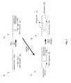
- FIG. 2is a block diagram of an exemplary photonically-enabled process flow with backside etch and metal deposition, in accordance with an embodiment of the invention.
- a photonically enabled process flow 200comprising an original CMOS process 220 , a shallow trench module 203 , a custom implant module 207 , source/drain implants module 213 , a blocking salicidation module 215 , a germanium module 217 , and a data processing module 223 .
- the original CMOS processcomprises a beginning of process flow step 201 , a deep trench module 205 , a well module 209 , a gate module 211 , a back-end metals module 219 , and a wafers out step 221 .
- the photonically-enabled process flowbegins with custom SOI substrates with appropriate oxide thickness for optical processes being inserted into the beginning of process flow step 201 which may comprise suitable wafer preparation processes, such as sorting, cleaning, or quality control, for example.
- the wafersthen proceed to the shallow trench module 203 for defining and etching of shallow trenches.
- the shallow trench module 203may comprise photolithography, etching, fill, and chemical-mechanical polishing (CMP), for example, followed by the deep trench module 205 , which comprises a conventional CMOS trench module.
- the well module 209comprises photolithography steps and dopant ion implantation to define the wells for CMOS devices.
- the custom implants module 207may be inserted into the well module 209 , to define doping regions specific to optoelectronic devices, for example.
- the wafersthen proceed to the gate module 211 to define CMOS gates via photolithography, etching, trimming, spacers, and implants, for example.
- Source and drain implantsmay be performed by the source/drain implant module 213 before proceeding to the blocking salicidation module 215 .
- the salicidation module 215generates a self-aligned silicide layer in the silicon surface for metal contacts, which is followed by the germanium module 217 , which may deposit germanium for integrated photodetectors on the SOI silicon wafers.
- the germanium processmay be fully CMOS compatible.
- the wafersthen proceed to the back-end metals module 219 which comprises a 6-metal low-k copper process, for example, followed by the wafers out step 221 .
- the CMOS process flowcomprises a 0.13 micron CMOS SOI technology platform for integrating guided-wave optics.
- the photolithography processcomprises deep-UV technology to enable near-IR optics capability, and the high resistivity substrate may enable low microwave loss in the circuitry.
- Custom stepsmay be utilized in standard tools, and comprise silicon etch and implant, germanium epitaxy, and may utilize a standard contact module. These processes may be thermal budget compliant, and require no post processing.
- thick Si-layer SOI substratesmay be utilized enabling bulk-like CMOS transistors. This would also enable enhanced optical confinement in optical devices fabricated in the thick Si layer and thus enabling compact photonic devices.
- the backsidemay be etched and a metal reflective layer deposited in the etched trench to improve coupling efficiency of optical devices.
- FIG. 3Ais a block diagram of an exemplary photonically-enabled process flow with double SOI substrates, in accordance with an embodiment of the invention.
- a photonically-enabled process flow 300comprising an original CMOS process 320 , a Si/SiO2 etch module 302 , a shallow/deep trench module 303 , a planarization module 304 , a custom implant module 307 , source/drain implants module 313 , a blocking salicidation module 315 , a germanium module 317 , and a data processing module 323 .
- the original CMOS processcomprises a beginning of process flow step 301 , a deep trench module 305 , a well module 309 , a gate module 311 , a back-end metals module 319 , and a wafers out step 321 .
- the photonically-enabled process flowbegins with custom SOI substrates with appropriate oxide thickness for optical processes being inserted into the beginning of process flow step 301 which may comprise suitable wafer preparation processes, such as sorting, cleaning, or quality control, for example.
- the wafersthen proceed to the Si/SiO 2 etch module 302 where the top Si and oxide layers in a double SOI substrate may be removed in areas corresponding to areas where optical devices are to be defined.
- the shallow/deep trench module 303 and the custom implants module 307may then be utilized to define the optical devices.
- the planarization module 304may be utilized to define a planar surface for the subsequent CMOS module processes such as the deep trench module 305 , which comprises a conventional CMOS trench module.
- the well module 309comprises photolithography steps and dopant ion implantation to define the wells for CMOS devices.
- the custom implants module 307may be inserted into the well module 309 , to define doping regions specific to optoelectronic devices, for example.
- the wafersthen proceed to the gate module 311 to define CMOS gates via photolithography, etching, trimming, spacers, and implants, for example.
- Source and drain implantsmay be performed by the source/drain implant module 313 before proceeding to the blocking salicidation module 315 .
- the salicidation module 315generates a self-aligned silicide layer in the silicon surface for metal contacts, which is followed by the germanium module 317 , which may deposit germanium for integrated photodetectors on the SOI silicon wafers.
- the germanium processmay be fully CMOS compatible.
- the wafersthen proceed to the back-end metals module 319 which comprises a 6-metal low-k copper process, for example, followed by the wafers out step 321 .
- the CMOS process flowcomprises a 0.13 micron CMOS SOI technology platform for integrating guided-wave optics.
- the photolithography processcomprises deep-UV technology to enable near-IR optics capability, and the high resistivity substrate may enable low microwave loss in the circuitry.
- Custom stepsmay be utilized in standard tools, and comprise silicon etch and implant, germanium epitaxy, and may utilize a standard contact module. These processes may be thermal budget compliant, and require no post processing.
- two separate SOI layersmay be utilized to enable layer thicknesses optimized for both optical and electronic devices, with the desired thicker layer utilized for the photonic devices.
- standard CMOS electronics modulesmay be utilized without requiring modified processes to account for tradeoffs between electronic and photonic devices.
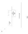
- FIG. 3Bis a block diagram of an exemplary photonically-enabled process flow with different optical and electronic device layer thicknesses, in accordance with an embodiment of the invention.
- a photonically-enabled process flow 350comprising an original CMOS process 320 , a shallow/deep trench module 303 , source/drain implants module 313 , an epitaxy/trench/implant module 314 , a blocking salicidation module 315 , a germanium module 317 , and a data processing module 323 .
- the original CMOS processcomprises a beginning of process flow step 301 , a deep trench module 305 , a well module 309 , a gate module 311 , a back-end metals module 319 , and a wafers out step 321 .
- the photonically-enabled process flowbegins with custom SOI substrates with appropriate oxide thickness for optical processes being inserted into the beginning of process flow step 301 which may comprise suitable wafer preparation processes, such as sorting, cleaning, or quality control, for example.
- the wafersthen proceed to the shallow trench module 303 for defining and etching of shallow trenches.
- the shallow trench module 303may comprise photolithography, etching, fill, and chemical-mechanical polishing (CMP), for example, followed by the deep trench module 305 , which comprises a conventional CMOS trench module.
- the well module 309comprises photolithography steps and dopant ion implantation to define the wells for CMOS devices.
- the wafersthen proceed to the gate module 311 to define CMOS gates via photolithography, etching, trimming, spacers, and implants, for example.
- Source and drain implantsmay be performed by the source/drain implant module 313 before proceeding to the epitaxy/trench/implant module 314 where a thicker Si layer may be deposited for photonic devices.
- further trench and implant stepsmay be performed for the photonic devices in the epitaxy/trench/implant module 314 .
- the salicidation module 315generates a self-aligned silicide layer in the silicon surface for metal contacts, which is followed by the germanium module 317 , which may deposit germanium for integrated photodetectors on the SOI silicon wafers.
- the germanium processmay be fully CMOS compatible.
- the wafersthen proceed to the back-end metals module 319 which comprises a 6-metal low-k copper process, for example, followed by the wafers out step 321 .
- the CMOS process flowcomprises a 0.13 micron CMOS SOI technology platform for integrating guided-wave optics.
- the photolithography processcomprises deep-UV technology to enable near-IR optics capability, and the high resistivity substrate may enable low microwave loss in the circuitry.
- Custom stepsmay be utilized in standard tools, and comprise silicon etch and implant, germanium epitaxy, and may utilize a standard contact module. These processes may be thermal budget compliant, and require no post processing.
- two separate Si layer thicknessesmay be utilized to enable layer thicknesses optimized for both optical and electronic devices, with the desired thicker layer utilized for the photonic devices deposited in the epitaxy/trench/implant module 314 .
- standard CMOS electronics modulesmay be utilized without requiring modified processes to account for tradeoffs between electronic and photonic devices.
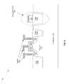
- FIG. 3Cis a block diagram of an exemplary photonically-enabled process flow with wafer/chip bonding, in accordance with an embodiment of the invention.
- a photonically-enabled process flow 360comprising an original CMOS process 320 , an optical CMOS process 330 , and a data processing module 323 .
- the original CMOS process 320may comprise a trench module 305 A, a well module 309 , a gate module 311 , a source/drain implant module 313 , and a back-end metals module 319 A.
- the optical CMOS process process 330may comprise a trench module 303 A, an implant module 307 , a blocking salicidation module 315 , a germanium module 317 , a back-end metals module 319 B, and a wafer/chip bonding module 321 .
- the original CMOS process flow 330begins with standard SOI substrates being inserted into the beginning of process flow step 301 A which may comprise suitable wafer preparation processes, such as sorting, cleaning, or quality control, for example.
- the wafersthen proceed to the trench module 305 A for defining and etching of shallow and/or deep trenches.
- the trench module 305 Amay comprise photolithography, etching, fill, and chemical-mechanical polishing (CMP), for example, before proceeding to the well module 309 .
- CMPchemical-mechanical polishing
- the well module 309comprises photolithography steps and dopant ion implantation to define the wells for CMOS devices.
- the wafersthen proceed to the gate module 311 to define CMOS gates via photolithography, etching, trimming, spacers, and implants, for example.
- Source and drain implantsmay be performed by the source/drain implant module 313 before proceeding to the back-end metals module 319 A.
- the optical CMOS process flow 330begins with custom SOI substrates with appropriate oxide thickness for optical processes being inserted into the beginning of process flow step 301 which may comprise suitable wafer preparation processes, such as sorting, cleaning, or quality control, for example.
- the wafersthen proceed to the trench module 303 A which may comprise photolithography, etching, fill, and chemical-mechanical polishing (CMP), for example, followed by the implant module 307 where dopants appropriate for optical devices may be implanted into the optical wafers.
- CMPchemical-mechanical polishing
- the salicidation module 315generates a self-aligned silicide layer in the silicon surface for metal contacts, which is followed by the germanium module 317 , which may deposit germanium for integrated photodetectors on the SOI silicon wafers.
- the germanium processmay be fully CMOS compatible.
- the wafersthen proceed to the back-end metals module 319 which comprises a 6-metal low-k copper process, for example, followed by the wafers out step 321 .
- the wafers from the optical CMOS process 330may then be bonded to the wafers from the original CMOS process 320 in the wafer/chip bonding module 321 .
- bondingmay be utilized to bond chips as opposed to full wafers.
- a dicing processwould be utilized in the wafer/chip bonding module 321 to generate chips for bonding.
- the CMOS process flow 320comprises a 0.13 micron CMOS SOI technology platform for integrating guided-wave optics.
- the photolithography processcomprises deep-UV technology to enable near-IR optics capability, and the high resistivity substrate may enable low microwave loss in the circuitry.
- Custom stepsmay be utilized in standard tools, and comprise silicon etch and implant, germanium epitaxy, and may utilize a standard contact module. These processes may be thermal budget compliant, and require no post processing.
- CMOS wafer processesmay be utilized to enable wafers optimized for both optical and electronic devices.
- the wafers, or chips,may then be bonded to result in a hybrid structure with increased device performance for both electronic and photonic devices.
- standard CMOS electronics modulesmay be utilized without requiring modified processes to account for tradeoffs between electronic and photonic devices.
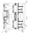
- FIG. 4Ais a cross-section of exemplary integrated electrical and optoelectronic devices, in accordance with an embodiment of the invention.
- an integrated semiconductor structure 400comprising a transistor 410 and optical devices 420 and associated layers.
- the integrated semiconductor structure 400may result from the process flow described with respect to FIG. 2 .
- the layersare utilized to fabricate the transistor 410 and the optical devices 420 , to isolate, and to provide electrical connection to the devices, for example.
- the integrated semiconductor structure 400comprises a silicon substrate 401 , a buried oxide 403 , a silicon layer 405 , a contact layer 415 , a metal 1 layer 417 , a via 1 layer 419 , a metal 2 layer 421 , a last metal layer 423 , a passivation layer 425 , a metal cap 427 , a metal layer 441 , and a Ge-layer 445 .
- the metal 1 layer 417 , the metal 2 layer 421 , the last metal layer, and the metal cap 427provide electrical contact between layers and to electrical and optoelectronics devices, such as the transistor 410 and the optical devices 420 .
- the metal layer 441enables improved efficiencies of optical I/O devices, such as the optical devices 420 , for example.
- the via 1 layer 419 and the contact layer 415also enable electrical contact to the devices while providing electrical isolation between devices by incorporating insulating materials between conductive vias.
- the transistor 410comprises the well 407 , drain and source implant layers 429 A and 429 B, respectively, a gate 431 , and a passivation layer 433 .
- the Si-layer 405may be thick enough that the transistor 410 may be considered a bulk transistor. If the silicon layer thickness is made thick enough, the substrate will look and act like a bulk substrate from the point of the view of the transistors and process, especially at more advanced CMOS nodes where critical dimensions get smaller and smaller, including implant and junction depths, so that there is an optimal thickness at which bulk CMOS compatibility and optimal optical performance may be achieved.
- the well region 407is a doped silicon layer that enables complementary devices to be integrated on the same substrate by creating a layer of opposite doping to that of the region outside the well.
- the source and drain implant layers 429 A and 429 Bmay comprise p-doped silicon, for example.
- the gate 431may comprise metal or polysilicon, for example, that may be isolated from the well 407 by a thin oxide layer (not shown).
- the optical devices 420comprise doped and undoped regions of the Si-layer 405 , a salicide block 413 , doped contact regions 435 and 437 , etched regions 439 , and the Ge-layer 445 .
- the salicide block 413comprises a layer of material to prevent the silicon of the optical devices 420 and other optical devices from being salicided during the standard CMOS process. If silicon in the optical devices was salicided, large optical losses would result. Additionally, the salicide block 413 blocks unwanted implants into the waveguides and other optical devices, which would also cause unwanted loss.
- the salicide block 413may be etched to the Si-layer 405 so that the Ge-layer 445 may be deposited.
- the Ge-layer 445may be utilized in a photodetector device, for example.
- etched regions 439 in the Si-layer 405may be utilized for optical confinement.
- the etch regions 439may be refilled with a low-k dielectric, for example, or may comprise an air gap with no refill material.
- Fill materialmay comprise silicon oxide or oxynitride materials, for example.
- the substrate 401may be backside etched and the metal layer 441 deposited in the etched region to provide a reflective surface for optical devices such as the optical devices 420 , for example.
- FIG. 4Bis a cross-section of exemplary integrated electrical and optoelectronic devices fabricated using a double SOI process, in accordance with an embodiment of the invention.
- an integrated semiconductor structure 430comprising a transistor 410 and optical devices 420 and associated layers.
- the integrated semiconductor structure 430may result from the process flow described with respect to FIG. 3A .
- the layersare utilized to fabricate the transistor 410 and the optical devices 420 , to isolate, and to provide electrical connection to the devices, for example.
- the integrated semiconductor structure 430comprises a silicon substrate 401 , a buried oxide layer 403 A, a double buried oxide layer 403 B, silicon layers 405 A and 405 B, field oxide 409 , a contact layer 415 , a metal 1 layer 417 , a via 1 layer 419 , a metal 2 layer 421 , a last metal layer 423 , a passivation layer 425 , a metal cap 427 , and Ge-layer 445 .
- the metal 1 layer 417 , the metal 2 layer 421 , the last metal layer, and the metal cap 427provide electrical contact between layers and to electrical and optoelectronics devices, such as the transistor 410 and the optical devices 420 .
- the via 1 layer 419 and the contact layer 415also enable electrical contact to the devices while providing electrical isolation between devices by incorporating insulating materials between conductive vias.
- the transistor 410comprises a SOI transistor with source and drain regions formed in the Si-layer comprising the well 407 from dopant implant processes, for example, a gate 431 , and a passivation layer 433 .
- the gate 431may comprise metal or polysilicon, for example, that may be isolated from the well 407 by a thin oxide layer (not shown).
- the optical devices 420comprise doped and/or undoped regions of the Si-layer 405 A, a salicide block 413 , doped contact regions 435 and 437 , etched regions 439 , and the Ge-layer 445 .
- the salicide block 413comprises a layer of material to prevent the silicon of the optical devices 420 and other optical devices from being salicided during the standard CMOS process. If silicon in the optical devices was salicided, large optical losses would result. Additionally, the salicide block 413 blocks unwanted implants into the waveguides and other optical devices, which would also cause unwanted loss.
- the salicide block 413may be etched to the Si-layer 405 A where the Ge-layer 445 may be deposited.
- the Ge-layer 445may be utilized in a photodetector device, for example.
- etched regions 439 in the Si-layer 405 Amay be utilized for optical confinement.
- the etch regions 439may be refilled with a low-k dielectric, for example, or may comprise an air gap with no refill material.
- Fill materialmay comprise silicon oxide or oxynitride materials, for example.
- a double-SOI substrate with two Si-layer thicknessesmay be utilized to provide appropriate layer thicknesses for both optical and electronic devices in the CMOS process. Accordingly, a thicker Si-layer 405 A for improved optical devices may be introduced beneath the thinner Si-layer 405 B for standard CMOS electronic device processes.
- the electronic devicesare on top of the optical devices such that the optical device processes do not affect the electronic device performance.
- the optical device processesmay be designed taking into account the subsequent electronic device processes to take place.
- the optical devicesmay be fabricated on top of the electronic devices, but this may alter the performance of the standard CMOS electronic devices.
- FIG. 4Cis a cross-section of exemplary integrated electrical and optoelectronic devices fabricated using two silicon layer thicknesses, in accordance with an embodiment of the invention.
- an integrated semiconductor structure 440comprising a transistor 410 and optical devices 420 and associated layers.
- the integrated semiconductor structure 440may result from the process flow described with respect to FIG. 3B .
- the layersare utilized to fabricate the transistor 410 and the optical devices 420 , to isolate, and to provide electrical connection to the devices, for example.
- the integrated semiconductor structure 440comprises a silicon substrate 401 , a buried oxide layer 403 , a well 407 , a silicon layer 407 B, a contact layer 415 , a metal 1 layer 417 , a via 1 layer 419 , a metal 2 layer 421 , a last metal layer 423 , a passivation layer 425 , and a metal cap 427 .
- the metal 1 layer 417 , the metal 2 layer 421 , the last metal layer, and the metal cap 427provide electrical contact between layers and to electrical and optoelectronics devices, such as the transistor 410 and the optical devices 420 .
- the via 1 layer 419 and the contact layer 415also enable electrical contact to the devices while providing electrical isolation between devices by incorporating insulating materials between conductive vias.
- the transistor 410comprises a SOI transistor with source and drain regions formed in the well 407 from dopant implant processes, for example, a gate 431 , and a passivation layer 433 .
- the gate 431may comprise metal or polysilicon, for example, that may be isolated from the well 407 by a thin oxide layer (not shown).
- the optical devices 420comprises doped and/or undoped regions of the Si-layer 407 B, a salicide block 413 , doped contact regions 435 and 437 , etched regions 439 , and the Ge-layer 445 .
- the salicide block 413comprises a layer of material to prevent the silicon of the optical devices 420 and other optical devices from being salicided during the standard CMOS process. If silicon in the optical devices was salicided, large optical losses would result. Additionally, the salicide block 413 blocks unwanted implants into the waveguides and other optical devices, which would also cause unwanted loss.
- the salicide block 413may be etched to the Si-layer 407 B where the Ge-layer 445 may be deposited.
- the Ge-layer 445may be utilized in a photodetector device, for example.
- etched regions 439 in the Si-layer 405may be utilized for optical confinement.
- the etch regions 439may be refilled with a low-k dielectric, for example, or may comprise an air gap with no refill material.
- Fill materialmay comprise silicon oxide or oxynitride materials, for example.
- silicon layers of different thicknessmay be deposited in the same deposition process, such as by selective area growth, for example.
- Si-layer thicknessesmay be configured for the particular device.
- the Si-layer 407 B in the optical devices 420may be thicker than the Si-layer 407 A in the transistor 410 since optical devices may require thicker layers for better optical confinement, while resulting in Si-layer thicknesses used in standard CMOS electronics processes.
- a thick Si-layermay be grown, and regions corresponding to electronic devices may be thinned.
- FIG. 4Dis a cross-section of exemplary integrated electrical and optoelectronic devices fabricated using wafer/chip bonding, in accordance with an embodiment of the invention.
- an integrated semiconductor structure 450comprising a CMOS photonics substrate/chip 450 , a CMOS electronics substrate/chip 460 , and the metal cap layer 427 for substrate/chip physical and electrical coupling.
- the CMOS photonics substrate/chip 450comprises optical devices 420 and associated layers
- the CMOS electronics substrate/chip 460comprises transistors 410 A and 410 B and associated layers.
- the integrated semiconductor structure 440may result from the process flow described with respect to FIG. 3C .
- the layersare utilized to fabricate the transistors 410 A and 410 B and the optical devices 420 , to isolate, and to provide electrical connection to the devices, for example.
- the CMOS photonics substrate/chip 450comprises a substrate 401 A, a buried oxide 403 , a Si-layer 405 , a contact layer 415 A, a metal 1 layer 417 A, and through-silicon vias (TSVs) 443 A and 443 B.
- the optical devices 420comprise doped and/or undoped regions of the Si-layer 405 , a salicide block 413 , doped contact regions 435 and 437 , etched region 439 , and the Ge-layer 445 .
- the salicide block 413comprises a layer of material to prevent the silicon of the optical devices 420 and other optical devices from being salicided during the standard CMOS process. If silicon in the optical devices was sailcided, large optical losses would result.
- the salicide block 413blocks unwanted implants into the waveguides and other optical devices, which would also cause unwanted loss.
- the salicide block 413may be etched to the Si-layer 405 so that the Ge-layer 445 may be deposited.
- the Ge-layer 445may be utilized in a photodetector device, for example.
- etched regions 439 in the Si-layer 405may be utilized for optical confinement.
- the etch regions 439may be refilled with a low-k dielectric, for example, or may comprise an air gap with no refill material.
- Fill materialmay comprise silicon oxide or oxynitride materials, for example.
- the CMOS electronics substrate/chip 460comprises a silicon substrate 401 B, a well 407 , a contact layer 415 B, a metal 1 layer 417 B, a last metal layer 423 , a passivation layer 425 , and the metal cap 427 .
- the metal 1 layer 417 B, the last metal layer 423 , and the metal cap 427provide electrical contact between layers and to electrical and optoelectronics devices, such as the transistors 410 A and 410 B and the optical devices 420 .
- the contact layer 415also enables electrical contact to the devices while providing electrical isolation between devices by incorporating insulating materials between conductive vias.
- the transistors 410 A and 410 Bcomprise bulk transistors with source and drain regions formed in the well 407 or the substrate 401 B, respectively, from dopant implant processes, for example, as well as a gate 431 , and a passivation layer 433 .
- the gate 431may comprise metal or polysilicon, for example, that may be isolated from the well 407 by a thin oxide layer (not shown).
- CMOS processesmay be utilized to fabricate the CMOS photonics substrate/chip 450 and the CMOS electronics substrate/chip 460 so that the processes may be optimized for each type of device.
- the wafers, or alternatively diced chips,may then be bonded together to form an optoelectronic hybrid module.
- layer thicknesses and doping levelsmay be configured for the best electronic and photonic performance in the respective structure without the tradeoffs in performance associated with fabricating electronic and photonic structures concurrently.
- FIG. 5is a diagram illustrating an exemplary structure utilizing a shallow trench as a bottom cladding, in accordance with an embodiment of the invention.
- integrated electronic and photonic structure 500comprising a transistor 511 and a waveguide device 510 integrated in the Si substrate 513 .
- the transistor 511comprises contacts 501 , a gate 503 , oxide layers 505 A and 505 B, source 507 and drain 509 .
- the contacts 501comprise metal and/or other conductive material for electrical contact to the transistor 511 .
- the source 507 and drain 509may be formed via implantation of dopant material into a silicon layer in the substrate 513 , for example.
- the waveguide devicecomprises deposited Si 515 and oxide layer 505 C.
- LOCOSlocal formation of oxide
- silicon or another material of higher indexsuch as silicon nitride or silicon oxynitride
- silicon nitride or silicon oxynitridemay be deposited and patterned over the field oxide, resulting in the deposited Si 515 . If silicon is deposited, it typically will not result in crystalline silicon, but either poly-silicon or amorphous silicon. Subsequent processes may improve the quality of the silicon, such as thermal annealing or laser treatment. If silicon nitride is used, it is generally used to fabricate passive optical devices like waveguides and couplers, but not active devices like modulators.
- photodetectionmay be provided by growing a Ge photodetector directly on silicon and butt-coupling a silicon or silicon nitride waveguide directly into the Ge area.
- FIG. 6is a diagram illustrating an exemplary epitaxial lateral overgrowth optical device, in accordance with an embodiment of the invention.
- a rib waveguide 600comprising an epitaxial lateral overgrowth (ELO) Si layer 601 , a shallow trench isolation oxide 603 , and a Si substrate 605 .
- ELOepitaxial lateral overgrowth
- silicon materialmay be deposited utilizing lateral epitaxial overgrowth (ELO) to form a photonic device in a small area over the field oxide, namely the shallow trench isolation oxide 603 .
- the ELO Si layer 601may be patterned to form a rib waveguide that may be nearly equivalent to a crystalline silicon waveguide in the substrate. In this manner, most silicon based optical devices may be fabricated.
- FIG. 7is a diagram illustrating exemplary cladding formation by removal of silicon, in accordance with an embodiment of the invention. Referring to FIG. 7 , there is shown a deposited Si layer 701 A, a SiGe layer 703 , and Si substrate 705 processed through the steps 700 , 720 , 740 , and 760 .
- step 700there is shown the Si substrate 705 with the deposited Si layer 701 A over the SiGe layer 703 .
- SiGemay be selectively etched when the Ge content is at least a few percent over Si.
- the SiGe layer 703is deposited locally over the Si substrate 705 in the areas where the photonic devices are desired. Silicon may then be grown over the entire wafer, or only locally, encompassing the areas where SiGe has been deposited.
- step 720the deposited Si 701 A may be etched locally down to the SiGe layer 703 , followed by step 740 where a selective SiGe etch may be utilized to remove the SiGe area.
- a selective SiGe etchmay be utilized to remove the SiGe area.
- the air cladding 707provides the index contrast needed to form a waveguide.
- the remaining siliconcan be processed to form waveguides and other optical devices.
- FIG. 8is a diagram illustrating exemplary oxide formation through oxygen implant and thermal treatment, in accordance with an embodiment of the invention.
- SiO 2 formation processcomprising steps 800 and 802 which comprise a Si substrate 801 , a mask 803 , an O 2 -implanted Si layer 805 , and an SiO 2 layer 807 .
- O 2may be implanted in the Si substrate 801 through openings in the mask 803 , thereby forming the O 2 -implanted Si layer 805 , as shown in step 800 .
- a thermal treatment of the O 2 -implanted Si layer 805generates the SiO 2 layer 807 shown in step 820 . Accordingly, this process may be utilized to form optical cladding layers at an appropriate distance below the Si surface, thereby enabling optical confinement.
- SiO 2 layer 807also provides etch selectivity to silicon and may be used to form other optical devices.
- FIG. 9is a diagram illustrating exemplary backside etch structures, in accordance with an embodiment of the invention. Referring to FIG. 9 , there is shown alternative backside etched devices 900 and 920 .
- the backside etched device 900comprises a Si substrate 901 and an optical device 910 .
- Silicon substratesare typically hundreds of microns thick and the thickness desired for an integrated optical device approximately 1 micron or less, indicating that a timed etch is generally not capable of leaving a controlled amount of silicon with such a starting thickness.
- One method in forming a backside claddingis to locally remove silicon from the substrate and leave only the thickness of silicon desired via etching, as shown in the backside etched device 900 .
- An alternativeis to polish the backside of the substrate to a much smaller thickness, leaving approximately 100 microns or less of silicon, which is still much larger than the final desired thickness and thus precludes a timed etch.
- An alternative etching methodis to utilize local implantation of oxygen and thermal treatment in the areas where photonic devices are desired, as described with respect to FIG. 8 , to provide an etch stop layer.
- the O 2 -implanted Si layer 905is transformed into the SiO 2 layer 907 with thermal treatment.
- the SiO 2 layer 907then acts as an etch stop layer, precluding the need for a precise etch time and controlled etch rate.
- a fast etchmay be used to remove most of the silicon, followed by a different etch to accurately remove the remaining silicon and stop on the oxide or SiGe etch stop layer.
- the backside holemay either be left as is, with air providing the bottom cladding for a waveguide, or it may be refilled with a low index material, such as silicon dioxide or other low-k dielectric.
- a low index materialsuch as silicon dioxide or other low-k dielectric.
- heavy implantation of silicon with p- or n-type implantsmay be utilized to provide selectivity in etch to nominally undoped silicon.
- FIG. 10is a diagram illustrating an exemplary backside etch structure, in accordance with an embodiment of the invention. Referring to FIG. 10 , there is shown steps 1000 and 1020 comprising a deposited Si-layer 1001 A, a SiGe layer 1003 , a Si substrate 1005 , a deposited and processed Si-layer 1001 A.
- Step 1000illustrates the deposited Si-layer 1001 A on the SiGe layer 1003 deposited on the Si substrate 1005 .
- Step 1020illustrates an optical device fabricated in the deposited Si-layer 1001 A and the backside of the Si-substrate 1005 etched utilizing the SiGe as an etch stop.
- FIG. 11is a diagram illustrating an exemplary backside etch structure with metal mirror, in accordance with an embodiment of the invention.
- backside etched photonic device 1100comprising a Si substrate 1101 , a SiO 2 refill layer 1103 , a metal mirror 1105 , and a grating structure 1107 .
- the Si substratemay be backside etched and refilled with SiO 2 to form the SiO 2 refill layer 1103 .
- desired optical confinementmay be obtained for optical devices integrated in the Si substrate 1101 .
- a metal layermay be deposited, the metal mirror 1105 , which may provide improved performance in grating coupler-like devices, such as increased confinement of optical modes.
- photonic and electronic devicesmay be fabricated on a single complementary metal-oxide semiconductor (CMOS) wafer 401 with different silicon layer thicknesses 405 A/ 405 B for the photonic and the electronic devices 420 and 410 , respectively.
- CMOScomplementary metal-oxide semiconductor
- the electronic and photonic devices 410 and 420may be fabricated on a semiconductor-on-insulator (SOI) wafer 401 utilizing a bulk CMOS process.
- SOIsemiconductor-on-insulator
- the electronic and photonic 410 and 420 devicesmay be fabricated on a SOI wafer utilizing a SOI CMOS process.
- the different silicon layer thicknessesmay be fabricated utilizing a double SOI process 300 and/or a selective area growth process 314 .
- Cladding layers 807 / 907 for the photonic devicesmay be fabricated utilizing one or more oxygen implants into the CMOS wafer and/or utilizing CMOS trench oxide 505 C/ 603 on the CMOS wafer.
- Silicon material 515 for the photonic devicesmay be deposited on the CMOS trench oxide 505 C utilizing epitaxial lateral overgrowth.
- Cladding layers for the photonic devicesmay be fabricated utilizing selective backside etching regions of the CMOS wafer below the photonic devices. Reflective surfaces for the photonic devices may be fabricated by depositing metal 1105 on the selectively etched regions of the CMOS wafer.
- Silicon dioxide 907 integrated in the CMOS wafer using oxygen implantmay be utilized as an etch stop layer for the backside etching.
- Silicon germanium 1003 integrated in the CMOS wafermay be utilized as an etch stop layer for the backside etching.
- Photonic and electronic devicesmay be fabricated on two complementary metal-oxide semiconductor (CMOS) wafers 450 and 460 with different silicon layer thicknesses for the photonic and the electronic devices by bonding at least a portion of each of the wafers together, where one of the CMOS wafers comprises the photonic devices and the other CMOS wafer comprises the electronic devices.
- CMOScomplementary metal-oxide semiconductor
Landscapes
- Physics & Mathematics (AREA)
- Electromagnetism (AREA)
- Engineering & Computer Science (AREA)
- Computer Networks & Wireless Communication (AREA)
- Signal Processing (AREA)
- Metal-Oxide And Bipolar Metal-Oxide Semiconductor Integrated Circuits (AREA)
- Thin Film Transistor (AREA)
- Solid State Image Pick-Up Elements (AREA)
- Optical Integrated Circuits (AREA)
- Light Receiving Elements (AREA)
Abstract
Description
Claims (24)
Priority Applications (24)
| Application Number | Priority Date | Filing Date | Title |
|---|---|---|---|
| US12/554,449US8877616B2 (en) | 2008-09-08 | 2009-09-04 | Method and system for monolithic integration of photonics and electronics in CMOS processes |
| CN2013100737653ACN103187369A (en) | 2008-09-08 | 2009-09-08 | Monolithic integration of photonics and electronics in cmos processes |
| CN2009801392568ACN102171606A (en) | 2008-09-08 | 2009-09-08 | Monolithic Integration of Photonic and Electronic Components in CMOS Technology |
| EP09812368.0AEP2326988B1 (en) | 2008-09-08 | 2009-09-08 | Monolithic integration of photonics and electronics in cmos processes |
| EP18204690.4AEP3534209B1 (en) | 2008-09-08 | 2009-09-08 | Monolithic integration of photonics and electronics in cmos processes |
| PCT/US2009/056213WO2010028355A1 (en) | 2008-09-08 | 2009-09-08 | Monolithic integration of photonics and electronics in cmos processes |
| CN201310073121.4ACN103219292B (en) | 2008-09-08 | 2009-09-08 | Single-chip integration photonic element and electronic component in CMOS technology |
| TW098130258ATWI503890B (en) | 2008-09-08 | 2009-09-08 | Method and system for integrating photons and electrons by single stone in complementary metal oxide semiconductor process |
| TW104121889ATWI550780B (en) | 2008-09-08 | 2009-09-08 | Method and system for integrating photons and electrons by single stone in complementary metal oxide semiconductor process |
| CN201611025934.6ACN107039350B (en) | 2008-09-08 | 2009-09-08 | Monolithic integration of photonic and electronic components in CMOS processes |
| US13/364,845US9053980B2 (en) | 2008-09-08 | 2012-02-02 | Monolithic integration of photonics and electronics in CMOS processes |
| US13/364,909US8895413B2 (en) | 2008-09-08 | 2012-02-02 | Monolithic integration of photonics and electronics in CMOS processes |
| US13/422,776US8831437B2 (en) | 2009-09-04 | 2012-03-16 | Method and system for a photonic interposer |
| US13/568,406US9331096B2 (en) | 2009-09-04 | 2012-08-07 | Method and system for hybrid integration of optical communication systems |
| US14/475,484US9356701B2 (en) | 2008-09-08 | 2014-09-02 | Method and system for a photonic interposer |
| US14/729,826US10256908B2 (en) | 2008-09-08 | 2015-06-03 | Method and system for monolithic integration of photonics and electronics in CMOS processes |
| US15/144,611US9625665B2 (en) | 2009-09-04 | 2016-05-02 | Method and system for hybrid integration of optical communication systems |
| US15/165,677US9813161B2 (en) | 2008-09-08 | 2016-05-26 | Method and system for photonic interposer |
| US15/487,770US9829661B2 (en) | 2009-09-04 | 2017-04-14 | Method and system for hybrid integration of optical communication systems |
| US15/796,063US10122463B2 (en) | 2008-09-08 | 2017-10-27 | Method and system for a photonic interposer |
| US15/818,352US20180074270A1 (en) | 2009-09-04 | 2017-11-20 | Method And System For Hybrid Integration Of Optical Communication Systems |
| US16/180,715US10374719B2 (en) | 2008-09-08 | 2018-11-05 | Method and system for a photonic interposer |
| US16/378,119US11438065B2 (en) | 2008-09-08 | 2019-04-08 | Method and system for monolithic integration of photonics and electronics in CMOS processes |
| US16/533,541US10873399B2 (en) | 2008-09-08 | 2019-08-06 | Method and system for a photonic interposer |
Applications Claiming Priority (3)
| Application Number | Priority Date | Filing Date | Title |
|---|---|---|---|
| US19147908P | 2008-09-08 | 2008-09-08 | |
| US19935308P | 2008-11-14 | 2008-11-14 | |
| US12/554,449US8877616B2 (en) | 2008-09-08 | 2009-09-04 | Method and system for monolithic integration of photonics and electronics in CMOS processes |
Related Child Applications (5)
| Application Number | Title | Priority Date | Filing Date |
|---|---|---|---|
| US13/364,845DivisionUS9053980B2 (en) | 2008-09-08 | 2012-02-02 | Monolithic integration of photonics and electronics in CMOS processes |
| US13/364,845ContinuationUS9053980B2 (en) | 2008-09-08 | 2012-02-02 | Monolithic integration of photonics and electronics in CMOS processes |
| US13/364,909DivisionUS8895413B2 (en) | 2008-09-08 | 2012-02-02 | Monolithic integration of photonics and electronics in CMOS processes |
| US13/422,776Continuation-In-PartUS8831437B2 (en) | 2008-09-08 | 2012-03-16 | Method and system for a photonic interposer |
| US13/568,406Continuation-In-PartUS9331096B2 (en) | 2009-09-04 | 2012-08-07 | Method and system for hybrid integration of optical communication systems |
Publications (2)
| Publication Number | Publication Date |
|---|---|
| US20100059822A1 US20100059822A1 (en) | 2010-03-11 |
| US8877616B2true US8877616B2 (en) | 2014-11-04 |
Family
ID=41797547
Family Applications (5)
| Application Number | Title | Priority Date | Filing Date |
|---|---|---|---|
| US12/554,449Active2031-11-28US8877616B2 (en) | 2008-09-08 | 2009-09-04 | Method and system for monolithic integration of photonics and electronics in CMOS processes |
| US13/364,845ActiveUS9053980B2 (en) | 2008-09-08 | 2012-02-02 | Monolithic integration of photonics and electronics in CMOS processes |
| US13/364,909ActiveUS8895413B2 (en) | 2008-09-08 | 2012-02-02 | Monolithic integration of photonics and electronics in CMOS processes |
| US14/729,826Active2030-03-08US10256908B2 (en) | 2008-09-08 | 2015-06-03 | Method and system for monolithic integration of photonics and electronics in CMOS processes |
| US16/378,119Active2030-11-04US11438065B2 (en) | 2008-09-08 | 2019-04-08 | Method and system for monolithic integration of photonics and electronics in CMOS processes |
Family Applications After (4)
| Application Number | Title | Priority Date | Filing Date |
|---|---|---|---|
| US13/364,845ActiveUS9053980B2 (en) | 2008-09-08 | 2012-02-02 | Monolithic integration of photonics and electronics in CMOS processes |
| US13/364,909ActiveUS8895413B2 (en) | 2008-09-08 | 2012-02-02 | Monolithic integration of photonics and electronics in CMOS processes |
| US14/729,826Active2030-03-08US10256908B2 (en) | 2008-09-08 | 2015-06-03 | Method and system for monolithic integration of photonics and electronics in CMOS processes |
| US16/378,119Active2030-11-04US11438065B2 (en) | 2008-09-08 | 2019-04-08 | Method and system for monolithic integration of photonics and electronics in CMOS processes |
Country Status (5)
| Country | Link |
|---|---|
| US (5) | US8877616B2 (en) |
| EP (2) | EP2326988B1 (en) |
| CN (4) | CN102171606A (en) |
| TW (2) | TWI550780B (en) |
| WO (1) | WO2010028355A1 (en) |
Cited By (12)
| Publication number | Priority date | Publication date | Assignee | Title |
|---|---|---|---|---|
| US20110206322A1 (en)* | 2010-02-23 | 2011-08-25 | Daniel Kucharski | Method and System for Implementing High-Speed Interfaces Between Semiconductor Dies in Optical Communication Systems |
| US9864138B2 (en) | 2015-01-05 | 2018-01-09 | The Research Foundation For The State University Of New York | Integrated photonics including germanium |
| US10698156B2 (en) | 2017-04-27 | 2020-06-30 | The Research Foundation For The State University Of New York | Wafer scale bonded active photonics interposer |
| US10816724B2 (en) | 2018-04-05 | 2020-10-27 | The Research Foundation For The State University Of New York | Fabricating photonics structure light signal transmission regions |
| US10877300B2 (en) | 2018-04-04 | 2020-12-29 | The Research Foundation For The State University Of New York | Heterogeneous structure on an integrated photonics platform |
| US10976491B2 (en) | 2016-11-23 | 2021-04-13 | The Research Foundation For The State University Of New York | Photonics interposer optoelectronics |
| US11029466B2 (en) | 2018-11-21 | 2021-06-08 | The Research Foundation For The State University Of New York | Photonics structure with integrated laser |
| US11114818B2 (en)* | 2018-06-08 | 2021-09-07 | Commissariat A L'energie Atomique Et Aux Energies Alternatives | Photonic chip passed through by a via |
| US11227790B1 (en) | 2019-06-11 | 2022-01-18 | Ciena Corporation | Managing trench depth in integrated systems |
| US11502214B2 (en) | 2021-03-09 | 2022-11-15 | Globalfoundries U.S. Inc. | Photodetectors used with broadband signal |
| US11550099B2 (en) | 2018-11-21 | 2023-01-10 | The Research Foundation For The State University Of New York | Photonics optoelectrical system |
| US12366705B2 (en) | 2018-11-21 | 2025-07-22 | The Research Foundation For The State Univeristy Of Newyork | Photonics optoelectrical system |
Families Citing this family (85)
| Publication number | Priority date | Publication date | Assignee | Title |
|---|---|---|---|---|
| FR2911721B1 (en)* | 2007-01-19 | 2009-05-01 | St Microelectronics Crolles 2 | MOSFET DEVICE ON SELF |
| US7955887B2 (en) | 2008-06-03 | 2011-06-07 | International Business Machines Corporation | Techniques for three-dimensional circuit integration |
| US7897428B2 (en)* | 2008-06-03 | 2011-03-01 | International Business Machines Corporation | Three-dimensional integrated circuits and techniques for fabrication thereof |
| US8877616B2 (en) | 2008-09-08 | 2014-11-04 | Luxtera, Inc. | Method and system for monolithic integration of photonics and electronics in CMOS processes |
| US8831437B2 (en) | 2009-09-04 | 2014-09-09 | Luxtera, Inc. | Method and system for a photonic interposer |
| US8853745B2 (en)* | 2009-01-20 | 2014-10-07 | Raytheon Company | Silicon based opto-electric circuits |
| US11181688B2 (en) | 2009-10-13 | 2021-11-23 | Skorpios Technologies, Inc. | Integration of an unprocessed, direct-bandgap chip into a silicon photonic device |
| US8630326B2 (en) | 2009-10-13 | 2014-01-14 | Skorpios Technologies, Inc. | Method and system of heterogeneous substrate bonding for photonic integration |
| US9882073B2 (en) | 2013-10-09 | 2018-01-30 | Skorpios Technologies, Inc. | Structures for bonding a direct-bandgap chip to a silicon photonic device |
| US8805130B2 (en) | 2010-03-16 | 2014-08-12 | Cornell University | Semiconductor high-speed integrated electro-optic devices and methods |
| KR101683770B1 (en)* | 2010-07-28 | 2016-12-08 | 삼성전자주식회사 | Method for manufacturing photodetector structure |
| US8824837B2 (en) | 2010-08-26 | 2014-09-02 | The Board Of Trustees Of The Leland Stanford Junior University | Integration of optoelectronics with waveguides using interposer layer |
| CN102097432A (en)* | 2010-10-12 | 2011-06-15 | 上海宏力半导体制造有限公司 | Semiconductor device and manufacturing method thereof |
| US8633067B2 (en) | 2010-11-22 | 2014-01-21 | International Business Machines Corporation | Fabricating photonics devices fully integrated into a CMOS manufacturing process |
| US9922967B2 (en) | 2010-12-08 | 2018-03-20 | Skorpios Technologies, Inc. | Multilevel template assisted wafer bonding |
| TWI416706B (en)* | 2010-12-20 | 2013-11-21 | Univ Nat Chiao Tung | Electrostatic discharge protection structure of three-dimensional integrated circuit |
| WO2012106686A2 (en)* | 2011-02-04 | 2012-08-09 | Price Lucinda | Color storage and transmission systems and methods |
| US8872345B2 (en)* | 2011-07-07 | 2014-10-28 | Taiwan Semiconductor Manufacturing Company, Ltd. | Forming grounded through-silicon vias in a semiconductor substrate |
| KR101750742B1 (en)* | 2011-10-14 | 2017-06-28 | 삼성전자주식회사 | Photodetector structure |
| US8580635B2 (en)* | 2011-12-05 | 2013-11-12 | International Business Machines Corporation | Method of replacing silicon with metal in integrated circuit chip fabrication |
| US8901576B2 (en)* | 2012-01-18 | 2014-12-02 | International Business Machines Corporation | Silicon photonics wafer using standard silicon-on-insulator processes through substrate removal or transfer |
| CN104137262B (en) | 2012-01-18 | 2015-11-25 | 斯考皮欧技术有限公司 | Vertical Integration of CMOS Electronics and Photonics |
| TWI686904B (en)* | 2012-03-16 | 2020-03-01 | 美商樂仕特拉公司 | Method and system for a photonic interposer |
| US8772902B2 (en) | 2012-04-19 | 2014-07-08 | International Business Machines Corporation | Fabrication of a localized thick box with planar oxide/SOI interface on bulk silicon substrate for silicon photonics integration |
| US9874688B2 (en) | 2012-04-26 | 2018-01-23 | Acacia Communications, Inc. | Co-packaging photonic integrated circuits and application specific integrated circuits |
| US9557478B2 (en)* | 2012-08-28 | 2017-01-31 | Acacia Communications, Inc. | Electronic and optical co-packaging of coherent transceiver |
| EP2703858B1 (en)* | 2012-08-31 | 2017-02-01 | Universität Stuttgart | High-efficient CMOS-compatible grating couplers with backside metal mirror |
| US10094988B2 (en)* | 2012-08-31 | 2018-10-09 | Micron Technology, Inc. | Method of forming photonics structures |
| WO2014062211A1 (en) | 2012-10-19 | 2014-04-24 | Massachusetts Institute Of Technology | Devices and techniques for integrated optical data communication |
| US9236287B2 (en) | 2012-11-02 | 2016-01-12 | GLOBALFOUNDIES Inc. | Fabrication of localized SOI on localized thick box lateral epitaxial realignment of deposited non-crystalline film on bulk semiconductor substrates for photonics device integration |
| US10025120B2 (en) | 2012-12-13 | 2018-07-17 | Luxtera, Inc. | Method and system for a low parasitic silicon high-speed phase modulator having raised fingers perpendicular to the PN junction |
| US8652934B1 (en)* | 2012-12-26 | 2014-02-18 | Micron Technology, Inc. | Semiconductor substrate for photonic and electronic structures and method of manufacture |
| US9036959B2 (en) | 2013-01-02 | 2015-05-19 | International Business Machines Corporation | Intergrating a silicon photonics photodetector with CMOS devices |
| US8796747B2 (en) | 2013-01-08 | 2014-08-05 | International Business Machines Corporation | Photonics device and CMOS device having a common gate |
| US8802484B1 (en)* | 2013-01-22 | 2014-08-12 | Globalfoundries Singapore Pte. Ltd. | Integration of germanium photo detector in CMOS processing |
| US9005458B2 (en) | 2013-02-26 | 2015-04-14 | Micron Technology, Inc. | Photonic device structure and method of manufacture |
| US10048518B2 (en)* | 2013-03-19 | 2018-08-14 | Luxtera, Inc. | Method and system for a low-voltage integrated silicon high-speed modulator |
| US9541775B2 (en)* | 2013-03-19 | 2017-01-10 | Luxtera, Inc. | Method and system for a low-voltage integrated silicon high-speed modulator |
| US9530905B2 (en)* | 2014-11-18 | 2016-12-27 | W&Wsens Devices, Inc. | Microstructure enhanced absorption photosensitive devices |
| CN105556680B (en) | 2013-05-22 | 2017-12-22 | 王士原 | Microstructure-enhanced absorption photosensitive device |
| US10700225B2 (en) | 2013-05-22 | 2020-06-30 | W&Wsens Devices, Inc. | Microstructure enhanced absorption photosensitive devices |
| US11121271B2 (en) | 2013-05-22 | 2021-09-14 | W&WSens, Devices, Inc. | Microstructure enhanced absorption photosensitive devices |
| US10446700B2 (en) | 2013-05-22 | 2019-10-15 | W&Wsens Devices, Inc. | Microstructure enhanced absorption photosensitive devices |
| US10468543B2 (en) | 2013-05-22 | 2019-11-05 | W&Wsens Devices, Inc. | Microstructure enhanced absorption photosensitive devices |
| US9105701B2 (en)* | 2013-06-10 | 2015-08-11 | Micron Technology, Inc. | Semiconductor devices having compact footprints |
| WO2015050168A1 (en)* | 2013-10-02 | 2015-04-09 | 技術研究組合光電子融合基盤技術研究所 | Optical receiving circuit and method for manufacturing same |
| US9299768B2 (en)* | 2013-10-06 | 2016-03-29 | Taiwan Semiconductor Manufacturing Company Limited | Semiconductor device with non-linear surface |
| US9184191B2 (en)* | 2013-10-17 | 2015-11-10 | Micron Technology, Inc. | Method providing an epitaxial photonic device having a reduction in defects and resulting structure |
| WO2015108589A2 (en)* | 2013-10-22 | 2015-07-23 | Massachusetts Institute Of Technology | Waveguide formation using cmos fabrication techniques |
| US9418915B2 (en) | 2014-01-16 | 2016-08-16 | Samsung Electronics Co., Ltd. | Semiconductor device and method for fabricating the same |
| US9431339B2 (en) | 2014-02-19 | 2016-08-30 | International Business Machines Corporation | Wiring structure for trench fuse component with methods of fabrication |
| US9311442B2 (en) | 2014-04-25 | 2016-04-12 | Globalfoundries Inc. | Net-voltage-aware optical proximity correction (OPC) |
| US9385022B2 (en) | 2014-05-21 | 2016-07-05 | Globalfoundries Inc. | Silicon waveguide on bulk silicon substrate and methods of forming |
| US9461090B2 (en) | 2014-07-03 | 2016-10-04 | Globalfoundries Inc. | Photodetector and method of forming the photodetector on stacked trench isolation regions |
| SG10201805058VA (en) | 2014-10-29 | 2018-07-30 | Acacia Communications Inc | Optoelectronic ball grid array package with fiber |
| TWI624705B (en)* | 2015-03-12 | 2018-05-21 | 山姆科技公司 | Optical module including silicon photonics chip and coupler chip |
| US9362444B1 (en)* | 2015-03-18 | 2016-06-07 | International Business Machines Corporation | Optoelectronics and CMOS integration on GOI substrate |
| US9874693B2 (en) | 2015-06-10 | 2018-01-23 | The Research Foundation For The State University Of New York | Method and structure for integrating photonics with CMOs |
| US9356163B1 (en) | 2015-06-16 | 2016-05-31 | International Business Machines Corporation | Structure and method of integrating waveguides, photodetectors and logic devices |
| US20170017050A1 (en) | 2015-07-15 | 2017-01-19 | Lumentum Operations Llc | Optical transmitter assembly for vertical coupling |
| WO2017019013A1 (en)* | 2015-07-27 | 2017-02-02 | Hewlett Packard Enterprise Development Lp | Doped absorption devices |
| US9786641B2 (en) | 2015-08-13 | 2017-10-10 | International Business Machines Corporation | Packaging optoelectronic components and CMOS circuitry using silicon-on-insulator substrates for photonics applications |
| US20170054039A1 (en)* | 2015-08-20 | 2017-02-23 | Globalfoundries Singapore Pte. Ltd. | Photonic devices with through dielectric via interposer |
| DE112015006942T5 (en)* | 2015-09-25 | 2018-06-14 | Intel Corporation | Double-sided metallization with a distributed through the silicon power supply |
| US9673275B2 (en)* | 2015-10-22 | 2017-06-06 | Qualcomm Incorporated | Isolated complementary metal-oxide semiconductor (CMOS) devices for radio-frequency (RF) circuits |
| US10037982B2 (en)* | 2016-01-04 | 2018-07-31 | Infinera Corporation | Photonic integrated circuit package |
| US10120148B2 (en) | 2016-11-01 | 2018-11-06 | Hewlett Packard Enterprise Development Lp | Devices with optical ports in fan-out configurations |
| JP2019012120A (en)* | 2017-06-29 | 2019-01-24 | ルネサスエレクトロニクス株式会社 | Semiconductor device and manufacturing method thereof |
| CN110068894B (en)* | 2018-01-22 | 2020-05-12 | 中国科学院半导体研究所 | Three-dimensional photoelectric integrated grating coupler realized based on CMOS (complementary metal oxide semiconductor) post-process and preparation method |
| WO2019165414A1 (en)* | 2018-02-26 | 2019-08-29 | Arizona Board Of Regents On Behalf Of The University Of Arizona | Fabrication of polymer waveguide interconnect between chips with a gap and/or step |
| US10712497B2 (en) | 2018-02-27 | 2020-07-14 | Samsung Electronics Co., Ltd. | Photonic integrated circuit packages and methods of manufacturing the same |
| US10861804B2 (en) | 2018-03-29 | 2020-12-08 | Taiwan Semiconductor Manufacturing Co., Ltd. | Devices and methods for enhancing insertion loss performance of an antenna switch |
| US10429582B1 (en) | 2018-05-02 | 2019-10-01 | Globalfoundries Inc. | Waveguide-to-waveguide couplers with multiple tapers |
| US10436982B1 (en) | 2018-07-18 | 2019-10-08 | Globalfoundries Inc. | Waveguide bends with field confinement |
| CN113892047B (en)* | 2018-12-10 | 2024-12-13 | 洛克利光子有限公司 | Optoelectronic device and method for manufacturing the same |
| JP2020144294A (en) | 2019-03-08 | 2020-09-10 | ルネサスエレクトロニクス株式会社 | Semiconductor device and manufacturing method for the same |
| US11121097B1 (en)* | 2020-05-22 | 2021-09-14 | Globalfoundries U.S. Inc. | Active x-ray attack prevention device |
| US11437329B2 (en) | 2020-10-14 | 2022-09-06 | Globalfoundries U.S. Inc. | Anti-tamper x-ray blocking package |
| US11569268B1 (en) | 2021-08-05 | 2023-01-31 | Globalfoundries U.S. Inc. | Photonics chips including a fully-depleted silicon-on-insulator field-effect transistor |
| US11815717B2 (en) | 2021-11-12 | 2023-11-14 | Globalfoundries U.S. Inc. | Photonic chip security structure |
| US12204144B2 (en) | 2021-11-12 | 2025-01-21 | Globalfoundries U.S. Inc. | Bragg reflector for photonic chip security structure |
| US11835764B2 (en) | 2022-01-31 | 2023-12-05 | Globalfoundries U.S. Inc. | Multiple-core heterogeneous waveguide structures including multiple slots |
| US11803009B2 (en) | 2022-02-25 | 2023-10-31 | Globalfoundries U.S. Inc. | Photonics structures having a locally-thickened dielectric layer |
| US11835777B2 (en) | 2022-03-18 | 2023-12-05 | Celestial Ai Inc. | Optical multi-die interconnect bridge (OMIB) |
| US12436346B2 (en) | 2022-03-18 | 2025-10-07 | Celestial Ai Inc. | Optically bridged multicomponent package with extended temperature range |
Citations (13)
| Publication number | Priority date | Publication date | Assignee | Title |
|---|---|---|---|---|
| US4685199A (en)* | 1986-04-29 | 1987-08-11 | Rca Corporation | Method for forming dielectrically isolated PMOS, NMOS, PNP and NPN transistors on a silicon wafer |
| US6391214B1 (en)* | 1996-07-10 | 2002-05-21 | Nortel Networks Limited | Method for the hybrid integration of discrete elements on a semiconductor substrate |
| US6645829B2 (en) | 2000-08-04 | 2003-11-11 | Amberwave Systems Corporation | Silicon wafer with embedded optoelectronic material for monolithic OEIC |
| US20040114853A1 (en) | 2002-07-22 | 2004-06-17 | Applied Materials, Inc. | Optical ready substrates |
| US6809753B2 (en)* | 2002-10-25 | 2004-10-26 | Xiang Zheng Tu | Optical microswitch printer heads |
| US20050205930A1 (en) | 2004-03-16 | 2005-09-22 | Voxtel, Inc. | Silicon-on-insulator active pixel sensors |
| US7169654B2 (en) | 2004-11-15 | 2007-01-30 | Freescale Semiconductor, Inc. | Method of forming a semiconductor device |
| US20070117392A1 (en)* | 2003-06-06 | 2007-05-24 | Joseph Smith | Coiled circuit device with active circuitry and methods for making the same |
| US7265006B2 (en)* | 2000-10-19 | 2007-09-04 | Quantum Semiconductor Llc | Method of fabricating heterojunction devices integrated with CMOS |
| US7454102B2 (en)* | 2006-04-26 | 2008-11-18 | Honeywell International Inc. | Optical coupling structure |
| US7510904B2 (en)* | 2004-02-24 | 2009-03-31 | International Business Machines Corporation | Structure for and method of fabricating a high-speed CMOS-compatible Ge-on-insulator photodetector |
| US7800192B2 (en)* | 2008-02-08 | 2010-09-21 | Omnivision Technologies, Inc. | Backside illuminated image sensor having deep light reflective trenches |
| US8260151B2 (en)* | 2008-04-18 | 2012-09-04 | Freescale Semiconductor, Inc. | Optical communication integration |
Family Cites Families (41)
| Publication number | Priority date | Publication date | Assignee | Title |
|---|---|---|---|---|
| US5354695A (en)* | 1992-04-08 | 1994-10-11 | Leedy Glenn J | Membrane dielectric isolation IC fabrication |
| US5280184A (en)* | 1992-04-08 | 1994-01-18 | Georgia Tech Research Corporation | Three dimensional integrated circuits with lift-off |
| US6642136B1 (en) | 2001-09-17 | 2003-11-04 | Megic Corporation | Method of making a low fabrication cost, high performance, high reliability chip scale package |
| DE60144528D1 (en) | 2000-10-19 | 2011-06-09 | Quantum Semiconductor Llc | METHOD FOR PRODUCING CMOS INTEGRATED HETEROVER PHOTODODMS |
| US6967347B2 (en) | 2001-05-21 | 2005-11-22 | The Regents Of The University Of Colorado | Terahertz interconnect system and applications |
| WO2003000019A2 (en) | 2001-06-22 | 2003-01-03 | Peregrine Semiconductor Corporation | Integrated photodetector for vcsel feedback control |
| WO2003041174A1 (en)* | 2001-11-05 | 2003-05-15 | Mitsumasa Koyanagi | Solid-state image sensor and its production method |
| JP2003264283A (en) | 2002-03-12 | 2003-09-19 | Mitsubishi Electric Corp | Semiconductor device manufacturing method and semiconductor device |
| JP3927913B2 (en) | 2003-03-05 | 2007-06-13 | キヤノン株式会社 | Opto-electric hybrid device and driving method thereof |
| US7162124B1 (en) | 2003-03-14 | 2007-01-09 | Luxtera, Inc. | Fiber to chip coupler |
| WO2004083904A2 (en) | 2003-03-18 | 2004-09-30 | University Of Maryland | Optical interconnect structure in a computer system |
| JP2004317717A (en) | 2003-04-15 | 2004-11-11 | Canon Inc | Reconfigurable photoelectric fusion circuit |
| US6963119B2 (en) | 2003-05-30 | 2005-11-08 | International Business Machines Corporation | Integrated optical transducer assembly |
| US6984816B2 (en)* | 2003-08-13 | 2006-01-10 | Motorola, Inc. | Vertically integrated photosensor for CMOS imagers |
| US7116853B2 (en) | 2003-08-15 | 2006-10-03 | Luxtera, Inc. | PN diode optical modulators fabricated in rib waveguides |
| US7058247B2 (en)* | 2003-12-17 | 2006-06-06 | International Business Machines Corporation | Silicon carrier for optical interconnect modules |
| US9813152B2 (en) | 2004-01-14 | 2017-11-07 | Luxtera, Inc. | Method and system for optoelectronics transceivers integrated on a CMOS chip |
| US7098090B2 (en)* | 2004-11-15 | 2006-08-29 | Freescale Semiconductor, Inc. | Method of forming a semiconductor device |
| US7922823B2 (en) | 2005-01-27 | 2011-04-12 | Advanced Technology Materials, Inc. | Compositions for processing of semiconductor substrates |
| US20060177173A1 (en)* | 2005-02-04 | 2006-08-10 | Sioptical, Inc. | Vertical stacking of multiple integrated circuits including SOI-based optical components |
| US20060210215A1 (en) | 2005-03-15 | 2006-09-21 | Shigenori Aoki | Optical transceiver array |
| KR20080023774A (en) | 2006-09-12 | 2008-03-17 | 동부일렉트로닉스 주식회사 | Photodiode of CMOS image sensor |
| JP5194419B2 (en) | 2006-10-04 | 2013-05-08 | ソニー株式会社 | Solid-state imaging device and manufacturing method thereof |
| US7888159B2 (en) | 2006-10-26 | 2011-02-15 | Omnivision Technologies, Inc. | Image sensor having curved micro-mirrors over the sensing photodiode and method for fabricating |
| KR20080061483A (en) | 2006-12-28 | 2008-07-03 | 동부일렉트로닉스 주식회사 | Image sensor and its manufacturing method |
| US8064739B2 (en) | 2007-10-23 | 2011-11-22 | Hewlett-Packard Development Company, L.P. | Three-dimensional die stacks with inter-device and intra-device optical interconnect |
| US8238759B2 (en) | 2008-02-14 | 2012-08-07 | Infinera Corporation | High capacity transmitter implemented on a photonic integrated circuit |
| US8320767B2 (en) | 2008-04-30 | 2012-11-27 | Hewlett-Packard Development Company, L.P. | Free-space photonic connection using wavelength division multiplexing and optical antenna |
| US7955887B2 (en)* | 2008-06-03 | 2011-06-07 | International Business Machines Corporation | Techniques for three-dimensional circuit integration |
| US7897428B2 (en)* | 2008-06-03 | 2011-03-01 | International Business Machines Corporation | Three-dimensional integrated circuits and techniques for fabrication thereof |
| US8280207B2 (en) | 2008-11-06 | 2012-10-02 | Luxtera Inc. | Method and system for coupling optical signals into silicon optoelectronic chips |
| US8168939B2 (en) | 2008-07-09 | 2012-05-01 | Luxtera, Inc. | Method and system for a light source assembly supporting direct coupling to an integrated circuit |
| US8877616B2 (en)* | 2008-09-08 | 2014-11-04 | Luxtera, Inc. | Method and system for monolithic integration of photonics and electronics in CMOS processes |
| US8238014B2 (en) | 2008-09-08 | 2012-08-07 | Luxtera Inc. | Method and circuit for encoding multi-level pulse amplitude modulated signals using integrated optoelectronic devices |
| US8831437B2 (en) | 2009-09-04 | 2014-09-09 | Luxtera, Inc. | Method and system for a photonic interposer |
| US8798476B2 (en) | 2009-02-18 | 2014-08-05 | Luxtera, Inc. | Method and system for single laser bidirectional links |
| US8457454B1 (en) | 2009-06-12 | 2013-06-04 | Applied Micro Circuits Corporation | Optical substrate chip carrier |
| US9772460B2 (en) | 2010-02-23 | 2017-09-26 | Luxtera, Inc. | Method and system for implementing high-speed interfaces between semiconductor dies in optical communication systems |
| US9054024B2 (en) | 2012-02-13 | 2015-06-09 | Futurewei Technologies, Inc. | Apparatus and method for optical communications |
| US8546955B1 (en) | 2012-08-16 | 2013-10-01 | Xilinx, Inc. | Multi-die stack package |
| US9391708B2 (en) | 2014-05-21 | 2016-07-12 | Stmicroelectronics S.R.L. | Multi-substrate electro-optical interconnection system |
- 2009
- 2009-09-04USUS12/554,449patent/US8877616B2/enactiveActive
- 2009-09-08CNCN2009801392568Apatent/CN102171606A/enactivePending
- 2009-09-08CNCN2013100737653Apatent/CN103187369A/enactivePending
- 2009-09-08EPEP09812368.0Apatent/EP2326988B1/ennot_activeNot-in-force
- 2009-09-08CNCN201611025934.6Apatent/CN107039350B/ennot_activeExpired - Fee Related
- 2009-09-08EPEP18204690.4Apatent/EP3534209B1/enactiveActive
- 2009-09-08TWTW104121889Apatent/TWI550780B/enactive
- 2009-09-08WOPCT/US2009/056213patent/WO2010028355A1/enactiveApplication Filing
- 2009-09-08CNCN201310073121.4Apatent/CN103219292B/ennot_activeExpired - Fee Related
- 2009-09-08TWTW098130258Apatent/TWI503890B/ennot_activeIP Right Cessation
- 2012
- 2012-02-02USUS13/364,845patent/US9053980B2/enactiveActive
- 2012-02-02USUS13/364,909patent/US8895413B2/enactiveActive
- 2015
- 2015-06-03USUS14/729,826patent/US10256908B2/enactiveActive
- 2019
- 2019-04-08USUS16/378,119patent/US11438065B2/enactiveActive
Patent Citations (14)
| Publication number | Priority date | Publication date | Assignee | Title |
|---|---|---|---|---|
| US4685199A (en)* | 1986-04-29 | 1987-08-11 | Rca Corporation | Method for forming dielectrically isolated PMOS, NMOS, PNP and NPN transistors on a silicon wafer |
| US6391214B1 (en)* | 1996-07-10 | 2002-05-21 | Nortel Networks Limited | Method for the hybrid integration of discrete elements on a semiconductor substrate |
| US6645829B2 (en) | 2000-08-04 | 2003-11-11 | Amberwave Systems Corporation | Silicon wafer with embedded optoelectronic material for monolithic OEIC |
| US7265006B2 (en)* | 2000-10-19 | 2007-09-04 | Quantum Semiconductor Llc | Method of fabricating heterojunction devices integrated with CMOS |
| US20040114853A1 (en) | 2002-07-22 | 2004-06-17 | Applied Materials, Inc. | Optical ready substrates |
| US7110629B2 (en)* | 2002-07-22 | 2006-09-19 | Applied Materials, Inc. | Optical ready substrates |
| US6809753B2 (en)* | 2002-10-25 | 2004-10-26 | Xiang Zheng Tu | Optical microswitch printer heads |
| US20070117392A1 (en)* | 2003-06-06 | 2007-05-24 | Joseph Smith | Coiled circuit device with active circuitry and methods for making the same |
| US7510904B2 (en)* | 2004-02-24 | 2009-03-31 | International Business Machines Corporation | Structure for and method of fabricating a high-speed CMOS-compatible Ge-on-insulator photodetector |
| US20050205930A1 (en) | 2004-03-16 | 2005-09-22 | Voxtel, Inc. | Silicon-on-insulator active pixel sensors |
| US7169654B2 (en) | 2004-11-15 | 2007-01-30 | Freescale Semiconductor, Inc. | Method of forming a semiconductor device |
| US7454102B2 (en)* | 2006-04-26 | 2008-11-18 | Honeywell International Inc. | Optical coupling structure |
| US7800192B2 (en)* | 2008-02-08 | 2010-09-21 | Omnivision Technologies, Inc. | Backside illuminated image sensor having deep light reflective trenches |
| US8260151B2 (en)* | 2008-04-18 | 2012-09-04 | Freescale Semiconductor, Inc. | Optical communication integration |
Non-Patent Citations (11)
| Title |
|---|
| Chinese Patent Office, First Office Action Issued by State Intellectual Property Office, in Application No. 200980139256.8, dated Aug. 8, 2013. |
| European Patent Office, Communication with extended European search report, in Application No. 09812368.0, dated Jun. 3, 2013. |
| International Search Report, PCT/US2009/056213, mailed Nov. 3, 2009. |
| Mekis et al. "Monolithic integration of photonic and electronic circuits in a CMOS process," Proceedings SPIE, vol. 6897, p. 68970L 1-3, Feb. 12, 2008.* |
| Mekis et al., "Monolithic integration of photonic and electronic circuits in a CMOS process," Proceedings SPIE, vol. 6897, p. 68970L 1-3, Feb. 12, 2008, Fig 1-3; p. 68970L-1, 68970L-2, 68970L-3 [online]. Retrieved from the Internet on [Oct. 19, 2009]. Retrieved from: <URL: http://spiedl.aip.org/getpdf/servlet/GetPDFServlet?filetype=pdf&id=PSISDG00689700000168970L000001&idtype=cvips&prog=normal. |
| Muller et al., "Silicon-compatible waveguides used for an integrated opto-mechanical pressure sensor," Optical Materials vol. 17, No. 1-2, p. 255-258, Jun.-Jul. 2001, Fig 2; p. 256 [online]. Retrieved from the Internet on [Oct. 19, 2009]. Retrieved from: <URL: http://www.sciencedirect.com/science?-ob=Mimg&-imagekey=B6TXP-43F9B3S-21-10&-cdi=5596&-user=952835&-orig=search&-coverDate=07%2F312F2001&-sk=999829998&view=c&wchp=dGLbVtz-zSkzk&md5=f6cfb7d385348450b6ec14a056e29658&ie=/ http://www.sciencedirect.com/science?-ob=MImg&-imagekey=B6TXP-43F9B3S-21-10&-cdi=5596&-user=952835&-orig=search&-coverDate=07%2F312F2001&-sk=999829998&view=c&wchp=dGLbVtz-zSkzk&md5=f6cfb7d385348450b6ec14a056e29658&ie=/sdarticle.pdf. |
| PCT Notification Concerning Transmittal of International Preliminary Report on Patentability, in PCT/US2009/056213, dated Mar. 17, 2011. |
| Raluca Muller, "Silicon-compatible Waveguides Used for an Integrated Optomechanical Pressure Sensor", Optical Materials, vol. 17, Jul. 31, 2001, pp. 255-258. |
| Reed et al. "Silicon Photonics," John Wiley & Sons, Ltd., Published Online: Jan. 28, 2005. Ch. 5, epecially p. 112-113, 119; hhtp://www.scribd.com/doc/16410866/Silicon-Photonics.* |
| Reed et al., "Silicon Photonics," John Wiley & Sons, Ltd., Published Online: Jan. 28, 2005, Entire document, especially: chapter 5-p. 112-113, 119; Fig 5.2 [online]. Retrieved from the Internet on [Oct. 19, 2009]. Retrieved from: <URL: http://www.scribd.com/doc/16410866/Silicon-Photonics. |
| Weiquan Zhang et al., "Building hybrid active pixels for CMOS imager on SOI substrate", SOI Conference, 1999, Proceedings, 1999 IEEE International Rohnert Park, CA, USA, Oct. 4-7, 1999, Piscataway, NJ, USA, IEEE, US, Oct. 4, 1999, pp. 102-103, XP010370234, DOI: 10.1109/SOI.1999.819873, ISBN: 978-0-7803-5456-2 * the whole document * figure 1 *. |
Cited By (25)
| Publication number | Priority date | Publication date | Assignee | Title |
|---|---|---|---|---|
| US10302880B2 (en)* | 2010-02-23 | 2019-05-28 | Luxtera, Inc. | Method and system for implementing high-speed electrical interfaces between semiconductor dies in optical communication systems |
| US9772460B2 (en)* | 2010-02-23 | 2017-09-26 | Luxtera, Inc. | Method and system for implementing high-speed interfaces between semiconductor dies in optical communication systems |
| US20110206322A1 (en)* | 2010-02-23 | 2011-08-25 | Daniel Kucharski | Method and System for Implementing High-Speed Interfaces Between Semiconductor Dies in Optical Communication Systems |
| US10061094B2 (en)* | 2010-02-23 | 2018-08-28 | Luxtera, Inc. | Method and system for implementing high-speed electrical interfaces between semiconductor dies in optical communication systems |
| US10295745B2 (en) | 2015-01-05 | 2019-05-21 | The Research Foundation For The State University Of New York | Integrated photonics including germanium |
| US10571631B2 (en) | 2015-01-05 | 2020-02-25 | The Research Foundation For The State University Of New York | Integrated photonics including waveguiding material |
| US11703643B2 (en) | 2015-01-05 | 2023-07-18 | The Research Foundation For The State University Of New York | Integrated photonics including waveguiding material |
| US9864138B2 (en) | 2015-01-05 | 2018-01-09 | The Research Foundation For The State University Of New York | Integrated photonics including germanium |
| US10830952B2 (en) | 2015-01-05 | 2020-11-10 | The Research Foundation For The State University Of New York | Integrated photonics including germanium |
| US10976491B2 (en) | 2016-11-23 | 2021-04-13 | The Research Foundation For The State University Of New York | Photonics interposer optoelectronics |
| US11841531B2 (en) | 2017-04-27 | 2023-12-12 | The Research Foundation For The State University Of New York | Wafer scale bonded active photonics interposer |
| US11435523B2 (en) | 2017-04-27 | 2022-09-06 | The Research Foundation For The State University Of New York | Wafer scale bonded active photonics interposer |
| US10698156B2 (en) | 2017-04-27 | 2020-06-30 | The Research Foundation For The State University Of New York | Wafer scale bonded active photonics interposer |
| US10877300B2 (en) | 2018-04-04 | 2020-12-29 | The Research Foundation For The State University Of New York | Heterogeneous structure on an integrated photonics platform |
| US11550173B2 (en) | 2018-04-04 | 2023-01-10 | The Research Foundation For The State University Of New York | Heterogeneous structure on an integrated photonics platform |
| US10816724B2 (en) | 2018-04-05 | 2020-10-27 | The Research Foundation For The State University Of New York | Fabricating photonics structure light signal transmission regions |
| US11378739B2 (en) | 2018-04-05 | 2022-07-05 | The Research Foundation For The State University Of New York | Fabricating photonics structure light signal transmission regions |
| US11635568B2 (en) | 2018-04-05 | 2023-04-25 | The Research Foundation For The State University Of New York | Photonics light signal transmission |
| US11114818B2 (en)* | 2018-06-08 | 2021-09-07 | Commissariat A L'energie Atomique Et Aux Energies Alternatives | Photonic chip passed through by a via |
| US11029466B2 (en) | 2018-11-21 | 2021-06-08 | The Research Foundation For The State University Of New York | Photonics structure with integrated laser |
| US11550099B2 (en) | 2018-11-21 | 2023-01-10 | The Research Foundation For The State University Of New York | Photonics optoelectrical system |
| US12366705B2 (en) | 2018-11-21 | 2025-07-22 | The Research Foundation For The State Univeristy Of Newyork | Photonics optoelectrical system |
| US11227790B1 (en) | 2019-06-11 | 2022-01-18 | Ciena Corporation | Managing trench depth in integrated systems |
| US12249540B1 (en)* | 2019-06-11 | 2025-03-11 | Ciena Corporation | Managing trench depth in integrated systems |
| US11502214B2 (en) | 2021-03-09 | 2022-11-15 | Globalfoundries U.S. Inc. | Photodetectors used with broadband signal |
Also Published As
| Publication number | Publication date |
|---|---|
| US20120135566A1 (en) | 2012-05-31 |
| TW201021128A (en) | 2010-06-01 |
| US20150270898A1 (en) | 2015-09-24 |
| US8895413B2 (en) | 2014-11-25 |
| CN103219292A (en) | 2013-07-24 |
| US20190238228A1 (en) | 2019-08-01 |
| US10256908B2 (en) | 2019-04-09 |
| US20100059822A1 (en) | 2010-03-11 |
| TWI550780B (en) | 2016-09-21 |
| CN102171606A (en) | 2011-08-31 |
| US11438065B2 (en) | 2022-09-06 |
| CN103219292B (en) | 2016-03-23 |
| EP2326988A4 (en) | 2013-07-03 |
| US9053980B2 (en) | 2015-06-09 |
| CN107039350B (en) | 2020-02-11 |
| EP2326988B1 (en) | 2018-11-07 |
| US20120132993A1 (en) | 2012-05-31 |
| CN103187369A (en) | 2013-07-03 |
| CN107039350A (en) | 2017-08-11 |
| TWI503890B (en) | 2015-10-11 |
| EP2326988A1 (en) | 2011-06-01 |
| EP3534209B1 (en) | 2022-03-30 |
| WO2010028355A1 (en) | 2010-03-11 |
| TW201545283A (en) | 2015-12-01 |
| EP3534209A1 (en) | 2019-09-04 |
Similar Documents
| Publication | Publication Date | Title |
|---|---|---|
| US11438065B2 (en) | Method and system for monolithic integration of photonics and electronics in CMOS processes | |
| US10727944B2 (en) | Method and system for optoelectronics transceivers integrated on a CMOS chip | |
| EP2201417B1 (en) | Method and system for optoelectronics transceivers integrated on a cmos chip | |
| US7349614B2 (en) | VLSI-photonic heterogeneous integration by wafer bonding | |
| US20170219785A1 (en) | Method And System For Hybrid Integration Of Optical Communication Systems | |
| US7217584B2 (en) | Bonded thin-film structures for optical modulators and methods of manufacture | |
| US8853812B2 (en) | Photodetector, optical communication device equipped with the same, method for making of photodetector, and method for making of optical communication device | |
| TW201333561A (en) | Electronic/photonic integrated circuit structure and manufacturing method thereof | |
| US20190019902A1 (en) | Silicon waveguide integrated with germanium pin photodetector | |
| CN120122274A (en) | A monolithically integrated silicon optical device structure and manufacturing method thereof |
Legal Events
| Date | Code | Title | Description |
|---|---|---|---|
| AS | Assignment | Owner name:SILICON VALLEY BANK,CALIFORNIA Free format text:SECURITY AGREEMENT;ASSIGNOR:LUXTERA, INC.;REEL/FRAME:024091/0191 Effective date:20100317 Owner name:SILICON VALLEY BANK, CALIFORNIA Free format text:SECURITY AGREEMENT;ASSIGNOR:LUXTERA, INC.;REEL/FRAME:024091/0191 Effective date:20100317 | |
| AS | Assignment | Owner name:LUXTERA, INC., CALIFORNIA Free format text:ASSIGNMENT OF ASSIGNORS INTEREST;ASSIGNORS:PINGUET, THIERRY;ABDALLA, SHERIF;KUCHARSKI, DANIEL;AND OTHERS;SIGNING DATES FROM 20090902 TO 20090903;REEL/FRAME:033808/0020 | |
| STCF | Information on status: patent grant | Free format text:PATENTED CASE | |
| AS | Assignment | Owner name:SILICON VALLEY BANK, COLORADO Free format text:SECURITY INTEREST;ASSIGNOR:LUXTERA, INC.;REEL/FRAME:042109/0140 Effective date:20170328 | |
| FEPP | Fee payment procedure | Free format text:SURCHARGE FOR LATE PAYMENT, SMALL ENTITY (ORIGINAL EVENT CODE: M2554) | |
| MAFP | Maintenance fee payment | Free format text:PAYMENT OF MAINTENANCE FEE, 4TH YR, SMALL ENTITY (ORIGINAL EVENT CODE: M2551) Year of fee payment:4 | |
| AS | Assignment | Owner name:LUXTERA LLC, DELAWARE Free format text:CHANGE OF NAME;ASSIGNOR:LUXTERA, INC.;REEL/FRAME:052019/0811 Effective date:20190208 | |
| AS | Assignment | Owner name:LUXTERA, LLC, CALIFORNIA Free format text:RELEASE BY SECURED PARTY;ASSIGNOR:SILICON VALLEY BANK;REEL/FRAME:054855/0838 Effective date:20201223 | |
| FEPP | Fee payment procedure | Free format text:ENTITY STATUS SET TO UNDISCOUNTED (ORIGINAL EVENT CODE: BIG.); ENTITY STATUS OF PATENT OWNER: LARGE ENTITY | |
| AS | Assignment | Owner name:CISCO TECHNOLOGY, INC., CALIFORNIA Free format text:ASSIGNMENT OF ASSIGNORS INTEREST;ASSIGNOR:CISCO SYSTEMS, INC.;REEL/FRAME:058979/0027 Effective date:20220207 | |
| AS | Assignment | Owner name:CISCO TECHNOLOGY, INC., CALIFORNIA Free format text:CORRECTIVE ASSIGNMENT TO CORRECT THE THE ASSIGNOR'S NAME PREVIOUSLY RECORDED AT REEL: 058979 FRAME: 0027. ASSIGNOR(S) HEREBY CONFIRMS THE ASSIGNMENT;ASSIGNOR:LUXTERA LLC;REEL/FRAME:059496/0803 Effective date:20220207 | |
| MAFP | Maintenance fee payment | Free format text:PAYMENT OF MAINTENANCE FEE, 8TH YEAR, LARGE ENTITY (ORIGINAL EVENT CODE: M1552); ENTITY STATUS OF PATENT OWNER: LARGE ENTITY Year of fee payment:8 |