US8877114B2 - Method for removing a SMP apparatus from a cured composite part - Google Patents
Method for removing a SMP apparatus from a cured composite partDownload PDFInfo
- Publication number
- US8877114B2 US8877114B2US13/238,879US201113238879AUS8877114B2US 8877114 B2US8877114 B2US 8877114B2US 201113238879 AUS201113238879 AUS 201113238879AUS 8877114 B2US8877114 B2US 8877114B2
- Authority
- US
- United States
- Prior art keywords
- smp apparatus
- inner mandrel
- smp
- mandrel tool
- tool
- Prior art date
- Legal status (The legal status is an assumption and is not a legal conclusion. Google has not performed a legal analysis and makes no representation as to the accuracy of the status listed.)
- Active, expires
Links
- 239000002131composite materialSubstances0.000titleclaimsabstractdescription246
- 238000000034methodMethods0.000titleclaimsabstractdescription117
- 230000001939inductive effectEffects0.000claimsabstractdescription17
- 230000000284resting effectEffects0.000claimsabstractdescription12
- 229920000431shape-memory polymerPolymers0.000claimsdescription413
- 230000002093peripheral effectEffects0.000claimsdescription7
- 238000007789sealingMethods0.000claimsdescription6
- 239000003351stiffenerSubstances0.000description174
- 239000000463materialSubstances0.000description54
- 230000002787reinforcementEffects0.000description38
- 238000000465mouldingMethods0.000description30
- 238000001723curingMethods0.000description25
- 239000000835fiberSubstances0.000description13
- 230000008859changeEffects0.000description11
- 238000004519manufacturing processMethods0.000description10
- 238000010438heat treatmentMethods0.000description8
- 239000006260foamSubstances0.000description7
- 230000008569processEffects0.000description6
- 239000011347resinSubstances0.000description6
- 229920005989resinPolymers0.000description6
- 238000007493shaping processMethods0.000description6
- OKTJSMMVPCPJKN-UHFFFAOYSA-NCarbonChemical compound[C]OKTJSMMVPCPJKN-UHFFFAOYSA-N0.000description4
- 239000004593EpoxySubstances0.000description4
- XUIMIQQOPSSXEZ-UHFFFAOYSA-NSiliconChemical compound[Si]XUIMIQQOPSSXEZ-UHFFFAOYSA-N0.000description4
- 230000008901benefitEffects0.000description4
- 238000009787hand lay-upMethods0.000description4
- 229910052710siliconInorganic materials0.000description4
- 239000010703siliconSubstances0.000description4
- 230000007704transitionEffects0.000description4
- 230000004888barrier functionEffects0.000description3
- 229910052799carbonInorganic materials0.000description3
- 239000003795chemical substances by applicationSubstances0.000description3
- 229920001577copolymerPolymers0.000description3
- 239000004744fabricSubstances0.000description3
- 238000009730filament windingMethods0.000description3
- 230000006870functionEffects0.000description3
- 239000011796hollow space materialSubstances0.000description3
- 239000000126substanceSubstances0.000description3
- XLYOFNOQVPJJNP-UHFFFAOYSA-NwaterSubstancesOXLYOFNOQVPJJNP-UHFFFAOYSA-N0.000description3
- NIXOWILDQLNWCW-UHFFFAOYSA-N2-Propenoic acidNatural productsOC(=O)C=CNIXOWILDQLNWCW-UHFFFAOYSA-N0.000description2
- 229920000271Kevlar®Polymers0.000description2
- BAPJBEWLBFYGME-UHFFFAOYSA-NMethyl acrylateChemical compoundCOC(=O)C=CBAPJBEWLBFYGME-UHFFFAOYSA-N0.000description2
- PXHVJJICTQNCMI-UHFFFAOYSA-NNickelChemical compound[Ni]PXHVJJICTQNCMI-UHFFFAOYSA-N0.000description2
- 238000009727automated fiber placementMethods0.000description2
- 238000005266castingMethods0.000description2
- 230000006835compressionEffects0.000description2
- 238000007906compressionMethods0.000description2
- 238000013461designMethods0.000description2
- 238000005516engineering processMethods0.000description2
- 239000011521glassSubstances0.000description2
- 239000004761kevlarSubstances0.000description2
- 230000003278mimic effectEffects0.000description2
- 239000004033plasticSubstances0.000description2
- 229920003023plasticPolymers0.000description2
- 238000003825pressingMethods0.000description2
- 239000003381stabilizerSubstances0.000description2
- SMZOUWXMTYCWNB-UHFFFAOYSA-N2-(2-methoxy-5-methylphenyl)ethanamineChemical compoundCOC1=CC=C(C)C=C1CCNSMZOUWXMTYCWNB-UHFFFAOYSA-N0.000description1
- CMLFRMDBDNHMRA-UHFFFAOYSA-N2h-1,2-benzoxazineChemical compoundC1=CC=C2C=CNOC2=C1CMLFRMDBDNHMRA-UHFFFAOYSA-N0.000description1
- JTHZUSWLNCPZLX-UHFFFAOYSA-N6-fluoro-3-methyl-2h-indazoleChemical compoundFC1=CC=C2C(C)=NNC2=C1JTHZUSWLNCPZLX-UHFFFAOYSA-N0.000description1
- 229910000851Alloy steelInorganic materials0.000description1
- 229910001374InvarInorganic materials0.000description1
- 229920000784NomexPolymers0.000description1
- 239000004952PolyamideSubstances0.000description1
- 229910000831SteelInorganic materials0.000description1
- PPBRXRYQALVLMV-UHFFFAOYSA-NStyreneNatural productsC=CC1=CC=CC=C1PPBRXRYQALVLMV-UHFFFAOYSA-N0.000description1
- 239000002174Styrene-butadieneSubstances0.000description1
- 239000000853adhesiveSubstances0.000description1
- 230000001070adhesive effectEffects0.000description1
- 229910052782aluminiumInorganic materials0.000description1
- XAGFODPZIPBFFR-UHFFFAOYSA-NaluminiumChemical compound[Al]XAGFODPZIPBFFR-UHFFFAOYSA-N0.000description1
- 230000005540biological transmissionEffects0.000description1
- 238000005422blastingMethods0.000description1
- MTAZNLWOLGHBHU-UHFFFAOYSA-Nbutadiene-styrene rubberChemical compoundC=CC=C.C=CC1=CC=CC=C1MTAZNLWOLGHBHU-UHFFFAOYSA-N0.000description1
- 239000011248coating agentSubstances0.000description1
- 238000000576coating methodMethods0.000description1
- 238000001816coolingMethods0.000description1
- 238000013036cure processMethods0.000description1
- 238000005520cutting processMethods0.000description1
- 239000004643cyanate esterSubstances0.000description1
- 230000001747exhibiting effectEffects0.000description1
- 238000000605extractionMethods0.000description1
- 239000011152fibreglassSubstances0.000description1
- 239000010408filmSubstances0.000description1
- 239000002828fuel tankSubstances0.000description1
- 230000009477glass transitionEffects0.000description1
- 229910002804graphiteInorganic materials0.000description1
- 239000010439graphiteSubstances0.000description1
- 210000000569greater omentumAnatomy0.000description1
- 229920001519homopolymerPolymers0.000description1
- 230000010354integrationEffects0.000description1
- 238000013035low temperature curingMethods0.000description1
- 239000000155meltSubstances0.000description1
- 229910052751metalInorganic materials0.000description1
- 239000002184metalSubstances0.000description1
- 229910052759nickelInorganic materials0.000description1
- 239000004763nomexSubstances0.000description1
- ISWSIDIOOBJBQZ-UHFFFAOYSA-Nphenol groupChemical groupC1(=CC=CC=C1)OISWSIDIOOBJBQZ-UHFFFAOYSA-N0.000description1
- XQZYPMVTSDWCCE-UHFFFAOYSA-NphthalonitrileChemical compoundN#CC1=CC=CC=C1C#NXQZYPMVTSDWCCE-UHFFFAOYSA-N0.000description1
- 229920006391phthalonitrile polymerPolymers0.000description1
- 229920002647polyamidePolymers0.000description1
- 229920000728polyesterPolymers0.000description1
- 229920005638polyethylene monopolymerPolymers0.000description1
- 229920001195polyisoprenePolymers0.000description1
- 229920002635polyurethanePolymers0.000description1
- 239000004814polyurethaneSubstances0.000description1
- 238000012545processingMethods0.000description1
- 238000005086pumpingMethods0.000description1
- 238000011084recoveryMethods0.000description1
- 230000004044responseEffects0.000description1
- 239000000565sealantSubstances0.000description1
- 238000004513sizingMethods0.000description1
- 239000010959steelSubstances0.000description1
- 239000011115styrene butadieneSubstances0.000description1
- 229920003048styrene butadiene rubberPolymers0.000description1
- 238000006467substitution reactionMethods0.000description1
- 229920001169thermoplasticPolymers0.000description1
- 239000004416thermosoftening plasticSubstances0.000description1
- 239000010409thin filmSubstances0.000description1
- 230000001960triggered effectEffects0.000description1
- 238000013022ventingMethods0.000description1
- 125000000391vinyl groupChemical group[H]C([*])=C([H])[H]0.000description1
- 229920002554vinyl polymerPolymers0.000description1
Images


Classifications
- B—PERFORMING OPERATIONS; TRANSPORTING
- B29—WORKING OF PLASTICS; WORKING OF SUBSTANCES IN A PLASTIC STATE IN GENERAL
- B29C—SHAPING OR JOINING OF PLASTICS; SHAPING OF MATERIAL IN A PLASTIC STATE, NOT OTHERWISE PROVIDED FOR; AFTER-TREATMENT OF THE SHAPED PRODUCTS, e.g. REPAIRING
- B29C61/00—Shaping by liberation of internal stresses; Making preforms having internal stresses; Apparatus therefor
- B29C61/06—Making preforms having internal stresses, e.g. plastic memory
- B—PERFORMING OPERATIONS; TRANSPORTING
- B29—WORKING OF PLASTICS; WORKING OF SUBSTANCES IN A PLASTIC STATE IN GENERAL
- B29C—SHAPING OR JOINING OF PLASTICS; SHAPING OF MATERIAL IN A PLASTIC STATE, NOT OTHERWISE PROVIDED FOR; AFTER-TREATMENT OF THE SHAPED PRODUCTS, e.g. REPAIRING
- B29C33/00—Moulds or cores; Details thereof or accessories therefor
- B29C33/38—Moulds or cores; Details thereof or accessories therefor characterised by the material or the manufacturing process
- B29C33/3842—Manufacturing moulds, e.g. shaping the mould surface by machining
- B29C33/3857—Manufacturing moulds, e.g. shaping the mould surface by machining by making impressions of one or more parts of models, e.g. shaped articles and including possible subsequent assembly of the parts
- B—PERFORMING OPERATIONS; TRANSPORTING
- B29—WORKING OF PLASTICS; WORKING OF SUBSTANCES IN A PLASTIC STATE IN GENERAL
- B29C—SHAPING OR JOINING OF PLASTICS; SHAPING OF MATERIAL IN A PLASTIC STATE, NOT OTHERWISE PROVIDED FOR; AFTER-TREATMENT OF THE SHAPED PRODUCTS, e.g. REPAIRING
- B29C33/00—Moulds or cores; Details thereof or accessories therefor
- B29C33/38—Moulds or cores; Details thereof or accessories therefor characterised by the material or the manufacturing process
- B29C33/40—Plastics, e.g. foam or rubber
- B—PERFORMING OPERATIONS; TRANSPORTING
- B29—WORKING OF PLASTICS; WORKING OF SUBSTANCES IN A PLASTIC STATE IN GENERAL
- B29C—SHAPING OR JOINING OF PLASTICS; SHAPING OF MATERIAL IN A PLASTIC STATE, NOT OTHERWISE PROVIDED FOR; AFTER-TREATMENT OF THE SHAPED PRODUCTS, e.g. REPAIRING
- B29C33/00—Moulds or cores; Details thereof or accessories therefor
- B29C33/44—Moulds or cores; Details thereof or accessories therefor with means for, or specially constructed to facilitate, the removal of articles, e.g. of undercut articles
- B29C33/48—Moulds or cores; Details thereof or accessories therefor with means for, or specially constructed to facilitate, the removal of articles, e.g. of undercut articles with means for collapsing or disassembling
- B29C33/485—Moulds or cores; Details thereof or accessories therefor with means for, or specially constructed to facilitate, the removal of articles, e.g. of undercut articles with means for collapsing or disassembling cores or mandrels
- B—PERFORMING OPERATIONS; TRANSPORTING
- B29—WORKING OF PLASTICS; WORKING OF SUBSTANCES IN A PLASTIC STATE IN GENERAL
- B29C—SHAPING OR JOINING OF PLASTICS; SHAPING OF MATERIAL IN A PLASTIC STATE, NOT OTHERWISE PROVIDED FOR; AFTER-TREATMENT OF THE SHAPED PRODUCTS, e.g. REPAIRING
- B29C39/00—Shaping by casting, i.e. introducing the moulding material into a mould or between confining surfaces without significant moulding pressure; Apparatus therefor
- B29C39/02—Shaping by casting, i.e. introducing the moulding material into a mould or between confining surfaces without significant moulding pressure; Apparatus therefor for making articles of definite length, i.e. discrete articles
- B—PERFORMING OPERATIONS; TRANSPORTING
- B29—WORKING OF PLASTICS; WORKING OF SUBSTANCES IN A PLASTIC STATE IN GENERAL
- B29C—SHAPING OR JOINING OF PLASTICS; SHAPING OF MATERIAL IN A PLASTIC STATE, NOT OTHERWISE PROVIDED FOR; AFTER-TREATMENT OF THE SHAPED PRODUCTS, e.g. REPAIRING
- B29C39/00—Shaping by casting, i.e. introducing the moulding material into a mould or between confining surfaces without significant moulding pressure; Apparatus therefor
- B29C39/22—Component parts, details or accessories; Auxiliary operations
- B29C39/40—Compensating volume change, e.g. retraction
- B—PERFORMING OPERATIONS; TRANSPORTING
- B29—WORKING OF PLASTICS; WORKING OF SUBSTANCES IN A PLASTIC STATE IN GENERAL
- B29C—SHAPING OR JOINING OF PLASTICS; SHAPING OF MATERIAL IN A PLASTIC STATE, NOT OTHERWISE PROVIDED FOR; AFTER-TREATMENT OF THE SHAPED PRODUCTS, e.g. REPAIRING
- B29C53/00—Shaping by bending, folding, twisting, straightening or flattening; Apparatus therefor
- B29C53/56—Winding and joining, e.g. winding spirally
- B29C53/58—Winding and joining, e.g. winding spirally helically
- B29C53/583—Winding and joining, e.g. winding spirally helically for making tubular articles with particular features
- B29C53/587—Winding and joining, e.g. winding spirally helically for making tubular articles with particular features having a non-uniform wall-structure, e.g. with inserts, perforations, locally concentrated reinforcements
- B—PERFORMING OPERATIONS; TRANSPORTING
- B29—WORKING OF PLASTICS; WORKING OF SUBSTANCES IN A PLASTIC STATE IN GENERAL
- B29C—SHAPING OR JOINING OF PLASTICS; SHAPING OF MATERIAL IN A PLASTIC STATE, NOT OTHERWISE PROVIDED FOR; AFTER-TREATMENT OF THE SHAPED PRODUCTS, e.g. REPAIRING
- B29C53/00—Shaping by bending, folding, twisting, straightening or flattening; Apparatus therefor
- B29C53/80—Component parts, details or accessories; Auxiliary operations
- B29C53/82—Cores or mandrels
- B29C53/821—Mandrels especially adapted for winding and joining
- B29C53/824—Mandrels especially adapted for winding and joining collapsible, e.g. elastic or inflatable; with removable parts, e.g. for regular shaped, straight tubular articles
- B—PERFORMING OPERATIONS; TRANSPORTING
- B29—WORKING OF PLASTICS; WORKING OF SUBSTANCES IN A PLASTIC STATE IN GENERAL
- B29C—SHAPING OR JOINING OF PLASTICS; SHAPING OF MATERIAL IN A PLASTIC STATE, NOT OTHERWISE PROVIDED FOR; AFTER-TREATMENT OF THE SHAPED PRODUCTS, e.g. REPAIRING
- B29C70/00—Shaping composites, i.e. plastics material comprising reinforcements, fillers or preformed parts, e.g. inserts
- B29C70/04—Shaping composites, i.e. plastics material comprising reinforcements, fillers or preformed parts, e.g. inserts comprising reinforcements only, e.g. self-reinforcing plastics
- B29C70/28—Shaping operations therefor
- B29C70/40—Shaping or impregnating by compression not applied
- B29C70/42—Shaping or impregnating by compression not applied for producing articles of definite length, i.e. discrete articles
- B29C70/44—Shaping or impregnating by compression not applied for producing articles of definite length, i.e. discrete articles using isostatic pressure, e.g. pressure difference-moulding, vacuum bag-moulding, autoclave-moulding or expanding rubber-moulding
- B29C70/446—Moulding structures having an axis of symmetry or at least one channel, e.g. tubular structures, frames
- B—PERFORMING OPERATIONS; TRANSPORTING
- B29—WORKING OF PLASTICS; WORKING OF SUBSTANCES IN A PLASTIC STATE IN GENERAL
- B29D—PRODUCING PARTICULAR ARTICLES FROM PLASTICS OR FROM SUBSTANCES IN A PLASTIC STATE
- B29D99/00—Subject matter not provided for in other groups of this subclass
- B29D99/001—Producing wall or panel-like structures, e.g. for hulls, fuselages, or buildings
- B29D99/0014—Producing wall or panel-like structures, e.g. for hulls, fuselages, or buildings provided with ridges or ribs, e.g. joined ribs
- B—PERFORMING OPERATIONS; TRANSPORTING
- B64—AIRCRAFT; AVIATION; COSMONAUTICS
- B64C—AEROPLANES; HELICOPTERS
- B64C1/00—Fuselages; Constructional features common to fuselages, wings, stabilising surfaces or the like
- B64C1/06—Frames; Stringers; Longerons ; Fuselage sections
- B—PERFORMING OPERATIONS; TRANSPORTING
- B29—WORKING OF PLASTICS; WORKING OF SUBSTANCES IN A PLASTIC STATE IN GENERAL
- B29C—SHAPING OR JOINING OF PLASTICS; SHAPING OF MATERIAL IN A PLASTIC STATE, NOT OTHERWISE PROVIDED FOR; AFTER-TREATMENT OF THE SHAPED PRODUCTS, e.g. REPAIRING
- B29C70/00—Shaping composites, i.e. plastics material comprising reinforcements, fillers or preformed parts, e.g. inserts
- B29C70/04—Shaping composites, i.e. plastics material comprising reinforcements, fillers or preformed parts, e.g. inserts comprising reinforcements only, e.g. self-reinforcing plastics
- B29C70/28—Shaping operations therefor
- B29C70/30—Shaping by lay-up, i.e. applying fibres, tape or broadsheet on a mould, former or core; Shaping by spray-up, i.e. spraying of fibres on a mould, former or core
- Y—GENERAL TAGGING OF NEW TECHNOLOGICAL DEVELOPMENTS; GENERAL TAGGING OF CROSS-SECTIONAL TECHNOLOGIES SPANNING OVER SEVERAL SECTIONS OF THE IPC; TECHNICAL SUBJECTS COVERED BY FORMER USPC CROSS-REFERENCE ART COLLECTIONS [XRACs] AND DIGESTS
- Y02—TECHNOLOGIES OR APPLICATIONS FOR MITIGATION OR ADAPTATION AGAINST CLIMATE CHANGE
- Y02T—CLIMATE CHANGE MITIGATION TECHNOLOGIES RELATED TO TRANSPORTATION
- Y02T50/00—Aeronautics or air transport
- Y02T50/40—Weight reduction
- Y02T50/43—
- Y02T50/433—
- Y—GENERAL TAGGING OF NEW TECHNOLOGICAL DEVELOPMENTS; GENERAL TAGGING OF CROSS-SECTIONAL TECHNOLOGIES SPANNING OVER SEVERAL SECTIONS OF THE IPC; TECHNICAL SUBJECTS COVERED BY FORMER USPC CROSS-REFERENCE ART COLLECTIONS [XRACs] AND DIGESTS
- Y10—TECHNICAL SUBJECTS COVERED BY FORMER USPC
- Y10T—TECHNICAL SUBJECTS COVERED BY FORMER US CLASSIFICATION
- Y10T156/00—Adhesive bonding and miscellaneous chemical manufacture
- Y10T156/10—Methods of surface bonding and/or assembly therefor
- Y10T156/1002—Methods of surface bonding and/or assembly therefor with permanent bending or reshaping or surface deformation of self sustaining lamina
- Y10T156/1043—Subsequent to assembly
Definitions
- the present inventionrelates to systems and methods for using a reusable apparatus made of shape memory polymer (SMP) to fabricate composite parts.
- SMPshape memory polymer
- Composite partssuch as those used in the manufacture of aircraft, can be constructed using various production methods, such as filament winding, tape placement, overbraid, chop fiber roving, coating, hand lay up, or other composite processing techniques and curing processes. Most of these processes use a rigid cure tool/mandrel on which composite material is applied and then cured into a rigid composite part. Removing the rigid cure tool or mandrel from the cured composite part is generally difficult, costly, and/or time-consuming, particularly if the resulting composite part has trapping geometry that precludes easy part removal.
- One known method of removing the mandrelrequires sacrificing or destroying the mandrel by cutting, dissolving, bead-blasting, or otherwise breaking down the mandrel into smaller pieces which can be removed from within the composite part. Destroying the mandrel obviously prevents it from being used again for subsequent parts and can be damaging to an inner surface of the composite part.
- Another methoduses a segmented mandrel that can be disassembled and removed after the composite part is cured.
- these mandrelsare expensive and require a great amount of time to install and remove.
- these segmented mandrelsare typically each designed to fabricate a specific composite part and are not easily reconfigured to be used in the manufacture of other composite parts.
- Yet another methoduses inflatable mandrels that can be removed by deflating them after the composite part is cured.
- this methodtypically involves balloon-like mandrels that can only be used as a bagging aid due to their relative lack of strength and rigidity during composite lay-up.
- Another alternative methodinvolves a silicon-coated foam tooling or mandrel.
- This foam toolingmay be covered with a silicon bag and then wrapped with uncured composite material. During cure, the silicon bag is inflated and the foam tooling melts. After cure, the silicon bag may be removed and reused. However, the foam tooling is not reusable, so a new foam tooling must be machined out of new foam each cure cycle.
- Embodiments of the present inventionprovide methods of fabricating composite parts using shape memory polymer (SMP) apparatuses.
- One exemplary methodmay comprise applying composite material to at least a portion of an SMP apparatus, triggering a change in modulus of the SMP apparatus from a rigid state to a malleable state, heating the composite material to a composite material cure temperature, and inducing a pressure differential that drives the SMP apparatus, in its malleable state, toward the composite material before and/or during cure to compress the composite material against a rigid mold.
- the change in modulusmay be triggered by applying at least one of temperature change, an electric current, water, and light to the SMP apparatus. Once the cure is complete, pressure may be released and the SMP apparatus may be removed from within the resulting cured composite part.
- Another exemplary method of fabricating a composite partmay comprise the steps of applying composite material onto at least a portion of a SMP apparatus, placing the composite material and SMP apparatus into a cavity within a rigid molding tool, such that at least a portion of the composite material rests against the rigid molding tool, placing an impermeable sheet of material over the composite material and SMP apparatus, and sealing the impermeable sheet of material to the rigid molding tool and/or the SMP apparatus.
- this methodmay comprise heating the composite material to a composite material cure temperature, triggering the SMP apparatus to change in modulus from a rigid state to a malleable state, and inducing a pressure differential sufficient to drive the impermeable sheet of material and the SMP apparatus, in the malleable state, toward the composite material, thereby compressing at least a portion of the composite material against the rigid mold before and during curing of the composite material into the composite part.
- a method of fabricating a composite part with integrated stiffenersmay comprise the steps of triggering a SMP apparatus to a malleable state, shaping an SMP apparatus in the malleable state to correspond with a desired configuration of a first surface of the composite part to be fabricated, including shaping the SMP apparatus to have one or more cavities configured for placement of stiffeners therein, triggering the SMP apparatus to a rigid state, placing the stiffeners into the cavities, applying composite material onto the SMP apparatus and exposed surfaces of the stiffeners resting within the cavities, and co-curing or co-bonding the stiffeners with the composite material on the SMP apparatus via pressure and heat to fabricate the composite part.
- a method of removing a SMP apparatus from within a cured composite partmay comprise the steps of triggering the SMP apparatus from a rigid state to a malleable state, inducing a pressure differential that drives the SMP apparatus, in the malleable state, away from the cured composite part and toward an inner mandrel tool, and removing the inner mandrel tool with the SMP apparatus resting thereon out of the cured composite part.
- the inner mandrel toolmay comprise an outer surface having varying contours such that a surface area of the outer surface is great enough to prevent the SMP apparatus from folding over onto itself or creasing when driven toward the inner mandrel tool. A maximum straight line distance between points on the outer surface may be small enough to allow the inner mandrel tool clearance for removal from the cured composite part.
- a method of fabricating a composite part with integrated stiffenersmay comprise the steps of shaping or casting a SMP apparatus to correspond with a desired configuration of a first surface of the composite part to be formed, shaping or casting the SMP apparatus to include one or more cavities configured for placement of the stiffeners therein, placing the stiffeners into the cavities, applying composite material onto the SMP apparatus and exposed surfaces of the stiffeners resting within the cavities and co-curing or co-bonding the stiffeners with the composite material on the SMP apparatus via pressure and heat to fabricate the composite part.
- the SMP apparatusmay remain in a rigid state throughout the co-curing or co-bonding of the stiffeners with the composite material.
- FIG. 1is a perspective view of an SMP apparatus constructed in accordance with an embodiment of the present invention and shown used as a mandrel with composite material placed thereon;
- FIG. 2is a vertical cross-sectional elevation view of the SMP apparatus of FIG. 1 , with the SMP apparatus inflated outward to act as a bladder, pressing the composite material thereon toward an external mold;
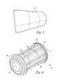
- FIG. 3is a perspective view of another embodiment of an SMP apparatus in a rigid, inflated state
- FIG. 4is a perspective view of an inner mandrel tool constructed in accordance with an embodiment of the present invention.
- FIG. 5is an exploded perspective view of the SMP apparatus of FIG. 3 after it is slid over the inner mandrel tool illustrated in FIG. 4 and is heated to contract against the inner mandrel tool, and also illustrates end seals configured to seal the SMP apparatus to the inner mandrel tool at each end thereof;
- FIG. 6 ais a perspective view of internal stiffeners constructed according to embodiments of the present invention and configured to be co-bonded or co-cured to a composite part;
- FIG. 6 bis a fragmentary perspective view of a dummy skin and dummy stiffeners constructed in accordance with an embodiment of the present invention to assist in forming the SMP apparatus of FIG. 5 into a desired rigid tool configuration;
- FIG. 7is a fragmentary perspective view of the dummy skin and dummy stiffeners of FIG. 6 , further illustrating reinforcement inserts placed over and onto the dummy stiffeners;
- FIG. 8is an exploded perspective view of the inner mandrel tool of FIG. 5 placed into a rigid external tool constructed in accordance with an embodiment of the present invention
- FIG. 9is a perspective view of the SMP apparatus of FIG. 5 in the desired rigid tool configuration with the dummy internal stiffeners resting in cavities formed therein;
- FIG. 10 ais a perspective view of the SMP apparatus of FIG. 9 in the desired rigid tool configuration with the internal stiffeners removed from the cavities formed therein;
- FIG. 10 bis a perspective view of the SMP apparatus of FIG. 5 in the desired rigid tool configuration with the internal stiffeners of FIG. 6 a resting in the cavities formed therein;
- FIG. 11is a perspective view of the SMP apparatus of FIG. 9 with composite material applied thereon and around the internal stiffeners;
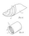
- FIG. 12is a fragmentary perspective view of the SMP apparatus and the composite material of FIG. 11 after the composite material is cured, illustrating space between the SMP apparatus and the cured composite material once the SMP apparatus is heated and contracted back toward the inner mandrel tool;
- FIG. 13is a perspective view of the composite material of FIG. 12 and the internal stiffeners of FIG. 6 co-cured or co-bonded together into a rigid fuselage, with the inner mandrel tool, the rigid external tool, and the SMP apparatus removed therefrom;
- FIG. 14is a flow chart of a method for forming the SMP apparatus into a desired rigid tool configuration in accordance with an embodiment of the present invention
- FIG. 15is a flow chart of a method for fabricating a fuselage using the SMP apparatus in accordance with an embodiment of the present invention.
- FIG. 16is a fragmentary cross-sectional view of a J-stringer being formed between two SMP apparatuses and a rigid molding tool, each constructed in accordance with an embodiment of the present invention.
- FIG. 17is a flow chart of a method for fabricating a composite stiffener using the SMP apparatus in accordance with an embodiment of the present invention.
- references to “one embodiment”, “an embodiment”, or “embodiments”mean that the feature or features being referred to are included in at least one embodiment of the technology.
- references to “one embodiment”, “an embodiment”, or “embodiments” in this descriptiondo not necessarily refer to the same embodiment and are also not mutually exclusive unless so stated and/or except as will be readily apparent to those skilled in the art from the description.
- a feature, structure, act, etc. described in one embodimentmay also be included in other embodiments, but is not necessarily included.
- the present technologycan include a variety of combinations and/or integrations of the embodiments described herein.
- One embodiment of the present inventionis a method for making composite parts.
- This embodiment of the inventionmay be implemented with a shape memory polymer (SMP) apparatus 12 , as best shown in FIGS. 1-2 , and/or a rigid external tool 28 , as later described herein and illustrated in FIG. 2 .
- the SMP apparatus 12may be used as both a mandrel or rigid tooling for applying composite material 14 thereon, as illustrated in FIG. 1 , and a bladder for providing outward pressure to the composite material 14 during a cure of the composite material 14 into a hardened composite part, as illustrated in FIG. 2 .
- the SMP apparatus 12may be formed of SMP material cast into any memory shape.
- the SMP apparatus 12may be cast into an elongated and/or hollow configuration having one or more open ends using any method known in the art, such as methods of forming an SMP cylinder disclosed in U.S. Pat. No. 7,422,714, incorporated by reference herein in its entirety.
- the SMP apparatus 12may be a pre-formed SMP cylinder or barrel open at two opposing ends.
- the SMP apparatus 12may have any cross-sectional shape, such as a trapezoid, rectangle, square, or triangle, or may be cast into a non-hollow configuration.
- the cast shape of the SMP apparatusis referred to herein as its memory shape.
- the SMP material used to form the SMP apparatus 12may be reinforced or unreinforced SMP material.
- the SMP material used to form the SMP apparatus 12may be an epoxy, an epoxy-based SMP, a styrene copolymer based SMP or any other type or combination of SMPs, such as cyanate ester, polyurethane, polyethylene homopolymer, styrene-butadiene, polyisoprene, copolymers of stearyl acrylate and acrylic acid or methyl acrylate, norbonene or dimethaneoctahydronapthalene homopolymers or copolymers, and malemide.
- the SMP material used in the SMP apparatus 12may be any of the SMPs described in U.S. Pat. Nos. 7,422,714, 6,986,855, 7,276,195, U.S. Patent Application Publication Nos. 2008/0021188, 2008/0021166, and/or 2008/0269420, all of which are incorporated herein in their entireties by reference.
- numerous other types of SMPsexist and can be tailored to meet specific tolerances and temperature requirements.
- the modulus of various SMP materialscan be changed through several different methods, such as a temperature change, an electric current, water, and/or light.
- a temperature changesuch as a temperature change, an electric current, water, and/or light.
- the exemplary methods described hereindisclose the use of temperature changes to transform the SMP apparatus 12 from a malleable state to a rigid state and vice versa.
- any of the above-listed triggers for changing the modulus of the SMP material of the SMP apparatus 12may be used for the composite part fabrication methods described herein without departing from the scope of the invention.
- a glass transition temperature (T g ) of an SMP materialis defined herein as a threshold temperature at and/or above which that SMP material begins to transition to a lower modulus state, becoming soft and/or malleable in order to be deformed. Therefore, the SMP apparatus 12 of the present invention may be configured to begin to become flexible and formable when it is heated above its T g and to become rigid when cooled to a temperature below its T g . If the SMP apparatus 12 is deformed at a temperature above T g and then held in that deformed state as its temperature drops below T g , then the SMP apparatus 12 hardens in that deformed state. When heated again, the SMP apparatus 12 may generally return to its originally-cast memory shape unless otherwise acted on by another force. While the modulus change of the SMP apparatus 12 may begin at T g , there may be a range of transition temperatures through which the SMP apparatus 12 may become increasingly malleable.
- the SMP apparatus 12may be made of an SMP material having any T g appropriate for the uses and methods described herein.
- T gmay be equal to or less than the curing temperature for the composite material 14 , such that the SMP apparatus 12 may be used as an expandable bladder during curing of the composite part.
- T gmay be greater than the curing temperature for the composite material 14 such that the SMP apparatus 12 remains rigid during cure of the composite part.
- T gmay be a temperature between 100° F. and 700° F.
- T gmay be a temperature between 100° F. and 200° F., 200° F. and 300° F., or between 300° F. and 400° F.
- T gmay be a temperature between 125° F. and 175° F., 250° F. and 300° F., or 350° F. and 400° F.
- T g of the SMP apparatus 12may be approximately equal to 143° F., 275° F., or 375° F.
- the SMP apparatus 12may become increasingly malleable when heated through a transition range of temperatures beginning at or centered around T g and may gradually harden to its rigid state when cooled through the transition range of temperatures to a temperature at or below T g .
- the rigid external tool 28may have any shape or configuration desired for fabricating the composite part.
- the rigid external tool 28may have a hollow space into which the SMP apparatus 12 and the composite material 14 may be placed.
- the rigid external tool 28may be a barrel tool or a clamshell tool.
- the rigid external tool 28as illustrated in FIG. 2 , may form an outer surface of the composite part.
- the rigid external tool 28may be replaced with any type of mold shaped and configured for forming an inner or outer surface of a composite part.
- the rigid external tool 28may also be used to help shape or form the SMP apparatus 12 .
- dummy skin 22 , dummy internal stiffeners 23 , and/or reinforcement inserts 26may be placed in or attached to the rigid external tool 28 , as described in detail below, to provide a desired mold configuration for the SMP apparatus 12 .
- the composite material 14 placed on the SMP apparatus 12 to form the composite partmay comprise or be in the form of low temperature resin, high temperature resin, toughened resin, prepreg, wet processed fiber, dry fiber, continuous fiber, discontinuous fiber, chopped fiber, glass, KEVLAR, carbon, and/or core.
- Coreis defined herein as any offset component separating two layers of composite material.
- coremay comprise foam, thermoplastic, honeycomb materials, aluminum, fiberglass phenolic, carbon, Nomex, etc. Core may also be referred to as core panels, honeycomb core, or sandwich panel core.
- chemical makeup of the composite material 14may include epoxy, BMI, benzoxazine, vinyl, acrylic, polyester, polyamide, phthalonitrile, and any other similar substances known in the art.
- the composite material 14may be placed onto the SMP apparatus 12 using automated fabric placement, automated fiber placement, automated filament winding, fabric placement, hand lay-up, or any other method known in the art.
- the composite material 14may be configured to be hardened or cured, such as in an autoclave, out of an autoclave, via a low-temperature cure process, and/or via a high-temperature cure process.
- the SMP apparatus 12may be formed into a rigid tool configuration and then the composite material 14 may be applied thereon.
- the SMP apparatus 12may be shaped by one or more inner molds placed inside the SMP apparatus 12 and/or one or more outer molds (such as the rigid external tool 28 ) placed outside of the SMP apparatus 12 .
- the inner or outer moldsmay comprise any number of components integrally formed or assembled together to provide a desired shape to the SMP apparatus 12 , such as the dummy skin 22 , dummy internal stiffeners 23 , and/or reinforcement inserts 26 placed into or onto the rigid external tool 28 in any desired configuration.
- any method of forming the SMP apparatus 12may be used without departing from the scope of the invention.
- the SMP apparatus 12may be sealed to the inner or outer molds, heated, and then pressed against the inner or outer molds.
- the SMP apparatus 12may be pressed against the molds by way of a pressure differential induced via inflation, vacuum, and/or any other method known in the art for urging the SMP apparatus 12 toward the mold.
- the SMP apparatus 12may be heated and inflated toward the outer mold into a configuration for forming an inner surface of a composite part.
- the SMP apparatus 12may be removed from the inner or outer molds and composite material 14 may be placed onto the SMP apparatus 12 using any method known in the art, such as fiber placement.
- the SMP apparatus 12may be referred to herein as being in the “rigid tool configuration” after it is formed into the desired shape for the composite material 14 to be applied thereto.
- cavities 40may be formed into the SMP apparatus 12 so that components (such as internal stiffeners like composite frames, stringers, or cores) may be placed into the cavities to be co-bonded or co-cured to the composite material 14 . Then the composite material 14 may be placed over and/or onto both the SMP apparatus 12 and the components to be co-bonded or co-cured thereto. These cavities 40 may hold components to be co-bonded or co-cured to the composite material 14 in place during application of the composite material 14 without the need for any mechanical attachments. Additionally or alternatively, various restraints may be used to keep the internal stiffeners in place during application of the composite material 14 . Then pressure via the SMP apparatus 12 may compress these components or internal stiffeners against the composite material during cure, thus co-curing or co-bonding them together.
- componentssuch as internal stiffeners like composite frames, stringers, or cores
- the size and shape of the SMP apparatus 12may be configured to allow thicker composite material 14 or additional layers of composite material 14 to be applied thereon at select locations.
- the SMP apparatus 12may have a portion with a smaller cross-sectional area and a portion with a larger cross-sectional area. The portion of the SMP apparatus 12 with the smaller cross-sectional area may allow for a greater amount of composite material 14 to be applied thereon.
- the SMP apparatus 12may be shaped and configured to provide enough clearance or offset between the SMP apparatus 12 and the rigid external tool 28 so that a desired thickness of composite material 14 and/or the internal stiffeners can fit within said offset.
- the SMP apparatus 12 and the composite material 14may have heat and pressure applied thereto in order to cure the composite material 14 and/or to co-cure or co-bond other components or internal stiffeners to the composite material 14 . Additionally, the heat may also be used to change the modulus of the SMP apparatus 12 .
- the SMP apparatus 12 and the composite material 14may be placed in the hollow space of the rigid external tool 28 and heated and pressurized as required for curing the composite material 14 .
- the heat used during this curing processmay be greater than T g of the SMP apparatus 12 , causing the SMP apparatus 12 to convert to its malleable state, and a pressure differential applied from within and/or without the SMP apparatus 12 (e.g., via autoclave) may cause the SMP apparatus 12 to be urged toward the rigid external tool 28 .
- the heatmay transform the SMP apparatus 12 from the rigid tool configuration into a bladder configuration in which the SMP apparatus 12 becomes flexible and inflatable, acting as an internal bladder to compress the composite material 12 against the rigid external tool 28 , as illustrated in FIG. 2 .
- a small pressure differential or pressurizationmay be applied to the SMP apparatus 12 until its temperature exceeds T g , at which point the pressure may be stepped up to the full amount of desired pressure.
- the SMP apparatus 12may therefore be used to press the composite material 14 against the rigid external tool 28 or any alternative rigid mold surface.
- the pressure differentialas described herein, can be induced using a variety of methods, with the SMP apparatus 12 sealed in an air-tight manner to one of the rigid tools or molds described herein, such that the SMP apparatus 12 inflates toward the composite material and/or is drawn against the composite material 14 during cure.
- the pressure differentialis introduced via autoclave.
- a vacuum bag or other impermeable sheet of materialmay be applied in such a manner to urge the SMP apparatus 12 , in its malleable state, toward a rigid surface to compress the composite material 14 between the SMP apparatus 12 and the rigid surface.
- the vacuum bag or other impermeable sheet of materialmay be sealed to one of the rigid tools or molds described herein, such as the rigid external tool 28 .
- the SMP apparatus 12is not impermeable, comprises any holes or tears therein, and/or can not be sealed to another surface such that a pressure differential may be induced between the SMP apparatus 12 and the surface to which it is sealed.
- the vacuum bagmay be sealed to the rigid external tool 28 and may be used to drive the SMP apparatus 12 , in its malleable state, in a desired direction by way of a pressure differential applied to the vacuum bag.
- the SMP apparatus 12may be configured to experience a change in modulus in response to triggers other than heat, such as an electric current, water, and/or light. Therefore, in some embodiments of the invention, one of the other triggers may also be applied to the SMP apparatus 12 as the composite material 14 is being cured, so that the SMP apparatus 12 is malleable enough to inflate or otherwise compress the composite material 14 against the rigid external tool 28 .
- the pressure differentialmay be substantially equalized while the temperature is maintained above T g , and then the SMP apparatus 12 in the flexible bladder configuration may be removed from within the cured composite part.
- a pressure differential sufficient to urge the SMP apparatus 12 away from the cured composite materialmay be induced.
- the SMP apparatus 12may contract back to its original or memory shape, allowing for easy removal of the SMP apparatus 12 from within the resulting composite part.
- an internal mandrel placed within the SMP apparatus 12may be configured to draw the SMP apparatus 12 (still in its malleable state) away from the composite part.
- the SMP apparatus 12may be urged away from the cured composite part while still in the malleable state, then allowed to cool and/or become at least somewhat rigid or fully rigid again before being removed from within the cured composite part.
- the SMP apparatus 12may be used to form a variety of composite parts of varying geometries, such as composite parts with trapped geometries.
- the composite partsmay be aircraft fuselages, wings, nacelles, panels, ducts, and aircraft structural supports or stiffeners.
- aircraft structural supportsmay include stringers, frames, trapezoidal hat-shaped stiffeners, bell-shaped stiffeners, inverted hat stiffeners, J-stiffeners, F-stiffeners, blade stiffeners, I-stiffeners, and C-stiffeners.
- the composite parts formed with the SMP apparatus 12may include rotorcraft, pylons, thrust reversers, shrouds, inlets, winglets, wing tips, vertical and horizontal stabilizers, airframe structures, empennage, spars, ribs, tubular airframe structures, control surfaces, nose sections, fairings, flaps, ailerons, spoiler, slats, torque tubes, drive shafts, cowls, engine inlets, exhaust nozzles, exhaust cones, propellers, gearboxes, transmission housings, cuffs, rotor blades, fuel tanks, landing gear, landing gear wells, doors, subframes, longerons, wire trays, struts, brackets, frame stabilizers, gunmounts, control pedestals, instrument consoles, etc.
- These composite partsmay be formed using the SMP apparatus 12 by first placing the composite material 14 against at least a portion of the SMP apparatus 12 when the SMP apparatus 12 is in its rigid tool configuration. Then the composite material 14 may be compressed against and/or by the SMP apparatus 12 in a rigid or malleable state during curing of the composite material 14 into the composite part. In some embodiments of the invention, more than one SMP apparatus 12 may be used to fabricate the composite part, as later described herein. In some embodiments of the invention where a plurality of SMP apparatuses are used to form the composite part, the SMP apparatuses may be configured to have different T g temperatures or different triggers for changing the modulus of the different SMP apparatuses, as described above.
- internal stiffenersmay be co-cured or co-bonded with any composite part, such as the composite parts listed above, using the SMP apparatus 12 , as later described herein.
- co-curingis defined herein as simultaneously curing and bonding two uncured composite parts.
- co-bondingis defined herein as simultaneously curing one uncured composite part while bonding the uncured composite part to a hardened part or a previously-cured composite part.
- Internal stiffenersmay include, for example, frames, stringers, or core, as defined above.
- the frames and stringersmay be elongated structural stiffeners extending laterally and/or perpendicular relative to a length a composite part. In some embodiments of the invention, the frames may cross the stringers in a grid-like configuration.
- Examples of some specific types of frames and stringersmay include trapezoidal hat-shaped stiffeners, bell-shaped stiffeners, inverted hat stiffeners, J-stiffeners, F-stiffeners, blade stiffeners, I-stiffeners, and C-stiffeners.
- the SMP apparatus 12may be used to form a variety of other composite parts, such as trailers, automotive ducts and manifolds, hoses, tires, turbochargers, tanks, automobiles, racing vehicles, boats, yachts, bicycles, canoes, kayaks, paddles, sporting goods, gun stocks, grips, crossbows and accessories, golf clubs and related components, fishing rods, guitars, pipes, poles, building supplies, wind turbine blades, engine components, furniture, sail masts, electronic enclosures, armor, driveshafts, satellites, missiles, and spacecraft.
- composite partsmay be formed using methods similar to any of the methods described herein.
- Another embodiment of the present inventionis a method of fabricating an aircraft fuselage 15 with integrated internal stiffeners 24 , as illustrated in FIG. 13 .
- the method of this embodimentmay be implemented with the SMP apparatus 12 , as described above, along with an inner mandrel tool 16 , end seals 18 , 20 , the dummy skin 22 , the internal stiffeners 24 , the reinforcement inserts 26 , and the rigid external tool 28 , as best illustrated in FIGS. 2-12 .
- the SMP apparatus 12may have the traits and characteristics described above in reference to the embodiment of the invention illustrated in FIGS. 1-2 .
- the SMP apparatus 12may have a barrel, bottle, funnel, cone, or cylinder shape as its cast memory shape.
- any other cast memory shapemay be used without departing from the scope of the invention.
- the SMP apparatus 12may be received in an inflated state. Specifically, the SMP apparatus 12 may have been previously heated and inflated to a larger diameter than that of its memory shape and then cooled and hardened in that inflated state.
- the SMP apparatus 12may comprise one or two open ends.
- the SMP apparatus 12may be approximately 1 inch to 35 ft in diameter and approximately 1 ft to 75 ft in length. However, the SMP apparatus 12 may have any dimensions without departing from the scope of the invention.
- the inner mandrel tool 16may be made of any rigid, durable material which remains rigid throughout a composite cure cycle.
- the inner mandrel tool 16may be substantially cylindrical.
- the inner mandrel tool 16may be hollow, having a cylindrical wall 30 and two opposing ends 32 , 34 that may comprise openings (not shown) to the hollow space within the inner mandrel tool 16 .
- one or more inflation openings 36may be provided through the cylindrical wall 30 such that a compressed gas may be forced within the hollow inner mandrel tool 16 , such as by way of airlines (not shown), thereby providing inflation force outward from the inner mandrel tool 16 .
- the inflation openings 36may also be configured for suctioning the SMP apparatus 12 against the inner mandrel tool 16 during various steps of fabricating the fuselage 15 , as described below.
- an outer surface of the inner mandrel tool 16may also comprise varying contours.
- the varying contoursmay include a number of protrusions 38 and/or indentions for use in recovery of the SMP apparatus 12 after cure of the composite part.
- an outer surface of the cylindrical wall 30may comprise the protrusions 38 in the form of a plurality of ridges or ribs circumferentially or axially spaced and arranged substantially parallel with each other.
- Each of the ridges or ribsmay extend between the opposing ends 32 , 34 of the inner mandrel tool 16 and may be shaped with a wavy or sinusoidal pattern extending between the opposing ends 32 , 34 of the inner mandrel tool 16 , as illustrated in FIG. 4 .
- the protrusions 38may be one or more concentric rings formed around the inner mandrel tool 16 , or may have any other configuration.
- the protrusions 38may be integrally formed or otherwise attached to the inner mandrel tool 16 .
- the purpose of the varying contours or protrusions 38may be to introduce a greater amount of strain to the SMP apparatus 12 in a smaller cross-sectional area. Specifically, when the SMP apparatus 12 is urged by an induced pressure differential toward the inner mandrel tool 16 to be removed from within a cured composite part, the varying contours or protrusions 38 prevent the SMP apparatus 12 from folding over onto its self. For example, after its outward expansion during cure, as later described herein, the SMP apparatus 12 may be stretched out. The axial and/or hoop strain induced by the varying contours or protrusions 38 may prevent the SMP apparatus 12 from folding over on itself or creasing and damaging the SMP material.
- the varying contours, protrusions 38 , and/or indentionsprovide a larger surface area for the SMP apparatus 12 to contact against without requiring an increase in size and/or cross-section of the inner mandrel tool 16 .
- the radius of the inner mandrel tool 16is “r”, and the length is “L”, then the equation for the surface area would normally be 2 ⁇ *r*L.
- the surface area of the inner mandrel tool 16 in FIG. 4is greater than 2 ⁇ *r*L.
- the end seals 18 , 20may be any end fittings, seals, and/or sealant configured for providing an airtight seal between the SMP apparatus 12 and the inner mandrel tool 16 at or proximate to the ends 32 , 34 of the SMP apparatus 12 .
- the end seals 18 , 20may be swage locks shaped and configured to attach to the ends 32 , 34 of the inner mandrel tool 16 over portions of the SMP apparatus 12 proximate to the open ends of the SMP apparatus 12 , thereby forming a pressure vessel within the SMP apparatus 12 .
- the end seals 18 , 20may be substantially circular swage locks. Inflation pressure may be introduced by pumping compressed gas into the SMP apparatus 12 by way of one or more airlines (not shown) fed through the end seals 18 , 20 in some embodiments of the invention. However, pressure applied to the SMP apparatus 12 may be provided through any openings in the end seals 18 , 20 , the inner mandrel tool 16 , and/or the rigid external tool 28 without departing from the scope of the invention. Note that in some embodiments of the invention, the end seals 18 , 20 may be omitted or may rather be configured to additionally or alternatively seal the SMP apparatus 12 to the rigid external tool 28 .
- the dummy skin 22may be made from any material and may have a thickness corresponding to a thickness of the uncured composite material 14 to be placed onto the SMP apparatus 12 .
- the dummy skin 22may be made of composite material forms, metal, unreinforced plastics, or any material exhibiting good dimensional stability under heat and pressure.
- the dummy skin 22may be formed of composite material, such as graphite fiber reinforced epoxy composite laminate.
- the dummy skin 22is configured to be placed within the rigid external tool 28 , as later described herein, during deformation of the SMP apparatus 12 into the rigid tool configuration.
- the dummy skin 22may also include or be integrally formed with the dummy internal stiffeners 23 .
- the dummy internal stiffeners 23may be rigid structures sized and shaped substantially identical to the internal stiffeners 24 and arranged on the dummy skin 22 to represent the cured or uncured internal stiffeners 24 during deformation of the SMP apparatus into the rigid tool configuration.
- the dummy internal stiffeners 23may alternatively, be sized and shaped to represent both the internal stiffeners and the reinforcement inserts 26 during deformation of the SMP apparatus 12 into the rigid tool configuration.
- the internal stiffeners 24may be any sub-structure stiffeners configured to be co-bonded and/or co-cured to the composite material 14 of the fuselage or other composite part.
- the internal stiffeners 24may be elongated structural components curved to match a contour of an internal surface of the fuselage.
- the internal stiffeners 24may comprise cured composite material or uncured composite material in the form of internal frame pieces, such as frames and stringers.
- the internal stiffeners 24may be held in a desired shaped during cure via the reinforcement inserts 26 , as later described herein.
- internal stiffeners 24include, but are not limited to trapezoidal hat-shaped stiffeners, bell-shaped stiffeners, inverted hat stiffeners, J-stiffeners, F-stiffeners, blade stiffeners, I-stiffeners, C-stiffeners, core stiffeners, sandwich panel core, honeycomb core, and the like.
- the internal stiffeners 24may include approximately 8-inch tall frames & approximately 3-inch tall stringers. However, any dimensions may be used without departing from the scope of this invention.
- the framesmay be configured to intersect with the stringers in a grid-like configuration within the finished fuselage 15 .
- the stringersmay be formed to overlap the frames and/or the frames may be formed to overlap the stringers, as illustrated in FIG. 6 a .
- the overlapping of the internal stiffeners 24may be accomplished by sizing and shaping the internal stiffeners 24 to fit together like puzzle pieces.
- the same configurationsmay also be used for the dummy internal stiffeners 23 , as illustrated in FIGS. 6 b , 7 , 8 , and 9 .
- the reinforcement inserts 26may be made of a rigid material, such as a nickel steel alloy like INVAR, and may contact and/or mate with portions of the internal stiffeners 24 and/or the dummy internal stiffeners 23 facing the SMP apparatus 12 .
- the reinforcement inserts 26may be configured to alleviate sharp corners and bends of the internal stiffeners 24 and/or the dummy internal stiffeners 23 to better facilitate forming the SMP apparatus 12 .
- the reinforcement inserts 26may be configured to mate with or rest within one or more angles presented by one or more of the internal stiffeners 24 and/or dummy internal stiffeners 23 .
- one of the reinforcement inserts 26may have two surfaces meeting at a right angle and configured to mate with the right angle of that internal stiffener 24 or dummy internal stiffener 23 .
- the reinforcement inserts 26may also have surfaces facing away from the internal stiffener 24 or dummy internal stiffener 23 that are substantially flat and/or present more gradual angles.
- one or more of the reinforcement inserts 24may have at least one chamfered or angled surface and/or rounded edges which may contact the SMP apparatus 12 as it is urged outward toward the rigid external tool 28 , as later described herein.
- the reinforcement inserts 26may also be curved, length-wise, to substantially match a curve of the internal stiffeners 24 , the dummy internal stiffeners 23 , and/or the inner surface of the rigid external tool 28 .
- the internal stiffeners 24 and/or the dummy internal stiffeners 23 , along with the reinforcement inserts 26may be configured to form cavities 40 , such as grooves or channels, into the SMP apparatus 12 , as illustrated in FIG. 10 and later described herein.
- the dummy internal stiffeners 23 and/or the reinforcement inserts 26may be configured to form the cavities 40 into the SMP apparatus 12 , and may later be replaced with the internal stiffeners 24 .
- the dummy skin 22 , dummy internal stiffeners 23 , and/or reinforcement inserts 26may be removed from the cavities 40 and replaced with the uncured internal stiffeners 24 , configured against the reinforcement inserts 26 , to be co-cured within the fuselage 15 .
- the dummy skin 22 , dummy internal stiffeners 23 , and/or reinforcement inserts 26may be removed from the cavities 40 and replaced with pre-cured internal stiffeners 24 , configured against the reinforcement inserts 26 to be co-bonded with the fuselage 15 .
- the internal stiffeners 24 and/or the dummy internal stiffeners 23may comprise J-stiffeners 42 supported on at least two sides by corresponding reinforcement inserts 26 .
- the internal stiffeners 24 and/or the dummy internal stiffeners 23 in this example embodimentmay comprise frames 44 having a substantially “T”-shaped cross-section, with the frames 44 also each supported on at least two sides by corresponding reinforcement inserts 26 .
- the reinforcement inserts 26 and/or portions of the dummy internal stiffeners 23may be held in place and held together by mechanical fasteners 46 , such as splice straps and bolts.
- the internal stiffeners 24 and/or the dummy internal stiffeners 23may have any known configurations and the reinforcement inserts 26 may be of any shape and configuration to mate therewith.
- the rigid external tool 28may be a rigid tool having an inner surface configured to form a shape of an outer surface of the fuselage 15 .
- the rigid external tool 28may be a clamshell tool, as illustrated in FIG. 2 or as illustrated in FIG. 8 , and may have two halves, including a lower clamshell and an upper clamshell. Together, the two halves may form a hollow cylindrical shape bounded by the inner surface of the rigid external tool 28 .
- the rigid external tool 28may comprise any plurality of portions which, when joined together, may form an inner surface configured for forming the shape of the outer surface of the fuselage 15 .
- a method of fabricating the fuselage 15may include the steps of forming the SMP apparatus 12 into the rigid tool configuration with the cavities 40 for the internal stiffeners 24 , placing the cured or uncured internal stiffeners 24 and reinforcement inserts 26 into the cavities 40 in the SMP apparatus 12 , placing the uncured composite material 14 onto the SMP apparatus 12 , then placing that SMP apparatus 12 and the uncured composite material 14 into the rigid external tool 28 .
- the methodmay next include the steps of curing the composite material 14 via pressure and heat while simultaneously inflating or otherwise expanding the SMP apparatus 12 to compress the composite material 14 against the rigid external tool 28 during the curing process, then, once the composite material 14 is cured, urging the SMP apparatus 12 to a reduced cross-section, and extracting the SMP apparatus 12 out from within the resulting fuselage.
- the internal stiffeners 24are thereby co-bonded and/or co-cured with the composite fuselage, eliminating the need for mechanical fasteners to attach the internal stiffeners 24 to the fuselage.
- the flow chart of FIG. 14depicts the steps of an exemplary method 1400 for forming the SMP apparatus 12 into the rigid tool configuration used to fabricate the fuselage 15 .
- the functions noted in the various blocksmay occur out of the order depicted in FIG. 14 .
- two blocks shown in succession in FIG. 14may in fact be executed substantially concurrently, or the blocks may sometimes be executed in the reverse order depending upon the functionality involved.
- the method 1400may comprise the steps of receiving the SMP apparatus 12 in the inflated state, as illustrated in FIG. 3 , or receiving the SMP apparatus 12 in its memory shape and then heating and inflating the SMP apparatus 12 into its inflated state, as depicted in block 1402 .
- This expansion of the SMP apparatus 12may also be accomplished using various other triggers to change the modulus of the SMP apparatus 12 and/or various other forces or techniques to expand the SMP apparatus 12 to the desired size.
- the SMP apparatus 12may then be large enough to be slid over the inner mandrel tool 16 .
- the SMP apparatus 12may be cast with a memory shape large enough to fit over the inner mandrel tool 16 .
- the next step of method 1400may be sliding the inner mandrel tool 16 into the SMP apparatus 12 or sliding the SMP apparatus 12 onto the inner mandrel tool 16 , as depicted in block 1404 .
- the SMP apparatus 12may be received in a collapsed state and may already be conformed to the inner mandrel tool 16 of FIG. 4 .
- the method 1400may comprise heating the SMP apparatus 12 above T g at which the SMP material becomes malleable and formable, as depicted in block 1406 .
- T g threshold temperatureAbove the T g threshold temperature, the SMP apparatus 12 may naturally contract back toward its original memory shape and size, causing the SMP apparatus 12 to contract around and form to the inner mandrel tool 16 , as illustrated in FIG. 5 .
- vacuummay be applied from within the inner mandrel tool 16 , via the inflation openings, and may suction the heated, malleable SMP apparatus 12 against the inner mandrel tool 16 .
- the inner mandrel tool 16may have chamfered or angled portions 48 at each of the opposing ends 32 , 34 to which the SMP apparatus 12 may be conformed. Any excess material extending outward beyond the chamfered or angled portions 48 may need to be darted or cut off.
- the method 1400may further comprise the step of applying the end seals 18 , 20 to the SMP apparatus 12 and the inner mandrel tool 16 , as depicted in block 1408 , creating a pressure vessel between the inner mandrel tool 16 and the SMP apparatus 12 .
- end portions of the SMP apparatus 12may be pressed inward toward the inner mandrel tool 16 and/or its chamfered or angled portions 48 and locked thereto by the end seals 18 , 20 , such as swage locks.
- the end seals 18 , 20may mate with the chamfered or angled portions 48 of the inner mandrel tool 16 , sandwiching portions of the SMP apparatus 12 between the end seals 18 , 20 and the inner mandrel tool 16 to form an airtight seal.
- the step of applying the end seals 18 , 20may be omitted or the SMP apparatus 12 may be sealed in other ways or to other surfaces to allow a pressure differential to act on the SMP apparatus 12 .
- the next step of method 1400may comprise placing the dummy internal stiffeners 23 and/or reinforcement inserts 26 onto the dummy skin 22 in a configuration corresponding with desired locations of the internal stiffeners 24 within the fuselage, as depicted in block 1410 and illustrated in FIG. 7 .
- the dummy skin 22 , dummy internal stiffeners 23 , and/or the reinforcement inserts 26may be covered with a thin film or some other substance to prevent them from sticking to each other and/or to the SMP apparatus 12 .
- the method 1400may then comprise placing the dummy skin 22 into the rigid external tool 28 , as depicted in block 1412 .
- the dummy skin 22may be applied to the inner surface of the rigid external tool 28 in order to mimic or serve as a place holder for the thickness of the composite material 14 which will later be placed onto the SMP apparatus 12 . This ensures that the SMP apparatus 12 with the composite material 14 applied thereon at a desired thickness will still fit within the rigid external tool 28 .
- the reinforcement inserts 26may be positioned onto the dummy skin 22 resting on the rigid external tool 28 along with the dummy internal stiffeners 23 , which may be shaped and configured to emulate the size and configuration of the cured or uncured internal stiffeners 24 .
- the dummy internal stiffeners 23may later be removed from the cavities 40 and replaced with the cured or uncured internal stiffeners 24 .
- the cured or uncured internal stiffeners 24 along with the reinforcement inserts 26may then be placed into the grooves or cavities 40 to co-bond or co-cure the internal stiffeners 24 with the composite material 14 fabricating the fuselage 15 .
- the dummy internal stiffeners 23may be omitted and/or replaced with the internal stiffeners 24 in any of the steps described herein in an uncured or cured state.
- the internal stiffeners 24 and/or the reinforcement insertsmay be used to form the cavities 40 .
- the internal stiffeners 24may be pre-cured and/or cured during shaping of the SMP apparatus 12 and may later be co-bonded to the composite material 14 during its cure, thus fabricating the fuselage 15 .
- the method 1400may further comprise the steps of placing the SMP apparatus 12 , along with the inner mandrel tool 16 , inside the rigid external tool 28 , as depicted in block 1414 and illustrated in FIG. 8 , and then heating and pressurizing the SMP apparatus 12 , as depicted in block 1416 .
- the heat and pressuremay force the SMP apparatus 12 to inflate and press against the dummy skin 22 , dummy internal stiffeners 23 , internal stiffeners 24 , and/or reinforcement inserts 26 .
- the SMP apparatus 12may be heated to or above T g in order to change the modulus of the SMP apparatus 12 to make it formable and expandable.
- method steps 1410 - 1414may be replaced with a step of placing the SMP apparatus 12 inside any rigid outer mold shaped and configured to mimic an inner surface of the composite part being formed and comprising protrusions for forming the desired cavities 40 into the SMP apparatus 12 .
- the pressure or pressure differentialmay be induced in a number of ways, such as via a forced compressed gas applied through the inflation openings 36 of the inner mandrel tool 16 , as illustrated in FIG. 4 .
- the pressure required to expand the SMP apparatus 12may depend on the thickness and/or overall size of the SMP apparatus 12 .
- the type of SMP material used and/or the design of the SMP apparatus 12may also affect how easy or how difficult it is to strain the SMP apparatus 12 .
- pressure in a range of 1-150 pound-force per square inch gauge (psig) or pressure in a narrower range of 30-90 psigmay be applied to inflate the SMP apparatus 12 .
- approximately 45 psigmay be applied within the SMP apparatus 12 to inflate the SMP apparatus 12 .
- a low pressure differentialmay be induced as heat is ramped up to or above T g to prevent the SMP apparatus 12 from collapsing away from the composite material 14 as it starts to soften. Then, at some point after the SMP apparatus 12 exceeds T g , the pressure differential may be stepped up to the full desired amount.
- a low pressure of approximately 5 to 10 psimay be applied within the SMP apparatus 12 until enough heat has been applied to make the SMP apparatus 12 sufficiently malleable, at which point the pressure applied therein may be stepped up to the cure cycle pressure, such as 30-90 psi.
- the method 1400may comprise cooling the SMP apparatus 12 to harden it in the rigid tool configuration, as depicted in block 1418 .
- the inflation pressuremay continue to be applied as the temperature of the SMP apparatus 12 is cooled to a point below T g such that the SMP apparatus is hardened in its inflated rigid tool configuration.
- the SMP apparatus 12is thereby shaped according to the dummy skin 22 , dummy internal stiffeners 23 , internal stiffeners 24 , and/or reinforcement inserts 26 , which form the cavities 40 , cavities, or grooves into the SMP apparatus 12 .
- the method 1400may then comprise removing the SMP apparatus 12 and inner mandrel tool 16 from the rigid external tool 28 .
- the dummy skin 22may also be removed from the SMP apparatus 12 , as illustrated in FIG. 9 .
- FIG. 10 afurther illustrates the resulting SMP apparatus 12 in the rigid tool configuration after the dummy internal stiffeners 23 are removed, thereby revealing the cavities 40 formed by method 1400 .
- FIG. 10 billustrates the resulting SMP apparatus 12 in the rigid tool configuration with the internal stiffeners 24 placed where the dummy internal stiffeners 23 were located in FIG. 9 .
- the flow chart of FIG. 15depicts the steps of an exemplary method 1500 for fabricating the fuselage 15 using the SMP apparatus 12 in more detail.
- the functions noted in the various blocksmay occur out of the order depicted in FIG. 15 .
- two blocks shown in succession in FIG. 15may in fact be executed substantially concurrently, or the blocks may sometimes be executed in the reverse order depending upon the functionality involved.
- the method 1500may first include the step of forming the SMP apparatus 12 into the rigid tool configuration, as depicted in block 1502 and in the method steps of FIG. 14 . As noted above, this step may require forming the cavities 40 in the SMP apparatus 12 in a configuration corresponding with desired locations of the internal stiffeners 24 within the finished fuselage 15 . A variety of methods may be used to shape the SMP apparatus 12 into the desired rigid tool configuration with the cavities 40 , cavities, or grooves formed therein.
- the method 1500 of fabricating the fuselage 15may include the step of placing the cured or uncured internal stiffeners 24 and reinforcement inserts 26 into the cavities in the SMP apparatus 12 , as depicted in block 1504 and illustrated in FIG. 10 b .
- the internal stiffeners 24were already positioned on or between the reinforcement inserts 26 during the heating and forming of the SMP apparatus 12 into the rigid tool configuration, then the internal stiffeners 24 and reinforcement inserts 26 may remain within the resulting cavities 40 , cavities, or grooves which they created in the SMP apparatus 12 , and step 1504 may be omitted.
- the internal stiffeners 24may be uncured material applied to and/or wrapped around one or more stiffener SMP apparatuses, made of SMP material as described above for the SMP apparatus 12 . In this way, both the internal stiffeners 24 and the composite part or fuselage 15 may be co-cured using SMP material.
- the SMP material used for the stiffener SMP apparatusesmay have a different trigger and/or a different T g than the SMP apparatus 12 used to form the fuselage 15 . That way either the stiffener SMP apparatuses or the SMP apparatus 12 for the fuselage 15 may remain rigid during co-cure while the other of the stiffener SMP apparatuses and the SMP apparatus 12 is used as an internal bladder during co-cure.
- Method 1500may then comprise a step of applying a portion of the uncured composite material 14 onto the SMP apparatus 12 , as depicted in block 1506 and illustrated in FIG. 11 .
- the composite material 14may be applied onto both the SMP apparatus 12 and the internal stiffeners 24 resting in the cavities 40 , such that at least a portion of the internal stiffeners 24 contact and may co-cure or co-bond to the composite material 14 of the fuselage 15 , as later described herein.
- the uncured composite material 14may be placed onto the SMP apparatus 12 using any method known in the art, such as automated fabric placement, automated fiber placement, automated filament winding, and/or hand lay-up.
- the composite material 14may comprise or be in the form of low temperature resin, high temperature resin, toughened resin, prepreg, wet processed fiber, dry fiber, continuous fiber, discontinuous fiber, chopped fiber, glass, KEVLAR, carbon, and/or core.
- a barrier and/or release agentmay be placed between the SMP apparatus 12 and the composite material 14 , such that they may be more easily separated after cure of the composite material 14 .
- the barrier or release agentmay be a film, a plastic, etc.
- the barrier or release agentmay also, for example, have a bondable side and a release side.
- the method 1500 of fabricating the fuselage 15may then comprise placing the SMP apparatus 12 and the uncured composite material 14 into the rigid external tool 28 , as depicted in block 1508 .
- the methodmay include the steps of curing the composite material 14 via pressure and heat, as depicted in block 1510 , while simultaneously inflating the SMP apparatus 12 to compress the composite material 14 during the curing process, as depicted in 1512 .
- the inflation pressuremay be provided via the inner mandrel tool 16 and the heat may be elevated to a composite curing temperature above T g .
- the inflation of the SMP apparatus 12may compress the composite material 14 during the cure cycle, and compress the cured or uncured internal stiffeners 24 between the SMP apparatus 12 and the rigid external tool 28 . Additionally or alternatively, inflation of the SMP apparatus 12 may apply pressure directly to one or more of the reinforcement inserts 26 such that the reinforcement inserts 26 apply compression force directly to portions of the internal stiffeners 24 positioned between the reinforcement inserts 26 . The inflation of the SMP apparatus 12 may also compress the cured or uncured internal stiffeners 24 into the composite material 14 of the fuselage, thus co-bonding or co-curing the internal stiffeners 24 to the fuselage.
- a sealmay be formed between the rigid external tool 28 and the SMP apparatus 12 using mechanical seals, adhesive, or any known method for sealing peripheral portions of the SMP apparatus 12 to the rigid external tool 28 .
- the rigid external tool 28may be vented to further enhance the differential pressure created by autoclave during curing of the composite material 14 . This may eliminate the need for an airtight seal with the inner mandrel tool 16 .
- other methods of compressing the SMP apparatus 12 against the composite material 14may be used without departing from the scope of the invention.
- the heat and pressure differential described hereinmay be provided by autoclave (not shown) or any other combination of known heating and pressure techniques for fabricating composite parts.
- the method 1500may comprise removing inflation pressure from within the SMP apparatus 12 , as depicted in block 1514 , and extracting the SMP apparatus 12 out from within the resulting fuselage, as depicted in block 1516 .
- the SMP apparatus 12may contract around the inner mandrel tool 16 once the pressure is removed, while the heat remains above T g .
- vacuummay be applied from within the inner mandrel tool 16 to suction the SMP apparatus 12 back against the inner mandrel tool 16 .
- the SMP apparatus 12is thereby withdrawn away from the cured composite material 14 .
- extracting the inner mandrel tool 16 from within the cured fuselage and internal stiffeners 24results in extraction of the SMP apparatus 12 which contracts against the inner mandrel tool 16 after inflation pressure is removed.
- the method 1500may comprise the steps of removing the reinforcement inserts 26 from the cured internal stiffeners 24 , as depicted in block 1518 , and extracting the fuselage from the rigid external tool 28 , as depicted in block 1520 .
- portions of the rigid external tool 28may be mechanically disconnected from each other, allowing the fuselage 15 and its integrated internal stiffeners 24 to be lifted out of the rigid external tool 28 .
- the SMP apparatus 12may remain rigid during cure.
- the uncured composite material 14may both be vacuum bagged or sealed within a flexible, impermeable material (not shown) and cured.
- the cure temperature of the composite material 14may be less than the temperature T g at which the SMP apparatus 12 begins to become malleable, such that the SMP apparatus 12 remains rigid throughout the cure cycle. So instead of using the SMP apparatus 12 as a bladder during cure, the SMP apparatus 12 may remain rigid during cure, with compression force of the vacuum bag or impermeable material being used to co-cure or co-bond the composite material 14 of the fuselage and the internal stiffeners 24 .
- the vacuum bagmay be removed from around the resulting fuselage, and the temperature of the SMP apparatus 12 may be raised above T g so that the SMP apparatus 12 may be malleable and/or contract toward its memory shape to be removed from within the fuselage.
- FIGS. 16-17Another embodiment of the invention, as best illustrated in FIGS. 16-17 , is a method of fabricating a stiffener 50 , such as the internal stiffeners 24 , described above, a frame, and/or a stringer.
- the methodmay be implemented using the SMP apparatus 12 , a rigid molding tool 52 , and an impermeable sheet of material 54 such as a vacuum bag to fabricate the stiffener, as illustrated in FIG. 16 .
- the SMP apparatus 12 illustrated in FIG. 16may have the same traits and characteristics as the SMP apparatus 12 described for the embodiment of the invention illustrated in FIGS. 1-2 . Furthermore, the SMP apparatus 12 may be formed into a desired rigid tool configuration using any desired method, such as the techniques described above. In some embodiments of the invention, the SMP apparatus 12 may be cast with a memory shape substantially corresponding to a desired shape or contour of at least one surface of the resulting stiffener 50 . For example, if the stiffener 50 to be fabricated is a stringer with a trapezoidal cross-section, then the SMP apparatus 12 may be cast with a memory shape having a substantially trapezoidal cross-section. Alternatively, the SMP apparatus 12 may be cast into any elongated shape and may later be inserted into a hollow mold, heated, and inflated therein, then cooled and hardened into the shape provided by the hollow mold.
- the rigid molding tool 52may be similar or identical in functionality and design to the rigid external tool 28 described above and may be made of any material capable of remaining rigid during cure of the composite material 14 , such as steel.
- the rigid molding tool 52may be made of an SMP material configured to remain rigid during cure of the composite material 14 .
- the rigid molding tool 52could be the SMP apparatus 12 illustrated in FIG. 10 a and the T g of the SMP apparatus 12 illustrated in FIG. 16 may differ from the T g of the rigid molding tool 52 in this alternative embodiment of the invention.
- the rigid molding tool 52may be configured to form at least one desired outer surface of the stiffener.
- the rigid molding tool 52may comprise a cavity 56 formed therein into which the uncured composite material 14 may be placed, forming at least one wall of the stiffener 50 .
- the cavity 56may be a trough with a bottom and two side walls extending at non-90° angles from the bottom.
- the impermeable sheet of material 54may be a vacuum bag or any other flexible, impermeable material which may be sealed to the rigid molding tool 52 and/or the SMP apparatus 12 .
- the impermeable sheet of material 54may be placed over the composite material 14 and sealed to the rigid molding tool 52 , creating a substantially air-tight seal between impermeable sheet of material 54 and the rigid molding tool 52 .
- the impermeable sheet of material 54may also comprise a vacuum port (not shown) extending therethrough to allow for the evacuation and venting of air. When air is removed from between the rigid molding tool 52 and the impermeable sheet of material 54 , the impermeable sheet of material 54 may compress the composite material 14 placed therebetween.
- the SMP apparatus 12may be pressurized by autoclave and/or compressed gas, thus inflating the SMP apparatus 12 toward the rigid molding tool 52 and the impermeable sheet of material 54 .
- a caul sheet(not shown) may be placed between the impermeable sheet of material 54 and the composite material 14 to better control contour and surface finish of the composite material 14 .
- Other composite bagging techniques known in the artmay also be used herein without departing from the scope of the invention.
- the impermeable sheet of material 54may be replaced with a permeable sheet of material which may be placed over the composite material 14 and the SMP apparatus 12 .
- the permeable sheet of materialmay be physically pressed toward the composite material 14 while pressure from the SMP apparatus 12 during cure compresses the composite material 14 .
- the impermeable sheet of material 54may be replaced with a rigid covering tool which may be permeable or impermeable and may be clamped, pressed toward, or mechanically fixed to the rigid molding tool 52 and over the composite material 14 .
- the flow chart of FIG. 17depicts the steps of an exemplary method 1700 for fabricating a composite stiffener using the SMP apparatus 12 .
- the functions noted in the various blocksmay occur out of the order depicted in FIG. 17 .
- two blocks shown in succession in FIG. 17may in fact be executed substantially concurrently, or the blocks may sometimes be executed in the reverse order depending upon the functionality involved.
- the method 1700 of fabricating the stiffener 50 using the SMP apparatus 12may comprise the steps of forming the SMP apparatus 12 into the rigid tool configuration, as depicted in block 1702 , and then applying at least a portion of the SMP apparatus 12 with the composite material 14 , as depicted in block 1704 .
- the rigid tool configuration of the SMP apparatus 12may correspond with an internal shape and/or angle of the stiffener 50 to be formed thereon.
- the material 14may be placed onto or wrapped onto the SMP apparatus 12 first, and then the SMP apparatus 12 may be formed into the rigid tool configuration, using any molding techniques described herein or known in the art.
- the method 1700may comprise placing the SMP apparatus 12 applied with the composite material 14 into the cavity 56 of the rigid molding tool 52 , as depicted in block 1706 .
- the composite material 14may be laid in the cavity 56 of the rigid molding tool 52 and then the SMP apparatus 12 in the rigid tool configuration may be placed on top of the composite material 14 within the cavity 56 of the rigid molding tool 52 .
- the stiffener 50may be an elongated stiffener having a substantially J-shaped cross-section.
- the composite material 14may be positioned between the two SMP apparatuses 58 , 60 and the rigid molding tool 52 as illustrated in FIG. 16 using hand lay-up or any other methods known in the art. Then, a skin laminate 62 may be placed over the two SMP apparatuses 58 , 60 , contacting a top end of the composite material 14 fabricating the J-shaped cross-section of the stiffener 50 . In this embodiment of the invention, the skin laminate 62 and the composite material 14 may be co-bonded together, as later described herein.
- the method 1700may comprise the step of placing another layer of composite material or the skin laminate 62 over the SMP apparatus 12 , contacting at least a portion of the composite material 14 resting within the cavity 56 of the rigid molding tool 52 , as depicted in block 1708 .
- the methodmay comprise placing the impermeable sheet of material 54 over the composite material 14 and/or the skin laminate 62 , as depicted in block 1710 , and sealing the impermeable sheet of material 54 to the rigid molding tool 52 , as depicted in block 1712 , thereby forming an airtight boundary around the composite material 14 .
- the airtight boundarymay also be formed over and/or against the SMP apparatus 12 , while leaving at least one vent opening (not shown) for the SMP apparatus 12 , such that space within the SMP apparatus 12 remains exposed to atmosphere outward of the airtight boundary.
- the method 1700may comprise a step of inducing a pressure differential to urge the impermeable sheet of material 54 toward the rigid molding tool 52 , as depicted in block 1714 .
- this stepmay involve removing air from between the impermeable sheet of material 54 and the rigid molding tool 52 , such as by way of vacuum, which may press the impermeable sheet of material 54 toward or against the composite material 14 and/or the skin laminate 62 .
- the method 1700may comprise the step of heating the composite material 14 and the SMP apparatus 12 to a temperature for curing the composite material 14 , as depicted in block 1716 .
- the composite cure temperaturesmay be greater than T g , such that the SMP apparatus 12 may become malleable and may push or inflate outward, pressing against the composite material 14 .
- the SMP apparatus 12may therefore behave similar to an internal vacuum bag. Additionally or alternatively, gas or air pressure may be introduced into the SMP apparatus to cause or assist its inflation outward for compressing the composite material 14 .
- At least one of the SMP apparatuses 58 , 60may be replaced with a rigid tool of the same shape.
- both of the SMP apparatuses 58 , 60may be replaced with rigid tools of the same shape and the rigid molding tool 52 may be replaced with the SMP apparatus 12 of FIG. 10 a .
- any combination of SMP apparatuses and rigid molding toolsmay be used to form the composite parts described and depicted herein.
- the methodmay comprise the steps of removing the impermeable sheet of material 54 from the rigid molding tool 52 , as depicted in block 1718 .
- the method 1700may also comprise either continuing to heat or reapplying heat to the SMP apparatus 12 , as depicted in block 1720 , such that the SMP apparatus 12 may be contracted or otherwise urged away from the cured stiffener 50 . If gas or air pressure was introduced to assist in inflation of the SMP apparatus 12 , this pressure may also be removed. The SMP apparatus 12 may naturally contract back toward its original memory shape, remaining soft and malleable until cooled.
- the method 1700may include a step of removing the SMP apparatus 12 from the cured composite material 14 or stiffener 50 while it is in its soft, malleable state, as depicted in block 1722 .
- the SMP apparatus 12may be contracted or urged away from the cured stiffener 50 while in its malleable state, but then cooled and hardened prior to being removed from within the cured stiffener 50 .
- the SMP apparatus 12may then be reconfigured into any desired rigid tool configuration within the strain limitations of the SMP apparatus 12 and reused to make another stiffener.
- the SMP apparatus 12is reconfigurable and reusable.
- inner mandrel bags known in the artcannot be reused or do not offer the desired durability and are more prone to failure. Inner mandrel bags also do not have the necessary stiffness to be used as a lay-up tool for applying the composite material 14 thereto.
- other types of mandrels used in traditional stiffener-forming applicationsare often required to be cut out or washed out of the cured stiffener and are therefore also not reusable.
- the SMP apparatus 12may be used as both the rigid lay-up tool for composite material lay-up and as an internal bag or bladder during curing of the composite material 14 , and may then be removed and reused for multiple cycles.
- any instance of vacuum or inflation force being applied inward or outward of the SMP apparatus 12is merely exemplary and can be replaced with any techniques known in the art for creating a pressure differential capable of urging the SMP apparatus 12 toward a desired mold and/or composite material 12 .
Landscapes
- Engineering & Computer Science (AREA)
- Mechanical Engineering (AREA)
- Manufacturing & Machinery (AREA)
- Aviation & Aerospace Engineering (AREA)
- Chemical & Material Sciences (AREA)
- Composite Materials (AREA)
- Architecture (AREA)
- Civil Engineering (AREA)
- Structural Engineering (AREA)
- Casting Or Compression Moulding Of Plastics Or The Like (AREA)
- Moulding By Coating Moulds (AREA)
- Processing And Handling Of Plastics And Other Materials For Molding In General (AREA)
Abstract
Description
Claims (23)
Priority Applications (2)
| Application Number | Priority Date | Filing Date | Title |
|---|---|---|---|
| US13/238,879US8877114B2 (en) | 2010-11-11 | 2011-09-21 | Method for removing a SMP apparatus from a cured composite part |
| PCT/US2011/055439WO2012064442A2 (en) | 2010-11-11 | 2011-10-07 | Method for removing a smp apparatus from a cured composite part |
Applications Claiming Priority (4)
| Application Number | Priority Date | Filing Date | Title |
|---|---|---|---|
| US41263510P | 2010-11-11 | 2010-11-11 | |
| US201061425435P | 2010-12-21 | 2010-12-21 | |
| US201161486539P | 2011-05-16 | 2011-05-16 | |
| US13/238,879US8877114B2 (en) | 2010-11-11 | 2011-09-21 | Method for removing a SMP apparatus from a cured composite part |
Publications (2)
| Publication Number | Publication Date |
|---|---|
| US20120119412A1 US20120119412A1 (en) | 2012-05-17 |
| US8877114B2true US8877114B2 (en) | 2014-11-04 |
Family
ID=46046726
Family Applications (3)
| Application Number | Title | Priority Date | Filing Date |
|---|---|---|---|
| US13/238,879Active2032-10-26US8877114B2 (en) | 2010-11-11 | 2011-09-21 | Method for removing a SMP apparatus from a cured composite part |
| US13/238,841Active2033-06-27US8951375B2 (en) | 2010-11-11 | 2011-09-21 | Methods and systems for co-bonding or co-curing composite parts using a rigid/malleable SMP apparatus |
| US13/238,733Active2033-09-27US8945325B2 (en) | 2010-11-11 | 2011-09-21 | Methods and systems for forming integral composite parts with a SMP apparatus |
Family Applications After (2)
| Application Number | Title | Priority Date | Filing Date |
|---|---|---|---|
| US13/238,841Active2033-06-27US8951375B2 (en) | 2010-11-11 | 2011-09-21 | Methods and systems for co-bonding or co-curing composite parts using a rigid/malleable SMP apparatus |
| US13/238,733Active2033-09-27US8945325B2 (en) | 2010-11-11 | 2011-09-21 | Methods and systems for forming integral composite parts with a SMP apparatus |
Country Status (8)
| Country | Link |
|---|---|
| US (3) | US8877114B2 (en) |
| EP (1) | EP2637838B1 (en) |
| JP (1) | JP5745081B2 (en) |
| KR (1) | KR101514585B1 (en) |
| CN (1) | CN103180123B (en) |
| BR (1) | BR112013005430B1 (en) |
| ES (1) | ES2548827T3 (en) |
| WO (2) | WO2012064442A2 (en) |
Cited By (2)
| Publication number | Priority date | Publication date | Assignee | Title |
|---|---|---|---|---|
| US20170313018A1 (en)* | 2014-11-05 | 2017-11-02 | Bobst Mex Sa | Method for production of a female embossing tool, a female embossing tool, and an embossing module equipped therewith |
| US10723085B2 (en)* | 2015-12-17 | 2020-07-28 | Rohr, Inc. | Method of extracting mandrel for hollow-hat panel production |
Families Citing this family (50)
| Publication number | Priority date | Publication date | Assignee | Title |
|---|---|---|---|---|
| US9314941B2 (en) | 2007-07-13 | 2016-04-19 | Advanced Ceramics Manufacturing, Llc | Aggregate-based mandrels for composite part production and composite part production methods |
| CN102947022B (en)* | 2010-06-22 | 2016-03-16 | 斯沃奇集团研究和开发有限公司 | Assembly method |
| US9724870B2 (en)* | 2013-03-15 | 2017-08-08 | Spirit Aerosystems, Inc. | Integrated shape memory polymer and caul tool |
| US9738375B2 (en)* | 2013-12-05 | 2017-08-22 | The Boeing Company | One-piece composite bifurcated winglet |
| US20150268003A1 (en)* | 2014-03-24 | 2015-09-24 | Ford Global Technologies, Llc | Three-dimensional product camouflage |
| US9862122B2 (en) | 2014-08-14 | 2018-01-09 | The Boeing Company | Reinforced bladder |
| CN105619834A (en)* | 2014-10-28 | 2016-06-01 | 中航通飞研究院有限公司 | Application of curing furnace forming technology to airplane composite material pressurized cabin |
| US9844918B2 (en)* | 2014-11-10 | 2017-12-19 | Ilc Dover, Lp | Inflatable pressure intensifier |
| US9895848B2 (en)* | 2015-04-22 | 2018-02-20 | The Boeing Company | Systems and tooling for manufacturing composite parts and related methods |
| US9827720B2 (en) | 2015-08-10 | 2017-11-28 | The Boeing Company | Multi-state bladder for manufacture of composite material |
| US10059041B2 (en) | 2015-08-10 | 2018-08-28 | The Boeing Company | Multi-state bladder for manufacture of composite material |
| US10247136B2 (en)* | 2015-12-03 | 2019-04-02 | General Electric Company | Thrust reverser system for a gas turbine engine |
| US10173349B2 (en) | 2016-01-21 | 2019-01-08 | The Boeing Company | Bladder that changes stiffness based on temperature effects for manufacture of composite components |
| US10207431B2 (en)* | 2016-01-27 | 2019-02-19 | The Boeing Company | System, method, and tool assembly for removing a component from a mandrel assembly |
| US11007679B2 (en)* | 2016-04-12 | 2021-05-18 | The Boeing Company | Support tooling for composite parts |
| CN108000900B (en)* | 2016-05-19 | 2019-08-06 | 西华大学 | Novel carbon fiber tube for university student formula car suspension and bonding process |
| US11091847B2 (en) | 2016-10-28 | 2021-08-17 | Unison Industries Llc | Method of manufacturing aircraft engine parts utilizing reusable and reconfigurable smart memory polymer mandrel |
| TWI764370B (en)* | 2017-01-25 | 2022-05-11 | 荷蘭商耐克創新有限合夥公司 | Mold, method of molding article and method of forming thermoform material as mold |
| US10751955B2 (en)* | 2017-04-10 | 2020-08-25 | The Boeing Company | Unitized composite structure manufacturing system |
| CA3000360C (en) | 2017-04-14 | 2020-05-26 | General Electric Company | Support assembly having variable stiffness member |
| CN108061238A (en)* | 2017-12-04 | 2018-05-22 | 江苏恒神股份有限公司 | A kind of carbon fiber reinforcement cylindrical structure |
| US10971127B2 (en) | 2018-03-20 | 2021-04-06 | General Electric Company | Enclosure for a gas turbine engine |
| US12240189B2 (en)* | 2018-03-27 | 2025-03-04 | Bell Helicopter Textron Inc. | Methods and systems for manufacturing composite components |
| EP3628476B1 (en)* | 2018-09-26 | 2024-03-06 | The Boeing Company | System and method for manufacturing composite structures |
| NL2021878B1 (en)* | 2018-10-25 | 2020-05-13 | Boeing Co | System and method for manufacturing composite structures |
| US11135783B2 (en)* | 2018-09-26 | 2021-10-05 | The Boeing Company | System and method for manufacturing composite structures |
| US11135784B2 (en)* | 2018-09-26 | 2021-10-05 | The Boeing Company | System and method for manufacturing composite structures |
| EP3628475B1 (en)* | 2018-09-26 | 2023-07-19 | The Boeing Company | System and method for manufacturing composite structures |
| NL2021876B1 (en)* | 2018-10-25 | 2020-05-13 | Boeing Co | System and method for manufacturing composite structures |
| US11085111B2 (en)* | 2018-10-11 | 2021-08-10 | The Boeing Company | Laminate composite structural components and methods for the same |
| EP3894168B1 (en)* | 2019-05-14 | 2023-10-11 | Airbus Operations Limited | Aircraft wing assembly |
| GB2583941A (en)* | 2019-05-14 | 2020-11-18 | Airbus Operations Ltd | Stiffened panel assembly |
| DE102019114710A1 (en)* | 2019-05-31 | 2020-12-03 | Airbus Operations Gmbh | Apparatus and method |
| US11420755B2 (en) | 2019-08-08 | 2022-08-23 | General Electric Company | Shape memory alloy isolator for a gas turbine engine |
| US11105223B2 (en) | 2019-08-08 | 2021-08-31 | General Electric Company | Shape memory alloy reinforced casing |
| CA3063886A1 (en) | 2019-08-16 | 2021-02-16 | Goodrich Corporation | Shape memory manufacturing for vessels |
| US11364691B2 (en) | 2019-11-13 | 2022-06-21 | The Boeing Company | Web core sandwich structures |
| US11280219B2 (en) | 2019-11-27 | 2022-03-22 | General Electric Company | Rotor support structures for rotating drum rotors of gas turbine engines |
| US11274557B2 (en) | 2019-11-27 | 2022-03-15 | General Electric Company | Damper assemblies for rotating drum rotors of gas turbine engines |
| KR102792284B1 (en) | 2020-12-04 | 2025-04-08 | (주)에이지광학 | Manufacturing method of double-faced non-spherical lens by non-isothermal molding process |
| US11828235B2 (en) | 2020-12-08 | 2023-11-28 | General Electric Company | Gearbox for a gas turbine engine utilizing shape memory alloy dampers |
| US11780184B2 (en)* | 2021-04-30 | 2023-10-10 | General Electric Company | Methods and apparatus for securing an autoclave bag to a composite fixture |
| CN114043753B (en)* | 2021-11-02 | 2024-11-01 | 上海复合材料科技有限公司 | Graded compression molding method suitable for composite material main bearing rod |
| KR102709949B1 (en) | 2021-12-24 | 2024-09-25 | (주)에이지광학 | Manufacturing method of double-faced non-spherical lens by non-isothermal molding process |
| CN114633496B (en)* | 2022-03-25 | 2023-11-21 | 中航复合材料有限责任公司 | Demolding device and method for integral molding tool of composite material cylinder section structure |
| US20230391025A1 (en)* | 2022-06-03 | 2023-12-07 | Rohr, Inc. | Smart materials to form nacelle core structure |
| US11959390B2 (en)* | 2022-08-09 | 2024-04-16 | Pratt & Whitney Canada Corp. | Gas turbine engine exhaust case with blade shroud and stiffeners |
| US12065966B2 (en) | 2022-12-06 | 2024-08-20 | Rohr, Inc. | Duct structure for aircraft propulsion system |
| US12397512B2 (en) | 2023-01-10 | 2025-08-26 | Rohr, Inc. | Forming duct structure with overbraided woven fiber sleeve |
| US12194700B2 (en) | 2023-01-10 | 2025-01-14 | Rohr, Inc. | Forming duct structure with overbraided woven fiber sleeve |
Citations (120)
| Publication number | Priority date | Publication date | Assignee | Title |
|---|---|---|---|---|
| US3425642A (en) | 1966-12-12 | 1969-02-04 | Goodrich Co B F | Inflatable mandrel |
| US3764641A (en) | 1971-01-08 | 1973-10-09 | A Ash | Method of forming irregularly shaped hollow articles using a variable stiffness mandrel |
| US4632328A (en) | 1985-07-25 | 1986-12-30 | The B. F. Goodrich Company | Inflatable mandrel and method therefor |
| US5049591A (en) | 1988-09-30 | 1991-09-17 | Mitsubishi Jukogyo Kabushiki Kaisha | Shape memory polymer foam |
| US5057252A (en) | 1987-12-28 | 1991-10-15 | Tonen Sekiyukagaku Kabushiki Kaisha | Method of producing heat-resistant and shape memory formed products |
| US5098776A (en) | 1988-10-28 | 1992-03-24 | Mitsubishi Jukogyo Kabushiki Kaisha | Shape memory fibrous sheet and method of imparting shape memory property to fibrous sheet product |
| US5128197A (en) | 1988-10-17 | 1992-07-07 | Mitsubishi Jukogyo Kabushiki Kaisha | Woven fabric made of shape memory polymer |
| US5139832A (en) | 1988-10-14 | 1992-08-18 | Mitsubishi Jukogyo Kabushiki Kaisha | Shape memory film |
| US5151277A (en) | 1991-03-27 | 1992-09-29 | The Charles Stark Draper Lab., Inc. | Reconfigurable fiber-forming resin transfer system |
| US5168635A (en) | 1992-04-10 | 1992-12-08 | Mcdonnell Douglas Corporation | Conformable tool |
| US5445342A (en) | 1993-06-15 | 1995-08-29 | Tidland Corporation | Expansible shaft for roll core |
| US5546784A (en) | 1994-12-05 | 1996-08-20 | Grumman Aerospace Corporation | Adjustable form die |
| US5846464A (en) | 1997-03-28 | 1998-12-08 | Mcdonnell Douglas Corporation | Method for forming composite parts using reconfigurable modular tooling |
| US5851563A (en) | 1997-03-28 | 1998-12-22 | Mcdonnell Douglas Corporation | Reconfigure modular tooling |
| US5914081A (en) | 1997-03-05 | 1999-06-22 | Lucent Technologies Inc. | Quick mold prototyping |
| US5954175A (en) | 1997-09-02 | 1999-09-21 | Northrop Grumman Corporation | Modularized parallel drivetrain |
| US6012314A (en) | 1997-07-30 | 2000-01-11 | Northrop Grumman Corporation | Individual motor pin module |
| US6053026A (en) | 1998-10-07 | 2000-04-25 | Northrop Grumman Corporation | Block-set form die assembly |
| US6083442A (en) | 1996-06-04 | 2000-07-04 | Societe Des Etablissements Hilaire Gabilly Orthopedie Podologie Niort | Process for taking impressions, particularly of the human body, and corresponding material |
| US6102933A (en) | 1997-02-28 | 2000-08-15 | The Regents Of The University Of California | Release mechanism utilizing shape memory polymer material |
| US6160084A (en) | 1998-02-23 | 2000-12-12 | Massachusetts Institute Of Technology | Biodegradable shape memory polymers |
| US6363767B1 (en) | 2000-02-29 | 2002-04-02 | Northrop Grumman Corporation | System and method for forming sheet metal using a reconfigurable tool |
| US6370757B2 (en) | 1997-12-03 | 2002-04-16 | The Regents Of The University Of California | Method for loading shape memory polymer gripper mechanisms |
| US6388043B1 (en) | 1998-02-23 | 2002-05-14 | Mnemoscience Gmbh | Shape memory polymers |
| US20040011525A1 (en) | 2002-05-17 | 2004-01-22 | Halliburton Energy Services, Inc. | Method and apparatus for MWD formation testing |
| US20040015187A1 (en) | 2002-04-18 | 2004-01-22 | Mnemoscience Corporation | Biodegradable shape memory polymeric sutures |
| US20040014929A1 (en) | 2002-04-18 | 2004-01-22 | Mnemoscience Gmbh | Polyester urethanes |
| US6692681B1 (en)* | 1997-01-29 | 2004-02-17 | Raytheon Aircraft Company | Method and apparatus for manufacturing composite structures |
| US20040033515A1 (en) | 2002-04-16 | 2004-02-19 | Han Cao | Gradient structures interfacing microfluidics and nanofluidics, methods for fabrication and uses thereof |
| US20040033553A1 (en) | 2002-05-23 | 2004-02-19 | Littarru Gian Paolo | Method to assay coenzyme Q10 in blood plasma or blood serum |
| US6701764B2 (en) | 2001-09-27 | 2004-03-09 | Siemens Westinghouse Power Corporation | Method of expanding an intermediate portion of a tube using an outward radial force |
| US6759481B2 (en) | 2001-01-24 | 2004-07-06 | Tat Hung Tong | Shape memory styrene copolymer |
| US6827325B2 (en) | 2000-08-28 | 2004-12-07 | Johnson & Johnson Vision Care, Inc. | Shape memory polymer or alloy ophthalmic lens mold and methods of forming ophthalmic products |
| US6830712B1 (en) | 2000-08-28 | 2004-12-14 | Johnson & Johnson Vision Care, Inc. | Deformable molds and methods for their use in the manufacture of ophthalmic lenses |
| US6858680B2 (en) | 1999-07-20 | 2005-02-22 | Aortech Biomaterials Pty Ltd | Shape memory polyurethane or polyurethane-urea polymers |
| US6910714B2 (en) | 2003-04-02 | 2005-06-28 | General Motors Corporation | Energy absorbing assembly and methods for operating the same |
| US6920675B2 (en) | 2003-07-01 | 2005-07-26 | General Motors Corporation | Process for attachment and/or disengagement of components |
| US20050211870A1 (en) | 2004-03-12 | 2005-09-29 | Browne Alan L | Active and reconfigurable tools |
| US20050212630A1 (en) | 2004-03-26 | 2005-09-29 | The Regents Of The University Of California | Shape memory system with integrated actuation using embedded particles |
| US20050244353A1 (en) | 2002-04-10 | 2005-11-03 | Mnemoscience Gmbh | Method for achieving shape memory effects on hair by combining shape memory polymers with cationic active ingredients |
| WO2005108448A1 (en) | 2004-05-06 | 2005-11-17 | Cornerstone Research Group, Inc. | Shape memory cyanate ester copolymers |
| US6979050B2 (en) | 2003-12-04 | 2005-12-27 | General Motors Corporation | Airflow control devices based on active materials |
| US6986855B1 (en) | 2001-01-24 | 2006-01-17 | Cornerstone Research Group | Structural and optical applications for shape memory polymers (SMP) |
| US6991280B2 (en) | 2003-12-04 | 2006-01-31 | General Motors Corporation | Airflow control devices based on active materials |
| WO2005118248A3 (en) | 2004-06-04 | 2006-03-09 | Cornerstone Res Group Inc | High speed manufacturing using shape memory polymer composites |
| US7013536B2 (en) | 2002-10-19 | 2006-03-21 | General Motors Corporation | Releasable fastener systems and processes |
| US7029044B2 (en) | 2003-11-18 | 2006-04-18 | General Motors Corporation | Tunable, healable vehicle impact devices |
| US7029056B2 (en) | 2004-06-09 | 2006-04-18 | General Motors Corporation | Closure lockdown assemblies and methods utilizing active materials |
| US7032282B2 (en) | 2002-10-19 | 2006-04-25 | General Motors Corporation | Releasable fastener system |
| WO2006046974A2 (en) | 2004-06-04 | 2006-05-04 | Cornerstone Research Group, Inc. | Method of making and using shape memory polymer composite patches |
| US20060115799A1 (en) | 2004-11-12 | 2006-06-01 | Freedom Scientific | Screen Reader List View Presentation Method |
| US20060116503A1 (en) | 2002-11-15 | 2006-06-01 | Andreas Lendlein | Amorphous polymer networks |
| US7060140B2 (en) | 2003-04-08 | 2006-06-13 | General Motors Corporation | Self-healing tribological surfaces |
| US7063377B2 (en) | 2004-08-06 | 2006-06-20 | General Motors Corporation | Hood lift mechanisms utilizing active materials and methods of use |
| US7067606B2 (en) | 2002-07-30 | 2006-06-27 | University Of Connecticut | Nonionic telechelic polymers incorporating polyhedral oligosilsesquioxane (POSS) and uses thereof |
| US20060140999A1 (en) | 2000-07-14 | 2006-06-29 | Mnemoscience Gmbh | Systems for releasing active ingredients, based on biodegradable or biocompatible polymers with a shape memory effect |
| US7091297B2 (en) | 2002-10-11 | 2006-08-15 | The University Of Connecticut | Shape memory polymers based on semicrystalline thermoplastic polyurethanes bearing nanostructured hard segments |
| US7105117B2 (en) | 2003-01-06 | 2006-09-12 | General Motors Corporation | Manufacturing method for increasing thermal and electrical conductivities of polymers |
| US7108316B2 (en) | 2004-08-13 | 2006-09-19 | General Motors Corporation | Energy absorbing assembly utilizing reversibly expandable mechanical structures for impact management and methods for operating the same |
| US7118652B2 (en) | 2003-12-04 | 2006-10-10 | General Motors Corporation | Airflow control devices based on active materials |
| US7146690B2 (en) | 2002-10-19 | 2006-12-12 | General Motors Corporation | Releasable fastener system |
| US20060287710A1 (en) | 2003-06-13 | 2006-12-21 | Minemoscience Gmbh | Biodegradable stents |
| US7188498B2 (en) | 2004-12-23 | 2007-03-13 | Gm Global Technology Operations, Inc. | Reconfigurable tools and/or dies, reconfigurable inserts for tools and/or dies, and methods of use |
| US20070059460A1 (en)* | 2005-09-09 | 2007-03-15 | Applied Materials, Inc. | Flow-formed chamber component having a textured surface |
| US7200902B2 (en) | 2002-10-19 | 2007-04-10 | General Motors Corporation | Releasable fastener system |
| WO2007002161A3 (en) | 2005-06-21 | 2007-04-12 | Cornerstone Res Group Inc | Environmental condition cumulative tracking integration sensor using shape memory polymer |
| US7204472B2 (en) | 2004-03-12 | 2007-04-17 | Gm Global Technology Operations, Inc. | Active pressure relief valves and methods of use |
| US20070088135A1 (en) | 2003-04-10 | 2007-04-19 | Andreas Lednlein And Ute Ridder | Blends with shape memory characteristics |
| WO2007001407A3 (en) | 2004-10-06 | 2007-04-19 | Cornerstone Res Group Inc | Light activated shape memory co-polymers |
| US7217744B2 (en) | 2002-02-26 | 2007-05-15 | Mnemoscience Gmbh | Polymeric networks |
| US20070129784A1 (en) | 2003-06-13 | 2007-06-07 | Mnemoscience Gmbh | Stents |
| US7252313B2 (en) | 2004-03-12 | 2007-08-07 | Gm Global Technology Operations, Inc. | On demand morphable automotive body moldings and surfaces |
| US7267367B2 (en) | 2004-04-01 | 2007-09-11 | General Motors Corporation | Reversibly expandable energy absorbing assembly utilizing shape memory foams for impact management and methods for operating the same |
| CN101041269A (en) | 2007-03-16 | 2007-09-26 | 哈尔滨工业大学 | Tube shaped memory complex with expended space and the preparing method thereof |
| US7276195B1 (en) | 2003-06-05 | 2007-10-02 | Cornerstone Research Group | Maleimide based high temperature shape memory polymers |
| CN101055344A (en) | 2007-04-19 | 2007-10-17 | 哈尔滨工业大学 | Shape memory polymer composite body with spatially-expanded three-wing beam and its preparation method |
| WO2007070877A3 (en) | 2005-12-15 | 2007-10-18 | Cornerstone Res Group Inc | Shape memory epoxy copolymers |
| US7284786B2 (en) | 2005-02-19 | 2007-10-23 | Gm Global Technology Operations, Inc. | Panels having active material based fold lines |
| US7309104B2 (en) | 2004-03-12 | 2007-12-18 | Gm Global Technology Operations, Inc. | Shape memory polymer seat assemblies |
| US7308738B2 (en) | 2002-10-19 | 2007-12-18 | General Motors Corporation | Releasable fastener systems and processes |
| US20080023890A1 (en) | 2006-07-28 | 2008-01-31 | 3M Innovative Properties Company | Methods for changing the shape of a surface of a shape memory polymer article |
| US7331616B2 (en) | 2004-07-15 | 2008-02-19 | General Motors Corporation | Hood latch assemblies utilizing active materials and methods of use |
| US7332688B2 (en) | 2005-02-19 | 2008-02-19 | Gm Global Technology Operations, Inc. | Active material based lockout mechanisms |
| US7350851B2 (en) | 2005-03-08 | 2008-04-01 | Gm Global Technology Operations, Inc. | Reversibly expandable energy absorbing assembly and methods for operating the same |
| US20080085946A1 (en) | 2006-08-14 | 2008-04-10 | Mather Patrick T | Photo-tailored shape memory article, method, and composition |
| WO2008051241A2 (en) | 2005-11-22 | 2008-05-02 | Cornerstone Research Group, Inc. | Shape memory cyanate ester copolymers |
| US7392876B2 (en) | 2004-06-09 | 2008-07-01 | General Motors Corporation | Hood assembly utilizing active materials based mechanisms |
| US7401846B2 (en) | 2004-04-02 | 2008-07-22 | Gm Global Technology Operations, Inc. | Volume-filling mechanical assemblies and methods of operating the same |
| US7401845B2 (en) | 2005-11-04 | 2008-07-22 | Gm Global Technology Operations, Inc. | Active material based tunable property automotive brackets |
| US7422714B1 (en) | 2001-01-24 | 2008-09-09 | Cornerstone Research Group, Inc. | Method of using a shape memory material as a mandrel for composite part manufacturing |
| US20080228028A1 (en) | 2007-03-12 | 2008-09-18 | Cook Incorporated | Woven fabric with shape memory element strands |
| US20080236720A1 (en) | 2007-03-27 | 2008-10-02 | Gm Global Technology Operations, Inc. | Joining polymer workpieces to other components |
| US20080262188A1 (en) | 2007-04-20 | 2008-10-23 | Gm Global Technology Operations, Inc. | Shape memory epoxy polymers |
| US20080272615A1 (en) | 2004-11-05 | 2008-11-06 | General Motors Corporation | Airflow control devices based on active materials |
| US7448678B2 (en) | 2006-04-17 | 2008-11-11 | Gm Global Technology Operations, Inc. | Active material actuated headrest assemblies |
| WO2008108863A3 (en) | 2006-06-23 | 2008-12-18 | Cornerstone Res Group Inc | Locking device using shape memory materials |
| WO2009002586A2 (en) | 2007-04-13 | 2008-12-31 | Cornerstone Research Group, Inc. | Composite self-healing system |
| US7478845B2 (en) | 2004-03-12 | 2009-01-20 | Gm Global Technology Operations, Inc. | Active materials based approaches to latch snug down and articles containing the same |
| US20090023827A1 (en) | 2005-11-28 | 2009-01-22 | Andreas Lendlein | Method of preparing shape memory materials starting from standard thermoplastic polymers |
| US7480975B2 (en) | 2005-01-19 | 2009-01-27 | Gm Global Technology Operations, Inc. | Reconfigurable fixture device and methods of use |
| US7484735B2 (en) | 2004-12-09 | 2009-02-03 | General Motors Corporation | Reversible thermally expandable and/or contractible seal assemblies |
| US20090047489A1 (en) | 2007-08-16 | 2009-02-19 | Gm Global Technology Operations, Inc. | Composite article having adjustable surface morphology and methods of making and using |
| US7498926B2 (en) | 2006-05-01 | 2009-03-03 | Gm Global Technology Operations, Inc. | Reversibly opening and closing a grille using active materials |
| US7500704B2 (en) | 2006-11-01 | 2009-03-10 | Gm Global Technology Operations, Inc. | Compartment access system with active material component and method for controlling access to an interior compartment |
| US20090065650A1 (en) | 2007-04-19 | 2009-03-12 | California Institute Of Technology. | Dynamic roughness for aerodynamic applications |
| US20090092807A1 (en) | 2007-10-09 | 2009-04-09 | The Hong Kong Polytechnic University | Two-way shape memory composite polymer and methods of making |
| US20090095865A1 (en) | 2006-05-01 | 2009-04-16 | Cornerstone Research Group, Inc. | Device for Securely Holding Objects in Place |
| US20090131604A1 (en) | 2006-03-23 | 2009-05-21 | Mnemoscience Gmbh | Shape memory composites |
| US7538472B2 (en) | 2004-03-12 | 2009-05-26 | Gm Global Technology Operations, Inc. | Programmable shims for manufacturing and assembly lines |
| US20090163664A1 (en) | 2005-11-28 | 2009-06-25 | Mnemoscience Gmbh | Blends of shape memory polymers with thermoplastic polymers |
| EP2075279A1 (en) | 2007-12-28 | 2009-07-01 | Mnemoscience GmbH | Production of shape memory polymer articles by molding processes |
| US7556117B2 (en) | 2004-06-09 | 2009-07-07 | Gm Global Technology Operations, Inc. | Hood lift mechanisms utilizing active materials and methods of use |
| US7556313B2 (en) | 2005-11-04 | 2009-07-07 | Gm Global Technology Operations, Inc. | Active material actuated headrest assemblies |
| US20090176896A1 (en) | 2006-02-10 | 2009-07-09 | Andrea Lendlein | Shape Memory Materials Comprising Polyelectrolyte Segments |
| US7587805B2 (en) | 2005-01-19 | 2009-09-15 | Gm Global Technology Operations, Inc. | Reconfigurable fixture device and methods of use |
| US7594259B1 (en) | 2004-09-15 | 2009-09-22 | Nortel Networks Limited | Method and system for enabling firewall traversal |
| US20090240075A1 (en) | 2004-03-31 | 2009-09-24 | Mather Patrick T | Shape memory main-chain smectic-c elastomers |
| US7597616B2 (en) | 2006-04-13 | 2009-10-06 | Gm Global Technology Operations, Inc. | Active material enabled vents and methods of use |
| US7607634B2 (en) | 2004-03-12 | 2009-10-27 | Gm Global Technology Operations, Inc. | Shape memory polymer conduits and methods of use |
| US7607717B2 (en) | 2005-09-22 | 2009-10-27 | Gm Global Technology Operations, Inc. | Reversibly deployable spoiler |
Family Cites Families (18)
| Publication number | Priority date | Publication date | Assignee | Title |
|---|---|---|---|---|
| JPS6176351A (en)* | 1984-09-25 | 1986-04-18 | Toyota Motor Corp | Method for manufacturing fiber reinforced resin structure |
| JPH03208610A (en)* | 1990-01-11 | 1991-09-11 | Sumitomo Metal Ind Ltd | Molding method of hollow product |
| JP3121861B2 (en)* | 1991-06-13 | 2001-01-09 | 富士重工業株式会社 | Composite material molding method |
| JP2944967B2 (en)* | 1997-09-05 | 1999-09-06 | 川崎重工業株式会社 | High-speed vehicle outer wall structure and high-speed vehicle outer wall manufacturing method |
| AU6000599A (en)* | 1998-09-30 | 2000-04-17 | Toray Industries, Inc. | Hollow structure of fiber-reinforced resin and method of manufacturing the same |
| CN101426629A (en)* | 2004-03-12 | 2009-05-06 | 通用汽车公司 | Active and reconfigurable tools |
| US7594359B2 (en) | 2004-03-12 | 2009-09-29 | Gm Global Technology Operations, Inc. | Active seal assemblies for sound isolation |
| US7527222B2 (en)* | 2004-04-06 | 2009-05-05 | The Boeing Company | Composite barrel sections for aircraft fuselages and other structures, and methods and systems for manufacturing such barrel sections |
| GB0512630D0 (en)* | 2005-06-21 | 2005-07-27 | Scott Kenneth L | Method and apparatus for the production of hollow moulded articles and a hollow moulded article made by the method |
| US7628207B2 (en)* | 2006-04-18 | 2009-12-08 | Schlumberger Technology Corporation | Accumulator for subsea equipment |
| US8043554B2 (en)* | 2007-06-08 | 2011-10-25 | The Boeing Company | Manufacturing process using bladderless mold line conformal hat stringer |
| US20100018953A1 (en)* | 2008-07-23 | 2010-01-28 | Vladimir Shapovalov | Reusable mandrel for solid free form fabrication process |
| US8545747B2 (en)* | 2008-11-19 | 2013-10-01 | GM Global Technology Operations LLC | Method of forming a part with a feature having a die-locked geometry |
| US7622069B1 (en)* | 2008-11-24 | 2009-11-24 | Gm Global Technology Operations, Inc. | Molding methods using shape memory polymers |
| US7910038B2 (en) | 2008-11-24 | 2011-03-22 | GM Global Technology Operations LLC | Preforms and methods of making the same |
| US7727450B1 (en)* | 2009-01-20 | 2010-06-01 | Gm Global Technology Operations, Inc. | Method of using shape memory polymers |
| US7887734B2 (en)* | 2009-03-14 | 2011-02-15 | Raytheon Company | Method of manufacture of one-piece composite parts with a polymer form that transitions between its glassy and elastomeric states |
| US8007705B2 (en)* | 2009-03-14 | 2011-08-30 | Raytheon Company | Method of manufacture of one-piece composite parts using a two-piece form including a shaped polymer that does not draw with a rigid insert designed to draw |
- 2011
- 2011-09-21USUS13/238,879patent/US8877114B2/enactiveActive
- 2011-09-21USUS13/238,841patent/US8951375B2/enactiveActive
- 2011-09-21USUS13/238,733patent/US8945325B2/enactiveActive
- 2011-10-07WOPCT/US2011/055439patent/WO2012064442A2/enactiveApplication Filing
- 2011-10-07WOPCT/US2011/055442patent/WO2012064443A2/enactiveApplication Filing
- 2011-10-07ESES11840616.4Tpatent/ES2548827T3/enactiveActive
- 2011-10-07EPEP11840616.4Apatent/EP2637838B1/enactiveActive
- 2011-10-07KRKR1020137013425Apatent/KR101514585B1/enactiveActive
- 2011-10-07BRBR112013005430-1Apatent/BR112013005430B1/ennot_activeIP Right Cessation
- 2011-10-07JPJP2013538732Apatent/JP5745081B2/enactiveActive
- 2011-10-07CNCN201180050951.4Apatent/CN103180123B/ennot_activeExpired - Fee Related
Patent Citations (139)
| Publication number | Priority date | Publication date | Assignee | Title |
|---|---|---|---|---|
| US3425642A (en) | 1966-12-12 | 1969-02-04 | Goodrich Co B F | Inflatable mandrel |
| US3764641A (en) | 1971-01-08 | 1973-10-09 | A Ash | Method of forming irregularly shaped hollow articles using a variable stiffness mandrel |
| US4632328A (en) | 1985-07-25 | 1986-12-30 | The B. F. Goodrich Company | Inflatable mandrel and method therefor |
| US5057252A (en) | 1987-12-28 | 1991-10-15 | Tonen Sekiyukagaku Kabushiki Kaisha | Method of producing heat-resistant and shape memory formed products |
| US5049591A (en) | 1988-09-30 | 1991-09-17 | Mitsubishi Jukogyo Kabushiki Kaisha | Shape memory polymer foam |
| US5139832A (en) | 1988-10-14 | 1992-08-18 | Mitsubishi Jukogyo Kabushiki Kaisha | Shape memory film |
| US5128197A (en) | 1988-10-17 | 1992-07-07 | Mitsubishi Jukogyo Kabushiki Kaisha | Woven fabric made of shape memory polymer |
| US5098776A (en) | 1988-10-28 | 1992-03-24 | Mitsubishi Jukogyo Kabushiki Kaisha | Shape memory fibrous sheet and method of imparting shape memory property to fibrous sheet product |
| US5151277A (en) | 1991-03-27 | 1992-09-29 | The Charles Stark Draper Lab., Inc. | Reconfigurable fiber-forming resin transfer system |
| US5168635A (en) | 1992-04-10 | 1992-12-08 | Mcdonnell Douglas Corporation | Conformable tool |
| US5445342A (en) | 1993-06-15 | 1995-08-29 | Tidland Corporation | Expansible shaft for roll core |
| US5546784A (en) | 1994-12-05 | 1996-08-20 | Grumman Aerospace Corporation | Adjustable form die |
| US6083442A (en) | 1996-06-04 | 2000-07-04 | Societe Des Etablissements Hilaire Gabilly Orthopedie Podologie Niort | Process for taking impressions, particularly of the human body, and corresponding material |
| US6692681B1 (en)* | 1997-01-29 | 2004-02-17 | Raytheon Aircraft Company | Method and apparatus for manufacturing composite structures |
| US6102933A (en) | 1997-02-28 | 2000-08-15 | The Regents Of The University Of California | Release mechanism utilizing shape memory polymer material |
| US5914081A (en) | 1997-03-05 | 1999-06-22 | Lucent Technologies Inc. | Quick mold prototyping |
| US5846464A (en) | 1997-03-28 | 1998-12-08 | Mcdonnell Douglas Corporation | Method for forming composite parts using reconfigurable modular tooling |
| US5851563A (en) | 1997-03-28 | 1998-12-22 | Mcdonnell Douglas Corporation | Reconfigure modular tooling |
| US6012314A (en) | 1997-07-30 | 2000-01-11 | Northrop Grumman Corporation | Individual motor pin module |
| US5954175A (en) | 1997-09-02 | 1999-09-21 | Northrop Grumman Corporation | Modularized parallel drivetrain |
| US6370757B2 (en) | 1997-12-03 | 2002-04-16 | The Regents Of The University Of California | Method for loading shape memory polymer gripper mechanisms |
| US6160084A (en) | 1998-02-23 | 2000-12-12 | Massachusetts Institute Of Technology | Biodegradable shape memory polymers |
| US6388043B1 (en) | 1998-02-23 | 2002-05-14 | Mnemoscience Gmbh | Shape memory polymers |
| US20030055198A1 (en) | 1998-02-23 | 2003-03-20 | Mnemoscience Gmbh | Shape memory polymers |
| US6720402B2 (en) | 1998-02-23 | 2004-04-13 | Mnemoscience Gmbh | Shape memory polymers |
| US6053026A (en) | 1998-10-07 | 2000-04-25 | Northrop Grumman Corporation | Block-set form die assembly |
| US6858680B2 (en) | 1999-07-20 | 2005-02-22 | Aortech Biomaterials Pty Ltd | Shape memory polyurethane or polyurethane-urea polymers |
| US6363767B1 (en) | 2000-02-29 | 2002-04-02 | Northrop Grumman Corporation | System and method for forming sheet metal using a reconfigurable tool |
| US20060140999A1 (en) | 2000-07-14 | 2006-06-29 | Mnemoscience Gmbh | Systems for releasing active ingredients, based on biodegradable or biocompatible polymers with a shape memory effect |
| US6827325B2 (en) | 2000-08-28 | 2004-12-07 | Johnson & Johnson Vision Care, Inc. | Shape memory polymer or alloy ophthalmic lens mold and methods of forming ophthalmic products |
| US6830712B1 (en) | 2000-08-28 | 2004-12-14 | Johnson & Johnson Vision Care, Inc. | Deformable molds and methods for their use in the manufacture of ophthalmic lenses |
| US6986855B1 (en) | 2001-01-24 | 2006-01-17 | Cornerstone Research Group | Structural and optical applications for shape memory polymers (SMP) |
| US6759481B2 (en) | 2001-01-24 | 2004-07-06 | Tat Hung Tong | Shape memory styrene copolymer |
| US7422714B1 (en) | 2001-01-24 | 2008-09-09 | Cornerstone Research Group, Inc. | Method of using a shape memory material as a mandrel for composite part manufacturing |
| US6701764B2 (en) | 2001-09-27 | 2004-03-09 | Siemens Westinghouse Power Corporation | Method of expanding an intermediate portion of a tube using an outward radial force |
| US7217744B2 (en) | 2002-02-26 | 2007-05-15 | Mnemoscience Gmbh | Polymeric networks |
| US20050244353A1 (en) | 2002-04-10 | 2005-11-03 | Mnemoscience Gmbh | Method for achieving shape memory effects on hair by combining shape memory polymers with cationic active ingredients |
| US20040033515A1 (en) | 2002-04-16 | 2004-02-19 | Han Cao | Gradient structures interfacing microfluidics and nanofluidics, methods for fabrication and uses thereof |
| US20040014929A1 (en) | 2002-04-18 | 2004-01-22 | Mnemoscience Gmbh | Polyester urethanes |
| US6852825B2 (en) | 2002-04-18 | 2005-02-08 | Mnemoscience Gmbh | Polyester urethanes |
| US20040015187A1 (en) | 2002-04-18 | 2004-01-22 | Mnemoscience Corporation | Biodegradable shape memory polymeric sutures |
| US20040011525A1 (en) | 2002-05-17 | 2004-01-22 | Halliburton Energy Services, Inc. | Method and apparatus for MWD formation testing |
| US20040033553A1 (en) | 2002-05-23 | 2004-02-19 | Littarru Gian Paolo | Method to assay coenzyme Q10 in blood plasma or blood serum |
| US7067606B2 (en) | 2002-07-30 | 2006-06-27 | University Of Connecticut | Nonionic telechelic polymers incorporating polyhedral oligosilsesquioxane (POSS) and uses thereof |
| US7091297B2 (en) | 2002-10-11 | 2006-08-15 | The University Of Connecticut | Shape memory polymers based on semicrystalline thermoplastic polyurethanes bearing nanostructured hard segments |
| US7308738B2 (en) | 2002-10-19 | 2007-12-18 | General Motors Corporation | Releasable fastener systems and processes |
| US7146690B2 (en) | 2002-10-19 | 2006-12-12 | General Motors Corporation | Releasable fastener system |
| US7013536B2 (en) | 2002-10-19 | 2006-03-21 | General Motors Corporation | Releasable fastener systems and processes |
| US7032282B2 (en) | 2002-10-19 | 2006-04-25 | General Motors Corporation | Releasable fastener system |
| US7200902B2 (en) | 2002-10-19 | 2007-04-10 | General Motors Corporation | Releasable fastener system |
| US20090036627A1 (en) | 2002-11-15 | 2009-02-05 | Mnemoscience Gmbh | Amorphous polymeric networks |
| US20060116503A1 (en) | 2002-11-15 | 2006-06-01 | Andreas Lendlein | Amorphous polymer networks |
| US7105117B2 (en) | 2003-01-06 | 2006-09-12 | General Motors Corporation | Manufacturing method for increasing thermal and electrical conductivities of polymers |
| US6910714B2 (en) | 2003-04-02 | 2005-06-28 | General Motors Corporation | Energy absorbing assembly and methods for operating the same |
| US7060140B2 (en) | 2003-04-08 | 2006-06-13 | General Motors Corporation | Self-healing tribological surfaces |
| US20070088135A1 (en) | 2003-04-10 | 2007-04-19 | Andreas Lednlein And Ute Ridder | Blends with shape memory characteristics |
| US7276195B1 (en) | 2003-06-05 | 2007-10-02 | Cornerstone Research Group | Maleimide based high temperature shape memory polymers |
| US20060287710A1 (en) | 2003-06-13 | 2006-12-21 | Minemoscience Gmbh | Biodegradable stents |
| US20070129784A1 (en) | 2003-06-13 | 2007-06-07 | Mnemoscience Gmbh | Stents |
| US6920675B2 (en) | 2003-07-01 | 2005-07-26 | General Motors Corporation | Process for attachment and/or disengagement of components |
| US7029044B2 (en) | 2003-11-18 | 2006-04-18 | General Motors Corporation | Tunable, healable vehicle impact devices |
| US7178859B2 (en) | 2003-12-04 | 2007-02-20 | General Motors Corporation | Method for controlling airflow |
| US7429074B2 (en) | 2003-12-04 | 2008-09-30 | General Motors Corporation | Airflow control devices based on active materials |
| US7118652B2 (en) | 2003-12-04 | 2006-10-10 | General Motors Corporation | Airflow control devices based on active materials |
| US6979050B2 (en) | 2003-12-04 | 2005-12-27 | General Motors Corporation | Airflow control devices based on active materials |
| US7147271B2 (en) | 2003-12-04 | 2006-12-12 | General Motors Corporation | Airflow control devices with planar surfaces |
| US7147269B2 (en) | 2003-12-04 | 2006-12-12 | General Motors Corporation | Airflow control devices using current |
| US7059664B2 (en) | 2003-12-04 | 2006-06-13 | General Motors Corporation | Airflow control devices based on active materials |
| US6991280B2 (en) | 2003-12-04 | 2006-01-31 | General Motors Corporation | Airflow control devices based on active materials |
| US7538472B2 (en) | 2004-03-12 | 2009-05-26 | Gm Global Technology Operations, Inc. | Programmable shims for manufacturing and assembly lines |
| US7252313B2 (en) | 2004-03-12 | 2007-08-07 | Gm Global Technology Operations, Inc. | On demand morphable automotive body moldings and surfaces |
| US7607634B2 (en) | 2004-03-12 | 2009-10-27 | Gm Global Technology Operations, Inc. | Shape memory polymer conduits and methods of use |
| US7309104B2 (en) | 2004-03-12 | 2007-12-18 | Gm Global Technology Operations, Inc. | Shape memory polymer seat assemblies |
| US7204472B2 (en) | 2004-03-12 | 2007-04-17 | Gm Global Technology Operations, Inc. | Active pressure relief valves and methods of use |
| US20050211870A1 (en) | 2004-03-12 | 2005-09-29 | Browne Alan L | Active and reconfigurable tools |
| US7478845B2 (en) | 2004-03-12 | 2009-01-20 | Gm Global Technology Operations, Inc. | Active materials based approaches to latch snug down and articles containing the same |
| US7370894B2 (en) | 2004-03-12 | 2008-05-13 | Gm Global Technology Operations, Inc. | On demand morphable automotive body moldings and surfaces |
| US7591834B2 (en) | 2004-03-26 | 2009-09-22 | Lawrence Livermore National Security, Llc | Shape memory system with integrated actuation using embedded particles |
| US20050212630A1 (en) | 2004-03-26 | 2005-09-29 | The Regents Of The University Of California | Shape memory system with integrated actuation using embedded particles |
| US7601274B2 (en) | 2004-03-31 | 2009-10-13 | The University Of Connecticut | Shape memory main-chain smectic-C elastomers |
| US20090240075A1 (en) | 2004-03-31 | 2009-09-24 | Mather Patrick T | Shape memory main-chain smectic-c elastomers |
| US7267367B2 (en) | 2004-04-01 | 2007-09-11 | General Motors Corporation | Reversibly expandable energy absorbing assembly utilizing shape memory foams for impact management and methods for operating the same |
| US7401846B2 (en) | 2004-04-02 | 2008-07-22 | Gm Global Technology Operations, Inc. | Volume-filling mechanical assemblies and methods of operating the same |
| US20080021188A1 (en) | 2004-05-06 | 2008-01-24 | Tong Tat H | Shape Memory Cyanate Ester Copolymers |
| WO2005108448A1 (en) | 2004-05-06 | 2005-11-17 | Cornerstone Research Group, Inc. | Shape memory cyanate ester copolymers |
| US20080315466A1 (en) | 2004-06-04 | 2008-12-25 | Cornerstone Research Group, Inc. | High Speed Manufacturing Using Shape Memory Polymer Composites |
| WO2006046974A2 (en) | 2004-06-04 | 2006-05-04 | Cornerstone Research Group, Inc. | Method of making and using shape memory polymer composite patches |
| US20080314510A1 (en) | 2004-06-04 | 2008-12-25 | Cornerstone Research Group, Inc. | Method of Making and Using Shape Memory Polymer Composite Patches |
| WO2005118248A3 (en) | 2004-06-04 | 2006-03-09 | Cornerstone Res Group Inc | High speed manufacturing using shape memory polymer composites |
| US7556117B2 (en) | 2004-06-09 | 2009-07-07 | Gm Global Technology Operations, Inc. | Hood lift mechanisms utilizing active materials and methods of use |
| US7029056B2 (en) | 2004-06-09 | 2006-04-18 | General Motors Corporation | Closure lockdown assemblies and methods utilizing active materials |
| US7392876B2 (en) | 2004-06-09 | 2008-07-01 | General Motors Corporation | Hood assembly utilizing active materials based mechanisms |
| US7331616B2 (en) | 2004-07-15 | 2008-02-19 | General Motors Corporation | Hood latch assemblies utilizing active materials and methods of use |
| US7063377B2 (en) | 2004-08-06 | 2006-06-20 | General Motors Corporation | Hood lift mechanisms utilizing active materials and methods of use |
| US7455147B2 (en) | 2004-08-06 | 2008-11-25 | General Motors Corporation | Hood lift mechanisms utilizing active materials and methods of use |
| US7108316B2 (en) | 2004-08-13 | 2006-09-19 | General Motors Corporation | Energy absorbing assembly utilizing reversibly expandable mechanical structures for impact management and methods for operating the same |
| US7594259B1 (en) | 2004-09-15 | 2009-09-22 | Nortel Networks Limited | Method and system for enabling firewall traversal |
| WO2007001407A3 (en) | 2004-10-06 | 2007-04-19 | Cornerstone Res Group Inc | Light activated shape memory co-polymers |
| US20080021166A1 (en) | 2004-10-06 | 2008-01-24 | Tong Tat H | Light Activated Shape Memory Co-Polymers |
| US20080272615A1 (en) | 2004-11-05 | 2008-11-06 | General Motors Corporation | Airflow control devices based on active materials |
| US20060115799A1 (en) | 2004-11-12 | 2006-06-01 | Freedom Scientific | Screen Reader List View Presentation Method |
| US7484735B2 (en) | 2004-12-09 | 2009-02-03 | General Motors Corporation | Reversible thermally expandable and/or contractible seal assemblies |
| US7188498B2 (en) | 2004-12-23 | 2007-03-13 | Gm Global Technology Operations, Inc. | Reconfigurable tools and/or dies, reconfigurable inserts for tools and/or dies, and methods of use |
| US7587805B2 (en) | 2005-01-19 | 2009-09-15 | Gm Global Technology Operations, Inc. | Reconfigurable fixture device and methods of use |
| US7480975B2 (en) | 2005-01-19 | 2009-01-27 | Gm Global Technology Operations, Inc. | Reconfigurable fixture device and methods of use |
| US7332688B2 (en) | 2005-02-19 | 2008-02-19 | Gm Global Technology Operations, Inc. | Active material based lockout mechanisms |
| US7284786B2 (en) | 2005-02-19 | 2007-10-23 | Gm Global Technology Operations, Inc. | Panels having active material based fold lines |
| US7350851B2 (en) | 2005-03-08 | 2008-04-01 | Gm Global Technology Operations, Inc. | Reversibly expandable energy absorbing assembly and methods for operating the same |
| WO2007002161A3 (en) | 2005-06-21 | 2007-04-12 | Cornerstone Res Group Inc | Environmental condition cumulative tracking integration sensor using shape memory polymer |
| US20070059460A1 (en)* | 2005-09-09 | 2007-03-15 | Applied Materials, Inc. | Flow-formed chamber component having a textured surface |
| US7607717B2 (en) | 2005-09-22 | 2009-10-27 | Gm Global Technology Operations, Inc. | Reversibly deployable spoiler |
| US7556313B2 (en) | 2005-11-04 | 2009-07-07 | Gm Global Technology Operations, Inc. | Active material actuated headrest assemblies |
| US7401845B2 (en) | 2005-11-04 | 2008-07-22 | Gm Global Technology Operations, Inc. | Active material based tunable property automotive brackets |
| WO2008051241A2 (en) | 2005-11-22 | 2008-05-02 | Cornerstone Research Group, Inc. | Shape memory cyanate ester copolymers |
| US20090023827A1 (en) | 2005-11-28 | 2009-01-22 | Andreas Lendlein | Method of preparing shape memory materials starting from standard thermoplastic polymers |
| US20090163664A1 (en) | 2005-11-28 | 2009-06-25 | Mnemoscience Gmbh | Blends of shape memory polymers with thermoplastic polymers |
| US20080269420A1 (en) | 2005-12-15 | 2008-10-30 | Tat Hung Tong | Shape Memory Epoxy Copolymer |
| WO2007070877A3 (en) | 2005-12-15 | 2007-10-18 | Cornerstone Res Group Inc | Shape memory epoxy copolymers |
| US20090176896A1 (en) | 2006-02-10 | 2009-07-09 | Andrea Lendlein | Shape Memory Materials Comprising Polyelectrolyte Segments |
| US20090131604A1 (en) | 2006-03-23 | 2009-05-21 | Mnemoscience Gmbh | Shape memory composites |
| US7597616B2 (en) | 2006-04-13 | 2009-10-06 | Gm Global Technology Operations, Inc. | Active material enabled vents and methods of use |
| US7448678B2 (en) | 2006-04-17 | 2008-11-11 | Gm Global Technology Operations, Inc. | Active material actuated headrest assemblies |
| US7594697B2 (en) | 2006-04-17 | 2009-09-29 | Gm Global Technology Operations, Inc. | Active material actuated headrest assemblies |
| US7498926B2 (en) | 2006-05-01 | 2009-03-03 | Gm Global Technology Operations, Inc. | Reversibly opening and closing a grille using active materials |
| US20090095865A1 (en) | 2006-05-01 | 2009-04-16 | Cornerstone Research Group, Inc. | Device for Securely Holding Objects in Place |
| WO2008108863A3 (en) | 2006-06-23 | 2008-12-18 | Cornerstone Res Group Inc | Locking device using shape memory materials |
| US20080023890A1 (en) | 2006-07-28 | 2008-01-31 | 3M Innovative Properties Company | Methods for changing the shape of a surface of a shape memory polymer article |
| US20080085946A1 (en) | 2006-08-14 | 2008-04-10 | Mather Patrick T | Photo-tailored shape memory article, method, and composition |
| US7500704B2 (en) | 2006-11-01 | 2009-03-10 | Gm Global Technology Operations, Inc. | Compartment access system with active material component and method for controlling access to an interior compartment |
| US20080228028A1 (en) | 2007-03-12 | 2008-09-18 | Cook Incorporated | Woven fabric with shape memory element strands |
| CN101041269A (en) | 2007-03-16 | 2007-09-26 | 哈尔滨工业大学 | Tube shaped memory complex with expended space and the preparing method thereof |
| US20080236720A1 (en) | 2007-03-27 | 2008-10-02 | Gm Global Technology Operations, Inc. | Joining polymer workpieces to other components |
| WO2009002586A2 (en) | 2007-04-13 | 2008-12-31 | Cornerstone Research Group, Inc. | Composite self-healing system |
| US20090065650A1 (en) | 2007-04-19 | 2009-03-12 | California Institute Of Technology. | Dynamic roughness for aerodynamic applications |
| CN101055344A (en) | 2007-04-19 | 2007-10-17 | 哈尔滨工业大学 | Shape memory polymer composite body with spatially-expanded three-wing beam and its preparation method |
| US20080262188A1 (en) | 2007-04-20 | 2008-10-23 | Gm Global Technology Operations, Inc. | Shape memory epoxy polymers |
| US20090047489A1 (en) | 2007-08-16 | 2009-02-19 | Gm Global Technology Operations, Inc. | Composite article having adjustable surface morphology and methods of making and using |
| US20090092807A1 (en) | 2007-10-09 | 2009-04-09 | The Hong Kong Polytechnic University | Two-way shape memory composite polymer and methods of making |
| EP2075279A1 (en) | 2007-12-28 | 2009-07-01 | Mnemoscience GmbH | Production of shape memory polymer articles by molding processes |
Non-Patent Citations (22)
| Title |
|---|
| AFRL-ML-WP-TP-2006-406; "High-Temperature Reuasable Shape Memory Polymer Mandrels" (Preprint); by: Matthew C. Everhart and Beth A. Knapp; Mar. 2006; Airforce Research Laboratory. |
| American Composites Manufacturers Association (ACMA)-Feature: Article : "Morphing: The Shape of Wings to Come" by: Chris Red; Published Jul. 26, 2006; http://www.acmanet.org/CM/0706/feature-d0706.cfm. |
| Article from High-Performance Composites Jul. 2006; by: Sara Block; Tooling and Toolmaking Innovations Continue; Posted Jul. 1, 2006; Tooling and Toolmaking Innovations Continue : Composites World. |
| CM; Composites Manufacturing; The Official magazine of the American Composites Manufacturers Association; Article: Trapped Tooling; Building the Unbuildable, New designs, new tooling materials, new approaches. By: Linda Clements; Published Jun. 2005. |
| CRG Industries; For Immediate Release; Published Jan. 22, 2007; "CRG Industries presents our award-winning Smart-Mandrels Tubes, winner of SPIE 2005 Smart materials and Structures Award." |
| CRG-Shape Memory Polymer Nanocomposites: Multifunctional Materials for Revolutionary Applications; Power Point Presentation; Published Mar. 17, 2005. |
| CRG-SMP Bladders; Manufacturing Technology Portfolio; Shape Memory Polymer (SMP) Bladders for Composites Manufacturing; http://www.crgrp.com/technology/mantechportolio/smp-bladders.shtml; Published Jul. 13, 2007. |
| CRG-Veriflex Shape Memory Polymer; Advanced materials Portfolio; Veriflex Shape Memory Polymer; http://verilyte.com/technology/materialsportfolio/veriflex.shtml; Copyright 2003-2011 Cornerstone Research Group, Inc. Copyright Dec. 12, 2003. |
| Elastic Memory Composite (EMC) Material; Composite Technology Development, Inc: Engineered Material Solutions; Products; TEMBO Shape Memory Polymers and Elastic Memory Composites; http://www.ctd-materials.com/products/emc.htm; Published Oct. 2, 2007. |
| E-news; National Composites Network; "Cornerstone Research Group: Shape Memory Polymers"; NCN website: www.ncn-uk.co.uk; Published Sep. 2006. |
| Essemplex Thermoplastic Shape Memory Polymer Resin; Product Data Sheet; Copyright 2007. CRG Industries; http://www.crg-industries.com/datasheets/Essemplex%20data%20sheet.pdf. |
| High-Performance Composites; Design and Manufacturing Solutions for Industry; Published Jul. 2006; www.compositesworld.com; "New tooling concepts spur innovation." |
| Materials Science and Technology Polymers; Shape memory polymers detect changes in temperature or light level; Technical Contact: Linda Domeier; Science Matter Contact: Alan Burns, Ph.D.; Published Jun. 2007; LDRD: Laboratory Directed Research and Development; Sandia National Laboratories. |
| Paper : Shape Memory Polymers; Published Oct. 8, 2008; http://www.plasticsprojects.org/Shape%20Memory%2010-12.pdf. |
| Reinforced Plastics-Preview: Composites 2007; Reinforced Plastics.com; Feature Preview: Composites 2007; Aug. 31, 2007; Reinforced Plastics; http://www.reinforcedplastics.com/view/3605/preview-composites-2007-/; p. 4. |
| SAMPE 2007 Baltimore : Composites World; SAMPE 2007 Baltimore; The SAMPE Symposium's cross-country move proves a welcome boon to East Coast suppliers and composites professionals; Article From: High-Performance Composites Jul. 2007; Staff; Posted on Jul. 1, 2007; http://www.compositesworld.com/articles/sampe-2007-baltimore. |
| SAMPE Fall Technical Conference and Exhibition; Oct. 29-Nov. 1, 2007; Cincinnati, Ohio,Cincinnati Hilton Netherland Plaza, Sponsored by SAMPE's Midwest Chapter; From Art to Science: Advancing Materials and Process Engineering; Published Jul. 19, 2007. |
| SAO/NASA ADS Physics Abstract Service; Shape Memory Polymer Configurative Tooling; http://adsabs.harvard.edu/abs/2004SPIE.5388 . . . 87E; Published Jul. 2004. |
| Scientific Paper; "High-Temperature Reusable Shape Memory Polymer Mandrels"; by: Matthew C. Everhart, DaAnna L. Harris, David M. Nickerson and Richard D. Hreha; Cornerstone Research Group, Inc., 2750 Indian Ripple Road, Dayton, Ohio 45440; Published Mar. 30, 2006. |
| Shape memory Polymer Bladder Tooling; Navy SBIR RY2008.1; http://www.navysbir.com/08-1/81.htm; published Jul. 13, 2007. |
| SMP Bladders : Advanced Composite Tooling : Operate first as mandrels and later as inflatable bladders; CRG sales sheet: Copyright 2007. |
| Technical Paper : Model Development for Shape Memory Polymers; Ryan D. Siskind and Ralph C. Smith; Department of Mathematics; North Carolina State University; Raleigh, NC 27695; Published 2008; http://www.ncsu.edu/crsc/reports/ftp/pdf/crsc-tr08-04.pdf. |
Cited By (5)
| Publication number | Priority date | Publication date | Assignee | Title |
|---|---|---|---|---|
| US20170313018A1 (en)* | 2014-11-05 | 2017-11-02 | Bobst Mex Sa | Method for production of a female embossing tool, a female embossing tool, and an embossing module equipped therewith |
| US10618240B2 (en)* | 2014-11-05 | 2020-04-14 | Bobst Mex Sa | Method for production of a female embossing tool, a female embossing tool, and an embossing module equipped therewith |
| US11203174B2 (en) | 2014-11-05 | 2021-12-21 | Bobst Mex Sa | Method for production of a female embossing tool, a female embossing tool, and an embossing module equipped therewith |
| US10723085B2 (en)* | 2015-12-17 | 2020-07-28 | Rohr, Inc. | Method of extracting mandrel for hollow-hat panel production |
| US11059236B2 (en) | 2015-12-17 | 2021-07-13 | Rohr, Inc | Method of extracting mandrel for hollow-hat panel production |
Also Published As
| Publication number | Publication date |
|---|---|
| WO2012064443A3 (en) | 2012-07-19 |
| US8945325B2 (en) | 2015-02-03 |
| EP2637838A4 (en) | 2014-07-23 |
| JP2014504218A (en) | 2014-02-20 |
| US20120118486A1 (en) | 2012-05-17 |
| CN103180123A (en) | 2013-06-26 |
| EP2637838B1 (en) | 2015-08-26 |
| KR101514585B1 (en) | 2015-04-22 |
| WO2012064443A8 (en) | 2013-10-31 |
| US20120118487A1 (en) | 2012-05-17 |
| CN103180123B (en) | 2015-07-08 |
| US8951375B2 (en) | 2015-02-10 |
| BR112013005430A2 (en) | 2016-06-07 |
| WO2012064443A2 (en) | 2012-05-18 |
| EP2637838A2 (en) | 2013-09-18 |
| KR20130118888A (en) | 2013-10-30 |
| US20120119412A1 (en) | 2012-05-17 |
| BR112013005430B1 (en) | 2020-10-27 |
| WO2012064442A2 (en) | 2012-05-18 |
| JP5745081B2 (en) | 2015-07-08 |
| WO2012064442A3 (en) | 2012-07-19 |
| ES2548827T3 (en) | 2015-10-21 |
Similar Documents
| Publication | Publication Date | Title |
|---|---|---|
| US8877114B2 (en) | Method for removing a SMP apparatus from a cured composite part | |
| CA2808923C (en) | Methods and systems for co-bonding or co-curing composite parts using a rigid/malleable smp apparatus | |
| US8815145B2 (en) | Methods and systems for fabricating composite stiffeners with a rigid/malleable SMP apparatus | |
| US8734703B2 (en) | Methods and systems for fabricating composite parts using a SMP apparatus as a rigid lay-up tool and bladder | |
| US10464239B2 (en) | System for manufacturing monolithic structures using expanding internal tools | |
| US9073240B2 (en) | Reconfigurable shape memory polymer tooling supports | |
| JP2019001152A (en) | Compression stringer package | |
| EP2303554A1 (en) | Tool and method for the manufacture of composite structures | |
| CA2808926A1 (en) | Methods and systems for forming integral composite parts with a smp apparatus |
Legal Events
| Date | Code | Title | Description |
|---|---|---|---|
| AS | Assignment | Owner name:SPIRIT AEROSYSTEMS, INC., KANSAS Free format text:ASSIGNMENT OF ASSIGNORS INTEREST;ASSIGNORS:HAVENS, DAVID E.;EVERHART, MATTHEW C.;CABLE, KRISTIN MARIE;AND OTHERS;SIGNING DATES FROM 20110915 TO 20110919;REEL/FRAME:026943/0503 | |
| AS | Assignment | Owner name:BANK OF AMERICA, N.A., AS COLLATERAL AGENT, CALIFO Free format text:NOTICE OF GRANT OF SECURITY INTEREST IN PATENTS;ASSIGNOR:SPIRIT AEROSYSTEMS, INC.;REEL/FRAME:028072/0647 Effective date:20120418 | |
| STCF | Information on status: patent grant | Free format text:PATENTED CASE | |
| AS | Assignment | Owner name:SPIRIT AEROSYSTEMS, INC., KANSAS Free format text:TERMINATION AND RELEASE OF SECURITY INTEREST IN PATENTS;ASSIGNOR:BANK OF AMERICA, N.A., AS COLLATERAL AGENT;REEL/FRAME:038592/0181 Effective date:20160427 | |
| FEPP | Fee payment procedure | Free format text:PAYOR NUMBER ASSIGNED (ORIGINAL EVENT CODE: ASPN); ENTITY STATUS OF PATENT OWNER: LARGE ENTITY | |
| MAFP | Maintenance fee payment | Free format text:PAYMENT OF MAINTENANCE FEE, 4TH YEAR, LARGE ENTITY (ORIGINAL EVENT CODE: M1551) Year of fee payment:4 | |
| AS | Assignment | Owner name:BANK OF AMERICA, N.A., AS COLLATERAL AGENT, NORTH CAROLINA Free format text:NOTICE OF GRANT OF SECURITY INTEREST IN PATENTS;ASSIGNOR:SPIRIT AEROSYSTEMS, INC.;REEL/FRAME:052004/0929 Effective date:20200224 | |
| AS | Assignment | Owner name:THE BANK OF NEW YORK MELLON TRUST COMPANY, N.A., ILLINOIS Free format text:SECURITY INTEREST;ASSIGNOR:SPIRIT AEROSYSTEMS, INC.;REEL/FRAME:052433/0843 Effective date:20200417 | |
| AS | Assignment | Owner name:BANK OF AMERICA, N.A., NORTH CAROLINA Free format text:SECURITY INTEREST;ASSIGNOR:SPIRIT AEROSYSTEMS, INC.;REEL/FRAME:053983/0350 Effective date:20201005 Owner name:BANK OF AMERICA, N.A., NORTH CAROLINA Free format text:SECURITY INTEREST;ASSIGNOR:SPIRIT AEROSYSTEMS, INC.;REEL/FRAME:053993/0505 Effective date:20201005 Owner name:THE BANK OF NEW YORK MELLON TRUST COMPANY, N.A., ILLINOIS Free format text:SECURITY INTEREST;ASSIGNOR:SPIRIT AEROSYSTEMS, INC.;REEL/FRAME:053993/0569 Effective date:20201005 | |
| AS | Assignment | Owner name:SPIRIT AEROSYSTEMS, INC., KANSAS Free format text:RELEASE BY SECURED PARTY;ASSIGNOR:BANK OF AMERICA, N.A.;REEL/FRAME:054230/0578 Effective date:20201005 | |
| FEPP | Fee payment procedure | Free format text:MAINTENANCE FEE REMINDER MAILED (ORIGINAL EVENT CODE: REM.); ENTITY STATUS OF PATENT OWNER: LARGE ENTITY | |
| FEPP | Fee payment procedure | Free format text:7.5 YR SURCHARGE - LATE PMT W/IN 6 MO, LARGE ENTITY (ORIGINAL EVENT CODE: M1555); ENTITY STATUS OF PATENT OWNER: LARGE ENTITY | |
| MAFP | Maintenance fee payment | Free format text:PAYMENT OF MAINTENANCE FEE, 8TH YEAR, LARGE ENTITY (ORIGINAL EVENT CODE: M1552); ENTITY STATUS OF PATENT OWNER: LARGE ENTITY Year of fee payment:8 | |
| AS | Assignment | Owner name:SPIRIT AEROSYSTEMS, INC., KANSAS Free format text:RELEASE BY SECURED PARTY;ASSIGNOR:THE BANK OF NEW YORK MELLON TRUST COMPANY, N.A., AS COLLATERAL AGENT;REEL/FRAME:061995/0281 Effective date:20221123 Owner name:THE BANK OF NEW YORK MELLON TRUST COMPANY, N.A., ILLINOIS Free format text:NOTICE OF GRANT OF SECURITY INTEREST IN PATENTS;ASSIGNOR:SPIRIT AEROSYSTEMS, INC.;REEL/FRAME:061993/0847 Effective date:20221123 | |
| AS | Assignment | Owner name:THE BANK OF NEW YORK MELLON TRUST COMPANY, N.A., AS COLLATERAL AGENT, ILLINOIS Free format text:SECURITY AGREEMENT (SECOND LIEN NOTES);ASSIGNOR:SPIRIT AEROSYSTEMS, INC.;REEL/FRAME:065659/0585 Effective date:20231121 | |
| AS | Assignment | Owner name:SPIRIT AEROSYSTEMS NORTH CAROLINA, INC., NORTH CAROLINA Free format text:RELEASE BY SECURED PARTY;ASSIGNOR:THE BANK OF NEW YORK MELLON TRUST COMPANY, N.A.;REEL/FRAME:065772/0456 Effective date:20231201 Owner name:SPIRIT AEROSYSTEMS HOLDINGS, INC., KANSAS Free format text:RELEASE BY SECURED PARTY;ASSIGNOR:THE BANK OF NEW YORK MELLON TRUST COMPANY, N.A.;REEL/FRAME:065772/0456 Effective date:20231201 Owner name:SPIRIT AEROSYSTEMS, INC., KANSAS Free format text:RELEASE BY SECURED PARTY;ASSIGNOR:THE BANK OF NEW YORK MELLON TRUST COMPANY, N.A.;REEL/FRAME:065772/0456 Effective date:20231201 | |
| AS | Assignment | Owner name:MORGAN STANLEY SENIOR FUNDING, INC., MARYLAND Free format text:SECURITY AGREEMENT;ASSIGNOR:SPIRIT AEROSYSTEMS, INC.;REEL/FRAME:068217/0456 Effective date:20240630 |