US8876825B2 - Disposable cylindrical cutter - Google Patents
Disposable cylindrical cutterDownload PDFInfo
- Publication number
- US8876825B2 US8876825B2US13/112,084US201113112084AUS8876825B2US 8876825 B2US8876825 B2US 8876825B2US 201113112084 AUS201113112084 AUS 201113112084AUS 8876825 B2US8876825 B2US 8876825B2
- Authority
- US
- United States
- Prior art keywords
- sidewall
- disc
- cutter
- bone
- proximal
- Prior art date
- Legal status (The legal status is an assumption and is not a legal conclusion. Google has not performed a legal analysis and makes no representation as to the accuracy of the status listed.)
- Active, expires
Links
Images


Classifications
- A—HUMAN NECESSITIES
- A61—MEDICAL OR VETERINARY SCIENCE; HYGIENE
- A61B—DIAGNOSIS; SURGERY; IDENTIFICATION
- A61B17/00—Surgical instruments, devices or methods
- A61B17/16—Instruments for performing osteoclasis; Drills or chisels for bones; Trepans
- A61B17/1662—Instruments for performing osteoclasis; Drills or chisels for bones; Trepans for particular parts of the body
- A61B17/1664—Instruments for performing osteoclasis; Drills or chisels for bones; Trepans for particular parts of the body for the hip
- A61B17/1668—Instruments for performing osteoclasis; Drills or chisels for bones; Trepans for particular parts of the body for the hip for the upper femur
- A—HUMAN NECESSITIES
- A61—MEDICAL OR VETERINARY SCIENCE; HYGIENE
- A61B—DIAGNOSIS; SURGERY; IDENTIFICATION
- A61B17/00—Surgical instruments, devices or methods
- A61B17/16—Instruments for performing osteoclasis; Drills or chisels for bones; Trepans
- A61B17/1659—Surgical rasps, files, planes, or scrapers
- A—HUMAN NECESSITIES
- A61—MEDICAL OR VETERINARY SCIENCE; HYGIENE
- A61B—DIAGNOSIS; SURGERY; IDENTIFICATION
- A61B17/00—Surgical instruments, devices or methods
- A61B17/16—Instruments for performing osteoclasis; Drills or chisels for bones; Trepans
- A61B17/1613—Component parts
- A61B17/162—Chucks or tool parts which are to be held in a chuck
- A—HUMAN NECESSITIES
- A61—MEDICAL OR VETERINARY SCIENCE; HYGIENE
- A61B—DIAGNOSIS; SURGERY; IDENTIFICATION
- A61B17/00—Surgical instruments, devices or methods
- A61B17/16—Instruments for performing osteoclasis; Drills or chisels for bones; Trepans
- A61B17/1637—Hollow drills or saws producing a curved cut, e.g. cylindrical
- A—HUMAN NECESSITIES
- A61—MEDICAL OR VETERINARY SCIENCE; HYGIENE
- A61B—DIAGNOSIS; SURGERY; IDENTIFICATION
- A61B17/00—Surgical instruments, devices or methods
- A61B17/16—Instruments for performing osteoclasis; Drills or chisels for bones; Trepans
- A61B17/1642—Instruments for performing osteoclasis; Drills or chisels for bones; Trepans for producing a curved bore
- A—HUMAN NECESSITIES
- A61—MEDICAL OR VETERINARY SCIENCE; HYGIENE
- A61B—DIAGNOSIS; SURGERY; IDENTIFICATION
- A61B17/00—Surgical instruments, devices or methods
- A61B17/16—Instruments for performing osteoclasis; Drills or chisels for bones; Trepans
- A61B17/17—Guides or aligning means for drills, mills, pins or wires
- A61B17/1735—Guides or aligning means for drills, mills, pins or wires for rasps or chisels
- A—HUMAN NECESSITIES
- A61—MEDICAL OR VETERINARY SCIENCE; HYGIENE
- A61B—DIAGNOSIS; SURGERY; IDENTIFICATION
- A61B17/00—Surgical instruments, devices or methods
- A61B17/16—Instruments for performing osteoclasis; Drills or chisels for bones; Trepans
- A61B17/17—Guides or aligning means for drills, mills, pins or wires
- A61B17/1739—Guides or aligning means for drills, mills, pins or wires specially adapted for particular parts of the body
- A61B17/1742—Guides or aligning means for drills, mills, pins or wires specially adapted for particular parts of the body for the hip
- A61B17/175—Guides or aligning means for drills, mills, pins or wires specially adapted for particular parts of the body for the hip for preparing the femur for hip prosthesis insertion
Definitions
- the present inventionrelates to the art of orthopedic cutting tools, and more particularly, to a disposable cutter used for shaping and preparing the femoral bone for implant insertion.
- Cutting tools used in orthopedic proceduresare designed to cut bone and associated tissue matter.
- cutters of the present inventionare designed to cut and shape the end of a long bone such as a femur or humerus.
- the end of the long boneis cut and shaped for insertion of an implant.
- these cuttersare required to be sterile and sharp.
- Using a dull cuttergenerates heat that typically leads to tissue necrosis and results in undesireable patient outcomes.
- a non-sterile cutter bladetypically results in an infected and damaged bone that may lead to other problems for the patient.
- FIGS. 1 and 1ADepicted in FIGS. 1 and 1A are images of a prior art bone cutter 10 designed to cut and shape the femoral head 12 of the femur 14 .
- the prior art cutter 10is similar to that of a “hole saw” drill.
- These prior devices 10generally comprise a hollow cylinder in which a series of cutting teeth slots 16 are formed within the cylinder wall thickness 18 .
- these prior devices 10do not remove all the bone 14 required to properly fit an implant. Therefore, additional procedures are required to remove this extra bone material 22 and smooth the surface of the bone end 24 .
- the prior cutter device 10imparts a channel 20 within the end 24 of the bone 14 .
- This channel 20 and associated bone material 22 proximate the channel 20must be removed to properly fit the implant (not shown) on the end 24 of the bone 14 .
- hand toolssuch as rongeurs are used to remove this extra bone material 22 .
- the present inventionprovides a cost effective single use bone cutter with a novel blade and assembly design that improves cutting efficiency.
- the enhanced bone cutting and shaping efficiencies of the present inventionensure proper implant fit and reduced implant wear.
- the improved bone cutting efficiencies afforded by the present inventiondecrease procedural time and minimize patient trauma.
- the bone cutter of the present inventionensures proper cutter sharpness and cleanliness that promotes optimal patient outcomes.
- the present inventionprovides a disposable bone cutter device comprising a cutter assembly and guide rod for orthopedic surgical applications.
- the cutter device of the present inventionis designed to re-shape the head of a femur for joint revision surgeries.
- the cutter assemblycomprises a disposable housing and a series of insert blades or a cutter disc arranged in circumferential manner within the assembly.
- the series of insert blades or cutter discare preferably secured in the cutter assembly through an interference fit at a distal base portion of the cutter assembly.
- the housingcomprises two cylinders that are joined together at a distal portion of the housing.
- a first cylinderis positioned such that its inner diameter circumferentially surrounds the outer diameter of a second cylinder. Both the first and second cylinders are positioned such that they share a common central longitudinal axis.
- a series of radial connectorsjoin the two cylinders together along the distal base portion of the assembly. In a preferred embodiment, these connectors may take the form of a bar or rod or alternatively be formed into a blade enclosure designed to secure and house the individual insert cutter blades.
- the distal base portion of the centrally located second cylinderis recessed or offset from the distal base of the first cylinder.
- This recessestablishes an offset rim formed by the wall thickness of the first cylinder.
- the depth of the offset rimis determined by the gap between the distal base plane of the first cylilnder and the distal base plane of the second cylinder.
- the offset rimprovides a barrier that prevents unintentional damage to nearby bone and/or tissue resulting from contact with the cutting surface of the insert blades or cutting disc.
- a bossLocated at the proximal end portion of the assembly, within the interior of the inner diameter of the centrally located second cylinder, is a boss.
- the bosscomprises a central throughbore that is positioned such that the throughbore is coaxial with the common longitudinal axis.
- the throughbore of the bossprovides an alignment aid to the axis of the desired cut.
- the bossacts as a “stop” to prevent overcutting of the bone.
- the distal end of the bosscomes into contact with the end of the bone thus preventing further advancement of the cutter.
- the position of the bosspreferably determines the depth of cut into the bone and prevents unintentional overcutting of the end of the bone.
- the bossis joined within the interior of the second cylinder through a series of rods which radially extend between the exterior wall surface of the boss and an interior wall surface of the inner diameter of the second cylinder.
- these rodsserve as an interfacing feature by which the cylindrical cutter attaches to a handle or a motor that rotates the cutter in a clockwide or counterclockwise direction.
- the housingcan be produced as a single component using an injection molding process.
- the insert bladesare universal and can be manufactured to a minimal size to accommodate all sizes of the cutter.
- the series of individual cutter bladesare secured within their respective blade enclosures. These blades are preferably of an “L” shape and are designed to provide a cutting edge that extends into the interior of the centrally located second cylinder.
- the cutter insert bladespreferrably include a slot, residing within the surface that extends along the width of the blade.
- the slotis designed to interface with a post positioned within the blade enclosure. The interaction between the post and slot secures the insert blade therewithin.
- the cylindrical cutteris assembled by pressing the insert blades into the blade enclosures of the assembly.
- the insert bladesare designed such that they snap into the blade enclosure.
- a cutter disc having a plurality of cutting teeth openingsresides within the distal base portion of the assembly.
- the cutting disccomprises an outer diameter, an inner diameter, and a planar surface therebetween.
- the plurality of cutting teethare positioned at spaced intervals throughout the planar surface.
- the femoral headis first shaped to accept a replacement shell of an implant utilizing the present invention.
- the shaping of the femoral headis accomplished by first establishing an axis of cut on the femoral head. This axis is established by drilling a guide hole into the femoral head and placing a guide rod into the bone. This guide rod serves to align the axis of the cylindrical cutter to the axis of the intended cut.
- the cutter of the present inventionis then attached to the handle-driver assembly and positioned over the guide rod by means of the hollow boss within the cylindrical cutter.
- the powered driverprovides a means of rotating the cylindrical cutter and advancing the cutter against the femoral head.
- FIG. 1is a perspective view of a prior art bone cutter and bone.
- FIG. 1Ais a cross-sectional view of the prior art bone cutter and bone shown in FIG. 1 .
- FIG. 2is a perspective view of the cutter housing of the present invention.
- FIG. 3is an alternate perspective view of the cutter housing of the present invention.
- FIG. 4is a cross-sectional view of the cutter housing of the present invention.
- FIG. 5is a perspective view of an embodiment of a cutter blade of the present invention.
- FIG. 6is a side view of the embodiment of the cutter blade shown in FIG. 5 .
- FIG. 7is a perspective view of an alternate embodiment of a cutter blade of the present invention.
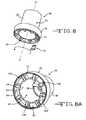
- FIG. 8is a perspective view illustrating an assembly step of the present invention.
- FIG. 8Ais a perspective view illustrating a preferred embodiment of an assembled bone cutter assembly of the present invention.
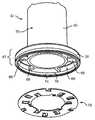
- FIG. 9is a perspective view of a preferred embodiment of a cutter disc of the present invention.
- FIG. 10is a perspective view of the cutter disc and an alternative cutter housing embodiment of the present invention.
- FIG. 10Ais a perspective view of an assembled alternate embodiment of the bone cutter assembly of the present invention shown in FIG. 10 .
- FIG. 10Bis a cross-sectional view of an assembled alternate embodiment of the bone cutter assembly of the present invention shown in FIG. 10 .
- FIG. 11is a cross-sectional view of an embodiment of the bone cutter of the present invention being used to shape the end of a bone.
- FIG. 11Ais a cross-sectional view illustrating the shaped end of a bone after using the bone cutter of the present invention.
- FIGS. 2-11Aillustrate embodiments of a bone cutter 30 of the present invention.
- the bone cutter 30comprises a cutter housing 32 , cutter blades 34 or cutter disc 78 , and a guide rod 36 ( FIGS. 11 , 11 A).
- the cutter housing 32preferably comprises two cylinders, a first cylinder 38 and a second cylinder 40 that are joined therebetween.
- the first cylinder 38comprises a first cylinder inner diameter 42 , a first cylinder outer diameter 44 , and a first cylinder wall thickness 46 therebetween.
- the second cylinder 40comprises a second cylinder inner diameter 48 , a second cylinder outer diameter 50 , and a second cylinder wall thickness 52 therebetween.
- first cylinder 38comprises a first cylinder height 54 extending from a first cylinder distal base portion 56 to a first cylinder proximal end portion 58 .
- distal base portion 56 of the first cylinder 38is co-planar with an imaginary first cylinder base plane B-B ( FIG. 4 ). This imaginary base plane B-B preferably extends outwardly from the outer diameter 44 of the first cylinder base portion 56 .
- the second cylinder 40comprises a second cylinder height 60 extending from a second cylinder distal base portion 62 to a second cylinder proximal end portion 64 .
- the distal base portion. 62 of the second cylinder 40is co-planar with an imaginary second cylinder base plane C-C ( FIG. 4 ). This imaginary base plane C-C preferably extends outwardly from the outer diameter 50 of the second cylinder base portion 62 .
- first and second cylinders 38 , 40are joined such that the outer diameter 50 of the second cylinder 40 is positioned within the inner diameter 42 of the first cylinder 38 .
- the first and second cylinders 38 , 40are further positioned such that they are co-axial to a common central longitudinal axis A-A as shown in FIGS. 2-4 , 8 , 8 A, and 10 - 11 A.
- the outer diameter 44 of the first cylinder 38ranges from about 5 cm to about 10 cm
- the inner diameter 42 of the first cylinder 38ranges from about 4.5 cm to about 9.95 cm
- the height 54 of the first cylinder 38ranges from about 1 cm to about 4 cm.
- the wall thickness 46 of the first cylinder 38preferably ranges from about 0.05 cm to about 0.5 cm.
- the height 60 of the centrally located second cylinder 40is greater than that of the height 54 of the first cylinder 38 . Furthermore, the height 60 of the centrally located second cylinder 40 ranges from about 5 cm to about 10 cm.
- the outer diameter 50 of the second cylinder 40ranges from about 3 cm to about 6 cm and the inner diameter 48 of the second cylinder 40 ranges from about 2 cm to about 6 cm.
- the wall thickness 52 of the second cylinder 40ranges from about 0.05 cm to about 0.5 cm.
- the two cylinders 38 , 40are joined together by a connector 66 that interfaces between the two cylinders 38 , 40 at a distal end portion 67 of the housing 32 as shown in FIG. 10 .
- the connector 66can be of many non-limiting forms such as a bar, a rod, a rectangle or a sphere such that one surface interfaces with the interior wall surface 68 of the inner diameter 42 of the first cylinder 38 and an opposite surface interfaces with the exterior wall surface 70 of the outer diameter 50 of the second cylinder 40 .
- a plurality of two or more connectors 66radially extend between the inner and outer diameters 42 , 50 of the first and second cylinders 38 , 40 , respectively, and join them therebetween as shown in FIG. 10 .
- the connector 66can be designed as a blade enclosure 72 such that individual insert blades 34 ( FIGS. 2-3 , and 8 - 8 A) are disposed therewithin.
- This preferred blade enclosure 72 embodimentwill be discussed in more detail.
- the housing 32is preferably constructed such that an offset rim 74 is formed by a portion of the wall thickness 46 of the first cylinder 38 .
- the depth 76 of the offset rim 74is defined by the distance between the first and second imaginary distal base planes B-B, C-C as shown in the cross sectional view of FIG. 4 .
- the offset rim 74preferably has a depth 76 that ranges from about 0.01 cm to about 0.05 cm.
- the offset rim 74preferably extends around the perimeter of the first cylinder 38 at the distal base portion 56 .
- the thickness of the offset rim 74is defined by the wall thickness 46 of the outer first cylinder 38 .
- the offset rim 74is designed to prevent the cutter blades 34 or cutter disc 78 ( FIG. 9 ) from inadvertently damaging nearby bone or tissue, particularly preventing a proximal bone or tissue from being cut or nicked.
- the housing 32could be constructed such that the first and second imaginary planes B-B, C-C are coplanar, therefore constructing a housing 32 without an offset rim 74 .
- both the first and second cylinders 38 , 40have a hollow interior 80 , 82 within their respective inner diameters 42 , 48 .
- a hollow interior 80 , 82allows for efficient removal of bone debris as the debris can freely flow through the cutter assembly 84 ( FIGS. 8 , 8 A).
- a housing 32could be constructed with a cylinder having a solid or partially solid interior.
- the cutter housing 32has a boss 86 that is positioned within the inner diameter 48 of the second cylinder 40 . More specifically, the boss 86 is centrally positioned within the inner diameter 48 of the second cylinder 40 . In a preferred embodiment, the boss 86 comprises a throughbore 88 . The boss 86 is preferably further positioned within the inner diameter 48 of the second cylinder 40 such that the throughbore 88 is co-axially aligned with the central axis A-A of the housing 32 as shown in FIGS. 2 , 4 , 8 A, and 11 - 11 A.
- the boss 86is constructed with a distal planar edge 90 .
- This distal planar edge 90is designed to act as a “stop” to prevent further advancement of the cutter 30 into the end 24 of the bone 14 .
- the boss 86is preferably positioned with the interior 82 of the second cylinder 40 such that a cut depth 92 is defined between the distal planar edge 90 of the boss 86 and the imaginary second cylinder base plane C-C. It is contemplated that this distal planar edge 90 can be positioned anywhere within the interior 82 of the centrally located second cylinder 40 to establish an optimal cut depth 92 for a particular implant (not shown). In a preferred embodiment the cut depth 92 ranges from about 2 cm to about 10 cm.
- a plurality of bars 94secure the boss 86 within the inner diameter 48 of the centrally located second cylinder 40 .
- a plurality of bars 94having a length 96 from about 4 cm to about 8 cm and a thickness 98 from about 0.5 cm to about 1 cm, fluidly extend from the interior wall surface 68 of the inner diameter 48 of the first cylinder 38 to the exterior wall surface 70 of the outer diameter 50 of the second cylinder 40 within the proximal portion 64 of the housing 32 . It is preferred that a plurality of at least two bars 94 , connect the boss 86 within the interior 82 of the second cylinder 40 .
- the housing 32be composed of a biocompatible material.
- the cutter housing 32is composed of a biocompatible thermoplastic such as, but not limited to, Acrylonitrile Butadiene Styrene (ABS), Polyarylamide (PAA), or Polyetheretherketone (PEEK).
- the series of cutter blades 34are positioned in a radial fashion about the outer diameter 50 of the second cylinder 40 as illustrated in FIGS. 8 and 8A . More specifically, these cutter insert blades 34 are positioned between the exterior surface 70 of the outer diameter 50 of the second cylinder 40 and the interior surface 68 of the inner diameter 42 of the first cylinder 38 at the distal base portion 56 of the housing 32 .
- insert blades 34 , 130comprise a blade proximal portion 100 and a blade distal portion 102 .
- the widths 104 , 106 of the proximal and distal portions 100 , 102are not necessarily equal. In a preferred embodiment, the width 106 of the distal portion 102 is greater than the width 104 of the proximal portion 100 .
- An insert blade cutting surface 108preferably extends along the distal width 106 of the insert blade 34 , 130 . In a preferred embodiment, when inserted into the bone cutter housing 32 , the plurality of these blade cutting surfaces 108 align to form an imaginary blade cutting surface plane D-D ( FIG. 4 ). It is further preferred that this imaginary blade cutting surface plane D-D reside between the imaginary first and second cylinder planes B-B, C-C.
- the distal width 106 of the insert blade 34 , 130is greater than the proximal width 104 of the blade 34 , 130 .
- This extra “width portion” of the insert cutter blade 34 , 130is defined as the blade extension portion 110 .
- the blade extension portion 110is designed such that when the cutter blade 34 , 130 is inserted into the housing 32 , the extension portion 110 protrudes past the inner diameter 48 of the second cylinder 40 towards the interior 82 of the second cylinder 40 .
- the blade extension portion 110acts as a “free end”.
- This “free end” extensionis designed to cut into the head 12 of the bone 14 .
- this “free end” extension 110defines a new diameter 112 of the bone head 12 as illustrated in FIG. 11A . If such an extension 110 were not present, the interior wall 69 of the second cylinder 40 would prevent cutting of the bone 14 .
- the blade extension 110has a width from about 0.05 cm to about 0.10 cm.
- a groove 114is preferably formed within the surface 116 of the distal end portion 102 of the insert blade 34 .
- the groove 114has a “V” shape.
- the groove 114is designed to establish a rake angle ⁇ of the insert blade 34 .
- the rake angle ⁇is defined as the intersection between the distal surface 120 of the “V” cut out portion 114 and a perpendicular line E-E to the cutting edge surface 108 as shown in FIG. 6 . It is preferred that rake angle ⁇ range from about 4° to about 30°.
- a relief angle ⁇is formed between the intersection of the distal end surface 124 of the blade 34 and a tangent line F-F to the blade cutting edge 108 . It is preferred that the relief angle ⁇ range from about 4° to about 20°.
- Each cutter blade 34 , 130is preferably positioned within the cutter blade enclosure 72 as shown in FIGS. 8 and 8A .
- the insert blade 34 , 130is positioned in the housing 32 such that the proximal end portion 104 of the insert blade 34 , 130 resides inside the blade enclosure 72 and the cutting surface 108 of the insert blade 34 , 130 lies outside the blade enclosure 72 .
- the cutting surface 108 of the insert blade 34lies parallel to an imaginary cutting plane D-D as shown in FIG. 4 .
- the imaginary cutting plane D-Dlies between the first cylinder imaginary plane B-B and the second cylinder imaginary plane C-C.
- the blade extension 110preferably is positioned towards the central axis A-A of the assembly 84 .
- each cutter blade enclosure 72has a post 126 therewithin.
- the post 126is preferably designed to snap-fit into a slot 128 within the proximal end portion 100 of the cutter blade 34 ( FIGS. 5 and 6 ). Once the post 126 snaps into the slot 128 , the insert blade 34 is locked within the cutter blade enclosure 72 .
- the insert blade 130can be designed without a groove 114 and slot 128 .
- the cutting edge 108is formed at the intersection of the side blade surface 116 and the distal end surface 124 . It is preferred that a portion of the surface 116 at the proximal end portion 100 of the insert blade 130 has a roughened finish 132 . This roughened surface finish portion 132 provides for a more secure fit when positioned within the blade enclosure 72 .
- insert blades 34 , 130are secured within the blade enclosure 72 with an induction bonding process.
- the insert blade 34 , 130can be secured by an alternate means not limited to adhesives, overmolding, press fitting, induction bonding, and the like.
- the cutting disc 78is positioned at the distal end portion 67 of the housing 32 .
- the cutting disc 78 embodimentprovides an additional means of bone removal which is illustrated in FIGS. 9-10A .
- An embodiment of this alternate cutter assembly 146is shown in FIG. 10A .
- the assembly 146 of this embodimentcomprises the housing 32 and the cutter disc 78 .
- the cutting disc 78preferably comprises an outer disc diameter 134 , an inner disc diameter 136 and a planar surface 138 therebetween.
- the cutting disc 78is positioned between the wall thickness 46 of the first cylinder 38 and the wall thickness 52 of the second cylinder 40 at the distal end portion 67 . More specifically, it is preferred that the cutting disc 78 be placed between the inner diameter 42 of the first cylinder 38 and the inner diameter 48 of the second cylinder 40 such that the planar surface 138 of the cutting disc 78 is parallel to the first and second cylinder imaginary planes B-B, C-C ( FIG. 10B ).
- a series of openings 140Positioned throughout the surface 138 of the disc 78 are a series of openings 140 . These openings 140 are preferably positioned throughout the surface 138 of the disc 78 in a helical pattern. Protruding from the opening 140 is a cutting tooth 142 .
- the cutting teeth 142are designed such that a cutting surface 144 is positioned outwardly from the planar surface 138 of the disc 78 . Alternately, the cutting surface 144 may protrude inwardly from the surface 138 of the disc 78 . In a preferred embodiment, these cutting surfaces 144 of the cutting teeth 142 align to form an imaginary cutting disc plane G-G. This imaginary plane G-G preferably resides between the first and second imaginary cylinder planes B-B, C-C ( FIG. 10B ).
- the cutter insert blades 34 , 130 and the cutting disc 78are composed of a biocompatible metal.
- biocompatible metalsinclude, but are not limited to, stainless steel, MP35N, titanium, and combinations thereof. It is most preferred that cutter blades 34 , 130 and the cutting disc 78 are composed of a 300 series stainless steel.
- the cutter housing 32is first molded from a biocompatible polymer as previously mentioned. After the housing 32 has been molded, the cutter blades 34 , 130 or cutter disc 78 are then inserted in the distal base portion 67 of the housing 32 . As previously mentioned, an induction bonding process is preferably used to secure the cutter blades 34 , 130 or cutter disc 78 to the molded assembly 84 , 146 . Alternatively, adhesives, overmolding, press fitting, and the like may also be used.
- electromagnetic currentis used to heat the blades 34 , 130 or blade disc 78 .
- Heat generated from the currentmelts the surrounding assembly polymer material, causing the material to flow and engage the cutter blades 34 , 130 or disc 78 .
- alternative processessuch as cross pinned engagements, direct insert molding, or ultrasonic insertion may also be used to strengthen the connection or act as a primary means to join the bone cutter 30 of the present invention.
- FIGS. 11 and 11Aillustrate the use of the bone cutter 30 of the present invention.
- a guide-hole 148is drilled into the end 24 of a bone 14 .
- the guide rod 36is placed into the guide-hole 148 and the cutter assembly 84 , 146 is placed over the rod 36 as shown.
- the guide rod 36is preferably positioned through the central axis A-A of the bone cutter 30 .
- the cutter 30is rotated in either a clockwise or counterclockwise direction. This rotational movement of the cutter 30 , removes bone material from the end 24 of the bone 14 with a smooth surface finish with a bone diameter 112 suitably sized for insertion of an implant (not shown). Once the bone head 12 is properly shaped, the cutter 30 and guide rod 36 are removed. An implant (not shown) is then positioned over the end 24 of the bone 14 .
- the present inventionhas many features and benefits among which are promoting proper implant fit, decreased procedural times and minimized patient trauma. While embodiments of the present invention have been described in detail, that is for the purpose of illustration, not limitation.
Landscapes
- Health & Medical Sciences (AREA)
- Surgery (AREA)
- Life Sciences & Earth Sciences (AREA)
- Biomedical Technology (AREA)
- Medical Informatics (AREA)
- Orthopedic Medicine & Surgery (AREA)
- Oral & Maxillofacial Surgery (AREA)
- Engineering & Computer Science (AREA)
- Dentistry (AREA)
- Heart & Thoracic Surgery (AREA)
- Nuclear Medicine, Radiotherapy & Molecular Imaging (AREA)
- Molecular Biology (AREA)
- Animal Behavior & Ethology (AREA)
- General Health & Medical Sciences (AREA)
- Public Health (AREA)
- Veterinary Medicine (AREA)
- Surgical Instruments (AREA)
Abstract
Description
Claims (18)
Priority Applications (2)
| Application Number | Priority Date | Filing Date | Title |
|---|---|---|---|
| US13/112,084US8876825B2 (en) | 2010-05-21 | 2011-05-20 | Disposable cylindrical cutter |
| US14/337,498US9282978B2 (en) | 2010-05-21 | 2014-07-22 | Disposable cylindrical cutter |
Applications Claiming Priority (2)
| Application Number | Priority Date | Filing Date | Title |
|---|---|---|---|
| US34697610P | 2010-05-21 | 2010-05-21 | |
| US13/112,084US8876825B2 (en) | 2010-05-21 | 2011-05-20 | Disposable cylindrical cutter |
Related Child Applications (1)
| Application Number | Title | Priority Date | Filing Date |
|---|---|---|---|
| US14/337,498DivisionUS9282978B2 (en) | 2010-05-21 | 2014-07-22 | Disposable cylindrical cutter |
Publications (2)
| Publication Number | Publication Date |
|---|---|
| US20110288554A1 US20110288554A1 (en) | 2011-11-24 |
| US8876825B2true US8876825B2 (en) | 2014-11-04 |
Family
ID=44584729
Family Applications (2)
| Application Number | Title | Priority Date | Filing Date |
|---|---|---|---|
| US13/112,084Active2031-09-06US8876825B2 (en) | 2010-05-21 | 2011-05-20 | Disposable cylindrical cutter |
| US14/337,498Active2031-07-07US9282978B2 (en) | 2010-05-21 | 2014-07-22 | Disposable cylindrical cutter |
Family Applications After (1)
| Application Number | Title | Priority Date | Filing Date |
|---|---|---|---|
| US14/337,498Active2031-07-07US9282978B2 (en) | 2010-05-21 | 2014-07-22 | Disposable cylindrical cutter |
Country Status (2)
| Country | Link |
|---|---|
| US (2) | US8876825B2 (en) |
| EP (1) | EP2387960B1 (en) |
Cited By (2)
| Publication number | Priority date | Publication date | Assignee | Title |
|---|---|---|---|---|
| US9814587B2 (en)* | 2013-03-15 | 2017-11-14 | Catalyst Orthoscience Inc. | Humeral arthroplasty |
| US11446151B2 (en)* | 2019-06-27 | 2022-09-20 | DePuy Synthes Products, Inc. | Annular cutting tools for resecting a bone graft and related methods |
Families Citing this family (3)
| Publication number | Priority date | Publication date | Assignee | Title |
|---|---|---|---|---|
| US9820757B2 (en)* | 2013-04-12 | 2017-11-21 | Greatbatch Ltd. | Instrument for reshaping the head of a femur |
| US10993729B1 (en) | 2014-07-02 | 2021-05-04 | Insurgical, Inc. | Sterile ready-to-use surgical tool and attachment system |
| US20160000449A1 (en)* | 2014-07-02 | 2016-01-07 | Peter M. Aman | Sterile ready-to-use surgical tool and attachment system |
Citations (40)
| Publication number | Priority date | Publication date | Assignee | Title |
|---|---|---|---|---|
| US1569987A (en)* | 1925-08-19 | 1926-01-19 | Lamberti Vincenzo | Hedge trimmer |
| US2832184A (en)* | 1955-03-23 | 1958-04-29 | Joseph H Beuerle | Lawn edger and trimmer |
| US3118162A (en)* | 1962-04-13 | 1964-01-21 | Karr Alexander | Wire brush stabilizer |
| US3398422A (en)* | 1968-01-25 | 1968-08-27 | Multi Clean Products Inc | Rotary brush for carpet scrubbing machine |
| US3877146A (en)* | 1973-11-28 | 1975-04-15 | Allegretti & Co | Rotating blade holder |
| US4148110A (en)* | 1975-03-02 | 1979-04-10 | Moen Asbjoern | Rotating scraping or abrading tool |
| US4211002A (en)* | 1979-02-27 | 1980-07-08 | Kirk Norbert A | Hand-held peeler |
| US4284080A (en)* | 1978-08-04 | 1981-08-18 | Orthoplant Orthopadische Implantate Gmbh & Co. Kg | Apparatus for the working of a bone which is to be provided with a shell prosthesis |
| US4306550A (en)* | 1980-02-06 | 1981-12-22 | Minnesota Mining And Manufacturing Company | Combination including femoral rasp and calcar facing reamer |
| US4335510A (en)* | 1980-06-18 | 1982-06-22 | Black & Decker, Inc. | String trimmer |
| US4547966A (en)* | 1984-08-10 | 1985-10-22 | Eden Brian W | Sprinkler head trimmer and cleaner |
| US5100267A (en) | 1991-03-13 | 1992-03-31 | Othy, Inc. | Disposable acetabular reamer cup |
| US5180384A (en)* | 1991-02-08 | 1993-01-19 | Mikhail Michael W E | Method for implanting a patellar prosthesis |
| US5205685A (en)* | 1992-10-05 | 1993-04-27 | Herbert Henry R | Hole saw |
| EP0574701A1 (en) | 1992-06-17 | 1993-12-22 | Philipp Rolf Kropf | Working tool for bones |
| US5282804A (en)* | 1991-05-08 | 1994-02-01 | Othy, Inc. | Tool driver |
| US5295992A (en)* | 1992-03-16 | 1994-03-22 | Othy, Inc. | Patella cutting system |
| US5299893A (en)* | 1991-03-13 | 1994-04-05 | Othy, Inc. | Disposable surgical cutters |
| US5336226A (en)* | 1992-08-11 | 1994-08-09 | Chapman Lake Instruments, Inc. | Bone face cutter |
| US5493783A (en)* | 1994-05-23 | 1996-02-27 | Oostendorp; William E. | Grass trimming device |
| US5876405A (en)* | 1997-09-17 | 1999-03-02 | The Anspach Effort, Inc. | Perforator |
| US5976143A (en)* | 1997-12-23 | 1999-11-02 | Johnson & Johnson Professional, Inc. | Orthopedic reaming instrument |
| US6162227A (en) | 1996-08-26 | 2000-12-19 | Plus Endoprothetik Ag | Bone cutter |
| US6277121B1 (en)* | 1998-09-09 | 2001-08-21 | Brian D. Burkinshaw | Patella reaming system |
| US6322564B1 (en)* | 1998-06-18 | 2001-11-27 | Depuy Orthopaedics, Inc. | Proximal alignment insertion guide and method therefor |
| DE20115678U1 (en) | 2001-09-24 | 2001-12-06 | Waldemar Link GmbH & Co., 22339 Hamburg | Bone cutter |
| US6588111B2 (en)* | 2001-05-10 | 2003-07-08 | Dan Williams | Undercut saw with central height adjustment |
| US20030135219A1 (en)* | 2002-01-14 | 2003-07-17 | Salyer Paul E. | Cutting edges for reamers and a method for making same |
| US20030212401A1 (en)* | 2002-05-09 | 2003-11-13 | Mark Nordman | Surgical cutter with modular blades |
| US20050039583A1 (en)* | 2003-08-22 | 2005-02-24 | Jeg, Inc | Head cover trimming system |
| US20050251145A1 (en)* | 2000-06-24 | 2005-11-10 | Yves Desarzens | Guided reamer system for reshaping bone |
| US20060111725A1 (en) | 2002-11-22 | 2006-05-25 | Jean-Francois Biegun | Accessories for removing bone material and method for making same |
| WO2008001104A2 (en) | 2006-06-29 | 2008-01-03 | O'hara John N | Debris retaining reamer |
| US7527696B1 (en)* | 2006-01-17 | 2009-05-05 | Cmk Engineering Inc. | Debris removal tool and method |
| US20090118735A1 (en)* | 2007-11-07 | 2009-05-07 | Burmeister Iii Richard Frederick | Bone mill including a base and a mill head separate from the base, the mill head including a moveable catch tray |
| US20090209963A1 (en)* | 2008-02-12 | 2009-08-20 | Amir Jamali | Device and method for allograft total hip arthroplasty |
| US20090326536A1 (en) | 2006-08-31 | 2009-12-31 | Tom Pynsent | Medical device |
| US20100004653A1 (en)* | 2006-01-17 | 2010-01-07 | Houshang Rasekhi | Self-clearing rasp system for automatic milling apparatus |
| US20100152742A1 (en)* | 2003-05-12 | 2010-06-17 | Corin Limited | Head centering jig for femoral resurfacing |
| US8152809B1 (en)* | 2005-06-15 | 2012-04-10 | Vanderbilt University | Flat cut bit for cranial perforator |
Family Cites Families (3)
| Publication number | Priority date | Publication date | Assignee | Title |
|---|---|---|---|---|
| US4059115A (en)* | 1976-06-14 | 1977-11-22 | Georgy Stepanovich Jumashev | Surgical instrument for operation of anterior fenestrated spondylodessis in vertebral osteochondrosis |
| GB2446514B (en)* | 2007-02-08 | 2011-06-08 | Precimed Sa | Holder for a surgical reamer and single use,flat reamer |
| DE102007060493A1 (en)* | 2007-12-05 | 2009-06-10 | Aesculap Ag | Attachment device for a surgical device and surgical device for cutting through a bone |
- 2011
- 2011-05-20USUS13/112,084patent/US8876825B2/enactiveActive
- 2011-05-23EPEP11167163.2Apatent/EP2387960B1/enactiveActive
- 2014
- 2014-07-22USUS14/337,498patent/US9282978B2/enactiveActive
Patent Citations (42)
| Publication number | Priority date | Publication date | Assignee | Title |
|---|---|---|---|---|
| US1569987A (en)* | 1925-08-19 | 1926-01-19 | Lamberti Vincenzo | Hedge trimmer |
| US2832184A (en)* | 1955-03-23 | 1958-04-29 | Joseph H Beuerle | Lawn edger and trimmer |
| US3118162A (en)* | 1962-04-13 | 1964-01-21 | Karr Alexander | Wire brush stabilizer |
| US3398422A (en)* | 1968-01-25 | 1968-08-27 | Multi Clean Products Inc | Rotary brush for carpet scrubbing machine |
| US3877146A (en)* | 1973-11-28 | 1975-04-15 | Allegretti & Co | Rotating blade holder |
| US4148110A (en)* | 1975-03-02 | 1979-04-10 | Moen Asbjoern | Rotating scraping or abrading tool |
| US4284080A (en)* | 1978-08-04 | 1981-08-18 | Orthoplant Orthopadische Implantate Gmbh & Co. Kg | Apparatus for the working of a bone which is to be provided with a shell prosthesis |
| US4211002A (en)* | 1979-02-27 | 1980-07-08 | Kirk Norbert A | Hand-held peeler |
| US4306550A (en)* | 1980-02-06 | 1981-12-22 | Minnesota Mining And Manufacturing Company | Combination including femoral rasp and calcar facing reamer |
| US4335510A (en)* | 1980-06-18 | 1982-06-22 | Black & Decker, Inc. | String trimmer |
| US4547966A (en)* | 1984-08-10 | 1985-10-22 | Eden Brian W | Sprinkler head trimmer and cleaner |
| US5180384A (en)* | 1991-02-08 | 1993-01-19 | Mikhail Michael W E | Method for implanting a patellar prosthesis |
| US5100267A (en) | 1991-03-13 | 1992-03-31 | Othy, Inc. | Disposable acetabular reamer cup |
| US5299893A (en)* | 1991-03-13 | 1994-04-05 | Othy, Inc. | Disposable surgical cutters |
| US5501686A (en)* | 1991-05-08 | 1996-03-26 | Othy, Inc. | Tool driver |
| US5282804A (en)* | 1991-05-08 | 1994-02-01 | Othy, Inc. | Tool driver |
| US5295992A (en)* | 1992-03-16 | 1994-03-22 | Othy, Inc. | Patella cutting system |
| EP0574701A1 (en) | 1992-06-17 | 1993-12-22 | Philipp Rolf Kropf | Working tool for bones |
| US5336226A (en)* | 1992-08-11 | 1994-08-09 | Chapman Lake Instruments, Inc. | Bone face cutter |
| US5205685A (en)* | 1992-10-05 | 1993-04-27 | Herbert Henry R | Hole saw |
| US5493783A (en)* | 1994-05-23 | 1996-02-27 | Oostendorp; William E. | Grass trimming device |
| US6162227A (en) | 1996-08-26 | 2000-12-19 | Plus Endoprothetik Ag | Bone cutter |
| US5876405A (en)* | 1997-09-17 | 1999-03-02 | The Anspach Effort, Inc. | Perforator |
| US5976143A (en)* | 1997-12-23 | 1999-11-02 | Johnson & Johnson Professional, Inc. | Orthopedic reaming instrument |
| US6322564B1 (en)* | 1998-06-18 | 2001-11-27 | Depuy Orthopaedics, Inc. | Proximal alignment insertion guide and method therefor |
| US6277121B1 (en)* | 1998-09-09 | 2001-08-21 | Brian D. Burkinshaw | Patella reaming system |
| US8057477B2 (en)* | 2000-06-24 | 2011-11-15 | Greatbatch Medical S.A. | Guided reamer system for reshaping bone |
| US20050251145A1 (en)* | 2000-06-24 | 2005-11-10 | Yves Desarzens | Guided reamer system for reshaping bone |
| US6588111B2 (en)* | 2001-05-10 | 2003-07-08 | Dan Williams | Undercut saw with central height adjustment |
| DE20115678U1 (en) | 2001-09-24 | 2001-12-06 | Waldemar Link GmbH & Co., 22339 Hamburg | Bone cutter |
| US20030135219A1 (en)* | 2002-01-14 | 2003-07-17 | Salyer Paul E. | Cutting edges for reamers and a method for making same |
| US20030212401A1 (en)* | 2002-05-09 | 2003-11-13 | Mark Nordman | Surgical cutter with modular blades |
| US20060111725A1 (en) | 2002-11-22 | 2006-05-25 | Jean-Francois Biegun | Accessories for removing bone material and method for making same |
| US20100152742A1 (en)* | 2003-05-12 | 2010-06-17 | Corin Limited | Head centering jig for femoral resurfacing |
| US20050039583A1 (en)* | 2003-08-22 | 2005-02-24 | Jeg, Inc | Head cover trimming system |
| US8152809B1 (en)* | 2005-06-15 | 2012-04-10 | Vanderbilt University | Flat cut bit for cranial perforator |
| US20100004653A1 (en)* | 2006-01-17 | 2010-01-07 | Houshang Rasekhi | Self-clearing rasp system for automatic milling apparatus |
| US7527696B1 (en)* | 2006-01-17 | 2009-05-05 | Cmk Engineering Inc. | Debris removal tool and method |
| WO2008001104A2 (en) | 2006-06-29 | 2008-01-03 | O'hara John N | Debris retaining reamer |
| US20090326536A1 (en) | 2006-08-31 | 2009-12-31 | Tom Pynsent | Medical device |
| US20090118735A1 (en)* | 2007-11-07 | 2009-05-07 | Burmeister Iii Richard Frederick | Bone mill including a base and a mill head separate from the base, the mill head including a moveable catch tray |
| US20090209963A1 (en)* | 2008-02-12 | 2009-08-20 | Amir Jamali | Device and method for allograft total hip arthroplasty |
Non-Patent Citations (1)
| Title |
|---|
| European Search Report dated Apr. 18, 2013, EP11167163. |
Cited By (6)
| Publication number | Priority date | Publication date | Assignee | Title |
|---|---|---|---|---|
| US9814587B2 (en)* | 2013-03-15 | 2017-11-14 | Catalyst Orthoscience Inc. | Humeral arthroplasty |
| US10265185B2 (en) | 2013-03-15 | 2019-04-23 | Catalyst Orthoscience Inc. | Humeral arthroplasty |
| US10925744B2 (en) | 2013-03-15 | 2021-02-23 | Catalyst Orthoscience Inc. | Humeral arthroplasty |
| US11446151B2 (en)* | 2019-06-27 | 2022-09-20 | DePuy Synthes Products, Inc. | Annular cutting tools for resecting a bone graft and related methods |
| US20220409384A1 (en)* | 2019-06-27 | 2022-12-29 | DePuy Synthes Products, Inc. | Annular cutting tools for resecting a bone graft and related methods |
| US12295854B2 (en)* | 2019-06-27 | 2025-05-13 | Medos International Sarl | Annular cutting tools for resecting a bone graft and related methods |
Also Published As
| Publication number | Publication date |
|---|---|
| EP2387960A2 (en) | 2011-11-23 |
| EP2387960A3 (en) | 2013-05-29 |
| EP2387960B1 (en) | 2017-08-30 |
| US20140330276A1 (en) | 2014-11-06 |
| US9282978B2 (en) | 2016-03-15 |
| US20110288554A1 (en) | 2011-11-24 |
Similar Documents
| Publication | Publication Date | Title |
|---|---|---|
| US9282978B2 (en) | Disposable cylindrical cutter | |
| US9107677B2 (en) | Disposable surgical hemispherical cutter for convex and concave surfaces | |
| EP2335617B1 (en) | Disposable flex reamer | |
| EP2359755B1 (en) | Disposable reamer | |
| EP3496630B1 (en) | Cutting head for an intramedullary reamer | |
| KR101455091B1 (en) | Rotary Cutting Tool with Improved Cutting and Reduced Clogging on Soft Tissue and Thin Bone | |
| EP3205294B1 (en) | Cutting heads for intramedullary reamers | |
| EP3607897B1 (en) | Cartilage removal tool | |
| US9101368B2 (en) | Methods of forming medical reamers | |
| US12114869B2 (en) | Calcar grinder | |
| EP1698290A1 (en) | Arthroscopic shaver with two pass inner blade and method of manufacturing same | |
| US11446151B2 (en) | Annular cutting tools for resecting a bone graft and related methods | |
| US6890336B2 (en) | Surgical cutter with modular blades | |
| JP5491180B2 (en) | Medical device | |
| JP5134379B2 (en) | Medical cutting tool | |
| CN108472047A (en) | Rotary cutter for the femoral bone for preparing surface replacement hip implant | |
| US9101370B2 (en) | Disposable surgical cutter for shaping the head of a femur | |
| US12232761B2 (en) | Rotary surgical shaver | |
| US20170071612A1 (en) | Surgical metal debris reduction system |
Legal Events
| Date | Code | Title | Description |
|---|---|---|---|
| AS | Assignment | Owner name:GREATBATCH LTD., NEW YORK Free format text:ASSIGNMENT OF ASSIGNORS INTEREST;ASSIGNOR:VICTOR, GARY C.;REEL/FRAME:026313/0887 Effective date:20110518 | |
| STCF | Information on status: patent grant | Free format text:PATENTED CASE | |
| CC | Certificate of correction | ||
| AS | Assignment | Owner name:MANUFACTURERS AND TRADERS TRUST COMPANY, NEW YORK Free format text:SECURITY INTEREST;ASSIGNORS:GREATBATCH, INC.;GREATBATCH LTD.;ELECTROCHEM SOLUTIONS, INC.;AND OTHERS;REEL/FRAME:036980/0482 Effective date:20151027 | |
| MAFP | Maintenance fee payment | Free format text:PAYMENT OF MAINTENANCE FEE, 4TH YEAR, LARGE ENTITY (ORIGINAL EVENT CODE: M1551) Year of fee payment:4 | |
| AS | Assignment | Owner name:GREATBATCH LTD., NEW YORK Free format text:RELEASE BY SECURED PARTY;ASSIGNOR:MANUFACTURERS AND TRADERS TRUST COMPANY;REEL/FRAME:046254/0113 Effective date:20180702 Owner name:PRECIMED INC., PENNSYLVANIA Free format text:RELEASE BY SECURED PARTY;ASSIGNOR:MANUFACTURERS AND TRADERS TRUST COMPANY;REEL/FRAME:046254/0113 Effective date:20180702 | |
| AS | Assignment | Owner name:ROYAL BANK OF CANADA, AS COLLATERAL AGENT, CANADA Free format text:SECURITY INTEREST;ASSIGNOR:BANDERA ACQUISITION, LLC;REEL/FRAME:046472/0545 Effective date:20180702 Owner name:ROYAL BANK OF CANADA, AS COLLATERAL AGENT, CANADA Free format text:SECURITY INTEREST;ASSIGNOR:BANDERA ACQUISITION, LLC;REEL/FRAME:046472/0475 Effective date:20180702 | |
| AS | Assignment | Owner name:VIANT AS&O HOLDINGS, LLC, ARIZONA Free format text:CHANGE OF NAME;ASSIGNOR:BANDERA ACQUISITION, LLC;REEL/FRAME:047221/0275 Effective date:20180824 | |
| AS | Assignment | Owner name:MICRO POWER ELECTRONICS, INC., NEW YORK Free format text:RELEASE BY SECURED PARTY;ASSIGNOR:MANUFACTURERS AND TRADERS TRUST COMPANY (AS ADMINISTRATIVE AGENT);REEL/FRAME:060938/0069 Effective date:20210903 Owner name:PRECIMED INC., NEW YORK Free format text:RELEASE BY SECURED PARTY;ASSIGNOR:MANUFACTURERS AND TRADERS TRUST COMPANY (AS ADMINISTRATIVE AGENT);REEL/FRAME:060938/0069 Effective date:20210903 Owner name:GREATBATCH-GLOBE TOOL, INC., NEW YORK Free format text:RELEASE BY SECURED PARTY;ASSIGNOR:MANUFACTURERS AND TRADERS TRUST COMPANY (AS ADMINISTRATIVE AGENT);REEL/FRAME:060938/0069 Effective date:20210903 Owner name:NEURONEXUS TECHNOLOGIES, INC., NEW YORK Free format text:RELEASE BY SECURED PARTY;ASSIGNOR:MANUFACTURERS AND TRADERS TRUST COMPANY (AS ADMINISTRATIVE AGENT);REEL/FRAME:060938/0069 Effective date:20210903 Owner name:ELECTROCHEM SOLUTIONS, INC., NEW YORK Free format text:RELEASE BY SECURED PARTY;ASSIGNOR:MANUFACTURERS AND TRADERS TRUST COMPANY (AS ADMINISTRATIVE AGENT);REEL/FRAME:060938/0069 Effective date:20210903 Owner name:GREATBATCH LTD., NEW YORK Free format text:RELEASE BY SECURED PARTY;ASSIGNOR:MANUFACTURERS AND TRADERS TRUST COMPANY (AS ADMINISTRATIVE AGENT);REEL/FRAME:060938/0069 Effective date:20210903 Owner name:GREATBATCH, INC., NEW YORK Free format text:RELEASE BY SECURED PARTY;ASSIGNOR:MANUFACTURERS AND TRADERS TRUST COMPANY (AS ADMINISTRATIVE AGENT);REEL/FRAME:060938/0069 Effective date:20210903 | |
| MAFP | Maintenance fee payment | Free format text:PAYMENT OF MAINTENANCE FEE, 8TH YEAR, LARGE ENTITY (ORIGINAL EVENT CODE: M1552); ENTITY STATUS OF PATENT OWNER: LARGE ENTITY Year of fee payment:8 | |
| AS | Assignment | Owner name:MICRO POWER ELECTRONICS, INC., NEW YORK Free format text:RELEASE BY SECURED PARTY;ASSIGNOR:MANUFACTURERS AND TRADERS TRUST COMPANY (AS ADMINISTRATIVE AGENT);REEL/FRAME:061659/0858 Effective date:20210903 Owner name:PRECIMED INC., NEW YORK Free format text:RELEASE BY SECURED PARTY;ASSIGNOR:MANUFACTURERS AND TRADERS TRUST COMPANY (AS ADMINISTRATIVE AGENT);REEL/FRAME:061659/0858 Effective date:20210903 Owner name:GREATBATCH-GLOBE TOOL, INC., NEW YORK Free format text:RELEASE BY SECURED PARTY;ASSIGNOR:MANUFACTURERS AND TRADERS TRUST COMPANY (AS ADMINISTRATIVE AGENT);REEL/FRAME:061659/0858 Effective date:20210903 Owner name:NEURONEXUS TECHNOLOGIES, INC., NEW YORK Free format text:RELEASE BY SECURED PARTY;ASSIGNOR:MANUFACTURERS AND TRADERS TRUST COMPANY (AS ADMINISTRATIVE AGENT);REEL/FRAME:061659/0858 Effective date:20210903 Owner name:ELECTROCHEM SOLUTIONS, INC., NEW YORK Free format text:RELEASE BY SECURED PARTY;ASSIGNOR:MANUFACTURERS AND TRADERS TRUST COMPANY (AS ADMINISTRATIVE AGENT);REEL/FRAME:061659/0858 Effective date:20210903 Owner name:GREATBATCH LTD., NEW YORK Free format text:RELEASE BY SECURED PARTY;ASSIGNOR:MANUFACTURERS AND TRADERS TRUST COMPANY (AS ADMINISTRATIVE AGENT);REEL/FRAME:061659/0858 Effective date:20210903 Owner name:GREATBATCH, INC., NEW YORK Free format text:RELEASE BY SECURED PARTY;ASSIGNOR:MANUFACTURERS AND TRADERS TRUST COMPANY (AS ADMINISTRATIVE AGENT);REEL/FRAME:061659/0858 Effective date:20210903 | |
| AS | Assignment | Owner name:VIANT AS&O HOLDINGS, LLC, MASSACHUSETTS Free format text:RELEASE BY SECURED PARTY;ASSIGNOR:ROYAL BANK OF CANADA;REEL/FRAME:069276/0081 Effective date:20241029 | |
| AS | Assignment | Owner name:UBS AG, STAMFORD BRANCH, CONNECTICUT Free format text:SECURITY INTEREST;ASSIGNOR:VIANT AS&O HOLDINGS, LLC;REEL/FRAME:069287/0709 Effective date:20241029 Owner name:VIANT AS&O HOLDINGS, LLC, MASSACHUSETTS Free format text:RELEASE BY SECURED PARTY;ASSIGNOR:ROYAL BANK OF CANADA;REEL/FRAME:069286/0564 Effective date:20241029 | |
| AS | Assignment | Owner name:HPS INVESTMENT PARTNERS, LLC, AS COLLATERAL AGENT, NEW YORK Free format text:SECOND LIEN PATENT SECURITY AGREEMENT;ASSIGNOR:VIANT AS&O HOLDINGS, LLC (F/K/A BANDERA ACQUISITION, LLC);REEL/FRAME:069288/0915 Effective date:20241029 | |
| AS | Assignment | Owner name:BANDERA ACQUISITION, LLC, MASSACHUSETTS Free format text:ASSIGNMENT OF ASSIGNORS INTEREST;ASSIGNOR:GREATBATCH LTD.;REEL/FRAME:069491/0456 Effective date:20180702 |