US8875544B2 - Burner apparatus, submerged combustion melters including the burner, and methods of use - Google Patents
Burner apparatus, submerged combustion melters including the burner, and methods of useDownload PDFInfo
- Publication number
- US8875544B2 US8875544B2US13/268,028US201113268028AUS8875544B2US 8875544 B2US8875544 B2US 8875544B2US 201113268028 AUS201113268028 AUS 201113268028AUS 8875544 B2US8875544 B2US 8875544B2
- Authority
- US
- United States
- Prior art keywords
- conduit
- central
- burner
- oxidant
- fuel
- Prior art date
- Legal status (The legal status is an assumption and is not a legal conclusion. Google has not performed a legal analysis and makes no representation as to the accuracy of the status listed.)
- Active, expires
Links
Images


Classifications
- C—CHEMISTRY; METALLURGY
- C03—GLASS; MINERAL OR SLAG WOOL
- C03B—MANUFACTURE, SHAPING, OR SUPPLEMENTARY PROCESSES
- C03B5/00—Melting in furnaces; Furnaces so far as specially adapted for glass manufacture
- C03B5/16—Special features of the melting process; Auxiliary means specially adapted for glass-melting furnaces
- C03B5/235—Heating the glass
- C03B5/2356—Submerged heating, e.g. by using heat pipes, hot gas or submerged combustion burners
- C—CHEMISTRY; METALLURGY
- C03—GLASS; MINERAL OR SLAG WOOL
- C03B—MANUFACTURE, SHAPING, OR SUPPLEMENTARY PROCESSES
- C03B5/00—Melting in furnaces; Furnaces so far as specially adapted for glass manufacture
- C03B5/16—Special features of the melting process; Auxiliary means specially adapted for glass-melting furnaces
- C03B5/18—Stirring devices; Homogenisation
- C—CHEMISTRY; METALLURGY
- C03—GLASS; MINERAL OR SLAG WOOL
- C03B—MANUFACTURE, SHAPING, OR SUPPLEMENTARY PROCESSES
- C03B5/00—Melting in furnaces; Furnaces so far as specially adapted for glass manufacture
- C03B5/16—Special features of the melting process; Auxiliary means specially adapted for glass-melting furnaces
- C03B5/235—Heating the glass
- C03B5/2353—Heating the glass by combustion with pure oxygen or oxygen-enriched air, e.g. using oxy-fuel burners or oxygen lances
- F—MECHANICAL ENGINEERING; LIGHTING; HEATING; WEAPONS; BLASTING
- F23—COMBUSTION APPARATUS; COMBUSTION PROCESSES
- F23D—BURNERS
- F23D11/00—Burners using a direct spraying action of liquid droplets or vaporised liquid into the combustion space
- F23D11/10—Burners using a direct spraying action of liquid droplets or vaporised liquid into the combustion space the spraying being induced by a gaseous medium, e.g. water vapour
- F23D11/108—Burners using a direct spraying action of liquid droplets or vaporised liquid into the combustion space the spraying being induced by a gaseous medium, e.g. water vapour medium and fuel intersecting downstream of the burner outlet
- F—MECHANICAL ENGINEERING; LIGHTING; HEATING; WEAPONS; BLASTING
- F23—COMBUSTION APPARATUS; COMBUSTION PROCESSES
- F23D—BURNERS
- F23D11/00—Burners using a direct spraying action of liquid droplets or vaporised liquid into the combustion space
- F23D11/10—Burners using a direct spraying action of liquid droplets or vaporised liquid into the combustion space the spraying being induced by a gaseous medium, e.g. water vapour
- F23D11/12—Burners using a direct spraying action of liquid droplets or vaporised liquid into the combustion space the spraying being induced by a gaseous medium, e.g. water vapour characterised by the shape or arrangement of the outlets from the nozzle
- F—MECHANICAL ENGINEERING; LIGHTING; HEATING; WEAPONS; BLASTING
- F23—COMBUSTION APPARATUS; COMBUSTION PROCESSES
- F23D—BURNERS
- F23D11/00—Burners using a direct spraying action of liquid droplets or vaporised liquid into the combustion space
- F23D11/36—Details
- F—MECHANICAL ENGINEERING; LIGHTING; HEATING; WEAPONS; BLASTING
- F23—COMBUSTION APPARATUS; COMBUSTION PROCESSES
- F23D—BURNERS
- F23D11/00—Burners using a direct spraying action of liquid droplets or vaporised liquid into the combustion space
- F23D11/36—Details
- F23D11/38—Nozzles; Cleaning devices therefor
- F—MECHANICAL ENGINEERING; LIGHTING; HEATING; WEAPONS; BLASTING
- F23—COMBUSTION APPARATUS; COMBUSTION PROCESSES
- F23D—BURNERS
- F23D14/00—Burners for combustion of a gas, e.g. of a gas stored under pressure as a liquid
- F23D14/20—Non-premix gas burners, i.e. in which gaseous fuel is mixed with combustion air on arrival at the combustion zone
- F—MECHANICAL ENGINEERING; LIGHTING; HEATING; WEAPONS; BLASTING
- F23—COMBUSTION APPARATUS; COMBUSTION PROCESSES
- F23D—BURNERS
- F23D14/00—Burners for combustion of a gas, e.g. of a gas stored under pressure as a liquid
- F23D14/32—Burners for combustion of a gas, e.g. of a gas stored under pressure as a liquid using a mixture of gaseous fuel and pure oxygen or oxygen-enriched air
- F—MECHANICAL ENGINEERING; LIGHTING; HEATING; WEAPONS; BLASTING
- F23—COMBUSTION APPARATUS; COMBUSTION PROCESSES
- F23D—BURNERS
- F23D14/00—Burners for combustion of a gas, e.g. of a gas stored under pressure as a liquid
- F23D14/46—Details
- F23D14/48—Nozzles
- F—MECHANICAL ENGINEERING; LIGHTING; HEATING; WEAPONS; BLASTING
- F23—COMBUSTION APPARATUS; COMBUSTION PROCESSES
- F23D—BURNERS
- F23D14/00—Burners for combustion of a gas, e.g. of a gas stored under pressure as a liquid
- F23D14/46—Details
- F23D14/48—Nozzles
- F23D14/58—Nozzles characterised by the shape or arrangement of the outlet or outlets from the nozzle, e.g. of annular configuration
- F—MECHANICAL ENGINEERING; LIGHTING; HEATING; WEAPONS; BLASTING
- F23—COMBUSTION APPARATUS; COMBUSTION PROCESSES
- F23D—BURNERS
- F23D14/00—Burners for combustion of a gas, e.g. of a gas stored under pressure as a liquid
- F23D14/46—Details
- F23D14/62—Mixing devices; Mixing tubes
- F23D14/64—Mixing devices; Mixing tubes with injectors
- F—MECHANICAL ENGINEERING; LIGHTING; HEATING; WEAPONS; BLASTING
- F23—COMBUSTION APPARATUS; COMBUSTION PROCESSES
- F23D—BURNERS
- F23D14/00—Burners for combustion of a gas, e.g. of a gas stored under pressure as a liquid
- F23D14/46—Details
- F23D14/72—Safety devices, e.g. operative in case of failure of gas supply
- F23D14/78—Cooling burner parts
- C—CHEMISTRY; METALLURGY
- C03—GLASS; MINERAL OR SLAG WOOL
- C03B—MANUFACTURE, SHAPING, OR SUPPLEMENTARY PROCESSES
- C03B2211/00—Heating processes for glass melting in glass melting furnaces
- C03B2211/20—Submerged gas heating
- C03B2211/22—Submerged gas heating by direct combustion in the melt
- C03B2211/23—Submerged gas heating by direct combustion in the melt using oxygen, i.e. pure oxygen or oxygen-enriched air
- C—CHEMISTRY; METALLURGY
- C03—GLASS; MINERAL OR SLAG WOOL
- C03B—MANUFACTURE, SHAPING, OR SUPPLEMENTARY PROCESSES
- C03B2211/00—Heating processes for glass melting in glass melting furnaces
- C03B2211/40—Heating processes for glass melting in glass melting furnaces using oxy-fuel burners
- C03B2211/60—Heating processes for glass melting in glass melting furnaces using oxy-fuel burners oxy-fuel burner construction
- F—MECHANICAL ENGINEERING; LIGHTING; HEATING; WEAPONS; BLASTING
- F23—COMBUSTION APPARATUS; COMBUSTION PROCESSES
- F23D—BURNERS
- F23D2900/00—Special features of, or arrangements for burners using fluid fuels or solid fuels suspended in a carrier gas
- F23D2900/00006—Liquid fuel burners using pure oxygen or oxygen-enriched air as oxidant
- Y—GENERAL TAGGING OF NEW TECHNOLOGICAL DEVELOPMENTS; GENERAL TAGGING OF CROSS-SECTIONAL TECHNOLOGIES SPANNING OVER SEVERAL SECTIONS OF THE IPC; TECHNICAL SUBJECTS COVERED BY FORMER USPC CROSS-REFERENCE ART COLLECTIONS [XRACs] AND DIGESTS
- Y02—TECHNOLOGIES OR APPLICATIONS FOR MITIGATION OR ADAPTATION AGAINST CLIMATE CHANGE
- Y02E—REDUCTION OF GREENHOUSE GAS [GHG] EMISSIONS, RELATED TO ENERGY GENERATION, TRANSMISSION OR DISTRIBUTION
- Y02E20/00—Combustion technologies with mitigation potential
- Y02E20/34—Indirect CO2mitigation, i.e. by acting on non CO2directly related matters of the process, e.g. pre-heating or heat recovery
- Y02E20/344—
- Y—GENERAL TAGGING OF NEW TECHNOLOGICAL DEVELOPMENTS; GENERAL TAGGING OF CROSS-SECTIONAL TECHNOLOGIES SPANNING OVER SEVERAL SECTIONS OF THE IPC; TECHNICAL SUBJECTS COVERED BY FORMER USPC CROSS-REFERENCE ART COLLECTIONS [XRACs] AND DIGESTS
- Y10—TECHNICAL SUBJECTS COVERED BY FORMER USPC
- Y10T—TECHNICAL SUBJECTS COVERED BY FORMER US CLASSIFICATION
- Y10T137/00—Fluid handling
- Y10T137/8593—Systems
- Y10T137/87249—Multiple inlet with multiple outlet
Definitions
- the present disclosurerelates generally to the field of combustion burners and methods of use, and more specifically to burners, submerged combustion melters, and methods of their use, particularly for melting glass forming materials.
- Oxy-fuel burnershave been used for many years in the glass industry in general especially in the fiberglass, TV glass, and container glass industry segments.
- oxy-fuel fired float furnacesThere are few complete oxy-fuel fired float furnaces in the operation today and they have been using retrofit oxy-fuel burners designed specifically for smaller container or fiberglass furnaces. These conversions were most likely made to meet emissions standards.
- Known oxy-fuel burnersare predominately nozzle mix designs and avoid premixing for safety reasons due to the increased reactivity of using oxygen as the oxidant versus air.
- Known oxy-fuel burners for submerged combustionare fixed designs, such that once built, they are not easily modified, for example for use with varying melter feeds, fuels, and oxidants.
- burner apparatus and processes of useare described that may allow tuning of one or more burner parameters using a burner insert.
- Geometric features of the insertin some embodiments combined with geometric features of other components of the burners, may provide the ability to control the depth of fuel and oxidant interaction below the overall exit of the burner.
- a first aspect of the disclosureis an apparatus, the apparatus comprising:
- a first conduitcomprising a first end, a second end, a longitudinal bore having a longitudinal axis, and an external surface
- a second conduitsubstantially concentric with the first conduit, the second conduit comprising a first end, a second end, and an internal surface;
- first and second conduitsconfigured to form a primary annulus between the external surface of the first conduit and the internal surface of the second conduit
- an adjustable structurecomprising a body having an upper surface, a lower surface, a circumferential surface abutting a portion of the internal surface of the second conduit, and a generally cylindrical central hub concentric with the longitudinal axis, the structure adjustable axially in relation to and removably attached to the first end of the first conduit via the hub, the hub defining a central passage having an exit at the upper surface, the body comprising one or more non-central through passages extending from the lower to the upper surface, the non-central passages configured such that flow of a first fluid through the non-central passages causes the first fluid to intersect a flow of a second fluid in a mixing region above the upper surface of the body.
- a second aspect of the disclosureis an adjustable burner apparatus, comprising:
- a first conduitcomprising a first end, a second end, a longitudinal bore having a longitudinal axis, and an external surface, the first end comprising threads on the external surface
- a second conduitsubstantially concentric with the first conduit, the second conduit comprising a first end, a second end, and an internal surface
- first and second conduitsconfigured to form a primary annulus between the external surface of the first conduit and the internal surface of the second conduit
- a bodyhaving an upper surface, a lower surface, a circumferential surface abutting a portion of the internal surface of the second conduit, and a generally cylindrical central hub concentric with the longitudinal axis, the structure adjustable axially in relation to and threadedly attached to the threads of first end of the first conduit via the hub, the hub defining a central passage having an exit at the upper surface, the body comprising one or more non-central through passages extending from the lower to the upper surface, the non-central passages configured such that flow of a first fluid through the non-central passages causes the first fluid to intersect a flow of a second fluid in a mixing region above the upper surface of the body;
- a third substantially concentric conduitcomprising a first end, a second end, and an internal surface, the internal surface of the third conduit forming, with an exterior surface of the second conduit, a secondary annulus external to the primary annulus;
- the first end of the third conduitextending beyond the first end of the second conduit, the first end of the second conduit extending beyond the first end of the first conduit, and the secondary annulus is capped by an end cap connecting the first end of the second conduit and the first end of the third conduit;
- a third aspect of the disclosureare methods, comprising:
- the structurecomprising a body having an upper surface, a lower surface, a circumferential surface abutting a portion of an internal surface of the second conduit, and a generally cylindrical central hub concentric with a longitudinal axis of the inner conduit, the structure adjustable axially in relation to and removably attached to a first end of the first conduit via the hub, the hub defining the central passage having an exit at the upper surface, the body comprising the plurality of non-central through passages extending from the lower to the upper surface, the non-central passages configured such that flow of oxidant through the non-central passages causes the oxidant to intersect flow of the fuel in a mixing region above the upper surface of the body.
- a fourth aspect of this disclosureare methods of producing molten glass comprising:
- the structurecomprising a body having an upper surface, a lower surface, a circumferential surface abutting a portion of an internal surface of the second conduit, and a generally cylindrical central hub concentric with a longitudinal axis of the inner conduit, the structure adjustable axially in relation to and removably attached to a first end of the first conduit via the hub, the hub defining the central passage having an exit at the upper surface, the body comprising the plurality of non-central through passages extending from the lower to the upper surface, the non-central passages configured such that flow of oxidant through the non-central passages causes the oxidant to intersect flow of the fuel in a mixing region above the upper surface of the body;
- Certain methods within the disclosureinclude methods wherein the oxidant may be an oxygen stream comprising at least 90 mole percent oxygen, and the fuel may be a gaseous fuel, the gaseous fuel selected from the group consisting of methane, natural gas, liquefied natural gas, propane, carbon monoxide, hydrogen, steam-reformed natural gas, atomized oil or mixtures thereof.
- the gaseous fuelselected from the group consisting of methane, natural gas, liquefied natural gas, propane, carbon monoxide, hydrogen, steam-reformed natural gas, atomized oil or mixtures thereof.
- FIGS. 1 and 2are cross-sectional views of two burner apparatus within the present disclosure
- FIG. 3Ais a cross-sectional view of one embodiment of an adjustable, removable component of the burners of FIGS. 1 and 2 taken along the line A-A of FIG. 3B , which is a plan view of the same component;
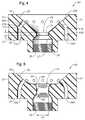
- FIGS. 4 and 5are cross-sectional views of two other embodiments of adjustable, removable burner components of the present disclosure.
- FIG. 6is a side-elevation view, partially in cross-section of a submerged combustion melter in accordance with the present disclosure, including two burners of the disclosure.
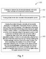
- FIGS. 7 and 8are logic diagrams of two methods in accordance with the present disclosure.
- fuelmeans a combustible composition comprising a major portion of, for example, methane, natural gas, liquefied natural gas, propane, atomized oil or the like (either in gaseous or liquid form). Fuels useful in the disclosure may comprise minor amounts of non-fuels therein, including oxidants, for purposes such as premixing the fuel with the oxidant, or atomizing liquid fuels.
- fuelincludes gaseous fuels, liquid fuels, flowable solids, such as powdered carbon or particulate material, waste materials, slurries, and mixtures or other combinations thereof.
- the gaseous fuelmay be selected from the group consisting of methane, natural gas, liquefied natural gas, propane, carbon monoxide, hydrogen, steam-reformed natural gas, atomized oil or mixtures thereof.
- Oxidantmeans air, or compositions comprising the same molar concentration of oxygen as air, while the term “oxygen” means a gas with an oxygen molar concentration of at least 50%.
- oxygenmeans a gas with an oxygen molar concentration of at least 50%.
- Such oxidantsinclude oxygen-enriched air containing at least 50% vol., oxygen such as “industrially” pure oxygen (99.5%) produced by a cryogenic air separation plant or non-pure oxygen produced by an adsorption process or membrane permeation process (about 90% vol. oxygen or more).
- Conduits and adjustable, changeable, removable bodies used in burners of the present disclosuremay be comprised of metal, ceramic, ceramic-lined metal, or combination thereof.
- Suitable metalsinclude stainless steels, for example, but not limited to, 306 and 316 steel, as well as titanium alloys, aluminum alloys, and the like.
- coolingantmay include any heat transfer fluid and may be any gaseous, liquid, or some combination of gaseous and liquid composition that functions or is capable of being modified to function as a heat transfer fluid.
- Gaseous heat transfer fluidsmay be selected from air, including ambient air and treated air (for example, air treated to remove moisture), inorganic gases, such as nitrogen, argon, and helium, organic gases such as fluoro-, chloro- and chlorofluorocarbons, including perfluorinated versions, such as tetrafluoromethane, and hexafluoroethane, and tetrafluoroethylene, and the like, and mixtures of inert gases with small portions of non-inert gases, such as hydrogen.
- inorganic gasessuch as nitrogen, argon, and helium
- organic gasessuch as fluoro-, chloro- and chlorofluorocarbons, including perfluorinated versions, such as tetrafluoromethane, and hexafluoroethan
- Heat transfer liquidsmay be selected from liquids that may be organic, inorganic, or some combination thereof, for example, salt solutions, glycol solutions, oils and the like. Other possible heat transfer fluids include steam (if cooler than the expected glass melt temperature), carbon dioxide, or mixtures thereof with nitrogen. Heat transfer fluids may be compositions comprising both gas and liquid phases, such as the higher chlorofluorocarbons.
- the sources of oxidant and fuelmay be one or more conduits, pipelines, storage facility, cylinders, or, in embodiments where the oxidant is air, ambient air.
- Oxygen-enriched oxidantsmay be supplied from a pipeline, cylinder, storage facility, cryogenic air separation unit, membrane permeation separator, or adsorption unit such as a vacuum swing adsorption unit.
- Certain burner and melter embodimentsmay comprise a source of oxidant fluidly connected to the second conduit for routing the oxidant to the primary annulus, wherein the oxidant is selected from the group consisting of air and oxygen-enriched air, and a source of fuel fluidly connected to the second end of the first conduit for routing the fuel to the longitudinal bore of the first conduit.
- Certain apparatusmay include a third substantially concentric conduit comprising a first end, a second end, and an internal surface, the internal surface of the third conduit forming, with an exterior surface of the second conduit, a secondary annulus external to the primary annulus.
- the first end of the conduitmay extend beyond the first end of the second conduit, the first end of the second conduit may extend beyond the first end of the first conduit, and the secondary annulus may be capped by an end cap connecting the first end of the second conduit and the first end of the third conduit.
- burner flame temperaturemay be controlled by monitoring one or more parameters selected from velocity of the fuel, velocity of the primary oxidant, mass flow rate of the fuel, mass flow rate of the primary oxidant, energy content of the fuel, temperature of the fuel as it enters the burner, temperature of the primary oxidant as it enters the burner, temperature of the effluent, pressure of the primary oxidant entering the burner, humidity of the oxidant, burner geometry, combustion ratio, and combinations thereof.
- Exemplary apparatus and methods of the disclosuremay comprise a combustion controller which receives one or more input parameters selected from velocity of the fuel, velocity of the primary oxidant, mass flow rate of the fuel, mass flow rate of the primary oxidant, energy content of the fuel, temperature of the fuel as it enters the burner, temperature of the primary oxidant as it enters the burner, pressure of the oxidant entering the burner, humidity of the oxidant, burner geometry, oxidation ratio, temperature of the effluent and combinations thereof, and may employ a control algorithm to control combustion temperature based on one or more of these input parameters.
- FIGS. 1 and 2are cross-sectional views of two burner apparatus embodiments 100 and 200 within the present disclosure, which are similar except that embodiment 100 is configured to employ air as oxidant, and embodiment 200 is configured to employ an oxygen-enriched oxidant.
- Embodiments 100 and 200include an inner or first conduit 2 having an inlet 3 , and an outer or second conduit 4 having an inlet 5 .
- Inner conduit 2defines a longitudinal bore 6 having a longitudinal axis A1, and inner conduit 2 and outer conduit 4 define a primary annulus 8 between them.
- a third conduit 10forms an outer body of burners 100 and 200 , with a cavity or secondary annulus 12 formed between third conduit 12 and second conduit 4 .
- An end cap 13defines an upper tip 11 of burner 100 and burner 200 , which may be generally doughnut-shaped, or other shape. End cap 13 may be integral with outer conduit 10 as illustrated, or may be a separate component attached to outer conduit 10 and inner conduit 4 via threads, screws, rivets, and the like.
- a lower plate 14is included in both embodiments 100 and 200 , with slight structural differences, and may include threads 19 or other removable fastener to secure plate 14 and inner conduit 2 into burners 100 and 200 .
- Inlets 16 , 18are provided in embodiment 100 for aspirating air into burner 100 , as well as coolant fluid inlet 20 and outlet 22 in outer conduit 10 .
- Embodiments employing more than one coolant inlet and more than one coolant outletare considered within the disclosure, but may not be necessary in all circumstances.
- Embodiment 200includes a plenum 42 for delivering a fluid into primary annulus 8 , although plenum 42 may not be necessary in all embodiments.
- plenum 42may not be necessary in all embodiments.
- oxygenis used as an oxidant
- the present disclosurecontemplates embodiments where two or more oxygen supply conduits feed primary annulus 8 .
- FIGS. 1-3Another component of burner embodiments of the present disclosure is an adjustable, changeable and removable structure or insert, designated 24 in FIGS. 1-3 .
- Body 24is adjustable in the sense that threads 28 or other connectors to inner conduit 2 allow variation of the axial position of insert 24 .
- physical parameters of insert 24may be changed, as discussed herein.
- the entire insertmay be removed and replaced with another insert of same or different dimensions if desired.
- Insert 24includes a body 33 having a central hub 26 that is, in certain embodiments, parallel to longitudinal axis A1, but not necessarily so, hub 26 including a central passage having an exit 25 that is, in certain embodiments, perpendicular to longitudinal axis A1, but not necessarily so.
- Body 33includes an upper surface 36 and a lower surface 38 , and one or more non-central passages 34 . In FIGS. 1-3 , two of the non-central passages 34 A and 34 B are visible.
- Upper surface 36helps define, along with end cap 13 , a mixing region 9 where fluids emanating from central exit 25 , which may be a fuel stream, and non-central passages 34 , which may be oxidant streams, at least partially mix.
- the streamsmay be switch in certain embodiments (in other words, fuel may traverse one or more non-central passages 34 while oxidant emanates from central exit 25 ).
- the flame shapemay be broader and the velocity of the combustion products lower in the vertical direction to enable more combustion and energy release lower in the molten glass pool to enhance efficiency.
- Body 24further includes a circumferential surface 37 that is adjacent a portion of the inner surface of second conduit 4 , near the upper end of second conduit 4 .
- body 24 of embodiments 100 and 200may include a circumferential lip 40 that abuts against an overhang portion 15 of end cap 13 .
- End cap 13has a length or height L 1
- lip 40has a length L 2 from overhang portion 15 to upper surface 36 of body 24 , where L 2 may range from about 0.25 inch to about 2 inches.
- Circumferential lip extension 40extends away from upper surface 36 of body 24 and generally parallel to longitudinal axis L 1 .
- End cap 13may extend above exit 25 of the substantially central passage of hub 26 a distance L 1 , which may range from about 0.5 inch to about 6 inches.
- Vertical connector section 29may have a length L 3 ranging from about 0.25 inch to about 1 inch.
- exit 25 of the substantially central passagehas a diameter L 4 .
- L 4may range from about 0.25 inch to about 3.0 inches.
- Lengths L 1 , L 2 , L 3 , and L 4are parameters that may be changeable and/or adjustable (as those terms are defined herein) in certain embodiments to achieve desired results, for example flame length, and may be interdependent.
- length L 1may be adjustable and changeable, while lengths L 2 , L 3 , and L 4 are only changeable from burner to burner.
- Hub 26includes, in embodiments 100 and 200 , an angled or tapered section 27 connecting exit 25 and a vertical connector section 29 that connects angled section 27 with a threaded section 28 . Threads on threaded section 28 mate with corresponding threads 30 on an upper end 32 of inner conduit 2 . This threaded connection allows removal of insert 24 and/or adjustment of burner parameters, as discussed further herein.
- FIGS. 1-3illustrate three angles ⁇ , ⁇ , and ⁇ , one or more of which may be changeable features in burners of the present disclosure.
- the word “changeable”, when referring to a burner featuremeans that that feature may be physically different from burner to burner by machining or molding, for example, while the term “adjustable” means that a feature of a burner may actually be varied without making physical modifications to the burner.
- Angle ⁇is an angle that upper surface 36 of body 33 makes with longitudinal axis L 1 , and may range from about 45 to about 90 degrees. As illustrated in embodiments 100 and 200 of FIGS.
- the non-central passagesare generally linear and angled at an angle ⁇ measured from the longitudinal axis, the ⁇ angle ranging from about 10 degrees to about 45 degrees.
- the substantially central passagemay comprise an angled section 27 and a vertical connector section 29 connecting angled section 27 with threaded section 28 of hub 26 .
- Angled section 27may form an angle ⁇ to longitudinal axis L 1 ranging from about 10 degrees to about 45 degrees.
- FIG. 3Ais a cross-sectional view of embodiment 24 of an adjustable, removable component of the burners of FIGS. 1 and 2 taken along the line A-A of FIG. 3B , which is a plan view of the same embodiment.
- FIGS. 4 and 5are cross-sectional views of two other embodiments of adjustable, removable burner components of the present disclosure.
- the non-central passagesmay comprise a vertical section 44 A, 44 B, and an angled section 46 A, 46 B.
- Vertical section 44 A, 44 Bbegins at lower surface 38 of body 24 and intersects angled section 46 A, 46 B, respectively, in body 24 at position 47 A, 47 B, which may vary from burner to burner in accordance with the present disclosure.
- Angled section 46 A, 46 Bends at upper surface 36 of body 24 .
- Another optional feature of burners of the present disclosureis a vertical extension 31 connecting angled section 27 with exit 25 .
- the length of vertical section 31designated L 5 , may be another feature of burners of the present disclosure that may be changed to affect burner operation.
- L 5may range from 0 to about 3 inches, or from about 0.25 to about 2 inches.
- the non-central passagesmay be smoothly curved passages 34 A, 34 B.
- the substantially central passagecomprises a venturi nozzle 62 comprising a converging section 64 and a diverging section 66 , where diverging section 66 is positioned downstream of converging section 64 and fluidly connects converging section 64 with nozzle exit 25 .
- Converging section 64defines a throat having a diameter L 6 , another feature that may be changed in burners of the present disclosure.
- L 6may range from about 0.25 inch to about 2 inches, or form 0.25 inch to about 1 inch.
- FIG. 6is a side-elevation view, partially in cross-section, of a submerged combustion melter embodiment 70 in accordance with the present disclosure, positioned on a plant floor or other surface 72 , including two burners 200 A and 200 B of the disclosure. More than or less than two burners of the present disclosure may be used, as well as burners of other designs, as long as one burner of the present disclosure is present.
- Melter 70includes sidewalls 78 , a floor 80 , a roof 82 , an exhaust chute 76 , and a glass melt exit 92 .
- a glass-forming material feed bin 74may be attached to melter sidewall 78 .
- One or more burners 200may be in one or more sidewalls 78 , as long as the flame and/or products of combustion emanate below surface 91 of melt 90 .
- Burners 200may be positioned in a sidewalls 78 or floor 80 of a submerged combustion melter apparatus such that the longitudinal axis A1 ( FIGS. 1-3 ) makes an angle to the side panel 78 or floor 80 of the melter ranging from about 30 to about 90 degrees.
- Sidewalls 78 , floor 80 , and roof 82are typically composed of ceramic or other refractory material.
- FIGS. 7 and 8are logic diagrams of two method embodiments in accordance with the present disclosure.
- the method of embodiment 300 of FIG. 7comprises flowing an oxidant into an annulus between inner and outer conduits of a concentric conduit burner, box 102 , and flowing a fuel to the inner conduit of the concentric burner, box 104 .
- Method embodiment 300further comprises flowing the oxidant through a plurality of non-central passages in an adjustable, removable structure, and the fuel through a central passage in the adjustable removable structure, box 106 .
- the structurecomprises a body having an upper surface, a lower surface, a circumferential surface abutting a portion of an internal surface of the second conduit, and a generally cylindrical central hub concentric with a longitudinal axis of the inner conduit, the structure adjustable axially in relation to and removably attached to a first end of the first conduit via the hub, the hub defining the central passage having an exit at the upper surface, the body comprising the plurality of non-central through passages extending from the lower to the upper surface, the non-central passages configured such that flow of oxidant through the non-central passages causes the oxidant to intersect flow of the fuel in a mixing region above the upper surface of the body.
- Embodiment 400is a method of producing molten glass, and comprises the steps of flowing an oxidant into an annulus between inner and outer conduits of a concentric conduit burner, box 402 , and flowing a fuel to the inner conduit of the concentric burner, box 404 .
- Method embodiment 400then comprises flowing the oxidant through a plurality of non-central oxidant passages in an adjustable, removable structure, and the fuel through a central fuel passage in the adjustable removable structure, box 406 .
- the structurecomprises a body having an upper surface, a lower surface, a circumferential surface abutting a portion of an internal surface of the second conduit, and a generally cylindrical central hub concentric with a longitudinal axis of the inner conduit, the structure adjustable axially in relation to and removably attached to a first end of the first conduit via the hub, the hub defining the central passage having an exit at the upper surface, the body comprising the plurality of non-central through passages extending from the lower to the upper surface, the non-central passages configured such that flow of oxidant through the non-central passages causes the oxidant to intersect flow of the fuel in a mixing region above the upper surface of the body.
- Method embodiment 400then comprises combusting at least some of the fuel in the mixing region, box 408 , to form a flame and combustion products, the mixing region defined by the upper surface of the body and a burner extension, wherein the exits of the non-central oxidant passages and the exit of the central fuel passage are recessed from an exit of the burner extension.
- the burnerdirects the flame and combustion products into partially molten glass forming materials above the mixing region, box 410 .
- oxidantmay be fed to the primary annulus, and a fuel to the longitudinal bore of the first conduit.
- inorganic glass-forming materialis charged to the melter.
- the mass flow rate of the inorganic materialfor example glass, is a function of the composition of the feed material, desired composition, viscosity, and temperature of the molten glass, the flame temperature of the burner(s), the burner geometry, for example burner exit, nozzle exit, and non-central passages sizes, the pressure in the mixing region of the burner, and other parameters.
- the process operating conditionsare generally not independent values but have some degree of interaction. Oxygen-enhanced oxidant/fuel melting is markedly different than the traditional air-fuel melting processes.
- the general principleis to operate combustion in the mixing region of the burner in a manner that replaces some of the air with a separate source of oxygen.
- the overall combustion ratiomay not change.
- the process of combining fuel and oxygen-enriched oxidantwill, in most embodiments, primarily occur in the mixing region, after the gases have passed over a flame arrestor safety device. Varying the oxygen content of the oxidant can control the flame temperature of the combustion gases.
- non-central passages 34 and central passage through hub 26may vary widely, but generally may range from about 0.25 inch to about 10 inches, or from about 0.5 inch to about 3 inches, while the diameter of the non-central passages 34 may range from about 1/32 inch up to 1 inch, or from about 0.25 inch up to about 0.5 inch, depending on the number and location of non-central passages 34 .
- the greater the number of non-central passages 34generally the smaller their diameter, although this may not be so in every embodiment.
- the greater the diameter of the central passage through hub 26generally the larger the diameter, or greater number, or both of non-central passages 34 .
- the ratio of number of non-central oxidant passages 34 to central fuel passage through hub 26may range from about 2 to 1 to about 30 to 1, or from about 4 to 1 to about 10 to 1.
- the non-central passages 34may all be circular in cross-section and have the same diameter; in other embodiments they may not. Apparatus within this disclosure include those wherein the non-central conduits 34 may all be equal in length, although the disclosure is not so limited.
- the diameters of the central and non-central passagesmay adjusted in accordance with a number of factors such as glass depth, system pressure drops, and burner outputs.
- the inner conduit 2may have an inner diameter (ID) ranging from about 1 inch up to about 5 inches (2.5 cm to 13 cm), or from about 2 inches up to about 4 inches (5 cm to 10 cm).
- IDinner diameter
- the total quantities of fuel and oxidant used by burners of the present disclosuremay be such that the flow of oxygen may range from about 0.9 to about 1.2 of the theoretical stoichiometric flow of oxygen necessary to obtain the complete combustion of the fuel flow. Another expression of this statement is that the combustion ratio may range from about 0.9 to about 1.2.
- the velocity of the fuel in the various burner embodiments of the present disclosuredepends on the burner geometry used, but generally is at least about 15 meters/second (m/s).
- the upper limit of fuel velocitydepends primarily on the desired penetration of flame and/or combustion products into the glass melt and the geometry of the burner; if the fuel velocity is too low, the flame temperature may be too low, providing inadequate temperature in the melter, which is not desired, and if the fuel flow is too high, flame and/or combustion products might impinge on a melter wall or roof, or cause carryover of melt into the exhaust, or be wasted, which is also not desired.
- Oxidant velocityshould be monitored so that flame and/or combustion products do not impinge on a melter wall or roof, or cause carryover of melt into the exhaust, or be wasted. Oxidant velocities depend on fuel flow rate and fuel velocity, but in general should not exceed about 200 ft/sec at 400 scfh flow rate. The pressure in mixing region 9 of burners in accordance with the present disclosure should not exceed about 10 psig.
- certain burner embodiments of this disclosuremay also be provided with stabilization of the flame with an auxiliary injection of fuel and/or oxidant gases.
- a portion of the oxidantmay be premixed with fuel as a primary oxidant, usually air, in conduit 2 , in addition to a secondary oxidant injection in primary annulus 8 .
- Apparatus and methods of the present disclosureare intended to be used, for example, to replace combustion burners in already existing melters, and/or to be used as the main source of energy in new submerged combustion melters.
- Conduits and adjustable, changeable, removable bodies used in burners of the present disclosuremay be comprised of metal, ceramic, ceramic-lined metal, or combination thereof.
- Suitable metalsinclude stainless steels, for example, but not limited to, 306 , 316 , as well as titanium alloys, aluminum alloys, and the like.
- High-strength materials like C-110 and C-125 metallurgies that are NACE qualifiedmay be employed. (As used herein, “NACE” refers to the corrosion prevention organization formerly known as the National Association of Corrosion Engineers, now operating under the name NACE International, Houston, Tex.)
- Use of high strength steel and other high strength materialsmay significantly reduce the wall thickness required, reducing weight of the burners.
- Threaded connectionsmay eliminate the need for 3 rd party forgings and expensive welding processes—considerably improving system delivery time and overall cost. It will be understood, however, that the use of 3 rd party forgings and welding is not ruled out for burners described herein, and may actually be preferable in certain situations. The skilled artisan, having knowledge of the particular application, pressures, temperatures, and available materials, will be able design the most cost effective, safe, and operable burners for each particular application without undue experimentation.
- suitable materialsmay include fused zirconia (ZrO 2 ), fused cast AZS (alumina-zirconia-silica), rebonded AZS, or fused cast alumina (Al 2 O 3 ).
- ZrO 2fused zirconia
- fused cast AZSalumina-zirconia-silica
- rebonded AZSrebonded AZS
- fused cast aluminaAl 2 O 3
- a combustion process control schememay be employed.
- a master controllermay be employed, but the disclosure is not so limited, as any combination of controllers could be used.
- the controllermay be selected from PI controllers, PID controllers (including any known or reasonably foreseeable variations of these), and may compute a residual equal to a difference between a measured value and a set point to produce an output to one or more control elements.
- the controllermay compute the residual continuously or non-continuously.
- Other possible implementations of the disclosureare those wherein the controller comprises more specialized control strategies, such as strategies selected from feed forward, cascade control, internal feedback loops, model predictive control, neural networks, and Kalman filtering techniques.
- Sensorsmay be provided for the following parameters, which are merely exemplary examples: V fuel , velocity of fuel entering burner; V PO , velocity of primary oxidant entering burner; V SO , velocity of secondary oxidant entering burner; M fuel , mass flow rate of fuel entering burner; M PO , mass flow rate of primary oxidant entering burner; T fuel , temperature of fuel entering burner; T PO , temperature of primary oxidant entering burner; P PO , pressure of primary oxidant entering burner; H PO , humidity of primary oxidant.
- Outputsmay be provided for the following parameters, which are merely exemplary: V fuel , velocity of fuel entering burner; V PO , velocity of primary oxidant entering burner; M fuel , mass flow rate of fuel entering burner; M SO , mass flow rate of secondary oxidant entering burner; T fuel , temperature of fuel entering burner; T PO , temperature of primary oxidant entering burner; P SO , pressure of secondary oxidant entering burner; M EFF (or M HTF ), mass flow rate of hot effluent (or heat transfer fluid).
- Other parametersmay be included as inputs, such as burner geometry, and combustion ratio, melt viscosity, and the like.
- controlmeans to verify or regulate by comparing with a standard or desired value.
- Controlmay be closed loop, feedback, feed-forward, cascade, model predictive, adaptive, heuristic and combinations thereof.
- controllermeans a device at least capable of accepting input from sensors and meters in real time or near-real time, and sending commands directly to burner control elements, and/or to local devices associated with burner control elements able to accept commands.
- a controllermay also be capable of accepting input from human operators; accessing databases, such as relational databases; sending data to and accessing data in databases, data warehouses or data marts; and sending information to and accepting input from a display device readable by a human.
- a controllermay also interface with or have integrated therewith one or more software application modules, and may supervise interaction between databases and one or more software application modules.
- PID controllermeans a controller using proportional, integral, and derivative features. In some cases the derivative mode may not be used or its influence reduced significantly so that the controller may be deemed a PI controller. It will also be recognized by those of skill in the control art that there are existing variations of PI and PID controllers, depending on how the discretization is performed. These known and foreseeable variations of PI, PID and other controllers are considered within the disclosure.
- the controllermay utilize Model Predictive Control (MPC).
- MPCis an advanced multivariable control method for use in multiple input/multiple output (MIMO) systems.
- MPCcomputes a sequence of manipulated variable adjustments in order to optimise the future behavior of the process in question.
- MPCsolves a dynamic optimization problem using a model of the controlled system, so as to optimize future behavior (at time k+1, k+2 . . . k+n) over a prediction horizon n. This is again performed at time k+1, k+2 . . . .
- MPCmay use any derived objective function, such as Quadratic Performance Objective, and the like, including weighting functions of manipulated variables and measurements.
- Dynamics of the process and/or system to be controlledare described in an explicit model of the process and/or system, which may be obtained for example by mathematical modeling, or estimated from test data of the real process and/or system.
- Some techniques to determine some of the dynamics of the system and/or process to be controlledinclude step response models, impulse response models, and other linear or non-linear models. Often an accurate model is not necessary.
- Input and output constraintsmay be included in the problem formulation so that future constraint violations are anticipated and prevented, such as hard constraints, soft constraints, set point constraints, funnel constraints, return on capital constraints, and the like. It may be difficult to explicitly state stability of an MPC control scheme, and in certain embodiments of the present disclosure it may be necessary to use nonlinear MPC.
- PID controlmay be used on strong mono-variable loops with few or nonproblematic interactions, while one or more networks of MPC might be used, or other multivariable control structures, for strong interconnected loops.
- computing time considerationsmay be a limiting factor.
- Some embodimentsmay employ nonlinear MPC.
- a feed forward algorithmif used, will in the most general sense be task specific, meaning that it will be specially designed to the task it is designed to solve. This specific design might be difficult to design, but a lot is gained by using a more general algorithm, such as a first or second order filter with a given gain and time constants.
Landscapes
- Engineering & Computer Science (AREA)
- Chemical & Material Sciences (AREA)
- Combustion & Propulsion (AREA)
- Mechanical Engineering (AREA)
- General Engineering & Computer Science (AREA)
- Materials Engineering (AREA)
- Organic Chemistry (AREA)
- Glass Melting And Manufacturing (AREA)
- Gas Burners (AREA)
- Pre-Mixing And Non-Premixing Gas Burner (AREA)
Abstract
Description
This application is related to assignee's United States non-provisional patent application Ser. No. 12/817,754, filed Jun. 17, 2010, and Ser. No. 12/888,970, filed Sep. 23, 2010, both of which are incorporated herein by reference. This application is also related to assignee's application Ser. No. 13/268,065, filed Oct. 7, 2011 and application Ser. No. 13/268,098, filed Oct. 7, 2011, filed on even date herewith, both of which are incorporated herein by reference.
1. Technical Field
The present disclosure relates generally to the field of combustion burners and methods of use, and more specifically to burners, submerged combustion melters, and methods of their use, particularly for melting glass forming materials.
2. Background Art
Oxy-fuel burners have been used for many years in the glass industry in general especially in the fiberglass, TV glass, and container glass industry segments.
There are few complete oxy-fuel fired float furnaces in the operation today and they have been using retrofit oxy-fuel burners designed specifically for smaller container or fiberglass furnaces. These conversions were most likely made to meet emissions standards. Known oxy-fuel burners are predominately nozzle mix designs and avoid premixing for safety reasons due to the increased reactivity of using oxygen as the oxidant versus air. Known oxy-fuel burners for submerged combustion are fixed designs, such that once built, they are not easily modified, for example for use with varying melter feeds, fuels, and oxidants.
Therefore, it would be an advance in the submerged combustion art to develop submerged combustion burners to melt glass-forming materials, reduce energy requirements a significant amount in glass manufacturing processes, and to make their implementation attractive, particularly in situations where melter feeds, fuels, and/or oxidants are changing or expected to change.
In accordance with the present disclosure, burner apparatus and processes of use are described that may allow tuning of one or more burner parameters using a burner insert. Geometric features of the insert, in some embodiments combined with geometric features of other components of the burners, may provide the ability to control the depth of fuel and oxidant interaction below the overall exit of the burner.
A first aspect of the disclosure is an apparatus, the apparatus comprising:
a first conduit comprising a first end, a second end, a longitudinal bore having a longitudinal axis, and an external surface;
a second conduit substantially concentric with the first conduit, the second conduit comprising a first end, a second end, and an internal surface;
the first and second conduits configured to form a primary annulus between the external surface of the first conduit and the internal surface of the second conduit; and
an adjustable structure comprising a body having an upper surface, a lower surface, a circumferential surface abutting a portion of the internal surface of the second conduit, and a generally cylindrical central hub concentric with the longitudinal axis, the structure adjustable axially in relation to and removably attached to the first end of the first conduit via the hub, the hub defining a central passage having an exit at the upper surface, the body comprising one or more non-central through passages extending from the lower to the upper surface, the non-central passages configured such that flow of a first fluid through the non-central passages causes the first fluid to intersect a flow of a second fluid in a mixing region above the upper surface of the body.
A second aspect of the disclosure is an adjustable burner apparatus, comprising:
a first conduit comprising a first end, a second end, a longitudinal bore having a longitudinal axis, and an external surface, the first end comprising threads on the external surface,
a second conduit substantially concentric with the first conduit, the second conduit comprising a first end, a second end, and an internal surface,
the first and second conduits configured to form a primary annulus between the external surface of the first conduit and the internal surface of the second conduit;
a body having an upper surface, a lower surface, a circumferential surface abutting a portion of the internal surface of the second conduit, and a generally cylindrical central hub concentric with the longitudinal axis, the structure adjustable axially in relation to and threadedly attached to the threads of first end of the first conduit via the hub, the hub defining a central passage having an exit at the upper surface, the body comprising one or more non-central through passages extending from the lower to the upper surface, the non-central passages configured such that flow of a first fluid through the non-central passages causes the first fluid to intersect a flow of a second fluid in a mixing region above the upper surface of the body;
a third substantially concentric conduit comprising a first end, a second end, and an internal surface, the internal surface of the third conduit forming, with an exterior surface of the second conduit, a secondary annulus external to the primary annulus;
the first end of the third conduit extending beyond the first end of the second conduit, the first end of the second conduit extending beyond the first end of the first conduit, and the secondary annulus is capped by an end cap connecting the first end of the second conduit and the first end of the third conduit; and
the second end of the second conduit sealed around the first conduit, and the second end of the third conduit sealed around the second conduit, forming a cavity for fluid to circulate.
A third aspect of the disclosure are methods, comprising:
a) flowing an oxidant into an annulus between inner and outer conduits of a concentric conduit burner;
b) flowing a fuel to the inner conduit of the concentric burner;
c) flowing the oxidant through a plurality of non-central passages in an adjustable, removable structure, and the fuel through a central passage in the adjustable removable structure, the structure comprising a body having an upper surface, a lower surface, a circumferential surface abutting a portion of an internal surface of the second conduit, and a generally cylindrical central hub concentric with a longitudinal axis of the inner conduit, the structure adjustable axially in relation to and removably attached to a first end of the first conduit via the hub, the hub defining the central passage having an exit at the upper surface, the body comprising the plurality of non-central through passages extending from the lower to the upper surface, the non-central passages configured such that flow of oxidant through the non-central passages causes the oxidant to intersect flow of the fuel in a mixing region above the upper surface of the body.
A fourth aspect of this disclosure are methods of producing molten glass comprising:
a) flowing an oxidant into an annulus between inner and outer conduits of a concentric conduit burner;
b) flowing a fuel to the inner conduit of the concentric burner;
c) flowing the oxidant through a plurality of non-central oxidant passages in an adjustable, removable structure, and the fuel through a central fuel passage in the adjustable removable structure, the structure comprising a body having an upper surface, a lower surface, a circumferential surface abutting a portion of an internal surface of the second conduit, and a generally cylindrical central hub concentric with a longitudinal axis of the inner conduit, the structure adjustable axially in relation to and removably attached to a first end of the first conduit via the hub, the hub defining the central passage having an exit at the upper surface, the body comprising the plurality of non-central through passages extending from the lower to the upper surface, the non-central passages configured such that flow of oxidant through the non-central passages causes the oxidant to intersect flow of the fuel in a mixing region above the upper surface of the body;
d) combusting at least some of the fuel in the mixing region to form a flame and combustion products, the mixing region defined by the upper surface of the body and a burner extension, wherein the exits of the non-central oxidant passages and the exit of the central fuel passage are recessed from an exit of the burner extension; and
e) directing the flame and combustion products into partially molten glass forming materials above the mixing region.
Certain methods within the disclosure include methods wherein the oxidant may be an oxygen stream comprising at least 90 mole percent oxygen, and the fuel may be a gaseous fuel, the gaseous fuel selected from the group consisting of methane, natural gas, liquefied natural gas, propane, carbon monoxide, hydrogen, steam-reformed natural gas, atomized oil or mixtures thereof.
Apparatus and methods of the disclosure will become more apparent upon review of the brief description of the drawings, the detailed description of the disclosure, and the claims that follow.
The manner in which the objectives of the disclosure and other desirable characteristics can be obtained is explained in the following description and attached drawings in which:
It is to be noted, however, that the appended drawings are not to scale and illustrate only typical embodiments of this disclosure, and are therefore not to be considered limiting of its scope, for the disclosure may admit to other equally effective embodiments.
In the following description, numerous details are set forth to provide an understanding of the disclosed apparatus and methods. However, it will be understood by those skilled in the art that the apparatus and methods covered by the claims may be practiced without these details and that numerous variations or modifications from the specifically described embodiments may be possible and are deemed within the claims. All U.S. published patent applications and U.S. Patents referenced herein are hereby explicitly incorporated herein by reference. In the event definitions of terms in the referenced patents and applications conflict with how those terms are defined in the present application, the definitions for those terms that are provided in the present application shall be deemed controlling.
The term “fuel”, according to this disclosure, means a combustible composition comprising a major portion of, for example, methane, natural gas, liquefied natural gas, propane, atomized oil or the like (either in gaseous or liquid form). Fuels useful in the disclosure may comprise minor amounts of non-fuels therein, including oxidants, for purposes such as premixing the fuel with the oxidant, or atomizing liquid fuels. As used herein the term “fuel” includes gaseous fuels, liquid fuels, flowable solids, such as powdered carbon or particulate material, waste materials, slurries, and mixtures or other combinations thereof. When the fuel comprises gaseous fuel, the gaseous fuel may be selected from the group consisting of methane, natural gas, liquefied natural gas, propane, carbon monoxide, hydrogen, steam-reformed natural gas, atomized oil or mixtures thereof.
“Oxidant” means air, or compositions comprising the same molar concentration of oxygen as air, while the term “oxygen” means a gas with an oxygen molar concentration of at least 50%. Such oxidants include oxygen-enriched air containing at least 50% vol., oxygen such as “industrially” pure oxygen (99.5%) produced by a cryogenic air separation plant or non-pure oxygen produced by an adsorption process or membrane permeation process (about 90% vol. oxygen or more).
Conduits and adjustable, changeable, removable bodies used in burners of the present disclosure may be comprised of metal, ceramic, ceramic-lined metal, or combination thereof. Suitable metals include stainless steels, for example, but not limited to, 306 and 316 steel, as well as titanium alloys, aluminum alloys, and the like.
The term “coolant” may include any heat transfer fluid and may be any gaseous, liquid, or some combination of gaseous and liquid composition that functions or is capable of being modified to function as a heat transfer fluid. Gaseous heat transfer fluids may be selected from air, including ambient air and treated air (for example, air treated to remove moisture), inorganic gases, such as nitrogen, argon, and helium, organic gases such as fluoro-, chloro- and chlorofluorocarbons, including perfluorinated versions, such as tetrafluoromethane, and hexafluoroethane, and tetrafluoroethylene, and the like, and mixtures of inert gases with small portions of non-inert gases, such as hydrogen. Heat transfer liquids may be selected from liquids that may be organic, inorganic, or some combination thereof, for example, salt solutions, glycol solutions, oils and the like. Other possible heat transfer fluids include steam (if cooler than the expected glass melt temperature), carbon dioxide, or mixtures thereof with nitrogen. Heat transfer fluids may be compositions comprising both gas and liquid phases, such as the higher chlorofluorocarbons.
In all embodiments of the disclosure the sources of oxidant and fuel may be one or more conduits, pipelines, storage facility, cylinders, or, in embodiments where the oxidant is air, ambient air. Oxygen-enriched oxidants may be supplied from a pipeline, cylinder, storage facility, cryogenic air separation unit, membrane permeation separator, or adsorption unit such as a vacuum swing adsorption unit. Certain burner and melter embodiments may comprise a source of oxidant fluidly connected to the second conduit for routing the oxidant to the primary annulus, wherein the oxidant is selected from the group consisting of air and oxygen-enriched air, and a source of fuel fluidly connected to the second end of the first conduit for routing the fuel to the longitudinal bore of the first conduit.
Certain apparatus may include a third substantially concentric conduit comprising a first end, a second end, and an internal surface, the internal surface of the third conduit forming, with an exterior surface of the second conduit, a secondary annulus external to the primary annulus. The first end of the conduit may extend beyond the first end of the second conduit, the first end of the second conduit may extend beyond the first end of the first conduit, and the secondary annulus may be capped by an end cap connecting the first end of the second conduit and the first end of the third conduit.
Certain apparatus and method embodiments of the disclosure may be controlled by one or more controllers. For example, burner flame temperature may be controlled by monitoring one or more parameters selected from velocity of the fuel, velocity of the primary oxidant, mass flow rate of the fuel, mass flow rate of the primary oxidant, energy content of the fuel, temperature of the fuel as it enters the burner, temperature of the primary oxidant as it enters the burner, temperature of the effluent, pressure of the primary oxidant entering the burner, humidity of the oxidant, burner geometry, combustion ratio, and combinations thereof. Exemplary apparatus and methods of the disclosure may comprise a combustion controller which receives one or more input parameters selected from velocity of the fuel, velocity of the primary oxidant, mass flow rate of the fuel, mass flow rate of the primary oxidant, energy content of the fuel, temperature of the fuel as it enters the burner, temperature of the primary oxidant as it enters the burner, pressure of the oxidant entering the burner, humidity of the oxidant, burner geometry, oxidation ratio, temperature of the effluent and combinations thereof, and may employ a control algorithm to control combustion temperature based on one or more of these input parameters.
Referring now to the figures,FIGS. 1 and 2 are cross-sectional views of twoburner apparatus embodiments embodiment 100 is configured to employ air as oxidant, andembodiment 200 is configured to employ an oxygen-enriched oxidant.Embodiments first conduit 2 having aninlet 3, and an outer orsecond conduit 4 having aninlet 5.Inner conduit 2 defines alongitudinal bore 6 having a longitudinal axis A1, andinner conduit 2 andouter conduit 4 define aprimary annulus 8 between them. Athird conduit 10 forms an outer body ofburners secondary annulus 12 formed betweenthird conduit 12 andsecond conduit 4. Anend cap 13 defines anupper tip 11 ofburner 100 andburner 200, which may be generally doughnut-shaped, or other shape.End cap 13 may be integral withouter conduit 10 as illustrated, or may be a separate component attached toouter conduit 10 andinner conduit 4 via threads, screws, rivets, and the like. Alower plate 14 is included in bothembodiments threads 19 or other removable fastener to secureplate 14 andinner conduit 2 intoburners Inlets embodiment 100 for aspirating air intoburner 100, as well ascoolant fluid inlet 20 andoutlet 22 inouter conduit 10. Embodiments employing more than one coolant inlet and more than one coolant outlet are considered within the disclosure, but may not be necessary in all circumstances.Embodiment 200 includes aplenum 42 for delivering a fluid intoprimary annulus 8, althoughplenum 42 may not be necessary in all embodiments. For example, where oxygen is used as an oxidant, the present disclosure contemplates embodiments where two or more oxygen supply conduits feedprimary annulus 8.
Another component of burner embodiments of the present disclosure is an adjustable, changeable and removable structure or insert, designated24 inFIGS. 1-3 .Body 24 is adjustable in the sense thatthreads 28 or other connectors toinner conduit 2 allow variation of the axial position ofinsert 24. Furthermore, physical parameters ofinsert 24 may be changed, as discussed herein. Finally, the entire insert may be removed and replaced with another insert of same or different dimensions if desired.
As illustrated inembodiments FIGS. 1 and 2 ,body 24 ofembodiments circumferential lip 40 that abuts against anoverhang portion 15 ofend cap 13.End cap 13 has a length or height L1, andlip 40 has a length L2 fromoverhang portion 15 toupper surface 36 ofbody 24, where L2 may range from about 0.25 inch to about 2 inches.Circumferential lip extension 40 extends away fromupper surface 36 ofbody 24 and generally parallel to longitudinal axis L1.End cap 13 may extend aboveexit 25 of the substantially central passage of hub26 a distance L1 , which may range from about 0.5 inch to about 6 inches.Vertical connector section 29 may have a length L3 ranging from about 0.25 inch to about 1 inch. As illustrated inFIG. 3A , exit25 of the substantially central passage has a diameter L4. L4 may range from about 0.25 inch to about 3.0 inches. Lengths L1, L2, L3, and L4 are parameters that may be changeable and/or adjustable (as those terms are defined herein) in certain embodiments to achieve desired results, for example flame length, and may be interdependent. For example, length L1 may be adjustable and changeable, while lengths L2, L3, and L4 are only changeable from burner to burner.
Inembodiment 60 illustrated schematically in cross-section inFIG. 5 , the non-central passages may be smoothlycurved passages embodiment 60 the substantially central passage comprises aventuri nozzle 62 comprising a convergingsection 64 and a divergingsection 66, where divergingsection 66 is positioned downstream of convergingsection 64 and fluidly connects convergingsection 64 withnozzle exit 25. Convergingsection 64 defines a throat having a diameter L6, another feature that may be changed in burners of the present disclosure. L6 may range from about 0.25 inch to about 2 inches, or form 0.25 inch to about 1 inch.
Another method of this disclosure is presented in the logic diagram ofFIG. 7 as embodiment400. Embodiment400 is a method of producing molten glass, and comprises the steps of flowing an oxidant into an annulus between inner and outer conduits of a concentric conduit burner,box 402, and flowing a fuel to the inner conduit of the concentric burner,box 404. Method embodiment400 then comprises flowing the oxidant through a plurality of non-central oxidant passages in an adjustable, removable structure, and the fuel through a central fuel passage in the adjustable removable structure,box 406. The structure comprises a body having an upper surface, a lower surface, a circumferential surface abutting a portion of an internal surface of the second conduit, and a generally cylindrical central hub concentric with a longitudinal axis of the inner conduit, the structure adjustable axially in relation to and removably attached to a first end of the first conduit via the hub, the hub defining the central passage having an exit at the upper surface, the body comprising the plurality of non-central through passages extending from the lower to the upper surface, the non-central passages configured such that flow of oxidant through the non-central passages causes the oxidant to intersect flow of the fuel in a mixing region above the upper surface of the body. Method embodiment400 then comprises combusting at least some of the fuel in the mixing region,box 408, to form a flame and combustion products, the mixing region defined by the upper surface of the body and a burner extension, wherein the exits of the non-central oxidant passages and the exit of the central fuel passage are recessed from an exit of the burner extension. The burner directs the flame and combustion products into partially molten glass forming materials above the mixing region,box 410.
In operation of burners of the disclosure, in exemplary embodiments oxidant may be fed to the primary annulus, and a fuel to the longitudinal bore of the first conduit. In inorganic glass-forming material is charged to the melter. The mass flow rate of the inorganic material, for example glass, is a function of the composition of the feed material, desired composition, viscosity, and temperature of the molten glass, the flame temperature of the burner(s), the burner geometry, for example burner exit, nozzle exit, and non-central passages sizes, the pressure in the mixing region of the burner, and other parameters. The process operating conditions are generally not independent values but have some degree of interaction. Oxygen-enhanced oxidant/fuel melting is markedly different than the traditional air-fuel melting processes. The general principle is to operate combustion in the mixing region of the burner in a manner that replaces some of the air with a separate source of oxygen. The overall combustion ratio may not change. The process of combining fuel and oxygen-enriched oxidant will, in most embodiments, primarily occur in the mixing region, after the gases have passed over a flame arrestor safety device. Varying the oxygen content of the oxidant can control the flame temperature of the combustion gases.
The length ofnon-central passages 34 and central passage throughhub 26 may vary widely, but generally may range from about 0.25 inch to about 10 inches, or from about 0.5 inch to about 3 inches, while the diameter of thenon-central passages 34 may range from about 1/32 inch up to 1 inch, or from about 0.25 inch up to about 0.5 inch, depending on the number and location ofnon-central passages 34. The greater the number ofnon-central passages 34, generally the smaller their diameter, although this may not be so in every embodiment. Also, the greater the diameter of the central passage throughhub 26, generally the larger the diameter, or greater number, or both ofnon-central passages 34. If oxidant flows throughnon-central passages 34, the ratio of number ofnon-central oxidant passages 34 to central fuel passage throughhub 26 may range from about 2 to 1 to about 30 to 1, or from about 4 to 1 to about 10 to 1. Thenon-central passages 34 may all be circular in cross-section and have the same diameter; in other embodiments they may not. Apparatus within this disclosure include those wherein thenon-central conduits 34 may all be equal in length, although the disclosure is not so limited. The diameters of the central and non-central passages may adjusted in accordance with a number of factors such as glass depth, system pressure drops, and burner outputs.
In general, theinner conduit 2 may have an inner diameter (ID) ranging from about 1 inch up to about 5 inches (2.5 cm to 13 cm), or from about 2 inches up to about 4 inches (5 cm to 10 cm).
The total quantities of fuel and oxidant used by burners of the present disclosure may be such that the flow of oxygen may range from about 0.9 to about 1.2 of the theoretical stoichiometric flow of oxygen necessary to obtain the complete combustion of the fuel flow. Another expression of this statement is that the combustion ratio may range from about 0.9 to about 1.2.
The velocity of the fuel in the various burner embodiments of the present disclosure depends on the burner geometry used, but generally is at least about 15 meters/second (m/s). The upper limit of fuel velocity depends primarily on the desired penetration of flame and/or combustion products into the glass melt and the geometry of the burner; if the fuel velocity is too low, the flame temperature may be too low, providing inadequate temperature in the melter, which is not desired, and if the fuel flow is too high, flame and/or combustion products might impinge on a melter wall or roof, or cause carryover of melt into the exhaust, or be wasted, which is also not desired. Similarly, oxidant velocity should be monitored so that flame and/or combustion products do not impinge on a melter wall or roof, or cause carryover of melt into the exhaust, or be wasted. Oxidant velocities depend on fuel flow rate and fuel velocity, but in general should not exceed about 200 ft/sec at 400 scfh flow rate. The pressure in mixingregion 9 of burners in accordance with the present disclosure should not exceed about 10 psig.
Additionally, certain burner embodiments of this disclosure may also be provided with stabilization of the flame with an auxiliary injection of fuel and/or oxidant gases. For example, a portion of the oxidant may be premixed with fuel as a primary oxidant, usually air, inconduit 2, in addition to a secondary oxidant injection inprimary annulus 8.
Apparatus and methods of the present disclosure are intended to be used, for example, to replace combustion burners in already existing melters, and/or to be used as the main source of energy in new submerged combustion melters.
Conduits and adjustable, changeable, removable bodies used in burners of the present disclosure may be comprised of metal, ceramic, ceramic-lined metal, or combination thereof. Suitable metals include stainless steels, for example, but not limited to,306,316, as well as titanium alloys, aluminum alloys, and the like. High-strength materials like C-110 and C-125 metallurgies that are NACE qualified may be employed. (As used herein, “NACE” refers to the corrosion prevention organization formerly known as the National Association of Corrosion Engineers, now operating under the name NACE International, Houston, Tex.) Use of high strength steel and other high strength materials may significantly reduce the wall thickness required, reducing weight of the burners. Threaded connections may eliminate the need for 3rdparty forgings and expensive welding processes—considerably improving system delivery time and overall cost. It will be understood, however, that the use of 3rdparty forgings and welding is not ruled out for burners described herein, and may actually be preferable in certain situations. The skilled artisan, having knowledge of the particular application, pressures, temperatures, and available materials, will be able design the most cost effective, safe, and operable burners for each particular application without undue experimentation.
If ceramic materials are used, suitable materials may include fused zirconia (ZrO2), fused cast AZS (alumina-zirconia-silica), rebonded AZS, or fused cast alumina (Al2O3). The choice of a particular material is dictated among other parameters by the chemistry, pressure, and temperature of fuel and oxidant used and type of glass melt to be produced.
A combustion process control scheme may be employed. A master controller may be employed, but the disclosure is not so limited, as any combination of controllers could be used. The controller may be selected from PI controllers, PID controllers (including any known or reasonably foreseeable variations of these), and may compute a residual equal to a difference between a measured value and a set point to produce an output to one or more control elements. The controller may compute the residual continuously or non-continuously. Other possible implementations of the disclosure are those wherein the controller comprises more specialized control strategies, such as strategies selected from feed forward, cascade control, internal feedback loops, model predictive control, neural networks, and Kalman filtering techniques. Sensors may be provided for the following parameters, which are merely exemplary examples: Vfuel, velocity of fuel entering burner; VPO, velocity of primary oxidant entering burner; VSO, velocity of secondary oxidant entering burner; Mfuel, mass flow rate of fuel entering burner; MPO, mass flow rate of primary oxidant entering burner; Tfuel, temperature of fuel entering burner; TPO, temperature of primary oxidant entering burner; PPO, pressure of primary oxidant entering burner; HPO, humidity of primary oxidant. Outputs may be provided for the following parameters, which are merely exemplary: Vfuel, velocity of fuel entering burner; VPO, velocity of primary oxidant entering burner; Mfuel, mass flow rate of fuel entering burner; MSO, mass flow rate of secondary oxidant entering burner; Tfuel, temperature of fuel entering burner; TPO, temperature of primary oxidant entering burner; PSO, pressure of secondary oxidant entering burner; MEFF(or MHTF), mass flow rate of hot effluent (or heat transfer fluid). Other parameters may be included as inputs, such as burner geometry, and combustion ratio, melt viscosity, and the like.
The term “control”, used as a transitive verb, means to verify or regulate by comparing with a standard or desired value. Control may be closed loop, feedback, feed-forward, cascade, model predictive, adaptive, heuristic and combinations thereof. The term “controller” means a device at least capable of accepting input from sensors and meters in real time or near-real time, and sending commands directly to burner control elements, and/or to local devices associated with burner control elements able to accept commands. A controller may also be capable of accepting input from human operators; accessing databases, such as relational databases; sending data to and accessing data in databases, data warehouses or data marts; and sending information to and accepting input from a display device readable by a human. A controller may also interface with or have integrated therewith one or more software application modules, and may supervise interaction between databases and one or more software application modules.
The phrase “PID controller” means a controller using proportional, integral, and derivative features. In some cases the derivative mode may not be used or its influence reduced significantly so that the controller may be deemed a PI controller. It will also be recognized by those of skill in the control art that there are existing variations of PI and PID controllers, depending on how the discretization is performed. These known and foreseeable variations of PI, PID and other controllers are considered within the disclosure.
The controller may utilize Model Predictive Control (MPC). MPC is an advanced multivariable control method for use in multiple input/multiple output (MIMO) systems. MPC computes a sequence of manipulated variable adjustments in order to optimise the future behavior of the process in question. At each control time k, MPC solves a dynamic optimization problem using a model of the controlled system, so as to optimize future behavior (attime k+ 1, k+2 . . . k+n) over a prediction horizon n. This is again performed attime k+ 1, k+2 . . . . MPC may use any derived objective function, such as Quadratic Performance Objective, and the like, including weighting functions of manipulated variables and measurements. Dynamics of the process and/or system to be controlled are described in an explicit model of the process and/or system, which may be obtained for example by mathematical modeling, or estimated from test data of the real process and/or system. Some techniques to determine some of the dynamics of the system and/or process to be controlled include step response models, impulse response models, and other linear or non-linear models. Often an accurate model is not necessary. Input and output constraints may be included in the problem formulation so that future constraint violations are anticipated and prevented, such as hard constraints, soft constraints, set point constraints, funnel constraints, return on capital constraints, and the like. It may be difficult to explicitly state stability of an MPC control scheme, and in certain embodiments of the present disclosure it may be necessary to use nonlinear MPC. In so-called advanced control of various systems, PID control may be used on strong mono-variable loops with few or nonproblematic interactions, while one or more networks of MPC might be used, or other multivariable control structures, for strong interconnected loops. Furthermore, computing time considerations may be a limiting factor. Some embodiments may employ nonlinear MPC.
A feed forward algorithm, if used, will in the most general sense be task specific, meaning that it will be specially designed to the task it is designed to solve. This specific design might be difficult to design, but a lot is gained by using a more general algorithm, such as a first or second order filter with a given gain and time constants.
Although only a few exemplary embodiments of this disclosure have been described in detail above, those skilled in the art will readily appreciate that many modifications are possible in the exemplary embodiments without materially departing from the novel teachings and advantages of this disclosure. Accordingly, all such modifications are intended to be included within the scope of this disclosure as defined in the following claims. In the claims, no clauses are intended to be in the means-plus-function format allowed by 35 U.S.C. §112,paragraph 6 unless “means for” is explicitly recited together with an associated function. “Means for” clauses are intended to cover the structures described herein as performing the recited function and not only structural equivalents, but also equivalent structures.
Claims (18)
1. A submerged combustion burner comprising:
a first conduit comprising a first end, a second end, a longitudinal bore having a longitudinal axis, and an external surface;
a second conduit substantially concentric with the first conduit, the second conduit comprising a first end, a second end, and an internal surface;
the first and second conduits configured to form a primary annulus between the external surface of the first conduit and the internal surface of the second conduit;
an adjustable structure comprising a body having an upper surface forming a constant angle α with the longitudinal axis, a lower surface, a circumferential surface abutting a portion of the internal surface of the second conduit, the body including a circumferential lip extension extending away from the upper surface of the body and generally parallel to the longitudinal axis, and a generally cylindrical central hub concentric with the longitudinal axis, the structure adjustable axially in relation to and removably attached to the first end of the first conduit via the hub, the hub defining a central passage having an exit at the upper surface, the body comprising one or more non-central through passages extending from the lower to the upper surface, the non-central passages configured such that flow of a first fluid through the non-central passages causes the first fluid to intersect a flow of a second fluid in a mixing region above the upper surface of the body; and
a third substantially concentric conduit comprising a first end, a second end, and an internal surface, the internal surface of the third conduit forming, with an exterior surface of the second conduit, a secondary annulus external to the primary annulus, wherein the first end of the third conduit extends beyond the first end of the second conduit, the first end of the second conduit extends beyond the first end of the first conduit, and the secondary annulus is capped by an end cap connecting the first end of the second conduit and the first end of the third conduit, wherein the end cap is half-torus shaped, the half-torus having an inner diameter equal to an inner diameter of the circumferential lip extension of the hub body, the diameters configured so that the end cap does not obstruct flow of combustion products out of the burner.
2. The apparatus ofclaim 1 wherein the non-central passages are generally linear and angled at an angle β measured from the longitudinal axis, the β angle ranging from about 10 degrees to about 45 degrees.
3. The apparatus ofclaim 1 wherein the lip extension abuts an overhang portion of the end cap.
4. The apparatus ofclaim 1 wherein the end cap extends above the exit of the substantially central passage of the structure a distance L1 ranging from about 0.5 inch to about 6 inches.
5. The apparatus ofclaim 1 wherein the lip extension extends a length L2 from the overhang portion to the upper surface of the structure, where L2 ranges from about 0.25 inch to about 2 inches.
6. The apparatus ofclaim 1 wherein the angle α ranges from about 45 to about 90 degrees.
7. The apparatus ofclaim 1 wherein the exit of the substantially central passage has a diameter L4 ranging from about 0.25 inch to about 3.0 inches.
8. An adjustable submerged combustion burner apparatus comprising:
a first conduit comprising a first end, a second end, a longitudinal bore having a longitudinal axis, and an external surface, the first end comprising threads on the external surface,
a second conduit substantially concentric with the first conduit, the second conduit comprising a first end, a second end, and an internal surface,
the first and second conduits configured to form a primary annulus between the external surface of the first conduit and the internal surface of the second conduit;
a body having an upper surface forming a constant angle α with the longitudinal axis, a lower surface, a circumferential surface abutting a portion of the internal surface of the second conduit, the body including a circumferential lip extension extending away from the upper surface of the body and generally parallel to the longitudinal axis, and a generally cylindrical central hub concentric with the longitudinal axis, the structure adjustable axially in relation to and threadedly attached to the threads of first end of the first conduit via the hub, the hub defining a central passage having an exit at the upper surface, the body comprising one or more non-central through passages extending from the lower to the upper surface, the non-central passages configured such that flow of a first fluid through the non-central passages causes the first fluid to intersect a flow of a second fluid in a mixing region above the upper surface of the body;
a third substantially concentric conduit comprising a first end, a second end, and an internal surface, the internal surface of the third conduit forming, with an exterior surface of the second conduit, a secondary annulus external to the primary annulus;
the first end of the third conduit extending beyond the first end of the second conduit, the first end of the second conduit extending beyond the first end of the first conduit, and the secondary annulus is capped by an end cap connecting the first end of the second conduit and the first end of the third conduit, wherein the end cap is half-torus shaped, the half-torus having an inner diameter equal to an inner diameter of the circumferential lip extension of the hub body, the diameters configured so that the end cap does not obstruct flow of combustion products out of the burner; and
the second end of the second conduit sealed around the first conduit, and the second end of the third conduit sealed around the second conduit, forming a cavity for fluid to circulate.
9. The apparatus ofclaim 8 wherein the non-central passages are generally linear and angled at an angle β measured from the longitudinal axis, the β angle ranging from about 10 degrees to about 45 degrees.
10. The apparatus ofclaim 8 comprising a source of oxidant fluidly connected to the second conduit for routing the oxidant to the primary annulus, wherein the oxidant is selected from the group consisting of air and oxygen-enriched air, and a source of fuel fluidly connected to the second end of the first conduit for routing the fuel to the longitudinal bore.
11. The apparatus ofclaim 10 wherein the oxidant has an oxygen content of 90 mole percent or more supplied from a unit operation selected from the group consisting of pipeline, cylinder, storage facility, cryogenic air separation unit, membrane permeation separator, adsorption unit, and combinations thereof.
12. The apparatus ofclaim 8 wherein the conduits are comprised of material selected from the group consisting of metal, ceramic, ceramic-lined metal, or combination thereof.
13. The apparatus ofclaim 8 further comprising a source of coolant fluidly connected to the cavity to cool the burner during combustion.
14. The apparatus ofclaim 8 wherein the non-central passages have diameter sufficient for directing oxygen into the flow path of fuel exiting the exit of the body.
15. The apparatus ofclaim 8 wherein a number of non-central passages ranges from about 2 to about 20.
16. The apparatus ofclaim 8 wherein all of the non-central passages are circular in cross-section and have the same diameter.
17. The apparatus ofclaim 8 wherein the non-central passages are all equal in length.
18. The apparatus ofclaim 8 positioned in a side panel or a floor of a submerged combustion melter apparatus such that the longitudinal axis makes an angle to the side panel or floor of the melter ranging from about 30 to about 90 degrees.
Priority Applications (13)
| Application Number | Priority Date | Filing Date | Title |
|---|---|---|---|
| US13/268,028US8875544B2 (en) | 2011-10-07 | 2011-10-07 | Burner apparatus, submerged combustion melters including the burner, and methods of use |
| US13/268,065US8973400B2 (en) | 2010-06-17 | 2011-10-07 | Methods of using a submerged combustion melter to produce glass products |
| US13/267,990US8997525B2 (en) | 2010-06-17 | 2011-10-07 | Systems and methods for making foamed glass using submerged combustion |
| US14/486,797US9533906B2 (en) | 2010-06-17 | 2014-09-15 | Burner apparatus, submerged combustion melters including the burner, and methods of use |
| US14/606,234US9481593B2 (en) | 2010-06-17 | 2015-01-27 | Methods of using a submerged combustion melter to produce glass products |
| US14/606,875US9573831B2 (en) | 2010-06-17 | 2015-01-27 | Systems and methods for glass manufacturing |
| US14/607,314US9676652B2 (en) | 2010-06-17 | 2015-01-28 | Systems and methods for making foamed glass using submerged combustion |
| US14/625,455US9840430B2 (en) | 2010-06-17 | 2015-02-18 | Methods and systems for controlling bubble size and bubble decay rate in foamed glass produced by a submerged combustion melter |
| US14/813,496US9580344B2 (en) | 2011-10-07 | 2015-07-30 | Burner apparatus, submerged combustion melters including the burner, and methods of use |
| US14/875,439US10322960B2 (en) | 2010-06-17 | 2015-10-05 | Controlling foam in apparatus downstream of a melter by adjustment of alkali oxide content in the melter |
| CA2942711ACA2942711A1 (en) | 2010-06-17 | 2016-09-22 | Controlling foam in apparatus downstream of a melter by adjustment of alkali oxide content in the melter |
| US15/399,504US10472268B2 (en) | 2010-06-17 | 2017-01-05 | Systems and methods for glass manufacturing |
| US15/437,597US10081565B2 (en) | 2010-06-17 | 2017-02-21 | Systems and methods for making foamed glass using submerged combustion |
Applications Claiming Priority (1)
| Application Number | Priority Date | Filing Date | Title |
|---|---|---|---|
| US13/268,028US8875544B2 (en) | 2011-10-07 | 2011-10-07 | Burner apparatus, submerged combustion melters including the burner, and methods of use |
Related Child Applications (1)
| Application Number | Title | Priority Date | Filing Date |
|---|---|---|---|
| US14/486,797DivisionUS9533906B2 (en) | 2010-06-17 | 2014-09-15 | Burner apparatus, submerged combustion melters including the burner, and methods of use |
Publications (2)
| Publication Number | Publication Date |
|---|---|
| US20130086949A1 US20130086949A1 (en) | 2013-04-11 |
| US8875544B2true US8875544B2 (en) | 2014-11-04 |
Family
ID=48041185
Family Applications (3)
| Application Number | Title | Priority Date | Filing Date |
|---|---|---|---|
| US13/268,028Active2031-12-30US8875544B2 (en) | 2010-06-17 | 2011-10-07 | Burner apparatus, submerged combustion melters including the burner, and methods of use |
| US14/486,797Active2031-12-19US9533906B2 (en) | 2010-06-17 | 2014-09-15 | Burner apparatus, submerged combustion melters including the burner, and methods of use |
| US14/813,496ActiveUS9580344B2 (en) | 2011-10-07 | 2015-07-30 | Burner apparatus, submerged combustion melters including the burner, and methods of use |
Family Applications After (2)
| Application Number | Title | Priority Date | Filing Date |
|---|---|---|---|
| US14/486,797Active2031-12-19US9533906B2 (en) | 2010-06-17 | 2014-09-15 | Burner apparatus, submerged combustion melters including the burner, and methods of use |
| US14/813,496ActiveUS9580344B2 (en) | 2011-10-07 | 2015-07-30 | Burner apparatus, submerged combustion melters including the burner, and methods of use |
Country Status (1)
| Country | Link |
|---|---|
| US (3) | US8875544B2 (en) |
Cited By (31)
| Publication number | Priority date | Publication date | Assignee | Title |
|---|---|---|---|---|
| US20130236846A1 (en)* | 2010-09-14 | 2013-09-12 | Osaka Gas Co., Ltd. | Combustion Device for Melting Furnace, and Melting Furnace |
| US9533906B2 (en) | 2010-06-17 | 2017-01-03 | Johns Manville | Burner apparatus, submerged combustion melters including the burner, and methods of use |
| US9650277B2 (en) | 2012-04-27 | 2017-05-16 | Johns Manville | Methods and systems for destabilizing foam in equipment downstream of a submerged combustion melter |
| US9676644B2 (en) | 2012-11-29 | 2017-06-13 | Johns Manville | Methods and systems for making well-fined glass using submerged combustion |
| USRE46462E1 (en) | 2011-10-07 | 2017-07-04 | Johns Manville | Apparatus, systems and methods for conditioning molten glass |
| US9751792B2 (en) | 2015-08-12 | 2017-09-05 | Johns Manville | Post-manufacturing processes for submerged combustion burner |
| US9815726B2 (en) | 2015-09-03 | 2017-11-14 | Johns Manville | Apparatus, systems, and methods for pre-heating feedstock to a melter using melter exhaust |
| EP3293154A2 (en) | 2016-09-07 | 2018-03-14 | Johns Manville | Submerged conbustion melters, wall structures or panels of same, and methods of using same |
| US9926219B2 (en) | 2012-07-03 | 2018-03-27 | Johns Manville | Process of using a submerged combustion melter to produce hollow glass fiber or solid glass fiber having entrained bubbles, and burners and systems to make such fibers |
| US9957184B2 (en) | 2011-10-07 | 2018-05-01 | Johns Manville | Submerged combustion glass manufacturing system and method |
| US9982884B2 (en) | 2015-09-15 | 2018-05-29 | Johns Manville | Methods of melting feedstock using a submerged combustion melter |
| USRE46896E1 (en) | 2010-09-23 | 2018-06-19 | Johns Manville | Methods and apparatus for recycling glass products using submerged combustion |
| US10041666B2 (en) | 2015-08-27 | 2018-08-07 | Johns Manville | Burner panels including dry-tip burners, submerged combustion melters, and methods |
| US10081565B2 (en) | 2010-06-17 | 2018-09-25 | Johns Manville | Systems and methods for making foamed glass using submerged combustion |
| US10081563B2 (en) | 2015-09-23 | 2018-09-25 | Johns Manville | Systems and methods for mechanically binding loose scrap |
| US10087097B2 (en) | 2012-06-11 | 2018-10-02 | Johns Manville | Submerged combustion melting processes for producing glass and similar materials, and systems for carrying out such processes |
| US10125042B2 (en) | 2013-01-29 | 2018-11-13 | Johns Manville | Systems for monitoring glass and/or glass foam density as a function of vertical position within a vessel |
| US10144666B2 (en) | 2015-10-20 | 2018-12-04 | Johns Manville | Processing organics and inorganics in a submerged combustion melter |
| US20180372232A1 (en)* | 2017-06-26 | 2018-12-27 | Denso Corporation | Three-way valve |
| US10233105B2 (en) | 2016-10-14 | 2019-03-19 | Johns Manville | Submerged combustion melters and methods of feeding particulate material into such melters |
| US10246362B2 (en) | 2016-06-22 | 2019-04-02 | Johns Manville | Effective discharge of exhaust from submerged combustion melters and methods |
| US10301208B2 (en) | 2016-08-25 | 2019-05-28 | Johns Manville | Continuous flow submerged combustion melter cooling wall panels, submerged combustion melters, and methods of using same |
| US10322960B2 (en) | 2010-06-17 | 2019-06-18 | Johns Manville | Controlling foam in apparatus downstream of a melter by adjustment of alkali oxide content in the melter |
| US10392285B2 (en) | 2012-10-03 | 2019-08-27 | Johns Manville | Submerged combustion melters having an extended treatment zone and methods of producing molten glass |
| US20190263702A1 (en)* | 2013-05-30 | 2019-08-29 | Johns Manville | Submerged combustion burners, submerged combustion glass melters including the burners, and methods of use |
| US10472268B2 (en) | 2010-06-17 | 2019-11-12 | Johns Manville | Systems and methods for glass manufacturing |
| US10670261B2 (en) | 2015-08-27 | 2020-06-02 | Johns Manville | Burner panels, submerged combustion melters, and methods |
| US10837705B2 (en) | 2015-09-16 | 2020-11-17 | Johns Manville | Change-out system for submerged combustion melting burner |
| US11097972B2 (en)* | 2016-09-21 | 2021-08-24 | Jushi Group Co., Ltd. | Arrangement structure for bubbling apparatuses of furnace |
| US11613488B2 (en) | 2012-10-03 | 2023-03-28 | Johns Manville | Methods and systems for destabilizing foam in equipment downstream of a submerged combustion melter |
| US11912608B2 (en) | 2019-10-01 | 2024-02-27 | Owens-Brockway Glass Container Inc. | Glass manufacturing |
Families Citing this family (29)
| Publication number | Priority date | Publication date | Assignee | Title |
|---|---|---|---|---|
| US8769992B2 (en) | 2010-06-17 | 2014-07-08 | Johns Manville | Panel-cooled submerged combustion melter geometry and methods of making molten glass |
| US8973405B2 (en) | 2010-06-17 | 2015-03-10 | Johns Manville | Apparatus, systems and methods for reducing foaming downstream of a submerged combustion melter producing molten glass |
| US8991215B2 (en) | 2010-06-17 | 2015-03-31 | Johns Manville | Methods and systems for controlling bubble size and bubble decay rate in foamed glass produced by a submerged combustion melter |
| US9776903B2 (en) | 2010-06-17 | 2017-10-03 | Johns Manville | Apparatus, systems and methods for processing molten glass |
| KR101406065B1 (en)* | 2012-03-16 | 2014-07-01 | 주식회사 글로벌스탠다드테크놀로지 | Pre-swirl pre-mix low pollution buner |
| US10131563B2 (en) | 2013-05-22 | 2018-11-20 | Johns Manville | Submerged combustion burners |
| WO2014189499A1 (en) | 2013-05-22 | 2014-11-27 | Johns Manville | Submerged combustion burners and melters, and methods of use |
| SI2999923T1 (en) | 2013-05-22 | 2018-11-30 | Johns Manville | Submerged combustion melter with improved burner and corresponding method |
| WO2014189501A1 (en) | 2013-05-22 | 2014-11-27 | Johns Manville | Submerged combustion burners, melters, and methods of use |
| US10138151B2 (en) | 2013-05-22 | 2018-11-27 | Johns Manville | Submerged combustion burners and melters, and methods of use |
| PL3003996T3 (en) | 2013-05-30 | 2020-12-28 | Johns Manville | Submerged combustion glass melting systems and methods of use |
| WO2015009300A1 (en)* | 2013-07-18 | 2015-01-22 | Johns Manville | Fluid cooled combustion burner and method of making said burner |
| GB201313651D0 (en) | 2013-07-31 | 2013-09-11 | Knauf Insulation Doo Skofja Loka | Melting of vitrifiable material |
| GB201313652D0 (en) | 2013-07-31 | 2013-09-11 | Knauf Insulation Doo Skofja Loka | Melting of vitrifiable material |
| GB201313654D0 (en) | 2013-07-31 | 2013-09-11 | Knauf Insulation Doo Skofja Loka | Melting of vitrifiable material |
| GB201313656D0 (en) | 2013-07-31 | 2013-09-11 | Knauf Insulation Doo Skofja Loka | Melting of vitrifiable material |
| JP6579116B2 (en)* | 2014-12-10 | 2019-09-25 | Agc株式会社 | Glass melting burner, glass melting furnace, glass melting method and glass manufacturing method |
| US9863638B2 (en)* | 2015-04-01 | 2018-01-09 | Delavan Inc. | Air shrouds with improved air wiping |
| CN105884173A (en)* | 2016-04-08 | 2016-08-24 | 徐林波 | Cleaning fusion method and fusing furnace for glass metal |
| CN106116109A (en)* | 2016-06-22 | 2016-11-16 | 巨石集团有限公司 | A kind of cell furnace and the method for glass smelting |
| US10337732B2 (en)* | 2016-08-25 | 2019-07-02 | Johns Manville | Consumable tip burners, submerged combustion melters including same, and methods |
| US11047570B2 (en) | 2016-11-03 | 2021-06-29 | Berry Metal Company | Furnace burner |
| US11015806B2 (en)* | 2016-11-04 | 2021-05-25 | The Boeing Company | Combustion device test apparatus and method |
| JP6423495B1 (en)* | 2017-07-21 | 2018-11-14 | 株式会社メンテック | NOZZLE CAP, NOZZLE DEVICE PROVIDED WITH THE SAME |
| EP3480520B1 (en)* | 2017-11-03 | 2020-08-05 | Berry Metal Company | Furnace burner |
| EP3814685A4 (en)* | 2018-06-28 | 2022-03-23 | ClearSign Technologies Corporation | VARIABLE GAS MIXTURE SENSOR |
| CN110963673B (en)* | 2018-12-19 | 2022-07-12 | 液化空气(中国)研发有限公司 | Self-cooling submerged burner and glass kiln comprising same |
| IT202000006502A1 (en)* | 2020-03-27 | 2021-09-27 | Comb Consulting Italy S R L | OVEN BURNER FOR VETRIFIABLE MATERIALS |
| CN114060800A (en)* | 2021-10-12 | 2022-02-18 | 燃料咨询(意大利)有限责任公司 | Combustion device, combustion system and combustion method |
Citations (264)
| Publication number | Priority date | Publication date | Assignee | Title |
|---|---|---|---|---|
| GB191301772A (en) | 1913-01-22 | 1914-01-22 | Louis Frederick Tooth | Improvements in or relating to Gas-fired Furnaces or Kilns. |
| GB191407633A (en) | 1914-03-26 | 1915-03-26 | Louis Frederick Tooth | Improved Gas-fired Furnace for the Cupellation or Refining of Silver, Glass Bending, Enamelling and other like purposes. |
| GB164073A (en) | 1920-01-29 | 1921-05-30 | Morris William Travers | Improvements in furnaces |
| US1716433A (en) | 1925-03-17 | 1929-06-11 | Ellis Foster Co | Submerged combustion process |
| US2118479A (en) | 1938-03-24 | 1938-05-24 | Submerged Comb Company Of Amer | Submerged combustion burner |
| US2174533A (en) | 1937-02-23 | 1939-10-03 | Theodore S See | Submerged combustion control system |
| US2269459A (en) | 1937-08-11 | 1942-01-13 | Owens Corning Fiberglass Corp | Tubular fiber |
| US2432942A (en) | 1943-04-05 | 1947-12-16 | Submerged Comb Company Of Amer | Submerged combustion system |
| US2455907A (en) | 1944-04-15 | 1948-12-07 | Owens Corning Fiberglass Corp | Apparatus for melting glass |
| US2679749A (en) | 1948-10-30 | 1954-06-01 | Brockway Glass Co Inc | Molten glass viscosity measuring apparatus |
| US2718096A (en) | 1947-07-17 | 1955-09-20 | Union Des Verreries Mecaniques | Apparatus for melting glass and the like |
| US2773545A (en) | 1952-10-24 | 1956-12-11 | Swift & Co | Submerged combustion evaporation |
| US2781756A (en) | 1952-04-26 | 1957-02-19 | Kenneth A Kobe | Apparatus for submerged combustion of liquid fuels |
| US2878644A (en) | 1956-05-01 | 1959-03-24 | Experiment Inc | Sonic velocity submerged combustion burner |
| US2890166A (en) | 1952-10-14 | 1959-06-09 | Submerged Comb Company Of Amer | Process and apparatus for utilizing submerged combustion |
| US2902029A (en) | 1958-04-30 | 1959-09-01 | Int Minerals & Chem Corp | Heating apparatus employing submerged secondary combustion chamber |
| US2981250A (en) | 1958-02-07 | 1961-04-25 | Richard M Stewart | Submerged combustion heating apparatus |
| US3017234A (en) | 1956-05-31 | 1962-01-16 | Ncr Co | Electromagnetic printer |
| US3020165A (en) | 1960-07-05 | 1962-02-06 | Bausch & Lomb | Low viscosity glass compositions |
| US3056283A (en) | 1959-06-23 | 1962-10-02 | Owens Corning Fiberglass Corp | Apparatus for measuring the viscosity of glass at high temperatures |
| US3073683A (en) | 1959-08-25 | 1963-01-15 | Collier Carbon & Chemical Co | Apparatus for submerged combustion heating of liquids |
| US3084392A (en) | 1958-04-02 | 1963-04-09 | Johns Manville Fiber Glass Inc | Method for producing a gaseous blast and for producing glass fibers |
| US3088812A (en) | 1959-02-12 | 1963-05-07 | Thermal Res & Engineering Corp | Submerged exhaust combustion unit |
| US3104947A (en) | 1959-08-25 | 1963-09-24 | Collier Carbon & Chemical Co | Submerged combustion concentration apparatus and process |
| US3160578A (en) | 1960-12-12 | 1964-12-08 | Exxon Research Engineering Co | Submerged combustion distillation |
| US3165452A (en) | 1959-06-15 | 1965-01-12 | Submerged Comb Inc | Submerged combustion and flash evaporation system and process |
| US3170781A (en) | 1959-11-18 | 1965-02-23 | Owens Illinois Glass Co | Apparatus for feeding gaseous materials to glass melting furnaces |
| US3174820A (en) | 1961-11-13 | 1965-03-23 | Submerged Comb Company Of Amer | Method for utilizing submerged combustion |
| US3215189A (en) | 1963-05-13 | 1965-11-02 | Lummus Co | Evaporative process using submerged combustion |
| US3224855A (en) | 1960-11-28 | 1965-12-21 | Glaverbel | Process and furnace for melting and working products such as glass |
| US3237929A (en) | 1960-12-09 | 1966-03-01 | Glaverbel | Process and apparatus for heating molten materials by injection of flames into the bath |
| US3241548A (en) | 1962-05-07 | 1966-03-22 | Selas Corp Of America | Submerged combustion apparatus embodying a shallow, closed, rectilinear tank and upstanding liquid separation chamber at one end thereof |
| US3248205A (en) | 1962-12-21 | 1966-04-26 | Selas Corp Of America | Glass melting furnace with submerged gas burners |
| US3260587A (en) | 1962-12-05 | 1966-07-12 | Selas Corp Of America | Method of melting glass with submerged combustion heaters and apparatus therefor |
| US3266313A (en) | 1962-02-07 | 1966-08-16 | Corning Glass Works | Radiant energy measuring device and method |
| US3285834A (en) | 1962-12-10 | 1966-11-15 | Lummus Co | Multiple-effect evaporation utilizing submerged combustion heat |
| US3294512A (en) | 1963-05-22 | 1966-12-27 | Harvey L Penberthy | Glass furnace |
| US3325298A (en) | 1962-11-23 | 1967-06-13 | Libbey Owens Ford Glass Co | Increasing the melting rate of glass batch |
| US3385686A (en) | 1963-10-19 | 1968-05-28 | Glaverbel | Device for the working of pasty fusion products |
| US3402025A (en) | 1964-10-14 | 1968-09-17 | Kerr Mc Gee Oil Ind Inc | Potassium chloride recovery from potash ores using submerged combustion heating |
| US3407862A (en) | 1966-07-07 | 1968-10-29 | Armour Agricult Chem | Submerged combustion apparatus for the concentration of phosphoric acids |
| US3407805A (en) | 1965-12-02 | 1968-10-29 | Hanrez Sa J Atel | Apparatus for submerged combustion heating |
| US3432399A (en) | 1967-01-30 | 1969-03-11 | Fluor Corp | Still and column with submerged combustion burners in the still |
| US3445214A (en) | 1965-03-03 | 1969-05-20 | Pilkington Brothers Ltd | Method and apparatus for electrical viscosity control of float glass |
| US3498779A (en) | 1967-10-30 | 1970-03-03 | Owens Illinois Inc | Apparatus for melting highly corrosive glass compositions |
| US3510393A (en) | 1962-10-01 | 1970-05-05 | Ppg Industries Inc | Hollow glass article |
| US3525674A (en) | 1966-05-23 | 1970-08-25 | Barnebey Cheney Co | Submerged combustion carbonization |
| US3533770A (en) | 1967-08-23 | 1970-10-13 | Corning Glass Works | Pneumatic feeder system for low viscosity molten glass |
| US3563683A (en) | 1969-04-03 | 1971-02-16 | Selas Corp Of America | Industrial burner |
| US3592623A (en) | 1969-04-04 | 1971-07-13 | Air Reduction | Glass melting furnace and method of operating it |
| US3592151A (en) | 1970-03-09 | 1971-07-13 | Morgan Construction Co | Method and apparatus for refuse incineration |
| US3606825A (en) | 1969-12-24 | 1971-09-21 | Glass Container Ind Res | Process fo melting glass |
| US3627504A (en) | 1969-12-29 | 1971-12-14 | Glass Container Ind Res | Method of adding colorant to molten glass |
| US3692017A (en) | 1969-11-28 | 1972-09-19 | Gaz De France | Submerged combustion heat-generator, in particular for the production of very hot water |
| US3717139A (en) | 1969-11-28 | 1973-02-20 | Gaz De France | Submerged combustion heat-generator |
| US3738792A (en) | 1972-02-11 | 1973-06-12 | Selas Corp Of America | Industrial burner |
| US3746527A (en) | 1971-05-20 | 1973-07-17 | Ppg Industries Inc | Method and apparatus for homogenizing viscous molten glass |
| US3747588A (en) | 1971-06-10 | 1973-07-24 | C & W Walker Ltd | Oil burning submerged combustion units |
| US3754879A (en) | 1970-10-29 | 1973-08-28 | American Optical Corp | Method for forming a doubly clad glass monofiber element having a lowviscosity outer cladding |
| US3756800A (en) | 1970-10-29 | 1973-09-04 | R Phaneuf | Low viscosity outer cladding apparatus for forming a doubly clad glass monofiber element having a |
| US3764287A (en) | 1972-03-20 | 1973-10-09 | G Brocious | Method of an apparatus for melting and refining glass |
| US3763915A (en) | 1970-07-22 | 1973-10-09 | Copper Refineries Pty Ltd | Evaporative treatment of liquids by submerged combustion |
| US3771988A (en) | 1972-02-14 | 1973-11-13 | Ppg Industries Inc | High temperature apparatus for conditioning glass |
| US3818893A (en) | 1973-08-07 | 1974-06-25 | T Watanabe | Submerged combustion type vaporizer |
| US3835909A (en) | 1972-05-15 | 1974-09-17 | Ozark Mahoning Co | Methods and apparatus for submerged combustion (with air pollution control) |
| US3840002A (en) | 1972-05-15 | 1974-10-08 | C Douglas | Methods and apparatus for submerged combustion (with air pollution control) |
| US3856496A (en) | 1973-01-26 | 1974-12-24 | Leone Int Sales Corp | Glass melting furnace and process |
| US3885945A (en) | 1974-03-20 | 1975-05-27 | Owens Corning Fiberglass Corp | Method of and apparatus for electrically heating molten glass |
| US3907585A (en) | 1973-12-03 | 1975-09-23 | Owens Illinois Inc | Method of producing a sealing glass composition with a uniform viscosity |
| US3913560A (en) | 1972-08-04 | 1975-10-21 | Aquitaine Petrole | Submerged combustion installation |
| US3951635A (en) | 1974-11-29 | 1976-04-20 | Owens-Illinois, Inc. | Method for rapidly melting and refining glass |
| US3976464A (en) | 1974-08-05 | 1976-08-24 | Owens-Corning Fiberglas Corporation | Skimmer |
| US4001001A (en) | 1976-01-19 | 1977-01-04 | Ppg Industries, Inc. | Horizontal glassmaking furnace |
| US4004903A (en) | 1975-06-05 | 1977-01-25 | Libbey-Owens-Ford Company | Method of and apparatus for increasing the melting rate of glass making materials |
| US4083711A (en) | 1977-03-28 | 1978-04-11 | Ppg Industries, Inc. | Glass forehearth having a viscosity pump |
| US4110098A (en) | 1974-08-14 | 1978-08-29 | Saint-Gobain Industries | Molten glass refining apparatus |
| US4153438A (en) | 1974-10-03 | 1979-05-08 | Owens-Corning Fiberglas Corporation | Method and apparatus for controlling the viscosity of glass streams |
| US4185982A (en) | 1978-06-07 | 1980-01-29 | Ppg Industries, Inc. | Method of measuring temperature of a sheet with a noncontacting-type pyrometer |
| US4203761A (en) | 1973-02-21 | 1980-05-20 | Robert C. LeMay | Process of smelting with submerged burner |
| US4205966A (en) | 1978-11-02 | 1980-06-03 | Fuji Photo Film Co., Ltd. | System for ultrasonic wave type bubble removal |
| US4226564A (en) | 1977-05-24 | 1980-10-07 | Asahi Glass Company, Limited | Apparatus for feeding glass batch materials into a glass melting furnace |
| US4238226A (en) | 1979-07-16 | 1980-12-09 | Midrex Corporation | Method for producing molten iron by submerged combustion |
| US4249927A (en) | 1979-08-01 | 1981-02-10 | Kabushiki Kaisha Ohara Kogaku Garasu Seizosho | Method and apparatus for manufacturing glass products by controlling free flow of low viscosity molten glass |
| US4270740A (en) | 1979-07-16 | 1981-06-02 | Midrex Corporation | Apparatus for producing molten iron by submerged combustion |
| US4282023A (en) | 1980-08-01 | 1981-08-04 | Ppg Industries, Inc. | Glass melting enhancement by toroidal batch shaping |
| US4303435A (en) | 1979-03-22 | 1981-12-01 | Ppg Industries, Inc. | Glass ribbon float tank with a pyrometer assembly having a heated viewing tube and method of use |
| US4323718A (en) | 1979-06-23 | 1982-04-06 | Hoechst Aktiengesellschaft | Arc furnace roof |
| US4349376A (en) | 1981-06-08 | 1982-09-14 | Owens-Corning Fiberglas Corporation | Liquid cooled skimmer |
| US4406683A (en) | 1981-12-04 | 1983-09-27 | Ppg Industries, Inc. | Method of and apparatus for removing gas inclusions from a molten glass pool |
| US4413882A (en) | 1980-07-03 | 1983-11-08 | Corning Glass Works | Low viscosity core glass optical fiber |
| US4488537A (en) | 1982-04-07 | 1984-12-18 | Francois Laurent | Method and installation for improving the efficiency of a submerged-combustion heating installation |
| US4539034A (en) | 1984-07-19 | 1985-09-03 | Ppg Industries, Inc. | Melting of glass with staged submerged combustion |
| US4542106A (en) | 1983-12-19 | 1985-09-17 | Ppg Industries, Inc. | Fiber glass composition |
| US4545800A (en) | 1984-07-19 | 1985-10-08 | Ppg Industries, Inc. | Submerged oxygen-hydrogen combustion melting of glass |
| US4626199A (en) | 1985-04-25 | 1986-12-02 | United States Gypsum Company | Submerged combustion calcination |
| US4632687A (en) | 1985-06-25 | 1986-12-30 | Ppg Industries, Inc. | Method of melting raw materials for glass or the like using solid fuels or fuel-batch mixtures |
| US4634461A (en) | 1985-06-25 | 1987-01-06 | Ppg Industries, Inc. | Method of melting raw materials for glass or the like with staged combustion and preheating |
| US4657586A (en) | 1985-10-25 | 1987-04-14 | Union Carbide Corporation | Submerged combustion in molten materials |
| US4735642A (en) | 1985-10-20 | 1988-04-05 | Ppg Industries, Inc. | Hollow glass fiber bushing assembly |
| US4738938A (en) | 1986-01-02 | 1988-04-19 | Ppg Industries, Inc. | Melting and vacuum refining of glass or the like and composition of sheet |
| US4758259A (en) | 1986-10-02 | 1988-07-19 | Ppg Industries, Inc. | Hollow glass fiber bushing, method of making hollow fibers and the hollow glass fibers made by that method |
| US4798616A (en) | 1986-10-02 | 1989-01-17 | Ppg Industries, Inc. | Multi-stage process and apparatus for refining glass or the like |
| US4814387A (en) | 1987-08-14 | 1989-03-21 | The B. F. Goodrich Company | Low inherent viscosity-high glass transition temperature enhancing agents produced by suspension polymerization as an overpolymer on polyvinyl chloride resins |
| US4816056A (en) | 1987-10-02 | 1989-03-28 | Ppg Industries, Inc. | Heating and agitating method for multi-stage melting and refining of glass |
| IT1208172B (en) | 1983-10-10 | 1989-06-06 | Owens Corning Fiberglass Corp | Electric melting of solidified glass in furnace throat |
| EP0181248B1 (en) | 1984-10-16 | 1989-10-18 | Gaz De France | Process for heating a liquid by submerged combustion, and apparatus for carrying out this process |
| US4877436A (en) | 1989-03-13 | 1989-10-31 | Sheinkop Isac | Continuous viscosity monitoring of glass |
| US4877449A (en)* | 1987-07-22 | 1989-10-31 | Institute Of Gas Technology | Vertical shaft melting furnace and method of melting |
| US4878829A (en)* | 1988-05-05 | 1989-11-07 | Union Carbide Corporation | Fuel jet burner and combustion method |
| US4882736A (en) | 1987-05-30 | 1989-11-21 | Sorg Gmbh & Co. Kg | Method for efficiently using flue gas energy in a glass furnace |
| US4919700A (en) | 1989-01-03 | 1990-04-24 | Ppg Industries, Inc. | Vacuum refining of glassy materials with selected water content |
| US4927886A (en) | 1987-08-14 | 1990-05-22 | The B. F. Goodrich Company | Low inherent viscosity-high glass transition temperature enhancing agents produced by mass reaction polymerization as an overpolymer on polyvinyl chloride resins |
| US4953376A (en) | 1989-05-09 | 1990-09-04 | Merlone John C | Metal spinning process and apparatus and product made thereby |
| US5032230A (en) | 1988-08-22 | 1991-07-16 | Deep Woods, Inc. | Vacuum draft submerged combustion separation system |
| US5052874A (en) | 1990-04-12 | 1991-10-01 | Jr Johanson, Inc. | Compacting screw feeder |
| US5062789A (en)* | 1988-06-08 | 1991-11-05 | Gitman Gregory M | Aspirating combustion system |
| US5097802A (en) | 1990-11-30 | 1992-03-24 | Raytheon Company | Condensing furnace with submerged combustion |
| US5168109A (en) | 1987-08-14 | 1992-12-01 | B. F. Goodrich Company | Process for preparing low inherent viscosity-high glass transition agents as an overpolymer on polyvinyl chloride resins |
| US5169424A (en) | 1990-05-07 | 1992-12-08 | Grinnen Kent F | Forehearth structure |
| US5199866A (en) | 1992-03-30 | 1993-04-06 | Air Products And Chemicals, Inc. | Adjustable momentum self-cooled oxy/fuel burner for heating in high temperature environments |
| US5204082A (en) | 1991-07-18 | 1993-04-20 | C.F. Braun Inc. | Sulfur dioxide generation by submerged combustion and reduced thermal cycling by use of a hot recycle of sulfur |
| US5299929A (en) | 1993-02-26 | 1994-04-05 | The Boc Group, Inc. | Fuel burner apparatus and method employing divergent flow nozzle |
| FR2704860A1 (en) | 1993-05-05 | 1994-11-10 | Pasteur Institut | Nucleotide sequences of the cryIIIA locus for the control of expression of DNA sequences in a cellular host. |
| US5374595A (en) | 1993-01-22 | 1994-12-20 | Corning Incorporated | High liquidus viscosity glasses for flat panel displays |
| US5405082A (en) | 1993-07-06 | 1995-04-11 | Corning Incorporated | Oxy/fuel burner with low volume fuel stream projection |
| US5449286A (en) | 1993-06-22 | 1995-09-12 | Praxair Technology, Inc. | Controlled flame fuel jet combustion |
| US5483548A (en) | 1983-01-10 | 1996-01-09 | Coble; Gary L. | Insulated furnace door and wall panel system |
| US5490775A (en) | 1993-11-08 | 1996-02-13 | Combustion Tec, Inc. | Forward injection oxy-fuel burner |
| US5522721A (en) | 1993-10-29 | 1996-06-04 | L'air Liquide, Societe Anonyme Pour L'etude Et L'exploitation Des Procedes Georges Claude | Process for combustion in an industrial furnace |
| US5545031A (en) | 1994-12-30 | 1996-08-13 | Combustion Tec, Inc. | Method and apparatus for injecting fuel and oxidant into a combustion burner |
| US5575637A (en) | 1994-11-04 | 1996-11-19 | Air Products And Chemicals, Inc. | Method and device for low-NOx high efficiency heating in high temperature furnaces |
| US5595703A (en) | 1994-03-10 | 1997-01-21 | Materialise, Naamloze Vennootschap | Method for supporting an object made by means of stereolithography or another rapid prototype production method |
| US5606965A (en) | 1994-03-22 | 1997-03-04 | Panz; Eric | Submerged combustion system |
| US5613994A (en) | 1993-03-23 | 1997-03-25 | Saint-Gobain Vitrage International | Electric furnace for melting glass |
| US5615668A (en) | 1994-03-22 | 1997-04-01 | Inproheat Industires Ltd. | Apparatus for cooling combustion chamber in a submerged combustion heating system |
| US5636623A (en) | 1994-03-22 | 1997-06-10 | Inproheat Industries Ltd. | Method and apparatus for minimizing turbulence in a submerged combustion system |
| DE19619919A1 (en) | 1996-05-17 | 1997-08-14 | Sorg Gmbh & Co Kg | Glass furnace fuel and oxygen introduced in alternating pulses |
| US5672827A (en) | 1995-06-07 | 1997-09-30 | American Air Liquide Inc. | Method for measuring the flow rate of a species contained in an exhaust gas stream of a combustion process |
| US5713668A (en) | 1996-08-23 | 1998-02-03 | Accutru International Corporation | Self-verifying temperature sensor |
| US5718741A (en) | 1995-05-19 | 1998-02-17 | Owens-Brockway Glass Container Inc. | Directly cooled, side fired forehearth |
| US5736476A (en) | 1995-09-30 | 1998-04-07 | Schott Rohrglas Gmbh | Borosilicate glass of high chemical resistance and low viscosity which contains zirconium oxide and lithium oxide |
| US5743723A (en) | 1995-09-15 | 1998-04-28 | American Air Liquide, Inc. | Oxy-fuel burner having coaxial fuel and oxidant outlets |
| US5765964A (en) | 1996-07-22 | 1998-06-16 | Aerochem Research Laboratories, Inc. | Submerged combustion process and apparatus for removing volatile contaminants from groundwater or subsurface soil |
| US5814121A (en) | 1996-02-08 | 1998-09-29 | The Boc Group, Inc. | Oxygen-gas fuel burner and glass forehearth containing the oxygen-gas fuel burner |
| US5829962A (en) | 1996-05-29 | 1998-11-03 | L'air Liquide, Societe Anonyme Pour L'etude Et, L'exploitation Des Procedes Georges | Method and apparatus for optical flame control of combustion burners |
| US5833447A (en) | 1995-07-17 | 1998-11-10 | L'air Liquide, Societe Anonyme Pour L'etude Et, L'exploitation Des Procedes Georges Claude | Combustion process and apparatus therefore containing separate injection of fuel and oxidant streams |
| WO1998055411A1 (en) | 1997-06-02 | 1998-12-10 | Owens Corning | Method and apparatus for melting of glass batch materials |
| US5849058A (en) | 1995-11-21 | 1998-12-15 | Asahi Glass Company Ltd. | Refining method for molten glass and an apparatus for refining molten glass |
| US5863195A (en) | 1996-08-05 | 1999-01-26 | The Boc Group Plc | Oxygen-fuel burner |
| US5944507A (en)* | 1997-05-07 | 1999-08-31 | The Boc Group Plc | Oxy/oil swirl burner |
| US5954498A (en) | 1998-02-26 | 1999-09-21 | American Air Liquide, Inc. | Oxidizing oxygen-fuel burner firing for reducing NOx emissions from high temperature furnaces |
| US5975886A (en) | 1996-11-25 | 1999-11-02 | L'air Liquide, Societe Anonyme Pour L'etude Et L'exploitation Des Procedes Georges Claude | Combustion process and apparatus therefore containing separate injection of fuel and oxidant streams |
| US5984667A (en) | 1995-07-17 | 1999-11-16 | American Air Liquide, Inc. | Combustion process and apparatus therefore containing separate injection of fuel and oxidant streams |
| US5993203A (en) | 1995-11-01 | 1999-11-30 | Gas Research Institute | Heat transfer enhancements for increasing fuel efficiency in high temperature furnaces |
| US6029910A (en) | 1998-02-05 | 2000-02-29 | American Air Liquide, Inc. | Low firing rate oxy-fuel burner |
| US6036480A (en) | 1996-02-16 | 2000-03-14 | Aos Holding Company | Combustion burner for a water heater |
| US6039787A (en) | 1996-09-17 | 2000-03-21 | "Holderbahk" Financiere Glarus AG | Process for reclaiming combustion residues |
| US6045353A (en) | 1996-05-29 | 2000-04-04 | American Air Liquide, Inc. | Method and apparatus for optical flame control of combustion burners |
| US6071116A (en) | 1997-04-15 | 2000-06-06 | American Air Liquide, Inc. | Heat recovery apparatus and methods of use |
| US6077072A (en) | 1998-09-18 | 2000-06-20 | American Air Liquide Inc. | Prefferential oxygen firing system for counter-current mineral calcining |
| US6085551A (en) | 1997-03-14 | 2000-07-11 | Beteiligungen Sorg Gmbh & Co. Kg | Method and apparatus for manufacturing high melting point glasses with volatile components |
| US6109062A (en) | 1996-10-08 | 2000-08-29 | Richards; Raymond S. | Apparatus for melting molten material |
| US6113389A (en) | 1999-06-01 | 2000-09-05 | American Air Liquide, Inc. | Method and system for increasing the efficiency and productivity of a high temperature furnace |
| US6116896A (en) | 1999-09-15 | 2000-09-12 | Air Liquide America Inc. | System and method for oxidant injection in rotary kilns |
| US6120889A (en) | 1999-06-03 | 2000-09-19 | Eastman Chemical Company | Low melt viscosity amorphous copolyesters with enhanced glass transition temperatures |
| US6123542A (en) | 1998-11-03 | 2000-09-26 | American Air Liquide | Self-cooled oxygen-fuel burner for use in high-temperature and high-particulate furnaces |
| US6126438A (en) | 1999-06-23 | 2000-10-03 | American Air Liquide | Preheated fuel and oxidant combustion burner |
| US6154481A (en) | 1998-04-06 | 2000-11-28 | Beteiligungen Sorg Gmbh Co. Kg | Method of operation of a glass melting furnace and a glass melting furnace for the practice of the method |
| US6156285A (en) | 1998-11-12 | 2000-12-05 | Dow Corning Corporation | Method for densifying particulate silica |
| US6183848B1 (en) | 1999-06-03 | 2001-02-06 | Eastman Chemical Company | Low melt viscosity amorphous copolyesters with enhanced glass transition temperatures having improved gas barrier properties |
| US6210703B1 (en) | 1997-12-19 | 2001-04-03 | Ppg Industries Ohio, Inc. | Glass fiber chemical delivery system |
| US6237369B1 (en) | 1997-12-17 | 2001-05-29 | Owens Corning Fiberglas Technology, Inc. | Roof-mounted oxygen-fuel burner for a glass melting furnace and process of using the oxygen-fuel burner |
| US6241514B1 (en) | 1999-09-15 | 2001-06-05 | L'air Liquide, Societe Anonyme Pour L'etude Et L'exploitation Des Procedes Georges Claude | Oxidant-driven dust recycling process and device for rotary kilns |
| US6244197B1 (en) | 1999-01-04 | 2001-06-12 | Gary L. Coble | Thermal induced cooling of industrial furnace components |
| US6247315B1 (en) | 2000-03-08 | 2001-06-19 | American Air Liquids, Inc. | Oxidant control in co-generation installations |
| US6250136B1 (en) | 1997-07-01 | 2001-06-26 | Igreja Virgilio Dos Reis Cardoso | Molten glass viscosity and/or level meter |
| US6293277B1 (en) | 1999-09-30 | 2001-09-25 | Inproheat Industries Ltd. | Sludge treatment system using two-stage heat recovery submerged combustion |
| US6314896B1 (en) | 1999-06-10 | 2001-11-13 | L'air Liquide, Societe Anonyme Pour L'etude Et L'exploitation Des Procedes Georges Claude | Method for operating a boiler using oxygen-enriched oxidants |
| US6314760B1 (en) | 1997-08-25 | 2001-11-13 | Guardian Fiberglass, Inc. | Glass melting apparatus and method |
| US6338337B1 (en) | 1999-09-30 | 2002-01-15 | Inproheat Industries Ltd. | Two-stage heat recovery for submerged combustion heating system |
| US6344747B1 (en) | 1999-03-11 | 2002-02-05 | Accutru International | Device and method for monitoring the condition of a thermocouple |
| US6386271B1 (en) | 1999-06-11 | 2002-05-14 | Sumitomo Metal Industries, Ltd. | Method for continuous casting of steel |
| US20020086077A1 (en) | 1999-08-05 | 2002-07-04 | Markus Noller | Device for extruding plastic compounds |
| US6422041B1 (en) | 1999-08-16 | 2002-07-23 | The Boc Group, Inc. | Method of boosting a glass melting furnace using a roof mounted oxygen-fuel burner |
| US6454562B1 (en) | 2000-04-20 | 2002-09-24 | L'air Liquide-Societe' Anonyme A' Directoire Et Conseil De Surveillance Pour L'etude Et L'exploitation Des Procedes Georges Claude | Oxy-boost control in furnaces |
| US20020134112A1 (en) | 2001-03-23 | 2002-09-26 | Thomas Barrow | Melting of glass |
| US6460376B1 (en) | 1998-01-09 | 2002-10-08 | Saint-Gobain Glass France | Method and device for melting and refining materials capable of being vitrified |
| US20020152770A1 (en) | 2001-04-18 | 2002-10-24 | Jurgen Becher | Method and apparatus for heating glass melting furnaces with fossil fuels |
| US20020162358A1 (en) | 1998-01-26 | 2002-11-07 | Pierre Jeanvoine | Method and device for melting and refining materials capable of being vitrified |
| US20020166343A1 (en) | 2001-05-03 | 2002-11-14 | The Boc Group, Inc. | Rapid glass melting or premelting |
| US20030015000A1 (en) | 2001-07-18 | 2003-01-23 | Hayes James C. | Method for controlling foam production in reduced pressure fining |
| US20030037571A1 (en) | 2001-08-21 | 2003-02-27 | Hisashi Kobayashi | Method for controlling glass furnace atmosphere |
| US6536651B2 (en) | 2000-11-17 | 2003-03-25 | Hitachi, Ltd. | Friction stir welding method |
| US6558606B1 (en) | 2000-01-28 | 2003-05-06 | 3D Systems, Inc. | Stereolithographic process of making a three-dimensional object |
| DE10029983C2 (en) | 2000-06-26 | 2003-09-25 | Sorg Gmbh & Co Kg | Method and device for melting and refining glass with heat recovery |
| US6660106B1 (en) | 2001-08-22 | 2003-12-09 | The Boeing Company | Methods of manufacture of spin-forming blanks, particularly for fabrication of rocket domes |
| US6694791B1 (en) | 2000-08-31 | 2004-02-24 | Hayes-Albion Corporation | Method of spin forming and part made thereof |
| US6701617B2 (en) | 2002-08-06 | 2004-03-09 | Visteon Global Technologies, Inc. | Spin-forming method for making catalytic converter |
| US6708527B1 (en) | 2001-08-14 | 2004-03-23 | Praxair Technology, Inc. | Glass feeder operated with oxy-gas combustion |
| US6711942B2 (en) | 2000-10-10 | 2004-03-30 | Endress + Hauser Gmbh & Co. Kg | Apparatus for determining and/or monitoring the viscosity of a medium in a container |
| US6736129B1 (en) | 2001-03-12 | 2004-05-18 | David G. Smith | Submerged combustion snow melting apparatus |
| US20040131988A1 (en) | 2001-05-16 | 2004-07-08 | Baker David J. | Exhaust positioned at the downstream end of a glass melting furnace |
| US20040168474A1 (en) | 2003-02-27 | 2004-09-02 | Saint-Gobain Glass France | Process for producing a glass by mixing molten glasses |
| US6796147B2 (en) | 1998-07-29 | 2004-09-28 | Stein Heurtey | Apparatus for controlling glass melting and/or refining furnaces |
| EP1337789B1 (en) | 2000-12-01 | 2004-12-01 | Bekaert Combustion Technology Nv | Premix burner with curved impermeable end cap |
| US6857999B2 (en) | 2000-12-15 | 2005-02-22 | Saint-Gobain Glass France | Method for destroying and/or inerting waste |
| US20050039491A1 (en) | 2001-11-27 | 2005-02-24 | Saint-Gobain Isover | Device and method for melting vitrifiable materials |
| US6883349B1 (en) | 1999-02-05 | 2005-04-26 | Saint-Gobain Glass France | Method for preparing raw materials for glass-making |
| US20050103323A1 (en) | 2003-10-16 | 2005-05-19 | Engdahl Gerald E. | Submerged combustion water heater |
| US6918256B2 (en) | 2002-02-13 | 2005-07-19 | Alstom Technology Ltd | Method for the reduction of combustion-driven oscillations in combustion systems and premixing burner for carrying out the method |
| US7027467B2 (en) | 2000-06-20 | 2006-04-11 | Evotec Technologies Gmbh | Fiber laser |
| US20060174655A1 (en) | 2003-04-15 | 2006-08-10 | Hisashi Kobayashi | Process of fining glassmelts using helium bubblles |
| US7116888B1 (en) | 2005-04-13 | 2006-10-03 | Corning, Incorporated | Chalcogenide glass for low viscosity extrusion and injection molding |
| US20060287482A1 (en) | 2005-06-17 | 2006-12-21 | Crawford Emmett D | Polyester compositions containing cyclobutanediol having a certain combination of inherent viscosity and high glass transition temperature and articles made therefrom |
| US7175423B1 (en)* | 2000-10-26 | 2007-02-13 | Bloom Engineering Company, Inc. | Air staged low-NOx burner |
| US20070106054A1 (en) | 2005-10-28 | 2007-05-10 | Crawford Emmett D | Polyester compositions containing cyclobutanediol having a certain combination of inherent viscosity and high glass transition temperature and articles made therefrom |
| US20070122332A1 (en) | 2003-09-19 | 2007-05-31 | Saint-Gobain Glass France | Preparation of silicate or glass in a furnace with burners immersed in a reducing medium |
| US20070130994A1 (en) | 2005-12-08 | 2007-06-14 | Boratav Olus N | Method and apparatus for drawing a low liquidus viscosity glass |
| US7231788B2 (en) | 2000-11-06 | 2007-06-19 | Schott Ag | Method and device for refining a glass melt using negative pressure |
| US7273583B2 (en) | 2004-04-27 | 2007-09-25 | Gas Technology Institute | Process and apparatus for uniform combustion within a molten material |
| US20070220922A1 (en) | 2006-03-23 | 2007-09-27 | Bauer Jon F | Method for making glass fibers |
| US20080035078A1 (en) | 2006-08-09 | 2008-02-14 | Weicheng Li | Method and device of turbine submerged combustion boiler |
| US7383698B2 (en) | 2003-08-08 | 2008-06-10 | Hoya Corporation | Method of manufacturing glass melt and method of manufacturing molded glass material |
| US7392668B2 (en) | 2003-06-10 | 2008-07-01 | Ocv Intellectual Capital Llc | Low heat capacity gas oxy fired burner |
| WO2008103291A1 (en) | 2007-02-16 | 2008-08-28 | Selas Fluid Processing Corporation | Apparatus and process for submerged combustion/ambient air liquefied natural gas vaporization |
| US20080227615A1 (en) | 2007-03-15 | 2008-09-18 | Mcginnis Peter B | Low viscosity E-glass composition enabling the use of platinum and rhodium free bushings |
| US20080256981A1 (en) | 2004-07-29 | 2008-10-23 | Saint-Gobain Isover | Method and Device for Treating Fibrous Wastes for Recycling |
| US7441686B2 (en) | 2003-01-14 | 2008-10-28 | Honda Motor Co., Ltd. | Friction stir welding apparatus |
| US7448231B2 (en) | 2001-10-08 | 2008-11-11 | Saint-Gobain Glass France | Process for preparing batch materials for the manufacture of glass |
| EP1990321A1 (en) | 2007-05-11 | 2008-11-12 | Johns Manville | Submerged combustion for melting high-temperature glass |
| US7454925B2 (en) | 2005-12-29 | 2008-11-25 | Corning Incorporated | Method of forming a glass melt |
| US20080293857A1 (en) | 2005-10-28 | 2008-11-27 | Eastman Chemical Company | Polyester Compositions Containing Cyclobutanediol Having a Certain Combination of Inherent Viscosity and Moderate Glass Transition Temperature and Articles Made Therefrom |
| US7509819B2 (en) | 2002-04-04 | 2009-03-31 | Ocv Intellectual Capital, Llc | Oxygen-fired front end for glass forming operation |
| WO2009091558A1 (en) | 2008-01-18 | 2009-07-23 | Gas Technology Institute | Submerged combustion melter |
| US7581948B2 (en) | 2005-12-21 | 2009-09-01 | Johns Manville | Burner apparatus and methods for making inorganic fibers |
| US20090220899A1 (en)* | 2006-01-11 | 2009-09-03 | Ntnu Technology Transfer As | Method for Burning of Gaseous and Burner |
| US7622677B2 (en) | 2006-09-26 | 2009-11-24 | Accutru International Corporation | Mineral insulated metal sheathed cable connector and method of forming the connector |
| EP2133315A1 (en) | 2008-06-10 | 2009-12-16 | Rolf Wenning | High-performance glass melting method as a 'High-Efficiency-Glas-Melter'-method (HEGM) and corresponding device for glass manufacture |
| WO2010011701A2 (en) | 2008-07-25 | 2010-01-28 | Dielectric Solutions, Llc | Glass fiber composition and printed circuit board made from the glass fiber composition |
| US20100064732A1 (en) | 2007-03-20 | 2010-03-18 | Saint-Gobain Glass France | Glass-melting installation comprising two furnaces |
| US20100087574A1 (en) | 2005-10-28 | 2010-04-08 | Emmett Dudley Crawford | Polyester compositions containing cyclobutanediol having a certain combination of inherent viscosity and moderate glass transition temperature and articles made therefrom |
| US20100089383A1 (en)* | 2008-10-13 | 2010-04-15 | Curtis Richard Cowles | Submergible Combustion Burner |
| EP1986966B1 (en) | 2005-01-26 | 2010-04-21 | Saint-Gobain Glass France | Immersed burner with regulated flame |
| US20100143601A1 (en) | 2007-03-30 | 2010-06-10 | Corning Incorporated | Three dimensional micro-fabricated burners |
| US7748592B2 (en) | 2005-06-21 | 2010-07-06 | Kawasaki Jukogyo Kabushiki Kaisha | Friction stir welding device |
| US7778290B2 (en) | 2005-10-02 | 2010-08-17 | Elbit Systems Electro-Optics Elop Ltd. | Fiber lasers |
| US20100236323A1 (en) | 2007-09-13 | 2010-09-23 | Endress + Hauser Gmbh + Co Kg | Method for determining and/ or monitoring viscosity and corresponding apparatus |
| US7802452B2 (en) | 2005-12-21 | 2010-09-28 | Johns Manville | Processes for making inorganic fibers |
| US7832365B2 (en) | 2005-09-07 | 2010-11-16 | Fives North American Combustion, Inc. | Submerged combustion vaporizer with low NOx |
| US20100304314A1 (en) | 2007-05-10 | 2010-12-02 | Saint-Gobain Emballage | Low nox mixed injector |
| US20100300153A1 (en) | 2009-05-28 | 2010-12-02 | Zhifa Zhang | Downward Firing Oxygen-Fuel Burners for Glass Melting Furnaces |
| US7845314B2 (en) | 2006-11-13 | 2010-12-07 | Smith David G | Submerged combustion disposal of produced water |
| US20100307196A1 (en) | 2009-06-08 | 2010-12-09 | Richardson Andrew P | Burner injection system for glass melting |
| US20100326137A1 (en) | 2008-02-08 | 2010-12-30 | Saint-Gobain Glass France | Low nox glass furnace with high heat transfer |
| US20110061642A1 (en) | 2008-02-05 | 2011-03-17 | Saint-Gobain Glass France | Low-nox gas injector |
| US20110088432A1 (en) | 2009-10-21 | 2011-04-21 | Purnode Bruno A | Molten glass delivery and refining system |
| US20110107670A1 (en) | 2008-04-09 | 2011-05-12 | Saint-Gobain Glass France | Gasification of combustible organic materials |
| US8279899B2 (en) | 2007-05-18 | 2012-10-02 | Fujikura Ltd. | Fiber laser |
| US8285411B2 (en) | 2007-09-17 | 2012-10-09 | 3D Systems, Inc. | Region-based supports for parts produced by solid freeform fabrication |
| US20130086952A1 (en) | 2010-06-17 | 2013-04-11 | Mark William Charbonneau | Methods of using a submerged combustion melter to produce glass products |
| US20130086949A1 (en) | 2011-10-07 | 2013-04-11 | Mark William Charbonneau | Burner apparatus, submerged combustion melters including the burner, and methods of use |
| US20130086951A1 (en) | 2010-06-17 | 2013-04-11 | Mark William Charbonneau | Systems and methods for glass manufacturing |
| US20130086944A1 (en) | 2010-06-17 | 2013-04-11 | Jeffrey M. Shock | Systems and methods for making foamed glass using submerged combustion |
| US20130086950A1 (en) | 2011-10-07 | 2013-04-11 | Aaron Morgan Huber | Submerged combustion glass manufacturing systems and methods |
Family Cites Families (7)
| Publication number | Priority date | Publication date | Assignee | Title |
|---|---|---|---|---|
| US3268313A (en) | 1962-10-01 | 1966-08-23 | Pittsburgh Plate Glass Co | Method and apparatus for forming hollow glass fibers |
| BE756175A (en) | 1969-09-16 | 1971-03-15 | Ppg Industries Inc | GLASS CONDITIONER IN A BASIN |
| US5724901A (en) | 1995-11-02 | 1998-03-10 | Gaz Metropolitan And Company Limited | Oxygen-enriched gas burner for incinerating waste materials |
| DE102005033330B3 (en) | 2005-07-16 | 2006-08-03 | Schott Ag | Triangular glass melting vat has main melting zone separated by sloped sub-surface barrier from refining zone |
| US9096453B2 (en) | 2012-06-11 | 2015-08-04 | Johns Manville | Submerged combustion melting processes for producing glass and similar materials, and systems for carrying out such processes |
| US9145319B2 (en) | 2012-04-27 | 2015-09-29 | Johns Manville | Submerged combustion melter comprising a melt exit structure designed to minimize impact of mechanical energy, and methods of making molten glass |
| US8707739B2 (en) | 2012-06-11 | 2014-04-29 | Johns Manville | Apparatus, systems and methods for conditioning molten glass |
- 2011
- 2011-10-07USUS13/268,028patent/US8875544B2/enactiveActive
- 2014
- 2014-09-15USUS14/486,797patent/US9533906B2/enactiveActive
- 2015
- 2015-07-30USUS14/813,496patent/US9580344B2/enactiveActive
Patent Citations (311)
| Publication number | Priority date | Publication date | Assignee | Title |
|---|---|---|---|---|
| GB191301772A (en) | 1913-01-22 | 1914-01-22 | Louis Frederick Tooth | Improvements in or relating to Gas-fired Furnaces or Kilns. |
| GB191407633A (en) | 1914-03-26 | 1915-03-26 | Louis Frederick Tooth | Improved Gas-fired Furnace for the Cupellation or Refining of Silver, Glass Bending, Enamelling and other like purposes. |
| GB164073A (en) | 1920-01-29 | 1921-05-30 | Morris William Travers | Improvements in furnaces |
| US1716433A (en) | 1925-03-17 | 1929-06-11 | Ellis Foster Co | Submerged combustion process |
| US2174533A (en) | 1937-02-23 | 1939-10-03 | Theodore S See | Submerged combustion control system |
| US2269459A (en) | 1937-08-11 | 1942-01-13 | Owens Corning Fiberglass Corp | Tubular fiber |
| US2118479A (en) | 1938-03-24 | 1938-05-24 | Submerged Comb Company Of Amer | Submerged combustion burner |
| US2432942A (en) | 1943-04-05 | 1947-12-16 | Submerged Comb Company Of Amer | Submerged combustion system |
| US2455907A (en) | 1944-04-15 | 1948-12-07 | Owens Corning Fiberglass Corp | Apparatus for melting glass |
| US2718096A (en) | 1947-07-17 | 1955-09-20 | Union Des Verreries Mecaniques | Apparatus for melting glass and the like |
| US2679749A (en) | 1948-10-30 | 1954-06-01 | Brockway Glass Co Inc | Molten glass viscosity measuring apparatus |
| US2781756A (en) | 1952-04-26 | 1957-02-19 | Kenneth A Kobe | Apparatus for submerged combustion of liquid fuels |
| US2890166A (en) | 1952-10-14 | 1959-06-09 | Submerged Comb Company Of Amer | Process and apparatus for utilizing submerged combustion |
| US2773545A (en) | 1952-10-24 | 1956-12-11 | Swift & Co | Submerged combustion evaporation |
| US2878644A (en) | 1956-05-01 | 1959-03-24 | Experiment Inc | Sonic velocity submerged combustion burner |
| US3017234A (en) | 1956-05-31 | 1962-01-16 | Ncr Co | Electromagnetic printer |
| US2981250A (en) | 1958-02-07 | 1961-04-25 | Richard M Stewart | Submerged combustion heating apparatus |
| US3084392A (en) | 1958-04-02 | 1963-04-09 | Johns Manville Fiber Glass Inc | Method for producing a gaseous blast and for producing glass fibers |
| US2902029A (en) | 1958-04-30 | 1959-09-01 | Int Minerals & Chem Corp | Heating apparatus employing submerged secondary combustion chamber |
| US3088812A (en) | 1959-02-12 | 1963-05-07 | Thermal Res & Engineering Corp | Submerged exhaust combustion unit |
| US3165452A (en) | 1959-06-15 | 1965-01-12 | Submerged Comb Inc | Submerged combustion and flash evaporation system and process |
| US3056283A (en) | 1959-06-23 | 1962-10-02 | Owens Corning Fiberglass Corp | Apparatus for measuring the viscosity of glass at high temperatures |
| US3073683A (en) | 1959-08-25 | 1963-01-15 | Collier Carbon & Chemical Co | Apparatus for submerged combustion heating of liquids |
| US3104947A (en) | 1959-08-25 | 1963-09-24 | Collier Carbon & Chemical Co | Submerged combustion concentration apparatus and process |
| US3170781A (en) | 1959-11-18 | 1965-02-23 | Owens Illinois Glass Co | Apparatus for feeding gaseous materials to glass melting furnaces |
| US3020165A (en) | 1960-07-05 | 1962-02-06 | Bausch & Lomb | Low viscosity glass compositions |
| US3224855A (en) | 1960-11-28 | 1965-12-21 | Glaverbel | Process and furnace for melting and working products such as glass |
| US3237929A (en) | 1960-12-09 | 1966-03-01 | Glaverbel | Process and apparatus for heating molten materials by injection of flames into the bath |
| US3160578A (en) | 1960-12-12 | 1964-12-08 | Exxon Research Engineering Co | Submerged combustion distillation |
| US3174820A (en) | 1961-11-13 | 1965-03-23 | Submerged Comb Company Of Amer | Method for utilizing submerged combustion |
| US3266313A (en) | 1962-02-07 | 1966-08-16 | Corning Glass Works | Radiant energy measuring device and method |
| US3241548A (en) | 1962-05-07 | 1966-03-22 | Selas Corp Of America | Submerged combustion apparatus embodying a shallow, closed, rectilinear tank and upstanding liquid separation chamber at one end thereof |
| US3510393A (en) | 1962-10-01 | 1970-05-05 | Ppg Industries Inc | Hollow glass article |
| US3325298A (en) | 1962-11-23 | 1967-06-13 | Libbey Owens Ford Glass Co | Increasing the melting rate of glass batch |
| US3260587A (en) | 1962-12-05 | 1966-07-12 | Selas Corp Of America | Method of melting glass with submerged combustion heaters and apparatus therefor |
| US3285834A (en) | 1962-12-10 | 1966-11-15 | Lummus Co | Multiple-effect evaporation utilizing submerged combustion heat |
| US3248205A (en) | 1962-12-21 | 1966-04-26 | Selas Corp Of America | Glass melting furnace with submerged gas burners |
| US3215189A (en) | 1963-05-13 | 1965-11-02 | Lummus Co | Evaporative process using submerged combustion |
| US3294512A (en) | 1963-05-22 | 1966-12-27 | Harvey L Penberthy | Glass furnace |
| US3385686A (en) | 1963-10-19 | 1968-05-28 | Glaverbel | Device for the working of pasty fusion products |
| US3402025A (en) | 1964-10-14 | 1968-09-17 | Kerr Mc Gee Oil Ind Inc | Potassium chloride recovery from potash ores using submerged combustion heating |
| US3445214A (en) | 1965-03-03 | 1969-05-20 | Pilkington Brothers Ltd | Method and apparatus for electrical viscosity control of float glass |
| US3407805A (en) | 1965-12-02 | 1968-10-29 | Hanrez Sa J Atel | Apparatus for submerged combustion heating |
| US3525674A (en) | 1966-05-23 | 1970-08-25 | Barnebey Cheney Co | Submerged combustion carbonization |
| US3407862A (en) | 1966-07-07 | 1968-10-29 | Armour Agricult Chem | Submerged combustion apparatus for the concentration of phosphoric acids |
| US3432399A (en) | 1967-01-30 | 1969-03-11 | Fluor Corp | Still and column with submerged combustion burners in the still |
| US3533770A (en) | 1967-08-23 | 1970-10-13 | Corning Glass Works | Pneumatic feeder system for low viscosity molten glass |
| US3498779A (en) | 1967-10-30 | 1970-03-03 | Owens Illinois Inc | Apparatus for melting highly corrosive glass compositions |
| US3563683A (en) | 1969-04-03 | 1971-02-16 | Selas Corp Of America | Industrial burner |
| US3592623A (en) | 1969-04-04 | 1971-07-13 | Air Reduction | Glass melting furnace and method of operating it |
| US3692017A (en) | 1969-11-28 | 1972-09-19 | Gaz De France | Submerged combustion heat-generator, in particular for the production of very hot water |
| US3717139A (en) | 1969-11-28 | 1973-02-20 | Gaz De France | Submerged combustion heat-generator |
| US3606825A (en) | 1969-12-24 | 1971-09-21 | Glass Container Ind Res | Process fo melting glass |
| US3627504A (en) | 1969-12-29 | 1971-12-14 | Glass Container Ind Res | Method of adding colorant to molten glass |
| US3592151A (en) | 1970-03-09 | 1971-07-13 | Morgan Construction Co | Method and apparatus for refuse incineration |
| US3763915A (en) | 1970-07-22 | 1973-10-09 | Copper Refineries Pty Ltd | Evaporative treatment of liquids by submerged combustion |
| US3754879A (en) | 1970-10-29 | 1973-08-28 | American Optical Corp | Method for forming a doubly clad glass monofiber element having a lowviscosity outer cladding |
| US3756800A (en) | 1970-10-29 | 1973-09-04 | R Phaneuf | Low viscosity outer cladding apparatus for forming a doubly clad glass monofiber element having a |
| US3746527A (en) | 1971-05-20 | 1973-07-17 | Ppg Industries Inc | Method and apparatus for homogenizing viscous molten glass |
| US3747588A (en) | 1971-06-10 | 1973-07-24 | C & W Walker Ltd | Oil burning submerged combustion units |
| US3738792A (en) | 1972-02-11 | 1973-06-12 | Selas Corp Of America | Industrial burner |
| US3771988A (en) | 1972-02-14 | 1973-11-13 | Ppg Industries Inc | High temperature apparatus for conditioning glass |
| US3764287A (en) | 1972-03-20 | 1973-10-09 | G Brocious | Method of an apparatus for melting and refining glass |
| US3835909A (en) | 1972-05-15 | 1974-09-17 | Ozark Mahoning Co | Methods and apparatus for submerged combustion (with air pollution control) |
| US3840002A (en) | 1972-05-15 | 1974-10-08 | C Douglas | Methods and apparatus for submerged combustion (with air pollution control) |
| US3913560A (en) | 1972-08-04 | 1975-10-21 | Aquitaine Petrole | Submerged combustion installation |
| US3856496A (en) | 1973-01-26 | 1974-12-24 | Leone Int Sales Corp | Glass melting furnace and process |
| US4203761A (en) | 1973-02-21 | 1980-05-20 | Robert C. LeMay | Process of smelting with submerged burner |
| US3818893A (en) | 1973-08-07 | 1974-06-25 | T Watanabe | Submerged combustion type vaporizer |
| US3907585A (en) | 1973-12-03 | 1975-09-23 | Owens Illinois Inc | Method of producing a sealing glass composition with a uniform viscosity |
| US3885945A (en) | 1974-03-20 | 1975-05-27 | Owens Corning Fiberglass Corp | Method of and apparatus for electrically heating molten glass |
| US3976464A (en) | 1974-08-05 | 1976-08-24 | Owens-Corning Fiberglas Corporation | Skimmer |
| US4110098A (en) | 1974-08-14 | 1978-08-29 | Saint-Gobain Industries | Molten glass refining apparatus |
| US4153438A (en) | 1974-10-03 | 1979-05-08 | Owens-Corning Fiberglas Corporation | Method and apparatus for controlling the viscosity of glass streams |
| US3951635A (en) | 1974-11-29 | 1976-04-20 | Owens-Illinois, Inc. | Method for rapidly melting and refining glass |
| US4004903A (en) | 1975-06-05 | 1977-01-25 | Libbey-Owens-Ford Company | Method of and apparatus for increasing the melting rate of glass making materials |
| US4001001A (en) | 1976-01-19 | 1977-01-04 | Ppg Industries, Inc. | Horizontal glassmaking furnace |
| US4083711A (en) | 1977-03-28 | 1978-04-11 | Ppg Industries, Inc. | Glass forehearth having a viscosity pump |
| US4226564A (en) | 1977-05-24 | 1980-10-07 | Asahi Glass Company, Limited | Apparatus for feeding glass batch materials into a glass melting furnace |
| US4185982A (en) | 1978-06-07 | 1980-01-29 | Ppg Industries, Inc. | Method of measuring temperature of a sheet with a noncontacting-type pyrometer |
| US4205966A (en) | 1978-11-02 | 1980-06-03 | Fuji Photo Film Co., Ltd. | System for ultrasonic wave type bubble removal |
| US4303435A (en) | 1979-03-22 | 1981-12-01 | Ppg Industries, Inc. | Glass ribbon float tank with a pyrometer assembly having a heated viewing tube and method of use |
| US4323718A (en) | 1979-06-23 | 1982-04-06 | Hoechst Aktiengesellschaft | Arc furnace roof |
| US4238226A (en) | 1979-07-16 | 1980-12-09 | Midrex Corporation | Method for producing molten iron by submerged combustion |
| US4270740A (en) | 1979-07-16 | 1981-06-02 | Midrex Corporation | Apparatus for producing molten iron by submerged combustion |
| US4249927A (en) | 1979-08-01 | 1981-02-10 | Kabushiki Kaisha Ohara Kogaku Garasu Seizosho | Method and apparatus for manufacturing glass products by controlling free flow of low viscosity molten glass |
| US4413882A (en) | 1980-07-03 | 1983-11-08 | Corning Glass Works | Low viscosity core glass optical fiber |
| US4282023A (en) | 1980-08-01 | 1981-08-04 | Ppg Industries, Inc. | Glass melting enhancement by toroidal batch shaping |
| US4349376A (en) | 1981-06-08 | 1982-09-14 | Owens-Corning Fiberglas Corporation | Liquid cooled skimmer |
| US4406683A (en) | 1981-12-04 | 1983-09-27 | Ppg Industries, Inc. | Method of and apparatus for removing gas inclusions from a molten glass pool |
| US4488537A (en) | 1982-04-07 | 1984-12-18 | Francois Laurent | Method and installation for improving the efficiency of a submerged-combustion heating installation |
| US5483548A (en) | 1983-01-10 | 1996-01-09 | Coble; Gary L. | Insulated furnace door and wall panel system |
| IT1208172B (en) | 1983-10-10 | 1989-06-06 | Owens Corning Fiberglass Corp | Electric melting of solidified glass in furnace throat |
| US4542106A (en) | 1983-12-19 | 1985-09-17 | Ppg Industries, Inc. | Fiber glass composition |
| US4539034A (en) | 1984-07-19 | 1985-09-03 | Ppg Industries, Inc. | Melting of glass with staged submerged combustion |
| US4545800A (en) | 1984-07-19 | 1985-10-08 | Ppg Industries, Inc. | Submerged oxygen-hydrogen combustion melting of glass |
| EP0181248B1 (en) | 1984-10-16 | 1989-10-18 | Gaz De France | Process for heating a liquid by submerged combustion, and apparatus for carrying out this process |
| US4626199A (en) | 1985-04-25 | 1986-12-02 | United States Gypsum Company | Submerged combustion calcination |
| US4632687A (en) | 1985-06-25 | 1986-12-30 | Ppg Industries, Inc. | Method of melting raw materials for glass or the like using solid fuels or fuel-batch mixtures |
| US4634461A (en) | 1985-06-25 | 1987-01-06 | Ppg Industries, Inc. | Method of melting raw materials for glass or the like with staged combustion and preheating |
| US4735642A (en) | 1985-10-20 | 1988-04-05 | Ppg Industries, Inc. | Hollow glass fiber bushing assembly |
| US4657586A (en) | 1985-10-25 | 1987-04-14 | Union Carbide Corporation | Submerged combustion in molten materials |
| US4738938A (en) | 1986-01-02 | 1988-04-19 | Ppg Industries, Inc. | Melting and vacuum refining of glass or the like and composition of sheet |
| US4798616A (en) | 1986-10-02 | 1989-01-17 | Ppg Industries, Inc. | Multi-stage process and apparatus for refining glass or the like |
| US4758259A (en) | 1986-10-02 | 1988-07-19 | Ppg Industries, Inc. | Hollow glass fiber bushing, method of making hollow fibers and the hollow glass fibers made by that method |
| US4882736A (en) | 1987-05-30 | 1989-11-21 | Sorg Gmbh & Co. Kg | Method for efficiently using flue gas energy in a glass furnace |
| US4877449A (en)* | 1987-07-22 | 1989-10-31 | Institute Of Gas Technology | Vertical shaft melting furnace and method of melting |
| US4927886A (en) | 1987-08-14 | 1990-05-22 | The B. F. Goodrich Company | Low inherent viscosity-high glass transition temperature enhancing agents produced by mass reaction polymerization as an overpolymer on polyvinyl chloride resins |
| US4814387A (en) | 1987-08-14 | 1989-03-21 | The B. F. Goodrich Company | Low inherent viscosity-high glass transition temperature enhancing agents produced by suspension polymerization as an overpolymer on polyvinyl chloride resins |
| US5168109A (en) | 1987-08-14 | 1992-12-01 | B. F. Goodrich Company | Process for preparing low inherent viscosity-high glass transition agents as an overpolymer on polyvinyl chloride resins |
| US4816056A (en) | 1987-10-02 | 1989-03-28 | Ppg Industries, Inc. | Heating and agitating method for multi-stage melting and refining of glass |
| US4878829A (en)* | 1988-05-05 | 1989-11-07 | Union Carbide Corporation | Fuel jet burner and combustion method |
| US5062789A (en)* | 1988-06-08 | 1991-11-05 | Gitman Gregory M | Aspirating combustion system |
| US5032230A (en) | 1988-08-22 | 1991-07-16 | Deep Woods, Inc. | Vacuum draft submerged combustion separation system |
| US4919700A (en) | 1989-01-03 | 1990-04-24 | Ppg Industries, Inc. | Vacuum refining of glassy materials with selected water content |
| US4877436A (en) | 1989-03-13 | 1989-10-31 | Sheinkop Isac | Continuous viscosity monitoring of glass |
| US4953376A (en) | 1989-05-09 | 1990-09-04 | Merlone John C | Metal spinning process and apparatus and product made thereby |
| US5052874A (en) | 1990-04-12 | 1991-10-01 | Jr Johanson, Inc. | Compacting screw feeder |
| US5169424A (en) | 1990-05-07 | 1992-12-08 | Grinnen Kent F | Forehearth structure |
| US5097802A (en) | 1990-11-30 | 1992-03-24 | Raytheon Company | Condensing furnace with submerged combustion |
| US5204082A (en) | 1991-07-18 | 1993-04-20 | C.F. Braun Inc. | Sulfur dioxide generation by submerged combustion and reduced thermal cycling by use of a hot recycle of sulfur |
| US5199866A (en) | 1992-03-30 | 1993-04-06 | Air Products And Chemicals, Inc. | Adjustable momentum self-cooled oxy/fuel burner for heating in high temperature environments |
| US5374595A (en) | 1993-01-22 | 1994-12-20 | Corning Incorporated | High liquidus viscosity glasses for flat panel displays |
| US5299929A (en) | 1993-02-26 | 1994-04-05 | The Boc Group, Inc. | Fuel burner apparatus and method employing divergent flow nozzle |
| US5360171A (en) | 1993-02-26 | 1994-11-01 | The Boc Group, Inc. | Fuel burner apparatus and method employing divergent flow nozzle |
| US5613994A (en) | 1993-03-23 | 1997-03-25 | Saint-Gobain Vitrage International | Electric furnace for melting glass |
| FR2704860A1 (en) | 1993-05-05 | 1994-11-10 | Pasteur Institut | Nucleotide sequences of the cryIIIA locus for the control of expression of DNA sequences in a cellular host. |
| US5449286A (en) | 1993-06-22 | 1995-09-12 | Praxair Technology, Inc. | Controlled flame fuel jet combustion |
| US5405082A (en) | 1993-07-06 | 1995-04-11 | Corning Incorporated | Oxy/fuel burner with low volume fuel stream projection |
| US5522721A (en) | 1993-10-29 | 1996-06-04 | L'air Liquide, Societe Anonyme Pour L'etude Et L'exploitation Des Procedes Georges Claude | Process for combustion in an industrial furnace |
| US5490775A (en) | 1993-11-08 | 1996-02-13 | Combustion Tec, Inc. | Forward injection oxy-fuel burner |
| US5595703A (en) | 1994-03-10 | 1997-01-21 | Materialise, Naamloze Vennootschap | Method for supporting an object made by means of stereolithography or another rapid prototype production method |
| US5615668A (en) | 1994-03-22 | 1997-04-01 | Inproheat Industires Ltd. | Apparatus for cooling combustion chamber in a submerged combustion heating system |
| US5636623A (en) | 1994-03-22 | 1997-06-10 | Inproheat Industries Ltd. | Method and apparatus for minimizing turbulence in a submerged combustion system |
| US5606965A (en) | 1994-03-22 | 1997-03-04 | Panz; Eric | Submerged combustion system |
| US5575637A (en) | 1994-11-04 | 1996-11-19 | Air Products And Chemicals, Inc. | Method and device for low-NOx high efficiency heating in high temperature furnaces |
| US5545031A (en) | 1994-12-30 | 1996-08-13 | Combustion Tec, Inc. | Method and apparatus for injecting fuel and oxidant into a combustion burner |
| US5944864A (en) | 1995-05-19 | 1999-08-31 | Owens-Brockway Glass Container Inc. | Directly cooled, side fired forehearth |
| US5718741A (en) | 1995-05-19 | 1998-02-17 | Owens-Brockway Glass Container Inc. | Directly cooled, side fired forehearth |
| US5672827A (en) | 1995-06-07 | 1997-09-30 | American Air Liquide Inc. | Method for measuring the flow rate of a species contained in an exhaust gas stream of a combustion process |
| US6068468A (en) | 1995-07-17 | 2000-05-30 | American Air Liquide, Inc. | Refractory block for use in a burner assembly |
| US5984667A (en) | 1995-07-17 | 1999-11-16 | American Air Liquide, Inc. | Combustion process and apparatus therefore containing separate injection of fuel and oxidant streams |
| US5833447A (en) | 1995-07-17 | 1998-11-10 | L'air Liquide, Societe Anonyme Pour L'etude Et, L'exploitation Des Procedes Georges Claude | Combustion process and apparatus therefore containing separate injection of fuel and oxidant streams |
| US5743723A (en) | 1995-09-15 | 1998-04-28 | American Air Liquide, Inc. | Oxy-fuel burner having coaxial fuel and oxidant outlets |
| US5736476A (en) | 1995-09-30 | 1998-04-07 | Schott Rohrglas Gmbh | Borosilicate glass of high chemical resistance and low viscosity which contains zirconium oxide and lithium oxide |
| US5993203A (en) | 1995-11-01 | 1999-11-30 | Gas Research Institute | Heat transfer enhancements for increasing fuel efficiency in high temperature furnaces |
| US5849058A (en) | 1995-11-21 | 1998-12-15 | Asahi Glass Company Ltd. | Refining method for molten glass and an apparatus for refining molten glass |
| US5814121A (en) | 1996-02-08 | 1998-09-29 | The Boc Group, Inc. | Oxygen-gas fuel burner and glass forehearth containing the oxygen-gas fuel burner |
| US6036480A (en) | 1996-02-16 | 2000-03-14 | Aos Holding Company | Combustion burner for a water heater |
| DE19619919A1 (en) | 1996-05-17 | 1997-08-14 | Sorg Gmbh & Co Kg | Glass furnace fuel and oxygen introduced in alternating pulses |
| US6045353A (en) | 1996-05-29 | 2000-04-04 | American Air Liquide, Inc. | Method and apparatus for optical flame control of combustion burners |
| US5829962A (en) | 1996-05-29 | 1998-11-03 | L'air Liquide, Societe Anonyme Pour L'etude Et, L'exploitation Des Procedes Georges | Method and apparatus for optical flame control of combustion burners |
| US6244857B1 (en) | 1996-05-29 | 2001-06-12 | American Air Liquide Inc. | Method and apparatus for optical flame control of combustion burners |
| US5765964A (en) | 1996-07-22 | 1998-06-16 | Aerochem Research Laboratories, Inc. | Submerged combustion process and apparatus for removing volatile contaminants from groundwater or subsurface soil |
| US5863195A (en) | 1996-08-05 | 1999-01-26 | The Boc Group Plc | Oxygen-fuel burner |
| US5713668A (en) | 1996-08-23 | 1998-02-03 | Accutru International Corporation | Self-verifying temperature sensor |
| US6039787A (en) | 1996-09-17 | 2000-03-21 | "Holderbahk" Financiere Glarus AG | Process for reclaiming combustion residues |
| US6109062A (en) | 1996-10-08 | 2000-08-29 | Richards; Raymond S. | Apparatus for melting molten material |
| US6357264B1 (en)* | 1996-10-08 | 2002-03-19 | Raymond S. Richards | Apparatus for melting molten material |
| US5975886A (en) | 1996-11-25 | 1999-11-02 | L'air Liquide, Societe Anonyme Pour L'etude Et L'exploitation Des Procedes Georges Claude | Combustion process and apparatus therefore containing separate injection of fuel and oxidant streams |
| US6074197A (en) | 1996-11-25 | 2000-06-13 | American Air Liquide, Inc. | Combustion process and apparatus therefore containing separate injection of fuel and oxidant streams |
| US6085551A (en) | 1997-03-14 | 2000-07-11 | Beteiligungen Sorg Gmbh & Co. Kg | Method and apparatus for manufacturing high melting point glasses with volatile components |
| US6250916B1 (en) | 1997-04-15 | 2001-06-26 | American Air Liquide, Inc. | Heat recovery apparatus and methods of use |
| US6071116A (en) | 1997-04-15 | 2000-06-06 | American Air Liquide, Inc. | Heat recovery apparatus and methods of use |
| US5944507A (en)* | 1997-05-07 | 1999-08-31 | The Boc Group Plc | Oxy/oil swirl burner |
| US5979191A (en) | 1997-06-02 | 1999-11-09 | Owens Corning Fiberglas Technology, Inc. | Method and apparatus for melting of glass batch materials |
| WO1998055411A1 (en) | 1997-06-02 | 1998-12-10 | Owens Corning | Method and apparatus for melting of glass batch materials |
| US6250136B1 (en) | 1997-07-01 | 2001-06-26 | Igreja Virgilio Dos Reis Cardoso | Molten glass viscosity and/or level meter |
| US6418755B2 (en) | 1997-08-25 | 2002-07-16 | Guardian Fiberglass, Inc. | Glass melting apparatus and method including exhausting the furnace atmosphere by removal of a heating element |
| US6314760B1 (en) | 1997-08-25 | 2001-11-13 | Guardian Fiberglass, Inc. | Glass melting apparatus and method |
| US6237369B1 (en) | 1997-12-17 | 2001-05-29 | Owens Corning Fiberglas Technology, Inc. | Roof-mounted oxygen-fuel burner for a glass melting furnace and process of using the oxygen-fuel burner |
| US6210703B1 (en) | 1997-12-19 | 2001-04-03 | Ppg Industries Ohio, Inc. | Glass fiber chemical delivery system |
| US6274164B1 (en) | 1997-12-19 | 2001-08-14 | Ppg Industries Ohio, Inc. | Glass fiber chemical delivery system |
| US6739152B2 (en) | 1998-01-09 | 2004-05-25 | Saint-Gobain Glass France | Process for melting and refining vitrifiable materials |
| US6460376B1 (en) | 1998-01-09 | 2002-10-08 | Saint-Gobain Glass France | Method and device for melting and refining materials capable of being vitrified |
| US7624595B2 (en) | 1998-01-09 | 2009-12-01 | Saint-Gobain Glass France | Method and device for melting and refining materials capable of being vitrified |
| US20030029197A1 (en) | 1998-01-09 | 2003-02-13 | Saint-Gobain Glass France | Process for melting and refining vitrifiable materials |
| US7565819B2 (en) | 1998-01-26 | 2009-07-28 | Saint-Gobain Glass France | Method and device for melting and refining materials capable of being vitrified |
| US20020162358A1 (en) | 1998-01-26 | 2002-11-07 | Pierre Jeanvoine | Method and device for melting and refining materials capable of being vitrified |
| US20060000239A1 (en)* | 1998-01-26 | 2006-01-05 | Saint-Gobain Vitrage | Method and device for melting and refining materials capable of being vitrified |
| US6029910A (en) | 1998-02-05 | 2000-02-29 | American Air Liquide, Inc. | Low firing rate oxy-fuel burner |
| US6171100B1 (en) | 1998-02-26 | 2001-01-09 | American Air Liquide, Inc. | Oxidizing oxygen-fuel burner firing for reducing NOx emissions from high temperature furnaces |
| US5954498A (en) | 1998-02-26 | 1999-09-21 | American Air Liquide, Inc. | Oxidizing oxygen-fuel burner firing for reducing NOx emissions from high temperature furnaces |
| US6154481A (en) | 1998-04-06 | 2000-11-28 | Beteiligungen Sorg Gmbh Co. Kg | Method of operation of a glass melting furnace and a glass melting furnace for the practice of the method |
| US6796147B2 (en) | 1998-07-29 | 2004-09-28 | Stein Heurtey | Apparatus for controlling glass melting and/or refining furnaces |
| US6077072A (en) | 1998-09-18 | 2000-06-20 | American Air Liquide Inc. | Prefferential oxygen firing system for counter-current mineral calcining |
| US6276924B1 (en) | 1998-11-03 | 2001-08-21 | American Air Liquide, Inc. | Self-cooled oxygen-fuel for use in high-temperature and high-particulate furnaces |
| US6210151B1 (en) | 1998-11-03 | 2001-04-03 | American Air Liquide | Self-cooled oxygen-fuel burner for use in high-temperature and high-particulate furnaces |
| US6123542A (en) | 1998-11-03 | 2000-09-26 | American Air Liquide | Self-cooled oxygen-fuel burner for use in high-temperature and high-particulate furnaces |
| US6156285A (en) | 1998-11-12 | 2000-12-05 | Dow Corning Corporation | Method for densifying particulate silica |
| US6244197B1 (en) | 1999-01-04 | 2001-06-12 | Gary L. Coble | Thermal induced cooling of industrial furnace components |
| US6883349B1 (en) | 1999-02-05 | 2005-04-26 | Saint-Gobain Glass France | Method for preparing raw materials for glass-making |
| US6344747B1 (en) | 1999-03-11 | 2002-02-05 | Accutru International | Device and method for monitoring the condition of a thermocouple |
| US6276928B1 (en) | 1999-06-01 | 2001-08-21 | American Air Liquide, Inc. | Method of retrofitting a furnace to provide oxygen enrichment |
| US6113389A (en) | 1999-06-01 | 2000-09-05 | American Air Liquide, Inc. | Method and system for increasing the efficiency and productivity of a high temperature furnace |
| US6183848B1 (en) | 1999-06-03 | 2001-02-06 | Eastman Chemical Company | Low melt viscosity amorphous copolyesters with enhanced glass transition temperatures having improved gas barrier properties |
| US6120889A (en) | 1999-06-03 | 2000-09-19 | Eastman Chemical Company | Low melt viscosity amorphous copolyesters with enhanced glass transition temperatures |
| US6314896B1 (en) | 1999-06-10 | 2001-11-13 | L'air Liquide, Societe Anonyme Pour L'etude Et L'exploitation Des Procedes Georges Claude | Method for operating a boiler using oxygen-enriched oxidants |
| US6386271B1 (en) | 1999-06-11 | 2002-05-14 | Sumitomo Metal Industries, Ltd. | Method for continuous casting of steel |
| US6126438A (en) | 1999-06-23 | 2000-10-03 | American Air Liquide | Preheated fuel and oxidant combustion burner |
| US20020086077A1 (en) | 1999-08-05 | 2002-07-04 | Markus Noller | Device for extruding plastic compounds |
| US6705118B2 (en) | 1999-08-16 | 2004-03-16 | The Boc Group, Inc. | Method of boosting a glass melting furnace using a roof mounted oxygen-fuel burner |
| US6422041B1 (en) | 1999-08-16 | 2002-07-23 | The Boc Group, Inc. | Method of boosting a glass melting furnace using a roof mounted oxygen-fuel burner |
| US6116896A (en) | 1999-09-15 | 2000-09-12 | Air Liquide America Inc. | System and method for oxidant injection in rotary kilns |
| US6241514B1 (en) | 1999-09-15 | 2001-06-05 | L'air Liquide, Societe Anonyme Pour L'etude Et L'exploitation Des Procedes Georges Claude | Oxidant-driven dust recycling process and device for rotary kilns |
| US6338337B1 (en) | 1999-09-30 | 2002-01-15 | Inproheat Industries Ltd. | Two-stage heat recovery for submerged combustion heating system |
| US6293277B1 (en) | 1999-09-30 | 2001-09-25 | Inproheat Industries Ltd. | Sludge treatment system using two-stage heat recovery submerged combustion |
| US6797351B2 (en) | 2000-01-28 | 2004-09-28 | 3D Systems, Inc. | Stereolithographic supports |
| US6558606B1 (en) | 2000-01-28 | 2003-05-06 | 3D Systems, Inc. | Stereolithographic process of making a three-dimensional object |
| US6247315B1 (en) | 2000-03-08 | 2001-06-19 | American Air Liquids, Inc. | Oxidant control in co-generation installations |
| US6454562B1 (en) | 2000-04-20 | 2002-09-24 | L'air Liquide-Societe' Anonyme A' Directoire Et Conseil De Surveillance Pour L'etude Et L'exploitation Des Procedes Georges Claude | Oxy-boost control in furnaces |
| US7027467B2 (en) | 2000-06-20 | 2006-04-11 | Evotec Technologies Gmbh | Fiber laser |
| DE10029983C2 (en) | 2000-06-26 | 2003-09-25 | Sorg Gmbh & Co Kg | Method and device for melting and refining glass with heat recovery |
| US6694791B1 (en) | 2000-08-31 | 2004-02-24 | Hayes-Albion Corporation | Method of spin forming and part made thereof |
| US6711942B2 (en) | 2000-10-10 | 2004-03-30 | Endress + Hauser Gmbh & Co. Kg | Apparatus for determining and/or monitoring the viscosity of a medium in a container |
| US7175423B1 (en)* | 2000-10-26 | 2007-02-13 | Bloom Engineering Company, Inc. | Air staged low-NOx burner |
| US7231788B2 (en) | 2000-11-06 | 2007-06-19 | Schott Ag | Method and device for refining a glass melt using negative pressure |
| US6536651B2 (en) | 2000-11-17 | 2003-03-25 | Hitachi, Ltd. | Friction stir welding method |
| EP1337789B1 (en) | 2000-12-01 | 2004-12-01 | Bekaert Combustion Technology Nv | Premix burner with curved impermeable end cap |
| US6857999B2 (en) | 2000-12-15 | 2005-02-22 | Saint-Gobain Glass France | Method for destroying and/or inerting waste |
| US6736129B1 (en) | 2001-03-12 | 2004-05-18 | David G. Smith | Submerged combustion snow melting apparatus |
| US6715319B2 (en) | 2001-03-23 | 2004-04-06 | Pilkington Plc | Melting of glass |
| US20020134112A1 (en) | 2001-03-23 | 2002-09-26 | Thomas Barrow | Melting of glass |
| US20020152770A1 (en) | 2001-04-18 | 2002-10-24 | Jurgen Becher | Method and apparatus for heating glass melting furnaces with fossil fuels |
| US6722161B2 (en) | 2001-05-03 | 2004-04-20 | The Boc Group, Inc. | Rapid glass melting or premelting |
| US20020166343A1 (en) | 2001-05-03 | 2002-11-14 | The Boc Group, Inc. | Rapid glass melting or premelting |
| US20040131988A1 (en) | 2001-05-16 | 2004-07-08 | Baker David J. | Exhaust positioned at the downstream end of a glass melting furnace |
| US7134300B2 (en) | 2001-07-18 | 2006-11-14 | Corning Incorporated | Method for controlling foam production in reduced pressure fining |
| US20030015000A1 (en) | 2001-07-18 | 2003-01-23 | Hayes James C. | Method for controlling foam production in reduced pressure fining |
| US6854290B2 (en) | 2001-07-18 | 2005-02-15 | Corning Incorporated | Method for controlling foam production in reduced pressure fining |
| US6708527B1 (en) | 2001-08-14 | 2004-03-23 | Praxair Technology, Inc. | Glass feeder operated with oxy-gas combustion |
| US20030037571A1 (en) | 2001-08-21 | 2003-02-27 | Hisashi Kobayashi | Method for controlling glass furnace atmosphere |
| US6660106B1 (en) | 2001-08-22 | 2003-12-09 | The Boeing Company | Methods of manufacture of spin-forming blanks, particularly for fabrication of rocket domes |
| US20090042709A1 (en) | 2001-10-08 | 2009-02-12 | Saint-Gobain Glass France | Process for preparing batch materials for the manufacture of glass |
| US7448231B2 (en) | 2001-10-08 | 2008-11-11 | Saint-Gobain Glass France | Process for preparing batch materials for the manufacture of glass |
| US7428827B2 (en) | 2001-11-27 | 2008-09-30 | Saint-Gobain Isover | Device and method for melting vitrifiable materials |
| US20050039491A1 (en) | 2001-11-27 | 2005-02-24 | Saint-Gobain Isover | Device and method for melting vitrifiable materials |
| US6918256B2 (en) | 2002-02-13 | 2005-07-19 | Alstom Technology Ltd | Method for the reduction of combustion-driven oscillations in combustion systems and premixing burner for carrying out the method |
| US7509819B2 (en) | 2002-04-04 | 2009-03-31 | Ocv Intellectual Capital, Llc | Oxygen-fired front end for glass forming operation |
| US6701617B2 (en) | 2002-08-06 | 2004-03-09 | Visteon Global Technologies, Inc. | Spin-forming method for making catalytic converter |
| US7441686B2 (en) | 2003-01-14 | 2008-10-28 | Honda Motor Co., Ltd. | Friction stir welding apparatus |
| US20040224833A1 (en) | 2003-02-27 | 2004-11-11 | Saint-Gobain Glass France | Process for producing a glass by mixing molten glasses |
| US20070212546A1 (en) | 2003-02-27 | 2007-09-13 | Saint-Gobain Glass France | Process for producing a glass by mixing molten glasses |
| US20040168474A1 (en) | 2003-02-27 | 2004-09-02 | Saint-Gobain Glass France | Process for producing a glass by mixing molten glasses |
| US20060174655A1 (en) | 2003-04-15 | 2006-08-10 | Hisashi Kobayashi | Process of fining glassmelts using helium bubblles |
| US7392668B2 (en) | 2003-06-10 | 2008-07-01 | Ocv Intellectual Capital Llc | Low heat capacity gas oxy fired burner |
| US7383698B2 (en) | 2003-08-08 | 2008-06-10 | Hoya Corporation | Method of manufacturing glass melt and method of manufacturing molded glass material |
| US7578988B2 (en) | 2003-09-19 | 2009-08-25 | Saint-Gobain Glass France | Preparation of silicate or glass in a furnace with burners immersed in a reducing medium |
| US20070122332A1 (en) | 2003-09-19 | 2007-05-31 | Saint-Gobain Glass France | Preparation of silicate or glass in a furnace with burners immersed in a reducing medium |
| EP1667934B1 (en) | 2003-09-19 | 2011-02-16 | Saint-Gobain Glass France | Preparation of silicate in a furnace with burners immersed in a reducing medium |
| US7168395B2 (en) | 2003-10-16 | 2007-01-30 | Gerald E Engdahl | Submerged combustion LNG vaporizer |
| US20050103323A1 (en) | 2003-10-16 | 2005-05-19 | Engdahl Gerald E. | Submerged combustion water heater |
| US7273583B2 (en) | 2004-04-27 | 2007-09-25 | Gas Technology Institute | Process and apparatus for uniform combustion within a molten material |
| US20080256981A1 (en) | 2004-07-29 | 2008-10-23 | Saint-Gobain Isover | Method and Device for Treating Fibrous Wastes for Recycling |
| EP1986966B1 (en) | 2005-01-26 | 2010-04-21 | Saint-Gobain Glass France | Immersed burner with regulated flame |
| US20060233512A1 (en) | 2005-04-13 | 2006-10-19 | Aitken Bruce G | Chalcogenide glass for low viscosity extrusion and injection molding |
| US20060257097A1 (en) | 2005-04-13 | 2006-11-16 | Aitken Bruce G | Chalcogenide glass for low viscosity extrusion and injection molding |
| US7116888B1 (en) | 2005-04-13 | 2006-10-03 | Corning, Incorporated | Chalcogenide glass for low viscosity extrusion and injection molding |
| US7781562B2 (en) | 2005-06-17 | 2010-08-24 | Eastman Chemical Company | Polyester compositions containing cyclobutanediol having a certain combination of inherent viscosity and moderate glass transition temperature and articles made therefrom |
| US20060287482A1 (en) | 2005-06-17 | 2006-12-21 | Crawford Emmett D | Polyester compositions containing cyclobutanediol having a certain combination of inherent viscosity and high glass transition temperature and articles made therefrom |
| US20060293494A1 (en) | 2005-06-17 | 2006-12-28 | Crawford Emmett D | Film(s) and/or sheet(s) comprising polyester compositions which comprise cyclobutanediol and have a certain combination of inherent viscosity and moderate glass transition temperature |
| US7855267B2 (en) | 2005-06-17 | 2010-12-21 | Eastman Chemical Company | Film(s) and/or sheet(s) comprising polyester compositions which comprise cyclobutanediol and have a certain combination of inherent viscosity and moderate glass transition temperature |
| US20060293495A1 (en) | 2005-06-17 | 2006-12-28 | Crawford Emmett D | Polyester compositions containing cyclobutanediol having a certain combination of inherent viscosity and moderate glass transition temperature and articles made therefrom |
| US20110054091A1 (en) | 2005-06-17 | 2011-03-03 | Eastman Chemical Company | Film(s) and/or sheet(s) comprising polyester compositions which comprise cyclobutanediol and have a certain combination of inherent viscosity and moderate glass transition temperature |
| US20100227971A1 (en) | 2005-06-17 | 2010-09-09 | Eastman Chemical Company | Polyester Compositions Containing Cyclobutanediol Having a Certain Combination of Inherent Viscosity and Moderate Glass Transition Temperature and Articles Made Therefrom |
| US20100120979A1 (en) | 2005-06-17 | 2010-05-13 | Emmett Dudley Crawford | Film(s) and/or sheet(s) comprising polyester compositions which comprise cyclobutanediol and have a certain combination of inherent viscosity and high glass transition temperature |
| US7748592B2 (en) | 2005-06-21 | 2010-07-06 | Kawasaki Jukogyo Kabushiki Kaisha | Friction stir welding device |
| US8033254B2 (en) | 2005-09-07 | 2011-10-11 | Fives North American Combustion, Inc. | Submerged combustion vaporizer with low NOx |
| US7832365B2 (en) | 2005-09-07 | 2010-11-16 | Fives North American Combustion, Inc. | Submerged combustion vaporizer with low NOx |
| US7778290B2 (en) | 2005-10-02 | 2010-08-17 | Elbit Systems Electro-Optics Elop Ltd. | Fiber lasers |
| US20070106054A1 (en) | 2005-10-28 | 2007-05-10 | Crawford Emmett D | Polyester compositions containing cyclobutanediol having a certain combination of inherent viscosity and high glass transition temperature and articles made therefrom |
| US20100087574A1 (en) | 2005-10-28 | 2010-04-08 | Emmett Dudley Crawford | Polyester compositions containing cyclobutanediol having a certain combination of inherent viscosity and moderate glass transition temperature and articles made therefrom |
| US20080293857A1 (en) | 2005-10-28 | 2008-11-27 | Eastman Chemical Company | Polyester Compositions Containing Cyclobutanediol Having a Certain Combination of Inherent Viscosity and Moderate Glass Transition Temperature and Articles Made Therefrom |
| US20070130994A1 (en) | 2005-12-08 | 2007-06-14 | Boratav Olus N | Method and apparatus for drawing a low liquidus viscosity glass |
| US7581948B2 (en) | 2005-12-21 | 2009-09-01 | Johns Manville | Burner apparatus and methods for making inorganic fibers |
| US7802452B2 (en) | 2005-12-21 | 2010-09-28 | Johns Manville | Processes for making inorganic fibers |
| US7454925B2 (en) | 2005-12-29 | 2008-11-25 | Corning Incorporated | Method of forming a glass melt |
| US20090220899A1 (en)* | 2006-01-11 | 2009-09-03 | Ntnu Technology Transfer As | Method for Burning of Gaseous and Burner |
| US20070220922A1 (en) | 2006-03-23 | 2007-09-27 | Bauer Jon F | Method for making glass fibers |
| US20080035078A1 (en) | 2006-08-09 | 2008-02-14 | Weicheng Li | Method and device of turbine submerged combustion boiler |
| US7622677B2 (en) | 2006-09-26 | 2009-11-24 | Accutru International Corporation | Mineral insulated metal sheathed cable connector and method of forming the connector |
| US7845314B2 (en) | 2006-11-13 | 2010-12-07 | Smith David G | Submerged combustion disposal of produced water |
| WO2008103291A1 (en) | 2007-02-16 | 2008-08-28 | Selas Fluid Processing Corporation | Apparatus and process for submerged combustion/ambient air liquefied natural gas vaporization |
| US7767606B2 (en) | 2007-03-15 | 2010-08-03 | Ocv Intellectual Capital, Llc | Low viscosity E-glass composition enabling the use of platinum and rhodium free bushings |
| US20080227615A1 (en) | 2007-03-15 | 2008-09-18 | Mcginnis Peter B | Low viscosity E-glass composition enabling the use of platinum and rhodium free bushings |
| US20100064732A1 (en) | 2007-03-20 | 2010-03-18 | Saint-Gobain Glass France | Glass-melting installation comprising two furnaces |
| US20100143601A1 (en) | 2007-03-30 | 2010-06-10 | Corning Incorporated | Three dimensional micro-fabricated burners |
| US20100304314A1 (en) | 2007-05-10 | 2010-12-02 | Saint-Gobain Emballage | Low nox mixed injector |
| US20080276652A1 (en) | 2007-05-11 | 2008-11-13 | Jon Frederick Bauer | Submerged combustion for melting high-temperature glass |
| EP1990321A1 (en) | 2007-05-11 | 2008-11-12 | Johns Manville | Submerged combustion for melting high-temperature glass |
| US8279899B2 (en) | 2007-05-18 | 2012-10-02 | Fujikura Ltd. | Fiber laser |
| US20100236323A1 (en) | 2007-09-13 | 2010-09-23 | Endress + Hauser Gmbh + Co Kg | Method for determining and/ or monitoring viscosity and corresponding apparatus |
| US8285411B2 (en) | 2007-09-17 | 2012-10-09 | 3D Systems, Inc. | Region-based supports for parts produced by solid freeform fabrication |
| US20110236846A1 (en) | 2008-01-18 | 2011-09-29 | Gas Technology Institute | Submerged combustion melter |
| WO2009091558A1 (en) | 2008-01-18 | 2009-07-23 | Gas Technology Institute | Submerged combustion melter |
| US20110061642A1 (en) | 2008-02-05 | 2011-03-17 | Saint-Gobain Glass France | Low-nox gas injector |
| US20100326137A1 (en) | 2008-02-08 | 2010-12-30 | Saint-Gobain Glass France | Low nox glass furnace with high heat transfer |
| US20110107670A1 (en) | 2008-04-09 | 2011-05-12 | Saint-Gobain Glass France | Gasification of combustible organic materials |
| EP2133315A1 (en) | 2008-06-10 | 2009-12-16 | Rolf Wenning | High-performance glass melting method as a 'High-Efficiency-Glas-Melter'-method (HEGM) and corresponding device for glass manufacture |
| WO2010011701A2 (en) | 2008-07-25 | 2010-01-28 | Dielectric Solutions, Llc | Glass fiber composition and printed circuit board made from the glass fiber composition |
| WO2010045196A3 (en) | 2008-10-13 | 2012-06-07 | Corning Incorporated | Submergible combustion burner |
| US20100089383A1 (en)* | 2008-10-13 | 2010-04-15 | Curtis Richard Cowles | Submergible Combustion Burner |
| WO2010045196A2 (en) | 2008-10-13 | 2010-04-22 | Corning Incorporated | Submergible combustion burner |
| US20100300153A1 (en) | 2009-05-28 | 2010-12-02 | Zhifa Zhang | Downward Firing Oxygen-Fuel Burners for Glass Melting Furnaces |
| US20100307196A1 (en) | 2009-06-08 | 2010-12-09 | Richardson Andrew P | Burner injection system for glass melting |
| US20110088432A1 (en) | 2009-10-21 | 2011-04-21 | Purnode Bruno A | Molten glass delivery and refining system |
| US20130086952A1 (en) | 2010-06-17 | 2013-04-11 | Mark William Charbonneau | Methods of using a submerged combustion melter to produce glass products |
| US20130086951A1 (en) | 2010-06-17 | 2013-04-11 | Mark William Charbonneau | Systems and methods for glass manufacturing |
| US20130086944A1 (en) | 2010-06-17 | 2013-04-11 | Jeffrey M. Shock | Systems and methods for making foamed glass using submerged combustion |
| US20130086949A1 (en) | 2011-10-07 | 2013-04-11 | Mark William Charbonneau | Burner apparatus, submerged combustion melters including the burner, and methods of use |
| US20130086950A1 (en) | 2011-10-07 | 2013-04-11 | Aaron Morgan Huber | Submerged combustion glass manufacturing systems and methods |
Non-Patent Citations (10)
| Title |
|---|
| "Glass Industry of the Future", United States Department of Energy, report 02-GA50113-03, pp, 1-17, Sep. 30, 2008. |
| Furman, BJ, ME 120 Experimental Methods Vibration Measurement, San Jose University Department of Mechanical and Aerospace Engineering, Nov. 2005. |
| Higley, BA, Glass Melter System Technologies for Vitrification of High-Sodium Content Low-Level, Radioactive, Liquid Wastes-Phase I: SBS Demonstration With Simulated Low-Level Waste-Final Test Report, Westinghouse Hanford Company, Sep. 1995. |
| Higley, BA, Glass Melter System Technologies for Vitrification of High-Sodium Content Low-Level, Radioactive, Liquid Wastes—Phase I: SBS Demonstration With Simulated Low-Level Waste—Final Test Report, Westinghouse Hanford Company, Sep. 1995. |
| Olabin, V.M. et al, "Submerged Combustion Furnace for Glass Melts," Ceramic Engineering and Science Proceedings, Jan. 1, 1996, pp. 84-92, vol. 17-No. 2, American Ceramic Society Inc., US. |
| Olabin, V.M. et al, "Submerged Combustion Furnace for Glass Melts," Ceramic Engineering and Science Proceedings, Jan. 1, 1996, pp. 84-92, vol. 17—No. 2, American Ceramic Society Inc., US. |
| Report for Treating Hanford LAW and WTP SW Simulants: Pilot Plan Mineralizing Flowsheet Apr. 2009, Department of Energy Environmental Management Consolidated Business Center by THOR Treatment Technologies, LLC. |
| U.S. Appl. No. 13/458,211, filed Apr. 27, 2012, Mobley et al. |
| U.S. Appl. No. 13/493,170, filed Jun. 11, 2012, Huber et al. |
| U.S. Appl. No. 13/493,219, filed Jun. 11, 2012, Charbonneau. |
Cited By (41)
| Publication number | Priority date | Publication date | Assignee | Title |
|---|---|---|---|---|
| US10472268B2 (en) | 2010-06-17 | 2019-11-12 | Johns Manville | Systems and methods for glass manufacturing |
| US9533906B2 (en) | 2010-06-17 | 2017-01-03 | Johns Manville | Burner apparatus, submerged combustion melters including the burner, and methods of use |
| US10322960B2 (en) | 2010-06-17 | 2019-06-18 | Johns Manville | Controlling foam in apparatus downstream of a melter by adjustment of alkali oxide content in the melter |
| US10081565B2 (en) | 2010-06-17 | 2018-09-25 | Johns Manville | Systems and methods for making foamed glass using submerged combustion |
| US9822970B2 (en)* | 2010-09-14 | 2017-11-21 | Osaka Gas Co., Ltd. | Combustion device for melting furnace, and melting furnace |
| US20130236846A1 (en)* | 2010-09-14 | 2013-09-12 | Osaka Gas Co., Ltd. | Combustion Device for Melting Furnace, and Melting Furnace |
| USRE46896E1 (en) | 2010-09-23 | 2018-06-19 | Johns Manville | Methods and apparatus for recycling glass products using submerged combustion |
| USRE46462E1 (en) | 2011-10-07 | 2017-07-04 | Johns Manville | Apparatus, systems and methods for conditioning molten glass |
| US9580344B2 (en) | 2011-10-07 | 2017-02-28 | Johns Manville | Burner apparatus, submerged combustion melters including the burner, and methods of use |
| US9957184B2 (en) | 2011-10-07 | 2018-05-01 | Johns Manville | Submerged combustion glass manufacturing system and method |
| US9650277B2 (en) | 2012-04-27 | 2017-05-16 | Johns Manville | Methods and systems for destabilizing foam in equipment downstream of a submerged combustion melter |
| US10087097B2 (en) | 2012-06-11 | 2018-10-02 | Johns Manville | Submerged combustion melting processes for producing glass and similar materials, and systems for carrying out such processes |
| US11233484B2 (en) | 2012-07-03 | 2022-01-25 | Johns Manville | Process of using a submerged combustion melter to produce hollow glass fiber or solid glass fiber having entrained bubbles, and burners and systems to make such fibers |
| US9926219B2 (en) | 2012-07-03 | 2018-03-27 | Johns Manville | Process of using a submerged combustion melter to produce hollow glass fiber or solid glass fiber having entrained bubbles, and burners and systems to make such fibers |
| US10392285B2 (en) | 2012-10-03 | 2019-08-27 | Johns Manville | Submerged combustion melters having an extended treatment zone and methods of producing molten glass |
| US11613488B2 (en) | 2012-10-03 | 2023-03-28 | Johns Manville | Methods and systems for destabilizing foam in equipment downstream of a submerged combustion melter |
| US9676644B2 (en) | 2012-11-29 | 2017-06-13 | Johns Manville | Methods and systems for making well-fined glass using submerged combustion |
| US10125042B2 (en) | 2013-01-29 | 2018-11-13 | Johns Manville | Systems for monitoring glass and/or glass foam density as a function of vertical position within a vessel |
| US10618830B2 (en)* | 2013-05-30 | 2020-04-14 | Johns Manville | Submerged combustion burners, submerged combustion glass melters including the burners, and methods of use |
| US20190263702A1 (en)* | 2013-05-30 | 2019-08-29 | Johns Manville | Submerged combustion burners, submerged combustion glass melters including the burners, and methods of use |
| US9751792B2 (en) | 2015-08-12 | 2017-09-05 | Johns Manville | Post-manufacturing processes for submerged combustion burner |
| US10041666B2 (en) | 2015-08-27 | 2018-08-07 | Johns Manville | Burner panels including dry-tip burners, submerged combustion melters, and methods |
| US10955132B2 (en) | 2015-08-27 | 2021-03-23 | Johns Manville | Burner panels including dry-tip burners, submerged combustion melters, and methods |
| US10670261B2 (en) | 2015-08-27 | 2020-06-02 | Johns Manville | Burner panels, submerged combustion melters, and methods |
| US9815726B2 (en) | 2015-09-03 | 2017-11-14 | Johns Manville | Apparatus, systems, and methods for pre-heating feedstock to a melter using melter exhaust |
| US9982884B2 (en) | 2015-09-15 | 2018-05-29 | Johns Manville | Methods of melting feedstock using a submerged combustion melter |
| US10837705B2 (en) | 2015-09-16 | 2020-11-17 | Johns Manville | Change-out system for submerged combustion melting burner |
| US10435320B2 (en) | 2015-09-23 | 2019-10-08 | Johns Manville | Systems and methods for mechanically binding loose scrap |
| US10081563B2 (en) | 2015-09-23 | 2018-09-25 | Johns Manville | Systems and methods for mechanically binding loose scrap |
| US10144666B2 (en) | 2015-10-20 | 2018-12-04 | Johns Manville | Processing organics and inorganics in a submerged combustion melter |
| US10246362B2 (en) | 2016-06-22 | 2019-04-02 | Johns Manville | Effective discharge of exhaust from submerged combustion melters and methods |
| US10793459B2 (en) | 2016-06-22 | 2020-10-06 | Johns Manville | Effective discharge of exhaust from submerged combustion melters and methods |
| US10301208B2 (en) | 2016-08-25 | 2019-05-28 | Johns Manville | Continuous flow submerged combustion melter cooling wall panels, submerged combustion melters, and methods of using same |
| US11396470B2 (en) | 2016-08-25 | 2022-07-26 | Johns Manville | Continuous flow submerged combustion melter cooling wall panels, submerged combustion melters, and methods of using same |
| EP3293154A2 (en) | 2016-09-07 | 2018-03-14 | Johns Manville | Submerged conbustion melters, wall structures or panels of same, and methods of using same |
| US10196294B2 (en) | 2016-09-07 | 2019-02-05 | Johns Manville | Submerged combustion melters, wall structures or panels of same, and methods of using same |
| US11097972B2 (en)* | 2016-09-21 | 2021-08-24 | Jushi Group Co., Ltd. | Arrangement structure for bubbling apparatuses of furnace |
| US10233105B2 (en) | 2016-10-14 | 2019-03-19 | Johns Manville | Submerged combustion melters and methods of feeding particulate material into such melters |
| US10724645B2 (en)* | 2017-06-26 | 2020-07-28 | Denso Corporation | Three-way valve |
| US20180372232A1 (en)* | 2017-06-26 | 2018-12-27 | Denso Corporation | Three-way valve |
| US11912608B2 (en) | 2019-10-01 | 2024-02-27 | Owens-Brockway Glass Container Inc. | Glass manufacturing |
Also Published As
| Publication number | Publication date |
|---|---|
| US20130086949A1 (en) | 2013-04-11 |
| US9533906B2 (en) | 2017-01-03 |
| US9580344B2 (en) | 2017-02-28 |
| US20150000344A1 (en) | 2015-01-01 |
| US20150329400A1 (en) | 2015-11-19 |
Similar Documents
| Publication | Publication Date | Title |
|---|---|---|
| US9580344B2 (en) | Burner apparatus, submerged combustion melters including the burner, and methods of use | |
| US7581948B2 (en) | Burner apparatus and methods for making inorganic fibers | |
| US11623887B2 (en) | Submerged combustion burners, melters, and methods of use | |
| US9481593B2 (en) | Methods of using a submerged combustion melter to produce glass products | |
| US9957184B2 (en) | Submerged combustion glass manufacturing system and method | |
| EP2999923B1 (en) | Submerged combustion melter with improved burner and corresponding method | |
| US10472268B2 (en) | Systems and methods for glass manufacturing | |
| US10955132B2 (en) | Burner panels including dry-tip burners, submerged combustion melters, and methods | |
| US7802452B2 (en) | Processes for making inorganic fibers | |
| US20150218037A1 (en) | Process of using a submerged combustion melter to produce hollow glass fiber or solid glass fiber having entrained bubbles, and burners and systems to make such fibers | |
| US10670261B2 (en) | Burner panels, submerged combustion melters, and methods | |
| US10131563B2 (en) | Submerged combustion burners | |
| US10144666B2 (en) | Processing organics and inorganics in a submerged combustion melter | |
| US20180044214A1 (en) | Impingement burners, conditionng channels including same, and methods |
Legal Events
| Date | Code | Title | Description |
|---|---|---|---|
| AS | Assignment | Owner name:JOHNS MANVILLE, COLORADO Free format text:ASSIGNMENT OF ASSIGNORS INTEREST;ASSIGNOR:CHARBONNEAU, MARK WILLIAM;REEL/FRAME:027030/0299 Effective date:20110929 | |
| STCF | Information on status: patent grant | Free format text:PATENTED CASE | |
| MAFP | Maintenance fee payment | Free format text:PAYMENT OF MAINTENANCE FEE, 4TH YEAR, LARGE ENTITY (ORIGINAL EVENT CODE: M1551) Year of fee payment:4 | |
| MAFP | Maintenance fee payment | Free format text:PAYMENT OF MAINTENANCE FEE, 8TH YEAR, LARGE ENTITY (ORIGINAL EVENT CODE: M1552); ENTITY STATUS OF PATENT OWNER: LARGE ENTITY Year of fee payment:8 |