US8875391B2 - Methods for making leads with radially-aligned segmented electrodes for electrical stimulation systems - Google Patents
Methods for making leads with radially-aligned segmented electrodes for electrical stimulation systemsDownload PDFInfo
- Publication number
- US8875391B2 US8875391B2US12/966,740US96674010AUS8875391B2US 8875391 B2US8875391 B2US 8875391B2US 96674010 AUS96674010 AUS 96674010AUS 8875391 B2US8875391 B2US 8875391B2
- Authority
- US
- United States
- Prior art keywords
- carrier
- segmented electrodes
- electrodes
- lead
- segmented
- Prior art date
- Legal status (The legal status is an assumption and is not a legal conclusion. Google has not performed a legal analysis and makes no representation as to the accuracy of the status listed.)
- Active, expires
Links
Images


Classifications
- A—HUMAN NECESSITIES
- A61—MEDICAL OR VETERINARY SCIENCE; HYGIENE
- A61N—ELECTROTHERAPY; MAGNETOTHERAPY; RADIATION THERAPY; ULTRASOUND THERAPY
- A61N1/00—Electrotherapy; Circuits therefor
- A61N1/02—Details
- A61N1/04—Electrodes
- A61N1/05—Electrodes for implantation or insertion into the body, e.g. heart electrode
- A61N1/0526—Head electrodes
- A61N1/0529—Electrodes for brain stimulation
- A61N1/0534—Electrodes for deep brain stimulation
- A—HUMAN NECESSITIES
- A61—MEDICAL OR VETERINARY SCIENCE; HYGIENE
- A61N—ELECTROTHERAPY; MAGNETOTHERAPY; RADIATION THERAPY; ULTRASOUND THERAPY
- A61N1/00—Electrotherapy; Circuits therefor
- A61N1/02—Details
- A61N1/04—Electrodes
- A61N1/05—Electrodes for implantation or insertion into the body, e.g. heart electrode
- Y—GENERAL TAGGING OF NEW TECHNOLOGICAL DEVELOPMENTS; GENERAL TAGGING OF CROSS-SECTIONAL TECHNOLOGIES SPANNING OVER SEVERAL SECTIONS OF THE IPC; TECHNICAL SUBJECTS COVERED BY FORMER USPC CROSS-REFERENCE ART COLLECTIONS [XRACs] AND DIGESTS
- Y10—TECHNICAL SUBJECTS COVERED BY FORMER USPC
- Y10T—TECHNICAL SUBJECTS COVERED BY FORMER US CLASSIFICATION
- Y10T29/00—Metal working
- Y10T29/49—Method of mechanical manufacture
- Y10T29/49002—Electrical device making
- Y10T29/49117—Conductor or circuit manufacturing
- Y10T29/49124—On flat or curved insulated base, e.g., printed circuit, etc.
- Y10T29/49147—Assembling terminal to base
- Y10T29/49149—Assembling terminal to base by metal fusion bonding
- Y—GENERAL TAGGING OF NEW TECHNOLOGICAL DEVELOPMENTS; GENERAL TAGGING OF CROSS-SECTIONAL TECHNOLOGIES SPANNING OVER SEVERAL SECTIONS OF THE IPC; TECHNICAL SUBJECTS COVERED BY FORMER USPC CROSS-REFERENCE ART COLLECTIONS [XRACs] AND DIGESTS
- Y10—TECHNICAL SUBJECTS COVERED BY FORMER USPC
- Y10T—TECHNICAL SUBJECTS COVERED BY FORMER US CLASSIFICATION
- Y10T29/00—Metal working
- Y10T29/49—Method of mechanical manufacture
- Y10T29/49002—Electrical device making
- Y10T29/49117—Conductor or circuit manufacturing
- Y10T29/49124—On flat or curved insulated base, e.g., printed circuit, etc.
- Y10T29/49147—Assembling terminal to base
- Y10T29/49151—Assembling terminal to base by deforming or shaping
- Y—GENERAL TAGGING OF NEW TECHNOLOGICAL DEVELOPMENTS; GENERAL TAGGING OF CROSS-SECTIONAL TECHNOLOGIES SPANNING OVER SEVERAL SECTIONS OF THE IPC; TECHNICAL SUBJECTS COVERED BY FORMER USPC CROSS-REFERENCE ART COLLECTIONS [XRACs] AND DIGESTS
- Y10—TECHNICAL SUBJECTS COVERED BY FORMER USPC
- Y10T—TECHNICAL SUBJECTS COVERED BY FORMER US CLASSIFICATION
- Y10T29/00—Metal working
- Y10T29/49—Method of mechanical manufacture
- Y10T29/49002—Electrical device making
- Y10T29/49117—Conductor or circuit manufacturing
- Y10T29/49174—Assembling terminal to elongated conductor
- Y10T29/49179—Assembling terminal to elongated conductor by metal fusion bonding
- Y—GENERAL TAGGING OF NEW TECHNOLOGICAL DEVELOPMENTS; GENERAL TAGGING OF CROSS-SECTIONAL TECHNOLOGIES SPANNING OVER SEVERAL SECTIONS OF THE IPC; TECHNICAL SUBJECTS COVERED BY FORMER USPC CROSS-REFERENCE ART COLLECTIONS [XRACs] AND DIGESTS
- Y10—TECHNICAL SUBJECTS COVERED BY FORMER USPC
- Y10T—TECHNICAL SUBJECTS COVERED BY FORMER US CLASSIFICATION
- Y10T29/00—Metal working
- Y10T29/49—Method of mechanical manufacture
- Y10T29/49002—Electrical device making
- Y10T29/49117—Conductor or circuit manufacturing
- Y10T29/49204—Contact or terminal manufacturing
- Y10T29/49208—Contact or terminal manufacturing by assembling plural parts
- Y10T29/49218—Contact or terminal manufacturing by assembling plural parts with deforming
- Y—GENERAL TAGGING OF NEW TECHNOLOGICAL DEVELOPMENTS; GENERAL TAGGING OF CROSS-SECTIONAL TECHNOLOGIES SPANNING OVER SEVERAL SECTIONS OF THE IPC; TECHNICAL SUBJECTS COVERED BY FORMER USPC CROSS-REFERENCE ART COLLECTIONS [XRACs] AND DIGESTS
- Y10—TECHNICAL SUBJECTS COVERED BY FORMER USPC
- Y10T—TECHNICAL SUBJECTS COVERED BY FORMER US CLASSIFICATION
- Y10T29/00—Metal working
- Y10T29/49—Method of mechanical manufacture
- Y10T29/49002—Electrical device making
- Y10T29/49117—Conductor or circuit manufacturing
- Y10T29/49204—Contact or terminal manufacturing
- Y10T29/49208—Contact or terminal manufacturing by assembling plural parts
- Y10T29/4922—Contact or terminal manufacturing by assembling plural parts with molding of insulation
Definitions
- the inventionis directed to the area of electrical stimulation systems and methods of making and using the systems.
- the present inventionis also directed to electrical stimulation leads with multiple sets of radially-aligned segmented electrodes, as well as methods of making and using the segmented electrodes, leads, and electrical stimulation systems.
- Deep brain stimulationcan be useful for treating a variety of conditions. Deep brain stimulation can be useful for treating, for example, Parkinson's disease, dystonia, essential tremor, chronic pain, Huntington's Disease, levodopa-induced dyskinesias and rigidity, bradykinesia, epilepsy and seizures, eating disorders, and mood disorders.
- a lead with a stimulating electrode at or near a tip of the leadprovides the stimulation to target neurons in the brain.
- Magnetic resonance imaging (“MRI”) or computerized tomography (“CT”) scanscan provide a starting point for determining where the stimulating electrode should be positioned to provide the desired stimulus to the target neurons.
- MRIMagnetic resonance imaging
- CTcomputerized tomography
- electrical stimulus currentcan be delivered through selected electrodes on the lead to stimulate target neurons in the brain.
- the electrodesare formed into rings disposed on a distal portion of the lead.
- the stimulus currentprojects from the ring electrodes equally in every direction. Because of the ring shape of these electrodes, the stimulus current cannot be directed to one or more specific positions around the ring electrode (e.g., on one or more sides, or points, around the lead). Consequently, undirected stimulation may result in unwanted stimulation of neighboring neural tissue, potentially resulting in undesired side effects.
- One embodimentis a method of making a stimulation lead that includes attaching multiple segmented electrodes to a carrier. Each of the segmented electrodes has a curved form extending over an arc in the range of 10 to 345 degrees. The method further includes attaching conductors to the segmented electrodes; forming the carrier into a cylinder with segmented electrodes disposed within the cylinder; molding a lead body around the segmented electrodes disposed on the carrier; and removing at least a portion of the carrier to separate the segmented electrodes.
- Another embodimentis a method of making a stimulation lead that includes attaching multiple segmented electrodes to a carrier; attaching conductors to the segmented electrodes; forming the carrier into a cylinder with the segmented electrodes disposed within the cylinder; molding a lead body around the plurality of segmented electrodes disposed on the carrier; and grinding at least a portion of the carrier away to separate the segmented electrodes.
- Yet another embodimentis a method of making a stimulation lead that includes attaching multiple segmented electrodes to a carrier. Each of the segmented electrodes comprises a corrugated interior surface. The method further includes attaching conductors to the segmented electrodes; forming the carrier into a cylinder with the segmented electrodes disposed within the cylinder; molding a lead body around the segmented electrodes disposed on the carrier; and removing at least a portion of the carrier to separate the segmented electrodes.
- FIG. 1is a schematic side view of one embodiment of a device for brain stimulation, according to the invention.
- FIG. 2is a schematic perspective view of one embodiment of a portion of a lead having a plurality of segmented electrodes, according to the invention
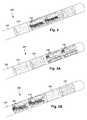
- FIG. 3Ais a perspective view of a third embodiment of a portion of a lead having a plurality of segmented electrodes, according to the invention.
- FIG. 3Bis a perspective view of a fourth embodiment of a portion of a lead having a plurality of segmented electrodes, according to the invention.
- FIG. 4is a schematic diagram of radial current steering along various electrode levels along the length of a lead, according to the invention.
- FIG. 5is a perspective view of another embodiment of a portion of a lead having a plurality of segmented electrodes arranged in a staggered orientation, according to the invention.
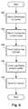
- FIG. 6is a flowchart of one embodiment of a method of making a lead, according to the invention.
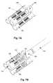
- FIG. 7Ais a schematic perspective view of one embodiment of electrodes disposed on a carrier, according to the invention.
- FIG. 7Bis a schematic perspective view of conductors attached to the electrodes of FIG. 7A , according to the invention.
- FIG. 7Cis a schematic perspective view of the carrier and electrodes of FIG. 7B wrapped into a cylinder, according to the invention.
- FIG. 7Dis a schematic perspective view of steps in the molding of a lead body around the carrier and electrodes of FIG. 7C , according to the invention.
- FIG. 7Eis a schematic perspective view of a distal portion of a lead formed by the procedure illustrated in FIGS. 7A-7D , according to the invention.
- FIG. 8is a schematic perspective view of a segmented electrode, according to the invention.
- FIG. 9Ais a schematic perspective view of another embodiment of electrodes disposed on a carrier, according to the invention.
- FIG. 9Bis a schematic perspective view of conductors attached to the electrodes of FIG. 9A , according to the invention.
- the inventionis directed to the area of electrical stimulation systems and methods of making and using the systems.
- the present inventionis also directed to forming electrical stimulation leads with multiple sets of radially-aligned segmented electrodes, as well as methods of making and using the segmented electrodes, leads, and electrical stimulation systems.
- a lead for deep brain stimulationmay include stimulation electrodes, recording electrodes, or a combination of both.
- a practitionermay determine the position of the target neurons using the recording electrode(s) and then position the stimulation electrode(s) accordingly without removal of a recording lead and insertion of a stimulation lead.
- the same electrodescan be used for both recording and stimulation.
- separate leadscan be used; one with recording electrodes which identify target neurons, and a second lead with stimulation electrodes that replaces the first after target neuron identification.
- a leadmay include recording electrodes spaced around the circumference of the lead to more precisely determine the position of the target neurons.
- the leadis rotatable so that the stimulation electrodes can be aligned with the target neurons after the neurons have been located using the recording electrodes.
- the leadsare described herein relative to use for deep brain stimulation, but it will be understood that any of the leads can be used for applications other than deep brain stimulation.
- Deep brain stimulation devices and leadsare described in, for example, U.S. Patent Application Publication No. 2006/0149335 A1 (“Devices and Methods For Brain Stimulation”), U.S. patent application Ser. No. 12/237,888 (“Leads With Non-Circular-Shaped Distal Ends For Brain Stimulation Systems and Methods of Making and Using”), U.S. Patent Application Publication 2007/0150036 A1 (“Stimulator Leads and Methods For Lead Fabrication”), U.S. patent application Ser. No. 12/177,823 (“Lead With Transition and Methods of Manufacture and Use”), U.S. patent application Ser. No.
- FIG. 1illustrates one embodiment of a device 100 for brain stimulation.
- the deviceincludes a lead 110 , a plurality of electrodes 125 disposed at least partially about a circumference of the lead 110 , a plurality of terminals 135 , a connector 130 for connection of the electrodes to a control unit, and a stylet 140 for assisting in insertion and positioning of the lead in the patient's brain.
- the stylet 140can be made of a rigid material. Examples of suitable materials for the stylet include, but are not limited to, tungsten, stainless steel, and rigid plastic.
- the stylet 140may have a handle 150 to assist insertion into the lead 110 , as well as rotation of the stylet 140 and lead 110 .
- the connector 130fits over a proximal end of the lead 110 , preferably after removal of the stylet 140 .
- the control unit(not shown) is typically an implantable pulse generator that can be implanted into a patient's body, for example, below the patient's clavicle area.
- the pulse generatorcan have eight stimulation channels which may be independently programmable to control the magnitude of the current stimulus from each channel. In some cases the pulse generator may have more than eight stimulation channels (e.g., 16-, 32-, or more stimulation channels).
- the control unitmay have one, two, three, four, or more connector ports, for receiving the plurality of terminals 135 at the proximal end of the lead 110 .
- access to the desired position in the braincan be accomplished by drilling a hole in the patient's skull or cranium with a cranial drill (commonly referred to as a burr), and coagulating and incising the dura mater, or brain covering.
- the lead 110can be inserted into the cranium and brain tissue with the assistance of the stylet 140 .
- the lead 110can be guided to the target location within the brain using, for example, a stereotactic frame and a microdrive motor system.
- the microdrive motor systemcan be fully or partially automatic.
- the microdrive motor systemmay be configured to perform one or more the following actions (alone or in combination): insert the lead 110 , retract the lead 110 , or rotate the lead 110 .
- measurement devices coupled to the muscles or other tissues stimulated by the target neurons, or a unit responsive to the patient or cliniciancan be coupled to the control unit or microdrive motor system.
- the measurement device, user, or cliniciancan indicate a response by the target muscles or other tissues to the stimulation or recording electrode(s) to further identify the target neurons and facilitate positioning of the stimulation electrode(s).
- a measurement devicecan be used to observe the muscle and indicate changes in tremor frequency or amplitude in response to stimulation of neurons.
- the patient or clinicianmay observe the muscle and provide feedback.
- the lead 110 for deep brain stimulationcan include stimulation electrodes, recording electrodes, or both.
- the lead 110is rotatable so that the stimulation electrodes can be aligned with the target neurons after the neurons have been located using the recording electrodes.
- Stimulation electrodesmay be disposed on the circumference of the lead 110 to stimulate the target neurons. Stimulation electrodes may be ring-shaped so that current projects from each electrode equally in every direction from the position of the electrode along a length of the lead 110 . Ring electrodes, however, typically do not enable stimulus current to be directed to only one side of the lead. Segmented electrodes, however, can be used to direct stimulus current to one side, or even a portion of one side, of the lead. When segmented electrodes are used in conjunction with an implantable pulse generator that delivers constant current stimulus, current steering can be achieved to more precisely deliver the stimulus to a position around an axis of the lead (i.e., radial positioning around the axis of the lead).
- segmented electrodescan be utilized in addition to, or as an alternative to, ring electrodes. Though the following description discusses stimulation electrodes, it will be understood that all configurations of the stimulation electrodes discussed may be utilized in arranging recording electrodes as well.
- FIG. 2illustrates one embodiment of a distal portion of a lead 200 for brain stimulation.
- the lead 200includes a lead body 210 , one or more optional ring electrodes 220 , and a plurality of sets of segmented electrodes 230 .
- the lead body 210can be formed of a biocompatible, non-conducting material such as, for example, a polymeric material. Suitable polymeric materials include, but are not limited to, silicone, polyurethane, polyurea, polyurethane-urea, polyethylene, or the like.
- the lead 200Once implanted in the body, the lead 200 may be in contact with body tissue for extended periods of time.
- the lead 200has a cross-sectional diameter of no more than 1.5 mm and may be in the range of 1 to 1.5 mm. In at least some embodiments, the lead 200 has a length of at least 10 cm and the length of the lead 200 may be in the range of 25 to 70 cm.
- the electrodesmay be made using a metal, alloy, conductive oxide, or any other suitable conductive biocompatible material.
- suitable materialsinclude, but are not limited to, platinum, platinum iridium alloy, iridium, titanium, tungsten, palladium, or the like.
- the electrodesare made of a material that is biocompatible and does not substantially corrode under expected operating conditions in the operating environment for the expected duration of use.
- Each of the electrodescan either be used or unused (OFF).
- the electrodecan be used as an anode or cathode and carry anodic or cathodic current.
- an electrodemight be an anode for a period of time and a cathode for a period of time.
- Stimulation electrodes in the form of ring electrodes 220may be disposed on any part of the lead body 210 , usually near a distal end of the lead 200 .
- the lead 200includes two ring electrodes 220 .
- Any number of ring electrodes 220may be disposed along the length of the lead body 210 including, for example, one, two three, four, five, six, seven, eight, nine, ten, eleven, twelve, thirteen, fourteen, fifteen, sixteen or more ring electrodes 220 . It will be understood that any number of ring electrodes may be disposed along the length of the lead body 210 .
- the ring electrodes 220are substantially cylindrical and wrap around the entire circumference of the lead body 210 .
- the outer diameters of the ring electrodes 220are substantially equal to the outer diameter of the lead body 210 .
- the length of the ring electrodes 220may vary according to the desired treatment and the location of the target neurons. In some embodiments the length of the ring electrodes 220 are less than or equal to the diameters of the ring electrodes 220 . In other embodiments, the lengths of the ring electrodes 220 are greater than the diameters of the ring electrodes 220 .
- Deep brain stimulation leadsmay include one or more sets of segmented electrodes. Segmented electrodes may provide for superior current steering than ring electrodes because target structures in deep brain stimulation are not typically symmetric about the axis of the distal electrode array. Instead, a target may be located on one side of a plane running through the axis of the lead.
- RSEAradially segmented electrode array
- the lead 200is shown having a plurality of segmented electrodes 230 .
- Any number of segmented electrodes 230may be disposed on the lead body 210 including, for example, one, two three, four, five, six, seven, eight, nine, ten, eleven, twelve, thirteen, fourteen, fifteen, sixteen or more segmented electrodes 230 . It will be understood that any number of segmented electrodes 230 may be disposed along the length of the lead body 210 .
- the segmented electrodes 230may be grouped into sets of segmented electrodes, where each set is disposed around a circumference of the lead 200 at a particular longitudinal portion of the lead 200 .
- the lead 200may have any number segmented electrodes 230 in a given set of segmented electrodes.
- the lead 200may have one, two, three, four, five, six, seven, eight, or more segmented electrodes 230 in a given set.
- each set of segmented electrodes 230 of the lead 200contains the same number of segmented electrodes 230 .
- the segmented electrodes 230 disposed on the lead 200may include a different number of electrodes than at least one other set of segmented electrodes 230 disposed on the lead 200 .
- the segmented electrodes 230may vary in size and shape. In some embodiments, the segmented electrodes 230 are all of the same size, shape, diameter, width or area or any combination thereof. In some embodiments, the segmented electrodes 230 of each circumferential set (or even all segmented electrodes disposed on the lead 200 ) may be identical in size and shape.
- Each set of segmented electrodes 230may be disposed around the circumference of the lead body 210 to form a substantially cylindrical shape around the lead body 210 .
- the spacing between individual electrodes of a given set of the segmented electrodesmay be the same, or different from, the spacing between individual electrodes of another set of segmented electrodes on the lead 200 .
- equal spaces, gaps or cutoutsare disposed between each segmented electrode 230 around the circumference of the lead body 210 .
- the spaces, gaps or cutouts between the segmented electrodes 230may differ in size or shape.
- the spaces, gaps, or cutouts between segmented electrodes 230may be uniform for a particular set of the segmented electrodes 230 , or for all sets of the segmented electrodes 230 .
- the sets of segmented electrodes 230may be positioned in irregular or regular intervals along a length the lead body 210 .
- Conductors that attach to the ring electrodes 220 or segmented electrodes 230extend along the lead body 210 . These conductors may extend through the material of the lead 200 or along one or more lumens defined by the lead 200 , or both. The conductors are presented at a connector (via terminals) for coupling of the electrodes 220 , 230 to a control unit (not shown).
- the ring electrodes 220 and the segmented electrodes 230may be arranged in any suitable configuration.
- the ring electrodes 220can flank the two sets of segmented electrodes 230 (see e.g., FIG. 2 ).
- the two sets of ring electrodes 220can be disposed proximal to the two sets of segmented electrodes 230 (see e.g., FIG.
- the two sets of ring electrodes 220can be disposed distal to the two sets of segmented electrodes 230 (see e.g., FIG. 3B ). It will be understood that other configurations are possible as well (e.g., alternating ring and segmented electrodes, or the like).
- the electrode arrangement of FIG. 3Amay be useful if the physician anticipates that the neural target will be closer to a distal tip of the lead body 210
- the electrode arrangement of FIG. 3Bmay be useful if the physician anticipates that the neural target will be closer to a proximal end of the lead body 210 .
- any combination of ring electrodes 220 and segmented electrodes 230may be disposed on the lead 200 .
- the leadmay include a first ring electrode, two sets of segmented electrodes, each set formed of three segmented electrodes 230 , and a final ring electrode at the end of the lead.
- This configurationmay simply be referred to as a 1-3-3-1 configuration. It may be useful to refer to the electrodes with this shorthand notation.
- the embodiment of FIG. 3Amay be referred to as a 3-3-1-1 configuration
- the embodiment of FIG. 3Bmay be referred to as a 1-1-3-3 configuration.
- Other eight-electrode configurationsinclude, for example, a 2-2-2-2 configuration, where four sets of segmented electrodes are disposed on the lead, and a 4-4 configuration, where two sets of segmented electrodes, each having four segmented electrodes 230 are disposed on the lead.
- the leadincludes 16 electrodes. Possible configurations for a 16-electrode lead include, but are not limited to 4-4-4-4; 8-8; 3-3-3-3-3-1 (and all rearrangements of this configuration); and 2-2-2-2-2-2-2-2-2-2.
- FIG. 4is a schematic diagram to illustrate radial current steering along various electrode levels along the length of the lead 200 . While conventional lead configurations with ring electrodes are only able to steer current along the length of the lead (the z-axis), the segmented electrode configuration is capable of steering current in the x-axis, y-axis as well as the z-axis. Thus, the centroid of stimulation may be steered in any direction in the three-dimensional space surrounding the lead 200 . In some embodiments, the radial distance, r, and the angle ⁇ around the circumference of the lead 200 may be dictated by the percentage of anodic current (recognizing that stimulation predominantly occurs near the cathode, although strong anodes may cause stimulation as well) introduced to each electrode. In at least some embodiments, the configuration of anodes and cathodes along the segmented electrodes allows the centroid of stimulation to be shifted to a variety of different locations along the lead 200 .
- the centroid of stimulationcan be shifted at each level along the length of the lead 200 .
- the use of multiple sets of segmented electrodes at different levels along the length of the leadallows for three-dimensional current steering.
- the sets of segmented electrodesare shifted collectively (i.e., the centroid of simulation is similar at each level along the length of the lead).
- each set of segmented electrodesis controlled independently.
- Each set of segmented electrodesmay contain two, three, four, five, six, seven, eight or more segmented electrodes. It will be understood that different stimulation profiles may be produced by varying the number of segmented electrodes at each level.
- each set of segmented electrodesincludes only two segmented electrodes, uniformly distributed gaps (inability to stimulate selectively) may be formed in the stimulation profile.
- at least three segmented electrodes 230 in a setare utilized to allow for true 360° selectivity.
- measurement devices coupled to the muscles or other tissues stimulated by the target neurons or a unit responsive to the patient or cliniciancan be coupled to the control unit or microdrive motor system.
- the measurement device, user, or cliniciancan indicate a response by the target muscles or other tissues to the stimulation or recording electrodes to further identify the target neurons and facilitate positioning of the stimulation electrodes.
- a measurement devicecan be used to observe the muscle and indicate changes in tremor frequency or amplitude in response to stimulation of neurons.
- the patient or clinicianmay observe the muscle and provide feedback.
- the lead 200When the lead 200 includes a plurality of sets of segmented electrodes 230 , it may be desirable to form the lead 200 such that corresponding electrodes of different sets of segmented electrodes 230 are radially aligned with one another along the length of the lead 200 (see e.g., the segmented electrodes 230 shown in FIG. 2 ). Radial alignment between corresponding electrodes of different sets of segmented electrodes 230 along the length of the lead 200 may reduce uncertainty as to the location or orientation between corresponding segmented electrodes of different sets of segmented electrodes.
- electrode arrayssuch that corresponding electrodes of different sets of segmented electrodes along the length of the lead 200 are radially aligned with one another and do not radially shift in relation to one another during manufacturing of the lead 200 .
- FIG. 5is a side view of another embodiment of the lead 200 having a plurality of sets of segmented electrodes. As shown in FIG. 5 , individual electrodes in the two sets of segmented electrodes 230 are staggered relative to one another along the length of the lead body 210 . In some cases, the staggered positioning of corresponding electrodes of different sets of segmented electrodes along the length of the lead 200 may be designed for a specific application.
- Corresponding electrodes of at least two different sets of segmented electrodescan be radially aligned with one another along the length of the lead by disposing tabs on at least some of the electrodes and stringing an elongated member (e.g., one or more conductors, or the like) through one or more guides formed in one or more of the tabs disposed along different sets of the segmented electrodes.
- Corresponding electrodes of different sets of segmented electrodescan be radially aligned with one another along the length of the lead by disposing one or more electrode on membranes configured and arranged to couple to the lead. It will be understood that radially-aligning segmented electrodes along the length of the lead can be applied to either all, or only some, of the total number of segmented electrodes disposed on the lead.
- FIG. 6is a flowchart describing an embodiment of a method of making a lead with segmented electrodes.
- multiple electrodes 702 , 704are attached to a carrier 706 , as illustrated, for example, in FIG. 7A .
- multiple segmented electrodes 702are attached to the carrier in an arrangement that, when the carrier is formed into a cylinder, result in the segmented electrodes being positioned in the desired arrangement (e.g., as one or more sets of segmented electrodes as illustrated, for example, in FIGS. 2 , 3 A, 3 B, and 5 ) on the lead.
- the segmented electrodes 702can be formed in any suitable shape or size and can be formed of the materials described above.
- the segmented electrodeshave a curved shape.
- the curved shapepreferably corresponds to the curvature of the lead.
- the curved shape of the segmented electrodescan have an arc of at least 10, 15, 20, 30, 40, 50, or 60 degrees.
- the arc of the segmented electrodemay be no more than 345, 330, 320, 300, 270, 180, or 175 degrees.
- the arc of the segmented electrodesis in the range of 10 to 345 degrees or in the range of 30 to 300 degrees or in the range of 50 to 180 degrees or in the range of 15 to 175 degrees.
- the segmented electrodes 702optionally include one or more additional features to aid in holding the segmented electrode within the lead.
- One embodiment of a segmented electrode 702 displaying several optional featuresis provided in FIG. 8 .
- the segmented electrodeincludes a stimulation surface 804 that, when the lead is formed and inserted into the patient, will be exposed to patient tissue.
- the segmented electrodealso includes an interior surface 806 opposing the stimulation surface 804 .
- the interior surface 806will be in the interior the lead.
- One optional feature that aids in anchoring the segmented electrode 702 within the leadis a corrugated, or otherwise rough or non-uniform, texture 808 of the interior surface 806 .
- the non-uniform texture 808 of the interior surface 806increases the surface area that contacts the material of the lead body that is formed around the segmented electrode 702 , as described below, and helps in retaining the segmented electrode within the lead.
- the corrugation of the texture 808can have a triangular cross-section, as illustrated in FIG. 8 , or any other suitable shape including, but not limited, a square, rectangular, trapezoidal, hemispherical, hexagonal, or any other regular or irregular cross-section.
- suitable non-uniform texturesinclude, but are not limited to, a checkerboard arrangement that is similar to corrugation but with intersecting grooves, an arrangement with multiple cleat-like projections or dimples extending from the surface 806 , or a surface with a texture formed by knurling, grit blasting, or other methods of roughening of the surface, and the like.
- the anchoring tabs 810are arranged so that they project into the interior of the lead and into the material of the lead body that is formed around the segmented electrode.
- the anchoring tabscan have any suitable size or shape and may optionally include one or more holes 812 in the tabs. In at least some embodiments, material from the lead body may flow into the holes 812 during the molding process to provide additional anchoring.
- the anchoring tabsmay be arranged around the segmented electrode in any suitable arrangement. For example, as illustrated in FIG. 8 , two anchoring tabs 810 may extend from opposing sides towards each other.
- the two anchoring tabsmay extend from only a portion of a particular side of the segmented electrode 702 .
- two anchoring tabsmay extend from the segmented electrode 702 with one tab extending near one end of a side of the electrode and the other tab extending near the other end of the opposing side of the electrode so that the two tabs are diagonally opposed. It will be understood that other arrangements can be used including, for example, arrangements in which tabs are directly opposed.
- one or more ring electrodes 704may be used. These ring electrodes can be positioned at the ends of the carrier, as illustrated in FIG. 7A , or between sets of segmented electrodes, or any combination thereof. It will be recognized that some embodiments may not include ring electrodes (including, for example, the embodiment of FIGS. 9A and 9B described further below.)
- the carrier 706is a temporary structure to which the electrodes 702 , 704 are attached for manufacture of the lead.
- the carrieris typically relatively thin and can be made of any suitable material that is sufficiently flexible to be formed into a cylinder as described below.
- suitable materialsinclude, but are not limited to, metals (e.g., iron, aluminum, and the like), alloys (e.g., MP35N, steel, stainless steel, and the like), and plastics (e.g., plastic films such as those used for flexible circuits such as polyimide, polyetheretherketone (PEEK), polyetherimide, polyethylene naphthalate, polyethylene terephthalate, other polyesters, fluoropolymers, and the like).
- PEEKpolyetheretherketone
- the carriermay be flat (see, e.g., FIG. 9A ) or the carrier may be formed into one or more curved sections (see, e.g., FIGS. 7A and 7B ) in anticipation of forming a cylinder, as described below.
- the electrodes 702 , 704can be attached to the carrier 706 by any suitable method including, but not limited to, welding, soldering, mounting using an adhesive (e.g., an epoxy), and the like. It will be understood that selection of a carrier material may limit the method of attachment of the electrodes to the carrier or selection of the method of attachment may limit the carrier material that can be used. Preferably, the carrier material (and any supplemental material, such as a solder or adhesive used to attach the electrodes to the carrier) is biocompatible as small amounts of such materials may remain on the finished lead.
- the carrier 706may include one or more features, such as slots 708 and tabs (see FIG. 9A for tabs 910 ), to facilitate formation of the carrier into a cylinder, as described below.
- Such featuresmay act, for example, as tooling aids or registration aids or a combination thereof
- conductors 712are attached to the electrodes 702 , 704 (step 604 of FIG. 6 ) as illustrated, for example, in FIG. 7B .
- the conductors 712can be, for example, insulated wires with a portion of the insulation removed to make contact with the electrodes 702 , 704 .
- a different conductor 712can be attached to each electrode 702 , 704 , as illustrated in FIG. 7B . In other embodiments, the same conductor may be attached to two or more of the electrodes.
- the conductors 712can be attached by any suitable method including, but not limited to, welding, soldering, crimping, using a conductive adhesive, and the like.
- the conductors 712can be attached to any suitable part of the electrodes 702 , 704 .
- the conductors 712can be attached to the interior surface or tabs of a segmented electrode 702 or the conductors 712 can be attached to an interior surface of the ring electrodes 704 .
- the ring electrode 704may include a notch 714 to facilitate attachment of the conductor 712 .
- the conductors 712are typically attached to terminals (not shown) disposed at a proximal end of the lead. A portion of the conductors proximal to the electrodes may be disposed in a sleeve 716 that can be formed of a polymer material.
- the sleevemay form part of the lead body.
- the sleeve 716defines a central lumen (not shown) and one or more outer lumens (not shown) that carry the conductors 712 .
- the central lumenmay accommodate a stylet.
- the carrier 706is formed into a cylinder, as illustrated, for example, in FIG. 7C .
- the carrier 706with the electrodes 702 , 704 disposed thereon, is wrapped around a mandrel 718 to facilitate formation of the cylinder.
- the mandrel 718may also be partially inserted into the sleeve 716 (e.g., into the central lumen of the sleeve) as illustrated in FIG. 7C .
- FIG. 7Cshows a cylinder with a circular cross-section
- other types of hollow rodscan be formed including, but not limited to, hollow rods with square, rectangular, oval, triangular, hexagonal, or octagonal cross-sections.
- the carriercan be held in the cylindrical form by any suitable method.
- a forming tool that rolls the carrier into a cylinderfacilitates maintenance of the cylindrical shape.
- straps or fastenersmay be attached to the carrier, or wrapped around the carrier, to hold it in the cylindrical form.
- two or more portions of the carriere.g., tabs 910 ( FIG. 9A ) and the corresponding opposing portion of the carrier
- the carriermaintains its shape once formed into the shape.
- a lead body 720is formed around the carrier 706 and electrodes 702 , 704 (step 608 ).
- FIG. 7EOne example of the formation of the lead body 720 ( FIG. 7E ) is illustrated in FIG. 7D .
- the carrier 706 and the associated electrodes 702 , 704are disposed in a mold (only the bottom portion 722 of which is shown in FIG. 7D for ease of illustration).
- the mandrel 718may remain in the assembly to maintain a central lumen within the lead.
- a central lumenmay be useful for receiving a stylet to aid in implantation or positioning of the lead.
- plastic materialis introduced into the mold to form the lead body 720 .
- Any suitable molding techniquecan be used including, but not limited to, injection molding (e.g., rotary injection molding) and compression molding.
- the plastic material of the lead body 720may cover all or a portion of the carrier 706 or, alternatively, may cover none of the carrier.
- the lead body 720may cover all or a portion of the sleeve 716 that covers the conductors 712 .
- the conductorsmay not be disposed in a sleeve and the lead body is molded around the conductors as well as the carrier 706 and electrodes 702 , 704 .
- the material of the lead bodyis introduced beneath the carrier and is disposed around the electrodes 702 , 704 so that at least the interior surfaces of the electrodes 702 , 704 is in contact with the material of the lead body and the tabs, if any, extend into the material of the lead body.
- Suitable materials for the lead bodyinclude biocompatible polymer materials, such as silicone, polyurethane, polyethylene, polyurea, polyurethane-urea, polyetheretherketone, and the like.
- the material introduced into the moldmay be a polymer itself (for example, a polymer that has been heated to a fluid or semi-fluid state) or the material may be a pre-polymer material (e.g., monomers or oligomers) that is polymerized during the molding process.
- the assemblycan be removed from the mold, as illustrated in FIG. 7D .
- the carrier 706is removed leaving the electrodes 702 , 704 disposed in the lead body, as illustrated, for example, in FIG. 7E .
- the carrier 706can be removed by any suitable method such as, for example, grinding (e.g., centerless grinding), etching, cutting, degrading an adhesive to release the carrier, laser ablation, and the like. Suitable methods for removal of the carrier 706 may depend on the materials of the carrier and other components of the lead (for example, the electrodes 702 , 704 and the lead body 720 ). In some embodiments, removal of the carrier 706 may also include removal of a small portion from the exposed surface of the electrodes 702 , 704 to facilitate complete or nearly complete removal of the carrier. Alternatively, a portion of the carrier may be left on one or more of the electrodes.
- the mandrel 718is removed prior to or after removal of the carrier.
- the removal of the mandrelleaves a central lumen.
- a plug 724 of polymer (or other) materialmay be inserted into the distal end of the central lumen to close the lumen and prevent ingress of body fluids into the lumen when the lead is implanted.
- the plugmay be reflowed by heating, or adhesive can be used, to secure the plug in the lead body.
- FIGS. 9A and 9Billustrate another arrangement of electrodes.
- FIG. 9Aillustrates a carrier 906 with only segmented electrodes 902 a , 902 b disposed on the carrier.
- segmented electrodes 902 aform two groups of three circumferentially distributed electrodes and segmented electrodes 902 b form two groups of two circumferentially distributed electrodes.
- the distal end of the final leadis illustrated in FIG. 9B .
- each of the electrodescould be attached to a different conductor and associated terminal, in at least some embodiments, two or more of the electrodes are attached electrically coupled to the same conductor.
- the group of two electrodes 902 b at the distal endcan be electrically coupled to the same conductor (e.g., both directly attached to the same conductor or one attached to the conductor and a separate wire bridging the two electrodes).
- the group of two electrodes 902 b at the proximal endcan be electrically coupled to another one of the conductors. Examples of alternative electrode arrangements are discussed in U.S. patent application Ser. No. 12/761,622, incorporated herein by reference.
Landscapes
- Health & Medical Sciences (AREA)
- Neurology (AREA)
- Neurosurgery (AREA)
- Psychology (AREA)
- Cardiology (AREA)
- Heart & Thoracic Surgery (AREA)
- Engineering & Computer Science (AREA)
- Biomedical Technology (AREA)
- Nuclear Medicine, Radiotherapy & Molecular Imaging (AREA)
- Radiology & Medical Imaging (AREA)
- Life Sciences & Earth Sciences (AREA)
- Animal Behavior & Ethology (AREA)
- General Health & Medical Sciences (AREA)
- Public Health (AREA)
- Veterinary Medicine (AREA)
- Electrotherapy Devices (AREA)
Abstract
Description
This application is a continuation-in-part of U.S. patent application Ser. No. 12/498,650, filed Jul. 7, 2009; the entire contents of which are incorporated herein by reference.
The invention is directed to the area of electrical stimulation systems and methods of making and using the systems. The present invention is also directed to electrical stimulation leads with multiple sets of radially-aligned segmented electrodes, as well as methods of making and using the segmented electrodes, leads, and electrical stimulation systems.
Electrical stimulation can be useful for treating a variety of conditions. Deep brain stimulation can be useful for treating, for example, Parkinson's disease, dystonia, essential tremor, chronic pain, Huntington's Disease, levodopa-induced dyskinesias and rigidity, bradykinesia, epilepsy and seizures, eating disorders, and mood disorders. Typically, a lead with a stimulating electrode at or near a tip of the lead provides the stimulation to target neurons in the brain. Magnetic resonance imaging (“MRI”) or computerized tomography (“CT”) scans can provide a starting point for determining where the stimulating electrode should be positioned to provide the desired stimulus to the target neurons.
After the lead is implanted into a patient's brain, electrical stimulus current can be delivered through selected electrodes on the lead to stimulate target neurons in the brain. Typically, the electrodes are formed into rings disposed on a distal portion of the lead. The stimulus current projects from the ring electrodes equally in every direction. Because of the ring shape of these electrodes, the stimulus current cannot be directed to one or more specific positions around the ring electrode (e.g., on one or more sides, or points, around the lead). Consequently, undirected stimulation may result in unwanted stimulation of neighboring neural tissue, potentially resulting in undesired side effects.
One embodiment is a method of making a stimulation lead that includes attaching multiple segmented electrodes to a carrier. Each of the segmented electrodes has a curved form extending over an arc in the range of 10 to 345 degrees. The method further includes attaching conductors to the segmented electrodes; forming the carrier into a cylinder with segmented electrodes disposed within the cylinder; molding a lead body around the segmented electrodes disposed on the carrier; and removing at least a portion of the carrier to separate the segmented electrodes.
Another embodiment is a method of making a stimulation lead that includes attaching multiple segmented electrodes to a carrier; attaching conductors to the segmented electrodes; forming the carrier into a cylinder with the segmented electrodes disposed within the cylinder; molding a lead body around the plurality of segmented electrodes disposed on the carrier; and grinding at least a portion of the carrier away to separate the segmented electrodes.
Yet another embodiment is a method of making a stimulation lead that includes attaching multiple segmented electrodes to a carrier. Each of the segmented electrodes comprises a corrugated interior surface. The method further includes attaching conductors to the segmented electrodes; forming the carrier into a cylinder with the segmented electrodes disposed within the cylinder; molding a lead body around the segmented electrodes disposed on the carrier; and removing at least a portion of the carrier to separate the segmented electrodes.
Non-limiting and non-exhaustive embodiments of the present invention are described with reference to the following drawings. In the drawings, like reference numerals refer to like parts throughout the various figures unless otherwise specified.
For a better understanding of the present invention, reference will be made to the following Detailed Description, which is to be read in association with the accompanying drawings, wherein:
The invention is directed to the area of electrical stimulation systems and methods of making and using the systems. The present invention is also directed to forming electrical stimulation leads with multiple sets of radially-aligned segmented electrodes, as well as methods of making and using the segmented electrodes, leads, and electrical stimulation systems.
A lead for deep brain stimulation may include stimulation electrodes, recording electrodes, or a combination of both. A practitioner may determine the position of the target neurons using the recording electrode(s) and then position the stimulation electrode(s) accordingly without removal of a recording lead and insertion of a stimulation lead. In some embodiments, the same electrodes can be used for both recording and stimulation. In some embodiments, separate leads can be used; one with recording electrodes which identify target neurons, and a second lead with stimulation electrodes that replaces the first after target neuron identification. A lead may include recording electrodes spaced around the circumference of the lead to more precisely determine the position of the target neurons. In at least some embodiments, the lead is rotatable so that the stimulation electrodes can be aligned with the target neurons after the neurons have been located using the recording electrodes. For illustrative purposes, the leads are described herein relative to use for deep brain stimulation, but it will be understood that any of the leads can be used for applications other than deep brain stimulation.
Deep brain stimulation devices and leads are described in, for example, U.S. Patent Application Publication No. 2006/0149335 A1 (“Devices and Methods For Brain Stimulation”), U.S. patent application Ser. No. 12/237,888 (“Leads With Non-Circular-Shaped Distal Ends For Brain Stimulation Systems and Methods of Making and Using”), U.S. Patent Application Publication 2007/0150036 A1 (“Stimulator Leads and Methods For Lead Fabrication”), U.S. patent application Ser. No. 12/177,823 (“Lead With Transition and Methods of Manufacture and Use”), U.S. patent application Ser. No. 12/427,935 (“Electrodes For Stimulation Leads and Methods of Manufacture and Use”), U.S. patent application Ser. No. 61/170,037 (“Deep Brain Stimulation Current Steering with Split Electrodes”), U.S. patent application Ser. No. 61/022,953, U.S. patent application Ser. No. 61/316,759, and U.S. patent application Ser. No. 12/356,480. Each of these references is incorporated herein by reference.
The control unit (not shown) is typically an implantable pulse generator that can be implanted into a patient's body, for example, below the patient's clavicle area. The pulse generator can have eight stimulation channels which may be independently programmable to control the magnitude of the current stimulus from each channel. In some cases the pulse generator may have more than eight stimulation channels (e.g., 16-, 32-, or more stimulation channels). The control unit may have one, two, three, four, or more connector ports, for receiving the plurality ofterminals 135 at the proximal end of thelead 110.
In one example of operation, access to the desired position in the brain can be accomplished by drilling a hole in the patient's skull or cranium with a cranial drill (commonly referred to as a burr), and coagulating and incising the dura mater, or brain covering. Thelead 110 can be inserted into the cranium and brain tissue with the assistance of thestylet 140. Thelead 110 can be guided to the target location within the brain using, for example, a stereotactic frame and a microdrive motor system. In some embodiments, the microdrive motor system can be fully or partially automatic. The microdrive motor system may be configured to perform one or more the following actions (alone or in combination): insert thelead 110, retract thelead 110, or rotate thelead 110.
In some embodiments, measurement devices coupled to the muscles or other tissues stimulated by the target neurons, or a unit responsive to the patient or clinician, can be coupled to the control unit or microdrive motor system. The measurement device, user, or clinician can indicate a response by the target muscles or other tissues to the stimulation or recording electrode(s) to further identify the target neurons and facilitate positioning of the stimulation electrode(s). For example, if the target neurons are directed to a muscle experiencing tremors, a measurement device can be used to observe the muscle and indicate changes in tremor frequency or amplitude in response to stimulation of neurons. Alternatively, the patient or clinician may observe the muscle and provide feedback.
Thelead 110 for deep brain stimulation can include stimulation electrodes, recording electrodes, or both. In at least some embodiments, thelead 110 is rotatable so that the stimulation electrodes can be aligned with the target neurons after the neurons have been located using the recording electrodes.
Stimulation electrodes may be disposed on the circumference of thelead 110 to stimulate the target neurons. Stimulation electrodes may be ring-shaped so that current projects from each electrode equally in every direction from the position of the electrode along a length of thelead 110. Ring electrodes, however, typically do not enable stimulus current to be directed to only one side of the lead. Segmented electrodes, however, can be used to direct stimulus current to one side, or even a portion of one side, of the lead. When segmented electrodes are used in conjunction with an implantable pulse generator that delivers constant current stimulus, current steering can be achieved to more precisely deliver the stimulus to a position around an axis of the lead (i.e., radial positioning around the axis of the lead).
To achieve current steering, segmented electrodes can be utilized in addition to, or as an alternative to, ring electrodes. Though the following description discusses stimulation electrodes, it will be understood that all configurations of the stimulation electrodes discussed may be utilized in arranging recording electrodes as well.
The electrodes may be made using a metal, alloy, conductive oxide, or any other suitable conductive biocompatible material. Examples of suitable materials include, but are not limited to, platinum, platinum iridium alloy, iridium, titanium, tungsten, palladium, or the like. Preferably, the electrodes are made of a material that is biocompatible and does not substantially corrode under expected operating conditions in the operating environment for the expected duration of use.
Each of the electrodes can either be used or unused (OFF). When the electrode is used, the electrode can be used as an anode or cathode and carry anodic or cathodic current. In some instances, an electrode might be an anode for a period of time and a cathode for a period of time.
Stimulation electrodes in the form ofring electrodes 220 may be disposed on any part of thelead body 210, usually near a distal end of thelead 200. InFIG. 2 , thelead 200 includes tworing electrodes 220. Any number ofring electrodes 220 may be disposed along the length of thelead body 210 including, for example, one, two three, four, five, six, seven, eight, nine, ten, eleven, twelve, thirteen, fourteen, fifteen, sixteen ormore ring electrodes 220. It will be understood that any number of ring electrodes may be disposed along the length of thelead body 210. In some embodiments, thering electrodes 220 are substantially cylindrical and wrap around the entire circumference of thelead body 210. In some embodiments, the outer diameters of thering electrodes 220 are substantially equal to the outer diameter of thelead body 210. The length of thering electrodes 220 may vary according to the desired treatment and the location of the target neurons. In some embodiments the length of thering electrodes 220 are less than or equal to the diameters of thering electrodes 220. In other embodiments, the lengths of thering electrodes 220 are greater than the diameters of thering electrodes 220.
Deep brain stimulation leads may include one or more sets of segmented electrodes. Segmented electrodes may provide for superior current steering than ring electrodes because target structures in deep brain stimulation are not typically symmetric about the axis of the distal electrode array. Instead, a target may be located on one side of a plane running through the axis of the lead. Through the use of a radially segmented electrode array (“RSEA”), current steering can be performed not only along a length of the lead but also around a circumference of the lead. This provides precise three-dimensional targeting and delivery of the current stimulus to neural target tissue, while potentially avoiding stimulation of other tissue.
InFIG. 2 , thelead 200 is shown having a plurality ofsegmented electrodes 230. Any number ofsegmented electrodes 230 may be disposed on thelead body 210 including, for example, one, two three, four, five, six, seven, eight, nine, ten, eleven, twelve, thirteen, fourteen, fifteen, sixteen or moresegmented electrodes 230. It will be understood that any number ofsegmented electrodes 230 may be disposed along the length of thelead body 210.
Thesegmented electrodes 230 may be grouped into sets of segmented electrodes, where each set is disposed around a circumference of thelead 200 at a particular longitudinal portion of thelead 200. Thelead 200 may have any number segmentedelectrodes 230 in a given set of segmented electrodes. Thelead 200 may have one, two, three, four, five, six, seven, eight, or moresegmented electrodes 230 in a given set. In at least some embodiments, each set ofsegmented electrodes 230 of thelead 200 contains the same number ofsegmented electrodes 230. Thesegmented electrodes 230 disposed on thelead 200 may include a different number of electrodes than at least one other set ofsegmented electrodes 230 disposed on thelead 200.
Thesegmented electrodes 230 may vary in size and shape. In some embodiments, thesegmented electrodes 230 are all of the same size, shape, diameter, width or area or any combination thereof. In some embodiments, thesegmented electrodes 230 of each circumferential set (or even all segmented electrodes disposed on the lead200) may be identical in size and shape.
Each set ofsegmented electrodes 230 may be disposed around the circumference of thelead body 210 to form a substantially cylindrical shape around thelead body 210. The spacing between individual electrodes of a given set of the segmented electrodes may be the same, or different from, the spacing between individual electrodes of another set of segmented electrodes on thelead 200. In at least some embodiments, equal spaces, gaps or cutouts are disposed between eachsegmented electrode 230 around the circumference of thelead body 210. In other embodiments, the spaces, gaps or cutouts between thesegmented electrodes 230 may differ in size or shape. In other embodiments, the spaces, gaps, or cutouts betweensegmented electrodes 230 may be uniform for a particular set of thesegmented electrodes 230, or for all sets of thesegmented electrodes 230. The sets ofsegmented electrodes 230 may be positioned in irregular or regular intervals along a length thelead body 210.
Conductors that attach to thering electrodes 220 orsegmented electrodes 230 extend along thelead body 210. These conductors may extend through the material of thelead 200 or along one or more lumens defined by thelead 200, or both. The conductors are presented at a connector (via terminals) for coupling of theelectrodes
When thelead 200 includes bothring electrodes 220 andsegmented electrodes 230, thering electrodes 220 and thesegmented electrodes 230 may be arranged in any suitable configuration. For example, when thelead 200 includes two sets ofring electrodes 220 and two sets ofsegmented electrodes 230, thering electrodes 220 can flank the two sets of segmented electrodes230 (see e.g.,FIG. 2 ). Alternately, the two sets ofring electrodes 220 can be disposed proximal to the two sets of segmented electrodes230 (see e.g.,FIG. 3A ), or the two sets ofring electrodes 220 can be disposed distal to the two sets of segmented electrodes230 (see e.g.,FIG. 3B ). It will be understood that other configurations are possible as well (e.g., alternating ring and segmented electrodes, or the like).
By varying the location of thesegmented electrodes 230, different coverage of the target neurons may be selected. For example, the electrode arrangement ofFIG. 3A may be useful if the physician anticipates that the neural target will be closer to a distal tip of thelead body 210, while the electrode arrangement ofFIG. 3B may be useful if the physician anticipates that the neural target will be closer to a proximal end of thelead body 210.
Any combination ofring electrodes 220 andsegmented electrodes 230 may be disposed on thelead 200. For example, the lead may include a first ring electrode, two sets of segmented electrodes, each set formed of threesegmented electrodes 230, and a final ring electrode at the end of the lead. This configuration may simply be referred to as a 1-3-3-1 configuration. It may be useful to refer to the electrodes with this shorthand notation. Thus, the embodiment ofFIG. 3A may be referred to as a 3-3-1-1 configuration, while the embodiment ofFIG. 3B may be referred to as a 1-1-3-3 configuration. Other eight-electrode configurations include, for example, a 2-2-2-2 configuration, where four sets of segmented electrodes are disposed on the lead, and a 4-4 configuration, where two sets of segmented electrodes, each having foursegmented electrodes 230 are disposed on the lead. In some embodiments, the lead includes 16 electrodes. Possible configurations for a 16-electrode lead include, but are not limited to 4-4-4-4; 8-8; 3-3-3-3-3-1 (and all rearrangements of this configuration); and 2-2-2-2-2-2-2-2.
As can be appreciated fromFIG. 4 , the centroid of stimulation can be shifted at each level along the length of thelead 200. The use of multiple sets of segmented electrodes at different levels along the length of the lead allows for three-dimensional current steering. In some embodiments, the sets of segmented electrodes are shifted collectively (i.e., the centroid of simulation is similar at each level along the length of the lead). In at least some other embodiments, each set of segmented electrodes is controlled independently. Each set of segmented electrodes may contain two, three, four, five, six, seven, eight or more segmented electrodes. It will be understood that different stimulation profiles may be produced by varying the number of segmented electrodes at each level. For example, when each set of segmented electrodes includes only two segmented electrodes, uniformly distributed gaps (inability to stimulate selectively) may be formed in the stimulation profile. In some embodiments, at least threesegmented electrodes 230 in a set are utilized to allow for true 360° selectivity.
As previously indicated, the foregoing configurations may also be used while utilizing recording electrodes. In some embodiments, measurement devices coupled to the muscles or other tissues stimulated by the target neurons or a unit responsive to the patient or clinician can be coupled to the control unit or microdrive motor system. The measurement device, user, or clinician can indicate a response by the target muscles or other tissues to the stimulation or recording electrodes to further identify the target neurons and facilitate positioning of the stimulation electrodes. For example, if the target neurons are directed to a muscle experiencing tremors, a measurement device can be used to observe the muscle and indicate changes in tremor frequency or amplitude in response to stimulation of neurons. Alternatively, the patient or clinician may observe the muscle and provide feedback.
The reliability and durability of the lead will depend heavily on the design and method of manufacture. Fabrication techniques discussed below provide methods that can produce manufacturable and reliable leads.
When thelead 200 includes a plurality of sets ofsegmented electrodes 230, it may be desirable to form thelead 200 such that corresponding electrodes of different sets ofsegmented electrodes 230 are radially aligned with one another along the length of the lead200 (see e.g., thesegmented electrodes 230 shown inFIG. 2 ). Radial alignment between corresponding electrodes of different sets ofsegmented electrodes 230 along the length of thelead 200 may reduce uncertainty as to the location or orientation between corresponding segmented electrodes of different sets of segmented electrodes. Accordingly, it may be beneficial to form electrode arrays such that corresponding electrodes of different sets of segmented electrodes along the length of thelead 200 are radially aligned with one another and do not radially shift in relation to one another during manufacturing of thelead 200.
Corresponding electrodes of at least two different sets of segmented electrodes can be radially aligned with one another along the length of the lead by disposing tabs on at least some of the electrodes and stringing an elongated member (e.g., one or more conductors, or the like) through one or more guides formed in one or more of the tabs disposed along different sets of the segmented electrodes. Corresponding electrodes of different sets of segmented electrodes can be radially aligned with one another along the length of the lead by disposing one or more electrode on membranes configured and arranged to couple to the lead. It will be understood that radially-aligning segmented electrodes along the length of the lead can be applied to either all, or only some, of the total number of segmented electrodes disposed on the lead.
A lead with segmented electrodes can be made in variety of different ways.FIG. 6 is a flowchart describing an embodiment of a method of making a lead with segmented electrodes. Beginning atstep 602,multiple electrodes carrier 706, as illustrated, for example, inFIG. 7A . In particular, multiplesegmented electrodes 702 are attached to the carrier in an arrangement that, when the carrier is formed into a cylinder, result in the segmented electrodes being positioned in the desired arrangement (e.g., as one or more sets of segmented electrodes as illustrated, for example, inFIGS. 2 ,3A,3B, and5) on the lead. Thesegmented electrodes 702 can be formed in any suitable shape or size and can be formed of the materials described above. In at least some embodiments, the segmented electrodes have a curved shape. The curved shape preferably corresponds to the curvature of the lead. For example, the curved shape of the segmented electrodes can have an arc of at least 10, 15, 20, 30, 40, 50, or 60 degrees. The arc of the segmented electrode may be no more than 345, 330, 320, 300, 270, 180, or 175 degrees. In some instance, the arc of the segmented electrodes is in the range of 10 to 345 degrees or in the range of 30 to 300 degrees or in the range of 50 to 180 degrees or in the range of 15 to 175 degrees.
Thesegmented electrodes 702 optionally include one or more additional features to aid in holding the segmented electrode within the lead. One embodiment of asegmented electrode 702 displaying several optional features is provided inFIG. 8 . The segmented electrode includes astimulation surface 804 that, when the lead is formed and inserted into the patient, will be exposed to patient tissue. The segmented electrode also includes aninterior surface 806 opposing thestimulation surface 804. Theinterior surface 806 will be in the interior the lead. One optional feature that aids in anchoring thesegmented electrode 702 within the lead is a corrugated, or otherwise rough or non-uniform,texture 808 of theinterior surface 806. Thenon-uniform texture 808 of theinterior surface 806 increases the surface area that contacts the material of the lead body that is formed around thesegmented electrode 702, as described below, and helps in retaining the segmented electrode within the lead. The corrugation of thetexture 808 can have a triangular cross-section, as illustrated inFIG. 8 , or any other suitable shape including, but not limited, a square, rectangular, trapezoidal, hemispherical, hexagonal, or any other regular or irregular cross-section. Other examples of suitable non-uniform textures include, but are not limited to, a checkerboard arrangement that is similar to corrugation but with intersecting grooves, an arrangement with multiple cleat-like projections or dimples extending from thesurface 806, or a surface with a texture formed by knurling, grit blasting, or other methods of roughening of the surface, and the like.
Another optional feature of thesegmented electrode 702 is one ormore anchoring tabs 810. The anchoringtabs 810 are arranged so that they project into the interior of the lead and into the material of the lead body that is formed around the segmented electrode. The anchoring tabs can have any suitable size or shape and may optionally include one ormore holes 812 in the tabs. In at least some embodiments, material from the lead body may flow into theholes 812 during the molding process to provide additional anchoring. When thesegmented electrode 702 includes more than oneanchoring tab 810, the anchoring tabs may be arranged around the segmented electrode in any suitable arrangement. For example, as illustrated inFIG. 8 , two anchoringtabs 810 may extend from opposing sides towards each other. In other embodiments, the two anchoring tabs may extend from only a portion of a particular side of thesegmented electrode 702. For example, two anchoring tabs may extend from thesegmented electrode 702 with one tab extending near one end of a side of the electrode and the other tab extending near the other end of the opposing side of the electrode so that the two tabs are diagonally opposed. It will be understood that other arrangements can be used including, for example, arrangements in which tabs are directly opposed.
Returning toFIG. 7A , optionally one ormore ring electrodes 704 may be used. These ring electrodes can be positioned at the ends of the carrier, as illustrated inFIG. 7A , or between sets of segmented electrodes, or any combination thereof. It will be recognized that some embodiments may not include ring electrodes (including, for example, the embodiment ofFIGS. 9A and 9B described further below.)
Thecarrier 706 is a temporary structure to which theelectrodes FIG. 9A ) or the carrier may be formed into one or more curved sections (see, e.g.,FIGS. 7A and 7B ) in anticipation of forming a cylinder, as described below.
Theelectrodes carrier 706 by any suitable method including, but not limited to, welding, soldering, mounting using an adhesive (e.g., an epoxy), and the like. It will be understood that selection of a carrier material may limit the method of attachment of the electrodes to the carrier or selection of the method of attachment may limit the carrier material that can be used. Preferably, the carrier material (and any supplemental material, such as a solder or adhesive used to attach the electrodes to the carrier) is biocompatible as small amounts of such materials may remain on the finished lead.
Thecarrier 706 may include one or more features, such asslots 708 and tabs (seeFIG. 9A for tabs910), to facilitate formation of the carrier into a cylinder, as described below. Such features may act, for example, as tooling aids or registration aids or a combination thereof
After attachment of theelectrodes carrier 706,conductors 712 are attached to theelectrodes 702,704 (step604 ofFIG. 6 ) as illustrated, for example, inFIG. 7B . Theconductors 712 can be, for example, insulated wires with a portion of the insulation removed to make contact with theelectrodes different conductor 712 can be attached to eachelectrode FIG. 7B . In other embodiments, the same conductor may be attached to two or more of the electrodes. Theconductors 712 can be attached by any suitable method including, but not limited to, welding, soldering, crimping, using a conductive adhesive, and the like. Theconductors 712 can be attached to any suitable part of theelectrodes conductors 712 can be attached to the interior surface or tabs of asegmented electrode 702 or theconductors 712 can be attached to an interior surface of thering electrodes 704. Thering electrode 704 may include anotch 714 to facilitate attachment of theconductor 712. As described above, theconductors 712 are typically attached to terminals (not shown) disposed at a proximal end of the lead. A portion of the conductors proximal to the electrodes may be disposed in asleeve 716 that can be formed of a polymer material. In at least some embodiments, the sleeve may form part of the lead body. In at least some embodiments, thesleeve 716 defines a central lumen (not shown) and one or more outer lumens (not shown) that carry theconductors 712. Optionally, the central lumen may accommodate a stylet.
In step606 (FIG. 6 ), thecarrier 706 is formed into a cylinder, as illustrated, for example, inFIG. 7C . In at least some embodiments, thecarrier 706, with theelectrodes mandrel 718 to facilitate formation of the cylinder. Themandrel 718 may also be partially inserted into the sleeve716 (e.g., into the central lumen of the sleeve) as illustrated inFIG. 7C . Although the embodiment illustrated inFIG. 7C shows a cylinder with a circular cross-section, it will be understood that other types of hollow rods can be formed including, but not limited to, hollow rods with square, rectangular, oval, triangular, hexagonal, or octagonal cross-sections.
The carrier can be held in the cylindrical form by any suitable method. In some embodiments, a forming tool that rolls the carrier into a cylinder facilitates maintenance of the cylindrical shape. In other embodiments, straps or fasteners may be attached to the carrier, or wrapped around the carrier, to hold it in the cylindrical form. Alternatively or additionally, two or more portions of the carrier (e.g., tabs910 (FIG. 9A ) and the corresponding opposing portion of the carrier) may overlap and the overlapping regions of the carrier can be attached to each other by welding, soldering, application of adhesive, or the like. In yet other embodiments, the carrier maintains its shape once formed into the shape.
Once the carrier is formed into a cylinder, alead body 720 is formed around thecarrier 706 andelectrodes 702,704 (step608). One example of the formation of the lead body720 (FIG. 7E ) is illustrated inFIG. 7D . In this example, thecarrier 706 and the associatedelectrodes bottom portion 722 of which is shown inFIG. 7D for ease of illustration). Themandrel 718 may remain in the assembly to maintain a central lumen within the lead. (A central lumen may be useful for receiving a stylet to aid in implantation or positioning of the lead.) When thecarrier 706 and associatedelectrode lead body 720. Any suitable molding technique can be used including, but not limited to, injection molding (e.g., rotary injection molding) and compression molding. The plastic material of thelead body 720 may cover all or a portion of thecarrier 706 or, alternatively, may cover none of the carrier. Thelead body 720 may cover all or a portion of thesleeve 716 that covers theconductors 712. (Alternatively, the conductors may not be disposed in a sleeve and the lead body is molded around the conductors as well as thecarrier 706 andelectrodes electrodes electrodes
Suitable materials for the lead body include biocompatible polymer materials, such as silicone, polyurethane, polyethylene, polyurea, polyurethane-urea, polyetheretherketone, and the like. The material introduced into the mold may be a polymer itself (for example, a polymer that has been heated to a fluid or semi-fluid state) or the material may be a pre-polymer material (e.g., monomers or oligomers) that is polymerized during the molding process. After forming the lead body, the assembly can be removed from the mold, as illustrated inFIG. 7D . Although the process has been described using a single molding step, it will be recognized that multiple molding steps, using the same or different materials, can be utilized in forming the lead body.
Turning to step610 (FIG. 6 ), thecarrier 706 is removed leaving theelectrodes FIG. 7E . Thecarrier 706 can be removed by any suitable method such as, for example, grinding (e.g., centerless grinding), etching, cutting, degrading an adhesive to release the carrier, laser ablation, and the like. Suitable methods for removal of thecarrier 706 may depend on the materials of the carrier and other components of the lead (for example, theelectrodes carrier 706 may also include removal of a small portion from the exposed surface of theelectrodes
In at least some embodiments, themandrel 718 is removed prior to or after removal of the carrier. The removal of the mandrel leaves a central lumen. Optionally, aplug 724 of polymer (or other) material may be inserted into the distal end of the central lumen to close the lumen and prevent ingress of body fluids into the lumen when the lead is implanted. Optionally, the plug may be reflowed by heating, or adhesive can be used, to secure the plug in the lead body.
As indicated above any arrangement of electrode including segmented electrodes can be used.FIGS. 9A and 9B illustrate another arrangement of electrodes.FIG. 9A illustrates acarrier 906 with only segmented electrodes902a,902bdisposed on the carrier. In the particular illustrated embodiment, segmented electrodes902aform two groups of three circumferentially distributed electrodes and segmented electrodes902bform two groups of two circumferentially distributed electrodes. The distal end of the final lead is illustrated inFIG. 9B . Although each of the electrodes could be attached to a different conductor and associated terminal, in at least some embodiments, two or more of the electrodes are attached electrically coupled to the same conductor. For example, the group of two electrodes902bat the distal end can be electrically coupled to the same conductor (e.g., both directly attached to the same conductor or one attached to the conductor and a separate wire bridging the two electrodes). In addition, the group of two electrodes902bat the proximal end can be electrically coupled to another one of the conductors. Examples of alternative electrode arrangements are discussed in U.S. patent application Ser. No. 12/761,622, incorporated herein by reference.
The above specification, examples, and data provide a description of the manufacture and use of the composition of the invention. Since many embodiments of the invention can be made without departing from the spirit and scope of the invention, the invention also resides in the claims hereinafter appended.
Claims (18)
1. A method of making a stimulation lead, the method comprising:
attaching a plurality of segmented electrodes to a carrier, each of the segmented electrodes has a curved rectangular form extending over an arc in the range of 10 to 345 degrees;
attaching a plurality of conductors to the plurality of segmented electrodes;
forming the carrier into a cylinder with the plurality of segmented electrodes disposed within the cylinder, wherein the carrier has at least one slot or tab formed on an edge or perimeter of the carrier to aid in alignment when the carrier is formed into the cylinder;
molding a lead body around the plurality of segmented electrodes disposed on the carrier, wherein the plurality of segmented electrodes form at least two sets of segmented electrodes, wherein each of the at least two sets contains at least two of the segmented electrodes disposed around a circumference of the lead body at a same longitudinal position on the lead body; and
removing at least a portion of the carrier to separate the segmented electrodes.
2. The method ofclaim 1 , wherein removing at least a portion of the carrier comprises grinding the carrier to remove the portion of the carrier.
3. The method ofclaim 2 , wherein grinding the carrier to remove the portion of the carrier comprises grinding all of the carrier away.
4. The method ofclaim 1 , wherein the carrier is a metal or alloy carrier.
5. The method ofclaim 1 , wherein molding the lead body comprises disposing the carrier and plurality of segmented electrodes in a mold and introducing a material into the mold to form the lead body.
6. The method ofclaim 1 , further comprising attaching at least one ring electrode to the carrier.
7. The method ofclaim 6 , where each of the at least one ring electrode has a notch in an edge of the ring electrode to facilitate attached of a conductor to the ring electrode.
8. The method ofclaim 1 , wherein each of the segmented electrodes comprises a tab and wherein molding the lead body comprises molding the lead body around the segmented electrodes so that the tabs on the segmented electrodes extend into the lead body.
9. The method ofclaim 8 , wherein the tab defines at least one hole through the tab.
10. The method ofclaim 1 , wherein each of the segmented electrodes has a curved form extending over an arc in the range of 50 to 180 degrees.
11. The method ofclaim 1 , wherein forming the carrier into a cylinder comprises forming the carrier into a cylinder around a mandrel.
12. The method ofclaim 1 , wherein attaching the plurality of conductors to the plurality of segmented electrodes comprises attaching at least one of the plurality of conductors to each of the segmented electrodes.
13. The method ofclaim 1 , wherein each of the segmented electrodes comprises a corrugated interior surface.
14. The method ofclaim 1 , wherein each of the sets comprises at least three of the segmented electrodes.
15. The method ofclaim 14 , further comprising attaching two ring electrodes to the carrier.
16. The method ofclaim 15 , wherein one of the two ring electrodes is disposed distal to all of the segmented electrodes and another of the two ring electrodes is disposed proximal to all of the segmented electrodes.
17. The method ofclaim 1 , wherein each of the segmented electrodes comprises two tabs disposed on opposite ends of the segmented electrode and wherein molding the lead body comprises molding the lead body around the segmented electrodes so that the tabs on the segmented electrodes extend into the lead body.
18. The method ofclaim 1 , wherein carrier comprises two slots or tabs formed in the carrier opposite each other to aid in alignment when the carrier is formed into a cylinder.
Priority Applications (7)
| Application Number | Priority Date | Filing Date | Title |
|---|---|---|---|
| US12/966,740US8875391B2 (en) | 2009-07-07 | 2010-12-13 | Methods for making leads with radially-aligned segmented electrodes for electrical stimulation systems |
| JP2013544475AJP5830107B2 (en) | 2010-12-13 | 2011-10-27 | Method for manufacturing a lead having radially aligned segment electrodes for an electrical stimulation system |
| CA2819631ACA2819631A1 (en) | 2010-12-13 | 2011-10-27 | Methods for making leads with radially-aligned segmented electrodes for electrical stimulation systems |
| PCT/US2011/058160WO2012082240A1 (en) | 2010-12-13 | 2011-10-27 | Methods for making leads with radially-aligned segmented electrodes for electrical stimulation systems |
| EP11778780.4AEP2651498B1 (en) | 2010-12-13 | 2011-10-27 | Method for making leads with radially-aligned segmented electrodes for electrical stimulation systems |
| AU2011341668AAU2011341668B2 (en) | 2010-12-13 | 2011-10-27 | Methods for making leads with radially-aligned segmented electrodes for electrical stimulation systems |
| US14/502,972US9913974B2 (en) | 2009-07-07 | 2014-09-30 | Methods for making leads with radially-aligned segmented electrodes for electrical stimulation systems |
Applications Claiming Priority (2)
| Application Number | Priority Date | Filing Date | Title |
|---|---|---|---|
| US12/498,650US8887387B2 (en) | 2009-07-07 | 2009-07-07 | Methods of manufacture of leads with a radially segmented electrode array |
| US12/966,740US8875391B2 (en) | 2009-07-07 | 2010-12-13 | Methods for making leads with radially-aligned segmented electrodes for electrical stimulation systems |
Related Parent Applications (1)
| Application Number | Title | Priority Date | Filing Date |
|---|---|---|---|
| US12/498,650Continuation-In-PartUS8887387B2 (en) | 2009-07-07 | 2009-07-07 | Methods of manufacture of leads with a radially segmented electrode array |
Related Child Applications (1)
| Application Number | Title | Priority Date | Filing Date |
|---|---|---|---|
| US14/502,972DivisionUS9913974B2 (en) | 2009-07-07 | 2014-09-30 | Methods for making leads with radially-aligned segmented electrodes for electrical stimulation systems |
Publications (2)
| Publication Number | Publication Date |
|---|---|
| US20110078900A1 US20110078900A1 (en) | 2011-04-07 |
| US8875391B2true US8875391B2 (en) | 2014-11-04 |
Family
ID=44906490
Family Applications (2)
| Application Number | Title | Priority Date | Filing Date |
|---|---|---|---|
| US12/966,740Active2032-03-29US8875391B2 (en) | 2009-07-07 | 2010-12-13 | Methods for making leads with radially-aligned segmented electrodes for electrical stimulation systems |
| US14/502,972Active2031-07-31US9913974B2 (en) | 2009-07-07 | 2014-09-30 | Methods for making leads with radially-aligned segmented electrodes for electrical stimulation systems |
Family Applications After (1)
| Application Number | Title | Priority Date | Filing Date |
|---|---|---|---|
| US14/502,972Active2031-07-31US9913974B2 (en) | 2009-07-07 | 2014-09-30 | Methods for making leads with radially-aligned segmented electrodes for electrical stimulation systems |
Country Status (6)
| Country | Link |
|---|---|
| US (2) | US8875391B2 (en) |
| EP (1) | EP2651498B1 (en) |
| JP (1) | JP5830107B2 (en) |
| AU (1) | AU2011341668B2 (en) |
| CA (1) | CA2819631A1 (en) |
| WO (1) | WO2012082240A1 (en) |
Cited By (14)
| Publication number | Priority date | Publication date | Assignee | Title |
|---|---|---|---|---|
| US20150021817A1 (en)* | 2013-07-22 | 2015-01-22 | Boston Scientific Neuromodulation Corporation | Molded segmented electrode leads and systems and methods of manufacturing and using the leads and systems |
| US9656090B2 (en) | 2002-11-15 | 2017-05-23 | Medtronic, Inc. | Human-implantable-neurostimulator user interface having multiple levels of abstraction |
| US9849295B2 (en) | 2006-02-24 | 2017-12-26 | Medtronic, Inc. | User interface with 3D environment for configuring stimulation therapy |
| US10065031B2 (en) | 2014-08-27 | 2018-09-04 | Aleva Neurotherapeutics | Deep brain stimulation lead |
| US10166392B2 (en) | 2008-07-30 | 2019-01-01 | Ecole Polytechnique Federale De Lausanne | Apparatus and method for optimized stimulation of a neurological target |
| US10201707B2 (en) | 2014-08-27 | 2019-02-12 | Aleva Neurotherapeutics | Treatment of autoimmune diseases with deep brain stimulation |
| US10265531B2 (en) | 2015-09-01 | 2019-04-23 | Boston Scientific Neuromodulation Corporation | Detection of lead orientation |
| US10279166B2 (en) | 2006-02-24 | 2019-05-07 | Medtronic, Inc. | Unwrapped 2D view of a stimulation lead with complex electrode array geometry |
| US10406350B2 (en) | 2008-11-12 | 2019-09-10 | Ecole Polytechnique Federale De Lausanne | Microfabricated neurostimulation device |
| US10456584B2 (en) | 2015-09-15 | 2019-10-29 | Boston Scientific Neuromodulation Corporation | User interface for neuromodulation lead |
| US10695556B2 (en) | 2010-04-01 | 2020-06-30 | Ecole Polytechnique Federale De Lausanne | Device for interacting with neurological tissue and methods of making and using the same |
| US10702692B2 (en) | 2018-03-02 | 2020-07-07 | Aleva Neurotherapeutics | Neurostimulation device |
| US10966620B2 (en) | 2014-05-16 | 2021-04-06 | Aleva Neurotherapeutics Sa | Device for interacting with neurological tissue and methods of making and using the same |
| US11311718B2 (en) | 2014-05-16 | 2022-04-26 | Aleva Neurotherapeutics Sa | Device for interacting with neurological tissue and methods of making and using the same |
Families Citing this family (197)
| Publication number | Priority date | Publication date | Assignee | Title |
|---|---|---|---|---|
| US7860570B2 (en) | 2002-06-20 | 2010-12-28 | Boston Scientific Neuromodulation Corporation | Implantable microstimulators and methods for unidirectional propagation of action potentials |
| US8321025B2 (en) | 2006-07-31 | 2012-11-27 | Cranial Medical Systems, Inc. | Lead and methods for brain monitoring and modulation |
| US7583999B2 (en) | 2006-07-31 | 2009-09-01 | Cranial Medical Systems, Inc. | Multi-channel connector for brain stimulation system |
| ES2605170T3 (en) | 2007-03-19 | 2017-03-13 | Boston Scientific Neuromodulation Corporation | Cable manufacturing procedures and apparatus with conductors and related flexible cable configurations |
| WO2008115426A1 (en) | 2007-03-19 | 2008-09-25 | Boston Scientific Neuromodulation Corporation | Mri and rf compatible leads and related methods of operating and fabricating leads |
| US7821524B2 (en)* | 2007-06-26 | 2010-10-26 | Microsoft Corporation | Adaptive contextual filtering |
| US8359107B2 (en) | 2008-10-09 | 2013-01-22 | Boston Scientific Neuromodulation Corporation | Electrode design for leads of implantable electric stimulation systems and methods of making and using |
| AU2010236196B2 (en) | 2009-04-16 | 2015-11-12 | Boston Scientific Neuromodulation Corporation | Deep brain stimulation current steering with split electrodes |
| US8887387B2 (en) | 2009-07-07 | 2014-11-18 | Boston Scientific Neuromodulation Corporation | Methods of manufacture of leads with a radially segmented electrode array |
| US8875391B2 (en) | 2009-07-07 | 2014-11-04 | Boston Scientific Neuromodulation Corporation | Methods for making leads with radially-aligned segmented electrodes for electrical stimulation systems |
| US8391985B2 (en)* | 2009-11-30 | 2013-03-05 | Boston Scientific Neuromodulation Corporation | Electrode array having concentric windowed cylinder electrodes and methods of making the same |
| US8874232B2 (en) | 2009-11-30 | 2014-10-28 | Boston Scientific Neuromodulation Corporation | Electrode array having concentric split ring electrodes and methods of making the same |
| US8788063B2 (en) | 2009-11-30 | 2014-07-22 | Boston Scientific Neuromodulation Corporation | Electrode array having a rail system and methods of manufacturing the same |
| US8295944B2 (en) | 2009-11-30 | 2012-10-23 | Boston Scientific Neuromodulation Corporation | Electrode array with electrodes having cutout portions and methods of making the same |
| US8571665B2 (en)* | 2010-03-23 | 2013-10-29 | Boston Scientific Neuromodulation Corporation | Helical radial spacing of contacts on a cylindrical lead |
| EP2582425B1 (en) | 2010-06-18 | 2018-04-04 | Boston Scientific Neuromodulation Corporation | Method of making electrode array having embedded electrodes |
| US9675795B2 (en) | 2010-07-16 | 2017-06-13 | Boston Scientific Neuromodulation Corporation | Systems and methods for radial steering of electrode arrays |
| US8583237B2 (en) | 2010-09-13 | 2013-11-12 | Cranial Medical Systems, Inc. | Devices and methods for tissue modulation and monitoring |
| AU2011305914B2 (en) | 2010-09-21 | 2016-05-12 | Boston Scientific Neuromodulation Corporation | Systems and methods for making and using radially-aligned segmented electrodes for leads of electrical stimulation systems |
| CA2822343A1 (en) | 2010-12-23 | 2012-06-28 | Boston Scientific Neuromodulation Corporation | Methods for making leads with segmented electrodes for electrical stimulation systems |
| US8700179B2 (en) | 2011-02-02 | 2014-04-15 | Boston Scientific Neuromodulation Corporation | Leads with spiral of helical segmented electrode arrays and methods of making and using the leads |
| US20120203316A1 (en) | 2011-02-08 | 2012-08-09 | Boston Scientific Neuromodulation Corporation | Leads with segmented electrodes for electrical stimulation of planar regions and methods of making and using |
| JP2014511227A (en) | 2011-02-08 | 2014-05-15 | ボストン サイエンティフィック ニューロモデュレイション コーポレイション | Method of manufacturing a lead having segmented electrodes for an electrical stimulation system |
| ES2801326T3 (en) | 2011-02-08 | 2021-01-11 | Boston Scient Neuromodulation Corp | Spirally arranged lead wires with segmented electrodes and lead wire manufacturing and use procedures |
| US8886335B2 (en) | 2011-12-07 | 2014-11-11 | Boston Scientific Neuromodulation Corporation | Implantable leads with a low profile distal portion |
| EP2790777B1 (en) | 2011-12-16 | 2019-09-18 | Boston Scientific Neuromodulation Corporation | System for programming a neurostimulation device with seamless integration of programming modes |
| WO2013112905A1 (en) | 2012-01-26 | 2013-08-01 | Boston Scientific Neuromodulation Corporation | Systems and methods for identifying the circumferential positioning of electrodes of leads for electrical stimulation systems |
| WO2013148092A1 (en) | 2012-03-30 | 2013-10-03 | Boston Scientific Neuromodulation Corporation | Leads with x-ray fluorescent capsules for electrode identification and methods of manufacture and use |
| US9827413B2 (en) | 2012-04-17 | 2017-11-28 | Boston Scientific Neuromodulation Corporation | Lead construction for deep brain stimulation |
| US9878148B2 (en) | 2012-04-17 | 2018-01-30 | Boston Scientific Neuromodulation Corporation | Lead with contact end conductor guide and methods of making and using |
| WO2013162775A2 (en)* | 2012-04-27 | 2013-10-31 | Medtronic, Inc. | Structures and techniques for medical lead fabrication |
| US9919148B2 (en) | 2012-05-25 | 2018-03-20 | Boston Scientific Neuromodulation Corporation | Distally curved electrical stimulation lead and methods of making and using |
| AU2013266290B2 (en) | 2012-05-25 | 2016-03-10 | Boston Scientific Neuromodulation Corporation | Percutaneous implantation of an electrical stimulation lead for stimulating dorsal root ganglion |
| WO2013177145A1 (en) | 2012-05-25 | 2013-11-28 | Boston Scientific Neuromodulation Corporation | Methods for stimulating the dorsal root ganglion with a lead having segmented electrodes |
| EP2854935A1 (en) | 2012-05-25 | 2015-04-08 | Boston Scientific Neuromodulation Corporation | Systems and methods for electrically stimulating patient tissue on or around one or more bony structures |
| EP3111989B1 (en) | 2012-06-01 | 2021-09-01 | Boston Scientific Neuromodulation Corporation | Leads with tip electrode for electrical stimulation systems |
| US9555234B2 (en)* | 2012-07-26 | 2017-01-31 | Medtronic, Inc. | Implantable medical leads |
| US8897891B2 (en)* | 2012-08-03 | 2014-11-25 | Boston Scientific Neuromodulation Corporation | Leads with electrode carrier for segmented electrodes and methods of making and using |
| US20140277267A1 (en) | 2013-03-15 | 2014-09-18 | Boston Scientific Neuromodulation Corporation | Neuromodulation system and method for transitioning between programming modes |
| WO2014186122A2 (en) | 2013-05-15 | 2014-11-20 | Boston Scientific Neuromodulation Corporation | Systems and methods for making and using tip electrodes for leads of electrical stimulation systems |
| CN105263567A (en) | 2013-05-31 | 2016-01-20 | 波士顿科学神经调制公司 | Segmented electrode leads formed from pre-electrodes with alignment features and mehods of making and using the leads |
| AU2014274414A1 (en)* | 2013-05-31 | 2015-11-19 | Boston Scientific Neuromodulation Corporation | Leads with segmented electrodes and methods of making the leads |
| CA2911236A1 (en) | 2013-05-31 | 2014-12-04 | Boston Scientific Neuromodulation Corporation | Methods for manufacturing segmented electrode leads using a removable ring and the leads formed thereby |
| JP2016519984A (en)* | 2013-05-31 | 2016-07-11 | ボストン サイエンティフィック ニューロモデュレイション コーポレイション | Segment electrode lead formed from a pre-electrode having a recess or a hole, and a method for manufacturing the same |
| WO2014193762A2 (en) | 2013-05-31 | 2014-12-04 | Boston Scientific Neuromodulation Corporation | Leads containing segmented electrodes with non-perpendicular legs and methods of making and using |
| JP6072986B2 (en) | 2013-07-12 | 2017-02-01 | ボストン サイエンティフィック ニューロモデュレイション コーポレイション | Lead having segment electrode and method of manufacturing and using lead |
| US9655528B2 (en) | 2013-07-15 | 2017-05-23 | Boston Scientific Neuromodulation Corporation | Systems and methods for detecting cerebrospinal-fluid pulsation using an implantable electrical stimulation device |
| US9302113B2 (en) | 2013-07-29 | 2016-04-05 | Boston Scientific Neuromodulation Corporation | Systems and methods for identifying anode placement based on cerebrospinal fluid thickness |
| US9089689B2 (en) | 2013-08-30 | 2015-07-28 | Boston Scientific Neuromodulation Corporation | Methods of making segmented electrode leads using flanged carrier |
| WO2015084745A1 (en) | 2013-12-02 | 2015-06-11 | Boston Scientific Neuromodulation Corporation | Electrical stimulation leads with helically arranged electrodes and methods for their manufacture |
| US20150202432A1 (en)* | 2014-01-22 | 2015-07-23 | Pacesetter, Inc. | Electrode structure for deep brain stimulation |
| US9440066B2 (en) | 2014-01-27 | 2016-09-13 | Boston Scientific Neuromodulation Corporation | Systems and methods for making and using connector assemblies for implantable medical device systems |
| WO2015192058A1 (en) | 2014-06-13 | 2015-12-17 | Boston Scientific Neuromodulation Corporation | Leads with electrode carriers for segmented electrodes and methods of making and using |
| US9770598B2 (en) | 2014-08-29 | 2017-09-26 | Boston Scientific Neuromodulation Corporation | Systems and methods for making and using improved connector contacts for electrical stimulation systems |
| EP3197545B1 (en) | 2014-09-22 | 2019-01-23 | Boston Scientific Neuromodulation Corporation | Systems for providing therapy using electrical stimulation to disrupt neuronal activity |
| EP3197548A1 (en) | 2014-09-22 | 2017-08-02 | Boston Scientific Neuromodulation Corporation | Devices using a pathological frequency in electrical stimulation for pain management |
| EP3197547A1 (en) | 2014-09-22 | 2017-08-02 | Boston Scientific Neuromodulation Corporation | Systems and methods for providing therapy to a patient using intermittent electrical stimulation |
| WO2016049047A2 (en) | 2014-09-22 | 2016-03-31 | Boston Scientific Neuromodulation Corporation | Systems and methods for providing therapy using electrical stimulation to disrupt neuronal activity |
| CA2962055C (en) | 2014-09-22 | 2018-10-23 | Boston Scientific Neuromodulation Corporation | Devices and methods to use power spectrum or signal association for pain management |
| US9974959B2 (en) | 2014-10-07 | 2018-05-22 | Boston Scientific Neuromodulation Corporation | Systems, devices, and methods for electrical stimulation using feedback to adjust stimulation parameters |
| WO2016073316A1 (en) | 2014-11-03 | 2016-05-12 | Boston Scientific Neuromodulation Corporation | Electrical stimulation system with anchoring stylet and methods of making and using |
| US9561362B2 (en) | 2014-11-10 | 2017-02-07 | Boston Scientific Neuromodulation Corporation | Systems and methods for making and using improved contact arrays for electrical stimulation systems |
| US9604068B2 (en) | 2014-11-10 | 2017-03-28 | Boston Scientific Neuromodulation Corporation | Systems and methods for making and using improved connector contacts for electrical stimulation systems |
| EP3229891B1 (en) | 2015-02-06 | 2019-08-14 | Boston Scientific Neuromodulation Corporation | Systems with improved contact arrays for electrical stimulation systems |
| WO2016164361A1 (en) | 2015-04-10 | 2016-10-13 | Boston Scientific Neuromodulation Corporation | Systems and methods for making and using improved contact arrays for electrical stimulation systems |
| CN107530542B (en) | 2015-05-26 | 2020-10-13 | 波士顿科学神经调制公司 | System for analyzing electrical stimulation and selecting or manipulating activation volume |
| ES2940303T3 (en) | 2015-06-29 | 2023-05-05 | Boston Scient Neuromodulation Corp | Stimulation parameter selection systems by use of targets and direction |
| EP3280490B1 (en) | 2015-06-29 | 2021-09-01 | Boston Scientific Neuromodulation Corporation | Systems for selecting stimulation parameters based on stimulation target region, effects, or side effects |
| US9656093B2 (en) | 2015-07-16 | 2017-05-23 | Boston Scientific Neuromodulation Corporation | Systems and methods for making and using connector contact arrays for electrical stimulation systems |
| US10232169B2 (en) | 2015-07-23 | 2019-03-19 | Boston Scientific Neuromodulation Corporation | Burr hole plugs for electrical stimulation systems and methods of making and using |
| WO2017035158A1 (en) | 2015-08-24 | 2017-03-02 | Boston Scientific Neuromodulation Corporation | Systems and methods for determining orientation of an electrical stimulation lead |
| US9956394B2 (en) | 2015-09-10 | 2018-05-01 | Boston Scientific Neuromodulation Corporation | Connectors for electrical stimulation systems and methods of making and using |
| US10413737B2 (en) | 2015-09-25 | 2019-09-17 | Boston Scientific Neuromodulation Corporation | Systems and methods for providing therapy using electrical stimulation to disrupt neuronal activity |
| WO2017062378A1 (en) | 2015-10-09 | 2017-04-13 | Boston Scientific Neuromodulation Corporation | System and methods for clinical effects mapping for directional stimulations leads |
| US9986989B2 (en) | 2016-01-08 | 2018-06-05 | Boston Scientific Neuromodulation Corporation | Surgical retractor for implanting leads and methods of making and using |
| US10342983B2 (en) | 2016-01-14 | 2019-07-09 | Boston Scientific Neuromodulation Corporation | Systems and methods for making and using connector contact arrays for electrical stimulation systems |
| US10335607B2 (en) | 2016-02-05 | 2019-07-02 | Boston Scientific Neuromodulation Corporation | Implantable optical stimulation lead and methods of making and using |
| US10814127B2 (en) | 2016-02-05 | 2020-10-27 | Boston Scientific Neuromodulation Corporation | Slotted sleeve neurostimulation device |
| EP3389763B1 (en) | 2016-02-19 | 2023-06-28 | Boston Scientific Neuromodulation Corporation | Electrical stimulation cuff devices and systems |
| WO2017151438A1 (en) | 2016-02-29 | 2017-09-08 | Boston Scientific Neuromodulation Corporation | Lead anchor for an electrical stimulation system |
| US10124161B2 (en) | 2016-03-31 | 2018-11-13 | Boston Scientific Neuromodulation Corporation | Neurostimulation lead with conductive elements and methods for making the same |
| US10716942B2 (en) | 2016-04-25 | 2020-07-21 | Boston Scientific Neuromodulation Corporation | System and methods for directional steering of electrical stimulation |
| WO2017201058A1 (en) | 2016-05-17 | 2017-11-23 | Boston Scientific Neuromodulation Corporation | Systems and methods for anchoring a lead for neurostimulation of a target anatomy |
| US10493269B2 (en) | 2016-06-02 | 2019-12-03 | Boston Scientific Neuromodulation Corporation | Leads for electrostimulation of peripheral nerves and other targets |
| US10201713B2 (en) | 2016-06-20 | 2019-02-12 | Boston Scientific Neuromodulation Corporation | Threaded connector assembly and methods of making and using the same |
| EP3458152B1 (en) | 2016-06-24 | 2021-04-21 | Boston Scientific Neuromodulation Corporation | Systems and methods for visual analytics of clinical effects |
| US10307602B2 (en) | 2016-07-08 | 2019-06-04 | Boston Scientific Neuromodulation Corporation | Threaded connector assembly and methods of making and using the same |
| US20180028820A1 (en) | 2016-07-29 | 2018-02-01 | Boston Scientific Neuromodulation Corporation | Biased ball-spring contacts for electrical stimulation systems and methods of making and using same |
| WO2018022460A1 (en) | 2016-07-29 | 2018-02-01 | Boston Scientific Neuromodulation Corporation | Systems and methods for making and using an electrical stimulation system for peripheral nerve stimulation |
| US10780274B2 (en) | 2016-08-22 | 2020-09-22 | Boston Scientific Neuromodulation Corporation | Systems and methods for delivering spinal cord stimulation therapy |
| WO2018044881A1 (en) | 2016-09-02 | 2018-03-08 | Boston Scientific Neuromodulation Corporation | Systems and methods for visualizing and directing stimulation of neural elements |
| US10780282B2 (en) | 2016-09-20 | 2020-09-22 | Boston Scientific Neuromodulation Corporation | Systems and methods for steering electrical stimulation of patient tissue and determining stimulation parameters |
| US10543374B2 (en) | 2016-09-30 | 2020-01-28 | Boston Scientific Neuromodulation Corporation | Connector assemblies with bending limiters for electrical stimulation systems and methods of making and using same |
| US10525257B2 (en) | 2016-10-14 | 2020-01-07 | Boston Scientific Neuromodulation Corporation | Orientation marker for implantable leads and leads, systems, and methods utilizing the orientation marker |
| US20180104482A1 (en) | 2016-10-14 | 2018-04-19 | Boston Scientific Neuromodulation Corporation | Systems and methods for determining orientation of an implanted lead |
| ES2869184T3 (en) | 2016-10-14 | 2021-10-25 | Boston Scient Neuromodulation Corp | Systems to determine in closed loop the configuration of the stimulation parameters of an electrical stimulation system |
| US10625072B2 (en) | 2016-10-21 | 2020-04-21 | Boston Scientific Neuromodulation Corporation | Electrical stimulation methods with optical observation and devices therefor |
| US10716935B2 (en) | 2016-11-04 | 2020-07-21 | Boston Scientific Neuromodulation Corporation | Electrical stimulation leads, systems and methods for stimulation of dorsal root ganglia |
| US10603485B2 (en) | 2016-11-28 | 2020-03-31 | Boston Scientific Neuromodulation Corporation | Features in increased surface area on neuromodulation leads |
| WO2018102773A1 (en) | 2016-12-02 | 2018-06-07 | Boston Scientific Neuromodulation Corporation | Methods and systems for selecting stimulation parameters for electrical stimulation devices |
| US10576269B2 (en) | 2017-01-03 | 2020-03-03 | Boston Scientific Neuromodulation Corporation | Force-decoupled and strain relieving lead and methods of making and using |
| JP6834005B2 (en) | 2017-01-03 | 2021-02-24 | ボストン サイエンティフィック ニューロモデュレイション コーポレイション | Systems and methods for selecting MRI-matched stimulus parameters |
| US20180193653A1 (en) | 2017-01-10 | 2018-07-12 | Boston Scientific Neuromodulation Corporation | Patterned stimulation for deep brain stimulation |
| EP3519043B1 (en) | 2017-01-10 | 2020-08-12 | Boston Scientific Neuromodulation Corporation | Systems and methods for creating stimulation programs based on user-defined areas or volumes |
| US10905871B2 (en) | 2017-01-27 | 2021-02-02 | Boston Scientific Neuromodulation Corporation | Lead assemblies with arrangements to confirm alignment between terminals and contacts |
| US10814136B2 (en) | 2017-02-28 | 2020-10-27 | Boston Scientific Neuromodulation Corporation | Toolless connector for latching stimulation leads and methods of making and using |
| US10709886B2 (en) | 2017-02-28 | 2020-07-14 | Boston Scientific Neuromodulation Corporation | Electrical stimulation leads and systems with elongate anchoring elements and methods of making and using |
| US10625082B2 (en) | 2017-03-15 | 2020-04-21 | Boston Scientific Neuromodulation Corporation | Visualization of deep brain stimulation efficacy |
| US10835739B2 (en) | 2017-03-24 | 2020-11-17 | Boston Scientific Neuromodulation Corporation | Electrical stimulation leads and systems with elongate anchoring elements and methods of making and using |
| US11357986B2 (en) | 2017-04-03 | 2022-06-14 | Boston Scientific Neuromodulation Corporation | Systems and methods for estimating a volume of activation using a compressed database of threshold values |
| US10603499B2 (en) | 2017-04-07 | 2020-03-31 | Boston Scientific Neuromodulation Corporation | Tapered implantable lead and connector interface and methods of making and using |
| US10631937B2 (en) | 2017-04-14 | 2020-04-28 | Boston Scientific Neuromodulation Corporation | Systems and methods for determining orientation of an implanted electrical stimulation lead |
| US10857351B2 (en) | 2017-04-28 | 2020-12-08 | Boston Scientific Neuromodulation Corporation | Lead anchors for electrical stimulation leads and systems and methods of making and using |
| US20180333173A1 (en) | 2017-05-22 | 2018-11-22 | Boston Scientific Neuromodulation Corporation | Systems and methods for making and using a lead introducer for an electrical stimulation system |
| WO2019005684A1 (en) | 2017-06-26 | 2019-01-03 | Boston Scientific Neuromodulation Corporation | Systems and methods for making and using implantable optical stimulation leads and assemblies |
| WO2019005689A1 (en) | 2017-06-26 | 2019-01-03 | Boston Scientific Neuromodulation Corporation | SYSTEMS AND METHODS FOR VISUALIZING AND CONTROLLING OPTOGENETIC STIMULATION USING OPTICAL STIMULATION SYSTEMS |
| US20190015660A1 (en) | 2017-07-14 | 2019-01-17 | Boston Scientific Neuromodulation Corporation | Systems and methods for planning and programming electrical stimulation |
| JP6932835B2 (en) | 2017-07-14 | 2021-09-08 | ボストン サイエンティフィック ニューロモデュレイション コーポレイション | Systems and methods for estimating the clinical effects of electrical stimulation |
| WO2019023067A1 (en) | 2017-07-25 | 2019-01-31 | Boston Scientific Neuromodulation Corporation | Systems and methods for making and using an enhanced connector of an electrical stimulation system |
| EP3634569A1 (en) | 2017-08-15 | 2020-04-15 | Boston Scientific Neuromodulation Corporation | Systems and methods for controlling electrical stimulation using multiple stimulation fields |
| US11219759B2 (en) | 2017-08-29 | 2022-01-11 | Boston Scientific Neuromodulation Corporation | Systems and methods for introducing an electrical stimulation lead into a patient |
| US11045656B2 (en) | 2017-09-15 | 2021-06-29 | Boston Scientific Neuromodulation Corporation | Biased lead connector for operating room cable assembly and methods of making and using |
| US10639485B2 (en) | 2017-09-15 | 2020-05-05 | Boston Scientific Neuromodulation Corporation | Actuatable lead connector for an operating room cable assembly and methods of making and using |
| US11139603B2 (en) | 2017-10-03 | 2021-10-05 | Boston Scientific Neuromodulation Corporation | Connectors with spring contacts for electrical stimulation systems and methods of making and using same |
| JP2021502215A (en) | 2017-11-13 | 2021-01-28 | ボストン サイエンティフィック ニューロモデュレイション コーポレイション | Systems and methods for manufacturing and using flat control modules for electrical stimulation systems |
| WO2019099887A1 (en) | 2017-11-17 | 2019-05-23 | Boston Scientific Neuromodulation Corporation | Systems and methods for generating intermittent stimulation using electrical stimulation systems |
| US10967192B2 (en) | 2017-12-29 | 2021-04-06 | Boston Scientific Neuromodulation Corporation | Systems and methods for charging a medical device implanted into a patient |
| EP3737464A1 (en) | 2018-01-11 | 2020-11-18 | Boston Scientific Neuromodulation Corporation | Methods and systems for stimulation for glial modulation |
| US11103712B2 (en) | 2018-01-16 | 2021-08-31 | Boston Scientific Neuromodulation Corporation | Connector assemblies with novel spacers for electrical stimulation systems and methods of making and using same |
| US11497914B2 (en) | 2018-01-16 | 2022-11-15 | Boston Scientific Neuromodulation Corporation | Systems and methods for making and using an electrical stimulation system with a case-neutral battery |
| US11357544B2 (en) | 2018-01-25 | 2022-06-14 | Boston Scientific Neuromodulation Corporation | Systems and methods for introducing a stimulation lead into a patient |
| US11058870B2 (en) | 2018-03-09 | 2021-07-13 | Boston Scientific Neuromodulation Corporation | Burr hole plugs for electrical stimulation systems and methods of making and using |
| EP3765142B1 (en) | 2018-03-16 | 2022-05-04 | Boston Scientific Neuromodulation Corporation | Kit for securing burr hole plugs for stimulation systems |
| US20210008389A1 (en) | 2018-03-23 | 2021-01-14 | Boston Scientific Neuromodulation Corporation | Optical stimulation system with automated monitoring and methods of making and using |
| EP3768372A1 (en) | 2018-03-23 | 2021-01-27 | Boston Scientific Neuromodulation Corporation | An optical stimulation system with on-demand monitoring and methods of making and using |
| WO2019183082A1 (en) | 2018-03-23 | 2019-09-26 | Boston Scientific Neuromodulation Corporation | Implantable prostheses for reducing visibility of bulging from implanted medical devices |
| WO2019183078A1 (en) | 2018-03-23 | 2019-09-26 | Boston Scientific Neuromodulation Corporation | Optical stimulation systems using therapy cycling and methods of using |
| WO2019183054A1 (en) | 2018-03-23 | 2019-09-26 | Boston Scientific Neuromodulation Corporation | Optical stimulation systems with calibration and methods of making and using |
| EP3784332B1 (en) | 2018-04-27 | 2023-04-26 | Boston Scientific Neuromodulation Corporation | Systems for visualizing and programming electrical stimulation |
| US11298553B2 (en) | 2018-04-27 | 2022-04-12 | Boston Scientific Neuromodulation Corporation | Multi-mode electrical stimulation systems and methods of making and using |
| US11172959B2 (en) | 2018-05-02 | 2021-11-16 | Boston Scientific Neuromodulation Corporation | Long, flexible sheath and lead blank and systems and methods of making and using |
| US11052259B2 (en) | 2018-05-11 | 2021-07-06 | Boston Scientific Neuromodulation Corporation | Connector assembly for an electrical stimulation system and methods of making and using |
| AU2019302442B2 (en) | 2018-07-09 | 2022-06-30 | Boston Scientific Neuromodulation Corporation | Directional electrical stimulation leads and systems for spinal cord stimulation |
| EP3603721B1 (en)* | 2018-07-31 | 2022-05-11 | Heraeus Deutschland GmbH & Co. KG | Catheter with segmented electrodes and methods of making same |
| US11224743B2 (en) | 2018-09-21 | 2022-01-18 | Boston Scientific Neuromodulation Corporation | Systems and methods for making and using modular leads for electrical stimulation systems |
| US11167128B2 (en) | 2018-11-16 | 2021-11-09 | Boston Scientific Neuromodulation Corporation | Directional electrical stimulation leads, systems and methods for spinal cord stimulation |
| WO2020102039A1 (en) | 2018-11-16 | 2020-05-22 | Boston Scientific Neuromodulation Corporation | An optical stimulation system with on-demand monitoring and methods of making |
| US11458300B2 (en) | 2018-12-28 | 2022-10-04 | Heraeus Medical Components Llc | Overmolded segmented electrode |
| WO2020172071A2 (en) | 2019-02-19 | 2020-08-27 | Boston Scientific Neuromodulation Corporation | Lead introducers and systems and methods including the lead introducers |
| EP3946569B1 (en) | 2019-04-01 | 2023-11-15 | Boston Scientific Neuromodulation Corporation | Low-profile control module for an electrical stimulation system |
| US11357992B2 (en) | 2019-05-03 | 2022-06-14 | Boston Scientific Neuromodulation Corporation | Connector assembly for an electrical stimulation system and methods of making and using |
| EP3976170A1 (en) | 2019-05-30 | 2022-04-06 | Boston Scientific Neuromodulation Corporation | Methods and systems for discrete measurement of electrical characteristics |
| WO2020257705A1 (en) | 2019-06-20 | 2020-12-24 | Boston Scientific Neuromodulation Corporation | Methods and systems for interleaving waveforms for electrical stimulation and measurement |
| AU2020323478B2 (en) | 2019-07-26 | 2023-09-28 | Boston Scientific Neuromodulation Corporation | Methods and systems for storage, retrieval, and visualization of signals and signal features |
| AU2020323899B2 (en) | 2019-07-26 | 2023-06-01 | Boston Scientific Neuromodulation Corporation | Methods and systems for making electrical stimulation adjustments based on patient-specific factors |
| US20220362560A1 (en) | 2019-10-28 | 2022-11-17 | Boston Scientific Neuromodulation Corporation | Systems and methods for measuring temperature on or near an implantable medical device |
| CA3172072A1 (en) | 2020-02-19 | 2021-08-26 | Boston Scientific Neuromodulation Corporation | Methods and systems for treatment of insomnia using deep brain stimulation |
| US11806547B2 (en) | 2020-09-04 | 2023-11-07 | Boston Scientific Neuromodulation Corporation | Stimulation systems with a lens arrangement for light coupling and methods of making and using |
| US12402004B2 (en) | 2020-11-04 | 2025-08-26 | Boston Scient ation Corporation | Methods and systems for managing access to implantable medical devices |
| EP4196208A1 (en) | 2020-11-11 | 2023-06-21 | Boston Scientific Neuromodulation Corporation | Voice command handler for programming stimulation systems and methods of using |
| US20220226641A1 (en) | 2021-01-19 | 2022-07-21 | Boston Scientific Neuromodulation Corporation | Electrical stimulation cuff devices and systems with directional electrode configurations |
| JP7688170B2 (en) | 2021-02-25 | 2025-06-03 | ボストン サイエンティフィック ニューロモデュレイション コーポレイション | Method and system for deep brain stimulation of the nucleus basalis of meynert |
| WO2022216844A1 (en) | 2021-04-08 | 2022-10-13 | Boston Scientific Neuromodulation Corporation | Photobiomodulation system and delivery device |
| US12403315B2 (en) | 2021-04-27 | 2025-09-02 | Boston Scientific Neuromodulation Corporation | Systems and methods for automated programming of electrical stimulation |
| AU2022277556B2 (en) | 2021-05-21 | 2025-03-06 | Boston Scientific Neuromodulation Corporation | Electrical stimulation cuff devices and systems with helical arrangement of electrodes |
| WO2022261001A1 (en) | 2021-06-07 | 2022-12-15 | Boston Scientific Neuromodulation Corporation | Stimulation systems with user-specified routines and methods of making and using |
| WO2022261004A1 (en) | 2021-06-07 | 2022-12-15 | Boston Scientific Neuromodulation Corporation | Methods and systems for charge balancing of electrical stimulation |
| US12403313B2 (en) | 2021-06-15 | 2025-09-02 | Boston Scientific Neuromodulation Corporation | Methods and systems for estimating neural activation by stimulation using a stimulation system |
| US12343547B2 (en) | 2021-08-19 | 2025-07-01 | Boston Scientific Neuromodulation Corporation | Connectors for an electrical stimulation system and methods of making and using |
| WO2023107457A2 (en) | 2021-12-09 | 2023-06-15 | Boston Scientific Neuromodulation Corparation | Methods and systems for monitoring or assessing movement disorders or other physiological parameters using a stimulation system |
| EP4415809A2 (en) | 2021-12-10 | 2024-08-21 | Boston Scientific Neuromodulation Corporation | Systems and methods for generating and using response maps for electrical stimulation |
| EP4415807A1 (en) | 2021-12-10 | 2024-08-21 | Boston Scientific Neuromodulation Corporation | Methods and systems for determining and using an intensity index for electrical stimulation |
| EP4475936A1 (en) | 2022-02-10 | 2024-12-18 | Boston Scientific Neuromodulation Corporation | Automatic therapy adjustment based on sensors |
| EP4440687A1 (en) | 2022-02-24 | 2024-10-09 | Boston Scientific Neuromodulation Corporation | Systems and methods for using cost parameters for programming electrical stimulation |
| WO2023167872A1 (en) | 2022-03-02 | 2023-09-07 | Boston Scientific Neuromodulation Corporation | Systems and methods for monitoring stimulation drift in an electrical stimulation system |
| EP4565319A1 (en) | 2022-08-22 | 2025-06-11 | Boston Scientific Neuromodulation Corporation | Photobiomodulation systems including an electrode disposed on or over a light emitter and methods of making and using |
| WO2024044050A1 (en) | 2022-08-22 | 2024-02-29 | Boston Scientific Neuromodulation Corporation | Implantable photobiomodulation systems employing thermal monitoring or control and methods of making and using |
| EP4368242A1 (en) | 2022-11-14 | 2024-05-15 | Boston Scientific Neuromodulation Corporation | Systems and methods for generating and using stimulation programs with temporal variation |
| EP4590390A1 (en) | 2022-12-14 | 2025-07-30 | Boston Scientific Neuromodulation Corporation | Systems and methods for monitoring and revising electrical stimulation |
| WO2024141768A2 (en) | 2022-12-29 | 2024-07-04 | Benabid Alim Louis | Optical stimulation systems and methods for implanting and using |
| EP4398258A3 (en) | 2023-01-04 | 2024-08-28 | Boston Scientific Neuromodulation Corporation | Systems and methods incorporating a light therapy user interface for optical modulation |
| WO2024197009A1 (en) | 2023-03-22 | 2024-09-26 | Boston Scientific Neuromodulation Corporation | Systems for moving stimulation using anatomical directional controls |
| WO2024226642A2 (en) | 2023-04-28 | 2024-10-31 | Boston Scientific Neuromodulation Corporation | Systems and methods for modifying stimulation in response to a change in a symptom, therapeutic effect, or side effect |
| US20250010079A1 (en) | 2023-07-06 | 2025-01-09 | Boston Scientific Neuromodulation Corporation | Systems and methods for selecting electrodes and providing stimulation |
| WO2025034507A1 (en) | 2023-08-10 | 2025-02-13 | Boston Scientific Neuromodulation Corporation | Enhancing neuromodulation for sleep |
| US20250050107A1 (en) | 2023-08-11 | 2025-02-13 | Boston Scientific Neuromodulation Corporation | Methods and systems for control and modification of stimulation |
| US20250058116A1 (en) | 2023-08-16 | 2025-02-20 | Boston Scientific Neuromodulation Corporation | Photobiomodulation of basal forebrain to improve cognition |
| US20250058107A1 (en) | 2023-08-16 | 2025-02-20 | Boston Scientific Neuromodulation Corporation | Integration of related probability shells into deep brain stimulation targeting |
| WO2025038710A1 (en) | 2023-08-16 | 2025-02-20 | Boston Scientific Neuromodulation Corporation | Integration of fiber tracts into deep brain stimulation targeting |
| US20250082938A1 (en) | 2023-09-07 | 2025-03-13 | Boston Scientific Neuromodulation Corporation | System and method for modulating neural synchrony |
| WO2025059218A1 (en)* | 2023-09-11 | 2025-03-20 | Albert Einstein College Of Medicine | Intermittent responsive implanted stimulation and adaptive behavioral training system |
| WO2025059213A1 (en) | 2023-09-13 | 2025-03-20 | Boston Scientific Neuromodulation Corporation | Coiled ring contacts for electrical stimulation systems and methods of making and using same |
| US20250099749A1 (en) | 2023-09-21 | 2025-03-27 | Boston Scientific Neuromodulation Corporation | Electrical stimulation cuff devices and systems and electrode arrangements therefor |
| WO2025075826A1 (en) | 2023-10-02 | 2025-04-10 | Boston Scientific Neuromodulation Corporation | Lead introducers and systems including the lead introducers |
| WO2025096870A1 (en) | 2023-11-02 | 2025-05-08 | Boston Scientific Neuromodulation Corporation | Optimization of dbs program using a prespecified selection of contacts |
| EP4552688A3 (en) | 2023-11-09 | 2025-05-28 | Boston Scientific Neuromodulation Corporation | Photobiomodulation systems utilizing monitoring or electrical stimulation and methods of making and using |
| US20250242159A1 (en) | 2024-01-30 | 2025-07-31 | Boston Scientific Neuromodulation Corporation | System and method for combined photobiomodulation and electrical stimulation for epilepsy |
Citations (130)
| Publication number | Priority date | Publication date | Assignee | Title |
|---|---|---|---|---|
| US3972548A (en) | 1973-11-27 | 1976-08-03 | Aktiebolaget Atomenergi | Method of joining components made of cross-linked polymers |
| US4602624A (en) | 1984-10-11 | 1986-07-29 | Case Western Reserve University | Implantable cuff, method of manufacture, and method of installation |
| US4630611A (en) | 1981-02-02 | 1986-12-23 | Medtronic, Inc. | Orthogonally-sensing lead |
| US4744370A (en) | 1987-04-27 | 1988-05-17 | Cordis Leads, Inc. | Lead assembly with selectable electrode connection |
| US4762135A (en) | 1985-08-30 | 1988-08-09 | Puije P D V D | Cochlea implant |
| US5000194A (en) | 1988-08-25 | 1991-03-19 | Cochlear Corporation | Array of bipolar electrodes |
| US5016646A (en) | 1988-11-29 | 1991-05-21 | Telectronics, N.V. | Thin electrode lead and connections |
| US5135001A (en) | 1990-12-05 | 1992-08-04 | C. R. Bard, Inc. | Ultrasound sheath for medical diagnostic instruments |
| US5199433A (en) | 1989-02-06 | 1993-04-06 | Arzco Medical Systems, Inc. | Esophageal recording/pacing catheter with thermistor and cardiac imaging transceiver |
| EP0580928A1 (en) | 1992-07-31 | 1994-02-02 | ARIES S.r.l. | A spinal electrode catheter |
| US5458629A (en) | 1994-02-18 | 1995-10-17 | Medtronic, Inc. | Implantable lead ring electrode and method of making |
| US5522874A (en) | 1994-07-28 | 1996-06-04 | Gates; James T. | Medical lead having segmented electrode |
| WO1997032628A1 (en) | 1996-03-07 | 1997-09-12 | Axon Engineering, Inc. | Polymer-metal foil structure for neural stimulating electrodes |
| US5711316A (en) | 1996-04-30 | 1998-01-27 | Medtronic, Inc. | Method of treating movement disorders by brain infusion |
| US5713922A (en) | 1996-04-25 | 1998-02-03 | Medtronic, Inc. | Techniques for adjusting the locus of excitation of neural tissue in the spinal cord or brain |
| EP0650694B1 (en) | 1993-11-01 | 1998-07-29 | Polartechnics Ltd | Apparatus for diseased tissue type recognition |
| US5843148A (en) | 1996-09-27 | 1998-12-01 | Medtronic, Inc. | High resolution brain stimulation lead and method of use |
| US5938688A (en) | 1997-10-22 | 1999-08-17 | Cornell Research Foundation, Inc. | Deep brain stimulation method |
| US6018684A (en) | 1998-07-30 | 2000-01-25 | Cardiac Pacemakers, Inc. | Slotted pacing/shocking electrode |
| WO1999055411A3 (en) | 1998-04-30 | 2000-02-17 | Medtronic Inc | Apparatus and method for expanding a stimulation lead body in situ |
| WO2000038574A1 (en) | 1998-12-23 | 2000-07-06 | Nuvasive, Inc. | Nerve surveillance cannulae systems |
| US6134478A (en) | 1998-06-05 | 2000-10-17 | Intermedics Inc. | Method for making cardiac leads with zone insulated electrodes |
| US6167311A (en) | 1999-06-14 | 2000-12-26 | Electro Core Techniques, Llc | Method of treating psychological disorders by brain stimulation within the thalamus |
| US6181969B1 (en) | 1998-06-26 | 2001-01-30 | Advanced Bionics Corporation | Programmable current output stimulus stage for implantable device |
| US6322559B1 (en) | 1998-07-06 | 2001-11-27 | Vnus Medical Technologies, Inc. | Electrode catheter having coil structure |
| WO2002068042A1 (en) | 2001-02-28 | 2002-09-06 | Gill Steven Streatfield | Brain electrode |
| US20020156513A1 (en) | 2000-08-17 | 2002-10-24 | Borkan William N. | Spinal cord stimulation leads |
| US20020183817A1 (en) | 2000-12-07 | 2002-12-05 | Paul Van Venrooij | Directional brain stimulation and recording leads |
| US6516227B1 (en) | 1999-07-27 | 2003-02-04 | Advanced Bionics Corporation | Rechargeable spinal cord stimulator system |
| US6556873B1 (en) | 1999-11-29 | 2003-04-29 | Medtronic, Inc. | Medical electrical lead having variable bending stiffness |
| US6564078B1 (en) | 1998-12-23 | 2003-05-13 | Nuvasive, Inc. | Nerve surveillance cannula systems |
| US6609032B1 (en) | 1999-01-07 | 2003-08-19 | Advanced Bionics Corporation | Fitting process for a neural stimulation system |
| US6609029B1 (en) | 2000-02-04 | 2003-08-19 | Advanced Bionics Corporation | Clip lock mechanism for retaining lead |
| US6678564B2 (en) | 2001-12-06 | 2004-01-13 | Advanced Cochlear Systems, Inc. | Bio-implant and method of making the same |
| US20040039434A1 (en) | 1999-09-16 | 2004-02-26 | Schrom Mark G. | Neurostimulating lead |
| US20040059392A1 (en) | 2002-06-28 | 2004-03-25 | Jordi Parramon | Microstimulator having self-contained power source |
| US6723113B1 (en) | 2000-01-19 | 2004-04-20 | Cordis Neurovascular, Inc. | Inflatable balloon catheter seal and method |
| US6741892B1 (en) | 2000-03-10 | 2004-05-25 | Advanced Bionics Corporation | Movable contact locking mechanism for spinal cord stimulator lead connector |
| WO2004045707A1 (en) | 2002-11-20 | 2004-06-03 | Advanced Neuromodulation Systems, Inc. | Apparatus for directionally stimulating nerve tissue |
| US6757970B1 (en) | 2000-11-07 | 2004-07-06 | Advanced Bionics Corporation | Method of making multi-contact electrode array |
| US20050038489A1 (en) | 2003-08-14 | 2005-02-17 | Grill Warren M. | Electrode array for use in medical stimulation and methods thereof |
| US20050171587A1 (en) | 2003-11-25 | 2005-08-04 | Advanced Neuromodulation Systems, Inc. | Directional stimulation lead and orientation system |
| US20060025841A1 (en) | 2004-07-27 | 2006-02-02 | Mcintyre Cameron | Thalamic stimulation device |
| US7027852B2 (en) | 2002-05-21 | 2006-04-11 | Pacesetter, Inc. | Lead with distal tip surface electrodes connected in parallel |
| US7047081B2 (en)* | 2000-10-10 | 2006-05-16 | Advanced Bionics Corporation | Band type multicontact electrode and method of making the same |
| US20060149335A1 (en) | 2005-01-05 | 2006-07-06 | Advanced Bionics Corporation | Devices and methods for brain stimulation |
| US20060173262A1 (en) | 2005-01-31 | 2006-08-03 | Medtronic, Inc. | Medical lead with segmented electrode |
| US20060247697A1 (en) | 2005-04-28 | 2006-11-02 | Vinod Sharma | Rate control during AF using cellular intervention to modulate AV node |
| US20070150036A1 (en) | 2005-12-27 | 2007-06-28 | Advanced Bionics Corporation | Stimulator leads and methods for lead fabrication |
| US20070150007A1 (en) | 2005-12-27 | 2007-06-28 | Advanced Bionics Corporation | Non-linear electrode array |
| US20070161294A1 (en) | 2006-01-09 | 2007-07-12 | Advanced Bionics Corporation | Connector and methods of fabrication |
| US20070168008A1 (en) | 2004-10-21 | 2007-07-19 | Medtronic, Inc. | Implantable Medical Electrical Leads, Kits, Systems and Methods of Use Thereof |
| US20070203543A1 (en) | 2006-02-24 | 2007-08-30 | Medtronic, Inc. | Stimulation templates for configuring stimulation therapy |
| US20070203538A1 (en) | 2006-02-24 | 2007-08-30 | Medtronic, Inc. | User interface with an atlas for configuring stimulation therapy |
| US20070203540A1 (en) | 2006-02-24 | 2007-08-30 | Medtronic, Inc. | Electrical and activation field models for programming a stimulation lead with complex electrode array geometry |
| US20070203537A1 (en) | 2006-02-24 | 2007-08-30 | Medtronic, Inc. | Programming interface with an unwrapped 2D view of a stimulation lead with complex electrode array geometry |
| US20070203544A1 (en) | 2006-02-24 | 2007-08-30 | Medtronic, Inc. | Programming interface with a concentric axial view of a stimulation lead with complex electrode array geometry |
| US20070203546A1 (en) | 2006-02-24 | 2007-08-30 | Medtronic, Inc. | Electrical and activation field models for configuring stimulation therapy |
| US20070203539A1 (en) | 2006-02-24 | 2007-08-30 | Medtronic, Inc. | User interface with 2D views for configuring stimulation therapy |
| US20070203542A1 (en) | 2006-02-24 | 2007-08-30 | Medtronic, Inc. | Stimulation templates for programming a stimulation lead with complex electrode array geometry |
| US20070203545A1 (en) | 2006-02-24 | 2007-08-30 | Medtronic, Inc. | User interface with 3D environment for configuring stimulation therapy |
| US20070203541A1 (en) | 2006-02-24 | 2007-08-30 | Medtronic, Inc | Programming interface with a cross-sectional view of a stimulation lead with complex electrode array geometry |
| US20070219595A1 (en) | 2006-03-14 | 2007-09-20 | Advanced Bionics Corporation | Stimulator system with electrode array and the method of making the same |
| US20070239243A1 (en) | 2006-03-30 | 2007-10-11 | Advanced Bionics Corporation | Electrode contact configurations for cuff leads |
| US7292890B2 (en) | 2002-06-20 | 2007-11-06 | Advanced Bionics Corporation | Vagus nerve stimulation via unidirectional propagation of action potentials |
| US20070265664A1 (en) | 2006-04-28 | 2007-11-15 | Medtronic, Inc. | Tree-based electrical stimulator programming |
| US20080071320A1 (en) | 2006-09-18 | 2008-03-20 | Advanced Bionics Corporation | Feed through interconnect assembly for an implantable stimulation system and methods of making and using |
| US20080103580A1 (en) | 2006-10-31 | 2008-05-01 | Medtronic, Inc. | Implantable medical elongated member with dual purpose conduit |
| US20080103574A1 (en) | 2006-10-31 | 2008-05-01 | Medtronic, Inc. | Implantable medical lead including a directional electrode and fixation elements along an interior surface |
| WO2008053789A1 (en) | 2006-10-31 | 2008-05-08 | Semiconductor Energy Laboratory Co., Ltd. | Semiconductor device |
| US20080114230A1 (en) | 2006-11-14 | 2008-05-15 | Bruce Addis | Electrode support |
| US20080140168A1 (en) | 2006-12-12 | 2008-06-12 | Advanced Bionics Corporation | Electrode arrangements for tissue stimulation and methods of use and manufacture |
| US20080215125A1 (en) | 2006-08-07 | 2008-09-04 | Alpha Omega Engineering Ltd. | Directional stimulation of neural tissue |
| US20080269854A1 (en) | 2007-04-26 | 2008-10-30 | Medtronic, Inc. | Implantable medical lead with multiple electrode configurations |
| US20080269740A1 (en) | 2007-04-25 | 2008-10-30 | Medtronic, Inc. | Cannula configured to deliver test stimulation |
| WO2009001327A2 (en) | 2007-06-27 | 2008-12-31 | Flip Technologies Limited | A catheter and a method for producing a catheter |
| US20090012591A1 (en) | 2007-07-05 | 2009-01-08 | Advanced Bionics Corporation | Lead with contacts formed by coiled conductor and methods of manufacture and use |
| US7489971B1 (en) | 2004-06-05 | 2009-02-10 | Advanced Neuromodulation Systems, Inc. | Notched electrode for electrostimulation lead |
| US20090054946A1 (en) | 2007-08-20 | 2009-02-26 | Medtronic, Inc. | Evaluating therapeutic stimulation electrode configurations based on physiological responses |
| US20090054936A1 (en) | 2007-08-20 | 2009-02-26 | Medtronic, Inc. | Implantable medical lead with biased electrode |
| US20090054941A1 (en) | 2007-08-20 | 2009-02-26 | Medtronic, Inc. | Stimulation field management |
| US20090054947A1 (en) | 2007-08-20 | 2009-02-26 | Medtronic, Inc. | Electrode configurations for directional leads |
| US20090082641A1 (en) | 2007-09-24 | 2009-03-26 | Medtronic, Inc. | Patient event indication |
| US20090082829A1 (en) | 2007-09-26 | 2009-03-26 | Medtronic, Inc. | Patient directed therapy control |
| US20090082640A1 (en) | 2007-09-24 | 2009-03-26 | Medtronic, Inc. | Patient event information |
| US20090083070A1 (en) | 2007-09-24 | 2009-03-26 | Medtronic, Inc. | Therapy adjustment based on patient event indication |
| US20090105785A1 (en) | 2007-09-26 | 2009-04-23 | Medtronic, Inc. | Therapy program selection |
| US20090112282A1 (en) | 2007-10-26 | 2009-04-30 | Medtronic, Inc. | Occipital nerve stimulation |
| US20090187222A1 (en) | 2008-01-23 | 2009-07-23 | Boston Scientific Neuromodulation Corporation | Steerable stylet handle assembly |
| US20090204192A1 (en) | 2008-02-11 | 2009-08-13 | Intelect Medical, Inc. | Directional electrode devices with locating features |
| US20090204193A1 (en) | 2008-02-12 | 2009-08-13 | Intelect Medical, Inc. | Directional lead assembly |
| EP2092952A1 (en) | 2008-02-19 | 2009-08-26 | Bradley D. Vilims | Electrical stimulation device |
| US20090276021A1 (en) | 2008-04-30 | 2009-11-05 | Boston Scientific Neuromodulation Corporation | Electrodes for stimulation leads and methods of manufacture and use |
| US20100036468A1 (en) | 2006-12-13 | 2010-02-11 | Koninklijke Philips Electronics N.V. | First time right placement of a dbs lead |
| US20100076535A1 (en) | 2008-09-25 | 2010-03-25 | Boston Scientific Neuromodulation Corporation | Leads with non-circular-shaped distal ends for brain stimulation systems and methods of making and using |
| US20100082076A1 (en) | 2008-09-29 | 2010-04-01 | Chong Il Lee | Method and means for connecting and controlling a large number of contacts for electrical cell stimulation in living organisms |
| US20100094387A1 (en) | 2008-10-09 | 2010-04-15 | Boston Scientific Neuromodulation Corporation | Electrode design for leads of implantable electric stimulation systems and methods of making and using |
| WO2010055421A1 (en) | 2008-11-12 | 2010-05-20 | Aleva Neurotherapeutics, S.A. | Microfabricated neurostimulation device |
| US7761165B1 (en) | 2005-09-29 | 2010-07-20 | Boston Scientific Neuromodulation Corporation | Implantable stimulator with integrated plastic housing/metal contacts and manufacture and use |
| US20100268298A1 (en) | 2009-04-16 | 2010-10-21 | Boston Scientific Neuromodulation Corporation | Deep brain stimulation current steering with split electrodes |
| US20100269339A1 (en) | 2009-04-24 | 2010-10-28 | Advanced Neuromodulation Systems, Inc. | Method of fabricating stimulation lead by fusing connector segment between lead body and electrode portion of the lead |
| US7860570B2 (en) | 2002-06-20 | 2010-12-28 | Boston Scientific Neuromodulation Corporation | Implantable microstimulators and methods for unidirectional propagation of action potentials |
| US7856707B2 (en) | 2002-04-22 | 2010-12-28 | Medtronic, Inc. | Method for performing a coplanar connection between a conductor and a contact on an implantable lead |
| US20110005069A1 (en) | 2009-07-07 | 2011-01-13 | Boston Scientific Neuromodulation Corporation | Systems and leads with a radially segmented electrode array and methods of manufacture |
| US20110047795A1 (en) | 2009-09-01 | 2011-03-03 | Kevin Turner | Medical leads with segmented electrodes and methods of fabrication thereof |
| US20110078900A1 (en) | 2009-07-07 | 2011-04-07 | Boston Scientific Neuromodulation Corporation | Methods for making leads with radially-aligned segmented electrodes for electrical stimulation systems |
| US20110130818A1 (en) | 2009-11-30 | 2011-06-02 | Boston Scientific Neuromodulation Corporation | Electrode array having concentric split ring electrodes and methods of making the same |
| US20110130817A1 (en) | 2009-11-30 | 2011-06-02 | Boston Scientific Neuromodulation Corporation | Electrode array having a rail system and methods of manufacturing the same |
| US20110130816A1 (en) | 2009-11-30 | 2011-06-02 | Boston Scientific Neuromodulation Corporation | Electrode array with electrodes having cutout portions and methods of making the same |
| US20110130803A1 (en) | 2009-11-30 | 2011-06-02 | Boston Scientific Neuromodulation Corporation | Electrode array having concentric windowed cylinder electrodes and methods of making the same |
| US7974705B2 (en) | 2008-11-13 | 2011-07-05 | Proteus Biomedical, Inc. | Multiplexed multi-electrode neurostimulation devices |
| US7979140B2 (en) | 2006-12-12 | 2011-07-12 | Alfred E. Mann Foundation For Scientific Research | Segmented electrode |
| US20110238129A1 (en) | 2010-03-23 | 2011-09-29 | Boston Scientific Neuromodulation Corporation | Helical radial spacing of contacts on a cylindrical lead |
| US20110313500A1 (en) | 2010-06-18 | 2011-12-22 | Boston Scientific Neuromodulation Corporation | Electrode array having embedded electrodes and methods of making the same |
| US8099177B2 (en) | 2006-03-02 | 2012-01-17 | St. Jude Medical Ab | Implantable medical lead and method for the manufacture thereof |
| US20120016378A1 (en) | 2010-07-16 | 2012-01-19 | Boston Scientific Neuromodulation Corporation | Systems and methods for radial steering of electrode arrays |
| US20120046710A1 (en) | 2010-08-18 | 2012-02-23 | Boston Scientific Neuromodulation Corporation | Methods, systems, and devices for deep brain stimulation using helical movement of the centroid of stimulation |
| US20120071949A1 (en) | 2010-09-21 | 2012-03-22 | Boston Scientific Neuromodulation Corporation | Systems and methods for making and using radially-aligned segmented electrodes for leads of electrical stimulation systems |
| US20120165911A1 (en) | 2010-12-23 | 2012-06-28 | Boston Scientific Neuromodulation Corporation | Methods for making leads with segmented electrodes for electrical stimulation systems |
| US8225504B2 (en) | 2009-04-24 | 2012-07-24 | Advanced Neuromodulation Systems, Inc. | Medical leads with segmented electrodes and methods of fabrication thereof |
| US20120197375A1 (en) | 2011-02-02 | 2012-08-02 | Boston Scientific Neuromodulation Corporation | Leads with spiral of helical segmented electrode arrays and methods of making and using the leads |
| US20120203321A1 (en) | 2011-02-08 | 2012-08-09 | Boston Scientific Neuromodulation Corporation | Methods for making leads with segmented electrodes for electrical stimulation systems |
| US20120203320A1 (en) | 2011-02-08 | 2012-08-09 | Boston Scientific Neuromodulation Corporation | Leads with spirally arranged segmented electrodes and methods of making and using the leads |
| US20120203316A1 (en) | 2011-02-08 | 2012-08-09 | Boston Scientific Neuromodulation Corporation | Leads with segmented electrodes for electrical stimulation of planar regions and methods of making and using |
| US8321025B2 (en) | 2006-07-31 | 2012-11-27 | Cranial Medical Systems, Inc. | Lead and methods for brain monitoring and modulation |
| US20130197602A1 (en) | 2012-01-26 | 2013-08-01 | Boston Scientific Neuromodulation Corporation | Systems and methods for identifying the circumferential positioning of electrodes of leads for electrical stimulation systems |
| US20130261684A1 (en) | 2012-03-30 | 2013-10-03 | Boston Scientific Neuromodulation Corporation | Leads with x-ray fluorescent capsules for electrode identification and methods of manufacture and use |
| US8583237B2 (en) | 2010-09-13 | 2013-11-12 | Cranial Medical Systems, Inc. | Devices and methods for tissue modulation and monitoring |
| US20130317587A1 (en) | 2012-05-25 | 2013-11-28 | Boston Scientific Neuromodulation Corporation | Methods for stimulating the dorsal root ganglion with a lead having segmented electrodes |
| US20130325091A1 (en) | 2012-06-01 | 2013-12-05 | Boston Scientific Neuromodulation Corporation | Leads with tip electrode for electrical stimulation systems and methods of making and using |
Family Cites Families (26)
| Publication number | Priority date | Publication date | Assignee | Title |
|---|---|---|---|---|
| US177823A (en) | 1876-05-23 | Improvement in platform-scales | ||
| US2295308A (en) | 1938-02-26 | 1942-09-08 | Gen Electric | High speed reclosing mechanism |
| US6509032B1 (en)* | 1991-08-28 | 2003-01-21 | Mcmaster University | Cationic amphiphiles |
| US5599532A (en)* | 1994-08-12 | 1997-02-04 | Chesebrough-Pond's Usa Co., Division Of Conopco, Inc. | Sprayable hair treatment composition |
| DE19838636A1 (en)* | 1998-08-26 | 2000-03-02 | Basf Ag | Carotenoid formulations containing a mixture of beta-carotene, lycopene and lutein |
| US6216045B1 (en) | 1999-04-26 | 2001-04-10 | Advanced Neuromodulation Systems, Inc. | Implantable lead and method of manufacture |
| IL151099A0 (en) | 2000-02-09 | 2003-04-10 | Transneuronix Inc | Medical implant device for electrostimulation using discrete micro-electrodes |
| US7203548B2 (en) | 2002-06-20 | 2007-04-10 | Advanced Bionics Corporation | Cavernous nerve stimulation via unidirectional propagation of action potentials |
| US8147486B2 (en) | 2003-09-22 | 2012-04-03 | St. Jude Medical, Atrial Fibrillation Division, Inc. | Medical device with flexible printed circuit |
| JP5112879B2 (en) | 2004-12-22 | 2013-01-09 | プロテウス デジタル ヘルス, インコーポレイテッド | Segmented electrodes that are implantable and addressable |
| US20080077186A1 (en) | 2006-04-18 | 2008-03-27 | Proteus Biomedical, Inc. | High phrenic, low capture threshold pacing devices and methods |
| US8019439B2 (en) | 2005-01-11 | 2011-09-13 | Boston Scientific Neuromodulation Corporation | Lead assembly and method of making same |
| US7822482B2 (en) | 2005-07-29 | 2010-10-26 | Medtronic, Inc. | Electrical stimulation lead with rounded array of electrodes |
| JP5475453B2 (en) | 2006-09-26 | 2014-04-16 | サピエンス ステアリング ブレイン スティムレーション ベー ヴィ | Tissue stimulator |
| WO2008107815A1 (en) | 2007-03-02 | 2008-09-12 | Koninklijke Philips Electronics N.V. | Electrode system for deep brain stimulation |
| JP2008258383A (en)* | 2007-04-04 | 2008-10-23 | Spansion Llc | Semiconductor device and its manufacturing method |
| WO2008126000A1 (en) | 2007-04-11 | 2008-10-23 | Koninklijke Philips Electronics, N.V. | Defibrillator with cpr-ventilation analysis utilizing patient physiological data |
| US8688235B1 (en) | 2008-07-22 | 2014-04-01 | Boston Scientific Neuromodulation Corporation | Lead with transition and methods of manufacture and use |
| US8250755B2 (en) | 2009-04-24 | 2012-08-28 | Advanced Neuromodulation Systems, Inc. | Process for fabricating a medical lead |
| US20100287770A1 (en) | 2009-05-14 | 2010-11-18 | Cochlear Limited | Manufacturing an electrode carrier for an implantable medical device |
| US20110077699A1 (en) | 2009-09-30 | 2011-03-31 | John Swanson | Medical leads with segmented electrodes and methods of fabrication thereof |
| CA2794093A1 (en) | 2010-04-02 | 2011-10-06 | Boston Scientific Neuromodulation Corporation | Directional lead assembly |
| US9138576B2 (en) | 2011-10-28 | 2015-09-22 | Medtronic, Inc. | Lead end having inner support |
| WO2013162775A2 (en) | 2012-04-27 | 2013-10-31 | Medtronic, Inc. | Structures and techniques for medical lead fabrication |
| US9555234B2 (en) | 2012-07-26 | 2017-01-31 | Medtronic, Inc. | Implantable medical leads |
| US8897891B2 (en) | 2012-08-03 | 2014-11-25 | Boston Scientific Neuromodulation Corporation | Leads with electrode carrier for segmented electrodes and methods of making and using |
- 2010
- 2010-12-13USUS12/966,740patent/US8875391B2/enactiveActive
- 2011
- 2011-10-27JPJP2013544475Apatent/JP5830107B2/ennot_activeExpired - Fee Related
- 2011-10-27CACA2819631Apatent/CA2819631A1/ennot_activeAbandoned
- 2011-10-27EPEP11778780.4Apatent/EP2651498B1/enactiveActive
- 2011-10-27WOPCT/US2011/058160patent/WO2012082240A1/enactiveApplication Filing
- 2011-10-27AUAU2011341668Apatent/AU2011341668B2/ennot_activeCeased
- 2014
- 2014-09-30USUS14/502,972patent/US9913974B2/enactiveActive
Patent Citations (158)
| Publication number | Priority date | Publication date | Assignee | Title |
|---|---|---|---|---|
| US3972548A (en) | 1973-11-27 | 1976-08-03 | Aktiebolaget Atomenergi | Method of joining components made of cross-linked polymers |
| US4630611A (en) | 1981-02-02 | 1986-12-23 | Medtronic, Inc. | Orthogonally-sensing lead |
| US4602624A (en) | 1984-10-11 | 1986-07-29 | Case Western Reserve University | Implantable cuff, method of manufacture, and method of installation |
| US4762135A (en) | 1985-08-30 | 1988-08-09 | Puije P D V D | Cochlea implant |
| US4744370A (en) | 1987-04-27 | 1988-05-17 | Cordis Leads, Inc. | Lead assembly with selectable electrode connection |
| US5000194A (en) | 1988-08-25 | 1991-03-19 | Cochlear Corporation | Array of bipolar electrodes |
| US5016646A (en) | 1988-11-29 | 1991-05-21 | Telectronics, N.V. | Thin electrode lead and connections |
| US5199433A (en) | 1989-02-06 | 1993-04-06 | Arzco Medical Systems, Inc. | Esophageal recording/pacing catheter with thermistor and cardiac imaging transceiver |
| US5135001A (en) | 1990-12-05 | 1992-08-04 | C. R. Bard, Inc. | Ultrasound sheath for medical diagnostic instruments |
| US5374285A (en) | 1992-07-31 | 1994-12-20 | Aries S.R.L. | Spinal electrode catheter |
| EP0580928A1 (en) | 1992-07-31 | 1994-02-02 | ARIES S.r.l. | A spinal electrode catheter |
| EP0650694B1 (en) | 1993-11-01 | 1998-07-29 | Polartechnics Ltd | Apparatus for diseased tissue type recognition |
| US5800350A (en) | 1993-11-01 | 1998-09-01 | Polartechnics, Limited | Apparatus for tissue type recognition |
| US5458629A (en) | 1994-02-18 | 1995-10-17 | Medtronic, Inc. | Implantable lead ring electrode and method of making |
| US5522874A (en) | 1994-07-28 | 1996-06-04 | Gates; James T. | Medical lead having segmented electrode |
| WO1997032628A1 (en) | 1996-03-07 | 1997-09-12 | Axon Engineering, Inc. | Polymer-metal foil structure for neural stimulating electrodes |
| US5987361A (en) | 1996-03-07 | 1999-11-16 | Axon Engineering, Inc. | Polymer-metal foil structure for neural stimulating electrodes |
| US5713922A (en) | 1996-04-25 | 1998-02-03 | Medtronic, Inc. | Techniques for adjusting the locus of excitation of neural tissue in the spinal cord or brain |
| US5711316A (en) | 1996-04-30 | 1998-01-27 | Medtronic, Inc. | Method of treating movement disorders by brain infusion |
| US5843148A (en) | 1996-09-27 | 1998-12-01 | Medtronic, Inc. | High resolution brain stimulation lead and method of use |
| EP0832667B1 (en) | 1996-09-27 | 2004-02-25 | Medtronic, Inc. | High resolution brain stimulation lead |
| US5938688A (en) | 1997-10-22 | 1999-08-17 | Cornell Research Foundation, Inc. | Deep brain stimulation method |
| WO1999055411A3 (en) | 1998-04-30 | 2000-02-17 | Medtronic Inc | Apparatus and method for expanding a stimulation lead body in situ |
| US6161047A (en) | 1998-04-30 | 2000-12-12 | Medtronic Inc. | Apparatus and method for expanding a stimulation lead body in situ |
| US6134478A (en) | 1998-06-05 | 2000-10-17 | Intermedics Inc. | Method for making cardiac leads with zone insulated electrodes |
| US6181969B1 (en) | 1998-06-26 | 2001-01-30 | Advanced Bionics Corporation | Programmable current output stimulus stage for implantable device |
| US6322559B1 (en) | 1998-07-06 | 2001-11-27 | Vnus Medical Technologies, Inc. | Electrode catheter having coil structure |
| US6018684A (en) | 1998-07-30 | 2000-01-25 | Cardiac Pacemakers, Inc. | Slotted pacing/shocking electrode |
| WO2000038574A1 (en) | 1998-12-23 | 2000-07-06 | Nuvasive, Inc. | Nerve surveillance cannulae systems |
| US6564078B1 (en) | 1998-12-23 | 2003-05-13 | Nuvasive, Inc. | Nerve surveillance cannula systems |
| US6609032B1 (en) | 1999-01-07 | 2003-08-19 | Advanced Bionics Corporation | Fitting process for a neural stimulation system |
| US6167311A (en) | 1999-06-14 | 2000-12-26 | Electro Core Techniques, Llc | Method of treating psychological disorders by brain stimulation within the thalamus |
| US6516227B1 (en) | 1999-07-27 | 2003-02-04 | Advanced Bionics Corporation | Rechargeable spinal cord stimulator system |
| US7051419B2 (en) | 1999-09-16 | 2006-05-30 | Micronet Medical, Inc. | Neurostimulating lead |
| US7047082B1 (en) | 1999-09-16 | 2006-05-16 | Micronet Medical, Inc. | Neurostimulating lead |
| US20040039434A1 (en) | 1999-09-16 | 2004-02-26 | Schrom Mark G. | Neurostimulating lead |
| US6556873B1 (en) | 1999-11-29 | 2003-04-29 | Medtronic, Inc. | Medical electrical lead having variable bending stiffness |
| US6723113B1 (en) | 2000-01-19 | 2004-04-20 | Cordis Neurovascular, Inc. | Inflatable balloon catheter seal and method |
| US6609029B1 (en) | 2000-02-04 | 2003-08-19 | Advanced Bionics Corporation | Clip lock mechanism for retaining lead |
| US6741892B1 (en) | 2000-03-10 | 2004-05-25 | Advanced Bionics Corporation | Movable contact locking mechanism for spinal cord stimulator lead connector |
| US6510347B2 (en) | 2000-08-17 | 2003-01-21 | William N. Borkan | Spinal cord stimulation leads |
| US20020156513A1 (en) | 2000-08-17 | 2002-10-24 | Borkan William N. | Spinal cord stimulation leads |
| EP1181947B1 (en) | 2000-08-17 | 2006-01-11 | William N. Borkan | Spinal cord stimulation leads |
| US7047081B2 (en)* | 2000-10-10 | 2006-05-16 | Advanced Bionics Corporation | Band type multicontact electrode and method of making the same |
| US6757970B1 (en) | 2000-11-07 | 2004-07-06 | Advanced Bionics Corporation | Method of making multi-contact electrode array |
| US7212867B2 (en) | 2000-12-07 | 2007-05-01 | Medtronic, Inc. | Directional brain stimulation and recording leads |
| US20020183817A1 (en) | 2000-12-07 | 2002-12-05 | Paul Van Venrooij | Directional brain stimulation and recording leads |
| US20050015130A1 (en) | 2001-02-28 | 2005-01-20 | Gill Steven Streatfield | Brain electrode |
| WO2002068042A1 (en) | 2001-02-28 | 2002-09-06 | Gill Steven Streatfield | Brain electrode |
| US20110131808A1 (en) | 2001-02-28 | 2011-06-09 | Medtronic, Inc. | Brain electrode |
| US6678564B2 (en) | 2001-12-06 | 2004-01-13 | Advanced Cochlear Systems, Inc. | Bio-implant and method of making the same |
| US7856707B2 (en) | 2002-04-22 | 2010-12-28 | Medtronic, Inc. | Method for performing a coplanar connection between a conductor and a contact on an implantable lead |
| US7027852B2 (en) | 2002-05-21 | 2006-04-11 | Pacesetter, Inc. | Lead with distal tip surface electrodes connected in parallel |
| US7860570B2 (en) | 2002-06-20 | 2010-12-28 | Boston Scientific Neuromodulation Corporation | Implantable microstimulators and methods for unidirectional propagation of action potentials |
| US7292890B2 (en) | 2002-06-20 | 2007-11-06 | Advanced Bionics Corporation | Vagus nerve stimulation via unidirectional propagation of action potentials |
| US20040059392A1 (en) | 2002-06-28 | 2004-03-25 | Jordi Parramon | Microstimulator having self-contained power source |
| US7047084B2 (en) | 2002-11-20 | 2006-05-16 | Advanced Neuromodulation Systems, Inc. | Apparatus for directionally stimulating nerve tissue |
| WO2004045707A1 (en) | 2002-11-20 | 2004-06-03 | Advanced Neuromodulation Systems, Inc. | Apparatus for directionally stimulating nerve tissue |
| US20050038489A1 (en) | 2003-08-14 | 2005-02-17 | Grill Warren M. | Electrode array for use in medical stimulation and methods thereof |
| US20050171587A1 (en) | 2003-11-25 | 2005-08-04 | Advanced Neuromodulation Systems, Inc. | Directional stimulation lead and orientation system |
| US7489971B1 (en) | 2004-06-05 | 2009-02-10 | Advanced Neuromodulation Systems, Inc. | Notched electrode for electrostimulation lead |
| US8036755B2 (en) | 2004-06-05 | 2011-10-11 | Advanced Neuromodulation Systems, Inc. | Notched electrode for electrostimulation lead |
| US20060025841A1 (en) | 2004-07-27 | 2006-02-02 | Mcintyre Cameron | Thalamic stimulation device |
| US20070168008A1 (en) | 2004-10-21 | 2007-07-19 | Medtronic, Inc. | Implantable Medical Electrical Leads, Kits, Systems and Methods of Use Thereof |
| US20060149335A1 (en) | 2005-01-05 | 2006-07-06 | Advanced Bionics Corporation | Devices and methods for brain stimulation |
| US7809446B2 (en) | 2005-01-05 | 2010-10-05 | Boston Scientific Neuromodulation Corporation | Devices and methods for brain stimulation |
| US7761985B2 (en) | 2005-01-31 | 2010-07-27 | Medtronic, Inc. | Method of manufacturing a medical lead |
| US20060173262A1 (en) | 2005-01-31 | 2006-08-03 | Medtronic, Inc. | Medical lead with segmented electrode |
| US20060168805A1 (en) | 2005-01-31 | 2006-08-03 | Michael Hegland | Method of manufacturing a medical lead |
| US20110056076A1 (en) | 2005-01-31 | 2011-03-10 | Medtronic, Inc. | Medical lead with segmented electrode |
| US8000808B2 (en) | 2005-01-31 | 2011-08-16 | Medtronic, Inc. | Medical lead with segmented electrode |
| US20060247697A1 (en) | 2005-04-28 | 2006-11-02 | Vinod Sharma | Rate control during AF using cellular intervention to modulate AV node |
| US7761165B1 (en) | 2005-09-29 | 2010-07-20 | Boston Scientific Neuromodulation Corporation | Implantable stimulator with integrated plastic housing/metal contacts and manufacture and use |
| US20070150007A1 (en) | 2005-12-27 | 2007-06-28 | Advanced Bionics Corporation | Non-linear electrode array |
| US20070150036A1 (en) | 2005-12-27 | 2007-06-28 | Advanced Bionics Corporation | Stimulator leads and methods for lead fabrication |
| US20070161294A1 (en) | 2006-01-09 | 2007-07-12 | Advanced Bionics Corporation | Connector and methods of fabrication |
| US20070203544A1 (en) | 2006-02-24 | 2007-08-30 | Medtronic, Inc. | Programming interface with a concentric axial view of a stimulation lead with complex electrode array geometry |
| US20070203540A1 (en) | 2006-02-24 | 2007-08-30 | Medtronic, Inc. | Electrical and activation field models for programming a stimulation lead with complex electrode array geometry |
| US20070203538A1 (en) | 2006-02-24 | 2007-08-30 | Medtronic, Inc. | User interface with an atlas for configuring stimulation therapy |
| US20070203539A1 (en) | 2006-02-24 | 2007-08-30 | Medtronic, Inc. | User interface with 2D views for configuring stimulation therapy |
| US20070203541A1 (en) | 2006-02-24 | 2007-08-30 | Medtronic, Inc | Programming interface with a cross-sectional view of a stimulation lead with complex electrode array geometry |
| US20070203545A1 (en) | 2006-02-24 | 2007-08-30 | Medtronic, Inc. | User interface with 3D environment for configuring stimulation therapy |
| US20070203546A1 (en) | 2006-02-24 | 2007-08-30 | Medtronic, Inc. | Electrical and activation field models for configuring stimulation therapy |
| US20070203542A1 (en) | 2006-02-24 | 2007-08-30 | Medtronic, Inc. | Stimulation templates for programming a stimulation lead with complex electrode array geometry |
| US20070203543A1 (en) | 2006-02-24 | 2007-08-30 | Medtronic, Inc. | Stimulation templates for configuring stimulation therapy |
| US20070203537A1 (en) | 2006-02-24 | 2007-08-30 | Medtronic, Inc. | Programming interface with an unwrapped 2D view of a stimulation lead with complex electrode array geometry |
| US7848802B2 (en) | 2006-02-24 | 2010-12-07 | Medtronic, Inc. | Programming interface with a concentric axial view of a stimulation lead with complex electrode array geometry |
| US8099177B2 (en) | 2006-03-02 | 2012-01-17 | St. Jude Medical Ab | Implantable medical lead and method for the manufacture thereof |
| US20070219595A1 (en) | 2006-03-14 | 2007-09-20 | Advanced Bionics Corporation | Stimulator system with electrode array and the method of making the same |
| US20070239243A1 (en) | 2006-03-30 | 2007-10-11 | Advanced Bionics Corporation | Electrode contact configurations for cuff leads |
| US20070265664A1 (en) | 2006-04-28 | 2007-11-15 | Medtronic, Inc. | Tree-based electrical stimulator programming |
| US8321025B2 (en) | 2006-07-31 | 2012-11-27 | Cranial Medical Systems, Inc. | Lead and methods for brain monitoring and modulation |
| US20130197424A1 (en) | 2006-07-31 | 2013-08-01 | Cranial Medical Systems, Inc. | Lead and methods for brain monitoring and modulation |
| US20080215125A1 (en) | 2006-08-07 | 2008-09-04 | Alpha Omega Engineering Ltd. | Directional stimulation of neural tissue |
| US20080071320A1 (en) | 2006-09-18 | 2008-03-20 | Advanced Bionics Corporation | Feed through interconnect assembly for an implantable stimulation system and methods of making and using |
| US7840188B2 (en) | 2006-10-31 | 2010-11-23 | Semiconductor Energy Laboratory Co., Ltd. | Semiconductor device |
| US20080103574A1 (en) | 2006-10-31 | 2008-05-01 | Medtronic, Inc. | Implantable medical lead including a directional electrode and fixation elements along an interior surface |
| US20080103580A1 (en) | 2006-10-31 | 2008-05-01 | Medtronic, Inc. | Implantable medical elongated member with dual purpose conduit |
| US8041309B2 (en) | 2006-10-31 | 2011-10-18 | Semiconductor Energy Laboratory Co., Ltd. | Semiconductor device |
| WO2008053789A1 (en) | 2006-10-31 | 2008-05-08 | Semiconductor Energy Laboratory Co., Ltd. | Semiconductor device |
| US20080114230A1 (en) | 2006-11-14 | 2008-05-15 | Bruce Addis | Electrode support |
| US20080140168A1 (en) | 2006-12-12 | 2008-06-12 | Advanced Bionics Corporation | Electrode arrangements for tissue stimulation and methods of use and manufacture |
| US7979140B2 (en) | 2006-12-12 | 2011-07-12 | Alfred E. Mann Foundation For Scientific Research | Segmented electrode |
| US20100036468A1 (en) | 2006-12-13 | 2010-02-11 | Koninklijke Philips Electronics N.V. | First time right placement of a dbs lead |
| US20080269740A1 (en) | 2007-04-25 | 2008-10-30 | Medtronic, Inc. | Cannula configured to deliver test stimulation |
| US20080269854A1 (en) | 2007-04-26 | 2008-10-30 | Medtronic, Inc. | Implantable medical lead with multiple electrode configurations |
| US7668601B2 (en) | 2007-04-26 | 2010-02-23 | Medtronic, Inc. | Implantable medical lead with multiple electrode configurations |
| WO2009001327A2 (en) | 2007-06-27 | 2008-12-31 | Flip Technologies Limited | A catheter and a method for producing a catheter |
| US20090012591A1 (en) | 2007-07-05 | 2009-01-08 | Advanced Bionics Corporation | Lead with contacts formed by coiled conductor and methods of manufacture and use |
| US20090054936A1 (en) | 2007-08-20 | 2009-02-26 | Medtronic, Inc. | Implantable medical lead with biased electrode |
| US20090054941A1 (en) | 2007-08-20 | 2009-02-26 | Medtronic, Inc. | Stimulation field management |
| US20090054947A1 (en) | 2007-08-20 | 2009-02-26 | Medtronic, Inc. | Electrode configurations for directional leads |
| WO2009025816A1 (en) | 2007-08-20 | 2009-02-26 | Medtronic, Inc. | Electrode configurations for directional leads |
| US20090054946A1 (en) | 2007-08-20 | 2009-02-26 | Medtronic, Inc. | Evaluating therapeutic stimulation electrode configurations based on physiological responses |
| US20090082641A1 (en) | 2007-09-24 | 2009-03-26 | Medtronic, Inc. | Patient event indication |
| US20090083070A1 (en) | 2007-09-24 | 2009-03-26 | Medtronic, Inc. | Therapy adjustment based on patient event indication |
| US20090082640A1 (en) | 2007-09-24 | 2009-03-26 | Medtronic, Inc. | Patient event information |
| US20090105785A1 (en) | 2007-09-26 | 2009-04-23 | Medtronic, Inc. | Therapy program selection |
| US20090082829A1 (en) | 2007-09-26 | 2009-03-26 | Medtronic, Inc. | Patient directed therapy control |
| US20090112282A1 (en) | 2007-10-26 | 2009-04-30 | Medtronic, Inc. | Occipital nerve stimulation |
| US20090187222A1 (en) | 2008-01-23 | 2009-07-23 | Boston Scientific Neuromodulation Corporation | Steerable stylet handle assembly |
| US20090204192A1 (en) | 2008-02-11 | 2009-08-13 | Intelect Medical, Inc. | Directional electrode devices with locating features |
| US8019440B2 (en) | 2008-02-12 | 2011-09-13 | Intelect Medical, Inc. | Directional lead assembly |
| US20090204193A1 (en) | 2008-02-12 | 2009-08-13 | Intelect Medical, Inc. | Directional lead assembly |
| WO2009102536A1 (en) | 2008-02-12 | 2009-08-20 | Intelect Medical, Inc. | Directional lead assembly |
| EP2092952A1 (en) | 2008-02-19 | 2009-08-26 | Bradley D. Vilims | Electrical stimulation device |
| US20090276021A1 (en) | 2008-04-30 | 2009-11-05 | Boston Scientific Neuromodulation Corporation | Electrodes for stimulation leads and methods of manufacture and use |
| US20100076535A1 (en) | 2008-09-25 | 2010-03-25 | Boston Scientific Neuromodulation Corporation | Leads with non-circular-shaped distal ends for brain stimulation systems and methods of making and using |
| US20100082076A1 (en) | 2008-09-29 | 2010-04-01 | Chong Il Lee | Method and means for connecting and controlling a large number of contacts for electrical cell stimulation in living organisms |
| US20100094387A1 (en) | 2008-10-09 | 2010-04-15 | Boston Scientific Neuromodulation Corporation | Electrode design for leads of implantable electric stimulation systems and methods of making and using |
| WO2010055421A1 (en) | 2008-11-12 | 2010-05-20 | Aleva Neurotherapeutics, S.A. | Microfabricated neurostimulation device |
| US7974705B2 (en) | 2008-11-13 | 2011-07-05 | Proteus Biomedical, Inc. | Multiplexed multi-electrode neurostimulation devices |
| US20100268298A1 (en) | 2009-04-16 | 2010-10-21 | Boston Scientific Neuromodulation Corporation | Deep brain stimulation current steering with split electrodes |
| US8225504B2 (en) | 2009-04-24 | 2012-07-24 | Advanced Neuromodulation Systems, Inc. | Medical leads with segmented electrodes and methods of fabrication thereof |
| US20100269339A1 (en) | 2009-04-24 | 2010-10-28 | Advanced Neuromodulation Systems, Inc. | Method of fabricating stimulation lead by fusing connector segment between lead body and electrode portion of the lead |
| US20110078900A1 (en) | 2009-07-07 | 2011-04-07 | Boston Scientific Neuromodulation Corporation | Methods for making leads with radially-aligned segmented electrodes for electrical stimulation systems |
| US20110005069A1 (en) | 2009-07-07 | 2011-01-13 | Boston Scientific Neuromodulation Corporation | Systems and leads with a radially segmented electrode array and methods of manufacture |
| US20110047795A1 (en) | 2009-09-01 | 2011-03-03 | Kevin Turner | Medical leads with segmented electrodes and methods of fabrication thereof |
| US8295944B2 (en) | 2009-11-30 | 2012-10-23 | Boston Scientific Neuromodulation Corporation | Electrode array with electrodes having cutout portions and methods of making the same |
| US20110130816A1 (en) | 2009-11-30 | 2011-06-02 | Boston Scientific Neuromodulation Corporation | Electrode array with electrodes having cutout portions and methods of making the same |
| US20110130803A1 (en) | 2009-11-30 | 2011-06-02 | Boston Scientific Neuromodulation Corporation | Electrode array having concentric windowed cylinder electrodes and methods of making the same |
| US20110130818A1 (en) | 2009-11-30 | 2011-06-02 | Boston Scientific Neuromodulation Corporation | Electrode array having concentric split ring electrodes and methods of making the same |
| US20110130817A1 (en) | 2009-11-30 | 2011-06-02 | Boston Scientific Neuromodulation Corporation | Electrode array having a rail system and methods of manufacturing the same |
| US20110238129A1 (en) | 2010-03-23 | 2011-09-29 | Boston Scientific Neuromodulation Corporation | Helical radial spacing of contacts on a cylindrical lead |
| US20110313500A1 (en) | 2010-06-18 | 2011-12-22 | Boston Scientific Neuromodulation Corporation | Electrode array having embedded electrodes and methods of making the same |
| US20120016378A1 (en) | 2010-07-16 | 2012-01-19 | Boston Scientific Neuromodulation Corporation | Systems and methods for radial steering of electrode arrays |
| US20120046710A1 (en) | 2010-08-18 | 2012-02-23 | Boston Scientific Neuromodulation Corporation | Methods, systems, and devices for deep brain stimulation using helical movement of the centroid of stimulation |
| US8583237B2 (en) | 2010-09-13 | 2013-11-12 | Cranial Medical Systems, Inc. | Devices and methods for tissue modulation and monitoring |
| US20120071949A1 (en) | 2010-09-21 | 2012-03-22 | Boston Scientific Neuromodulation Corporation | Systems and methods for making and using radially-aligned segmented electrodes for leads of electrical stimulation systems |
| US20120165911A1 (en) | 2010-12-23 | 2012-06-28 | Boston Scientific Neuromodulation Corporation | Methods for making leads with segmented electrodes for electrical stimulation systems |
| US20120197375A1 (en) | 2011-02-02 | 2012-08-02 | Boston Scientific Neuromodulation Corporation | Leads with spiral of helical segmented electrode arrays and methods of making and using the leads |
| US20120203316A1 (en) | 2011-02-08 | 2012-08-09 | Boston Scientific Neuromodulation Corporation | Leads with segmented electrodes for electrical stimulation of planar regions and methods of making and using |
| US20120203320A1 (en) | 2011-02-08 | 2012-08-09 | Boston Scientific Neuromodulation Corporation | Leads with spirally arranged segmented electrodes and methods of making and using the leads |
| US20120203321A1 (en) | 2011-02-08 | 2012-08-09 | Boston Scientific Neuromodulation Corporation | Methods for making leads with segmented electrodes for electrical stimulation systems |
| US20130197602A1 (en) | 2012-01-26 | 2013-08-01 | Boston Scientific Neuromodulation Corporation | Systems and methods for identifying the circumferential positioning of electrodes of leads for electrical stimulation systems |
| US20130261684A1 (en) | 2012-03-30 | 2013-10-03 | Boston Scientific Neuromodulation Corporation | Leads with x-ray fluorescent capsules for electrode identification and methods of manufacture and use |
| US20130317587A1 (en) | 2012-05-25 | 2013-11-28 | Boston Scientific Neuromodulation Corporation | Methods for stimulating the dorsal root ganglion with a lead having segmented electrodes |
| US20130325091A1 (en) | 2012-06-01 | 2013-12-05 | Boston Scientific Neuromodulation Corporation | Leads with tip electrode for electrical stimulation systems and methods of making and using |
Non-Patent Citations (22)
| Title |
|---|
| Cameron, T, "Safety and Efficacy of Spinal Cord Stimulation for the Treatment of Chronic Pain: a 20-year Literature Review," Journal of Neurosurgery, vol. 100, 3rd Supplement: Spine, pp. 254-267, Mar. 2004. |
| International Preliminary Report on Patentability for International Patent Application No. PCT/US2010/040995 mailed Jan. 19, 2012. |
| International Search Report and Written Opinion for International Patent Application No. PCT/US2010/040995 mailed Jan. 18, 2011. |
| International Search Report and Written Opinion for International Patent Application No. PCT/US2011/058160 mailed Mar. 19, 2012. |
| Rosenow, J. M. et al., "Failure Modes of Spinal Cord Stimulation Hardware," Journal of Neurosurgery: Spine, vol. 5, No. 3, pp. 183-190, Sep. 2006. |
| U.S. Appl. No. 11/694,769, filed Mar. 30, 2007. |
| U.S. Appl. No. 11/855,033, filed Sep. 13, 2007. |
| U.S. Appl. No. 12/177,823, filed Jul. 22, 2008. |
| U.S. Appl. No. 12/498,650 Official Communication mailed May 6, 2013. |
| U.S. Appl. No. 12/498,650, Official Communication mailed Nov. 20, 2012. |
| U.S. Appl. No. 13/275,112, filed Oct. 17, 2011. |
| U.S. Appl. No. 13/363,059, filed Jan. 31, 2012. |
| U.S. Appl. No. 13/368,733, filed Feb. 8, 2012. |
| U.S. Appl. No. 13/368,982, filed Feb. 8, 2012. |
| U.S. Appl. No. 13/369,013, filed Feb. 8, 2012. |
| U.S. Appl. No. 13/750,725, filed Jan. 25, 2013. |
| U.S. Appl. No. 13/787,171, filed Mar. 6, 2013. |
| U.S. Appl. No. 13/899,316, filed May 21, 2013. |
| U.S. Appl. No. 13/906,776, filed May 31, 2013. |
| U.S. Appl. No. 13/951,057, filed Jul. 25, 2013. |
| U.S. Appl. No. 14/053,112, filed Oct. 14, 2013. |
| U.S. Appl. No. 61/170,037, filed Apr. 16, 2009. |
Cited By (33)
| Publication number | Priority date | Publication date | Assignee | Title |
|---|---|---|---|---|
| US9656090B2 (en) | 2002-11-15 | 2017-05-23 | Medtronic, Inc. | Human-implantable-neurostimulator user interface having multiple levels of abstraction |
| US10441801B2 (en) | 2002-11-15 | 2019-10-15 | Medtronic, Inc. | Human-implantable-neurostimulator user interface having multiple levels of abstraction |
| US10556103B2 (en) | 2006-02-24 | 2020-02-11 | Medtronic, Inc. | Unwrapped 2D view of a stimulation lead with complex electrode array geometry |
| US10286216B2 (en) | 2006-02-24 | 2019-05-14 | Medtronic, Inc. | User interface with 3D environment for configuring stimulation therapy |
| US12251556B2 (en) | 2006-02-24 | 2025-03-18 | Medtronic, Inc. | Unwrapped 2D view of a stimulation lead with complex electrode array geometry |
| US10661074B2 (en) | 2006-02-24 | 2020-05-26 | Medtronic, Inc. | Unwrapped 2D view of a stimulation lead with complex electrode array geometry |
| US11701513B2 (en) | 2006-02-24 | 2023-07-18 | Medtronic, Inc. | Unwrapped 2D view of a stimulation lead with complex electrode array geometry |
| US11090494B2 (en) | 2006-02-24 | 2021-08-17 | Medtronic, Inc. | User interface with 3D environment for configuring stimulation therapy |
| US10279166B2 (en) | 2006-02-24 | 2019-05-07 | Medtronic, Inc. | Unwrapped 2D view of a stimulation lead with complex electrode array geometry |
| US9849295B2 (en) | 2006-02-24 | 2017-12-26 | Medtronic, Inc. | User interface with 3D environment for configuring stimulation therapy |
| US10335588B2 (en) | 2006-02-24 | 2019-07-02 | Medtronic, Inc. | Unwrapped 2D view of a stimulation lead with complex electrode array geometry |
| US10342970B2 (en) | 2006-02-24 | 2019-07-09 | Medtronic, Inc. | Unwrapped 2D view of a stimulation lead with complex electrode array geometry |
| US10166392B2 (en) | 2008-07-30 | 2019-01-01 | Ecole Polytechnique Federale De Lausanne | Apparatus and method for optimized stimulation of a neurological target |
| US10952627B2 (en) | 2008-07-30 | 2021-03-23 | Ecole Polytechnique Federale De Lausanne | Apparatus and method for optimized stimulation of a neurological target |
| US10406350B2 (en) | 2008-11-12 | 2019-09-10 | Ecole Polytechnique Federale De Lausanne | Microfabricated neurostimulation device |
| US11123548B2 (en) | 2008-11-12 | 2021-09-21 | Ecole Polytechnique Federale De Lausanne | Microfabricated neurostimulation device |
| US10695556B2 (en) | 2010-04-01 | 2020-06-30 | Ecole Polytechnique Federale De Lausanne | Device for interacting with neurological tissue and methods of making and using the same |
| US11766560B2 (en) | 2010-04-01 | 2023-09-26 | Ecole Polytechnique Federale De Lausanne | Device for interacting with neurological tissue and methods of making and using the same |
| US9566747B2 (en)* | 2013-07-22 | 2017-02-14 | Boston Scientific Neuromodulation Corporation | Method of making an electrical stimulation lead |
| US20150021817A1 (en)* | 2013-07-22 | 2015-01-22 | Boston Scientific Neuromodulation Corporation | Molded segmented electrode leads and systems and methods of manufacturing and using the leads and systems |
| US11311718B2 (en) | 2014-05-16 | 2022-04-26 | Aleva Neurotherapeutics Sa | Device for interacting with neurological tissue and methods of making and using the same |
| US10966620B2 (en) | 2014-05-16 | 2021-04-06 | Aleva Neurotherapeutics Sa | Device for interacting with neurological tissue and methods of making and using the same |
| US11730953B2 (en) | 2014-08-27 | 2023-08-22 | Aleva Neurotherapeutics | Deep brain stimulation lead |
| US11167126B2 (en) | 2014-08-27 | 2021-11-09 | Aleva Neurotherapeutics | Deep brain stimulation lead |
| US10441779B2 (en) | 2014-08-27 | 2019-10-15 | Aleva Neurotherapeutics | Deep brain stimulation lead |
| US10201707B2 (en) | 2014-08-27 | 2019-02-12 | Aleva Neurotherapeutics | Treatment of autoimmune diseases with deep brain stimulation |
| US10065031B2 (en) | 2014-08-27 | 2018-09-04 | Aleva Neurotherapeutics | Deep brain stimulation lead |
| US10265531B2 (en) | 2015-09-01 | 2019-04-23 | Boston Scientific Neuromodulation Corporation | Detection of lead orientation |
| US11298550B2 (en) | 2015-09-15 | 2022-04-12 | Boston Scientific Neuromodulation Corporation | User interface for neuromodulation lead |
| US10456584B2 (en) | 2015-09-15 | 2019-10-29 | Boston Scientific Neuromodulation Corporation | User interface for neuromodulation lead |
| US11266830B2 (en) | 2018-03-02 | 2022-03-08 | Aleva Neurotherapeutics | Neurostimulation device |
| US10702692B2 (en) | 2018-03-02 | 2020-07-07 | Aleva Neurotherapeutics | Neurostimulation device |
| US11738192B2 (en) | 2018-03-02 | 2023-08-29 | Aleva Neurotherapeutics | Neurostimulation device |
Also Published As
| Publication number | Publication date |
|---|---|
| AU2011341668A1 (en) | 2013-05-30 |
| EP2651498A1 (en) | 2013-10-23 |
| US20110078900A1 (en) | 2011-04-07 |
| EP2651498B1 (en) | 2017-03-29 |
| WO2012082240A1 (en) | 2012-06-21 |
| AU2011341668B2 (en) | 2016-05-05 |
| JP5830107B2 (en) | 2015-12-09 |
| US20150018921A1 (en) | 2015-01-15 |
| US9913974B2 (en) | 2018-03-13 |
| JP2014500105A (en) | 2014-01-09 |
| CA2819631A1 (en) | 2012-06-21 |
Similar Documents
| Publication | Publication Date | Title |
|---|---|---|
| US9913974B2 (en) | Methods for making leads with radially-aligned segmented electrodes for electrical stimulation systems | |
| US9089689B2 (en) | Methods of making segmented electrode leads using flanged carrier | |
| US9498620B2 (en) | Leads containing segmented electrodes with non-perpendicular legs and methods of making and using | |
| US9295830B2 (en) | Methods for making leads with segmented electrodes for electrical stimulation systems | |
| US8694127B2 (en) | Systems and methods for making and using radially-aligned segmented electrodes for leads of electrical stimulation systems | |
| EP3003468B1 (en) | Methods for manufacturing segmented electrode leads using a removable ring and the leads formed thereby | |
| EP2673042B1 (en) | Leads with segmented electrodes having a channel and methods of making the leads | |
| US20150021817A1 (en) | Molded segmented electrode leads and systems and methods of manufacturing and using the leads and systems |
Legal Events
| Date | Code | Title | Description |
|---|---|---|---|
| AS | Assignment | Owner name:BOSTON SCIENTIFIC NEUROMODULATION CORPORATION, CAL Free format text:ASSIGNMENT OF ASSIGNORS INTEREST;ASSIGNORS:PIANCA, ANNE MARGARET;ORINSKI, WILLIAM GEORGE;SIGNING DATES FROM 20101208 TO 20101210;REEL/FRAME:025496/0619 | |
| FEPP | Fee payment procedure | Free format text:PAYOR NUMBER ASSIGNED (ORIGINAL EVENT CODE: ASPN); ENTITY STATUS OF PATENT OWNER: LARGE ENTITY | |
| STCF | Information on status: patent grant | Free format text:PATENTED CASE | |
| MAFP | Maintenance fee payment | Free format text:PAYMENT OF MAINTENANCE FEE, 4TH YEAR, LARGE ENTITY (ORIGINAL EVENT CODE: M1551) Year of fee payment:4 | |
| MAFP | Maintenance fee payment | Free format text:PAYMENT OF MAINTENANCE FEE, 8TH YEAR, LARGE ENTITY (ORIGINAL EVENT CODE: M1552); ENTITY STATUS OF PATENT OWNER: LARGE ENTITY Year of fee payment:8 |