US8875356B2 - Mechanical and adhesive based reclosable fasteners - Google Patents
Mechanical and adhesive based reclosable fastenersDownload PDFInfo
- Publication number
- US8875356B2 US8875356B2US13/644,527US201213644527AUS8875356B2US 8875356 B2US8875356 B2US 8875356B2US 201213644527 AUS201213644527 AUS 201213644527AUS 8875356 B2US8875356 B2US 8875356B2
- Authority
- US
- United States
- Prior art keywords
- mating
- fastener
- adhesive
- portions
- coupling parts
- Prior art date
- Legal status (The legal status is an assumption and is not a legal conclusion. Google has not performed a legal analysis and makes no representation as to the accuracy of the status listed.)
- Active, expires
Links
- 230000001070adhesive effectEffects0.000titleclaimsabstractdescription313
- 239000000853adhesiveSubstances0.000titleclaimsabstractdescription312
- 230000013011matingEffects0.000claimsabstractdescription273
- 230000008878couplingEffects0.000claimsabstractdescription109
- 238000010168coupling processMethods0.000claimsabstractdescription109
- 238000005859coupling reactionMethods0.000claimsabstractdescription109
- 239000000463materialSubstances0.000claimsabstractdescription99
- 239000000758substrateSubstances0.000claimsdescription171
- 239000010410layerSubstances0.000claimsdescription64
- 239000002245particleSubstances0.000claimsdescription50
- 239000000945fillerSubstances0.000claimsdescription47
- 239000000203mixtureSubstances0.000claimsdescription45
- 230000001737promoting effectEffects0.000claimsdescription31
- 239000004820Pressure-sensitive adhesiveSubstances0.000claimsdescription29
- NIXOWILDQLNWCW-UHFFFAOYSA-Nacrylic acid groupChemical groupC(C=C)(=O)ONIXOWILDQLNWCW-UHFFFAOYSA-N0.000claimsdescription24
- 239000000565sealantSubstances0.000claimsdescription20
- 239000005038ethylene vinyl acetateSubstances0.000claimsdescription17
- -1phillosilicatesSubstances0.000claimsdescription16
- 239000003522acrylic cementSubstances0.000claimsdescription13
- 239000004698PolyethyleneSubstances0.000claimsdescription10
- 229920000573polyethylenePolymers0.000claimsdescription10
- GUJOJGAPFQRJSV-UHFFFAOYSA-Ndialuminum;dioxosilane;oxygen(2-);hydrateChemical compoundO.[O-2].[O-2].[O-2].[Al+3].[Al+3].O=[Si]=O.O=[Si]=O.O=[Si]=O.O=[Si]=OGUJOJGAPFQRJSV-UHFFFAOYSA-N0.000claimsdescription8
- 239000013536elastomeric materialSubstances0.000claimsdescription8
- 230000005855radiationEffects0.000claimsdescription6
- 239000004927claySubstances0.000claimsdescription5
- 230000001747exhibiting effectEffects0.000claimsdescription5
- VTYYLEPIZMXCLO-UHFFFAOYSA-LCalcium carbonateChemical compound[Ca+2].[O-]C([O-])=OVTYYLEPIZMXCLO-UHFFFAOYSA-L0.000claimsdescription4
- 229910052901montmorilloniteInorganic materials0.000claimsdescription4
- 229920005989resinPolymers0.000claimsdescription3
- 239000011347resinSubstances0.000claimsdescription3
- 238000005096rolling processMethods0.000claimsdescription3
- 229910000019calcium carbonateInorganic materials0.000claimsdescription2
- 230000000295complement effectEffects0.000claimsdescription2
- 239000010459dolomiteSubstances0.000claimsdescription2
- 229910000514dolomiteInorganic materials0.000claimsdescription2
- 239000010445micaSubstances0.000claimsdescription2
- 229910052618mica groupInorganic materials0.000claimsdescription2
- 239000004094surface-active agentSubstances0.000claimsdescription2
- 239000000454talcSubstances0.000claimsdescription2
- 229910052623talcInorganic materials0.000claimsdescription2
- 150000003863ammonium saltsChemical class0.000claims1
- 229920001912maleic anhydride grafted polyethylenePolymers0.000claims1
- 238000000034methodMethods0.000abstractdescription37
- 238000013459approachMethods0.000description153
- 238000000576coating methodMethods0.000description26
- 230000008569processEffects0.000description24
- 238000004026adhesive bondingMethods0.000description23
- 239000011248coating agentSubstances0.000description23
- 239000007788liquidSubstances0.000description22
- 235000013305foodNutrition0.000description19
- 238000001723curingMethods0.000description18
- 239000000523sampleSubstances0.000description18
- 238000000926separation methodMethods0.000description17
- 238000012360testing methodMethods0.000description16
- 239000000047productSubstances0.000description14
- 238000011109contaminationMethods0.000description13
- DQXBYHZEEUGOBF-UHFFFAOYSA-Nbut-3-enoic acid;etheneChemical compoundC=C.OC(=O)CC=CDQXBYHZEEUGOBF-UHFFFAOYSA-N0.000description12
- 238000009472formulationMethods0.000description12
- 229920000092linear low density polyethylenePolymers0.000description12
- 239000004707linear low-density polyethyleneSubstances0.000description12
- 229920001200poly(ethylene-vinyl acetate)Polymers0.000description12
- 229920000642polymerPolymers0.000description11
- 239000003795chemical substances by applicationSubstances0.000description10
- ZWEHNKRNPOVVGH-UHFFFAOYSA-N2-ButanoneChemical compoundCCC(C)=OZWEHNKRNPOVVGH-UHFFFAOYSA-N0.000description9
- 235000014113dietary fatty acidsNutrition0.000description9
- 239000000194fatty acidSubstances0.000description9
- 229930195729fatty acidNatural products0.000description9
- 150000004665fatty acidsChemical class0.000description9
- 238000004519manufacturing processMethods0.000description9
- 238000004806packaging method and processMethods0.000description9
- 239000000654additiveSubstances0.000description8
- 238000010276constructionMethods0.000description8
- 229920001971elastomerPolymers0.000description8
- 238000010894electron beam technologyMethods0.000description8
- 150000001875compoundsChemical class0.000description7
- NIXOWILDQLNWCW-UHFFFAOYSA-MAcrylateChemical compound[O-]C(=O)C=CNIXOWILDQLNWCW-UHFFFAOYSA-M0.000description6
- 239000000806elastomerSubstances0.000description6
- 150000002632lipidsChemical class0.000description6
- 230000014759maintenance of locationEffects0.000description6
- 238000007639printingMethods0.000description6
- 238000007789sealingMethods0.000description6
- 230000015572biosynthetic processEffects0.000description5
- 238000003851corona treatmentMethods0.000description5
- 229920003023plasticPolymers0.000description5
- 239000004033plasticSubstances0.000description5
- 239000000126substanceSubstances0.000description5
- 239000005062PolybutadieneSubstances0.000description4
- 230000003466anti-cipated effectEffects0.000description4
- 230000008901benefitEffects0.000description4
- 235000013351cheeseNutrition0.000description4
- 230000032798delaminationEffects0.000description4
- 239000003925fatSubstances0.000description4
- 229920001903high density polyethylenePolymers0.000description4
- 239000004700high-density polyethyleneSubstances0.000description4
- FPYJFEHAWHCUMM-UHFFFAOYSA-Nmaleic anhydrideChemical compoundO=C1OC(=O)C=C1FPYJFEHAWHCUMM-UHFFFAOYSA-N0.000description4
- 229920002857polybutadienePolymers0.000description4
- 238000006116polymerization reactionMethods0.000description4
- 150000003254radicalsChemical class0.000description4
- 239000002356single layerSubstances0.000description4
- XEKOWRVHYACXOJ-UHFFFAOYSA-NEthyl acetateChemical compoundCCOC(C)=OXEKOWRVHYACXOJ-UHFFFAOYSA-N0.000description3
- 230000000996additive effectEffects0.000description3
- 150000008366benzophenonesChemical class0.000description3
- 235000013361beverageNutrition0.000description3
- 238000013461designMethods0.000description3
- 238000001125extrusionMethods0.000description3
- 238000011049fillingMethods0.000description3
- 229910052751metalInorganic materials0.000description3
- 239000002184metalSubstances0.000description3
- 230000001617migratory effectEffects0.000description3
- 239000000123paperSubstances0.000description3
- 239000011087paperboardSubstances0.000description3
- 229920001296polysiloxanePolymers0.000description3
- 239000002904solventSubstances0.000description3
- 238000011282treatmentMethods0.000description3
- 235000001674Agaricus brunnescensNutrition0.000description2
- 229920002449FKMPolymers0.000description2
- 239000004677NylonSubstances0.000description2
- 239000004372Polyvinyl alcoholSubstances0.000description2
- VYPSYNLAJGMNEJ-UHFFFAOYSA-NSilicium dioxideChemical compoundO=[Si]=OVYPSYNLAJGMNEJ-UHFFFAOYSA-N0.000description2
- 238000003848UV Light-CuringMethods0.000description2
- 125000005396acrylic acid ester groupChemical group0.000description2
- 125000001931aliphatic groupChemical group0.000description2
- 230000000386athletic effectEffects0.000description2
- 125000002091cationic groupChemical group0.000description2
- 235000013339cerealsNutrition0.000description2
- 238000006243chemical reactionMethods0.000description2
- 239000000356contaminantSubstances0.000description2
- 235000014510cookyNutrition0.000description2
- 230000003292diminished effectEffects0.000description2
- 238000009459flexible packagingMethods0.000description2
- 230000009969flowable effectEffects0.000description2
- 239000011888foilSubstances0.000description2
- 125000000524functional groupChemical group0.000description2
- 230000002452interceptive effectEffects0.000description2
- 230000001678irradiating effectEffects0.000description2
- 239000011159matrix materialSubstances0.000description2
- 238000005259measurementMethods0.000description2
- 125000005397methacrylic acid ester groupChemical group0.000description2
- 238000000465mouldingMethods0.000description2
- 229920001778nylonPolymers0.000description2
- 239000005022packaging materialSubstances0.000description2
- 229920002451polyvinyl alcoholPolymers0.000description2
- 239000000843powderSubstances0.000description2
- 238000012545processingMethods0.000description2
- 230000009467reductionEffects0.000description2
- 239000005060rubberSubstances0.000description2
- 150000003839saltsChemical class0.000description2
- 235000011888snacksNutrition0.000description2
- 239000007787solidSubstances0.000description2
- 235000012424soybean oilNutrition0.000description2
- 239000003549soybean oilSubstances0.000description2
- 238000003860storageMethods0.000description2
- 230000003746surface roughnessEffects0.000description2
- 238000004381surface treatmentMethods0.000description2
- 238000010998test methodMethods0.000description2
- 229920001169thermoplasticPolymers0.000description2
- 238000013022ventingMethods0.000description2
- 239000011800void materialSubstances0.000description2
- PNEYBMLMFCGWSK-UHFFFAOYSA-NAluminaChemical class[O-2].[O-2].[O-2].[Al+3].[Al+3]PNEYBMLMFCGWSK-UHFFFAOYSA-N0.000description1
- 238000012935AveragingMethods0.000description1
- 239000004278EU approved seasoningSubstances0.000description1
- LFQSCWFLJHTTHZ-UHFFFAOYSA-NEthanolChemical compoundCCOLFQSCWFLJHTTHZ-UHFFFAOYSA-N0.000description1
- JOYRKODLDBILNP-UHFFFAOYSA-NEthyl urethaneChemical compoundCCOC(N)=OJOYRKODLDBILNP-UHFFFAOYSA-N0.000description1
- 244000212127Gliricidia sepiumSpecies0.000description1
- 235000009664Gliricidia sepiumNutrition0.000description1
- 229920010126Linear Low Density Polyethylene (LLDPE)Polymers0.000description1
- 239000004952PolyamideSubstances0.000description1
- 239000004743PolypropyleneSubstances0.000description1
- 239000004793PolystyreneSubstances0.000description1
- 241000533293Sesbania emerusSpecies0.000description1
- 239000003377acid catalystSubstances0.000description1
- 230000002378acidificating effectEffects0.000description1
- 230000009471actionEffects0.000description1
- 239000002318adhesion promoterSubstances0.000description1
- 239000012790adhesive layerSubstances0.000description1
- 229940009868aluminum magnesium silicateDrugs0.000description1
- 238000007774anilox coatingMethods0.000description1
- 230000009286beneficial effectEffects0.000description1
- RWCCWEUUXYIKHB-UHFFFAOYSA-NbenzophenoneChemical compoundC=1C=CC=CC=1C(=O)C1=CC=CC=C1RWCCWEUUXYIKHB-UHFFFAOYSA-N0.000description1
- 239000012965benzophenoneSubstances0.000description1
- 230000005540biological transmissionEffects0.000description1
- 230000000903blocking effectEffects0.000description1
- 239000011203carbon fibre reinforced carbonSubstances0.000description1
- 239000011111cardboardSubstances0.000description1
- 239000000969carrierSubstances0.000description1
- 235000010675chips/crispsNutrition0.000description1
- 235000019219chocolateNutrition0.000description1
- 229910052570clayInorganic materials0.000description1
- 238000004140cleaningMethods0.000description1
- 239000008199coating compositionSubstances0.000description1
- 239000011247coating layerSubstances0.000description1
- 238000007906compressionMethods0.000description1
- 230000006835compressionEffects0.000description1
- 235000009508confectioneryNutrition0.000description1
- 229920001577copolymerPolymers0.000description1
- 235000012495crackersNutrition0.000description1
- 238000013480data collectionMethods0.000description1
- 238000006356dehydrogenation reactionMethods0.000description1
- 235000011850dessertsNutrition0.000description1
- 238000009792diffusion processMethods0.000description1
- 230000003467diminishing effectEffects0.000description1
- MZRQZJOUYWKDNH-UHFFFAOYSA-Ndiphenylphosphoryl-(2,3,4-trimethylphenyl)methanoneChemical compoundCC1=C(C)C(C)=CC=C1C(=O)P(=O)(C=1C=CC=CC=1)C1=CC=CC=C1MZRQZJOUYWKDNH-UHFFFAOYSA-N0.000description1
- 239000006185dispersionSubstances0.000description1
- 238000009826distributionMethods0.000description1
- 235000011869dried fruitsNutrition0.000description1
- 230000008030eliminationEffects0.000description1
- 238000003379elimination reactionMethods0.000description1
- 238000004049embossingMethods0.000description1
- 150000002118epoxidesChemical class0.000description1
- 150000002148estersChemical class0.000description1
- UHESRSKEBRADOO-UHFFFAOYSA-Nethyl carbamate;prop-2-enoic acidChemical compoundOC(=O)C=C.CCOC(N)=OUHESRSKEBRADOO-UHFFFAOYSA-N0.000description1
- 239000004715ethylene vinyl alcoholSubstances0.000description1
- 239000004744fabricSubstances0.000description1
- 239000006260foamSubstances0.000description1
- 235000011194food seasoning agentNutrition0.000description1
- 125000001183hydrocarbyl groupChemical group0.000description1
- XLYOFNOQVPJJNP-UHFFFAOYSA-MhydroxideChemical compound[OH-]XLYOFNOQVPJJNP-UHFFFAOYSA-M0.000description1
- 125000002887hydroxy groupChemical group[H]O*0.000description1
- 239000012535impuritySubstances0.000description1
- 238000010348incorporationMethods0.000description1
- 238000007373indentationMethods0.000description1
- 230000000977initiatory effectEffects0.000description1
- 229910052500inorganic mineralInorganic materials0.000description1
- 150000002500ionsChemical class0.000description1
- 239000002655kraft paperSubstances0.000description1
- 239000002346layers by functionSubstances0.000description1
- 230000007774longtermEffects0.000description1
- 235000013372meatNutrition0.000description1
- 230000007246mechanismEffects0.000description1
- 125000005395methacrylic acid groupChemical group0.000description1
- 239000011707mineralSubstances0.000description1
- 238000002156mixingMethods0.000description1
- 239000000178monomerSubstances0.000description1
- 239000002105nanoparticleSubstances0.000description1
- 239000003921oilSubstances0.000description1
- 235000019198oilsNutrition0.000description1
- SOQBVABWOPYFQZ-UHFFFAOYSA-Noxygen(2-);titanium(4+)Chemical class[O-2].[O-2].[Ti+4]SOQBVABWOPYFQZ-UHFFFAOYSA-N0.000description1
- 238000005191phase separationMethods0.000description1
- 229910052615phyllosilicateInorganic materials0.000description1
- 229920002647polyamidePolymers0.000description1
- 229920001748polybutylenePolymers0.000description1
- 239000005020polyethylene terephthalateSubstances0.000description1
- 229920000139polyethylene terephthalatePolymers0.000description1
- 229920002959polymer blendPolymers0.000description1
- 229920000307polymer substratePolymers0.000description1
- 229920005862polyolPolymers0.000description1
- 229920000098polyolefinPolymers0.000description1
- 150000003077polyolsChemical class0.000description1
- 229920001155polypropylenePolymers0.000description1
- 229920002223polystyrenePolymers0.000description1
- 229920002635polyurethanePolymers0.000description1
- 239000004814polyurethaneSubstances0.000description1
- 239000004800polyvinyl chlorideSubstances0.000description1
- 229920000915polyvinyl chloridePolymers0.000description1
- 239000005033polyvinylidene chlorideSubstances0.000description1
- 239000011148porous materialSubstances0.000description1
- 238000004382pottingMethods0.000description1
- 150000003242quaternary ammonium saltsChemical class0.000description1
- 238000009877renderingMethods0.000description1
- 239000012858resilient materialSubstances0.000description1
- 230000027756respiratory electron transport chainEffects0.000description1
- 229920006395saturated elastomerPolymers0.000description1
- 239000000377silicon dioxideSubstances0.000description1
- LIVNPJMFVYWSIS-UHFFFAOYSA-Nsilicon monoxideChemical class[Si-]#[O+]LIVNPJMFVYWSIS-UHFFFAOYSA-N0.000description1
- 229910052814silicon oxideInorganic materials0.000description1
- 239000002689soilSubstances0.000description1
- 239000011343solid materialSubstances0.000description1
- 239000002344surface layerSubstances0.000description1
- 239000004416thermosoftening plasticSubstances0.000description1
- 230000008719thickeningEffects0.000description1
- 210000003813thumbAnatomy0.000description1
- OGIDPMRJRNCKJF-UHFFFAOYSA-Ntitanium oxideInorganic materials[Ti]=OOGIDPMRJRNCKJF-UHFFFAOYSA-N0.000description1
- 230000000699topical effectEffects0.000description1
- 238000012546transferMethods0.000description1
- 239000012780transparent materialSubstances0.000description1
- 235000015112vegetable and seed oilNutrition0.000description1
- 239000008158vegetable oilSubstances0.000description1
- 229920001567vinyl ester resinPolymers0.000description1
- 125000000391vinyl groupChemical group[H]C([*])=C([H])[H]0.000description1
Images


Classifications
- A—HUMAN NECESSITIES
- A44—HABERDASHERY; JEWELLERY
- A44B—BUTTONS, PINS, BUCKLES, SLIDE FASTENERS, OR THE LIKE
- A44B18/00—Fasteners of the touch-and-close type; Making such fasteners
- A44B18/0069—Details
- A44B18/008—Hooks or loops provided with means to reinforce the attachment, e.g. by adhesive means
- A—HUMAN NECESSITIES
- A44—HABERDASHERY; JEWELLERY
- A44B—BUTTONS, PINS, BUCKLES, SLIDE FASTENERS, OR THE LIKE
- A44B18/00—Fasteners of the touch-and-close type; Making such fasteners
- A44B18/0003—Fastener constructions
- A44B18/0007—Fastener constructions in which each part has similar elements
- B—PERFORMING OPERATIONS; TRANSPORTING
- B65—CONVEYING; PACKING; STORING; HANDLING THIN OR FILAMENTARY MATERIAL
- B65D—CONTAINERS FOR STORAGE OR TRANSPORT OF ARTICLES OR MATERIALS, e.g. BAGS, BARRELS, BOTTLES, BOXES, CANS, CARTONS, CRATES, DRUMS, JARS, TANKS, HOPPERS, FORWARDING CONTAINERS; ACCESSORIES, CLOSURES, OR FITTINGS THEREFOR; PACKAGING ELEMENTS; PACKAGES
- B65D33/00—Details of, or accessories for, sacks or bags
- B65D33/16—End- or aperture-closing arrangements or devices
- B65D33/25—Riveting; Dovetailing; Screwing; using press buttons or slide fasteners
- B65D33/2508—Riveting; Dovetailing; Screwing; using press buttons or slide fasteners using slide fasteners with interlocking members having a substantially uniform section throughout the length of the fastener; Sliders therefor
- B65D33/2541—Riveting; Dovetailing; Screwing; using press buttons or slide fasteners using slide fasteners with interlocking members having a substantially uniform section throughout the length of the fastener; Sliders therefor characterised by the slide fastener, e.g. adapted to interlock with a sheet between the interlocking members having sections of particular shape
- B—PERFORMING OPERATIONS; TRANSPORTING
- B65—CONVEYING; PACKING; STORING; HANDLING THIN OR FILAMENTARY MATERIAL
- B65D—CONTAINERS FOR STORAGE OR TRANSPORT OF ARTICLES OR MATERIALS, e.g. BAGS, BARRELS, BOTTLES, BOXES, CANS, CARTONS, CRATES, DRUMS, JARS, TANKS, HOPPERS, FORWARDING CONTAINERS; ACCESSORIES, CLOSURES, OR FITTINGS THEREFOR; PACKAGING ELEMENTS; PACKAGES
- B65D2313/00—Connecting or fastening means
- B65D2313/02—Connecting or fastening means of hook-and-loop type
- Y—GENERAL TAGGING OF NEW TECHNOLOGICAL DEVELOPMENTS; GENERAL TAGGING OF CROSS-SECTIONAL TECHNOLOGIES SPANNING OVER SEVERAL SECTIONS OF THE IPC; TECHNICAL SUBJECTS COVERED BY FORMER USPC CROSS-REFERENCE ART COLLECTIONS [XRACs] AND DIGESTS
- Y10—TECHNICAL SUBJECTS COVERED BY FORMER USPC
- Y10T—TECHNICAL SUBJECTS COVERED BY FORMER US CLASSIFICATION
- Y10T24/00—Buckles, buttons, clasps, etc.
- Y10T24/27—Buckles, buttons, clasps, etc. including readily dissociable fastener having numerous, protruding, unitary filaments randomly interlocking with, and simultaneously moving towards, mating structure [e.g., hook-loop type fastener]
- Y10T24/275—Buckles, buttons, clasps, etc. including readily dissociable fastener having numerous, protruding, unitary filaments randomly interlocking with, and simultaneously moving towards, mating structure [e.g., hook-loop type fastener] with feature facilitating or causing attachment of filaments to mounting surface
- Y10T24/2758—Thermal or adhesive
- Y—GENERAL TAGGING OF NEW TECHNOLOGICAL DEVELOPMENTS; GENERAL TAGGING OF CROSS-SECTIONAL TECHNOLOGIES SPANNING OVER SEVERAL SECTIONS OF THE IPC; TECHNICAL SUBJECTS COVERED BY FORMER USPC CROSS-REFERENCE ART COLLECTIONS [XRACs] AND DIGESTS
- Y10—TECHNICAL SUBJECTS COVERED BY FORMER USPC
- Y10T—TECHNICAL SUBJECTS COVERED BY FORMER US CLASSIFICATION
- Y10T24/00—Buckles, buttons, clasps, etc.
- Y10T24/27—Buckles, buttons, clasps, etc. including readily dissociable fastener having numerous, protruding, unitary filaments randomly interlocking with, and simultaneously moving towards, mating structure [e.g., hook-loop type fastener]
- Y10T24/2767—Buckles, buttons, clasps, etc. including readily dissociable fastener having numerous, protruding, unitary filaments randomly interlocking with, and simultaneously moving towards, mating structure [e.g., hook-loop type fastener] having several, repeating, interlocking formations along length of filaments
- Y—GENERAL TAGGING OF NEW TECHNOLOGICAL DEVELOPMENTS; GENERAL TAGGING OF CROSS-SECTIONAL TECHNOLOGIES SPANNING OVER SEVERAL SECTIONS OF THE IPC; TECHNICAL SUBJECTS COVERED BY FORMER USPC CROSS-REFERENCE ART COLLECTIONS [XRACs] AND DIGESTS
- Y10—TECHNICAL SUBJECTS COVERED BY FORMER USPC
- Y10T—TECHNICAL SUBJECTS COVERED BY FORMER US CLASSIFICATION
- Y10T24/00—Buckles, buttons, clasps, etc.
- Y10T24/33—Buckles, buttons, clasps, etc. having adhesive fastener
- Y—GENERAL TAGGING OF NEW TECHNOLOGICAL DEVELOPMENTS; GENERAL TAGGING OF CROSS-SECTIONAL TECHNOLOGIES SPANNING OVER SEVERAL SECTIONS OF THE IPC; TECHNICAL SUBJECTS COVERED BY FORMER USPC CROSS-REFERENCE ART COLLECTIONS [XRACs] AND DIGESTS
- Y10—TECHNICAL SUBJECTS COVERED BY FORMER USPC
- Y10T—TECHNICAL SUBJECTS COVERED BY FORMER US CLASSIFICATION
- Y10T24/00—Buckles, buttons, clasps, etc.
- Y10T24/36—Button with fastener
- Y10T24/3687—Heat or adhesive secured type
Definitions
- This disclosurerelates generally to reclosable fasteners and, in particular, to reclosable fasteners having both a mechanical component and an adhesive component.
- closures or fastenersare available that permit repeated opening and reclosing of the fastener. They may be commonly used on packages and bags, but may also be used on other substrates such as clothing, boxes, shoes, diapers, pockets, or folders to suggest but a few examples.
- mechanical reclosable fastenerssuch as slider zippers, clips, tabs, interlocking strips, and the like.
- These mechanical closurescan be bulky, complex structures that require separate molding and fabrication steps prior to being joined to the various substrates. If used on flexible packages, the film rolls or other packaging materials incorporating such fasteners can be unwieldy and difficult to handle due to the added bulk from the fastener(s).
- fastenerscan also add significant material and production costs to a package.
- prior mechanical-based fastenersmay also not form a sufficient airtight seal upon closure.
- slider zippersWhen in a closed position, slider zippers can have an undesirable small air channel or gap due to bridging of interlocking flanges between an end-stop and the slider.
- Other mechanical interlocking fastenersmay also have small air gaps and other spaces between the opposing portions that may allow air passage over time.
- mechanical fastenerscan be applied in form, fill, and seal operations; however, such a process can require complex manufacturing steps to apply, interconnect, and align the features of each structure. For at least these reasons, mechanical reclosable fasteners can add undue complexity, cost, and expense into the manufacture of such packages while providing less than desirable reclosable capabilities in many applications.
- Adhesive-based reclosable fastenersprovide one alternative to the mechanical fasteners discussed above. Adhesive-based fasteners, however, present other challenges in both the manufacture, formation, and repeated use thereof.
- pressure-sensitive adhesivesPSAs
- PSAspressure-sensitive adhesives
- common PSA materialsgenerally have relatively high tack levels rendering the adhesive as an undesired reclosable fastener.
- Tackis a property of an adhesive material that generally enables the material to form a bond with the surface of another material upon brief or light pressure. Tack is often considered as a quick stick, an initial adhesion, or a quick grab characteristic of a material.
- the high tack levels of many PSAsmay, in some cases, result in shortcomings when attempting to use the PSAs as a reclosable fastener because the high tack generally does not permit the fastener to be easily opened and reclosed multiple times because the adhesive tends to be too sticky.
- the high tack levels of many PSAsmay also cause shortcomings when attempting to run PSA coated materials on common processing equipment such as: blocking where the material does not unwind freely from a roll due to unacceptable back-side adhesion; picking where there is undesirable and unintended transfer of adhesive material to equipment surfaces, such as rollers, mandrels and filling tubes; poor tracking, such as the inability of the material to stay in proper alignment as it passes through the packaging machine; and jamming where the material is unable to slide over equipment surfaces and binds up.
- the resealability of the PSA fastenermay tend to diminish. For example, if the fastener comes into contact with a crumbly product (i.e., a cookie, cracker, and the like), a shredded product (i.e., shredded cheese and the like), a fatty product, or a product with fine particulate, then the high tack levels of many PSAs may cause the crumbs or shreds to stick to the fastener, which reduces the effectiveness of the adhesive to form a fastener due to contamination of the PSA surface from the debris.
- a crumbly producti.e., a cookie, cracker, and the like
- a shredded producti.e., shredded cheese and the like
- a fatty producti.e., shredded cheese and the like
- the high tack levels of many PSAsmay cause the crumbs or shreds to stick to the fastener, which reduces the effectiveness of the adhesive to form a fastener due to contamination
- a PSA fastener that is contaminated with productwill generally not form an adequate seal because the crumbs or other debris that are adhered to the PSA generally do not allow the PSA to adhere to the other side of the fastener in a repeated fashion.
- lower tack PSAsgenerate other concerns when formed into a reclosable fastener.
- a lower tack adhesiveis designed to have a reduced ability to stick to other surfaces, and lower tack adhesives can be difficult to adhere to a substrate surface due to its low tack properties.
- fasteners created with low tack PSAsmay result in delamination of the PSA from the substrate surface upon opening or separating of the fastener.
- fouling off the fastener with moisture, lipids, and very fine particulatecan still result in a fastener that does not reseal effectively.
- low tack adhesive based reclosable fastenersmay still present problems when a consumer attempts to reclose the fastener if it has come into contact with fatty or lipid containing foods, powdery foods, foods with topical seasonings, roast and ground coffee, shredded cheese, and powdered beverages, to suggest a few examples, because these materials can still reduce the effectiveness of the fastener.
- FIG. 1is a cross-sectional view of an exemplary adhesive-based reclosable fastener
- FIG. 2is a cross-sectional view of another exemplary adhesive-based reclosable fastener
- FIG. 3is a perspective view of a first embodiment of an adhesive-based reclosable fastener shown in a uni-directional alignment
- FIG. 4is a cross-sectional view of the first embodiment of the adhesive-based reclosable fastener of FIG. 3 taken along line 4 - 4 ;
- FIG. 5is a cross-sectional view of two opposing interlocking portions containing the adhesive-based fastener of FIG. 3 interlocking in a uni-directional alignment;
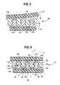
- FIG. 6is a cross-sectional view of the two opposing interlocking portions of FIG. 5 shown in an interlocked orientation
- FIG. 7is a cross-sectional view of a second embodiment of an adhesive-based reclosable fastener shown in a uni-directional alignment
- FIG. 8is a perspective view of a third embodiment of an adhesive-based reclosable fastener shown in a uni-directional alignment
- FIG. 9is a cross-sectional view of the third embodiment of the adhesive-based reclosable fastener of FIG. 8 taken along line 9 - 9 ;
- FIG. 10is a perspective view of a fourth embodiment of an adhesive-based reclosable fastener shown in a uni-directional alignment
- FIG. 11is a cross-sectional view of the fourth embodiment of the adhesive-based reclosable fastener of FIG. 10 taken along line 11 - 11 ;
- FIG. 12is a perspective view of a fifth embodiment of an adhesive-based reclosable fastener shown in a multi-directional alignment
- FIG. 13is a cross-sectional view of the fifth embodiment of the adhesive-based reclosable fastener of FIG. 12 taken along line 13 - 13 ;
- FIG. 14is a cross-sectional view of two opposing interlocking portions containing the adhesive-based fastener of FIG. 12 in an interlocked orientation;
- FIG. 14Ais a top view of superimposed images of interlocked fasteners showing an exemplary degree of overlap between adjacent fastener portions;
- FIG. 15is a perspective view of a sixth embodiment of an adhesive-based reclosable fastener shown in a multi-directional alignment
- FIG. 16is a cross-sectional view of the sixth embodiment of the adhesive-based reclosable fastener of FIG. 15 taken along line 16 - 16 ;
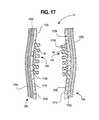
- FIG. 17is a cross-sectional view of another exemplary adhesive-based reclosable fastener
- FIG. 18is a perspective view of an exemplary flexible package having an adhesive-based reclosable fastener thereon illustrated in an open condition;
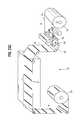
- FIG. 19is a perspective view of an exemplary rigid package having an adhesive-based reclosable fastener thereon;
- FIG. 20is a perspective view of a second embodiment of an exemplary package with a pivotable cover, the package having an adhesive-based reclosable fastener thereon;
- FIG. 21is a perspective view of a third embodiment of an exemplary rigid package having an adhesive-based reclosable fastener thereon;
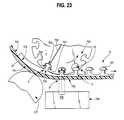
- FIGS. 22 and 23Care exemplary processes to apply the adhesive-based reclosable fastener to a package substrate
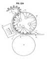
- FIGS. 22A , 23 , 23 A, and 23 Bare cross-sectional views of exemplary molding and curing stations
- FIGS. 24 , 24 A, and 25are exemplary processes to prepare packages with the adhesive-based reclosable fastener
- FIGS. 26A and 26Bshow an exemplary adhesive based reclosable fastener with non-interference coupling portions
- FIGS. 27A and 27Bshow another exemplary adhesive based reclosable fastener with non-interference coupling portions
- FIGS. 28 and 29compare shear forces upon opening to peel forces upon opening of fasteners herein;
- FIG. 30is a cross-sectional view of an exemplary mating closure referred to in some of the Examples.
- FIG. 31are images of Instron tests for some of the Examples.
- the fastenercan be supported upon opposing substrate portions and includes fastening elements that have both mechanical and adhesive characteristics that can be coupled or mated together to form a reclosable seal.
- the mechanical mating elementsinclude interlocking or mating portions that can have cooperating coupling parts configured to provide mechanical locking or mating of the cooperating coupling parts when coupled together.
- the adhesive mating elementsinclude adhesive contacting portions of the cooperating coupling parts that are formed of an adhesive, cohesive, or other bonding material, such as an acrylic composition, that can form a bond between the contacting portions and is configured to also provide an adhesive bond of the cooperating coupling parts when coupled together.
- the adhesive mating elementsinclude a configuration that exhibits a shear force and, in some cases, both a shear force and a peel force upon opening of the fastener.
- the fastenermay include both interference and/or non-interference mechanical mating elements.
- the hybrid combination of both mechanical and adhesive mating elements in the same fastener componentprovides an enhanced reclosable seal over fasteners having separate mechanical and adhesive seals.
- the fasteners hereinmay also have an increased surface area available for adhesive mating to the structures and shapes of the mechanical mating elements.
- the adhesive contacting portions and, in some cases, the entire cooperating coupling parts themselvescan be formed from an adhesive or a material with self-bonding capabilities.
- the adhesiveis an acrylic adhesive having an energy-curable acrylic oligomer, a tack control component and, optionally, at least one elastomeric component.
- the acrylic adhesivecan be cured while in contact with a flexible and perhaps transparent mold to form the reclosable fastener where the cooperating coupling parts define mating undercut surfaces forming the mechanical mating portion of the fastener.
- portions of fastener, and in some cases, the mating undercut surfacescan mechanically mate or interlock and, at the same time, also adhesively bond together the opposing substrate surfaces by providing an interference engagement and an adhesive bond therebetween.
- the cooperating coupling partscan define mating undercut surfaces with a male portion on one mating portion and a female portion on the other mating portion or, in another instance, a tongue on one mating portion and a complementary groove on the other mating portion.
- the cooperating coupling partscan have a three-dimensional geometry where, in one approach, the interlocking portions can be a multi-directional mating configuration or, in another approach, the mating portions can be a uni-directional locking configuration. Other mating orientations of the cooperating coupling parts may also be employed.
- the cooperating coupling partsalso exhibit adhesive bonding properties, such that the cooperating coupling parts of the hybrid reclosable fastener can also adhesively bond to each other upon contact in addition to forming the mechanical mating or coupling between the cooperating coupling parts.
- an acrylic adhesiveis employed that exhibits relatively low-tack properties that provides for the cooperating coupling parts to also releasably bond to the opposing parts of the fastener.
- the reclosable fasteneris bonded to a substrate with a sufficient bond strength such that the opposing layers of the mating portions do not delaminate from the substrate when the opposing mating portions are separated from each other even when the adhesive used to form the mating portions has a low tack property.
- the fastenermay have a relatively high cohesive bond strength between the opposing mating portions to form a good bond therebetween, it also has an adhesive formulation that has a relatively low tack when exposed to an unlike surface, such as surfaces of crumbs, lint, particulate, or the like.
- a bondable or adhesive material suitable for the fasteners hereinis an energy curable acrylic adhesive; however, other adhesives and bondable materials may also be suitable for the fasteners as needed for a particular application.
- the hybrid reclosable fastener having the mechanical mating properties and adhesive mating propertiesallows for repeated resealing of the opposing mating portions with consistent peel strengths even when contaminated with debris.
- This resealable characteristicis not diminished even by exposure or contact with foods or materials that tend to diminish the adhesive bonding strength of other adhesive fasteners, such as fine particulate of less than about 150 microns, materials with high moisture, and/or materials with a fatty content.
- the reclosable fastener hereinis effective to reseal opposing faces of a substrate repeatedly even after contact with powdery materials such as roast and ground coffee, powdered beverages, shredded cheese, liquids, fatty products, and other fine powders.
- ACRadhesive component ratio
- Other possible characteristicsmay be an effective surface energy parameter that controls the bond strength interface between the substrate 12 and the mating portions 14 . Surface energy is discussed in more detail below.
- the configuration of the cooperating coupling partsis shaped to define the mating undercut features, which aids in the ability to provide this unique resealability of the adhesive contacting portions even when contaminated with debris.
- the undercut featuresdefine at least some of the adhesive contacting portions of the fastener. These adhesive contacting portions are surfaces underneath an upper protruding surface or enlarged portion of the coupling parts. Thus, the adhesive contacting portions are not generally directly exposed or directly visible from an upper surface of the reclosable fastener. As a result, the protruding or enlarged portions of the coupling parts protect the adhesive contacting portions from debris and can maintain a surface underneath the undercut portion substantially free from the potential of being contaminated.
- the protected adhesive contacting portionswill still provide mechanical mating or interlocking as well as still provide a sufficient bond of the adhesive on these protected undercut portions thereof because these portions tend to remain substantially free of contamination. Therefore, the combination of a mechanical and cohesive bond provide for enhanced sealing and enhanced air tightness over just a mechanical closure on its own.
- the opposing layers of the hybrid fasteners hereincan be applied on a variety of substrates such as packaging materials, including, for example, film, paperboard or other paper products, cardboard, foil, metal, laminates, flexible, rigid, or semi-rigid plastic products, or combinations thereof to name a few.
- packaging materialsincluding, for example, film, paperboard or other paper products, cardboard, foil, metal, laminates, flexible, rigid, or semi-rigid plastic products, or combinations thereof to name a few.
- these materialscan be used to create a variety of packages or containers, including, for example, flexible pouches or bags, cartons or boxes, sleeves, and clamshell packages, to name a few.
- the hybrid fastenersmay also be used on many other substrates that may use a fastener that is reclosable.
- hybrid fasteners herein on disposable diapersas fasteners on articles like athletic shoes, fasteners for jacket front openings, fasteners for pocket closures, or other types of clothing apparel, fasteners for office or school supplies such as folders and portfolios, closures on camping tents or back packs, as repositionable labels or markers for posters and maps for educational supplies/classroom instructional materials, fasteners for arts and crafts such as scrap-booking, repositionable fasteners for board game pieces, or repositionable strapping for bundling goods during shipping that are easy to apply and remove.
- FIGS. 1 and 2show generalized approaches of exemplary hybrid reclosable fastener 10 including both mechanical mating and adhesive-based mating elements within the same fastener component.
- the fastener 10generally includes a substrate 12 having opposing substrate portions 12 a and 12 b thereof for supporting the reclosable fastener 10 .
- the fastener 10has opposing interlocking or mating portions 14 with interlocking or mating portions 14 a and 14 b on each of the opposing substrate portions 12 a and 12 b , respectively.
- the mating portions 14 a and 14 bare configured and at least partially formulated out of a material to provide both mechanical mating and adhesive mating of the fastener 10 and, at the same time, permit repeated opening and reclosing of the fastener with consistent bond strengths even when contaminated.
- the mating portions 14 a , 14 bdefine cooperating coupling parts 16 and 18 that are configured to couple together in a mating relationship to mechanically couple, mate and/or lock the portions 14 a and 14 b together when coupled due to an interference therebetween.
- the cooperating coupling parts 16 and 18also include one or more adhesive contacting portions 20 and 22 thereof that are positioned to contact each other when the cooperating coupling parts 16 and 18 are coupled together so that the contacting portions 20 and 22 form a cohesive bond therebetween.
- FIGS. 1 and 2show exemplary adhesive contact portions 20 and 22 on each of the coupling parts 16 and 18 , but these contacting portions are only exemplary and the locations and positions may vary depending on the specific configuration of the fastener.
- one of the coupling parts 18defines a protruding stem or post 24 with an enlarged outer segment or bulbous end 26 at a distal end 30 thereof.
- the post 24may be a discrete member or the cross-section of a longitudinal rib extending the length of the fastener.
- the opposing coupling part 16may then define a cooperating pocket or receptacle 27 for mating reception of the post 24 and bulbous end 26 of the other coupling part 18 .
- the receptacle 27may be a discrete pocket or a groove that extends the length of the fastener.
- each of the opposing coupling parts 16 and 18may define similar protruding stems or posts 24 having the enlarged end portion 26 .
- one or both of the coupling partsmay include a plurality of adjacent posts 24 to define a space or cavity 28 therebetween for receiving the enlarged portion 26 and post 24 of the cooperating coupling part on the opposite mating portion.
- the various adhesive contacting portionswill adhesively bond together in various adhesive bonding surfaces.
- the fastener 10has a three-dimensional shape or geometry and at least portions thereof are formulated out of an adhesive-based material to provide an enhanced bond and enhanced air tightness between the opposing portions 12 a and 12 b even when the fastener is contaminated with debris, moisture, fats, and the like.
- the shape and formulationis also effective to provide for repeated opening and reclosing with little to no drop in the bond strength between the opposing portions even when so contaminated.
- Prior mechanical fastenerstend to show a difficulty in mating when contaminated with debris and have limited ability to form a hermetic seal.
- Prior adhesive fastenerscan result in a diminished ability to form a bond when contaminated with fine particulate, moisture, and lipids.
- the fasteners hereinhave a unique configuration to protect the adhesive contacting portions 20 and 22 from debris to provide not only a mechanical mating but also an adhesive bonding as well.
- the generalized cooperating coupling parts 16 and 18 of the mating portions 14 a and 14 b shown in FIGS. 1 and 2may take on any number of shapes and configurations that are appropriate to provide mating of the cooperating coupling parts 16 and 18 when coupled together. Examples of some suitable shapes are described further below.
- the hybrid mechanical mating elements and the adhesive mating elements of the fastener 10combine to provide a first or initial bonding or peel force between the opposing substrate portions 12 a and 12 b of about 80 to about 900 grams per linear inch (gpli). These hybrid mating elements also provide up to at least five subsequent peel forces between the opposing substrate portions 12 a and 12 b of about 60 to about 900 gpli. Even when contaminated (as discussed in more detail below), the hybrid mating elements still provides an enhanced bond having a peel force of about 60 to about 900 gpli.
- the hybrid mechanical mating elements and the adhesive mating elements hereinalso combine to provide an improved level of air-tightness when compared to a fastener of substantially identical geometry made from a non-cohesive material. While not wishing to be limited by theory, it is believed that such enhanced bond is due, in part, to the unique combination of mechanical mating features, undercut mating surfaces, adhesive mating features, protection of the adhesive bonding portions from contamination, and/or the formulation of materials used to form the fastener.
- the cooperating coupling partscan be coupled together as a reclosable fastener depending on how the mating portions are constructed and aligned.
- the mating portionsmay be configured for uni-directional alignment or alignment in a single linear direction.
- the portionsare configured for a multi-directional alignment or alignment in multiple directions.
- an exemplary uni-directional alignmentcan include cooperating coupling parts having a tongue on one mating portion and a complimentary groove on the other mating portion defined by longitudinal ribs on the fastener portions.
- Uni-directional alignment of the coupling partsprovides for the coupling parts to be based on parallel mating ribs. To close the fastener, the uni-directionally aligned coupling parts can be brought together with the mating ribs on each opposing strip roughly parallel to one another in order to reseal successfully.
- the multi-directional alignmentcan include cooperating coupling parts having a plurality of spaced mating protrusions on each of the mating portions, such as a plurality of spaced male parts and a plurality of spaced female parts.
- This arrangementprovides for a multi-directional coupling or mating, where the male part is inserted into any of the cavities formed in between the adjacent female parts.
- the multi-directionally aligned coupling partscan be resealed regardless of orientation of the opposing substrate portions. Many other mating feature geometries are possible with either approach. These will be better described below in reference to the Figures.
- an exemplary uni-directional locking or mating fastener 100is provided utilizing a tongue and groove-type assembly with a tongue 132 and groove 134 provided on each of the opposing mating portions 114 .
- the tongue 132may be a post 124 with an enlarged end segment 126 at a distal end 130 thereof that extends along the entire length of the fasteners' mating portions 114 as generally shown in FIG. 3 .
- the groove 134may be defined between two adjacent rows of tongue portions 132 where a cavity 128 is formed by facing sidewalls 125 of the immediate adjacent pair of posts 124 .
- the cavity 128 that forms the groove 134may define a circular pocket or receptacle configured to receive the tongue 132 therein as shown in FIGS. 5 and 6 .
- the tongue 132 on one mating portionis aligned with and pressed into the groove 134 of the opposing mating portion when coupled together.
- the tongue 132 and groove 134each extends along the length of the mating portion in a generally parallel fashion, each is generally aligned with the other in order to receive the tongue in the groove and mechanically couple or mate the two together.
- the tongue and groove assemblyprovides a single direction or uni-directional mechanical mating in which the two mating portions can be coupled together once the rows of opposing tongue and groove portions are aligned.
- the enlarged end section 126may define an outer or top flat surface 133 at the distal end 130 of the post 124 with inclined side portions 131 that extend outwardly and away from the flat surface 133 beyond the width of the lower post portion 124 to define the enlarged end section 126 .
- the side slanting portions 131may have an angle of inclination ⁇ that is about 20 to about 40 degrees from a vertical axis extending through the groove 134 , in some cases, about 20 to about 30 degrees, and in other cases, about 25 degrees; however, other appropriate inclinations can be provided as needed for a particular application.
- the walls 125 of the post 124curve inwardly and define a concave surface extending away from a lower end of the inclined side portion 131 .
- the curved walls 125define the concave pocket or the cavity 128 of the groove 134 in this approach.
- the enlarged end section 126also defines an undercut mating surface 129 that is configured to mechanically couple or mate the mating portions together when coupled as shown in FIGS. 5 and 6 .
- FIGS. 5 and 6show the fastener 10 being coupled and in a coupled state to show both the mechanical mating of the cooperating coupling parts due to one or more interferences of the undercut mating surfaces 129 as well as the adhesive bonding due to the engagement of the various contacting adhesive mating surfaces 120 and 122 .
- the undercut mating surfaces 129couple or mate the portions together due to an interference thereof along an axial direction of the fastener posts 124 .
- the hybrid fastener 100also has pairs of contacting adhesive contact portions 120 and 122 formed from an adhesive material to form an adhesive bond therebetween.
- the adhesive contacting portions 120 and 122are generally formed in an adhesive bonding surface A extending transverse or inclined to a plane of the opposing substrate portions 112 a and 112 b .
- the surfacecan be linear, curved, or flat. With multiple adhesive contacting portions 120 and 122 , then more than one adhesive bonding surface A may be present.
- the coupled fastenerhas at least two intersecting bonding planes A that extend in different directions that may aid, in some cases, to form a more robust sealing bond between the coupling parts because the adhesive bonding is at an angle relative to the substrate.
- the post 124may be entirely formed form the adhesive material, the post and enlarged end 126 thereof may be resilient or flexible to allow flexing and/or compression thereof to allow the tongue 132 to be received within the groove 134 .
- the repeating pattern of the mating portionsmay occur at a frequency of about 12 to about 500 per linear inch, and in some cases, about 12 to about 200 per linear inch.
- the patterns of the fasteners in FIGS. 3-6have a center-to-center distance between adjacent parallel ridges of about 0.002 to about 0.067 inches, or about 12 to 500 ridges per linear inch.
- the mating portion 214 of FIG. 7has a similar tongue and groove-like arrangement as the components of FIGS. 3-6 ; however, the posts 224 in this approach are modified to provide a greater frequency of cooperating coupling parts per linear inch.
- the more closely spaced coupling parts in this approachi.e., high frequency
- the parallel rows of posts 224 and grooves 228 in this approachare positioned slightly closer together than in the previous embodiment such that a smaller groove 234 is formed.
- an aspect ratio of the height H 1 of the post 224 plus the enlarged end segment 226 relative to width W 1 of the groove 234 at its widest pointis larger in this approach.
- the aspect ratio of the cooperating coupling parts in FIG. 7may be about 0.03 inches high over 0.02 inches wide or about 1.5 while the aspect ratio of the fastener in FIGS. 3-6 may be about 0.05 inches over 0.04 inches or about 1.25.
- FIGS. 8 and 9alternative uni-directional mating portion 314 is shown in FIGS. 8 and 9 .
- the mating portion 314defines a tongue 332 and groove 334 arrangement similar to the previous approaches; however, the post and enlarged portion forming the tongue and the cavity forming the groove are modified relative to the other approaches.
- an enlarged portion 326 at a distal end 330 of the tongue post 324is curved or rounded in a convex fashion. The curvature of the enlarged portion 326 curves out and away from a body 325 of the post 324 starting at an intermediate location point 327 thereof to form a globe or ball-shaped outer end of the tongue 332 .
- the post body 325also has side walls that taper outwardly and away from intermediate body point 327 toward the substrate 312 . Facing portions of the curved enlarged portion 326 and facing portions of the tapered body 325 form a cavity 328 of the groove 334 .
- the cavity 328is configured for receipt of a cooperating enlarged portion 326 from an opposing substrate 312 for the mechanical mating of the fastener.
- the groove 334has the cavity 328 that is generally not round as in the previous embodiments, but rather has a somewhat hexagonal shape formed from the facing tapered walls 325 a and 325 b of the body 325 and a generally flat bottom wall 329 .
- the tongue and grooveextend in generally parallel rows along the entire length of the mating portion 314 as generally shown in FIG. 8 .
- an alternative uni-directional mating portion 414is shown in FIGS. 10 and 11 .
- the tongue and groove assemblydefines multiple mating portions to provide for a plurality of mechanical and adhesive mating sites. It is believed that this approach may provide an even higher bonding strength due to the V-shaped edges, which provides more mechanical mating and more contact for adhesive bonding.
- the mating portion 414includes a tongue 432 and groove 434 that extend along the length of the mating portion 414 in generally parallel rows to form a uni-directional fastener.
- This fastenerincludes a plurality of adjacent ridges 424 . Each ridge 424 defines the tongue 432 and a cavity 428 between adjacent rows of ridges 424 defines the groove 434 .
- outer side walls 425 of the ridge 424define at least one and, in some cases, a plurality of indentations or teeth 436 along its side edges.
- these teeth 436are a plurality of V-shaped microprotrusions that extend outwardly into the cavity 328 from the side surface of the ridge 424 .
- each side wall 425includes at least one and, in some cases, a plurality of adjacent teeth. Three are shown, but more or less may be used as needed.
- the teethare configured in a V-shape where each tooth is defined by facing ridge walls 427 that taper away from each other into the cavity 428 . Other shapes, sizes, and numbers of the teeth may also be appropriate as needed for a particular application.
- the distal end 430 of the ridge 432includes an outer cap 426 with no teeth 436 having side walls 431 that taper inwardly toward each other similar to the approach shown in FIG. 3 .
- the tapered shape of the end cap 426aids in inserting the tongue 432 into the groove 434 .
- each of the teeth 436 of one tonguemechanically couple or mate with adjacent teeth from the adjacent tongue to provide multiple mating points as generally due to multiple interferences 429 as the facing tooth walls 427 abut each other.
- each of the tooth walls 427can contact another facing tooth wall on the adjacent post to form multiple adhesive contact portions along a variety of adhesive contacting planes that extend at an angle ⁇ to the opposing substrate surfaces.
- the cap 426may also have a relatively flat upper end surface 433 with the tapered side walls 431 .
- This flat end wall 433may also form yet another adhesive contacting portion with the base 429 of the cavity 434 to form an adhesive contacting plane that is generally parallel with the substrate portions 412 .
- the end cap 426in this approach, generally does not extend beyond outer peaks or intersection points 437 of the tooth walls 427 of the ridge teeth 436 .
- the multi-directional mating portionsinclude a plurality of discrete and spaced cooperating coupling parts that define a three-dimensional matrix of protrusion-like members that form mechanical and adhesive mating by mating the two opposing portions together in more than one direction and, in some cases, any direction.
- the multi-directional mating portionsare advantageous because they allow the opposing substrate portions to be fastened together in multiple alignment.
- a multi-directional mating portion 514can be provided with a plurality of spaced protrusions 532 as generally shown in FIGS. 12-14 .
- the protrusions 532may be disposed on a base 515 in a series of rows 516 in which the protrusions 532 are spaced apart within the rows, but are also oriented in a staggered or offset alignment with respect to the protrusions in adjacent rows, as generally shown in the perspective view of FIG. 12 .
- a reclosable fastener including the multi-directional mating portion 514one approach would use the portion 514 for each of the opposing mating portions 14 .
- each protrusion 532may include a post 524 extending outwardly from the base 515 and an outer cap or enlarged portion 526 at a distal end 530 thereof such that the protrusion 532 is generally in the form of a mushroom-shape member.
- the outer cap or enlarged portion 526can have any appropriate shape and, in the instance shown in FIG. 13 , includes a convex or rounded outer wall 527 defining an enlarged dome that extends beyond the outer walls of the post 524 .
- the bottom of the cap 526defines a ledge 529 due to the outer wall 527 terminating at a lower edge 531 that is spaced a distance beyond a side wall 533 of the post 524 .
- Each protrusion 532forms one of the cooperating coupling parts of the mating portion 514 .
- the plurality of spaced protrusions 532 arranged adjacent one anotherdefine a cavity or well 528 between adjacent posts 532 a , 532 b , 532 c , and 532 d for example to provide a pocket 534 for receipt of a post 532 from an opposing mating portion 514 .
- the pocket 534is generally formed from the four adjacent posts 532 a - d .
- the coupling partscan be brought together and pressed together such that a post 532 from one mating portion 514 couples and mates with four adjacent posts from an opposing portion 514 as generally shown in the cross-sectional view in FIG.
- undercut portions 529 of the protrusions 532are formed by the ledges 529 of the upper caps 526 . These undercut portions, when coupled to the opposing mating portion, form a mechanical mating due to the ledges 529 abutting and forming an interference with each other along an axial direction of the post 524 as generally shown in FIG. 14 .
- the contacting of the ledges 529also define adhesive contacting portions 520 and 522 where the ledge 529 from one cap is adhesively bonded to the ledge 529 on another cap along an adhesive bonding plane A.
- a top or apex 527 a of the dome wall 527may also contact the base 515 to form an adhesive contacting portion therebetween along an alternative adhesive bonding surface.
- adhesive bondingmay occur between the ledges as well as the cap/base interface.
- the spacing and amount of overlapping contacting portions between adjacent protrusionsmay be selected so there is a sufficient degree of mechanical interference and contacting surface area for adhesive bonding.
- FIG. 14Aprovides an example of such overlapping surface area.
- the dome-shapeaids in inserting the protruding post and dome into the opposing cavity.
- areas of overlap 529represent an exemplary degree of mechanical interference and the contacting surface areas between the coupling parts of the fastener on each of the opposing portions.
- FIGS. 15-16Another embodiment of a multi-directional mating portion 614 is shown in FIGS. 15-16 .
- the mating portion 614includes a similar matrix of protrusions 632 spaced in parallel rows about a base 615 . If desired, the spacing of the protrusions may be closer than those in the previous approach. However, the spacing may vary as needed for a particular approach.
- each protrusion 632has a generally frusto-conical shape including a lower post portion 624 with an inwardly curved or concave outer wall 633 and an upper enlarged portion 626 having an inwardly tapering annular side wall 631 with a generally flat top wall 627 .
- the inward taper of the side wall 631may range from about 20 to about 30 degrees and, in some cases, about 25 degrees from a vertical axis extending through the post portion 624 .
- Each protrusion 632may form one of the cooperating coupling parts of one of the mating portions 614 .
- the plurality of spaced protrusions 632 arranged adjacent one anotherdefine a cavity or well 628 between adjacent protrusions 632 a , 632 b , 632 c , and 632 d to provide a pocket 634 for receipt of a post 632 from an opposing mating portion 614 .
- the pocket 634is generally formed from the four adjacent posts 632 a - d .
- This pocket 628forms another of the cooperating coupling parts of the fastener.
- less contact areamay be desirable for certain applications where very low opening force is required. Not being off-set may simplify manufacturing.
- a tapered headmay be easier to extract from a mold compared to a mushroom shaped head.
- the coupling partscan be brought together and pressed together such that a post 632 from one mating portion 614 couples and mates with four adjacent posts from an opposing portion 614 .
- undercut portions 629 of the protrusions 632are formed by the concave side wall 633 of the post portion 624 ( FIG. 16 ). These undercut portions, when coupled to the opposing mating portion, form a mechanical mating due to the upper curved portions thereof abutting and forming an interference with each other along an axis of the post.
- the contacting of the upper curved portionsalso define adhesive contacting portions where the curved walls 633 from one protrusion is adhesively bonded to the curved wall 633 or the tapered wall 631 on another adjacent wall along an adhesive bonding surface A.
- the top or apex 627 of the upper portion 626may also contact the base 615 to form an adhesive contacting portion therebetween along an alternative adhesive bonding surface.
- adhesive bondingmay occur between other locations along adjacent protrusions.
- the mechanically and adhesively mated coupling partscan have a bond or peel force between the mating portions that must be overcome upon separating or opening the cooperating coupling parts.
- this bond or peel forcemay be a combined bond due to mechanical mating elements and adhesive mating elements.
- the mating portionsmay have an overall bonding strength of peel force from about 60 gpli to about 900 gpli that generally includes a mechanical mating portion and an adhesive bonding portion.
- the cohesiveis an acrylic adhesive that has a composition effective to maintain a consistent bonding and peel force as well as to minimize adhesion to undesired surfaces and still function, at the same time, as an effective reclosable fastener that does not delaminate from the substrate surface that it is bonded to.
- the adhesive-based fastener and substratehave a unique formulation and construction to achieve select tack and peel values of the mating portions so that the opposing substrate portions of the fastener can be opened and closed multiple times, but at the same time, not delaminate from the opposing substrate panels.
- each of the mating portionsincludes or is formed entirely out of an energy cured pressure sensitive adhesive (PSA) exhibiting cohesive properties and low tack, but, despite the low tack, still form a strong bond to the substrate forming the opposing substrate panels.
- PSAenergy cured pressure sensitive adhesive
- a cohesive-based materialtypically adheres more readily to like materials (i.e., self-adhesion) rather than to non-like materials.
- Suitable adhesive materials used hereingenerally exhibit a relatively low tack to undesired surfaces, but at the same time still exhibit a good bond strength to desired surfaces (such as no delaminating from the opposing panels), and relatively good cohesive or self adhesion bond strength to like surfaces to close the fastener, but still permit the substrate to be openable or peelable by hand.
- the selected adhesive-based materialsalso permit debonding or peeling from such like materials so that the adhesive layers may be repeatedly peeled apart without substantial damage to the adhesive, the mating features and geometries, and/or any underlying substrate material.
- the mating portions formed from the adhesive materialhave sufficient internal integrity and generally peel apart at an adhesive bonding interface substantially cleanly without substantial material picking, stringiness, delamination from the substrate material, and/or other substantial disfigurations of the material (i.e., globbing, pilling, etc.).
- the cooperating coupling partsremain intact and are generally not permanently deformed, destroyed, and/or fractured.
- the adhesive bonding component of the hybrid fasteners hereinmaintain a peel adhesion where opposing adhesive-based coupling parts contact each other with an average initial peel adhesion greater than about 80 grams per linear inch (gpli) and, in some cases, between about 200 gpli and about 900 gpli. Moreover, in some instances, the adhesive-based fasteners retain greater than about 200 gpli and/or at least about 30% to about 200% of the average initial peel adhesion after five repeated seal and unseal operations.
- a substrate having the adhesive-based fastener disposed thereonis also constructed so that a primary bond of the energy-cured, adhesive-based mating portions to the substrate is generally greater than the opening peel strength between the layers of the fastener itself.
- the mating portionsgenerally remain adhered to the substrate and do not pick, string, or delaminate from the substrate when the closure is opened by a consumer and the fastener is peeled open.
- the primary bond or peel strength of the adhesive mating portions to the substrateis greater than about 900 gpli and is capable of withstanding multiple peel and re-seal cycles without detachment from the substrate material.
- the adhesive forming the mating portionsis sufficiently cured so that it is capable of withstanding more than 100 double rubs with methyl ethyl ketone (MEK) solvent without visible damage to the adhesive.
- MEKmethyl ethyl ketone
- the opposing mating portions 14 a and 14 b including the cooperating coupling parts 16 and 18can each be formed entirely out of adhesive materials described herein.
- the entire mating portions 14 a and 14 b and cooperating coupling parts thereofhave at least outer surfaces of an adhesive material exhibiting a surface with self-adhering characteristics.
- only the outer surfaces of and, in some cases, only the adhesive contacting portions thereofare formed from the adhesive materials described herein.
- the opposing mating portions 14 a and 14 bmay be formed from a liquid adhesive mixture that may be heated and applied to the substrate material at a warm temperature, such as at about 160° F. (71° C.), but can be in the range of about 86° F. (30° C.) to about 190° F. (88° C.).
- the applied coating mixturewhich can contain an added photoinitiator, can be contacted with a flexible and transparent patterned mold while also exposed to UV treatment or electron beam treatment to cure (polymerize) the adhesive material and to form the solid adhesive-based fastener 10 into the various shapes of the mating portions on the substrate.
- the adhesive or coating mixturedoes not contain any or any substantial levels of solvent that needs to be removed and may be easily applied to the substrate on high speed coating and printing lines.
- the adhesive material for constructing the mating portions, the cooperating coupling parts, and/or the adhesive contacting portions thereofmay include specific blends of an energy-curable acrylic oligomer and a tack control agent.
- the reclosable adhesive-based fastenermay include specific blends of at least one energy-curable acrylic oligomer, at least one tack control agent, and at least one elastomer (rubber) component. Examples of suitable adhesive materials may be those described in U.S. application Ser. No. 13/035,399, which is incorporated herein it its entirety.
- This adhesivedemonstrates a unique and surprising ability to form a reclosable fastener with high self-adhesion or cohesive bonding and, at the same time, low tack to non-like surfaces.
- Other types of adhesivesmay also be used as needed for a particular application.
- the first component of the acrylic adhesivemay be one or more energy-curable acrylate or acrylic oligomers.
- the energy-curable acrylic oligomermay be an acrylic or methacrylic acid ester having multiple reactive or functional groups (i.e., acrylic or methacrylic oligomers).
- a functional groupincludes one energy reactive site.
- energy reactive sitesare most commonly carbon-carbon double bonds conjugated to another unsaturated site such as an ester carbonyl group.
- the energy-curable acrylic oligomeris an acrylic or methacrylic acid ester of a multifunctional alcohol, which means the oligomer has more than one acrylated or methacrylated hydroxyl group on a hydrocarbon backbone of the oligomer.
- the adhesivemay include about 1% to about 90% by weight of the energy-curable acrylic oligomers and with functionalities of about 1.2 to about 6.0.
- the energy-curable acrylic oligomersmay have a functionality of about 2.0 to about 3.0.
- the adhesivemay include about 20% to about 70% by weight (in some cases, about 33% to 60% by weight) of the acrylic oligomers.
- the multifunctional energy-curable acrylic acid esteris an acrylic acid ester of a vegetable oil having a reactive functionality of 2.0 or greater.
- the energy-curable acrylic oligomercan comprise an epoxidized soybean oil acrylate.
- ACRadhesive component ratio
- the amount of the energy-curable acrylic oligomers usedcan impact the properties of the final adhesive. For instance, where the amount of the energy-curable acrylic oligomer is too low, based on the preferred ACR, the cure rate of the final adhesive is too slow. On the other hand, where the amount of the energy-curable acrylic oligomer is too high, based on the preferred ACR, the final adhesive may be adequately cured, but can have inadequate self adhesion properties to seal and reseal.
- the second component of the adhesiveis a tack control agent.
- the acrylic adhesivemay include about 1% to about 65% by weight of the tack control agent.
- the tack control agentcan be present in amounts from about 20% to about 65%.
- the tack control agentcan include a tackifying resin or a curable polymer/monomer combination that when cured can produce the desired levels of tack and self-adhering properties appropriate for the reclosable fastener 10 .
- the tack control agentcan comprise an aliphatic urethane acrylated oligomer. Many other types of tack control agents suitable for energy-curable PSA adhesives may also be used in the reclosable adhesive system.
- An optional third component of the adhesiveis at least one elastomeric or rubber component.
- the elastomeric componentmay include at least one curable acrylated (i.e., acrylic modified) or methacrylated esters of a hydroxy-terminated elastomeric polymer (i.e., an elastomeric polyol).
- This elastomeric componentcan include acrylic-modified polybutadiene, a saturated polybutadiene and/or a flexible polyurethane.
- a methacrylated polybutadienecan be provided.
- the elastomeric materialcan be provided in amounts of about 0% to about 20% when used in the adhesive.
- the elastomeric materialis provided in amounts of about 5% to about 15%. Satisfactory adhesives can be made with the desired low tack, resealable properties as described herein without the elastomer component; however, it is believed that the elastomeric component aids in achieving an optimal coating performance.
- the optimal adhesive performancecan be defined by properties such as self-adhesion, tack, viscosity, durability, and cure rate, just to name a few.
- the elastomeric componentis useful for adjusting peel strength properties, substrate adhesion strength, increasing flexibility, viscosity control, and cure rate modulation.
- the Adhesive Component Ratio or ACR for the adhesiveis:
- the ACRdescribes a weight percent of the energy-curable acrylic oligomer relative to a sum of the weight percents of the tack control component and the elastomeric material.
- the ACRis effective to provide an energy-cured adhesive with an adhesive mating force exhibiting a first peel adhesion between the contacting portions of the cooperating coupling parts of about 80 to about 900 grams per linear inch (gpli).
- the ACRcan be in the range of about 0.8 to about 1.5.
- the range for the ACR of the three components in the formulationhas been found to provide a unique adhesive with a low tack property to non-like substances (i.e., machine components, crumbs, food pieces, and the like), yet can seal to itself with sufficient bond or peel strength (i.e., a good cohesive) to maintain a seal therebetween as well as resist contamination.
- the adhesive in this specific ACRalso provides for a resealable function that does not significantly reduce or lose its seal-peel-reseal qualities upon being subjected to repeated open and close operations.
- An ACR value below about 0.5is generally undesired because the adhesive would require significantly large amounts of UV energy or electron beam energy to cure.
- the adhesivewould cure quickly, but it would also have low (or no) peel strength, unacceptable for the adhesive closure herein.
- a satisfactory adhesive formulationin some cases may also have certain other parameters such as mixture-stability of the components, a certain viscosity of the formulation, a certain cure rate, and/or a certain peel strength.
- the adhesive componentsmust also be compatible with each other such that they form a stable flowable liquid mixture.
- the adhesiveis considered stable when it (at a minimum the two or three main components) remains a homogeneous liquid, i.e., there is no visible phase separation of the components and no gel formation, while being held at room temperature (about 70° F. to about 75° F.) for at least three days.
- the adhesive formulationcan have a viscosity of about 10,000 cPs to about 50,000 cPs at room temperature (about 20 to about 25° C.) and less than about 2,000 cPs at about 70 to about 75° C.
- liquid PSAWhen applying the liquid PSA to the substrate during manufacturing, it may be applied at a temperature of about 86° F. (30° C.) to about 190° F. (88° C.) and, in some cases, at about 160° F. (71° C.). These viscosity ranges provide for applying the adhesive to a substrate using conventional printing, roll coating, slot die, or embossing application techniques.
- the average initial peel strength of the mating portions constructed from a properly cured adhesivecan be in the range of about 80 gpli to about 900 gpli and, in some cases, about 280 gpli to about 800 gpli, and in other cases, about 280 gpli to about 650 gpli, as measured by a test method as set forth in the Examples.
- the adhesiveis also designed to retain its average peel strength after repeated open and close operations (i.e., adhesion retention).
- the mating portions constructed from properly cured adhesivecan retain its average initial peel adhesion between about 280 gpli and about 800 gpli up to at least five repeated peel-reseal cycles. This is called the adhesive retention value.
- the adhesion retention value upon peeling-resealing-peelingcan be between about 30% to about 200% retention of the initial value.
- the fasteners hereinalso provide a unique ability to resist contamination. Upon the fasteners experiencing contamination, the adhesion retention value may be between about 25% to about 150% of the initial value even when contacted with fine particulate, moisture, fats, and lipids.
- the mechanical mating elements and the adhesive mating elements of the fastenercombine to provide a total initial peel force between the opposing substrate portions of about 80 gpli to about 900 gpli and up to five subsequent peels between the opposing substrate portions of about 60 gpli and about 900 gpli.
- the adhesive formulationmay also include other optional features or optional compositional components that may be helpful when forming the rather complex profiles and geometries of the mating portions and the cooperating coupling parts described above.
- each of the opposing mating portions of the closurecan have the same or different adhesive compositions.
- the first mating portion 14 acan comprise the acrylic adhesive disclosed above, while the second mating portion 14 b can comprise a different adhesive formulation of a modified adhesive material so that it exhibits different properties of tack, rigidity, strength, elongation, and the like.
- each portionmay be tailored to have different adhesive properties as needed for its particular application, such as different ACR ratios, different adhesive bonding properties, different peel force values, different elongation, different tack levels, and the like.
- the two parts of the substrate closurei.e., the two opposing mating portions 14 a and 14 b
- the acrylic adhesivemay have a composition that exhibits either a pseudo plastic, such as shear thinning, behavior or a dilatant (shear thickening) behavior upon application of shear strain.
- a pseudo plasticsuch as shear thinning
- shear thinningthe adhesive thins out when it undergoes shear strain, such as may occur when the liquid adhesive is forced to flow into a mold cavity. This will be discussed in more detail below, and more effectively fills all the void spaces in the mold, then stiffens up once the adhesive is in the mold to hold its shape.
- the cooperating coupling part of one mating portionmay be more rigid than the cooperating coupling parts of the opposing mating portion and, as a result, one side of the fastener may be stronger and more rigid than the other.
- one of the cooperating coupling partsmay be more pliable and more flexible than the other, or any other combinations are possible.
- the hybrid reclosable fastenersprovides for both mechanical mating as well as a cohesive bond between opposing sides of the reclosable fastener at the same time to form, in some instances, an enhanced closure that is generally greater than the closure of either of these fasteners independently.
- the cooperating coupling partscan couple or mate with adjacent cooperating coupling parts when brought together (i.e., arrows X in FIGS. 1 and 2 ) to close the opposing substrate portions and form a mechanical coupling and cohesive bond due to the adhesive contacting portions.
- the selected pressure sensitive adhesive (PSA) forming the cooperating coupling parts 16 and 18may exhibit an initial bonding strength or initial peel strength between the coupled portions 14 a and 14 b of about 80 g/inch to about 900 g/inch (i.e., or grams per lineal inch, gpli), and in some cases, between about 200 g/inch to about 400 g/inch as measured by the ASTM peel test.
- Such initial bonding strengthsmay be a combined bond of both the mechanical and adhesive mating components in the hybrid fastener.
- the initial bond or initial peel strengthmay range from about 280 gpli to about 800 gpli.
- the mating portions 14 a and 14 b using the above described PSAmay further have a secondary or subsequent peel or bond strength (i.e., an adhesive retention) between the mating portions 14 a and 14 b after at least five open/close operations of at least about 60 gpli, or in other cases at least about 30% to about 200% of the initial peel, and, at a minimum, about 50 g/inch to about 200 g/inch, where the subsequent peels include the seal-reseal action (opening and closing) that occurs after the initial opening and separation of the hybrid fastener.
- these secondary or subsequent peel strengthsmay provide a greater level of bonding than if the fastener were constructed of a non-adhesive material or a fastener constructed of the adhesive alone.
- the mating portions 14 a and 14 bmay also maintain a bonding strength or peel strength therebetween when contaminated with food crumbs, oils, liquids, and the like between about 50 g/inch to about 900 g/inch, and exhibit a residual adhesion or residual cohesion after fouling or contamination of at least about 20%, and in some cases about 30% to about 150% of the bonding or peel strengths prior to contamination.
- Such bond strengthsare maintained even when contaminated with fine particulate having an average particle size of about 150 microns or less, moisture, fats, and lipids.
- adhesion remaining or residual cohesion after contaminationis a measurement of the peel strength after direct contact of the mating portions to food particles, fats, lipids, and other contaminants relative to the peel strength of a clean or uncontaminated fastener, exhibited as a percentage.
- the cohesive bond and mechanical mating between the cooperating coupling parts 16 and 18is generally sufficient to seal the coupling parts 16 and 18 together and, in some cases, also form a hermetic seal or a generally air tight seal.
- the adhesive used for mating portions 14 a and 14 balso preferably has a relatively low tack level or stickiness that enables the fastener to minimize and, in some cases, limit the adhesion of the fastener 10 to unwanted materials (i.e., contamination) and surfaces, such as food particles, forming equipment surfaces, rollers, and the like.
- the adhesivewhen cured as a flat-level coating, may have a tack level to undesired surfaces not exceeding about 5 psi when preloaded with about 4.5 pounds using the ASTM probe tack test D2979.
- the PSA coatingmay have a tack level not exceeding about 15 psi when preloaded with about 10 pounds.
- the tack levelmay also vary depending on the particular PSA and application thereof and measurement test used.
- the adhesive material used to make fastener 10exhibits a tack when cured as a flat level-coating as measured by a modified version of a rolling ball test in ASTM D3121 where the adhesive tack permits about 1 inch to about 8 inches of ball travel. In some cases, up to about 14 inches of ball travel.
- the modified rolling ball tack testis explained in U.S. application Ser. No. 13/035,399, which is incorporated herein in its entirety.
- the mating portions 14 a and 14 bstill form a sufficiently strong primary bond with the substrate 12 forming opposing substrate panels 12 a and 12 b so that the mating portions 14 a and 14 b are not substantially delaminated therefrom when the opposing portions 12 a and 12 b are separated.
- the primary bond strength of the adhesive-based mating portions 14 a and 14 b to the substrate 12 at an interface 22 thereofis generally greater than the peel strength or bond strength between the mating portions.
- the primary bond strength of the mating portions 14 a and 14 b to the substrate forming the opposing substrate panels 12 a and 12 bis generally greater than about 600 g/inch, in other cases greater than about 900 g/inch. In other cases, greater than about 1000 g/inch and, in yet other cases, greater than about 1200 g/inch. In other instances, the primary bond strength of the mating portions to the substrate may range from about 600 to about 1200 g/inch. However, the primary bond strength may also vary depending on the substrate, the PSA, and other factors.
- the substrate 12may be a single layer or a multi-layer film, and, in such a case, at least an innermost layer of the substrate film 12 forming the opposing substrate panels 12 a and 12 b may be composed of a polymer blend containing ethylene vinyl acetate (EVA), linear low density polyethylene (LLDPE), and adhesion promoting filler particles.
- EVAethylene vinyl acetate
- LLDPElinear low density polyethylene
- the adhesion promoting filler particlesare present in the substrate 12 (to be discussed further below), it may be present in and dispersed throughout and, at a minimum, throughout at least this innermost layer (i.e., EVA/LLDPE blend).
- EVAis the predominant component of the blend, at about 65% to about 90%
- LLDPEis a minor component of the blend, at about 5% to about 25%.
- the substrate, innermost layer, and/or the blended EVA/LLDPE layermay have low concentrations of migratory slip additives (commonly added to some packaging substrates in order to obtain a coefficient of friction suitable to process the substrate on form, fill, and seal machines).
- migratory slip additivesmay include amounts of fatty acid amides, and it has been discovered that such compounds can affect the bond strength of cohesive materials to the substrate because the slip additive may block surface sites where adhesion can take place.
- the substrate 12may have less than about 1000 ppm of fatty acid amides (i.e., migratory slip additives) throughout the innermost layer or, in some cases, throughout the entire substrate 12 .
- fatty acid amideswhich are low molecular weight components, can migrate or bloom to the surface of the substrate affecting the strength of the bond between the substrate's surface and the mating portions 14 a and 14 b .
- corona treating or flame treatingmay initially burn off any fatty acid amides on the surface of the substrate 12 resulting in an initial good bond strength to the mating portions, over time additional fatty acid amides can migrate or bloom to the substrate surface, which results in a reduced bond strength over an extended shelf life.
- the fatty acid amide content in the substratemay be reduced to levels below about 1000 ppm, in some cases, to about 700 ppm or below and, in other cases, no slip additives.
- levelsprovide for both good initial bond strength and good long term bond strength, in combination with other factors, because there are such small amounts of these impurities to bloom to the substrate surface over time.
- substrate formulation variationsmay also be combined with use of other surface treatments (corona treating, plasma treating, flame treating, and the like) or other coatings as needed for a particular application.
- the substratecan undergo a surface pretreatment to increase the surface energy, and/or application of a primer coat.
- surface treatmentsmay include corona treating, plasma treating, flame treating, and the like or chemical coatings, such as primers or adhesion promoters may also be used.
- a corona treatmentcan increase the surface energy of the substrate which improves the coating's ability to bond and remain bonded to the substrate.
- a corona pretreatmentcan include a cloud of ions that oxidize the surface and make the surface receptive to the coating. The corona pretreatment basically oxidizes reactive sites on the polymer substrates.
- corona treatingideally the surface energy after treatment should be about 36-40 dynes/cm or greater at the time of coating application.
- the corona treatment of the substrate surfacehelps to provide for a strong bond between the coating layer and the substrate surface due to the increased surface energy of the substrate.
- the combination of the corona treatment with a low concentration of a slip additive and the incorporation of a filler composition within the substrate film 12together result in a strong bond between the patterned reclosable fastener and the substrate.
- corona treating or flame treatingmay initially burn off any fatty acid amides on the surface of the film resulting in an initial good bond strength of the adhesive.
- approaches of the fasteners hereinmay use the reduced levels of fatty acid amides to minimize and reduce the latent blooming of these components.
- the substrate 12can be flexible sheet material or film, which may be formed of various plastic polymers, co-polymers, papers, foils or combinations thereof.
- the film substratemay be a multi-layer coextrusion and/or a laminate with constructions to enhance interfacial bonding with the energy-cured patterned adhesive fastener 10 .
- the polymeric layersmay include polyolefins such as polyethylene (high, medium, low, linear low, and/or ultra low density polymers including metallocene or polypropylene (oriented and/or biaxially oriented)); polybutylene; ethylene vinyl acetate (EVA); polyamides such as nylon; polyethylene terephthalate; polyvinyl chloride; ethylene vinyl alcohol (EVOH); polyvinylidene chloride (PVDC); polyvinyl alcohol (PVOH); polystyrene; or combinations thereof, in monolayer or multi-layer combinations.
- the film substrateincludes EVA.
- the film substratecan have a film thickness between about 0.5 mils to about 5 mils thick. Examples of suitable film substrate may be found in United States Publication Numbers 2008/0131636 and 2008/0118688, which are both incorporated herein in their entirety.
- the substrate 12may be a single layer or a multi-layer film.
- An exemplary multi-layer filmmay include an inner heat sealable (sealant) layer to which the mating portions 14 a and 14 b are bonded and one or more structural and/or functional layers.
- the substrate 12may include the inner sealant layer and an outer structural layer including one or more layers of high density polyethylene and/or one or more layers of nylon.
- the inner sealant layermay include various polymers and/or blends of polymers.
- the inner sealant layermay include blends of ethylene vinyl acetate (EVA), polyethylene (such as linear low density polyethylene-LLDPE), and the optional adhesion promoting filler particles dispersed throughout to be described below.
- EVAethylene vinyl acetate
- polyethylenesuch as linear low density polyethylene-LLDPE
- the optional adhesion promoting filler particlesdispersed throughout to be described below.
- the inner sealant layermay include about 60% to about 80% EVA, about 5% to about 20% polyethylene, and about 0.5% to about 20% of the adhesion promoting filler particles or a filler composition including such particles.
- EVAmay be a primary or continuous phase in which the polyethylene and filler particles/filler composition is a dispersed phase therein.
- the adhesive forming the mating portions 14 a and 14 bis applied to the inner sealant layer, which forms the inner surface of the substrate.
- the multi-layered filmmay include multiple layers such that about 85% of the total film thickness is high density polyethylene and about 15% of the film thickness is the sealant layer.
- the substratemay be a paperboard or the like material having a coating or polymer layer applied thereon.
- the coating or polymer layermay include an ethylene vinyl acetate (EVA), polyethylene, and blends thereof.
- EVAethylene vinyl acetate
- This coatingmay include the fillers described above and may also include the fillers supplied in the maleic anhydride grafted linear low density polyethylene carrier (MA-LLDPE) as described below.
- the substratemay also be a fabric, foam, or other porous materials.
- At least one portion of the construction of the substrate 12 to enhance interfacial bonding or the primary bond between the mating portions and the substratemay include the adhesion promoting filler particles mentioned above. These particles may be blended with at least a portion of the substrate, such as, the adhesion promoting filler particles blended into the inner sealant layer of a film as generally shown in FIG. 17 .
- the adhesion promoting filler particlesmay be micro- or nano-sized particles of clay, calcium carbonate, montmorillonite, microcrystalline silica, dolomite, talc, mica, oxides, (silicon oxides, aluminum oxides, titanium oxides, and the like) and other additives and/or combinations thereof, into at least the inner, sealant, or surface layer(s) of the substrate to enhance the bonding of the mating portions 14 a and 14 b to the substrate 12 a and 12 b .
- the adhesion promoting filler particlesare an organoclay, and in one aspect the organoclay may be organically modified montmorillonite or an exfoliated organoclay.
- Organoclayis an organically modified natural clay such as a montmorillonite clay that is processed or treated with surfactants such as quaternary ammonium salts.
- Montmorilloniteis a phyllosilicate group of minerals that typically comprises a hydrated sodium calcium aluminum magnesium silicate hydroxide.
- the organoclay-filled substrate and, in particular, the organically modified fillers used for the adhesion promoting filler particlescan have the ability to aid in producing operable and reclosable adhesive-based closures that do not delaminate from the substrate upon being peeled open.
- useful adhesion promoting filler particleshave a surface area greater than about 100 m 2 /gram and an aspect ratio greater than about 10.
- the organoclay used in the peelable sealing layertypically comprises a plurality of particles.
- the organoclaycomprises a plurality of particles having at least one spatial dimension less than about 200 nm.
- the organoclaycomprises a plurality of particles having at least one spatial dimension less than about 100 nm.
- the organoclaycomprises a plurality of particles having at least one spatial dimension less than about 50 nm.
- the organoclaycomprises a plurality of particles having spatial dimensions greater than or equal to about 1 nm.
- the organoclaycomprises a plurality of particles having spatial dimensions greater than or equal to about 5 nm.
- the organoclaycomprises platelets having an average separation of at least about 20 angstroms.
- the organoclaycomprises platelets having an average separation of at least about 30 angstroms.
- the organoclaycomprises platelets having an average separation of at least about 40 angstroms.
- the organoclaycomprises platelets having an average separation between from about 20 to about 45 angstroms.
- the organoclayupon combining with the thermoplastic, the organoclay remains in this state such that the average separation is maintained or increased.
- suitable flexible films forming the opposing substrate panels 12 a and 12 bmay be a polyethylene based film about 0.5 mils to about 5 mils thick and, in some cases, about 3 mils thick.
- a flexible film forming the opposing substrate panels 12 a and 12 bis shown as a multi-layer, coextruded film including a structural base of one or more layers (two are shown) of a high density polyethylene 1702 (HDPE) and an inner or adhesive receiving layer (such as the above described sealant layer) of an EVA/LLDPE heat seal layer 1704 filled with adhesion promoting filler particles 1706 .
- HDPEhigh density polyethylene 1702
- EVA/LLDPE heat seal layer 1704filled with adhesion promoting filler particles 1706 .
- the mating portions 14 a and 14 b formed of the adhesiveis applied to the inner EVA/LLDPE heat seal layer 1704 , which forms the inner surfaces of the fastener 10 .
- the adhesion promoting filler particles 1706which may be organoclay, are generally exaggerated in size for illustrative purposes, but are expected to be dispersed throughout the inner EVA/LLDPE or sealant layer 1704 , and it is expected that at least some of the adhesion promoting filler particles (identified as filler 1708 in the drawing), for example, may have at least a portion thereof exposed or protruding slightly out of an outer surface 1710 of the EVA/LLDPE layer 1704 , as generally provided in application Ser. No. 12/435,768, which is hereby incorporated herein by reference in its entirety.
- the adhesion promoting filler particlesmay not be exposed at the surface 1708 , but they may create a rougher outer surface, which increases the surface area for bonding to the adhesive. While not wishing to be limited by theory, the adhesion promoting filler particles 1708 at the surface or exposed from the surface combined with corona treatment and/or the use of certain carriers for the filler may aid in the bonding of the mating portions to the substrate, which may provide an effective primary bond to the substrate that is greater than the mechanical and cohesive peel strength between the two mating portions 14 a and 14 b .
- the bonding forceis between about 600 g/inch to about 900 g/inch between the two mating portions 14 a and 14 b , no delamination occurs from the substrate 12 during repeated peel/reseal cycles between the mating portions and the substrate when the fillers and sealant constructions described herein are used.
- the primary bond of the mating portions 14 a and 14 b to the substrate with the adhesion promoting filler particles 1706 thereinis greater than about 600 gpli and, in some cases, greater than about 900 gpli as discussed previously.
- the enhanced primary bond between the mating portions 14 and substrate 12may be due to a diffusion of the liquid or uncured adhesive used to form the mating portions 14 (prior to being cured into coupling parts) into gaps, voids, or other spacing of the adhesion promoting filler particles (such as the spacing between the organoclay platelets) and, in particular, into these gaps, void, or other spacing of the filler particles having at least a portion thereof exposed at the surface of the substrate.
- the diffused liquid adhesiveforms into a solid adhesive that may be interlocked, tied or otherwise bound to the adhesion promoting filler particles to increase the primary bond to the substrate.
- the enhanced primary bondmay also be due to an affinity of the polar portions of the adhesive to the polar filler particles.
- the filler particlesare more polar than the substrate and, thus, provide a greater bond thereto.
- Effectively dispersing the adhesion promoting filler particles in polyethylene and EVA used for the substrate and/or sealant layercan be a challenge due to incompatibility of particles and certain polymers.
- supplying the adhesion promoting filler particles using a filler composition including the adhesion promoting filler particles blended with a compatible carrierhelps aid in the mixing and dispersing of the filler into the sealant layer of one form of the substrate 12 .
- the adhesion promoting filler particles and, in some cases, the organoclaycan be supplied in a maleic anhydride grafted linear low density polyethylene carrier (MA-LLDPE).
- the carriermay be a blend of MA-LLDPE and unmodified polyethylene.
- the maleic anhydride portion of the carrierhas an affinity for the organoclay or other adhesion promoting filler particles, and the polyethylene portion of the carrier mixes well with other polymers of the sealant layer or substrate 12 .
- Exemplary filler compositionsmay be obtained from PolyOne Corporation (Avon Lake, Ohio).
- the organically modified clay particleswhich may be highly polar, and/or the maleic anhydride grafted linear low density polyethylene (MA-LLDPE) carrier resin present with the clay fillers serve to promote adhesion of the cured adhesive coating to the substrate surface by increasing the surface energy and polarity of the substrate layer.
- MA-LLDPEmaleic anhydride grafted linear low density polyethylene
- the organoclay or other adhesive promoting filler particlesmay impart surface roughness to the substrate, positively affecting the coefficient of friction of the substrate and increasing the available contact area between the substrate and the mating portions, thereby providing more sites for chemical and/or mechanical bonding to occur.
- approximately 0.5% to about 20% by weight of the filler composition in the sealant layeris expected to have a beneficial impact on primary bond strength of the mating portions 14 a and 14 b to the substrate material 12 so that the primary bond to the substrate is greater than the peel adhesion between the mating portions 14 a and 14 b such that the fastener 10 does not delaminate upon opening.
- the adhesion promoting filler particlesmay roughen the surface of the substrate layer enabling it to slide freely over metal or plastic surfaces of packaging equipment without binding, thus enabling the reduction or elimination of a migratory slip additive in the film.
- the inner sealing layer having the adhesion promoting filler particleshas a higher degree of surface roughness, such as an average roughness of about 100 to about 30,000 angstroms, and in some cases, about 1500 angstroms to about 5000 angstroms.
- the sealing layermay also have a higher tensile modulus than layers without the filler.
- the inner sealant layerhas a tensile modulus of about 500 to about 2000 mPa.
- the fastener 10may be used on flexible-type packages (such as a pouches, bags, sachets, and the like) as generally shown by the example in FIG. 18 as well as more rigid packages, such as boxes, cartons, envelopes and the like as generally shown by the examples of FIGS. 19-21 .
- flexible-type packagessuch as a pouches, bags, sachets, and the like
- more rigid packagessuch as boxes, cartons, envelopes and the like as generally shown by the examples of FIGS. 19-21 .
- other applicationsare also possible.
- the flexible packagemay include a plurality of walls or panels that form a cavity therein configured to receive one or more products.
- the packagefurther includes opposing panels of packaging substrate configured to join together to restrict or block access, to contain items, and/or to preserve freshness.
- the reclosable fastenerincluding both mechanical mating as well as adhesive mating elements or characteristics, can be disposed on the opposing panels to provide a reclosable package. So configured, a user can separate the opposing panels and the opposing mechanically coupled and adhesive portions disposed thereon to access the one or more products in the cavity.
- the usercan join the opposing panels together, such as by shifting the panels toward each other or pivoting one or both of the panels with respect to the other, and applying slight pressure to couple the cooperating coupling parts together as well as to adhere the opposing adhesive portions thereon, which recloses the package.
- These open and reclose operationscan be repeated several times with minimal to no loss of bond strength of the reclosable fastener.
- FIG. 18generally illustrates an exemplary flexible package utilizing the hybrid mechanical and adhesive-based reclosable fastener 10 .
- FIG. 19generally illustrates a package 20 in the form of a more rigid hinged-type box suitable for containing one or more items, such as gum pieces.
- FIG. 20is a box or carton 20 having the hybrid mechanical and adhesive-based reclosable fastener 10
- FIG. 21shows an envelope or paper-based pouch 20 utilizing the hybrid mechanical and adhesive-based reclosable fastener 10 .
- FIGS. 18-21simply show examples of packages and other types, sizes, and configurations of the package, containers, objects and the like may also be used as needed for a particular situation.
- the package 20may also include a dead fold 46 along a bottom edge 48 thereof and transverse or side seals 50 along side edges 52 thereof so that the package 20 forms a cavity 54 between the front panel 42 and the back panel 44 for containing an item, such as a food item, comestible, or other material.
- the package 20may further include a top seal 51 above the hybrid mechanical and adhesive-based reclosable fastener 10 , when the package 20 is oriented in an upright position. It will be appreciated that the form of package 20 is only an example of but one type of a package suitable for use with the hybrid mechanical and adhesive-based reclosable fastener 10 .
- the package 20may further include other folds, seals, gussets, and/or flaps as generally needed for a particular application.
- the package 20may also include a bottom seal at the bottom edge 48 instead of a fold 46 .
- the package 20may also include non-reclosable peel seals 11 either above or below the reclosable fastener 10 as generally provided in U.S. application Ser. No. 11/267,174, which is hereby incorporated herein by reference in its entirety.
- the package 20may also optionally include a rupturable line of weakness 13 between the reclosable fastener 10 and an upper end of the package 20 , which, upon complete rupturing, is adapted to remove a portion of the upper end of the package 20 by providing a removable shroud 15 above the reclosable fastener 10 to provide a package opening.
- a rupturable line of weakness 13between the reclosable fastener 10 and an upper end of the package 20 , which, upon complete rupturing, is adapted to remove a portion of the upper end of the package 20 by providing a removable shroud 15 above the reclosable fastener 10 to provide a package opening.
- the packages 20 of FIGS. 19-21are formed from one or more portions, panels, or pieces of material or substrate 12 formed into opposed front and back panels, walls, and the like (shown as panels 42 and 44 in the Figures).
- the opposing wallsalso have opposing portions or mating portions 14 a and 14 b disposed thereon.
- the packagecan take a variety of forms having a variety of configurations or openings therein suitable for closure by the reclosable fastener 10 , and specifically the opposing portions or mating portions 14 a and 14 b.
- a usersqueezes or presses the opposing panels 12 a and 12 b together in the direction of arrows X, as shown in FIGS. 1 and 2 , to engage the opposing mating portions 14 a and 14 b to couple or mate the coupling parts as shown in FIG. 5 and to form the mechanical mating as well as a cohesive bond between the adhesive contacting portions 20 and 22 .
- the mating layers 14 a and 14 bare configured to be closed and re-opened multiple times and, in some cases, the layers 14 a and 14 b preferably have sufficient structural and bond integrity to be closed and opened about 5 to about 10 times or more with no substantial permanent deformation, delamination, or diminishing of the bonding strength between the mating portions.
- particular layers and packagescan be configured to be opened and closed any number of times depending on the particular configuration, coating weight, and other parameters of the cohesive layers and package substrate.
- the fastener 10may be used on packages to store a wide variety of food as well as non-food items.
- Food items that may be storedcan include, but not limited to, snacks, trail mix, nuts, seeds, dried fruits, cereals, cookies, crackers, snack chips, chocolate, confections, and the like.
- Packages using the fasteners hereincan also be used to store beverages, cheese, meat, cereal, ground coffee beans, desserts, pet food, liquids, other fine powders, and the like.
- foods or materials that have a fine particulate sizeare particularly suited for use with this fastener because it will not substantially diminish in bonding strength if exposed to contamination from these types of products.
- Other possible applications of the packages using the fasteners hereincan include packaging for various items that will benefit from resealability and permit multiple openings. This can include non-food items, such as potting soil, household storage bags, first aid kits, nuts and bolts, office supplies, cleaning supplies, laundry supplies, disposable eating utensils, CDs and/or DVDs, toys, modeling supplies, art and craft supplies, electrical supplies, and the like. Many other examples are, of course, possible.
- the hybrid mechanical and adhesive fastener described hereincan also be used for non-packaging applications, such as for consumer products that require a reusable fastener.
- the fastenerscould be used for disposable diapers, as fasteners on articles like athletic shoes, fasteners for jacket front openings, fasteners for pocket closures, or other types of clothing apparel, fasteners for office or school supplies such as folders and portfolios, closures on camping tents or back packs, as repositionable labels or markers for posters and maps for educational supplies/classroom instructional materials, fasteners for arts and crafts such as scrap-booking, repositionable fasteners for board game pieces, or repositionable strapping for bundling goods during shipping that are easy to apply and remove.
- hybrid fastenerand possible uses thereof has been described, exemplary methods of manufacture will be illustrated by reference to FIGS. 22 to 25 .
- the formation of the hybrid fastenersis described together with a flexible film. It will be appreciated, however, that other manufacturing methods could be used to form and apply the hybrid fasteners herein to other types of substrates and objects.
- FIG. 22shows an example of a suitable process 700 that may be used to apply, form, and cure the mating portions 14 on a substrate 12 thereby creating the shapes and profiles defining the cooperating coupling parts. It will be appreciated that other application processes or methods may also be used as needed for a particular application.
- the substrate having the hybrid fastener thereoncan be a film wound up into a roll that is later transferred to a form, fill, and seal machine to form the package.
- the substrate 12is a flexible film 701 provided in a large jumbo or roll 702 , which may be the single layer or multi-layer film described above.
- the film 701may have the EVA/LLDPE sealant layer as its inner layer 704 to which a liquid adhesive 703 is applied.
- the film 701is unwound and directed to an adhesive application station 706 where an uncured liquid adhesive 703 is applied to the inner layer 704 of the substrate 701 via an applicator 707 .
- the liquid adhesive materialsmay be applied with a viscosity of about 2,000 cPs or less at about 70 to about 75° C. When applying the liquid adhesive, it may be applied at a temperature of about 160° F.
- the adhesivemay be applied to the film 701 as a transverse strip 716 , as generally shown in FIG. 22 , using any roll coating, die extrusion, printing, rotogravure, or flexographic printing process suitable to apply a strip of the adhesive to the film. As shown, the exemplary process uses an applicator 708 , a ANILOX roll 710 , and an imaged roll 712 . In some approaches, the adhesive may be diluted in ethyl acetate solvent and applied at room temperature.
- the coated substratepasses to a curing station 718 shown in FIGS. 22 , 23 , and 23 A.
- a patterned roll-mold 720is positioned adjacent a backing roll 721 between which the coated substrate passes.
- the adhesiveis contacted with the mold 720 and pressed 730 into cavities 722 of the mold to fill up the cavities 722 with the liquid and uncured adhesive as generally shown in the exemplary approach of FIGS. 22 , 22 A, and 23 at position A.
- the roll-mold 720is configured to form the liquid adhesive into the shapes of the various mating portions 14 discussed above.
- the roll-mold 720defines cavities 722 that are shaped and sized as the desired mating portions 14 and coupling parts thereof. Because the desired shapes of the coupling parts of the mating portions can include, for example, bulb-like or mushroom-like shapes with the corresponding undercut portions, the mold cavities 722 can likewise contain undercut portions 723 that can form these shapes as generally shown in the exemplary mold of FIG. 23 , which shows the mold cavities 722 having the profile suitable to form the shape of the mating portions depicted in FIGS. 12 and 13 .
- the mold 720may be formed from a resilient or flexible material so that the roll may flex or bend to permit the formed and cured adhesive and mating portion shapes to be easily released from the mold cavities 722 .
- the adhesivemay be energy cured, such as UV-cured and/or E-beam cured, so the flexible mold 720 may also be constructed of transparent materials having a transparency sufficient to allow the UV or E-beam to pass through to reach the undercut portions to ensure that all areas of the adhesive in the mold is adequately cured.
- Transparency of the mold and the film materialsmay be defined as the percentage of the incident radiation (either UV or electron beam) that is transmitted through a given thickness of the material (in this case an elastomeric mold material). For example and by some approaches, at least about 50% (and preferably about 80 to about 100%) of incident radiation is transmitted through a thickness of the mold which is equal to the height of a mating feature or the depth of a mold cavity. In one case, such levels of incident radiation transmission can be through about 0.001 up to about 0.030 inches of mold material.
- the coated substratecontinues to advance along the roll-mold 720 and while still in contact with the roll-mold 720 , it advances along to a curing source 724 , as indicated by position B in FIGS. 22 , 22 A, and 23 .
- the curing source 724may be either an ultraviolet lamp or an electron beam energy source.
- the adhesive within the roll-mold 720is exposed to the energy source 724 for a time and amount effective to sufficiently cure the adhesive while it is still contained within the cavities 722 of the mold 720 .
- the UV light sourceis capable of delivering energy in the range of about 100 mJ/cm 2 to about 800 mJ/cm 2 .
- UV radiationhas about 10 nm to about 400 nm wavelength supplied at an energy level between about 100 mJ/cm 2 to about 800 mJ/cm 2 , and in other cases about 400 mJ/cm 2 to about 730 mJ/cm 2 .
- an electron beam energy sourceis provided, it is supplied at an energy level of about 50 to about 200 kV and a total dose of about 1 to about 10 mRad.
- Such levels of curingare adequate to form the mating portions 14 as well as to ensure the adhesive has sufficiently cured as determined by an MEK rub resistance test value (ASTM D5402-06) of about 100 double rubs or more (to be discussed in further detail herein).
- the curing source 724may be provided on the back side 705 of the film 701 .
- the UV or electron beam energy 725needs to pass through the film substrate 701 , as well as the portions of the mold forming the undercut areas 723 .
- the film 701 , as well as the mold itself 720 , 723may be sufficiently transparent to the energy source to permit the UV and/or e-beam energy from passing therethrough in order to adequately cure all areas of the liquid adhesive in the mold as generally shown by the directed energy 725 in FIG. 23 . If the mold was not sufficiently transparent to the curing energy, the undercut areas 723 of the mold 720 would form shadows or other areas that the curing energy would not reach. This situation would result in portions of the fastener element being under-cured and is undesired.
- the adhesive coated substrateadvances past the energy source 724 , the adhesive is sufficiently cured to form the mating portions 14 . Then, the cured adhesive and formed mating portion 14 is released from the mold 720 at position C.
- the small roller 721 ais provided adjacent the mold so that the film turns at an abrupt angle in order to remove the portions 14 out of the mold. Because of the surface features of the cured adhesive forming the undercut profiles, they can be difficult to extract from the mold cavities without damaging the formed material.
- the mold or at least an outer covering applied to the mold defining the cavitiesmay be formed of or constructed out of a resilient and flexible material, instead of a rigid metal, so that at least the undercut portions 723 of the mold can resiliently flex, bend, or shift to allow the cured adhesive and coupling parts to be released from the mold without damage.
- Thisis exemplified at position D shown in FIG. 23 .
- the cured mating portion 727is then released from the mold intact to form the various mating portions described previously.
- FIGS. 23A and 23BAnother exemplary process is shown in FIGS. 23A and 23B . In this approach, the liquid adhesive is applied directly to the mold for application to the film.
- the roll-moldmay have a skin or outer layer made from resilient high temperature elastomers (such as Viton® or Kalrez®).
- the adhesive 703may be applied via a chambered pressurized doctor blade system 708 .
- FIG. 23Cshows an exemplary process 700 using the applicator 708 from FIGS. 23A and 23B .
- the mold 720may be entirely constructed from and/or at least include an outer layer constructed from a flexible and resilient material.
- This materialby be a high temperature elastomer.
- suitable high temperature elastomersmay be a cured silicone material (such as KE 1300T mold making silicone, an organopolysiloxane mixture from Shin-Etsu Chemical Company, Tokyo.) or a DuPont Vamac®, or Viton®, may be used.
- a cured silicone materialsuch as KE 1300T mold making silicone, an organopolysiloxane mixture from Shin-Etsu Chemical Company, Tokyo.
- DuPont Vamac®, or Viton®may be used.
- Such materialis effective to allow the under-cut features, such as mushroom or bulb-shaped protrusions as well as the others, to be more easily extracted from the cavity after curing, because the mold can flex or distort under stress.
- these materialsmay be more transparent to UV or electron beam energy, preventing shadowing and under-cure in undercut zones within the mold cavities. These materials may have a hardness of about 40 to about 100 Shore A, a tensile strength of about 800 to about 1000 psi, a tear strength of about 100 to about 150 ppi, an elongation of about 350 to about 450 percent, and a linear shrinkage of less than about 0.10%.
- DuPont Viton®is another example of an elastomeric material that has suitable properties for such a mold. It is flexible enough, having a typical hardness range of about 60-95 durometer, Shore A. It is reasonably transparent to various forms of radiation, and it has an upper temperature limit of 200° C.-210° C.
- a pressurized enclosed applicatormay be employed as well as mold cavity venting to help ensure complete filling of the mold cavities with the uncured liquid adhesive as generally shown in FIGS. 23A and 23B .
- a pressurized application with ventingcan be provided as a plurality of micro-scale channels to enable trapped air to escape from each mold cavity 722 . Examples of these optional channels are shown in FIGS. 23 , 23 A, and 23 B with at least one vent channel 750 associated with each mold cavity 722 (in FIG. 23 only one of the cavities is shown with this optional feature).
- the vent channel 750may be associated with a vacuum or other suction to pull negative pressure on the mold cavity.
- the vacuumcan be applied to the mold at an end opposite the opening to the mold cavity to draw in the adhesive portion into the cavity of the mold. A vacuum in the range of about 10 to about 25 inches Hg can be applied.
- FIG. 23Bgenerally shows an optional method of forming the fastener when it has no interfering or undercut surfaces.
- the fastener portionsgenerally have straight side walls.
- the moldmay be rigid and opaque to UV light.
- a UV photoinitiatorcan be added to the uncured, liquid adhesive to aid in initiating the curing process when curing via application of UV energy.
- the photoinitiatorcan be present in amounts of about 0.1% to about 5%.
- a photoinitiatorcan comprise a blend of benzophenone derivatives and a synergist compound.
- a synergist compoundis a compound that interacts with the excited benzophenone molecules to form free radicals by electron transfer and hydrogen abstraction.
- One exampleis a mixture comprising trimethylbenzoyldiphenylphosphine oxide, ⁇ -hydroxyketones and benzophenone derivatives, where the synergist compound includes the first two compounds listed.
- the photoinitiatoris ⁇ -hydroxyketone by itself.
- a photoinitiatorcan comprise onium salts or other acidic materials activated by UV light.
- a photoinitiatorcomprising a blend of benzophenone derivatives and a synergist compound can be used in the coating formulation, which can result in the formation of free radicals.
- free radical initiated polymerization systemsthe curing reaction stops at the moment the UV energy source is withdrawn.
- An alternative mechanism for UV curingis cationic initiated polymerization.
- Cationic initiated polymerization systemswhich use photoinitiators, such as onium salts or other UV activated acid catalysts to crosslink epoxides or vinyl esters, differ from free radical initiated systems in that the curing reaction continues even after the source of UV energy is withdrawn.
- a packagecan be created in accordance with a method 1000 and/or a method 2000 as generally shown in FIGS. 22 , 22 A, and 23 , and/or method 1001 as shown in FIGS. 23A , 23 B, and 23 C.
- the low tack adhesiveconfigured as described above, is applied 1002 to a package substrate in a suitable pattern to dispose the adhesive-based fastener 12 thereon.
- the low tack adhesiveis then formed into mating portions 1004 through contact with a patterned flexible mold. If the fastener is the non-interference embodiment, then the mold may be rigid.
- the low tack adhesiveis then cured 1006 , such as, for example, by UV-curing or electron beam energy curing on the package substrate.
- the package substratecan be formed 1008 into the particular construction of the package, which can take any suitable form.
- the packagecan then be filled 1010 with a product if so desired.
- the packagecan, in some instances, be formed first and have the adhesive applied thereon.
- Process 1000is generally consistent with FIGS. 22 , 22 A, and 23 , for instance.
- a process 1001may first apply a liquid or flowable adhesive to a roll-mold to fill the vented cavities. Then, excess liquid adhesive is removed with a doctor blade. A film or other substrate is then brought into contact with the adhesive filled mold. As the substrate is in contact with the roll-mold, the adhesive is then cured by irradiating with UV or EB energy through the back side of the substrate. Next, the cured fastener elements are removed from the mold. This process is generally consistent with FIGS. 23A , 23 B, and 23 C, for instance.
- a method 2000 of preparing a package substratewhich may be suitable for forming a more rigid package.
- graphics, coatings, layers, and/or alphanumeric contentmay be printed or otherwise applied 2002 on various inner or outer surfaces of the package substrate, which can be paperboard or the like.
- Thiscan also include printing 2002 an overlacquer, a polymer coating, or the like onto the package substrate as described above.
- the overlacquer or coatingmay include the filler as described above if needed to enhance bonding of the adhesive to the package.
- This applicationcan be done via any suitable process, including a coating, flexo process, extrusion die, or a gravure process, for example.
- the printing and/or coatingis then allowed to dry 2004 so that the low tack adhesive, such as that discussed above, can be applied 2006 to the substrate by a suitable process, such as a coating, flexo process, extrusion die, or a gravure process and the like.
- the low tack adhesiveis then formed 2007 into mating portions via application of a flexible mold.
- the low tack adhesiveis then cured 2008 while in contact with the patterned flexible mold to form the adhesive-based reclosable fastener having a patterned surface structure corresponding to the patterns of the flexible mold. If the substrate is opaque, the UV or electronic beam energy source can be located within the flexible transparent roll-mold.
- the package substrateis then cut 2010 into one or more blanks or other package structure by any suitable device, such as one or more dies, rotary dies, lasers, etc., and stored for future use.
- the blanksare delivered 2012 to the packaging line.
- the blankscan be formed in-line with the packaging line.
- the desired package formis created 2014 by folding the blanks about the various fold lines, applying permanent adhesive at overlapping portions, and adhering the overlapping portions together.
- the packagecan then be filled 2016 with one or more products, such as food products, and closed for storage, shipping, and display.
- the filled packagesare then wrapped 2018 in a clear overwrap film and assembled and sealed 2020 with other wrapped packages in an outer master pouch or package.
- the low tack adhesivemay be applied later in the process, such as after the die cut step 2010 , after the forming step 2014 , and/or after the filling step 2018 as needed for a particular application.
- the energy sourcegenerally will need to be inside the roll-mold (i.e., roll-mold 720 for instance) and the roll-mold itself will be transparent, translucent, or otherwise capable of transmitting UV or E-beam energy to the adhesive in the various mold cavities.
- FIGS. 26 to 29other embodiments of a hybrid reclosable fastener are shown.
- the fastener in these approachesis similar to the previous approaches in many aspects, but the fasteners in these alternative approaches define a non-interference mechanical coupling and do not include or define overlapping or undercut surfaces.
- the fastenersdefine profiled surfaces including adhesive fastening elements that exhibit a shear force and, in some cases, both a shear and a peel force upon opening or separation of fastener portions.
- the geometric design of the fastenercauses forces to act in a shear mode (and in some cases also a peel mode).
- shear modegenerally means that the direction of the applied force is generally along or parallel to the plane of bonded surfaces (see, e.g., FIG. 28 ), and a peel mode generally means that the direction of the applied force is generally transverse and in some cases generally perpendicular to the plane of bonded surfaces (see, e.g., FIG. 29 ).
- this type of fasteneris achieved by having coupling elements with straight abutting surfaces that extend outwardly away from the base of the opposite fastener portions.
- the coupling elements of the fastenercan have generally straight side-walls that abut or fit closely together when fastener portions are coupled, but the coupling elements have minimal to no under-cut surfaces or portions.
- the close contact between the surfaces of the joined elementsis enough for an effective mechanical or frictional attachment.
- the attachment or bonding of the adhesive surfaces upon couplingis strong, particularly along touching surfaces of the side-walls, because of the geometry of this system and the shear forces that are needed to be overcome to separate abutting surfaces.
- the geometric design and shape of the coupled fastenercauses forces to predominately act in a shear mode along the straight side walls and, in some cases, in a peel mode along ends of the fastener.
- the fastenermay include protruding fastening elements with linear or straight side edges.
- the protruding straight-sided coupling elements, and corresponding straight-sided cavities,are effectively spaced and sized such that the smooth side walls are in abutting contact when engaged (see, e.g., FIG. 26B ).
- This arrangementis effective to create a broad contacting surface area where the sidewalls are able to become adhesively connected.
- the dominant forces acting on the adhesive/adhesive bond between the side walls during opening or separationmay be shear forces.
- the fastenergenerally includes or defines a closure that has both mechanical and adhesive mating elements defined on the same fastener component to maintain the closure in a closed position.
- the adhesive elementsare effective and configured to exhibit shear and, in some cases, both shear and peel forces upon peeling the fastening components apart.
- the mechanical closuregenerally defines closure surfaces that are at least partially or completely covered or coated with a bonding or adhesive material that is anticipated to improve the peel strength of the closure by at least about 20 percent over the peel strength of the same fastener geometry without the applied adhesive.
- the closurehas two opposing sides which are peelable and resealable and the opposing sides are maintained in direct contact by a combination of mechanical and adhesive mating.
- the mechanical matingmay include contours on each of the opposing sides which interact with each other to create a mechanical resistance to separation without interfering or undercut surfaces
- the adhesive matingis composed of adhesive materials that are peelable and resealable between two opposing and abutting planar surfaces.
- the fastenerincludes coupling elements made with or includes a bondable or adhesive material.
- the coupling elementshave no undercutting or interference upon engagement.
- the coupling elementsdo include contacting surfaces which are oriented substantially perpendicular to the plane of the joined surfaces, and, the perpendicular orientation of the contacting surfaces, when engaged, are separated mainly by shear forces and in some cases frictional forces as well as shear forces.
- FIGS. 26A and 26Billustrate a first approach of a non-interference-type fastener 3000 with both mechanical and adhesive mating elements.
- the fastener 3000includes opposing fastener portions 3014 defining mating portions 3014 a and 3014 b on each of the opposing portions.
- the mating portions 3014 a and 3014 bare configured and at least partially formed out of a material to provide both mechanical and adhesive mating of the fastener.
- the mating portions 3014are constructed from a non-adhesive foundation or base 3015 defining the geometry and shape of the fastener 3000 and coated or covered with a layer of a bondable or adhesive material 3017 on at least outer surface portions thereof (or the entire outer surfaces) of the fastener 3000 .
- the entire fastener 3000may be constructed out of a bondable or adhesive material.
- the fastener 3000may be a solid material that is devoid of internal spaces or cavities.
- the bondable material or adhesivemay be the previously described adhesive or may be other types of adhesive as needed for a particular application.
- each of the mating portions 3014 a and 3014 bdefine protruding ribs or ridges 3018 that extend in rows about the fastener.
- the number or rows shownis only exemplary and may include more or less as needed for a particular application.
- a cavity 3020sized and configured to receive a rib or ridge 3018 from the opposite fastener portion as shown in FIG. 26B when the fastener is coupled or mated together.
- Each of the ribs 3018has side walls 3018 a and 3018 b with a generally straight or linear shape, profile, or contour.
- opposing side walls 3018are generally parallel to each other and extend outwardly, by one approach, in a substantially perpendicular manner from a base 3022 of the fastener.
- these linear or straight side wallsare configured to closely abut each other or contact each other to provide a non-interference mechanical coupling and also provide adhesive contacting portions along the side walls that result in the shear forces upon pulling the fastener portions apart (see FIG. 28 ).
- the contacting adhesive 3024 on abutting side wallsseparates via a shear mode when the fastener portions are pulled part ( FIG.
- the fastenermay also exhibit a peel force 3032 between these two contacting surfaces upon opening. In this situation, the fastener 3000 may exhibit both a shear and a peel force upon opening.
- FIGS. 27A and 27Bshow an alternative version of a non-interference hybrid fastener 4000 .
- the mating portionsare a plurality of pegs or protruding posts 4002 that define a cavity 4020 between one or more adjacent pegs or posts 4002 .
- This fastener 4000is similar to the fastener 3000 and may include a non-adhesive base or foundation with a layer of adhesive covering all or portions of the fastener, or the entire fastener itself may be constructed out of a bondable or adhesive material. Again, the previously described adhesive or other types of adhesive may be used for this fastener as well. While the posts 4002 are shown as cylinders, they may take on other shapes as needed for a particular application.
- each post 4002has generally straight or linear side walls 4018 that extend away, in one approach, perpendicular to a base of the fastener.
- FIG. 27Billustrates the opposing fastener portions 4014 a and 4014 b coupled together.
- FIG. 28illustrates an exemplary separation of the fastener from FIG. 27 showing that forces acting parallel to the bond line A dominate and tend to result in a higher shear force than any peel forces. That is, there is a high separation force between 4014 a and 4014 b .
- the fastener of FIG. 26would function in a similar manner.
- the bond line Ais generally transverse and in some cases generally perpendicular to any substrate that the fastener is applied to. This type of separation occurs between the side walls 3018 or 4018 of the fastener upon opening.
- FIG. 29shows the peel forces that tend to dominate when two flat surfaces are peeled apart generally perpendicular to a bond line B.
- a relatively low separation forcewould result.
- this type of separationoccurs between the base of a cavity and the top surface of a peg or ridge such that the fastener exhibits both peel and shear upon opening.
- the mating portionsmay be self-centering.
- the mating portionsmay be conical shaped, which may enable a self-centering of the fastener mating portions upon fastening.
- the mating portionsmay also have wavy surfaces.
- An adhesive including about 35% epoxidized soy bean oil acrylate (Sartomer CN111US), about 12 percent methacrylated polybutadiene (Cray Valley Ricacryl 3500), about 50% aliphatic urethane acrylate oligomer (Sartomer CN3211), and about 3% photoinitiator (Lamberti Esacure KTO 46)were mixed to form a low tack adhesive.
- This adhesivehad an adhesive component ratio of 0.56.
- This adhesivewas then formed into a mating closure having a uni-directional system with mating portions, as shown in FIGS. 3-6 .
- Forming the closurewas accomplished by applying the wet adhesive to a flexible film substrate, contacting the adhesive with a flexible mold, and curing by irradiating with UV energy from the film side (i.e., the side opposite the adhesive).
- the samplewas coupled, as shown in FIGS. 5 and 6 , and the peel strength to separate the coupled and adhered opposing layers was then tested on an Instron machine for measuring peel force.
- the samplewas then reclosed and opened again. This test was repeated for a total of three times.
- Table 1indicates the patterned reclosable fastener sample.
- the image of FIG. 30generally shows the shape of the mating closure used for this Example with approximate dimensions in inches.
- roast and ground coffeewas then contacted with roast and ground coffee.
- the surfacewas covered with an excess of roast and ground coffee for about 30 seconds, the excess was shaken off and the sample was resealed and tested on the Instron for peel strength.
- the coffeewas Starbucks House Blend, Medium, Roast, and Ground Coffee. The size distribution was characterized as follows:
- Sample A-2 with ground coffee contaminationshowed a slight reduction in average peel strength of about 71.7 g/in compared to about 96.2 g/in for the uncontaminated sample. It should be noted that when sample A-2 was resealed after contact with ground coffee, the subjective feel of the seal mating was the same as before exposure to ground coffee. Notably, the ground coffee particles that remained on the surface of sample A-2 were mostly on the top of the mating ribs, not between the ribs. Table 1 below summarizes the peel strength data generated.
- the fastener sample A-1was also exposed to slices of Oscar Mayer smoked ham (Kraft Foods), and the reseal performance was observed to be the same as an uncontaminated sample.
- the same adhesive in a non-patterned or flat/smooth fastenerwas also tested.
- the adhesive samplewas contacted with in one case roast and ground coffee and in another case a slice of Oscar Mayer Deli Fresh Brown Sugar Ham, by covering it with an excess amount of food product and leaving it in contact with the film sample for 2 to 3 minutes.
- the sampleswere lifted and gently shaken to remove the food.
- the hamleft behind visible evidence of significant moisture on the surface of the adhesive-coated film.
- fine particulateswere visible on the surface.
- the contaminated film sampleswere placed (by hand) against uncontaminated samples of the same adhesive. Instron peels could not be performed because there was no adhesion in the contaminated areas.
Landscapes
- Engineering & Computer Science (AREA)
- Mechanical Engineering (AREA)
- Slide Fasteners, Snap Fasteners, And Hook Fasteners (AREA)
- Slide Fasteners (AREA)
- Adhesives Or Adhesive Processes (AREA)
- Standing Axle, Rod, Or Tube Structures Coupled By Welding, Adhesion, Or Deposition (AREA)
- Bag Frames (AREA)
- Connection Of Plates (AREA)
Abstract
Description
The ACR describes a weight percent of the energy-curable acrylic oligomer relative to a sum of the weight percents of the tack control component and the elastomeric material. The ACR is effective to provide an energy-cured adhesive with an adhesive mating force exhibiting a first peel adhesion between the contacting portions of the cooperating coupling parts of about 80 to about 900 grams per linear inch (gpli). In another approach, the ACR can be in the range of about 0.8 to about 1.5.
| Ground Coffee | ||||
| Total Sifted (g) | 100.06 | |||
| weight (g) | % weight | ||
| >600 micron | 67.03 | 68.8 | ||
| 425-600 micron | 13.52 | 13.9 | ||
| 250-425 micron | 8.61 | 8.8 | ||
| <250 micron | 8.3 | 8.5 | ||
| Sum | 97.46 | 100 | ||
| Loss | 2.6 | |||
Excess coffee was shaken off the surface and the sample was resealed and then opened and tested on the Instron for peel strength. The sample was re-exposed to coffee and resealed and tested for a total of three times. The results are provided below in Table 1, shown as sample A-2 with ground coffee.
| TABLE 1 |
| Peel Strength Values |
| Average Peel | |||||
| Peel Strength | Strength | ||||
| Sample | Trial Run | (g/in) | (g/in) | ||
| 1 | 90.4 | 96.2 | |||
| 2 | 98.5 | ||||
| 3 | 99.7 | ||||
| 1 | 66.3 | 71.7 | |||
| w/Ground Coffee | 2 | 69.6 | |||
| 3 | 79.3 | ||||
Claims (17)
Priority Applications (2)
| Application Number | Priority Date | Filing Date | Title |
|---|---|---|---|
| US13/644,527US8875356B2 (en) | 2011-10-06 | 2012-10-04 | Mechanical and adhesive based reclosable fasteners |
| US14/284,309US20140250641A1 (en) | 2011-10-06 | 2014-05-21 | Mechanical and adhesive based reclosable fasteners |
Applications Claiming Priority (2)
| Application Number | Priority Date | Filing Date | Title |
|---|---|---|---|
| US201161544223P | 2011-10-06 | 2011-10-06 | |
| US13/644,527US8875356B2 (en) | 2011-10-06 | 2012-10-04 | Mechanical and adhesive based reclosable fasteners |
Related Child Applications (1)
| Application Number | Title | Priority Date | Filing Date |
|---|---|---|---|
| US14/284,309DivisionUS20140250641A1 (en) | 2011-10-06 | 2014-05-21 | Mechanical and adhesive based reclosable fasteners |
Publications (2)
| Publication Number | Publication Date |
|---|---|
| US20130091667A1 US20130091667A1 (en) | 2013-04-18 |
| US8875356B2true US8875356B2 (en) | 2014-11-04 |
Family
ID=47074899
Family Applications (2)
| Application Number | Title | Priority Date | Filing Date |
|---|---|---|---|
| US13/644,527Active2032-10-05US8875356B2 (en) | 2011-10-06 | 2012-10-04 | Mechanical and adhesive based reclosable fasteners |
| US14/284,309AbandonedUS20140250641A1 (en) | 2011-10-06 | 2014-05-21 | Mechanical and adhesive based reclosable fasteners |
Family Applications After (1)
| Application Number | Title | Priority Date | Filing Date |
|---|---|---|---|
| US14/284,309AbandonedUS20140250641A1 (en) | 2011-10-06 | 2014-05-21 | Mechanical and adhesive based reclosable fasteners |
Country Status (15)
| Country | Link |
|---|---|
| US (2) | US8875356B2 (en) |
| EP (2) | EP2750985B1 (en) |
| JP (1) | JP2014531291A (en) |
| KR (1) | KR20140081812A (en) |
| CN (1) | CN103958360A (en) |
| AR (1) | AR089564A1 (en) |
| AU (1) | AU2012318538A1 (en) |
| BR (1) | BR112014008259A2 (en) |
| CA (1) | CA2850766A1 (en) |
| ES (2) | ES2581055T3 (en) |
| MX (1) | MX2014004183A (en) |
| PH (1) | PH12014500754A1 (en) |
| PL (2) | PL3018065T3 (en) |
| RU (1) | RU2014112967A (en) |
| WO (1) | WO2013052742A1 (en) |
Cited By (11)
| Publication number | Priority date | Publication date | Assignee | Title |
|---|---|---|---|---|
| US20150024918A1 (en)* | 2012-02-27 | 2015-01-22 | Sales S.P.A. | Station of application of segments of opening/closing strip on plastic web films suitable to form bags |
| US20150191633A1 (en)* | 2014-01-08 | 2015-07-09 | Avery Dennison Corporation | Article, Compositions, Systems, and Methods Using Selectively Detackified Adhesives |
| US10196544B2 (en)* | 2017-03-29 | 2019-02-05 | Flex R&D, Inc. | Tape closure system |
| US10342300B2 (en)* | 2016-05-16 | 2019-07-09 | Adam Bronson | Closure members |
| US10399722B2 (en) | 2017-03-29 | 2019-09-03 | Flex R&D Inc. | Re-closure tape application on packaging machine |
| US10596480B1 (en)* | 2012-11-16 | 2020-03-24 | Mattel, Inc. | Building components |
| US10610405B2 (en)* | 2014-02-21 | 2020-04-07 | Snapbac, Llc | Thermal therapy apparel |
| US10654604B2 (en) | 2017-03-29 | 2020-05-19 | Flex R&D Inc. | Re-closure tape application on packaging machine |
| US10991272B2 (en) | 2016-02-22 | 2021-04-27 | Avery Dennison Corporation | Clear extended content label with selectively detackified adhesive |
| US20220386746A1 (en)* | 2021-06-04 | 2022-12-08 | Yi-Wen Tang | Fastening strap |
| US11871816B2 (en)* | 2018-07-18 | 2024-01-16 | Nike, Inc. | Releasable fastener |
Families Citing this family (66)
| Publication number | Priority date | Publication date | Assignee | Title |
|---|---|---|---|---|
| US20060156517A1 (en) | 1997-08-22 | 2006-07-20 | Hammerslag Gary R | Reel based closure system |
| CN103381003B (en) | 2004-10-29 | 2016-05-25 | 博技术有限公司 | Based on the closed-system of spool |
| US8468657B2 (en) | 2008-11-21 | 2013-06-25 | Boa Technology, Inc. | Reel based lacing system |
| WO2011091325A1 (en) | 2010-01-21 | 2011-07-28 | Boa Technology, Inc. | Guides for lacing systems |
| KR101942227B1 (en) | 2010-04-30 | 2019-01-24 | 보아 테크놀러지, 인크. | Reel based lacing system |
| US9375053B2 (en) | 2012-03-15 | 2016-06-28 | Boa Technology, Inc. | Tightening mechanisms and applications including the same |
| US10070695B2 (en) | 2010-04-30 | 2018-09-11 | Boa Technology Inc. | Tightening mechanisms and applications including the same |
| US9101181B2 (en) | 2011-10-13 | 2015-08-11 | Boa Technology Inc. | Reel-based lacing system |
| US9516923B2 (en) | 2012-11-02 | 2016-12-13 | Boa Technology Inc. | Coupling members for closure devices and systems |
| WO2014074645A2 (en) | 2012-11-06 | 2014-05-15 | Boa Technology Inc. | Devices and methods for adjusting the fit of footwear |
| US9439477B2 (en) | 2013-01-28 | 2016-09-13 | Boa Technology Inc. | Lace fixation assembly and system |
| WO2014124054A1 (en) | 2013-02-05 | 2014-08-14 | Boa Technology Inc. | Closure devices for medical devices and methods |
| US10251451B2 (en) | 2013-03-05 | 2019-04-09 | Boa Technology Inc. | Closure devices including incremental release mechanisms and methods therefor |
| US9610185B2 (en) | 2013-03-05 | 2017-04-04 | Boa Technology Inc. | Systems, methods, and devices for automatic closure of medical devices |
| US9655413B2 (en)* | 2013-03-15 | 2017-05-23 | Thomas M. Adams | Self adhering connection surfaces, straps, snaps and bands |
| KR20150135791A (en) | 2013-04-01 | 2015-12-03 | 보아 테크놀러지, 인크. | Methods and devices for retrofitting footwear to include a reel based closure system |
| JP6097131B2 (en)* | 2013-04-17 | 2017-03-15 | 株式会社リブドゥコーポレーション | Absorbent articles |
| EP3777595B1 (en) | 2013-06-05 | 2024-08-07 | Boa Technology Inc. | Integrated closure device components and methods |
| US10076160B2 (en) | 2013-06-05 | 2018-09-18 | Boa Technology Inc. | Integrated closure device components and methods |
| US9629417B2 (en) | 2013-07-02 | 2017-04-25 | Boa Technology Inc. | Tension limiting mechanisms for closure devices and methods therefor |
| KR101684607B1 (en)* | 2013-09-26 | 2016-12-07 | 대우조선해양 주식회사 | Gripper for installing electric cable |
| KR101684609B1 (en)* | 2013-09-26 | 2016-12-07 | 대우조선해양 주식회사 | Gripper for installing electric cable |
| WO2015035257A2 (en) | 2013-09-05 | 2015-03-12 | Boa Technology Inc. | Alternative lacing guides for tightening mechanisms and methods therefor |
| KR102539616B1 (en) | 2013-09-13 | 2023-06-07 | 보아 테크놀러지, 인크. | Reel based closure device and method therefore |
| EP3071159B1 (en) | 2013-11-18 | 2025-07-09 | Boa Technology Inc. | Methods and devices for providing automatic closure of prosthetics and orthotics |
| USD835976S1 (en) | 2014-01-16 | 2018-12-18 | Boa Technology Inc. | Coupling member |
| TWI663929B (en)* | 2014-03-31 | 2019-07-01 | 羅恰 傑拉爾德 | Deployable touch fastener |
| CN106470566B (en)* | 2014-03-31 | 2020-02-07 | 杰拉尔德·罗查 | Configurable touch fastener |
| US9282790B2 (en) | 2014-03-31 | 2016-03-15 | Gerald ROCHA | Deployable touch fastener |
| USD767269S1 (en) | 2014-08-26 | 2016-09-27 | Boa Technology Inc. | Footwear tightening reel |
| KR101615818B1 (en)* | 2014-08-27 | 2016-04-26 | 이승호 | Structure for combining of objects |
| US20160058127A1 (en) | 2014-08-28 | 2016-03-03 | Boa Technology Inc. | Devices and methods for enhancing the fit of boots and other footwear |
| EP3200733B1 (en) | 2014-10-01 | 2018-11-28 | Össur Iceland EHF | Support for articles and methods for using the same |
| US10575591B2 (en) | 2014-10-07 | 2020-03-03 | Boa Technology Inc. | Devices, methods, and systems for remote control of a motorized closure system |
| CN105625833B (en) | 2014-10-27 | 2021-03-16 | 因特瓦产品有限责任公司 | Mechanical seal between actuator housing and cover and method of providing a seal between actuator housing and cover |
| WO2016087608A2 (en)* | 2014-12-05 | 2016-06-09 | Henkel Ag & Co. Kgaa | A reclosable adhesive strip |
| USD835898S1 (en) | 2015-01-16 | 2018-12-18 | Boa Technology Inc. | Footwear lace tightening reel stabilizer |
| US9371153B1 (en)* | 2015-03-04 | 2016-06-21 | Modern Twist, Inc. | Shaped elastomeric container with integrated leak resistant seal |
| US10004297B2 (en) | 2015-10-15 | 2018-06-26 | Boa Technology Inc. | Lacing configurations for footwear |
| KR101817702B1 (en) | 2016-03-21 | 2018-02-21 | 울산과학기술원 | Apparatus of velcro |
| WO2018026957A1 (en) | 2016-08-02 | 2018-02-08 | Boa Technology Inc. | Tension member guides of a lacing system |
| CN110049694A (en) | 2016-12-09 | 2019-07-23 | Boa科技股份有限公司 | Reel based closure system |
| US10543630B2 (en) | 2017-02-27 | 2020-01-28 | Boa Technology Inc. | Reel based closure system employing a friction based tension mechanism |
| US11357279B2 (en) | 2017-05-09 | 2022-06-14 | Boa Technology Inc. | Closure components for a helmet layer and methods for installing same |
| WO2019014346A1 (en)* | 2017-07-11 | 2019-01-17 | Innoflex, Inc. | Bottom-gusseted package and method |
| WO2019018253A1 (en)* | 2017-07-17 | 2019-01-24 | 3M Innovative Properties Company | Curvature limiting film |
| US10772384B2 (en) | 2017-07-18 | 2020-09-15 | Boa Technology Inc. | System and methods for minimizing dynamic lace movement |
| US12396520B2 (en) | 2017-07-18 | 2025-08-26 | Boa Technology Inc. | Configurations for footwear employing reel based closure systems |
| US10362839B2 (en)* | 2017-08-22 | 2019-07-30 | Ykk Corporation | Slide fastener |
| EP3810396B1 (en)* | 2018-06-25 | 2023-09-06 | 3M Innovative Properties Company | Coextruded polymeric article and method of making the same |
| US10625906B1 (en)* | 2018-11-16 | 2020-04-21 | Stasher, Inc. | Inside out method of manufacturing a container with a leak resistant seal |
| USD903483S1 (en) | 2018-11-16 | 2020-12-01 | Stasher, Inc. | Sealable container |
| US10407217B1 (en) | 2018-11-16 | 2019-09-10 | Stasher, Inc. | Method of manufacturing a container with a leak resistant seal |
| WO2020160421A1 (en) | 2019-02-01 | 2020-08-06 | Boa Technology Inc. | Reel based closure devices for tightening a ski boot |
| US11492228B2 (en) | 2019-05-01 | 2022-11-08 | Boa Technology Inc. | Reel based closure system |
| EP3976484A1 (en)* | 2019-05-31 | 2022-04-06 | 3M Innovative Properties Company | Reclosable package including self-mating fastener and process for making the same |
| CN110772696A (en)* | 2019-10-31 | 2020-02-11 | 徐州天荣医疗通讯设备有限公司 | A mask fixing belt |
| JP2023504899A (en) | 2019-12-09 | 2023-02-07 | スリーエム イノベイティブ プロパティズ カンパニー | Coextruded polymer article and method of making same |
| US10888140B1 (en) | 2019-12-20 | 2021-01-12 | Dubrosky & Tracy Patent Service Corp. | Flexible fastener for textiles |
| US11873143B2 (en) | 2020-02-06 | 2024-01-16 | Stasher, Inc. | Shaped elastomeric container with integrated leak resistant seal and pressure shield |
| US11124330B2 (en) | 2020-02-06 | 2021-09-21 | Stasher, Inc. | Shaped elastomeric container with integrated leak resistant seal and pressure shield |
| EP3939624A1 (en)* | 2020-07-17 | 2022-01-19 | CSEM Centre Suisse d'Electronique et de Microtechnique SA - Recherche et Développement | Medical device and method of fabrication thereof |
| CN111824577B (en)* | 2020-07-20 | 2022-05-03 | 应急管理部沈阳消防研究所 | A high-barrier self-sealing volatile material evidence sealing sample bag |
| JP2024021197A (en)* | 2022-08-03 | 2024-02-16 | 株式会社タクト | Fitting fixture |
| US12070103B2 (en)* | 2022-09-30 | 2024-08-27 | Howe & Howe Inc. | Attaching and/or releasing parts using lobe-and-trough engagement |
| CN117141921A (en)* | 2023-08-24 | 2023-12-01 | 佛山嘉联电子科技有限公司 | A transparent anti-static packaging plastic bag or a transparent anti-static storage container |
Citations (213)
| Publication number | Priority date | Publication date | Assignee | Title |
|---|---|---|---|---|
| US2035675A (en) | 1933-09-01 | 1936-03-31 | Hookless Fastener Co | Separable interlocking fastener |
| US2048544A (en) | 1933-10-12 | 1936-07-21 | Kenneth M Fritts | Separable fastener |
| US2074368A (en) | 1931-12-09 | 1937-03-23 | Hookless Fastener Co | Apparatus for making slide fasteners |
| US2144755A (en)* | 1937-01-11 | 1939-01-24 | Eugene L Alexander | Closure device |
| US2197968A (en) | 1938-03-24 | 1940-04-23 | Mattia Peter De | Apparatus for molding slide fastener teeth |
| US2499898A (en)* | 1946-12-23 | 1950-03-07 | Albert F Anderson | Clasp |
| US2558367A (en) | 1948-12-23 | 1951-06-26 | Flexico U S A S A | Separable fastener |
| CH287845A (en) | 1950-08-18 | 1952-12-31 | Polyplast B Wurm & Co | Zipper. |
| US2658246A (en) | 1950-08-17 | 1953-11-10 | Harry H Mahler | Adhesive means for attaching articles together |
| US2772469A (en) | 1952-02-08 | 1956-12-04 | Staller Karel Jan | Slide fastener |
| US2777181A (en) | 1951-09-15 | 1957-01-15 | Morner Hans George | Waterproof closure |
| US2794227A (en) | 1953-04-28 | 1957-06-04 | Talon Inc | Separating end for extruded fastener |
| US2797463A (en) | 1953-03-12 | 1957-07-02 | Talon Inc | Extruded fastener |
| US2871539A (en) | 1956-05-22 | 1959-02-03 | Talon Inc | Extruded fastener |
| US3112496A (en) | 1962-01-17 | 1963-12-03 | Dritz Arthur | Belt with corrugated fastening means |
| US3173184A (en) | 1962-09-21 | 1965-03-16 | Ausnit Steven | Shaped head top closure |
| US3192589A (en)* | 1960-07-18 | 1965-07-06 | Raymond C Pearson | Separable fastener |
| US3217871A (en) | 1963-05-06 | 1965-11-16 | Acme Backing Corp | Peelable seal package |
| US3239904A (en) | 1964-12-10 | 1966-03-15 | Ausnit Steven | Flexible fastener and slider |
| US3270408A (en) | 1965-05-04 | 1966-09-06 | Raymond N Nealis | Separable interlocking fasteners and method of making them |
| US3339606A (en)* | 1966-06-14 | 1967-09-05 | Kugler Emanuel | Slide closure |
| US3353663A (en) | 1966-02-10 | 1967-11-21 | Minnesota Mining & Mfg | Adherent fasteners |
| US3386846A (en) | 1963-06-19 | 1968-06-04 | Nashua Corp | Activatable adhesive sheets with peaked areas of lesser potential adhesive tenacity |
| US3408705A (en) | 1966-07-07 | 1968-11-05 | Minnesota Mining & Mfg | Fastener articles |
| US3425469A (en) | 1966-04-06 | 1969-02-04 | Steven Ausnit | Container with force differential flexible fastener |
| US3440696A (en) | 1965-10-22 | 1969-04-29 | Flexigrip Inc | Sealing fastener |
| US3471903A (en) | 1967-10-24 | 1969-10-14 | Minnesota Mining & Mfg | Stud-backed fasteners |
| US3557413A (en) | 1968-09-23 | 1971-01-26 | William H Engle | Nonmechanical closure |
| US3808648A (en) | 1970-12-04 | 1974-05-07 | Velcro France | Separable fastening sheet |
| US3849840A (en) | 1972-09-26 | 1974-11-26 | Kanebo Ltd | Method for imparting pressure sensitive adhesion to velvet type fasteners |
| US3869764A (en) | 1972-02-29 | 1975-03-11 | Int Fastener Ets | Press-on and split-off type fastener and manufacturing device therefor |
| FR2264209A1 (en) | 1974-03-14 | 1975-10-10 | Eram Manufacture Fse Chaussure | Fastener for bag and shuttering panels etc. - has plates with interlocking headed projections |
| US3918131A (en) | 1974-01-07 | 1975-11-11 | Steven Ausnit | Fluid-tight fastener |
| US3991801A (en) | 1975-06-23 | 1976-11-16 | Steven Ausnit | Plastic fasteners with connecting web |
| US4046408A (en) | 1973-08-03 | 1977-09-06 | Steven Ausnit | Omni-directional fastener |
| US4061820A (en) | 1976-04-07 | 1977-12-06 | Oxford Chemicals, Incorporated | Self-adhering material |
| US4101625A (en) | 1977-01-10 | 1978-07-18 | Fmc Corporation | Method for making corrugated molecularly oriented plastic strapping |
| US4216257A (en) | 1979-04-20 | 1980-08-05 | Minnesota Mining And Manufacturing Company | Strip material for forming flexible backed fasteners |
| US4290174A (en) | 1976-08-13 | 1981-09-22 | Minnesota Mining And Manufacturing Company | Separable fastener and article for making same |
| US4322875A (en) | 1980-03-31 | 1982-04-06 | Minnesota Mining And Manfacturing Company | Two strip materials used for forming fasteners |
| US4512479A (en) | 1982-09-20 | 1985-04-23 | Champion International Corporation | Container with easy opening closure |
| US4519095A (en) | 1981-12-30 | 1985-05-21 | Mobil Oil Corporation | Adhesive channel closure for flexible bags |
| US4556595A (en) | 1981-07-16 | 1985-12-03 | Nippon Carbide Kogyo Kabushiki Kaisha | Pressure-sensitive adhesive sheet structure having relocatable properties |
| US4601694A (en) | 1982-04-16 | 1986-07-22 | Minigrip, Inc. | Thin wall reclosable bag material and method of making same |
| US4670960A (en)* | 1986-05-20 | 1987-06-09 | Actief N.V., Abn Trust Company (Curacao) N.V. | Strip fastener material |
| US4672721A (en)* | 1986-05-20 | 1987-06-16 | Actief N.V. ABN Trust Company (Curacao) N.V. | Strip fastener material |
| US4673383A (en)* | 1985-11-12 | 1987-06-16 | Minigrip, Incorporated | Fusible rib bonding of fasteners to substrate |
| US4706297A (en) | 1986-04-16 | 1987-11-10 | Minigrip, Inc. | Foldable top bag and method |
| US4787880A (en) | 1985-12-23 | 1988-11-29 | Minigrip, Inc. | Method of making extruded zipper strips and bags containing the same |
| EP0305123A1 (en) | 1987-08-24 | 1989-03-01 | The Procter & Gamble Company | Substantially fluid-impervious microbubbled polymeric web and method and apparatus for making it |
| US4835835A (en) | 1986-08-08 | 1989-06-06 | Minigrip, Inc. | Method and apparatus for making extruded separable fastener with reactivatable adhesive |
| EP0325528A1 (en) | 1988-01-18 | 1989-07-26 | Caoutchouc Manufacture Et Plastiques | Device for joining plates or manufacturing pipes and their applications |
| US4858286A (en) | 1987-09-03 | 1989-08-22 | Minigrip, Inc. | Plastic interlocking fastener strips |
| US4875259A (en) | 1986-09-08 | 1989-10-24 | Minnesota Mining And Manufacturing Company | Intermeshable article |
| US4878763A (en) | 1988-11-30 | 1989-11-07 | Minigrip, Inc. | Double hinge zipper construction |
| US4937040A (en) | 1988-03-07 | 1990-06-26 | Minnesota Mining And Manufacturing Company | Security deposit bag |
| US4946527A (en) | 1989-09-19 | 1990-08-07 | The Procter & Gamble Company | Pressure-sensitive adhesive fastener and method of making same |
| US4947525A (en)* | 1989-03-23 | 1990-08-14 | Zip-Pak Incorporated | Zipper closure with internal peel seal |
| US4971454A (en) | 1989-11-16 | 1990-11-20 | Kcl Corporation | Reclosable bag having a top closure attached to a bag body composed of multiple thermoplastic layers |
| US4982064A (en) | 1989-06-20 | 1991-01-01 | James River Corporation Of Virginia | Microwave double-bag food container |
| US5035517A (en) | 1989-03-17 | 1991-07-30 | Kcl Corporation | Reclosable shipping sack |
| US5040275A (en) | 1990-06-01 | 1991-08-20 | Minnesota Mining And Manufacturing Company | Strip material used for forming fasteners |
| US5067210A (en) | 1989-10-03 | 1991-11-26 | Yoshida Kogyo K.K. | Surface-type fastener |
| US5073457A (en) | 1988-12-01 | 1991-12-17 | Minnesota Mining And Manufacturing Company | Repositionable adhesive |
| US5077870A (en) | 1990-09-21 | 1992-01-07 | Minnesota Mining And Manufacturing Company | Mushroom-type hook strip for a mechanical fastener |
| US5088164A (en)* | 1986-09-08 | 1992-02-18 | Minnesota Mining And Manufacturing Company | Container with intermeshable closure members |
| US5097570A (en) | 1991-01-23 | 1992-03-24 | Bruce Gershenson | Fastening system |
| US5110649A (en) | 1990-07-03 | 1992-05-05 | Velcro Industries, B.V. | Separable fasteners for attachment to other objects |
| US5113555A (en) | 1986-09-08 | 1992-05-19 | Minnesota Mining And Manufacturing Company | Container with intermeshable closure members |
| US5141790A (en) | 1989-11-20 | 1992-08-25 | Minnesota Mining And Manufacturing Company | Repositionable pressure-sensitive adhesive tape |
| US5149573A (en) | 1990-06-01 | 1992-09-22 | Minnesota Mining And Manufacturing Company | Highly transparent strip material used for forming fasteners |
| US5167454A (en) | 1991-05-31 | 1992-12-01 | Dowbrands L.P. | Reclosable plastic bags having improved lip sidewelds and method of making same |
| US5173344A (en) | 1990-10-01 | 1992-12-22 | American Colloid Company | Article and method for sealing seams between water barrier articles |
| US5209574A (en) | 1991-11-22 | 1993-05-11 | Minigrip, Inc. | Reclosable plastic bag with sliderless zipper |
| US5211481A (en) | 1991-11-22 | 1993-05-18 | Minigrip, Inc. | Closure for sliderless zipper bags |
| US5212853A (en) | 1992-03-10 | 1993-05-25 | Nifco Inc. | Separable plastic fastener and method and apparatus for manufacturing thereof |
| US5212855A (en) | 1991-08-05 | 1993-05-25 | Mcganty Leo F | Multiple button closure-fastener |
| US5221276A (en)* | 1989-09-19 | 1993-06-22 | The Procter & Gamble Company | Absorbent article having a textured fastener |
| US5238306A (en) | 1989-05-19 | 1993-08-24 | Reynolds Consumer Products, Inc. | Method of producing a sealing system for a reclosable webbed-wall package, and system made |
| US5242646A (en) | 1992-05-07 | 1993-09-07 | Minnesota Mining And Manufacturing Company | Method of making an interengaging fastener member |
| US5250253A (en) | 1989-09-19 | 1993-10-05 | The Procter & Gamble Company | Method of making a pressure-sensitive adhesive fastener |
| US5272794A (en) | 1990-11-20 | 1993-12-28 | Yoshida Kogyo K.K. | Flexible closure device |
| US5286781A (en) | 1991-04-18 | 1994-02-15 | Sekisui Chemical Co., Ltd. | Pressure sensitive adhesive composition and pressure sensitive adhesive tape or sheet making use of the same |
| US5290842A (en) | 1991-09-03 | 1994-03-01 | Avery Dennison Corporation | Pressure-sensitive adhesives based on preferentially tackified immiscible elastomers |
| WO1994009279A1 (en) | 1992-10-16 | 1994-04-28 | Minnesota Mining And Manufacturing Company | Interengaging fastener member and fastener having same |
| US5360270A (en) | 1992-04-28 | 1994-11-01 | Minnesota Mining And Manufacturing Company | Reusable security enclosure |
| US5459193A (en) | 1993-10-12 | 1995-10-17 | H. B. Fuller Licensing & Financing, Inc. | Polystyrene-ethylene/butylene-polystyrene hot melt adhesive |
| US5474382A (en) | 1995-05-01 | 1995-12-12 | Reynolds Consumer Products Inc. | Closure arrangement having a peelable seal |
| US5489252A (en)* | 1994-04-11 | 1996-02-06 | Reynolds Consumer Products Inc. | Closure arrangement having a peelable seal |
| US5492411A (en) | 1995-01-18 | 1996-02-20 | Reynolds Consumer Products Inc. | Tamper evident peelable seal |
| US5537720A (en) | 1994-08-26 | 1996-07-23 | Ykk Corporation | Molded surface fastener |
| US5566429A (en) | 1994-10-19 | 1996-10-22 | Minigrip, Inc. | Extruded zipper with orienting means and method for orienting same |
| US5575747A (en)* | 1994-04-15 | 1996-11-19 | Dowbrands L.P. | Adhesive closure for flexible bag |
| US5579562A (en) | 1993-08-03 | 1996-12-03 | Minnesota Mining And Manufacturing Company | Interengaging fastener having locating feature |
| US5586372A (en) | 1995-04-05 | 1996-12-24 | Nifco Inc. | Fastening device |
| US5598610A (en) | 1994-04-01 | 1997-02-04 | Minnesota Mining And Manufacturing Company | Interengaging fastener member, method of producing same, and affixation member with such interengaging fastener member |
| US5611122A (en) | 1993-07-28 | 1997-03-18 | Minnesota Mining And Manufacturing | Interengaging fastener having reduced noise generation |
| US5639811A (en) | 1989-09-14 | 1997-06-17 | Avery Dennison Corporation | Tackified dual cure pressure-sensitive adhesive |
| US5655273A (en) | 1996-04-18 | 1997-08-12 | Reynolds Consumer Products, Inc. | Minimal curl sealing flange |
| US5657516A (en)* | 1995-10-12 | 1997-08-19 | Minnesota Mining And Manufacturing Company | Dual structured fastener elements |
| US5660479A (en) | 1996-02-16 | 1997-08-26 | Reynolds Consumer Products Inc. | Easy open package header |
| US5662983A (en) | 1994-09-01 | 1997-09-02 | Geosynthetics, Inc. | Stabilized containment facility liner |
| US5664303A (en) | 1995-11-06 | 1997-09-09 | Illinois Tool Works Inc. | Differential flange header package |
| US5664953A (en) | 1994-07-25 | 1997-09-09 | Minnesota Mining And Manufacturing Co. | Elastomeric locking taper connector with randomly placeable intermeshing member |
| US5671512A (en) | 1993-07-30 | 1997-09-30 | Minnesota Mining And Manufacturing Company | Interengaging fastner having reduced engagement force |
| US5671511A (en) | 1993-08-25 | 1997-09-30 | Minnesota Mining And Manufacturing Company | Interengaging fastener member having fabric layer |
| US5691021A (en) | 1996-02-28 | 1997-11-25 | Minnesota Mining And Manufacturing Company | Flame retardant fastener and method for making the same |
| US5761775A (en) | 1996-10-17 | 1998-06-09 | Legome; Mark J. | Mushroom and loop material closure system for high shear strength and low peel strength applications |
| US5783012A (en) | 1994-04-15 | 1998-07-21 | Dowbrands L.P. | Adhesive closure having enhanced burst strength for flexible bag |
| US5794315A (en) | 1995-12-28 | 1998-08-18 | Lin Pac, Inc. | Non-reopening fastener for plastic packaging and method of forming same |
| US5832145A (en)* | 1994-04-15 | 1998-11-03 | Dowbrands L.P. | Adhesive closure for flexible bag |
| US5851071A (en) | 1997-09-11 | 1998-12-22 | Rayton Packaging, Inc. | Plastic bag with permanent sealing zipper |
| US5867876A (en) | 1997-05-12 | 1999-02-09 | Petersen; Edward C. | Male-to-male connector apparatus having symmetrical and uniform connector matrix |
| US5871607A (en) | 1996-01-10 | 1999-02-16 | The Procter & Gamble Company | Material having a substance protected by deformable standoffs and method of making |
| US5924795A (en) | 1991-02-22 | 1999-07-20 | Kraft Foods, Inc. | Tamper-evident, reclosable, flexible packages |
| US5930877A (en)* | 1996-05-22 | 1999-08-03 | Illinois Tool Works Inc. | Peel seal zipper tape |
| US5941643A (en) | 1998-04-07 | 1999-08-24 | Triangle Package Machinery Company | Partially zippered pouch and machine for making same |
| US5952420A (en) | 1995-12-07 | 1999-09-14 | Minnesota Mining And Manufacturing Company | Pressure-sensitive adhesive polyacrylate polymer microparticulate and method of making |
| US5954433A (en) | 1997-12-05 | 1999-09-21 | Innoflex Incorporated | Reclosable bag with improved opening feature |
| US5955160A (en) | 1996-06-17 | 1999-09-21 | Idemitsu Petrochemical Co., Ltd. | Snap zipper and a bag with the same |
| US5972448A (en) | 1996-07-09 | 1999-10-26 | Tetra Laval Holdings & Finance, Sa | Nanocomposite polymer container |
| US6017412A (en) | 1998-07-06 | 2000-01-25 | Illinois Tool Works Inc. | Method for attaching reclosable zipper strip transversely to thermoplastic film material |
| US6033113A (en) | 1998-08-18 | 2000-03-07 | Cti Industries Corporation | Seal for zipper-type plastic bags and the like |
| US6112377A (en) | 1999-10-18 | 2000-09-05 | Wilson; Eric P. | Multiple article fastening device |
| US6159596A (en)* | 1997-12-23 | 2000-12-12 | 3M Innovative Properties Company | Self mating adhesive fastener element articles including a self mating adhesive fastener element and methods for producing and using |
| US6162040A (en) | 1999-02-01 | 2000-12-19 | Velcro Industries B.V. | Molds for forming touch fasteners |
| US6179625B1 (en) | 1999-03-25 | 2001-01-30 | International Business Machines Corporation | Removable interlockable first and second connectors having engaging flexible members and process of making same |
| US6185796B1 (en) | 1999-08-20 | 2001-02-13 | Illinois Tool Works Inc. | Vacuum seal reclosable zipper |
| US6210038B1 (en) | 1998-11-03 | 2001-04-03 | Reynolds Consumer Products, Inc. | Closure arrangement having a peelable seal indicator |
| US6223401B1 (en) | 1998-10-01 | 2001-05-01 | 3M Innovative Properties Company | Intermeshable articles |
| US20010001164A1 (en) | 1999-07-26 | 2001-05-17 | Van Erden Donald L. | Slide-zipper assembly, method of attaching slide-zipper assembly to thermoplastic film, and method of making slide-zippered packages |
| US6312828B1 (en) | 1997-05-30 | 2001-11-06 | Fuji Photo Film Co., Ltd. | Packaging material for photographic photosensitive material |
| WO2001087566A1 (en) | 2000-05-12 | 2001-11-22 | Pechiney Emballage Flexible Europe | Thermoplastic film structures having improved barrier and mechanical properties |
| US20010051253A1 (en) | 2000-04-05 | 2001-12-13 | Jung-Chi Tai | Female fastener for interlocking with a male fastener |
| US6358576B1 (en) | 1998-02-12 | 2002-03-19 | International Paper Company | Clay-filled polymer barrier materials for food packaging applications |
| US20020052281A1 (en) | 1999-07-15 | 2002-05-02 | Van Erden Donald L. | Slide-zipper assembly with peel seal and method of making packages with slide-zipper assembly |
| US20020056176A1 (en) | 1998-01-22 | 2002-05-16 | Ykk Corporation | Molded surface fastener, and molding method and molding apparatus of the same |
| US6393673B1 (en)* | 1997-07-31 | 2002-05-28 | 3M Innovative Properties Company | Mechanical-fastening element |
| US20020124357A1 (en) | 2001-03-12 | 2002-09-12 | Dudek Chester P. | Complementary fastener product |
| US20020133129A1 (en) | 2001-03-14 | 2002-09-19 | Francisco Arias | Method of manufacturing microneedle structures using soft lithography and photolithography |
| US20020173414A1 (en) | 2000-07-15 | 2002-11-21 | Leighton Murray Edward Bruce | Method of and apparatus for sealing zipper to a substrate |
| US6486253B1 (en) | 1999-12-01 | 2002-11-26 | University Of South Carolina Research Foundation | Polymer/clay nanocomposite having improved gas barrier comprising a clay material with a mixture of two or more organic cations and a process for preparing same |
| US6487759B1 (en) | 1999-11-16 | 2002-12-03 | Ykk Corporation | Engaging member and manufacturing method thereof |
| US20020184740A1 (en) | 2001-04-30 | 2002-12-12 | Ben Meager | Device for creating a seal between fabrics or other materials |
| US6499878B1 (en) | 1999-12-21 | 2002-12-31 | Pactiv Corporation | Reclosable packages with barrier properties |
| US20030031386A1 (en) | 1998-11-06 | 2003-02-13 | Shepard William H. | Reclosable bags |
| US20030051320A1 (en) | 2001-09-18 | 2003-03-20 | 3M Innovative Properties Company | Mating film and method for bundling and wrapping |
| US6541098B2 (en) | 2000-12-22 | 2003-04-01 | Avery Dennison Corporation | Three-dimensional flexible adhesive film structures |
| US20030095727A1 (en) | 2000-02-16 | 2003-05-22 | Leighton Murray Edward Bruce | Closure of bags and the like |
| US6602580B1 (en) | 1996-01-10 | 2003-08-05 | The Procter & Gamble Company | Material having a substance protected by deformable standoffs and method of making |
| WO2003067099A1 (en) | 2002-02-08 | 2003-08-14 | Kuznetsova, Elena Jurievna | Connecting unit for flat parts |
| US20030183497A1 (en) | 2002-03-27 | 2003-10-02 | Johnston Raymond P. | Apparatus exhibiting tactile feel |
| US20030184991A1 (en) | 2002-03-27 | 2003-10-02 | Johnston Raymond P. | Lighted fastening structure |
| US6630220B1 (en) | 2000-01-28 | 2003-10-07 | Bradford Industries, Inc. | Sewn fusion seal process for producing air-holding vehicle restraint systems |
| US20030190451A1 (en) | 2000-06-20 | 2003-10-09 | Baker Samuel M. | Nonwoven interlocking strips and nonwoven industrial fabrics assembled therefrom |
| US6632522B1 (en) | 1995-02-16 | 2003-10-14 | 3M Innovative Properties Company | Blended pressure-sensitive adhesives |
| US20030224144A1 (en) | 2002-05-31 | 2003-12-04 | King Vincent W. | Microreplication tool with gas release features |
| US6660366B1 (en) | 1998-07-31 | 2003-12-09 | Eugene D. Simpson | Interlocking fastening and packing material |
| US20040001927A1 (en) | 2000-09-29 | 2004-01-01 | Velcro Industries B.V., A Netherlands Curacao Antilles Corporation | Reclosable package and closure strip |
| US6687962B2 (en)* | 2002-01-16 | 2004-02-10 | Velcro Industries B.V. | Fastener element patterning |
| US6713152B2 (en) | 2001-09-07 | 2004-03-30 | Pactiv Corporation | Fins and profiles for plastic bags |
| US20040064922A1 (en) | 2001-01-27 | 2004-04-08 | Fernando Semage Rupasiri | Slide fastener |
| US6723407B2 (en) | 2001-06-20 | 2004-04-20 | Tesa Ag | Strippable systems based on acrylic block copolymers |
| US20040074069A1 (en)* | 2002-10-19 | 2004-04-22 | Browne Alan Lampe | Electroactive polymer releasable fastening system and method of use |
| US20040097630A1 (en) | 2002-11-14 | 2004-05-20 | Whitman David William | Curable clay composition: composition, processes, and uses thereof |
| US20040106693A1 (en) | 2002-12-02 | 2004-06-03 | Kauffman Thomas Frederick | Curable composition and method for the preparation of a cold seal adhesive |
| US20040118579A1 (en) | 2002-12-19 | 2004-06-24 | 3M Innovative Properties Company | Flexible heat sink |
| US20040161178A1 (en) | 2003-02-19 | 2004-08-19 | Olechowski Kevin P. | Zipper for vacuum storage bag |
| US20040180197A1 (en) | 2003-03-13 | 2004-09-16 | Everaerts Albert I. | Closure systems with self-adhering adhesives, and articles |
| US20040191438A1 (en) | 2002-11-20 | 2004-09-30 | Cosentino Steven R | Tear resistant bag for consumables |
| US20040219336A1 (en) | 2003-04-30 | 2004-11-04 | Nitto Denko Corporation | Sheet for transfer formation of projected spots of fibers |
| US6841241B2 (en) | 1995-08-29 | 2005-01-11 | Tesa Ag | Repeated use of an adhesive-film laminate |
| US6852422B2 (en) | 2002-06-17 | 2005-02-08 | Appleton Papers, Inc. | Composite packaging materials and printable sheets, and methods of making |
| WO2005030600A1 (en) | 2003-09-26 | 2005-04-07 | Ho Sung Ahn | Combination device with fasteners having rib and groove tracks |
| US20050212182A1 (en) | 2002-07-17 | 2005-09-29 | Chikafumi Yokoyama | Flexible mold and method of manufacturing microstructure using same |
| US6979379B2 (en) | 2002-07-08 | 2005-12-27 | White Ii Locke | Method for preserving a perishable product |
| US20050286810A1 (en)* | 2002-12-03 | 2005-12-29 | Reynolds Consumer Products, Inc. | Autoclavable reclosable package |
| US7018496B1 (en) | 1999-04-26 | 2006-03-28 | 3M Innovative Properties Company | Curable mechanical fasteners |
| US20060173124A1 (en) | 2005-02-01 | 2006-08-03 | National Starch And Chemical Investment Holding Corporation | Solution pressure sensitive adhesives based on acrylic block copolymers |
| US20060228057A1 (en) | 2005-04-06 | 2006-10-12 | Roland Newrones | Evacuatable container |
| WO2006127739A2 (en) | 2005-05-20 | 2006-11-30 | The Glad Products Company | Closure device for storage bag |
| EP1733640A1 (en) | 1999-04-13 | 2006-12-20 | 3M Innovative Properties Company | A mechanical fastener |
| US7165888B2 (en) | 2001-07-25 | 2007-01-23 | Avery Dennison Corporation | Resealable closures for packages and packages containing the same |
| US7168214B2 (en) | 2002-08-27 | 2007-01-30 | Georg Wall | Two-piece joining device for sheet pile retaining walls |
| US7171730B2 (en)* | 2000-11-13 | 2007-02-06 | Showa Highpolymer Co., Ltd. | Plastic chuck with highly airtight slider and bag body with the chuck |
| WO2007027423A2 (en) | 2005-08-29 | 2007-03-08 | Exopack-Technology, Llc | Grease-resistant pinch-bottom bag having adhesive closure, adhesive closure for bag, and related methods |
| US20070092167A1 (en)* | 2005-10-24 | 2007-04-26 | Paul Tilman | Polymeric Package With Resealable Closure And Valve, And Methods |
| WO2007063351A2 (en) | 2005-11-29 | 2007-06-07 | Tama Plastic Industry | A wrapping material with fastener |
| US7316101B1 (en)* | 2005-08-27 | 2008-01-08 | Vincent Nguyen | Method and apparatus for vacuum sealing zip lock plastic bags |
| US20080035173A1 (en)* | 1998-10-05 | 2008-02-14 | 3M Innovative Properties Company | Stem web |
| US7340807B2 (en) | 2005-01-31 | 2008-03-11 | S.C. Johnson Home Storage | Pouch and resealable closure mechanism therefor including a plurality of interlocking closure elements |
| EP1905584A2 (en) | 2006-09-20 | 2008-04-02 | Curwood, Inc. | Packaging Inserts with Myoglobiin Blooming Agents, Packages and Methods of Packaging |
| US20080093776A1 (en) | 2006-10-05 | 2008-04-24 | 3M Innovative Properties Company | Method of molding ultraviolet cured microstructures and molds |
| US20080140043A1 (en)* | 2005-03-11 | 2008-06-12 | Zoltan Mandzsu | Methods For Making Fasteners |
| US7407496B2 (en)* | 2003-06-06 | 2008-08-05 | 3M Innovative Properties Company | Fastening film system and assembly comprising a fastening film system and a substrate |
| US7424796B2 (en) | 2000-10-13 | 2008-09-16 | Velcro Industries B.V. | Filling and using reclosable bags |
| US20080241502A1 (en) | 2004-07-21 | 2008-10-02 | Forschungszentrum Karlsruhe Gmbh | Molded Body, Method For Producing the Body and Use Thereof |
| US20080271298A1 (en) | 2007-01-11 | 2008-11-06 | Benjamin Meager | Device for creating a seal between fabrics and/or other materials and methods of making and using the same |
| US20080273819A1 (en) | 2007-05-03 | 2008-11-06 | Hannon Gregory E | Compression Resistant Closure |
| WO2008151508A1 (en) | 2007-06-09 | 2008-12-18 | Guangli Hu | Fastener |
| US20090053445A1 (en) | 2007-08-24 | 2009-02-26 | Trent John S | Plastic bags and zippers manufactured of a polymeric material containing inorganic filler |
| US20090279813A1 (en)* | 2008-05-09 | 2009-11-12 | Pokusa Kenneth C | Cohesive Reclosable Fasteners For Flexible Packages |
| US20090297071A1 (en) | 2008-05-28 | 2009-12-03 | Illinois Tool Works Inc. | Flexible bag with vent for pressure release |
| US20090304309A1 (en) | 2005-06-10 | 2009-12-10 | Mars Incorporated | Closure for resealable package |
| WO2010030412A1 (en) | 2008-07-02 | 2010-03-18 | Cornerstone Research Group, Inc. | Quiet release shape memory polymer fasteners |
| US20100086240A1 (en) | 2003-04-15 | 2010-04-08 | Yeager James W | Package having recloseable pour spout and method of forming same |
| US20100146746A1 (en)* | 2004-09-13 | 2010-06-17 | Autterson Christopher S | Reclosable fastener riser/spacer, and methods of constructing and utilizing same |
| US20100257822A1 (en)* | 2009-04-09 | 2010-10-14 | Bowling Andrew W | Tamper-proof package with adhesive assist zip closure and method for using the same |
| US20100260543A1 (en) | 2007-06-13 | 2010-10-14 | Joinlock Pty Ltd. | Connecting mechanism |
| US7836564B2 (en)* | 2006-09-12 | 2010-11-23 | Gm Global Technology Operations, Inc. | Reversible attachment mechanisms |
| US7895717B2 (en) | 2004-01-15 | 2011-03-01 | Gottlieb Binder Gmbh & Co. Kg | Closing mechanism comprising an illuminant, and method for producing one such closing mechanism |
| US20110211778A1 (en)* | 2010-02-26 | 2011-09-01 | Paul Anthony Zerfas | Reclosable Fasteners, Packages Having Reclosable Fasteners, and Methods for Creating Reclosable Fasteners |
| US20110213092A1 (en)* | 2010-02-26 | 2011-09-01 | Jeffrey James Boyce | Low-Tack, UV-Cured Pressure Sensitive Adhesive Suitable for Reclosable Packages |
Family Cites Families (7)
| Publication number | Priority date | Publication date | Assignee | Title |
|---|---|---|---|---|
| US3539912A (en) | 1969-04-30 | 1970-11-10 | Int Research & Dev Co Ltd | Portable test unit for a non-contacting pickup utilizing a rotating swash surface and means to adjust the pickup relative thereto |
| FR2126060B1 (en)* | 1971-02-22 | 1974-06-21 | Flexico France Sarl | |
| JP2938784B2 (en)* | 1995-05-30 | 1999-08-25 | 昭和高分子株式会社 | Plastic fastener |
| US5664299A (en)* | 1996-09-10 | 1997-09-09 | Dowbrands L.P. | Reclosable fastener assembly |
| WO2002008066A2 (en)* | 2000-07-24 | 2002-01-31 | The Glad Products Company | End stop for reclosable fastener and method of installation thereon |
| US7871697B2 (en) | 2006-11-21 | 2011-01-18 | Kraft Foods Global Brands Llc | Peelable composite thermoplastic sealants in packaging films |
| US7871696B2 (en) | 2006-11-21 | 2011-01-18 | Kraft Foods Global Brands Llc | Peelable composite thermoplastic sealants in packaging films |
- 2012
- 2012-10-04USUS13/644,527patent/US8875356B2/enactiveActive
- 2012-10-05EPEP12778182.1Apatent/EP2750985B1/ennot_activeNot-in-force
- 2012-10-05PLPL15197842Tpatent/PL3018065T3/enunknown
- 2012-10-05WOPCT/US2012/058866patent/WO2013052742A1/enactiveApplication Filing
- 2012-10-05KRKR1020147009085Apatent/KR20140081812A/ennot_activeWithdrawn
- 2012-10-05JPJP2014534748Apatent/JP2014531291A/enactivePending
- 2012-10-05ESES12778182.1Tpatent/ES2581055T3/enactiveActive
- 2012-10-05RURU2014112967/12Apatent/RU2014112967A/ennot_activeApplication Discontinuation
- 2012-10-05CNCN201280060246.7Apatent/CN103958360A/enactivePending
- 2012-10-05AUAU2012318538Apatent/AU2012318538A1/ennot_activeAbandoned
- 2012-10-05PHPH1/2014/500754Apatent/PH12014500754A1/enunknown
- 2012-10-05ESES15197842.6Tpatent/ES2634497T3/enactiveActive
- 2012-10-05MXMX2014004183Apatent/MX2014004183A/enunknown
- 2012-10-05CACA2850766Apatent/CA2850766A1/ennot_activeAbandoned
- 2012-10-05EPEP15197842.6Apatent/EP3018065B1/ennot_activeNot-in-force
- 2012-10-05BRBR112014008259Apatent/BR112014008259A2/ennot_activeIP Right Cessation
- 2012-10-05ARARP120103737Apatent/AR089564A1/enunknown
- 2012-10-05PLPL12778182.1Tpatent/PL2750985T3/enunknown
- 2014
- 2014-05-21USUS14/284,309patent/US20140250641A1/ennot_activeAbandoned
Patent Citations (214)
| Publication number | Priority date | Publication date | Assignee | Title |
|---|---|---|---|---|
| US2074368A (en) | 1931-12-09 | 1937-03-23 | Hookless Fastener Co | Apparatus for making slide fasteners |
| US2035675A (en) | 1933-09-01 | 1936-03-31 | Hookless Fastener Co | Separable interlocking fastener |
| US2048544A (en) | 1933-10-12 | 1936-07-21 | Kenneth M Fritts | Separable fastener |
| US2144755A (en)* | 1937-01-11 | 1939-01-24 | Eugene L Alexander | Closure device |
| US2197968A (en) | 1938-03-24 | 1940-04-23 | Mattia Peter De | Apparatus for molding slide fastener teeth |
| US2499898A (en)* | 1946-12-23 | 1950-03-07 | Albert F Anderson | Clasp |
| US2558367A (en) | 1948-12-23 | 1951-06-26 | Flexico U S A S A | Separable fastener |
| US2658246A (en) | 1950-08-17 | 1953-11-10 | Harry H Mahler | Adhesive means for attaching articles together |
| CH287845A (en) | 1950-08-18 | 1952-12-31 | Polyplast B Wurm & Co | Zipper. |
| US2777181A (en) | 1951-09-15 | 1957-01-15 | Morner Hans George | Waterproof closure |
| US2772469A (en) | 1952-02-08 | 1956-12-04 | Staller Karel Jan | Slide fastener |
| US2797463A (en) | 1953-03-12 | 1957-07-02 | Talon Inc | Extruded fastener |
| US2794227A (en) | 1953-04-28 | 1957-06-04 | Talon Inc | Separating end for extruded fastener |
| US2871539A (en) | 1956-05-22 | 1959-02-03 | Talon Inc | Extruded fastener |
| US3192589A (en)* | 1960-07-18 | 1965-07-06 | Raymond C Pearson | Separable fastener |
| US3112496A (en) | 1962-01-17 | 1963-12-03 | Dritz Arthur | Belt with corrugated fastening means |
| US3173184A (en) | 1962-09-21 | 1965-03-16 | Ausnit Steven | Shaped head top closure |
| US3217871A (en) | 1963-05-06 | 1965-11-16 | Acme Backing Corp | Peelable seal package |
| US3386846A (en) | 1963-06-19 | 1968-06-04 | Nashua Corp | Activatable adhesive sheets with peaked areas of lesser potential adhesive tenacity |
| US3239904A (en) | 1964-12-10 | 1966-03-15 | Ausnit Steven | Flexible fastener and slider |
| US3270408A (en) | 1965-05-04 | 1966-09-06 | Raymond N Nealis | Separable interlocking fasteners and method of making them |
| US3440696A (en) | 1965-10-22 | 1969-04-29 | Flexigrip Inc | Sealing fastener |
| US3353663A (en) | 1966-02-10 | 1967-11-21 | Minnesota Mining & Mfg | Adherent fasteners |
| US3425469A (en) | 1966-04-06 | 1969-02-04 | Steven Ausnit | Container with force differential flexible fastener |
| US3339606A (en)* | 1966-06-14 | 1967-09-05 | Kugler Emanuel | Slide closure |
| US3408705A (en) | 1966-07-07 | 1968-11-05 | Minnesota Mining & Mfg | Fastener articles |
| US3471903A (en) | 1967-10-24 | 1969-10-14 | Minnesota Mining & Mfg | Stud-backed fasteners |
| US3557413A (en) | 1968-09-23 | 1971-01-26 | William H Engle | Nonmechanical closure |
| US3808648A (en) | 1970-12-04 | 1974-05-07 | Velcro France | Separable fastening sheet |
| US3869764A (en) | 1972-02-29 | 1975-03-11 | Int Fastener Ets | Press-on and split-off type fastener and manufacturing device therefor |
| US3849840A (en) | 1972-09-26 | 1974-11-26 | Kanebo Ltd | Method for imparting pressure sensitive adhesion to velvet type fasteners |
| US4046408A (en) | 1973-08-03 | 1977-09-06 | Steven Ausnit | Omni-directional fastener |
| US3918131A (en) | 1974-01-07 | 1975-11-11 | Steven Ausnit | Fluid-tight fastener |
| FR2264209A1 (en) | 1974-03-14 | 1975-10-10 | Eram Manufacture Fse Chaussure | Fastener for bag and shuttering panels etc. - has plates with interlocking headed projections |
| US3991801A (en) | 1975-06-23 | 1976-11-16 | Steven Ausnit | Plastic fasteners with connecting web |
| US4061820A (en) | 1976-04-07 | 1977-12-06 | Oxford Chemicals, Incorporated | Self-adhering material |
| US4290174A (en) | 1976-08-13 | 1981-09-22 | Minnesota Mining And Manufacturing Company | Separable fastener and article for making same |
| US4101625A (en) | 1977-01-10 | 1978-07-18 | Fmc Corporation | Method for making corrugated molecularly oriented plastic strapping |
| US4216257A (en) | 1979-04-20 | 1980-08-05 | Minnesota Mining And Manufacturing Company | Strip material for forming flexible backed fasteners |
| US4322875A (en) | 1980-03-31 | 1982-04-06 | Minnesota Mining And Manfacturing Company | Two strip materials used for forming fasteners |
| US4556595A (en) | 1981-07-16 | 1985-12-03 | Nippon Carbide Kogyo Kabushiki Kaisha | Pressure-sensitive adhesive sheet structure having relocatable properties |
| US4519095A (en) | 1981-12-30 | 1985-05-21 | Mobil Oil Corporation | Adhesive channel closure for flexible bags |
| US4601694A (en) | 1982-04-16 | 1986-07-22 | Minigrip, Inc. | Thin wall reclosable bag material and method of making same |
| US4512479A (en) | 1982-09-20 | 1985-04-23 | Champion International Corporation | Container with easy opening closure |
| US4673383A (en)* | 1985-11-12 | 1987-06-16 | Minigrip, Incorporated | Fusible rib bonding of fasteners to substrate |
| US4787880A (en) | 1985-12-23 | 1988-11-29 | Minigrip, Inc. | Method of making extruded zipper strips and bags containing the same |
| US4706297A (en) | 1986-04-16 | 1987-11-10 | Minigrip, Inc. | Foldable top bag and method |
| US4672721A (en)* | 1986-05-20 | 1987-06-16 | Actief N.V. ABN Trust Company (Curacao) N.V. | Strip fastener material |
| US4670960A (en)* | 1986-05-20 | 1987-06-09 | Actief N.V., Abn Trust Company (Curacao) N.V. | Strip fastener material |
| US4835835A (en) | 1986-08-08 | 1989-06-06 | Minigrip, Inc. | Method and apparatus for making extruded separable fastener with reactivatable adhesive |
| US4875259A (en) | 1986-09-08 | 1989-10-24 | Minnesota Mining And Manufacturing Company | Intermeshable article |
| US5113555A (en) | 1986-09-08 | 1992-05-19 | Minnesota Mining And Manufacturing Company | Container with intermeshable closure members |
| US5088164A (en)* | 1986-09-08 | 1992-02-18 | Minnesota Mining And Manufacturing Company | Container with intermeshable closure members |
| EP0305123A1 (en) | 1987-08-24 | 1989-03-01 | The Procter & Gamble Company | Substantially fluid-impervious microbubbled polymeric web and method and apparatus for making it |
| US4858286A (en) | 1987-09-03 | 1989-08-22 | Minigrip, Inc. | Plastic interlocking fastener strips |
| EP0325528A1 (en) | 1988-01-18 | 1989-07-26 | Caoutchouc Manufacture Et Plastiques | Device for joining plates or manufacturing pipes and their applications |
| US4937040A (en) | 1988-03-07 | 1990-06-26 | Minnesota Mining And Manufacturing Company | Security deposit bag |
| US4878763A (en) | 1988-11-30 | 1989-11-07 | Minigrip, Inc. | Double hinge zipper construction |
| US5073457A (en) | 1988-12-01 | 1991-12-17 | Minnesota Mining And Manufacturing Company | Repositionable adhesive |
| US5035517A (en) | 1989-03-17 | 1991-07-30 | Kcl Corporation | Reclosable shipping sack |
| US4947525A (en)* | 1989-03-23 | 1990-08-14 | Zip-Pak Incorporated | Zipper closure with internal peel seal |
| US5238306A (en) | 1989-05-19 | 1993-08-24 | Reynolds Consumer Products, Inc. | Method of producing a sealing system for a reclosable webbed-wall package, and system made |
| US4982064A (en) | 1989-06-20 | 1991-01-01 | James River Corporation Of Virginia | Microwave double-bag food container |
| US5639811A (en) | 1989-09-14 | 1997-06-17 | Avery Dennison Corporation | Tackified dual cure pressure-sensitive adhesive |
| US5221276A (en)* | 1989-09-19 | 1993-06-22 | The Procter & Gamble Company | Absorbent article having a textured fastener |
| US4946527A (en) | 1989-09-19 | 1990-08-07 | The Procter & Gamble Company | Pressure-sensitive adhesive fastener and method of making same |
| US5250253A (en) | 1989-09-19 | 1993-10-05 | The Procter & Gamble Company | Method of making a pressure-sensitive adhesive fastener |
| US5067210A (en) | 1989-10-03 | 1991-11-26 | Yoshida Kogyo K.K. | Surface-type fastener |
| US4971454A (en) | 1989-11-16 | 1990-11-20 | Kcl Corporation | Reclosable bag having a top closure attached to a bag body composed of multiple thermoplastic layers |
| US5141790A (en) | 1989-11-20 | 1992-08-25 | Minnesota Mining And Manufacturing Company | Repositionable pressure-sensitive adhesive tape |
| US5040275A (en) | 1990-06-01 | 1991-08-20 | Minnesota Mining And Manufacturing Company | Strip material used for forming fasteners |
| US5149573A (en) | 1990-06-01 | 1992-09-22 | Minnesota Mining And Manufacturing Company | Highly transparent strip material used for forming fasteners |
| US5110649A (en) | 1990-07-03 | 1992-05-05 | Velcro Industries, B.V. | Separable fasteners for attachment to other objects |
| US5077870A (en) | 1990-09-21 | 1992-01-07 | Minnesota Mining And Manufacturing Company | Mushroom-type hook strip for a mechanical fastener |
| US5173344A (en) | 1990-10-01 | 1992-12-22 | American Colloid Company | Article and method for sealing seams between water barrier articles |
| US5272794A (en) | 1990-11-20 | 1993-12-28 | Yoshida Kogyo K.K. | Flexible closure device |
| US5097570A (en) | 1991-01-23 | 1992-03-24 | Bruce Gershenson | Fastening system |
| US5924795A (en) | 1991-02-22 | 1999-07-20 | Kraft Foods, Inc. | Tamper-evident, reclosable, flexible packages |
| US5286781A (en) | 1991-04-18 | 1994-02-15 | Sekisui Chemical Co., Ltd. | Pressure sensitive adhesive composition and pressure sensitive adhesive tape or sheet making use of the same |
| US5167454A (en) | 1991-05-31 | 1992-12-01 | Dowbrands L.P. | Reclosable plastic bags having improved lip sidewelds and method of making same |
| US5212855A (en) | 1991-08-05 | 1993-05-25 | Mcganty Leo F | Multiple button closure-fastener |
| US5290842A (en) | 1991-09-03 | 1994-03-01 | Avery Dennison Corporation | Pressure-sensitive adhesives based on preferentially tackified immiscible elastomers |
| US5211481A (en) | 1991-11-22 | 1993-05-18 | Minigrip, Inc. | Closure for sliderless zipper bags |
| US5209574A (en) | 1991-11-22 | 1993-05-11 | Minigrip, Inc. | Reclosable plastic bag with sliderless zipper |
| US5212853A (en) | 1992-03-10 | 1993-05-25 | Nifco Inc. | Separable plastic fastener and method and apparatus for manufacturing thereof |
| US5360270A (en) | 1992-04-28 | 1994-11-01 | Minnesota Mining And Manufacturing Company | Reusable security enclosure |
| US5242646A (en) | 1992-05-07 | 1993-09-07 | Minnesota Mining And Manufacturing Company | Method of making an interengaging fastener member |
| WO1994009279A1 (en) | 1992-10-16 | 1994-04-28 | Minnesota Mining And Manufacturing Company | Interengaging fastener member and fastener having same |
| US5611122A (en) | 1993-07-28 | 1997-03-18 | Minnesota Mining And Manufacturing | Interengaging fastener having reduced noise generation |
| US5671512A (en) | 1993-07-30 | 1997-09-30 | Minnesota Mining And Manufacturing Company | Interengaging fastner having reduced engagement force |
| US5579562A (en) | 1993-08-03 | 1996-12-03 | Minnesota Mining And Manufacturing Company | Interengaging fastener having locating feature |
| US5671511A (en) | 1993-08-25 | 1997-09-30 | Minnesota Mining And Manufacturing Company | Interengaging fastener member having fabric layer |
| US5459193A (en) | 1993-10-12 | 1995-10-17 | H. B. Fuller Licensing & Financing, Inc. | Polystyrene-ethylene/butylene-polystyrene hot melt adhesive |
| US5598610A (en) | 1994-04-01 | 1997-02-04 | Minnesota Mining And Manufacturing Company | Interengaging fastener member, method of producing same, and affixation member with such interengaging fastener member |
| US5489252A (en)* | 1994-04-11 | 1996-02-06 | Reynolds Consumer Products Inc. | Closure arrangement having a peelable seal |
| US5575747A (en)* | 1994-04-15 | 1996-11-19 | Dowbrands L.P. | Adhesive closure for flexible bag |
| US5832145A (en)* | 1994-04-15 | 1998-11-03 | Dowbrands L.P. | Adhesive closure for flexible bag |
| US5783012A (en) | 1994-04-15 | 1998-07-21 | Dowbrands L.P. | Adhesive closure having enhanced burst strength for flexible bag |
| US5664953A (en) | 1994-07-25 | 1997-09-09 | Minnesota Mining And Manufacturing Co. | Elastomeric locking taper connector with randomly placeable intermeshing member |
| US5537720A (en) | 1994-08-26 | 1996-07-23 | Ykk Corporation | Molded surface fastener |
| US5662983A (en) | 1994-09-01 | 1997-09-02 | Geosynthetics, Inc. | Stabilized containment facility liner |
| US5566429A (en) | 1994-10-19 | 1996-10-22 | Minigrip, Inc. | Extruded zipper with orienting means and method for orienting same |
| US5492411A (en) | 1995-01-18 | 1996-02-20 | Reynolds Consumer Products Inc. | Tamper evident peelable seal |
| US6632522B1 (en) | 1995-02-16 | 2003-10-14 | 3M Innovative Properties Company | Blended pressure-sensitive adhesives |
| US5586372A (en) | 1995-04-05 | 1996-12-24 | Nifco Inc. | Fastening device |
| US5474382A (en) | 1995-05-01 | 1995-12-12 | Reynolds Consumer Products Inc. | Closure arrangement having a peelable seal |
| US6841241B2 (en) | 1995-08-29 | 2005-01-11 | Tesa Ag | Repeated use of an adhesive-film laminate |
| US5657516A (en)* | 1995-10-12 | 1997-08-19 | Minnesota Mining And Manufacturing Company | Dual structured fastener elements |
| US5664303A (en) | 1995-11-06 | 1997-09-09 | Illinois Tool Works Inc. | Differential flange header package |
| US5952420A (en) | 1995-12-07 | 1999-09-14 | Minnesota Mining And Manufacturing Company | Pressure-sensitive adhesive polyacrylate polymer microparticulate and method of making |
| US5794315A (en) | 1995-12-28 | 1998-08-18 | Lin Pac, Inc. | Non-reopening fastener for plastic packaging and method of forming same |
| US6602580B1 (en) | 1996-01-10 | 2003-08-05 | The Procter & Gamble Company | Material having a substance protected by deformable standoffs and method of making |
| US5871607A (en) | 1996-01-10 | 1999-02-16 | The Procter & Gamble Company | Material having a substance protected by deformable standoffs and method of making |
| US5660479A (en) | 1996-02-16 | 1997-08-26 | Reynolds Consumer Products Inc. | Easy open package header |
| US5691021A (en) | 1996-02-28 | 1997-11-25 | Minnesota Mining And Manufacturing Company | Flame retardant fastener and method for making the same |
| US5655273A (en) | 1996-04-18 | 1997-08-12 | Reynolds Consumer Products, Inc. | Minimal curl sealing flange |
| US5930877A (en)* | 1996-05-22 | 1999-08-03 | Illinois Tool Works Inc. | Peel seal zipper tape |
| US5955160A (en) | 1996-06-17 | 1999-09-21 | Idemitsu Petrochemical Co., Ltd. | Snap zipper and a bag with the same |
| US5972448A (en) | 1996-07-09 | 1999-10-26 | Tetra Laval Holdings & Finance, Sa | Nanocomposite polymer container |
| US5761775A (en) | 1996-10-17 | 1998-06-09 | Legome; Mark J. | Mushroom and loop material closure system for high shear strength and low peel strength applications |
| US5867876A (en) | 1997-05-12 | 1999-02-09 | Petersen; Edward C. | Male-to-male connector apparatus having symmetrical and uniform connector matrix |
| US6312828B1 (en) | 1997-05-30 | 2001-11-06 | Fuji Photo Film Co., Ltd. | Packaging material for photographic photosensitive material |
| US6393673B1 (en)* | 1997-07-31 | 2002-05-28 | 3M Innovative Properties Company | Mechanical-fastening element |
| US5851071A (en) | 1997-09-11 | 1998-12-22 | Rayton Packaging, Inc. | Plastic bag with permanent sealing zipper |
| US5954433A (en) | 1997-12-05 | 1999-09-21 | Innoflex Incorporated | Reclosable bag with improved opening feature |
| US6159596A (en)* | 1997-12-23 | 2000-12-12 | 3M Innovative Properties Company | Self mating adhesive fastener element articles including a self mating adhesive fastener element and methods for producing and using |
| US20020056176A1 (en) | 1998-01-22 | 2002-05-16 | Ykk Corporation | Molded surface fastener, and molding method and molding apparatus of the same |
| US6358576B1 (en) | 1998-02-12 | 2002-03-19 | International Paper Company | Clay-filled polymer barrier materials for food packaging applications |
| US5941643A (en) | 1998-04-07 | 1999-08-24 | Triangle Package Machinery Company | Partially zippered pouch and machine for making same |
| US6017412A (en) | 1998-07-06 | 2000-01-25 | Illinois Tool Works Inc. | Method for attaching reclosable zipper strip transversely to thermoplastic film material |
| US6660366B1 (en) | 1998-07-31 | 2003-12-09 | Eugene D. Simpson | Interlocking fastening and packing material |
| US6033113A (en) | 1998-08-18 | 2000-03-07 | Cti Industries Corporation | Seal for zipper-type plastic bags and the like |
| US6223401B1 (en) | 1998-10-01 | 2001-05-01 | 3M Innovative Properties Company | Intermeshable articles |
| US20080035173A1 (en)* | 1998-10-05 | 2008-02-14 | 3M Innovative Properties Company | Stem web |
| US6210038B1 (en) | 1998-11-03 | 2001-04-03 | Reynolds Consumer Products, Inc. | Closure arrangement having a peelable seal indicator |
| US20030031386A1 (en) | 1998-11-06 | 2003-02-13 | Shepard William H. | Reclosable bags |
| US6162040A (en) | 1999-02-01 | 2000-12-19 | Velcro Industries B.V. | Molds for forming touch fasteners |
| US6179625B1 (en) | 1999-03-25 | 2001-01-30 | International Business Machines Corporation | Removable interlockable first and second connectors having engaging flexible members and process of making same |
| EP1733640A1 (en) | 1999-04-13 | 2006-12-20 | 3M Innovative Properties Company | A mechanical fastener |
| US7018496B1 (en) | 1999-04-26 | 2006-03-28 | 3M Innovative Properties Company | Curable mechanical fasteners |
| US20020052281A1 (en) | 1999-07-15 | 2002-05-02 | Van Erden Donald L. | Slide-zipper assembly with peel seal and method of making packages with slide-zipper assembly |
| US20010001164A1 (en) | 1999-07-26 | 2001-05-17 | Van Erden Donald L. | Slide-zipper assembly, method of attaching slide-zipper assembly to thermoplastic film, and method of making slide-zippered packages |
| US6185796B1 (en) | 1999-08-20 | 2001-02-13 | Illinois Tool Works Inc. | Vacuum seal reclosable zipper |
| US6112377A (en) | 1999-10-18 | 2000-09-05 | Wilson; Eric P. | Multiple article fastening device |
| US6487759B1 (en) | 1999-11-16 | 2002-12-03 | Ykk Corporation | Engaging member and manufacturing method thereof |
| US6486253B1 (en) | 1999-12-01 | 2002-11-26 | University Of South Carolina Research Foundation | Polymer/clay nanocomposite having improved gas barrier comprising a clay material with a mixture of two or more organic cations and a process for preparing same |
| US6499878B1 (en) | 1999-12-21 | 2002-12-31 | Pactiv Corporation | Reclosable packages with barrier properties |
| US6630220B1 (en) | 2000-01-28 | 2003-10-07 | Bradford Industries, Inc. | Sewn fusion seal process for producing air-holding vehicle restraint systems |
| US20030095727A1 (en) | 2000-02-16 | 2003-05-22 | Leighton Murray Edward Bruce | Closure of bags and the like |
| US20010051253A1 (en) | 2000-04-05 | 2001-12-13 | Jung-Chi Tai | Female fastener for interlocking with a male fastener |
| WO2001087566A1 (en) | 2000-05-12 | 2001-11-22 | Pechiney Emballage Flexible Europe | Thermoplastic film structures having improved barrier and mechanical properties |
| US20030190451A1 (en) | 2000-06-20 | 2003-10-09 | Baker Samuel M. | Nonwoven interlocking strips and nonwoven industrial fabrics assembled therefrom |
| US20020173414A1 (en) | 2000-07-15 | 2002-11-21 | Leighton Murray Edward Bruce | Method of and apparatus for sealing zipper to a substrate |
| US20040001927A1 (en) | 2000-09-29 | 2004-01-01 | Velcro Industries B.V., A Netherlands Curacao Antilles Corporation | Reclosable package and closure strip |
| US7424796B2 (en) | 2000-10-13 | 2008-09-16 | Velcro Industries B.V. | Filling and using reclosable bags |
| US7171730B2 (en)* | 2000-11-13 | 2007-02-06 | Showa Highpolymer Co., Ltd. | Plastic chuck with highly airtight slider and bag body with the chuck |
| US6541098B2 (en) | 2000-12-22 | 2003-04-01 | Avery Dennison Corporation | Three-dimensional flexible adhesive film structures |
| US20040064922A1 (en) | 2001-01-27 | 2004-04-08 | Fernando Semage Rupasiri | Slide fastener |
| US20020124357A1 (en) | 2001-03-12 | 2002-09-12 | Dudek Chester P. | Complementary fastener product |
| US20020133129A1 (en) | 2001-03-14 | 2002-09-19 | Francisco Arias | Method of manufacturing microneedle structures using soft lithography and photolithography |
| US20020184740A1 (en) | 2001-04-30 | 2002-12-12 | Ben Meager | Device for creating a seal between fabrics or other materials |
| US6723407B2 (en) | 2001-06-20 | 2004-04-20 | Tesa Ag | Strippable systems based on acrylic block copolymers |
| US7165888B2 (en) | 2001-07-25 | 2007-01-23 | Avery Dennison Corporation | Resealable closures for packages and packages containing the same |
| US6713152B2 (en) | 2001-09-07 | 2004-03-30 | Pactiv Corporation | Fins and profiles for plastic bags |
| US20030051320A1 (en) | 2001-09-18 | 2003-03-20 | 3M Innovative Properties Company | Mating film and method for bundling and wrapping |
| US6687962B2 (en)* | 2002-01-16 | 2004-02-10 | Velcro Industries B.V. | Fastener element patterning |
| WO2003067099A1 (en) | 2002-02-08 | 2003-08-14 | Kuznetsova, Elena Jurievna | Connecting unit for flat parts |
| US20030184991A1 (en) | 2002-03-27 | 2003-10-02 | Johnston Raymond P. | Lighted fastening structure |
| US20030183497A1 (en) | 2002-03-27 | 2003-10-02 | Johnston Raymond P. | Apparatus exhibiting tactile feel |
| US20030224144A1 (en) | 2002-05-31 | 2003-12-04 | King Vincent W. | Microreplication tool with gas release features |
| US6852422B2 (en) | 2002-06-17 | 2005-02-08 | Appleton Papers, Inc. | Composite packaging materials and printable sheets, and methods of making |
| US6979379B2 (en) | 2002-07-08 | 2005-12-27 | White Ii Locke | Method for preserving a perishable product |
| US20050212182A1 (en) | 2002-07-17 | 2005-09-29 | Chikafumi Yokoyama | Flexible mold and method of manufacturing microstructure using same |
| US7168214B2 (en) | 2002-08-27 | 2007-01-30 | Georg Wall | Two-piece joining device for sheet pile retaining walls |
| US20040074069A1 (en)* | 2002-10-19 | 2004-04-22 | Browne Alan Lampe | Electroactive polymer releasable fastening system and method of use |
| US20040097630A1 (en) | 2002-11-14 | 2004-05-20 | Whitman David William | Curable clay composition: composition, processes, and uses thereof |
| US20040191438A1 (en) | 2002-11-20 | 2004-09-30 | Cosentino Steven R | Tear resistant bag for consumables |
| US20040106693A1 (en) | 2002-12-02 | 2004-06-03 | Kauffman Thomas Frederick | Curable composition and method for the preparation of a cold seal adhesive |
| US20050286810A1 (en)* | 2002-12-03 | 2005-12-29 | Reynolds Consumer Products, Inc. | Autoclavable reclosable package |
| US20040118579A1 (en) | 2002-12-19 | 2004-06-24 | 3M Innovative Properties Company | Flexible heat sink |
| US20040161178A1 (en) | 2003-02-19 | 2004-08-19 | Olechowski Kevin P. | Zipper for vacuum storage bag |
| US20040180197A1 (en) | 2003-03-13 | 2004-09-16 | Everaerts Albert I. | Closure systems with self-adhering adhesives, and articles |
| US20100086240A1 (en) | 2003-04-15 | 2010-04-08 | Yeager James W | Package having recloseable pour spout and method of forming same |
| US20040219336A1 (en) | 2003-04-30 | 2004-11-04 | Nitto Denko Corporation | Sheet for transfer formation of projected spots of fibers |
| US7407496B2 (en)* | 2003-06-06 | 2008-08-05 | 3M Innovative Properties Company | Fastening film system and assembly comprising a fastening film system and a substrate |
| WO2005030600A1 (en) | 2003-09-26 | 2005-04-07 | Ho Sung Ahn | Combination device with fasteners having rib and groove tracks |
| US7895717B2 (en) | 2004-01-15 | 2011-03-01 | Gottlieb Binder Gmbh & Co. Kg | Closing mechanism comprising an illuminant, and method for producing one such closing mechanism |
| US20080241502A1 (en) | 2004-07-21 | 2008-10-02 | Forschungszentrum Karlsruhe Gmbh | Molded Body, Method For Producing the Body and Use Thereof |
| US20100146746A1 (en)* | 2004-09-13 | 2010-06-17 | Autterson Christopher S | Reclosable fastener riser/spacer, and methods of constructing and utilizing same |
| US7340807B2 (en) | 2005-01-31 | 2008-03-11 | S.C. Johnson Home Storage | Pouch and resealable closure mechanism therefor including a plurality of interlocking closure elements |
| US20060173124A1 (en) | 2005-02-01 | 2006-08-03 | National Starch And Chemical Investment Holding Corporation | Solution pressure sensitive adhesives based on acrylic block copolymers |
| US20080140043A1 (en)* | 2005-03-11 | 2008-06-12 | Zoltan Mandzsu | Methods For Making Fasteners |
| US20060228057A1 (en) | 2005-04-06 | 2006-10-12 | Roland Newrones | Evacuatable container |
| WO2006127739A2 (en) | 2005-05-20 | 2006-11-30 | The Glad Products Company | Closure device for storage bag |
| US20090304309A1 (en) | 2005-06-10 | 2009-12-10 | Mars Incorporated | Closure for resealable package |
| US7316101B1 (en)* | 2005-08-27 | 2008-01-08 | Vincent Nguyen | Method and apparatus for vacuum sealing zip lock plastic bags |
| WO2007027423A2 (en) | 2005-08-29 | 2007-03-08 | Exopack-Technology, Llc | Grease-resistant pinch-bottom bag having adhesive closure, adhesive closure for bag, and related methods |
| US20070092167A1 (en)* | 2005-10-24 | 2007-04-26 | Paul Tilman | Polymeric Package With Resealable Closure And Valve, And Methods |
| WO2007063351A2 (en) | 2005-11-29 | 2007-06-07 | Tama Plastic Industry | A wrapping material with fastener |
| US7836564B2 (en)* | 2006-09-12 | 2010-11-23 | Gm Global Technology Operations, Inc. | Reversible attachment mechanisms |
| EP1905584A2 (en) | 2006-09-20 | 2008-04-02 | Curwood, Inc. | Packaging Inserts with Myoglobiin Blooming Agents, Packages and Methods of Packaging |
| US20080093776A1 (en) | 2006-10-05 | 2008-04-24 | 3M Innovative Properties Company | Method of molding ultraviolet cured microstructures and molds |
| US20080271298A1 (en) | 2007-01-11 | 2008-11-06 | Benjamin Meager | Device for creating a seal between fabrics and/or other materials and methods of making and using the same |
| US20080273819A1 (en) | 2007-05-03 | 2008-11-06 | Hannon Gregory E | Compression Resistant Closure |
| WO2008151508A1 (en) | 2007-06-09 | 2008-12-18 | Guangli Hu | Fastener |
| US20100260543A1 (en) | 2007-06-13 | 2010-10-14 | Joinlock Pty Ltd. | Connecting mechanism |
| US20090053445A1 (en) | 2007-08-24 | 2009-02-26 | Trent John S | Plastic bags and zippers manufactured of a polymeric material containing inorganic filler |
| US20090279813A1 (en)* | 2008-05-09 | 2009-11-12 | Pokusa Kenneth C | Cohesive Reclosable Fasteners For Flexible Packages |
| US20090297071A1 (en) | 2008-05-28 | 2009-12-03 | Illinois Tool Works Inc. | Flexible bag with vent for pressure release |
| WO2010030412A1 (en) | 2008-07-02 | 2010-03-18 | Cornerstone Research Group, Inc. | Quiet release shape memory polymer fasteners |
| US20100257822A1 (en)* | 2009-04-09 | 2010-10-14 | Bowling Andrew W | Tamper-proof package with adhesive assist zip closure and method for using the same |
| US20110211778A1 (en)* | 2010-02-26 | 2011-09-01 | Paul Anthony Zerfas | Reclosable Fasteners, Packages Having Reclosable Fasteners, and Methods for Creating Reclosable Fasteners |
| US20110213092A1 (en)* | 2010-02-26 | 2011-09-01 | Jeffrey James Boyce | Low-Tack, UV-Cured Pressure Sensitive Adhesive Suitable for Reclosable Packages |
| US20110210163A1 (en)* | 2010-02-26 | 2011-09-01 | Kerri Kim Clark | Package Having An Adhesive-Based Reclosable Fastener And Methods Therefor |
Non-Patent Citations (2)
| Title |
|---|
| International Preliminary Report on Patentability and Written Opinion of the International Searching Authority, date of issuance Apr. 8, 2014 for PCT/US2012/058866 (6 pg.). |
| International Search Report, date of mailing Jan. 17, 2013 for PCT/US2012/058866 (3 pgs.). |
Cited By (18)
| Publication number | Priority date | Publication date | Assignee | Title |
|---|---|---|---|---|
| US20150024918A1 (en)* | 2012-02-27 | 2015-01-22 | Sales S.P.A. | Station of application of segments of opening/closing strip on plastic web films suitable to form bags |
| US10596480B1 (en)* | 2012-11-16 | 2020-03-24 | Mattel, Inc. | Building components |
| US20150191633A1 (en)* | 2014-01-08 | 2015-07-09 | Avery Dennison Corporation | Article, Compositions, Systems, and Methods Using Selectively Detackified Adhesives |
| US9458358B2 (en)* | 2014-01-08 | 2016-10-04 | Avery Dennison Corporation | Article, compositions, systems, and methods using selectively detackified adhesives |
| US9683136B2 (en)* | 2014-01-08 | 2017-06-20 | Avery Dennison Corporation | Articles, compositions, systems, and methods using selectively detackified adhesives |
| US9683137B2 (en)* | 2014-01-08 | 2017-06-20 | Avery Dennison Corporation | Articles, compositions, systems, and methods using selectively detackified adhesives |
| US9963618B2 (en) | 2014-01-08 | 2018-05-08 | Avery Dennison Corporation | Articles, compositions, systems, and methods using selectively detackified adhesives |
| US10100230B2 (en) | 2014-01-08 | 2018-10-16 | Avery Dennison Corporation | Articles, compositions, systems, and methods using selectively detackified adhesives |
| US10610405B2 (en)* | 2014-02-21 | 2020-04-07 | Snapbac, Llc | Thermal therapy apparel |
| US10997875B2 (en) | 2016-02-22 | 2021-05-04 | Avery Dennison Corporation | Clear extended content label with selectively detackified adhesive |
| US10991272B2 (en) | 2016-02-22 | 2021-04-27 | Avery Dennison Corporation | Clear extended content label with selectively detackified adhesive |
| US10342300B2 (en)* | 2016-05-16 | 2019-07-09 | Adam Bronson | Closure members |
| US10654604B2 (en) | 2017-03-29 | 2020-05-19 | Flex R&D Inc. | Re-closure tape application on packaging machine |
| US10975269B2 (en) | 2017-03-29 | 2021-04-13 | Flex R&D Inc | Tape closure system |
| US10399722B2 (en) | 2017-03-29 | 2019-09-03 | Flex R&D Inc. | Re-closure tape application on packaging machine |
| US10196544B2 (en)* | 2017-03-29 | 2019-02-05 | Flex R&D, Inc. | Tape closure system |
| US11871816B2 (en)* | 2018-07-18 | 2024-01-16 | Nike, Inc. | Releasable fastener |
| US20220386746A1 (en)* | 2021-06-04 | 2022-12-08 | Yi-Wen Tang | Fastening strap |
Also Published As
| Publication number | Publication date |
|---|---|
| PL3018065T3 (en) | 2017-10-31 |
| EP3018065A1 (en) | 2016-05-11 |
| MX2014004183A (en) | 2016-04-05 |
| BR112014008259A2 (en) | 2017-04-18 |
| US20140250641A1 (en) | 2014-09-11 |
| ES2634497T3 (en) | 2017-09-28 |
| EP3018065B1 (en) | 2017-05-17 |
| CA2850766A1 (en) | 2013-04-11 |
| RU2014112967A (en) | 2015-11-20 |
| AU2012318538A1 (en) | 2014-04-24 |
| EP2750985B1 (en) | 2016-04-06 |
| PL2750985T3 (en) | 2016-10-31 |
| US20130091667A1 (en) | 2013-04-18 |
| EP2750985A1 (en) | 2014-07-09 |
| AR089564A1 (en) | 2014-09-03 |
| ES2581055T3 (en) | 2016-08-31 |
| CN103958360A (en) | 2014-07-30 |
| JP2014531291A (en) | 2014-11-27 |
| KR20140081812A (en) | 2014-07-01 |
| PH12014500754A1 (en) | 2017-02-08 |
| WO2013052742A1 (en) | 2013-04-11 |
Similar Documents
| Publication | Publication Date | Title |
|---|---|---|
| US8875356B2 (en) | Mechanical and adhesive based reclosable fasteners | |
| US10287077B2 (en) | Low-tack, UV-cured pressure sensitive adhesive suitable for reclosable packages | |
| US9096780B2 (en) | Reclosable fasteners, packages having reclosable fasteners, and methods for creating reclosable fasteners | |
| US20160090214A1 (en) | Polymeric base having an adhered low-tack adhesive thereon | |
| CA2900414C (en) | Sheet material capable of being formed into a resealable package | |
| CA2732720C (en) | A low-tack, uv-cured pressure sensitive adhesive suitable for reclosable packages | |
| RU2564061C2 (en) | Resealable locking members, methods of making same and containers having same | |
| UA112280C2 (en) | PACKAGING WITH REPEATED LOCKING, SOLID PACKAGING WITH UV APPROVED CUPPER AND METHOD OF FORMING PACKAGING WITH PACKAGING |
Legal Events
| Date | Code | Title | Description |
|---|---|---|---|
| AS | Assignment | Owner name:KRAFT FOODS GLOBAL BRANDS LLC, ILLINOIS Free format text:ASSIGNMENT OF ASSIGNORS INTEREST;ASSIGNOR:BATTELLE MEMORIAL INSTITUTE;REEL/FRAME:029655/0182 Effective date:20121227 Owner name:BATTELLE MEMORIAL INSTITUTE, OHIO Free format text:ASSIGNMENT OF ASSIGNORS INTEREST;ASSIGNORS:MASTERSON, DAVID CHRIS;ALTEN, MARK R.;BOYCE, JEFFREY JAMES;AND OTHERS;SIGNING DATES FROM 20121218 TO 20121227;REEL/FRAME:029654/0966 Owner name:KRAFT FOODS GLOBAL BRANDS LLC, ILLINOIS Free format text:ASSIGNMENT OF ASSIGNORS INTEREST;ASSIGNORS:ZERFAS, PAUL ANTHONY;SCAROLA, LEONARD;SIGNING DATES FROM 20121218 TO 20130108;REEL/FRAME:029654/0058 | |
| AS | Assignment | Owner name:INTERCONTINENTAL GREAT BRANDS LLC, NEW JERSEY Free format text:CHANGE OF NAME;ASSIGNOR:KRAFT FOODS GLOBAL BRANDS LLC;REEL/FRAME:032152/0215 Effective date:20130515 | |
| STCF | Information on status: patent grant | Free format text:PATENTED CASE | |
| AS | Assignment | Owner name:INTERCONTINENTAL GREAT BRANDS LLC, NEW JERSEY Free format text:CHANGE OF NAME;ASSIGNOR:KRAFT FOODS GLOBAL BRANDS LLC;REEL/FRAME:034280/0585 Effective date:20130515 Owner name:KRAFT FOODS GLOBAL BRANDS LLC, ILLINOIS Free format text:ASSIGNMENT OF ASSIGNORS INTEREST;ASSIGNOR:BATTELLE MEMORIAL INSTITUTE;REEL/FRAME:034190/0552 Effective date:20121227 Owner name:BATTELLE MEMORIAL INSTITUTE, OHIO Free format text:ASSIGNMENT OF ASSIGNORS INTEREST;ASSIGNORS:MASTERSON, DAVID CHRIS;ALTEN, MARK R.;BOYCE, JEFFREY JAMES;AND OTHERS;SIGNING DATES FROM 20121218 TO 20121227;REEL/FRAME:034190/0255 Owner name:KRAFT FOODS GLOBAL BRANDS LLC, ILLINOIS Free format text:ASSIGNMENT OF ASSIGNORS INTEREST;ASSIGNORS:ZERFAS, PAUL ANTHONY;SCAROLA, LEONARD;SIGNING DATES FROM 20121218 TO 20130108;REEL/FRAME:034190/0795 | |
| MAFP | Maintenance fee payment | Free format text:PAYMENT OF MAINTENANCE FEE, 4TH YEAR, LARGE ENTITY (ORIGINAL EVENT CODE: M1551) Year of fee payment:4 | |
| MAFP | Maintenance fee payment | Free format text:PAYMENT OF MAINTENANCE FEE, 8TH YEAR, LARGE ENTITY (ORIGINAL EVENT CODE: M1552); ENTITY STATUS OF PATENT OWNER: LARGE ENTITY Year of fee payment:8 |