US8874229B2 - Delivering scheduled and unscheduled therapy without detriment to battery life or accuracy of longevity predictions - Google Patents
Delivering scheduled and unscheduled therapy without detriment to battery life or accuracy of longevity predictionsDownload PDFInfo
- Publication number
- US8874229B2 US8874229B2US12/769,134US76913410AUS8874229B2US 8874229 B2US8874229 B2US 8874229B2US 76913410 AUS76913410 AUS 76913410AUS 8874229 B2US8874229 B2US 8874229B2
- Authority
- US
- United States
- Prior art keywords
- stimulation
- time
- burst
- event
- scheduled
- Prior art date
- Legal status (The legal status is an assumption and is not a legal conclusion. Google has not performed a legal analysis and makes no representation as to the accuracy of the status listed.)
- Active, expires
Links
- 238000002560therapeutic procedureMethods0.000titledescription12
- 230000000638stimulationEffects0.000claimsabstractdescription229
- 238000000034methodMethods0.000claimsabstractdescription56
- 238000001514detection methodMethods0.000claimsabstractdescription26
- 230000001537neural effectEffects0.000claimsabstractdescription22
- 230000004044responseEffects0.000claimsabstractdescription14
- 238000012384transportation and deliveryMethods0.000claimsdescription38
- 230000004913activationEffects0.000claims1
- 238000004891communicationMethods0.000description15
- 206010010904ConvulsionDiseases0.000description14
- 210000005036nerveAnatomy0.000description11
- 210000001519tissueAnatomy0.000description10
- 238000011084recoveryMethods0.000description9
- 210000003792cranial nerveAnatomy0.000description8
- 230000033228biological regulationEffects0.000description6
- 210000001186vagus nerveAnatomy0.000description6
- 238000010586diagramMethods0.000description5
- 208000037265diseases, disorders, signs and symptomsDiseases0.000description5
- 206010015037epilepsyDiseases0.000description5
- 230000009471actionEffects0.000description4
- 238000013459approachMethods0.000description4
- 230000000747cardiac effectEffects0.000description4
- 230000008859changeEffects0.000description4
- 201000010099diseaseDiseases0.000description3
- 230000000694effectsEffects0.000description3
- 208000028329epileptic seizureDiseases0.000description3
- 238000012544monitoring processMethods0.000description3
- 230000004936stimulating effectEffects0.000description3
- 230000008901benefitEffects0.000description2
- 238000004364calculation methodMethods0.000description2
- 230000001667episodic effectEffects0.000description2
- 230000006870functionEffects0.000description2
- 238000002513implantationMethods0.000description2
- 208000037909invasive meningococcal diseaseDiseases0.000description2
- 238000012986modificationMethods0.000description2
- 230000004048modificationEffects0.000description2
- 230000009467reductionEffects0.000description2
- 230000001105regulatory effectEffects0.000description2
- 238000011282treatmentMethods0.000description2
- OKTJSMMVPCPJKN-UHFFFAOYSA-NCarbonChemical compound[C]OKTJSMMVPCPJKN-UHFFFAOYSA-N0.000description1
- WHXSMMKQMYFTQS-UHFFFAOYSA-NLithiumChemical compound[Li]WHXSMMKQMYFTQS-UHFFFAOYSA-N0.000description1
- SOZVEOGRIFZGRO-UHFFFAOYSA-N[Li].ClS(Cl)=OChemical compound[Li].ClS(Cl)=OSOZVEOGRIFZGRO-UHFFFAOYSA-N0.000description1
- 238000009825accumulationMethods0.000description1
- 230000001154acute effectEffects0.000description1
- 238000004873anchoringMethods0.000description1
- 230000005540biological transmissionEffects0.000description1
- 239000003990capacitorSubstances0.000description1
- 229910052799carbonInorganic materials0.000description1
- 238000006243chemical reactionMethods0.000description1
- 230000001276controlling effectEffects0.000description1
- 230000007423decreaseEffects0.000description1
- 230000003247decreasing effectEffects0.000description1
- 230000036541healthEffects0.000description1
- 239000007943implantSubstances0.000description1
- 230000006872improvementEffects0.000description1
- 238000003780insertionMethods0.000description1
- 230000037431insertionEffects0.000description1
- 229910052744lithiumInorganic materials0.000description1
- 210000003205muscleAnatomy0.000description1
- 210000000944nerve tissueAnatomy0.000description1
- 210000000653nervous systemAnatomy0.000description1
- 230000000737periodic effectEffects0.000description1
- 230000008569processEffects0.000description1
- 238000007670refiningMethods0.000description1
- 230000036279refractory periodEffects0.000description1
- 230000033764rhythmic processEffects0.000description1
- 230000035945sensitivityEffects0.000description1
- 238000006467substitution reactionMethods0.000description1
- 238000001356surgical procedureMethods0.000description1
- 208000024891symptomDiseases0.000description1
- 230000001360synchronised effectEffects0.000description1
- 238000012546transferMethods0.000description1
- 238000011269treatment regimenMethods0.000description1
- 230000001960triggered effectEffects0.000description1
- 239000002699waste materialSubstances0.000description1
Images


Classifications
- A—HUMAN NECESSITIES
- A61—MEDICAL OR VETERINARY SCIENCE; HYGIENE
- A61N—ELECTROTHERAPY; MAGNETOTHERAPY; RADIATION THERAPY; ULTRASOUND THERAPY
- A61N1/00—Electrotherapy; Circuits therefor
- A61N1/02—Details
- A61N1/025—Digital circuitry features of electrotherapy devices, e.g. memory, clocks, processors
- A—HUMAN NECESSITIES
- A61—MEDICAL OR VETERINARY SCIENCE; HYGIENE
- A61N—ELECTROTHERAPY; MAGNETOTHERAPY; RADIATION THERAPY; ULTRASOUND THERAPY
- A61N1/00—Electrotherapy; Circuits therefor
- A61N1/18—Applying electric currents by contact electrodes
- A61N1/32—Applying electric currents by contact electrodes alternating or intermittent currents
- A61N1/36—Applying electric currents by contact electrodes alternating or intermittent currents for stimulation
- A61N1/3605—Implantable neurostimulators for stimulating central or peripheral nerve system
- A61N1/3606—Implantable neurostimulators for stimulating central or peripheral nerve system adapted for a particular treatment
- A61N1/36114—Cardiac control, e.g. by vagal stimulation
- A—HUMAN NECESSITIES
- A61—MEDICAL OR VETERINARY SCIENCE; HYGIENE
- A61N—ELECTROTHERAPY; MAGNETOTHERAPY; RADIATION THERAPY; ULTRASOUND THERAPY
- A61N1/00—Electrotherapy; Circuits therefor
- A61N1/18—Applying electric currents by contact electrodes
- A61N1/32—Applying electric currents by contact electrodes alternating or intermittent currents
- A61N1/36—Applying electric currents by contact electrodes alternating or intermittent currents for stimulation
- A61N1/372—Arrangements in connection with the implantation of stimulators
- A61N1/378—Electrical supply
- A—HUMAN NECESSITIES
- A61—MEDICAL OR VETERINARY SCIENCE; HYGIENE
- A61N—ELECTROTHERAPY; MAGNETOTHERAPY; RADIATION THERAPY; ULTRASOUND THERAPY
- A61N1/00—Electrotherapy; Circuits therefor
- A61N1/02—Details
- A61N1/08—Arrangements or circuits for monitoring, protecting, controlling or indicating
Definitions
- seizure disorderse.g., epilepsy
- One available treatmentinvolves the application of an electrical signal to reduce various symptoms or effects caused by such neural disorders.
- electrical signalshave been successfully applied at strategic locations in the human body to provide various benefits, including a reduction of seizure occurrence and the improvement of other medical conditions.
- An example of such a treatment regimeninvolves the application of electrical stimulation to the vagus nerve of the human body to reduce or eliminate epileptic seizures, as described in U.S. Pat. No. 4,702,254, which is incorporated herein by reference.
- Electrical stimulation of a target tissue of a patient's bodymay be provided by implanting an electrical device (known as an implantable medical device, or IMD) underneath the skin of a patient and electrically stimulating the target tissue.
- IMDimplantable medical device
- electrical stimulation of target tissueincluding, but not limited to neural tissue such as the vagus nerve
- the electrical stimulationis referred to as “open-loop,” “passive,” or “non-feedback” stimulation.
- electrical stimulationmay be delivered in response to detecting some type of event. In one embodiment, the event may be patient-initiated.
- the eventmay be detecting a change in one or more body parameters (for example, cardiac rhythm, muscle activity, or body movements).
- the parameter(s)is selected such that the change is indicative of a disease state such as an epileptic seizure.
- This type of stimulationis known as “closed-loop,” “active” or “feedback” stimulation.
- both open-loop and closed-loop stimulationmay be simultaneously employed, with an open-loop program operating to provide a basic level of therapy and closed-loop stimulation provided in response to episodic events.
- the stimulationis typically applied as a sequence of pulses (collectively referred to as a “burst”) extending for a defined duration (known as the “on-time” or “burst duration”).
- burst durationa defined duration
- the pulse burstsare separated by a programmed time period (the “off-time”), and in closed-loop stimulation the bursts are delivered in response to the detected event and may include a refractory period after the closed-loop burst to allow the nerve to recover.
- the on-time and off-time parameterstogether define a duty cycle, which is the ratio of the on-time to the combination of the on-time and off-time, and which describes the percentage of time that the electrical signal is applied to the nerve.
- IMDsare powered by batteries; consequently, the amount of power available to them is finite. Just before the battery of an IMD is exhausted, the IMD must be surgically removed from a patient's body so that a new device (or battery) may be installed. For this reason, the ability to accurately predict a battery's remaining life is crucial to ensuring that therapy to the patient is not interrupted, which may endanger the patient's health. Overestimating an IMD's battery life can result in interruption of therapy by precluding timely replacement of the IMD and/or battery prior to exhaustion of its electrical charge. One the other hand, underestimating an IMD's battery life can result in surgery that is not necessary at that time and a waste of the useful life of the IMD.
- Predicting battery lifegenerally is relatively uncomplicated when an IMD only applies electrical pulses in accordance with a planned schedule (“open-loop” stimulation).
- open-loop stimulationWhen closed-loop stimulation is used (either alone or in combination with open-loop stimulation), predicting battery life becomes difficult, because closed-loop stimulation is patient-specific and does not occur according to any predetermined schedule. Further, delivering closed-loop stimulation in addition to scheduled, open-loop stimulation may result not only in overstimulation but also may substantially reduce battery life.
- FIG. 1shows an illustrative stimulation system coupled to a human cranial nerve, consistent with embodiments of the invention
- FIG. 2shows a block diagram of the implantable medical device shown in FIG. 1 , consistent with embodiments of the invention
- FIGS. 3 a - 3 mshow various patterns of stimulation that the implantable medical device of FIG. 2 may provide, consistent with embodiments of the invention
- FIG. 4shows a flow diagram of an illustrative method usable in conjunction with the system of FIG. 1 , consistent with embodiments of the invention.
- FIG. 5shows a flow diagram of another illustrative method usable in conjunction with the system of FIG. 1 , consistent with embodiments of the invention.
- IMDimplantable medical device
- the predetermined schedule at which open-loop stimulation is to be administeredis dynamically adjusted to compensate for any closed-loop stimulation burst that is provided outside the predetermined open-loop schedule.
- a closed-loop stimulation burstmay cause the open-loop stimulation schedule to be “reset” so that open-loop stimulation bursts are delivered as scheduled, but with the schedule “resynchronized” to provide subsequent open-loop bursts based upon the closed-loop stimulation burst rather than the immediately preceding open-loop burst.
- a closed-loop stimulation burstmay cause the next planned open-loop stimulation burst to be skipped, such that the closed-loop burst is “substituted” for the skipped open-loop burst.
- a closed-loop stimulation burstmay be compensated for by increasing the length of one or more off-time cycles following the closed-loop stimulation burst; similarly, in some embodiments, a closed-loop stimulation burst may be compensated for by decreasing the length of one or more scheduled stimulation bursts following the closed-loop stimulation burst. In some cases, one or more of the foregoing techniques may be combined.
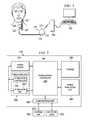
- FIG. 1illustrates an implantable medical device (IMD) 110 having a main body 112 comprising a can 121 with a connector 114 for connecting to leads 122 .
- the IMD 110is implanted in a patient's chest in a pocket or cavity formed by the implanting surgeon just below the skin, similar to the implantation procedure for a pacemaker pulse generator.
- a stimulating nerve electrode assembly 125preferably comprising an electrode pair, conductively couples to the distal end of an insulated and electrically conductive lead assembly 122 , which preferably comprises a pair of lead wires (one wire for each electrode of an electrode pair).
- Lead assembly 122is attached at its proximal end to the connector 114 on can 121 .
- the electrode assemblyis surgically coupled to a cranial nerve, such as a vagus nerve 127 in the patient's neck.
- the electrode assembly 125preferably comprises a bipolar stimulating electrode pair, such as the electrode pair described in U.S. Pat. No. 4,573,481, which is incorporated herein by reference. Persons of skill in the art will appreciate that many electrode designs could be used in the present disclosure.
- the two electrodesare preferably wrapped around the vagus nerve, and the electrode assembly 125 preferably is secured to the nerve 127 by a spiral anchoring tether such as that disclosed in U.S. Pat. No. 4,979,511, which is incorporated herein by reference.
- Lead assembly 122may be secured, while retaining the ability to flex with movement of the chest and neck, by a suture connection to nearby tissue.
- the IMD 110may be controlled or programmed with an external device 150 (e.g., a computer) and a programming wand 155 to facilitate radio frequency (RF) communication between the external device 150 and the IMD 110 .
- the wand 155 and softwarepermit noninvasive communication with the IMD 110 after the latter is implanted.
- the programming wand 155may be omitted to permit more convenient communication directly between the external device 150 and the IMD 110 .
- FIG. 2illustrates a block diagram of IMD 110 for performing neurostimulation in accordance with embodiments of the present disclosure.
- the IMD 110comprises a power source 210 , a power-source controller 220 , a stimulation controller 230 , a power regulation unit 240 , a stimulation unit 250 , a communication unit 260 and storage 280 .
- the stimulation controller 230 and stimulation unit 250together form stimulation logic 255 .
- Storage 280may be used for storing various program codes, starting data, and the like.
- the power source 210may comprise a battery, which may be rechargeable or non-rechargeable. Other power sources, such as capacitors, may also be used.
- the power source 210provides power for the operation of the IMD 110 , including electronic operations and stimulation bursts.
- Power source 210may be a lithium-thionyl chloride cell or a lithium/carbon monofluoride (LiCFx) cell.
- the terminals of the power source 210preferably electrically couple to an input side of the power-source controller 220 and the power regulation unit 240 .
- the power-source controller 220preferably comprises circuitry for controlling and monitoring the flow of electrical power to various electronic and stimulation-portions of the IMD 110 (such as the components 230 , 240 , 250 , 260 and 280 illustrated in FIG. 2 ). More particularly, the power-source controller 220 is capable of monitoring the power consumption or charge depletion of the IMD 110 , measuring the voltage across the power source 210 , and generating elective replacement and/or end-of-service signals.
- the communication unit 260facilitates communication between the IMD 110 and the external unit 150 , as shown.
- the external unit 150may be a device that is capable of programming various components and stimulation parameters of the IMD 110 .
- the external unit 150is a computer system capable of electronic communications, programming, and executing a data-acquisition program, preferably a handheld computer or PDA.
- the external unit 150preferably is controlled by a healthcare provider such as a physician in, for example, a doctor's office.
- the external unit 150may be used to download various parameters and program software into the IMD 110 for programming the operation of the IMD.
- the external unit 150may also receive and upload various status conditions and other data from the IMD 110 .
- the communication unit 260may comprise hardware, software, firmware or any combination thereof. Communications between the external unit 150 and the communication unit 260 may occur via a wireless or other type of communication, illustrated generally by line 275 in FIG. 2 .
- the power regulation unit 240is capable of regulating power delivered by the power source 210 to particular components of the IMD 110 according to their needs and functions.
- the power regulation unit 240may perform a voltage conversion to provide appropriate voltages and/or currents for the operation of the components.
- the power regulation unit 240may comprise hardware, software, firmware or any combination thereof.
- the communication unit 260is capable of providing transmission and reception of electronic signals to and from an external unit 150 .
- Stimulation controller 230defines the electrical stimulation pulses to be delivered as part of a burst to the nerve tissue according to parameters and waveforms that may be programmed into the IMD 110 using the external unit 150 or that may be pre-programmed into the controller 230 prior to or after implantation of the IMD 110 into the patient's body.
- the stimulation controller 230controls the operation of the stimulation unit 250 , which generates the stimulation pulses comprising a burst according to the parameters defined by the controller 230 and, in some embodiments, provides these pulses to the lead assembly 122 and electrode assembly 125 .
- Stimulation pulses provided by the IMD 110may vary widely across a range of parameters.
- the stimulation controller 230may comprise hardware, software, firmware or any combination thereof.
- the stimulation logic 255(stimulation controller 230 and stimulation unit 250 ) delivers stimulation bursts in response to certain events.
- the controller 230 and the unit 250may deliver a stimulation burst in response to detecting an impending or already-occurring seizure based on one or more of the patient's cardiac parameters (e.g., heart rate, rate of change of heart rate, heart rate variability, etc.).
- detection logic 270may be implemented anywhere on the patient's body to detect any type of event.
- the detection logic 270may be disposed in a location other than the patient's body to detect some other type of event independent of the patient's body (e.g., a request for a stimulation burst initiated by the patient).
- Detection logic 270may include a sensor (e.g., a sensor that detects user input, such as a tap or magnetic input apparatus).
- the detection logic 270Upon detecting an event, the detection logic 270 causes the stimulation controller 230 to activate the stimulation unit 250 in response to the detected event.
- One or more of the blocks 210 - 280may comprise hardware, firmware, software or any combination thereof.
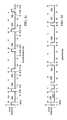
- FIGS. 3 a - 3 mshow waveforms that represent various ways in which the stimulation controller 230 may cause the stimulation unit 250 to deliver stimulation pulse bursts to the nerve to which the IMD 110 couples.
- the x-axisrepresents time and the y-axis represents electrical stimulation strength (e.g., current).
- the scope of this disclosureis not limited to the stimulation depicted in FIGS. 3 a - 3 m.
- FIG. 3 ashows a waveform that represents an example of programmed, open-loop stimulation pulse bursts.
- pulse burstsare delivered at regular intervals according to programmed parameters defining the duration of the bursts (i.e., on-time), the current, frequency and pulse width of each pulse within the burst, and the time between each burst (i.e., off-time).
- duration of the burstsi.e., on-time
- the current, frequency and pulse width of each pulse within the bursti.e., off-time
- time between each bursti.e., off-time
- An entire on-time/off-time cyclethus lasts for 15 seconds, with the pulses comprising the burst defined by one or more programmed parameters such as current, pulse width and frequency.
- the timingcan be varied as desired by programming different values for the on-time and the off-time.
- electrical stimulation dosing, battery usage and battery lifeare predictable because all stimulation bursts are delivered according to the programmed parameters in advance of delivery.
- FIG. 3 bshows a waveform that represents a scheduled, open-loop stimulation burst pattern to which a responsive, closed-loop stimulation burst has been added.
- Bursts 310 , 312 , 314 , 316 , 317 and 318are scheduled, open-loop stimulation bursts.
- burst 319is an unscheduled, closed-loop stimulation burst.
- Stimulation unit 250delivers the burst 319 as a result of some event, such as, for example, the detection of a particular cardiac change that signals an ongoing or impending seizure.
- the burst 319may be delivered as the result of manual instruction (e.g., the patient waves a magnet near the IMD 110 , thereby triggering delivery of the burst 319 ).
- the open-loop stimulation burstsare delivered as programmed, just as they were delivered as shown in FIG. 3 a .
- stimulation dosing, battery usage and battery lifeall are unpredictable, or poorly predictable.
- therapy for the patientmay be improved because closed-loop stimulation bursts are delivered as needed in response to, for example, an acute episodic event such as an epileptic seizure.
- FIG. 3 cshows an embodiment of the present invention in which a waveform that represents a programmed, open-loop stimulation burst pattern has been modified as the result of introducing an unprogrammed, closed-loop stimulation burst.
- Electrical stimulation bursts 320 , 322 , 324 , 326 and 328are programmed, open-loop bursts.
- Burst 329is a responsive, closed-loop burst.
- This closed-loop burst 329is delivered on-demand, in response to some event (e.g., detecting an impending seizure, manual stimulation, etc.).
- the IMD 110reschedules the delivery of the subsequent open-loop bursts 322 , 324 , 326 and 328 , to synchronize them with the responsive, closed-loop burst 329 .
- the open-loop burst 322was scheduled to be delivered 13 seconds after the end of open-loop burst 320
- burst 322is offset so that it is instead delivered 13 seconds after the end of closed-loop burst 329 .
- Subsequent programmed, open-loop burstsare then delivered after the off-time period following rescheduled burst 322 .
- burst 324is instead delivered 28 seconds after the end of closed-loop burst 329 (i.e., 13 seconds after the end of the rescheduled burst 322 ).
- Bursts 326 and 328are similarly synchronized to be applied 13 seconds after the previous (rescheduled) burst. In the embodiment of FIG.
- EITearly intervention time
- FIG. 3 dshows a waveform that represents another scheduled, open-loop stimulation burst pattern that has been modified as the result of introducing an unprogrammed, closed-loop stimulation burst.
- Electrical stimulation bursts 330 , 332 , 334 , 336 , 337 and 338are programmed, open-loop bursts.
- Burst 339is a responsive, closed-loop burst.
- open-loop burst 334was scheduled for delivery 13 seconds after the end of burst 332 , and so on.
- an unscheduled, closed-loop burst 339is delivered in response to an event.
- scheduling for the open-loop burstsis adjusted.
- the IMD 110skips delivery of burst 332 so that the programmed, open-loop burst 334 is the next burst to be delivered after the closed-loop burst 339 .
- burst 334is delivered at its programmed time, and is unaffected in terms of its timing, by the delivery of closed-loop burst 339 .
- the total electrical stimulation dosage delivered to the patientremains unchanged from the completely open-loop dosage, despite the periodic occurrence of responsive, closed-loop bursts.
- this techniqueincreases predictability of battery life determinations while providing the benefits of on-demand, closed-loop therapy.
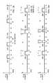
- FIGS. 3 e - 3 gshow other techniques in accordance with various embodiments.
- FIG. 3 eillustrates a waveform of another scheduled, open-loop stimulation burst pattern.
- FIG. 3 edepicts scheduled, open-loop bursts 340 , 342 , 344 , 346 and 348 .
- Each pulselasts for 2 seconds and is followed by an off-time that lasts for 13 seconds.
- pulse 342begins, and so forth.
- a responsive, closed-loop burst 344is delivered as a result of the IMD 110 detecting an event.
- the IMD 110delivers a responsive burst (i.e., burst 350 ) 5 seconds before the IMD 110 is scheduled to deliver a burst (i.e., programmed burst 342 , as shown in FIG. 3 e ).
- these 5 seconds of EITmay be added back into the schedule by interspersing them among one or more off cycles between programmed, open-loop bursts.
- FIG. 3 fshows one example of such interspersion.
- the next programmed burst 342may be resynchronized to begin after the programmed off-time has elapsed following the responsive burst 350 , as in FIG. 3 c .
- the EITi.e., the duration of time prior to the scheduled open-loop burst that the responsive, closed-loop burst was delivered
- the EITmay be recovered by adding all 5 seconds of the EIT back into the open-loop stimulation burst schedule immediately after the first open-loop burst 342 is administered after the programmed off-time following the closed-loop burst 350 (instead of its delivery as originally scheduled after the programmed off-time following the immediately preceding open-loop burst 340 ).
- the 5 seconds of EITmay be added to the off-time between bursts 350 and 342 or any other pair of bursts.
- the entire EIT of 5 secondsis added as a “lump sum” into the single off-time period following open-loop burst 342 .
- the EIT of 5 secondsmay be distributed in smaller quantities over a greater number of off-time cycles.
- 5/n seconds of the EITare added to each of n off-time cycles.
- This expressionassumes an even distribution of EIT over multiple off-time cycles but, in some embodiments, such distribution of EIT over off-time cycles may be adjusted so that it is uneven (e.g., of a total of 5 seconds EIT, 3 seconds may be added to one off cycle, while 2 seconds are added to another off cycle). It will be appreciated in view of the foregoing disclosure that various mathematical sequences (e.g., linearly increasing, exponentially increasing, random, etc.) may be employed to recover the EIT over a desired number of off-time cycles.
- the technique of FIG. 3 fgets the burst deliveries “back on schedule” faster than does the technique of FIG. 3 g .
- the 2.5 second installmentsmay be distributed among the off-times between bursts 350 and 344 or among off-times between any number of bursts following closed-loop burst 350 .
- FIGS. 3 h - 3 idepict another technique of compensating for reduced battery life associated with application of a responsive, closed-loop burst in accordance with various embodiments of the present invention. More particularly, in this technique, open-loop bursts that follow a closed-loop burst are shortened to compensate for the extra dosing (i.e., additional electrical charge applied to the target tissue) introduced by the closed-loop burst. This contrasts with the technique of “recovery of EIT” illustrated in FIGS. 3 f and 3 g by focusing on recovery of the extra electrical charge (as represented by individual pulses within a pulse burst) applied to the nerve in the responsive, closed-loop burst.
- FIG. 3 i(and FIG. 3 k , discussed hereafter, and other similar but non-illustrated embodiments) adjust a programmed, open-loop electrical signal to compensate for the occurrence of a responsive, closed-loop burst by reducing the amount of charge delivered to the nerve in one or more open-loop bursts following the closed-loop burst, until the total amount of charge delivered in the closed-loop burst has been completely “recovered” from the following closed-loop bursts.
- This concept of recovering closed-loop charge (CLC)is similar to that of the recovery of EIT discussed earlier (which is a specific embodiment of the more general concept of CLC recovery).
- the scheduled delivery of charge in a programmed, open-loop signalis reduced such that the charge delivered in a responsive, closed-loop burst merely substitutes for charge that would otherwise have been delivered as part of the programmed, open-loop signal.
- closed-loop burstsdo not increase the amount of charge applied to the nerve (and thus removed from the battery of the IMD) beyond that already programmed to occur under the programmed, open-loop signal.
- the delivery of a closed-loop burstsimply alters the timing of the delivery of charge to the nerve, not its rate over longer time periods.
- FIG. 3 hshows a dosing pattern including only programmed, open-loop pulse bursts.
- FIG. 3 hdepicts scheduled, open-loop bursts 360 , 362 , 364 , 366 , 368 and 370 .
- Each burstlasts for 2 seconds and is followed by an off-time that lasts for 13 seconds.
- pulse 362begins, and so forth.
- FIG. 3 iis similar to the pattern of FIG. 3 h but includes a responsive, closed-loop burst 382 .
- the closed-loop charge (CLC) introduced by the closed-loop burst 382is compensated for by reducing the electrical charge delivered to the target tissue during one or more subsequent open-loop bursts. For example, as shown, each of the open-loop bursts 384 , 386 and 388 is reduced in duration from 2 seconds to 4/3 seconds (i.e., in each of the subsequent bursts, the programmed on-time of 2 seconds is reduced by 2 ⁇ 3 seconds).
- CLC recoverymay be performed in a variety of ways (e.g., by reducing the durations of any suitable number of bursts by any appropriate amount, which may involve performing reductions on any of a variety of bursts (including closed-loop and open-loop bursts), etc.).
- FIG. 3 kdepicts another technique of compensating for reduced battery life associated with application of a responsive, closed-loop burst in accordance with various embodiments of the present invention.
- the duration of an off-time that precedes a burstdictates the duration of that burst.
- desired duty cyclesdefined as the ratio of on-time to the sum of on-time and off-time
- FIG. 3 jshows a dosing pattern including only scheduled, open-loop bursts.
- FIG. 3 jdepicts scheduled, open-loop bursts 400 , 402 , 404 and 406 .
- Each burstlasts for 4 seconds and is preceded by an off-time that lasts for 16 seconds.
- the next off-timebegins, and so forth.
- an on-time to off-time ratio of 1:4is achieved and maintained.
- FIG. 3 kshows a pattern similar to that of FIG. 3 j except it includes a responsive, closed-loop burst 412 .
- the next scheduled, open-loop burst 414is generated at its scheduled time, but the duration (i.e., on-time) of burst 414 is adjusted to be in proportion with the duration of the off-time between the closed-loop burst 412 and the open-loop burst 414 .
- the off-time between bursts 412 and 414is 4.8 seconds
- the desired on-time to off-time ratiois 1:4.
- the next open-loop pulse 416is delivered on schedule and is of the programmed duration. In the example of FIG. 3 k , only the durations of open-loop bursts are adjusted. The durations of closed-loop pulses are not scaled to meet any particular on-to-off-time ratio.
- FIG. 3 mshows a pattern similar to that shown in FIG. 3 l except it includes an unscheduled, closed-loop burst 432 .
- the duration (i.e., on-time) of closed-loop burst 432is not full-length (i.e., 4-seconds), however. Instead, the duration of closed-loop burst 432 is adjusted depending on the duration of the off-time that precedes it, much like that of burst 414 in FIG. 3 k .
- burst 432is 2 seconds long, followed by an off-time of 10 seconds that lasts until the next scheduled, open-loop burst 434 is applied.
- burst 434is delivered as programmed, the duration of burst 434 depends on the duration of the off-time that precedes it.
- the duration of the off-time preceding the burst 434is 10 seconds, so the burst 434 is 2 seconds long, thus maintaining the desired 1:5 ratio.
- the next off-timeis 20 seconds long and is followed by the regularly scheduled burst 436 , which is a full 4 seconds in duration.
- closed-loop burstsare delivered as a result of detecting some event.
- this eventis the detection of an impending or already-occurring seizure (e.g., detected by measuring one or more cardiac parameters).
- the timing of such an event detectionalso may be used to adjust the regularly scheduled open-loop dosing. For instance, if seizures tend to occur within some threshold amount of time from the ends of off-time periods but before the next scheduled burst, the off-times' duration may be reduced, thereby causing the open-loop cycles to be delivered more frequently.
- stimulation parameterse.g., frequency of the electrical pulses comprising a burst
- stimulationmay be suspended, reduced or discontinued altogether.
- an event(such as detection of an epileptic seizure) may be based upon an algorithm that processes a body parameter such as heart rate.
- event detection parametersmay be undesirably stringent, and may result in undesirably low amounts of stimulation.
- event detection parametersmay sometimes be undesirably lax, resulting in undesirably high amounts of stimulation.
- the IMD 110may be programmed to include minimum and maximum stimulation constraints. The IMD 110 may compare the actual amount of stimulation (i.e.
- the target tissuebased, for example, on the percentage of real time that stimulation is applied, or the amount of charge delivered to the nerve within one or more time frames, or the amount of time at which stimulation above a particular frequency is applied to the nerve
- the event detection (i.e., algorithm) parametersmay be modified (i.e., lowered) so that the actual amount of stimulation (in this case, rate of charge delivery) increases to meet or exceed the minimum stimulation constraint.
- the event detection parametersmay be modified (i.e., increased) so that the actual amount of stimulation decreases to meet or fall below the maximum stimulation constraint.
- the actual amount of stimulation(on a charge and/or time basis) may be dynamically regulated into a desired and/or programmed range.
- the techniques described hereinmay be implemented in various combinations. For example, the technique for reducing burst duration (depicted above in FIG. 3 i ) may be combined with the technique for increasing off-time duration (illustrated in FIG. 3 g ). This combination, in turn, may be combined with one or more additional techniques. Any and all combinations of the techniques described herein are included within the scope of this disclosure.
- programmed pulse burstsare adjusted by resynchronizing the programmed off-time to be measured from an unplanned, closed-loop burst rather than from the previously delivered open-loop burst.
- the off-time following a closed-loop burstis increased to cause the closed-loop burst to be considered as a substitute for the open-loop burst that would have been delivered next.
- FIGS. 3 f and 3 gdepict inserting additional off-time between one or more of open-loop bursts following a closed-loop burst to recover the early intervention time (EIT) associated with the closed-loop burst.
- EITearly intervention time
- CLCadditional charge
- the on-time of both the closed-loop and the next following open-loop burstare determined based upon their respective timing relative to the previous open-loop burst (in the case of the closed-loop burst) and the time of delivery of the closed-loop burst (in the case of the next open-loop burst), with the goal of maintaining a predetermined rate of electrical charge delivery to the target tissue.
- frequency and pulse-widthmay also be adjusted to compensate for the CLC delivered in an unprogrammed, closed-loop burst.
- the pulse width for some or all of the pulses of one or more open-loop bursts that follow an unprogrammed, closed-loop burstmay be reduced to recover the CLC delivered in the closed-loop burst.
- the programmed pulse width of an open-loop stimulation program for a patientmay be set at 250 microseconds.
- the pulse width of the next 5 subsequent open-loop burstsmay be reduced to 200 microseconds to recover the CLC applied in the closed-loop burst.
- open-loop frequencyis programmed at 30 Hz
- the frequency of the next 3 open-loop burstsmay be reduced to 20 Hz to recover the CLC applied during a closed-loop burst (assuming that the closed-loop burst has the same one-time, frequency, pulse width and current as a programmed open-loop burst).
- open-loop burstshave a programmed current of 2 milliamperes (mA)
- the charge delivered in a closed-loop burst having the same program parameters as the open-loop burstsmay be recovered by reducing the programmed current to 1 mA for the next two open-loop bursts following the closed-loop burst.
- slightly different adjustments to on-time, off-time, frequency, pulse width and/or currentmay be made to recover the charged applied in a closed-loop burst having different parameters (for example, a different on-time, frequency, pulse width, and/or current) than a programmed open-loop burst.
- one of more of the off-time, on-time, pulse width and current for one or more subsequent open loop burstsmay be adjusted to maintain the same rate of electrical charge delivery (i.e., coulombs of charge per unit time) as provided in programmed, open loop stimulation with no closed-loop stimulation.
- one or more of the on-time, pulse width, and current of the closed-loop burstmay also be adjusted based upon the time following the previous programmed, open-loop burst that the closed-loop burst is initiated.
- the foregoing techniquesmay be generally described by way of method 400 of FIG. 4 .
- the method 400begins by delivering one or more programmed, open-loop electrical bursts to a cranial nerve according to a first program (block 402 ).
- the cranial nervein at least some embodiments, is the vagus nerve.
- the first programpreferably is defined by a plurality of parameters programmed into the IMD 110 , the external device 150 , or some combination thereof.
- the method 400further comprises delivering a responsive, closed-loop electrical burst upon detecting an event or imminent event (e.g., a seizure) or on a user's manual command (block 404 ).
- the method 400further comprises temporarily adjusting at least one parameter defining the first program as a result of delivering the responsive, closed-loop electrical burst, thereby producing an adjusted program (block 406 ), where the adjusted program is characterized by restoring at least some portion of the battery life lost as a result of the delivery of the closed-loop burst.
- the adjusted programlike the first program, may be programmed in whole or part into the IMD 110 , the external device 150 , or some combination thereof.
- the program adjustmentmay employ any or all of the various techniques described herein and also may employ techniques not explicitly described herein.
- the method 400still further comprises delivering an electrical pulse or pulses to the cranial nerve according to the adjusted schedule (block 408 ), and restoring the original program parameters of the first program (block 410 ).
- an estimate of battery longevityis first made based on both an open-loop stimulation program and predicted closed-loop stimulation (based on the patient's personal disease history, detector performance capabilities, and/or one or more of a variety of other factors). Subsequently, in such embodiments, the rate of closed-loop stimulation that is actually provided by the IMD 110 when the IMD 110 is implanted and operating inside the patient's body (i.e., the rate of closed-loop stimulation “in real life”) is recorded and is used to adjust the estimate of battery longevity.
- the IMD 110may be programmed to deliver only open-loop therapy, but to record when closed-loop therapy would have been delivered had closed-loop therapy been enabled. This recorded information can then be used to estimate battery longevity. The estimation may be used to adjust IMD parameters in consideration of estimated battery longevity and, if desired, closed-loop stimulation may thereafter be enabled.
- longevity estimates of the IMD 110may be determined by first estimating longevity based on (1) programmed, open-loop stimulation and (2) estimates of responsive, closed-loop stimulation using the patient's personal disease history and the detection capabilities (e.g., sensitivity) of the detection logic 270 .
- the estimateis refined by monitoring the quantity of responsive, closed-loop stimulation bursts that are delivered by the IMD 110 after the IMD 110 is implanted in the patient's body.
- a log of such stimulation activitymay be recorded in storage 280 and later provided to the external unit 150 via the communication unit 260 .
- the logmay be provided in real-time to the external unit 150 via the communication unit 260 .
- the actual closed-loop stimulation datais used to refine the initial estimate regarding longevity of the IMD 110 .
- a different techniquemay be used to refine the initial estimate regarding longevity of the IMD 110 .
- the IMD 110is programmed to deliver not only scheduled, open-loop stimulations but is further programmed to record each instance at which the IMD 110 would have delivered an unscheduled, closed-loop stimulation had it been enabled to do so.
- These recorded datamay be provided to the external unit 150 in real-time or may be stored in storage 280 for subsequent transfer to the external unit 150 . In either case, the recorded data then are used to refine the initial estimate regarding longevity of the IMD 110 .
- Initial estimates and refinements theretopreferably are performed by the external unit 150 but also may be performed by the IMD 110 (e.g., by the power-source controller 220 , the power regulation unit 240 , stimulation logic 255 or any other suitable circuit logic). In some cases, portions of the initial estimates and/or refinements may be performed on the IMD 110 with the remainder of the estimates and/or refinements performed on the external unit 150 . Both the initial estimates and refined predictions are displayed or otherwise provided to an end-user of the external unit 150 (e.g., the patient's physician). The end-user may adjust IMD 110 closed-loop algorithm parameters (e.g., maximum and minimum stimulation thresholds at which a signal to initiate closed-loop stimulation is generated) in light of the estimated longevity. The end-user also may enable or disable responsive, closed-loop stimulations by the IMD 110 .
- IMD 110 closed-loop algorithm parameterse.g., maximum and minimum stimulation thresholds at which a signal to initiate closed-loop stimulation is generated
- FIG. 5shows a flow diagram of a method 500 in accordance with embodiments.
- the method 500begins by calculating an IMD longevity estimate using program parameters for open-loop electrical stimulation and predictions of the rate of responsive, closed-loop electrical stimulation (block 502 ).
- the method 500also comprises determining the actual rate at which closed-loop electrical bursts are requested to be delivered to a cranial nerve (e.g., the vagus nerve) (block 504 ).
- the action of block 504may occur in multiple ways.
- the action of block 504may include refining the initial calculation of block 502 based on actual closed-loop stimulation bursts that are delivered to the cranial nerve.
- closed-loop stimulationis not implemented, and the rate of detection of events that would have triggered closed-loop stimulation had it been enabled are used instead of actual closed-loop stimulation
- the method 500further comprises re-calculating the device longevity estimate based on the program parameters for open-loop stimulation and the determination of block 504 to produce a modified device longevity estimate (block 506 ).
- the method 500may, in some embodiments, further comprise modifying the operation of the device based on the modified device longevity calculation (block 508 ).
- the refined predictionsmay be provided to the end-user (e.g., a physician) so that the user may take appropriate action by modifying the operation of the IMD 110 as described above. For instance, IMD 110 parameters (e.g., maximum and minimum stimulation thresholds) may be adjusted, and closed-loop stimulation may be activated or deactivated.
Landscapes
- Health & Medical Sciences (AREA)
- Animal Behavior & Ethology (AREA)
- Public Health (AREA)
- Nuclear Medicine, Radiotherapy & Molecular Imaging (AREA)
- Radiology & Medical Imaging (AREA)
- Life Sciences & Earth Sciences (AREA)
- Engineering & Computer Science (AREA)
- General Health & Medical Sciences (AREA)
- Biomedical Technology (AREA)
- Veterinary Medicine (AREA)
- Heart & Thoracic Surgery (AREA)
- Neurology (AREA)
- Cardiology (AREA)
- Neurosurgery (AREA)
- Electrotherapy Devices (AREA)
Abstract
Description
Claims (20)
Priority Applications (3)
| Application Number | Priority Date | Filing Date | Title |
|---|---|---|---|
| US12/769,134US8874229B2 (en) | 2010-04-28 | 2010-04-28 | Delivering scheduled and unscheduled therapy without detriment to battery life or accuracy of longevity predictions |
| PCT/US2011/033447WO2011137029A1 (en) | 2010-04-28 | 2011-04-21 | Delivering scheduled and unscheduled therapy without detriment to battery life or accuracy of longevity predictions |
| US14/514,973US9421355B2 (en) | 2010-04-28 | 2014-10-15 | Delivering scheduled and unscheduled therapy without detriment to battery life or accuracy of longevity predictions |
Applications Claiming Priority (1)
| Application Number | Priority Date | Filing Date | Title |
|---|---|---|---|
| US12/769,134US8874229B2 (en) | 2010-04-28 | 2010-04-28 | Delivering scheduled and unscheduled therapy without detriment to battery life or accuracy of longevity predictions |
Related Child Applications (1)
| Application Number | Title | Priority Date | Filing Date |
|---|---|---|---|
| US14/514,973ContinuationUS9421355B2 (en) | 2010-04-28 | 2014-10-15 | Delivering scheduled and unscheduled therapy without detriment to battery life or accuracy of longevity predictions |
Publications (2)
| Publication Number | Publication Date |
|---|---|
| US20110270359A1 US20110270359A1 (en) | 2011-11-03 |
| US8874229B2true US8874229B2 (en) | 2014-10-28 |
Family
ID=44121020
Family Applications (2)
| Application Number | Title | Priority Date | Filing Date |
|---|---|---|---|
| US12/769,134Active2032-01-22US8874229B2 (en) | 2010-04-28 | 2010-04-28 | Delivering scheduled and unscheduled therapy without detriment to battery life or accuracy of longevity predictions |
| US14/514,973ActiveUS9421355B2 (en) | 2010-04-28 | 2014-10-15 | Delivering scheduled and unscheduled therapy without detriment to battery life or accuracy of longevity predictions |
Family Applications After (1)
| Application Number | Title | Priority Date | Filing Date |
|---|---|---|---|
| US14/514,973ActiveUS9421355B2 (en) | 2010-04-28 | 2014-10-15 | Delivering scheduled and unscheduled therapy without detriment to battery life or accuracy of longevity predictions |
Country Status (2)
| Country | Link |
|---|---|
| US (2) | US8874229B2 (en) |
| WO (1) | WO2011137029A1 (en) |
Families Citing this family (15)
| Publication number | Priority date | Publication date | Assignee | Title |
|---|---|---|---|---|
| US8255057B2 (en) | 2009-01-29 | 2012-08-28 | Nevro Corporation | Systems and methods for producing asynchronous neural responses to treat pain and/or other patient conditions |
| US9327121B2 (en) | 2011-09-08 | 2016-05-03 | Nevro Corporation | Selective high frequency spinal cord modulation for inhibiting pain, including cephalic and/or total body pain with reduced side effects, and associated systems and methods |
| ES2942684T3 (en) | 2009-04-22 | 2023-06-05 | Nevro Corp | Spinal cord modulation systems to induce paresthetic and anesthetic effects |
| WO2014164435A1 (en)* | 2013-03-11 | 2014-10-09 | Ohio State Innovation Foundation | Systems for treating anxiety and anxiety-associated disorders |
| EP2968918A1 (en) | 2013-03-11 | 2016-01-20 | The Ohio State Innovation Foundation | Systems for treating post-traumatic stress disorder |
| US9895539B1 (en) | 2013-06-10 | 2018-02-20 | Nevro Corp. | Methods and systems for disease treatment using electrical stimulation |
| US10149978B1 (en) | 2013-11-07 | 2018-12-11 | Nevro Corp. | Spinal cord modulation for inhibiting pain via short pulse width waveforms, and associated systems and methods |
| EP3111992B1 (en) | 2015-06-29 | 2018-08-01 | Sorin CRM SAS | Stimulation therapy system, in particular for vagus nerve stimulation, by implementing a state transition model operating at multiple space or time resolutions |
| EP3113033B1 (en) | 2015-06-29 | 2019-01-09 | Sorin CRM SAS | Stimulation therapy system, in particular of the vagus nerve, by implementing a state transition model |
| EP3111991B1 (en) | 2015-06-29 | 2020-01-29 | Sorin CRM SAS | Stimulation therapy system, in particular for vagus nerve stimulation, by implementing a state transition model that is self-adaptable in accordance with physical or physiological levels |
| EP3111990B1 (en) | 2015-06-29 | 2019-02-27 | Sorin CRM SAS | Stimulation therapy system, in particular for vagus nerve stimulation, by implementing a state transition model with prior learning |
| US11318310B1 (en) | 2015-10-26 | 2022-05-03 | Nevro Corp. | Neuromodulation for altering autonomic functions, and associated systems and methods |
| CN109310865B (en) | 2016-01-25 | 2022-09-13 | 内弗洛公司 | Electrostimulation treatment of congestive heart failure, and associated systems and methods |
| US20210387004A1 (en)* | 2018-10-23 | 2021-12-16 | Saluda Medical Pty Limited | Charge monitor |
| US11590352B2 (en) | 2019-01-29 | 2023-02-28 | Nevro Corp. | Ramped therapeutic signals for modulating inhibitory interneurons, and associated systems and methods |
Citations (105)
| Publication number | Priority date | Publication date | Assignee | Title |
|---|---|---|---|---|
| US3796221A (en) | 1971-07-07 | 1974-03-12 | N Hagfors | Apparatus for delivering electrical stimulation energy to body-implanted apparatus with signal-receiving means |
| US4324251A (en) | 1980-06-10 | 1982-04-13 | Pacesetter Systems, Inc. | Battery monitoring means and method for an implantable tissue stimulator |
| US4488555A (en) | 1982-12-13 | 1984-12-18 | Mieczyslaw Mirowski | Battery condition warning system for medical implant |
| US4556061A (en) | 1982-08-18 | 1985-12-03 | Cordis Corporation | Cardiac pacer with battery consumption monitor circuit |
| US4686990A (en) | 1985-10-02 | 1987-08-18 | Siemens Aktiengesellschaft | Battery test circuit for a heart pacemaker |
| US4702254A (en) | 1983-09-14 | 1987-10-27 | Jacob Zabara | Neurocybernetic prosthesis |
| US4715381A (en) | 1985-10-02 | 1987-12-29 | Siemens Aktiengesellschaft | Battery test circuit for a heart pacemaker |
| US4850356A (en) | 1980-08-08 | 1989-07-25 | Darox Corporation | Defibrillator electrode system |
| US4867164A (en) | 1983-09-14 | 1989-09-19 | Jacob Zabara | Neurocybernetic prosthesis |
| US4899750A (en) | 1988-04-19 | 1990-02-13 | Siemens-Pacesetter, Inc. | Lead impedance scanning system for pacemakers |
| US4964407A (en) | 1988-08-29 | 1990-10-23 | Intermedics, Inc. | Method and apparatus for assuring pacer programming is compatible with the lead |
| US5025807A (en) | 1983-09-14 | 1991-06-25 | Jacob Zabara | Neurocybernetic prosthesis |
| US5127404A (en) | 1990-01-22 | 1992-07-07 | Medtronic, Inc. | Telemetry format for implanted medical device |
| US5137020A (en) | 1990-11-29 | 1992-08-11 | Medtronic, Inc. | Battery impedance measurement apparatus |
| US5137021A (en) | 1990-11-29 | 1992-08-11 | Medtronic, Inc. | Lead current measurement circuit |
| US5146920A (en) | 1989-11-20 | 1992-09-15 | Sanyo Electric Co., Ltd. | Wireless low-frequency medical treatment device with pulse interruption based upon electrode contact with the body |
| US5154172A (en) | 1989-11-13 | 1992-10-13 | Cyberonics, Inc. | Constant current sources with programmable voltage source |
| US5179950A (en) | 1989-11-13 | 1993-01-19 | Cyberonics, Inc. | Implanted apparatus having micro processor controlled current and voltage sources with reduced voltage levels when not providing stimulation |
| US5188104A (en) | 1991-02-01 | 1993-02-23 | Cyberonics, Inc. | Treatment of eating disorders by nerve stimulation |
| US5193538A (en) | 1989-02-14 | 1993-03-16 | Siemens Aktiengesellschaft | In vivo implantable medical device with battery monitoring circuitry |
| US5201808A (en) | 1992-02-10 | 1993-04-13 | Telectronics Pacing Systems, Inc. | Minute volume rate-responsive pacemaker employing impedance sensing on a unipolar lead |
| US5201865A (en) | 1991-10-28 | 1993-04-13 | Medtronic, Inc. | Medical lead impedance measurement system |
| US5215086A (en) | 1991-05-03 | 1993-06-01 | Cyberonics, Inc. | Therapeutic treatment of migraine symptoms by stimulation |
| US5222494A (en) | 1991-07-31 | 1993-06-29 | Cyberonics, Inc. | Implantable tissue stimulator output stabilization system |
| US5231988A (en) | 1991-08-09 | 1993-08-03 | Cyberonics, Inc. | Treatment of endocrine disorders by nerve stimulation |
| US5263480A (en) | 1991-02-01 | 1993-11-23 | Cyberonics, Inc. | Treatment of eating disorders by nerve stimulation |
| US5269303A (en) | 1991-02-22 | 1993-12-14 | Cyberonics, Inc. | Treatment of dementia by nerve stimulation |
| US5299569A (en) | 1991-05-03 | 1994-04-05 | Cyberonics, Inc. | Treatment of neuropsychiatric disorders by nerve stimulation |
| US5330515A (en) | 1992-06-17 | 1994-07-19 | Cyberonics, Inc. | Treatment of pain by vagal afferent stimulation |
| US5335657A (en) | 1991-05-03 | 1994-08-09 | Cyberonics, Inc. | Therapeutic treatment of sleep disorder by nerve stimulation |
| US5352968A (en) | 1992-05-28 | 1994-10-04 | Apple Computer, Inc. | Battery charge state determination |
| US5352962A (en) | 1993-04-19 | 1994-10-04 | Sug Lithography Systems, Inc. | Brushless polyphase reduced force variation motor |
| US5372607A (en) | 1993-06-23 | 1994-12-13 | Medtronic, Inc. | Method and apparatus for monitoring pacemaker intervals |
| US5391193A (en) | 1993-02-05 | 1995-02-21 | Medtronic, Inc. | Method and apparatus for battery depletion monitoring |
| US5431692A (en) | 1993-08-02 | 1995-07-11 | Telectronics Pacing Systems, Inc. | Method and apparatus for testing compatibility of lead polarity and polarity programming of a cardiac stimulator |
| US5458624A (en) | 1993-10-06 | 1995-10-17 | Vitatron Medical, B.V. | Cardiac pacing system with improved end-of-life detector |
| US5496353A (en) | 1993-09-23 | 1996-03-05 | Grandjean; Pierre A. | End-of-life indication system for implantable pulse generator |
| US5507786A (en) | 1994-04-14 | 1996-04-16 | Pacesetter, Inc. | System and method for measuring and storing parametric data pertaining to operating characteristics of an implantable medical device |
| US5522865A (en) | 1989-09-22 | 1996-06-04 | Alfred E. Mann Foundation For Scientific Research | Voltage/current control system for a human tissue stimulator |
| US5534018A (en) | 1994-11-30 | 1996-07-09 | Medtronic, Inc. | Automatic lead recognition for implantable medical device |
| US5540734A (en) | 1994-09-28 | 1996-07-30 | Zabara; Jacob | Cranial nerve stimulation treatments using neurocybernetic prosthesis |
| US5540730A (en) | 1995-06-06 | 1996-07-30 | Cyberonics, Inc. | Treatment of motility disorders by nerve stimulation |
| US5549646A (en) | 1994-12-06 | 1996-08-27 | Pacesetter, Inc. | Periodic electrical lead intergrity testing system and method for implantable cardiac stimulating devices |
| US5571150A (en) | 1994-12-19 | 1996-11-05 | Cyberonics, Inc. | Treatment of patients in coma by nerve stimulation |
| US5620474A (en) | 1995-04-24 | 1997-04-15 | Vitatron Medical, B.V. | System and method for determining indicated pacemaker replacement time based upon battery impedance measurement |
| US5703469A (en) | 1995-06-05 | 1997-12-30 | Honda Giken Kogyo Kabushiki Kaisha | System for determining battery conditions |
| US5707400A (en) | 1995-09-19 | 1998-01-13 | Cyberonics, Inc. | Treating refractory hypertension by nerve stimulation |
| US5713936A (en) | 1995-11-08 | 1998-02-03 | Litronik Batterietechnologie Gmbh & Co. | Implantable medical device with end-of-life battery detection circuit |
| US5741307A (en) | 1997-01-21 | 1998-04-21 | Pacesetter, Inc. | Method for determining an ICD replacement time |
| US5741311A (en) | 1996-06-27 | 1998-04-21 | Medtronic, Inc. | Implantable medical device system with method for determining lead condition |
| US5755742A (en) | 1996-11-05 | 1998-05-26 | Medtronic, Inc. | Cardioversion/defibrillation lead impedance measurement system |
| US5769873A (en) | 1996-10-15 | 1998-06-23 | Pacesetter, Inc. | Meter for measuring battery charge delivered in an implantable device |
| US5814088A (en) | 1997-03-26 | 1998-09-29 | Sulzer Intermedics Inc. | Cardiac stimulator with lead failure detector and warning system |
| US5876425A (en) | 1989-09-22 | 1999-03-02 | Advanced Bionics Corporation | Power control loop for implantable tissue stimulator |
| US5891179A (en) | 1997-11-20 | 1999-04-06 | Paceseter, Inc. | Method and apparatus for monitoring and displaying lead impedance in real-time for an implantable medical device |
| US5897577A (en) | 1997-11-07 | 1999-04-27 | Medtronic, Inc. | Pacing lead impedance monitoring circuit and method |
| US5928272A (en) | 1998-05-02 | 1999-07-27 | Cyberonics, Inc. | Automatic activation of a neurostimulator device using a detection algorithm based on cardiac activity |
| US6016448A (en) | 1998-10-27 | 2000-01-18 | Medtronic, Inc. | Multilevel ERI for implantable medical devices |
| US6073050A (en) | 1998-11-10 | 2000-06-06 | Advanced Bionics Corporation | Efficient integrated RF telemetry transmitter for use with implantable device |
| US6108579A (en) | 1996-04-15 | 2000-08-22 | Pacesetter, Inc. | Battery monitoring apparatus and method for programmers of cardiac stimulating devices |
| US6148235A (en) | 1998-07-17 | 2000-11-14 | Vitatron Medical, B.V. | Implantable stimulator with battery status measurement |
| US6167309A (en) | 1997-09-15 | 2000-12-26 | Cardiac Pacemakers, Inc. | Method for monitoring end of life for battery |
| US6181969B1 (en) | 1998-06-26 | 2001-01-30 | Advanced Bionics Corporation | Programmable current output stimulus stage for implantable device |
| US6185461B1 (en) | 1998-07-01 | 2001-02-06 | Pacesetter, Inc. | System and method for verification of recommended replacement time indication in an implantable cardiac stimulation device |
| WO2001008749A1 (en) | 1999-07-31 | 2001-02-08 | Medtronic, Inc. | Device and method for determining the remaining battery life in an implantable neurological tissue stimulating device |
| US6212431B1 (en) | 1998-09-08 | 2001-04-03 | Advanced Bionics Corporation | Power transfer circuit for implanted devices |
| US20010034541A1 (en) | 1997-09-15 | 2001-10-25 | Cardiac Pacemakers, Inc. | Method for monitoring end of life for battery |
| US6317633B1 (en) | 1999-01-19 | 2001-11-13 | Medtronic, Inc. | Implantable lead functional status monitor and method |
| US6341236B1 (en) | 1999-04-30 | 2002-01-22 | Ivan Osorio | Vagal nerve stimulation techniques for treatment of epileptic seizures |
| US20020022866A1 (en) | 2000-08-17 | 2002-02-21 | Borkan William N. | Multichannel stimulator electronics and methods |
| US6400988B1 (en) | 2000-02-18 | 2002-06-04 | Pacesetter, Inc. | Implantable cardiac device having precision RRT indication |
| US6445951B1 (en) | 1999-10-12 | 2002-09-03 | Pacesetter, Inc. | Implantable cardiac stimulating device incorporating high frequency low amplitude lead impedance measurement |
| US6453198B1 (en) | 2000-04-28 | 2002-09-17 | Medtronic, Inc. | Power management for an implantable medical device |
| US6473644B1 (en) | 1999-10-13 | 2002-10-29 | Cyberonics, Inc. | Method to enhance cardiac capillary growth in heart failure patients |
| US6490486B1 (en) | 2000-04-27 | 2002-12-03 | Pacesetter, Inc. | Implantable cardiac stimulation device and method that monitors displacement of an implanted lead |
| US6490484B2 (en) | 2001-01-24 | 2002-12-03 | Cardiac Pacemakers, Inc. | Apparatus and method for estimating battery condition in implantable cardioverter/defibrillators |
| US20030074037A1 (en) | 2001-10-17 | 2003-04-17 | Rehabilicare, Inc. | Electrical nerve stimulation device |
| US6553263B1 (en) | 1999-07-30 | 2003-04-22 | Advanced Bionics Corporation | Implantable pulse generators using rechargeable zero-volt technology lithium-ion batteries |
| US6587719B1 (en) | 1999-07-01 | 2003-07-01 | Cyberonics, Inc. | Treatment of obesity by bilateral vagus nerve stimulation |
| US6609025B2 (en) | 2001-01-02 | 2003-08-19 | Cyberonics, Inc. | Treatment of obesity by bilateral sub-diaphragmatic nerve stimulation |
| US6622047B2 (en) | 2001-07-28 | 2003-09-16 | Cyberonics, Inc. | Treatment of neuropsychiatric disorders by near-diaphragmatic nerve stimulation |
| US6622041B2 (en) | 2001-08-21 | 2003-09-16 | Cyberonics, Inc. | Treatment of congestive heart failure and autonomic cardiovascular drive disorders |
| US6622038B2 (en) | 2001-07-28 | 2003-09-16 | Cyberonics, Inc. | Treatment of movement disorders by near-diaphragmatic nerve stimulation |
| US6620186B2 (en) | 2000-05-25 | 2003-09-16 | International Business Machines Corporation | Method and system for medical lead impedance test |
| US6648823B2 (en) | 2001-07-31 | 2003-11-18 | Medtronic, Inc. | Method and system of follow-up support for a medical device |
| US6658294B1 (en) | 2001-08-29 | 2003-12-02 | Pacesetter, Inc. | Implantable cardiac device having an impedance monitoring circuit and method |
| US6671552B2 (en) | 2001-10-02 | 2003-12-30 | Medtronic, Inc. | System and method for determining remaining battery life for an implantable medical device |
| US6687538B1 (en) | 2000-06-19 | 2004-02-03 | Medtronic, Inc. | Trial neuro stimulator with lead diagnostics |
| US6721600B2 (en) | 2000-01-19 | 2004-04-13 | Medtronic, Inc. | Implantable lead functional status monitor and method |
| US6745077B1 (en) | 2000-10-11 | 2004-06-01 | Advanced Bionics Corporation | Electronic impedance transformer for inductively-coupled load stabilization |
| US6748273B1 (en) | 1999-07-19 | 2004-06-08 | St. Jude Medical Ab | Method and circuit for determining the battery status in a medical implant |
| US6760624B2 (en) | 2001-12-03 | 2004-07-06 | Cardiac Pacemakers, Inc. | Method and apparatus for measuring lead impedance in an implantable cardiac rhythm management device |
| US6760625B1 (en) | 2001-10-11 | 2004-07-06 | Pacesetter, Inc. | Battery monitoring system for an implantable medical device |
| WO2004075982A1 (en) | 2003-02-21 | 2004-09-10 | Medtronic, Inc. | Implantable neurostimulator programming with battery longevity indication |
| US20040199146A1 (en) | 2003-04-07 | 2004-10-07 | Rogers Charles R. | System and method for monitoring power source longevity of an implantable medical device |
| US20050088145A1 (en) | 2003-10-23 | 2005-04-28 | Robert Loch | Battery charge indicator such as for an implantable medical device |
| US20050272280A1 (en) | 2001-10-22 | 2005-12-08 | Osypka Thomas P | Lead adaptor having low resistance conductors and/or encapsulated housing |
| US7174213B2 (en)* | 2000-04-05 | 2007-02-06 | Pless Benjamin D | Electrical stimulation strategies to reduce the incidence of seizures |
| US20070150019A1 (en) | 2005-12-15 | 2007-06-28 | Cardiac Pacemakers, Inc | Implantable medical device powered by rechargeable battery |
| US20070216366A1 (en) | 2006-03-15 | 2007-09-20 | Shoichi Inamine | Method for judging service life of primary battery |
| US20070255374A1 (en)* | 2006-04-28 | 2007-11-01 | Cyberonics, Inc. | Compensation reduction in tissue stimulation therapy |
| US20080097544A1 (en) | 2006-10-20 | 2008-04-24 | Rajesh Krishan Gandhi | Dynamic battery management in an implantable device |
| US7584000B2 (en)* | 2002-07-26 | 2009-09-01 | Advanced Neuromodulation Systems, Inc. | Method and system for energy conservation in implantable stimulation devices |
| US20100121591A1 (en) | 2008-11-13 | 2010-05-13 | Lockheed Martin Corporation | Method and apparatus that detects state of charge (soc) of a battery |
| US7751891B2 (en) | 2004-07-28 | 2010-07-06 | Cyberonics, Inc. | Power supply monitoring for an implantable device |
Family Cites Families (8)
| Publication number | Priority date | Publication date | Assignee | Title |
|---|---|---|---|---|
| US4573481A (en) | 1984-06-25 | 1986-03-04 | Huntington Institute Of Applied Research | Implantable electrode array |
| US4979511A (en) | 1989-11-03 | 1990-12-25 | Cyberonics, Inc. | Strain relief tether for implantable electrode |
| EP1583464B1 (en)* | 2002-10-15 | 2014-04-09 | Medtronic, Inc. | Clustering of recorded patient neurological activity to determine length of a neurological event |
| US20050131467A1 (en)* | 2003-11-02 | 2005-06-16 | Boveja Birinder R. | Method and apparatus for electrical stimulation therapy for at least one of atrial fibrillation, congestive heart failure, inappropriate sinus tachycardia, and refractory hypertension |
| US7801604B2 (en)* | 2006-08-29 | 2010-09-21 | Cardiac Pacemakers, Inc. | Controlled titration of neurostimulation therapy |
| US8150521B2 (en)* | 2007-03-15 | 2012-04-03 | Cvrx, Inc. | Methods and devices for controlling battery life in an implantable pulse generator |
| US7848812B2 (en)* | 2007-07-20 | 2010-12-07 | Cvrx, Inc. | Elective service indicator based on pulse count for implantable device |
| US9529972B2 (en)* | 2007-09-24 | 2016-12-27 | Medtronic, Inc. | Patient event indication |
- 2010
- 2010-04-28USUS12/769,134patent/US8874229B2/enactiveActive
- 2011
- 2011-04-21WOPCT/US2011/033447patent/WO2011137029A1/enactiveApplication Filing
- 2014
- 2014-10-15USUS14/514,973patent/US9421355B2/enactiveActive
Patent Citations (121)
| Publication number | Priority date | Publication date | Assignee | Title |
|---|---|---|---|---|
| US3796221A (en) | 1971-07-07 | 1974-03-12 | N Hagfors | Apparatus for delivering electrical stimulation energy to body-implanted apparatus with signal-receiving means |
| US4324251A (en) | 1980-06-10 | 1982-04-13 | Pacesetter Systems, Inc. | Battery monitoring means and method for an implantable tissue stimulator |
| US4850356A (en) | 1980-08-08 | 1989-07-25 | Darox Corporation | Defibrillator electrode system |
| US4556061A (en) | 1982-08-18 | 1985-12-03 | Cordis Corporation | Cardiac pacer with battery consumption monitor circuit |
| US4488555A (en) | 1982-12-13 | 1984-12-18 | Mieczyslaw Mirowski | Battery condition warning system for medical implant |
| US5025807A (en) | 1983-09-14 | 1991-06-25 | Jacob Zabara | Neurocybernetic prosthesis |
| US4702254A (en) | 1983-09-14 | 1987-10-27 | Jacob Zabara | Neurocybernetic prosthesis |
| US4867164A (en) | 1983-09-14 | 1989-09-19 | Jacob Zabara | Neurocybernetic prosthesis |
| US4686990A (en) | 1985-10-02 | 1987-08-18 | Siemens Aktiengesellschaft | Battery test circuit for a heart pacemaker |
| US4715381A (en) | 1985-10-02 | 1987-12-29 | Siemens Aktiengesellschaft | Battery test circuit for a heart pacemaker |
| US4899750A (en) | 1988-04-19 | 1990-02-13 | Siemens-Pacesetter, Inc. | Lead impedance scanning system for pacemakers |
| US4964407A (en) | 1988-08-29 | 1990-10-23 | Intermedics, Inc. | Method and apparatus for assuring pacer programming is compatible with the lead |
| US5193538A (en) | 1989-02-14 | 1993-03-16 | Siemens Aktiengesellschaft | In vivo implantable medical device with battery monitoring circuitry |
| US5522865A (en) | 1989-09-22 | 1996-06-04 | Alfred E. Mann Foundation For Scientific Research | Voltage/current control system for a human tissue stimulator |
| US5876425A (en) | 1989-09-22 | 1999-03-02 | Advanced Bionics Corporation | Power control loop for implantable tissue stimulator |
| US5154172A (en) | 1989-11-13 | 1992-10-13 | Cyberonics, Inc. | Constant current sources with programmable voltage source |
| US5179950A (en) | 1989-11-13 | 1993-01-19 | Cyberonics, Inc. | Implanted apparatus having micro processor controlled current and voltage sources with reduced voltage levels when not providing stimulation |
| US5146920A (en) | 1989-11-20 | 1992-09-15 | Sanyo Electric Co., Ltd. | Wireless low-frequency medical treatment device with pulse interruption based upon electrode contact with the body |
| US5127404A (en) | 1990-01-22 | 1992-07-07 | Medtronic, Inc. | Telemetry format for implanted medical device |
| US5344431A (en) | 1990-01-22 | 1994-09-06 | Medtronic, Inc. | Method and apparatus for determination of end-of-service for implantable devices |
| US5137020A (en) | 1990-11-29 | 1992-08-11 | Medtronic, Inc. | Battery impedance measurement apparatus |
| US5137021A (en) | 1990-11-29 | 1992-08-11 | Medtronic, Inc. | Lead current measurement circuit |
| US5188104A (en) | 1991-02-01 | 1993-02-23 | Cyberonics, Inc. | Treatment of eating disorders by nerve stimulation |
| US5263480A (en) | 1991-02-01 | 1993-11-23 | Cyberonics, Inc. | Treatment of eating disorders by nerve stimulation |
| US5269303A (en) | 1991-02-22 | 1993-12-14 | Cyberonics, Inc. | Treatment of dementia by nerve stimulation |
| US5335657A (en) | 1991-05-03 | 1994-08-09 | Cyberonics, Inc. | Therapeutic treatment of sleep disorder by nerve stimulation |
| US5299569A (en) | 1991-05-03 | 1994-04-05 | Cyberonics, Inc. | Treatment of neuropsychiatric disorders by nerve stimulation |
| US5215086A (en) | 1991-05-03 | 1993-06-01 | Cyberonics, Inc. | Therapeutic treatment of migraine symptoms by stimulation |
| US5222494A (en) | 1991-07-31 | 1993-06-29 | Cyberonics, Inc. | Implantable tissue stimulator output stabilization system |
| US5231988A (en) | 1991-08-09 | 1993-08-03 | Cyberonics, Inc. | Treatment of endocrine disorders by nerve stimulation |
| US5201865A (en) | 1991-10-28 | 1993-04-13 | Medtronic, Inc. | Medical lead impedance measurement system |
| US5201808A (en) | 1992-02-10 | 1993-04-13 | Telectronics Pacing Systems, Inc. | Minute volume rate-responsive pacemaker employing impedance sensing on a unipolar lead |
| US5352968A (en) | 1992-05-28 | 1994-10-04 | Apple Computer, Inc. | Battery charge state determination |
| US5330515A (en) | 1992-06-17 | 1994-07-19 | Cyberonics, Inc. | Treatment of pain by vagal afferent stimulation |
| US5391193A (en) | 1993-02-05 | 1995-02-21 | Medtronic, Inc. | Method and apparatus for battery depletion monitoring |
| US5352962A (en) | 1993-04-19 | 1994-10-04 | Sug Lithography Systems, Inc. | Brushless polyphase reduced force variation motor |
| US5372607A (en) | 1993-06-23 | 1994-12-13 | Medtronic, Inc. | Method and apparatus for monitoring pacemaker intervals |
| US5431692A (en) | 1993-08-02 | 1995-07-11 | Telectronics Pacing Systems, Inc. | Method and apparatus for testing compatibility of lead polarity and polarity programming of a cardiac stimulator |
| US5496353A (en) | 1993-09-23 | 1996-03-05 | Grandjean; Pierre A. | End-of-life indication system for implantable pulse generator |
| US5458624A (en) | 1993-10-06 | 1995-10-17 | Vitatron Medical, B.V. | Cardiac pacing system with improved end-of-life detector |
| US5507786A (en) | 1994-04-14 | 1996-04-16 | Pacesetter, Inc. | System and method for measuring and storing parametric data pertaining to operating characteristics of an implantable medical device |
| US5540734A (en) | 1994-09-28 | 1996-07-30 | Zabara; Jacob | Cranial nerve stimulation treatments using neurocybernetic prosthesis |
| US5534018A (en) | 1994-11-30 | 1996-07-09 | Medtronic, Inc. | Automatic lead recognition for implantable medical device |
| US5549646A (en) | 1994-12-06 | 1996-08-27 | Pacesetter, Inc. | Periodic electrical lead intergrity testing system and method for implantable cardiac stimulating devices |
| US5571150A (en) | 1994-12-19 | 1996-11-05 | Cyberonics, Inc. | Treatment of patients in coma by nerve stimulation |
| US5620474A (en) | 1995-04-24 | 1997-04-15 | Vitatron Medical, B.V. | System and method for determining indicated pacemaker replacement time based upon battery impedance measurement |
| US5703469A (en) | 1995-06-05 | 1997-12-30 | Honda Giken Kogyo Kabushiki Kaisha | System for determining battery conditions |
| US5540730A (en) | 1995-06-06 | 1996-07-30 | Cyberonics, Inc. | Treatment of motility disorders by nerve stimulation |
| US5707400A (en) | 1995-09-19 | 1998-01-13 | Cyberonics, Inc. | Treating refractory hypertension by nerve stimulation |
| US5713936A (en) | 1995-11-08 | 1998-02-03 | Litronik Batterietechnologie Gmbh & Co. | Implantable medical device with end-of-life battery detection circuit |
| US6108579A (en) | 1996-04-15 | 2000-08-22 | Pacesetter, Inc. | Battery monitoring apparatus and method for programmers of cardiac stimulating devices |
| US5741311A (en) | 1996-06-27 | 1998-04-21 | Medtronic, Inc. | Implantable medical device system with method for determining lead condition |
| US5769873A (en) | 1996-10-15 | 1998-06-23 | Pacesetter, Inc. | Meter for measuring battery charge delivered in an implantable device |
| US5755742A (en) | 1996-11-05 | 1998-05-26 | Medtronic, Inc. | Cardioversion/defibrillation lead impedance measurement system |
| US5925068A (en) | 1997-01-21 | 1999-07-20 | Pacesetter, Inc. | Method for determining an ICD replacment time |
| US5741307A (en) | 1997-01-21 | 1998-04-21 | Pacesetter, Inc. | Method for determining an ICD replacement time |
| US5814088A (en) | 1997-03-26 | 1998-09-29 | Sulzer Intermedics Inc. | Cardiac stimulator with lead failure detector and warning system |
| US6654640B2 (en) | 1997-09-15 | 2003-11-25 | Cardiac Pacemakers, Inc. | Method for monitoring end of life for battery |
| US20010034541A1 (en) | 1997-09-15 | 2001-10-25 | Cardiac Pacemakers, Inc. | Method for monitoring end of life for battery |
| US6167309A (en) | 1997-09-15 | 2000-12-26 | Cardiac Pacemakers, Inc. | Method for monitoring end of life for battery |
| US6631293B2 (en) | 1997-09-15 | 2003-10-07 | Cardiac Pacemakers, Inc. | Method for monitoring end of life for battery |
| US5897577A (en) | 1997-11-07 | 1999-04-27 | Medtronic, Inc. | Pacing lead impedance monitoring circuit and method |
| US5891179A (en) | 1997-11-20 | 1999-04-06 | Paceseter, Inc. | Method and apparatus for monitoring and displaying lead impedance in real-time for an implantable medical device |
| US5928272A (en) | 1998-05-02 | 1999-07-27 | Cyberonics, Inc. | Automatic activation of a neurostimulator device using a detection algorithm based on cardiac activity |
| US6181969B1 (en) | 1998-06-26 | 2001-01-30 | Advanced Bionics Corporation | Programmable current output stimulus stage for implantable device |
| US6185461B1 (en) | 1998-07-01 | 2001-02-06 | Pacesetter, Inc. | System and method for verification of recommended replacement time indication in an implantable cardiac stimulation device |
| US6148235A (en) | 1998-07-17 | 2000-11-14 | Vitatron Medical, B.V. | Implantable stimulator with battery status measurement |
| US6212431B1 (en) | 1998-09-08 | 2001-04-03 | Advanced Bionics Corporation | Power transfer circuit for implanted devices |
| US6016448A (en) | 1998-10-27 | 2000-01-18 | Medtronic, Inc. | Multilevel ERI for implantable medical devices |
| US6073050A (en) | 1998-11-10 | 2000-06-06 | Advanced Bionics Corporation | Efficient integrated RF telemetry transmitter for use with implantable device |
| US6317633B1 (en) | 1999-01-19 | 2001-11-13 | Medtronic, Inc. | Implantable lead functional status monitor and method |
| US6341236B1 (en) | 1999-04-30 | 2002-01-22 | Ivan Osorio | Vagal nerve stimulation techniques for treatment of epileptic seizures |
| US6671556B2 (en) | 1999-04-30 | 2003-12-30 | Ivan Osorio | Vagal nerve stimulation techniques for treatment of epileptic seizures |
| US6587727B2 (en) | 1999-04-30 | 2003-07-01 | Ivan Osorio | Vagal nerve stimulation techniques for treatment of epileptic seizures |
| US6587719B1 (en) | 1999-07-01 | 2003-07-01 | Cyberonics, Inc. | Treatment of obesity by bilateral vagus nerve stimulation |
| US6748273B1 (en) | 1999-07-19 | 2004-06-08 | St. Jude Medical Ab | Method and circuit for determining the battery status in a medical implant |
| US6553263B1 (en) | 1999-07-30 | 2003-04-22 | Advanced Bionics Corporation | Implantable pulse generators using rechargeable zero-volt technology lithium-ion batteries |
| WO2001008749A1 (en) | 1999-07-31 | 2001-02-08 | Medtronic, Inc. | Device and method for determining the remaining battery life in an implantable neurological tissue stimulating device |
| US6820019B1 (en) | 1999-07-31 | 2004-11-16 | Medtronic, Inc. | Device and method for determining and communicating the remaining life of a battery in an implantable neurological tissue stimulating device |
| US6445951B1 (en) | 1999-10-12 | 2002-09-03 | Pacesetter, Inc. | Implantable cardiac stimulating device incorporating high frequency low amplitude lead impedance measurement |
| US6473644B1 (en) | 1999-10-13 | 2002-10-29 | Cyberonics, Inc. | Method to enhance cardiac capillary growth in heart failure patients |
| US6721600B2 (en) | 2000-01-19 | 2004-04-13 | Medtronic, Inc. | Implantable lead functional status monitor and method |
| US6400988B1 (en) | 2000-02-18 | 2002-06-04 | Pacesetter, Inc. | Implantable cardiac device having precision RRT indication |
| US7174213B2 (en)* | 2000-04-05 | 2007-02-06 | Pless Benjamin D | Electrical stimulation strategies to reduce the incidence of seizures |
| US6490486B1 (en) | 2000-04-27 | 2002-12-03 | Pacesetter, Inc. | Implantable cardiac stimulation device and method that monitors displacement of an implanted lead |
| US6453198B1 (en) | 2000-04-28 | 2002-09-17 | Medtronic, Inc. | Power management for an implantable medical device |
| US6620186B2 (en) | 2000-05-25 | 2003-09-16 | International Business Machines Corporation | Method and system for medical lead impedance test |
| US6687538B1 (en) | 2000-06-19 | 2004-02-03 | Medtronic, Inc. | Trial neuro stimulator with lead diagnostics |
| US6662053B2 (en) | 2000-08-17 | 2003-12-09 | William N. Borkan | Multichannel stimulator electronics and methods |
| US20020022866A1 (en) | 2000-08-17 | 2002-02-21 | Borkan William N. | Multichannel stimulator electronics and methods |
| US6745077B1 (en) | 2000-10-11 | 2004-06-01 | Advanced Bionics Corporation | Electronic impedance transformer for inductively-coupled load stabilization |
| US6609025B2 (en) | 2001-01-02 | 2003-08-19 | Cyberonics, Inc. | Treatment of obesity by bilateral sub-diaphragmatic nerve stimulation |
| US6490484B2 (en) | 2001-01-24 | 2002-12-03 | Cardiac Pacemakers, Inc. | Apparatus and method for estimating battery condition in implantable cardioverter/defibrillators |
| US6622047B2 (en) | 2001-07-28 | 2003-09-16 | Cyberonics, Inc. | Treatment of neuropsychiatric disorders by near-diaphragmatic nerve stimulation |
| US6622038B2 (en) | 2001-07-28 | 2003-09-16 | Cyberonics, Inc. | Treatment of movement disorders by near-diaphragmatic nerve stimulation |
| US6648823B2 (en) | 2001-07-31 | 2003-11-18 | Medtronic, Inc. | Method and system of follow-up support for a medical device |
| US6622041B2 (en) | 2001-08-21 | 2003-09-16 | Cyberonics, Inc. | Treatment of congestive heart failure and autonomic cardiovascular drive disorders |
| US6658294B1 (en) | 2001-08-29 | 2003-12-02 | Pacesetter, Inc. | Implantable cardiac device having an impedance monitoring circuit and method |
| US20040039424A1 (en) | 2001-10-02 | 2004-02-26 | Merritt Donald R. | System and method for determining remaining battery life for an implantable medical device |
| US6671552B2 (en) | 2001-10-02 | 2003-12-30 | Medtronic, Inc. | System and method for determining remaining battery life for an implantable medical device |
| US6760625B1 (en) | 2001-10-11 | 2004-07-06 | Pacesetter, Inc. | Battery monitoring system for an implantable medical device |
| US6804557B1 (en) | 2001-10-11 | 2004-10-12 | Pacesetter, Inc. | Battery monitoring system for an implantable medical device |
| US7254444B2 (en) | 2001-10-17 | 2007-08-07 | Encore Medical Asset Corporation | Electrical nerve stimulation device |
| US20030074037A1 (en) | 2001-10-17 | 2003-04-17 | Rehabilicare, Inc. | Electrical nerve stimulation device |
| US20050272280A1 (en) | 2001-10-22 | 2005-12-08 | Osypka Thomas P | Lead adaptor having low resistance conductors and/or encapsulated housing |
| US7904161B2 (en) | 2001-10-22 | 2011-03-08 | Oscor Inc. | Lead adaptor having low resistance conductors and/or encapsulated housing |
| US6760624B2 (en) | 2001-12-03 | 2004-07-06 | Cardiac Pacemakers, Inc. | Method and apparatus for measuring lead impedance in an implantable cardiac rhythm management device |
| US7584000B2 (en)* | 2002-07-26 | 2009-09-01 | Advanced Neuromodulation Systems, Inc. | Method and system for energy conservation in implantable stimulation devices |
| US20050177206A1 (en) | 2003-02-21 | 2005-08-11 | North Richard B. | Implantable neurostimulator programming with battery longevity indication |
| WO2004075982A1 (en) | 2003-02-21 | 2004-09-10 | Medtronic, Inc. | Implantable neurostimulator programming with battery longevity indication |
| US7142923B2 (en) | 2003-02-21 | 2006-11-28 | Medtronic, Inc. | Implantable neurostimulator programming with battery longevity indication |
| US20040199146A1 (en) | 2003-04-07 | 2004-10-07 | Rogers Charles R. | System and method for monitoring power source longevity of an implantable medical device |
| US6901293B2 (en) | 2003-04-07 | 2005-05-31 | Medtronic, Inc. | System and method for monitoring power source longevity of an implantable medical device |
| US20050088145A1 (en) | 2003-10-23 | 2005-04-28 | Robert Loch | Battery charge indicator such as for an implantable medical device |
| US6940255B2 (en) | 2003-10-23 | 2005-09-06 | Cardiac Pacemakers, Inc. | Battery charge indicator such as for an implantable medical device |
| US7751891B2 (en) | 2004-07-28 | 2010-07-06 | Cyberonics, Inc. | Power supply monitoring for an implantable device |
| US20070150019A1 (en) | 2005-12-15 | 2007-06-28 | Cardiac Pacemakers, Inc | Implantable medical device powered by rechargeable battery |
| US20070216366A1 (en) | 2006-03-15 | 2007-09-20 | Shoichi Inamine | Method for judging service life of primary battery |
| US20070255374A1 (en)* | 2006-04-28 | 2007-11-01 | Cyberonics, Inc. | Compensation reduction in tissue stimulation therapy |
| US20080097544A1 (en) | 2006-10-20 | 2008-04-24 | Rajesh Krishan Gandhi | Dynamic battery management in an implantable device |
| US20100121591A1 (en) | 2008-11-13 | 2010-05-13 | Lockheed Martin Corporation | Method and apparatus that detects state of charge (soc) of a battery |
Non-Patent Citations (5)
| Title |
|---|
| International Application No. PCT/US2005/026514, Written Opinion dated Oct. 10, 2006, 4 pgs. |
| International Application No. PCT/US2007/000337, Written Opinion dated Jul. 27, 2008, 8 pgs. |
| International Patent Application No. PCT/US2011/061003, International Search Report and Written Opinion dated Jun. 28, 2012, 10 pages. |
| Terry, R.S., et al., "The Implantable Neurocybernetic Prosthesis System," Pacing and Clinical Electrophysiology, vol. 14, No. 1, (Jan. 1991), pp. 86-93. |
| Woodbury, J.W. et al., "Vagal Stimulation Reduces the Severity of Maximal Electroshock Seizures in Intact Rats: Use of Cuff Electrode for Stimulating and Recording," PACE, vol. 14, (Jan. 1991), pp. 94-107. |
Also Published As
| Publication number | Publication date |
|---|---|
| WO2011137029A1 (en) | 2011-11-03 |
| US20150032189A1 (en) | 2015-01-29 |
| US20110270359A1 (en) | 2011-11-03 |
| US9421355B2 (en) | 2016-08-23 |
Similar Documents
| Publication | Publication Date | Title |
|---|---|---|
| US9421355B2 (en) | Delivering scheduled and unscheduled therapy without detriment to battery life or accuracy of longevity predictions | |
| US9242110B2 (en) | Device longevity prediction for a device having variable energy consumption | |
| US10940317B2 (en) | System and method of adjusting the compliance voltage in a neuromodulation device | |
| US8694118B2 (en) | Variable output ramping for an implantable medical device | |
| US9878158B2 (en) | Neuromodulation system and method for reducing energy requirements using feedback | |
| US10328264B2 (en) | Method and apparatus for neurostimulation with prevention of neural accommodation | |
| US9724513B2 (en) | Methods to avoid frequency locking in a multi-channel neurostimulation system using pulse shifting | |
| US7974701B2 (en) | Dosing limitation for an implantable medical device | |
| US8543200B2 (en) | Methods to avoid frequency locking in a multi-channel neurostimulation system using pulse placement | |
| CN105163802A (en) | Neuromodulation system for providing multiple modulation patterns in a single channel | |
| US12042656B2 (en) | Bolus stimulation in a neurostimulation device particularly useful in providing sub-perception stimulation | |
| CN114845768A (en) | Neurostimulation devices that provide subsensory stimulation | |
| US20240342480A1 (en) | Bolus Stimulation in a Neurostimulation Device Particularly Useful in Providing Sub-Perception Stimulation |
Legal Events
| Date | Code | Title | Description |
|---|---|---|---|
| AS | Assignment | Owner name:CYBERONCS, INC., TEXAS Free format text:ASSIGNMENT OF ASSIGNORS INTEREST;ASSIGNOR:COLBORN, JOHN C.;REEL/FRAME:024302/0526 Effective date:20100428 | |
| STCF | Information on status: patent grant | Free format text:PATENTED CASE | |
| MAFP | Maintenance fee payment | Free format text:PAYMENT OF MAINTENANCE FEE, 4TH YEAR, LARGE ENTITY (ORIGINAL EVENT CODE: M1551) Year of fee payment:4 | |
| AS | Assignment | Owner name:ARES CAPITAL CORPORATION, AS COLLATERAL AGENT, NEW YORK Free format text:PATENT SECURITY AGREEMENT;ASSIGNOR:LIVANOVA USA, INC.;REEL/FRAME:053673/0675 Effective date:20200617 | |
| AS | Assignment | Owner name:ACF FINCO I LP, AS COLLATERAL AGENT, NEW YORK Free format text:PATENT SECURITY AGREEMENT;ASSIGNOR:LIVANOVA USA, INC.;REEL/FRAME:054881/0784 Effective date:20201230 | |
| AS | Assignment | Owner name:LIVANOVA USA, INC., TEXAS Free format text:RELEASE BY SECURED PARTY;ASSIGNOR:ARES CAPITAL CORPORATION, AS AGENT FOR THE LENDERS;REEL/FRAME:057189/0001 Effective date:20210812 Owner name:GOLDMAN SACHS BANK USA, AS COLLATERAL AGENT, NEW YORK Free format text:SECURITY INTEREST;ASSIGNOR:LIVANOVA USA, INC.;REEL/FRAME:057188/0001 Effective date:20210813 | |
| AS | Assignment | Owner name:LIVANOVA USA, INC., TEXAS Free format text:RELEASE BY SECURED PARTY;ASSIGNOR:ACF FINCO I LP;REEL/FRAME:057552/0378 Effective date:20210812 | |
| MAFP | Maintenance fee payment | Free format text:PAYMENT OF MAINTENANCE FEE, 8TH YEAR, LARGE ENTITY (ORIGINAL EVENT CODE: M1552); ENTITY STATUS OF PATENT OWNER: LARGE ENTITY Year of fee payment:8 |