US8873926B2 - Fiber optic enclosures employing clamping assemblies for strain relief of cables, and related assemblies and methods - Google Patents
Fiber optic enclosures employing clamping assemblies for strain relief of cables, and related assemblies and methodsDownload PDFInfo
- Publication number
- US8873926B2 US8873926B2US13/456,755US201213456755AUS8873926B2US 8873926 B2US8873926 B2US 8873926B2US 201213456755 AUS201213456755 AUS 201213456755AUS 8873926 B2US8873926 B2US 8873926B2
- Authority
- US
- United States
- Prior art keywords
- fiber optic
- optic cables
- cable fitting
- elongated member
- disposed
- Prior art date
- Legal status (The legal status is an assumption and is not a legal conclusion. Google has not performed a legal analysis and makes no representation as to the accuracy of the status listed.)
- Expired - Fee Related, expires
Links
Images


Classifications
- G—PHYSICS
- G02—OPTICS
- G02B—OPTICAL ELEMENTS, SYSTEMS OR APPARATUS
- G02B6/00—Light guides; Structural details of arrangements comprising light guides and other optical elements, e.g. couplings
- G02B6/44—Mechanical structures for providing tensile strength and external protection for fibres, e.g. optical transmission cables
- G02B6/4401—Optical cables
- G02B6/4415—Cables for special applications
- G02B6/4427—Pressure resistant cables, e.g. undersea cables
- G02B6/4428—Penetrator systems in pressure-resistant devices
- G—PHYSICS
- G02—OPTICS
- G02B—OPTICAL ELEMENTS, SYSTEMS OR APPARATUS
- G02B6/00—Light guides; Structural details of arrangements comprising light guides and other optical elements, e.g. couplings
- G02B6/24—Coupling light guides
- G02B6/42—Coupling light guides with opto-electronic elements
- G02B6/4201—Packages, e.g. shape, construction, internal or external details
- G02B6/4248—Feed-through connections for the hermetical passage of fibres through a package wall
- G—PHYSICS
- G02—OPTICS
- G02B—OPTICAL ELEMENTS, SYSTEMS OR APPARATUS
- G02B6/00—Light guides; Structural details of arrangements comprising light guides and other optical elements, e.g. couplings
- G02B6/44—Mechanical structures for providing tensile strength and external protection for fibres, e.g. optical transmission cables
- G02B6/4439—Auxiliary devices
- G02B6/4471—Terminating devices ; Cable clamps
- G02B6/44765—Terminating devices ; Cable clamps with means for strain-relieving to exterior cable layers
- G—PHYSICS
- G02—OPTICS
- G02B—OPTICAL ELEMENTS, SYSTEMS OR APPARATUS
- G02B6/00—Light guides; Structural details of arrangements comprising light guides and other optical elements, e.g. couplings
- G02B6/44—Mechanical structures for providing tensile strength and external protection for fibres, e.g. optical transmission cables
- G02B6/4439—Auxiliary devices
- G02B6/4471—Terminating devices ; Cable clamps
- G02B6/44775—Cable seals e.g. feed-through
- Y—GENERAL TAGGING OF NEW TECHNOLOGICAL DEVELOPMENTS; GENERAL TAGGING OF CROSS-SECTIONAL TECHNOLOGIES SPANNING OVER SEVERAL SECTIONS OF THE IPC; TECHNICAL SUBJECTS COVERED BY FORMER USPC CROSS-REFERENCE ART COLLECTIONS [XRACs] AND DIGESTS
- Y10—TECHNICAL SUBJECTS COVERED BY FORMER USPC
- Y10T—TECHNICAL SUBJECTS COVERED BY FORMER US CLASSIFICATION
- Y10T29/00—Metal working
- Y10T29/49—Method of mechanical manufacture
- Y10T29/49826—Assembling or joining
Definitions
- the technology of the disclosurerelates to fiber optic equipment, such as local convergence points (LCPs) and fiber distribution terminals (FDTs), and strain relief of fiber optic cables disposed therein which provide fiber optic connections to subscribers.
- LCPslocal convergence points
- FDTsfiber distribution terminals
- FIG. 1illustrates an exemplary fiber optic network 10 .
- the fiber optic network 10 in this exampleis a passive optical network (PON).
- PONis a point-to-multipoint FTTx network architecture to enable an optical fiber to serve multiple premises.
- a PON configurationgenerally reduces the amount of optical fiber and central office equipment as compared with point-to-point optical network architectures.
- the fiber optic network 10 in FIG. 1provides optical signals from switching points 12 over a distribution network 13 comprised of fiber optic feeder cables 14 .
- the switching points 12include optical line terminals (OLTs) or forward lasers/return receivers 15 that convert electrical signals to and from optical signals.
- the optical signalsmay then be carried over the fiber optic feeder cables 14 to local convergence points (LCPs) 16 .
- LCPs 16serve as consolidation points for splicing and making cross-connections and interconnections, as well as providing locations for optical couplers and splitters.
- the optical couplers and splitters in the LCPs 16enable a single optical fiber to serve multiple subscriber premises 20 .
- Fiber optic cables 18exit the LCPs 16 to carry optical signals between the fiber optic network 10 and the subscriber premises 20 .
- Typical subscriber premises 20include single-dwelling units (SDU), multi-dwelling units (MDU), businesses, and/or other facilities or buildings. End subscribers in the subscriber premises 20 may contain network devices configured to receive electrical signals as opposed to optical signals.
- optical network terminals (ONTs) and/or optical network units (ONUs) 21may be provided at the subscriber premises 20 to convert optical signals received over the fiber optic cables 18 to electronic signals.
- LCPs 16are typically configured to service multiple premises 20
- the fiber optic cables 18 leaving the LCPs 16are typically run to one or more intermediate fiber distribution terminals (FDTs) 22 .
- FDTs 22facilitate FTTx applications by providing network access points to the fiber optic network 10 to groupings of subscriber premises 20 .
- Optical interconnections to the subscriber premises 20are typically provided via indoor/outdoor drop cables 24 that are optically interconnected with the fiber optic cables 18 within the FDTs 22 .
- the FDTs 22may also provide a consolidated location for technicians or other installation personnel to make and protect splices and/or connections between the drop cables 24 and the fiber optic cables 18 as opposed to making splices and/or connections in sporadic locations.
- a fiber optic enclosuremay be part of a fiber optic terminal that may serve as a LCP 16 or FDT 22 in the fiber optic network 10 of FIG. 1 .
- a cable fitting assemblymay be attached around an opening of a wall of the fiber optic enclosure. The opening and cable fitting assembly provides a passageway for one or more fiber optic cables to travel between an outside and an inside of the fiber optic enclosure. Once outside, the fiber optic cables may be routed to the subscriber premises 20 , for example, to support the multi-dwelling units.
- the fiber optic cables exiting a fiber optic terminalmay need strain relief as optical fiber movement may damage the cable or cause signal attenuation.
- Conventional fiber optic terminalshave at least one strain relief mechanism inside the fiber optic enclosure to relieve strain in the separate fiber optic cables.
- Conventional mechanisms providing strain reliefoccupy valuable space in the fiber optic enclosure that could be used for additional fiber optic equipment.
- Embodiments disclosed hereininclude fiber optic enclosures employing clamping assemblies for strain relief of cables, and related assemblies and methods.
- the fiber optic enclosuresmay be part of a fiber optic terminal in a fiber optic network.
- the fiber optic enclosuresmay include openings in the walls of the fiber optic enclosure.
- a cable fitting assemblymay be attached to a portion of the wall around an opening to form a passageway for fiber optic cables to enter the fiber optic enclosure.
- An elongated membermay be used to guide the fiber optic cables through the passageway.
- the elongated membermay have a first end and second end.
- the elongated membermay include a clamping assembly at the first end to provide strain relief to the fiber optic cables by clamping strength members of the fiber optic cables.
- an elongated memberfor sealing off an opening located through an enclosure wall of a fiber optic enclosure.
- the fiber optic enclosuremay have a plurality of fiber optic cables disposed therethrough.
- the elongated membermay include a first end and a second end disposed opposite the first end along a longitudinal axis. The second end may be configured to guide a plurality of fiber optic cables into the opening of the enclosure.
- the elongated membermay also include a strain relief portion disposed at the first end.
- the strain relief portionmay include a plurality of recesses forming a plurality of openings. The plurality of recesses may be configured to each receive one of the plurality of fiber optic cables.
- Each of the plurality of recessesmay be separated by one of a plurality of external surfaces and disposed parallel to the longitudinal axis.
- the elongated membermay also include a clamping assembly.
- the clamping assemblymay be configured to clamp strength members of the plurality of fiber optic cables. This embodiment may provide strain relief to the fiber optic cables through the strength members and thereby may reduce damage to the fiber optic cables.
- a cable fitting assemblyfor an opening of a fiber optic enclosure.
- the cable fitting assemblymay include a cable fitting and an elongated member.
- the cable fitting assemblymay include an elongated cable fitting body including a first cable fitting end.
- the first cable fitting endmay comprise a first threaded portion.
- the first cable fitting endmay also comprise a second cable fitting end opposite the first cable fitting end.
- the first cable fitting endmay also include an orifice disposed therethrough from the first cable fitting end to the second cable fitting end.
- the orificemay be configured to receive a plurality of fiber optic cables.
- the first cable fitting endmay also include a cable fitting base that may be disposed between a first fitting end and a second fitting end.
- the cable fitting basemay comprise a base wall surface configured to form a contact area on a surface around an orifice of an enclosure wall.
- the cable fitting basemay also include a clamping mechanism.
- the cable fitting basemay also include a locknut including a threaded orifice and locknut bushing surface.
- the locknutmay be configured to be removeably attached to the first cable fitting end and may be configured to pull the base wall surface against the contact area.
- the elongated membermay include a first end and a second end. The first end may be disposed within the orifice of the elongated cable fitting body. The first end may also be opposite a second end along a longitudinal axis.
- the elongated membermay also include a strain relief portion disposed at the first end.
- the strain relief portionmay include a plurality of recesses forming a plurality of openings that are configured to each receive one of the plurality of fiber optic cables. Each of the plurality of recesses may be separated by one of a plurality of external surfaces and disposed parallel to the longitudinal axis.
- the elongated membermay also include a clamping assembly disposed at the first end.
- the clamping assemblymay be configured to clamp strength members of the plurality of fiber optic cables. This embodiment may provide strain relief to the plurality of fiber optic cables exiting through the opening of the fiber optic enclosure and thereby may reduce signal attenuation for signals traveling over the plurality of fiber optic cables.
- a methodfor installing a cable fitting assembly with a plurality of fiber optic cables into an opening of a fiber optic enclosure.
- This methodmay include inserting a first cable fitting end of an elongated cable fitting body through an opening of a fiber optic enclosure and securing the first cable fitting end to the fiber optic enclosure with a locknut.
- the methodmay also include inserting an end of the plurality of fiber optic cables through an orifice of the elongated cable fitting body.
- the methodmay also include receiving a threaded bushing through a bushing opening and into a bushing bore disposed at a first end of an elongated member.
- the methodmay include stripping the plurality of fiber optic cables from the end of the fiber optic cables to a transition point and separating strength members of the plurality of fiber optic cables from optical fibers of the plurality of fiber optic cables.
- the methodmay also include creating a strength member gap.
- the methodmay also include receiving the plurality of fiber optic cables through a plurality of openings into a plurality of recesses in a strain relief portion disposed at the first end of the elongated member. Each of the plurality of recesses may be separated by one of a plurality of external surfaces and disposed parallel to the longitudinal axis.
- the methodmay also include engaging a clamping assembly. This embodiment may provide an efficient manner to provide strain relief for the plurality of fiber optic cables installed into the opening of the fiber optic enclosure.
- FIG. 1illustrates an exemplary passive optical network (PON) in the prior art including an exemplary multi-dwelling unit (MDU) that includes optical network terminals (ONTs) and optical network units (ONUs) for converting electrical signals to optical signals, and vice versa, and fiber optic terminals for carrying optical signals over a fiber optic network;
- MDUmulti-dwelling unit
- ONTsoptical network terminals
- ONUsoptical network units
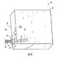
- FIG. 2illustrates an exemplary fiber optic terminal that may be employed with a cable fitting including an exemplary elongated member
- FIG. 3Ais a side view of an exemplary elongated member for providing sealing and/or strain relief for multiple fiber optic cables disposed through an opening of a fiber optic terminal;
- FIG. 3Bis a cross-section of a strain relief portion of the elongated member of FIG. 3A ;
- FIG. 3Cis a cross-section of a sealing portion of the elongated member of FIG. 3A ;
- FIG. 3Dis a cross-section of an intermediate portion of the elongated member of FIG. 3A ;
- FIG. 4Bis a partial cutaway side view of the cable fitting assembly containing the elongated member of FIG. 4A ;
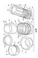
- FIG. 4Dis an exploded perspective view of the cable fitting assembly of FIG. 4A ;
- FIG. 5is a partial cross-section of the cable fitting assembly of FIG. 4A showing the sealing ring, plurality of fiber optic cables, and gap between (before the compression cap is attached);
- FIG. 6Ais a partial cross-section of the cable fitting assembly of FIG. 4A showing a multi-component cylindrical surface
- FIG. 6Bis a partial cross-section of the cable fitting assembly of FIG. 4A showing an alternative embodiment to the multi-component cylindrical surface
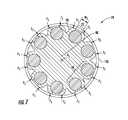
- FIG. 7is a partial cross-section of the cable fitting assembly of FIG. 4A showing the strain relief portion, the plurality of fiber optic cables, and plurality of inward-facing forces F 1 ;
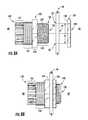
- FIG. 8Ais a side view showing an elongated cable fitting body and a locknut of FIG. 4A prior to attachment to a wall of a fiber optic enclosure (or terminal);
- FIG. 8Bis a side view showing an elongated cable fitting body and a locknut of FIG. 4A after attachment to the wall of the fiber optic enclosure (or terminal);
- FIG. 10is a side view showing the plurality of fiber optic cables of FIG. 4A being inserted through the elongated cable fitting body of FIG. 3A ;
- FIG. 11is a side view showing the plurality of fiber optic cables being received into the elongated member of FIG. 4A ;
- FIG. 13is a perspective view of a second exemplary embodiment of an elongated member without a second embodiment of a sealing portion attached;
- FIG. 14is a perspective view of the elongated member of FIG. 13 with the second embodiment of the sealing portion attached;
- FIG. 15is a perspective view of a third exemplary embodiment of an elongated member formed as an integrated body
- FIG. 16depicts an exemplary MDU that includes fiber optic terminals that include local convergence points (LCPs) and fiber distribution terminals (FDTs) providing connectivity of end subscribers to the fiber optic network using the elongated member of the cable fitting assembly depicted in FIG. 4A ;
- LCPslocal convergence points
- FDTsfiber distribution terminals
- FIGS. 17A and 17Bare a side view and a partial side view, respectively, of another embodiment of a cable fitting assembly
- FIG. 17Cis an exploded side view of the cable fitting assembly of FIGS. 17A and 17B ;
- FIGS. 18A through 18Dare a side view, a front view, a back view, and a cutaway view, respectively, of a threaded bushing of the cable fitting assembly of FIGS. 17A and 17B ;
- FIG. 20Ais a side view of an unstripped fiber optic cable
- FIG. 20Bis a side view of the fiber optic cable of FIG. 20A after being stripped as utilized with the cable fitting assembly of FIGS. 17A and 17B ;
- FIG. 21is a block diagram of an exemplary process for installing the cable fitting assembly of FIGS. 17A and 17B with at least one of the fiber optic cable of FIG. 20B into an opening of a fiber optic enclosure;
- FIG. 22Ais a side view of an elongated member of the cable fitting assembly of FIGS. 17A and 17B with a threaded bushing detached;
- FIG. 22Bis a front side view of the elongated member of FIG. 22A ;
- FIG. 22Cis a partial cutaway view of the threaded bushing received by the elongated member of FIG. 22A ;
- FIG. 23is a side view of the elongated member of FIG. 22C adjacent to a collar and a fastener;
- FIG. 24is a side view of the elongated member of FIG. 23 with the fastener in communication with the threaded bushing;
- FIGS. 25A and 25Bare a side view and a longitudinal side view, respectively, of the elongated member of FIG. 24 with a strength member wrapped around a clamping assembly;
- FIGS. 26A and 26Bare a side view and a longitudinal side view, respectively, of the elongated member of FIGS. 25A and 25B with a second strength member wrapped around the clamping assembly;
- FIG. 27is a perspective view of the elongated member of FIGS. 26A and 26B with multiple strength members wrapped around the clamping assembly;
- FIG. 28is a perspective view of the elongated member of FIG. 27 received into an elongated cable fitting body
- FIG. 29is a perspective view of the elongated member of FIG. 28 with a torque T being applied to the fastener to engage the clamping assembly.
- Embodiments disclosed hereininclude fiber optic enclosures employing clamping assemblies for strain relief cables, and related assemblies and methods.
- the fiber optic enclosuresmay be part of a fiber optic terminal in a fiber optic network.
- the fiber optic enclosuresmay include openings in the walls of the fiber optic enclosure.
- a cable fitting assemblymay be attached to a portion of the wall around an opening to form a passageway for fiber optic cables to enter the fiber optic enclosure.
- An elongated membermay be used to guide the fiber optic cables through the passageway.
- the elongated membermay have a first end and second end.
- the elongated membermay include a clamping assembly at the first end to provide strain relief to the fiber optic cables by clamping strength members of the fiber optic cables.
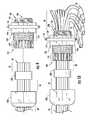
- FIG. 2shows a fiber optic enclosure 29 as part of a fiber optic terminal 30 .
- the fiber optic terminal 30may serve as a local convergence point (LCP) or a fiber optic distribution terminal (FDT) in a fiber optic network, as non-limiting examples.
- a cable fitting assembly 28may be attached to a contact surface 52 around an opening 54 of a wall 56 of the fiber optic enclosure 29 .
- the cable fitting assembly 28may include an elongated member 26 (discussed later) to provide strain relief and/or sealing against contamination.
- the opening 54provides a passageway for a plurality of fiber optic cables 58 to travel between an outside 60 and an inside 62 of the fiber optic enclosure 29 .
- the opening 54may be made during initial manufacturing or later during installation by removing “knockout” material by, for example, cutting or applying force.
- the fiber optic terminals 30provide convenient access points in a telecommunications or data network for a field technician to install and reconfigure optical fiber connections between network-side and subscriber-side fiber optic cables.
- the fiber optic terminals 30are configured to allow one or more optical fibers provided in one or more network-side or upstream fiber optic cables, for example feeder cables, to be easily and readily interconnected with one or more optical fibers in one or more subscriber-side or downstream fiber optic cables, for example drop cables.
- subscriber-sideit is meant that optical fiber, fiber optic cable, or optical connection, as the case may be, is provided anywhere between the end subscriber and the fiber optic terminals 30 .
- a subscriber-side fiber optic cable, optical fiber, or optical connectionmay be provided directly to an end subscriber or may be provided to one or more intermediate optical terminals or components before reaching an end subscriber.
- network-sideit is meant that the optical fiber, fiber optic cable, or optical connection, as the case may be, is provided between a fiber optic network, central switching point, central office, head end, or the like and the fiber optic terminals 30 .
- the fiber optic terminals 29 with a fiber optic cable exiting an openingare relatively straightforward to seal.
- An opening 54may be created in the outer wall 56 of the fiber optic terminal 29 consistent with a standard fiber optic cable size and cable fittings that are commercially available.
- the cable fittingmay be configured to attach to the outer wall 56 and through the opening 54 , and clamp a circular seal ring around the outer jacket of the fiber optic cable.
- Multiple optical fibersmay be “broken-out” from the outer jacket at a fiber optic terminal 30 closer to a group of the subscriber premises 20 , so that they may travel to separately to each of the subscriber premises 20 .
- each of the loose fiber optic cablescan be inserted through separate longitudinal holes disposed inside a flexible cylinder member.
- the flexible cylinder membercan be inserted into the cable fitting assembly 28 to facilitate providing an outer surface to create a seal.
- the inner diameters of the longitudinal holesare sized to allow the fiber optic cables to fit therethrough without gaps that would be incompatible with sealing.
- cables that are pre-connectorizedcannot be disposed through the longitudinal holes of the cylinder member, because the connectors cannot fit through the longitudinal holes.
- a solutionwould be to increase the inner diameter of the longitudinal holes of the cylinder member to accommodate the connectors.
- the effective sealing capabilityis reduced because of unacceptable gap spacing between the outer diameter of the fiber optic cable and the inner diameter of the longitudinal holes.
- the fiber optic cables 58 entering a fiber optic terminal 30may need strain relief as part of bend radius management and optical fiber movement that can damage the cable or cause signal attenuation.
- Conventional fiber optic terminalshave at least one strain relief mechanism (not shown) inside the fiber optic enclosure to relieve strain in the separate fiber optic cables. Strain relief mechanisms occupy valuable space in the fiber optic enclosure that could be used for additional fiber optic equipment, but the strain relief mechanisms are beneficial because they resist longitudinal forces placed on the fiber optic cables. Thus, there is an unmet need to provide strain relief capability without occupying as much valuable space in the fiber optic terminal.
- FIG. 3Ais a side view of the exemplary elongated member 26 for providing sealing and/or strain relief for multiple fiber optic cables disposed through an opening of a fiber optic terminal, such as fiber optic terminal 30 in FIG. 2 as an example.
- FIG. 3Aillustrates a perspective close-up view of the elongated member 26 including a first end 64 and a second end 66 disposed opposite the first end 64 along a longitudinal axis A 1 .
- a strain relief portion 68may be disposed at the first end 64 and may serve to reduce the strain on each of the plurality of fiber optic cables 58 by securely attaching them to the elongated member 26 and resisting longitudinal movement of the plurality of fiber optic cables 58 .
- the strain relief portion 68may effectively resist longitudinal forces of up to ten (10) pounds on the plurality of fiber optic cables 58 by applying sufficient forces normal to the longitudinal axis of each the plurality of fiber optic cables 58 thereby preventing optical fiber movement within outer cable jackets (not shown). Optical fiber movement may cause undesirable effects, for example, signal attenuation and/or breakage.
- the strain relief portion 68may effectively resist longitudinal forces of over ten (10) pounds on the plurality of fiber optic cables 58 by a use of a circular clamp (discussed later).
- the strain relief portion 68includes a plurality of recesses 70 forming a plurality of openings 72 configured to each receive one of the plurality of fiber optic cables 58 .
- the plurality of fiber optic cables 58may be received into the plurality of recesses 70 through the plurality of openings 72 in a direction substantially perpendicular to the longitudinal axis A 1 as opposed to sliding the plurality of fiber optic cables 58 longitudinally through the plurality of recesses 70 . Sliding the plurality of fiber optic cables 58 may not be feasible if the plurality of fiber optic cables 58 have connectors 74 (shown later in FIG.
- Each of the plurality of recesses 70may be separated by one of a plurality of external surfaces 76 and may be disposed or orientated parallel to the longitudinal axis A 1 .
- each of the plurality of external surfaces 76has at least one extension member 78 , and specifically two (2) extension members 78 .
- Each of the at least one extension member 78 in FIG. 3Bextends away from the interior 80 of the strain relief portion 68 , thus the points on the plurality of the external surfaces 76 cannot be equidistant to the longitudinal axis A 1 .
- points P 1 , P 2 , P 3 , and P 4are not equidistant from the longitudinal axis A 1 but are on two of the at least one extension members 78 and therefore also on the plurality of external surfaces 76 .
- Each of the at least one extension member 78are configured to at least partially close one of the plurality of openings 72 when subject to a plurality of inward-facing forces F 1 directed towards an interior 80 of the strain relief portion 68 .
- One or more of the plurality of external surfaces 76may include at least one groove 82 as depicted in FIG. 3B .
- the at least one groove 82may provide more flexibility to the plurality of external surfaces 76 , and particularly to the at least one extension member 78 , to enable the plurality of fiber optic cables 58 to be more easily received through the plurality of openings 72 to be disposed in the plurality of recesses 70 .
- Each of the plurality of recesses 70may include a circular-shaped cross-section 81 having a diameter D 1 and a center 84 ,
- the circular-shaped cross-section 81may enable the plurality of recesses 70 to better fit the contour of a circular-shaped cross section of each of the plurality of fiber optic cables 58 (discussed later) and thereby improve strain relief by preventing slippage of plurality of fiber optic cables 58 .
- the diameter D 1 of the circular-shaped cross-section 81may be sized for the particular cable size that will be received.
- the plurality of fiber optic cables 58 having diameters of 4.8 millimeters or 1.6 millimetersare in wide use at multi-dwelling unit (MDU) installations.
- the diameter D 1may be 4.8 millimeters to 4.5 millimeters and thereby may be approximately up to 6% smaller than the nominal diameter of the plurality of fiber optic cables 58 .
- the elongated member 26may include the plurality of recesses 70 that each have diameters D 1 of a same length to accommodate a single cable diameter distance or various lengths to accommodate the plurality of fiber optic cables 58 comprising a variety of different cable diameters for the elongated member 26 .
- the plurality of recesses 70 in the embodiment of the elongated member 26 shown in FIG. 3Bcomprises nine (9) recesses 70 .
- the quantity of recesses 70 in the elongated membermay vary.
- Each of the plurality of openings 72may include a width W 1 .
- the width W 1may be a minimum width within a cross-section 69 of each of the plurality of openings 72 .
- the width W 1may be of a smaller distance than the diameter D 1 of the circular-shaped cross-section 81 of the plurality of recesses 70 .
- the plurality of fiber optic cables 58may be held more tightly in the plurality of recesses 70 if the width W 1 is of the smaller distance.
- the strain relief portion 68may be made of a strong, resilient material, for example, a thermoplastic, thermoplastic elastomer or a thermoplastic polyester elastomer.
- the cross-section 69 of the strain relief portion 68may remain unchanged parallel to the longitudinal axis A 1 to enable the strain relief portion 68 to be manufactured using an extrusion process (not shown).
- the strain relief portion 68may also be manufactured via an injection molding or casting process.
- a sealing portion 86may be disposed at the second end 66 of the elongated member 26 and may serve to seal the opening 54 of the wall 56 of the fiber optic enclosure 29 .
- the sealing portion 86may allow the cable fitting assembly 28 to be at least compliant to the industry-standard Telecordia® GR-3123 water intrusion requirements by resisting water from fire sprinkler heads from entering the inside 62 of the fiber optic enclosure 29 from the outside 60 . Water entry into the fiber optic enclosure 29 may have undesirable effects, for example, mold growth or corrosion.
- the sealing portion 86includes a plurality of second recesses 90 forming a plurality of second openings 92 configured to each receive one of the plurality of fiber optic cables 58 .
- the plurality of fiber optic cables 58may be received into plurality of second recesses 90 through the plurality of second openings 92 in a direction substantially perpendicular to the longitudinal axis A 1 as opposed to sliding the plurality of fiber optic cables 58 longitudinally through the plurality of second recesses 90 .
- Each of the plurality of second recesses 90may be separated by one of a plurality of second external surfaces 94 and may be disposed or orientated parallel to the longitudinal axis A 1 .
- the plurality of second external surfaces 94may or may not be equidistant to the longitudinal axis A 1 .
- each of the plurality of second external surfaces 94may be equidistant to the longitudinal axis A 1 .
- Each of the plurality of second recesses 90may include a circular-shaped cross-section 96 having a diameter D 2 and a center 98 .
- the circular-shaped cross-section 96may enable the plurality of second recesses 90 to better fit the contour of a circular-shaped cross section of each of the plurality of fiber optic cables 58 (discussed later) and thereby better prevent the passage of water or contaminants past the plurality of fiber optic cables 58 and into the fiber optic enclosure 29 .
- the diameter D 2may be sized for the particular cable size that will be received.
- the plurality of fiber optic cables 58 having a diameter of 4.8 millimeters or 1.6 millimetersare in wide use at multi-dwelling unit (MDU) installations.
- the diameter D 2may be 4.8 millimeters to 4.5 millimeters and thereby may be approximately up to 6% smaller than the nominal diameter of the plurality of fiber optic cables 58 .
- the elongated member 26may include the plurality of second recesses 90 that each have diameters D 2 of a same length to accommodate a single cable diameter or various distances to accommodate the plurality of fiber optic cables 58 comprising a variety of different cable diameters for the elongated member 26 .
- the plurality of second recesses 90 in the embodiment of the elongated member 26 shown in FIG. 3Ccomprises nine (9) second recesses 90 .
- the quantity of second recesses 90 in the elongated member 26may vary.
- Each of the plurality of second openings 92may include a width W 2 .
- the width W 2may be a minimum width within a cross-section 88 of each of the plurality of second openings 92 .
- the width W 2may be of a smaller distance than the diameter D 2 of the circular-shaped cross-section 96 of the plurality of second recesses 90 .
- the plurality of fiber optic cables 58may be held more tightly in the plurality of second recesses 90 if the width W 2 is of the smaller distance.
- the sealing portion 86may be made of a strong, resilient material, for example, a thermoplastic, thermoplastic elastomer or a thermoplastic polyester elastomer.
- the cross-section 88 of the sealing portion 86may remain unchanged parallel to the longitudinal axis A 1 to enable the sealing portion 86 to be manufactured using an extrusion process (not shown).
- the sealing portion 86may also be manufactured via an injection molding or casting process.
- an intermediate portion 100may be disposed between the strain relief portion 68 and the sealing portion 86 .
- the intermediate portion 100may serve to both guide the plurality of fiber optic cables 58 between the plurality of recesses 70 of the strain relief portion 68 and the plurality of second recesses 90 of the sealing portion 86 , and to connect the strain relief portion 68 to the sealing portion 86 .
- the intermediate portion 100includes a plurality of third recesses 104 forming a plurality of third openings 106 configured to each receive one of the plurality of fiber optic cables 58 .
- the plurality of fiber optic cables 58may be received into plurality of third recesses 104 through the plurality of third openings 106 in a direction substantially perpendicular to the longitudinal axis A 1 as opposed to sliding the plurality of fiber optic cables 58 longitudinally through the plurality of third recesses 104 .
- Each of the plurality of third recesses 104may be separated by one of a plurality of third external surfaces 108 and may be disposed or orientated parallel to the longitudinal axis A 1 .
- a width W 4 of the cross-section 69 of the strain relief portion 68may be wider than a width W 6 of the cross-section 102 of the intermediate portion 100 .
- This differenceenables the plurality of external surfaces 76 and the plurality of third external surfaces 108 to be attached to a plurality of shoulder surfaces 110 (see FIG. 3A ).
- the plurality of shoulder surfaces 110may be disposed between the strain relief portion 68 and the intermediate portion 100 and may partially face longitudinally toward the second end 66 of the elongated member 26 .
- a width W 6 of the cross-section 102 of the intermediate portion 100may be wider than a width W 5 of the cross-section 88 of the sealing portion 86 .
- This differenceenables the plurality of second external surfaces 94 and the plurality of third external surfaces 108 to be attached to a plurality of second shoulder surfaces 111 .
- the plurality of second shoulder surfaces 111may be disposed between the sealing portion 86 and the intermediate portion 100 and may partially face longitudinally toward the second end 66 of the elongated member 26 .
- the plurality of shoulder surfaces 110 and plurality of second shoulder surfaces 111may be utilized to position the elongated member 26 within the cable fitting assembly 28 , and to prevent the elongated member 26 from being pulled out of the cable fitting assembly 28 attached to the fiber optic enclosure 29 (discussed later) to the outside by a tensile force on the plurality of fiber optic cables 58 directed away from the fiber optic enclosure 29 .
- one or more of the plurality of third external surfaces 108may include at least one second groove 114 .
- the at least one second groove 114may provide more flexibility to the plurality of third external surfaces 108 to enable the plurality of fiber optic cables 58 to be more easily received through the plurality of third openings 106 to be disposed in the plurality of third recesses 104 .
- Each of the plurality of third recesses 104may include a circular-shaped cross-section 116 having a diameter D 3 and a center 118 ,
- the circular-shaped cross-section 116may enable the plurality of third recesses 104 to better fit the contour of a circular-shaped cross section of each of the plurality of fiber optic cables 58 (discussed later) and thereby improve strain relief by preventing slippage of plurality of fiber optic cables 58 .
- the diameter D 3may be sized for the particular cable size that will be received and thereby may be approximately up to 6% smaller than the nominal diameter of the plurality of fiber optic cables 58 .
- Each of the plurality of third openings 106may include a width W 3 .
- the width W 3may be a minimum width within a cross-section 102 of each of the plurality of third openings 106 .
- the width W 3may be of a smaller distance than the diameter D 3 of the circular-shaped cross-section 116 of the plurality of third recesses 104 .
- the plurality of fiber optic cables 58may be held more tightly in the plurality of third recesses 104 if the width W 3 is of the smaller distance.
- the intermediate portion 100may be made of a strong, resilient material, for example, a thermoplastic, thermoplastic elastomer or a thermoplastic polyester elastomer.
- the cross-section 102 of the intermediate portion 100may remain unchanged parallel to the longitudinal axis A 1 to enable the intermediate portion 100 to be manufactured using an extrusion process (not shown) using these or other materials.
- the plurality of recesses 70 , plurality of second recesses 90 , and the plurality of third recesses 104may be aligned to permit the plurality of fiber optic cables 58 to be received by all of these recesses as depicted by longitudinal axis A 2 in FIG. 3A .
- the diameter D 1 , diameter D 2 , and diameter D 3may be equal.
- each of the plurality of recesses 70 , the plurality of second recesses 90 , and the plurality of third recesses 104may be configured to maintain each of the plurality of fiber optic cables 58 equidistant from the longitudinal axis A 1 between the first end 64 and the second end 66 (as shown later in FIG. 11 ).
- the outer diameter W 6 of the intermediate portion 100may be less than the outer diameter W 4 of the strain relief portion 68 and greater than the outer diameter W 5 of the sealing portion 86 .
- the difference in outer diametersmay permit the elongated member from being pulled out through an orifice (introduced later as orifice 136 ) of the cable fitting assembly 28 , which has a smaller inner diameter than the outer diameter of the strain relief portion 68 .
- FIG. 4Adepicts the cable fitting assembly 28 and the elongated member 26 for the opening 54 in the wall 56 of the fiber optic enclosure 29 .
- the cable fitting assembly 28may include an elongated cable fitting body 120 , clamping mechanism 122 , locknut 124 , and circular clamp 126 .
- the elongated cable fitting body 120 and the clamping mechanism 122may both be commercially available as a non-metallic cable gland, catalog number CC-NPT1-B, from the Thomas & Betts Corporation, headquartered in Memphis, Tenn.
- the locknut 124may be a locknut designated as catalog number LN503, also commercially available from the Thomas & Betts Corporation.
- the plurality of fiber optic cables 58may enter the cable fitting assembly 28 from outside 60 the fiber optic enclosure 29 and exit inside 62 of the wall 56 of the fiber optic enclosure 29 .
- the first end 64 and the second end 66 of the elongated member 26may be disposed in the inside 62 and outside 60 of the wall 56 , respectively.
- the second end 66 of the elongated member 26may extend out of a compression cap 128 of the clamping mechanism 122 .
- a circular clamp 126may be secured to the strain relief portion 68 of the elongated member 26 .
- the plurality of individual fiber optic cables 58are provided that are not disposed inside a single, common outer jacket or sheath to form a single fiber optic cable.
- the fiber optic cables 58could represent optical fibers that are disposed in a single cable jacket or sheath to form a fiber optic cable, with the fiber optic cables 58 broken out from an outer jacket or sheath of a fiber optic cable.
- the optical fibersmay be disposed in individual jackets, sheaths, and/or outer coatings.
- the cross-section of each of the plurality of fiber optic cables 58may be circular-shaped.
- the elongated member 26could be provided to receive optical fibers broken out from an outer jacket or sheath of a fiber optic cable as discussed herein for the fiber optic cables 58 .
- fiber optic cablesincluding fiber optic cables 58 described herein as being received in the elongated member 26 , also means that the fiber optic cables 58 could be individual optical fibers, jacketed or not, and coated or not.
- FIG. 4Billustrates a cutaway side view of the cable fitting assembly 28 showing a relative position of the elongated member 26 with respect to the elongated cable fitting body 120 .
- Both the first cable fitting end 130 and the second cable fitting end 132may be disposed between the first end 64 and second end 66 of the elongated member 26 .
- This orientationpermits the elongated cable fitting body 120 to serve as a platform to support the sealing and strain relief functions of the elongated member 26 and also to secure the elongated member 26 to the wall 56 .
- the relative positionmay be determined by the plurality of shoulder surfaces 110 which are configured to form an interference fit 134 with the first cable fitting end 130 of the elongated fitting body as the second end 66 of the elongated member 26 may be disposed through an orifice 136 of the elongated cable fitting body 120 , and the strain relief portion 68 remains outside the elongated cable fitting body 120 .
- FIGS. 4C and 4Ddepict an exploded side and perspective views respectively of the elongated member 26 and the cable fitting assembly 28 , showing the elongated cable fitting body 120 , the compression cap 128 , a seal ring 138 , locknut 124 , and circular clamp 126 .
- the circular clamp 126may be a hose clamp.
- the elongated cable fitting body 120may include the first cable fitting end 130 comprising a first threaded portion 140 having a male thread 142 , a second cable fitting end 132 opposite the first cable fitting end 130 , an orifice 136 , and a cable fitting base 144 disposed between the first cable fitting end 130 and the second cable fitting end 132 .
- the orifice 136may be disposed through the elongated cable fitting body 120 from the first cable fitting end 130 to the second cable fitting end 132 .
- the orifice 136may also be configured to receive the plurality of fiber optic cables 58 .
- the cable fitting base 144may include a base wall surface 146 configured to contact the contact surface 52 around the opening 54 of the wall 56 .
- the cable fitting base 144may include flats 145 for interfacing with tools, for example, wrenches (not shown) to attach the elongated cable fitting body 120 to the wall 56 .
- the locknut 124may include a threaded orifice 148 and locknut pushing surface 150 .
- the locknut 124may be configured to be removeably attached to the first cable fitting end 130 and may be configured to push the base wall surface 146 against the contact surface 52 around the opening 54 of the wall 56 .
- the circular clamp 126may include an orifice 153 and a fastener 155 for securing the circular clamp 126 around the strain relief portion 68 of the elongated member 26 .
- the fastener 155may be used to adjust a size of the orifice 153 .
- the clamping mechanism 122helps secure the elongated member 26 to the elongated cable fitting body 120 and it also seals the opening 54 in the wall 56 .
- the clamping mechanism 122includes a plurality of longitudinal protrusions 152 , a second threaded portion 154 of the elongated cable fitting body 120 , the seal ring 138 , and the compression cap 128 .
- the longitudinal protrusions 152may be contained as part of the elongated cable fitting body 120 and disposed at the second cable fitting end 132 .
- the longitudinal protrusions 152are flexible to move to decrease an inner diameter of the second cable fitting end 132 .
- the elongated cable fitting body 120may include the second threaded portion 154 disposed between the plurality of longitudinal protrusions 152 and the cable fitting base 144 .
- the seal ring 138may be disposed between the elongated member 26 and the plurality of longitudinal protrusions 152 .
- the seal ring 138may have a hollow cylindrical shape with an outer diameter surface 156 , inner diameter surface 158 , and orifice 160 .
- the outer diameter surface 156 of the seal ring 138may have a size to fit within the plurality of longitudinal protrusions 152 .
- the inner diameter surface 158 of the seal ring 138may have a size to fit around the sealing portion 86 of the elongated member 26 and may be the same size as the orifice 136 of the elongated cable fitting body 120 .
- the compression cap 128may include a threaded portion 161 that may be removeably connected to the second threaded portion 154 of the elongated cable fitting body 120 .
- a curved inner surface 162which is curved in the longitudinal direction of the compression cap 128 , may provide a plurality of second inwardly-directed forces directed towards an interior 164 (see FIG. 6A ) of the sealing portion 86 .
- FIG. 5depicts the plurality of fiber optic cables 58 received within the cross-section 88 of the sealing portion 86 which may be disposed within the longitudinal protrusions 152 and the seal ring 138 during assembly (depicted later in FIG. 12 ).
- a gap 168may be disposed between the seal ring 138 and the cross-section 88 of the sealing portion 86 .
- the gap 168may be a portion of the opening 54 in the fiber optic enclosure 29 because it may be within the orifice 136 of the elongated cable fitting body 120 .
- the orifice 136may be the only passageway through of the opening 54 in the fiber optic enclosure 29 once the elongated cable fitting body 120 may be secured to the wall 56 with the locknut 124 .
- Portions of the plurality of fiber optic cables 58 exposed from the plurality of second openings 92may be disposed in this gap 168 prior to when the compression cap 128 may be removeably connected to the second threaded portion 154 .
- the location of the cross-section of FIG. 5is depicted in FIG. 12 .
- FIG. 6Aillustrates the formation of a multi-component cylindrical surface 170 located within the cable fitting assembly 28 as depicted in FIG. 4B .
- the multi-component cylindrical surface 170may be formed when the plurality of second external surfaces 94 and portions 166 of the plurality of fiber optic cables 58 are subject to a plurality of second inwardly-directed forces F 2 directed towards an interior 164 of the sealing portion 86 .
- the multi-component cylindrical surface 170may be formed as the gap 168 is removed as the interior 164 may be compressed by up to 30%. Removing the gap 168 allows the opening 54 in the fiber optic enclosure 29 to be sealed and thereby seal the opening 54 of the wall 56 of the fiber optic enclosure 29 .
- the plurality of second inwardly-directed forces F 2may be created as the threaded portion 161 of the compression cap 128 may be removeably connected to the second threaded portion 154 of the elongated cable fitting body 120 .
- This removable connectionforces the curved inner surface 162 into the plurality of longitudinal protrusions 152 , which are flexible and able to transfer the plurality of second inwardly-directed forces F 2 to the outer diameter surface 156 of the seal ring 138 .
- the seal ring 138transfers this force to the plurality of second external surfaces 94 and portions 166 of the plurality of fiber optic cables 58 as shown in FIGS. 5 and 6A .
- the location of the cross-section of FIG. 6Ais depicted in FIG. 4B .
- FIG. 6Bdepicts a cross-section of an alternative embodiment of the multi-component cylindrical surface 170 realized as a multi-component cylindrical surface 170 ( 2 ) shown in FIG. 6C .
- a seal ring 138 ( 2 )may be made of a more flexible material easier to deform under the plurality of second inwardly-directed forces F 2 than the seal ring 138 of the embodiment of FIG. 6A . Accordingly, portions 139 of the seal ring 138 ( 2 ) deform to fill the gap 168 between the portions 166 of the fiber optic cables 58 and thereby seal the opening 54 of the wall 56 of the fiber optic enclosure 29 .
- the more flexible materialmay include an elastomer, for example, a saturated or unsaturated rubber.
- the location of the cross-section of FIG. 6Bis depicted in FIG. 6C .
- FIG. 7shows a cross-section 79 located within the cable fitting assembly 28 as depicted in FIG. 4B .
- the circular clamp 126subjects the plurality of external surfaces 76 , which comprise at least one extension member 78 , to the plurality of inwardly-directed forces F 1 .
- Each of the plurality of inwardly-directed forces F 1is directed towards an interior 80 of the strain relief portion 68 .
- a width W 7 of each of the plurality of openings 72 after the application of the plurality of inwardly-directed forces F 1may be smaller than the width W 1 of the plurality of openings 72 prior to the application of the plurality of inwardly-directed forces F 1 .
- FIGS. 8A to 12depict an exemplary method for installing the cable fitting assembly 28 with the plurality of fiber optic cables 58 inserted into the opening 54 of the wall 56 of the fiber optic enclosure 29 .
- the elongated cable fitting body 120 and the locknut 124may be provided to be made available for the installation.
- the elongated member 26may be provided later in FIG. 11 .
- the first cable fitting end 130 of the elongated cable fitting body 120may be inserted into an opening 54 of the wall 56 of the fiber optic enclosure 29 .
- the locknut 124may be secured to the first cable fitting end 130 to secure the elongated cable fitting body 120 to the opening 54 of the fiber optic enclosure 29 at a contact surface 52 around the opening 54 .
- the compression cap 128 and the seal ring 138are slid onto the end 59 of the plurality of fiber optic cables 58 .
- the end 59 of the plurality of fiber optic cables 58are inserted through an orifice 136 of the elongated cable fitting body 120 .
- the end 59 of the plurality of fiber optic cables 58may include connectors 74 .
- FIG. 11depicts that the plurality of fiber optic cables 58 may be received in the plurality of recesses 70 in the strain relief portion 68 through the plurality of openings 72 and in the plurality of second recesses 90 in the sealing portion 86 through the plurality of second openings 92 .
- the plurality of fiber optic cables 58may also be received in the plurality of third recesses 104 in the intermediate portion 100 through the plurality of third openings 106 .
- FIG. 12illustrates disposing the second end 66 of the elongated member 26 through the orifice 136 of the elongated cable fitting body 120 .
- the plurality of shoulder surfaces 110will come in contact with the first cable fitting end 130 of the elongated cable fitting body 120 and prevent the strain relief portion 68 from entering the orifice 136 .
- An interference fitmay be formed because the plurality of shoulder surfaces 110 are positioned adjacent to the strain relief portion 68 , which may have the width W 4 wider than the width of the orifice 136 .
- the longitudinal length D 4 of the intermediate portion 100may be less than the sum (shown by distance D 5 in FIG. 4C ) of the longitudinal lengths of the first threaded portion 140 (see FIG. 4C ), second threaded portion 154 , and the cable fitting base 144 .
- a longitudinal length D 4 of the intermediate portion 100 (see FIG. 4C ), that is shorter than the longitudinal distance D 4will prevent the intermediate portion 100 from contacting the plurality of longitudinal protrusions 152 .
- FIG. 12further shows the seal ring 138 disposed between the elongated member 26 and the plurality of longitudinal protrusions 152 at the second cable fitting end 132 of the elongated cable fitting body 120 .
- This new position of the seal ring 138will enable the plurality of second inwardly-directed forces F 2 to be transferred from the plurality of longitudinal protrusions 152 to the sealing portion 86 (see FIGS. 5 and 12 ).
- the compression cap 128may be secured to the second threaded portion 154 (see FIG. 4C ), of the elongated cable fitting body 120 to subject the plurality of second external surfaces 94 and portions 166 (see FIG. 6A ) of the plurality of fiber optic cables 58 to the plurality of second inwardly-directed forces F 2 directed towards an interior 164 of the sealing portion 86 .
- the second inwardly-directed forces F 2create the multi-component cylindrical surface 170 (see FIG. 6A ), which seals a portion of the opening 54 in the fiber optic enclosure 29 disposed between the seal ring 138 and the elongated member 26 .
- the portion of the opening 54 in the fiber optic enclosure 29may be the gap 168 illustrated in FIG. 5 .
- the circular clamp 126may be tightened around the plurality of fiber optic cables 58 and the at least one extension member 78 of the strain relief portion 68 to thereby apply a plurality of inwardly-directed forces F 1 directed towards an interior 80 of the strain relief portion 68 to the at least one extension member 78 as shown earlier in FIG. 7 .
- FIGS. 13 to 14disclose a second embodiment of an elongated member 26 ( 2 ).
- the main differences between this embodiment and the earlier embodimentmay be that a strain relief portion 68 ( 2 ), an intermediate portion 100 ( 2 ), and an axial member 172 may be formed as an integrated component as shown in FIG. 13 .
- a sealing portion 86 ( 2 )may be overmolded upon the axial member 172 as shown in FIG. 14 .
- the axial member 172may be connected to the sealing portion 86 ( 2 ) and the axial member 172 may be connected to the intermediate portion 100 ( 2 ).
- the intermediate portion 100 ( 2 )may not be connected to the sealing portion 86 ( 2 ) in order to save material costs.
- the elongated member 26 ( 2 )may include the strain relief portion 68 ( 2 ), the sealing portion 86 ( 2 ), and the intermediate portion 100 ( 2 ) having a plurality of recesses 70 ( 2 ), plurality of second recesses 90 ( 2 ), and plurality of third recesses 104 ( 2 ), respectively.
- the plurality of recesses 70 ( 2 ), the plurality of second recesses 90 ( 2 ), and the plurality of third recesses 104 ( 2 )may be aligned as shown by the longitudinal axis A 2 .
- the axial member 172may have a first end 173 and a second end 175 , and the sealing portion 86 ( 2 ) may be disposed on the second end 175 of the axial member 172 and the first end 173 of the axial member 172 may be disposed adjacent to the intermediate portion 100 ( 2 ).
- the axial member 172may connect the intermediate portion 100 ( 2 ) to the sealing portion 86 ( 2 ).
- the axial member 172may be molded as a part of the strain relief portion 68 ( 2 ) to simplify the manufacturing process.
- the axial member 172may be created from a molding process that creates an outer surface 174 including ribs that are dimensioned to a size to allow the mold material to properly flow (not shown) during manufacturing.
- the axial member 172may extend from the intermediate portion 100 ( 2 ) to form a core portion 176 having an outer surface 178 where the sealing portion 86 ( 2 ) may be formed in an overmolding process on the outer surface 178 .
- the outer surfacemay include at least one recess 180 to better attach the sealing portion 86 ( 2 ) to the core portion 176 in order to prevent slipping.
- the axial member 172may extend further from the intermediate portion 100 ( 2 ) to a distal end 182 . The distal end 182 may not be attached to the sealing portion 86 ( 2 ) and thereby serve as a dimensional reference point during manufacturing.
- One advantage to the elongated member 26 ( 2 )may be that at least one of the plurality of the fiber optic cables 58 may not contact the elongated member 26 ( 2 ) at the outer surface 174 between the sealing portion 86 ( 2 ) and the intermediate portion 100 ( 2 ). This lack of contact permits the plurality of fiber optic cables 58 to be received easier into the elongated member 26 ( 2 ).
- FIG. 15depicts another embodiment of an elongated member 26 ( 3 ).
- the elongated member 26 ( 3 )may include a strain relief portion 68 ( 3 ), sealing portion 86 ( 3 ), and intermediate portion 100 ( 3 ) having a plurality of recesses 70 ( 3 ), plurality of second recesses 90 ( 3 ), and plurality of third recesses 104 ( 3 ), respectively.
- the plurality of recesses 70 ( 3 ), the plurality of second recesses 90 ( 3 ), and the plurality of third recesses 104 ( 3 )may be aligned as shown by the longitudinal axis A 2 .
- the sealing portion 86 ( 3 ), axial member 172 ( 2 ), the intermediate portion 100 ( 3 ), and the strain relief portion 68 ( 3 )may be manufactured as a single molded part.
- Other external characteristics of the third embodiment of the elongated member 26 ( 3 )may be the same as the second embodiment of the elongated member 26 ( 2 ), for example, an outer surface 174 ( 2 ), distal end 182 ( 2 ), openings 72 ( 3 ), and external surfaces 76 ( 3 ). Manufacturing cost savings may be realized by making the elongated member 26 ( 3 ) as a single molded part.
- FIG. 16illustrates high-level overview of the various exemplary installations within a multi-dwelling unit (MDU) 184 of the fiber optic terminal 29 having the cable fitting assembly 28 with any embodiment of the elongated member 26 , 26 ( 2 ), 26 ( 3 ).
- the MDU 184includes a portion of a fiber optic network from the LCP 186 to the ONU 188 at the multi-dwelling unit 190 .
- the MDU 184 in this exampleincludes nine (9) dwelling units 190 for illustrative purposes only.
- the LCP 186is positioned on the ground floor or basement in the illustrated embodiment; however, the LCP 186 could be positioned at any location relative to the MDU 184 .
- the LCP 186includes a cable assembly 192 that is optically connected to a network-side fiber optic cable 194 .
- the network-side fiber optic cable 194may be a feeder cable 196 optically connected to a central office or switching point 198 .
- One or more subscriber-side fiber optic cables 200may carry optical signals to and from the central switching point 198 and can be connected to the LCP 186 , and exit the LCP 186 to extend throughout the MDU 184 .
- the subscriber-side fiber optic cables 200may be distribution cables.
- the subscriber-side fiber optic cables 200carry optical signals to and from the LCP 186 received from the central switching point 198 and extend to each dwelling unit 190 via subscriber-side optical fibers 202 or drop cables and eventually terminate at a subscriber termination point 204 , such as an adapter in a wall outlet, an adapter in a floor panel, an adapter behind a ceiling tile, or the like such that the subscriber can optically connect to a subscriber-side optical fiber 202 .
- a subscriber termination point 204such as an adapter in a wall outlet, an adapter in a floor panel, an adapter behind a ceiling tile, or the like such that the subscriber can optically connect to a subscriber-side optical fiber 202 .
- the subscriber-side optical fibers 202can be directly provided from optical fibers from the subscriber-side fiber optic cable 200 , or can be provided from one or more intermediate FDTs 206 .
- the FDTs 206can be provided to simplify the routing and installation of the subscriber-side optical fibers 202 between the LCP 186 and the subscriber termination points 204 by allowing the subscriber-side optical fibers 202 to be grouped between the LCP 186 and FDTs 206 and then separated at the FDTs 206 .
- the FDTs 206are configured to receive the subscriber-side fiber optic cables 200 and provide each of the subscriber-side optical fibers 202 to the subscriber termination points 204 .
- optical fibers 202 and/or fiber optic cables 200there are fewer optical fibers 202 and/or fiber optic cables 200 extending between the floors of the MDU 184 , thus simplifying routing of optical fibers through the MDU 184 .
- floors of the MDU 184are described in the illustrated embodiments, it should be appreciated that FDTs 206 may be used to facilitate optical fiber routing to any layout of areas within the MDU 184 .
- the subscriber-side optical fibers 202 and the subscriber-side fiber optic cables 200include arrows pointing in the direction of the subscriber termination points 204 , it should be appreciated that optical signals may be passed in either direction as required for the particular application; the arrows are merely provided for illustrative purposes.
- fiber optic terminals 29(LCPs and FDTs) that have the opening 54 to allow the subscriber-side fiber optic cables 200 to exit and travel towards the subscriber premises 190 .
- LCPs and FDTsfiber optic terminals 29
- more fiber optic terminals 29may be installed having a plurality of fiber optic cables 58 exiting the opening 54 .
- the plurality of fiber optic cables 58may be the subscriber-side fiber optic cables 200 or the subscriber-side optical fibers 202 .
- FIGS. 17A through 17Cdepict another embodiment of a cable fitting assembly 28 ( 3 ).
- the cable fitting assembly 28 ( 3 )may be attached to the contact surface 52 around the opening 54 of a wall 56 of the fiber optic enclosure 29 .
- the cable fitting assembly 28 ( 3 )may include an elongated member 26 ( 4 ) (discussed later) to provide strain relief and/or sealing against contamination.
- the cable fitting assembly 28 ( 3 )may provide a higher level of strain relief than the earlier embodiments discussed.
- the opening 54provides a passageway for a plurality of fiber optic cables 58 to travel between the outside 60 and the inside 62 of the fiber optic enclosure 29 .
- the opening 54may be made during initial manufacturing or later during installation by removing “knockout” material by, for example, cutting or applying force.
- the cable fitting assembly 28 ( 3 )may include many of the same components introduced earlier including the compression cap 128 , the elongated cable fitting body 120 , the locknut 124 , seal ring 138 , and the fiber optic cables 58 .
- the first end 64 and the second end 66 of the elongated member 26 ( 4 )may be disposed in the inside 62 and in the outside 60 , respectively, of the fiber optic enclosure 29 .
- optical fibers 210extend from the elongated member 26 ( 4 ) into the inside 62 of the fiber optic enclosure 29 .
- the fiber optic cables 58may comprise the optical fibers 210 and strength members 212 .
- FIG. 17Bshows the strength members 212 may be connected to the first end 64 of the elongated member 26 ( 4 ) with a clamping assembly 214 .
- the clamping assembly 214may form a strength member gap 215 in which the strength members 212 may be disposed. It is noted that the clamping assembly 214 may be used without the circular clamp 126 as introduced earlier in FIG. 4A .
- FIG. 17Cshows the clamping assembly 214 in exploded view along with the other elements of the cable fitting assembly 28 ( 3 ).
- the clamping assembly 214may include a threaded bushing 216 , collar 218 , and a fastener 220 .
- the fastener 220may be configured to communicate with the threaded bushing 216 and thereby create a clamping force F 3 (see FIG. 29 ) applied to contents of the strength member gap 215 ( FIG. 17B ) disposed between the threaded bushing 216 and the fastener 220 .
- the threaded bushing 216may be received into a bushing opening 222 and then into a bushing bore 224 formed by an internal surface 223 within the first end 64 of the elongated member 26 ( 4 ).
- the bushing bore 224may be parallel to the recesses 70 ( 3 ) of the strain relief portion 68 ( 3 ).
- the bushing bore 224may include a containment rib 226 to be inserted into a bushing recess 228 of the threaded bushing 216 when the threaded bushing 216 may be inserted into the bushing bore 224 .
- the threaded bushing 216may include an insertion portion 230 and a clamping portion 232 .
- the insertion portion 230may be configured to be received into the bushing bore 224 of the elongated member 26 ( 4 ).
- the insertion portion 230may have a bushing contact surface 234 that is configured to communicate with the internal surface 223 of the elongated member 26 ( 4 ).
- the bushing contact surface 234may be concentric to a longitudinal axis A 1 and have a diameter D 6 .
- the bushing contact surface 234may include a diamond knurl surface 236 to increase the resistance to sliding against the internal surface 223 of the elongated member 26 ( 4 ).
- the bushing recess 228may include an interference surface 239 to contact the containment rib 226 of the bushing bore 224 to prevent the insertion portion from departing the bushing bore 224 .
- the insertion portion 230 of the threaded bushing 216may also include a chamfer 238 to more easily allow the insertion portion 230 to be inserted within the bushing bore 224 .
- the clamping portion 232 of the threaded bushing 216may include a bushing protrusion 240 which may extend from the insertion portion 230 .
- the bushing protrusion 240may also extend longitudinally (parallel to the longitudinal axis A 1 ) from the first end 64 of the elongated member 26 ( 4 ) and extend away from the second end 66 .
- the bushing protrusion 240may include a protrusion surface 242 which may be concentric around the longitudinal axis A 1 and include a diameter D 7 .
- the strength members 212may be wrapped around the protrusion surface 242 (see FIG. 25B ) to hold the strength members 212 in the strength member gap 215 before the clamping assembly 214 is engaged (as discussed later).
- the diameter D 7may be smaller than a diameter D 6 to provide more volume in the strength member gap 215 for the strength members 212 .
- the clamping portion 232may also include a clamping surface 244 configured to contact the strength members 212 when the strength members 212 are in the strength member gap 215 .
- the clamping surface 244may include grooves 246 .
- the grooves 246may be concentric to the longitudinal axis A 1 to prevent the strength members 212 disposed within the strength member gap 215 from moving away from the protrusion surface 242 once the clamping assembly 214 is engaged.
- the threaded bushing 216may also include a fastener opening 248 leading to a threaded bore 250 , as shown in FIG. 18D .
- the threaded bore 250may be formed by an inner threaded surface 252 .
- the inner threaded surface 252may include, for example, an inner thread 254 .
- the inner thread 254may have, for example, a 0.164 inch major diameter D 8 , and thirty-two (32) threads per inch.
- the threaded bushing 216may be made of a resilient strong material, for example, steel, brass, or thermoplastic.
- a different embodiment (not shown) of the elongated member 26 ( 4 )may not require the threaded bushing 216 .
- features of the clamping portion 232 of the threaded bushing 216may be made integral as part of the different embodiment of the elongated member 26 ( 4 ).
- These features that may be made integral as part of the different embodiment of the elongated member 26 ( 4 )may include one or more of: the bushing protrusion 240 , the protrusion surface 242 , the clamping surface 244 , the grooves 246 , the fastener opening 248 , the threaded bore 250 , the inner threaded surface 252 , and/or the inner thread 254 .
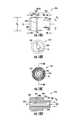
- FIGS. 19A through 19Cdescribe features of the collar 218 .
- At least a portion of the collar 218may be disposed within the strength member gap 215 and may be configured to transfer the clamping force F 3 (see FIG. 29 ) from the fastener 220 to the portion 213 of the strength members 212 in the strength member gap 215 .
- the collar 218may include an inner collar bore 256 formed by an inner collar surface 258 concentric with a longitudinal axis A 2 of the collar 218 .
- the inner collar surface 258may have a diameter D 9 sufficient to let a distal end 260 (see FIG. 17C ) of the fastener 220 pass through the inner collar bore 256 .
- the collar 218may include a first collar surface 262 opposite a second collar surface 264 .
- the first collar surface 262 and the second collar surface 264may contact and transfer the clamping force F 3 between the strength members 212 and the fastener 220 , respectively, when the clamping assembly 214 may be engaged.
- the collar 218may include an outer collar surface 266 which may be concentric to the longitudinal axis A 2 and positioned sufficiently far away from the inner collar surface 258 to provide enough room on the first collar surface 262 and the second collar surface 264 to contact the strength members 212 and the fastener 220 .
- the outer collar surfacemay have a diameter D 10 .
- the diameter D 10may be, for example, less than the diameter D 6 of the bushing contact surface 234 .
- the diameter D 10 greater than the diameter D 6may be unnecessary because the portion of the strength members 212 may be clamped against the clamping surface 244 of the threaded bushing 216 which may be within the diameter D 6 .
- the collar 218may protect the strength members 212 from direct contact with the fastener 220 which may damage the strength members 212 during engagement by rotating.
- the collar 218may or may not rotate during engagement and so may be less damaging to the strength members 212 than the fastener 220 .
- the collar 218may be made of a strong resilient material with a relatively low coefficient of friction, for example, a hard thermoplastic.
- the fastener 220may be standard hex screw including an outer thread 221 compatible with the inner thread 254 ( FIG. 18D ) of the threaded bushing 216 .
- the fastener 220may be long enough to pass through the collar 218 , to provide a strength member gap 215 to accommodate the strength members 212 , and to engage with the inner thread 254 of the threaded bushing 216 .
- the clamping assembly 214may be engaged when the outer thread 221 engages the inner thread 254 of the threaded bushing 216 and applies the clamping force F 3 against the strength members 212 disposed in the strength member gap 215 .
- the fastener 220may be made of a strong resilient material, for example, steel, brass, or thermoplastic.
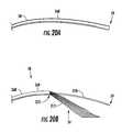
- FIG. 20Adepicts the end 59 of one of the fiber optic cables 58 in unstripped form and a cable jacket 268 forms an exterior longitudinal surface of the fiber optic cable 58 .
- the fiber optic cable 58may comprise at least one optical fiber 270 and the strength members 212 as shown in FIG. 20B when the cable jacket 268 may be removed to a transition point 272 .
- the transition point 272may be disposed between the unstripped portion 269 of the fiber optic cable 58 and the optical fibers 270 which are separated from the strength members 212 .
- the elongated member 26 ( 4 )may include a strain relief portion 68 ( 3 ), sealing portion 86 ( 2 ), and intermediate portion 100 ( 3 ) having a plurality of recesses 70 ( 3 ), plurality of second recesses 90 ( 3 ), and plurality of third recesses 104 ( 3 ), respectively.
- the plurality of recesses 70 ( 3 ), the plurality of second recesses 90 ( 3 ), and the plurality of third recesses 104 ( 3 )may be aligned.
- FIG. 21provides an exemplary process 274 for installing the cable fitting assembly 28 ( 3 ) with the plurality of fiber optic cables 58 into the opening 54 of the fiber optic enclosure 29 .
- the process 274 in FIG. 21will be described using the terminology and information provided above and in reference to FIGS. 8A through 9 , 12 , 20 B, and 22 A through 29 .
- the first step in the process 274may be to attach the elongated cable fitting body 120 to the contact surface 52 of the wall 56 with the locknut 124 as shown in FIGS. 8A and 8B (step 276 in FIG. 21 ).
- the compression cap 128 and the seal ring 138are slid onto the end 59 of the fiber optic cables 58 (step 278 in FIG. 21 ).
- each of the fiber optic cables 58is stripped from the end 59 to the transition point 272 to separate the strength members 212 from the optical fibers 270 (step 280 in FIG. 21 ).
- the threaded bushing 216may be received through the bushing opening 222 and into the bushing bore 224 (step 282 in FIG. 21 ). It is noted that the threaded bushing 216 may be received into the bushing bore 224 in a factory-setting as opposed to the field to minimize the number of parts in the field.
- the clamping surface 244 of the threaded bushing 216may be flush with a first surface 281 of the elongated member 26 ( 4 ) or be disposed outside of the bushing bore 224 . This positioning of the clamping surface 244 may avoid having the clamping force F 3 from the fastener 220 or the collar 218 pushing against the first surface 281 and thereby loosening the threaded bushing 216 from the bushing bore 224 .
- the bushing contact surface 234may communicate with the internal surface 223 to hold the threaded bushing 216 within the bushing bore 224 .
- the internal surface 223may deform to conform to the diamond knurl surface 236 of the threaded bushing 216 to also hold the threaded bushing 216 within the bushing bore 224 .
- the interference surface 239 of the bushing recess 228may communicate with the containment rib 226 of the internal surface 223 of the elongated member 26 ( 4 ) to also hold the threaded bushing 216 within the bushing bore 224 .
- the strength member gap 215may be created by passing the distal end 260 of the fastener 220 through the collar 218 and by partially engaging the outer thread 221 of the fastener 220 with the inner thread 254 of the threaded bushing 216 (step 284 in FIG. 21 ).
- the strength member gap 215may also be created without the collar 218 by directly engaging the outer thread 221 of the fastener 220 with the inner thread 254 .
- the portion 213 of each of the strength members 212 of the fiber optic cable 58may be sequentially received in the strength member gap 215 and wrapped around the protrusion surface 242 of the threaded bushing 216 before a second portion 217 of the strength members 212 may be received through the openings 72 ( 3 ) into the recess 70 ( 3 ) of the strain relief portion 68 ( 3 ) (see FIG. 22B ) of the elongated member 26 ( 4 ) (step 286 in FIG. 21 ).
- the unstripped portion 269 of the fiber optic cable 58may also be received through the openings 72 ( 3 ) and into the recess 70 ( 3 ) so that the unstripped portion 269 may be disposed between the strength member 212 in the recess 70 ( 3 ) and the opening 72 ( 3 ) of the recess 70 ( 3 ) as shown in FIGS. 25A and 26B .
- the transition point 272 of the fiber optic cable 58may be disposed adjacent to a recess exit 293 of the recess 70 ( 3 ).
- the recess exit 293may be configured to release the optical fibers 270 of the plurality of fiber optic cables 58 into the inside 62 of the fiber optic enclosure 29 and to provide the freedom for the strength members 212 to bend from the cable jacket 268 to the clamping assembly 214 .
- each of the strength members 212may include a bend 287 from a direction parallel to the longitudinal axis A 1 to a direction perpendicular (or angled) to the longitudinal axis A 1 of the elongated member 26 ( 4 ) as shown in FIG. 25A .
- the bend 287may help provide strain relief to the fiber optic cables 58 by resisting movement of the strength members 212 .
- the bend 287increases friction resistance to movement of the strength member 212 because tension in the strength members 212 increases a normal force of each of the strength members 212 towards the elongated member 26 ( 4 ) at each of the bends 287 .
- FIG. 25Adepicts the plurality of fiber optic cables 58 may be also received into the plurality of second recesses 90 ( 3 ) in the sealing portion 86 ( 3 ) through the plurality of second openings 92 ( 3 ).
- the plurality of fiber optic cables 58may also be received in the plurality of third recesses 104 ( 3 ) in the intermediate portion 100 ( 3 ) through the plurality of third openings 106 ( 3 ).
- the elongated member 26 ( 4 )may be received within elongated cable fitting body 120 (step 288 in FIG. 21 ). At this point the first end 64 of the elongated member 26 ( 4 ) may be disposed within the inside 62 of the fiber optic enclosure 29 .
- the clamping assembly 214may be engaged to clamp down on the strength members 212 disposed within the strength member gap 215 (step 290 in FIG. 21 ).
- the clamping assembly 214may be engaged with, for example, a wrench 294 .
- the wrench 294may be, for example, a 216 C Tool, made by General Machine Products Company of Trevose, Pa.
- the wrench 294may apply a torque T to the fastener 220 to tighten.
- the torque Tmay be, for example, at least ten (10) inch-pounds and at most twelve (12) inch-pounds.
- the torque Tmay narrow the strength member gap 215 and thereby apply the clamping force F 3 to the portion 213 of the strength members 212 in the strength member gap 215 .
- the clamping force F 3may be in the longitudinal direction A 1 of the elongated member 26 ( 4 ).
- the compression cap 128may be tightened on the second threaded portion 154 of the elongated cable fitting body 120 (step 292 in FIG. 21 ). Tightening the compression cap 128 may seal the opening 54 of the fiber optic enclosure 29 with the sealing portion 86 ( 3 ) of the elongated member 26 ( 4 ).
- fiber optic cablesand/or “optical fibers” include all types of single mode and multi-mode light waveguides, including one or more optical fibers that may be up-coated, colored, buffered, ribbonized and/or have other organizing or protective structure in a cable such as one or more tubes, strength members, jackets or the like.
- the optical fibers disclosed hereincan be single mode or multi-mode optical fibers.
- other types of suitable optical fibersinclude bend-insensitive optical fibers, or any other expedient of a medium for transmitting light signals.
- An example of a bend-insensitive, or bend resistant, optical fiberis ClearCurve® Multimode fiber commercially available from Corning Incorporated. Suitable fibers of this type are disclosed, for example, in U.S. Patent Application Publication Nos. 2008/0166094 and 2009/0169163, the disclosures of which are incorporated herein by reference in their entireties.
Landscapes
- Physics & Mathematics (AREA)
- General Physics & Mathematics (AREA)
- Optics & Photonics (AREA)
- Light Guides In General And Applications Therefor (AREA)
- Mechanical Coupling Of Light Guides (AREA)
- Cable Accessories (AREA)
Abstract
Description
Claims (26)
Priority Applications (6)
| Application Number | Priority Date | Filing Date | Title |
|---|---|---|---|
| US13/456,755US8873926B2 (en) | 2012-04-26 | 2012-04-26 | Fiber optic enclosures employing clamping assemblies for strain relief of cables, and related assemblies and methods |
| AU2013251788AAU2013251788B2 (en) | 2012-04-26 | 2013-04-23 | Fiber optic enclosures employing clamping assemblies for strain relief of cables, and related assemblies and methods |
| CA2871611ACA2871611A1 (en) | 2012-04-26 | 2013-04-23 | Fiber optic enclosures employing clamping assemblies for strain relief of cables, and related assemblies and methods |
| CN201380022287.1ACN104508930B (en) | 2012-04-26 | 2013-04-23 | Fiber Optic Housing and Related Assemblies and Methods Using Clamping Assemblies for Cable Strain Relief |
| EP13781880.3AEP2842209A4 (en) | 2012-04-26 | 2013-04-23 | FIBERGLASS HOUSINGS WITH CLAMP ASSEMBLY FOR THE CABLE RELIEF AND CORRESPONDING ARRANGEMENTS AND METHODS |
| PCT/US2013/037785WO2013163174A1 (en) | 2012-04-26 | 2013-04-23 | Fiber optic enclosures employing clamping assemblies for strain relief of cables, and related assemblies and methods |
Applications Claiming Priority (1)
| Application Number | Priority Date | Filing Date | Title |
|---|---|---|---|
| US13/456,755US8873926B2 (en) | 2012-04-26 | 2012-04-26 | Fiber optic enclosures employing clamping assemblies for strain relief of cables, and related assemblies and methods |
Publications (2)
| Publication Number | Publication Date |
|---|---|
| US20130287360A1 US20130287360A1 (en) | 2013-10-31 |
| US8873926B2true US8873926B2 (en) | 2014-10-28 |
Family
ID=49477359
Family Applications (1)
| Application Number | Title | Priority Date | Filing Date |
|---|---|---|---|
| US13/456,755Expired - Fee RelatedUS8873926B2 (en) | 2012-04-26 | 2012-04-26 | Fiber optic enclosures employing clamping assemblies for strain relief of cables, and related assemblies and methods |
Country Status (6)
| Country | Link |
|---|---|
| US (1) | US8873926B2 (en) |
| EP (1) | EP2842209A4 (en) |
| CN (1) | CN104508930B (en) |
| AU (1) | AU2013251788B2 (en) |
| CA (1) | CA2871611A1 (en) |
| WO (1) | WO2013163174A1 (en) |
Cited By (22)
| Publication number | Priority date | Publication date | Assignee | Title |
|---|---|---|---|---|
| US20120087628A1 (en)* | 2009-03-06 | 2012-04-12 | Adc Telecommunications, Inc. | Fiber optic cable pass-thru fitting |
| US20130028568A1 (en)* | 2011-07-29 | 2013-01-31 | Hubert Blair Beamon | Fiber optic cables seal and/or strain relief members, and related assemblies and methods |
| US20140153876A1 (en)* | 2012-06-13 | 2014-06-05 | Tyco Electronics Netherland Bv | Cable fixture assembly for fastening at least one cable at a cable carrier as well as a splitter comprising such cable fixture assembly |
| US9110267B2 (en) | 2012-10-26 | 2015-08-18 | Ccs Technology, Inc. | Strain relief device for cables and fiber optic distribution device |
| US20160121820A1 (en)* | 2013-07-12 | 2016-05-05 | Yazaki Corporation | Wire Harness |
| US20160209615A1 (en)* | 2015-01-15 | 2016-07-21 | Raycap, S.A. | Fiber optic cable breakout assembly |
| US9488793B2 (en) | 2013-09-10 | 2016-11-08 | Corning Optical Communications LLC | Combined optical fiber and power cable |
| US20170059795A1 (en)* | 2015-09-02 | 2017-03-02 | LGS Innovations LLC | Feedthrough Assembly and Method of Assembling a Feedthrough Assembly |
| US9640986B2 (en) | 2013-10-23 | 2017-05-02 | Raycap Intellectual Property Ltd. | Cable breakout assembly |
| US10181717B2 (en) | 2010-07-13 | 2019-01-15 | Raycap S.A. | Overvoltage protection system for wireless communication systems |
| US10180553B2 (en)* | 2017-02-17 | 2019-01-15 | Corning Research & Development Corporation | Terminal assemblies, end cap assemblies, and fiber optic enclosures incorporating the same |
| US10429604B2 (en) | 2015-11-03 | 2019-10-01 | Raycap S.A. | Modular fiber optic cable splitter |
| US10802237B2 (en) | 2015-11-03 | 2020-10-13 | Raycap S.A. | Fiber optic cable management system |
| US10812664B2 (en) | 2017-01-20 | 2020-10-20 | Raycap S.A. | Power transmission system for wireless communication systems |
| US10845542B1 (en) | 2019-08-19 | 2020-11-24 | Afl Telecommunications Llc | Cable node transition assemblies |
| US10971928B2 (en) | 2018-08-28 | 2021-04-06 | Raycap Ip Assets Ltd | Integrated overvoltage protection and monitoring system |
| US11025040B2 (en)* | 2018-08-21 | 2021-06-01 | Vitaliy Lyvytsky | Modular electrical conduit split assembly |
| US11251608B2 (en) | 2010-07-13 | 2022-02-15 | Raycap S.A. | Overvoltage protection system for wireless communication systems |
| US11359659B2 (en)* | 2016-08-31 | 2022-06-14 | Beijing Surgerii Technology Co., Ltd. | Locking device |
| US11677164B2 (en) | 2019-09-25 | 2023-06-13 | Raycap Ip Assets Ltd | Hybrid antenna distribution unit |
| US20250015573A1 (en)* | 2023-07-05 | 2025-01-09 | Preformed Line Products Company | Cable retainer assemblies and methods of retaining cables |
| US12237134B2 (en) | 2021-12-28 | 2025-02-25 | Raycap Ip Assets Ltd | Circuit protection for hybrid antenna distribution units |
Families Citing this family (12)
| Publication number | Priority date | Publication date | Assignee | Title |
|---|---|---|---|---|
| US9448365B2 (en) | 2014-12-31 | 2016-09-20 | Commscope, Inc. Of North Carolina | Trunk gland adapters and related trunk gland units and methods of connecting trunk cables to fiber optic enclosures |
| US20190314098A1 (en)* | 2016-07-14 | 2019-10-17 | Intuitive Surgical Operations, Inc. | Routing mechanisms for surgical instruments, and related devices, systems, and methods |
| US10928592B2 (en)* | 2017-02-08 | 2021-02-23 | Commscope Technologies Llc | Sectional housing for fiber optic splices |
| CN107255852B (en)* | 2017-08-14 | 2019-05-31 | 江苏法尔胜光电科技有限公司 | A kind of installation method of straining and sensing optical cable |
| CN109283624B (en)* | 2018-11-29 | 2020-05-12 | 武汉光迅科技股份有限公司 | Strip-shaped optical fiber fixing seat and using method thereof |
| WO2021045908A1 (en) | 2019-09-06 | 2021-03-11 | Corning Research & Development Corporation | Cable seal and strain relief assembly |
| EP4025944B1 (en) | 2019-09-06 | 2025-08-06 | Corning Research & Development Corporation | Cable strain relief assembly |
| WO2021262489A1 (en) | 2020-06-22 | 2021-12-30 | Corning Research & Development Corporation | Cable seal and strain relief assembly |
| US12249817B2 (en) | 2021-11-30 | 2025-03-11 | Corning Research & Development Corporation | Telecommunication cable strain relief assemblies |
| DE102023103812A1 (en)* | 2023-02-16 | 2024-08-22 | Wieland Electric Gmbh | Fixing of wires in a connector attachment |
| US20240427104A1 (en)* | 2023-06-22 | 2024-12-26 | Afl Telecommunications Llc | Optical fiber connection fastener |
| US20250020883A1 (en)* | 2023-07-10 | 2025-01-16 | Sterlite Technologies Limited | High-Density Fiber Enclosure |
Citations (507)
| Publication number | Priority date | Publication date | Assignee | Title |
|---|---|---|---|---|
| US2047152A (en) | 1932-10-22 | 1936-07-07 | Galvin Mfg Corp | Automobile radio cable |
| US2853775A (en) | 1955-03-31 | 1958-09-30 | Harcourt C Drake | Method of preventing shelling in railroad rails |
| DE1430906A1 (en) | 1964-05-23 | 1969-09-04 | Daimler Benz Ag | Disc brake |
| US3620875A (en) | 1964-12-11 | 1971-11-16 | Ema Corp | Electromagnetic adhesive and method of joining material thereby |
| GB1324177A (en) | 1970-11-04 | 1973-07-18 | Oberspree Kabelwerke Veb K | |
| US3845552A (en) | 1972-03-02 | 1974-11-05 | Method of making an encapsulated assembly | |
| US3879575A (en) | 1974-02-21 | 1975-04-22 | Bell Telephone Labor Inc | Encapsulating compound and closure |
| US3912855A (en) | 1973-04-20 | 1975-10-14 | John T Thompson | Encapsulating splice assembly |
| US3912854A (en) | 1970-01-26 | 1975-10-14 | John T Thompson | Encapsulated conductor junction |
| US4085286A (en) | 1974-09-27 | 1978-04-18 | Raychem Corporation | Heat-recoverable sealing article with self-contained heating means and method of sealing a splice therewith |
| US4107451A (en) | 1975-11-19 | 1978-08-15 | Trech, Inc. | Reinforced splice joint and method of making same |
| US4152539A (en) | 1977-10-21 | 1979-05-01 | Northern Telecom Limited | Telecommunication cable splices |
| US4213018A (en) | 1978-06-06 | 1980-07-15 | Crouse-Hinds Company | Explosion-proof contact assembly and method of forming the same |
| US4266853A (en) | 1979-03-12 | 1981-05-12 | Northern Telecom Limited | Device for organizing optical fibers and the like |
| US4322573A (en) | 1980-03-11 | 1982-03-30 | Northern Telecom Limited | Encapsulation of telecommunications cable splices |
| GB2087170A (en) | 1980-11-05 | 1982-05-19 | Eilentropp Hew Kabel | Pull-resistant pressure-tight and moistureresistant connections |
| US4343844A (en) | 1980-11-17 | 1982-08-10 | Eaton Corporation | Shrinkable sleeve adapted for cable and tubing gas flow blocking |
| US4360268A (en) | 1980-11-10 | 1982-11-23 | Gte Automatic Electric Labs Inc. | Method and apparatus for measuring the insertion loss of a splice in an optical fiber |
| JPS58105114A (en) | 1981-12-17 | 1983-06-22 | Hitachi Cable Ltd | Optical fiber cable line with branch |
| US4405083A (en) | 1982-03-19 | 1983-09-20 | Northern Telecom Limited | Moulding apparatus for encapsulating cable splices |
| US4413881A (en) | 1979-07-26 | 1983-11-08 | Northern Telecom Limited | Optical fiber hermetic seal |
| EP0110673A1 (en) | 1982-11-26 | 1984-06-13 | Minnesota Mining And Manufacturing Company | Electrical cable connections for gas-pressurized telecommunication cables |
| US4467137A (en) | 1982-06-21 | 1984-08-21 | Raychem Limited | Cable breakout article |
| US4475935A (en) | 1981-07-24 | 1984-10-09 | Nippon Telegraph & Telephone Public Corporation | Joining method to obtain elongated coated optical fiber |
| US4481380A (en) | 1982-08-26 | 1984-11-06 | Alden Research Foundation | High voltage insulator for electrical components having telescoping insulative sleeves |
| EP0124987A2 (en) | 1983-04-07 | 1984-11-14 | Lockheed Corporation | Underwater connector |
| US4490315A (en) | 1982-02-04 | 1984-12-25 | Northern Telecom Limited | Methods of moulding of plastics articles |
| US4512628A (en) | 1983-05-31 | 1985-04-23 | Gte Products Corporation | Splice casing assembly |
| US4528150A (en) | 1982-09-23 | 1985-07-09 | Northern Telecom Limited | Methods and apparatus for sealing articles |
| US4528419A (en) | 1983-12-12 | 1985-07-09 | Northern Telecom Limited | Forming of cable splice closures |
| JPS60169813A (en) | 1984-02-15 | 1985-09-03 | Sumitomo Electric Ind Ltd | Optical branching terminal |
| JPS60169815A (en) | 1984-02-13 | 1985-09-03 | Dainichi Nippon Cables Ltd | Connection end part of cable with optical fiber |
| US4549039A (en) | 1983-06-08 | 1985-10-22 | Northern Telecom Limited | Telecommunications cable splice closures |
| US4550220A (en) | 1983-11-04 | 1985-10-29 | National Industries, Inc. | Splice insulator assembly |
| US4553812A (en) | 1982-06-08 | 1985-11-19 | Mitsubishi Denki Kabushiki Kaisha | Penetration assembly for bringing an optical fiber cable through a vessel wall |
| US4556281A (en) | 1983-12-19 | 1985-12-03 | Gte Products Corporation | End plug for a fiber optic in-line splice case assembly |
| US4570032A (en) | 1984-09-07 | 1986-02-11 | Northern Telecom Limited | Sealing closure for a cable splice |
| US4581480A (en) | 1984-09-07 | 1986-04-08 | Northern Telecom Limited | Cable splice closure and strain relief |
| US4589939A (en) | 1984-02-17 | 1986-05-20 | Raychem Corporation | Insulating multiple-conductor cables using coated insert means |
| US4591330A (en) | 1984-11-05 | 1986-05-27 | Northern Telecom Limited | Moulding equipment |
| US4592721A (en) | 1982-09-23 | 1986-06-03 | Northern Telecom Limited | Apparatus for sealably encapsulating articles |
| US4595256A (en) | 1982-04-08 | 1986-06-17 | Les Cables De Lyon | Connection between the ends of two undersea optical fiber cables and method of manufacturing said connection |
| US4602840A (en) | 1984-06-01 | 1986-07-29 | Harvey Hubbell Incorporated | Under-carpet connection system |
| US4609773A (en) | 1985-07-08 | 1986-09-02 | Northern Telecom Limited | Seal assembly |
| US4610738A (en) | 1985-01-04 | 1986-09-09 | Raychem Corporation | Encapsulating a splice with a gel-filled case |
| JPS61220536A (en) | 1985-03-27 | 1986-09-30 | Hitachi Ltd | Information transmission line for car |
| US4625073A (en) | 1985-03-11 | 1986-11-25 | Raychem Corporation | Cable having a branch-off region sealed with a branch-off article and method of making same |
| US4629597A (en) | 1985-07-08 | 1986-12-16 | Northern Telecom Limited | Forming of cable splice closures |
| US4648606A (en) | 1985-07-08 | 1987-03-10 | Northern Telecom Limited | Seals |
| US4648919A (en) | 1984-09-18 | 1987-03-10 | Raychem Corp. | Protection of cable splice |
| US4652072A (en) | 1986-04-28 | 1987-03-24 | Wire Tech Incorporated | Cable-connector assembly |
| US4654474A (en) | 1985-06-19 | 1987-03-31 | Northern Telecom Limited | Forming of cable splice closures |
| DE3537684A1 (en) | 1985-10-23 | 1987-04-23 | Rheydt Kabelwerk Ag | Optical fibre cable branch and method for producing it |
| US4665279A (en) | 1986-03-31 | 1987-05-12 | Mpx Systems, Inc. | Protective container for transmission cable splice |
| US4666537A (en) | 1980-04-24 | 1987-05-19 | Thomas & Betts Corporation | Method of sealing and repairing electrical cables |
| US4670069A (en) | 1984-09-18 | 1987-06-02 | Raychem Corp. | Protection of cable splice |
| US4669802A (en) | 1986-03-26 | 1987-06-02 | Amp Incorporated | Outlet for optical fiber connectors |
| US4670980A (en) | 1985-06-28 | 1987-06-09 | Northern Telecom Limited | Manufacture of sealing closures for a telecommunications cable splice |
| US4673242A (en) | 1981-12-21 | 1987-06-16 | Thomas & Betts Corporation | Movable closure for optical elements |
| US4678866A (en) | 1985-07-08 | 1987-07-07 | Northern Telecom Limited | Forming of cable splice closures |
| US4684764A (en) | 1985-12-09 | 1987-08-04 | Amerace Corporation | High voltage cable splice protector |
| US4685799A (en) | 1986-01-13 | 1987-08-11 | The United States Of America As Represented By The Secretary Of The Navy | Integrated optical time domain reflectometer/insertion loss measurement system |
| US4701010A (en) | 1984-08-30 | 1987-10-20 | Adc Fiber Optics Corporation | Unitary body optical coupler |
| US4701574A (en) | 1985-02-06 | 1987-10-20 | Raychem Corp. | Cable sealing apparatus |
| US4702551A (en) | 1984-10-11 | 1987-10-27 | Reliance Comm/Tec Corporation | Method and apparatus for handling and storing cabled spliced ends of fiber optics |
| US4704499A (en) | 1986-06-18 | 1987-11-03 | American Telephone And Telegraph Company At&T Bell Laboratories | Locking mechanism for aerial cable closure and terminals |
| US4708476A (en) | 1986-04-23 | 1987-11-24 | Northern Telecom Limited | Method of determining optical fiber splice loss |
| US4717231A (en) | 1983-01-05 | 1988-01-05 | Vincent Dewez | Interconnecting and distributing box for optical fibers |
| EP0251396A1 (en) | 1986-06-20 | 1988-01-07 | E.I. Du Pont De Nemours And Company | Branch connector for coaxial cable |
| US4721830A (en) | 1987-06-25 | 1988-01-26 | Communications Technolgy Corporation | Cable enclosure |
| US4725035A (en) | 1985-06-28 | 1988-02-16 | Northern Telecom Limited | Apparatus for manufacture of sealing closures for a telecommunications cable splice |
| US4732628A (en) | 1980-04-24 | 1988-03-22 | Thomas & Betts Corporation | Method of sealing and repairing electrical cables |
| US4736071A (en) | 1986-03-17 | 1988-04-05 | American Telephone And Telegraph Company, At&T Bell Laboratories | Encapsulation system with pressurization means |
| US4742541A (en) | 1983-10-25 | 1988-05-03 | Northern Telecom Limited | Telecommunications interface with protector modules |
| US4747020A (en) | 1986-05-16 | 1988-05-24 | Adc Telecommunications, Inc. | Wire distribution apparatus |
| US4761052A (en) | 1986-01-31 | 1988-08-02 | N. V. Raychem S.A. | Optical fibre splice case |
| US4764232A (en) | 1986-09-26 | 1988-08-16 | Raychem Corporation | Method of protecting a cable splice with a splice closure having pressure measuring means |
| JPS63130317U (en) | 1987-02-19 | 1988-08-25 | ||
| JPS63136007U (en) | 1987-02-25 | 1988-09-07 | ||
| JPS63257701A (en) | 1987-04-15 | 1988-10-25 | Matsushita Electric Works Ltd | Optical fiber wiring equipment |
| US4785376A (en) | 1987-04-14 | 1988-11-15 | Dively Robert C | Utility pedestal construction |
| JPS63180915U (en) | 1987-05-15 | 1988-11-22 | ||
| JPS63287916A (en) | 1987-05-21 | 1988-11-25 | Furukawa Electric Co Ltd:The | Terminal of composite cable |
| US4792203A (en) | 1985-09-17 | 1988-12-20 | Adc Telecommunications, Inc. | Optical fiber distribution apparatus |
| JPS63200105U (en) | 1987-06-08 | 1988-12-23 | ||
| US4805979A (en) | 1987-09-04 | 1989-02-21 | Minnesota Mining And Manufacturing Company | Fiber optic cable splice closure |
| US4818824A (en) | 1987-08-19 | 1989-04-04 | American Telephone And Telegraph Company, At&T Bell Laboratories | Closure for aerial telephone cable splices |
| US4822434A (en) | 1986-07-10 | 1989-04-18 | Yazaki Corporation | Method for forming cover layer over wire joint |
| US4834479A (en) | 1986-12-11 | 1989-05-30 | American Telephone And Telegraph Company | High and low pressure fluidblock assembly |
| EP0320189A2 (en) | 1987-12-11 | 1989-06-14 | Minnesota Mining And Manufacturing Company | Cable closure |
| EP0320236A2 (en) | 1987-12-11 | 1989-06-14 | Minnesota Mining And Manufacturing Company | Cable closure end cap |
| US4850014A (en) | 1987-03-10 | 1989-07-18 | Communications Systems, Inc. | Multiple dwelling interface box |
| US4859809A (en) | 1988-04-27 | 1989-08-22 | Raychem Corporation | Splice case |
| US4867524A (en) | 1988-09-08 | 1989-09-19 | United Technologies Corporation | Metallic bond for mounting of optical fibers to integrated optical chips |
| US4875952A (en) | 1984-06-11 | 1989-10-24 | American Telephone And Telegraph Company, At&T Bell Laboratories | Forced encapsulation means for a cable |
| US4882647A (en) | 1988-12-15 | 1989-11-21 | Keptel, Inc. | Combination apparatus for clamping ground conductor and for mounting lightning protector |
| US4884863A (en) | 1989-03-06 | 1989-12-05 | Siecor Corporation | Optical fiber splicing enclosure for installation in pedestals |
| US4913512A (en) | 1983-12-19 | 1990-04-03 | Gte Products Corporation | Fiber optic in-line splice case assembly |
| US4917615A (en) | 1988-11-18 | 1990-04-17 | Franks George J Jr | Ground bracket |
| US4927227A (en) | 1988-10-31 | 1990-05-22 | At&T Bell Laboratories | Optical fiber cable closure |
| US4932742A (en) | 1989-01-27 | 1990-06-12 | Alcatel Na, Inc. | Fiber optic wavelength division multiplexing module |
| US4952798A (en) | 1990-01-03 | 1990-08-28 | Amp Incorporated | Optical simulator with loop-back attenuator and optical thin film |
| US4958900A (en) | 1989-03-27 | 1990-09-25 | General Electric Company | Multi-fiber holder for output coupler and methods using same |
| US4960317A (en) | 1988-08-23 | 1990-10-02 | Amp Incorporated | Wall outlet for a fiber optic connector assembly |
| US4961623A (en) | 1989-09-05 | 1990-10-09 | Siecor Corporation | Preterminated optical cable |
| DE3900021A1 (en) | 1989-01-02 | 1990-10-11 | Anton Dipl Ing Hartmann | Fiber optic connector |
| US4963698A (en) | 1985-05-02 | 1990-10-16 | Raychem Corporation | Cable sealing |
| US4976510A (en) | 1989-11-20 | 1990-12-11 | Siecor Corporation | Communication outlet |
| US4982083A (en) | 1990-01-03 | 1991-01-01 | Amp Incorporated | Optical simulator with loop-back attenuator and filter |
| US4986762A (en) | 1989-08-15 | 1991-01-22 | Minnesota Mining And Manufacturing Company | Termination module for use in an array of modules |
| US4989939A (en) | 1984-06-21 | 1991-02-05 | Imperial Chemical Industries Plc | Coupler for optical fibers |
| USD314759S (en) | 1988-11-28 | 1991-02-19 | Keptel, Inc. | On-premise enclosure for cable television components or the like |
| US4995688A (en) | 1989-07-31 | 1991-02-26 | Adc Telecommunications, Inc. | Optical fiber distribution frame |
| US5004315A (en) | 1983-10-20 | 1991-04-02 | Furukawa Electric Co., Ltd. | Optical cable and optical cable line |
| WO1991005281A1 (en) | 1989-09-29 | 1991-04-18 | Northern Telecom Limited | Connector holders and distribution frame and connector holder assemblies for optical cable |
| US5011256A (en) | 1988-10-28 | 1991-04-30 | E. I. Du Pont De Nemours And Company | Package for an opto-electronic component |
| US5029958A (en) | 1989-04-28 | 1991-07-09 | Scientific-Atlanta, Inc. | Optical fiber enclosure for optoelectronic converter |
| US5031984A (en) | 1990-01-17 | 1991-07-16 | Alcatel Na | Optical fiber electro-optical module |
| WO1991010927A1 (en) | 1990-01-22 | 1991-07-25 | Porta Systems Corp. | Optical fiber cable distribution frame and support |
| USD318653S (en) | 1989-05-15 | 1991-07-30 | Keptel, Inc. | Subscriber network interface enclosure |
| US5042901A (en) | 1990-07-31 | 1991-08-27 | Siecor Corporation | Preconnectorized optical splice closure |
| US5046811A (en) | 1989-07-17 | 1991-09-10 | Jung Roger E | Junction box for optical communications cords, and gland assembly for cord |
| US5050949A (en) | 1990-06-22 | 1991-09-24 | At&T Bell Laboratories | Multi-stage optical fiber amplifier |
| US5052775A (en) | 1989-08-15 | 1991-10-01 | Minnesota Mining And Manufacturing Company | Optical fiber module termination array and panel |
| US5052773A (en) | 1990-06-14 | 1991-10-01 | Northern Telecom Limited | Assemblies of tube and fiber units and a unit position control member |
| US5054868A (en) | 1990-08-29 | 1991-10-08 | The United States Of America As Represented By The Secretary Of The Navy | Armored optical fiber cable interconnection for dual payout systems |
| US5066095A (en) | 1990-02-09 | 1991-11-19 | Alcatel Cable | Jointing box for optical fiber cables |
| US5068890A (en) | 1986-10-22 | 1991-11-26 | Nilssen Ole K | Combined signal and electrical power distribution system |
| US5074808A (en) | 1991-02-06 | 1991-12-24 | Amp Incorporated | Molded strain relief in back shell |
| US5077815A (en) | 1988-09-30 | 1991-12-31 | Fujitsu Limited | Apparatus for optically connecting a single-mode optical fiber to a multi-mode optical fiber |
| US5076688A (en) | 1990-03-23 | 1991-12-31 | Amp Incorporated | Optical simulator with loop-back attenuator having metalized optical fiber |
| US5091987A (en) | 1991-02-11 | 1992-02-25 | G & H Technology, Inc. | Fiber optic hermetic connector |
| US5093885A (en) | 1990-07-11 | 1992-03-03 | Adc Telecommunications, Inc. | Fiber optic connector module |
| US5097529A (en) | 1991-03-22 | 1992-03-17 | At&T Bell Laboratories | Space-saving optical fiber cable closure |
| US5099088A (en) | 1989-07-19 | 1992-03-24 | Three Bond Co., Ltd. | Means for splicing wires |
| GB2248729A (en) | 1990-08-14 | 1992-04-15 | Michael John Bryant | Flexible reinforced tubes for cable bend strain relief |
| FR2667955A1 (en) | 1990-10-10 | 1992-04-17 | Dietz Kabeltechnik | FEMALE BASE FOR FIBER OPTIC MALE SOCKET. |
| US5109458A (en) | 1990-10-30 | 1992-04-28 | At&T Bell Laboratories | Cable seal |
| US5115105A (en) | 1990-02-21 | 1992-05-19 | Amphenol Corporation | Overbraided in-line data bus loom |
| US5121458A (en) | 1991-04-05 | 1992-06-09 | Alcatel Na Cable Systems, Inc. | Preterminated fiber optic cable |
| US5122069A (en) | 1989-07-28 | 1992-06-16 | Amp Incorporated | Access flooring module |
| US5125060A (en) | 1991-04-05 | 1992-06-23 | Alcatel Na Cable Systems, Inc. | Fiber optic cable having spliceless fiber branch and method of making |
| US5127082A (en) | 1991-03-22 | 1992-06-30 | The Siemon Company | Fiber optic patch panel |
| US5129030A (en) | 1991-05-30 | 1992-07-07 | At&T Bell Laboratories | Movable lightguide connector panel |
| US5133039A (en) | 1990-10-29 | 1992-07-21 | At&T Bell Laboratories | Aerial fiber optic cable case |
| US5133038A (en) | 1980-04-17 | 1992-07-21 | Reliance Comm/Tec. Corporation | Fiber optic splice case |
| US5142606A (en) | 1990-01-22 | 1992-08-25 | Porta Systems Corp. | Optical fiber cable distribution frame and support |
| US5155303A (en) | 1991-05-17 | 1992-10-13 | At&T Bell Laboratories | Cable closure including grommet having enhanced sealing capability |
| EP0511147A1 (en) | 1991-04-22 | 1992-10-28 | Telefonica De Espana, S.A. | Universal access optical fiber junction box |
| EP0512811A1 (en) | 1991-05-06 | 1992-11-11 | COMPUTER CRAFTS, Inc. | Branching method for a multi-fiber fiberoptic cable |
| US5179618A (en) | 1990-07-11 | 1993-01-12 | Adc Telecommunications, Inc. | Fiber optic connector module |
| US5185844A (en) | 1991-07-29 | 1993-02-09 | At&T Bell Laboratories | Closure for optical fiber connective arrangements and method of providing same |
| US5185845A (en) | 1990-12-13 | 1993-02-09 | At&T Bell Laboratories | Optical fiber closure having enhanced storage capability |
| US5194692A (en) | 1990-09-27 | 1993-03-16 | Amphenol Corporation | Uncased data bus coupler |
| US5204929A (en) | 1991-09-04 | 1993-04-20 | Reliance Comm/Tec Corporation | Fiber patch panel |
| US5210812A (en) | 1991-04-05 | 1993-05-11 | Alcatel Na Cable Systems, Inc. | Optical fiber cable having spliced fiber branch and method of making the same |
| US5209958A (en) | 1992-06-02 | 1993-05-11 | E. I. Du Pont De Nemours And Company | Multilayer laminates from blow moldable thermoplastic polyamide and polyvinyl alcohol resins |
| US5212761A (en) | 1992-04-27 | 1993-05-18 | At&T Bell Laboratories | Fiber optic module |
| US5214735A (en) | 1992-04-06 | 1993-05-25 | Adc Telecommunications, Inc. | Fiber optic connector retainer |
| US5217808A (en) | 1989-11-29 | 1993-06-08 | At&T Bell Laboratories | Water blocked cable portion and methods of making same |
| US5224187A (en) | 1992-04-29 | 1993-06-29 | Scientific-Atlanta, Inc. | Fiber optic cable connectors providing strain relief |
| USD337313S (en) | 1991-09-19 | 1993-07-13 | Scientific-Atlanta, Inc. | Dual bay electrical enclosure |
| US5231687A (en) | 1990-06-04 | 1993-07-27 | Bicc Plc | Termination system for optical fibres |
| US5235665A (en) | 1991-05-06 | 1993-08-10 | Sirti S.P.A. | Branching device for fibre-optic cables |
| US5241611A (en) | 1989-10-04 | 1993-08-31 | British Telecommunications Public Limited Company | Cable joint |
| US5245151A (en) | 1989-04-07 | 1993-09-14 | Minnesota Mining And Manufacturing Company | Method and article for microwave bonding of splice closure |
| US5247135A (en) | 1992-02-07 | 1993-09-21 | Minnesota Mining And Manufacturing Company | Aerial terminal |
| US5259047A (en) | 1993-04-01 | 1993-11-02 | Northern Telecom Limited | Methods for determining optical fiber joint loss and joint elements useful in those methods |
| US5260957A (en) | 1992-10-29 | 1993-11-09 | The Charles Stark Draper Laboratory, Inc. | Quantum dot Laser |
| US5267122A (en) | 1992-06-15 | 1993-11-30 | Alcatel Network Systems, Inc. | Optical network unit |
| WO1993026069A1 (en) | 1992-06-15 | 1993-12-23 | N.V. Raychem S.A. | Cable sealing and/or feedthrough device |
| US5308954A (en) | 1991-10-02 | 1994-05-03 | At&T Bell Laboratories | Heat sealing apparatus for splice case having two half shells |
| US5322973A (en) | 1992-03-06 | 1994-06-21 | Communication Technology Corporation | Aerial closure |
| US5347089A (en) | 1990-06-22 | 1994-09-13 | Raychem Limited | Branch off |
| US5353367A (en) | 1993-11-29 | 1994-10-04 | Northern Telecom Limited | Distribution frame and optical connector holder combination |
| US5357565A (en) | 1992-12-16 | 1994-10-18 | Siecor Puerto Rico, Inc. | Hinge shield for network interface enclosure |
| EP0620462A1 (en) | 1993-04-16 | 1994-10-19 | The Whitaker Corporation | Splice tray rack and cabinet for fiber optic cables |
| US5363465A (en) | 1993-02-19 | 1994-11-08 | Adc Telecommunications, Inc. | Fiber optic connector module |
| US5363467A (en) | 1993-05-28 | 1994-11-08 | Minnesota Mining And Manufacturing Company | Compact fiber optic housing |
| US5367598A (en) | 1993-10-21 | 1994-11-22 | Nec America, Inc. | Interface chassis for fiber optic transport system |
| US5376196A (en) | 1991-07-11 | 1994-12-27 | Kabelmetal Electro Gmbh | Method for sealing the end of a heat-shrunk sleeve |
| US5378853A (en) | 1992-01-29 | 1995-01-03 | Filotex | Shielded multibranch harness |
| US5381501A (en) | 1994-01-27 | 1995-01-10 | General Motors Corporation | Fiber optic bundle connector including a hollow cone and a terminal block |
| US5386490A (en) | 1993-07-01 | 1995-01-31 | E-Tek Dynamics, Inc. | Automated workstation for the manufacture of optical fiber couplers |
| US5394502A (en) | 1993-12-21 | 1995-02-28 | United Technologies Corporation | Fiber optic cable harness break-out fitting |
| WO1995007478A1 (en) | 1993-09-10 | 1995-03-16 | British Telecommunications Public Limited Company | Break-out tray |
| US5402515A (en) | 1994-03-01 | 1995-03-28 | Minnesota Mining And Manufacturing Company | Fiber distribution frame system, cabinets, trays and fiber optic connector couplings |
| US5410105A (en) | 1992-09-21 | 1995-04-25 | Nitto Denko Corporation | Method for waterproofing junction of main and branch wires and cover therefor |
| US5418874A (en) | 1994-01-19 | 1995-05-23 | At&T Corp. | Force transfer system for an optical fiber connector |
| US5420958A (en) | 1990-05-21 | 1995-05-30 | Minnesota Mining And Manufacturing Company | Optical fiber distribution center |
| US5425121A (en) | 1994-02-02 | 1995-06-13 | Siecor Corporation | Cable assembly for use with opto-electronic equipment enclosures |
| US5432875A (en) | 1993-02-19 | 1995-07-11 | Adc Telecommunications, Inc. | Fiber optic monitor module |
| USRE34995E (en) | 1991-12-17 | 1995-07-18 | Grass Ag | Adjustable recessed door hinge |
| US5440665A (en) | 1993-04-16 | 1995-08-08 | Raychem Corporation | Fiber optic cable system including main and drop cables and associated fabrication method |
| US5440655A (en) | 1993-12-29 | 1995-08-08 | At&T Corp. | Optical fiber connector bypass device and method using same |
| US5442726A (en) | 1994-02-22 | 1995-08-15 | Hubbell Incorporated | Optical fiber storage system |
| US5446823A (en) | 1994-01-26 | 1995-08-29 | Raychem Corporation | Aerial, pedestal, below grade, or buried optical fiber closure |
| US5446822A (en) | 1993-05-28 | 1995-08-29 | Minnesota Mining And Manufacturing Company | Connector clip for fiber optic housing |
| WO1995023449A1 (en) | 1994-02-28 | 1995-08-31 | Raychem Corporation | Rodent-proof aerial splice closure |
| US5450517A (en) | 1994-07-01 | 1995-09-12 | The Whitaker Corporation | Re-enterable fiber optic splicer for data communications |
| US5450518A (en) | 1994-10-13 | 1995-09-12 | At&T Corp. | Optical fiber cable splice closure |
| US5475781A (en) | 1994-09-15 | 1995-12-12 | Chang; Peter C. | Optical fiber connector assembly with loop-back structure |
| US5481639A (en) | 1994-10-28 | 1996-01-02 | At&T Corp. | Compact closure for optical fiber cable |
| US5491766A (en) | 1993-04-16 | 1996-02-13 | Raychem Corporation | Bonding assembly for fiber optic cable and associated method |
| US5495549A (en) | 1994-02-18 | 1996-02-27 | Keptel, Inc. | Optical fiber splice closure |
| US5509099A (en) | 1995-04-26 | 1996-04-16 | Antec Corp. | Optical fiber closure with sealed cable entry ports |
| US5509202A (en) | 1992-11-19 | 1996-04-23 | The United States Of America As Represented By The Secretary Of The Navy | Hydrostatic sealing sleeve method for utilizing wire connections |
| US5517592A (en) | 1993-10-22 | 1996-05-14 | Kabelmetal Electro Gmbh | Sleeve for branch or joint areas in optical or electrical cables |
| US5553186A (en) | 1995-03-31 | 1996-09-03 | Minnesota Mining And Manufacturing Company | Fiber optic dome closure |
| USD377339S (en) | 1995-06-30 | 1997-01-14 | Motorola, Inc. | Electronics enclosure |
| US5598499A (en) | 1995-11-01 | 1997-01-28 | Lucent Technologies, Inc. | Seal for cable splice closure |
| US5623542A (en) | 1993-02-16 | 1997-04-22 | Antec Corp. | Combination telephone network interface and cable television apparatus and cable television module |
| US5633973A (en) | 1994-12-08 | 1997-05-27 | Alcatel Cable Interface | Splice box for splicing together opticl-fiber cables |
| US5638481A (en) | 1995-09-26 | 1997-06-10 | Lucent Technologies Inc. | Flush mounted outlet |
| US5640482A (en) | 1995-08-31 | 1997-06-17 | The Whitaker Corporation | Fiber optic cable management rack |
| US5644671A (en) | 1995-06-23 | 1997-07-01 | Preformed Line Products Company | Optical fiber spice case with cross connect feature |
| US5645449A (en) | 1995-02-21 | 1997-07-08 | The Whitaker Corporation | Low profile mixed media information outlet |
| US5659650A (en) | 1995-09-26 | 1997-08-19 | Lucent Technologies Inc. | Hinged faceplate |
| US5666453A (en) | 1994-07-15 | 1997-09-09 | Roy Witte | Fiber optic jumper cables and tracing method using same |
| US5684911A (en) | 1995-09-01 | 1997-11-04 | Lucent Technologies Inc. | Sub-surface fiber optic splice housing and method of splicing fiber optic cable |
| EP0805536A1 (en) | 1996-05-01 | 1997-11-05 | Bowthorpe Plc | Cable enclosure |
| US5689607A (en) | 1994-12-08 | 1997-11-18 | Alcatel Cable Interface | Device for holding at least one optical fiber cable, and a splice box making use of the device |
| US5696864A (en) | 1996-09-18 | 1997-12-09 | Communications Technology Corporation | Aerial enclosure for coupling data signals to a customer site |
| US5701380A (en) | 1996-06-24 | 1997-12-23 | Telect, Inc. | Fiber optic module for high density supply of patching and splicing |
| US5708753A (en) | 1996-09-24 | 1998-01-13 | Lucent Technologies Inc. | Method of recovering from a fiber-cable cut using random splicing reconnection |
| US5708742A (en) | 1996-06-18 | 1998-01-13 | Northern Telecom Limited | Combinations of printed circuit boards and face plates |
| US5732180A (en) | 1995-06-09 | 1998-03-24 | Multilink, Inc. | Method and apparatus for sealing fiber optic entryways to a sealed enclosure |
| US5734776A (en) | 1996-08-28 | 1998-03-31 | Adc Telecommunications, Inc. | Outside plant cross-connect apparatus |
| US5741158A (en) | 1996-07-29 | 1998-04-21 | The Whitaker Corporation | Communications outlet having termination aid platform |
| US5745633A (en) | 1996-12-24 | 1998-04-28 | Siecor Corporation | Fiber optic cable assembly for securing a fiber optic cable within an input port of a splice closure |
| US5754724A (en) | 1996-11-08 | 1998-05-19 | Antec Corporation | Fiber optic support apparatus |
| JPH10133033A (en) | 1996-10-29 | 1998-05-22 | Fujikura Ltd | Optical connector storage parts |
| US5758003A (en) | 1996-03-15 | 1998-05-26 | Adc Telecommunications, Inc. | High density fiber management |
| US5757997A (en) | 1995-12-22 | 1998-05-26 | Minnesota Mining And Manufacturing Company | Optical fiber connector using fiber spring force alignment groove |
| EP0844504A2 (en) | 1996-11-21 | 1998-05-27 | RXS Kabelgarnituren Gesellschaft mit beschränkter Haftung | Connection box for optical cables |
| US5767448A (en) | 1996-09-30 | 1998-06-16 | Raychem Corporation | Sealing device |
| EP0851257A1 (en) | 1996-12-31 | 1998-07-01 | Siecor Corporation | Optical fiber connector housing |
| US5778122A (en) | 1996-12-24 | 1998-07-07 | Siecor Corporation | Fiber optic cable assembly for interconnecting optical fibers within a receptacle mounted within the wall of an enclosure |
| US5781678A (en) | 1995-01-25 | 1998-07-14 | Sumitomo Electric Industries, Ltd. | Optical fiber path joint member and method of blowing optical fiber |
| USD399190S (en) | 1997-01-02 | 1998-10-06 | Scientific-Atlanta, Inc. | Customer interface unit enclosure |
| US5823646A (en) | 1997-09-02 | 1998-10-20 | Siecor Corporation | Door assembly for optical hardware cabinet |
| US5828807A (en) | 1996-04-30 | 1998-10-27 | Next Level Communications | Optical network unit (ONU) mechanical enclosure |
| USD401568S (en) | 1996-09-13 | 1998-11-24 | Lucent Technologies Inc. | Cover for an electronic and/or optical equipment enclosure |
| US5861575A (en) | 1996-03-19 | 1999-01-19 | Broussard; Blaine L. | Device and method for a fluid stop splice for a submersible cable |
| US5867621A (en) | 1997-04-23 | 1999-02-02 | Siecor Corporation | Adapter and guide pin assembly for coupling of fiber optic connectors |
| US5881200A (en) | 1994-09-29 | 1999-03-09 | British Telecommunications Public Limited Company | Optical fibre with quantum dots |
| EP0903604A2 (en) | 1997-09-22 | 1999-03-24 | Lucent Technologies Inc. | An improved optical switching apparatus for use in the construction mode testing of fibers in an optical cable |
| US5892870A (en) | 1995-11-16 | 1999-04-06 | Fiber Connections Inc. | Fibre optic cable connector |
| US5894540A (en) | 1997-05-22 | 1999-04-13 | Lucent Technologies Inc. | Optical Fiber take-up assembly |
| US5896486A (en) | 1997-05-01 | 1999-04-20 | Lucent Technologies Inc. | Mass splice tray for optical fibers |
| US5898813A (en) | 1994-08-04 | 1999-04-27 | Siemens Aktiengesellschaft | Optical short-circuit plug |
| US5903698A (en) | 1997-04-11 | 1999-05-11 | Wiltron Company | Fiber optic connection assembly |
| US5907653A (en) | 1997-05-01 | 1999-05-25 | Lucent Technologies Inc. | Racetrack grommet for optical fiber cable splice closure |
| US5914846A (en) | 1997-05-06 | 1999-06-22 | Tii Industries, Inc. | Cable interconnection apparatus for network interface device |
| US5917648A (en) | 1994-06-22 | 1999-06-29 | Hewlett-Packard Company | Packaged optical amplifier assembly |
| US5937121A (en) | 1997-01-03 | 1999-08-10 | The Siemon Company | Adapters for coupling optical fiber |
| US5946440A (en) | 1997-11-17 | 1999-08-31 | Adc Telecommunications, Inc. | Optical fiber cable management device |
| US5945633A (en) | 1996-05-23 | 1999-08-31 | The Siemon Company | Rack mountable cable distribution enclosure having an angled adapter plate bracket |
| US5956449A (en) | 1997-02-26 | 1999-09-21 | Nec Corporation | Structure for mounting an optical circuit |
| US5957415A (en) | 1996-12-12 | 1999-09-28 | Hutchinson | Device for fixing at least one fluid pipe to a support |
| USD415118S (en) | 1998-12-04 | 1999-10-12 | Siecor Operations, Llc | Cable enclosure |
| US5969294A (en) | 1997-12-31 | 1999-10-19 | Siecor Operations, Llc | Fiber optic connector cabinet with rotatably mounted adapter panels |
| US5975769A (en) | 1997-07-08 | 1999-11-02 | Telect, Inc. | Universal fiber optic module system |
| US5987203A (en) | 1997-10-09 | 1999-11-16 | Lucent Technologies Inc. | Distribution module for optical couplings |
| US5997186A (en) | 1998-05-13 | 1999-12-07 | Huynh; Van L. | Hybrid cable splice closure and related methods |
| FR2780209A1 (en) | 1998-06-23 | 1999-12-24 | Pirelli Cables Sa | METHOD FOR CONNECTING CABLES, AND DEVICE FOR IMPLEMENTING SAME |
| USRE36592E (en) | 1994-07-01 | 2000-02-29 | Siecor Corporation | Optical receiver stub fitting |
| US6037544A (en) | 1997-11-22 | 2000-03-14 | Lg Chemical Ltd | Splice closure for telecommunications cables |
| US6049413A (en) | 1998-05-22 | 2000-04-11 | Ciena Corporation | Optical amplifier having first and second stages and an attenuator controlled based on the gains of the first and second stages |
| USD422564S (en) | 1997-09-02 | 2000-04-11 | Siecor Corporation | Access door for fiber optic wall mount box |
| US6053054A (en) | 1997-09-26 | 2000-04-25 | Fti Flow Technology, Inc. | Gas flow rate measurement apparatus and method |
| USD424598S (en) | 1997-09-30 | 2000-05-09 | Luxottica Leasing S.P.A. | Eyewear |
| US6061492A (en) | 1997-04-09 | 2000-05-09 | Siecor Corporation | Apparatus and method for interconnecting fiber cables |
| US6061870A (en) | 1998-01-07 | 2000-05-16 | The Burton Corporation | Bushing system |
| US6064791A (en) | 1998-04-24 | 2000-05-16 | New York Telephone | Restoration of loose tube fiber optic cable |
| US6086263A (en) | 1996-06-13 | 2000-07-11 | 3M Innovative Properties Company | Active device receptacle |
| US6104846A (en) | 1998-07-31 | 2000-08-15 | Litton Systems, Inc. | System for splicing sensors into a multiple fiber optical cable |
| JP2000241631A (en) | 1999-02-19 | 2000-09-08 | Fujikura Ltd | Optical module and optical distribution frame |
| US6122420A (en) | 1997-03-31 | 2000-09-19 | Ando Electric Co., Ltd. | Optical loopback apparatus |
| USRE36952E (en) | 1993-03-12 | 2000-11-14 | Micron Technology, Inc. | One time programmable fully-testable programmable logic device with zero power and anti-fuse cell architecture |
| US6151436A (en) | 1999-02-25 | 2000-11-21 | Lucent Technologies Inc. | Splice closure with extended cover |
| US6160946A (en) | 1998-07-27 | 2000-12-12 | Adc Telecommunications, Inc. | Outside plant fiber distribution apparatus and method |
| US6167183A (en) | 1997-05-30 | 2000-12-26 | Hubbell Incorporated | Low profile communications outlet box |
| US6184470B1 (en) | 1998-11-18 | 2001-02-06 | Rxs Kabelgarnituren Gmbh | Seal insert for cable fittings |
| US6195494B1 (en) | 1999-10-04 | 2001-02-27 | Marconi Communications, Inc. | Cable control apparatus for limiting the movement of optical fibers |
| US6198866B1 (en) | 1997-01-20 | 2001-03-06 | Gorbel Vladimir Nikolaevich | Light guiding apparatus |
| US6208796B1 (en) | 1998-07-21 | 2001-03-27 | Adc Telecommunications, Inc. | Fiber optic module |
| US6206583B1 (en) | 1997-04-10 | 2001-03-27 | Sumitomo Electric Industries, Ltd. | Optical fiber fusion splicer with communication device |
| US6215930B1 (en) | 1998-05-11 | 2001-04-10 | Bellsouth Intellectual Property Management Corporation | Remote-splitter fiber optic cable |
| US6215939B1 (en) | 1998-07-02 | 2001-04-10 | Preformed Line Products Company | Optical fiber splice case with integral cable clamp, buffer cable storage area and metered air valve |
| US6218620B1 (en) | 1999-05-19 | 2001-04-17 | John M. Michel | Housing for telephone splices and the like and method |
| US6255584B1 (en) | 1994-12-13 | 2001-07-03 | Eurocopter | Shielded bundle of electrical conductors and process for producing it |
| US6259024B1 (en) | 1999-08-09 | 2001-07-10 | Avaya Technology Corp | Integrated base fixture for a telecommunications enclosure |
| US6259851B1 (en) | 1999-09-17 | 2001-07-10 | Lucent Technologies Inc. | High density fiber splice holder |
| US6263141B1 (en) | 1998-09-09 | 2001-07-17 | Adc Telecommunications, Inc. | Optical fiber cable management device including storage tray |
| US6275641B1 (en) | 1999-08-31 | 2001-08-14 | Lucent Technologies, Inc. | Fiber tray insertion apparatus and method |
| US6278829B1 (en) | 1999-05-05 | 2001-08-21 | Marconi Communications, Inc. | Optical fiber routing and support apparatus |
| US6292614B1 (en) | 1999-08-24 | 2001-09-18 | Siecor Operations, Llc | Movable bracket for holding internal components of an optical fiber interconnection closure during servicing and associated method |
| EP1138828A2 (en) | 2000-03-31 | 2001-10-04 | BWG Butzbacher Weichenbau Gesellschaft mbH & Co. KG | Point superstructure apparatus |
| US6300562B1 (en) | 1999-07-29 | 2001-10-09 | Avaya Technology Corp. | Self-sealing telecommunications enclosure |
| USD449824S1 (en) | 2001-05-15 | 2001-10-30 | Corning Cable Systems Llc | Network interface device |
| US20010052451A1 (en) | 2000-06-14 | 2001-12-20 | Hans Ruoss | Plastic conveyor belt modules with electromagnetically-welded attchments |
| WO2002006879A1 (en) | 2000-07-13 | 2002-01-24 | France Telecom | Box for connecting optical fibres to workstations, for buildings |
| US6343950B1 (en) | 1999-02-23 | 2002-02-05 | Mark E. Eginton | Connector arrays |
| US6353186B1 (en) | 1998-07-03 | 2002-03-05 | Tyco Electronics Raychem Nv | Seal having a sealing member between support members with peripheral channels for receiving elongate articles |
| US6353697B1 (en) | 1999-07-30 | 2002-03-05 | Lucent Technologies, Inc. | Modular layered splice holder |
| US6359228B1 (en) | 2000-01-31 | 2002-03-19 | Corning Cable Systems Llc | Splice closure |
| US6369883B1 (en) | 2000-04-13 | 2002-04-09 | Amherst Holding Co. | System and method for enhanced mass splice measurement |
| US6376774B1 (en) | 1996-08-22 | 2002-04-23 | Littelfuse Inc. | Housing for cable assembly |
| US20020051616A1 (en) | 2000-10-27 | 2002-05-02 | Battey Jennifer A. | Optical fiber splicing and connecting assembly with coupler cassette |
| US6389214B1 (en)* | 2001-05-17 | 2002-05-14 | 3M Innovative Properties Company | Furcation apparatus for optical fibers |
| US6389213B1 (en) | 2000-02-12 | 2002-05-14 | Alcoa Fujikura Limited | Deadend wedge design |
| US20020061170A1 (en) | 2000-10-31 | 2002-05-23 | Kun-Tsan Wu | Optical fiber holder |
| US6407338B1 (en) | 1997-01-15 | 2002-06-18 | Uniseal, Inc. | Composite sealant and splice case therefor |
| US20020079697A1 (en) | 2000-12-27 | 2002-06-27 | Willem Griffioen | Y-branch splittable connector |
| US6418262B1 (en) | 2000-03-13 | 2002-07-09 | Adc Telecommunications, Inc. | Fiber distribution frame with fiber termination blocks |
| US6417453B1 (en) | 1998-11-18 | 2002-07-09 | Corning Cable Systems Llc | Cable sleeve consisting of a covering body and at least one front-face sealing body |
| US6418266B1 (en) | 1999-08-16 | 2002-07-09 | Preformed Line Products Company | Flip tray system for use in an optical fiber splice case |
| US6424781B1 (en) | 1999-03-01 | 2002-07-23 | Adc Telecommunications, Inc. | Optical fiber distribution frame with pivoting connector panels |
| JP2002207127A (en) | 2000-11-07 | 2002-07-26 | Shoden Corp | How to use cable gripper and cable gripper |
| US6427035B1 (en) | 1999-08-12 | 2002-07-30 | Bellsouth Intellectual Property Corporation | Method and apparatus for deploying fiber optic cable to subscriber |
| JP2002233028A (en) | 2001-01-30 | 2002-08-16 | Seiwa Electric Mfg Co Ltd | Box |
| US6435727B1 (en) | 1999-02-05 | 2002-08-20 | Fiber Connections, Inc. | Connector for fiber optic cable |
| US6438310B1 (en) | 2000-01-24 | 2002-08-20 | Adc Telecommunications, Inc. | Cable management panel with sliding drawer |
| US6439779B1 (en) | 2000-04-20 | 2002-08-27 | Fos Gmbh | System for coupling a lightwave conductor cable on coupling elements of a housing |
| US6441944B1 (en) | 1997-12-09 | 2002-08-27 | Samsung Electronics Co., Ltd. | Optical attenuator using isolator and optical communications system including the same |
| US6439777B1 (en) | 2000-05-15 | 2002-08-27 | Joseph C. Harrison | Fiber optic loop support |
| US6453106B1 (en) | 2000-06-30 | 2002-09-17 | Ge-Act Communications, Inc. | Method and apparatus for a cable location and protection system |
| US6454464B1 (en) | 1998-12-28 | 2002-09-24 | Computer Crafts, Inc. | Fiber optic connectors and transceiver test devices |
| US20020146229A1 (en) | 2001-04-06 | 2002-10-10 | Jeffrey Roberts | Fiber optic cable splice enclosure |
| US6466725B2 (en) | 2000-11-29 | 2002-10-15 | Corning Cable Systems Llc | Apparatus and method for splitting optical fibers |
| WO2002093215A2 (en) | 2001-05-11 | 2002-11-21 | Ccs Technology, Inc. | Splicing device for splicing optical waveguides |
| US6487336B1 (en) | 2000-10-11 | 2002-11-26 | General Photonics Corporation | WDM channel equalization and control |
| US20020181925A1 (en) | 2001-05-21 | 2002-12-05 | Wave7 Optics, Inc. | Cable splice enclosure and components |
| US6493500B1 (en) | 2000-09-19 | 2002-12-10 | Korea Telecom | Method for mid-span branching of optical fiber cable |
| US20030010519A1 (en) | 2000-02-11 | 2003-01-16 | Amandus Pieck | Wraparound seal for optical fibers |
| US6508593B1 (en) | 2000-05-09 | 2003-01-21 | Molex Incorporated | Universal panel mount system for fiber optic connecting devices |
| JP2003057512A (en) | 2001-08-10 | 2003-02-26 | Sumitomo Electric Ind Ltd | Cable junction box |
| US6535579B1 (en) | 2000-05-31 | 2003-03-18 | Corning Cable Systems Llc | Network interface device with disconnectable half-ringer |
| US6533472B1 (en) | 1999-10-19 | 2003-03-18 | Alcoa Fujikura Limited | Optical fiber splice closure assembly |
| US6535682B1 (en) | 1999-03-01 | 2003-03-18 | Adc Telecommunications, Inc. | Optical fiber distribution frame with connector modules |
| US6542688B1 (en) | 2000-10-27 | 2003-04-01 | Corning Cable Systems Llc | Optical fiber splicing and connecting assembly |
| US20030063869A1 (en) | 2001-05-07 | 2003-04-03 | Elkins Robert B. | Module attachment for securing at least one optical waveguide and methods therefor |
| US20030077041A1 (en) | 2001-10-19 | 2003-04-24 | Belaidi Hakim F. | High-connector density interface plate |
| US6556763B1 (en) | 1999-03-01 | 2003-04-29 | Adc Telecommunications, Inc. | Optical fiber distribution frame with connector modules |
| US6565261B1 (en) | 1999-02-22 | 2003-05-20 | Seiko Instruments Inc. | Optical fiber connector |
| US20030103750A1 (en) | 2001-11-30 | 2003-06-05 | Laporte Richard B. | Distribution terminal for network access point |
| US6577801B2 (en) | 1999-05-20 | 2003-06-10 | University Of Southampton | Holey optical fibers |
| US6583867B1 (en) | 1999-08-13 | 2003-06-24 | Fitel Usa Corp. | System and method for monitoring optical fiber integrity between the telecommunications provider and a customer's premises |
| US6582132B1 (en) | 2000-05-09 | 2003-06-24 | Molex Incorporated | Connector panel mount system |
| JP2003177254A (en) | 2001-12-10 | 2003-06-27 | Furukawa Electric Co Ltd:The | closure |
| US20030123838A1 (en) | 2001-10-31 | 2003-07-03 | Chung-Chih Wang | Optical loop-back attenuator |
| US20030125719A1 (en)* | 2001-12-31 | 2003-07-03 | Furnish Simon M. | Multi-fiber catheter probe arrangement for tissue analysis or treatment |
| US6589014B1 (en) | 2002-01-15 | 2003-07-08 | John Hawryluk | Fluid-driven turbine |
| US20030147597A1 (en) | 2002-02-07 | 2003-08-07 | Jaime Duran | Cantilevered shutter for optical adapter |
| US6612515B1 (en) | 2000-08-28 | 2003-09-02 | Adc Telecommunications, Inc. | Telecommunications cable storage spool |
| US6614665B2 (en) | 2001-04-16 | 2003-09-02 | Adc Telecommunications, Inc. | Cable management bracket for a telecommunications rack |
| US6628870B2 (en) | 1999-12-10 | 2003-09-30 | Nec Corporation | Block gain equalizer |
| US6631237B2 (en) | 2001-03-06 | 2003-10-07 | Adc Telecommunications, Inc. | Termination and splice panel |
| EP1361465A1 (en) | 2002-05-07 | 2003-11-12 | Corning Cable Systems LLC | High performance, flexible optical fiber furcation |
| US6650458B1 (en) | 2002-09-26 | 2003-11-18 | Bookham Technology Plc | Electro-optic modulator with continuously adjustable chirp |
| US6648520B2 (en) | 2001-09-28 | 2003-11-18 | Corning Cable Systems Llc | Fiber optic plug |
| US6652295B1 (en) | 1997-02-28 | 2003-11-25 | Maris Anthony Glass | Ground bus for junction box |
| USD482667S1 (en) | 2002-11-26 | 2003-11-25 | Jeff Yu | Receptacle |
| US20030223725A1 (en) | 2002-05-31 | 2003-12-04 | Laporte Richard B. | Below grade closure for local convergence point |
| US6661961B1 (en) | 2000-11-01 | 2003-12-09 | Tyco Electronics Corporation | Fiber low profile network interface device |
| US6668127B1 (en) | 1999-08-12 | 2003-12-23 | Bellsouth Intellectual Property Corporation | Connectorized inside fiber optic drop |
| US6678457B2 (en) | 2001-12-01 | 2004-01-13 | Unicom Technologies, Co., Ltd | Optical splitter module |
| EP1380828A1 (en) | 2002-07-11 | 2004-01-14 | Agilent Technologies, Inc. - a Delaware corporation - | Optoelectronic module with integrated loop-back capability |
| US6706968B2 (en) | 2000-04-24 | 2004-03-16 | Tyco Electronics Corporation | Environmentally sealed wrap-around sleeves having a longitudinal sealant chamber |
| US6711340B2 (en) | 2001-08-20 | 2004-03-23 | Glimmerglass Networks, Inc. | Method and apparatus for optical beam power attenuation |
| US6710366B1 (en) | 2001-08-02 | 2004-03-23 | Ultradots, Inc. | Nanocomposite materials with engineered properties |
| US20040062508A1 (en) | 2002-09-27 | 2004-04-01 | Blankenship Aaron I. | Fiber optic network interface device |
| US6721507B2 (en) | 1996-09-17 | 2004-04-13 | Fujitsu Limited | Optical communications system |
| US20040074852A1 (en) | 2002-10-21 | 2004-04-22 | Knudsen Clinton M. | High density panel with rotating tray |
| US6744962B2 (en) | 2001-10-25 | 2004-06-01 | Uniseal, Inc. | Fiberoptic splice closure |
| US6757308B1 (en) | 2002-05-22 | 2004-06-29 | Optical Communication Products, Inc. | Hermetically sealed transmitter optical subassembly |
| US20040123998A1 (en) | 2002-12-30 | 2004-07-01 | 3M Innovative Properties Company | Telecommunications terminal |
| US20040126069A1 (en) | 2002-12-30 | 2004-07-01 | Jong Michael De | Flexible, multi-fiber fiber optic jumper |
| US6760531B1 (en) | 1999-03-01 | 2004-07-06 | Adc Telecommunications, Inc. | Optical fiber distribution frame with outside plant enclosure |
| US6764220B2 (en) | 2001-06-08 | 2004-07-20 | Pirelli General Plc | Assembly for use in connecting optical fibers |
| US6766094B2 (en) | 2002-06-28 | 2004-07-20 | Corning Cable Systems Llc | Aerial closure for local convergence point |
| US6775456B2 (en) | 2001-05-14 | 2004-08-10 | Dainippon Screen Mfg. Co., Ltd. | Conductor connecting apparatus |
| US6782209B2 (en) | 2000-03-03 | 2004-08-24 | Corvis Corporation | Optical transmission systems including optical amplifiers and methods |
| US6786652B2 (en) | 2001-12-19 | 2004-09-07 | Northrop Grumman Corporation | Process for fabricating a photonics package and for aligning an optical fiber with a photodetector surface during fabrication of such a package |
| US6792191B1 (en) | 2003-04-22 | 2004-09-14 | Corning Cable Systems Llc | Local convergence cabinet |
| US6795182B2 (en) | 2001-07-06 | 2004-09-21 | Arroyo Optics, Inc. | Diffractive fourier optics for optical communications |
| US6795552B1 (en) | 1999-12-14 | 2004-09-21 | Corning Cable Systems Llc | Enhanced services network interface device |
| WO2004086112A1 (en) | 2003-03-20 | 2004-10-07 | Tyco Electronics Corporation | Optical fiber interconnect cabinet |
| US6804352B2 (en) | 2001-06-29 | 2004-10-12 | Adc Telecommunications, Inc. | High circuit density pots splitter assembly |
| US6802512B2 (en) | 1999-12-02 | 2004-10-12 | Ccs Technology, Inc. | Sealing body for longitudinally split cable fittings |
| FR2853775A1 (en) | 2003-04-11 | 2004-10-15 | Symec Gmbh | Equipment tray for installation in ground tanks, has at least one carrier with through opening to which aperture-like adapter is attached on one side at angle to carrier |
| US6810194B2 (en) | 2001-06-15 | 2004-10-26 | Pirelli General Plc | Connecting optical fibers |
| US20040211774A1 (en) | 2003-04-23 | 2004-10-28 | Lucent Technologies Inc. | Fiber closure sealing apparatus |
| US20040213620A1 (en) | 2000-10-17 | 2004-10-28 | Mars Incorporated, A Delaware Corporation | Lockable removable cassette |
| US6815612B2 (en) | 2002-10-18 | 2004-11-09 | Corning Cable Systems Llc | Watertight seal for network interface device |
| US6819842B1 (en) | 2003-08-14 | 2004-11-16 | Commscope Properties, Llc | Aerial fiber optic system including a sub-distribution system and related methods |
| US20040228589A1 (en) | 2000-05-26 | 2004-11-18 | Melton Stuart R. | Preconnectorized fiber optic drop cables and assemblies for efficient deployment |
| US6824312B2 (en) | 2001-06-04 | 2004-11-30 | Adc Telecommunications, Inc. | Telecommunications chassis and module |
| US20040247265A1 (en) | 2000-11-16 | 2004-12-09 | Asahi Glass Company, Ltd. | Branching method for an optical fiber cable |
| US20040256138A1 (en) | 2003-06-18 | 2004-12-23 | Preformed Line Products Company, An Ohio Corporation | Fiber closure system |
| US20050002633A1 (en) | 2003-07-02 | 2005-01-06 | Solheid James J. | Telecommunications connection cabinet |
| WO2005008307A2 (en) | 2003-07-17 | 2005-01-27 | Teraspan Networks Inc. | Junction box housings for surface inlaid fibre optic network installations |
| US20050021392A1 (en) | 1999-09-16 | 2005-01-27 | English Kurt E. | Methods for facilitating private funding of early-stage companies |
| US20050025444A1 (en) | 2003-07-31 | 2005-02-03 | Barnes Kathleen M. | Slide arrangement for cable drawer |
| US6856747B2 (en) | 2001-05-25 | 2005-02-15 | Preformed Line Products Company | Fiber optic cable closure and assembly |
| US6856748B1 (en) | 2003-09-30 | 2005-02-15 | Corning Cable Systems Llc | Interconnection enclosure having a connector port and preterminated optical connector |
| US6861584B2 (en) | 2003-04-04 | 2005-03-01 | Stockdale Communications Incorporated | Flush-to-grade vault with wall-mounted cross-connect panels |
| US6863446B2 (en) | 2002-03-05 | 2005-03-08 | Fci Americas Technology, Inc. | Optical connector adapter with latch inserts |
| US20050053337A1 (en) | 2002-03-01 | 2005-03-10 | Mayer Robert C. | Apparatus and methods for using fiber optic arrays in optical communication systems |
| US20050053342A1 (en) | 2000-05-26 | 2005-03-10 | Melton Stuart R. | Fiber optic drop cables and preconnectorized assemblies having toning portions |
| US6866541B2 (en) | 2001-07-26 | 2005-03-15 | Panduit Corp. | Angled patch panel with cable support bar for network cable racks |
| US20050069275A1 (en) | 2002-01-23 | 2005-03-31 | Jos Brants | Optical fibre tube sealing |
| US6875926B2 (en) | 2002-11-30 | 2005-04-05 | Tyco Electronics Raychem Nv | Longitudinally activated compression sealing device for elongate members and methods for using the same |
| US6880986B2 (en) | 2000-12-08 | 2005-04-19 | Optical Communication Products, Inc. | Optical subassembly enclosure |
| US20050094959A1 (en) | 2003-10-31 | 2005-05-05 | Sibley Keith E. | Fiber optic cable managemetn enclosure and method of use |
| US20050105873A1 (en) | 2003-11-17 | 2005-05-19 | Fiber Optic Network Solutions Corporation | Systems and methods for managing optical fibers and components within an enclosure in an optical communications networks |
| US20050111799A1 (en) | 2003-11-26 | 2005-05-26 | Cooke Terry L. | Preterminated fiber optic distribution cable |
| US6901200B2 (en) | 2000-12-22 | 2005-05-31 | Fiber Optic Network Solutions, Inc. | Module and housing for optical fiber distribution and DWDM equipment |
| US20050129375A1 (en) | 2003-12-15 | 2005-06-16 | Elkins Robert B.Ii | Pre-connectorized fiber optic distribution cable |
| US20050135768A1 (en) | 2003-12-23 | 2005-06-23 | Rapp David E. | High density optical fiber distribution frame with modules |
| US20050145522A1 (en) | 2003-12-24 | 2005-07-07 | Bloodworth Stephen G. | Fiber optic drop cable slack storage receptacle |
| US6916199B2 (en) | 1998-06-05 | 2005-07-12 | Adc Telecommunications, Inc. | Telecommunications patch panel with angled connector modules |
| US20050163448A1 (en) | 2004-01-27 | 2005-07-28 | Blackwell Chois A.Jr. | Multi-port optical connection terminal |
| US6926449B1 (en) | 2004-02-23 | 2005-08-09 | Corning Cable Systems Llc | Connector port for network interface device |
| US20050175307A1 (en) | 2004-02-06 | 2005-08-11 | Battey Jennifer A. | Optical connection closure having at least one connector port |
| US6934433B2 (en) | 2001-12-28 | 2005-08-23 | Fujitsu Limited | Control method and control apparatus of optical device |
| US6940018B1 (en)* | 2003-07-30 | 2005-09-06 | Jeffery Boyd Dewhirst | Cable guide |
| WO2005088373A1 (en) | 2004-03-08 | 2005-09-22 | Adc Telecommunications, Inc. | Fiber access terminal |
| US6968107B2 (en) | 2000-08-18 | 2005-11-22 | University Of Southampton | Holey optical fibres |
| US20050259929A1 (en) | 2004-05-24 | 2005-11-24 | Elkins Robert B Ii | Distribution cable having overmolded mid-span access location with preferential bending |
| US20050259928A1 (en) | 2004-05-24 | 2005-11-24 | Elkins Robert B Ii | Distribution cable assembly having overmolded mid-span access location |
| US20050271344A1 (en) | 2004-05-11 | 2005-12-08 | Grubish Christopher S | Convertible fiber closure platform |
| JP2005338436A (en) | 2004-05-27 | 2005-12-08 | Nippon Telegr & Teleph Corp <Ntt> | Hole assisted optical fiber |
| USD512697S1 (en) | 2003-12-08 | 2005-12-13 | Extreme Networks | Housing for electronic device |
| US20050281526A1 (en) | 2004-06-18 | 2005-12-22 | Soutsada Vongseng | Multi-position fiber optic connector holder and method |
| US6980725B1 (en) | 2002-04-30 | 2005-12-27 | Calix Networks, Inc. | Space reuse during technology upgrade in a protection area of an outdoor enclosure |
| US20060008231A1 (en) | 2003-11-17 | 2006-01-12 | Fiber Optic Network Solutions Corporation | Hinged parking in fiber distribution hubs |
| US20060029353A1 (en) | 2004-08-09 | 2006-02-09 | Bolster Kristofer J | Modules including multiple rows of adapters for high density optical fiber distribution frame |
| US20060056782A1 (en) | 2004-05-24 | 2006-03-16 | Elkins Robert B Ii | Flexible optical closure and other flexible optical assemblies |
| WO2006044080A1 (en) | 2004-10-13 | 2006-04-27 | Corning Cable Systems Llc | Pre-connectorized fiber optic distribution cable having multifiber connector |
| US20060093303A1 (en) | 2004-11-03 | 2006-05-04 | Randy Reagan | Fiber drop terminal |
| US20060093302A1 (en) | 2004-11-03 | 2006-05-04 | James Solheid | Optical fiber slack storage tray for distribution cabinet |
| WO2006050505A1 (en) | 2004-11-03 | 2006-05-11 | Adc Telecommunications, Inc. | Optical fiber drop terminal |
| WO2006052355A1 (en) | 2004-11-03 | 2006-05-18 | Corning Cable Systems Llc | Pre-connectorized fiber optic distribution cable having overmolded access location |
| US7054513B2 (en) | 2003-06-09 | 2006-05-30 | Virginia Tech Intellectual Properties, Inc. | Optical fiber with quantum dots |
| US20060153517A1 (en) | 2004-11-03 | 2006-07-13 | Randy Reagan | Methods for configuring and testing fiber drop terminals |
| WO2006076120A1 (en) | 2005-01-13 | 2006-07-20 | Corning Cable Systems Llc | Network interface device for fiber optic communications network |
| US20060165366A1 (en) | 2005-01-24 | 2006-07-27 | Feustel Clay A | Optical fiber power splitter module apparatus |
| US7094095B1 (en) | 2005-02-25 | 2006-08-22 | Panduit Corp. | Stair-stepped angled patch panel |
| US20060193588A1 (en) | 2005-02-28 | 2006-08-31 | Mertesdorf Daniel R | Fiber access terminal |
| US7113686B2 (en) | 2002-04-12 | 2006-09-26 | Tyco Electronics Raychem Nv | Optical circuit enclosure |
| US20060233506A1 (en) | 2005-04-19 | 2006-10-19 | Michael Noonan | Fiber breakout with integral connector |
| US20060263029A1 (en) | 2005-05-18 | 2006-11-23 | Mudd Ronald L | High density optical fiber distribution enclosure |
| US7142763B2 (en) | 2002-08-15 | 2006-11-28 | Ccs Technology Inc. | Optical waveguide distribution cabinet |
| US20070031100A1 (en) | 2005-08-04 | 2007-02-08 | Garcia Cesar G | Optical fiber distribution cabinet |
| US20070036488A1 (en) | 2005-07-27 | 2007-02-15 | Harrison C R | Sealing and retaining cable attachment for telecommunications closures |
| US7190874B1 (en) | 2005-10-03 | 2007-03-13 | Adc Telecommunications, Inc. | Fiber demarcation box with cable management |
| US7221832B2 (en)* | 2004-08-31 | 2007-05-22 | Adc Telecommunications, Inc. | Fiber optic cable thermal protection device and method |
| US7220145B2 (en) | 2004-04-14 | 2007-05-22 | Tyco Electronics Corporation | Patch panel system |
| US20070116413A1 (en) | 2005-11-22 | 2007-05-24 | Cox Terry D | Fiber optic closure methods and apparatus |
| USD543513S1 (en) | 2005-11-07 | 2007-05-29 | Spotwave Wiereless Canada Inc. | Coverage unit housing |
| US7239789B2 (en) | 2003-10-06 | 2007-07-03 | Preformed Line Products Company | Optical fiber splice case |
| US20070165995A1 (en) | 2005-08-30 | 2007-07-19 | Randy Reagan | Fiber distribution hub with modular termination blocks |
| US7257223B2 (en) | 2001-05-10 | 2007-08-14 | Adc Telecommunications, Inc. | Splitter assembly for a telecommunications system |
| US20070192817A1 (en) | 2006-02-13 | 2007-08-16 | Landry Edward T | Fiber distribution hub with outside accessible grounding terminals |
| US7260301B2 (en) | 2005-05-25 | 2007-08-21 | Adc Telecommunications, Inc. | Outside plant fiber distribution enclosure with radial arrangement |
| US7274850B2 (en) | 2005-02-25 | 2007-09-25 | Charles Industries, Ltd. | Fiber optic splice enclosure |
| US20070237484A1 (en) | 2006-04-05 | 2007-10-11 | Randy Reagan | Universal bracket for mounting a drop terminal |
| US7302152B2 (en) | 2004-12-30 | 2007-11-27 | Corning Cable Systems Llc | Overmolded multi-port optical connection terminal having means for accommodating excess fiber length |
| USD556145S1 (en) | 2006-11-27 | 2007-11-27 | Intermatic Incorporated | Outlet cover |
| EP1012642B1 (en) | 1996-10-10 | 2007-12-19 | Tyco Telecommunications (US) Inc. | Submarine fiber-optic cable joint with load-bearing casing |
| USD560170S1 (en) | 2006-01-18 | 2008-01-22 | Wenzhou Mtlc Electric Appliances Co. Ltd. | Dual gang weatherproof enclosure |
| US7330625B2 (en) | 2005-05-25 | 2008-02-12 | Adc Telecommunications, Inc. | Underground enclosure mounting system |
| US7333706B2 (en) | 2005-08-31 | 2008-02-19 | 3M Innovative Properties Company | Enclosure and organizer for telecommunication lines and splices |
| US20080056654A1 (en) | 2006-08-31 | 2008-03-06 | Scott Robertson Bickham | Low bend loss single mode optical fiber |
| US7343078B2 (en) | 2006-06-29 | 2008-03-11 | Commscope Solutions Properties, Llc | Patch panels with communications connectors that are rotatable about a vertical axis |
| US7349616B1 (en) | 2007-01-12 | 2008-03-25 | Corning Cable Systems Llc | Fiber optic local convergence points for multiple dwelling units |
| US7351909B1 (en) | 2004-06-10 | 2008-04-01 | Charles Industries, Ltd. | Multilayered housing for electronics enclosures |
| US20080166094A1 (en) | 2007-01-08 | 2008-07-10 | Corning Incorporated | Bend resistant multimode optical fiber |
| WO2008118603A2 (en) | 2007-03-23 | 2008-10-02 | Adc Telecommunications, Inc. | Drop terminal with anchor block for retaining a stub cable |
| US7433566B2 (en) | 2006-06-30 | 2008-10-07 | Corning Incorporated | Low bend loss optical fiber with high modulus coating |
| US20080253730A1 (en)* | 2007-04-10 | 2008-10-16 | Terry Dean Cox | Grommet and plate assembly for sealing fiber optic closures |
| US7450807B2 (en) | 2006-08-31 | 2008-11-11 | Corning Incorporated | Low bend loss optical fiber with deep depressed ring |
| US7499622B2 (en) | 2007-02-28 | 2009-03-03 | Corning Cable Systems Llc | Fiber optic drop terminals for multiple dwelling units |
| US7505660B2 (en) | 2006-06-30 | 2009-03-17 | Corning Incorporated | Microstructured transmission optical fiber |
| WO2009076536A1 (en) | 2007-12-11 | 2009-06-18 | Adc Telecommunications, Inc. | Wall box adapted to be mounted at a mid-span access location of a telecommunications cable |
| US20090169163A1 (en) | 2007-12-13 | 2009-07-02 | Abbott Iii John Steele | Bend Resistant Multimode Optical Fiber |
| WO2009089327A2 (en) | 2008-01-09 | 2009-07-16 | Adc Telecommunications, Inc. | Wall box adapted to be mounted at a mid-span access location of a telecommunications cable |
| USD597403S1 (en)* | 2009-01-15 | 2009-08-04 | Cyber Power System Inc. | Cable clip |
| JP4309906B2 (en) | 2006-01-27 | 2009-08-05 | デルファイ・テクノロジーズ・インコーポレーテッド | Electrical connector with optimal conduction path |
| US20100092146A1 (en) | 2008-10-14 | 2010-04-15 | Conner Mark E | Optical Fiber Management Shelf for Optical Connection Terminals |
| US7711236B2 (en)* | 2007-10-22 | 2010-05-04 | Adc Telecommunications, Inc. | Fiber optic cable clamp |
| US20110042529A1 (en)* | 2009-08-24 | 2011-02-24 | Walter Thomas Alan | Routing assembly for wires in electronic assemblies and the like |
| US20110097050A1 (en) | 2009-10-23 | 2011-04-28 | Blackwell Jr Chois A | Mounting Platforms for Integrally Supporting an Optical Splice Tray(s) and/or an Optical Splitter(s) in a Multi-Port Optical Connection Terminal and Related Methods |
| US8020259B2 (en)* | 2008-06-02 | 2011-09-20 | Cyber Power Systems Inc. | Cable clamp and cable clamp assembly |
| US8107785B2 (en) | 2008-06-25 | 2012-01-31 | 3M Innovative Properties Company | Drop access location method and system for horizontal cabling in multi-dwelling unit applications |
| US20120027361A1 (en) | 2010-07-30 | 2012-02-02 | Brower Boyd G | Array cable assemblies |
| US20120051710A1 (en)* | 2010-08-27 | 2012-03-01 | Hon Hai Precision Industry Co., Ltd. | Protecting device for cable |
| US8135256B2 (en) | 2006-12-01 | 2012-03-13 | Adc Telecommunications, Inc. | Network interface device |
| US20130028568A1 (en)* | 2011-07-29 | 2013-01-31 | Hubert Blair Beamon | Fiber optic cables seal and/or strain relief members, and related assemblies and methods |
| US20130043069A1 (en)* | 2011-08-15 | 2013-02-21 | Hitachi Cable, Ltd. | Cable holding structure |
| US20130146355A1 (en) | 2010-09-21 | 2013-06-13 | Huber+Suhner Ag | Environmentally sealed cable breakout assemblies |
| US20130233597A1 (en)* | 2012-03-12 | 2013-09-12 | Robert R. Suiter | Wiring dressing rings |
| US20130259428A1 (en) | 2010-11-30 | 2013-10-03 | Corning Cable Systems Llc | Field-installable fiber optic connectors and related cable assemblies |
| US20130294735A1 (en) | 2012-05-02 | 2013-11-07 | Donald Andrew Burris | Cable assembly |
| US8707515B2 (en)* | 2011-05-24 | 2014-04-29 | Corning Cable Systems | Strain relief insert |
Family Cites Families (7)
| Publication number | Priority date | Publication date | Assignee | Title |
|---|---|---|---|---|
| EP0580130A1 (en)* | 1992-07-21 | 1994-01-26 | Ichikoh Industries Limited | Lead-wire grommet |
| DK0744035T3 (en)* | 1994-02-08 | 2000-04-03 | Miniflex Ltd | Cable management device |
| ATE237822T1 (en)* | 1999-05-19 | 2003-05-15 | Tyco Electronics Raychem Nv | CABLE END PIECE |
| US7244066B2 (en)* | 2005-02-25 | 2007-07-17 | Corning Cable Systems Llc | Fiber optic receptacle and plug assembly including alignment sleeve insert |
| CN101685958A (en)* | 2008-09-27 | 2010-03-31 | 华为技术有限公司 | Cross sealing assembly and communication device utilizing same |
| EP2302431B1 (en)* | 2009-09-28 | 2019-03-27 | TE Connectivity Nederland B.V. | Sealing enclosure for a connector on a cable, such as a standardised fibre-optic connector |
| ES2532360T3 (en)* | 2010-11-29 | 2015-03-26 | 3M Innovative Properties Company | Cable clamp device |
- 2012
- 2012-04-26USUS13/456,755patent/US8873926B2/ennot_activeExpired - Fee Related
- 2013
- 2013-04-23CACA2871611Apatent/CA2871611A1/ennot_activeAbandoned
- 2013-04-23WOPCT/US2013/037785patent/WO2013163174A1/enactiveApplication Filing
- 2013-04-23EPEP13781880.3Apatent/EP2842209A4/ennot_activeWithdrawn
- 2013-04-23CNCN201380022287.1Apatent/CN104508930B/ennot_activeExpired - Fee Related
- 2013-04-23AUAU2013251788Apatent/AU2013251788B2/ennot_activeCeased
Patent Citations (580)
| Publication number | Priority date | Publication date | Assignee | Title |
|---|---|---|---|---|
| US2047152A (en) | 1932-10-22 | 1936-07-07 | Galvin Mfg Corp | Automobile radio cable |
| US2853775A (en) | 1955-03-31 | 1958-09-30 | Harcourt C Drake | Method of preventing shelling in railroad rails |
| DE1430906A1 (en) | 1964-05-23 | 1969-09-04 | Daimler Benz Ag | Disc brake |
| US3620875A (en) | 1964-12-11 | 1971-11-16 | Ema Corp | Electromagnetic adhesive and method of joining material thereby |
| US3912854A (en) | 1970-01-26 | 1975-10-14 | John T Thompson | Encapsulated conductor junction |
| GB1324177A (en) | 1970-11-04 | 1973-07-18 | Oberspree Kabelwerke Veb K | |
| US3845552A (en) | 1972-03-02 | 1974-11-05 | Method of making an encapsulated assembly | |
| US3912855A (en) | 1973-04-20 | 1975-10-14 | John T Thompson | Encapsulating splice assembly |
| US3879575A (en) | 1974-02-21 | 1975-04-22 | Bell Telephone Labor Inc | Encapsulating compound and closure |
| US4085286A (en) | 1974-09-27 | 1978-04-18 | Raychem Corporation | Heat-recoverable sealing article with self-contained heating means and method of sealing a splice therewith |
| US4107451A (en) | 1975-11-19 | 1978-08-15 | Trech, Inc. | Reinforced splice joint and method of making same |
| US4152539A (en) | 1977-10-21 | 1979-05-01 | Northern Telecom Limited | Telecommunication cable splices |
| US4213018A (en) | 1978-06-06 | 1980-07-15 | Crouse-Hinds Company | Explosion-proof contact assembly and method of forming the same |
| US4266853A (en) | 1979-03-12 | 1981-05-12 | Northern Telecom Limited | Device for organizing optical fibers and the like |
| US4413881A (en) | 1979-07-26 | 1983-11-08 | Northern Telecom Limited | Optical fiber hermetic seal |
| US4322573A (en) | 1980-03-11 | 1982-03-30 | Northern Telecom Limited | Encapsulation of telecommunications cable splices |
| US5133038A (en) | 1980-04-17 | 1992-07-21 | Reliance Comm/Tec. Corporation | Fiber optic splice case |
| US4666537A (en) | 1980-04-24 | 1987-05-19 | Thomas & Betts Corporation | Method of sealing and repairing electrical cables |
| US4732628A (en) | 1980-04-24 | 1988-03-22 | Thomas & Betts Corporation | Method of sealing and repairing electrical cables |
| GB2087170A (en) | 1980-11-05 | 1982-05-19 | Eilentropp Hew Kabel | Pull-resistant pressure-tight and moistureresistant connections |
| US4360268A (en) | 1980-11-10 | 1982-11-23 | Gte Automatic Electric Labs Inc. | Method and apparatus for measuring the insertion loss of a splice in an optical fiber |
| US4343844A (en) | 1980-11-17 | 1982-08-10 | Eaton Corporation | Shrinkable sleeve adapted for cable and tubing gas flow blocking |
| US4475935A (en) | 1981-07-24 | 1984-10-09 | Nippon Telegraph & Telephone Public Corporation | Joining method to obtain elongated coated optical fiber |
| JPS58105114A (en) | 1981-12-17 | 1983-06-22 | Hitachi Cable Ltd | Optical fiber cable line with branch |
| US4673242A (en) | 1981-12-21 | 1987-06-16 | Thomas & Betts Corporation | Movable closure for optical elements |
| US4490315A (en) | 1982-02-04 | 1984-12-25 | Northern Telecom Limited | Methods of moulding of plastics articles |
| US4405083A (en) | 1982-03-19 | 1983-09-20 | Northern Telecom Limited | Moulding apparatus for encapsulating cable splices |
| US4595256A (en) | 1982-04-08 | 1986-06-17 | Les Cables De Lyon | Connection between the ends of two undersea optical fiber cables and method of manufacturing said connection |
| US4553812A (en) | 1982-06-08 | 1985-11-19 | Mitsubishi Denki Kabushiki Kaisha | Penetration assembly for bringing an optical fiber cable through a vessel wall |
| US4467137A (en) | 1982-06-21 | 1984-08-21 | Raychem Limited | Cable breakout article |
| US4481380A (en) | 1982-08-26 | 1984-11-06 | Alden Research Foundation | High voltage insulator for electrical components having telescoping insulative sleeves |
| US4528150A (en) | 1982-09-23 | 1985-07-09 | Northern Telecom Limited | Methods and apparatus for sealing articles |
| US4592721A (en) | 1982-09-23 | 1986-06-03 | Northern Telecom Limited | Apparatus for sealably encapsulating articles |
| EP0110673A1 (en) | 1982-11-26 | 1984-06-13 | Minnesota Mining And Manufacturing Company | Electrical cable connections for gas-pressurized telecommunication cables |
| US4717231A (en) | 1983-01-05 | 1988-01-05 | Vincent Dewez | Interconnecting and distributing box for optical fibers |
| EP0124987A2 (en) | 1983-04-07 | 1984-11-14 | Lockheed Corporation | Underwater connector |
| US4512628A (en) | 1983-05-31 | 1985-04-23 | Gte Products Corporation | Splice casing assembly |
| US4549039A (en) | 1983-06-08 | 1985-10-22 | Northern Telecom Limited | Telecommunications cable splice closures |
| US5004315A (en) | 1983-10-20 | 1991-04-02 | Furukawa Electric Co., Ltd. | Optical cable and optical cable line |
| US4742541A (en) | 1983-10-25 | 1988-05-03 | Northern Telecom Limited | Telecommunications interface with protector modules |
| US4550220A (en) | 1983-11-04 | 1985-10-29 | National Industries, Inc. | Splice insulator assembly |
| US4528419A (en) | 1983-12-12 | 1985-07-09 | Northern Telecom Limited | Forming of cable splice closures |
| US4556281A (en) | 1983-12-19 | 1985-12-03 | Gte Products Corporation | End plug for a fiber optic in-line splice case assembly |
| US4913512A (en) | 1983-12-19 | 1990-04-03 | Gte Products Corporation | Fiber optic in-line splice case assembly |
| JPS60169815A (en) | 1984-02-13 | 1985-09-03 | Dainichi Nippon Cables Ltd | Connection end part of cable with optical fiber |
| JPS60169813A (en) | 1984-02-15 | 1985-09-03 | Sumitomo Electric Ind Ltd | Optical branching terminal |
| US4589939A (en) | 1984-02-17 | 1986-05-20 | Raychem Corporation | Insulating multiple-conductor cables using coated insert means |
| US4602840A (en) | 1984-06-01 | 1986-07-29 | Harvey Hubbell Incorporated | Under-carpet connection system |
| US4875952A (en) | 1984-06-11 | 1989-10-24 | American Telephone And Telegraph Company, At&T Bell Laboratories | Forced encapsulation means for a cable |
| US4989939A (en) | 1984-06-21 | 1991-02-05 | Imperial Chemical Industries Plc | Coupler for optical fibers |
| US4701010A (en) | 1984-08-30 | 1987-10-20 | Adc Fiber Optics Corporation | Unitary body optical coupler |
| US4570032A (en) | 1984-09-07 | 1986-02-11 | Northern Telecom Limited | Sealing closure for a cable splice |
| US4581480A (en) | 1984-09-07 | 1986-04-08 | Northern Telecom Limited | Cable splice closure and strain relief |
| US4670069A (en) | 1984-09-18 | 1987-06-02 | Raychem Corp. | Protection of cable splice |
| US4648919A (en) | 1984-09-18 | 1987-03-10 | Raychem Corp. | Protection of cable splice |
| US4702551A (en) | 1984-10-11 | 1987-10-27 | Reliance Comm/Tec Corporation | Method and apparatus for handling and storing cabled spliced ends of fiber optics |
| US4591330A (en) | 1984-11-05 | 1986-05-27 | Northern Telecom Limited | Moulding equipment |
| US4610738A (en) | 1985-01-04 | 1986-09-09 | Raychem Corporation | Encapsulating a splice with a gel-filled case |
| US4701574A (en) | 1985-02-06 | 1987-10-20 | Raychem Corp. | Cable sealing apparatus |
| US4625073A (en) | 1985-03-11 | 1986-11-25 | Raychem Corporation | Cable having a branch-off region sealed with a branch-off article and method of making same |
| JPS61220536A (en) | 1985-03-27 | 1986-09-30 | Hitachi Ltd | Information transmission line for car |
| US4963698A (en) | 1985-05-02 | 1990-10-16 | Raychem Corporation | Cable sealing |
| US4654474A (en) | 1985-06-19 | 1987-03-31 | Northern Telecom Limited | Forming of cable splice closures |
| US4670980A (en) | 1985-06-28 | 1987-06-09 | Northern Telecom Limited | Manufacture of sealing closures for a telecommunications cable splice |
| US4725035A (en) | 1985-06-28 | 1988-02-16 | Northern Telecom Limited | Apparatus for manufacture of sealing closures for a telecommunications cable splice |
| US4678866A (en) | 1985-07-08 | 1987-07-07 | Northern Telecom Limited | Forming of cable splice closures |
| US4648606A (en) | 1985-07-08 | 1987-03-10 | Northern Telecom Limited | Seals |
| US4609773A (en) | 1985-07-08 | 1986-09-02 | Northern Telecom Limited | Seal assembly |
| US4629597A (en) | 1985-07-08 | 1986-12-16 | Northern Telecom Limited | Forming of cable splice closures |
| US4792203A (en) | 1985-09-17 | 1988-12-20 | Adc Telecommunications, Inc. | Optical fiber distribution apparatus |
| DE3537684A1 (en) | 1985-10-23 | 1987-04-23 | Rheydt Kabelwerk Ag | Optical fibre cable branch and method for producing it |
| US4684764A (en) | 1985-12-09 | 1987-08-04 | Amerace Corporation | High voltage cable splice protector |
| US4685799A (en) | 1986-01-13 | 1987-08-11 | The United States Of America As Represented By The Secretary Of The Navy | Integrated optical time domain reflectometer/insertion loss measurement system |
| US4761052A (en) | 1986-01-31 | 1988-08-02 | N. V. Raychem S.A. | Optical fibre splice case |
| US4736071A (en) | 1986-03-17 | 1988-04-05 | American Telephone And Telegraph Company, At&T Bell Laboratories | Encapsulation system with pressurization means |
| US4669802A (en) | 1986-03-26 | 1987-06-02 | Amp Incorporated | Outlet for optical fiber connectors |
| US4665279A (en) | 1986-03-31 | 1987-05-12 | Mpx Systems, Inc. | Protective container for transmission cable splice |
| US4708476A (en) | 1986-04-23 | 1987-11-24 | Northern Telecom Limited | Method of determining optical fiber splice loss |
| US4652072A (en) | 1986-04-28 | 1987-03-24 | Wire Tech Incorporated | Cable-connector assembly |
| US4747020A (en) | 1986-05-16 | 1988-05-24 | Adc Telecommunications, Inc. | Wire distribution apparatus |
| US4704499A (en) | 1986-06-18 | 1987-11-03 | American Telephone And Telegraph Company At&T Bell Laboratories | Locking mechanism for aerial cable closure and terminals |
| EP0251396A1 (en) | 1986-06-20 | 1988-01-07 | E.I. Du Pont De Nemours And Company | Branch connector for coaxial cable |
| US4822434A (en) | 1986-07-10 | 1989-04-18 | Yazaki Corporation | Method for forming cover layer over wire joint |
| US4764232A (en) | 1986-09-26 | 1988-08-16 | Raychem Corporation | Method of protecting a cable splice with a splice closure having pressure measuring means |
| US5068890A (en) | 1986-10-22 | 1991-11-26 | Nilssen Ole K | Combined signal and electrical power distribution system |
| US4834479A (en) | 1986-12-11 | 1989-05-30 | American Telephone And Telegraph Company | High and low pressure fluidblock assembly |
| JPS63130317U (en) | 1987-02-19 | 1988-08-25 | ||
| JPS63136007U (en) | 1987-02-25 | 1988-09-07 | ||
| US4850014A (en) | 1987-03-10 | 1989-07-18 | Communications Systems, Inc. | Multiple dwelling interface box |
| US4785376A (en) | 1987-04-14 | 1988-11-15 | Dively Robert C | Utility pedestal construction |
| JPS63257701A (en) | 1987-04-15 | 1988-10-25 | Matsushita Electric Works Ltd | Optical fiber wiring equipment |
| JPS63180915U (en) | 1987-05-15 | 1988-11-22 | ||
| JPS63287916A (en) | 1987-05-21 | 1988-11-25 | Furukawa Electric Co Ltd:The | Terminal of composite cable |
| JPS63200105U (en) | 1987-06-08 | 1988-12-23 | ||
| US4721830A (en) | 1987-06-25 | 1988-01-26 | Communications Technolgy Corporation | Cable enclosure |
| US4818824A (en) | 1987-08-19 | 1989-04-04 | American Telephone And Telegraph Company, At&T Bell Laboratories | Closure for aerial telephone cable splices |
| US4805979A (en) | 1987-09-04 | 1989-02-21 | Minnesota Mining And Manufacturing Company | Fiber optic cable splice closure |
| EP0320189A2 (en) | 1987-12-11 | 1989-06-14 | Minnesota Mining And Manufacturing Company | Cable closure |
| EP0320236A2 (en) | 1987-12-11 | 1989-06-14 | Minnesota Mining And Manufacturing Company | Cable closure end cap |
| US4859809A (en) | 1988-04-27 | 1989-08-22 | Raychem Corporation | Splice case |
| US4960317A (en) | 1988-08-23 | 1990-10-02 | Amp Incorporated | Wall outlet for a fiber optic connector assembly |
| US4867524A (en) | 1988-09-08 | 1989-09-19 | United Technologies Corporation | Metallic bond for mounting of optical fibers to integrated optical chips |
| US5077815A (en) | 1988-09-30 | 1991-12-31 | Fujitsu Limited | Apparatus for optically connecting a single-mode optical fiber to a multi-mode optical fiber |
| US5011256A (en) | 1988-10-28 | 1991-04-30 | E. I. Du Pont De Nemours And Company | Package for an opto-electronic component |
| US4927227A (en) | 1988-10-31 | 1990-05-22 | At&T Bell Laboratories | Optical fiber cable closure |
| US4917615A (en) | 1988-11-18 | 1990-04-17 | Franks George J Jr | Ground bracket |
| USD314759S (en) | 1988-11-28 | 1991-02-19 | Keptel, Inc. | On-premise enclosure for cable television components or the like |
| US4882647A (en) | 1988-12-15 | 1989-11-21 | Keptel, Inc. | Combination apparatus for clamping ground conductor and for mounting lightning protector |
| DE3900021A1 (en) | 1989-01-02 | 1990-10-11 | Anton Dipl Ing Hartmann | Fiber optic connector |
| US4932742A (en) | 1989-01-27 | 1990-06-12 | Alcatel Na, Inc. | Fiber optic wavelength division multiplexing module |
| US4884863A (en) | 1989-03-06 | 1989-12-05 | Siecor Corporation | Optical fiber splicing enclosure for installation in pedestals |
| US4958900A (en) | 1989-03-27 | 1990-09-25 | General Electric Company | Multi-fiber holder for output coupler and methods using same |
| US5245151A (en) | 1989-04-07 | 1993-09-14 | Minnesota Mining And Manufacturing Company | Method and article for microwave bonding of splice closure |
| US5029958A (en) | 1989-04-28 | 1991-07-09 | Scientific-Atlanta, Inc. | Optical fiber enclosure for optoelectronic converter |
| USD318653S (en) | 1989-05-15 | 1991-07-30 | Keptel, Inc. | Subscriber network interface enclosure |
| US5046811A (en) | 1989-07-17 | 1991-09-10 | Jung Roger E | Junction box for optical communications cords, and gland assembly for cord |
| US5099088A (en) | 1989-07-19 | 1992-03-24 | Three Bond Co., Ltd. | Means for splicing wires |
| US5122069A (en) | 1989-07-28 | 1992-06-16 | Amp Incorporated | Access flooring module |
| USRE34955E (en) | 1989-07-31 | 1995-05-30 | Adc Telecommunications, Inc. | Optical fiber distribution frame |
| US4995688A (en) | 1989-07-31 | 1991-02-26 | Adc Telecommunications, Inc. | Optical fiber distribution frame |
| US4986762A (en) | 1989-08-15 | 1991-01-22 | Minnesota Mining And Manufacturing Company | Termination module for use in an array of modules |
| US5052775A (en) | 1989-08-15 | 1991-10-01 | Minnesota Mining And Manufacturing Company | Optical fiber module termination array and panel |
| US4961623A (en) | 1989-09-05 | 1990-10-09 | Siecor Corporation | Preterminated optical cable |
| WO1991005281A1 (en) | 1989-09-29 | 1991-04-18 | Northern Telecom Limited | Connector holders and distribution frame and connector holder assemblies for optical cable |
| US5241611A (en) | 1989-10-04 | 1993-08-31 | British Telecommunications Public Limited Company | Cable joint |
| US4976510B2 (en) | 1989-11-20 | 1995-05-09 | Siecor Corp | Communication outlet |
| US4976510A (en) | 1989-11-20 | 1990-12-11 | Siecor Corporation | Communication outlet |
| US4976510B1 (en) | 1989-11-20 | 1994-09-13 | Siecor Corp | Communication outlet |
| US5217808A (en) | 1989-11-29 | 1993-06-08 | At&T Bell Laboratories | Water blocked cable portion and methods of making same |
| US5335408A (en) | 1989-11-29 | 1994-08-09 | At&T Bell Laboratories | Method of making a water blocked optical fiber cable |
| US4982083A (en) | 1990-01-03 | 1991-01-01 | Amp Incorporated | Optical simulator with loop-back attenuator and filter |
| US4952798A (en) | 1990-01-03 | 1990-08-28 | Amp Incorporated | Optical simulator with loop-back attenuator and optical thin film |
| US5031984A (en) | 1990-01-17 | 1991-07-16 | Alcatel Na | Optical fiber electro-optical module |
| US5142606A (en) | 1990-01-22 | 1992-08-25 | Porta Systems Corp. | Optical fiber cable distribution frame and support |
| US5100221A (en) | 1990-01-22 | 1992-03-31 | Porta Systems Corp. | Optical fiber cable distribution frame and support |
| WO1991010927A1 (en) | 1990-01-22 | 1991-07-25 | Porta Systems Corp. | Optical fiber cable distribution frame and support |
| US5066095A (en) | 1990-02-09 | 1991-11-19 | Alcatel Cable | Jointing box for optical fiber cables |
| US5115105A (en) | 1990-02-21 | 1992-05-19 | Amphenol Corporation | Overbraided in-line data bus loom |
| US5076688A (en) | 1990-03-23 | 1991-12-31 | Amp Incorporated | Optical simulator with loop-back attenuator having metalized optical fiber |
| US5420958A (en) | 1990-05-21 | 1995-05-30 | Minnesota Mining And Manufacturing Company | Optical fiber distribution center |
| US5231687A (en) | 1990-06-04 | 1993-07-27 | Bicc Plc | Termination system for optical fibres |
| US5052773A (en) | 1990-06-14 | 1991-10-01 | Northern Telecom Limited | Assemblies of tube and fiber units and a unit position control member |
| US5050949A (en) | 1990-06-22 | 1991-09-24 | At&T Bell Laboratories | Multi-stage optical fiber amplifier |
| US5347089A (en) | 1990-06-22 | 1994-09-13 | Raychem Limited | Branch off |
| US5179618A (en) | 1990-07-11 | 1993-01-12 | Adc Telecommunications, Inc. | Fiber optic connector module |
| US5093885A (en) | 1990-07-11 | 1992-03-03 | Adc Telecommunications, Inc. | Fiber optic connector module |
| US5042901A (en) | 1990-07-31 | 1991-08-27 | Siecor Corporation | Preconnectorized optical splice closure |
| GB2248729A (en) | 1990-08-14 | 1992-04-15 | Michael John Bryant | Flexible reinforced tubes for cable bend strain relief |
| US5054868A (en) | 1990-08-29 | 1991-10-08 | The United States Of America As Represented By The Secretary Of The Navy | Armored optical fiber cable interconnection for dual payout systems |
| US5194692A (en) | 1990-09-27 | 1993-03-16 | Amphenol Corporation | Uncased data bus coupler |
| FR2667955A1 (en) | 1990-10-10 | 1992-04-17 | Dietz Kabeltechnik | FEMALE BASE FOR FIBER OPTIC MALE SOCKET. |
| US5133039A (en) | 1990-10-29 | 1992-07-21 | At&T Bell Laboratories | Aerial fiber optic cable case |
| US5109458A (en) | 1990-10-30 | 1992-04-28 | At&T Bell Laboratories | Cable seal |
| US5185845A (en) | 1990-12-13 | 1993-02-09 | At&T Bell Laboratories | Optical fiber closure having enhanced storage capability |
| US5074808A (en) | 1991-02-06 | 1991-12-24 | Amp Incorporated | Molded strain relief in back shell |
| US5091987A (en) | 1991-02-11 | 1992-02-25 | G & H Technology, Inc. | Fiber optic hermetic connector |
| US5097529A (en) | 1991-03-22 | 1992-03-17 | At&T Bell Laboratories | Space-saving optical fiber cable closure |
| US5127082A (en) | 1991-03-22 | 1992-06-30 | The Siemon Company | Fiber optic patch panel |
| US5125060A (en) | 1991-04-05 | 1992-06-23 | Alcatel Na Cable Systems, Inc. | Fiber optic cable having spliceless fiber branch and method of making |
| US5210812A (en) | 1991-04-05 | 1993-05-11 | Alcatel Na Cable Systems, Inc. | Optical fiber cable having spliced fiber branch and method of making the same |
| US5121458A (en) | 1991-04-05 | 1992-06-09 | Alcatel Na Cable Systems, Inc. | Preterminated fiber optic cable |
| EP0511147A1 (en) | 1991-04-22 | 1992-10-28 | Telefonica De Espana, S.A. | Universal access optical fiber junction box |
| US5235665A (en) | 1991-05-06 | 1993-08-10 | Sirti S.P.A. | Branching device for fibre-optic cables |
| EP0512811A1 (en) | 1991-05-06 | 1992-11-11 | COMPUTER CRAFTS, Inc. | Branching method for a multi-fiber fiberoptic cable |
| US5155303A (en) | 1991-05-17 | 1992-10-13 | At&T Bell Laboratories | Cable closure including grommet having enhanced sealing capability |
| EP0514174A1 (en) | 1991-05-17 | 1992-11-19 | AT&T Corp. | Cable closure including grommet having enhanced sealing capability |
| US5129030A (en) | 1991-05-30 | 1992-07-07 | At&T Bell Laboratories | Movable lightguide connector panel |
| US5376196A (en) | 1991-07-11 | 1994-12-27 | Kabelmetal Electro Gmbh | Method for sealing the end of a heat-shrunk sleeve |
| US5185844A (en) | 1991-07-29 | 1993-02-09 | At&T Bell Laboratories | Closure for optical fiber connective arrangements and method of providing same |
| US5204929A (en) | 1991-09-04 | 1993-04-20 | Reliance Comm/Tec Corporation | Fiber patch panel |
| USD337313S (en) | 1991-09-19 | 1993-07-13 | Scientific-Atlanta, Inc. | Dual bay electrical enclosure |
| US5308954A (en) | 1991-10-02 | 1994-05-03 | At&T Bell Laboratories | Heat sealing apparatus for splice case having two half shells |
| USRE34995E (en) | 1991-12-17 | 1995-07-18 | Grass Ag | Adjustable recessed door hinge |
| US5378853A (en) | 1992-01-29 | 1995-01-03 | Filotex | Shielded multibranch harness |
| US5247135A (en) | 1992-02-07 | 1993-09-21 | Minnesota Mining And Manufacturing Company | Aerial terminal |
| US5322973A (en) | 1992-03-06 | 1994-06-21 | Communication Technology Corporation | Aerial closure |
| US5214735A (en) | 1992-04-06 | 1993-05-25 | Adc Telecommunications, Inc. | Fiber optic connector retainer |
| US5212761A (en) | 1992-04-27 | 1993-05-18 | At&T Bell Laboratories | Fiber optic module |
| US5224187A (en) | 1992-04-29 | 1993-06-29 | Scientific-Atlanta, Inc. | Fiber optic cable connectors providing strain relief |
| US5209958A (en) | 1992-06-02 | 1993-05-11 | E. I. Du Pont De Nemours And Company | Multilayer laminates from blow moldable thermoplastic polyamide and polyvinyl alcohol resins |
| WO1993026069A1 (en) | 1992-06-15 | 1993-12-23 | N.V. Raychem S.A. | Cable sealing and/or feedthrough device |
| US5267122A (en) | 1992-06-15 | 1993-11-30 | Alcatel Network Systems, Inc. | Optical network unit |
| EP0646294A1 (en) | 1992-06-15 | 1995-04-05 | Raychem Sa Nv | DEVICE FOR SHUTTERING AND / OR PASSING CABLES. |
| US5410105A (en) | 1992-09-21 | 1995-04-25 | Nitto Denko Corporation | Method for waterproofing junction of main and branch wires and cover therefor |
| US5260957A (en) | 1992-10-29 | 1993-11-09 | The Charles Stark Draper Laboratory, Inc. | Quantum dot Laser |
| US5509202A (en) | 1992-11-19 | 1996-04-23 | The United States Of America As Represented By The Secretary Of The Navy | Hydrostatic sealing sleeve method for utilizing wire connections |
| US5357565A (en) | 1992-12-16 | 1994-10-18 | Siecor Puerto Rico, Inc. | Hinge shield for network interface enclosure |
| US5623542A (en) | 1993-02-16 | 1997-04-22 | Antec Corp. | Combination telephone network interface and cable television apparatus and cable television module |
| US5363465A (en) | 1993-02-19 | 1994-11-08 | Adc Telecommunications, Inc. | Fiber optic connector module |
| US5432875A (en) | 1993-02-19 | 1995-07-11 | Adc Telecommunications, Inc. | Fiber optic monitor module |
| USRE36952E (en) | 1993-03-12 | 2000-11-14 | Micron Technology, Inc. | One time programmable fully-testable programmable logic device with zero power and anti-fuse cell architecture |
| US5259047A (en) | 1993-04-01 | 1993-11-02 | Northern Telecom Limited | Methods for determining optical fiber joint loss and joint elements useful in those methods |
| US5440665A (en) | 1993-04-16 | 1995-08-08 | Raychem Corporation | Fiber optic cable system including main and drop cables and associated fabrication method |
| US5491766A (en) | 1993-04-16 | 1996-02-13 | Raychem Corporation | Bonding assembly for fiber optic cable and associated method |
| EP0620462A1 (en) | 1993-04-16 | 1994-10-19 | The Whitaker Corporation | Splice tray rack and cabinet for fiber optic cables |
| US5657413A (en) | 1993-04-16 | 1997-08-12 | Raychem Corporation | Sealing assembly for a fiber optic cable and associated fabrication method |
| US5528718A (en) | 1993-04-16 | 1996-06-18 | Raychem Corporation | Fiber optic cable system including main and drop cables and associated fabrication method |
| US5363467A (en) | 1993-05-28 | 1994-11-08 | Minnesota Mining And Manufacturing Company | Compact fiber optic housing |
| US5446822A (en) | 1993-05-28 | 1995-08-29 | Minnesota Mining And Manufacturing Company | Connector clip for fiber optic housing |
| US5386490A (en) | 1993-07-01 | 1995-01-31 | E-Tek Dynamics, Inc. | Automated workstation for the manufacture of optical fiber couplers |
| WO1995007478A1 (en) | 1993-09-10 | 1995-03-16 | British Telecommunications Public Limited Company | Break-out tray |
| US5367598A (en) | 1993-10-21 | 1994-11-22 | Nec America, Inc. | Interface chassis for fiber optic transport system |
| US5517592A (en) | 1993-10-22 | 1996-05-14 | Kabelmetal Electro Gmbh | Sleeve for branch or joint areas in optical or electrical cables |
| US5353367A (en) | 1993-11-29 | 1994-10-04 | Northern Telecom Limited | Distribution frame and optical connector holder combination |
| US5394502A (en) | 1993-12-21 | 1995-02-28 | United Technologies Corporation | Fiber optic cable harness break-out fitting |
| US5440655A (en) | 1993-12-29 | 1995-08-08 | At&T Corp. | Optical fiber connector bypass device and method using same |
| US5418874A (en) | 1994-01-19 | 1995-05-23 | At&T Corp. | Force transfer system for an optical fiber connector |
| US5446823A (en) | 1994-01-26 | 1995-08-29 | Raychem Corporation | Aerial, pedestal, below grade, or buried optical fiber closure |
| US5381501A (en) | 1994-01-27 | 1995-01-10 | General Motors Corporation | Fiber optic bundle connector including a hollow cone and a terminal block |
| USRE37028E1 (en) | 1994-02-02 | 2001-01-23 | Siecor Corporation | Cable assembly for use with opto-electronic equipment enclosures |
| US5425121A (en) | 1994-02-02 | 1995-06-13 | Siecor Corporation | Cable assembly for use with opto-electronic equipment enclosures |
| US5495549A (en) | 1994-02-18 | 1996-02-27 | Keptel, Inc. | Optical fiber splice closure |
| US5442726A (en) | 1994-02-22 | 1995-08-15 | Hubbell Incorporated | Optical fiber storage system |
| US5525756A (en) | 1994-02-28 | 1996-06-11 | Raychem Corporation | Rodent-proof aerial splice closure |
| WO1995023449A1 (en) | 1994-02-28 | 1995-08-31 | Raychem Corporation | Rodent-proof aerial splice closure |
| US5402515A (en) | 1994-03-01 | 1995-03-28 | Minnesota Mining And Manufacturing Company | Fiber distribution frame system, cabinets, trays and fiber optic connector couplings |
| US5917648A (en) | 1994-06-22 | 1999-06-29 | Hewlett-Packard Company | Packaged optical amplifier assembly |
| USRE36592E (en) | 1994-07-01 | 2000-02-29 | Siecor Corporation | Optical receiver stub fitting |
| US5450517A (en) | 1994-07-01 | 1995-09-12 | The Whitaker Corporation | Re-enterable fiber optic splicer for data communications |
| US5666453A (en) | 1994-07-15 | 1997-09-09 | Roy Witte | Fiber optic jumper cables and tracing method using same |
| US5898813A (en) | 1994-08-04 | 1999-04-27 | Siemens Aktiengesellschaft | Optical short-circuit plug |
| US5475781A (en) | 1994-09-15 | 1995-12-12 | Chang; Peter C. | Optical fiber connector assembly with loop-back structure |
| US5881200A (en) | 1994-09-29 | 1999-03-09 | British Telecommunications Public Limited Company | Optical fibre with quantum dots |
| US5450518A (en) | 1994-10-13 | 1995-09-12 | At&T Corp. | Optical fiber cable splice closure |
| US5481639A (en) | 1994-10-28 | 1996-01-02 | At&T Corp. | Compact closure for optical fiber cable |
| US5633973A (en) | 1994-12-08 | 1997-05-27 | Alcatel Cable Interface | Splice box for splicing together opticl-fiber cables |
| US5689607A (en) | 1994-12-08 | 1997-11-18 | Alcatel Cable Interface | Device for holding at least one optical fiber cable, and a splice box making use of the device |
| US6655016B2 (en) | 1994-12-13 | 2003-12-02 | Societe Anonyme Dite: Eurocopter France | Process of manufacturing a shielded and wear-resistant multi-branch harness |
| US6255584B1 (en) | 1994-12-13 | 2001-07-03 | Eurocopter | Shielded bundle of electrical conductors and process for producing it |
| US5781678A (en) | 1995-01-25 | 1998-07-14 | Sumitomo Electric Industries, Ltd. | Optical fiber path joint member and method of blowing optical fiber |
| US5645449A (en) | 1995-02-21 | 1997-07-08 | The Whitaker Corporation | Low profile mixed media information outlet |
| US5553186A (en) | 1995-03-31 | 1996-09-03 | Minnesota Mining And Manufacturing Company | Fiber optic dome closure |
| US5509099A (en) | 1995-04-26 | 1996-04-16 | Antec Corp. | Optical fiber closure with sealed cable entry ports |
| US5732180A (en) | 1995-06-09 | 1998-03-24 | Multilink, Inc. | Method and apparatus for sealing fiber optic entryways to a sealed enclosure |
| US5825964A (en) | 1995-06-23 | 1998-10-20 | Preformed Line Products Company | Optical fiber splice case with cross connect feature |
| US5644671A (en) | 1995-06-23 | 1997-07-01 | Preformed Line Products Company | Optical fiber spice case with cross connect feature |
| USD377339S (en) | 1995-06-30 | 1997-01-14 | Motorola, Inc. | Electronics enclosure |
| US5640482A (en) | 1995-08-31 | 1997-06-17 | The Whitaker Corporation | Fiber optic cable management rack |
| US5825963A (en) | 1995-09-01 | 1998-10-20 | Lucent Technologies Inc. | Sub-surface fiber optic splice housing and method of splicing fiber optic cable |
| US5684911A (en) | 1995-09-01 | 1997-11-04 | Lucent Technologies Inc. | Sub-surface fiber optic splice housing and method of splicing fiber optic cable |
| US5659650A (en) | 1995-09-26 | 1997-08-19 | Lucent Technologies Inc. | Hinged faceplate |
| US5638481A (en) | 1995-09-26 | 1997-06-10 | Lucent Technologies Inc. | Flush mounted outlet |
| US5598499A (en) | 1995-11-01 | 1997-01-28 | Lucent Technologies, Inc. | Seal for cable splice closure |
| US5892870A (en) | 1995-11-16 | 1999-04-06 | Fiber Connections Inc. | Fibre optic cable connector |
| US5757997A (en) | 1995-12-22 | 1998-05-26 | Minnesota Mining And Manufacturing Company | Optical fiber connector using fiber spring force alignment groove |
| US5758003A (en) | 1996-03-15 | 1998-05-26 | Adc Telecommunications, Inc. | High density fiber management |
| US5861575A (en) | 1996-03-19 | 1999-01-19 | Broussard; Blaine L. | Device and method for a fluid stop splice for a submersible cable |
| US5828807A (en) | 1996-04-30 | 1998-10-27 | Next Level Communications | Optical network unit (ONU) mechanical enclosure |
| EP0805536A1 (en) | 1996-05-01 | 1997-11-05 | Bowthorpe Plc | Cable enclosure |
| US5945633A (en) | 1996-05-23 | 1999-08-31 | The Siemon Company | Rack mountable cable distribution enclosure having an angled adapter plate bracket |
| US6086263A (en) | 1996-06-13 | 2000-07-11 | 3M Innovative Properties Company | Active device receptacle |
| US5708742A (en) | 1996-06-18 | 1998-01-13 | Northern Telecom Limited | Combinations of printed circuit boards and face plates |
| US5701380A (en) | 1996-06-24 | 1997-12-23 | Telect, Inc. | Fiber optic module for high density supply of patching and splicing |
| US5741158A (en) | 1996-07-29 | 1998-04-21 | The Whitaker Corporation | Communications outlet having termination aid platform |
| US6376774B1 (en) | 1996-08-22 | 2002-04-23 | Littelfuse Inc. | Housing for cable assembly |
| US5734776A (en) | 1996-08-28 | 1998-03-31 | Adc Telecommunications, Inc. | Outside plant cross-connect apparatus |
| USD401568S (en) | 1996-09-13 | 1998-11-24 | Lucent Technologies Inc. | Cover for an electronic and/or optical equipment enclosure |
| US6721507B2 (en) | 1996-09-17 | 2004-04-13 | Fujitsu Limited | Optical communications system |
| US5696864A (en) | 1996-09-18 | 1997-12-09 | Communications Technology Corporation | Aerial enclosure for coupling data signals to a customer site |
| US5708753A (en) | 1996-09-24 | 1998-01-13 | Lucent Technologies Inc. | Method of recovering from a fiber-cable cut using random splicing reconnection |
| US5767448A (en) | 1996-09-30 | 1998-06-16 | Raychem Corporation | Sealing device |
| EP1012642B1 (en) | 1996-10-10 | 2007-12-19 | Tyco Telecommunications (US) Inc. | Submarine fiber-optic cable joint with load-bearing casing |
| JPH10133033A (en) | 1996-10-29 | 1998-05-22 | Fujikura Ltd | Optical connector storage parts |
| US5754724A (en) | 1996-11-08 | 1998-05-19 | Antec Corporation | Fiber optic support apparatus |
| EP0844504A2 (en) | 1996-11-21 | 1998-05-27 | RXS Kabelgarnituren Gesellschaft mit beschränkter Haftung | Connection box for optical cables |
| US5957415A (en) | 1996-12-12 | 1999-09-28 | Hutchinson | Device for fixing at least one fluid pipe to a support |
| US5745633A (en) | 1996-12-24 | 1998-04-28 | Siecor Corporation | Fiber optic cable assembly for securing a fiber optic cable within an input port of a splice closure |
| US5778122A (en) | 1996-12-24 | 1998-07-07 | Siecor Corporation | Fiber optic cable assembly for interconnecting optical fibers within a receptacle mounted within the wall of an enclosure |
| EP0851257A1 (en) | 1996-12-31 | 1998-07-01 | Siecor Corporation | Optical fiber connector housing |
| USD399190S (en) | 1997-01-02 | 1998-10-06 | Scientific-Atlanta, Inc. | Customer interface unit enclosure |
| US5937121A (en) | 1997-01-03 | 1999-08-10 | The Siemon Company | Adapters for coupling optical fiber |
| US6407338B1 (en) | 1997-01-15 | 2002-06-18 | Uniseal, Inc. | Composite sealant and splice case therefor |
| US6198866B1 (en) | 1997-01-20 | 2001-03-06 | Gorbel Vladimir Nikolaevich | Light guiding apparatus |
| US5956449A (en) | 1997-02-26 | 1999-09-21 | Nec Corporation | Structure for mounting an optical circuit |
| US6652295B1 (en) | 1997-02-28 | 2003-11-25 | Maris Anthony Glass | Ground bus for junction box |
| US6122420A (en) | 1997-03-31 | 2000-09-19 | Ando Electric Co., Ltd. | Optical loopback apparatus |
| US6061492A (en) | 1997-04-09 | 2000-05-09 | Siecor Corporation | Apparatus and method for interconnecting fiber cables |
| US6206583B1 (en) | 1997-04-10 | 2001-03-27 | Sumitomo Electric Industries, Ltd. | Optical fiber fusion splicer with communication device |
| US5903698A (en) | 1997-04-11 | 1999-05-11 | Wiltron Company | Fiber optic connection assembly |
| US5867621A (en) | 1997-04-23 | 1999-02-02 | Siecor Corporation | Adapter and guide pin assembly for coupling of fiber optic connectors |
| US5896486A (en) | 1997-05-01 | 1999-04-20 | Lucent Technologies Inc. | Mass splice tray for optical fibers |
| US5907653A (en) | 1997-05-01 | 1999-05-25 | Lucent Technologies Inc. | Racetrack grommet for optical fiber cable splice closure |
| US5914846A (en) | 1997-05-06 | 1999-06-22 | Tii Industries, Inc. | Cable interconnection apparatus for network interface device |
| US5894540A (en) | 1997-05-22 | 1999-04-13 | Lucent Technologies Inc. | Optical Fiber take-up assembly |
| US6167183A (en) | 1997-05-30 | 2000-12-26 | Hubbell Incorporated | Low profile communications outlet box |
| US5975769A (en) | 1997-07-08 | 1999-11-02 | Telect, Inc. | Universal fiber optic module system |
| US5823646A (en) | 1997-09-02 | 1998-10-20 | Siecor Corporation | Door assembly for optical hardware cabinet |
| USD422564S (en) | 1997-09-02 | 2000-04-11 | Siecor Corporation | Access door for fiber optic wall mount box |
| EP0903604A2 (en) | 1997-09-22 | 1999-03-24 | Lucent Technologies Inc. | An improved optical switching apparatus for use in the construction mode testing of fibers in an optical cable |
| US6053054A (en) | 1997-09-26 | 2000-04-25 | Fti Flow Technology, Inc. | Gas flow rate measurement apparatus and method |
| USD424598S (en) | 1997-09-30 | 2000-05-09 | Luxottica Leasing S.P.A. | Eyewear |
| US5987203A (en) | 1997-10-09 | 1999-11-16 | Lucent Technologies Inc. | Distribution module for optical couplings |
| US5946440A (en) | 1997-11-17 | 1999-08-31 | Adc Telecommunications, Inc. | Optical fiber cable management device |
| US6037544A (en) | 1997-11-22 | 2000-03-14 | Lg Chemical Ltd | Splice closure for telecommunications cables |
| US6441944B1 (en) | 1997-12-09 | 2002-08-27 | Samsung Electronics Co., Ltd. | Optical attenuator using isolator and optical communications system including the same |
| US5969294A (en) | 1997-12-31 | 1999-10-19 | Siecor Operations, Llc | Fiber optic connector cabinet with rotatably mounted adapter panels |
| US6061870A (en) | 1998-01-07 | 2000-05-16 | The Burton Corporation | Bushing system |
| US6064791A (en) | 1998-04-24 | 2000-05-16 | New York Telephone | Restoration of loose tube fiber optic cable |
| US6215930B1 (en) | 1998-05-11 | 2001-04-10 | Bellsouth Intellectual Property Management Corporation | Remote-splitter fiber optic cable |
| US5997186A (en) | 1998-05-13 | 1999-12-07 | Huynh; Van L. | Hybrid cable splice closure and related methods |
| US6049413A (en) | 1998-05-22 | 2000-04-11 | Ciena Corporation | Optical amplifier having first and second stages and an attenuator controlled based on the gains of the first and second stages |
| US6916199B2 (en) | 1998-06-05 | 2005-07-12 | Adc Telecommunications, Inc. | Telecommunications patch panel with angled connector modules |
| US7179119B2 (en) | 1998-06-05 | 2007-02-20 | Adc Telecommunications, Inc. | Telecommunications patch panel with angled connector modules |
| US7244144B2 (en) | 1998-06-05 | 2007-07-17 | Adc Telecommunications, Inc. | Telecommunications patch panel with angled connector modules |
| FR2780209A1 (en) | 1998-06-23 | 1999-12-24 | Pirelli Cables Sa | METHOD FOR CONNECTING CABLES, AND DEVICE FOR IMPLEMENTING SAME |
| US6215939B1 (en) | 1998-07-02 | 2001-04-10 | Preformed Line Products Company | Optical fiber splice case with integral cable clamp, buffer cable storage area and metered air valve |
| US6353186B1 (en) | 1998-07-03 | 2002-03-05 | Tyco Electronics Raychem Nv | Seal having a sealing member between support members with peripheral channels for receiving elongate articles |
| US6208796B1 (en) | 1998-07-21 | 2001-03-27 | Adc Telecommunications, Inc. | Fiber optic module |
| US6363200B1 (en) | 1998-07-27 | 2002-03-26 | Adc Telecommunications, Inc. | Outside plant fiber distribution apparatus and method |
| US6160946A (en) | 1998-07-27 | 2000-12-12 | Adc Telecommunications, Inc. | Outside plant fiber distribution apparatus and method |
| US6104846A (en) | 1998-07-31 | 2000-08-15 | Litton Systems, Inc. | System for splicing sensors into a multiple fiber optical cable |
| US6263141B1 (en) | 1998-09-09 | 2001-07-17 | Adc Telecommunications, Inc. | Optical fiber cable management device including storage tray |
| US6184470B1 (en) | 1998-11-18 | 2001-02-06 | Rxs Kabelgarnituren Gmbh | Seal insert for cable fittings |
| US6417453B1 (en) | 1998-11-18 | 2002-07-09 | Corning Cable Systems Llc | Cable sleeve consisting of a covering body and at least one front-face sealing body |
| USD415118S (en) | 1998-12-04 | 1999-10-12 | Siecor Operations, Llc | Cable enclosure |
| US6454464B1 (en) | 1998-12-28 | 2002-09-24 | Computer Crafts, Inc. | Fiber optic connectors and transceiver test devices |
| US6435727B1 (en) | 1999-02-05 | 2002-08-20 | Fiber Connections, Inc. | Connector for fiber optic cable |
| JP2000241631A (en) | 1999-02-19 | 2000-09-08 | Fujikura Ltd | Optical module and optical distribution frame |
| US6565261B1 (en) | 1999-02-22 | 2003-05-20 | Seiko Instruments Inc. | Optical fiber connector |
| US6343950B1 (en) | 1999-02-23 | 2002-02-05 | Mark E. Eginton | Connector arrays |
| US6151436A (en) | 1999-02-25 | 2000-11-21 | Lucent Technologies Inc. | Splice closure with extended cover |
| US20040146266A1 (en) | 1999-03-01 | 2004-07-29 | Solheid James J. | Optical fiber distribution frame with outside plant enclosure |
| US7333707B2 (en) | 1999-03-01 | 2008-02-19 | Adc Telecommunications, Inc. | Optical fiber distribution frame with outside plant enclosure |
| US6760531B1 (en) | 1999-03-01 | 2004-07-06 | Adc Telecommunications, Inc. | Optical fiber distribution frame with outside plant enclosure |
| US6424781B1 (en) | 1999-03-01 | 2002-07-23 | Adc Telecommunications, Inc. | Optical fiber distribution frame with pivoting connector panels |
| US7139461B2 (en) | 1999-03-01 | 2006-11-21 | Adc Telecommunications, Inc. | Optical fiber distribution frame with outside plant enclosure |
| US6556763B1 (en) | 1999-03-01 | 2003-04-29 | Adc Telecommunications, Inc. | Optical fiber distribution frame with connector modules |
| US20050100301A1 (en) | 1999-03-01 | 2005-05-12 | Adc Telecommunications, Inc. | Optical fiber distribution frame with outside plant enclosure |
| US7149398B2 (en) | 1999-03-01 | 2006-12-12 | Adc Telecommunications, Inc. | Optical fiber distribution frame with outside plant enclosure |
| US6535682B1 (en) | 1999-03-01 | 2003-03-18 | Adc Telecommunications, Inc. | Optical fiber distribution frame with connector modules |
| US6278829B1 (en) | 1999-05-05 | 2001-08-21 | Marconi Communications, Inc. | Optical fiber routing and support apparatus |
| US6218620B1 (en) | 1999-05-19 | 2001-04-17 | John M. Michel | Housing for telephone splices and the like and method |
| US6577801B2 (en) | 1999-05-20 | 2003-06-10 | University Of Southampton | Holey optical fibers |
| US6300562B1 (en) | 1999-07-29 | 2001-10-09 | Avaya Technology Corp. | Self-sealing telecommunications enclosure |
| US6353697B1 (en) | 1999-07-30 | 2002-03-05 | Lucent Technologies, Inc. | Modular layered splice holder |
| US6259024B1 (en) | 1999-08-09 | 2001-07-10 | Avaya Technology Corp | Integrated base fixture for a telecommunications enclosure |
| US6427035B1 (en) | 1999-08-12 | 2002-07-30 | Bellsouth Intellectual Property Corporation | Method and apparatus for deploying fiber optic cable to subscriber |
| US6668127B1 (en) | 1999-08-12 | 2003-12-23 | Bellsouth Intellectual Property Corporation | Connectorized inside fiber optic drop |
| US6583867B1 (en) | 1999-08-13 | 2003-06-24 | Fitel Usa Corp. | System and method for monitoring optical fiber integrity between the telecommunications provider and a customer's premises |
| US6418266B1 (en) | 1999-08-16 | 2002-07-09 | Preformed Line Products Company | Flip tray system for use in an optical fiber splice case |
| US6292614B1 (en) | 1999-08-24 | 2001-09-18 | Siecor Operations, Llc | Movable bracket for holding internal components of an optical fiber interconnection closure during servicing and associated method |
| US6275641B1 (en) | 1999-08-31 | 2001-08-14 | Lucent Technologies, Inc. | Fiber tray insertion apparatus and method |
| US20050021392A1 (en) | 1999-09-16 | 2005-01-27 | English Kurt E. | Methods for facilitating private funding of early-stage companies |
| US6259851B1 (en) | 1999-09-17 | 2001-07-10 | Lucent Technologies Inc. | High density fiber splice holder |
| US6195494B1 (en) | 1999-10-04 | 2001-02-27 | Marconi Communications, Inc. | Cable control apparatus for limiting the movement of optical fibers |
| US6533472B1 (en) | 1999-10-19 | 2003-03-18 | Alcoa Fujikura Limited | Optical fiber splice closure assembly |
| US6802512B2 (en) | 1999-12-02 | 2004-10-12 | Ccs Technology, Inc. | Sealing body for longitudinally split cable fittings |
| US6628870B2 (en) | 1999-12-10 | 2003-09-30 | Nec Corporation | Block gain equalizer |
| US6795552B1 (en) | 1999-12-14 | 2004-09-21 | Corning Cable Systems Llc | Enhanced services network interface device |
| US6438310B1 (en) | 2000-01-24 | 2002-08-20 | Adc Telecommunications, Inc. | Cable management panel with sliding drawer |
| US6359228B1 (en) | 2000-01-31 | 2002-03-19 | Corning Cable Systems Llc | Splice closure |
| US20030010519A1 (en) | 2000-02-11 | 2003-01-16 | Amandus Pieck | Wraparound seal for optical fibers |
| US6389213B1 (en) | 2000-02-12 | 2002-05-14 | Alcoa Fujikura Limited | Deadend wedge design |
| US6782209B2 (en) | 2000-03-03 | 2004-08-24 | Corvis Corporation | Optical transmission systems including optical amplifiers and methods |
| US6418262B1 (en) | 2000-03-13 | 2002-07-09 | Adc Telecommunications, Inc. | Fiber distribution frame with fiber termination blocks |
| EP1138828A2 (en) | 2000-03-31 | 2001-10-04 | BWG Butzbacher Weichenbau Gesellschaft mbH & Co. KG | Point superstructure apparatus |
| US6369883B1 (en) | 2000-04-13 | 2002-04-09 | Amherst Holding Co. | System and method for enhanced mass splice measurement |
| US6439779B1 (en) | 2000-04-20 | 2002-08-27 | Fos Gmbh | System for coupling a lightwave conductor cable on coupling elements of a housing |
| US6706968B2 (en) | 2000-04-24 | 2004-03-16 | Tyco Electronics Corporation | Environmentally sealed wrap-around sleeves having a longitudinal sealant chamber |
| US6508593B1 (en) | 2000-05-09 | 2003-01-21 | Molex Incorporated | Universal panel mount system for fiber optic connecting devices |
| US6582132B1 (en) | 2000-05-09 | 2003-06-24 | Molex Incorporated | Connector panel mount system |
| US6439777B1 (en) | 2000-05-15 | 2002-08-27 | Joseph C. Harrison | Fiber optic loop support |
| US20040228589A1 (en) | 2000-05-26 | 2004-11-18 | Melton Stuart R. | Preconnectorized fiber optic drop cables and assemblies for efficient deployment |
| US20050053342A1 (en) | 2000-05-26 | 2005-03-10 | Melton Stuart R. | Fiber optic drop cables and preconnectorized assemblies having toning portions |
| US6535579B1 (en) | 2000-05-31 | 2003-03-18 | Corning Cable Systems Llc | Network interface device with disconnectable half-ringer |
| US20010052451A1 (en) | 2000-06-14 | 2001-12-20 | Hans Ruoss | Plastic conveyor belt modules with electromagnetically-welded attchments |
| US6453106B1 (en) | 2000-06-30 | 2002-09-17 | Ge-Act Communications, Inc. | Method and apparatus for a cable location and protection system |
| WO2002006879A1 (en) | 2000-07-13 | 2002-01-24 | France Telecom | Box for connecting optical fibres to workstations, for buildings |
| US6968107B2 (en) | 2000-08-18 | 2005-11-22 | University Of Southampton | Holey optical fibres |
| US6612515B1 (en) | 2000-08-28 | 2003-09-02 | Adc Telecommunications, Inc. | Telecommunications cable storage spool |
| US6493500B1 (en) | 2000-09-19 | 2002-12-10 | Korea Telecom | Method for mid-span branching of optical fiber cable |
| US6487336B1 (en) | 2000-10-11 | 2002-11-26 | General Photonics Corporation | WDM channel equalization and control |
| US20040213620A1 (en) | 2000-10-17 | 2004-10-28 | Mars Incorporated, A Delaware Corporation | Lockable removable cassette |
| US6542688B1 (en) | 2000-10-27 | 2003-04-01 | Corning Cable Systems Llc | Optical fiber splicing and connecting assembly |
| US6539160B2 (en) | 2000-10-27 | 2003-03-25 | Corning Cable Systems Llc | Optical fiber splicing and connecting assembly with coupler cassette |
| US20020051616A1 (en) | 2000-10-27 | 2002-05-02 | Battey Jennifer A. | Optical fiber splicing and connecting assembly with coupler cassette |
| US20020061170A1 (en) | 2000-10-31 | 2002-05-23 | Kun-Tsan Wu | Optical fiber holder |
| US6661961B1 (en) | 2000-11-01 | 2003-12-09 | Tyco Electronics Corporation | Fiber low profile network interface device |
| JP2002207127A (en) | 2000-11-07 | 2002-07-26 | Shoden Corp | How to use cable gripper and cable gripper |
| US20040247265A1 (en) | 2000-11-16 | 2004-12-09 | Asahi Glass Company, Ltd. | Branching method for an optical fiber cable |
| US6466725B2 (en) | 2000-11-29 | 2002-10-15 | Corning Cable Systems Llc | Apparatus and method for splitting optical fibers |
| US6880986B2 (en) | 2000-12-08 | 2005-04-19 | Optical Communication Products, Inc. | Optical subassembly enclosure |
| US6901200B2 (en) | 2000-12-22 | 2005-05-31 | Fiber Optic Network Solutions, Inc. | Module and housing for optical fiber distribution and DWDM equipment |
| US6619697B2 (en) | 2000-12-27 | 2003-09-16 | Nkf Kabel B.V. | Y-branch splittable connector |
| US6880219B2 (en) | 2000-12-27 | 2005-04-19 | Nkf Kabel B.V. | Method of installing Y-branch splittable connector |
| US20020079697A1 (en) | 2000-12-27 | 2002-06-27 | Willem Griffioen | Y-branch splittable connector |
| JP2002233028A (en) | 2001-01-30 | 2002-08-16 | Seiwa Electric Mfg Co Ltd | Box |
| US6631237B2 (en) | 2001-03-06 | 2003-10-07 | Adc Telecommunications, Inc. | Termination and splice panel |
| US20020146229A1 (en) | 2001-04-06 | 2002-10-10 | Jeffrey Roberts | Fiber optic cable splice enclosure |
| US6614665B2 (en) | 2001-04-16 | 2003-09-02 | Adc Telecommunications, Inc. | Cable management bracket for a telecommunications rack |
| US20030063869A1 (en) | 2001-05-07 | 2003-04-03 | Elkins Robert B. | Module attachment for securing at least one optical waveguide and methods therefor |
| US7257223B2 (en) | 2001-05-10 | 2007-08-14 | Adc Telecommunications, Inc. | Splitter assembly for a telecommunications system |
| WO2002093215A2 (en) | 2001-05-11 | 2002-11-21 | Ccs Technology, Inc. | Splicing device for splicing optical waveguides |
| US6775456B2 (en) | 2001-05-14 | 2004-08-10 | Dainippon Screen Mfg. Co., Ltd. | Conductor connecting apparatus |
| USD449824S1 (en) | 2001-05-15 | 2001-10-30 | Corning Cable Systems Llc | Network interface device |
| US6389214B1 (en)* | 2001-05-17 | 2002-05-14 | 3M Innovative Properties Company | Furcation apparatus for optical fibers |
| US6711337B2 (en) | 2001-05-21 | 2004-03-23 | Wave7 Optics, Inc. | Cable splice enclosure and components |
| US20040161217A1 (en) | 2001-05-21 | 2004-08-19 | Wave7 Optics, Inc. | Cable splice enclosure |
| US20020181925A1 (en) | 2001-05-21 | 2002-12-05 | Wave7 Optics, Inc. | Cable splice enclosure and components |
| US6856747B2 (en) | 2001-05-25 | 2005-02-15 | Preformed Line Products Company | Fiber optic cable closure and assembly |
| US6824312B2 (en) | 2001-06-04 | 2004-11-30 | Adc Telecommunications, Inc. | Telecommunications chassis and module |
| US6764220B2 (en) | 2001-06-08 | 2004-07-20 | Pirelli General Plc | Assembly for use in connecting optical fibers |
| US6810194B2 (en) | 2001-06-15 | 2004-10-26 | Pirelli General Plc | Connecting optical fibers |
| US6804352B2 (en) | 2001-06-29 | 2004-10-12 | Adc Telecommunications, Inc. | High circuit density pots splitter assembly |
| US6795182B2 (en) | 2001-07-06 | 2004-09-21 | Arroyo Optics, Inc. | Diffractive fourier optics for optical communications |
| US6918786B2 (en) | 2001-07-26 | 2005-07-19 | Panduit Corp. | Angled patch panel with cable support bar for network cable racks |
| US6866541B2 (en) | 2001-07-26 | 2005-03-15 | Panduit Corp. | Angled patch panel with cable support bar for network cable racks |
| US6981893B2 (en) | 2001-07-26 | 2006-01-03 | Panduit Corp. | Angled patch panel with cable support bar for network cable racks |
| US6710366B1 (en) | 2001-08-02 | 2004-03-23 | Ultradots, Inc. | Nanocomposite materials with engineered properties |
| JP2003057512A (en) | 2001-08-10 | 2003-02-26 | Sumitomo Electric Ind Ltd | Cable junction box |
| US6711340B2 (en) | 2001-08-20 | 2004-03-23 | Glimmerglass Networks, Inc. | Method and apparatus for optical beam power attenuation |
| US6648520B2 (en) | 2001-09-28 | 2003-11-18 | Corning Cable Systems Llc | Fiber optic plug |
| US20030077041A1 (en) | 2001-10-19 | 2003-04-24 | Belaidi Hakim F. | High-connector density interface plate |
| US6744962B2 (en) | 2001-10-25 | 2004-06-01 | Uniseal, Inc. | Fiberoptic splice closure |
| US20030123838A1 (en) | 2001-10-31 | 2003-07-03 | Chung-Chih Wang | Optical loop-back attenuator |
| US20030103750A1 (en) | 2001-11-30 | 2003-06-05 | Laporte Richard B. | Distribution terminal for network access point |
| US6678457B2 (en) | 2001-12-01 | 2004-01-13 | Unicom Technologies, Co., Ltd | Optical splitter module |
| JP2003177254A (en) | 2001-12-10 | 2003-06-27 | Furukawa Electric Co Ltd:The | closure |
| US6786652B2 (en) | 2001-12-19 | 2004-09-07 | Northrop Grumman Corporation | Process for fabricating a photonics package and for aligning an optical fiber with a photodetector surface during fabrication of such a package |
| US7362925B2 (en) | 2001-12-28 | 2008-04-22 | Fujitsu Limited | Control method and control apparatus of optical device |
| US6934433B2 (en) | 2001-12-28 | 2005-08-23 | Fujitsu Limited | Control method and control apparatus of optical device |
| US20030125719A1 (en)* | 2001-12-31 | 2003-07-03 | Furnish Simon M. | Multi-fiber catheter probe arrangement for tissue analysis or treatment |
| US6873868B2 (en)* | 2001-12-31 | 2005-03-29 | Infraredx, Inc. | Multi-fiber catheter probe arrangement for tissue analysis or treatment |
| US6589014B1 (en) | 2002-01-15 | 2003-07-08 | John Hawryluk | Fluid-driven turbine |
| US20050069275A1 (en) | 2002-01-23 | 2005-03-31 | Jos Brants | Optical fibre tube sealing |
| US20030147597A1 (en) | 2002-02-07 | 2003-08-07 | Jaime Duran | Cantilevered shutter for optical adapter |
| US20050053337A1 (en) | 2002-03-01 | 2005-03-10 | Mayer Robert C. | Apparatus and methods for using fiber optic arrays in optical communication systems |
| US6863446B2 (en) | 2002-03-05 | 2005-03-08 | Fci Americas Technology, Inc. | Optical connector adapter with latch inserts |
| US7113686B2 (en) | 2002-04-12 | 2006-09-26 | Tyco Electronics Raychem Nv | Optical circuit enclosure |
| US6980725B1 (en) | 2002-04-30 | 2005-12-27 | Calix Networks, Inc. | Space reuse during technology upgrade in a protection area of an outdoor enclosure |
| EP1361465A1 (en) | 2002-05-07 | 2003-11-12 | Corning Cable Systems LLC | High performance, flexible optical fiber furcation |
| US6757308B1 (en) | 2002-05-22 | 2004-06-29 | Optical Communication Products, Inc. | Hermetically sealed transmitter optical subassembly |
| US20030223725A1 (en) | 2002-05-31 | 2003-12-04 | Laporte Richard B. | Below grade closure for local convergence point |
| US6778752B2 (en) | 2002-05-31 | 2004-08-17 | Corning Cable Systems Llc | Below grade closure for local convergence point |
| US6766094B2 (en) | 2002-06-28 | 2004-07-20 | Corning Cable Systems Llc | Aerial closure for local convergence point |
| EP1380828A1 (en) | 2002-07-11 | 2004-01-14 | Agilent Technologies, Inc. - a Delaware corporation - | Optoelectronic module with integrated loop-back capability |
| US7142763B2 (en) | 2002-08-15 | 2006-11-28 | Ccs Technology Inc. | Optical waveguide distribution cabinet |
| US6650458B1 (en) | 2002-09-26 | 2003-11-18 | Bookham Technology Plc | Electro-optic modulator with continuously adjustable chirp |
| US20040062508A1 (en) | 2002-09-27 | 2004-04-01 | Blankenship Aaron I. | Fiber optic network interface device |
| US6721484B1 (en) | 2002-09-27 | 2004-04-13 | Corning Cable Systems Llc | Fiber optic network interface device |
| US6815612B2 (en) | 2002-10-18 | 2004-11-09 | Corning Cable Systems Llc | Watertight seal for network interface device |
| US20040074852A1 (en) | 2002-10-21 | 2004-04-22 | Knudsen Clinton M. | High density panel with rotating tray |
| USD482667S1 (en) | 2002-11-26 | 2003-11-25 | Jeff Yu | Receptacle |
| US6875926B2 (en) | 2002-11-30 | 2005-04-05 | Tyco Electronics Raychem Nv | Longitudinally activated compression sealing device for elongate members and methods for using the same |
| US20040123998A1 (en) | 2002-12-30 | 2004-07-01 | 3M Innovative Properties Company | Telecommunications terminal |
| US20040126069A1 (en) | 2002-12-30 | 2004-07-01 | Jong Michael De | Flexible, multi-fiber fiber optic jumper |
| WO2004086112A1 (en) | 2003-03-20 | 2004-10-07 | Tyco Electronics Corporation | Optical fiber interconnect cabinet |
| US20040228598A1 (en) | 2003-03-20 | 2004-11-18 | Allen Barry W. | Optical fiber interconnect cabinets, termination modules and fiber connectivity management for the same |
| US7142764B2 (en) | 2003-03-20 | 2006-11-28 | Tyco Electronics Corporation | Optical fiber interconnect cabinets, termination modules and fiber connectivity management for the same |
| US6861584B2 (en) | 2003-04-04 | 2005-03-01 | Stockdale Communications Incorporated | Flush-to-grade vault with wall-mounted cross-connect panels |
| FR2853775A1 (en) | 2003-04-11 | 2004-10-15 | Symec Gmbh | Equipment tray for installation in ground tanks, has at least one carrier with through opening to which aperture-like adapter is attached on one side at angle to carrier |
| WO2004095107A1 (en) | 2003-04-22 | 2004-11-04 | Corning Cable Systems Llc | Local convergence cabinet for optical fiber cable networks |
| US6792191B1 (en) | 2003-04-22 | 2004-09-14 | Corning Cable Systems Llc | Local convergence cabinet |
| US20040211774A1 (en) | 2003-04-23 | 2004-10-28 | Lucent Technologies Inc. | Fiber closure sealing apparatus |
| US7054513B2 (en) | 2003-06-09 | 2006-05-30 | Virginia Tech Intellectual Properties, Inc. | Optical fiber with quantum dots |
| US20040256138A1 (en) | 2003-06-18 | 2004-12-23 | Preformed Line Products Company, An Ohio Corporation | Fiber closure system |
| US20080075411A1 (en) | 2003-07-02 | 2008-03-27 | Adc Telecommunications, Inc. | Telecommunications connection cabinet |
| US20050002633A1 (en) | 2003-07-02 | 2005-01-06 | Solheid James J. | Telecommunications connection cabinet |
| WO2005008307A2 (en) | 2003-07-17 | 2005-01-27 | Teraspan Networks Inc. | Junction box housings for surface inlaid fibre optic network installations |
| US6940018B1 (en)* | 2003-07-30 | 2005-09-06 | Jeffery Boyd Dewhirst | Cable guide |
| US20050025444A1 (en) | 2003-07-31 | 2005-02-03 | Barnes Kathleen M. | Slide arrangement for cable drawer |
| US6819842B1 (en) | 2003-08-14 | 2004-11-16 | Commscope Properties, Llc | Aerial fiber optic system including a sub-distribution system and related methods |
| US6856748B1 (en) | 2003-09-30 | 2005-02-15 | Corning Cable Systems Llc | Interconnection enclosure having a connector port and preterminated optical connector |
| US7239789B2 (en) | 2003-10-06 | 2007-07-03 | Preformed Line Products Company | Optical fiber splice case |
| US20050094959A1 (en) | 2003-10-31 | 2005-05-05 | Sibley Keith E. | Fiber optic cable managemetn enclosure and method of use |
| US7088899B2 (en) | 2003-11-17 | 2006-08-08 | Fiber Optic Networks Solutions Corporation | Configuring pigtails in a fiber distribution hub |
| US7400816B2 (en) | 2003-11-17 | 2008-07-15 | Fiber Optics Network Solutions Corp. | Telecommunications apparatus for distributing optical communications signals |
| US20050105873A1 (en) | 2003-11-17 | 2005-05-19 | Fiber Optic Network Solutions Corporation | Systems and methods for managing optical fibers and components within an enclosure in an optical communications networks |
| WO2005050277A2 (en) | 2003-11-17 | 2005-06-02 | Fiber Optic Network Solutions Corporation | Frame for optical fiber distribution and management, and associated methods |
| US7200317B2 (en) | 2003-11-17 | 2007-04-03 | Fiber Optic Network Solutions Corporation | Systems and methods for optical fiber distribution and management |
| US20050129379A1 (en) | 2003-11-17 | 2005-06-16 | Fiber Optic Network Solutions Corporation | Systems and methods for optical fiber distribution and management |
| US7103255B2 (en) | 2003-11-17 | 2006-09-05 | Fiber Optic Networks Solutions Corporation | Optical splitter module |
| US6983095B2 (en) | 2003-11-17 | 2006-01-03 | Fiber Optic Network Solutions Corporation | Systems and methods for managing optical fibers and components within an enclosure in an optical communications network |
| US20060008231A1 (en) | 2003-11-17 | 2006-01-12 | Fiber Optic Network Solutions Corporation | Hinged parking in fiber distribution hubs |
| US20050111799A1 (en) | 2003-11-26 | 2005-05-26 | Cooke Terry L. | Preterminated fiber optic distribution cable |
| US20050276552A1 (en) | 2003-11-26 | 2005-12-15 | Cooke Terry L | Preterminated fiber optic distribution cable |
| USD512697S1 (en) | 2003-12-08 | 2005-12-13 | Extreme Networks | Housing for electronic device |
| US20050129375A1 (en) | 2003-12-15 | 2005-06-16 | Elkins Robert B.Ii | Pre-connectorized fiber optic distribution cable |
| US20050175308A1 (en) | 2003-12-15 | 2005-08-11 | Elkins Robert B.Ii | Pre-connectorized fiber optic distribution cable |
| US7006739B2 (en) | 2003-12-15 | 2006-02-28 | Corning Cable Systems Llc | Pre-connectorized fiber optic distribution cable |
| US7016592B2 (en) | 2003-12-15 | 2006-03-21 | Corning Cable Systems Llc | Fiber optic communications network comprising pre-connectorized fiber optic distribution cable |
| US20050135768A1 (en) | 2003-12-23 | 2005-06-23 | Rapp David E. | High density optical fiber distribution frame with modules |
| US6920274B2 (en) | 2003-12-23 | 2005-07-19 | Adc Telecommunications, Inc. | High density optical fiber distribution frame with modules |
| US20050145522A1 (en) | 2003-12-24 | 2005-07-07 | Bloodworth Stephen G. | Fiber optic drop cable slack storage receptacle |
| US20080069511A1 (en) | 2004-01-27 | 2008-03-20 | Blackwell Chois A Jr | Multi-port optical connection terminal |
| US20050163448A1 (en) | 2004-01-27 | 2005-07-28 | Blackwell Chois A.Jr. | Multi-port optical connection terminal |
| US7333708B2 (en) | 2004-01-27 | 2008-02-19 | Corning Cable Systems Llc | Multi-port optical connection terminal |
| US7120347B2 (en) | 2004-01-27 | 2006-10-10 | Corning Cable Systems Llc | Multi-port optical connection terminal |
| US20050175307A1 (en) | 2004-02-06 | 2005-08-11 | Battey Jennifer A. | Optical connection closure having at least one connector port |
| US7013074B2 (en) | 2004-02-06 | 2006-03-14 | Corning Cable Systems Llc | Optical connection closure having at least one connector port |
| US20050220421A1 (en) | 2004-02-23 | 2005-10-06 | Keenum John A | Connector port for network interface device |
| US6926449B1 (en) | 2004-02-23 | 2005-08-09 | Corning Cable Systems Llc | Connector port for network interface device |
| US20050185895A1 (en) | 2004-02-23 | 2005-08-25 | Keenum John A. | Connector port for network interface device |
| WO2005088373A1 (en) | 2004-03-08 | 2005-09-22 | Adc Telecommunications, Inc. | Fiber access terminal |
| US7397997B2 (en) | 2004-03-08 | 2008-07-08 | Adc Telecommunications, Inc. | Fiber access terminal |
| US20070140642A1 (en) | 2004-03-08 | 2007-06-21 | Adc Telecommunications, Inc. | Fiber access terminal |
| US7292763B2 (en) | 2004-03-08 | 2007-11-06 | Adc Telecommunications, Inc. | Fiber access terminal |
| US20050213921A1 (en) | 2004-03-08 | 2005-09-29 | Mertesdorf Daniel R | Fiber access terminal |
| US7220145B2 (en) | 2004-04-14 | 2007-05-22 | Tyco Electronics Corporation | Patch panel system |
| US20050271344A1 (en) | 2004-05-11 | 2005-12-08 | Grubish Christopher S | Convertible fiber closure platform |
| US20060222309A1 (en) | 2004-05-11 | 2006-10-05 | Preformed Line Products Company | Convertible fiber closure platform |
| US7130519B2 (en) | 2004-05-11 | 2006-10-31 | Preformed Line Products Company | Convertible fiber closure platform |
| US20050259928A1 (en) | 2004-05-24 | 2005-11-24 | Elkins Robert B Ii | Distribution cable assembly having overmolded mid-span access location |
| US20050259929A1 (en) | 2004-05-24 | 2005-11-24 | Elkins Robert B Ii | Distribution cable having overmolded mid-span access location with preferential bending |
| WO2005119322A1 (en) | 2004-05-24 | 2005-12-15 | Corning Cable Systems Llc | Distribution cable assembly having overmolded mid-span access location |
| US20060056782A1 (en) | 2004-05-24 | 2006-03-16 | Elkins Robert B Ii | Flexible optical closure and other flexible optical assemblies |
| JP2005338436A (en) | 2004-05-27 | 2005-12-08 | Nippon Telegr & Teleph Corp <Ntt> | Hole assisted optical fiber |
| US7351909B1 (en) | 2004-06-10 | 2008-04-01 | Charles Industries, Ltd. | Multilayered housing for electronics enclosures |
| US20050281526A1 (en) | 2004-06-18 | 2005-12-22 | Soutsada Vongseng | Multi-position fiber optic connector holder and method |
| US7277620B2 (en) | 2004-06-18 | 2007-10-02 | Adc Telecommunications, Inc. | Fiber optic splitter |
| US7218827B2 (en) | 2004-06-18 | 2007-05-15 | Adc Telecommunications, Inc. | Multi-position fiber optic connector holder and method |
| US20060029353A1 (en) | 2004-08-09 | 2006-02-09 | Bolster Kristofer J | Modules including multiple rows of adapters for high density optical fiber distribution frame |
| US7221832B2 (en)* | 2004-08-31 | 2007-05-22 | Adc Telecommunications, Inc. | Fiber optic cable thermal protection device and method |
| WO2006044080A1 (en) | 2004-10-13 | 2006-04-27 | Corning Cable Systems Llc | Pre-connectorized fiber optic distribution cable having multifiber connector |
| US20060093303A1 (en) | 2004-11-03 | 2006-05-04 | Randy Reagan | Fiber drop terminal |
| WO2006052355A1 (en) | 2004-11-03 | 2006-05-18 | Corning Cable Systems Llc | Pre-connectorized fiber optic distribution cable having overmolded access location |
| US20060153517A1 (en) | 2004-11-03 | 2006-07-13 | Randy Reagan | Methods for configuring and testing fiber drop terminals |
| US7489849B2 (en) | 2004-11-03 | 2009-02-10 | Adc Telecommunications, Inc. | Fiber drop terminal |
| US20060093302A1 (en) | 2004-11-03 | 2006-05-04 | James Solheid | Optical fiber slack storage tray for distribution cabinet |
| US7171100B2 (en) | 2004-11-03 | 2007-01-30 | Adc Telecommunications, Inc. | Optical fiber slack storage tray for distribution cabinet |
| WO2006050505A1 (en) | 2004-11-03 | 2006-05-11 | Adc Telecommunications, Inc. | Optical fiber drop terminal |
| US7302152B2 (en) | 2004-12-30 | 2007-11-27 | Corning Cable Systems Llc | Overmolded multi-port optical connection terminal having means for accommodating excess fiber length |
| WO2006076120A1 (en) | 2005-01-13 | 2006-07-20 | Corning Cable Systems Llc | Network interface device for fiber optic communications network |
| US20060165366A1 (en) | 2005-01-24 | 2006-07-27 | Feustel Clay A | Optical fiber power splitter module apparatus |
| US7218828B2 (en) | 2005-01-24 | 2007-05-15 | Feustel Clay A | Optical fiber power splitter module apparatus |
| US7094095B1 (en) | 2005-02-25 | 2006-08-22 | Panduit Corp. | Stair-stepped angled patch panel |
| US7274850B2 (en) | 2005-02-25 | 2007-09-25 | Charles Industries, Ltd. | Fiber optic splice enclosure |
| US20060193588A1 (en) | 2005-02-28 | 2006-08-31 | Mertesdorf Daniel R | Fiber access terminal |
| US20060233506A1 (en) | 2005-04-19 | 2006-10-19 | Michael Noonan | Fiber breakout with integral connector |
| WO2006135524A2 (en) | 2005-05-18 | 2006-12-21 | Corning Cable Systems Llc | High density optical fiber distribution enclosure |
| US7702208B2 (en) | 2005-05-18 | 2010-04-20 | Corning Cable Systems Llc | High density optical fiber distribution enclosure |
| US20060263029A1 (en) | 2005-05-18 | 2006-11-23 | Mudd Ronald L | High density optical fiber distribution enclosure |
| US7330625B2 (en) | 2005-05-25 | 2008-02-12 | Adc Telecommunications, Inc. | Underground enclosure mounting system |
| US7260301B2 (en) | 2005-05-25 | 2007-08-21 | Adc Telecommunications, Inc. | Outside plant fiber distribution enclosure with radial arrangement |
| US20070036488A1 (en) | 2005-07-27 | 2007-02-15 | Harrison C R | Sealing and retaining cable attachment for telecommunications closures |
| US20070031100A1 (en) | 2005-08-04 | 2007-02-08 | Garcia Cesar G | Optical fiber distribution cabinet |
| US20070165995A1 (en) | 2005-08-30 | 2007-07-19 | Randy Reagan | Fiber distribution hub with modular termination blocks |
| US7333706B2 (en) | 2005-08-31 | 2008-02-19 | 3M Innovative Properties Company | Enclosure and organizer for telecommunication lines and splices |
| US7327926B2 (en) | 2005-10-03 | 2008-02-05 | Adc Telecommunications, Inc. | Fiber demarcation box with cable management |
| US7190874B1 (en) | 2005-10-03 | 2007-03-13 | Adc Telecommunications, Inc. | Fiber demarcation box with cable management |
| USD543513S1 (en) | 2005-11-07 | 2007-05-29 | Spotwave Wiereless Canada Inc. | Coverage unit housing |
| US20070116413A1 (en) | 2005-11-22 | 2007-05-24 | Cox Terry D | Fiber optic closure methods and apparatus |
| USD560170S1 (en) | 2006-01-18 | 2008-01-22 | Wenzhou Mtlc Electric Appliances Co. Ltd. | Dual gang weatherproof enclosure |
| JP4309906B2 (en) | 2006-01-27 | 2009-08-05 | デルファイ・テクノロジーズ・インコーポレーテッド | Electrical connector with optimal conduction path |
| US20070192817A1 (en) | 2006-02-13 | 2007-08-16 | Landry Edward T | Fiber distribution hub with outside accessible grounding terminals |
| US20070237484A1 (en) | 2006-04-05 | 2007-10-11 | Randy Reagan | Universal bracket for mounting a drop terminal |
| US7343078B2 (en) | 2006-06-29 | 2008-03-11 | Commscope Solutions Properties, Llc | Patch panels with communications connectors that are rotatable about a vertical axis |
| US7505660B2 (en) | 2006-06-30 | 2009-03-17 | Corning Incorporated | Microstructured transmission optical fiber |
| US7433566B2 (en) | 2006-06-30 | 2008-10-07 | Corning Incorporated | Low bend loss optical fiber with high modulus coating |
| US7450807B2 (en) | 2006-08-31 | 2008-11-11 | Corning Incorporated | Low bend loss optical fiber with deep depressed ring |
| US20080056654A1 (en) | 2006-08-31 | 2008-03-06 | Scott Robertson Bickham | Low bend loss single mode optical fiber |
| USD556145S1 (en) | 2006-11-27 | 2007-11-27 | Intermatic Incorporated | Outlet cover |
| US8135256B2 (en) | 2006-12-01 | 2012-03-13 | Adc Telecommunications, Inc. | Network interface device |
| US20080166094A1 (en) | 2007-01-08 | 2008-07-10 | Corning Incorporated | Bend resistant multimode optical fiber |
| US7349616B1 (en) | 2007-01-12 | 2008-03-25 | Corning Cable Systems Llc | Fiber optic local convergence points for multiple dwelling units |
| US7499622B2 (en) | 2007-02-28 | 2009-03-03 | Corning Cable Systems Llc | Fiber optic drop terminals for multiple dwelling units |
| WO2008118603A2 (en) | 2007-03-23 | 2008-10-02 | Adc Telecommunications, Inc. | Drop terminal with anchor block for retaining a stub cable |
| US7668431B2 (en)* | 2007-04-10 | 2010-02-23 | Corning Cable Systems Llc | Grommet and plate assembly for sealing fiber optic closures |
| US20080253730A1 (en)* | 2007-04-10 | 2008-10-16 | Terry Dean Cox | Grommet and plate assembly for sealing fiber optic closures |
| US7711236B2 (en)* | 2007-10-22 | 2010-05-04 | Adc Telecommunications, Inc. | Fiber optic cable clamp |
| US7751675B2 (en) | 2007-12-11 | 2010-07-06 | Adc Telecommunications, Inc. | Wall box adapted to be mounted at a mid-span access location of a telecommunications cable |
| WO2009076536A1 (en) | 2007-12-11 | 2009-06-18 | Adc Telecommunications, Inc. | Wall box adapted to be mounted at a mid-span access location of a telecommunications cable |
| US20090169163A1 (en) | 2007-12-13 | 2009-07-02 | Abbott Iii John Steele | Bend Resistant Multimode Optical Fiber |
| WO2009089327A2 (en) | 2008-01-09 | 2009-07-16 | Adc Telecommunications, Inc. | Wall box adapted to be mounted at a mid-span access location of a telecommunications cable |
| US8020259B2 (en)* | 2008-06-02 | 2011-09-20 | Cyber Power Systems Inc. | Cable clamp and cable clamp assembly |
| US8107785B2 (en) | 2008-06-25 | 2012-01-31 | 3M Innovative Properties Company | Drop access location method and system for horizontal cabling in multi-dwelling unit applications |
| US20100092146A1 (en) | 2008-10-14 | 2010-04-15 | Conner Mark E | Optical Fiber Management Shelf for Optical Connection Terminals |
| USD597403S1 (en)* | 2009-01-15 | 2009-08-04 | Cyber Power System Inc. | Cable clip |
| US20110042529A1 (en)* | 2009-08-24 | 2011-02-24 | Walter Thomas Alan | Routing assembly for wires in electronic assemblies and the like |
| US20110097050A1 (en) | 2009-10-23 | 2011-04-28 | Blackwell Jr Chois A | Mounting Platforms for Integrally Supporting an Optical Splice Tray(s) and/or an Optical Splitter(s) in a Multi-Port Optical Connection Terminal and Related Methods |
| US20120027361A1 (en) | 2010-07-30 | 2012-02-02 | Brower Boyd G | Array cable assemblies |
| US20120051710A1 (en)* | 2010-08-27 | 2012-03-01 | Hon Hai Precision Industry Co., Ltd. | Protecting device for cable |
| US8483537B2 (en)* | 2010-08-27 | 2013-07-09 | Hong Fu Jin Precision Industry (Shenzhen) Co., Ltd. | Protecting device for cable |
| US20130146355A1 (en) | 2010-09-21 | 2013-06-13 | Huber+Suhner Ag | Environmentally sealed cable breakout assemblies |
| US20130259428A1 (en) | 2010-11-30 | 2013-10-03 | Corning Cable Systems Llc | Field-installable fiber optic connectors and related cable assemblies |
| US8707515B2 (en)* | 2011-05-24 | 2014-04-29 | Corning Cable Systems | Strain relief insert |
| US20130028568A1 (en)* | 2011-07-29 | 2013-01-31 | Hubert Blair Beamon | Fiber optic cables seal and/or strain relief members, and related assemblies and methods |
| US20130043069A1 (en)* | 2011-08-15 | 2013-02-21 | Hitachi Cable, Ltd. | Cable holding structure |
| US20130233597A1 (en)* | 2012-03-12 | 2013-09-12 | Robert R. Suiter | Wiring dressing rings |
| US20130294735A1 (en) | 2012-05-02 | 2013-11-07 | Donald Andrew Burris | Cable assembly |
Non-Patent Citations (70)
| Title |
|---|
| Advisory Action for U.S. Appl. No. 11/285,130 mailed Oct. 6, 2008, 3 pages. |
| Advisory Action for U.S. Appl. No. 12/323,373 mailed Oct. 22, 2010, 3 pages. |
| Advisory Action for U.S. Appl. No. 13/206,157 mailed May 14, 2014, 3 pages. |
| Advisory Action for U.S. Appl. No. 13/206,157 mailed Nov. 12, 2013, 3 pages. |
| Final Office Action for U.S. Appl. No. 11/285,130 mailed Feb. 9, 2007, 10 pages. |
| Final Office Action for U.S. Appl. No. 11/285,130 mailed Jul. 22, 2009, 11 pages. |
| Final Office Action for U.S. Appl. No. 11/285,130 mailed Jul. 9, 2008, 11 pages. |
| Final Office Action for U.S. Appl. No. 12/069,639 mailed Jan. 28, 2009, 12 pages. |
| Final Office Action for U.S. Appl. No. 12/323,373 mailed Aug. 6, 2010, 7 pages. |
| Final Office Action for U.S. Appl. No. 12/323,373 mailed Feb. 17, 2012, 8 pages. |
| Final Office Action for U.S. Appl. No. 12/323,373 mailed May 31, 2011, 6 pages. |
| Final Office Action for U.S. Appl. No. 13/206,157 mailed Aug. 22, 2013, 9 pages. |
| Final Office Action for U.S. Appl. No. 13/206,157 mailed Mar. 6, 2014, 10 pages. |
| Final Office Action for U.S. Appl. No. 13/282,498 mailed Nov. 12, 2013, 12 pages. |
| Gibson, B.C., et al., "Evanescent Field Analysis of Air-Silica Microstructure Waveguides," The 14th Annual Meeting of the IEEE Lasers and Electro-Optics Society, 1-7803-7104-4/01, Nov. 12-13, 2001, vol. 2, pp. 709-710. |
| International Search Report for PCT/US06/44993 mailed Mar. 29 2007, 2 pages. |
| International Search Report for PCT/US10/53026 mailed Feb. 8, 2011, 3 pages. |
| International Search Report for PCT/US2007/12281 mailed Jul. 11, 2008, 4 pages. |
| International Search Report for PCT/US2008/04344 mailed Aug. 19, 2008, 3 pages. |
| International Search Report for PCT/US2008/10766 mailed Dec. 19, 2008, 3 pages. |
| International Search Report for PCT/US2009/057069 mailed Feb. 24, 2010, 2 pages. |
| International Search Report for PCT/US2011/058023 mailed Feb. 14, 2012, 3 pages. |
| International Telecommunication Union, ITU-T G.652, Telecommunication Standardization Sector of ITU, Jun. 2005, Series G: Transmission Systems and Media, Digital Systems and Networks, Transmission media characteristics-Optical fibre cables, Characteristics of a single-mode optical fibre and cable, ITU-T Recommendation G.652, 22 pages. |
| International Telecommunication Union, ITU-T G.657, Telecommunication Standardization Sector of ITU, Dec. 2006, Series G: Transmission Systems and Media, Digital Systems and Networks, Transmission media and optical systems characteristics-Optical Fibre Cables, Characteristics of a bending loss insensitive single mode optical fibre and cable for the access network, ITU-T Recommendation G.657, 19 pages. |
| Kagan, Val et al., "Recent Advances and Challenges in Induction Welding of Reinforced Nylon in Automotive Application," SAE Technical Paper, No. 2004-01-0733, Presented at SAE 2004 World Conference and Exhibition, Mar. 8-11, 2004, Detroit, Michigan, SAE International, 8 pages. |
| Monro, et al., "Holey Fibers with Random Cladding Distributions," Optics Letters, vol. 25, No. 4, Feb. 15, 2000, 3 pages. |
| Non-final Office Action for U.S. Appl. No. 11/285,130 mailed Jan. 23, 2009, 10 pages. |
| Non-final Office Action for U.S. Appl. No. 11/285,130 mailed Jun. 20, 2006, 8 pages. |
| Non-final Office Action for U.S. Appl. No. 11/285,130 mailed Oct. 4, 2007, 9 pages. |
| Non-final Office Action for U.S. Appl. No. 11/432,570 mailed Apr. 10, 2007, 29 pages. |
| Non-final Office Action for U.S. Appl. No. 11/432,570 mailed Aug. 19, 2008, 9 pages. |
| Non-final Office Action for U.S. Appl. No. 11/432,570 mailed Nov. 1, 2007, 23 pages. |
| Non-final Office Action for U.S. Appl. No. 11/439,088 mailed Sep. 2, 2008, 14 pages. |
| Non-final Office Action for U.S. Appl. No. 11/804,452 mailed Nov. 13, 2008, 10 pages. |
| Non-final Office Action for U.S. Appl. No. 11/881,518 mailed Mar. 10, 2009, 7 pages. |
| Non-final Office Action for U.S. Appl. No. 11/901,800 mailed Mar. 13, 2009, 8 pages. |
| Non-final Office Action for U.S. Appl. No. 12/069,639 mailed Jul. 3, 2008, 10 pages. |
| Non-final Office Action for U.S. Appl. No. 12/069,639 mailed Jun. 25, 2009, 10 pages. |
| Non-final Office Action for U.S. Appl. No. 12/082,330 mailed Jan. 8, 2009, 9 pages. |
| Non-final Office Action for U.S. Appl. No. 12/082,330 mailed Jul. 25, 2008, 8 pages. |
| Non-final Office Action for U.S. Appl. No. 12/323,373 mailed Feb. 3, 2010, 6 pages. |
| Non-final Office Action for U.S. Appl. No. 12/323,373 mailed May 3, 2012, 13 pages. |
| Non-final Office Action for U.S. Appl. No. 12/323,373 mailed May 3, 2012, 7 pages. |
| Non-final Office Action for U.S. Appl. No. 12/323,373 mailed May 31, 2011, 6 pages. |
| Non-final Office Action for U.S. Appl. No. 12/758,458 mailed Sep. 3, 2010, 7 pages. |
| Non-final Office Action for U.S. Appl. No. 13/206,157 mailed Apr. 11, 2013, 10 pages. |
| Non-final Office Action for U.S. Appl. No. 13/206,157 mailed Jun. 20, 2014, 8 pages. |
| Non-final Office Action for U.S. Appl. No. 13/282,498 mailed Jul. 22, 2013, 9 pages. |
| Non-final Office Action for U.S. Appl. No. 13/657,030 mailed Apr. 24, 2014, 8 pages. |
| Non-final Office Action for U.S. Appl. No. 29/264,332 mailed Apr. 22, 2008, 7 pages. |
| Notice of Allowance for U.S. Appl. No. 11/285,130 mailed Mar. 9, 2010, 7 pages. |
| Notice of Allowance for U.S. Appl. No. 11/432,570 mailed Apr. 16, 2009, 8 pages. |
| Notice of Allowance for U.S. Appl. No. 11/432,570 mailed Oct. 14, 2012, 6 pages. |
| Notice of Allowance for U.S. Appl. No. 11/432,570 mailed Oct. 30, 2009, 4 pages. |
| Notice of Allowance for U.S. Appl. No. 11/439,088 mailed Feb. 18, 2009, 8 pages. |
| Notice of Allowance for U.S. Appl. No. 11/804,452 mailed Jun. 10, 2009, 8 pages. |
| Notice of Allowance for U.S. Appl. No. 11/804,452 mailed Oct. 6, 2009, 8 pages. |
| Notice of Allowance for U.S. Appl. No. 11/881,518 mailed Sep. 3, 2009, 8 pages. |
| Notice of Allowance for U.S. Appl. No. 11/901,800 mailed Jan. 26, 2010, 8 pages. |
| Notice of Allowance for U.S. Appl. No. 11/901,800 mailed Sep. 25, 2009, 7 pages. |
| Notice of Allowance for U.S. Appl. No. 12/082,330 mailed Oct. 1, 2009, 6 pages. |
| Notice of Allowance for U.S. Appl. No. 12/758,458 mailed Dec. 28, 2010, 8 pages. |
| Notice of Allowance for U.S. Appl. No. 13/282,498 mailed Mar. 4, 2014, 8 pages. |
| Notice of Allowance for U.S. Appl. No. 29/264,332 mailed Sep. 3, 2008, 6 pages. |
| Patent Cooperation Treaty, Annex to the Invitation to Pay Additional Fees, Communication Relating to the Results of the Partial International Search, International Application No. PCT/US07/012281 mailed Jul. 11, 2008, 4 pages. |
| Patent Cooperation Treaty, International Search Report for International Application No. PCT/US2008/004344, Aug. 19, 2008, 3 pages. |
| Patent Cooperation Treaty, International Search Report for International Application No. PCT/US2008/010766, Dec. 19, 2008, 3 pages. |
| Patent cooperation Treaty, International Search Report, Aug. 9, 2013, 2 pages. |
| Pickrell, et al., "Novel Techniques for the Fabrication of Holey Optical Fibers," SPIE Conference Proceedings, Fiber Optic Sensor Technology and Applications, vol. 4578, pp. 271-282, 2001. |
| Supplemental Notice of Allowance for U.S. Appl. No. 11/285,130 mailed May 27, 2010, 4 pages. |
Cited By (32)
| Publication number | Priority date | Publication date | Assignee | Title |
|---|---|---|---|---|
| US9116310B2 (en)* | 2009-03-06 | 2015-08-25 | Adc Telecommunications, Inc. | Fiber optic cable pass-thru fitting with a cable retention member for routing strength members |
| US20120087628A1 (en)* | 2009-03-06 | 2012-04-12 | Adc Telecommunications, Inc. | Fiber optic cable pass-thru fitting |
| US11251608B2 (en) | 2010-07-13 | 2022-02-15 | Raycap S.A. | Overvoltage protection system for wireless communication systems |
| US10181717B2 (en) | 2010-07-13 | 2019-01-15 | Raycap S.A. | Overvoltage protection system for wireless communication systems |
| US20130028568A1 (en)* | 2011-07-29 | 2013-01-31 | Hubert Blair Beamon | Fiber optic cables seal and/or strain relief members, and related assemblies and methods |
| US9110266B2 (en)* | 2011-07-29 | 2015-08-18 | Corning Cable Systems Llc | Fiber optic cables seal and/or strain relief members, and related assemblies and methods |
| US20140153876A1 (en)* | 2012-06-13 | 2014-06-05 | Tyco Electronics Netherland Bv | Cable fixture assembly for fastening at least one cable at a cable carrier as well as a splitter comprising such cable fixture assembly |
| US9383521B2 (en)* | 2012-06-13 | 2016-07-05 | Te Connectivity Nederland B.V. | Cable fixture assembly for fastening at least one cable at a cable carrier as well as a splitter comprising such cable fixture assembly |
| US9110267B2 (en) | 2012-10-26 | 2015-08-18 | Ccs Technology, Inc. | Strain relief device for cables and fiber optic distribution device |
| US9776580B2 (en)* | 2013-07-12 | 2017-10-03 | Yazaki Corporation | Wire harness |
| US20160121820A1 (en)* | 2013-07-12 | 2016-05-05 | Yazaki Corporation | Wire Harness |
| US9488793B2 (en) | 2013-09-10 | 2016-11-08 | Corning Optical Communications LLC | Combined optical fiber and power cable |
| US9640986B2 (en) | 2013-10-23 | 2017-05-02 | Raycap Intellectual Property Ltd. | Cable breakout assembly |
| US9575277B2 (en)* | 2015-01-15 | 2017-02-21 | Raycap, S.A. | Fiber optic cable breakout assembly |
| US20160209615A1 (en)* | 2015-01-15 | 2016-07-21 | Raycap, S.A. | Fiber optic cable breakout assembly |
| US9696505B2 (en)* | 2015-09-02 | 2017-07-04 | LGS Innovations LLC | Feedthrough assembly and method of assembling a feedthrough assembly |
| US20170059795A1 (en)* | 2015-09-02 | 2017-03-02 | LGS Innovations LLC | Feedthrough Assembly and Method of Assembling a Feedthrough Assembly |
| US9989716B2 (en) | 2015-09-02 | 2018-06-05 | LGS Innovations LLC | Feedthrough assembly and method of assembling a feedthrough assembly |
| US10429604B2 (en) | 2015-11-03 | 2019-10-01 | Raycap S.A. | Modular fiber optic cable splitter |
| US10802237B2 (en) | 2015-11-03 | 2020-10-13 | Raycap S.A. | Fiber optic cable management system |
| US11359659B2 (en)* | 2016-08-31 | 2022-06-14 | Beijing Surgerii Technology Co., Ltd. | Locking device |
| US10812664B2 (en) | 2017-01-20 | 2020-10-20 | Raycap S.A. | Power transmission system for wireless communication systems |
| US10180553B2 (en)* | 2017-02-17 | 2019-01-15 | Corning Research & Development Corporation | Terminal assemblies, end cap assemblies, and fiber optic enclosures incorporating the same |
| US11025040B2 (en)* | 2018-08-21 | 2021-06-01 | Vitaliy Lyvytsky | Modular electrical conduit split assembly |
| US11831134B2 (en) | 2018-08-21 | 2023-11-28 | Vitaliy Lyvytsky | Modular electrical conduit split assembly |
| US12341327B2 (en) | 2018-08-21 | 2025-06-24 | Vitaliy Lyvytsky | Modular electrical conduit split assembly |
| US10971928B2 (en) | 2018-08-28 | 2021-04-06 | Raycap Ip Assets Ltd | Integrated overvoltage protection and monitoring system |
| US10845542B1 (en) | 2019-08-19 | 2020-11-24 | Afl Telecommunications Llc | Cable node transition assemblies |
| US11677164B2 (en) | 2019-09-25 | 2023-06-13 | Raycap Ip Assets Ltd | Hybrid antenna distribution unit |
| US12074377B2 (en) | 2019-09-25 | 2024-08-27 | Raycap Ip Assets Ltd | Hybrid antenna distribution unit |
| US12237134B2 (en) | 2021-12-28 | 2025-02-25 | Raycap Ip Assets Ltd | Circuit protection for hybrid antenna distribution units |
| US20250015573A1 (en)* | 2023-07-05 | 2025-01-09 | Preformed Line Products Company | Cable retainer assemblies and methods of retaining cables |
Also Published As
| Publication number | Publication date |
|---|---|
| AU2013251788B2 (en) | 2017-04-06 |
| EP2842209A1 (en) | 2015-03-04 |
| CA2871611A1 (en) | 2013-10-31 |
| US20130287360A1 (en) | 2013-10-31 |
| CN104508930A (en) | 2015-04-08 |
| CN104508930B (en) | 2017-05-24 |
| WO2013163174A1 (en) | 2013-10-31 |
| EP2842209A4 (en) | 2015-12-02 |
| AU2013251788A1 (en) | 2014-11-27 |
Similar Documents
| Publication | Publication Date | Title |
|---|---|---|
| US8873926B2 (en) | Fiber optic enclosures employing clamping assemblies for strain relief of cables, and related assemblies and methods | |
| AU2016200013B2 (en) | Fiber optic cables seal and/or strain relief members | |
| EP2256531B1 (en) | Fiber optic harnesses and assemblies facilitating use of a pre-connectorized fiber optic cable(s) with a fiber optic terminal | |
| US20220026658A1 (en) | Fiber optic cable assembly with furcation and method of making same | |
| US7512304B2 (en) | Drop terminal with anchor block for retaining a stub cable | |
| US9354417B2 (en) | Multi-port optical connection terminal assemblies supporting optical signal splitting, and related terminals and methods | |
| EP1807723B1 (en) | Pre-connectorized fiber optic distribution cable having overmolded access location | |
| US8915659B2 (en) | Splice enclosure arrangement for fiber optic cables | |
| EP2216662B1 (en) | Splice protection device for optical splices and optical fibre cable assembly incorporating same | |
| US20060098931A1 (en) | Fiber optic cable coupling enclosure and method and use | |
| US10921521B2 (en) | Splice closure and method for installing optical cable | |
| CN101529299A (en) | Improved hauling shroud for hauling a fibre optic cable along a conduit | |
| AU2005323300A2 (en) | Overmolded multiport optical connection terminal having means for accommodating excess fiber length | |
| EP4231075A1 (en) | Fanout tube for a furcation of a fiber optic cable and related method |
Legal Events
| Date | Code | Title | Description |
|---|---|---|---|
| AS | Assignment | Owner name:CORNING CABLE SYSTEMS LLC, NORTH CAROLINA Free format text:ASSIGNMENT OF ASSIGNORS INTEREST;ASSIGNORS:BEAMON, HUBERT BLAIR;COX, TERRY DEAN;REEL/FRAME:028117/0085 Effective date:20120423 | |
| STCF | Information on status: patent grant | Free format text:PATENTED CASE | |
| AS | Assignment | Owner name:CORNING OPTICAL COMMUNICATIONS LLC, NORTH CAROLINA Free format text:CHANGE OF NAME;ASSIGNOR:CORNING CABLE SYSTEMS LLC;REEL/FRAME:040126/0818 Effective date:20140114 | |
| AS | Assignment | Owner name:CCS TECHNOLOGY, INC., DELAWARE Free format text:ASSIGNMENT OF ASSIGNORS INTEREST;ASSIGNOR:CORNING OPTICAL COMMUNICATIONS LLC;REEL/FRAME:040663/0047 Effective date:20160419 | |
| AS | Assignment | Owner name:CORNING OPTICAL COMMUNICATIONS LLC, NORTH CAROLINA Free format text:MERGER;ASSIGNORS:CCS TECHNOLOGY, INC.;CORNING OPTICAL COMMUNICATIONS BRANDS, INC.;REEL/FRAME:043601/0427 Effective date:20170630 | |
| MAFP | Maintenance fee payment | Free format text:PAYMENT OF MAINTENANCE FEE, 4TH YEAR, LARGE ENTITY (ORIGINAL EVENT CODE: M1551) Year of fee payment:4 | |
| FEPP | Fee payment procedure | Free format text:MAINTENANCE FEE REMINDER MAILED (ORIGINAL EVENT CODE: REM.); ENTITY STATUS OF PATENT OWNER: LARGE ENTITY | |
| LAPS | Lapse for failure to pay maintenance fees | Free format text:PATENT EXPIRED FOR FAILURE TO PAY MAINTENANCE FEES (ORIGINAL EVENT CODE: EXP.); ENTITY STATUS OF PATENT OWNER: LARGE ENTITY | |
| STCH | Information on status: patent discontinuation | Free format text:PATENT EXPIRED DUE TO NONPAYMENT OF MAINTENANCE FEES UNDER 37 CFR 1.362 | |
| FP | Lapsed due to failure to pay maintenance fee | Effective date:20221028 |