US8873593B2 - Mode-locked multi-mode fiber laser pulse source - Google Patents
Mode-locked multi-mode fiber laser pulse sourceDownload PDFInfo
- Publication number
- US8873593B2 US8873593B2US09/785,944US78594401AUS8873593B2US 8873593 B2US8873593 B2US 8873593B2US 78594401 AUS78594401 AUS 78594401AUS 8873593 B2US8873593 B2US 8873593B2
- Authority
- US
- United States
- Prior art keywords
- mode
- fiber
- cavity
- laser
- mode fiber
- Prior art date
- Legal status (The legal status is an assumption and is not a legal conclusion. Google has not performed a legal analysis and makes no representation as to the accuracy of the status listed.)
- Active, expires
Links
- 239000000835fiberSubstances0.000titleclaimsabstractdescription182
- 239000006096absorbing agentSubstances0.000claimsabstractdescription41
- 230000003287optical effectEffects0.000claimsabstractdescription29
- 239000013307optical fiberSubstances0.000claimsdescription16
- 238000000034methodMethods0.000claimsdescription12
- 238000005253claddingMethods0.000claimsdescription11
- 230000007246mechanismEffects0.000claimsdescription7
- 238000013461designMethods0.000abstractdescription9
- 238000003780insertionMethods0.000abstractdescription8
- 230000037431insertionEffects0.000abstractdescription8
- 239000004065semiconductorSubstances0.000abstractdescription7
- 230000010355oscillationEffects0.000abstractdescription6
- 239000006185dispersionSubstances0.000description17
- 230000010287polarizationEffects0.000description16
- 238000010168coupling processMethods0.000description11
- 238000005859coupling reactionMethods0.000description11
- 230000003321amplificationEffects0.000description8
- 238000003199nucleic acid amplification methodMethods0.000description8
- 238000010521absorption reactionMethods0.000description7
- 238000005086pumpingMethods0.000description7
- NJPPVKZQTLUDBO-UHFFFAOYSA-NnovaluronChemical compoundC1=C(Cl)C(OC(F)(F)C(OC(F)(F)F)F)=CC=C1NC(=O)NC(=O)C1=C(F)C=CC=C1FNJPPVKZQTLUDBO-UHFFFAOYSA-N0.000description6
- 238000001228spectrumMethods0.000description6
- 230000002269spontaneous effectEffects0.000description6
- 229910003327LiNbO3Inorganic materials0.000description4
- 230000006835compressionEffects0.000description4
- 238000007906compressionMethods0.000description4
- 230000001419dependent effectEffects0.000description4
- 238000006243chemical reactionMethods0.000description3
- 238000010276constructionMethods0.000description3
- 230000008878couplingEffects0.000description3
- 230000005284excitationEffects0.000description3
- 238000003384imaging methodMethods0.000description3
- 238000002347injectionMethods0.000description3
- 239000007924injectionSubstances0.000description3
- 150000002500ionsChemical class0.000description3
- 239000000758substrateSubstances0.000description3
- 229910052691ErbiumInorganic materials0.000description2
- VYPSYNLAJGMNEJ-UHFFFAOYSA-NSilicium dioxideChemical compoundO=[Si]=OVYPSYNLAJGMNEJ-UHFFFAOYSA-N0.000description2
- 238000003491arrayMethods0.000description2
- 230000008901benefitEffects0.000description2
- 230000007613environmental effectEffects0.000description2
- UYAHIZSMUZPPFV-UHFFFAOYSA-NerbiumChemical compound[Er]UYAHIZSMUZPPFV-UHFFFAOYSA-N0.000description2
- 230000007774longtermEffects0.000description2
- 238000005457optimizationMethods0.000description2
- 229910052761rare earth metalInorganic materials0.000description2
- 150000002910rare earth metalsChemical class0.000description2
- 230000009467reductionEffects0.000description2
- 230000001629suppressionEffects0.000description2
- 229910052779NeodymiumInorganic materials0.000description1
- 238000001069Raman spectroscopyMethods0.000description1
- 230000004075alterationEffects0.000description1
- 238000013459approachMethods0.000description1
- 230000009286beneficial effectEffects0.000description1
- 230000005540biological transmissionEffects0.000description1
- 238000004061bleachingMethods0.000description1
- 230000007423decreaseEffects0.000description1
- 230000001934delayEffects0.000description1
- 238000000151depositionMethods0.000description1
- 230000006866deteriorationEffects0.000description1
- 238000010586diagramMethods0.000description1
- 238000004146energy storageMethods0.000description1
- 238000002474experimental methodMethods0.000description1
- 230000004927fusionEffects0.000description1
- 230000002401inhibitory effectEffects0.000description1
- 239000000463materialSubstances0.000description1
- QEFYFXOXNSNQGX-UHFFFAOYSA-Nneodymium atomChemical compound[Nd]QEFYFXOXNSNQGX-UHFFFAOYSA-N0.000description1
- 229920000642polymerPolymers0.000description1
- 230000008569processEffects0.000description1
- 230000003134recirculating effectEffects0.000description1
- 238000002310reflectometryMethods0.000description1
- 229910052594sapphireInorganic materials0.000description1
- 239000010980sapphireSubstances0.000description1
- 239000000377silicon dioxideSubstances0.000description1
Images


Classifications
- H—ELECTRICITY
- H01—ELECTRIC ELEMENTS
- H01S—DEVICES USING THE PROCESS OF LIGHT AMPLIFICATION BY STIMULATED EMISSION OF RADIATION [LASER] TO AMPLIFY OR GENERATE LIGHT; DEVICES USING STIMULATED EMISSION OF ELECTROMAGNETIC RADIATION IN WAVE RANGES OTHER THAN OPTICAL
- H01S3/00—Lasers, i.e. devices using stimulated emission of electromagnetic radiation in the infrared, visible or ultraviolet wave range
- H01S3/05—Construction or shape of optical resonators; Accommodation of active medium therein; Shape of active medium
- H01S3/06—Construction or shape of active medium
- H01S3/063—Waveguide lasers, i.e. whereby the dimensions of the waveguide are of the order of the light wavelength
- H01S3/067—Fibre lasers
- H01S3/06708—Constructional details of the fibre, e.g. compositions, cross-section, shape or tapering
- H—ELECTRICITY
- H01—ELECTRIC ELEMENTS
- H01S—DEVICES USING THE PROCESS OF LIGHT AMPLIFICATION BY STIMULATED EMISSION OF RADIATION [LASER] TO AMPLIFY OR GENERATE LIGHT; DEVICES USING STIMULATED EMISSION OF ELECTROMAGNETIC RADIATION IN WAVE RANGES OTHER THAN OPTICAL
- H01S3/00—Lasers, i.e. devices using stimulated emission of electromagnetic radiation in the infrared, visible or ultraviolet wave range
- H01S3/05—Construction or shape of optical resonators; Accommodation of active medium therein; Shape of active medium
- H01S3/06—Construction or shape of active medium
- H01S3/063—Waveguide lasers, i.e. whereby the dimensions of the waveguide are of the order of the light wavelength
- H01S3/067—Fibre lasers
- G—PHYSICS
- G02—OPTICS
- G02B—OPTICAL ELEMENTS, SYSTEMS OR APPARATUS
- G02B6/00—Light guides; Structural details of arrangements comprising light guides and other optical elements, e.g. couplings
- G02B6/24—Coupling light guides
- G02B6/26—Optical coupling means
- H—ELECTRICITY
- H01—ELECTRIC ELEMENTS
- H01S—DEVICES USING THE PROCESS OF LIGHT AMPLIFICATION BY STIMULATED EMISSION OF RADIATION [LASER] TO AMPLIFY OR GENERATE LIGHT; DEVICES USING STIMULATED EMISSION OF ELECTROMAGNETIC RADIATION IN WAVE RANGES OTHER THAN OPTICAL
- H01S3/00—Lasers, i.e. devices using stimulated emission of electromagnetic radiation in the infrared, visible or ultraviolet wave range
- H01S3/05—Construction or shape of optical resonators; Accommodation of active medium therein; Shape of active medium
- H01S3/06—Construction or shape of active medium
- H01S3/063—Waveguide lasers, i.e. whereby the dimensions of the waveguide are of the order of the light wavelength
- H01S3/067—Fibre lasers
- H01S3/06704—Housings; Packages
- H—ELECTRICITY
- H01—ELECTRIC ELEMENTS
- H01S—DEVICES USING THE PROCESS OF LIGHT AMPLIFICATION BY STIMULATED EMISSION OF RADIATION [LASER] TO AMPLIFY OR GENERATE LIGHT; DEVICES USING STIMULATED EMISSION OF ELECTROMAGNETIC RADIATION IN WAVE RANGES OTHER THAN OPTICAL
- H01S3/00—Lasers, i.e. devices using stimulated emission of electromagnetic radiation in the infrared, visible or ultraviolet wave range
- H01S3/05—Construction or shape of optical resonators; Accommodation of active medium therein; Shape of active medium
- H01S3/06—Construction or shape of active medium
- H01S3/063—Waveguide lasers, i.e. whereby the dimensions of the waveguide are of the order of the light wavelength
- H01S3/067—Fibre lasers
- H01S3/06708—Constructional details of the fibre, e.g. compositions, cross-section, shape or tapering
- H01S3/06712—Polarising fibre; Polariser
- H—ELECTRICITY
- H01—ELECTRIC ELEMENTS
- H01S—DEVICES USING THE PROCESS OF LIGHT AMPLIFICATION BY STIMULATED EMISSION OF RADIATION [LASER] TO AMPLIFY OR GENERATE LIGHT; DEVICES USING STIMULATED EMISSION OF ELECTROMAGNETIC RADIATION IN WAVE RANGES OTHER THAN OPTICAL
- H01S3/00—Lasers, i.e. devices using stimulated emission of electromagnetic radiation in the infrared, visible or ultraviolet wave range
- H01S3/05—Construction or shape of optical resonators; Accommodation of active medium therein; Shape of active medium
- H01S3/06—Construction or shape of active medium
- H01S3/063—Waveguide lasers, i.e. whereby the dimensions of the waveguide are of the order of the light wavelength
- H01S3/067—Fibre lasers
- H01S3/06708—Constructional details of the fibre, e.g. compositions, cross-section, shape or tapering
- H01S3/06716—Fibre compositions or doping with active elements
- H—ELECTRICITY
- H01—ELECTRIC ELEMENTS
- H01S—DEVICES USING THE PROCESS OF LIGHT AMPLIFICATION BY STIMULATED EMISSION OF RADIATION [LASER] TO AMPLIFY OR GENERATE LIGHT; DEVICES USING STIMULATED EMISSION OF ELECTROMAGNETIC RADIATION IN WAVE RANGES OTHER THAN OPTICAL
- H01S3/00—Lasers, i.e. devices using stimulated emission of electromagnetic radiation in the infrared, visible or ultraviolet wave range
- H01S3/05—Construction or shape of optical resonators; Accommodation of active medium therein; Shape of active medium
- H01S3/06—Construction or shape of active medium
- H01S3/063—Waveguide lasers, i.e. whereby the dimensions of the waveguide are of the order of the light wavelength
- H01S3/067—Fibre lasers
- H01S3/06708—Constructional details of the fibre, e.g. compositions, cross-section, shape or tapering
- H01S3/06729—Peculiar transverse fibre profile
- H01S3/06733—Fibre having more than one cladding
- H—ELECTRICITY
- H01—ELECTRIC ELEMENTS
- H01S—DEVICES USING THE PROCESS OF LIGHT AMPLIFICATION BY STIMULATED EMISSION OF RADIATION [LASER] TO AMPLIFY OR GENERATE LIGHT; DEVICES USING STIMULATED EMISSION OF ELECTROMAGNETIC RADIATION IN WAVE RANGES OTHER THAN OPTICAL
- H01S3/00—Lasers, i.e. devices using stimulated emission of electromagnetic radiation in the infrared, visible or ultraviolet wave range
- H01S3/05—Construction or shape of optical resonators; Accommodation of active medium therein; Shape of active medium
- H01S3/06—Construction or shape of active medium
- H01S3/063—Waveguide lasers, i.e. whereby the dimensions of the waveguide are of the order of the light wavelength
- H01S3/067—Fibre lasers
- H01S3/06708—Constructional details of the fibre, e.g. compositions, cross-section, shape or tapering
- H01S3/06729—Peculiar transverse fibre profile
- H01S3/06737—Fibre having multiple non-coaxial cores, e.g. multiple active cores or separate cores for pump and gain
- H—ELECTRICITY
- H01—ELECTRIC ELEMENTS
- H01S—DEVICES USING THE PROCESS OF LIGHT AMPLIFICATION BY STIMULATED EMISSION OF RADIATION [LASER] TO AMPLIFY OR GENERATE LIGHT; DEVICES USING STIMULATED EMISSION OF ELECTROMAGNETIC RADIATION IN WAVE RANGES OTHER THAN OPTICAL
- H01S3/00—Lasers, i.e. devices using stimulated emission of electromagnetic radiation in the infrared, visible or ultraviolet wave range
- H01S3/05—Construction or shape of optical resonators; Accommodation of active medium therein; Shape of active medium
- H01S3/06—Construction or shape of active medium
- H01S3/063—Waveguide lasers, i.e. whereby the dimensions of the waveguide are of the order of the light wavelength
- H01S3/067—Fibre lasers
- H01S3/06754—Fibre amplifiers
- H01S3/06783—Amplifying coupler
- H—ELECTRICITY
- H01—ELECTRIC ELEMENTS
- H01S—DEVICES USING THE PROCESS OF LIGHT AMPLIFICATION BY STIMULATED EMISSION OF RADIATION [LASER] TO AMPLIFY OR GENERATE LIGHT; DEVICES USING STIMULATED EMISSION OF ELECTROMAGNETIC RADIATION IN WAVE RANGES OTHER THAN OPTICAL
- H01S3/00—Lasers, i.e. devices using stimulated emission of electromagnetic radiation in the infrared, visible or ultraviolet wave range
- H01S3/05—Construction or shape of optical resonators; Accommodation of active medium therein; Shape of active medium
- H01S3/08—Construction or shape of optical resonators or components thereof
- H01S3/08018—Mode suppression
- H01S3/0804—Transverse or lateral modes
- H01S3/08045—Single-mode emission
- H—ELECTRICITY
- H01—ELECTRIC ELEMENTS
- H01S—DEVICES USING THE PROCESS OF LIGHT AMPLIFICATION BY STIMULATED EMISSION OF RADIATION [LASER] TO AMPLIFY OR GENERATE LIGHT; DEVICES USING STIMULATED EMISSION OF ELECTROMAGNETIC RADIATION IN WAVE RANGES OTHER THAN OPTICAL
- H01S3/00—Lasers, i.e. devices using stimulated emission of electromagnetic radiation in the infrared, visible or ultraviolet wave range
- H01S3/05—Construction or shape of optical resonators; Accommodation of active medium therein; Shape of active medium
- H01S3/08—Construction or shape of optical resonators or components thereof
- H01S3/08054—Passive cavity elements acting on the polarization, e.g. a polarizer for branching or walk-off compensation
- H—ELECTRICITY
- H01—ELECTRIC ELEMENTS
- H01S—DEVICES USING THE PROCESS OF LIGHT AMPLIFICATION BY STIMULATED EMISSION OF RADIATION [LASER] TO AMPLIFY OR GENERATE LIGHT; DEVICES USING STIMULATED EMISSION OF ELECTROMAGNETIC RADIATION IN WAVE RANGES OTHER THAN OPTICAL
- H01S3/00—Lasers, i.e. devices using stimulated emission of electromagnetic radiation in the infrared, visible or ultraviolet wave range
- H01S3/09—Processes or apparatus for excitation, e.g. pumping
- H01S3/091—Processes or apparatus for excitation, e.g. pumping using optical pumping
- H01S3/094—Processes or apparatus for excitation, e.g. pumping using optical pumping by coherent light
- H01S3/094003—Processes or apparatus for excitation, e.g. pumping using optical pumping by coherent light the pumped medium being a fibre
- H01S3/094007—Cladding pumping, i.e. pump light propagating in a clad surrounding the active core
- H—ELECTRICITY
- H01—ELECTRIC ELEMENTS
- H01S—DEVICES USING THE PROCESS OF LIGHT AMPLIFICATION BY STIMULATED EMISSION OF RADIATION [LASER] TO AMPLIFY OR GENERATE LIGHT; DEVICES USING STIMULATED EMISSION OF ELECTROMAGNETIC RADIATION IN WAVE RANGES OTHER THAN OPTICAL
- H01S3/00—Lasers, i.e. devices using stimulated emission of electromagnetic radiation in the infrared, visible or ultraviolet wave range
- H01S3/09—Processes or apparatus for excitation, e.g. pumping
- H01S3/091—Processes or apparatus for excitation, e.g. pumping using optical pumping
- H01S3/094—Processes or apparatus for excitation, e.g. pumping using optical pumping by coherent light
- H01S3/094003—Processes or apparatus for excitation, e.g. pumping using optical pumping by coherent light the pumped medium being a fibre
- H01S3/094019—Side pumped fibre, whereby pump light is coupled laterally into the fibre via an optical component like a prism, or a grating, or via V-groove coupling
- H—ELECTRICITY
- H01—ELECTRIC ELEMENTS
- H01S—DEVICES USING THE PROCESS OF LIGHT AMPLIFICATION BY STIMULATED EMISSION OF RADIATION [LASER] TO AMPLIFY OR GENERATE LIGHT; DEVICES USING STIMULATED EMISSION OF ELECTROMAGNETIC RADIATION IN WAVE RANGES OTHER THAN OPTICAL
- H01S3/00—Lasers, i.e. devices using stimulated emission of electromagnetic radiation in the infrared, visible or ultraviolet wave range
- H01S3/09—Processes or apparatus for excitation, e.g. pumping
- H01S3/091—Processes or apparatus for excitation, e.g. pumping using optical pumping
- H01S3/094—Processes or apparatus for excitation, e.g. pumping using optical pumping by coherent light
- H01S3/094042—Processes or apparatus for excitation, e.g. pumping using optical pumping by coherent light of a fibre laser
- H—ELECTRICITY
- H01—ELECTRIC ELEMENTS
- H01S—DEVICES USING THE PROCESS OF LIGHT AMPLIFICATION BY STIMULATED EMISSION OF RADIATION [LASER] TO AMPLIFY OR GENERATE LIGHT; DEVICES USING STIMULATED EMISSION OF ELECTROMAGNETIC RADIATION IN WAVE RANGES OTHER THAN OPTICAL
- H01S3/00—Lasers, i.e. devices using stimulated emission of electromagnetic radiation in the infrared, visible or ultraviolet wave range
- H01S3/09—Processes or apparatus for excitation, e.g. pumping
- H01S3/091—Processes or apparatus for excitation, e.g. pumping using optical pumping
- H01S3/094—Processes or apparatus for excitation, e.g. pumping using optical pumping by coherent light
- H01S3/094069—Multi-mode pumping
- H—ELECTRICITY
- H01—ELECTRIC ELEMENTS
- H01S—DEVICES USING THE PROCESS OF LIGHT AMPLIFICATION BY STIMULATED EMISSION OF RADIATION [LASER] TO AMPLIFY OR GENERATE LIGHT; DEVICES USING STIMULATED EMISSION OF ELECTROMAGNETIC RADIATION IN WAVE RANGES OTHER THAN OPTICAL
- H01S3/00—Lasers, i.e. devices using stimulated emission of electromagnetic radiation in the infrared, visible or ultraviolet wave range
- H01S3/10—Controlling the intensity, frequency, phase, polarisation or direction of the emitted radiation, e.g. switching, gating, modulating or demodulating
- H01S3/11—Mode locking; Q-switching; Other giant-pulse techniques, e.g. cavity dumping
- H01S3/1106—Mode locking
- H01S3/1112—Passive mode locking
- H01S3/1115—Passive mode locking using intracavity saturable absorbers
- H01S3/1118—Semiconductor saturable absorbers, e.g. semiconductor saturable absorber mirrors [SESAMs]; Solid-state saturable absorbers, e.g. carbon nanotube [CNT] based
- H—ELECTRICITY
- H01—ELECTRIC ELEMENTS
- H01S—DEVICES USING THE PROCESS OF LIGHT AMPLIFICATION BY STIMULATED EMISSION OF RADIATION [LASER] TO AMPLIFY OR GENERATE LIGHT; DEVICES USING STIMULATED EMISSION OF ELECTROMAGNETIC RADIATION IN WAVE RANGES OTHER THAN OPTICAL
- H01S3/00—Lasers, i.e. devices using stimulated emission of electromagnetic radiation in the infrared, visible or ultraviolet wave range
- H01S3/14—Lasers, i.e. devices using stimulated emission of electromagnetic radiation in the infrared, visible or ultraviolet wave range characterised by the material used as the active medium
- H01S3/16—Solid materials
- H01S3/1601—Solid materials characterised by an active (lasing) ion
- H01S3/1603—Solid materials characterised by an active (lasing) ion rare earth
- H01S3/1608—Solid materials characterised by an active (lasing) ion rare earth erbium
- H—ELECTRICITY
- H01—ELECTRIC ELEMENTS
- H01S—DEVICES USING THE PROCESS OF LIGHT AMPLIFICATION BY STIMULATED EMISSION OF RADIATION [LASER] TO AMPLIFY OR GENERATE LIGHT; DEVICES USING STIMULATED EMISSION OF ELECTROMAGNETIC RADIATION IN WAVE RANGES OTHER THAN OPTICAL
- H01S3/00—Lasers, i.e. devices using stimulated emission of electromagnetic radiation in the infrared, visible or ultraviolet wave range
- H01S3/14—Lasers, i.e. devices using stimulated emission of electromagnetic radiation in the infrared, visible or ultraviolet wave range characterised by the material used as the active medium
- H01S3/16—Solid materials
- H01S3/1601—Solid materials characterised by an active (lasing) ion
- H01S3/1603—Solid materials characterised by an active (lasing) ion rare earth
- H01S3/1618—Solid materials characterised by an active (lasing) ion rare earth ytterbium
- H—ELECTRICITY
- H01—ELECTRIC ELEMENTS
- H01S—DEVICES USING THE PROCESS OF LIGHT AMPLIFICATION BY STIMULATED EMISSION OF RADIATION [LASER] TO AMPLIFY OR GENERATE LIGHT; DEVICES USING STIMULATED EMISSION OF ELECTROMAGNETIC RADIATION IN WAVE RANGES OTHER THAN OPTICAL
- H01S3/00—Lasers, i.e. devices using stimulated emission of electromagnetic radiation in the infrared, visible or ultraviolet wave range
- H01S3/005—Optical devices external to the laser cavity, specially adapted for lasers, e.g. for homogenisation of the beam or for manipulating laser pulses, e.g. pulse shaping
- H01S3/0092—Nonlinear frequency conversion, e.g. second harmonic generation [SHG] or sum- or difference-frequency generation outside the laser cavity
- H—ELECTRICITY
- H01—ELECTRIC ELEMENTS
- H01S—DEVICES USING THE PROCESS OF LIGHT AMPLIFICATION BY STIMULATED EMISSION OF RADIATION [LASER] TO AMPLIFY OR GENERATE LIGHT; DEVICES USING STIMULATED EMISSION OF ELECTROMAGNETIC RADIATION IN WAVE RANGES OTHER THAN OPTICAL
- H01S3/00—Lasers, i.e. devices using stimulated emission of electromagnetic radiation in the infrared, visible or ultraviolet wave range
- H01S3/05—Construction or shape of optical resonators; Accommodation of active medium therein; Shape of active medium
- H01S3/06—Construction or shape of active medium
- H01S3/063—Waveguide lasers, i.e. whereby the dimensions of the waveguide are of the order of the light wavelength
- H01S3/067—Fibre lasers
- H01S3/06708—Constructional details of the fibre, e.g. compositions, cross-section, shape or tapering
- H01S3/06725—Fibre characterized by a specific dispersion, e.g. for pulse shaping in soliton lasers or for dispersion compensating [DCF]
- H—ELECTRICITY
- H01—ELECTRIC ELEMENTS
- H01S—DEVICES USING THE PROCESS OF LIGHT AMPLIFICATION BY STIMULATED EMISSION OF RADIATION [LASER] TO AMPLIFY OR GENERATE LIGHT; DEVICES USING STIMULATED EMISSION OF ELECTROMAGNETIC RADIATION IN WAVE RANGES OTHER THAN OPTICAL
- H01S3/00—Lasers, i.e. devices using stimulated emission of electromagnetic radiation in the infrared, visible or ultraviolet wave range
- H01S3/05—Construction or shape of optical resonators; Accommodation of active medium therein; Shape of active medium
- H01S3/06—Construction or shape of active medium
- H01S3/063—Waveguide lasers, i.e. whereby the dimensions of the waveguide are of the order of the light wavelength
- H01S3/067—Fibre lasers
- H01S3/06708—Constructional details of the fibre, e.g. compositions, cross-section, shape or tapering
- H01S3/06729—Peculiar transverse fibre profile
- H—ELECTRICITY
- H01—ELECTRIC ELEMENTS
- H01S—DEVICES USING THE PROCESS OF LIGHT AMPLIFICATION BY STIMULATED EMISSION OF RADIATION [LASER] TO AMPLIFY OR GENERATE LIGHT; DEVICES USING STIMULATED EMISSION OF ELECTROMAGNETIC RADIATION IN WAVE RANGES OTHER THAN OPTICAL
- H01S3/00—Lasers, i.e. devices using stimulated emission of electromagnetic radiation in the infrared, visible or ultraviolet wave range
- H01S3/05—Construction or shape of optical resonators; Accommodation of active medium therein; Shape of active medium
- H01S3/06—Construction or shape of active medium
- H01S3/063—Waveguide lasers, i.e. whereby the dimensions of the waveguide are of the order of the light wavelength
- H01S3/067—Fibre lasers
- H01S3/06708—Constructional details of the fibre, e.g. compositions, cross-section, shape or tapering
- H01S3/06745—Tapering of the fibre, core or active region
- H—ELECTRICITY
- H01—ELECTRIC ELEMENTS
- H01S—DEVICES USING THE PROCESS OF LIGHT AMPLIFICATION BY STIMULATED EMISSION OF RADIATION [LASER] TO AMPLIFY OR GENERATE LIGHT; DEVICES USING STIMULATED EMISSION OF ELECTROMAGNETIC RADIATION IN WAVE RANGES OTHER THAN OPTICAL
- H01S3/00—Lasers, i.e. devices using stimulated emission of electromagnetic radiation in the infrared, visible or ultraviolet wave range
- H01S3/10—Controlling the intensity, frequency, phase, polarisation or direction of the emitted radiation, e.g. switching, gating, modulating or demodulating
- H01S3/11—Mode locking; Q-switching; Other giant-pulse techniques, e.g. cavity dumping
- H01S3/1106—Mode locking
- H01S3/1109—Active mode locking
- H—ELECTRICITY
- H01—ELECTRIC ELEMENTS
- H01S—DEVICES USING THE PROCESS OF LIGHT AMPLIFICATION BY STIMULATED EMISSION OF RADIATION [LASER] TO AMPLIFY OR GENERATE LIGHT; DEVICES USING STIMULATED EMISSION OF ELECTROMAGNETIC RADIATION IN WAVE RANGES OTHER THAN OPTICAL
- H01S3/00—Lasers, i.e. devices using stimulated emission of electromagnetic radiation in the infrared, visible or ultraviolet wave range
- H01S3/10—Controlling the intensity, frequency, phase, polarisation or direction of the emitted radiation, e.g. switching, gating, modulating or demodulating
- H01S3/11—Mode locking; Q-switching; Other giant-pulse techniques, e.g. cavity dumping
- H01S3/1106—Mode locking
- H01S3/1112—Passive mode locking
- H01S3/1115—Passive mode locking using intracavity saturable absorbers
Definitions
- the present inventionrelates to the amplification of single mode light pulses in multi-mode fiber amplifiers, and more particularly to the use of multi-mode amplifying fibers to increase peak pulse power in a mode-locked laser pulse source used for generating ultra-short optical pulses.
- Single-mode rare-earth-doped optical fiber amplifiershave been widely used for over a decade to provide diffraction-limited optical amplification of optical pulses. Because single mode fiber amplifiers generate very low noise levels, do not induce modal dispersion, and are compatible with single mode fiber optic transmission lines, they have been used almost exclusively in telecommunication applications.
- the amplification of high peak-power pulses in a diffraction-limited optical beam in single-mode optical fiber amplifiersis generally limited by the small fiber core size that needs to be employed to ensure single-mode operation of the fiber.
- the onset of nonlinearities such as self-phase modulationlead to severe pulse distortions once the integral of the power level present inside the fiber with the propagation length exceeds a certain limiting value.
- the tolerable amount of self-phase modulation ⁇ n1is given by
- ⁇ nl2 ⁇ ⁇ ⁇ ⁇ n 2 ⁇ PL ⁇ ⁇ ⁇ A ⁇ 5 ,
- Amplified spontaneous emission in a multi-mode fiberhas been reduced by selectively exciting active ions close to the center of the fiber core or by confining the active ions to the center of the fiber core.
- U.S. Pat. No. 5,187,759hereby incorporated herein by reference. Since the overlap of the low-order modes in a multi-mode optical fiber is highest with the active ions close to the center of the fiber core, any amplified spontaneous emission will then also be predominantly generated in low-order modes of the multi-mode fiber. As a result, the total amount of amplified spontaneous emission can be reduced in the multi-mode fiber, since no amplified spontaneous emission is generated in high-order modes.
- that referencedescribes the writing of chirped fiber Bragg gratings onto multi-mode fibers with reduced mode-coupling to increase the power limits for linear pulse compression of high-power optical pulses.
- double-clad multi-mode fiber amplifiersare pumped with relatively large-area high-power semiconductor lasers.
- the fundamental mode in the multi-mode fibersis excited by employing efficient mode-filters.
- multi-mode fibers with low mode-couplingthe propagation of the fundamental mode in multi-mode amplifiers over lengths of several meters can be ensured, allowing the amplification of high-power optical pulses in doped multi-mode fiber amplifiers with core diameters of several tens of microns, while still providing a diffraction limited output beam.
- That systemadditionally employed cladding pumping by broad area diode array lasers to conveniently excite multi-mode fiber amplifiers.
- compact modelocked lasershave been formed as ultrashort pulse sources using single-mode rare-earth-doped fibers.
- One particularly useful fiber pulse sourceis based on Kerr-type passive modelocking.
- Such pulse sourceshave been assembled using widely available standard fiber components to provide pulses at the bandwidth limit of rare-earth fiber lasers with GigaHertz repetition rates.
- Semiconductor saturable absorbershave recently found applications in the field of passively modelocked, ultrashort pulse lasers. These devices are attractive since they are compact, inexpensive, and can be tailored to a wide range of laser wavelengths and pulsewidths. Quantum well and bulk semiconductor saturable absorbers have also been used to modelock color center lasers
- a saturable absorberhas an intensity-dependent loss l.
- ⁇ 0is the small signal absorption coefficient, which depends upon the material in question.
- I SATis the saturation intensity, which is inversely proportional to the lifetime ( ⁇ A ) of the absorbing species within the saturable absorber.
- saturable absorbersexhibit less loss at higher intensity.
- the pulse width of the laser pulsesis shortened as they pass through the saturable absorber. How rapidly the pulse width of the laser pulses is shortened is proportional to
- the nonlinear loss q 0 of a saturable absorberdecreases (becomes more negative) with increasing intensity I.
- the peak-power of pulses from mode-locked single-mode lasershas been limited by the small fiber core size that has been employed to ensure single-mode operation of the fiber.
- the roundtrip nonlinear phase delayalso needs to be limited to around ⁇ to prevent the generation of pulses with a very large temporally extended background, generally referred to as a pedestal.
- the maximum oscillating peak poweris thus about 1 KW.
- the pulse energy from mode-locked single-mode fiber lasershas also been increased by employing chirped fiber gratings.
- the chirped fiber gratingshave a large amount of negative dispersion, broadening the pulses inside the cavity dispersively, which therefore reduces their peak power and also leads to the oscillation of high-energy pulses inside the single-mode fiber lasers.
- the dispersive broadening of the pulse width oscillating inside a single-mode fiber laser cavitydoes increase the oscillating pulse energy compared to a ‘standard’ soliton fiber laser, it does not increase the oscillating peak power.
- the maximum peak power generated with these systems directly from the fiber laseris still limited to around I KW.
- Chirped PPLNpermits simultaneous pulse compression and frequency doubling of an optically chirped pulse. See U.S. patent application Ser. No. 08/845,410, filed on Apr. 25, 1997, entitled Use of Aperiodic Quasi-Phase-Matched Gratings in Ultrashort Pulse Sources, assigned to the assignee of the present application, and hereby incorporated herein by reference.
- peak powers of the order of several KWare required. Such high peak powers are typically outside the range of mode-locked single-mode erbium fiber lasers.
- a near diffraction-limited output beamcan be obtained from a multi-mode fiber laser when keeping the fiber length shorter than 15 mm and selectively providing a maximum amount of feedback for the fundamental mode of the optical fiber.
- “Efficient laser operation with nearly diffraction-limited output from a diode-pumped heavily Nd-doped multimode fiber”Optics Letters , Vol. 21, pp. 266-268 (1996) hereby incorporated herein by reference.
- severe mode-couplinghas been a problem, as the employed multi-mode fibers typically support thousands of modes.
- only an air-gap between the endface of the multi-mode fiber and a laser mirrorhas been suggested for mode-selection. Hence, only very poor modal discrimination has been obtained, resulting in poor beam quality.
- This inventionovercomes the foregoing difficulties associated with peak power limitations in modelocked lasers, and provides a mode-locked multi-mode fiber laser.
- This laserutilizes cavity designs which allow the stable generation of high peak power pulses from mode-locked multi-mode fiber lasers, greatly extending the peak power limits of conventional mode-locked single-mode fiber lasers.
- Mode-lockingmay be induced by insertion of a saturable absorber into the cavity and by inserting one or more mode-filters to ensure the oscillation of the fundamental mode in the multi-mode fiber.
- the probability of damage of the absorbermay be minimized by the insertion of an additional semiconductor optical power limiter into the cavity.
- the shortest pulsesmay also be generated by taking advantage of nonlinear polarization evolution inside the fiber.
- the long-term stability of the cavity configurationis ensured by employing an environmentally stable cavity.
- Pump light from a broad-area diode lasermay be delivered into the multi-mode fiber by employing a cladding-pumping technique.
- a modelocked fiber lasermay be constructed to obtain, for example, 360 fsec near-bandwidth-limited pulses with an average power of 300 mW at a repetition rate of 66.7 MHz.
- the peak power of these exemplary pulsesis estimated to be about 6 KW.
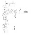
- FIG. 1is a schematic illustration showing the construction of a preferred embodiment of the present invention which utilizes end-pumping for injecting pump light into the multi-mode fiber.
- FIG. 2is a graph showing the typical autocorrelation of pulses generated by the invention of FIG. 1 .
- FIG. 3is a graph showing the typical pulse spectrum generated by the invention of FIG. 1 .
- FIG. 4is a schematic illustration showing the construction of an alternate preferred embodiment utilizing a side-pumping mechanism for injecting pump light into the multi-mode fiber.
- FIG. 5is a schematic illustration of an alternative embodiment which uses a length of positive dispersion fiber to introduce chirped pulses into the cavity.
- FIG. 6is a schematic illustration of an alternative embodiment which uses chirped fiber gratings with negative dispersion in the laser cavity to produce high-energy, near bandwidth-limited pulses.
- FIGS. 7 a and 7 billustrate polarization-maintaining multi-mode fiber cross sections which may be used to construct environmentally stable cavities in the absence of Faraday rotators.
- FIG. 8is a schematic illustration of an alternative embodiment which utilizes one of the fibers illustrated in FIGS. 7 a and 7 b.
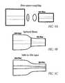
- FIGS. 9 a , 9 b and 9 cillustrate the manner is which the fundamental mode of the multi-mode fibers of the present invention may be matched to the mode of a singe mode fiber.
- Theseinclude a bulk optic imaging system, as shown in FIG. 9 a , a multi-mode to single-mode splice, as shown in FIG. 9 b , and a tapered section of multi-mode fiber, as illustrated in FIG. 9 c.
- FIG. 10is a schematic illustration of an alternative embodiment in which a fiber grating is used to predominantly reflect the fundamental mode of a multi-mode fiber.
- FIG. 11is a schematic illustration of an alternative embodiment in which active or active-passive modelocking is used to mode-lock the multi-mode laser.
- FIG. 1Aillustrates the mode-locked laser cavity 11 of this invention which uses a length of multi-mode amplifying fiber 13 within the cavity to produce ultra-short, high-power optical pulses.
- “ultra-short”means a pulse width below 100 ps.
- the fiber 13in the example shown, is a 1.0 m length of non-birefringent Yb 3+ /Er 3+ -doped multi-mode fiber.
- a fiberis considered multi-mode when the V-value exceeds 2.41, i.e., when modes in addition to the fundamental mode can propagate in the optical fiber.
- This fiberis coiled onto a drum with a diameter of 5 cm, though bend diameters as small as 1.5 cm, or even smaller, may be used without inhibiting mode-locking. Due to the Er 3+ doping, the fiber core in this example has an absorption of approximately 40 dB/m at a wavelength of 1.53 ⁇ m. The Yb 3+ co-doping produces an average absorption of 4.3 dB/m inside the cladding at a wavelength of 980 nm.
- the fiber 13has a numerical aperture of 0.20 and a core diameter of 16 ⁇ m. The outside diameter of the cladding of the fiber 13 is 200 ⁇ m.
- the fiber 13is coated with a low-index polymer producing a numerical aperture of 0.40 for the cladding.
- a 10 cm length of single-mode Corning Leaf fiber 15is thermally tapered to produce a core diameter of approximately 14 ⁇ m to ensure an optimum operation as a mode filter, and this length is fusion spliced onto a first end 17 of the multi-mode fiber 13 .
- the cavity 11is formed between a first mirror 19 and a second mirror 21 . It will be recognized that other cavity configurations for recirculating pulses are well known, and may be used.
- the mirrors 19 , 21define an optical axis 23 along which the cavity elements are aligned.
- the cavity 11further includes a pair of Faraday rotators 25 , 27 to compensate for linear phase drifts between the polarization eigenmodes of the fiber, thereby assuring that the cavity remains environmentally stable.
- the phrase “environmentally stable”refers to a pulse source which is substantially immune to a loss of pulse generation due to environmental influences such as temperature drifts and which is, at most, only slightly sensitive to pressure variations.
- the use of Faraday Rotators for assuring environmental stabilityis explained in more detail in U.S. Pat. No. 5,689,519 which has been incorporated by reference herein.
- a polarization beam-splitter 29 on the axis 23 of the cavity 11ensures single-polarization operation of the cavity 11 , and provides the output 30 from the cavity.
- a half-wave plate 31 and a quarter-wave plate 33are used to introduce linear phase delays within the cavity, providing polarization control to permit optimization of polarization evolution within the cavity 11 for modelocking.
- the cavity 11is formed as a Fabry-Perot cavity by including a saturable absorber 35 at the end of the cavity proximate the mirror 19 .
- the saturable absorber 35is preferably grown as a 0.75 ⁇ m thick layer of InGaAsP on one surface of a substrate.
- the band-edge of the InGaAsP saturable absorber 39is preferably chosen to be 1.56 ⁇ m, the carrier life-time is typically 5 ps and the saturation energy density is 100 MW/cm 2 .
- the substrate supporting the saturable absorber 35comprises high-quality anti-reflection-coated InP 37 , with the anti-reflection-coated surface 39 facing the open end of the cavity 11 .
- the InP substrateis transparent to single-photon absorption of the signal light at 1.56 ⁇ m, however two photon absorption occurs.
- This two-photon absorber 39is used as a nonlinear power limiter to protect the saturable absorber 35 .
- the mirror 19 in this exemplary embodimentis formed by depositing a gold-film onto the surface of the InGaAsP saturable absorber 35 opposite the two photon absorber 39 .
- the combined structure of the saturable absorber 35 , two photon absorber 37 and mirror 19provides a reflectivity of 50% at 1.56 ⁇ m.
- the surface of the gold-film mirror 19 opposite the saturable absorber 35is attached to a sapphire window 41 for heat-sinking the combined absorber/mirror assembly.
- the laser beam from the fiber 15is collimated by a lens 43 and refocused, after rotation by the Faraday rotator 25 , by a lens 45 onto the anti-reflection-coated surface 39 of the two-photon absorber 37 .
- the spot size of the laser beam on the saturable absorber 35may be adjusted by varying the position of the lens 45 or by using lenses with different focal lengths. Other focusing lenses 47 and 49 in the cavity 11 aid in better imaging the laser signal onto the multi-mode fiber 13 .
- Pump light source 51such as a laser source, with a wavelength near 980 nm and output power of 5 W, is directed through a fiber bundle 57 with an outside diameter of 375 ⁇ m.
- This pump lightis injected into the end 53 of the multi-mode fiber 13 opposite the single-mode fiber 17 .
- the pump lightis coupled into the cavity 11 via a pump signal injector 55 , such as a dichroic beam-splitter for 980/1550 nm.
- Lenses 47 and 48are optimized for coupling of the pump power from the fiber bundle 57 into the cladding of the multi-mode fiber.
- the M 2 -value of the beam at the output 30 of this exemplary embodimentis typically approximately 1.2. Assuming the deterioration of the M 2 -value is mainly due to imperfect splicing between the multi-mode fiber 13 and the single-mode mode-filter fiber 15 , it can be estimated that the single-mode mode-filter fiber 15 excited the fundamental mode of the multi-mode fiber 13 with an efficiency of approximately 90%
- Mode-lockingmay be obtained by optimizing the focussing of the laser beam on the saturable absorber 35 and by optimizing the orientation of the intra-cavity waveplates 31 , 33 to permit some degree of nonlinear polarization evolution.
- the mode-locked operation of a multi-mode fiber laser system without nonlinear polarization evolutioncan also be accomplished by minimizing the amount of mode-mixing in the multi-mode fiber 13 and by an optimization of the saturable absorber 35 .
- the pulses which are generated by the exemplary embodiment of FIG. 1will have a repetition rate of 66.7 MHz, with an average output power of 300 mW at a wavelength of 1.535 ⁇ m, giving a pulse energy of 4.5 nJ.
- a typical autocorrelation of the pulsesis shown in FIG. 2 .
- a typical FWHM pulse width of 360 fsec (assuming a sech 2 pulse shape)is generated.
- the corresponding pulse spectrumis shown in FIG. 3 .
- the autocorrelation widthis within a factor of 1.5 of the bandwidth limit as calculated from the pulse spectrum, which indicates the relatively high quality of the pulses.
- the pulse spectrumis strongly modulated and therefore the autocorrelation displays a significant amount of energy in a pulse pedestal. It can be estimated that the amount of energy in the pedestal is about 50%, which in turn gives a pulse peak power of 6 KW, about 6 times larger than what is typically obtained with single-mode fibers at a similar pulse repetition rate.
- the modulation on the obtained pulse spectrum as well as the amount of generated pedestalis dependent on the alignment of the mirror 21 .
- optimized mode-matching of the optical beam back into the fundamental mode of the multi-mode fiberleads to the best laser stability and a reduction in the amount of pedestal and pulse spectrum modulation.
- optimized pulse qualitycan be obtained by improving the splice between the single-mode filter fiber 15 and the multi-mode fiber 13 . From simple overlap integrals it can be calculated that an optimum tapered section of Corning SMF-28 fiber 15 will lead to an excitation of the fundamental mode in the multi-mode fiber 13 with an efficiency of 99%. Thus any signal in higher-order modes can be reduced to about 1% in an optimized system.
- FIG. 4An alternate embodiment of the invention is illustrated in FIG. 4 . As indicated by the identical elements and reference numbers, most of the cavity arrangement in this figure is identical to that shown in FIG. 1 .
- This embodimentprovides a highly integrated cavity 59 by employing a side-pumping mechanism for injecting pump light into the multi-mode fiber 13 .
- a pair of fiber couplers 61 , 63as are well known in the art, inject light from a respective pair of fiber bundles 65 and 67 into the cladding of the multi-mode fiber 13 .
- the fiber bundlesare similar to bundle 57 shown in FIG. 1 , and convey light from a pair of pump sources 69 and 71 , respectively.
- the fiber bundles 65 , 67 and couplers 61 , 63may be replaced with V-groove light injection into the multi-mode fiber cladding in a manner well known in the art.
- a saturable absorber 73may comprise the elements 35 , 37 , 39 and 41 shown in FIG. 1 , or may be of any other well known design, so long as it provides a high damage threshold.
- the laser cavity 75includes a positive dispersion element.
- a section of single-mode positive dispersion fiber 77is mounted between the second mirror 21 and the lens 49 .
- a section of positive dispersion fibercould be spliced onto the end 53 of the multi-mode fiber 13 , or the end of the single-mode mode-filter 15 facing the lens 43 .
- Positive dispersion fiberstypically have a small core area, and may limit the obtainable pulse energy from a laser.
- the embodiment shown in FIG. 5serves to reduce the peak power injected into the positive dispersion fiber 77 , and thus maximize the pulse energy output. This is accomplished by extracting, at the polarization beam splitter 29 , as much as 90-99% of the light energy.
- the total dispersion inside the cavitymay be adjusted to be zero to generate high-power pulses with a larger bandwidth.
- the total cavity dispersionmay be positive, chirped pulses with significantly increased pulse energies may be generated by the laser.
- the use of two single-mode mode-filter fibers 15 , 77is also beneficial in simplifying the alignment of the laser. Typically, to minimize modal speckle, broad bandwidth optical signals need to be used for aligning the mode-filter fibers with the multi-mode fiber.
- the use of two mode-filter fibers 15 , 77allows the use of amplified spontaneous emission signals generated directly in the multi-mode fiber for an iterative alignment of both mode-filters 15 , 77 .
- the chirped pulses generated in the cavity 75 with overall positive dispersionmay be compressed down to approximately the bandwidth limit at the frequency doubled wavelength by employing chirped periodically poled LiNbO 3 79 for sum-frequency generation, in a manner well known in the art.
- the chirped periodically poled LiNbO 3 79receives the cavity output from the polarization beam splitter 29 through an optical isolator 81 .
- optical isolator 81In this case, due to the high power capabilities of multi-mode fiber oscillators, higher frequency-doubling conversion efficiencies occur compared to those experienced with single-mode fiber oscillators.
- bulk-optics dispersion compensating elementsmay be used in place of the chirped periodically poled LiNbO 3 79 for compressing the chirped pulses down to the bandwidth limit.
- any nonlinear optical mixing techniquesuch as frequency doubling, Raman generation, four-wave mixing, etc. may be used in place of the chirped periodically poled LiNbO 3 79 to frequency convert the output of the multi-mode oscillator fiber 13 to a different wavelength.
- the conversion efficiency of these nonlinear optical mixing processesis generally proportional to the light intensity or light intensity squared.
- the small residual pedestal present in a multi-mode oscillatorwould be converted with greatly reduced efficiency compared to the central main pulse and hence much higher quality pulses may be obtained.
- very high-energy optical pulsesmay also be obtained by inserting a chirped fiber grating such as a Bragg grating 83 , with negative dispersion, into the cavity 85 .
- a chirped fiber gratingsuch as a Bragg grating 83
- Such a systemtypically produces ps length, high-energy, approximately bandwidth-limited pulses. Due to the multi-mode fiber used, much greater peak powers compared to single-mode fiber oscillators are generated.
- the fiber grating 83is inserted after the polarization beam splitter 29 to obtain an environmentally-stable cavity even in the presence of nonpolarization maintaining multi-mode fiber 13 .
- Polarization-maintaining multi-mode optical fibermay be constructed by using an elliptical fiber core or by attaching stress-producing regions to the multi-mode fiber cladding. Examples of such fiber cross-sections are shown in FIGS. 7 a and 7 b , respectively.
- Polarization-maintaining multi-mode fiberallows the construction of environmentally stable cavities in the absence of Faraday rotators. An example of such a design is shown in FIG. 8 in this case, the output of the cavity 87 is provided by using a partially-reflecting mirror 89 at one end of the cavity 87 , in a manner well known in this art.
- the multi-mode fiber 13either in the form shown in one for FIG. 7 a and FIG. 7 b or in a non-polarization maintaining form may be tapered to an outside diameter of 70 ⁇ m. This produces an inside core diameter of 5.6 ⁇ m and ensures single mode operation of the multi-mode fiber at the tapered end.
- the single-mode of the multi-mode fibermay be excited with nearly 100% efficiency.
- a graphic representation of the three discussed methods for excitation of the fundamental mode in an multi-mode fiber 13 with a single-mode fiber mode-filter 15is shown in FIGS. 9 a , 9 b and 9 c , respectively.
- the implementation in a cavity designis not shown separately, but the splice between the single-mode fiber 15 and the multi-mode fiber 15 shown in any of the disclosed embodiments may be constructed with any of the three alternatives shown in these figures.
- FIG. 10shows an additional embodiment of the invention.
- fiber gratingssuch as a Bragg grating directly written into the multi-mode fiber 13 is used to predominantly reflect the fundamental mode of the multi-mode fiber 13 .
- Light from the pump 51is injected through the fiber grating 97 to facilitate a particularly simple cavity design 99 .
- Both chirped fiber gratings 97 as well as unchirped gratingscan be implemented.
- Narrow bandwidth (chirped or unchirped) gratingsfavor the oscillation of pulses with a bandwidth smaller than the grating bandwidth.
- an active-passive mode-locked systemcould comprise an optical frequency or amplitude modulator (as the active mode-locking mechanism) in conjunction with nonlinear polarization evolution (as the passive mode-locking mechanism) to produce short optical pulses at a fixed repetition rate without a saturable absorber.
- a diagram of a mode-locked multi-mode fiber 13 with a optical mode-locking mechanism 101is shown in FIG. 11 .
- an optical filter 103which can be used to enhance the performance of the mode-locked laser 105 .
- the cavity designs described hereinare exemplary of the preferred embodiments of this invention. Other variations are obvious from the previous discussions.
- optical modulators, optical filters, saturable absorbers and a polarization control elementsare conveniently inserted at either cavity end.
- output couplingcan be extracted at an optical mirror, a polarization beam splitter or also from an optical fiber coupler attached to the single-mode fiber filter 15 .
- the pump powermay also be coupled into the multi-mode fiber 13 from either end of the multi-mode fiber 13 or through the side of the multi-mode fiber 13 in any of the cavity configurations discussed.
- all the discussed cavitiesmay be operated with any amount of dispersion.
- Chirped and unchirped gratingsmay be implemented at either cavity end to act as optical filters and also to modify the dispersion characteristics of the cavity.
Landscapes
- Physics & Mathematics (AREA)
- Electromagnetism (AREA)
- Engineering & Computer Science (AREA)
- Optics & Photonics (AREA)
- Plasma & Fusion (AREA)
- General Physics & Mathematics (AREA)
- Microelectronics & Electronic Packaging (AREA)
- Chemical & Material Sciences (AREA)
- Materials Engineering (AREA)
- Nanotechnology (AREA)
- Lasers (AREA)
Abstract
Description
This application is a continuation application of U.S. application Ser. No. 09/199,728 filed on Nov. 25, 1998 now U.S. Pat. No. 6,275,512.
The present invention relates to the amplification of single mode light pulses in multi-mode fiber amplifiers, and more particularly to the use of multi-mode amplifying fibers to increase peak pulse power in a mode-locked laser pulse source used for generating ultra-short optical pulses.
Background Relating to Optical Amplifiers
Single-mode rare-earth-doped optical fiber amplifiers have been widely used for over a decade to provide diffraction-limited optical amplification of optical pulses. Because single mode fiber amplifiers generate very low noise levels, do not induce modal dispersion, and are compatible with single mode fiber optic transmission lines, they have been used almost exclusively in telecommunication applications.
The amplification of high peak-power pulses in a diffraction-limited optical beam in single-mode optical fiber amplifiers is generally limited by the small fiber core size that needs to be employed to ensure single-mode operation of the fiber. In general the onset of nonlinearities such as self-phase modulation lead to severe pulse distortions once the integral of the power level present inside the fiber with the propagation length exceeds a certain limiting value. For a constant peak power P inside the fiber, the tolerable amount of self-phase modulation Φn1is given by
- where A is the area of the fundamental mode in the fiber, λ is the operation wavelength, L is the fiber length and n2=3.2×10⁻²⁰m2/W is the nonlinear refractive index in silica optical fibers.
As an alternative to single-mode amplifiers, amplification in multi-mode optical fibers has been considered. However, in general, amplification experiments in multi-mode optical fibers have led to non-diffraction-limited outputs as well as unacceptable pulse broadening due to modal dispersion, since the launch conditions into the multi-mode optical fiber and mode-coupling in the multi-mode fiber have not been controlled.
Amplified spontaneous emission in a multi-mode fiber has been reduced by selectively exciting active ions close to the center of the fiber core or by confining the active ions to the center of the fiber core. U.S. Pat. No. 5,187,759, hereby incorporated herein by reference. Since the overlap of the low-order modes in a multi-mode optical fiber is highest with the active ions close to the center of the fiber core, any amplified spontaneous emission will then also be predominantly generated in low-order modes of the multi-mode fiber. As a result, the total amount of amplified spontaneous emission can be reduced in the multi-mode fiber, since no amplified spontaneous emission is generated in high-order modes.
As an alternative for obtaining high-power pulses, chirped pulse amplification with chirped fiber Bragg gratings has been employed. One of the limitations of this technique is the relative complexity of the set-up.
More recently, the amplification of pulses to peak powers higher than 10 KW has been achieved in multi-mode fiber amplifiers. See U.S. Pat. No. 5,818,630, entitled Single-Mode Amplifiers and Compressors Based on Multi-Mode Fibers, assigned to the assignee of the present invention, and hereby incorporated herein by reference. As described therein, the peak power limit inherent in single-mode optical fiber amplifiers is avoided by employing the increased area occupied by the fundamental mode within multi-mode fibers. This increased area permits an increase in the energy storage potential of the optical fiber amplifier, allowing higher pulse energies before the onset of undesirable nonlinearities and gain saturation. To accomplish this, that application describes the advantages of concentration of the gain medium in the center of the multi-mode fiber so that the fundamental mode is preferentially amplified. This gain-confinement is utilized to stabilize the fundamental mode in a fiber with a large cross section by gain guiding.
Additionally, that reference describes the writing of chirped fiber Bragg gratings onto multi-mode fibers with reduced mode-coupling to increase the power limits for linear pulse compression of high-power optical pulses. In that system, double-clad multi-mode fiber amplifiers are pumped with relatively large-area high-power semiconductor lasers. Further, the fundamental mode in the multi-mode fibers is excited by employing efficient mode-filters. By further using multi-mode fibers with low mode-coupling, the propagation of the fundamental mode in multi-mode amplifiers over lengths of several meters can be ensured, allowing the amplification of high-power optical pulses in doped multi-mode fiber amplifiers with core diameters of several tens of microns, while still providing a diffraction limited output beam. That system additionally employed cladding pumping by broad area diode array lasers to conveniently excite multi-mode fiber amplifiers.
Background Relating to Modelocked Lasers
Both actively modelocked lasers and passively modelocked lasers are well known in the laser art. For example, compact modelocked lasers have been formed as ultrashort pulse sources using single-mode rare-earth-doped fibers. One particularly useful fiber pulse source is based on Kerr-type passive modelocking. Such pulse sources have been assembled using widely available standard fiber components to provide pulses at the bandwidth limit of rare-earth fiber lasers with GigaHertz repetition rates.
Semiconductor saturable absorbers have recently found applications in the field of passively modelocked, ultrashort pulse lasers. These devices are attractive since they are compact, inexpensive, and can be tailored to a wide range of laser wavelengths and pulsewidths. Quantum well and bulk semiconductor saturable absorbers have also been used to modelock color center lasers
A saturable absorber has an intensity-dependent loss l. The single pass loss of a signal of intensity I through a saturable absorber of thickness d may be expressed as
l=1−exp(−αd)
in which α is the intensity dependent absorption coefficient given by:
α(I)=α0/(1+I/ISAT)
Here α0is the small signal absorption coefficient, which depends upon the material in question. ISATis the saturation intensity, which is inversely proportional to the lifetime (τA) of the absorbing species within the saturable absorber. Thus, saturable absorbers exhibit less loss at higher intensity.
Because the loss of a saturable absorber is intensity dependent, the pulse width of the laser pulses is shortened as they pass through the saturable absorber. How rapidly the pulse width of the laser pulses is shortened is proportional to |dq0/dI|, in which q0is the nonlinear loss:
q0=l(I)−l(I=0)
l(I=0) is a constant (=1−exp(−α0d)) and is known as the insertion loss. As defined herein, the nonlinear loss q0of a saturable absorber decreases (becomes more negative) with increasing intensity I. |dq0/dI| stays essentially constant until I approaches ISAT, becoming essentially zero in the bleaching regime, i.e., when I>>ISAT.
For a saturable absorber to function satisfactorily as a modelocking element, it should have a lifetime (i.e., the lifetime of the upper state of the absorbing species), insertion loss l(I=0), and nonlinear loss q0appropriate to the laser. Ideally, the insertion loss should be low to enhance the laser's efficiency, whereas the lifetime and the nonlinear loss q0should permit self-starting and stable cw modelocking. The saturable absorber's characteristics, as well as laser cavity parameters such as output coupling fraction, residual loss, and lifetime of the gain medium, all play a role in the evolution of a laser from startup to modelocking.
As with single-mode fiber amplifiers, the peak-power of pulses from mode-locked single-mode lasers has been limited by the small fiber core size that has been employed to ensure single-mode operation of the fiber. In addition, in mode-locked single-mode fiber lasers, the roundtrip nonlinear phase delay also needs to be limited to around π to prevent the generation of pulses with a very large temporally extended background, generally referred to as a pedestal. For a standard mode-locked single-mode erbium fiber laser operating at 1.55 μm with a core diameter of 10 μm and a round-trip cavity length of 2 m, corresponding to a pulse repetition rate of 50 MHz, the maximum oscillating peak power is thus about 1 KW.
The long-term operation of mode-locked single-mode fiber lasers is conveniently ensured by employing an environmentally stable cavity as described in U.S. Pat. No. 5,689,519, entitled Environmentally Stable Passively Modelocked Fiber Laser Pulse Source, assigned to the assignee of the present invention, and hereby incorporated herein by reference. The laser described in this reference minimizes environmentally induced fluctuations in the polarization state at the output of the single-mode fiber. In the described embodiments, this is accomplished by including a pair of Faraday rotators at opposite ends of the laser cavity to compensate for linear phase drifts between the polarization eigenmodes of the fiber.
Recently the reliability of high-power single-mode fiber lasers passively mode-locked by saturable absorbers has been greatly improved by implementing nonlinear power limiters by insertion of appropriate semiconductor two-photon absorbers into the cavity, which minimizes the peak power of the damaging Q-switched pulses often observed in the start-up of mode-locking and in the presence of misalignments of the cavity. See U.S. patent application Ser. No. 09/149,369, filed on Sep. 8, 1998, entitled Resonant Fabry-Perot Semiconductor Saturable Absorbers and Two-Photon Absorption Power Limiters, assigned to the assignee of the present invention, and hereby incorporated herein by reference.
To increase the pulse energy available from mode-locked single-mode fiber lasers the oscillation of chirped pulses inside the laser cavity has been employed. M. Hofer et al., Opt. Lett., vol. 17, page 807-809. As a consequence the pulses are temporally extended, giving rise to a significant peak power reduction inside the fiber laser. However, the pulses can be temporally compressed down to approximately the bandwidth limit outside the laser cavity. Due to the resulting high peak power, bulk-optic dispersive delay lines have to be used for pulse compression. For neodymium fiber lasers, pulse widths of the order of 100 fs can be obtained.
The pulse energy from mode-locked single-mode fiber lasers has also been increased by employing chirped fiber gratings. The chirped fiber gratings have a large amount of negative dispersion, broadening the pulses inside the cavity dispersively, which therefore reduces their peak power and also leads to the oscillation of high-energy pulses inside the single-mode fiber lasers.
See U.S. Pat. No. 5,450,427, entitled Technique for the Generation of Optical Pulses in Mode-Locked Lasers by Dispersive Control of the Oscillation Pulse Width, and U.S. Pat. No. 5,627,848, entitled Apparatus for Producing Femtosecond and Picosecond Pulses from Fiber Lasers Cladding Pumped with Broad Area Diode Laser Arrays, both of which are assigned to the assignee of the present invention and hereby incorporated herein by reference. In these systems, the generated pulses are bandwidth-limited, though the typical oscillating pulse widths are of the order of a few ps.
However, though the dispersive broadening of the pulse width oscillating inside a single-mode fiber laser cavity does increase the oscillating pulse energy compared to a ‘standard’ soliton fiber laser, it does not increase the oscillating peak power. The maximum peak power generated with these systems directly from the fiber laser is still limited to around I KW.
Another highly integratable method for increasing the peak power of mode-locked lasers is based on using chirped periodically poled LiNb03 (chirped PPLN). Chirped PPLN permits simultaneous pulse compression and frequency doubling of an optically chirped pulse. See U.S. patent application Ser. No. 08/845,410, filed on Apr. 25, 1997, entitled Use of Aperiodic Quasi-Phase-Matched Gratings in Ultrashort Pulse Sources, assigned to the assignee of the present application, and hereby incorporated herein by reference. However, for chirped PPLN to produce pulse compression from around 3 ps to 300 fs and frequency doubling with high conversion efficiencies, generally peak powers of the order of several KW are required. Such high peak powers are typically outside the range of mode-locked single-mode erbium fiber lasers.
Broad area diode laser arrays have been used for pumping of mode-locked single-mode fiber lasers, where very compact cavity designs were possible. The pump light was injected through a V-groove from the side of double-clad fiber, a technique typically referred to as side-pumping. However, such oscillator designs have also suffered from peak power limitations due to the single-mode structure of the oscillator fiber.
It has also been suggested that a near diffraction-limited output beam can be obtained from a multi-mode fiber laser when keeping the fiber length shorter than 15 mm and selectively providing a maximum amount of feedback for the fundamental mode of the optical fiber. “Efficient laser operation with nearly diffraction-limited output from a diode-pumped heavily Nd-doped multimode fiber”,Optics Letters, Vol. 21, pp. 266-268 (1996) hereby incorporated herein by reference. In this technique, however, severe mode-coupling has been a problem, as the employed multi-mode fibers typically support thousands of modes. Also, only an air-gap between the endface of the multi-mode fiber and a laser mirror has been suggested for mode-selection. Hence, only very poor modal discrimination has been obtained, resulting in poor beam quality.
While the operation of optical amplifiers, especially in the presence of large seed signals, is not very sensitive to the presence of spurious reflections, the stability of mode-locked lasers critically depends on the minimization of spurious reflections. Any stray reflections produce sub-cavities inside an oscillator and result in injection signals for the cw operation of a laser cavity and thus prevent the onset of mode-locking. For solid-state FabryPerot cavities a suppression of intra-cavity reflections to a level <<1% (in intensity) is generally believed to be required to enable the onset of mode-locking.
The intra-cavity reflections that are of concern in standard mode-locked lasers can be thought of as being conceptually equivalent to mode-coupling in multi-mode fibers. Any mode-coupling in multi-mode fibers clearly also produces a sub-cavity with a cw injection signal proportional to the amount of mode-coupling. However, the suppression of mode-coupling to a level of <<I % at any multi-mode fiber discontinuities is very difficult to achieve. Due to optical aberrations, even well corrected optics typically allow the excitation of the fundamental mode in multi-mode fibers only with maximum efficiency of about 95%. Therefore to date, it has been considered that mode-locking of a multi-mode fiber is impossible and no stable operation of a mode-locked multi-mode fiber laser has yet been demonstrated.
This invention overcomes the foregoing difficulties associated with peak power limitations in modelocked lasers, and provides a mode-locked multi-mode fiber laser.
This laser utilizes cavity designs which allow the stable generation of high peak power pulses from mode-locked multi-mode fiber lasers, greatly extending the peak power limits of conventional mode-locked single-mode fiber lasers. Mode-locking may be induced by insertion of a saturable absorber into the cavity and by inserting one or more mode-filters to ensure the oscillation of the fundamental mode in the multi-mode fiber. The probability of damage of the absorber may be minimized by the insertion of an additional semiconductor optical power limiter into the cavity. The shortest pulses may also be generated by taking advantage of nonlinear polarization evolution inside the fiber. The long-term stability of the cavity configuration is ensured by employing an environmentally stable cavity. Pump light from a broad-area diode laser may be delivered into the multi-mode fiber by employing a cladding-pumping technique.
With this invention, a modelocked fiber laser may be constructed to obtain, for example, 360 fsec near-bandwidth-limited pulses with an average power of 300 mW at a repetition rate of 66.7 MHz. The peak power of these exemplary pulses is estimated to be about 6 KW.
The following description of the preferred embodiments of the invention references the appended drawings, in which like elements bear identical reference numbers throughout.
In this exemplary embodiment, thecavity 11 is formed between afirst mirror 19 and asecond mirror 21. It will be recognized that other cavity configurations for recirculating pulses are well known, and may be used. In this example, themirrors optical axis 23 along which the cavity elements are aligned.
Thecavity 11 further includes a pair ofFaraday rotators
A polarization beam-splitter 29 on theaxis 23 of thecavity 11 ensures single-polarization operation of thecavity 11, and provides theoutput 30 from the cavity. A half-wave plate 31 and a quarter-wave plate 33 are used to introduce linear phase delays within the cavity, providing polarization control to permit optimization of polarization evolution within thecavity 11 for modelocking.
To induce mode-locking, thecavity 11 is formed as a Fabry-Perot cavity by including asaturable absorber 35 at the end of the cavity proximate themirror 19. Thesaturable absorber 35 is preferably grown as a 0.75 μm thick layer of InGaAsP on one surface of a substrate. The band-edge of theInGaAsP saturable absorber 39 is preferably chosen to be 1.56 μm, the carrier life-time is typically 5 ps and the saturation energy density is 100 MW/cm2.
In this example, the substrate supporting thesaturable absorber 35 comprises high-quality anti-reflection-coatedInP 37, with the anti-reflection-coatedsurface 39 facing the open end of thecavity 11. The InP substrate is transparent to single-photon absorption of the signal light at 1.56 μm, however two photon absorption occurs. This two-photon absorber 39 is used as a nonlinear power limiter to protect thesaturable absorber 35.
Themirror 19 in this exemplary embodiment is formed by depositing a gold-film onto the surface of theInGaAsP saturable absorber 35 opposite the twophoton absorber 39. The combined structure of thesaturable absorber 35, twophoton absorber 37 andmirror 19 provides a reflectivity of 50% at 1.56 μm. The surface of the gold-film mirror 19 opposite thesaturable absorber 35 is attached to asapphire window 41 for heat-sinking the combined absorber/mirror assembly.
The laser beam from thefiber 15 is collimated by alens 43 and refocused, after rotation by theFaraday rotator 25, by alens 45 onto the anti-reflection-coatedsurface 39 of the two-photon absorber 37. The spot size of the laser beam on thesaturable absorber 35 may be adjusted by varying the position of thelens 45 or by using lenses with different focal lengths. Other focusinglenses cavity 11 aid in better imaging the laser signal onto themulti-mode fiber 13.
Light from a Pumplight source 51, such as a laser source, with a wavelength near 980 nm and output power of 5 W, is directed through afiber bundle 57 with an outside diameter of 375 μm. This pump light is injected into theend 53 of themulti-mode fiber 13 opposite the single-mode fiber 17. The pump light is coupled into thecavity 11 via apump signal injector 55, such as a dichroic beam-splitter for 980/1550 nm.Lenses fiber bundle 57 into the cladding of the multi-mode fiber.
The M2-value of the beam at theoutput 30 of this exemplary embodiment is typically approximately 1.2. Assuming the deterioration of the M2-value is mainly due to imperfect splicing between themulti-mode fiber 13 and the single-mode mode-filter fiber 15, it can be estimated that the single-mode mode-filter fiber 15 excited the fundamental mode of themulti-mode fiber 13 with an efficiency of approximately 90%
Mode-locking may be obtained by optimizing the focussing of the laser beam on thesaturable absorber 35 and by optimizing the orientation of theintra-cavity waveplates multi-mode fiber 13 and by an optimization of thesaturable absorber 35.
The pulses which are generated by the exemplary embodiment ofFIG. 1 will have a repetition rate of 66.7 MHz, with an average output power of 300 mW at a wavelength of 1.535 μm, giving a pulse energy of 4.5 nJ. A typical autocorrelation of the pulses is shown inFIG. 2 . A typical FWHM pulse width of 360 fsec (assuming a sech2pulse shape) is generated. The corresponding pulse spectrum is shown inFIG. 3 . The autocorrelation width is within a factor of 1.5 of the bandwidth limit as calculated from the pulse spectrum, which indicates the relatively high quality of the pulses.
Due to the multi-mode structure of the oscillator, the pulse spectrum is strongly modulated and therefore the autocorrelation displays a significant amount of energy in a pulse pedestal. It can be estimated that the amount of energy in the pedestal is about 50%, which in turn gives a pulse peak power of 6 KW, about 6 times larger than what is typically obtained with single-mode fibers at a similar pulse repetition rate.
Neglecting the amount of self-phase modulation in one pass through themulti-mode fiber 13 and any self-phase modulation in the mode-filter 15, and assuming a linear increase of pulse power in themulti-mode fiber 13 in the second pass, and assuming an effective fundamental mode area in themulti-mode fiber 13 of 133 μm2, the nonlinear phase delay in the multi-mode oscillator is calculated from the first equation above as Φn1=1.45π, which is close to the expected maximum typical nonlinear delay of passively mode-locked lasers.
The modulation on the obtained pulse spectrum as well as the amount of generated pedestal is dependent on the alignment of themirror 21. Generally, optimized mode-matching of the optical beam back into the fundamental mode of the multi-mode fiber leads to the best laser stability and a reduction in the amount of pedestal and pulse spectrum modulation. For this reason, optimized pulse quality can be obtained by improving the splice between the single-mode filter fiber 15 and themulti-mode fiber 13. From simple overlap integrals it can be calculated that an optimum tapered section of Corning SMF-28fiber 15 will lead to an excitation of the fundamental mode in themulti-mode fiber 13 with an efficiency of 99%. Thus any signal in higher-order modes can be reduced to about 1% in an optimized system.
An alternate embodiment of the invention is illustrated inFIG. 4 . As indicated by the identical elements and reference numbers, most of the cavity arrangement in this figure is identical to that shown inFIG. 1 . This embodiment provides a highly integratedcavity 59 by employing a side-pumping mechanism for injecting pump light into themulti-mode fiber 13. A pair offiber couplers fiber bundles multi-mode fiber 13. The fiber bundles are similar to bundle57 shown inFIG. 1 , and convey light from a pair ofpump sources couplers saturable absorber 73 may comprise theelements FIG. 1 , or may be of any other well known design, so long as it provides a high damage threshold.
In another alternate embodiment of the invention, Illustrated inFIG. 5 , thelaser cavity 75 includes a positive dispersion element. As WithFIG. 4 , like reference numbers inFIG. 5 identify elements described in detail with reference toFIG. 1 . In this embodiment, a section of single-modepositive dispersion fiber 77 is mounted between thesecond mirror 21 and thelens 49. In a similar manner, a section of positive dispersion fiber could be spliced onto theend 53 of themulti-mode fiber 13, or the end of the single-mode mode-filter 15 facing thelens 43. Positive dispersion fibers typically have a small core area, and may limit the obtainable pulse energy from a laser. The embodiment shown inFIG. 5 serves to reduce the peak power injected into thepositive dispersion fiber 77, and thus maximize the pulse energy output. This is accomplished by extracting, at thepolarization beam splitter 29, as much as 90-99% of the light energy.
In the embodiment ofFIG. 5 , the total dispersion inside the cavity may be adjusted to be zero to generate high-power pulses with a larger bandwidth. Alternatively, by adjusting the total cavity dispersion to be positive, chirped pulses with significantly increased pulse energies may be generated by the laser.
The use of two single-mode mode-filter fibers filter fibers filters
The chirped pulses generated in thecavity 75 with overall positive dispersion may be compressed down to approximately the bandwidth limit at the frequency doubled wavelength by employing chirped periodically poledLiNbO 379 for sum-frequency generation, in a manner well known in the art. The chirped periodically poledLiNbO 379 receives the cavity output from thepolarization beam splitter 29 through anoptical isolator 81. In this case, due to the high power capabilities of multi-mode fiber oscillators, higher frequency-doubling conversion efficiencies occur compared to those experienced with single-mode fiber oscillators. Alternatively, bulk-optics dispersion compensating elements may be used in place of the chirped periodically poledLiNbO 379 for compressing the chirped pulses down to the bandwidth limit.
Generally, any nonlinear optical mixing technique such as frequency doubling, Raman generation, four-wave mixing, etc. may be used in place of the chirped periodically poledLiNbO 379 to frequency convert the output of themulti-mode oscillator fiber 13 to a different wavelength. Moreover, the conversion efficiency of these nonlinear optical mixing processes is generally proportional to the light intensity or light intensity squared. Thus, the small residual pedestal present in a multi-mode oscillator would be converted with greatly reduced efficiency compared to the central main pulse and hence much higher quality pulses may be obtained.
As shown in the alternate embodiment ofFIG. 6 , very high-energy optical pulses may also be obtained by inserting a chirped fiber grating such as a Bragg grating83, with negative dispersion, into the cavity85. Such a system typically produces ps length, high-energy, approximately bandwidth-limited pulses. Due to the multi-mode fiber used, much greater peak powers compared to single-mode fiber oscillators are generated. Here the fiber grating83 is inserted after thepolarization beam splitter 29 to obtain an environmentally-stable cavity even in the presence of nonpolarization maintainingmulti-mode fiber 13.
In each of the embodiments of this invention, it is advantageous to minimize saturation of themulti-mode fiber amplifier 13 by amplified spontaneous emission generated in higher-order modes. This may be accomplished by confining the rare-earth doping centrally within a fraction of the core diameter.
Polarization-maintaining multi-mode optical fiber may be constructed by using an elliptical fiber core or by attaching stress-producing regions to the multi-mode fiber cladding. Examples of such fiber cross-sections are shown inFIGS. 7 aand7b, respectively. Polarization-maintaining multi-mode fiber allows the construction of environmentally stable cavities in the absence of Faraday rotators. An example of such a design is shown inFIG. 8 in this case, the output of thecavity 87 is provided by using a partially-reflectingmirror 89 at one end of thecavity 87, in a manner well known in this art.
To ensure optimum matching of the fundamental mode of themulti-mode fiber 13 to the mode of the single-mode mode-filter fiber 15 in each of the embodiments of this invention, either a bulk optic imaging system, a splice between themulti-mode fiber 13 and the single-mode fiber 15, or a tapered section of themulti-mode fiber 13 may be used. For example, themulti-mode fiber 13, either in the form shown in one forFIG. 7 aandFIG. 7 bor in a non-polarization maintaining form may be tapered to an outside diameter of 70 μm. This produces an inside core diameter of 5.6 μm and ensures single mode operation of the multi-mode fiber at the tapered end. By further employing an adiabatic taper, the single-mode of the multi-mode fiber may be excited with nearly 100% efficiency. A graphic representation of the three discussed methods for excitation of the fundamental mode in anmulti-mode fiber 13 with a single-mode fiber mode-filter 15 is shown inFIGS. 9 a,9band9c, respectively. The implementation in a cavity design is not shown separately, but the splice between the single-mode fiber 15 and themulti-mode fiber 15 shown in any of the disclosed embodiments may be constructed with any of the three alternatives shown in these figures.
Finally, instead of passive mode-locking, active mode-locking or active-passive mode-locking techniques may be used to mode-lock multi-mode fibers. For example, an active-passive mode-locked system could comprise an optical frequency or amplitude modulator (as the active mode-locking mechanism) in conjunction with nonlinear polarization evolution (as the passive mode-locking mechanism) to produce short optical pulses at a fixed repetition rate without a saturable absorber. A diagram of a mode-lockedmulti-mode fiber 13 with a optical mode-lockingmechanism 101 is shown inFIG. 11 . Also shown is anoptical filter 103, which can be used to enhance the performance of the mode-lockedlaser 105.
Generally, the cavity designs described herein are exemplary of the preferred embodiments of this invention. Other variations are obvious from the previous discussions. In particular, optical modulators, optical filters, saturable absorbers and a polarization control elements are conveniently inserted at either cavity end. Equally, output coupling can be extracted at an optical mirror, a polarization beam splitter or also from an optical fiber coupler attached to the single-mode fiber filter 15. The pump power may also be coupled into themulti-mode fiber 13 from either end of themulti-mode fiber 13 or through the side of themulti-mode fiber 13 in any of the cavity configurations discussed. Equally, all the discussed cavities may be operated with any amount of dispersion. Chirped and unchirped gratings may be implemented at either cavity end to act as optical filters and also to modify the dispersion characteristics of the cavity.
Claims (8)
1. A laser, comprising:
a cavity which repeatedly passes light energy along a cavity axis;
a length of multi-mode optical fiber having a cladding and doped with a gain medium and positioned along said cavity axis;
a pump coupled to said cladding for exciting said gain medium; and
an optical guide positioned on said cavity axis which confines the light amplified by said multi-mode optical fiber to preferentially the fundamental mode of said multi-mode optical fiber.
2. A laser as defined inclaim 1 additionally comprising a mode locking mechanism positioned on said cavity axis, wherein said mode locking mechanism comprises a passive mode locking element.
3. A laser as defined inclaim 2 wherein said passive mode locking element comprises a saturable absorber.
4. A laser as defined inclaim 3 wherein said saturable absorber comprises InGaAsP.
5. A laser as defined inclaim 3 additionally comprising a power limiter for protecting said saturable absorber.
6. A laser as defined inclaim 5 wherein said power limiter comprises a two photon absorber.
7. A method, comprising:
circulating light energy within a laser cavity;
amplifying said light energy within said laser cavity in a bent multi-mode fiber; and
confining said light energy within said laser cavity substantially to the fundamental mode of said multi-mode fiber.
8. A method as defined inclaim 7 additionally comprising mode locking said light energy.
Priority Applications (8)
| Application Number | Priority Date | Filing Date | Title |
|---|---|---|---|
| US09/785,944US8873593B2 (en) | 1998-11-25 | 2001-02-16 | Mode-locked multi-mode fiber laser pulse source |
| US10/424,220US8761211B2 (en) | 1998-11-25 | 2003-04-25 | Multi-mode fiber amplifier |
| US10/850,509US20050008044A1 (en) | 1998-11-25 | 2004-05-20 | Mode-locked multi-mode fiber laser pulse source |
| US14/174,269US9570880B2 (en) | 1998-11-25 | 2014-02-06 | Multi-mode fiber amplifier |
| US14/223,287US9595802B2 (en) | 1998-11-25 | 2014-03-24 | Multi-mode fiber amplifier |
| US14/517,107US9153929B2 (en) | 1998-11-25 | 2014-10-17 | Mode-locked multi-mode fiber laser pulse source |
| US14/853,135US9450371B2 (en) | 1998-11-25 | 2015-09-14 | Mode-locked multi-mode fiber laser pulse source |
| US15/235,239US20160352063A1 (en) | 1998-11-25 | 2016-08-12 | Mode-locked multi-mode fiber laser pulse source |
Applications Claiming Priority (2)
| Application Number | Priority Date | Filing Date | Title |
|---|---|---|---|
| US09/199,728US6275512B1 (en) | 1998-11-25 | 1998-11-25 | Mode-locked multimode fiber laser pulse source |
| US09/785,944US8873593B2 (en) | 1998-11-25 | 2001-02-16 | Mode-locked multi-mode fiber laser pulse source |
Related Parent Applications (1)
| Application Number | Title | Priority Date | Filing Date |
|---|---|---|---|
| US09/199,728ContinuationUS6275512B1 (en) | 1998-11-25 | 1998-11-25 | Mode-locked multimode fiber laser pulse source |
Related Child Applications (2)
| Application Number | Title | Priority Date | Filing Date |
|---|---|---|---|
| US10/424,220ContinuationUS8761211B2 (en) | 1998-11-25 | 2003-04-25 | Multi-mode fiber amplifier |
| US14/517,107ContinuationUS9153929B2 (en) | 1998-11-25 | 2014-10-17 | Mode-locked multi-mode fiber laser pulse source |
Publications (2)
| Publication Number | Publication Date |
|---|---|
| US20010024458A1 US20010024458A1 (en) | 2001-09-27 |
| US8873593B2true US8873593B2 (en) | 2014-10-28 |
Family
ID=22738775
Family Applications (9)
| Application Number | Title | Priority Date | Filing Date |
|---|---|---|---|
| US09/199,728Expired - LifetimeUS6275512B1 (en) | 1998-11-25 | 1998-11-25 | Mode-locked multimode fiber laser pulse source |
| US09/785,944Active2029-01-31US8873593B2 (en) | 1998-11-25 | 2001-02-16 | Mode-locked multi-mode fiber laser pulse source |
| US10/424,220Expired - Fee RelatedUS8761211B2 (en) | 1998-11-25 | 2003-04-25 | Multi-mode fiber amplifier |
| US10/850,509AbandonedUS20050008044A1 (en) | 1998-11-25 | 2004-05-20 | Mode-locked multi-mode fiber laser pulse source |
| US14/174,269Expired - Fee RelatedUS9570880B2 (en) | 1998-11-25 | 2014-02-06 | Multi-mode fiber amplifier |
| US14/223,287Expired - Fee RelatedUS9595802B2 (en) | 1998-11-25 | 2014-03-24 | Multi-mode fiber amplifier |
| US14/517,107Expired - Fee RelatedUS9153929B2 (en) | 1998-11-25 | 2014-10-17 | Mode-locked multi-mode fiber laser pulse source |
| US14/853,135Expired - Fee RelatedUS9450371B2 (en) | 1998-11-25 | 2015-09-14 | Mode-locked multi-mode fiber laser pulse source |
| US15/235,239AbandonedUS20160352063A1 (en) | 1998-11-25 | 2016-08-12 | Mode-locked multi-mode fiber laser pulse source |
Family Applications Before (1)
| Application Number | Title | Priority Date | Filing Date |
|---|---|---|---|
| US09/199,728Expired - LifetimeUS6275512B1 (en) | 1998-11-25 | 1998-11-25 | Mode-locked multimode fiber laser pulse source |
Family Applications After (7)
| Application Number | Title | Priority Date | Filing Date |
|---|---|---|---|
| US10/424,220Expired - Fee RelatedUS8761211B2 (en) | 1998-11-25 | 2003-04-25 | Multi-mode fiber amplifier |
| US10/850,509AbandonedUS20050008044A1 (en) | 1998-11-25 | 2004-05-20 | Mode-locked multi-mode fiber laser pulse source |
| US14/174,269Expired - Fee RelatedUS9570880B2 (en) | 1998-11-25 | 2014-02-06 | Multi-mode fiber amplifier |
| US14/223,287Expired - Fee RelatedUS9595802B2 (en) | 1998-11-25 | 2014-03-24 | Multi-mode fiber amplifier |
| US14/517,107Expired - Fee RelatedUS9153929B2 (en) | 1998-11-25 | 2014-10-17 | Mode-locked multi-mode fiber laser pulse source |
| US14/853,135Expired - Fee RelatedUS9450371B2 (en) | 1998-11-25 | 2015-09-14 | Mode-locked multi-mode fiber laser pulse source |
| US15/235,239AbandonedUS20160352063A1 (en) | 1998-11-25 | 2016-08-12 | Mode-locked multi-mode fiber laser pulse source |
Country Status (3)
| Country | Link |
|---|---|
| US (9) | US6275512B1 (en) |
| JP (1) | JP4668378B2 (en) |
| DE (2) | DE19956739B4 (en) |
Cited By (2)
| Publication number | Priority date | Publication date | Assignee | Title |
|---|---|---|---|---|
| US9153929B2 (en) | 1998-11-25 | 2015-10-06 | Imra America, Inc. | Mode-locked multi-mode fiber laser pulse source |
| US9609732B2 (en) | 2006-03-31 | 2017-03-28 | Energetiq Technology, Inc. | Laser-driven light source for generating light from a plasma in an pressurized chamber |
Families Citing this family (174)
| Publication number | Priority date | Publication date | Assignee | Title |
|---|---|---|---|---|
| US20040036957A1 (en)* | 1997-03-21 | 2004-02-26 | Imra America, Inc. | Microchip-Yb fiber hybrid optical amplifier for micro-machining and marking |
| US7576909B2 (en) | 1998-07-16 | 2009-08-18 | Imra America, Inc. | Multimode amplifier for amplifying single mode light |
| US7656578B2 (en) | 1997-03-21 | 2010-02-02 | Imra America, Inc. | Microchip-Yb fiber hybrid optical amplifier for micro-machining and marking |
| JP2007516600A (en)* | 1997-03-21 | 2007-06-21 | イムラ アメリカ インコーポレイテッド | High energy fiber optic amplifier for picosecond-nanosecond pulses for advanced material processing applications |
| US20020137890A1 (en)* | 1997-03-31 | 2002-09-26 | Genentech, Inc. | Secreted and transmembrane polypeptides and nucleic acids encoding the same |
| US6922495B2 (en)* | 1997-06-16 | 2005-07-26 | Novera Optics, Inc. | Optical fiber cladding with low polarization-dependent coupling |
| US6252892B1 (en) | 1998-09-08 | 2001-06-26 | Imra America, Inc. | Resonant fabry-perot semiconductor saturable absorbers and two photon absorption power limiters |
| US6751388B2 (en)* | 1999-01-13 | 2004-06-15 | The Board Of Trustees Of The Leland Stanford Junior University | Fiber lasers having a complex-valued Vc-parameter for gain-guiding |
| JP4114258B2 (en)* | 1999-01-26 | 2008-07-09 | アイシン精機株式会社 | Multiple pulse light generation method and apparatus |
| US6393035B1 (en)* | 1999-02-01 | 2002-05-21 | Gigatera Ag | High-repetition rate passively mode-locked solid-state laser |
| BE1013518A6 (en)* | 1999-05-03 | 2002-03-05 | Univ Notre Dame De La Paix | Lock-mode laser pulse by combination of non-linear mirror and a limit of intensity. |
| DE19934638B4 (en)* | 1999-07-23 | 2004-07-08 | Jenoptik Ldt Gmbh | Mode-locked solid-state laser with at least one concave folding mirror |
| US7139901B2 (en) | 2000-02-08 | 2006-11-21 | Mips Technologies, Inc. | Extended instruction set for packet processing applications |
| US7190705B2 (en) | 2000-05-23 | 2007-03-13 | Imra America. Inc. | Pulsed laser sources |
| US7088756B2 (en)* | 2003-07-25 | 2006-08-08 | Imra America, Inc. | Polarization maintaining dispersion controlled fiber laser source of ultrashort pulses |
| US6885683B1 (en) | 2000-05-23 | 2005-04-26 | Imra America, Inc. | Modular, high energy, widely-tunable ultrafast fiber source |
| US6650685B2 (en)* | 2000-11-02 | 2003-11-18 | Raytheon Company | Single laser transmitter for Q-switched and mode-locked vibration operation |
| US6954575B2 (en) | 2001-03-16 | 2005-10-11 | Imra America, Inc. | Single-polarization high power fiber lasers and amplifiers |
| EP1402295B1 (en)* | 2001-03-30 | 2008-12-24 | OCG Technology Licensing, LLC | Ring core fiber |
| FR2827969B1 (en)* | 2001-07-26 | 2003-12-19 | Get Enst Bretagne | OPTICAL DEVICE COMPRISING MODE-EXPANDING FIBERS FOR CARRYING OUT AT LEAST ONE OPTICAL FUNCTION, AND OPTICAL SYSTEM THEREOF |
| US7233739B2 (en)* | 2001-10-22 | 2007-06-19 | Patel C Kumar N | Optical bit stream reader system |
| JP4223959B2 (en)* | 2001-11-19 | 2009-02-12 | チラル・フオトニクス・インコーポレーテツド | Chiral fiber laser device and method |
| US6603600B2 (en)* | 2001-11-21 | 2003-08-05 | Coherent, Inc. | Chirped pulse amplification method and apparatus |
| JP2003283016A (en)* | 2002-03-25 | 2003-10-03 | Aisin Seiki Co Ltd | Passive mode-locked fiber laser |
| US6975791B2 (en)* | 2002-07-25 | 2005-12-13 | Ceramoptec Industries, Inc. | Fiber laser pumping device |
| US7103076B2 (en)* | 2002-10-24 | 2006-09-05 | Matsushita Electric Industrial Co., Ltd. | Ultrashort pulsed laser and optical head using the same |
| JP2004146681A (en)* | 2002-10-25 | 2004-05-20 | Sumitomo Electric Ind Ltd | Optical amplification fiber, optical amplification device, light source device, phototherapy device and exposure device |
| US6693931B1 (en)* | 2002-12-27 | 2004-02-17 | Vanderbilt University | Method and system for phase stabilization |
| WO2004066457A1 (en)* | 2003-01-24 | 2004-08-05 | Trumpf, Inc. | Side-pumped fiber laser |
| US7542488B2 (en)* | 2003-01-24 | 2009-06-02 | Trumpf, Inc. | Fiber laser |
| US7046432B2 (en)* | 2003-02-11 | 2006-05-16 | Coherent, Inc. | Optical fiber coupling arrangement |
| US7224518B2 (en)* | 2003-02-25 | 2007-05-29 | Toptica Photonics Ag | Fiber-optic amplification of light pulses |
| US6967767B2 (en)* | 2003-03-18 | 2005-11-22 | Fitel Usa Corp | Swept wavelength broadband Raman pump source |
| US7379643B2 (en)* | 2003-03-21 | 2008-05-27 | Her Majesty The Queen In Right Of Canada As Represented By The Minister Of Industry, Through The Communications Research Centre Canada | Optical fiber sensor based on retro-reflective fiber Bragg gratings |
| KR100487190B1 (en)* | 2003-04-22 | 2005-05-04 | 삼성전자주식회사 | Raman optical amplifier |
| US7295580B2 (en)* | 2003-05-15 | 2007-11-13 | Hrl Laboratories, Llc | Numerical aperture optimization using doped cladding layers |
| US7361171B2 (en) | 2003-05-20 | 2008-04-22 | Raydiance, Inc. | Man-portable optical ablation system |
| US7095772B1 (en) | 2003-05-22 | 2006-08-22 | Research Foundation Of The University Of Central Florida, Inc. | Extreme chirped/stretched pulsed amplification and laser |
| US7113327B2 (en)* | 2003-06-27 | 2006-09-26 | Imra America, Inc. | High power fiber chirped pulse amplification system utilizing telecom-type components |
| US20050024716A1 (en)* | 2003-07-15 | 2005-02-03 | Johan Nilsson | Optical device with immediate gain for brightness enhancement of optical pulses |
| US7367969B2 (en) | 2003-08-11 | 2008-05-06 | Raydiance, Inc. | Ablative material removal with a preset removal rate or volume or depth |
| US20050065502A1 (en)* | 2003-08-11 | 2005-03-24 | Richard Stoltz | Enabling or blocking the emission of an ablation beam based on color of target |
| US7143769B2 (en)* | 2003-08-11 | 2006-12-05 | Richard Stoltz | Controlling pulse energy of an optical amplifier by controlling pump diode current |
| US7115514B2 (en) | 2003-10-02 | 2006-10-03 | Raydiance, Inc. | Semiconductor manufacturing using optical ablation |
| US8921733B2 (en) | 2003-08-11 | 2014-12-30 | Raydiance, Inc. | Methods and systems for trimming circuits |
| US9022037B2 (en) | 2003-08-11 | 2015-05-05 | Raydiance, Inc. | Laser ablation method and apparatus having a feedback loop and control unit |
| US8173929B1 (en) | 2003-08-11 | 2012-05-08 | Raydiance, Inc. | Methods and systems for trimming circuits |
| US7046875B2 (en)* | 2003-10-29 | 2006-05-16 | Itf Technologies Optiques Inc. | Optical coupler comprising multimode fibers and method of making the same |
| US7016573B2 (en)* | 2003-11-13 | 2006-03-21 | Imra America, Inc. | Optical fiber pump multiplexer |
| US20050137657A1 (en)* | 2003-12-23 | 2005-06-23 | Dykaar Douglas R. | Apparatus and method for emitting light to a desired target location |
| US7413847B2 (en) | 2004-02-09 | 2008-08-19 | Raydiance, Inc. | Semiconductor-type processing for solid-state lasers |
| US7711013B2 (en) | 2004-03-31 | 2010-05-04 | Imra America, Inc. | Modular fiber-based chirped pulse amplification system |
| US7804864B2 (en) | 2004-03-31 | 2010-09-28 | Imra America, Inc. | High power short pulse fiber laser |
| KR100628472B1 (en)* | 2004-05-24 | 2006-09-26 | 한국과학기술연구원 | Raman or Erbium fiber lasers using fiber optic gratings and long-range sensors for simultaneous temperature and strain measurements |
| US7570846B2 (en)* | 2004-06-21 | 2009-08-04 | Oree, Advanced Illumination Solutions Inc. | High efficacy waveguide coupler |
| JP2006073970A (en)* | 2004-09-06 | 2006-03-16 | Cyber Laser Kk | Cw deep ultraviolet ray source |
| US7106501B2 (en) | 2004-10-14 | 2006-09-12 | Coherent, Inc. | Fiber amplifier with suppression of amplified spontaneous emission |
| US7508853B2 (en) | 2004-12-07 | 2009-03-24 | Imra, America, Inc. | Yb: and Nd: mode-locked oscillators and fiber systems incorporated in solid-state short pulse laser systems |
| US7349452B2 (en) | 2004-12-13 | 2008-03-25 | Raydiance, Inc. | Bragg fibers in systems for the generation of high peak power light |
| US20060171426A1 (en)* | 2005-02-02 | 2006-08-03 | Andrei Starodoumov | Fiber-laser with intracavity polarization maintaining coupler providing plane polarized output |
| US7508577B2 (en)* | 2005-03-29 | 2009-03-24 | Alcatel-Lucent Usa Inc. | Method and system for suppressing ASE noise |
| US8272758B2 (en) | 2005-06-07 | 2012-09-25 | Oree, Inc. | Illumination apparatus and methods of forming the same |
| WO2006131924A2 (en) | 2005-06-07 | 2006-12-14 | Oree, Advanced Illumination Solutions Inc. | Illumination apparatus |
| US8215815B2 (en) | 2005-06-07 | 2012-07-10 | Oree, Inc. | Illumination apparatus and methods of forming the same |
| KR100773540B1 (en)* | 2005-06-08 | 2007-11-05 | 삼성전자주식회사 | Light pumping surface emitting laser |
| US8135050B1 (en) | 2005-07-19 | 2012-03-13 | Raydiance, Inc. | Automated polarization correction |
| JP2007042798A (en)* | 2005-08-02 | 2007-02-15 | Aisin Seiki Co Ltd | Pulse laser resonator monitoring device |
| DE102005042073B4 (en)* | 2005-08-31 | 2010-11-11 | Fraunhofer-Gesellschaft zur Förderung der angewandten Forschung e.V. | fiber laser |
| US7245419B2 (en) | 2005-09-22 | 2007-07-17 | Raydiance, Inc. | Wavelength-stabilized pump diodes for pumping gain media in an ultrashort pulsed laser system |
| US7809222B2 (en) | 2005-10-17 | 2010-10-05 | Imra America, Inc. | Laser based frequency standards and their applications |
| US7308171B2 (en) | 2005-11-16 | 2007-12-11 | Raydiance, Inc. | Method and apparatus for optical isolation in high power fiber-optic systems |
| US7436866B2 (en) | 2005-11-30 | 2008-10-14 | Raydiance, Inc. | Combination optical isolator and pulse compressor |
| WO2007067643A2 (en)* | 2005-12-06 | 2007-06-14 | Electro Scientific Industries, Inc. | Simultaneously mode-locked, q-switched laser |
| US20070140634A1 (en)* | 2005-12-16 | 2007-06-21 | Robert Scott Windeler | Gain-producing, large-mode-area, multimode, hybrid optical fibers and devices using same |
| US20070160334A1 (en)* | 2006-01-10 | 2007-07-12 | Cobb Weston T | End-emitting fiber optic indicia for motor vehicles |
| US8232687B2 (en) | 2006-04-26 | 2012-07-31 | Raydiance, Inc. | Intelligent laser interlock system |
| US7444049B1 (en) | 2006-01-23 | 2008-10-28 | Raydiance, Inc. | Pulse stretcher and compressor including a multi-pass Bragg grating |
| US8189971B1 (en) | 2006-01-23 | 2012-05-29 | Raydiance, Inc. | Dispersion compensation in a chirped pulse amplification system |
| US7822347B1 (en) | 2006-03-28 | 2010-10-26 | Raydiance, Inc. | Active tuning of temporal dispersion in an ultrashort pulse laser system |
| JP5467864B2 (en) | 2006-05-11 | 2014-04-09 | エスピーアイ レーザーズ ユーケー リミテッド | Device for providing light radiation |
| US7289707B1 (en)* | 2006-05-12 | 2007-10-30 | Np Photonics, Inc | Multi-core optical fiber image amplifier and method of drawing |
| JP2007310135A (en)* | 2006-05-18 | 2007-11-29 | Imra America Inc | Single mode propagation in fiber and rod with large leakage channel |
| FR2903817B1 (en)* | 2006-07-13 | 2010-06-25 | Femlight | FIBER OPTIC POWER LASER DEVICE |
| JP2009545177A (en)* | 2006-07-27 | 2009-12-17 | エレクトロ サイエンティフィック インダストリーズ インコーポレーテッド | Tandem optical amplifier |
| US7450813B2 (en) | 2006-09-20 | 2008-11-11 | Imra America, Inc. | Rare earth doped and large effective area optical fibers for fiber lasers and amplifiers |
| US7428253B2 (en) | 2006-09-29 | 2008-09-23 | Pyrophotonics Lasers Inc. | Method and system for a pulsed laser source emitting shaped optical waveforms |
| CN100494897C (en)* | 2006-12-31 | 2009-06-03 | 中国航天时代电子公司 | Fiber Optic Gyroscope Using Low-Polarization and Polarization-Maintaining Hybrid Optical Path |
| US7916386B2 (en)* | 2007-01-26 | 2011-03-29 | Ofs Fitel, Llc | High power optical apparatus employing large-mode-area, multimode, gain-producing optical fibers |
| AU2008213831B2 (en)* | 2007-02-05 | 2012-12-20 | Ofs Fitel, Llc | Selectively pumping a gain-doped region of an optical fiber |
| US7881347B2 (en)* | 2007-02-16 | 2011-02-01 | University Of Central Florida Research Foundation, Inc. | Hybrid gain guiding in laser resonators |
| WO2008122289A2 (en)* | 2007-04-04 | 2008-10-16 | Koheras A/S | A fiber laser comprising an intra cavity switch |
| US8154793B2 (en)* | 2007-05-25 | 2012-04-10 | Cornell University | Nonlinear chirped pulse fiber amplifier with pulse compression |
| WO2008146290A2 (en)* | 2007-05-29 | 2008-12-04 | Oree, Advanced Illumination Solutions Inc. | Method and device for providing circumferential illumination |
| US7764719B2 (en)* | 2007-07-06 | 2010-07-27 | Deep Photonics Corporation | Pulsed fiber laser |
| US20090041550A1 (en)* | 2007-08-07 | 2009-02-12 | Jennmar Corporation | Expansion bail anchor and method |
| US8630320B2 (en)* | 2007-08-31 | 2014-01-14 | Deep Photonics Corporation | Method and apparatus for a hybrid mode-locked fiber laser |
| US7733922B1 (en) | 2007-09-28 | 2010-06-08 | Deep Photonics Corporation | Method and apparatus for fast pulse harmonic fiber laser |
| WO2009043964A1 (en) | 2007-10-03 | 2009-04-09 | Optoelectronics Research Centre, Tampere University Of Technology | Active optical fiber and method for fabricating an active optical fiber |
| US8182128B2 (en)* | 2007-12-19 | 2012-05-22 | Oree, Inc. | Planar white illumination apparatus |
| US7907804B2 (en)* | 2007-12-19 | 2011-03-15 | Oree, Inc. | Elimination of stitch artifacts in a planar illumination area |
| CN101939880B (en)* | 2008-02-07 | 2013-07-24 | Imra美国公司 | High Power Parallel Fiber Array |
| US20090225566A1 (en)* | 2008-03-05 | 2009-09-10 | Micha Zimmermann | Illumination apparatus and methods of forming the same |
| FR2930851B1 (en)* | 2008-05-05 | 2016-03-18 | Amplitude Technologies | DEVICE FOR AMPLIFYING ULTRA-BULK HIGH ENERGY LIGHT PULSES |
| US8179934B2 (en)* | 2008-05-12 | 2012-05-15 | Ipg Photonics Corporation | Frequency conversion laser head |
| US20090289382A1 (en)* | 2008-05-22 | 2009-11-26 | Raydiance, Inc. | System and method for modifying characteristics of a contact lens utilizing an ultra-short pulsed laser |
| US20090316733A1 (en)* | 2008-06-20 | 2009-12-24 | Bing Yao | Optical fiber for a fiber laser and fiber laser using the same |
| US9063289B1 (en) | 2008-06-30 | 2015-06-23 | Nlight Photonics Corporation | Multimode fiber combiners |
| US8297786B2 (en) | 2008-07-10 | 2012-10-30 | Oree, Inc. | Slim waveguide coupling apparatus and method |
| US8301002B2 (en) | 2008-07-10 | 2012-10-30 | Oree, Inc. | Slim waveguide coupling apparatus and method |
| US8125704B2 (en) | 2008-08-18 | 2012-02-28 | Raydiance, Inc. | Systems and methods for controlling a pulsed laser by combining laser signals |
| US9158070B2 (en)* | 2008-08-21 | 2015-10-13 | Nlight Photonics Corporation | Active tapers with reduced nonlinearity |
| US9285541B2 (en)* | 2008-08-21 | 2016-03-15 | Nlight Photonics Corporation | UV-green converting fiber laser using active tapers |
| US8873134B2 (en) | 2008-08-21 | 2014-10-28 | Nlight Photonics Corporation | Hybrid laser amplifier system including active taper |
| US8711471B2 (en)* | 2008-08-21 | 2014-04-29 | Nlight Photonics Corporation | High power fiber amplifier with stable output |
| JP2009004818A (en)* | 2008-10-03 | 2009-01-08 | Sony Corp | Solid-state laser beam oscillator and solid-state laser beam oscillation device |
| US9225142B2 (en) | 2008-10-23 | 2015-12-29 | Advalue Photonics, Inc. | Fiber amplifier with multi section core |
| US8639080B2 (en)* | 2008-10-23 | 2014-01-28 | Advalue Photonics, Inc. | Optical fiber with multi section core |
| WO2010065788A1 (en) | 2008-12-04 | 2010-06-10 | Imra America, Inc. | Highly rare-earth-doped optical fibers for fiber lasers and amplifiers |
| US8624527B1 (en) | 2009-03-27 | 2014-01-07 | Oree, Inc. | Independently controllable illumination device |
| US8218928B2 (en)* | 2009-04-23 | 2012-07-10 | Ofs Fitel, Llc | Spatial filtering of higher order modes in multimode fibers |
| US20100320904A1 (en) | 2009-05-13 | 2010-12-23 | Oree Inc. | LED-Based Replacement Lamps for Incandescent Fixtures |
| US9494738B1 (en) | 2009-05-28 | 2016-11-15 | Nlight, Inc. | Single mode fiber combiners |
| WO2010150202A2 (en) | 2009-06-24 | 2010-12-29 | Oree, Advanced Illumination Solutions Inc. | Illumination apparatus with high conversion efficiency and methods of forming the same |
| US8081667B2 (en)* | 2009-09-14 | 2011-12-20 | Gapontsev Valentin P | Single-mode high power multimode fiber laser system |
| JP2011114061A (en)* | 2009-11-25 | 2011-06-09 | Fujikura Ltd | Laser oscillator and mode filter |
| JP2012015266A (en)* | 2010-06-30 | 2012-01-19 | Sony Corp | Semiconductor optical amplifier |
| EP2407807A3 (en)* | 2010-07-16 | 2017-11-22 | Rofin-Sinar Laser GmbH | Fibre optic cable assembly and laser assembly with such a fibre optic cable assembly |
| JP5984813B2 (en)* | 2010-09-02 | 2016-09-06 | オーエフエス ファイテル,エルエルシー | Low noise laser cavity |
| US8554037B2 (en) | 2010-09-30 | 2013-10-08 | Raydiance, Inc. | Hybrid waveguide device in powerful laser systems |
| US8767288B2 (en) | 2011-04-13 | 2014-07-01 | Nec Laboratories America, Inc. | Multimode optical amplifier with close-loop modal gain control |
| US9244218B2 (en)* | 2011-08-10 | 2016-01-26 | Ofs Fitel, Llc | Few moded fiber device employing mode conversion |
| US20130044986A1 (en)* | 2011-08-17 | 2013-02-21 | Verizon Patent And Licensing Inc. | Single-mode to multi-mode optical fiber core matching and connectorization using a tapered fiber |
| US9300108B2 (en) | 2011-08-18 | 2016-03-29 | Ipg Photonics Corporation | High power fiber pump source with high brightness, low-noise output in about 974-1030 nm wavelength |
| US9100085B2 (en) | 2011-09-21 | 2015-08-04 | Spatial Digital Systems, Inc. | High speed multi-mode fiber transmissions via orthogonal wavefronts |
| DE102012106063A1 (en)* | 2012-07-06 | 2014-05-08 | Lisa Laser Products Ohg Fuhrberg & Teichmann | Laser device comprises an uncoupling window for photons, which is arranged at an end of a multi-mode fiber that is coupled to single-mode fiber, for preventing reflection of photons of lasing wavelength back into the multi-mode fiber |
| US8591072B2 (en) | 2011-11-16 | 2013-11-26 | Oree, Inc. | Illumination apparatus confining light by total internal reflection and methods of forming the same |
| EP2795747B1 (en)* | 2011-12-19 | 2019-06-26 | IPG Photonics Corporation | High power single mode fiber pump laser system at 980 nm. |
| US9325144B2 (en) | 2012-02-14 | 2016-04-26 | TeraDiode, Inc. | Two-dimensional multi-beam stabilizer and combining systems and methods |
| EP2662939B1 (en) | 2012-05-08 | 2020-08-19 | Fianium Limited | Laser systems having tapered elements |
| US9484706B1 (en)* | 2012-06-12 | 2016-11-01 | Nlight, Inc. | Tapered core fiber manufacturing methods |
| WO2014006501A1 (en) | 2012-07-03 | 2014-01-09 | Yosi Shani | Planar remote phosphor illumination apparatus |
| DE102012220541B4 (en)* | 2012-11-12 | 2017-07-06 | Trumpf Laser Gmbh | Disk laser with intracavity fiber |
| WO2014105757A1 (en) | 2012-12-31 | 2014-07-03 | Nlight Photonics Corporation | All fiber low dynamic pointing high power lma fiber amplifier |
| WO2014105756A1 (en) | 2012-12-31 | 2014-07-03 | Nlight Photonics Corporation | Spatially stable high brightness fiber |
| US20140301707A1 (en)* | 2013-04-09 | 2014-10-09 | Institut National D'optique | Optical waveguide, mode scrambler and mode conditioner for controlling mode power distribution |
| EP3082930B1 (en)* | 2013-12-20 | 2019-07-17 | Boston Scientific Scimed, Inc. | Integrated catheter system |
| DE102014117555B4 (en) | 2014-08-26 | 2022-03-10 | Leibniz-Institut für Photonische Technologien e. V. | Passively mode-locked fiber optic laser generator |
| US9664850B2 (en)* | 2014-09-21 | 2017-05-30 | Alcatel-Lucent Usa Inc. | Optical spatial mode-multiplexer |
| EP3202000A4 (en)* | 2014-09-30 | 2018-05-16 | IPG Photonics Corporation | Giant-chirp all-normal-dispersion sub-nanosecond fiber oscillator |
| US10305253B2 (en) | 2016-05-11 | 2019-05-28 | Massachusetts Institute Of Technology | Methods and apparatus for mode-locking on-chip lasers |
| CN105958307A (en)* | 2016-06-21 | 2016-09-21 | 上海理工大学 | Mode-locking device and optical fiber laser applying same |
| US10382843B2 (en)* | 2016-08-24 | 2019-08-13 | Verizon Patent And Licensing Inc. | Colorless, directionless, contentionless, spaceless, and flexible grid reconfigurable optical node |
| CN106271861A (en)* | 2016-10-25 | 2017-01-04 | 北京工业大学 | A kind of two-stage distributed assembly power bump leveller oscillation damping method controlled for thin-walled parts multi-modal time-varying cutting vibration |
| CN107785769A (en)* | 2017-09-27 | 2018-03-09 | 中国空间技术研究院 | A kind of low time jitter optical fiber femtosecond laser based on narrow-band spectrum filtering |
| CN107946893A (en)* | 2017-11-24 | 2018-04-20 | 中国计量大学 | The saturable absorber device of gradual change multimode single mode structure based on microcavity built in single mode |
| US10352995B1 (en) | 2018-02-28 | 2019-07-16 | Nxp Usa, Inc. | System and method of multiplexing laser triggers and optically selecting multiplexed laser pulses for laser assisted device alteration testing of semiconductor device |
| TWI843720B (en)* | 2018-03-13 | 2024-06-01 | 小池康 | Batch-molded multi-light transmission sheet, batch-molded multi-light transmission sheet connector and method for manufacturing the same |
| US10782343B2 (en) | 2018-04-17 | 2020-09-22 | Nxp Usa, Inc. | Digital tests with radiation induced upsets |
| CN108879308A (en)* | 2018-05-30 | 2018-11-23 | 重庆邮电大学 | 2 μm nanosecond noise like mode-locked laser and noise like nanosecond pulse generation method |
| KR102796748B1 (en)* | 2018-06-29 | 2025-04-15 | 아이피지 포토닉스 코포레이션 | High-power ytterbium:erbium (Yb:Er) fiber laser system with 1.02 to 1.06 μm clad pumping scheme |
| WO2020139704A1 (en)* | 2018-12-28 | 2020-07-02 | Nlight, Inc. | Optical fiber devices and methods for suppressing stimulated raman scattering (srs) |
| US20200295521A1 (en)* | 2019-03-11 | 2020-09-17 | Vescent Photonics LLC | All Polarization-Maintaining, Passively Mode-Locked Linear Fiber Laser Oscillator |
| CN113498567A (en)* | 2019-03-29 | 2021-10-12 | 株式会社藤仓 | Active element-added optical fiber, resonator, and fiber laser device |
| US11604316B2 (en)* | 2019-10-23 | 2023-03-14 | The Government Of The United States Of America, As Represented By The Secretary Of The Navy | Intrinsic and tunable self-modulating optical limiter via strong cavity coupling |
| CN110993140A (en)* | 2019-11-15 | 2020-04-10 | 桂林电子科技大学 | Single-core optical fiber-multi-core optical fiber combined optical motor system |
| US11509109B2 (en)* | 2020-03-09 | 2022-11-22 | Cybel, LLC. | Broadband Tm-doped optical fiber amplifier |
| EP4134715A4 (en)* | 2020-04-08 | 2024-04-24 | Fujikura Ltd. | OPTICAL FIBER AND FIBER LASER DEVICE |
| EP4158738A1 (en) | 2020-06-02 | 2023-04-05 | Ampliconyx Oy | Active optical vortex fiber |
| US11747282B2 (en) | 2020-09-11 | 2023-09-05 | Atonarp Inc. | System including a fiber laser module |
| JP7343914B2 (en)* | 2021-01-14 | 2023-09-13 | 大学共同利用機関法人自然科学研究機構 | laser oscillator |
| US11774695B2 (en) | 2021-01-22 | 2023-10-03 | Macleon, LLC | Optical fiber cable |
| CN114899689A (en)* | 2022-06-20 | 2022-08-12 | 深圳大学 | A Linear Cavity Mode-locked Polarization-Maintaining Fiber Laser with High Environmental Stability |
| CN115296127B (en)* | 2022-08-23 | 2025-09-05 | 深圳大学 | All-fiber pulsed annular spot output mode-locked Raman laser and output method thereof |
| WO2025064088A2 (en)* | 2023-08-14 | 2025-03-27 | Cornell University | Regenerative amplifier with optical fiber |
Citations (91)
| Publication number | Priority date | Publication date | Assignee | Title |
|---|---|---|---|---|
| US3808549A (en) | 1972-03-30 | 1974-04-30 | Corning Glass Works | Optical waveguide light source |
| US3955921A (en)* | 1972-09-19 | 1976-05-11 | Eli Lilly And Company | Method of killing microorganisms in the inside of a container utilizing a laser beam induced plasma |
| US3973828A (en)* | 1973-06-04 | 1976-08-10 | Hitachi, Ltd. | Optical wave guide |
| JPS54121749A (en) | 1978-03-14 | 1979-09-21 | Showa Electric Wire & Cable Co | Method of bonding optical fibers by fusion |
| US4479220A (en)* | 1979-01-10 | 1984-10-23 | Max-Planck-Gesellschaft Zur Foerderung Der Wissenschaften E.V. | Method and apparatus for generating ultra-short individual laser pulses |
| US4546476A (en) | 1982-12-10 | 1985-10-08 | The Board Of Trustees Of The Leland Stanford Junior University | Fiber optic amplifier |
| US4787927A (en)* | 1985-08-13 | 1988-11-29 | National Research Development Corporation | Fabrication of optical fibers |
| US4829529A (en)* | 1987-06-15 | 1989-05-09 | Spectra-Physics, Inc. | Laser diode pumped fiber lasers with pump cavity |
| US4832437A (en)* | 1986-01-17 | 1989-05-23 | The Board Of Trustees Of The Leland Stanford Junior University | Fiber optic inter-mode coupling single side band frequency shifter |
| US4835778A (en) | 1987-09-30 | 1989-05-30 | Spectra-Physics, Inc. | Subpicosecond fiber laser |
| JPH0239110A (en) | 1988-07-29 | 1990-02-08 | Nec Corp | Optical fiber terminal for optical semiconductor element module |
| US4991923A (en)* | 1989-01-17 | 1991-02-12 | Board Of Trustees Of The Leland Stanford Junior University | Acousto-optic modulator for optical fibers using Hertzian contact with a grooved transducer substrate |
| JPH0353205A (en) | 1989-07-21 | 1991-03-07 | Nippon Telegr & Teleph Corp <Ntt> | Optical fiber connecting part |
| US5007059A (en) | 1990-05-15 | 1991-04-09 | At&T Bell Laboratories | Nonlinear external cavity modelocked laser |
| US5036220A (en) | 1989-02-01 | 1991-07-30 | Leland Stanford Junior University | Nonlinear optical radiation generator and method of controlling regions of ferroelectric polarization domains in solid state bodies |
| EP0442553A1 (en) | 1990-02-12 | 1991-08-21 | PIRELLI CAVI S.p.A. | Optical amplifier having a single-mode curved active fibre |
| JPH03238883A (en) | 1990-02-15 | 1991-10-24 | Shin Etsu Chem Co Ltd | Fiber for light amplification |
| JPH03253823A (en) | 1990-03-05 | 1991-11-12 | Fujikura Ltd | optical amplifier |
| US5067134A (en)* | 1990-03-08 | 1991-11-19 | U.S. Philips Corp. | Device for generating blue laser light |
| US5074633A (en)* | 1990-08-03 | 1991-12-24 | At&T Bell Laboratories | Optical communication system comprising a fiber amplifier |
| US5084880A (en) | 1990-07-02 | 1992-01-28 | The United States Of America As Represented By The Sectretary Of The Navy | Erbium-doped fluorozirconate fiber laser pumped by a diode laser source |
| EP0320990B1 (en) | 1987-12-17 | 1992-09-16 | Polaroid Corporation | Optical fiber lasers and amplifiers |
| WO1992016037A1 (en) | 1991-03-01 | 1992-09-17 | Australian And Overseas Telecommunications Corporation Limited | Modelocked lasers |
| US5187759A (en) | 1991-11-07 | 1993-02-16 | At&T Bell Laboratories | High gain multi-mode optical amplifier |
| US5226049A (en)* | 1992-02-06 | 1993-07-06 | Amoco Corporation | Optical fiber rare earth ion upconversion laser system |
| WO1994004365A1 (en) | 1992-08-20 | 1994-03-03 | Imperial Chemical Industries Plc | Data-recordal using laser beams |
| JPH0659150A (en) | 1992-06-12 | 1994-03-04 | Furukawa Electric Co Ltd:The | Optical fiber connection structure |
| US5333089A (en) | 1992-03-19 | 1994-07-26 | Alcatel N.V. | Optical communications system employing fiber-optic amplifiers and control of the transmitter wavelength |
| US5363386A (en)* | 1990-05-02 | 1994-11-08 | British Telecommunications Public Limited Company | Optical waveguide laser |
| DE4427005A1 (en) | 1993-08-03 | 1995-02-09 | Imra America Inc | Harmonic splitting of a passively mode-locked laser |
| US5400350A (en) | 1994-03-31 | 1995-03-21 | Imra America, Inc. | Method and apparatus for generating high energy ultrashort pulses |
| WO1995010868A1 (en) | 1993-10-13 | 1995-04-20 | Italtel Società Italiana Telecomunicazioni S.P.A. | A high power optical fiber amplifier pumped by a multi-mode laser source |
| US5422897A (en)* | 1994-01-28 | 1995-06-06 | British Telecommunications Public Limited Company | Two-stage mono-mode optical fibre laser |
| EP0657974A2 (en) | 1993-12-09 | 1995-06-14 | Hewlett-Packard Company | Polarization independent picosecond fiber laser |
| US5440573A (en) | 1994-03-22 | 1995-08-08 | Imra America, Inc. | Method and apparatus for controlling laser emmision wavelength using non-linear effects |
| US5479422A (en) | 1994-08-12 | 1995-12-26 | Imra America, Inc. | Controllabel dual-wavelength operation of modelocked lasers |
| US5498935A (en)* | 1993-11-12 | 1996-03-12 | William H. McMahan | Laser flash lamp control system |
| US5499134A (en) | 1994-08-24 | 1996-03-12 | Imra America | Optical pulse amplification using chirped Bragg gratings |
| US5517525A (en) | 1994-03-02 | 1996-05-14 | Tohoku Pioneer Electronic Corporation | Optical wavelength converting device |
| JPH08228038A (en) | 1994-10-26 | 1996-09-03 | Lambda Physik G Zur Herstellung Von Lasern Mbh | Narrow band laser generator |
| US5559816A (en) | 1994-10-26 | 1996-09-24 | Lambda Physik Gesellschaft Zur Herstellung Von Lasern Mbh | Narrow-band laser apparatus |
| US5574739A (en) | 1995-05-12 | 1996-11-12 | The United States Of America As Represented By The Secretary Of The Navy | Polarization-stable pulsed laser |
| US5585913A (en) | 1994-04-01 | 1996-12-17 | Imra America Inc. | Ultrashort pulsewidth laser ranging system employing a time gate producing an autocorrelation and method therefore |
| JPH08340141A (en) | 1995-03-15 | 1996-12-24 | At & T Ipm Corp | Mode-locked laser device |
| US5627848A (en)* | 1995-09-05 | 1997-05-06 | Imra America, Inc. | Apparatus for producing femtosecond and picosecond pulses from modelocked fiber lasers cladding pumped with broad area diode laser arrays |
| US5633885A (en) | 1994-09-29 | 1997-05-27 | Imra America, Inc. | Frequency chirp control and compensation for obtaining broad bandwidth ultrashort optical pulses from wavelength-tunable lasers |
| WO1997021124A1 (en) | 1995-12-07 | 1997-06-12 | The Government Of The United States Of America, Represented By The Secretary Of The Navy | Method and apparatus for side pumping an optical fiber |
| US5659558A (en)* | 1995-03-06 | 1997-08-19 | Matsushita Electric Industrial Co., Ltd. | Short-wavelength laser element doped with rare earth ions, optical amplifier doped with rare earth ions, and wavelength converter doped with rare earth ions |
| US5663731A (en) | 1995-08-25 | 1997-09-02 | Imra America, Inc. | Method and apparatus for time invariant pulse detection |
| US5677769A (en) | 1995-05-30 | 1997-10-14 | Imra America | Optical sensor utilizing rare-earth-doped integrated-optic lasers |
| US5696782A (en)* | 1995-05-19 | 1997-12-09 | Imra America, Inc. | High power fiber chirped pulse amplification systems based on cladding pumped rare-earth doped fibers |
| US5701319A (en) | 1995-10-20 | 1997-12-23 | Imra America, Inc. | Method and apparatus for generating ultrashort pulses with adjustable repetition rates from passively modelocked fiber lasers |
| US5756209A (en) | 1996-12-31 | 1998-05-26 | Lucent Technologies Inc. | Photocurable low refractive index coatings |
| JPH10186424A (en) | 1996-12-13 | 1998-07-14 | Imra America Inc | Ultrashort light pulse transmission device, generation device and transmission method |
| US5815307A (en)* | 1997-03-26 | 1998-09-29 | The Board Of Trustees Of The Leland Stanford Junior University | Aperiodic quasi-phasematching gratings for chirp adjustments and frequency conversion of ultra-short pulses |
| US5818630A (en)* | 1997-06-25 | 1998-10-06 | Imra America, Inc. | Single-mode amplifiers and compressors based on multi-mode fibers |
| EP0801827B1 (en) | 1994-12-28 | 1998-10-21 | ITALTEL SOCIETA ITALIANA TELECOMUNICAZIONI s.p.a. | A coupling arrangement between a multi-mode light source and an optical fiber through an intermediate optical fiber length |
| US5841797A (en)* | 1994-06-28 | 1998-11-24 | Ventrudo; Brian F. | Apparatus for stabilizing multiple laser sources and their application |
| US5844927A (en)* | 1995-03-20 | 1998-12-01 | Optoplan As | Optical fiber distributed feedback laser |
| US5847863A (en) | 1996-04-25 | 1998-12-08 | Imra America, Inc. | Hybrid short-pulse amplifiers with phase-mismatch compensated pulse stretchers and compressors |
| US5861970A (en)* | 1993-07-20 | 1999-01-19 | British Telecommunications Public Limited Company | Dispersion compensation in an optical communications system |
| US5867304A (en) | 1997-04-25 | 1999-02-02 | Imra America, Inc. | Use of aperiodic quasi-phase-matched gratings in ultrashort pulse sources |
| US5880877A (en) | 1997-01-28 | 1999-03-09 | Imra America, Inc. | Apparatus and method for the generation of high-power femtosecond pulses from a fiber amplifier |
| US5905745A (en)* | 1997-03-17 | 1999-05-18 | Sdl, Inc. | Noise suppression in cladding pumped fiber lasers |
| US5920668A (en) | 1997-10-24 | 1999-07-06 | Imra America, Inc. | Compact fiber laser unit |
| US5923686A (en) | 1993-12-20 | 1999-07-13 | Imra America, Inc. | Environmentally stable passively modelocked fiber laser pulse source |
| US6020591A (en) | 1997-07-11 | 2000-02-01 | Imra America, Inc. | Two-photon microscopy with plane wave illumination |
| US6034975A (en)* | 1998-03-09 | 2000-03-07 | Imra America, Inc. | High power, passively modelocked fiber laser, and method of construction |
| US6072811A (en) | 1998-02-11 | 2000-06-06 | Imra America | Integrated passively modelocked fiber lasers and method for constructing the same |
| US6081369A (en) | 1996-01-19 | 2000-06-27 | Sdl., Inc. | Fiber amplifiers and pumping sources for fiber amplifiers |
| US6104733A (en)* | 1998-03-11 | 2000-08-15 | Lucent Technologies Inc. | Multi-stage optical fiber amplifier having high conversion efficiency |
| US6154310A (en) | 1997-11-21 | 2000-11-28 | Imra America, Inc. | Ultrashort-pulse source with controllable multiple-wavelength output |
| US6181463B1 (en) | 1997-03-21 | 2001-01-30 | Imra America, Inc. | Quasi-phase-matched parametric chirped pulse amplification systems |
| US6188705B1 (en)* | 1997-05-16 | 2001-02-13 | The United States Of America As Represented By The Administrator Of The National Aeronautics And Space Administration | Fiber grating coupled light source capable of tunable, single frequency operation |
| US6198568B1 (en) | 1997-04-25 | 2001-03-06 | Imra America, Inc. | Use of Chirped Quasi-phase-matched materials in chirped pulse amplification systems |
| US6208458B1 (en) | 1997-03-21 | 2001-03-27 | Imra America, Inc. | Quasi-phase-matched parametric chirped pulse amplification systems |
| US6236793B1 (en) | 1998-09-23 | 2001-05-22 | Molecular Optoelectronics Corporation | Optical channel waveguide amplifier |
| US6236498B1 (en)* | 1998-02-20 | 2001-05-22 | Sdl, Inc. | Upgradable, gain flattened fiber amplifiers for WDM applications |
| US6249630B1 (en)* | 1996-12-13 | 2001-06-19 | Imra America, Inc. | Apparatus and method for delivery of dispersion-compensated ultrashort optical pulses with high peak power |
| US6252892B1 (en) | 1998-09-08 | 2001-06-26 | Imra America, Inc. | Resonant fabry-perot semiconductor saturable absorbers and two photon absorption power limiters |
| US6275512B1 (en)* | 1998-11-25 | 2001-08-14 | Imra America, Inc. | Mode-locked multimode fiber laser pulse source |
| US6320885B1 (en)* | 1999-09-02 | 2001-11-20 | Kabushiki Kaisha Toshiba | Upconversion fiber laser apparatus |
| US6324326B1 (en)* | 1999-08-20 | 2001-11-27 | Corning Incorporated | Tapered fiber laser |
| US6373867B1 (en)* | 1997-07-11 | 2002-04-16 | Calmar Optcom, Inc. | Generation of a wavelength-tunable laser oscillation in a wave-guiding gain medium based on passive mode lock |
| US20020138069A1 (en)* | 2001-03-23 | 2002-09-26 | Peyman Gholam A. | Adjustable ablatable inlay |
| US6496301B1 (en) | 2000-03-10 | 2002-12-17 | The United States Of America As Represented By The Secretary Of The Navy | Helical fiber amplifier |
| US20040036957A1 (en) | 1997-03-21 | 2004-02-26 | Imra America, Inc. | Microchip-Yb fiber hybrid optical amplifier for micro-machining and marking |
| US6885683B1 (en)* | 2000-05-23 | 2005-04-26 | Imra America, Inc. | Modular, high energy, widely-tunable ultrafast fiber source |
| US20050218122A1 (en)* | 2004-03-31 | 2005-10-06 | Imra America, Inc. | Pulsed laser processing with controlled thermal and physical alterations |
| US6954575B2 (en) | 2001-03-16 | 2005-10-11 | Imra America, Inc. | Single-polarization high power fiber lasers and amplifiers |
| US20060120418A1 (en)* | 2004-12-07 | 2006-06-08 | Imra America, Inc. | Yb: and Nd: mode-locked oscillators and fiber systems incorporated in solid-state short pulse laser systems |
Family Cites Families (187)
| Publication number | Priority date | Publication date | Assignee | Title |
|---|---|---|---|---|
| NL130900C (en)* | 1960-11-02 | |||
| US3729690A (en)* | 1961-10-27 | 1973-04-24 | American Optical Corp | Means for producing and amplifying optical energy |
| US3355674A (en) | 1962-06-27 | 1967-11-28 | Ibm | Optical fiber laser device |
| US3395366A (en)* | 1963-09-19 | 1968-07-30 | American Optical Corp | Mode selective laser structure |
| US3350654A (en) | 1964-01-09 | 1967-10-31 | American Optical Corp | Laser heterodyne system for detecting light energy including hybrid mode dielectric waveguide |
| US3409843A (en)* | 1964-04-02 | 1968-11-05 | Raytheon Co | Single mode laser |
| DE1594398A1 (en) | 1965-03-29 | 1970-08-06 | Dow Chemical Co | Lubricant stabilization for recovery when rolling aluminum and its alloys |
| US3548317A (en)* | 1966-11-17 | 1970-12-15 | Michael P Bordonaro | Time division frequency multiplier |
| US3599106A (en)* | 1968-11-06 | 1971-08-10 | American Optical Corp | High intensity-high coherence laser system |
| US3747021A (en) | 1969-07-18 | 1973-07-17 | Us Navy | Wide range continuously tunable thin film laser |
| US3584312A (en) | 1969-10-20 | 1971-06-08 | Raytheon Co | Spikeless single-mode laser |
| US3687514A (en)* | 1970-09-25 | 1972-08-29 | Bell Telephone Labor Inc | Reduction of dispersion in multimode waveguide |
| US3761716A (en) | 1972-01-03 | 1973-09-25 | F Kapron | Optical waveguide mode discriminator |
| US3779628A (en) | 1972-03-30 | 1973-12-18 | Corning Glass Works | Optical waveguide light source coupler |
| DE2216747C3 (en)* | 1972-04-07 | 1975-12-04 | Eltro Gmbh, Gesellschaft Fuer Strahlungstechnik, 6900 Heidelberg | Optical amplifier |
| US3777149A (en) | 1972-07-17 | 1973-12-04 | Bell Telephone Labor Inc | Signal detection and delay equalization in optical fiber transmission systems |
| US3801931A (en)* | 1972-11-30 | 1974-04-02 | Trw Inc | Single mode laser oscillator with linear resonator and internal faraday isolator |
| US3859073A (en)* | 1973-10-19 | 1975-01-07 | Corning Glass Works | Method of producing glass by flame hydrolysis |
| US3928818A (en)* | 1974-10-17 | 1975-12-23 | Us Navy | Method of reducing light leakage in lasers |
| US4050782A (en) | 1975-04-21 | 1977-09-27 | Nippon Electric Company, Ltd. | Mode separator and delay equalizer for multimode optical fiber transmission systems |
| US3978429A (en)* | 1975-05-27 | 1976-08-31 | Bell Telephone Laboratories, Incorporated | Mode-locked laser |
| US4120587A (en) | 1975-11-24 | 1978-10-17 | University Of Utah Research Institute | Double optical fiber waveguide ring laser gyroscope |
| JPS543553A (en)* | 1977-06-10 | 1979-01-11 | Nippon Telegr & Teleph Corp <Ntt> | Optical line |
| DE2841980A1 (en) | 1978-09-27 | 1980-04-17 | Schmidt Gmbh Karl | LIGHT PISTON FOR INTERNAL COMBUSTION ENGINES |
| DE2844129A1 (en) | 1978-10-10 | 1980-04-24 | Siemens Ag | Fibre laser with doped yttrium-aluminium garnet fibre - has LED and two mirrors surrounded by sheath and sleeve |
| FR2441858A1 (en) | 1978-11-17 | 1980-06-13 | Comp Generale Electricite | Mono or multi-mode optical fibre - has central monomode core with multimode sheath esp. for data transmission |
| JPS5576646A (en)* | 1978-12-04 | 1980-06-09 | Morita Mfg | Teeth decaying preventive device by laser ray irradiation |
| US4260221A (en)* | 1979-03-16 | 1981-04-07 | Bell Telephone Laboratories, Incorporated | Multimode fiber with z-dependent index profile |
| JPS6111904Y2 (en) | 1980-05-09 | 1986-04-14 | ||
| DE3042795C2 (en)* | 1980-11-13 | 1988-03-03 | Messerschmitt-Boelkow-Blohm Gmbh, 8000 Muenchen | Multi-layer optical fiber |
| US4504111A (en)* | 1981-02-23 | 1985-03-12 | U.S. Philips Corporation | Method of multiplexing transmission chanels in a step-index optical fibre and device for carrying out the method |
| US4447125A (en)* | 1981-06-09 | 1984-05-08 | Bell Telephone Laboratories, Incorporated | Low dispension single mode fiber |
| US4515431A (en) | 1982-08-11 | 1985-05-07 | The Board Of Trustees Of The Leland Stanford Junior University | Fiber optic amplifier |
| JPS6033860U (en) | 1983-03-24 | 1985-03-08 | 株式会社 ボンビ | foldable animal portable cage |
| US4817205A (en)* | 1983-06-16 | 1989-03-28 | Trw Inc. | Bimodal optical fiber communication system using graded index fiber |
| US4553238A (en) | 1983-09-30 | 1985-11-12 | The Board Of Trustees Of The Leland Stanford University | Fiber optic amplifier |
| JPS618089A (en) | 1984-06-22 | 1986-01-14 | 株式会社タチエス | Needle thread supply mechanism in sewing machine |
| JPS6165208A (en) | 1984-09-07 | 1986-04-03 | Fujitsu Ltd | Light emitting device with tapered optical fiber |
| JPS6165208U (en) | 1984-10-04 | 1986-05-02 | ||
| US4637025A (en)* | 1984-10-22 | 1987-01-13 | Polaroid Corporation | Super radiant light source |
| US4723828A (en)* | 1984-11-09 | 1988-02-09 | Northern Telecom Limited | Bandwidth enhancement of multimode optical transmisson lines |
| US4680767A (en)* | 1985-07-01 | 1987-07-14 | Polaroid Corporation | Optical fiber laser |
| US4780877A (en) | 1985-07-26 | 1988-10-25 | Polaroid Corporation | Optical fiber laser |
| US4712075A (en) | 1985-11-27 | 1987-12-08 | Polaroid Corporation | Optical amplifier |
| US4812639A (en)* | 1985-12-19 | 1989-03-14 | Hughes Aircraft Company | Self-aligning phase conjugate laser |
| GB8603672D0 (en) | 1986-02-14 | 1986-03-19 | British Telecomm | Reducing splice loss between dissimilar fibres |
| JPS6334521A (en) | 1986-07-30 | 1988-02-15 | Nec Corp | Optical transmission line |
| AU596451B2 (en) | 1986-10-31 | 1990-05-03 | Alcatel N.V. | Optical communication system |
| US4782491A (en) | 1987-04-09 | 1988-11-01 | Polaroid Corporation | Ion doped, fused silica glass fiber laser |
| JPH057037Y2 (en) | 1987-05-23 | 1993-02-23 | ||
| JP2597845B2 (en)* | 1987-06-09 | 1997-04-09 | 浜松ホトニクス株式会社 | High repetition pulse laser equipment |
| GB8724736D0 (en)* | 1987-10-22 | 1987-11-25 | British Telecomm | Optical fibre |
| US4943782A (en)* | 1988-03-21 | 1990-07-24 | Hughes Aircraft Company | Four-pass phase conjugate optical amplifier system and method |
| GB8810286D0 (en) | 1988-04-29 | 1988-06-02 | British Telecomm | Connecting optical waveguides |
| US4941738A (en) | 1988-07-29 | 1990-07-17 | American Telephone And Telegraph Company | Polarization independent optical amplifier apparatus |
| US4941726A (en)* | 1988-08-31 | 1990-07-17 | The Unites States Of America As Represented By The Secretary Of The Navy | Tapered fiber amplifier |
| US5077815A (en) | 1988-09-30 | 1991-12-31 | Fujitsu Limited | Apparatus for optically connecting a single-mode optical fiber to a multi-mode optical fiber |
| US4913520A (en)* | 1988-10-25 | 1990-04-03 | Spectra Physics | Optical fiber for pulse compression |
| US4944591A (en)* | 1988-12-05 | 1990-07-31 | Rockwell International Corporation | Double phase-conjugate fiber optic gyroscope |
| US4896942A (en)* | 1989-02-03 | 1990-01-30 | Minnesota Mining And Manufacturing Company | Polarization-maintaining optical fiber |
| US5008887A (en)* | 1989-04-19 | 1991-04-16 | Kafka James D | Mode-locked fiber laser |
| US5077483A (en)* | 1989-05-08 | 1991-12-31 | At&T Bell Laboratories | Network topology for reduced blocking and photonic system implementation thereof |
| US5189676A (en)* | 1989-09-06 | 1993-02-23 | The Board Of Trustees Of The Leland Stanford Junior University | Broadband laser source |
| US5005175A (en)* | 1989-11-27 | 1991-04-02 | At&T Bell Laboratories | Erbium-doped fiber amplifier |
| US5032001A (en)* | 1990-03-09 | 1991-07-16 | At&T Bell Laboratories | Optical fiber having enhanced bend resistance |
| JPH0818137B2 (en) | 1990-04-17 | 1996-02-28 | 株式会社小松製作所 | Plasma torch stand-off controller |
| US5136598A (en)* | 1990-05-31 | 1992-08-04 | The United States Of America As Represented By The Secretary Of The Navy | Modulated high-power optical source |
| AU640489B2 (en) | 1990-06-20 | 1993-08-26 | Nippon Telegraph & Telephone Corporation | Optical functioning glass and fiber amplifier |
| US5155621A (en) | 1990-07-31 | 1992-10-13 | Fujitsu Limited | Optical fiber amplifier |
| US5058976A (en) | 1990-08-03 | 1991-10-22 | At&T Bell Laboratories | System comprising Er-doped optical fiber |
| US5508845A (en)* | 1990-10-18 | 1996-04-16 | Telstra Corporation Limited | Quasi-soliton communication system |
| US5050183A (en)* | 1990-11-05 | 1991-09-17 | The United States Of America As Represented By The Secretary Of The Navy | Figure eight shaped coherent optical pulse source |
| JP3292729B2 (en)* | 1990-11-26 | 2002-06-17 | 三菱電機株式会社 | Optical fiber type optical amplifier |
| US5163059A (en)* | 1991-05-09 | 1992-11-10 | Coherent, Inc. | Mode-locked laser using non-linear self-focusing element |
| IT1245019B (en) | 1991-01-30 | 1994-09-13 | Cselt Centro Studi Lab Telecom | LASER PUMPING SYSTEM OR WAVE-GUIDE AMPLIFIERS |
| US5121460A (en)* | 1991-01-31 | 1992-06-09 | The Charles Stark Draper Lab., Inc. | High-power mode-selective optical fiber laser |
| JPH04322228A (en) | 1991-04-22 | 1992-11-12 | Fuji Xerox Co Ltd | Optical fiber amplifier |
| US5175785A (en) | 1991-05-02 | 1992-12-29 | Ensign-Bickford Optical Technologies, Inc. | Optical waveguides having reduced bending loss and method of making the same |
| US5208699A (en) | 1991-12-20 | 1993-05-04 | Hughes Aircraft Company | Compensated, SBS-free optical beam amplification and delivery apparatus and method |
| FR2685795B1 (en) | 1991-12-26 | 1994-02-25 | Thomson Csf | POLYTOMIC SEGMENTATION PROCESS. |
| US5181212A (en)* | 1991-12-31 | 1993-01-19 | The United State Of America As Represented By The Secretary Of The Navy | Method of emitting on a specific wavelength Fraunhofer line using a neodymium doped laser transmitter |
| US5222089A (en)* | 1992-01-08 | 1993-06-22 | General Instrument Corporation | Optical signal source for overcoming distortion generated by an optical amplifier |
| WO1993015536A1 (en) | 1992-01-31 | 1993-08-05 | Amoco Corporation | Laser-diode pumped lasing fibre scalable to high powers |
| DE4203918A1 (en) | 1992-02-11 | 1993-08-12 | Basf Ag | METHOD FOR THE PRODUCTION OF FLUOROCHLORINE-HYDROGEN-FREE POLYURETHANE SOFT FOAMS USING POLYISOCYANATE MIXTURES ON DIPHENYLMETHANE DIISOCYANIZATE POLYISOCYANIZED ASYANIZED ASYANIZED ASYANIZED ASYANATE BASE |
| US5272560A (en)* | 1992-03-30 | 1993-12-21 | Hewlett-Packard Company | Variable spectral width multiple pass optical noise source |
| US5237576A (en) | 1992-05-05 | 1993-08-17 | At&T Bell Laboratories | Article comprising an optical fiber laser |
| US5539571A (en)* | 1992-09-21 | 1996-07-23 | Sdl, Inc. | Differentially pumped optical amplifer and mopa device |
| US5311603A (en)* | 1992-10-28 | 1994-05-10 | Litton Systems Inc. | Highly efficient superfluorescent fiber laser/amplifier for interferometric sensors |
| US5321718A (en)* | 1993-01-28 | 1994-06-14 | Sdl, Inc. | Frequency converted laser diode and lens system therefor |
| US5319652A (en)* | 1993-01-29 | 1994-06-07 | The United States Of America As Represented By The Secretary Of The Navy | Super luminescent light source |
| US5303314A (en)* | 1993-03-15 | 1994-04-12 | The United States Of America As Represented By The Secretary Of The Navy | Method and apparatus for polarization-maintaining fiber optical amplification with orthogonal polarization output |
| US5349602A (en)* | 1993-03-15 | 1994-09-20 | Sdl, Inc. | Broad-area MOPA device with leaky waveguide beam expander |
| JPH06283798A (en) | 1993-03-30 | 1994-10-07 | Nippon Telegr & Teleph Corp <Ntt> | Fiber laser and optical fiber amplifier |
| US5416862A (en)* | 1993-04-07 | 1995-05-16 | At&T Corp. | Lightwave transmission system using selected optical modes |
| US5381431A (en)* | 1993-08-13 | 1995-01-10 | Massachusetts Institute Of Technology | Picosecond Q-switched microlasers |
| US5388120A (en)* | 1993-09-21 | 1995-02-07 | Motorola, Inc. | VCSEL with unstable resonator |
| US5363234A (en) | 1993-10-14 | 1994-11-08 | Corning Incorporated | Amplifier having pump fiber filter |
| US5353363A (en) | 1993-11-01 | 1994-10-04 | Corning Incorporated | Optical fiber bendable coupler/switch device |
| JPH07142798A (en) | 1993-11-17 | 1995-06-02 | Fujitsu Ltd | Optical fiber amplifier |
| JP3331726B2 (en) | 1994-02-16 | 2002-10-07 | 住友電気工業株式会社 | Optical fiber laser device |
| US5452394A (en)* | 1994-02-24 | 1995-09-19 | Huang; Hung-Chia | Practical circular-polarization maintaining optical fiber |
| US5436925A (en)* | 1994-03-01 | 1995-07-25 | Hewlett-Packard Company | Colliding pulse mode-locked fiber ring laser using a semiconductor saturable absorber |
| JP3415916B2 (en) | 1994-03-03 | 2003-06-09 | 三菱電線工業株式会社 | Optical fiber laser |
| JPH07253559A (en) | 1994-03-16 | 1995-10-03 | Fujitsu Ltd | Two-way optical communication device |
| US5488506A (en)* | 1994-06-09 | 1996-01-30 | Ceramoptec Industries, Inc. | Enhanced power fiber laser with controllable output beam |
| JPH0818137A (en) | 1994-06-27 | 1996-01-19 | Nippon Telegr & Teleph Corp <Ntt> | High power optical amplifier |
| US5513194A (en)* | 1994-06-30 | 1996-04-30 | Massachusetts Institute Of Technology | Stretched-pulse fiber laser |
| US5572618A (en) | 1994-07-13 | 1996-11-05 | Lucent Technologies Inc. | Optical attenuator |
| US5530709A (en)* | 1994-09-06 | 1996-06-25 | Sdl, Inc. | Double-clad upconversion fiber laser |
| US5488619A (en)* | 1994-10-06 | 1996-01-30 | Trw Inc. | Ultracompact Q-switched microlasers and related method |
| US5450427A (en)* | 1994-10-21 | 1995-09-12 | Imra America, Inc. | Technique for the generation of optical pulses in modelocked lasers by dispersive control of the oscillation pulse width |
| US5546415A (en) | 1995-01-06 | 1996-08-13 | University Of Central Florida | High speed pulse slicer/demultiplexer with gain for use in solid state regenerative amplifier systems |
| US5513196A (en)* | 1995-02-14 | 1996-04-30 | Deacon Research | Optical source with mode reshaping |
| GB2329361A (en) | 1995-02-22 | 1999-03-24 | Pirelli Cavi E Sistemi Spa | Etching optical fibres |
| US5546481A (en) | 1995-03-02 | 1996-08-13 | United Technologies Corporation | Single polarization fiber and amplifier |
| US5511083A (en)* | 1995-03-02 | 1996-04-23 | United Technologies Corporation | Polarized fiber laser source |
| JP2693133B2 (en) | 1995-05-09 | 1997-12-24 | 株式会社エイ・ティ・アール光電波通信研究所 | Optical amplifier |
| US5541947A (en)* | 1995-05-10 | 1996-07-30 | The Regents Of The University Of Michigan | Selectively triggered, high contrast laser |
| JP3298799B2 (en) | 1995-11-22 | 2002-07-08 | ルーセント テクノロジーズ インコーポレイテッド | Cladding pump fiber and its manufacturing method |
| CA2240519C (en) | 1996-01-18 | 2006-01-10 | British Telecommunications Public Limited Company | Optical waveguide with photosensitive refractive index cladding |
| GB9605011D0 (en)* | 1996-03-08 | 1996-05-08 | Hewlett Packard Co | Multimode communications systems |
| US5790722A (en)* | 1996-04-16 | 1998-08-04 | Hughes Electronics | High power optical fiber amplifier/laser system |
| US5912910A (en)* | 1996-05-17 | 1999-06-15 | Sdl, Inc. | High power pumped mid-IR wavelength systems using nonlinear frequency mixing (NFM) devices |
| US5659644A (en)* | 1996-06-07 | 1997-08-19 | Lucent Technologies Inc. | Fiber light source with multimode fiber coupler |
| FR2751955B1 (en)* | 1996-07-31 | 1998-09-04 | Alcatel Fibres Optiques | OPTICAL FIBER AND ITS MANUFACTURING METHOD |
| US5923684A (en)* | 1996-09-26 | 1999-07-13 | Lucent Technologies Inc. | Fiber amplifier with multiple pass pumping |
| US6212216B1 (en)* | 1996-12-17 | 2001-04-03 | Ramadas M. R. Pillai | External cavity micro laser apparatus |
| US6044188A (en)* | 1996-10-28 | 2000-03-28 | Siemens Aktiengesellschaft | Configuration for coupling light into one end of a multimode optical waveguide |
| US6477295B1 (en)* | 1997-01-16 | 2002-11-05 | Jds Uniphase Corporation | Pump coupling of double clad fibers |
| US6130903A (en)* | 1997-02-07 | 2000-10-10 | The Arizona Board Of Regents On Behalf Of The University Of Arizona | Trumpet-flared monolithically integrated semiconductor laser amplifier |
| US6151338A (en) | 1997-02-19 | 2000-11-21 | Sdl, Inc. | High power laser optical amplifier system |
| US5828802A (en) | 1997-02-19 | 1998-10-27 | Lucent Technologies, Inc. | Self-tuning optical waveguide filter |
| GB9709627D0 (en) | 1997-05-13 | 1997-07-02 | Hewlett Packard Co | Multimode communications systems |
| US5887009A (en)* | 1997-05-22 | 1999-03-23 | Optical Biopsy Technologies, Inc. | Confocal optical scanning system employing a fiber laser |
| US5923694A (en)* | 1997-07-02 | 1999-07-13 | Opteleacom, Inc. | Wedge side pumping for fiber laser at plurality of turns |
| NZ330998A (en)* | 1997-08-23 | 2000-01-28 | Pirelli Cavi E Sistemi Spa | Optical fibre amplifier with twin couplers for multimode pump laser, multimode scrambler between couplers |
| US6031849A (en)* | 1997-11-14 | 2000-02-29 | Jds Uniphase Corporation | High power three level fiber laser and method of making same |
| US5953353A (en) | 1997-11-20 | 1999-09-14 | Lucent Technologies Inc. | Article comprising an improved rare earth-doped optical fiber laser |
| US6157763A (en) | 1998-01-28 | 2000-12-05 | Sdl, Inc. | Double-clad optical fiber with improved inner cladding geometry |
| US6141143A (en) | 1998-05-01 | 2000-10-31 | Light Solutions Corporation | CW laser amplifier |
| US6154589A (en)* | 1998-05-21 | 2000-11-28 | Cabletron Systems, Inc. | Method and system for removal of low order optical transmission modes in multimode optical fiber computer network to improve modal bandwidth |
| US6185346B1 (en)* | 1998-12-04 | 2001-02-06 | Charles K. Asawa | Propagation in lowest order modes of multimode graded index fiber, resulting in: very low transmission loss, low modal noise, high data security, and high data rate capabilities |
| US5974060A (en) | 1999-01-05 | 1999-10-26 | Raytheon Company | Multi-mode laser oscillator with large intermode spacing |
| US6751388B2 (en)* | 1999-01-13 | 2004-06-15 | The Board Of Trustees Of The Leland Stanford Junior University | Fiber lasers having a complex-valued Vc-parameter for gain-guiding |
| US6567583B2 (en)* | 1999-03-30 | 2003-05-20 | Lucent Technologies Inc. | Mode converter and method |
| US6510265B1 (en)* | 1999-04-21 | 2003-01-21 | Lucent Technologies Inc. | High-speed multi mode fiber optic link |
| US6395848B1 (en) | 1999-05-20 | 2002-05-28 | E. I. Du Pont De Nemours And Company | Polymerization of fluoromonomers |
| US6327403B1 (en) | 1999-06-10 | 2001-12-04 | Lasercomm Inc. | Reducing mode interference in transmission of LP02 Mode in optical fibers |
| US6434311B1 (en) | 1999-06-10 | 2002-08-13 | Lasercomm Inc. | Reducing mode interference in transmission of a high order mode in optical fibers |
| US6427491B1 (en)* | 1999-08-20 | 2002-08-06 | Corning Incorporated | Method for making fibers having cores with non-circular cross-sections |
| US6415076B1 (en)* | 2000-02-24 | 2002-07-02 | International Business Machines Corporation | Mode conditioning patch for facilitating signal transmission from single mode optical fiber to multimode optical fiber |
| US6377726B1 (en) | 2000-02-29 | 2002-04-23 | Lasercomm Inc. | Transverse mode transformer |
| DE10009379C2 (en)* | 2000-02-29 | 2002-04-25 | Schneider Laser Technologies | Fiber optic amplifier |
| US6912247B2 (en)* | 2000-03-23 | 2005-06-28 | Hitachi Kokusai Electric Inc. | Digital signal transmission system and method of displaying transmission condition in digital signal transmission system |
| US6611372B1 (en)* | 2000-06-09 | 2003-08-26 | The Arizona Board Of Regents On Behalf Of The University Of Arizona | Erbium and ytterbium co-doped phosphate glass optical fiber amplifiers using short active fiber length |
| US6501884B1 (en) | 2000-06-30 | 2002-12-31 | Lucent Technologies Inc. | Article comprising means for mode-selective launch into a multimode optical fiber, and method for a mode-selective launch |
| JP2002072975A (en) | 2000-08-29 | 2002-03-12 | Optrex Corp | Method for driving liquid crystal driving device and method for selecting polarity inversion period |
| US7212745B2 (en)* | 2000-11-30 | 2007-05-01 | Matsushita Electric Industrial Co., Ltd. | Optical transmission system |
| US6487338B2 (en) | 2001-03-07 | 2002-11-26 | Charles K. Asawa | Profile matching fiber patchcord for fundamental mode excitation in graded-index multimode fiber |
| US6751241B2 (en)* | 2001-09-27 | 2004-06-15 | Corning Incorporated | Multimode fiber laser gratings |
| CA2443037A1 (en)* | 2001-04-11 | 2002-10-24 | Crystal Fibre A/S | Dual core photonic crystal fibers (pcf) with special dispersion properties |
| US6574406B2 (en)* | 2001-09-11 | 2003-06-03 | Corning Incorporated | Selectively absorbing optical fibers for optical amplifiers |
| JP2003142759A (en)* | 2001-11-06 | 2003-05-16 | Toshiba Corp | Fiber laser device and video display device using the same |
| US6735985B2 (en) | 2001-12-20 | 2004-05-18 | Furukawa Electric North America Inc | Method of impressing a twist on a multimode fiber during drawing |
| US6771856B2 (en) | 2002-02-01 | 2004-08-03 | Georgia Tech Research Corporation | Compensation of modal dispersion in optical waveguides |
| JP2003329016A (en) | 2002-05-13 | 2003-11-19 | Ryosei Electro-Circuit Systems Ltd | Connection mechanism |
| US6904219B1 (en)* | 2002-07-26 | 2005-06-07 | Boston Laser, Inc. | Ultra high-power continuous wave planar waveguide amplifiers and lasers |
| FR2854249B1 (en) | 2003-04-25 | 2005-07-08 | Cit Alcatel | DEVICE AND METHOD FOR SIGNAL PROPAGATION MODE TRANSFORMATION BY INTERFERENCE |
| US7231114B2 (en) | 2003-05-21 | 2007-06-12 | Ocp-Europe, Ltd. | Multimode fiber optical fiber transmission system with offset launch single mode long wavelength vertical cavity surface emitting laser transmitter |
| EP1498753B1 (en) | 2003-07-18 | 2008-09-24 | Fujikura Ltd. | Graded-index multimode fiber and manufacturing method therefor |
| US20050025416A1 (en) | 2003-08-01 | 2005-02-03 | Optium Corporation | Optical fiber transmission system with increased effective modal bandwidth transmission |
| JP3771553B2 (en) | 2003-09-02 | 2006-04-26 | 平河ヒューテック株式会社 | Chemical inspection equipment |
| US7228032B2 (en) | 2004-01-12 | 2007-06-05 | Xponent Photonics Inc. | Apparatus and methods for launching an optical signal into multimode optical fiber |
| US7280730B2 (en)* | 2004-01-16 | 2007-10-09 | Imra America, Inc. | Large core holey fibers |
| JP2005210283A (en) | 2004-01-21 | 2005-08-04 | Fujikura Ltd | WDM transmission system |
| JP4044526B2 (en) | 2004-01-27 | 2008-02-06 | 住友ゴム工業株式会社 | Pneumatic tire and rim assembly |
| US7194156B2 (en) | 2005-02-11 | 2007-03-20 | Analog Devices, Inc. | High bit rate optical communication over multimode fibers |
| US7215846B1 (en) | 2004-11-15 | 2007-05-08 | Analog Devices, Inc. | Mode discriminating on-chip optical coupler for an optical receiver connected to dual mode/multimode fiber |
| US7289698B2 (en) | 2004-11-15 | 2007-10-30 | Analog Devices, Inc. | High bitrate transport over multimode fibers |
| US7171074B2 (en) | 2004-11-16 | 2007-01-30 | Furakawa Electric North America Inc. | Large mode area fibers using higher order modes |
| EP1662624B1 (en) | 2004-11-30 | 2009-04-22 | Universite Des Sciences Et Technologies De Lille | Passively Q-switched ytterbium-doped solid-state laser with samarium-doped fibre as saturable absorber |
| JP2006238131A (en) | 2005-02-25 | 2006-09-07 | Aisin Seiki Co Ltd | Vehicle periphery monitoring device |
| JP4253003B2 (en) | 2006-03-02 | 2009-04-08 | 株式会社ビスキャス | Winding type optical fiber cable |
| US7593435B2 (en)* | 2007-10-09 | 2009-09-22 | Ipg Photonics Corporation | Powerful fiber laser system |
| US7903696B2 (en) | 2008-12-31 | 2011-03-08 | Ipg Photonics Corporation | High-power narrowed-linewidth fiber laser system |
| WO2012026118A1 (en) | 2010-08-27 | 2012-03-01 | 日東電工株式会社 | Acrylic adhesive composition, acrylic adhesive layer, and acrylic adhesive tape |
| US8654800B2 (en) | 2011-05-03 | 2014-02-18 | Ipg Photonics Corporation | Method and apparatus for controlling mode coupling in high power laser system |
- 1998
- 1998-11-25USUS09/199,728patent/US6275512B1/ennot_activeExpired - Lifetime
- 1999
- 1999-11-25DEDE19956739Apatent/DE19956739B4/ennot_activeExpired - Fee Related
- 1999-11-25JPJP33491499Apatent/JP4668378B2/ennot_activeExpired - Fee Related
- 1999-11-25DEDE19964614.7Apatent/DE19964614B4/ennot_activeExpired - Fee Related
- 2001
- 2001-02-16USUS09/785,944patent/US8873593B2/enactiveActive
- 2003
- 2003-04-25USUS10/424,220patent/US8761211B2/ennot_activeExpired - Fee Related
- 2004
- 2004-05-20USUS10/850,509patent/US20050008044A1/ennot_activeAbandoned
- 2014
- 2014-02-06USUS14/174,269patent/US9570880B2/ennot_activeExpired - Fee Related
- 2014-03-24USUS14/223,287patent/US9595802B2/ennot_activeExpired - Fee Related
- 2014-10-17USUS14/517,107patent/US9153929B2/ennot_activeExpired - Fee Related
- 2015
- 2015-09-14USUS14/853,135patent/US9450371B2/ennot_activeExpired - Fee Related
- 2016
- 2016-08-12USUS15/235,239patent/US20160352063A1/ennot_activeAbandoned
Patent Citations (110)
| Publication number | Priority date | Publication date | Assignee | Title |
|---|---|---|---|---|
| US3808549A (en) | 1972-03-30 | 1974-04-30 | Corning Glass Works | Optical waveguide light source |
| US3955921A (en)* | 1972-09-19 | 1976-05-11 | Eli Lilly And Company | Method of killing microorganisms in the inside of a container utilizing a laser beam induced plasma |
| US3973828A (en)* | 1973-06-04 | 1976-08-10 | Hitachi, Ltd. | Optical wave guide |
| JPS54121749A (en) | 1978-03-14 | 1979-09-21 | Showa Electric Wire & Cable Co | Method of bonding optical fibers by fusion |
| US4479220A (en)* | 1979-01-10 | 1984-10-23 | Max-Planck-Gesellschaft Zur Foerderung Der Wissenschaften E.V. | Method and apparatus for generating ultra-short individual laser pulses |
| US4546476A (en) | 1982-12-10 | 1985-10-08 | The Board Of Trustees Of The Leland Stanford Junior University | Fiber optic amplifier |
| US4787927A (en)* | 1985-08-13 | 1988-11-29 | National Research Development Corporation | Fabrication of optical fibers |
| US4832437A (en)* | 1986-01-17 | 1989-05-23 | The Board Of Trustees Of The Leland Stanford Junior University | Fiber optic inter-mode coupling single side band frequency shifter |
| US4829529A (en)* | 1987-06-15 | 1989-05-09 | Spectra-Physics, Inc. | Laser diode pumped fiber lasers with pump cavity |
| US4835778A (en) | 1987-09-30 | 1989-05-30 | Spectra-Physics, Inc. | Subpicosecond fiber laser |
| EP0320990B1 (en) | 1987-12-17 | 1992-09-16 | Polaroid Corporation | Optical fiber lasers and amplifiers |
| JPH0239110A (en) | 1988-07-29 | 1990-02-08 | Nec Corp | Optical fiber terminal for optical semiconductor element module |
| US4991923A (en)* | 1989-01-17 | 1991-02-12 | Board Of Trustees Of The Leland Stanford Junior University | Acousto-optic modulator for optical fibers using Hertzian contact with a grooved transducer substrate |
| US5036220A (en) | 1989-02-01 | 1991-07-30 | Leland Stanford Junior University | Nonlinear optical radiation generator and method of controlling regions of ferroelectric polarization domains in solid state bodies |
| US5036220B1 (en) | 1989-02-01 | 1995-11-14 | Univ Leland Stanford Junior | Nonlinear optical radiation generator and method of controlling regions of ferroelectric polarization domains in solid state bodies |
| JPH0353205A (en) | 1989-07-21 | 1991-03-07 | Nippon Telegr & Teleph Corp <Ntt> | Optical fiber connecting part |
| EP0442553A1 (en) | 1990-02-12 | 1991-08-21 | PIRELLI CAVI S.p.A. | Optical amplifier having a single-mode curved active fibre |
| US5161050A (en) | 1990-02-12 | 1992-11-03 | Pirelli Cavi S.P.A. | Optical amplifier with bent, single-mode active fiber |
| JPH04298724A (en) | 1990-02-12 | 1992-10-22 | Cavi Pirelli Spa | Optical amplifier provided with active bending fiber in single mode |
| JPH03238883A (en) | 1990-02-15 | 1991-10-24 | Shin Etsu Chem Co Ltd | Fiber for light amplification |
| JPH03253823A (en) | 1990-03-05 | 1991-11-12 | Fujikura Ltd | optical amplifier |
| US5067134A (en)* | 1990-03-08 | 1991-11-19 | U.S. Philips Corp. | Device for generating blue laser light |
| US5363386A (en)* | 1990-05-02 | 1994-11-08 | British Telecommunications Public Limited Company | Optical waveguide laser |
| US5007059A (en) | 1990-05-15 | 1991-04-09 | At&T Bell Laboratories | Nonlinear external cavity modelocked laser |
| US5084880A (en) | 1990-07-02 | 1992-01-28 | The United States Of America As Represented By The Sectretary Of The Navy | Erbium-doped fluorozirconate fiber laser pumped by a diode laser source |
| US5074633A (en)* | 1990-08-03 | 1991-12-24 | At&T Bell Laboratories | Optical communication system comprising a fiber amplifier |
| WO1992016037A1 (en) | 1991-03-01 | 1992-09-17 | Australian And Overseas Telecommunications Corporation Limited | Modelocked lasers |
| US5187759A (en) | 1991-11-07 | 1993-02-16 | At&T Bell Laboratories | High gain multi-mode optical amplifier |
| US5226049A (en)* | 1992-02-06 | 1993-07-06 | Amoco Corporation | Optical fiber rare earth ion upconversion laser system |
| US5333089A (en) | 1992-03-19 | 1994-07-26 | Alcatel N.V. | Optical communications system employing fiber-optic amplifiers and control of the transmitter wavelength |
| JPH0659150A (en) | 1992-06-12 | 1994-03-04 | Furukawa Electric Co Ltd:The | Optical fiber connection structure |
| WO1994004365A1 (en) | 1992-08-20 | 1994-03-03 | Imperial Chemical Industries Plc | Data-recordal using laser beams |
| JPH08501159A (en) | 1992-08-20 | 1996-02-06 | インペリアル ケミカル インダストリイズ ピーエルシー | Data recording using laser beam |
| US5861970A (en)* | 1993-07-20 | 1999-01-19 | British Telecommunications Public Limited Company | Dispersion compensation in an optical communications system |
| DE4427005A1 (en) | 1993-08-03 | 1995-02-09 | Imra America Inc | Harmonic splitting of a passively mode-locked laser |
| US5414725A (en) | 1993-08-03 | 1995-05-09 | Imra America, Inc. | Harmonic partitioning of a passively mode-locked laser |
| WO1995010868A1 (en) | 1993-10-13 | 1995-04-20 | Italtel Società Italiana Telecomunicazioni S.P.A. | A high power optical fiber amplifier pumped by a multi-mode laser source |
| US5498935A (en)* | 1993-11-12 | 1996-03-12 | William H. McMahan | Laser flash lamp control system |
| EP0657974A2 (en) | 1993-12-09 | 1995-06-14 | Hewlett-Packard Company | Polarization independent picosecond fiber laser |
| US5923686A (en) | 1993-12-20 | 1999-07-13 | Imra America, Inc. | Environmentally stable passively modelocked fiber laser pulse source |
| US5774484A (en) | 1994-01-28 | 1998-06-30 | British Telecommunications Plc | Two-stage mono-mode optical fibre laser |
| US5422897A (en)* | 1994-01-28 | 1995-06-06 | British Telecommunications Public Limited Company | Two-stage mono-mode optical fibre laser |
| WO1995020831A1 (en) | 1994-01-28 | 1995-08-03 | British Telecommunications Public Limited Company | Laser |
| JPH09508239A (en) | 1994-01-28 | 1997-08-19 | ブリテイッシュ・テレコミュニケーションズ・パブリック・リミテッド・カンパニー | laser |
| US5517525A (en) | 1994-03-02 | 1996-05-14 | Tohoku Pioneer Electronic Corporation | Optical wavelength converting device |
| US5440573A (en) | 1994-03-22 | 1995-08-08 | Imra America, Inc. | Method and apparatus for controlling laser emmision wavelength using non-linear effects |
| US5400350A (en) | 1994-03-31 | 1995-03-21 | Imra America, Inc. | Method and apparatus for generating high energy ultrashort pulses |
| US5585913A (en) | 1994-04-01 | 1996-12-17 | Imra America Inc. | Ultrashort pulsewidth laser ranging system employing a time gate producing an autocorrelation and method therefore |
| US5841797A (en)* | 1994-06-28 | 1998-11-24 | Ventrudo; Brian F. | Apparatus for stabilizing multiple laser sources and their application |
| US5479422A (en) | 1994-08-12 | 1995-12-26 | Imra America, Inc. | Controllabel dual-wavelength operation of modelocked lasers |
| US5499134A (en) | 1994-08-24 | 1996-03-12 | Imra America | Optical pulse amplification using chirped Bragg gratings |
| US5633885A (en) | 1994-09-29 | 1997-05-27 | Imra America, Inc. | Frequency chirp control and compensation for obtaining broad bandwidth ultrashort optical pulses from wavelength-tunable lasers |
| JPH08228038A (en) | 1994-10-26 | 1996-09-03 | Lambda Physik G Zur Herstellung Von Lasern Mbh | Narrow band laser generator |
| US5559816A (en) | 1994-10-26 | 1996-09-24 | Lambda Physik Gesellschaft Zur Herstellung Von Lasern Mbh | Narrow-band laser apparatus |
| US5999673A (en) | 1994-12-28 | 1999-12-07 | Italtel Spa | Coupling arrangement between a multi-mode light source and an optical fiber through an intermediate optical fiber length |
| EP0801827B1 (en) | 1994-12-28 | 1998-10-21 | ITALTEL SOCIETA ITALIANA TELECOMUNICAZIONI s.p.a. | A coupling arrangement between a multi-mode light source and an optical fiber through an intermediate optical fiber length |
| US5659558A (en)* | 1995-03-06 | 1997-08-19 | Matsushita Electric Industrial Co., Ltd. | Short-wavelength laser element doped with rare earth ions, optical amplifier doped with rare earth ions, and wavelength converter doped with rare earth ions |
| US5627854A (en) | 1995-03-15 | 1997-05-06 | Lucent Technologies Inc. | Saturable bragg reflector |
| JPH08340141A (en) | 1995-03-15 | 1996-12-24 | At & T Ipm Corp | Mode-locked laser device |
| US5844927A (en)* | 1995-03-20 | 1998-12-01 | Optoplan As | Optical fiber distributed feedback laser |
| US5574739A (en) | 1995-05-12 | 1996-11-12 | The United States Of America As Represented By The Secretary Of The Navy | Polarization-stable pulsed laser |
| US5696782A (en)* | 1995-05-19 | 1997-12-09 | Imra America, Inc. | High power fiber chirped pulse amplification systems based on cladding pumped rare-earth doped fibers |
| US5677769A (en) | 1995-05-30 | 1997-10-14 | Imra America | Optical sensor utilizing rare-earth-doped integrated-optic lasers |
| US5663731A (en) | 1995-08-25 | 1997-09-02 | Imra America, Inc. | Method and apparatus for time invariant pulse detection |
| JPH09167869A (en) | 1995-09-05 | 1997-06-24 | Imra America Inc | Mode locking laser device |
| US5627848A (en)* | 1995-09-05 | 1997-05-06 | Imra America, Inc. | Apparatus for producing femtosecond and picosecond pulses from modelocked fiber lasers cladding pumped with broad area diode laser arrays |
| US5701319A (en) | 1995-10-20 | 1997-12-23 | Imra America, Inc. | Method and apparatus for generating ultrashort pulses with adjustable repetition rates from passively modelocked fiber lasers |
| WO1997021124A1 (en) | 1995-12-07 | 1997-06-12 | The Government Of The United States Of America, Represented By The Secretary Of The Navy | Method and apparatus for side pumping an optical fiber |
| US6081369A (en) | 1996-01-19 | 2000-06-27 | Sdl., Inc. | Fiber amplifiers and pumping sources for fiber amplifiers |
| US5847863A (en) | 1996-04-25 | 1998-12-08 | Imra America, Inc. | Hybrid short-pulse amplifiers with phase-mismatch compensated pulse stretchers and compressors |
| US5862287A (en)* | 1996-12-13 | 1999-01-19 | Imra America, Inc. | Apparatus and method for delivery of dispersion compensated ultrashort optical pulses with high peak power |
| US6249630B1 (en)* | 1996-12-13 | 2001-06-19 | Imra America, Inc. | Apparatus and method for delivery of dispersion-compensated ultrashort optical pulses with high peak power |
| JPH10186424A (en) | 1996-12-13 | 1998-07-14 | Imra America Inc | Ultrashort light pulse transmission device, generation device and transmission method |
| US5756209A (en) | 1996-12-31 | 1998-05-26 | Lucent Technologies Inc. | Photocurable low refractive index coatings |
| US5880877A (en) | 1997-01-28 | 1999-03-09 | Imra America, Inc. | Apparatus and method for the generation of high-power femtosecond pulses from a fiber amplifier |
| US6014249A (en) | 1997-01-28 | 2000-01-11 | Imra America, Inc. | Apparatus and method for the generation of high-power femtosecond pulses from a fiber amplifier |
| US5905745A (en)* | 1997-03-17 | 1999-05-18 | Sdl, Inc. | Noise suppression in cladding pumped fiber lasers |
| US20040036957A1 (en) | 1997-03-21 | 2004-02-26 | Imra America, Inc. | Microchip-Yb fiber hybrid optical amplifier for micro-machining and marking |
| US6208458B1 (en) | 1997-03-21 | 2001-03-27 | Imra America, Inc. | Quasi-phase-matched parametric chirped pulse amplification systems |
| US6181463B1 (en) | 1997-03-21 | 2001-01-30 | Imra America, Inc. | Quasi-phase-matched parametric chirped pulse amplification systems |
| US5815307A (en)* | 1997-03-26 | 1998-09-29 | The Board Of Trustees Of The Leland Stanford Junior University | Aperiodic quasi-phasematching gratings for chirp adjustments and frequency conversion of ultra-short pulses |
| US6198568B1 (en) | 1997-04-25 | 2001-03-06 | Imra America, Inc. | Use of Chirped Quasi-phase-matched materials in chirped pulse amplification systems |
| US5867304A (en) | 1997-04-25 | 1999-02-02 | Imra America, Inc. | Use of aperiodic quasi-phase-matched gratings in ultrashort pulse sources |
| US6188705B1 (en)* | 1997-05-16 | 2001-02-13 | The United States Of America As Represented By The Administrator Of The National Aeronautics And Space Administration | Fiber grating coupled light source capable of tunable, single frequency operation |
| US5818630A (en)* | 1997-06-25 | 1998-10-06 | Imra America, Inc. | Single-mode amplifiers and compressors based on multi-mode fibers |
| US6373867B1 (en)* | 1997-07-11 | 2002-04-16 | Calmar Optcom, Inc. | Generation of a wavelength-tunable laser oscillation in a wave-guiding gain medium based on passive mode lock |
| US6020591A (en) | 1997-07-11 | 2000-02-01 | Imra America, Inc. | Two-photon microscopy with plane wave illumination |
| US5920668A (en) | 1997-10-24 | 1999-07-06 | Imra America, Inc. | Compact fiber laser unit |
| US6334011B1 (en) | 1997-11-21 | 2001-12-25 | Imra America, Inc. | Ultrashort-pulse source with controllable multiple-wavelength output |
| US6154310A (en) | 1997-11-21 | 2000-11-28 | Imra America, Inc. | Ultrashort-pulse source with controllable multiple-wavelength output |
| US6549547B2 (en) | 1997-11-21 | 2003-04-15 | Imra America, Inc. | Ultrashort-pulse source with controllable multiple-wavelength output |
| US6072811A (en) | 1998-02-11 | 2000-06-06 | Imra America | Integrated passively modelocked fiber lasers and method for constructing the same |
| US6236498B1 (en)* | 1998-02-20 | 2001-05-22 | Sdl, Inc. | Upgradable, gain flattened fiber amplifiers for WDM applications |
| US6034975A (en)* | 1998-03-09 | 2000-03-07 | Imra America, Inc. | High power, passively modelocked fiber laser, and method of construction |
| US6104733A (en)* | 1998-03-11 | 2000-08-15 | Lucent Technologies Inc. | Multi-stage optical fiber amplifier having high conversion efficiency |
| US6252892B1 (en) | 1998-09-08 | 2001-06-26 | Imra America, Inc. | Resonant fabry-perot semiconductor saturable absorbers and two photon absorption power limiters |
| US6236793B1 (en) | 1998-09-23 | 2001-05-22 | Molecular Optoelectronics Corporation | Optical channel waveguide amplifier |
| US20050008044A1 (en)* | 1998-11-25 | 2005-01-13 | Fermann Martin E. | Mode-locked multi-mode fiber laser pulse source |
| DE19956739B4 (en) | 1998-11-25 | 2010-02-18 | IMRA America, Inc., Ann Arbor | Mode coupled multimode fiber laser pulse source and method |
| US20010024458A1 (en) | 1998-11-25 | 2001-09-27 | Fermann Martin E. | Mode-locked multi-mode fiber laser pulse source |
| US20030202547A1 (en) | 1998-11-25 | 2003-10-30 | Fermann Martin E. | Multi-mode fiber amplifier |
| US6275512B1 (en)* | 1998-11-25 | 2001-08-14 | Imra America, Inc. | Mode-locked multimode fiber laser pulse source |
| US6324326B1 (en)* | 1999-08-20 | 2001-11-27 | Corning Incorporated | Tapered fiber laser |
| US6320885B1 (en)* | 1999-09-02 | 2001-11-20 | Kabushiki Kaisha Toshiba | Upconversion fiber laser apparatus |
| US6496301B1 (en) | 2000-03-10 | 2002-12-17 | The United States Of America As Represented By The Secretary Of The Navy | Helical fiber amplifier |
| US6885683B1 (en)* | 2000-05-23 | 2005-04-26 | Imra America, Inc. | Modular, high energy, widely-tunable ultrafast fiber source |
| US6954575B2 (en) | 2001-03-16 | 2005-10-11 | Imra America, Inc. | Single-polarization high power fiber lasers and amplifiers |
| US20020138069A1 (en)* | 2001-03-23 | 2002-09-26 | Peyman Gholam A. | Adjustable ablatable inlay |
| US20050218122A1 (en)* | 2004-03-31 | 2005-10-06 | Imra America, Inc. | Pulsed laser processing with controlled thermal and physical alterations |
| US20060120418A1 (en)* | 2004-12-07 | 2006-06-08 | Imra America, Inc. | Yb: and Nd: mode-locked oscillators and fiber systems incorporated in solid-state short pulse laser systems |
Non-Patent Citations (263)
| Title |
|---|
| "Corning SMF-28 Optical Fiber Product Information," model No. SMF-28, Corning Marketing Literature Pl1036, Apr. 2002, New York, in 4 pages. |
| "Lichtwellenleiter," http://de.wikipedia.org/wiki/Lichtwellenleiter, dated Oct. 31, 2012, in 29 pages. |
| "Optical Fiber Connector," http://en.wikipedia.org/wiki/Optical—fiber—connector, dated Apr. 29, 2011, in 7 pages. |
| A. Oehler et al., "New Field-Matching Techniques for Low-Loss Splices between Conventional and Dispersion-Flattened Single-Mode Fibres," 14th European Conference on Optical Communication, Electronics Division of the Institution of Electrical Engineers, Sep. 11-15, 1988, in 6 pages (Exhibit E17). |
| Appeal brief for Japanese Patent Application No. H11-334914, dated Dec. 18, 2009, in 4 pages. |
| Appeal of the Decision of the Patent Division 1.54 in the opposition matter DE 198 61 429 B4, filed by Appellant IPG Laser GmbH, dated Jan. 8, 2013, in 61 pages. |
| Applicant Interview Summary from Reexamination of U.S. Patent No. 5,818,630, in Reexamination Control No. 90/008,971 filed Mar. 12, 2008, dated Jul. 24, 2009, in 3 pages. |
| Apr. 25, 2003 Declaration filed in the '547 published application. |
| Apr. 27, 2004 Notice of Allowability issued in the '547 published application. |
| Aug. 22, 2005 Amendment flied in the '547 published application. |
| B. Desthieux et al., "111 kW (0.5 mJ) pulse amplification at 1.5 μm using a gated cascade of three erbium-doped fiber amplifiers," Applied Physics Letters, vol. 63, No. 5, pp. 586-588, Aug. 1993. |
| B. Desthieux et al., 111 kW (0.5mJ) pulse amplicfication at 1.5 um using a Gated Cascade of Three Erbium-Doped Fiber Amplifiers, Appl. Phys. Lettt, vol. 63, No. 5, 586-88 (Ausust 2, 2993) (The Desthieux publication). |
| Bend losses of higher-order modes in dispersion-flattened multiple-clad optical fibres, H. Schwierz, E.G. Neumann, Fachbereich Elektrotechnik, Sep. 21, 1987. |
| Brief in Japanese Invalidation Case No. 2010-800095, Invalidity Trial for JP 3990034, filed by Demandee IMRA America, Inc., dated Dec. 2, 2013, in 51 pages. |
| Brief of Correction in Japanese Invalidation Case No. 2010-800095, Invalidity Trial for JP 3990034, filed by Demandant of Correction IMRA America, Inc., dated Dec. 2, 2013, in 23 pages. |
| Brief of Correction in Japanese Invalidation Case No. 2010-800095, Invalidity Trial for JP Pat. No. 3990034, filed by Demandant of Correction IMRA America, Inc., dated Jun. 6, 2013, in 25 pages. |
| Certification and Request for Prioritized Examination under 37 CFR 1.102(e) in U.S. Appl. No. 14/223,287, filed Mar. 24, 2014, in 2 pages. |
| Civil Docket for IMRA America, Inc. v. IPG Photonics Corporation, U.S. District Court, Eastern District of Michigan, Case #: 2:06-cv-15139-AJT-MKM, retrieved from the Public Access to Court Electronic Records (PACER) website (http://www.pacer.gov) on Dec. 19, 2011, in 45 pages. |
| D. Marcuse, "Derivation of Coupled Power Equations", The Bell System Technical Journal, vol. 51, No. 1, Jan. 1972, pp. 229-237. |
| Daniel, J.M.O., et al. "Novel Technique for Mode Selection in a Multimode Fiber Laser," Optics Express Jun. 13, 2011, vol. 19 No. 13, pp. 12434-12439. |
| Davey, et al., High-speed, mode-locked, tunable, integrated erbium fibre laser, Electronics Letters, vol. 28, No. 5, pp. 482-484, 1992. |
| De Souza et al., "Saturable Absorber Modelocked . . . ," Electronics Letters, Mar. 4, 1993, V29, pp. 447-449.* |
| Dec. 20. 2005 Office Action issued in the '547 published application. |
| Decision Denying Petition to Reconsider Order Denying Request for Ex Parte Reexamination of U.S. Patent No. 5,818,630, in Reexamination Control No. 90/010,650 filed Aug. 19, 2009, dated Jul. 30, 2010, in 8 pages. |
| Declaration of Kurt L. Glitzenstein, filed Jun. 3, 2010, in 3 pages. |
| Declaration under 37 C.F.R. § 1.132 by Dr. Philip H. Bucksbaum in Support of Request for Ex Parte Reexamination of U.S. Patent No. 5,818,630, dated Aug. 19, 2009, in 56 pages. |
| Defendant IPG Photonics Corporation's First Amended Answer, Affirmative Defenses, Counterclaims and Jury Demand, dated Oct. 16, 2009, in 41 pages. |
| Defendant IPG Photonics Corporation's Opening Claim Construction Brief, dated Dec. 8, 2009, in 25 pages. |
| Defendant IPG Photonics Corporation's Responsive Claim Construction Brief, dated Dec. 23, 2009, in 26 pages. |
| Desurvire et al., "Design Optimization for Efficient . . . ," Journal of Lightwave Technology, Nov. 11, 1990, V8, pp. 1730-1741.* |
| Digonnet, M. J. F., "Passive and Active Fiber Optic Components," Ph.D. Dissertation, Stanford University, Sep. 1983, in 206 pages (Exhibit E19). |
| E.-G. Neumann, "Single-Mode Fibers-Fundamentals", Springer Verlag 1988, pp. 210-220, 281-319 (Exhibit E16). |
| E.-G. Neumann, "Single-Mode Fibers—Fundamentals", Springer Verlag 1988, pp. 210-220, 281-319 (Exhibit E16). |
| English translation of amendments for Japanese Patent Application No. 2007-146684, dated Jul. 19, 2011, in 4 pages. |
| English translation of Amendments for Japanese Patent Application No. H11-334914, dated Nov. 29, 2010, in 3 pages. |
| English translation of Appeal Brief filed by Appellant in Invalidation No. 2010-800095 regarding Japanese Patent No. 3,990,034 B2, dated Dec. 10, 2010, in 59 pages. |
| English Translation of Claims after opposition on Appeal of DE 198 61 429.2, Dec. 19, 2012, Munich, Germany, in 2 pages. |
| English Translation of Decision on Appeal of DE 198 61 429.2, Dec. 5, 2012, Munich, Germany, in 18 pages. |
| English translation of filed amendments for Japanese Patent Application No. H11-334914, dated Nov. 9, 2009, in 5 pages. |
| English translation of IMRA America reply for Japanese Patent Application No. 2007-146684, dated Jul. 19, 2011, in 8 pages. |
| English translation of IMRA America's brief on Appeal of DE 198 61 429.2, Oct. 31, 2012, Munich, Germany, in 23 pages. |
| English translation of IPG Laser GmbH's reply brief to the submission of the patentee dated Apr. 28, 2011 on Appeal of DE 198 61 429.2, Oct. 31, 2012, Munich, Germany, in 12 pages. |
| English translation of Japanese Appeal Board Decision for Japanese Patent No. 3,990,034 B2, dated Feb. 18, 2011, in 53 pages. |
| English translation of office action for German Patent Application No. 19861429, original dated Mar. 29, 2007, translation dated Jun. 28, 2010, in 5 pages. |
| English translation of office action for Japanese Patent Application No. 2007-146684, dated Jan. 6, 2011, in 5 pages. |
| English translation of office action for Japanese Patent Application No. H11-334914, dated Dec. 15, 2008, in 4 pages. |
| English translation of Plaintiff IPG Photonics Corporation's Second Brief to Intellectual Property High Court, Third Department, for Request for Cancellation of Trial Decision 2011 (Gyo-ke) No. 10201, dated Jan. 31, 2012, in 66 pages. |
| English Translation of Rebuttal in Japanese Invalidation Case No. 2010-800095, Invalidity Trial for JP Pat. No. 3990034, filed by Demandant IPG Photonics Corp., dated Sep. 2, 2013, in 36 pages. |
| English translation of reply by IMRA America, Inc. to Opposition of IPG Laser GmbH against German patent DE 198614292.2, dated Apr. 28, 2011, in 20 pages. |
| English translation of response to examination report of Jun. 28, 2010 for German Patent App. DE 19828154.4-51, dated Apr. 15, 2011, in 10 pages. |
| English translation of the reply in the trial for patent invalidation No. 2010-800095 for Japanese Patent No. 3,990,034 B2, dated Sep. 27, 2010, in 26 pages. |
| Ex Parte Reexamination Certificate for U.S. Patent No. 5,818,630, dated Oct. 27, 2009, in 9 pages. |
| Examiner Interview Summary from Reexamination of U.S. Patent No. 5,818,630, in Reexamination Control No. 90/008,971 filed Mar. 12, 2008, dated Jul. 2, 2009, in 1 page. |
| Examiner Interview Summary from Reexamination of U.S. Patent No. 5,818,630, in Reexamination Control No. 90/008,971 filed Mar. 12, 2008, dated Jun. 24, 2009, in 2 pages. |
| Exhibit 10-Excerpts from Rebuttal Expert Report of Wayne H. Knox, Ph.D. on Invalidity, dated Dec. 23, 2009, in 4 pages. |
| Exhibit 10—Excerpts from Rebuttal Expert Report of Wayne H. Knox, Ph.D. on Invalidity, dated Dec. 23, 2009, in 4 pages. |
| Exhibit 11-Excerpts from the Deposition of Martin Fermann taken on Mar. 9, 2010, filed Jun. 3, 2010, in 15 pages. |
| Exhibit 11—Excerpts from the Deposition of Martin Fermann taken on Mar. 9, 2010, filed Jun. 3, 2010, in 15 pages. |
| Exhibit 12-Excerpts from the Deposition of Richard C. Turner taken on May 4, 2010, filed Jun. 3, 2010, in 18 pages. |
| Exhibit 12—Excerpts from the Deposition of Richard C. Turner taken on May 4, 2010, filed Jun. 3, 2010, in 18 pages. |
| Exhibit 13-U.S. Patent No. 5,422,897, issued Jun. 6, 1995, filed Jun. 3, 2010, in 9 pages. |
| Exhibit 13—U.S. Patent No. 5,422,897, issued Jun. 6, 1995, filed Jun. 3, 2010, in 9 pages. |
| Exhibit 14-Excerpts from the Final Expert Report of Wayne H. Knox on Infringement served on Feb. 10, 2010, filed Jun. 3, 2010, in 6 pages. |
| Exhibit 14—Excerpts from the Final Expert Report of Wayne H. Knox on Infringement served on Feb. 10, 2010, filed Jun. 3, 2010, in 6 pages. |
| Exhibit 15-Notice of Allowability for U.S. Patent No. 5,818,630 mailed May 26, 1998, filed Jun. 3, 2010, in 7 pages. |
| Exhibit 15—Notice of Allowability for U.S. Patent No. 5,818,630 mailed May 26, 1998, filed Jun. 3, 2010, in 7 pages. |
| Exhibit 1-U.S. Patent No. 5,818,630, dated Dec. 8, 2009, in 21 pages. |
| Exhibit 1—U.S. Patent No. 5,818,630, dated Dec. 8, 2009, in 21 pages. |
| Exhibit 2-Expert Declaration of Philip H. Bucksbaum, Ph.D. in support of IPG Photonics Corporation's Opening Claim Construction Brief, dated Dec. 8, 2009, in 59 pages. |
| Exhibit 2—Expert Declaration of Philip H. Bucksbaum, Ph.D. in support of IPG Photonics Corporation's Opening Claim Construction Brief, dated Dec. 8, 2009, in 59 pages. |
| Exhibit 3-Excerpts of the Expert Report of Wayne H. Knox, Ph.D. on Infringement, dated Dec. 8, 2009, in 25 pages. |
| Exhibit 3—Excerpts of the Expert Report of Wayne H. Knox, Ph.D. on Infringement, dated Dec. 8, 2009, in 25 pages. |
| Exhibit 4-The original Patent Application from the File History of U.S. Patent No. 5,818,630, dated Dec. 8, 2009, in 58 pages. |
| Exhibit 4—The original Patent Application from the File History of U.S. Patent No. 5,818,630, dated Dec. 8, 2009, in 58 pages. |
| Exhibit 5-The Amendment in Ex Parte Reexamination Under 37 C.F.R. §1.111, dated Dec. 8, 2009, in 8 pages. |
| Exhibit 5—The Amendment in Ex Parte Reexamination Under 37 C.F.R. §1.111, dated Dec. 8, 2009, in 8 pages. |
| Exhibit 6-U.S. Patent No. 7,190,511, dated Dec. 8, 2009, in 15 pages. |
| Exhibit 6—U.S. Patent No. 7,190,511, dated Dec. 8, 2009, in 15 pages. |
| Exhibit 7-Excerpts of the Rebuttal Expert Report of Wayne H. Knox, Ph.D. on Invalidity, dated Dec. 8, 2009, in 3 pages. |
| Exhibit 7—Excerpts of the Rebuttal Expert Report of Wayne H. Knox, Ph.D. on Invalidity, dated Dec. 8, 2009, in 3 pages. |
| Exhibit 8-U.S. Patent No. 5,818,630 Reexamination Certificate, dated Dec. 23, 2009, in 10 pages. |
| Exhibit 8—U.S. Patent No. 5,818,630 Reexamination Certificate, dated Dec. 23, 2009, in 10 pages. |
| Exhibit 9-Amendment during Reexamination, dated Dec. 23, 2009, in 38 pages. |
| Exhibit 9—Amendment during Reexamination, dated Dec. 23, 2009, in 38 pages. |
| Exhibit A to Joint Claim Construction Statement, dated Dec. 7, 2009, in 7 pages. |
| Exhibit A10—U.S. Patent No. 5,818,630 to Fermann et al., issued Oct. 6, 1988, and Japanese translation of highlighted portions, in 21 pages. |
| Exhibit A11—Japanese Judgment Case No. 2004 (Wa) 12180 (Tokyo District Court), dated Nov. 2, 2005, in 19 pages. |
| Exhibit A12—Japanese Judgment Case No. 2006 (Ne) 10018 (Intellectual Property High Court), dated May 29, 2006, in 25 pages. |
| Exhibit A13—Japanese Judgment Case No. 2005 (Gyo-Ke) 10672 (Intellectual Property High Court), dated Apr. 17, 2006, in 35 pages. |
| Exhibit A14—W.A. Gambling et al., "Mode Conversion Coefficients in Optical Fibers," Applied Optics, vol. 14, No. 7, pp. 1538-1542, Jul. 1975, and Japanese translation of highlighted portions, in 7 pages. |
| Exhibit A15—U.S. Patent No. 5,121,460 to Tumminelli et al., issued Jun. 9, 1992, and Japanese translation of highlighted portions, in 11 pages. |
| Exhibit A16—Japanese Patent Laid-Open No. 2007-221173, dated Aug. 30, 2007, in 20 pages. |
| Exhibit A17—U.S. Patent No. 7,190,511 to Galvanauskas et al., issued Mar. 13, 2007, in 14 pages. |
| Exhibit A-27, ECOC 2006 32nd European Conference on Optical Communication, Sep. 24-28, 2006, Cannes, France, ECOC 2006 Proceedings-vol. 6 "Robust Fundamental-Mode Operation in Ytterbium-doped Polarization-Maintaining Fibre with an Effective Area of 1400μm2", X. Peng, et al. (annotated), with Japanese translation of annotation, in 5 pages. |
| Exhibit A-28, Electronics Letters 6th Sep. 1973 vol. 9 No. 18, "Mode Excitation in a Multimode Optical-Fibre Waveguide", W.A. Gambling et al., (annotated), with Japanese translation of annotations, in 6 pages. |
| Exhibit A29 to Exhibit Explanation (4), Yoda, H. et al. "Beam Quality Factor of Higher Order Modes in a Step-Index Fiber," Mar. 2006, Journal of Lightwave Technology, vol. 24 No. 3, pp. 1350-1355, and Japanese translation of selected passages, in 7 pages. |
| Exhibit A31: U.S. Patent No. 3,808,549 issued Apr. 30, 1974 and Japanese translation of highlighted portions, in 7 pages. |
| Exhibit A32: U.S. Patent No. 4,829,529 issued May 9, 1989 and Japanese translation of highlighted portion, in 6 pages. |
| Exhibit A33: U.S. Patent No. 5,473,622 issued Dec. 5, 1995 and publication of corresponding Japanese Patent Laid-Open No. 8-236841, with highlight, in 14 pages. |
| Exhibit A34: International Publication No. WO 95/10868 published Apr. 20, 1995 and Japanese translation of highlighted portion, in 16 pages. |
| Exhibit A35: U.S. Patent No. 5,627,848 issued May 6, 1997 and publication of corresponding Japanese Patent Laid-Open No. 9-167869, in 26 pages. |
| Exhibit A36: Summary of paper CFD4 presented at Conf. on Lasers and Electro-Optics, CLEO'97, Optical Society of America held in May 1997 entitled "Cladding-pumped fiber laser/amplifier system generating 100 μJ energy picosecond pulse" by J. D. Minelly et al. and Japanese translation of highlighted portions, in 7 pages. |
| Exhibit A6—S.B. Poole et al., "Fabrication of Low-Loss Optical Fibres Containing Rare-Earth Ions," Electronics Letters, vol. 21, No. 17, pp. 737-738, Aug. 15, 1985, and Japanese translation of highlighted portions, in 4 pages. |
| Exhibit A7—W.A. Gambling et al., "Pulse Dispersion for Single-Mode Operation of Multimode Cladded Optical Fibres," Electronics Letters, vol. 10, No. 9, pp. 148-149, May 2, 1974, and Japanese translation of highlighted portions, in 3 pages. |
| Exhibit A8—J.M. Senior, "Optical Fiber Communications: Principle and Practice," pp. 41-42, 73-76, 138-144, dated 1984, and Japanese translation of highlighted portions, in 17 pages. |
| Exhibit A9—U.S. Patent No. 4,546,476 to Shaw et al., issued Oct. 8, 1985, and highlighted Japanese translation, in 21 pages. |
| Exhibit A-U.S. Patent No. 5,818,630, dated Dec. 8, 2009, in 21 pages. |
| Exhibit A—U.S. Patent No. 5,818,630, dated Dec. 8, 2009, in 21 pages. |
| Exhibit B1: Claim 1 of the patent-in-suit in 2 pages. |
| Exhibit B-1: Tab 2: "Analysis of Tumminelli U.S. Pat. No. 5,818,620", undated, in 5 pages. |
| Exhibit B-1: Tab 3: "Applying the teaching of Tumminelli to ‘strip away’ higher order modes", undated, in 2 pages. |
| Exhibit B-1: Tab 4: Declaration of Peter C. Schultz, dated May 27, 2009, in 4 pages. |
| Exhibit B-2: Declaration of Dr. Wayne Harvey Knox regarding the reexamination of U.S. Pat. No. 5,818,620, dated May 31, 2009, in 22 pages. |
| Exhibit B2: Feature analysis of claim 1 of the patent-in-suit in 7 pages. |
| Exhibit B-3: D. Marcuse, "Loss Analysis of Single-Mode Fiber Splices," Bell System Technical Journal, vol. 56, No. 5, May-Jun. 1977, pp. 703-718. |
| Exhibit B3: Declaration of Dr. Wayne Harvey Knox, in 31 pages. |
| Exhibit B4 to Exhibit Explanation (3), Japanese translations of selected passages from M.J.F. Digonnet, "Passive and Active Fiber Optic Components," Stanford University Ph.D. dissertation, Sep. 1983 (previously submitted in its entirety), in 15 pages. |
| Exhibit B6 to Exhibit Explanation (3), YLP Series: Pulsed, High Energy Ytterbium Fiber Lasers IPG Photonics product catalogue, submitted May 7, 2012, in 2 pages. |
| Exhibit B-Joint Claim Construction Statement, dated Dec. 8, 2009, in 14 pages. |
| Exhibit B—Joint Claim Construction Statement, dated Dec. 8, 2009, in 14 pages. |
| Exhibit C-Knox Declaration, dated Dec. 8, 2009, in 44 pages. |
| Exhibit C—Knox Declaration, dated Dec. 8, 2009, in 44 pages. |
| Exhibit D-Excerpt from Expert Report of Philip H. Bucksbaum, Ph.D., dated Dec. 8, 2009, in 6 pages. |
| Exhibit D—Excerpt from Expert Report of Philip H. Bucksbaum, Ph.D., dated Dec. 8, 2009, in 6 pages. |
| Exhibit E-Ex Parte Reexamination Certificate, dated Dec. 23, 2009, in 10 pages. |
| Exhibit E—Ex Parte Reexamination Certificate, dated Dec. 23, 2009, in 10 pages. |
| Exhibit Explanation (2) of IMRA America, Inc. in Request for Cancellation of Trial Decision, Case No. 2011 (Gyo-ke) 10201 between IPG Photonics and IMRA America Inc., dated Apr. 9, 2012, in 1 page. |
| Exhibit Explanation (3) for Plaintiff IPG Photonics Corporation's Second Brief to Intellectual Property High Court, Third Department, for Request for Cancellation of Trial Decision 2011 (Gyo-ke) No. 10201, dated Jan. 31, 2012, in 2 pages. |
| Exhibit Explanation (3) of IMRA America, Inc. in Request for Cancellation of Trial Decision, Case No. 2011 (Gyo-ke) 10201 between IPG Photonics and IMRA America Inc., dated May 7, 2012, in 2 pages. |
| Exhibit Explanation (4) of IPG Photonics Corporation in Request for Cancellation of Trial Decision, Case No. 2011 (Gyo-ke) 10201 between IPG Photonics and IMRA America Inc., dated Apr. 9, 2012, in 2 pages. |
| Exhibit F-Second Declaration of Dr. Wayne H. Knox, dated Dec. 23, 2009, in 41 pages. |
| Exhibit F—Second Declaration of Dr. Wayne H. Knox, dated Dec. 23, 2009, in 41 pages. |
| Exhibit table from "Request for Cancellation of Trial Decision 2011 (Gyo-ke) No. 10201", dated Nov. 14, 2011, in 2 pages. (Table includes Exhibits B-1 to B-3, listed separately below.). |
| Feb. 15, 2001 Declaration filed in the '044 published application. |
| Federal Standard: FS-1037C. Telecommunications: Glossary of Telecommunication Terms.* |
| Galvanauskas et al., "All-fiber Femtosecond Pulse Amplification . . . ," Appl. Phys. Lett., Feb. 27, 1995, V66, pp. 1053-1055.* |
| Galvanauskas et al., "Fiber-Laser-Based Femtosecond . . . ," Optics Letter, Jan. 15, 1997, V22, pp. 105-107.* |
| Galvanauskas, A., et al. "Broad-Area Diode-Pumped 1 W Femtosecond Fiber System," Nov. 28, 1995, Optoelectronics Research Centre, University of Southampton, United Kingdom, in 9 pages. |
| Gapontsev, et al., 25 kW peak power, wide-tuneable-repetition-rate and pulse duration eye-safe MOPFA laser, Lasers and Electro-Optics, 1996, Jun. 2-7, 1996, CLEO '96. |
| Goldberg et al., "V-Groove Side-Pumped . . . ," CLEO 1996, paper CTuU1.* |
| Griebner, et al., Efficient laser operation with nearly diffraction-limited output from a diode-pumped heavily Nd-doped multimode fiber, Optics Letters, vol. 21, No. 4, Feb. 15, 1996. |
| H. Lin et al., "Colliding-pulse mode-locked lasers using Er-doped fiber and a semiconductor saturable absorber," Proc. Tech. Dig.: Conf. Lasers Electro-Optics (CLEO 95), JTuEl, pp. 72-73, May 1995, in 1 page. |
| Hofer, et al., Regenerative Nd: glass amplifier seeded with a Nd:fiber laser, Optics Letters, vol. 17, No. 11, pp. 807-809, Jun. 1, 1992. |
| IMRA America Brief in Request for cancellation of trial decision 2011 (Gyo-ke) No. 10201, dated Nov. 14, 2011, in 51 pages. |
| IMRA America Written Reply in 2011 (Gyo-ke) No. 10201 Trial Case for Appeal Decision, dated Jul. 21, 2011, including certificate of additional indication of specific infringement litigation representative work, in 3 pages. |
| IMRA America, Inc. Technology Tutorial by Dr. Wayne H. Knox, Apr. 2010, in 43 pages. |
| IMRA Markman Presentation, dated Jun. 2, 2010, in 79 pages. |
| In relation to Application No. 09/317,221, filed May 24, 1999 are the following Office Actions and Responses (5 documents): a. Office Action dated Jan. 31, 2002 (5 pages), b. Response to Jan. 31, 2002 Office Action (8 pages), c. Office Action dated Sep. 27, 2002 (4 pages), d. Response to Sep. 27, 2002 Office Action (6 pages), e. Office Action dated Apr. 22, 2003 (5 pages). |
| In relation to Application No. 10/645,662, filed Aug. 22, 2003 are the following Office Actions and Responses (2 documents): a. Office Action dated Apr. 8, 2004 (5 pages), b. Response to Apr. 8, 2004 Office Action (9 pages). |
| Index of Exhibits-Declaration of Kurt L. Glitzenstein, filed Jun. 3, 2010, in 1 page. |
| Index of Exhibits—Declaration of Kurt L. Glitzenstein, filed Jun. 3, 2010, in 1 page. |
| Index of Exhibits-Defendant IPG Photonics Corporation's Opening Claim Construction Brief, dated Dec. 8, 2009, in 1 page. |
| Index of Exhibits—Defendant IPG Photonics Corporation's Opening Claim Construction Brief, dated Dec. 8, 2009, in 1 page. |
| Index of Exhibits-Defendant IPG Photonics Corporation's Responsive Claim Construction Brief, dated Dec. 23, 2009, in 1 page. |
| Index of Exhibits—Defendant IPG Photonics Corporation's Responsive Claim Construction Brief, dated Dec. 23, 2009, in 1 page. |
| Index of Exhibits-Plaintiff IMRA America Inc.'s Rebuttal to Defendant IPG Photonics Corporation's Opening Claim Construction, dated Dec. 23, 2009, in 1 page. |
| Index of Exhibits—Plaintiff IMRA America Inc.'s Rebuttal to Defendant IPG Photonics Corporation's Opening Claim Construction, dated Dec. 23, 2009, in 1 page. |
| Index of Exhibits-Plaintiff IMRA America, Inc.'s Brief on Claim Construction, dated Dec. 8, 2009, in 1 page. |
| Index of Exhibits—Plaintiff IMRA America, Inc.'s Brief on Claim Construction, dated Dec. 8, 2009, in 1 page. |
| IPG Brief in Request for cancellation of trial decision 2011 (Gyo-ke) No. 10201, dated Aug. 15, 2011, in 40 pages. |
| IPG Exhibit 26: Technology Trend Research Regarding High Performance Optical Fibers, dated Jul. 2001, in 21 pages. |
| IPG Photonics Corp. Complaint for Trial Case for Appeal Decision Cancellation Demand for JP Patent No. 3990034, dated Jun. 24, 2011 in 3 pages. |
| IPG Photonics Corp. Correction for Written Complaint for 2011 Gyo(Ke) No. 10201 Trial Case for Appeal Decision, dated Jul. 19, 2011 in 1 page. |
| IPG Photonics Corp. Explanation of Exhibits (1) for 2011 Gyo(Ke) No. 10201 Trial Case for Appeal Decision, dated Jul. 15, 2011 in 7 pages. |
| IPG Photonics Corporation Technology Tutorial by Dr. Philip Bucksbaum, Apr. 2010, in 37 pages. |
| IPG Photonics Corporation's Supplemental Legal Memorandum Regarding New Argument Made at Hearing by IMRA America, Inc., dated Jun. 18, 2010, in 3 pages. |
| J.M. Senior, "Optical Fiber Communications: Principles and Practice," Prentice/Hall International, pp. 41-42, 73-76, 138-144, 1985. |
| Jan. 12, 2006 Responses filed in the '547 published application. |
| Jan. 21, 2005 Response filed in the '547 published application. |
| Jan. 26, 2004 Response filed in the '547 published application. |
| Jan. 30, 2006 Information Disclosure Statement filed in the '547 published application. |
| Joint Claim Construction Statement, dated Dec. 7, 2009, in 3 pages. |
| Jun. 10, 2003 Preliminary Amendment filed in the '547 published application. |
| Jun. 30, 2005 Interview Summary in the '547 published application. |
| Kelly, et al., Source of Instability in Fibre Soliton Lasers, Femtosecond Optics Group, Physics Dept., Imperial College, London. |
| Koechner, Walter, "Solid-State Laser Engineering", Fourth Extensively Revised and Updated Edition, Springer Series in Optical Sciences, Springer-Verlag, Berlin, 1996, pp. 352-353. |
| L. M. Yang, et al., Upconversion chirped amplification of ultrashort pulses using a multimode Tm:ZBLAN fiber, SPIE vol. 2377, pp. 148-156. |
| L.M. Yang, "Generation and Amplification of Ultrashort Pulses in Erbium, Neodymium, and Thulium Fibers," University of Michigan Ph.D. dissertation, in 149 pages, Oct. 1996. |
| Leger, James R. and William C. Goltsos, "Geometrical Transformation of Linear Diode-Laser Arrays for Longitudinal Pumping of Solid-State Lasers," IEEE Journal of Quantum Electronics, Apr. 1992, vol. 28 No. 4, pp. 1088-1100. |
| Lih-Mel Yang, Generation and Amplification of Ultrashort Pulses in the Eriblum Neodymium, and Thulium Fibers, Dissertation Abstracts International, Vl. 57, No. 6, Section B, p. 3823 (Dec. 1996)(the Yang dissertation). |
| M. Fermann et al., Fiber-lasers for ultrafast op[tics, App. Phys. B, vol. 85, 259-275 (1997). |
| M. Fermann, Single-mode excitation of multimode fibers with ultrashort pulses. Optics Lett., vol. 23, No. 1, 52-54 (Jan. 1, 1998). |
| M.J.F. Digonnet, "Passive and Active Fiber Optic Components," Stanford University Ph.D. dissertation, in 206 pages, Sep. 1983. |
| Marcuse, D. "Derivation of Coupled Power Equations," The Bell System Technical Journal, Jan. 1972, vol. 51 No. 1, pp. 229-237. |
| May 17, 2005 Office Action issued in the '547 published application. |
| May 20, 2004 Preliminary Amendment filed in the '547 published application. |
| May 27, 2003 Preliminary Amendment filed in the '547 published application. |
| Minelly, J.D., et al. "Diode-Array Pumping of Er3+/Yb3+ Co-Doped Fiber Lasers and Amplifiers," IEEE Photonics Technology Letters, Mar. 1993, vol. 5 No. 5, pp. 301-303. |
| Minelly, J.D., et al. "Efficient Cladding Pumping of an Er3+ Fibre," Optoelectronics Research Centre, Sep. 1995, University of Southampton, United Kingdom, in 4 pages. |
| Nilsson, J., et al. "High-Power and Tunable Operation of Erbium-Ytterbium Co-Doped Cladding-Pumped Fiber Lasers", IEEE Journal of Quantum Electronics, Aug. 2003, vol. 39 No. 8, pp. 987-994. |
| Notice of Allowability dated May 26, 1998 (the '630 patent). |
| Notice of Intent to Issue Ex Parte Reexamination Certificate for U.S. Patent No. 5,818,630, in Reexamination Control No. 90/008,971 filed Mar. 12, 2008, dated Jul. 21, 2009, in 6 pages. |
| Notice of Intent to Issue Ex Parte Reexamination Certificate for U.S. Patent No. 5,818,630, in Reexamination Control No. 90/008,971 filed Mar. 12, 2008, dated Jun. 26, 2009, in 7 pages. |
| Notice of opposition filed in the name of IPG Laser GmbH for German Patent DE 19861429 owned by IMRA America, Inc., dated Jul. 15, 2010, in 1 page. |
| Notification from German Patent Office regarding German Patent No. DE 19828154 B4, dated Nov. 7, 2013, in 2 pages. |
| Notification from German Patent Office regarding German Patent No. DE 19828154 B4, dated Nov. 7, 2013, in 5 pages. |
| Nov. 19, 2003 Office Action issued in the '547 published application. |
| Nov. 3, 2004 Office Action Issued in the '547 published application. |
| OFC '98 Technical Digest, Tuesday Afternoon, TuG8 3:45pm, "High power single mode fiber amplifiers using multimode fibers," Fermann, et al., pp. 39-40. |
| Olshansky, Robert, "Distortion Losses in Cabled Optical Fibers," Aug. 22, 1974, Corning Glass Works Research & Development Laboratories, New York, in 2 pages. |
| Olshansky, Robert, "Mode Coupling Effects in Graded-Index Optical Fibers," Applied Optics, Apr. 1975, vol. 14 No. 4, pp. 935-945. |
| Opinion and Order granting Plaintiff's Motion for Summary Judgment of No Invalidity for Derivation; Denying in part and Granting in part Defendant's Motion for Summary Judgment Regarding Damages Issues, Granting Plaintiff's Motion for Summary Judgment of No Inequitable Conduct; denying Defendant's Motion for Summary Judgment of No Infringement, Invalidity, and No Willful Infringement. Signed by District Judge Arthur J. Tarnow, dated Mar. 14, 2011, in 31 pages. |
| Opinion and Order of District Judge Arthur J. Tarnow, dated Dec. 27, 2010, in 19 pages. |
| Opinion Rendered for SPI Lasers pic Regarding IMA's U.S. Patent Nos. 5,818,630, 6,275,512 and 6,954,575 and IMRA's Pending Published Patent Applications '547, '044 and '458, Fulbright & Jaworski L.L.P. Mar. 2, 2006. |
| Opposition brief of IPG Laser GmbH filed with Patent Office regarding German Patent DE 19861429, dated Jul. 8, 2010, translation dated Oct. 11, 2010, in 54 pages. |
| Opposition filed by IPG Laser GmbH against German Patent No. DE 19828154 B4, dated Aug. 2, 2013, in 55 pages. |
| Opposition filed by JENOPTIK Laser GmbH against German Patent No. DE 19828154 B4, dated Aug. 6, 2013, in 24 pages. |
| Optics Letters, vol. 23, No. 1, Jan. 1, 1998, Single-mode excitation of multimode fibers with ultrashort pulses, Martin E. Fermann, pp. 52-54. |
| Oral proceeding report in Request for cancellation of trial decision 2011 (Gyo-ke) No. 10201, dated Sep. 27, 2011, in 3 pages. |
| Order denying request for Ex Parte Reexamination of U.S. Patent No. 5,818,630, dated Nov. 13, 2009, in Reexamination Control No. 90/010,650 filed Aug. 19, 2009, in 16 pages. |
| Order Reopening Case and Lifting Stay in IMRA America, Inc. v. IPG Photonics Corporation, Case No. 2:06-15139, E.D. Michigan, dated Oct. 13, 2009, in 1 page. |
| Pandit, et al., Characteristic Instability of Fibre Loop Soliton Lasers, Electronics Letters, vol. 28, No. 5, Feb. 27, 1992. |
| Pask, H.M., et al. "Ytterbium-Doped Silica Fiber Lasers: Versatile Sources for the 1-1.2 μm Region," IEEE Journal of Selected Topics in Quantum Electronics, Apr. 1995, vol. 1 No. 1, pp. 2-13. |
| Petition Under 37 C.F.R. §§ 1.181 and 1.515(c) to Reconsider Orders Denying Request for Ex Parte Reexamination of U.S. Patent No. 5,818,630, in Reexamination Control No. 90/010,650 filed Aug. 19, 2009, dated Dec. 14, 2009, in 31 pages. |
| Plaintiff IMRA America Inc.'s Rebuttal to Defendant IPG Photonics Corporation's Opening Claim Construction, dated Dec. 23, 2009, in 24 pages. |
| Plaintiff IMRA America, Inc.'s Brief on Claim Construction, dated Dec. 8, 2009, in 25 pages. |
| Plaintiff IMRA America, Inc.'s List of Claim Terms to be Construed, dated Nov. 13, 2009, in 4 pages. |
| Plaintiff IMRA America, Inc.'s Reply to First Amended Counterclaims of Defendant IPG Photonics Corporation, dated Nov. 6, 2009, in 7 pages. |
| Plaintiff IMRA America, Inc.'s Response to Supplemental Legal Memorandum Regarding New Argument Made at Hearing, dated Jun. 23, 2010, in 5 pages. |
| Po, H., et al. "High Power Neodymium-Doped Single Transverse Mode Fibre Laser," Electronics Letters, Aug. 19, 1993, vol. 29 No. 17, pp. 1500-1501. |
| Preliminary Amendment, dated Mar. 24, 2014, filed in U.S. Appl. No. 14/174,269, filed Feb. 6, 2014, in 8 pages. |
| Presentation of IPG Photonics Corporation at Claim Construction Hearing, dated Jun. 2, 2010, in 108 pages. |
| Reexamination Information Disclosure Statement Filed by Third Party for U.S. Patent No. 5,818,630, dated Aug. 19, 2009, in 1 page. |
| Reply by IMRA America, Inc. to Opposition dated Jul. 2, 2013 regarding German Patent No. DE 19828154, dated Feb. 11, 2014, in 66 pages. |
| Report on the Filing or Determination of an Action Regarding a Patent or Trademark, submitted to the Director of the U.S. Patent and Trademark Office, dated Nov. 14, 2011, in 1 page. |
| Request for Ex Parte Reexamination of U.S. Patent No. 5,818,630, dated Aug. 19, 2009, in 117 pages. |
| Request for Ex Parte Reexamination Transmittal Form for U.S. Patent No. 5,818,630, dated Aug. 19, 2009, in 2 pages. |
| Rule 132 Declaration, filed Jan. 12, 2008. In the '547 published application. |
| Rule 132 Declaration, filed Jan. 21, 2005, in the '547 published application. |
| Section A—Power of attorney between IPG Photonics Corporation and Masatake Shiga et al. related to Request for Invalidation of Japanese Patent No. 3,990,034 B2, dated Mar. 4, 2010, in 2 pages. |
| Section B—Demand for Trial for invalidation of Japanese Patent No. 3,990,034 B2, requested by IPG Photonics Corporation, dated May 21, 2010, in 160 pages. |
| Section C—Declaration of Mariellen F. Calter in IMRA America, Inc. v. IPG Photonics Corporation, Case No. 2:06-15139, dated May 18, 2010, in 7 pages. |
| Section D—M.J.F. Digonnet, "Passive and Active Fiber Optic Components," Stanford University Ph.D. dissertation, Sep. 1983, and Japanese translation of highlighted portions, in 216 pages. |
| Section E—U.S. Patent No. 5,187,759 to DiGiovanni et al. issued Feb. 16, 1993, and Japanese translation of highlighted portions, in 10 pages. |
| Section F—WO 1995020831 A1 to Wyatt et al., published Aug. 3, 1995, and its Japanese counterpart, JP H09-508239 A, Aug. 1997, in 60 pages. |
| Section G—B. Desthieux et al., "111 kW (0.5 mJ) pulse amplification at 1.5 μm using a gated cascade of three erbium-doped fiber amplifiers," Applied Physics Letters, vol. 63, No. 5, pp. 586-588, Aug. 1993, and Japanese translation of highlighted portions, in 11 pages. |
| Section H—T.F. Johnston Jr., "M2 concept characterizes beam quality," Laser Focus World, pp. 173-183, May 1990, and Japanese translation of highlighted portions, in 15 pages. |
| Section I—Document relating to Section C, in 9 pages. |
| Snyder, Allen et al., "Optical Waveguide Theory," Chapman and Hall, London, pp. 310-317, 1983. |
| Solicitation in Invalidation No. 2010-800095 regarding Japanese Patent No. 3,990,034 B2, dated Jan. 28, 2011, in 7 pages. |
| Stieb, W., et al., "Fusion Splices with Low Loss between SM-Fibers of Different Types", Preceedings of 37th International Wire and Cable Symposium, Reno, Nevada, Nov. 15-17, 1988, in 9 pages. (Exhibit E18). |
| Stimulated Raman scattering in a multimode optical fiber with bend-induced loss, A. Sharma, M. Dokhanian, Z.Q. Wu, R. Posey, A. Williams, P. Venkateswarlu, Optics Communications 111 (1994) 127-131. |
| Stipulated Order for Dismissal, signed by District Judge Arthur J. Tarnow entered Nov. 1, 2011, in 2 pages. |
| Stipulated Order Re Amended Final Judgment and Amended Final Judgment by District Judge Arthur J. Tarnow, dated Nov. 21, 2011, in 4 pages. |
| Summary of Oral Hearing Statement in Invalidation No. 2010-800095 regarding Japanese Patent No. 3,990,034 B2, dated Dec. 10, 2010, in 15 pages. |
| T.F. Johnston Jr., "M2 concept characterizes beam quality," Laser Focus World, pp. 173-183, May 1990. |
| Third Proceeding Report in Request for Cancellation of Trial Decision, Case No. 2011 (Gyo-ke) 10201 between IPG Photonics and IMRA America Inc., dated Apr. 17, 2012, in 3 pages. |
| Transcript of Markman hearing before District Judge Arthur J. Tarnow, dated Jun. 2, 2010, in 120 pages. |
| Transcript of Technical Tutorial Presentation before District Judge Anna Diggs Taylor, dated Apr. 13, 2010, in 62 pages. |
| Translation of Examiner's Refusal Decision of Patent Application No. 2007-146684 to applicant IMRA America, dated Aug. 9, 2012, in 4 pages. |
| Translation of Exhibit A30 to Exhibit Explanation (4), Presentation by IPG Photonics Inc. Technical Hearing—IP High Court) in Request for Cancellation of Trial Decision, Case No. 2011 H23-(Gyo-ke)-10201 between IPG Photonics and IMRA America Inc., dated Apr. 17, 2012, in 57 pages. |
| Translation of Exhibit B-4 to Exhibit Explanation (2), Technical Presentation Material (defendant) in Request for Cancellation of Trial Decision, Case No. 2011 (Gyo-ke) 10201 between IPG Photonics and IMRA America Inc., dated Apr. 17, 2012, in 109 pages. |
| Translation of Exhibit B5 to Exhibit Explanation (3), Supplemental Materials in Technical Presentation Material (defendant) in Request for Cancellation of Trial Decision, Case No. 2011 (Gyo-ke) 10201 between IPG Photonics and IMRA America Inc., dated May 7, 2012, in 10 pages. |
| Translation of Fourth Proceeding Report in Request for Cancellation of Trial Decision, Case No. 2011 (Gyo-ke) 10201 between IPG Photonics and IMRA America Inc., dated Jun. 28, 2012, in 1 page. |
| Translation of Petitioner IMRA America's Statement of reasons for the petitioner for the acceptance of final appeal, Heisei (24) (2012) (Gyo-no) No. 10061, dated Dec. 27, 2012, in 13 pages. |
| Translation of the Court decision and Exhibits, Intellectual High Court of Japan, Judgment on Request for cancellation of trial decision 2011 (Gyo-Ke) No. 10201, dated Sep. 27, 2012, in 54 pages. |
| Tuesday Afternoon, CLEO '98, CTu03 3:00pm, Frequency doubling of Er-doped multimode fiber compressor-amplifiers, Fermann, et al. |
| U.S. Appl. No. 14/174,269, filed Feb. 6, 2014, in 33 pages. |
| U.S. Appl. No. 14/223,287, filed Mar. 24, 2014, in 60 pages. |
| W.A. Gambling et al., "Mode Excitation in a Mulitmode Optical-Fibre Waveguide," Electronic Letters, vol. 9, pp. 412-414, Sep. 1973. |
| W.A. Gambling et al., "Pulse Dispersion for Single-Mode Operation of Multimode Cladded Optical Fibres," Electronics Letters, vol. 10, issue 9, pp. 148-149, May 1974. |
| Zenteno, Luis, "High-Power Double-Clad Fiber Lasers, Journal of Lightwave Technology," Sep. 1993, vol. 11 No. 9, pp. 1435-1446. |
| Zimgible, 1-2 ps pulses from passively mode-locked laser diode pumped er-doped fibre ring laser, Electronics Letters, vol. 27, No. 19, pp. 1734-1735, Sep. 12, 1991. |
Cited By (5)
| Publication number | Priority date | Publication date | Assignee | Title |
|---|---|---|---|---|
| US9153929B2 (en) | 1998-11-25 | 2015-10-06 | Imra America, Inc. | Mode-locked multi-mode fiber laser pulse source |
| US9450371B2 (en)* | 1998-11-25 | 2016-09-20 | Imra America, Inc. | Mode-locked multi-mode fiber laser pulse source |
| US9570880B2 (en) | 1998-11-25 | 2017-02-14 | Imra America, Inc. | Multi-mode fiber amplifier |
| US9595802B2 (en) | 1998-11-25 | 2017-03-14 | Imra America, Inc. | Multi-mode fiber amplifier |
| US9609732B2 (en) | 2006-03-31 | 2017-03-28 | Energetiq Technology, Inc. | Laser-driven light source for generating light from a plasma in an pressurized chamber |
Also Published As
| Publication number | Publication date |
|---|---|
| US20030202547A1 (en) | 2003-10-30 |
| US9595802B2 (en) | 2017-03-14 |
| US8761211B2 (en) | 2014-06-24 |
| US9570880B2 (en) | 2017-02-14 |
| US20160352063A1 (en) | 2016-12-01 |
| US20160006208A1 (en) | 2016-01-07 |
| DE19956739B4 (en) | 2010-02-18 |
| JP4668378B2 (en) | 2011-04-13 |
| JP2000200931A (en) | 2000-07-18 |
| US20150036702A1 (en) | 2015-02-05 |
| US20050008044A1 (en) | 2005-01-13 |
| DE19964614B4 (en) | 2016-08-18 |
| US20010024458A1 (en) | 2001-09-27 |
| US20140192403A1 (en) | 2014-07-10 |
| US9450371B2 (en) | 2016-09-20 |
| DE19956739A1 (en) | 2000-07-06 |
| US20160164247A1 (en) | 2016-06-09 |
| US9153929B2 (en) | 2015-10-06 |
| US6275512B1 (en) | 2001-08-14 |
Similar Documents
| Publication | Publication Date | Title |
|---|---|---|
| US9450371B2 (en) | Mode-locked multi-mode fiber laser pulse source | |
| US6072811A (en) | Integrated passively modelocked fiber lasers and method for constructing the same | |
| JP3479795B2 (en) | Mode-locked laser device | |
| US7813387B2 (en) | Optical system for providing short laser-pulses | |
| US6034975A (en) | High power, passively modelocked fiber laser, and method of construction | |
| US9819142B2 (en) | Modular, high energy, widely-tunable ultrafast fiber source | |
| US6014249A (en) | Apparatus and method for the generation of high-power femtosecond pulses from a fiber amplifier | |
| US5818630A (en) | Single-mode amplifiers and compressors based on multi-mode fibers | |
| US6917631B2 (en) | Pulsed light sources | |
| Fermann et al. | Multi-mode fiber soliton laser | |
| Chang et al. | Mode-locked Fabry-Perot fiber laser using cholesteric liquid crystal mirror |
Legal Events
| Date | Code | Title | Description |
|---|---|---|---|
| STCF | Information on status: patent grant | Free format text:PATENTED CASE | |
| MAFP | Maintenance fee payment | Free format text:PAYMENT OF MAINTENANCE FEE, 4TH YEAR, LARGE ENTITY (ORIGINAL EVENT CODE: M1551) Year of fee payment:4 | |
| MAFP | Maintenance fee payment | Free format text:PAYMENT OF MAINTENANCE FEE, 8TH YEAR, LARGE ENTITY (ORIGINAL EVENT CODE: M1552); ENTITY STATUS OF PATENT OWNER: LARGE ENTITY Year of fee payment:8 |