US8872910B1 - Method and apparatus for a compact and high resolution eye-view recorder - Google Patents
Method and apparatus for a compact and high resolution eye-view recorderDownload PDFInfo
- Publication number
- US8872910B1 US8872910B1US12/794,283US79428310AUS8872910B1US 8872910 B1US8872910 B1US 8872910B1US 79428310 AUS79428310 AUS 79428310AUS 8872910 B1US8872910 B1US 8872910B1
- Authority
- US
- United States
- Prior art keywords
- eye
- camera
- image
- module
- lens
- Prior art date
- Legal status (The legal status is an assumption and is not a legal conclusion. Google has not performed a legal analysis and makes no representation as to the accuracy of the status listed.)
- Active, expires
Links
Images


Classifications
- H—ELECTRICITY
- H04—ELECTRIC COMMUNICATION TECHNIQUE
- H04N—PICTORIAL COMMUNICATION, e.g. TELEVISION
- H04N13/00—Stereoscopic video systems; Multi-view video systems; Details thereof
- H04N13/20—Image signal generators
- H04N13/204—Image signal generators using stereoscopic image cameras
- H04N13/243—Image signal generators using stereoscopic image cameras using three or more 2D image sensors
- H—ELECTRICITY
- H04—ELECTRIC COMMUNICATION TECHNIQUE
- H04N—PICTORIAL COMMUNICATION, e.g. TELEVISION
- H04N7/00—Television systems
- H04N7/18—Closed-circuit television [CCTV] systems, i.e. systems in which the video signal is not broadcast
- H04N7/183—Closed-circuit television [CCTV] systems, i.e. systems in which the video signal is not broadcast for receiving images from a single remote source
- G—PHYSICS
- G02—OPTICS
- G02C—SPECTACLES; SUNGLASSES OR GOGGLES INSOFAR AS THEY HAVE THE SAME FEATURES AS SPECTACLES; CONTACT LENSES
- G02C11/00—Non-optical adjuncts; Attachment thereof
- G02C11/10—Electronic devices other than hearing aids
- G—PHYSICS
- G06—COMPUTING OR CALCULATING; COUNTING
- G06F—ELECTRIC DIGITAL DATA PROCESSING
- G06F1/00—Details not covered by groups G06F3/00 - G06F13/00 and G06F21/00
- G06F1/16—Constructional details or arrangements
- G06F1/1613—Constructional details or arrangements for portable computers
- G06F1/163—Wearable computers, e.g. on a belt
- G—PHYSICS
- G06—COMPUTING OR CALCULATING; COUNTING
- G06F—ELECTRIC DIGITAL DATA PROCESSING
- G06F3/00—Input arrangements for transferring data to be processed into a form capable of being handled by the computer; Output arrangements for transferring data from processing unit to output unit, e.g. interface arrangements
- G06F3/01—Input arrangements or combined input and output arrangements for interaction between user and computer
- G06F3/011—Arrangements for interaction with the human body, e.g. for user immersion in virtual reality
- G06F3/013—Eye tracking input arrangements
- H—ELECTRICITY
- H04—ELECTRIC COMMUNICATION TECHNIQUE
- H04N—PICTORIAL COMMUNICATION, e.g. TELEVISION
- H04N13/00—Stereoscopic video systems; Multi-view video systems; Details thereof
- H04N13/20—Image signal generators
- H04N13/204—Image signal generators using stereoscopic image cameras
- H04N13/239—Image signal generators using stereoscopic image cameras using two 2D image sensors having a relative position equal to or related to the interocular distance
- H—ELECTRICITY
- H04—ELECTRIC COMMUNICATION TECHNIQUE
- H04N—PICTORIAL COMMUNICATION, e.g. TELEVISION
- H04N13/00—Stereoscopic video systems; Multi-view video systems; Details thereof
- H04N13/20—Image signal generators
- H04N13/204—Image signal generators using stereoscopic image cameras
- H04N13/25—Image signal generators using stereoscopic image cameras using two or more image sensors with different characteristics other than in their location or field of view, e.g. having different resolutions or colour pickup characteristics; using image signals from one sensor to control the characteristics of another sensor
- H—ELECTRICITY
- H04—ELECTRIC COMMUNICATION TECHNIQUE
- H04N—PICTORIAL COMMUNICATION, e.g. TELEVISION
- H04N23/00—Cameras or camera modules comprising electronic image sensors; Control thereof
- H04N23/50—Constructional details
- H04N23/55—Optical parts specially adapted for electronic image sensors; Mounting thereof
- H—ELECTRICITY
- H04—ELECTRIC COMMUNICATION TECHNIQUE
- H04N—PICTORIAL COMMUNICATION, e.g. TELEVISION
- H04N23/00—Cameras or camera modules comprising electronic image sensors; Control thereof
- H04N23/57—Mechanical or electrical details of cameras or camera modules specially adapted for being embedded in other devices
- H—ELECTRICITY
- H04—ELECTRIC COMMUNICATION TECHNIQUE
- H04N—PICTORIAL COMMUNICATION, e.g. TELEVISION
- H04N2213/00—Details of stereoscopic systems
- H04N2213/001—Constructional or mechanical details
- H—ELECTRICITY
- H04—ELECTRIC COMMUNICATION TECHNIQUE
- H04N—PICTORIAL COMMUNICATION, e.g. TELEVISION
- H04N23/00—Cameras or camera modules comprising electronic image sensors; Control thereof
- H04N23/60—Control of cameras or camera modules
- H04N23/66—Remote control of cameras or camera parts, e.g. by remote control devices
- H04N23/661—Transmitting camera control signals through networks, e.g. control via the Internet
- H—ELECTRICITY
- H04—ELECTRIC COMMUNICATION TECHNIQUE
- H04N—PICTORIAL COMMUNICATION, e.g. TELEVISION
- H04N7/00—Television systems
- H04N7/18—Closed-circuit television [CCTV] systems, i.e. systems in which the video signal is not broadcast
Definitions
- Embodiments of the inventionrelated to devices and methods for recording video, and more particularly to eyeglasses having an integrated video recording device.
- Cameras and camcordersare two main devices that people use to take pictures and create movies. To use these devices, one uses a viewfinder or display to select a scene or frame. As one is engaged in scene selection, he/she concentrates on what is being recorded. This is fine for professionals whose main job is taking photos or recording movies. However, the majority of camera and camcorder users are individuals who use these devices for personal use. For example, parents usually videotape their children during birthday parties and other special occasions such as children's performances at schools. As one tries to capture a moment carefully, he/she has to split his attention between recording the event and enjoying the experience. In effect, there is a contradiction between focusing on recording and enjoying the experience fully. Additionally, existing image and video recorder devices cannot be carried around all the time because of their bulk and weight; consequently, we miss to capture many unexpected and one of a kind moments.
- An embodiment of an eye-view image recording apparatusincludes an eyeglass frame, at least one first optical unit disposed on the eyeglass frame for capturing an image corresponding to a field of view of a user, and at least one second optical unit disposed on the eyeglass frame for tracking movement of at least one eye of the user to determine a direction within the field of view to which the at least one eye is directed.
- the eye-view image recording apparatusfurther includes at least one processor for receiving the determination of the direction within the field of view to which the at least one eye is directed, and generating a subset of the captured image based on the determination.
- FIGS. 1 a and 1 billustrate simplified block diagrams of embodiments of the eye-view recorder (EVR);
- FIGS. 2 a - 2 dillustrate embodiments of four different lens configurations for the EVR
- FIG. 3illustrates an embodiment of an optical portion showing an infrared light for illuminating an eye surface and an image capturing lens and detector to view the eye;
- FIG. 4illustrates an embodiment of a wired implementation of the EVR using discrete camera components
- FIG. 5illustrates an embodiment of a wired implementation in which chip-cameras are used
- FIG. 6illustrates an embodiment of a camera chip
- FIG. 7 aillustrates a basic configuration for a lens and camera chip
- FIG. 7 billustrates embodiments of a new configuration for camera chips
- FIG. 8illustrates a diagram of an embodiment of an EVR
- FIG. 9illustrates an embodiment in which identical lenses are disposed on each arm of the EVR
- FIG. 10illustrates an embodiment in which dissimilar lenses are used on the each arm of the EVR
- FIG. 11 aillustrates an embodiment of a camera module with a single imaging lens
- FIGS. 11 b & 11 cillustrate embodiments of camera modules with three imaging lenses
- FIG. 12illustrates an embodiment of a camera module with three imaging lenses and their corresponding field of views (FOVs);
- FIG. 13illustrates an embodiment in which fused fiber tapers are utilized to couple lenses outputs into a common CMOS detector
- FIG. 14illustrates binning on a high resolution detector
- FIG. 15illustrates an embodiment of the EVR showing two lenses on the right and left sides of the frame, their associated FOV, and display of left FOV in the orthogonal plane;
- FIG. 16illustrates an embodiment of the EVR in which one camera takes a wide FOV image and the camera on the other side provide spatial sampling of the wide FOV through a narrower FOV camera;
- FIG. 17illustrates an embodiment in which a microelectromechanical systems (MEMS) mirror is utilized to steer a beam across a detector surface in two dimensions;
- MEMSmicroelectromechanical systems
- FIG. 18illustrates a schematic diagram of an embodiment in which camera outputs are transmitted from the eyeglasses frame to the electronic box via a fiber.
- EVRElectronic-View Recorder
- various embodimentssplit the video recording device into two parts: an optical unit that views the world and an electronic box that contains processors, storage, battery, LCD display, user interfaces and communication ports.
- the optical portionis fitted within an eyeglasses frame and thus becomes wearable.
- the electronic boxcan, for example, fit in a pocket or can be worn like a necklace.
- the boxcommunicates with the frame through either a wired or wireless connection.
- wired connectionthe user may carry the electronic box, for example, in a pocket.
- the eyeglasses frameis all that is worn by the user.
- a feature of various embodiments of the EVRis recording precisely what its user is viewing. To do this, EVR uses eye tracking to follow the user's eyes for scene selection. In this way, the camera records only what the user is looking at. The EVR also allows its user to focus on a scene and ignore short term “distractions.” The user can initiate the recording manually by pushing a button on the electronic box or can choose a brainwave monitoring circuitry to trigger the recording. In the later case, the recording will start automatically as soon as something interests the user. For the automatic recording mode, the user's brainwaves (alpha and beta waves) may be monitored to start and/or stop recording. In some embodiments, an on-board GPS records location data for various video segments.
- the EVRhas four distinct building blocks: the Composite Eye (CE), the Eye Tracking (ET), the Brainwave Monitoring (BM) and the Electronic Box (EB).
- CEviews the world and captures the field of view that is viewable to a pair of human eyes.
- the ETdetermines which direction the user's eyes are centered on.
- a processor on the EBuses the input from the ET and generates an image frame that the user's eyes had seen.
- FIG. 1 aillustrates an embodiment having a frame wired to the electronic box
- FIG. 1 billustrates an embodiment in which a frame and electronic box communicate wirelessly.
- the embodimentincludes Composite Eye Optics units 1 to N in communication with a first Optical Image Electronic Image Conversion module, and Eye Tracking Optics units 1 to 2 in communication with a second Optical Image Electronic Image Conversion module.
- the first Optical Image Electronic Image Conversion module and second Optical Image Electronic Image Conversion moduleare in communication with a DSP and Microprocessor.
- a GPS module, User Interface module, Brainwave Pickup, Amplification, & Filtering module, Image Storage module, Image Display module, Image Transfer module, and Image Transmit moduleare further inc communication with the DSP and Microprocessor.
- the Image Transfer module and the Image Transmit moduleare in further communication with each other.
- Image Transferis a PC interface or other interface such as USB
- Image Transmitis a wireless device that could communicate with a wireless access point or a wireless network.
- the Optical to Electronic Image Conversionmay utilize serial communication to transfer the image data to the DSP and Microprocessor unit.
- DSPDigital Signal Processor
- Microprocessor unitFor example, camera chips based on SMIA (Smart Mobile Interface Architecture) provide serial data output. This reduces the number of wires/traces that must run from the frame to the box. Of course, parallel data transfer remains an option especially for very large pixel sizes.
- SMIASmart Mobile Interface Architecture
- the embodiment for a wireless implementationincludes a frame and a remote storage/processor box (electronic box) in which there is no wired connection between the remote storage/processor box and the frame.
- the frameincludes Composite Eye Optics units 1 to N, a first Optical Image Electronic Image Conversion module, Eye Tracking Optics units 1 to 2, a second Optical Image Electronic Image Conversion module, a first Wireless Transmitter/Receiver, a first DSP and Microprocessor, and a Brainwave Pickup, Amplification, & Filtering module.
- the remote storage/processor boxincludes a second Wireless Transmitter/Receiver, a second DSP and Microprocessor, a GPS module, a User Interface Module, an Image Storage Module, and Image Display module, and Image Transfer Module, and an Image Transmit module.
- the Composite Eye Optics units 1 to Nare in communication with the first Optical Image Electronic Image Conversion module, and the Eye Tracking Optics units 1 to 2 in communication with the second Optical Image Electronic Image Conversion module.
- the first Optical Image Electronic Image Conversion module, the second Optical Image Electronic Image Conversion module, the first Wireless Transmitter/Receiver and the Brainwave Pickup, Amplification, & Filtering moduleare in communication with the first DSP and Microprocessor.
- the second Wireless Transmitter/Receiver, the GPS module, the User Interface module, the Image Storage module, the Image Display module, the Image Transfer module, and the Image Transmit moduleare further inc communication with the second DSP and Microprocessor.
- the Image Transfer module and the Image Transmit moduleare in further communication with each other.
- the wireless Transmitter/Receivercould be a Bluetooth module.
- Each unitframe and electronic box
- a smart phoneas the electronic box as smart phones already have GPS, Bluetooth, User Interface, DSP/Microprocessor and access to a wireless network and Internet.
- Microphones/speakers on the eyeglasses framecan be used for hand-free calling as well. This enables smart phones to record digital still images and videos hands-free.
- a smart phonecan also be used as the electronic box in FIG. 1 a provided some modifications are made to the smart phone to accept and control the electronics that are installed within the eyeglasses frame.
- various embodimentsuse an array of fixed lenses in the viewing optics to cover all the angles that an eye covers for a fix direction of head. This eliminates the need to rotate or tilt a viewing lens. In fact, the array of fixed lenses collects all the information all the time and because of this feature we can track the eye as fast as the eye tracking circuitry allows.
- EVRimage buffering
- the EVRcaptures all the details that its user might have or have not paid attention to. This gives the user a “second” chance to review the visual images that he/she was exposed to.
- no cameraprovides such a convenience.
- EVRhas three display modes: 1. Show what eyes see; 2. Show ALL that a pair of eyes could have seen; and 3. Interactively display a portion of the total field but limited to the size that human eyes could have looked at.
- Most cameras and camcordershave an adjustable focal length for zooming.
- a distinct feature of various embodiments of the deviceis viewing objects exactly like a healthy human eye. At least some embodiments limit the EVR to duplicating the human eye zoom range and the frame size of the video that it captures is similar to the frame images that a human brain receives.
- each group of camerashas one focal point.
- only one group of cameras that mimic human eyes from a meter up to infinityare used. This is the EVR's primary “eye.” Seeing like a human eye makes embodiments of the device suitable to serve as a memory aid for many people. In fact such video recordings provide subjective visual perception of the user's environment for the first time.
- the eye viewing sectionconsists of an array of small lenses with their associated CCD or CMOS detectors.
- the lensesare arranged such that each one has some overlap with its neighbors and the total field of view of the composite lens matches that of a human for a fixed head position. Images from various lenses are sent to a buffer and assembled to provide a final total image after removing the redundancies. This processing and assembly step is similar to generating a panoramic image from a set of images taken by the same camera, which is well known to those familiar with the art.
- FIGS. 2 a - dillustrate embodiments of four different lens configurations for the EVR.
- FIG. 2 ashows three groups of lenses mounted in a frame. This is a generalized implementation with the largest number of lenses among the presented four cases. Simpler implementations are possible by using less number of lenses.
- FIG. 2 bit is possible to use a single fisheye type to capture the total possible field of view. In that case, wave front coding and electronic processing is used to provide zooming capability and unwrapping of the fisheye image.
- FIG. 2 cshows another implementation with three lenses: two lenses to capture the direct view and a ring-type lens to capture the peripheral view.
- the fisheye lensis considered as being made up of two parts, a central lens and a peripheral lens in the shape of a ring. This split reduces the electronic processing which in turn may lower electrical power consumption.
- the additional direct view lensprovides stereo image recording as well as telemetry information. It is well known that by using two stereo cameras distance profile of an object from the lenses can be estimated. With the stereo approach, the direct field of view may also be recorded with much more resolution than the peripherals. Blocking a circular section of a fisheye lens in the center and an annular section on the side can result in a ring-type lens.
- FIG. 2 dinstead of a ring-type lens we use three tilted lenses to view the peripherals.
- EVRuses the input from the eye tracking circuitry to find out which section of the total field is being viewed by the eye. This section is selected and is sent as the image output to the recording and/or the display screen.
- the viewing lenses of EVRare calibrated against healthy human eyes. This means that for any image captured by a single lens, we know how to map that image to a human eye's field of view.
- the EVRgets two inputs to determine the pupil size.
- the first inputcomes from the eye tracking (ET) circuitry images and the second comes from the total optical power that the detector has received.
- Human pupil sizevaries directly by the total incident optical power. Knowledge of pupil size will reduce search time to locate pupil in the frame.
- the composite eye viewing lenseshave their detector counterparts plus analog to digital converters (ADC) in the frame area.
- ADCanalog to digital converters
- the image processing ASICsmay be placed either in the eyeglasses frame, or in the electronic box. The same could be applied to the tracking lenses as well.
- the detector and electronic componentsare moved to the electronic box and each lens and its associated detector are connected using a length of imaging fiber. This makes the frame area a totally passive area that has no electrical power and communicates optically with the main electronic box.
- the EVRmay have one or two microphones to capture the audio along with video.
- the microphonesmaybe placed inside the frame/temple or in the electronic box.
- the distance of any object from the cameracan be estimated. To do this, a common feature on both image sensors is found and the location of the feature is compared from one sensor to the other. Once an estimate of the distance is found, knowledge of the field of view of the lenses is used to estimate the image size (angular view) for a normal eye. This is key to determining the right image size before a scene is recorded.
- the eye tracking circuitryhas two functional blocks: image gathering optics and electronics processing.
- the optics portionis installed within the eyeglasses frame and facing user's eyes and the electronic processing part is placed in the main electronic control and storage box.
- the optical portion of the eye tracking circuitconsists of two parts: an infrared light for illuminating the eye surface and an image capturing lens and detector to view the eye.
- An embodiment of an optical portion showing these two partsis shown in FIG. 3 .
- the captured imageswhich are in black and white, are used to map out the location of the center of the eye pupil. It is well known that the eye pupil absorbs more light than the tissues around it. This makes the pupil darkest in captured images.
- the detectors used in this sectionhave much less resolution than the outside world viewing optics.
- the collecting lensmay be a pinhole protected/covered by a piece of glass and an infrared filter.
- the sources of the infrared lightare LEDs.
- the LEDscan be placed in the inner side of the eyeglasses frame or be housed in the main electronic box.
- lensed optical fibersare used to bring the light to the frame area.
- Lensed optical imaging fiberscan also be used to transmit the viewed images of the eye to the electronic box for processing of the eye tracking data. If fibers are used to transfer images, a detector surface for more than one lens or a larger detector may be used to detect light from more than one lens.
- the Alpha and Beta brain waves of the userare monitored. It is well known that when someone starts to pay attention or focuses on something, the magnitude of the Alpha waves goes down from its maximum to almost zero while at the same time the intensity of the Beta waves are increased from zero level to a maximum.
- Brainwave detectionrequires two logical blocks. An antenna placed within the frame and the temple is used to pick up the waves. The detected waves are amplified, filtered out from the noise and measured in the main electronic box.
- the EVRuses the brainwave detector to automatically start the recording process.
- GPS chipis placed on the main board to record the location information for various video segments. Time information is also created and recorded as done routinely on many electronic devices and hence does not need to be discussed further in this write-up.
- the storage devicecould be a server within a local area network or a server on the Internet.
- the eyeglasses frame and the electronic boxcommunicate with wire or wirelessly.
- the framemay receive electrical power from the electronic box via wires.
- a small batterymay be placed within eyeglasses temples.
- wiresmay run through the temples for data communication and power delivery.
- optical fibersmay serve as the communication means.
- EVRmay use wireless transmission for some models to transmit the images to a web server for live broadcast to select users or for further processing.
- the EVRcan be set to be always on as one mode of operation.
- the deviceuses a circular buffer that covers a time span, for example a one-minute time span. With this feature, the user has ample time to capture unexpected moments.
- the hardware for eye-view recordermay be placed within the eyeglasses frame. This allows installing clear or prescription lenses in the standard lens locations.
- FIGS. 4 and 5overall block diagrams of the EVR are illustrated using discrete camera components ( FIG. 4 ) or camera chips ( FIG. 5 ).
- FIG. 4an embodiment of a wired implementation of the EVR using discrete camera components is illustrated in which two lenses for camera and another two for eye monitoring, left (L) and right (R) are assumed, and one or more ASIC (image processor portion of a camera chip) are used.
- the embodimentincludes Lens modules 1-N in communication with a Total Image Processor through CMOS modules 1-N and ASICs 1-N, respectively.
- An LCD module, a Storage module, and a Wireless Broadcast moduleare also in communication with the Total Image Processor.
- a Lens-L moduleis in communication with an ASIC-L module via a CMOS-L module.
- a Lens-R moduleis in communication with an ASIC-R module via a CMOS-R module.
- the ASIC-L module and the ASIC-R moduleare in communication with an Eye Tracking Processor.
- the Eye Tracking Processoris further in communication with a Microprocessor.
- the Total Image Processoris in communication with the Microprocessor.
- An LED-L module, an LED-R module, status LEDs, a PC interface, firmware memory, a DRAM buffer, a User Interface module, and a GPS moduleis also in communication with the Microprocessor.
- a Brainwave Antennais in communication with an Amplifier & Filter module, which is further in communication with the Microprocessor.
- a power supply powered by a batteryis further coupled to the Microprocessor.
- the Lens modules 1-N, the CMOS modules 1-N, the ASICs 1-N, the Lens-L module, the CMOS-L module, the ASIC-L, the Lens-R module, the CMOS-R module, the ASIC-R, the LED-L module, the LED-R module, the Brainwave Antenna, and the Amplifier & Filter moduleare included within the frame.
- the Total Image Processor, the Microprocessor, the Eye Tracking Processor, the LCD module, the Storage module, the Wireless Broadcast module, the Status LEDs, the PC interface, the Firmware Memory, the DRAM buffer, the User Interface module, the GPS module, the power supply, and the batteryare included within the electronic box.
- FIG. 5illustrates an embodiment of a wired implementation in which chip-cameras are used instead of discrete components.
- the embodimentincludes camera chips 1-N in communication with an ASIC image processor.
- An LCD module, a Storage module, and a Wireless Broadcast moduleare also in communication with the ASIC Image Processor.
- a camera chip-L and a camera chip-Rare in communication with an Eye Tracking Processor.
- the Eye Tracking Processoris in further communication with a Microprocessor.
- the ASIC Image Processoris in communication with the Microprocessor.
- An LED-L module, an LED-R module, status LEDs, a PC interface, firmware memory, a DRAM buffer, a User Interface module, and a GPS moduleis also in communication with the Microprocessor.
- a Brainwave Antennais in communication with an Amplifier & Filter module, which is further in communication with the Microprocessor.
- a power supply powered by a batteryis further coupled to the Microprocessor.
- the camera chips 1-N, the camera chip-L, the camera chip-R, the LED-L module, the LED-R module, the Brainwave Antenna, and the Amplifier & Filter moduleare included within the frame.
- the ASIC Image Processor, the Microprocessor, the Eye Tracking Processor, the LCD module, the Storage module, the Wireless Broadcast module, the Status LEDs, the PC interface, the Firmware Memory, the DRAM buffer, the User Interface module, the GPS module, the power supply, and the batteryare included within the electronic box.
- FIG. 6An illustration of an embodiment of a camera chip is shown in FIG. 6 . As seen in FIG. 6 , the total chip area is about 9 times that of the CMOS detector.
- FIG. 7 aThe basic configuration for a lens and camera chip is shown in FIG. 7 a .
- the lens and the chip planesare parallel.
- the lens planemay be made perpendicular to the CMOS and chip plane.
- Embodiments of a new configuration for camera chipsare illustrated in FIG. 7 b.
- PSEPersonal Search Engine
- each usermay generate a huge amount of recorded personal video each year. Therefore, it may be very important to be able to index, search and sort the recorded information.
- the reported devicecan generate a large amount of video data every year. This huge information is however personal and must be managed to become useful.
- a personal search enginethat crawls through the videos and indexes them as soon as they are downloaded may be provided.
- the personal search engine softwaremay employ voice to text technology to create keywords based on the audio information part of the video. Also shape and face recognition are used to further index the videos.
- the search enginecan be trained by associating names to faces and this can be further used to index personal videos.
- the search engineis also capable of summarizing a video and in doing so individuals can create daily summaries of their lives or compile their own life stories by editing the summaries. The daily summaries can also be posted as video logs (vlog) online.
- Video summariescan be created in different ways.
- One criterion for summarizing videosis based on the recorded brainwaves. Each segment summary may be chosen based on the intensity of the brainwaves. Parts of the video segment where attention is reduced may be ignored and the total length of the summary could be subject to a time constraint.
- Another criterion for summarizationcould be location change. As mentioned already, EVR may employ a GPS or utilize wireless signals to extract the location information and use it as a tag or metadata.
- a dynamic and hands-free Eye-view Video Recorderwere described.
- a pair of eyeglasses' frameis modified to enclose a lens and CCD or CMOS and its associated electronics.
- the eye view recordershould be lightweight, easy to wear and have a non-distractive appearance (be aesthetically pleasing).
- One way to lower the sizeis to use smaller lenses and detector chips with lower pixel counts. However, this degrades the resolution and quality of the video.
- embodiments of various techniques and devicesare described to implement an eye-view recorder with high resolution video using small optical lenses or modules.
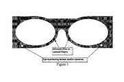
- FIG. 8A diagram of an embodiment of an eye-view recorder is shown in FIG. 8 .
- An EVRhas two groups of cameras or lenses.
- the embodiment illustrated in FIG. 8shows an eyeglass frame having a left template (or left arm) coupled to a left eyeglass lens holder area, and a right template (or right arm) coupled to a right eyeglass lens holder area.
- the left eyeglass lens holder areais coupled to the right eyeglass lens holder area view an eyeglass bridge.
- Viewing Camerasrecord the outside world or a scene of interest. Tracking Cameras monitor the eyes of the user.
- FIG. 8A diagram of an embodiment of an eye-view recorder has two groups of cameras or lenses.
- the embodiment illustrated in FIG. 8shows an eyeglass frame having a left template (or left arm) coupled to a left eyeglass lens holder area, and a right template (or right arm) coupled to a right eyeglass lens holder area.
- the left eyeglass lens holder areais coupled to the right eyeglass lens holder area view
- a left camera moduleis disposed within or on the left eyeglass template proximate to the left eyeglass lens holder area and a right camera module is disposed within or on the right eyeglass template proximate to the right eyeglass lens holder area.
- a left tracking lensis disposed in or on the left eyeglass lens holder area proximate to the left camera module, and a right tracking lens is disposed in or on the left eyeglass lens holder area proximate to the right camera module.
- each pair of eyeglasseshas two arms, left and right or L and R, for short.
- One embodiment of the camerais shown in FIG. 8 as described above. Further embodiments of the eye-view recorder (EVR) are described below.
- identical lensesare disposed on each arm of the EVR.
- a 3D (stereo) video recorderis provided.
- a 1 ⁇ 4′′ lens with a typical field of view (FOV) of about 45 degreescan be placed on each arm.
- FOVfield of view
- This cameracan be turned into a 3D (three dimensional) video recorder.
- the two camerascould also be arranged for a small overlap to maximize the horizontal FOV.
- focus invariant camera chipssuch as that of OmniVision Technologies' TrueFocus camera chips in each arm. These modules are small in size and lightweight.
- a high quality videocan be captured with a singlet (a single lens) as opposed to compound lenses that are standard.
- a single lens imaging systemis described in U.S. Pat. No. 7,106,510 to Dowski, Jr which is incorporated herein by reference in its entirety.
- FIG. 10illustrates an embodiment in which dissimilar lenses are used on the each arm of the EVR.
- a large FOVsuch as a fisheye lens
- a typical lensabout 45 degrees
- a lens with smaller FOVis placed on the other arm.
- the cameracan capture two views of every scene, a high resolution but narrow FOV and a lower resolution but wider FOV (similar to human peripheral view.)
- the center portion of the wide FOV imagemay also be replaced with the high resolution image from the other camera.
- Various embodimentsmay implement such a technique and to apply it to video to compensate for the reduced size of the lens and/or the detector.
- a high-resolution shot of the wide FOV imageswill be generated and the resultant video stored for interactive display or showing Region Of Interest (ROI) from the eye tracking circuit.
- ROIRegion Of Interest
- the usercan steer the camera after the fact per his/her interest. This makes video watching interactive.
- High-resolution review on the flymay also be provided when the user wants to view a certain region of the low resolution image. This will allow use of less storage memory space which will be highly useful to storing data from security cameras.
- Feedback from eye tracking circuitrymay also be used to display where users' eyes are focusing.
- this techniqueallows following a user's eyes with a fixed lens and still create a high resolution image at every angle.
- a camera tilt and panare done through mechanical means but here we achieve the same objectives with two fixed camera modules and with the help of super-resolution techniques.
- the userhas the option to enhance the image with the electronic box that comes with the glasses or it can be done later on a PC or on a server. This extends battery life of the electronic box.
- FIG. 11 aan array of small lenses may be used, such as the camera modules with three imaging lenses as illustrated in FIGS. 11 b & 11 c , to cover a desired large field of view (FOV).
- FIG. 12illustrates an embodiment of a camera module with three imaging lenses and their corresponding FOVs. This allows the thickness (width) of each arm to be reduced at the expense of increasing the height of the viewing camera modules.
- Each smaller cameramay have its own detector or all the smaller lenses utilize different areas of the same but a larger detector such as illustrated in FIG. 13 .
- FIG. 13an embodiment is illustrated in which fused fiber tapers are utilized to couple lenses outputs into a common CMOS detector.
- the fused fiber tapers by Schottcan achieve 100 LP/mm of resolution.
- An advantage of using a single detectoris reducing the electronics in the eyeglasses arms.
- the same ADCAnalog to Digital Convertor
- the same image processing unit and reference clockcan be used as well as the same image processing unit and reference clock. Consequently, a reduction in power consumption may be achieved compared to the case of in which multiple detectors are used.
- an array of smaller lensesmay be used instead of a typical lens.
- one implementationreplaces a typical 1 ⁇ 4′′ lens with three 1 ⁇ 6′′ or 1 ⁇ 8′′ lenses. Again the three lenses could share the same detector or have their own independent detectors. However, in this implementation, all three lenses must point in the same direction.
- the three lenseshave a single color filter per module. In this case, one camera sees only the green color, the other blue and the last one red. It is possible to use two lenses instead of three. In this case, the first camera will have a green filter and the second camera with have a color filter array with alternating red and blue filters. Because the human eye is more sensitive to the green color, one module for green color may used but red and blue colors may share another camera.
- An advantage of using three modules with three different color filtersis to eliminate computation in the image pipe to estimate the missing colors, and to eliminate numerical artifacts that results due to such computations.
- small camera chipssuch 1/10′′, 1/13′′ or 1/18′′ are embedded in the frame for eye tracking purposes. With such tracking cameras in place, the EVR will know where the user is looking. This information may be used to generate one version of the recorded video to be only what the user looked at as monitored by the eye tracking circuit.
- One or two tiny camerasmay be used to monitor the gaze direction.
- very low power infrared LEDsmay be placed to illuminate the eye surface.
- the detectormay include an IR filter to block all the other unwanted lights.
- infraredis eye-safe. Since it is only necessary to illuminate the eye surface from a very close distance, lower doses of IR power may be used.
- Still another embodimentis based on utilizing the eye-tracking circuit discussed above.
- human eye visionhas two regions: high sensitive area (fovea vision) that is used to concentrate and read with and the rest which is called peripheral view. Text cannot be read in the peripheral view.
- this featureis duplicated with the eye-view recorder (EVR).
- EMReye-view recorder
- a high-resolution sensorfor example, a four-mega pixel detector, reads all the pixels.
- the input from the eye-tracking circuitis used to determine the gaze direction, which is most of the time in the head direction.
- the scene distance from the useris also determined from the stereo images that are collected through two different cameras.
- the angular range of human focusis also known and the distance information is used to decide what portion is to be shown with high resolution. This is displayed as a square area (all screens that are used are rectangular), which is the closet to a circle that can be seen.
- the focus areacan also be shown as a circle, but then this circle is enclosed within a 4 ⁇ 3 or 16 ⁇ 9 rectangle to show only the region of interest.
- Another optionis to show the focused area within the recorded peripheral view.
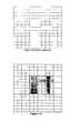
- the usercan choose to show the peripheral as human like or with high resolution. For human like display, the resolution of the peripherals needs to be lowered. This is done two ways. First, A group of pixels is binned and their outputs are read as only one pixel. Second, low pass filtering is used once all data is collected or just prior to display.
- FIG. 14shows binning on the high resolution detector: all pixels shown (top), Region Of Interest (ROI) shown in gray has 4 times more resolution than the peripherals (bottom).
- a matched filtering techniquesuch as Weiner—See Fourier Optics by Joseph Goodman
- super-resolution techniquesare used to enhance the images and increase their resolution. Super-resolution allows optical zooming to be performed without any moving parts in the camera.
- the point spread function of a lensis location dependent. Prior to using a lens, its PSF as function of x, y and z is measured and recorded. From two- or multi-camera arrangements, the location of each object point with respect to the cameras can be accurately determined. Knowing the transfer function of the lens and the detector array, the bandwidth limiting effects (lowered resolution) of these components can be compensated for thereby improving the image quality. In various embodiments, such computations are performed off-line to save battery power.
- the cameramay use wireless links to offload its image data to a server. The server performs the processing and makes it available to the user for subsequent viewing. It is also possible that the user downloads the images to a PC and uses software that is provided to undo the effects of the lenses and provide image enhancement.
- Focus invariant camerasintentionally blur images at the image plane but through electronic processing provide crisp pictures.
- such camerasare used.
- the battery lifecan be extended and second, the blurred images are hardly of much value or attention.
- the recorded datamay be encrypted.
- the camera unitis provided with a software key that is stored on user's personal computers or on the server. No one else will be able to access the recorded information.
- An advantage of this featureis to provide privacy and security for what was viewed.
- Embodiments of the EVRprovide optical zoom, pan and tilt without any moving parts. These are referred to as “soft zoom”, “soft tilt” and “soft pan.”
- a fisheye lensis used to record a FOV similar to a human eye.
- a second lens that has a narrow FOVis used and the images from this camera are used to enhance the images recorded by the fisheye lens using super-resolution techniques such as described by Joseph Goodman cited above and by Anil Bharath and Maria Petrou, “Next Generation Artificial Vision Systems,” Artech House 2008, ISBN 1-59693-224-4, Chapters 5, 6 and 7.
- Increasing the resolution of the fisheye images by a factor of fouris the same as achieving 4 ⁇ optical resolution but without losing the FOV by the same factor. Given this, users are allowed to interactively look at different part of the scene or make the eye viewed frames available to them anywhere within the extended FOV. This is equivalent to pan and tilt and are performed with no mechanical movements.
- the focus of the eyeschanges to follow the object automatically.
- the super-resolution imagescan be used to adjust the frame size properly to capture a dynamic and human like image or video. This results in a dynamic magnification as opposed to a fixed value provided by a lens of typical low cost point-and-shoot cameras.
- RGBRed Green Blue
- RGB Bayer patternwhich is suitable for “high light” environments. At least one embodiments uses this pattern on one side.
- a two camera configuration for High Dynamic Range (HDR) imagingis used.
- one camerais used as the main camera and the other as the auxiliary.
- the auxiliary cameratakes several pictures at shutter speeds different from the main camera. These additional pictures are used to enhance the main image (in case of taking still images) or the main frame (in the case of recording video).
- the images from the auxiliary cameraare used to adjust the dynamic range in each portion of the main image.
- the auxiliary cameradoes not need to have the same resolution because the intention is to equalize the image or the frame properly.
- a lower resolution cameracan be operated at higher speeds which is what we need to enhance the main picture.
- One use of the eye-view recorderis to take daily snapshots of what a user does.
- the picturesmay be taken every predetermined number of seconds or minutes but the detail is sharp with this scheme.
- Standard HDR imagingis defined as taking multiple shuts from the same scene at different shutter speeds. However, this is not always possible because the subject may move or the camera might be moved. In at least one embodiment, a separate camera that can simultaneously capture images is used to address this problem.
- CFAin front detectors requires computations to estimate 2 other color values for each measured pixel. This often results in numerical artifacts for certain patterns.
- three identical camerasare placed vertically on top of each other instead of a single camera.
- the lens for the three camerasis smaller than in the single camera case but two goals are achieved: using smaller lenses placed vertically is less distractive than a single larger lens.
- Each smaller camerahas only one single filter.
- the lightis split among three colors after it passes through the lens. The focus of this embodiment is to reduce the size of the lens as much as possible to make the frame look normal. Instead of one large lens, three smaller lenses are used to collect the same amount of light per pixel.
- Standard single lens camcorderssuch as Flip by Pure Digital Technology have a viewing range from one meter to infinity. However, human eyes see distances from 25 cm and farther. By using focus-invariant lenses in at least one embodiment, human like zoom range is achieved with reasonably small lens size to acquire good pictures.
- an accelerometeris placed on the camera (eyeglasses frame in this case) to detect movements of the camera due to head movements. Detectors that can operate at high frame rates, 250 fps and more, are used. The frame rate (shutter speed) is increased linearly by the head rotation or movement. This allows recording of sharp video frames and provides a smooth and human like transition as video cameras move. Software may be used to convert fixed frame rates to higher rates so that blurring due to video transition is eliminated or minimized. We may also use the movement vector to remove the blur from the image frames using digital signal processing de-blurring techniques.
- IR or night visionHuman eyes can not see well in the dark but there are cameras (IR or night vision) that can be used for imaging at dark.
- a two-mode camerais used to enable recording at day and night.
- One camerais normal and it records at day light, and the other camera has infra-red detectors.
- Infra-red detectorsare of many types.
- existing CMOS detectorsare used in conjunction with an optical filter that allows only the IR light to get in and blocks white light (blue, green and red).
- Other IR detectorshave much better quantum efficiencies at IR than CMOS detectors. By using such detectors, better night images are obtained.
- one side of the camerahas day vision and another has night vision.
- a single night vision camerais provided for the whole array to provide extra capabilities for the eye-view recorder.
- the optical lensescan separate the optical lenses from the imaging detector by employing a length of fiber imaging devices such as those manufactured by Schott. Such fiber currently can achieve a resolution of 50 LP/mm. An advantage of using this scheme is to consume much less or no electrical power in the frame area.
- the eyeglassesare made totally passive by using such imaging fibers to monitor the user's eye for eye tracking purposes. At the electronic box or later during signal processing, de-convolving the effect of the imaging fibers is performed before producing the final images. Such a resolution is sufficient for VGA and HD video.
- Using an imaging fiber to couple the light from a lens to a detectoris applicable to various embodiments. In effect, every claim and configuration above can be restated when imaging fiber is used between the lens and the detector. Just like lenses, imaging fibers have different numerical apertures (NA). Higher NA fibers can be used with larger FOV lenses.
- FIG. 15illustrates an embodiment of the EVR showing two lenses on the right and left sides of the frame, their associated FOV, and display of left FOV in the orthogonal plane (a circular pattern).
- FIG. 16illustrates an embodiment of the EVR in which one camera takes a wide FOV image and the camera on the other side provide spatial sampling of the wide FOV through a narrower FOV camera.
- multi-camerasare used to sample various portions of the wider FOV.
- An exampleis shown in FIG. 16 in which five high resolution and narrow FOV are used to spatially sample the wide FOV.
- the previous embodimentprovides a configuration to achieve geometrical optical super-resolution to enhance the recorded images by each camera. It is desired to try to minimize the used space within the camera frame to make it as normal looking as possible. There are large commercially available CMOS and CCD detectors but there is not enough space to accommodate such pieces in the frame. As a result, Optical Super-Resolution (OSR) techniques are resorted to. To achieve a geometrical resolution N times smaller than resolution achieved by the detector pixel size, OSR techniques such as described in Zeev Zalevsky, David Mendlovic, “Optical Superresolution,” Springer 2004, ISBN 0387-00591-9 are used.
- a standard 1 ⁇ 4inch detectoris used in many commercial cameras. These have a typical FOV of 45 degrees. In various embodiments, it is desired to extend this FOV by a factor of 2 to 5. With no compensation, extending FOV for the same detector results in lowering the image resolution. Human FOV is about 200 degrees.
- the imageis moved across the detector 4 times per frame in steps of a quarter (1 ⁇ 4) of the pixel size of the detector array.
- FIG. 17A configuration to achieve this type of OSR is shown in FIG. 17 .
- FIG. 17an embodiment is illustrated in which a microelectromechanical systems (MEMS) mirror is utilized to steer the beam across the detector surface in two dimensions. The image is two dimensional, hence steering in two orthogonal directions is needed.
- MEMSmicroelectromechanical systems
- An embodiment of another OSR implementationis to place a diffractive optical element (such as a wire mesh) right after the lens and in between the lens and the detector.
- a diffractive optical elementsuch as a wire mesh
- This configurationachieves high resolution at the expense of reducing FOV. For example, a 4 ⁇ improvement in resolution requires a 4 ⁇ reduction in the FOV viewed by the lens. It is possible to select various diffraction orders to zoom into different portions of the FOV or to send each diffraction order to a different detector for OSR.
- optical fibersare used to send the signal outputs down to the electronic box.
- the transmitter sourceis an LED (Light Emitting Diode) or a VCSEL (Vertically Coupled Surface Emitting Laser).
- LEDLight Emitting Diode
- VCSELVery Coupled Surface Emitting Laser
- Such componentsare extremely small in size, consume low power and have very high reliability rates.
- a drivermay be integrated with the source to further reduce the space and power consumption.
- a metal coated fibermay be used for electrical power deliver to the frame.
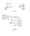
- FIG. 18A schematic diagram of such an embodiment shown in FIG. 18 in which camera outputs are transmitted from the eyeglasses frame to the electronic box via a fiber.
- Camera-1 to Camera-Nsend signals to a multiplexer.
- the multiplexerprovides the multiplexed signal to a VCSEL which is coupled to a detector via a fiber.
- the VCSELsends the multiplexed signal to the detector over the fiber, and the detector provides the multiplexed signal to a demultiplexer.
- the demultiplexed signalsare provided as Image-1 to Image-N.
- camera modulesthere are at least two kinds of camera modules that can be used. Some already have serial output data and others provide parallel data output. Using parallel output data requires more wires to connect the send the data to the electronic box.
- One optionis to use a serializer per camera module.
- Some camera modulessuch as those made by Aptina (Micron) have serial outputs. Furthermore, these modules can accept a serial output from another camera module and interleave the output of the two modules in one serial stream. In various embodiments, such camera modules may be used to interleave (multiplex) the output of the outside looking camera and an eye tracking camera.
- additional camerasare placed on the side of the temples to achieve a total FOV around 270 degrees which is much larger than what human eyes can achieve. These additional cameras are always looking sideways. This is useful for virtual reality applications or interactive revisit of a scene or an experience.
Landscapes
- Engineering & Computer Science (AREA)
- Physics & Mathematics (AREA)
- Theoretical Computer Science (AREA)
- General Engineering & Computer Science (AREA)
- Multimedia (AREA)
- Signal Processing (AREA)
- General Physics & Mathematics (AREA)
- Human Computer Interaction (AREA)
- Computer Hardware Design (AREA)
- Health & Medical Sciences (AREA)
- Acoustics & Sound (AREA)
- General Health & Medical Sciences (AREA)
- Otolaryngology (AREA)
- Ophthalmology & Optometry (AREA)
- Optics & Photonics (AREA)
- Studio Devices (AREA)
Abstract
Description
Claims (1)
Priority Applications (25)
| Application Number | Priority Date | Filing Date | Title |
|---|---|---|---|
| US12/794,283US8872910B1 (en) | 2009-06-04 | 2010-06-04 | Method and apparatus for a compact and high resolution eye-view recorder |
| US14/523,386US9894326B2 (en) | 2009-06-04 | 2014-10-24 | Method and apparatus for an attention monitoring eye-view recorder |
| US14/985,398US9727790B1 (en) | 2010-06-04 | 2015-12-31 | Method and apparatus for a wearable computer with natural user interface |
| US15/400,399US10064552B1 (en) | 2009-06-04 | 2017-01-06 | Method and apparatus for a compact and high resolution mind-view communicator |
| US15/663,753US10019634B2 (en) | 2010-06-04 | 2017-07-30 | Method and apparatus for an eye tracking wearable computer |
| US15/859,333US10623705B2 (en) | 2009-06-04 | 2017-12-30 | Method and apparatus for a wearable imaging device |
| US15/859,525US10354146B1 (en) | 2009-06-04 | 2017-12-31 | Method and apparatus for an eye tracking wearable computer |
| US15/859,526US10423837B2 (en) | 2009-06-04 | 2017-12-31 | Method and apparatus for a wearable computer |
| US15/893,724US10687027B1 (en) | 2009-06-04 | 2018-02-12 | Method and apparatus for a wearable imaging device |
| US16/055,130US10674912B1 (en) | 2009-06-04 | 2018-08-05 | Method and apparatus for a compact and high resolution mind-view communicator |
| US16/120,326US10687708B1 (en) | 2009-06-04 | 2018-09-03 | Method and apparatus for a compact and high resolution mind-view communicator |
| US16/578,285US11450113B1 (en) | 2009-06-04 | 2019-09-21 | Method and apparatus for a wearable computer |
| US16/687,675US11367164B1 (en) | 2009-06-04 | 2019-11-18 | Method and apparatus for super resolution imaging and eye tracking devices |
| US16/901,761US11716449B1 (en) | 2009-06-04 | 2020-06-15 | Method and apparatus for an imaging device |
| US16/908,514US11432723B1 (en) | 2009-06-04 | 2020-06-22 | Method and apparatus for a compact and high resolution mind-view communicator |
| US17/887,438US11937895B1 (en) | 2009-06-04 | 2022-08-13 | Method and apparatus for a compact and high resolution mind-view communicator |
| US18/363,726US20240121364A1 (en) | 2009-06-04 | 2023-08-01 | Method and apparatus for an imaging device |
| US18/431,800US12336782B2 (en) | 2009-06-04 | 2024-02-02 | Method and apparatus for a compact and high resolution mind-view communicator |
| US18/746,575US12340590B2 (en) | 2009-06-04 | 2024-06-18 | Method and apparatus for a wearable computer |
| US19/010,350US12376747B2 (en) | 2009-06-04 | 2025-01-06 | Method and apparatus for a compact and high resolution mind-view communicator |
| US19/010,438US20250142024A1 (en) | 2009-06-04 | 2025-01-06 | Method and apparatus for an imaging device |
| US19/010,448US20250142025A1 (en) | 2009-06-04 | 2025-01-06 | Method and apparatus for an imaging device |
| US19/010,363US12303228B2 (en) | 2009-06-04 | 2025-01-06 | Method and apparatus for a compact and high resolution mind-view communicator |
| US19/198,503US20250261858A1 (en) | 2009-06-04 | 2025-05-05 | Method and apparatus for a compact and high resolution mind-view communicator |
| US19/239,365US20250316089A1 (en) | 2009-06-04 | 2025-06-16 | Method and apparatus for a wearable computer |
Applications Claiming Priority (2)
| Application Number | Priority Date | Filing Date | Title |
|---|---|---|---|
| US18423209P | 2009-06-04 | 2009-06-04 | |
| US12/794,283US8872910B1 (en) | 2009-06-04 | 2010-06-04 | Method and apparatus for a compact and high resolution eye-view recorder |
Related Parent Applications (1)
| Application Number | Title | Priority Date | Filing Date |
|---|---|---|---|
| US14/523,386Continuation-In-PartUS9894326B2 (en) | 2009-06-04 | 2014-10-24 | Method and apparatus for an attention monitoring eye-view recorder |
Related Child Applications (3)
| Application Number | Title | Priority Date | Filing Date |
|---|---|---|---|
| US201113175421AContinuation-In-Part | 2009-06-04 | 2011-07-01 | |
| US14/523,386ContinuationUS9894326B2 (en) | 2009-06-04 | 2014-10-24 | Method and apparatus for an attention monitoring eye-view recorder |
| US15/400,399Continuation-In-PartUS10064552B1 (en) | 2009-06-04 | 2017-01-06 | Method and apparatus for a compact and high resolution mind-view communicator |
Publications (1)
| Publication Number | Publication Date |
|---|---|
| US8872910B1true US8872910B1 (en) | 2014-10-28 |
Family
ID=51752748
Family Applications (8)
| Application Number | Title | Priority Date | Filing Date |
|---|---|---|---|
| US12/794,283Active2031-03-05US8872910B1 (en) | 2009-06-04 | 2010-06-04 | Method and apparatus for a compact and high resolution eye-view recorder |
| US14/523,386Active2031-12-23US9894326B2 (en) | 2009-06-04 | 2014-10-24 | Method and apparatus for an attention monitoring eye-view recorder |
| US15/859,333Active2030-08-27US10623705B2 (en) | 2009-06-04 | 2017-12-30 | Method and apparatus for a wearable imaging device |
| US15/893,724Active2030-10-22US10687027B1 (en) | 2009-06-04 | 2018-02-12 | Method and apparatus for a wearable imaging device |
| US16/901,761ActiveUS11716449B1 (en) | 2009-06-04 | 2020-06-15 | Method and apparatus for an imaging device |
| US18/363,726PendingUS20240121364A1 (en) | 2009-06-04 | 2023-08-01 | Method and apparatus for an imaging device |
| US19/010,438PendingUS20250142024A1 (en) | 2009-06-04 | 2025-01-06 | Method and apparatus for an imaging device |
| US19/010,448PendingUS20250142025A1 (en) | 2009-06-04 | 2025-01-06 | Method and apparatus for an imaging device |
Family Applications After (7)
| Application Number | Title | Priority Date | Filing Date |
|---|---|---|---|
| US14/523,386Active2031-12-23US9894326B2 (en) | 2009-06-04 | 2014-10-24 | Method and apparatus for an attention monitoring eye-view recorder |
| US15/859,333Active2030-08-27US10623705B2 (en) | 2009-06-04 | 2017-12-30 | Method and apparatus for a wearable imaging device |
| US15/893,724Active2030-10-22US10687027B1 (en) | 2009-06-04 | 2018-02-12 | Method and apparatus for a wearable imaging device |
| US16/901,761ActiveUS11716449B1 (en) | 2009-06-04 | 2020-06-15 | Method and apparatus for an imaging device |
| US18/363,726PendingUS20240121364A1 (en) | 2009-06-04 | 2023-08-01 | Method and apparatus for an imaging device |
| US19/010,438PendingUS20250142024A1 (en) | 2009-06-04 | 2025-01-06 | Method and apparatus for an imaging device |
| US19/010,448PendingUS20250142025A1 (en) | 2009-06-04 | 2025-01-06 | Method and apparatus for an imaging device |
Country Status (1)
| Country | Link |
|---|---|
| US (8) | US8872910B1 (en) |
Cited By (26)
| Publication number | Priority date | Publication date | Assignee | Title |
|---|---|---|---|---|
| US20130083197A1 (en)* | 2010-05-25 | 2013-04-04 | Fujitsu Limited | Storage managing method and storage management device |
| US20140184801A1 (en)* | 2013-01-02 | 2014-07-03 | Samsung Electronics Co., Ltd. | Wearable video device and video system including the same |
| US20150138319A1 (en)* | 2011-08-25 | 2015-05-21 | Panasonic Intellectual Property Corporation Of America | Image processor, 3d image capture device, image processing method, and image processing program |
| US20150208244A1 (en)* | 2012-09-27 | 2015-07-23 | Kyocera Corporation | Terminal device |
| US9720089B2 (en)* | 2012-01-23 | 2017-08-01 | Microsoft Technology Licensing, Llc | 3D zoom imager |
| US9857919B2 (en)* | 2012-05-17 | 2018-01-02 | Hong Kong Applied Science And Technology Research | Wearable device with intelligent user-input interface |
| EP3332284A1 (en)* | 2015-08-07 | 2018-06-13 | SensoMotoric Instruments Gesellschaft für innovative Sensorik mbH | Method and apparatus for data capture and evaluation of ambient data |
| US20180184138A1 (en)* | 2015-06-15 | 2018-06-28 | Piksel, Inc. | Synchronisation of streamed content |
| US20180220068A1 (en)* | 2017-01-31 | 2018-08-02 | Microsoft Technology Licensing, Llc | Foveated camera for video augmented reality and head mounted display |
| US20190108735A1 (en)* | 2017-10-10 | 2019-04-11 | Weixin Xu | Globally optimized recognition system and service design, from sensing to recognition |
| US10354140B2 (en) | 2017-01-31 | 2019-07-16 | Microsoft Technology Licensing, Llc | Video noise reduction for video augmented reality system |
| US10397546B2 (en) | 2015-09-30 | 2019-08-27 | Microsoft Technology Licensing, Llc | Range imaging |
| US10462452B2 (en) | 2016-03-16 | 2019-10-29 | Microsoft Technology Licensing, Llc | Synchronizing active illumination cameras |
| US10504397B2 (en) | 2017-01-31 | 2019-12-10 | Microsoft Technology Licensing, Llc | Curved narrowband illuminant display for head mounted display |
| US10523923B2 (en) | 2015-12-28 | 2019-12-31 | Microsoft Technology Licensing, Llc | Synchronizing active illumination cameras |
| CN111553283A (en)* | 2020-04-29 | 2020-08-18 | 北京百度网讯科技有限公司 | Method and device for generating model |
| US20210038140A1 (en)* | 2018-03-13 | 2021-02-11 | Kaneka Corporation | Assessment system and assessment method |
| US11187909B2 (en) | 2017-01-31 | 2021-11-30 | Microsoft Technology Licensing, Llc | Text rendering by microshifting the display in a head mounted display |
| US11367164B1 (en) | 2009-06-04 | 2022-06-21 | Masoud Vaziri | Method and apparatus for super resolution imaging and eye tracking devices |
| US11432723B1 (en)* | 2009-06-04 | 2022-09-06 | Masoud Vaziri | Method and apparatus for a compact and high resolution mind-view communicator |
| US11450113B1 (en) | 2009-06-04 | 2022-09-20 | Masoud Vaziri | Method and apparatus for a wearable computer |
| US11716449B1 (en) | 2009-06-04 | 2023-08-01 | Mojtaba Vaziri | Method and apparatus for an imaging device |
| US11800244B1 (en) | 2022-08-13 | 2023-10-24 | Mojtaba Vaziri | Method and apparatus for an imaging device |
| LU503212B1 (en)* | 2022-12-19 | 2024-06-19 | Arspectra S A R L | Head mounted display device and system |
| US12229922B1 (en) | 2018-07-11 | 2025-02-18 | Optics Innovation Llc | Method and apparatus for a software enabled high resolution ultrasound imaging device |
| USRE50624E1 (en) | 2018-11-19 | 2025-10-07 | Optics Innovation Llc | Method and apparatus for super resolution imaging and eye tracking devices |
Families Citing this family (28)
| Publication number | Priority date | Publication date | Assignee | Title |
|---|---|---|---|---|
| KR102483838B1 (en)* | 2015-04-19 | 2023-01-02 | 포토내이션 리미티드 | Multi-Baseline Camera Array System Architecture for Depth Augmentation in VR/AR Applications |
| EP3280154B1 (en)* | 2016-08-04 | 2019-10-02 | Harman Becker Automotive Systems GmbH | System and method for operating a wearable loudspeaker device |
| US10330935B2 (en)* | 2016-09-22 | 2019-06-25 | Apple Inc. | Predictive, foveated virtual reality system |
| US10623634B2 (en)* | 2017-04-17 | 2020-04-14 | Intel Corporation | Systems and methods for 360 video capture and display based on eye tracking including gaze based warnings and eye accommodation matching |
| CN109151397A (en)* | 2018-10-19 | 2019-01-04 | 天津英田视讯科技有限公司 | A kind of control and monitoring system for ships based on panorama ball and laser night-vision device |
| CN111291585B (en)* | 2018-12-06 | 2023-12-08 | 杭州海康威视数字技术股份有限公司 | GPS-based target tracking system, method and device and ball machine |
| EP3991013A1 (en) | 2019-06-28 | 2022-05-04 | Sony Group Corporation | Method, computer program and head-mounted device for triggering an action, method and computer program for a computing device and computing device |
| US11270110B2 (en) | 2019-09-17 | 2022-03-08 | Boston Polarimetrics, Inc. | Systems and methods for surface modeling using polarization cues |
| WO2021071992A1 (en) | 2019-10-07 | 2021-04-15 | Boston Polarimetrics, Inc. | Systems and methods for augmentation of sensor systems and imaging systems with polarization |
| DE112020005932T5 (en) | 2019-11-30 | 2023-01-05 | Boston Polarimetrics, Inc. | SYSTEMS AND METHODS FOR SEGMENTATION OF TRANSPARENT OBJECTS USING POLARIZATION CHARACTERISTICS |
| EP4081933A4 (en) | 2020-01-29 | 2024-03-20 | Intrinsic Innovation LLC | Systems and methods for characterizing object pose detection and measurement systems |
| US11797863B2 (en) | 2020-01-30 | 2023-10-24 | Intrinsic Innovation Llc | Systems and methods for synthesizing data for training statistical models on different imaging modalities including polarized images |
| US11953700B2 (en) | 2020-05-27 | 2024-04-09 | Intrinsic Innovation Llc | Multi-aperture polarization optical systems using beam splitters |
| US12015842B2 (en)* | 2020-09-30 | 2024-06-18 | Snap Inc. | Multi-purpose cameras for simultaneous capture and CV on wearable AR devices |
| US12267585B2 (en) | 2020-09-30 | 2025-04-01 | Snap Inc. | Ultra low power camera pipeline for CV in AR systems |
| US11622100B2 (en)* | 2021-02-17 | 2023-04-04 | flexxCOACH VR | 360-degree virtual-reality system for dynamic events |
| US12020455B2 (en) | 2021-03-10 | 2024-06-25 | Intrinsic Innovation Llc | Systems and methods for high dynamic range image reconstruction |
| US12069227B2 (en) | 2021-03-10 | 2024-08-20 | Intrinsic Innovation Llc | Multi-modal and multi-spectral stereo camera arrays |
| US11290658B1 (en) | 2021-04-15 | 2022-03-29 | Boston Polarimetrics, Inc. | Systems and methods for camera exposure control |
| US11954886B2 (en) | 2021-04-15 | 2024-04-09 | Intrinsic Innovation Llc | Systems and methods for six-degree of freedom pose estimation of deformable objects |
| US12067746B2 (en) | 2021-05-07 | 2024-08-20 | Intrinsic Innovation Llc | Systems and methods for using computer vision to pick up small objects |
| US12175741B2 (en) | 2021-06-22 | 2024-12-24 | Intrinsic Innovation Llc | Systems and methods for a vision guided end effector |
| US12340538B2 (en) | 2021-06-25 | 2025-06-24 | Intrinsic Innovation Llc | Systems and methods for generating and using visual datasets for training computer vision models |
| US12172310B2 (en) | 2021-06-29 | 2024-12-24 | Intrinsic Innovation Llc | Systems and methods for picking objects using 3-D geometry and segmentation |
| US11689813B2 (en) | 2021-07-01 | 2023-06-27 | Intrinsic Innovation Llc | Systems and methods for high dynamic range imaging using crossed polarizers |
| US12293535B2 (en) | 2021-08-03 | 2025-05-06 | Intrinsic Innovation Llc | Systems and methods for training pose estimators in computer vision |
| US11490034B1 (en) | 2021-11-29 | 2022-11-01 | Unity Technologies Sf | Increasing resolution and luminance of a display |
| US20240244337A1 (en)* | 2023-01-13 | 2024-07-18 | Clarity.GolfInc. | Data collection by a dynamic area of interest camera technique |
Citations (7)
| Publication number | Priority date | Publication date | Assignee | Title |
|---|---|---|---|---|
| US6198485B1 (en)* | 1998-07-29 | 2001-03-06 | Intel Corporation | Method and apparatus for three-dimensional input entry |
| US6307526B1 (en)* | 1998-02-02 | 2001-10-23 | W. Steve G. Mann | Wearable camera system with viewfinder means |
| US7331671B2 (en)* | 2004-03-29 | 2008-02-19 | Delphi Technologies, Inc. | Eye tracking method based on correlation and detected eye movement |
| US20100053555A1 (en)* | 2008-08-27 | 2010-03-04 | Locarna Systems, Inc. | Method and apparatus for tracking eye movement |
| US20100240988A1 (en)* | 2009-03-19 | 2010-09-23 | Kenneth Varga | Computer-aided system for 360 degree heads up display of safety/mission critical data |
| US20110279666A1 (en)* | 2009-01-26 | 2011-11-17 | Stroembom Johan | Detection of gaze point assisted by optical reference signal |
| US8139089B2 (en)* | 2003-11-17 | 2012-03-20 | Noregin Assets, N.V., L.L.C. | Navigating digital images using detail-in-context lenses |
Family Cites Families (60)
| Publication number | Priority date | Publication date | Assignee | Title |
|---|---|---|---|---|
| US4028725A (en)* | 1976-04-21 | 1977-06-07 | Grumman Aerospace Corporation | High-resolution vision system |
| US5262871A (en) | 1989-11-13 | 1993-11-16 | Rutgers, The State University | Multiple resolution image sensor |
| US20060033992A1 (en)* | 2002-12-02 | 2006-02-16 | Solomon Dennis J | Advanced integrated scanning focal immersive visual display |
| AUPN003894A0 (en)* | 1994-12-13 | 1995-01-12 | Xenotech Research Pty Ltd | Head tracking system for stereoscopic display apparatus |
| JP3452685B2 (en) | 1995-05-10 | 2003-09-29 | 三菱電機株式会社 | Face image processing device |
| CA2307877C (en)* | 1997-10-30 | 2005-08-30 | The Microoptical Corporation | Eyeglass interface system |
| US6434280B1 (en)* | 1997-11-10 | 2002-08-13 | Gentech Corporation | System and method for generating super-resolution-enhanced mosaic images |
| WO2000007066A1 (en)* | 1998-07-29 | 2000-02-10 | Digilens, Inc. | In-line infinity display system employing one or more switchable holographic optical elements |
| WO2001006476A2 (en) | 1999-07-19 | 2001-01-25 | The University Of West Florida | A computer based human-centered display system |
| JP2001169257A (en) | 1999-12-14 | 2001-06-22 | Matsushita Electric Ind Co Ltd | Video phone |
| US8431881B2 (en) | 2000-09-15 | 2013-04-30 | Kollsman, Inc. | Night vision goggles with pellicle |
| KR100391442B1 (en) | 2000-12-27 | 2003-07-12 | 현대자동차주식회사 | Image processing method for preventing a vehicle from running off the line |
| US6766067B2 (en)* | 2001-04-20 | 2004-07-20 | Mitsubishi Electric Research Laboratories, Inc. | One-pass super-resolution images |
| US6940645B2 (en)* | 2003-04-22 | 2005-09-06 | Eastman Kodak Company | Monocentric autostereoscopic optical apparatus with a spherical gradient-index ball lens |
| US7218796B2 (en)* | 2003-04-30 | 2007-05-15 | Microsoft Corporation | Patch-based video super-resolution |
| US20050046698A1 (en)* | 2003-09-02 | 2005-03-03 | Knight Andrew Frederick | System and method for producing a selectable view of an object space |
| US10039445B1 (en)* | 2004-04-01 | 2018-08-07 | Google Llc | Biosensors, communicators, and controllers monitoring eye movement and methods for using them |
| WO2006011635A1 (en) | 2004-07-30 | 2006-02-02 | Canon Kabushiki Kaisha | Image processing method and apparatus, image sensing apparatus, and program |
| KR100693412B1 (en) | 2005-05-16 | 2007-03-09 | 주식회사 아이디테크 | How to detect eye of surveillance object in image |
| US7715658B2 (en)* | 2005-08-03 | 2010-05-11 | Samsung Electronics Co., Ltd. | Apparatus and method for super-resolution enhancement processing |
| US7697024B2 (en)* | 2005-11-03 | 2010-04-13 | Broadcom Corp. | Method and system of tracking and stabilizing an image transmitted using video telephony |
| JP4175390B2 (en)* | 2006-06-09 | 2008-11-05 | ソニー株式会社 | Information processing apparatus, information processing method, and computer program |
| US8189100B2 (en)* | 2006-07-25 | 2012-05-29 | Qualcomm Incorporated | Mobile device with dual digital camera sensors and methods of using the same |
| US20080030592A1 (en)* | 2006-08-01 | 2008-02-07 | Eastman Kodak Company | Producing digital image with different resolution portions |
| US8446509B2 (en)* | 2006-08-09 | 2013-05-21 | Tenebraex Corporation | Methods of creating a virtual window |
| US8121356B2 (en)* | 2006-09-15 | 2012-02-21 | Identix Incorporated | Long distance multimodal biometric system and method |
| JP4818053B2 (en)* | 2006-10-10 | 2011-11-16 | 株式会社東芝 | High resolution device and method |
| US7484847B2 (en)* | 2007-01-02 | 2009-02-03 | Hind-Sight Industries, Inc. | Eyeglasses having integrated telescoping video camera and video display |
| US8154583B2 (en)* | 2007-05-31 | 2012-04-10 | Eastman Kodak Company | Eye gazing imaging for video communications |
| US8159519B2 (en)* | 2007-05-31 | 2012-04-17 | Eastman Kodak Company | Personal controls for personal video communications |
| JP5300433B2 (en)* | 2007-11-22 | 2013-09-25 | 株式会社半導体エネルギー研究所 | Image processing method and display device |
| JP4413261B2 (en)* | 2008-01-10 | 2010-02-10 | シャープ株式会社 | Imaging apparatus and optical axis control method |
| US8786675B2 (en)* | 2008-01-23 | 2014-07-22 | Michael F. Deering | Systems using eye mounted displays |
| US8824833B2 (en)* | 2008-02-01 | 2014-09-02 | Omnivision Technologies, Inc. | Image data fusion systems and methods |
| US20090219224A1 (en)* | 2008-02-28 | 2009-09-03 | Johannes Elg | Head tracking for enhanced 3d experience using face detection |
| US8432492B2 (en) | 2008-03-20 | 2013-04-30 | Institut Fuer Rundfunktechnik Gmbh | Method of adapting video images to small screen sizes |
| US20100149073A1 (en)* | 2008-11-02 | 2010-06-17 | David Chaum | Near to Eye Display System and Appliance |
| US8305899B2 (en) | 2008-05-28 | 2012-11-06 | Microsoft Corporation | Pull-based data transmission approach |
| US8842190B2 (en)* | 2008-08-29 | 2014-09-23 | Adobe Systems Incorporated | Method and apparatus for determining sensor format factors from image metadata |
| US20100103276A1 (en)* | 2008-10-28 | 2010-04-29 | Border John N | Split aperture capture of rangemap for 3d imaging |
| US20100157079A1 (en)* | 2008-12-19 | 2010-06-24 | Qualcomm Incorporated | System and method to selectively combine images |
| US8339475B2 (en)* | 2008-12-19 | 2012-12-25 | Qualcomm Incorporated | High dynamic range image combining |
| US7997723B2 (en)* | 2008-12-31 | 2011-08-16 | Nokia Corporation | Display apparatus and device |
| US7819525B2 (en)* | 2009-02-15 | 2010-10-26 | International Business Machines Corporation | Automatic direct gaze detection based on pupil symmetry |
| US8233747B2 (en)* | 2009-04-03 | 2012-07-31 | Sony Corporation | Method and apparatus for forming super resolution images from raw data representative of color filter array images |
| US8553106B2 (en)* | 2009-05-04 | 2013-10-08 | Digitaloptics Corporation | Dual lens digital zoom |
| US8872910B1 (en) | 2009-06-04 | 2014-10-28 | Masoud Vaziri | Method and apparatus for a compact and high resolution eye-view recorder |
| US10064552B1 (en) | 2009-06-04 | 2018-09-04 | Masoud Vaziri | Method and apparatus for a compact and high resolution mind-view communicator |
| US9727790B1 (en) | 2010-06-04 | 2017-08-08 | Masoud Vaziri | Method and apparatus for a wearable computer with natural user interface |
| US20110263946A1 (en)* | 2010-04-22 | 2011-10-27 | Mit Media Lab | Method and system for real-time and offline analysis, inference, tagging of and responding to person(s) experiences |
| US9618746B2 (en) | 2010-11-19 | 2017-04-11 | SA Photonics, Inc. | High resolution wide field of view digital night vision system |
| KR101783982B1 (en) | 2012-01-31 | 2017-10-11 | 한화테크윈 주식회사 | Integration Control System and Method Using Surveillance Camera for Vehicle |
| US20130242057A1 (en)* | 2012-03-16 | 2013-09-19 | Research In Motion Limited | Methods and devices for producing an enhanced image |
| EP2642752A1 (en) | 2012-03-23 | 2013-09-25 | Alcatel Lucent | Method, server, and terminal for conducting a video conference |
| US9589181B2 (en)* | 2013-02-28 | 2017-03-07 | Hitachi Kokusai Electric Inc. | Person search method and device for searching person staying on platform |
| US9674490B2 (en) | 2013-04-18 | 2017-06-06 | Magna Electronics Inc. | Vision system for vehicle with adjustable cameras |
| US9639412B1 (en) | 2014-03-11 | 2017-05-02 | Apteligent, Inc. | Application performance management tools with a service monitor for collecting network breadcrumb data |
| US9934689B2 (en) | 2014-12-17 | 2018-04-03 | Toyota Motor Engineering & Manufacturing North America, Inc. | Autonomous vehicle operation at blind intersections |
| US9858676B2 (en) | 2015-01-08 | 2018-01-02 | International Business Machines Corporation | Displaying location-based rules on augmented reality glasses |
| WO2016145411A1 (en) | 2015-03-12 | 2016-09-15 | Nightingale Intelligent Systems | Automated drone systems |
- 2010
- 2010-06-04USUS12/794,283patent/US8872910B1/enactiveActive
- 2014
- 2014-10-24USUS14/523,386patent/US9894326B2/enactiveActive
- 2017
- 2017-12-30USUS15/859,333patent/US10623705B2/enactiveActive
- 2018
- 2018-02-12USUS15/893,724patent/US10687027B1/enactiveActive
- 2020
- 2020-06-15USUS16/901,761patent/US11716449B1/enactiveActive
- 2023
- 2023-08-01USUS18/363,726patent/US20240121364A1/enactivePending
- 2025
- 2025-01-06USUS19/010,438patent/US20250142024A1/enactivePending
- 2025-01-06USUS19/010,448patent/US20250142025A1/enactivePending
Patent Citations (7)
| Publication number | Priority date | Publication date | Assignee | Title |
|---|---|---|---|---|
| US6307526B1 (en)* | 1998-02-02 | 2001-10-23 | W. Steve G. Mann | Wearable camera system with viewfinder means |
| US6198485B1 (en)* | 1998-07-29 | 2001-03-06 | Intel Corporation | Method and apparatus for three-dimensional input entry |
| US8139089B2 (en)* | 2003-11-17 | 2012-03-20 | Noregin Assets, N.V., L.L.C. | Navigating digital images using detail-in-context lenses |
| US7331671B2 (en)* | 2004-03-29 | 2008-02-19 | Delphi Technologies, Inc. | Eye tracking method based on correlation and detected eye movement |
| US20100053555A1 (en)* | 2008-08-27 | 2010-03-04 | Locarna Systems, Inc. | Method and apparatus for tracking eye movement |
| US20110279666A1 (en)* | 2009-01-26 | 2011-11-17 | Stroembom Johan | Detection of gaze point assisted by optical reference signal |
| US20100240988A1 (en)* | 2009-03-19 | 2010-09-23 | Kenneth Varga | Computer-aided system for 360 degree heads up display of safety/mission critical data |
Non-Patent Citations (15)
| Title |
|---|
| Athanasios Papoulis; A New Algorithm in Spectral Analysis and Band-Limited Extrapolation; IEEE Transactions on Circuits and Systems, Sep. 1975; vol. CAS-22, No. 9; pp. 735-742. |
| Danny Keren et al.; Image Sequence Enhancement Using Sub-pixel Displacements; Department of computer science; The Hebrew University of Jerusalem; 1988 IEEE; pp. 742-746. |
| Edward R. Dowski, Jr. et al.; Extended Depth of Field Through Wave-Front Coding; Apr. 10, 1995; Optical Society of America; vol. 34, No. 11; Applied Optics pp. 1859-1866. |
| Eran Gur and Zeev Zalevsky; Single-Image Digital Super-Resolution a Revised Gerchberg-Papoulis Algorithm; IAENG International Journal of Computer Science; Nov. 17, 2007; pp. 1-5. |
| Kennet Kubala et al.; Reducing Complexity in Computational Imaging Systems; CDM Optics, Inc.; Sep. 8, 2003; vol. 11, No. 18; Optics Express; pp. 2102-2108. |
| Lisa Gottesfeld Brown; A Survey of Image Registration Techniques; Department of Computer Science; Columbia University; Jan. 12, 1992; pp. 1-60. |
| Maria E. Angelopoulou et al.; Robust Real-Time Super-Resolution on FPGA and an Application to Video Enhancement; Imperial College London; ACM Journal Name; Sep. 2008; vol. V, No. N; pp. 1-27. |
| Oliver Bowen et al.; Real-Time Image Super Resolution Using an FPGA; Department of Electrical and Electronic Engineering; Imperial College London; 2008 IEEE; pp. 89-94. |
| Patrick Vandewalle et al.; A Frequency Domain Approach to Registration of Aliased Images with Application to Super-resolution; Ecole Polytechnique Federal de Lausanne, School of Computer and Communication Sciences; Department of Electrical Engineering and Computer Sciences, University of California; EURASIP Journal on Applied Signal Processing; vol. 2006, Article ID 71459, pp. 1-14. |
| Pravin Bhat et al.; Using Photographs to Enhance Videos of a Static Scene; University of Washington; Microsoft Research; Adobe Systems; University of California; The Eurographics Association 2007; pp. 1-12. |
| Sang-Hyuck Lee et al.; Breaking Diffraction Limit of a Small F-Number Compact Camera Using Wavefront Coding; Center for Information Storage Device; Department of Mechanical Engineering, Yonsei University, Shinchondong, Sudaemungu, Seoul 120-749, Korea; Sep. 1, 2008; vol. 16, No. 18; pp. 13569-13578. |
| Suk Hwan Lim and Amnon Silverstein; Estimation and Removal of Motion Blur by Capturing Two Images With Different Exposures; HP Laboratories and NVidia Corp.; HPL-2008-170; Oct. 21, 2008; 8 pages. |
| Tod R. Lauer; Deconvolution With a Spatially-Variant PSF; National Optical Astronomy Observatory; Tucson, AZ; arXiv:astro-ph/0208247v1; Aug. 12, 2002; 7 pages. |
| W. Thomas Cathey et al.; New Paradigm for Imaging Systems; Optical Society of America; Applied Optics; Oct. 10, 2002; vol. 41, No. 29; pp. 6080-6092. |
| William T. Freeman et al.; Example-Based Super-Resolution; Mitsubishi Electric Research Labs; Mar./Apr. 2002; IEEE Computer Graphics and Applications; pp. 56-65. |
Cited By (40)
| Publication number | Priority date | Publication date | Assignee | Title |
|---|---|---|---|---|
| US11367164B1 (en) | 2009-06-04 | 2022-06-21 | Masoud Vaziri | Method and apparatus for super resolution imaging and eye tracking devices |
| US11432723B1 (en)* | 2009-06-04 | 2022-09-06 | Masoud Vaziri | Method and apparatus for a compact and high resolution mind-view communicator |
| US11450113B1 (en) | 2009-06-04 | 2022-09-20 | Masoud Vaziri | Method and apparatus for a wearable computer |
| US11716449B1 (en) | 2009-06-04 | 2023-08-01 | Mojtaba Vaziri | Method and apparatus for an imaging device |
| US11937895B1 (en) | 2009-06-04 | 2024-03-26 | Optics Innovation Llc | Method and apparatus for a compact and high resolution mind-view communicator |
| US12125285B1 (en) | 2009-06-04 | 2024-10-22 | Optics Innovation Llc | Method and apparatus for a wearable computer |
| US12303228B2 (en) | 2009-06-04 | 2025-05-20 | Optics Innovation Llc | Method and apparatus for a compact and high resolution mind-view communicator |
| US12340590B2 (en) | 2009-06-04 | 2025-06-24 | Optics Innovation Llc | Method and apparatus for a wearable computer |
| US12336782B2 (en) | 2009-06-04 | 2025-06-24 | Optics Innovation Llc | Method and apparatus for a compact and high resolution mind-view communicator |
| US12376747B2 (en) | 2009-06-04 | 2025-08-05 | Optics Innovation Llc | Method and apparatus for a compact and high resolution mind-view communicator |
| US20130083197A1 (en)* | 2010-05-25 | 2013-04-04 | Fujitsu Limited | Storage managing method and storage management device |
| US9787946B2 (en)* | 2010-05-25 | 2017-10-10 | Fujitsu Limited | Picture processing device and method |
| US9438890B2 (en)* | 2011-08-25 | 2016-09-06 | Panasonic Intellectual Property Corporation Of America | Image processor, 3D image capture device, image processing method, and image processing program |
| US20150138319A1 (en)* | 2011-08-25 | 2015-05-21 | Panasonic Intellectual Property Corporation Of America | Image processor, 3d image capture device, image processing method, and image processing program |
| US9720089B2 (en)* | 2012-01-23 | 2017-08-01 | Microsoft Technology Licensing, Llc | 3D zoom imager |
| US9857919B2 (en)* | 2012-05-17 | 2018-01-02 | Hong Kong Applied Science And Technology Research | Wearable device with intelligent user-input interface |
| US9801068B2 (en)* | 2012-09-27 | 2017-10-24 | Kyocera Corporation | Terminal device |
| US20150208244A1 (en)* | 2012-09-27 | 2015-07-23 | Kyocera Corporation | Terminal device |
| US10110787B2 (en)* | 2013-01-02 | 2018-10-23 | Samsung Electronics Co., Ltd. | Wearable video device and video system including the same |
| US20140184801A1 (en)* | 2013-01-02 | 2014-07-03 | Samsung Electronics Co., Ltd. | Wearable video device and video system including the same |
| US20180184138A1 (en)* | 2015-06-15 | 2018-06-28 | Piksel, Inc. | Synchronisation of streamed content |
| US10791356B2 (en)* | 2015-06-15 | 2020-09-29 | Piksel, Inc. | Synchronisation of streamed content |
| EP3332284A1 (en)* | 2015-08-07 | 2018-06-13 | SensoMotoric Instruments Gesellschaft für innovative Sensorik mbH | Method and apparatus for data capture and evaluation of ambient data |
| US10397546B2 (en) | 2015-09-30 | 2019-08-27 | Microsoft Technology Licensing, Llc | Range imaging |
| US10523923B2 (en) | 2015-12-28 | 2019-12-31 | Microsoft Technology Licensing, Llc | Synchronizing active illumination cameras |
| US10462452B2 (en) | 2016-03-16 | 2019-10-29 | Microsoft Technology Licensing, Llc | Synchronizing active illumination cameras |
| US10354140B2 (en) | 2017-01-31 | 2019-07-16 | Microsoft Technology Licensing, Llc | Video noise reduction for video augmented reality system |
| US11187909B2 (en) | 2017-01-31 | 2021-11-30 | Microsoft Technology Licensing, Llc | Text rendering by microshifting the display in a head mounted display |
| US20180220068A1 (en)* | 2017-01-31 | 2018-08-02 | Microsoft Technology Licensing, Llc | Foveated camera for video augmented reality and head mounted display |
| US10504397B2 (en) | 2017-01-31 | 2019-12-10 | Microsoft Technology Licensing, Llc | Curved narrowband illuminant display for head mounted display |
| US10298840B2 (en)* | 2017-01-31 | 2019-05-21 | Microsoft Technology Licensing, Llc | Foveated camera for video augmented reality and head mounted display |
| US20190108735A1 (en)* | 2017-10-10 | 2019-04-11 | Weixin Xu | Globally optimized recognition system and service design, from sensing to recognition |
| US20210038140A1 (en)* | 2018-03-13 | 2021-02-11 | Kaneka Corporation | Assessment system and assessment method |
| US12229922B1 (en) | 2018-07-11 | 2025-02-18 | Optics Innovation Llc | Method and apparatus for a software enabled high resolution ultrasound imaging device |
| USRE50624E1 (en) | 2018-11-19 | 2025-10-07 | Optics Innovation Llc | Method and apparatus for super resolution imaging and eye tracking devices |
| CN111553283A (en)* | 2020-04-29 | 2020-08-18 | 北京百度网讯科技有限公司 | Method and device for generating model |
| CN111553283B (en)* | 2020-04-29 | 2023-08-25 | 北京百度网讯科技有限公司 | Method and device for generating a model |
| US11800244B1 (en) | 2022-08-13 | 2023-10-24 | Mojtaba Vaziri | Method and apparatus for an imaging device |
| WO2024132944A1 (en)* | 2022-12-19 | 2024-06-27 | Arspectra S.À.R.L. | Head mounted display device and system |
| LU503212B1 (en)* | 2022-12-19 | 2024-06-19 | Arspectra S A R L | Head mounted display device and system |
Also Published As
| Publication number | Publication date |
|---|---|
| US20250142024A1 (en) | 2025-05-01 |
| US20240121364A1 (en) | 2024-04-11 |
| US9894326B2 (en) | 2018-02-13 |
| US10687027B1 (en) | 2020-06-16 |
| US10623705B2 (en) | 2020-04-14 |
| US20250142025A1 (en) | 2025-05-01 |
| US20150042814A1 (en) | 2015-02-12 |
| US11716449B1 (en) | 2023-08-01 |
| US20180146167A1 (en) | 2018-05-24 |
Similar Documents
| Publication | Publication Date | Title |
|---|---|---|
| US11716449B1 (en) | Method and apparatus for an imaging device | |
| US11937895B1 (en) | Method and apparatus for a compact and high resolution mind-view communicator | |
| US8253760B2 (en) | Imaging display apparatus and method | |
| JP6094190B2 (en) | Information processing apparatus and recording medium | |
| EP2720464B1 (en) | Generating image information | |
| US10437080B2 (en) | Eyewear, eyewear systems and associated methods for enhancing vision | |
| JP2002508636A (en) | Wearable camera system with viewfinder means | |
| US20160344918A1 (en) | Mobile reverse video capture and display system | |
| CN107924045A (en) | With providing the photomoduel of the different effectively filters of entrance pupil sizes based on light type | |
| JP5193404B2 (en) | Information equipment | |
| US11800244B1 (en) | Method and apparatus for an imaging device | |
| JP5664677B2 (en) | Imaging display device and imaging display method | |
| KR20110028624A (en) | Multi-mode optical instrument | |
| JP2011101300A (en) | Photographing device and remote operation support system | |
| WO2015173528A1 (en) | Method for displaying, on an augmented reality hmd, the image from a camera and data from other sensors | |
| TW200936411A (en) | Dynamical image display system for vehicle and method thereof | |
| JP5529303B2 (en) | Information equipment | |
| KR20050006345A (en) | Portable watch camera | |
| FR2964203A1 (en) | Image acquiring device e.g. camera, for use in photograph field of two-dimensional effects, has target determining unit determining part of panoramic, where viewing axis of device is passed through optical center of lens and sensor | |
| WO2011055526A1 (en) | Image transmission device, imaging device, and remote work support system |
Legal Events
| Date | Code | Title | Description |
|---|---|---|---|
| STCF | Information on status: patent grant | Free format text:PATENTED CASE | |
| MAFP | Maintenance fee payment | Free format text:PAYMENT OF MAINTENANCE FEE, 4TH YR, SMALL ENTITY (ORIGINAL EVENT CODE: M2551) Year of fee payment:4 | |
| MAFP | Maintenance fee payment | Free format text:PAYMENT OF MAINTENANCE FEE, 8TH YR, SMALL ENTITY (ORIGINAL EVENT CODE: M2552); ENTITY STATUS OF PATENT OWNER: SMALL ENTITY Year of fee payment:8 | |
| AS | Assignment | Owner name:IPAL INC., DELAWARE Free format text:CHANGE OF NAME;ASSIGNOR:I2I INC.;REEL/FRAME:062248/0628 Effective date:20151007 Owner name:I2I INC., TEXAS Free format text:MERGER;ASSIGNOR:U & LIFE, CORP.;REEL/FRAME:062227/0982 Effective date:20120928 Owner name:U & LIFE, CORP., TEXAS Free format text:ASSIGNMENT OF ASSIGNORS INTEREST;ASSIGNOR:VAZIRI, MASOUD;REEL/FRAME:062227/0891 Effective date:20110701 Owner name:I2I INC., TEXAS Free format text:MERGER;ASSIGNOR:U & LIFE CORPORATION;REEL/FRAME:062228/0314 Effective date:20121011 | |
| AS | Assignment | Owner name:IPAL INC., TEXAS Free format text:ASSIGNMENT OF ASSIGNORS INTEREST;ASSIGNOR:VAZIRI, MASOUD;REEL/FRAME:065277/0926 Effective date:20231017 | |
| AS | Assignment | Owner name:U & LIFE CORPORATION, TEXAS Free format text:CORRECTIVE ASSIGNMENT TO CORRECT THE THE ASSIGNEE NAME PREVIOUSLY RECORDED AT REEL: 062227 FRAME: 0891. ASSIGNOR(S) HEREBY CONFIRMS THE ASSIGNMENT;ASSIGNOR:VAZIRI, MASOUD;REEL/FRAME:065609/0312 Effective date:20110701 | |
| AS | Assignment | Owner name:OPTICS INNOVATION LLC, MAINE Free format text:ASSIGNMENT OF ASSIGNORS INTEREST;ASSIGNOR:IPAL INC.;REEL/FRAME:065641/0766 Effective date:20231102 |