US8872310B2 - Semiconductor device structures and electronic devices including hybrid conductive vias, and methods of fabrication - Google Patents
Semiconductor device structures and electronic devices including hybrid conductive vias, and methods of fabricationDownload PDFInfo
- Publication number
- US8872310B2 US8872310B2US13/713,210US201213713210AUS8872310B2US 8872310 B2US8872310 B2US 8872310B2US 201213713210 AUS201213713210 AUS 201213713210AUS 8872310 B2US8872310 B2US 8872310B2
- Authority
- US
- United States
- Prior art keywords
- via hole
- conductive
- forming
- mutually parallel
- substrate
- Prior art date
- Legal status (The legal status is an assumption and is not a legal conclusion. Google has not performed a legal analysis and makes no representation as to the accuracy of the status listed.)
- Active
Links
- 239000004065semiconductorSubstances0.000titleclaimsabstractdescription63
- 238000004519manufacturing processMethods0.000titleclaimsabstractdescription51
- 238000000034methodMethods0.000titleclaimsdescription56
- 239000000758substrateSubstances0.000claimsabstractdescription67
- 239000004020conductorSubstances0.000claimsdescription44
- 239000000463materialSubstances0.000claimsdescription25
- 229910000679solderInorganic materials0.000claimsdescription6
- 238000004891communicationMethods0.000claimsdescription5
- 238000007747platingMethods0.000claimsdescription4
- 238000000151depositionMethods0.000claimsdescription3
- 239000012774insulation materialSubstances0.000claims2
- 238000012545processingMethods0.000abstractdescription25
- 239000010410layerSubstances0.000description49
- 230000008569processEffects0.000description26
- 230000004888barrier functionEffects0.000description18
- 238000005229chemical vapour depositionMethods0.000description6
- 238000005240physical vapour depositionMethods0.000description5
- VYPSYNLAJGMNEJ-UHFFFAOYSA-NSilicium dioxideChemical compoundO=[Si]=OVYPSYNLAJGMNEJ-UHFFFAOYSA-N0.000description4
- RYGMFSIKBFXOCR-UHFFFAOYSA-NCopperChemical compound[Cu]RYGMFSIKBFXOCR-UHFFFAOYSA-N0.000description3
- 229910052782aluminiumInorganic materials0.000description3
- XAGFODPZIPBFFR-UHFFFAOYSA-NaluminiumChemical compound[Al]XAGFODPZIPBFFR-UHFFFAOYSA-N0.000description3
- 229910052802copperInorganic materials0.000description3
- 239000010949copperSubstances0.000description3
- 238000013461designMethods0.000description3
- 239000003989dielectric materialSubstances0.000description3
- 229910052751metalInorganic materials0.000description3
- 239000002184metalSubstances0.000description3
- 229910052581Si3N4Inorganic materials0.000description2
- XUIMIQQOPSSXEZ-UHFFFAOYSA-NSiliconChemical compound[Si]XUIMIQQOPSSXEZ-UHFFFAOYSA-N0.000description2
- 229910045601alloyInorganic materials0.000description2
- 239000000956alloySubstances0.000description2
- 238000000231atomic layer depositionMethods0.000description2
- 230000015572biosynthetic processEffects0.000description2
- 239000005380borophosphosilicate glassSubstances0.000description2
- 230000008030eliminationEffects0.000description2
- 238000003379elimination reactionMethods0.000description2
- 238000000608laser ablationMethods0.000description2
- 238000000059patterningMethods0.000description2
- 239000005360phosphosilicate glassSubstances0.000description2
- 238000005498polishingMethods0.000description2
- 229920000642polymerPolymers0.000description2
- 229910052710siliconInorganic materials0.000description2
- 239000010703siliconSubstances0.000description2
- 235000012239silicon dioxideNutrition0.000description2
- 239000000377silicon dioxideSubstances0.000description2
- HQVNEWCFYHHQES-UHFFFAOYSA-Nsilicon nitrideChemical compoundN12[Si]34N5[Si]62N3[Si]51N64HQVNEWCFYHHQES-UHFFFAOYSA-N0.000description2
- 238000012360testing methodMethods0.000description2
- 238000007792additionMethods0.000description1
- 238000005275alloyingMethods0.000description1
- 230000001413cellular effectEffects0.000description1
- 239000011248coating agentSubstances0.000description1
- 238000000576coating methodMethods0.000description1
- 238000011109contaminationMethods0.000description1
- 230000003247decreasing effectEffects0.000description1
- 238000012217deletionMethods0.000description1
- 230000037430deletionEffects0.000description1
- 238000007772electroless platingMethods0.000description1
- 238000009713electroplatingMethods0.000description1
- 238000005516engineering processMethods0.000description1
- 230000009969flowable effectEffects0.000description1
- 238000000227grindingMethods0.000description1
- 238000007654immersionMethods0.000description1
- 229910001092metal group alloyInorganic materials0.000description1
- 238000001465metallisationMethods0.000description1
- 238000005272metallurgyMethods0.000description1
- 238000012986modificationMethods0.000description1
- 230000004048modificationEffects0.000description1
- 239000011241protective layerSubstances0.000description1
- 230000009467reductionEffects0.000description1
- 239000000523sampleSubstances0.000description1
- 238000005389semiconductor device fabricationMethods0.000description1
- 238000004544sputter depositionMethods0.000description1
Images


Classifications
- H—ELECTRICITY
- H01—ELECTRIC ELEMENTS
- H01L—SEMICONDUCTOR DEVICES NOT COVERED BY CLASS H10
- H01L21/00—Processes or apparatus adapted for the manufacture or treatment of semiconductor or solid state devices or of parts thereof
- H01L21/70—Manufacture or treatment of devices consisting of a plurality of solid state components formed in or on a common substrate or of parts thereof; Manufacture of integrated circuit devices or of parts thereof
- H01L21/71—Manufacture of specific parts of devices defined in group H01L21/70
- H01L21/768—Applying interconnections to be used for carrying current between separate components within a device comprising conductors and dielectrics
- H01L21/76838—Applying interconnections to be used for carrying current between separate components within a device comprising conductors and dielectrics characterised by the formation and the after-treatment of the conductors
- H01L21/76877—Filling of holes, grooves or trenches, e.g. vias, with conductive material
- H—ELECTRICITY
- H01—ELECTRIC ELEMENTS
- H01L—SEMICONDUCTOR DEVICES NOT COVERED BY CLASS H10
- H01L21/00—Processes or apparatus adapted for the manufacture or treatment of semiconductor or solid state devices or of parts thereof
- H01L21/70—Manufacture or treatment of devices consisting of a plurality of solid state components formed in or on a common substrate or of parts thereof; Manufacture of integrated circuit devices or of parts thereof
- H01L21/71—Manufacture of specific parts of devices defined in group H01L21/70
- H01L21/768—Applying interconnections to be used for carrying current between separate components within a device comprising conductors and dielectrics
- H01L21/76898—Applying interconnections to be used for carrying current between separate components within a device comprising conductors and dielectrics formed through a semiconductor substrate
- H—ELECTRICITY
- H01—ELECTRIC ELEMENTS
- H01L—SEMICONDUCTOR DEVICES NOT COVERED BY CLASS H10
- H01L23/00—Details of semiconductor or other solid state devices
- H01L23/48—Arrangements for conducting electric current to or from the solid state body in operation, e.g. leads, terminal arrangements ; Selection of materials therefor
- H01L23/481—Internal lead connections, e.g. via connections, feedthrough structures
- H—ELECTRICITY
- H01—ELECTRIC ELEMENTS
- H01L—SEMICONDUCTOR DEVICES NOT COVERED BY CLASS H10
- H01L23/00—Details of semiconductor or other solid state devices
- H01L23/48—Arrangements for conducting electric current to or from the solid state body in operation, e.g. leads, terminal arrangements ; Selection of materials therefor
- H01L23/488—Arrangements for conducting electric current to or from the solid state body in operation, e.g. leads, terminal arrangements ; Selection of materials therefor consisting of soldered or bonded constructions
- H01L23/498—Leads, i.e. metallisations or lead-frames on insulating substrates, e.g. chip carriers
- H01L23/49827—Via connections through the substrates, e.g. pins going through the substrate, coaxial cables
- H—ELECTRICITY
- H01—ELECTRIC ELEMENTS
- H01L—SEMICONDUCTOR DEVICES NOT COVERED BY CLASS H10
- H01L24/00—Arrangements for connecting or disconnecting semiconductor or solid-state bodies; Methods or apparatus related thereto
- H01L24/01—Means for bonding being attached to, or being formed on, the surface to be connected, e.g. chip-to-package, die-attach, "first-level" interconnects; Manufacturing methods related thereto
- H01L24/02—Bonding areas ; Manufacturing methods related thereto
- H01L24/04—Structure, shape, material or disposition of the bonding areas prior to the connecting process
- H01L24/05—Structure, shape, material or disposition of the bonding areas prior to the connecting process of an individual bonding area
- H—ELECTRICITY
- H01—ELECTRIC ELEMENTS
- H01L—SEMICONDUCTOR DEVICES NOT COVERED BY CLASS H10
- H01L24/00—Arrangements for connecting or disconnecting semiconductor or solid-state bodies; Methods or apparatus related thereto
- H01L24/01—Means for bonding being attached to, or being formed on, the surface to be connected, e.g. chip-to-package, die-attach, "first-level" interconnects; Manufacturing methods related thereto
- H01L24/10—Bump connectors ; Manufacturing methods related thereto
- H01L24/12—Structure, shape, material or disposition of the bump connectors prior to the connecting process
- H01L24/13—Structure, shape, material or disposition of the bump connectors prior to the connecting process of an individual bump connector
- H—ELECTRICITY
- H01—ELECTRIC ELEMENTS
- H01L—SEMICONDUCTOR DEVICES NOT COVERED BY CLASS H10
- H01L24/00—Arrangements for connecting or disconnecting semiconductor or solid-state bodies; Methods or apparatus related thereto
- H01L24/01—Means for bonding being attached to, or being formed on, the surface to be connected, e.g. chip-to-package, die-attach, "first-level" interconnects; Manufacturing methods related thereto
- H01L24/42—Wire connectors; Manufacturing methods related thereto
- H01L24/47—Structure, shape, material or disposition of the wire connectors after the connecting process
- H01L24/48—Structure, shape, material or disposition of the wire connectors after the connecting process of an individual wire connector
- H—ELECTRICITY
- H01—ELECTRIC ELEMENTS
- H01L—SEMICONDUCTOR DEVICES NOT COVERED BY CLASS H10
- H01L2224/00—Indexing scheme for arrangements for connecting or disconnecting semiconductor or solid-state bodies and methods related thereto as covered by H01L24/00
- H01L2224/01—Means for bonding being attached to, or being formed on, the surface to be connected, e.g. chip-to-package, die-attach, "first-level" interconnects; Manufacturing methods related thereto
- H01L2224/02—Bonding areas; Manufacturing methods related thereto
- H01L2224/023—Redistribution layers [RDL] for bonding areas
- H—ELECTRICITY
- H01—ELECTRIC ELEMENTS
- H01L—SEMICONDUCTOR DEVICES NOT COVERED BY CLASS H10
- H01L2224/00—Indexing scheme for arrangements for connecting or disconnecting semiconductor or solid-state bodies and methods related thereto as covered by H01L24/00
- H01L2224/01—Means for bonding being attached to, or being formed on, the surface to be connected, e.g. chip-to-package, die-attach, "first-level" interconnects; Manufacturing methods related thereto
- H01L2224/02—Bonding areas; Manufacturing methods related thereto
- H01L2224/04—Structure, shape, material or disposition of the bonding areas prior to the connecting process
- H01L2224/0401—Bonding areas specifically adapted for bump connectors, e.g. under bump metallisation [UBM]
- H—ELECTRICITY
- H01—ELECTRIC ELEMENTS
- H01L—SEMICONDUCTOR DEVICES NOT COVERED BY CLASS H10
- H01L2224/00—Indexing scheme for arrangements for connecting or disconnecting semiconductor or solid-state bodies and methods related thereto as covered by H01L24/00
- H01L2224/01—Means for bonding being attached to, or being formed on, the surface to be connected, e.g. chip-to-package, die-attach, "first-level" interconnects; Manufacturing methods related thereto
- H01L2224/02—Bonding areas; Manufacturing methods related thereto
- H01L2224/04—Structure, shape, material or disposition of the bonding areas prior to the connecting process
- H01L2224/04042—Bonding areas specifically adapted for wire connectors, e.g. wirebond pads
- H—ELECTRICITY
- H01—ELECTRIC ELEMENTS
- H01L—SEMICONDUCTOR DEVICES NOT COVERED BY CLASS H10
- H01L2224/00—Indexing scheme for arrangements for connecting or disconnecting semiconductor or solid-state bodies and methods related thereto as covered by H01L24/00
- H01L2224/01—Means for bonding being attached to, or being formed on, the surface to be connected, e.g. chip-to-package, die-attach, "first-level" interconnects; Manufacturing methods related thereto
- H01L2224/02—Bonding areas; Manufacturing methods related thereto
- H01L2224/04—Structure, shape, material or disposition of the bonding areas prior to the connecting process
- H01L2224/04073—Bonding areas specifically adapted for connectors of different types
- H—ELECTRICITY
- H01—ELECTRIC ELEMENTS
- H01L—SEMICONDUCTOR DEVICES NOT COVERED BY CLASS H10
- H01L2224/00—Indexing scheme for arrangements for connecting or disconnecting semiconductor or solid-state bodies and methods related thereto as covered by H01L24/00
- H01L2224/01—Means for bonding being attached to, or being formed on, the surface to be connected, e.g. chip-to-package, die-attach, "first-level" interconnects; Manufacturing methods related thereto
- H01L2224/02—Bonding areas; Manufacturing methods related thereto
- H01L2224/04—Structure, shape, material or disposition of the bonding areas prior to the connecting process
- H01L2224/05—Structure, shape, material or disposition of the bonding areas prior to the connecting process of an individual bonding area
- H01L2224/0554—External layer
- H01L2224/05599—Material
- H—ELECTRICITY
- H01—ELECTRIC ELEMENTS
- H01L—SEMICONDUCTOR DEVICES NOT COVERED BY CLASS H10
- H01L2224/00—Indexing scheme for arrangements for connecting or disconnecting semiconductor or solid-state bodies and methods related thereto as covered by H01L24/00
- H01L2224/01—Means for bonding being attached to, or being formed on, the surface to be connected, e.g. chip-to-package, die-attach, "first-level" interconnects; Manufacturing methods related thereto
- H01L2224/10—Bump connectors; Manufacturing methods related thereto
- H01L2224/12—Structure, shape, material or disposition of the bump connectors prior to the connecting process
- H01L2224/13—Structure, shape, material or disposition of the bump connectors prior to the connecting process of an individual bump connector
- H01L2224/13001—Core members of the bump connector
- H01L2224/13005—Structure
- H01L2224/13009—Bump connector integrally formed with a via connection of the semiconductor or solid-state body
- H—ELECTRICITY
- H01—ELECTRIC ELEMENTS
- H01L—SEMICONDUCTOR DEVICES NOT COVERED BY CLASS H10
- H01L2224/00—Indexing scheme for arrangements for connecting or disconnecting semiconductor or solid-state bodies and methods related thereto as covered by H01L24/00
- H01L2224/01—Means for bonding being attached to, or being formed on, the surface to be connected, e.g. chip-to-package, die-attach, "first-level" interconnects; Manufacturing methods related thereto
- H01L2224/10—Bump connectors; Manufacturing methods related thereto
- H01L2224/12—Structure, shape, material or disposition of the bump connectors prior to the connecting process
- H01L2224/13—Structure, shape, material or disposition of the bump connectors prior to the connecting process of an individual bump connector
- H01L2224/13001—Core members of the bump connector
- H01L2224/1302—Disposition
- H01L2224/13022—Disposition the bump connector being at least partially embedded in the surface
- H—ELECTRICITY
- H01—ELECTRIC ELEMENTS
- H01L—SEMICONDUCTOR DEVICES NOT COVERED BY CLASS H10
- H01L2224/00—Indexing scheme for arrangements for connecting or disconnecting semiconductor or solid-state bodies and methods related thereto as covered by H01L24/00
- H01L2224/01—Means for bonding being attached to, or being formed on, the surface to be connected, e.g. chip-to-package, die-attach, "first-level" interconnects; Manufacturing methods related thereto
- H01L2224/10—Bump connectors; Manufacturing methods related thereto
- H01L2224/12—Structure, shape, material or disposition of the bump connectors prior to the connecting process
- H01L2224/13—Structure, shape, material or disposition of the bump connectors prior to the connecting process of an individual bump connector
- H01L2224/13001—Core members of the bump connector
- H01L2224/1302—Disposition
- H01L2224/13025—Disposition the bump connector being disposed on a via connection of the semiconductor or solid-state body
- H—ELECTRICITY
- H01—ELECTRIC ELEMENTS
- H01L—SEMICONDUCTOR DEVICES NOT COVERED BY CLASS H10
- H01L2224/00—Indexing scheme for arrangements for connecting or disconnecting semiconductor or solid-state bodies and methods related thereto as covered by H01L24/00
- H01L2224/01—Means for bonding being attached to, or being formed on, the surface to be connected, e.g. chip-to-package, die-attach, "first-level" interconnects; Manufacturing methods related thereto
- H01L2224/10—Bump connectors; Manufacturing methods related thereto
- H01L2224/12—Structure, shape, material or disposition of the bump connectors prior to the connecting process
- H01L2224/13—Structure, shape, material or disposition of the bump connectors prior to the connecting process of an individual bump connector
- H01L2224/13001—Core members of the bump connector
- H01L2224/13099—Material
- H—ELECTRICITY
- H01—ELECTRIC ELEMENTS
- H01L—SEMICONDUCTOR DEVICES NOT COVERED BY CLASS H10
- H01L2224/00—Indexing scheme for arrangements for connecting or disconnecting semiconductor or solid-state bodies and methods related thereto as covered by H01L24/00
- H01L2224/01—Means for bonding being attached to, or being formed on, the surface to be connected, e.g. chip-to-package, die-attach, "first-level" interconnects; Manufacturing methods related thereto
- H01L2224/10—Bump connectors; Manufacturing methods related thereto
- H01L2224/15—Structure, shape, material or disposition of the bump connectors after the connecting process
- H01L2224/16—Structure, shape, material or disposition of the bump connectors after the connecting process of an individual bump connector
- H—ELECTRICITY
- H01—ELECTRIC ELEMENTS
- H01L—SEMICONDUCTOR DEVICES NOT COVERED BY CLASS H10
- H01L2224/00—Indexing scheme for arrangements for connecting or disconnecting semiconductor or solid-state bodies and methods related thereto as covered by H01L24/00
- H01L2224/01—Means for bonding being attached to, or being formed on, the surface to be connected, e.g. chip-to-package, die-attach, "first-level" interconnects; Manufacturing methods related thereto
- H01L2224/42—Wire connectors; Manufacturing methods related thereto
- H01L2224/47—Structure, shape, material or disposition of the wire connectors after the connecting process
- H01L2224/48—Structure, shape, material or disposition of the wire connectors after the connecting process of an individual wire connector
- H01L2224/484—Connecting portions
- H01L2224/48463—Connecting portions the connecting portion on the bonding area of the semiconductor or solid-state body being a ball bond
- H—ELECTRICITY
- H01—ELECTRIC ELEMENTS
- H01L—SEMICONDUCTOR DEVICES NOT COVERED BY CLASS H10
- H01L2224/00—Indexing scheme for arrangements for connecting or disconnecting semiconductor or solid-state bodies and methods related thereto as covered by H01L24/00
- H01L2224/73—Means for bonding being of different types provided for in two or more of groups H01L2224/10, H01L2224/18, H01L2224/26, H01L2224/34, H01L2224/42, H01L2224/50, H01L2224/63, H01L2224/71
- H01L2224/732—Location after the connecting process
- H01L2224/73251—Location after the connecting process on different surfaces
- H01L2224/73265—Layer and wire connectors
- H—ELECTRICITY
- H01—ELECTRIC ELEMENTS
- H01L—SEMICONDUCTOR DEVICES NOT COVERED BY CLASS H10
- H01L24/00—Arrangements for connecting or disconnecting semiconductor or solid-state bodies; Methods or apparatus related thereto
- H01L24/01—Means for bonding being attached to, or being formed on, the surface to be connected, e.g. chip-to-package, die-attach, "first-level" interconnects; Manufacturing methods related thereto
- H01L24/10—Bump connectors ; Manufacturing methods related thereto
- H01L24/12—Structure, shape, material or disposition of the bump connectors prior to the connecting process
- H—ELECTRICITY
- H01—ELECTRIC ELEMENTS
- H01L—SEMICONDUCTOR DEVICES NOT COVERED BY CLASS H10
- H01L2924/00—Indexing scheme for arrangements or methods for connecting or disconnecting semiconductor or solid-state bodies as covered by H01L24/00
- H01L2924/0001—Technical content checked by a classifier
- H01L2924/00014—Technical content checked by a classifier the subject-matter covered by the group, the symbol of which is combined with the symbol of this group, being disclosed without further technical details
- H—ELECTRICITY
- H01—ELECTRIC ELEMENTS
- H01L—SEMICONDUCTOR DEVICES NOT COVERED BY CLASS H10
- H01L2924/00—Indexing scheme for arrangements or methods for connecting or disconnecting semiconductor or solid-state bodies as covered by H01L24/00
- H01L2924/01—Chemical elements
- H01L2924/01013—Aluminum [Al]
- H—ELECTRICITY
- H01—ELECTRIC ELEMENTS
- H01L—SEMICONDUCTOR DEVICES NOT COVERED BY CLASS H10
- H01L2924/00—Indexing scheme for arrangements or methods for connecting or disconnecting semiconductor or solid-state bodies as covered by H01L24/00
- H01L2924/01—Chemical elements
- H01L2924/01014—Silicon [Si]
- H—ELECTRICITY
- H01—ELECTRIC ELEMENTS
- H01L—SEMICONDUCTOR DEVICES NOT COVERED BY CLASS H10
- H01L2924/00—Indexing scheme for arrangements or methods for connecting or disconnecting semiconductor or solid-state bodies as covered by H01L24/00
- H01L2924/01—Chemical elements
- H01L2924/01019—Potassium [K]
- H—ELECTRICITY
- H01—ELECTRIC ELEMENTS
- H01L—SEMICONDUCTOR DEVICES NOT COVERED BY CLASS H10
- H01L2924/00—Indexing scheme for arrangements or methods for connecting or disconnecting semiconductor or solid-state bodies as covered by H01L24/00
- H01L2924/01—Chemical elements
- H01L2924/01029—Copper [Cu]
- H—ELECTRICITY
- H01—ELECTRIC ELEMENTS
- H01L—SEMICONDUCTOR DEVICES NOT COVERED BY CLASS H10
- H01L2924/00—Indexing scheme for arrangements or methods for connecting or disconnecting semiconductor or solid-state bodies as covered by H01L24/00
- H01L2924/01—Chemical elements
- H01L2924/01033—Arsenic [As]
- H—ELECTRICITY
- H01—ELECTRIC ELEMENTS
- H01L—SEMICONDUCTOR DEVICES NOT COVERED BY CLASS H10
- H01L2924/00—Indexing scheme for arrangements or methods for connecting or disconnecting semiconductor or solid-state bodies as covered by H01L24/00
- H01L2924/01—Chemical elements
- H01L2924/01078—Platinum [Pt]
- H—ELECTRICITY
- H01—ELECTRIC ELEMENTS
- H01L—SEMICONDUCTOR DEVICES NOT COVERED BY CLASS H10
- H01L2924/00—Indexing scheme for arrangements or methods for connecting or disconnecting semiconductor or solid-state bodies as covered by H01L24/00
- H01L2924/01—Chemical elements
- H01L2924/01082—Lead [Pb]
- H—ELECTRICITY
- H01—ELECTRIC ELEMENTS
- H01L—SEMICONDUCTOR DEVICES NOT COVERED BY CLASS H10
- H01L2924/00—Indexing scheme for arrangements or methods for connecting or disconnecting semiconductor or solid-state bodies as covered by H01L24/00
- H01L2924/013—Alloys
- H01L2924/014—Solder alloys
- H—ELECTRICITY
- H01—ELECTRIC ELEMENTS
- H01L—SEMICONDUCTOR DEVICES NOT COVERED BY CLASS H10
- H01L2924/00—Indexing scheme for arrangements or methods for connecting or disconnecting semiconductor or solid-state bodies as covered by H01L24/00
- H01L2924/049—Nitrides composed of metals from groups of the periodic table
- H01L2924/0504—14th Group
- H01L2924/05042—Si3N4
- H—ELECTRICITY
- H01—ELECTRIC ELEMENTS
- H01L—SEMICONDUCTOR DEVICES NOT COVERED BY CLASS H10
- H01L2924/00—Indexing scheme for arrangements or methods for connecting or disconnecting semiconductor or solid-state bodies as covered by H01L24/00
- H01L2924/10—Details of semiconductor or other solid state devices to be connected
- H01L2924/11—Device type
- H01L2924/12—Passive devices, e.g. 2 terminal devices
- H01L2924/1204—Optical Diode
- H01L2924/12042—LASER
- H—ELECTRICITY
- H01—ELECTRIC ELEMENTS
- H01L—SEMICONDUCTOR DEVICES NOT COVERED BY CLASS H10
- H01L2924/00—Indexing scheme for arrangements or methods for connecting or disconnecting semiconductor or solid-state bodies as covered by H01L24/00
- H01L2924/19—Details of hybrid assemblies other than the semiconductor or other solid state devices to be connected
- H01L2924/1901—Structure
- H01L2924/1904—Component type
- H01L2924/19043—Component type being a resistor
Definitions
- the present inventionin various embodiments, relates generally to processes for forming conductive vias through semiconductor devices and, more specifically, to processes in which a first end of a conductive via is formed before or during electrical interconnection of active components on a first surface of a semiconductor device and a second end of the conductive via is formed after the active components have been electrically interconnected.
- Conductive viasin the form of “through-substrate vias” (TSVs) or “through-wafer interconnects” (TWIs), typically interconnect with circuitry on the front side, or active surface, of a semiconductor device and extend to a location on the opposite, back side of the semiconductor device (e.g., to contact pads, such as ball pads, pads that facilitate die-to-die interconnection, bond pads, etc.) where electrical connections with the circuitry on the active surface may be established.
- TSVsare useful for assembling semiconductor devices in compact stacked, or three-dimensional (3D), arrangements.
- BEOL processinginvolves the interconnection of the active components of a semiconductor device, and includes the fabrication of dielectric layers, conductive interconnects or plugs, conductive traces or wiring, and electrodes, or contact pads, by which the semiconductor device may be externally connected with other electronic components.
- Conductive vias that are fabricated before or during BEOL processingtypically have diameters (or other, equivalent lateral dimensions for non-cylindrical vias) of about 3 ⁇ m to about 5 ⁇ m.
- via holes having height-aspect ratios (e.g., diameter to depth) of up to about 5:1are achievable, meaning that via holes may extend only about 25 ⁇ m into the active surface of a semiconductor substrate under fabrication.
- DRAMdynamic random access memory
- conductive viasmay be fabricated after BEOL processing.
- Such conductive viastypically have height-aspect ratios of about 3:1.
- their diametersor other, equivalent lateral dimensions
- are relatively largee.g., about 50 ⁇ m for a 150 ⁇ m long via.
- such conductive viasconsume an undesirably large amount of surface area, or “real estate,” on the active surface of a fabrication substrate and unnecessarily limit or complicate design rules for the integrated circuitry that is to be fabricated on the active surface of a semiconductor device.
- FIGS. 1 through 3Adepict embodiments of processes for forming first ends of conductive vias in an active surface of a fabrication substrate before and during BEOL processing;
- FIG. 4shows an embodiment of a semiconductor device that includes at least one first end of a conductive via and that has been subjected to BEOL processing
- FIGS. 5 through 7Aillustrate embodiments of processes for forming second ends of conductive vias in a back side of a substrate of a semiconductor device
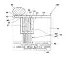
- FIG. 8schematically depicts an electronic device including a semiconductor device with at least one via according to an embodiment of the present invention.
- Embodiments of the present inventioninclude methods for fabricating conductive vias that extend through a fabrication substrate with a thickness (e.g., about 6 ⁇ m, about 25 ⁇ m, about 35 ⁇ m, about 50 ⁇ m, about 100 ⁇ m, about 150 ⁇ m, etc.) that is adequate for supporting integrated circuitry fabricated on an active, or front, surface of the substrate without consuming an undesirably large amount of real estate upon the active surface of the substrate.
- a thicknesse.g., about 6 ⁇ m, about 25 ⁇ m, about 35 ⁇ m, about 50 ⁇ m, about 100 ⁇ m, about 150 ⁇ m, etc.
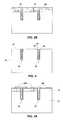
- FIG. 1a schematic representation of a fabrication substrate 10 comprising a semiconductor material and including an active surface 12 , which carries a plurality of active components 14 (e.g., transistors, resistors, etc.) is provided.
- the first end of at least one via hole, or “first via hole” 20is formed in active surface 12 .
- known wet etch processes or dry etch processese.g., reactive ion etch, or RIE
- a maske.g., a photomask
- each first via hole 20is the result of such material removal.
- the distance across (e.g., diameter of) each first via hole 20may be about 3 ⁇ m to about 6 ⁇ m.
- the depth of each first via hole 20may be about 15 ⁇ m to about 30 ⁇ m.
- first via holes 20 and some of the other features of conductive viasare fabricated before or during (e.g., as part of, concurrently, with, etc.) BEOL processing, in which conductive elements (e.g., contact plugs, conductive traces, contact pads, etc.) that interconnect active components 14 are fabricated.
- first via holes 20may communicate with apertures 18 that have been formed, by known techniques, through a dielectric film 16 (e.g., a borophosphosilicate glass (BPSG) film, a phosphosilicate glass (PSG) film, etc.).
- BPSGborophosphosilicate glass
- PSGphosphosilicate glass
- FIG. 2depicts the fabrication of one or more dielectric layers 22 and, optionally, barrier layers 24 on surfaces 21 of each first via hole 20 .
- a dielectric layer 22may be grown on (e.g., undoped silicon dioxide, etc.), deposited onto (e.g., a low-K dielectric material, a silicon nitride, a silicon oxynitride, etc.), or otherwise applied to surfaces 21 .
- one or more barrier layers 24may be fabricated over a dielectric layer 22 by known, suitable deposition techniques, such as chemical vapor deposition (CVD), including pulsed chemical vapor deposition (PCVD) and atomic layer deposition (ALD); physical vapor deposition (PVD) (e.g., sputtering); or other conductive film-forming techniques.
- CVDchemical vapor deposition
- PCVDpulsed chemical vapor deposition
- ALDatomic layer deposition
- PVDphysical vapor deposition
- sputteringor other conductive film-forming techniques.
- Dielectric layer 22 and all of its associated layershave a combined film thickness that is less than half the distance (e.g., radius) across each first via hole 20 in order to leave an opening 25 for the receipt of conductive material within each first via hole 20 .
- dielectric layers 22 , and any optional layers associated therewith, including barrier layer 24may remain over active surface 12 of fabrication substrate 10 until after conductive material has been introduced into opening 25 ( FIG. 2 ) within each first via hole 20 ( FIG. 1 ), as shown in FIG. 2 .
- each dielectric layer 22 and barrier layer 24may be effected as part of, or concurrently with, BEOL processing, in which corresponding dielectric films and optional barriers for conductive interconnects and/or conductive traces are formed.
- BEOL processingin which corresponding dielectric films and optional barriers for conductive interconnects and/or conductive traces are formed.
- dielectric layer 22 , any barrier layer 24 , and any other associated layersare deposited as part of BEOL processing one or more of these layers may, if desired, be patterned by known techniques.
- Such patterning techniquesmay include, but are not limited to, mask and etch processes, in which dielectric layer 22 and/or dielectric film 16 , as well as any associated adhesion or barrier layers, may be patterned to form apertures 26 (e.g., contact apertures) that expose underlying structures 27 (e.g., active-device, or conductivity doped, regions, conductive structures, etc.), as shown in FIG. 2A .
- apertures 26e.g., contact apertures
- underlying structures 27e.g., active-device, or conductivity doped, regions, conductive structures, etc.
- dielectric layer 22 and barrier layer 24may be polished or planarized (e.g., by chemical-mechanical polishing or planarization (CMP)), as shown in FIG. 2B .
- CMPchemical-mechanical polishing or planarization
- conductive material 28such as aluminum, copper, or any other suitable TSV material, may be introduced into the remainder (i.e., within opening 25 ( FIG. 2 )) of each first via hole 20 , as illustrated by FIGS. 2 through 2B .
- Known techniquesmay be used to introduce conductive material 28 into each first via hole 20 and over other locations of fabrication substrate 10 , including, in various non-limiting embodiments, CVD and PVD processes.
- conductive material 28may also be introduced into contact with any previously fabricated structures 27 (e.g., active-device, or conductivity doped, regions, conductive structures, etc.).
- FIG. 3illustrates, in embodiments where first conductive via end 30 processing is conducted before BEOL processing, conductive material 28 , as well as any layers (e.g., dielectric layer 22 , barrier layer 24 , etc.) located between conductive material 28 and active surface 12 of fabrication substrate 10 , may be completely removed from above active surface 12 of fabrication substrate 10 by known techniques, including, without limitation, polishing or planarization processes.
- first conductive via end 30 processing and BEOL processingare concurrently effected, as shown in FIGS. 2A and 2B , known techniques may be used to pattern conductive structures, such as the depicted conductive plugs 29 P and conductive lines 29 L, from conductive material 28 ( FIGS. 2A and 2B ) located over active surface 12 of fabrication substrate 10 .
- One or more first conductive via ends 30result from the processes shown in FIGS. 3 and 3A .
- BEOL processingmay be completed, as known in the art and shown in FIG. 4 .
- the thickness of fabrication substrate 10may be reduced (i.e., fabrication substrate 10 may be thinned) by removing material from its back side 13 .
- Materialmay be removed from back side 13 by known techniques, such as back grinding processes, with a wet etchant, or as otherwise known in the art.
- the thickness of fabrication substrate 10may, in some embodiments, be reduced from an initial thickness of about 700 ⁇ m to about 800 ⁇ m to a finished thickness, not including the thickness of any structures fabricated on or overlying active surface 12 , of about 150 ⁇ m or less (e.g., 120 ⁇ m, 100 ⁇ m, etc.).
- the resulting structureis shown, in inverted orientation, in FIG. 5 .
- processingcontinues to the fabrication of a second conductive via end 40 ( FIGS. 6 through 6B ) from back side 13 of fabrication substrate 10 .
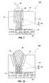
- each second via hole 32may be formed at a location to enable communication with a single corresponding first conductive via end 30 , as shown in FIG. 5 , or with a plurality of corresponding first conductive via ends 30 , as illustrated in FIG. 5A .
- the latter embodimentis particularly useful, among other possible purposes, for delivering power to integrated circuitry carried by active surface 12 through an electrode at back side 13 .
- connection of a single second conductive via end 40 to a plurality of first conductive via ends 30may reduce the number of contact pads (e.g., ball pads, pads that facilitate die-to-die interconnection, bond pads, etc.) that are required for a particular purpose (e.g., power delivery), which may enable a reduction in the overall sizes of semiconductor devices that incorporate this feature.
- contact padse.g., ball pads, pads that facilitate die-to-die interconnection, bond pads, etc.
- One or more second via holes 32may be formed in back side 13 by any suitable technique known in the art.
- each second via hole 32may be formed by laser ablation.
- known maske.g., photomask
- etche.g., wet etch, dry etch, etc.
- each resulting second via hole 32may have a height-aspect ratio as small as about 3:1 or even as small as about 2:1.
- the distance across (e.g., diameter of) a second via hole 32 that extends about 80 ⁇ m to about 90 ⁇ m into back side 13 of fabrication substrate 10may be about 50 ⁇ m.
- the distance across (e.g., diameter of) each second via hole 32may be much larger than the corresponding distance across the corresponding first via hole 20 (or via holes 20 ) within which the corresponding first conductive via end 30 is located, the likelihood that a second via hole 32 will be misaligned with its corresponding first via hole 20 (or via holes 20 ) is significantly reduced.
- each second via hole 32its surfaces 33 may be coated with one or more material layers, as shown in FIGS. 6 through 6B . Included among these material layers are one or more dielectric layers 34 .
- a dielectric layer 34may be grown on (e.g., undoped silicon dioxide, etc.), deposited onto (e.g., a low-K dielectric material, a silicon nitride, a silicon oxynitride, etc.), or otherwise applied to surfaces 33 .
- one or more barrier layers 35e.g., copper barriers, aluminum barriers, etc.
- one or more optional adhesion layersthat may enable the use of one or more desired types of dielectric and/or barrier materials may also be fabricated over surfaces 33 of each second via hole 32 .
- conductive material 37may be introduced into each second via hole 32 .
- conductive material 37may, in some embodiments, also be introduced over back side 13 of fabrication substrate 10 .
- a coating of conductive materialmay be formed over at least portions of back side 13 of fabrication substrate 10 (e.g., over material within each second via hole 32 ) at a later point during the processing of fabrication substrate 10 , as in the embodiment shown in FIG. 6B .
- conductive material 37may be introduced into each second via hole 32 in a manner that completely or substantially fills the opening that remains within second via hole 32 after dielectric layer 34 , and barrier layer 35 , and any other optional layer or layers, such as a plating seed layer, have been formed. In other embodiments, conductive material 37 may merely line or coat surfaces of the opening 36 that remains within each second via hole 32 . The degree to which conductive material 37 fills each opening 36 depends, at least in part, upon the conductive material introduction technique that is employed.
- conductive material introduction processesinclude, but are not limited to, plating processes (e.g., electroless plating, immersion plating, electrolytic plating, etc.), CVD, PVD, forcing a conductive paste (e.g., a metal paste, a solder paste, a paste or another solder alloy, etc.) into each opening, then reflowing the conductive paste, introducing a molten conductive material (e.g., a molten metal, a molten solder, another molten alloy, etc.) into each opening, then allowing the same to solidify, introducing a flowable conductive or conductor-filled polymer into each opening, then curing or otherwise causing or alloying the same to solidify, and any other suitable technique for introducing conductive material 37 into a blind ended via hole.
- plating processese.g., electroless plating, immersion plating, electrolytic plating, etc.
- CVDvapor deposition
- any space remaining within a second via hole 32 following the introduction of conductive material 37 into opening 36may remain open (see FIG. 6B ) or be completely or partially filled with another material (e.g., additional conductive material, an electrically insulative material, a thermally conductive material, etc.) (see FIGS. 6 and 6A ).
- another materiale.g., additional conductive material, an electrically insulative material, a thermally conductive material, etc.
- any conductive layers 37(as well as any underlying barrier layer 35 , etc.) and, possibly, any underlying layers (e.g., dielectric layer 34 , etc.) that extend across back side 13 of fabrication substrate 10 may be removed or patterned by known techniques. Suitable removal processes include, without limitation, CMP and wet etch processes, resulting in semiconductor devices such as the embodiments shown in FIGS. 7 and 7A . Patterning techniques include, but are not limited to, mask and etch processes, resulting, in some embodiments, in a semiconductor device that includes conductive features, such as conductive traces 44 and electrodes 46 on back side 13 , as are present in the embodiments that are depicted in FIGS. 6 through 6B .
- under-bump metallizationUBM
- ball-limiting metallurgyBBM
- the UBM, or BLMmay form one or more contact pads 48 , which are also referred to herein as “bottom contact pads,” over back side 13 of fabrication substrate 10 .
- Each contact pad 48facilitates the electrical connection of a discrete conductive element 50 ( FIG. 6 through 6B ) or a laterally extending intermediate conductive element 52 ( FIG. 7 ) to a corresponding second conductive via end 40 ( FIG. 7 ) or electrode 46 (e.g., the formation of discrete conductive element 50 on contact pad 48 , the securing of discrete conductive element 50 or a laterally extending intermediate conductive element 52 to contact pad 48 , etc.) ( FIGS. 6 through 6B ).
- the UBM, or BLMmay be formed over conductive material 37 that lines the surfaces of one or more openings 36 in back side 13 to provide an adhesion layer 48 ′ thereover.
- Adhesion layer 48 ′adheres to a discrete conductive element 50 that has been introduced to that opening and establishes electrical communication between discrete conductive element 50 and conductive material 37 .
- each discrete conductive element 50may comprise a ball, bump, pillar, stud, column, pin or other structure formed from a suitable conductive material, such as solder, another metal or metal alloy, a conductive or conductor-filled polymer, or the like.
- Intermediate conductive elements 52include, but are not limited to, bond wires, leads (including leads-over-chip (LOC) type leads, conductive elements that are carried by flexible dielectric materials, as in tape-automated bonding (TAB) type arrangements, thermocompression leads, etc.), and the like.
- Discrete conductive elements 50 and/or intermediate conductive elements 52which may be secured to bottom contact pads 48 , adhesion layer 48 ′, or top contact pads 49 , may electrically connect a semiconductor device 100 , 100 ′, 100 ′′, 100 ′′′ ( FIGS. 6 through 7A , respectively) according to the present invention to another electronic component, such as a carrier substrate (e.g., a circuit board, interposer, flexible substrate, etc.) leads, or another semiconductor device.
- a carrier substratee.g., a circuit board, interposer, flexible substrate, etc.
- a semiconductor device 100 , 100 ′, 100 ′′, 100 ′′′ that has been fabricated in accordance with one or more embodiments of the present inventionincludes a fabrication substrate 10 with a thickness (e.g., about 100 ⁇ m to about 150 ⁇ m) that provides adequate structural support for integrated circuitry that has been fabricated on active surface 12 .
- Conductive via ends 30 / 40 of semiconductor device 100 , 100 ′, 100 ′′, 100 ′′′enable the use of contact pads 48 , 49 and intermediate conductive elements 50 , 52 on back side 13 to communicate electrically with integrated circuitry carried by active surface 12 without occupying valuable area, or real estate, upon active surface 12 and, thus, without decreasing the optimal density of integrated circuitry on active surface 12 .
- all contact pads 48 of a semiconductor device 100 , 100 ′, 100 ′′, 100 ′′′may be carried by back side 13 of fabrication substrate 10 .
- all of the contact pads 48 of a semiconductor device 100 , 100 ′, 100 ′′, 100 ′′′are located on back side 13 of fabrication substrate 10 , there is no need to locate them over “dead” areas of the active surface, which frees up additional area, or real estate, on active surface 12 for integrated circuitry and increases the number of available circuit designs.
- a top contact pad 49may be located over active surface 12 of fabrication substrate 10 , while another, corresponding bottom contact pad 48 , which communicates with the same circuitry as the top contact pad 49 , is carried by back side 13 . Testing or burn-in may be effected through only the top contact pads 49 or through only the bottom contact pads 48 , preserving the other set of contact pads for use in connecting semiconductor device 100 , 100 ′, 100 ′′, 100 ′′′ to other electronic components, such as leads, a circuit board, or the like.
- contact pads 48are also separated from the integrated circuitry on active surface 12 by the thickness of fabrication substrate 10 rather than by much thinner dielectric layers that would otherwise separate contact pads located over active surface 12 from the integrated circuitry. As a result, there may be reduced potential for damaging the integrated circuitry as pressure is applied to contact pads 48 that are carried by back side 13 , as may occur during test and/or burn-in processes, in which probe elements are forced against contact pads.
- stresses that are induced on a substrate by rows of vias that extend completely through the semiconductor device and stresses resulting from mismatches in the coefficients of thermal expansion (CTEs) of a substrate and the material or materials of conductive vias extending entirely through the substratemay be reduced with the use of large diameter vias that extend only partially through a substrate.
- the elimination of at least some relatively large diameter conductive vias from the region of circuitry that is carried by the active surface of a semiconductor substratemay also relax design rules and/or enable improvements in the density with which such circuits are arranged.
- large diameter conductive vias that extend only partially through a substratemay be formed more quickly and, due to their lower aspect ratios, receive conductive material more quickly and reliably than conductive vias of comparable diameter that extend completely through a semiconductor device.
- the inclusion of large diameter conductive vias at the back side of a semiconductor devicemay enable the use of standard assembly equipment to form redistribution circuitry on the back side, which, due to the limited ability of such equipment to recognize smaller diameter, densely arranged conductive vias, would not otherwise be possible with small diameter conductive vias. Any of these contemplated advantages may lead to improved industrial scalability, product yields, and reliability when compared with the industrial scalability, product yields, and reliability that may be achieved when conventional processes are used to form conductive vias completely through semiconductor devices.
- an electronic device 200such as a computer, controller, cellular telephone, portable digital music player, digital camera, or the like, that includes at least one semiconductor device 100 , 100 ′, 100 ′′, 100 ′′′ including one or more vias 110 (see FIGS. 6-7B ) according to embodiments of the present invention is depicted.
- the present inventionincludes semiconductor devices with one or more conductive vias that include a relatively small diameter portion extending into an active surface of a fabrication substrate and a corresponding, relatively large diameter portion that extends into a back side of the fabrication substrate.
- this type of conductive viamay be fabricated by fanning the relatively small diameter portion before or during BEOL processing, while the large diameter portion of each conductive via may be fabricated after BEOL processing is complete.
- Electronic devices that include one or more semiconductor devices with such conductive viasare also disclosed.
Landscapes
- Engineering & Computer Science (AREA)
- Computer Hardware Design (AREA)
- Microelectronics & Electronic Packaging (AREA)
- Power Engineering (AREA)
- Physics & Mathematics (AREA)
- Condensed Matter Physics & Semiconductors (AREA)
- General Physics & Mathematics (AREA)
- Manufacturing & Machinery (AREA)
- Internal Circuitry In Semiconductor Integrated Circuit Devices (AREA)
Abstract
Description
Claims (34)
Priority Applications (1)
| Application Number | Priority Date | Filing Date | Title |
|---|---|---|---|
| US13/713,210US8872310B2 (en) | 2008-06-03 | 2012-12-13 | Semiconductor device structures and electronic devices including hybrid conductive vias, and methods of fabrication |
Applications Claiming Priority (3)
| Application Number | Priority Date | Filing Date | Title |
|---|---|---|---|
| US12/052,418US7939449B2 (en) | 2008-06-03 | 2008-06-03 | Methods of forming hybrid conductive vias including small dimension active surface ends and larger dimension back side ends |
| US13/085,112US8344514B2 (en) | 2008-06-03 | 2011-04-12 | Semiconductor device structures and electronic devices including same hybrid conductive vias |
| US13/713,210US8872310B2 (en) | 2008-06-03 | 2012-12-13 | Semiconductor device structures and electronic devices including hybrid conductive vias, and methods of fabrication |
Related Parent Applications (1)
| Application Number | Title | Priority Date | Filing Date |
|---|---|---|---|
| US13/085,112ContinuationUS8344514B2 (en) | 2008-06-03 | 2011-04-12 | Semiconductor device structures and electronic devices including same hybrid conductive vias |
Publications (2)
| Publication Number | Publication Date |
|---|---|
| US20130187289A1 US20130187289A1 (en) | 2013-07-25 |
| US8872310B2true US8872310B2 (en) | 2014-10-28 |
Family
ID=41378789
Family Applications (3)
| Application Number | Title | Priority Date | Filing Date |
|---|---|---|---|
| US12/052,418Active2029-04-02US7939449B2 (en) | 2008-06-03 | 2008-06-03 | Methods of forming hybrid conductive vias including small dimension active surface ends and larger dimension back side ends |
| US13/085,112ActiveUS8344514B2 (en) | 2008-06-03 | 2011-04-12 | Semiconductor device structures and electronic devices including same hybrid conductive vias |
| US13/713,210ActiveUS8872310B2 (en) | 2008-06-03 | 2012-12-13 | Semiconductor device structures and electronic devices including hybrid conductive vias, and methods of fabrication |
Family Applications Before (2)
| Application Number | Title | Priority Date | Filing Date |
|---|---|---|---|
| US12/052,418Active2029-04-02US7939449B2 (en) | 2008-06-03 | 2008-06-03 | Methods of forming hybrid conductive vias including small dimension active surface ends and larger dimension back side ends |
| US13/085,112ActiveUS8344514B2 (en) | 2008-06-03 | 2011-04-12 | Semiconductor device structures and electronic devices including same hybrid conductive vias |
Country Status (3)
| Country | Link |
|---|---|
| US (3) | US7939449B2 (en) |
| SG (1) | SG157351A1 (en) |
| TW (2) | TWI387052B (en) |
Cited By (4)
| Publication number | Priority date | Publication date | Assignee | Title |
|---|---|---|---|---|
| US20180350733A1 (en)* | 2015-09-17 | 2018-12-06 | Semiconductor Components Industries, Llc | Through-substrate via structure and method of manufacture |
| US20190067200A1 (en)* | 2015-11-30 | 2019-02-28 | Taiwan Semiconductor Manufacturing Co., Ltd. | Structure for stacked logic performance improvement |
| US11342189B2 (en) | 2015-09-17 | 2022-05-24 | Semiconductor Components Industries, Llc | Semiconductor packages with die including cavities and related methods |
| US12218034B2 (en) | 2020-11-16 | 2025-02-04 | Changxin Memory Technologies, Inc. | Semiconductor structure and method for manufacturing semiconductor structure |
Families Citing this family (64)
| Publication number | Priority date | Publication date | Assignee | Title |
|---|---|---|---|---|
| US8569876B2 (en) | 2006-11-22 | 2013-10-29 | Tessera, Inc. | Packaged semiconductor chips with array |
| US8405196B2 (en) | 2007-03-05 | 2013-03-26 | DigitalOptics Corporation Europe Limited | Chips having rear contacts connected by through vias to front contacts |
| WO2009017835A2 (en) | 2007-07-31 | 2009-02-05 | Tessera, Inc. | Semiconductor packaging process using through silicon vias |
| US7939449B2 (en)* | 2008-06-03 | 2011-05-10 | Micron Technology, Inc. | Methods of forming hybrid conductive vias including small dimension active surface ends and larger dimension back side ends |
| US7968460B2 (en)* | 2008-06-19 | 2011-06-28 | Micron Technology, Inc. | Semiconductor with through-substrate interconnect |
| US8378495B2 (en)* | 2009-08-10 | 2013-02-19 | Texas Instruments Incorporated | Integrated circuit (IC) having TSVS with dielectric crack suppression structures |
| US8791549B2 (en)* | 2009-09-22 | 2014-07-29 | Taiwan Semiconductor Manufacturing Company, Ltd. | Wafer backside interconnect structure connected to TSVs |
| JP2011082450A (en) | 2009-10-09 | 2011-04-21 | Elpida Memory Inc | Semiconductor device, and information processing system with the same |
| US8339155B2 (en)* | 2009-11-25 | 2012-12-25 | Taiwan Semiconductor Manufacturing Company, Ltd. | System and method for detecting soft-fails |
| JP5209075B2 (en)* | 2010-05-21 | 2013-06-12 | 有限会社 ナプラ | Electronic device and manufacturing method thereof |
| US8492878B2 (en)* | 2010-07-21 | 2013-07-23 | International Business Machines Corporation | Metal-contamination-free through-substrate via structure |
| US9640437B2 (en)* | 2010-07-23 | 2017-05-02 | Tessera, Inc. | Methods of forming semiconductor elements using micro-abrasive particle stream |
| US8796135B2 (en) | 2010-07-23 | 2014-08-05 | Tessera, Inc. | Microelectronic elements with rear contacts connected with via first or via middle structures |
| US8791575B2 (en) | 2010-07-23 | 2014-07-29 | Tessera, Inc. | Microelectronic elements having metallic pads overlying vias |
| US8384430B2 (en)* | 2010-08-16 | 2013-02-26 | Taiwan Semiconductor Manufacturing Company, Ltd. | RC delay detectors with high sensitivity for through substrate vias |
| US8492260B2 (en) | 2010-08-30 | 2013-07-23 | Semionductor Components Industries, LLC | Processes of forming an electronic device including a feature in a trench |
| US9437561B2 (en)* | 2010-09-09 | 2016-09-06 | Advanced Micro Devices, Inc. | Semiconductor chip with redundant thru-silicon-vias |
| US8847380B2 (en) | 2010-09-17 | 2014-09-30 | Tessera, Inc. | Staged via formation from both sides of chip |
| US8610259B2 (en) | 2010-09-17 | 2013-12-17 | Tessera, Inc. | Multi-function and shielded 3D interconnects |
| US8587126B2 (en) | 2010-12-02 | 2013-11-19 | Tessera, Inc. | Stacked microelectronic assembly with TSVs formed in stages with plural active chips |
| US8736066B2 (en) | 2010-12-02 | 2014-05-27 | Tessera, Inc. | Stacked microelectronic assemby with TSVS formed in stages and carrier above chip |
| US8637968B2 (en) | 2010-12-02 | 2014-01-28 | Tessera, Inc. | Stacked microelectronic assembly having interposer connecting active chips |
| US8610264B2 (en) | 2010-12-08 | 2013-12-17 | Tessera, Inc. | Compliant interconnects in wafers |
| FR2969381A1 (en)* | 2010-12-21 | 2012-06-22 | St Microelectronics Crolles 2 | Electronic chip, has set of connection pillars electrically connected with vias, where pillars form protuberant regions relative to substrate and are provided with portion embedded in housing formed in thickness of substrate |
| DE102010056056A1 (en)* | 2010-12-23 | 2012-06-28 | Osram Opto Semiconductors Gmbh | Method for producing an electrical connection carrier |
| US8975751B2 (en)* | 2011-04-22 | 2015-03-10 | Tessera, Inc. | Vias in porous substrates |
| US8853072B2 (en) | 2011-06-06 | 2014-10-07 | Micron Technology, Inc. | Methods of forming through-substrate interconnects |
| FR2978296A1 (en)* | 2011-07-20 | 2013-01-25 | St Microelectronics Crolles 2 | ELECTRONIC CHIP COMPRISING CONNECTION PILLARS, AND METHOD OF MANUFACTURE |
| US8394718B1 (en) | 2011-09-12 | 2013-03-12 | International Business Machines Corporation | Methods of forming self-aligned through silicon via |
| US9689835B2 (en) | 2011-10-31 | 2017-06-27 | Taiwan Semiconductor Manufacturing Company, Ltd. | Amplified dual-gate bio field effect transistor |
| US9459234B2 (en) | 2011-10-31 | 2016-10-04 | Taiwan Semiconductor Manufacturing Company, Ltd., (“TSMC”) | CMOS compatible BioFET |
| FR2983638A1 (en)* | 2011-12-02 | 2013-06-07 | St Microelectronics Sa | METHOD FOR FORMING AN INTEGRATED CIRCUIT |
| US9257392B2 (en)* | 2012-04-11 | 2016-02-09 | Mediatek Inc. | Semiconductor package with through silicon via interconnect |
| FR2994023B1 (en)* | 2012-07-25 | 2015-04-10 | Commissariat Energie Atomique | METHOD FOR PRODUCING VIAS |
| US8981533B2 (en)* | 2012-09-13 | 2015-03-17 | Semiconductor Components Industries, Llc | Electronic device including a via and a conductive structure, a process of forming the same, and an interposer |
| US9123789B2 (en)* | 2013-01-23 | 2015-09-01 | United Microelectronics Corp. | Chip with through silicon via electrode and method of forming the same |
| US20150187701A1 (en) | 2013-03-12 | 2015-07-02 | Taiwan Semiconductor Manufacturing Company, Ltd. | Semiconductor Devices and Methods of Manufacture Thereof |
| US9076715B2 (en) | 2013-03-12 | 2015-07-07 | Taiwan Semiconductor Manufacturing Company, Ltd. | Interconnect structure for connecting dies and methods of forming the same |
| US9764153B2 (en)* | 2013-03-14 | 2017-09-19 | Taiwan Semiconductor Manufacturing Company, Ltd. | Interconnect structure and method of forming same |
| US20140332952A1 (en)* | 2013-05-09 | 2014-11-13 | United Microelectronics Corp. | Semiconductor structure and method for testing the same |
| US20150021773A1 (en)* | 2013-07-22 | 2015-01-22 | Conversant Intellectual Property Management Inc. | Through Semiconductor via Structure with Reduced Stress Proximity Effect |
| US9147642B2 (en)* | 2013-10-31 | 2015-09-29 | Nanya Technology Corporation | Integrated circuit device |
| US10056353B2 (en) | 2013-12-19 | 2018-08-21 | Taiwan Semiconductor Manufacturing Company, Ltd. | 3DIC interconnect apparatus and method |
| US9412719B2 (en) | 2013-12-19 | 2016-08-09 | Taiwan Semiconductor Manufacturing Company, Ltd. | 3DIC interconnect apparatus and method |
| US9425150B2 (en) | 2014-02-13 | 2016-08-23 | Taiwan Semiconductor Manufacturing Company, Ltd. | Multi-via interconnect structure and method of manufacture |
| US9543257B2 (en)* | 2014-05-29 | 2017-01-10 | Taiwan Semiconductor Manufacturing Company, Ltd. | 3DIC interconnect devices and methods of forming same |
| US9455158B2 (en) | 2014-05-30 | 2016-09-27 | Taiwan Semiconductor Manufacturing Company, Ltd. | 3DIC interconnect devices and methods of forming same |
| US9653381B2 (en) | 2014-06-17 | 2017-05-16 | Micron Technology, Inc. | Semiconductor structures and die assemblies including conductive vias and thermally conductive elements and methods of forming such structures |
| US9449914B2 (en) | 2014-07-17 | 2016-09-20 | Taiwan Semiconductor Manufacturing Company, Ltd. | Stacked integrated circuits with redistribution lines |
| TWI571983B (en)* | 2014-11-25 | 2017-02-21 | 矽品精密工業股份有限公司 | Electronic package and method of manufacture |
| US9812354B2 (en) | 2015-05-15 | 2017-11-07 | Semiconductor Components Industries, Llc | Process of forming an electronic device including a material defining a void |
| US9472490B1 (en)* | 2015-08-12 | 2016-10-18 | GlobalFoundries, Inc. | IC structure with recessed solder bump area and methods of forming same |
| JP6544160B2 (en)* | 2015-09-09 | 2019-07-17 | 三菱電機株式会社 | Semiconductor device |
| US20170323863A1 (en)* | 2016-05-09 | 2017-11-09 | Amkor Technology, Inc. | Semiconductor device and manufacturing method thereof |
| US10130302B2 (en) | 2016-06-29 | 2018-11-20 | International Business Machines Corporation | Via and trench filling using injection molded soldering |
| US20180005887A1 (en)* | 2016-06-30 | 2018-01-04 | International Business Machines Corporation | Through-silicon via with injection molded fill |
| US10949597B2 (en)* | 2018-07-16 | 2021-03-16 | Taiwan Semiconductor Manufacturing Co., Ltd. | Through-silicon vias in integrated circuit packaging |
| KR102504834B1 (en)* | 2019-03-11 | 2023-02-28 | 삼성전자 주식회사 | Integrated circuit chip, method of manufacturing integrated circuit chip, and integrated circuit package and display apparatus including integrated circuit chip |
| KR20220033598A (en) | 2020-09-08 | 2022-03-17 | 삼성전자주식회사 | Semiconductor package |
| TWI823299B (en)* | 2022-03-18 | 2023-11-21 | 邱志威 | Method for manufacturing semiconductor structure with power rails under transistors and semiconductor structure with power rails under transistors |
| CN115376994A (en)* | 2021-05-19 | 2022-11-22 | 邱志威 | Semiconductor structure with power supply connection structure under transistor and manufacturing method thereof |
| CN115621192A (en)* | 2021-07-13 | 2023-01-17 | 长鑫存储技术有限公司 | Semiconductor structure and forming method thereof |
| US11830865B2 (en)* | 2021-10-26 | 2023-11-28 | Nanya Technology Corporation | Semiconductor device with redistribution structure and method for fabricating the same |
| WO2024036481A1 (en)* | 2022-08-16 | 2024-02-22 | 华为技术有限公司 | Chip package structure, electronic device, and packaging method for chip package structure |
Citations (17)
| Publication number | Priority date | Publication date | Assignee | Title |
|---|---|---|---|---|
| US20020066960A1 (en) | 2000-04-11 | 2002-06-06 | Zoltan Ring | Method of forming vias in silicon carbide and resulting devices and circuits |
| US6495454B2 (en) | 1998-09-23 | 2002-12-17 | Intel Corporation | Substrate interconnect for power distribution on integrated circuits |
| US20030017650A1 (en) | 2000-09-12 | 2003-01-23 | International Business Machines Corporation | Semiconductor chip structures with embedded thermal conductors and a thermal sink disposed over opposing substrate surfaces |
| US20030111733A1 (en) | 2001-12-19 | 2003-06-19 | International Business Machines Corporation | Chip and wafer integration process using vertical connections |
| US20030137056A1 (en) | 2002-01-18 | 2003-07-24 | Fujitsu Limited | Circuit substrate and method for fabricating the same |
| US20050067716A1 (en) | 2003-01-02 | 2005-03-31 | Cree, Inc. | Group III nitride based flip-chip integrated circuit and method for fabricating |
| US20050255691A1 (en) | 1999-10-08 | 2005-11-17 | Applied Materials, Inc. | Self-ionized and inductively-coupled plasma for sputtering and resputtering |
| US7057274B2 (en) | 2001-10-17 | 2006-06-06 | Hymite A/S | Semiconductor structures having through-holes sealed with feed-through metalization |
| US20060163740A1 (en) | 2004-02-24 | 2006-07-27 | Ibiden Co., Ltd. | Semiconductor mounting board |
| US20060223301A1 (en) | 2004-12-17 | 2006-10-05 | Serge Vanhaelemeersch | Formation of deep via airgaps for three dimensional wafer to wafer interconnect |
| US7125786B2 (en) | 2000-04-11 | 2006-10-24 | Cree, Inc. | Method of forming vias in silicon carbide and resulting devices and circuits |
| US7576404B2 (en) | 2005-12-16 | 2009-08-18 | Icemos Technology Ltd. | Backlit photodiode and method of manufacturing a backlit photodiode |
| US20100155961A1 (en) | 2006-04-19 | 2010-06-24 | Ando Feyh | Micromechanical component having wafer through-plating and corresponding production method |
| US20100176469A1 (en) | 2007-06-06 | 2010-07-15 | Peter Schmollngruber | Micromechanical component and method for producing a micromechanical component |
| US20100187647A1 (en) | 2006-09-15 | 2010-07-29 | Peter Steven Bui | High Density Photodiodes |
| US20100207274A1 (en) | 2005-08-15 | 2010-08-19 | Kabushiki Kaisha Toshiba | Semiconductor device and its manufacturing method |
| US7939449B2 (en)* | 2008-06-03 | 2011-05-10 | Micron Technology, Inc. | Methods of forming hybrid conductive vias including small dimension active surface ends and larger dimension back side ends |
- 2008
- 2008-06-03USUS12/052,418patent/US7939449B2/enactiveActive
- 2009
- 2009-06-03TWTW098118448Apatent/TWI387052B/enactive
- 2009-06-03TWTW101145864Apatent/TWI479601B/enactive
- 2009-06-03SGSG200903782-1Apatent/SG157351A1/enunknown
- 2011
- 2011-04-12USUS13/085,112patent/US8344514B2/enactiveActive
- 2012
- 2012-12-13USUS13/713,210patent/US8872310B2/enactiveActive
Patent Citations (29)
| Publication number | Priority date | Publication date | Assignee | Title |
|---|---|---|---|---|
| US6495454B2 (en) | 1998-09-23 | 2002-12-17 | Intel Corporation | Substrate interconnect for power distribution on integrated circuits |
| US20050255691A1 (en) | 1999-10-08 | 2005-11-17 | Applied Materials, Inc. | Self-ionized and inductively-coupled plasma for sputtering and resputtering |
| US20090233438A1 (en) | 1999-10-08 | 2009-09-17 | Applied Materials, Inc. | Self-ionized and inductively-coupled plasma for sputtering and resputtering |
| US6515303B2 (en) | 2000-04-11 | 2003-02-04 | Cree, Inc. | Method of forming vias in silicon carbide and resulting devices and circuits |
| US7125786B2 (en) | 2000-04-11 | 2006-10-24 | Cree, Inc. | Method of forming vias in silicon carbide and resulting devices and circuits |
| US20020066960A1 (en) | 2000-04-11 | 2002-06-06 | Zoltan Ring | Method of forming vias in silicon carbide and resulting devices and circuits |
| US20030017650A1 (en) | 2000-09-12 | 2003-01-23 | International Business Machines Corporation | Semiconductor chip structures with embedded thermal conductors and a thermal sink disposed over opposing substrate surfaces |
| US7057274B2 (en) | 2001-10-17 | 2006-06-06 | Hymite A/S | Semiconductor structures having through-holes sealed with feed-through metalization |
| US20050121711A1 (en) | 2001-12-19 | 2005-06-09 | Pogge H. B. | Chip and wafer integration process using vertical connections |
| US7388277B2 (en) | 2001-12-19 | 2008-06-17 | International Business Machines Corporation | Chip and wafer integration process using vertical connections |
| US6599778B2 (en) | 2001-12-19 | 2003-07-29 | International Business Machines Corporation | Chip and wafer integration process using vertical connections |
| US7564118B2 (en) | 2001-12-19 | 2009-07-21 | International Business Machines Corporation | Chip and wafer integration process using vertical connections |
| US20030111733A1 (en) | 2001-12-19 | 2003-06-19 | International Business Machines Corporation | Chip and wafer integration process using vertical connections |
| US20080230891A1 (en) | 2001-12-19 | 2008-09-25 | International Business Machines Corporation | Chip and wafer integration process using vertical connections |
| US20030137056A1 (en) | 2002-01-18 | 2003-07-24 | Fujitsu Limited | Circuit substrate and method for fabricating the same |
| US20070155174A1 (en) | 2002-01-18 | 2007-07-05 | Fijitsu Limited | Circuit substrate and method for fabricating the same |
| US20050067716A1 (en) | 2003-01-02 | 2005-03-31 | Cree, Inc. | Group III nitride based flip-chip integrated circuit and method for fabricating |
| US20060163740A1 (en) | 2004-02-24 | 2006-07-27 | Ibiden Co., Ltd. | Semiconductor mounting board |
| US7338896B2 (en) | 2004-12-17 | 2008-03-04 | Interuniversitair Microelektronica Centrum (Imec) | Formation of deep via airgaps for three dimensional wafer to wafer interconnect |
| US20060223301A1 (en) | 2004-12-17 | 2006-10-05 | Serge Vanhaelemeersch | Formation of deep via airgaps for three dimensional wafer to wafer interconnect |
| US20100207274A1 (en) | 2005-08-15 | 2010-08-19 | Kabushiki Kaisha Toshiba | Semiconductor device and its manufacturing method |
| US7576404B2 (en) | 2005-12-16 | 2009-08-18 | Icemos Technology Ltd. | Backlit photodiode and method of manufacturing a backlit photodiode |
| US20100155961A1 (en) | 2006-04-19 | 2010-06-24 | Ando Feyh | Micromechanical component having wafer through-plating and corresponding production method |
| US20100187647A1 (en) | 2006-09-15 | 2010-07-29 | Peter Steven Bui | High Density Photodiodes |
| US20110278690A1 (en) | 2006-09-15 | 2011-11-17 | Peter Steven Bui | High Density Photodiodes |
| US20100176469A1 (en) | 2007-06-06 | 2010-07-15 | Peter Schmollngruber | Micromechanical component and method for producing a micromechanical component |
| US7939449B2 (en)* | 2008-06-03 | 2011-05-10 | Micron Technology, Inc. | Methods of forming hybrid conductive vias including small dimension active surface ends and larger dimension back side ends |
| US20110180936A1 (en) | 2008-06-03 | 2011-07-28 | Micron Technology, Inc. | Semiconductor device structures and electronic devices including same hybrid conductive vias |
| US8344514B2 (en)* | 2008-06-03 | 2013-01-01 | Micron Technology, Inc. | Semiconductor device structures and electronic devices including same hybrid conductive vias |
Cited By (13)
| Publication number | Priority date | Publication date | Assignee | Title |
|---|---|---|---|---|
| US12119294B2 (en) | 2015-09-17 | 2024-10-15 | Semiconductor Components Industries, Llc | Through-substrate via structure and method of manufacture |
| US10446480B2 (en)* | 2015-09-17 | 2019-10-15 | Semiconductor Components Industries, Llc | Through-substrate via structure and method of manufacture |
| US10950534B2 (en) | 2015-09-17 | 2021-03-16 | Semiconductor Components Industries, Llc | Through-substrate via structure and method of manufacture |
| US11342189B2 (en) | 2015-09-17 | 2022-05-24 | Semiconductor Components Industries, Llc | Semiconductor packages with die including cavities and related methods |
| US11616008B2 (en) | 2015-09-17 | 2023-03-28 | Semiconductor Components Industries, Llc | Through-substrate via structure and method of manufacture |
| US11908699B2 (en) | 2015-09-17 | 2024-02-20 | Semiconductor Components Industries, Llc | Semiconductor packages with die including cavities |
| US20180350733A1 (en)* | 2015-09-17 | 2018-12-06 | Semiconductor Components Industries, Llc | Through-substrate via structure and method of manufacture |
| US12374554B2 (en) | 2015-09-17 | 2025-07-29 | Semiconductor Components Industries, Llc | Semiconductor packages with die including cavities and related methods |
| US20190067200A1 (en)* | 2015-11-30 | 2019-02-28 | Taiwan Semiconductor Manufacturing Co., Ltd. | Structure for stacked logic performance improvement |
| US10566288B2 (en)* | 2015-11-30 | 2020-02-18 | Taiwan Semiconductor Manufacturing Co., Ltd. | Structure for standard logic performance improvement having a back-side through-substrate-via |
| US11107767B2 (en) | 2015-11-30 | 2021-08-31 | Taiwan Semiconductor Manufacturing Company, Ltd. | Structure for standard logic performance improvement having a back-side through-substrate-via |
| US12142569B2 (en) | 2015-11-30 | 2024-11-12 | Taiwan Semiconductor Manufacturing Company, Ltd. | Integrated chip for standard logic performance improvement having a back-side through-substrate-via and method for forming the integrated chip |
| US12218034B2 (en) | 2020-11-16 | 2025-02-04 | Changxin Memory Technologies, Inc. | Semiconductor structure and method for manufacturing semiconductor structure |
Also Published As
| Publication number | Publication date |
|---|---|
| US7939449B2 (en) | 2011-05-10 |
| US20090294983A1 (en) | 2009-12-03 |
| US20110180936A1 (en) | 2011-07-28 |
| SG157351A1 (en) | 2009-12-29 |
| TWI387052B (en) | 2013-02-21 |
| US20130187289A1 (en) | 2013-07-25 |
| TW201312694A (en) | 2013-03-16 |
| US8344514B2 (en) | 2013-01-01 |
| TWI479601B (en) | 2015-04-01 |
| TW201010005A (en) | 2010-03-01 |
Similar Documents
| Publication | Publication Date | Title |
|---|---|---|
| US8872310B2 (en) | Semiconductor device structures and electronic devices including hybrid conductive vias, and methods of fabrication | |
| US11688693B2 (en) | Semiconductor packages and method of manufacture | |
| US8736028B2 (en) | Semiconductor device structures and printed circuit boards comprising semiconductor devices | |
| TWI437679B (en) | Substrate interconnections having different sizes | |
| US8846523B2 (en) | Process of forming through-silicon via structure | |
| US8791011B2 (en) | Through-silicon via structure formation process | |
| CN101752336B (en) | Semiconductor device and manufacturing method thereof | |
| US12113036B2 (en) | Semiconductor package and manufacturing method thereof | |
| US20140225277A1 (en) | Isolation Structure for Stacked Dies | |
| TW201724192A (en) | Integrated circuit structure and method for manufacturing the same | |
| WO2012037140A2 (en) | Integrated circuits with through-substrate vias | |
| US11894312B2 (en) | Semiconductor packages and method of manufacture | |
| US11769704B2 (en) | Semiconductor structure having an anti-arcing pattern disposed on a passivation layer and a post passivation layer disposed on the anti-arcing pattern | |
| TWI780704B (en) | Semiconductor package device and method for forming the same | |
| US20240363496A1 (en) | Semiconductor package and method for manufacturing the same | |
| CN115172272A (en) | High-aspect-ratio TSV (through silicon via) electric communication structure and manufacturing method thereof | |
| TWI888880B (en) | Semiconductor device and method for forming same | |
| US20080157382A1 (en) | Direct termination of a wiring metal in a semiconductor device |
Legal Events
| Date | Code | Title | Description |
|---|---|---|---|
| FEPP | Fee payment procedure | Free format text:PAYOR NUMBER ASSIGNED (ORIGINAL EVENT CODE: ASPN); ENTITY STATUS OF PATENT OWNER: LARGE ENTITY | |
| STCF | Information on status: patent grant | Free format text:PATENTED CASE | |
| AS | Assignment | Owner name:U.S. BANK NATIONAL ASSOCIATION, AS COLLATERAL AGENT, CALIFORNIA Free format text:SECURITY INTEREST;ASSIGNOR:MICRON TECHNOLOGY, INC.;REEL/FRAME:038669/0001 Effective date:20160426 Owner name:U.S. BANK NATIONAL ASSOCIATION, AS COLLATERAL AGEN Free format text:SECURITY INTEREST;ASSIGNOR:MICRON TECHNOLOGY, INC.;REEL/FRAME:038669/0001 Effective date:20160426 | |
| AS | Assignment | Owner name:MORGAN STANLEY SENIOR FUNDING, INC., AS COLLATERAL AGENT, MARYLAND Free format text:PATENT SECURITY AGREEMENT;ASSIGNOR:MICRON TECHNOLOGY, INC.;REEL/FRAME:038954/0001 Effective date:20160426 Owner name:MORGAN STANLEY SENIOR FUNDING, INC., AS COLLATERAL Free format text:PATENT SECURITY AGREEMENT;ASSIGNOR:MICRON TECHNOLOGY, INC.;REEL/FRAME:038954/0001 Effective date:20160426 | |
| AS | Assignment | Owner name:U.S. BANK NATIONAL ASSOCIATION, AS COLLATERAL AGENT, CALIFORNIA Free format text:CORRECTIVE ASSIGNMENT TO CORRECT THE REPLACE ERRONEOUSLY FILED PATENT #7358718 WITH THE CORRECT PATENT #7358178 PREVIOUSLY RECORDED ON REEL 038669 FRAME 0001. ASSIGNOR(S) HEREBY CONFIRMS THE SECURITY INTEREST;ASSIGNOR:MICRON TECHNOLOGY, INC.;REEL/FRAME:043079/0001 Effective date:20160426 Owner name:U.S. BANK NATIONAL ASSOCIATION, AS COLLATERAL AGEN Free format text:CORRECTIVE ASSIGNMENT TO CORRECT THE REPLACE ERRONEOUSLY FILED PATENT #7358718 WITH THE CORRECT PATENT #7358178 PREVIOUSLY RECORDED ON REEL 038669 FRAME 0001. ASSIGNOR(S) HEREBY CONFIRMS THE SECURITY INTEREST;ASSIGNOR:MICRON TECHNOLOGY, INC.;REEL/FRAME:043079/0001 Effective date:20160426 | |
| MAFP | Maintenance fee payment | Free format text:PAYMENT OF MAINTENANCE FEE, 4TH YEAR, LARGE ENTITY (ORIGINAL EVENT CODE: M1551) Year of fee payment:4 | |
| AS | Assignment | Owner name:JPMORGAN CHASE BANK, N.A., AS COLLATERAL AGENT, ILLINOIS Free format text:SECURITY INTEREST;ASSIGNORS:MICRON TECHNOLOGY, INC.;MICRON SEMICONDUCTOR PRODUCTS, INC.;REEL/FRAME:047540/0001 Effective date:20180703 Owner name:JPMORGAN CHASE BANK, N.A., AS COLLATERAL AGENT, IL Free format text:SECURITY INTEREST;ASSIGNORS:MICRON TECHNOLOGY, INC.;MICRON SEMICONDUCTOR PRODUCTS, INC.;REEL/FRAME:047540/0001 Effective date:20180703 | |
| AS | Assignment | Owner name:MICRON TECHNOLOGY, INC., IDAHO Free format text:RELEASE BY SECURED PARTY;ASSIGNOR:U.S. BANK NATIONAL ASSOCIATION, AS COLLATERAL AGENT;REEL/FRAME:047243/0001 Effective date:20180629 | |
| AS | Assignment | Owner name:MICRON TECHNOLOGY, INC., IDAHO Free format text:RELEASE BY SECURED PARTY;ASSIGNOR:MORGAN STANLEY SENIOR FUNDING, INC., AS COLLATERAL AGENT;REEL/FRAME:050937/0001 Effective date:20190731 | |
| AS | Assignment | Owner name:MICRON SEMICONDUCTOR PRODUCTS, INC., IDAHO Free format text:RELEASE BY SECURED PARTY;ASSIGNOR:JPMORGAN CHASE BANK, N.A., AS COLLATERAL AGENT;REEL/FRAME:051028/0001 Effective date:20190731 Owner name:MICRON TECHNOLOGY, INC., IDAHO Free format text:RELEASE BY SECURED PARTY;ASSIGNOR:JPMORGAN CHASE BANK, N.A., AS COLLATERAL AGENT;REEL/FRAME:051028/0001 Effective date:20190731 | |
| MAFP | Maintenance fee payment | Free format text:PAYMENT OF MAINTENANCE FEE, 8TH YEAR, LARGE ENTITY (ORIGINAL EVENT CODE: M1552); ENTITY STATUS OF PATENT OWNER: LARGE ENTITY Year of fee payment:8 |