US8872079B2 - Apparatus for preparing a food item in a microwave oven - Google Patents
Apparatus for preparing a food item in a microwave ovenDownload PDFInfo
- Publication number
- US8872079B2 US8872079B2US12/378,574US37857409AUS8872079B2US 8872079 B2US8872079 B2US 8872079B2US 37857409 AUS37857409 AUS 37857409AUS 8872079 B2US8872079 B2US 8872079B2
- Authority
- US
- United States
- Prior art keywords
- press
- formed integral
- tray
- cover
- laminate
- Prior art date
- Legal status (The legal status is an assumption and is not a legal conclusion. Google has not performed a legal analysis and makes no representation as to the accuracy of the status listed.)
- Active, expires
Links
- 235000013305foodNutrition0.000titleclaimsabstractdescription64
- 238000010438heat treatmentMethods0.000claimsabstractdescription81
- 239000000463materialSubstances0.000claimsabstractdescription54
- 230000002452interceptive effectEffects0.000claimsabstractdescription43
- 230000002093peripheral effectEffects0.000claimsdescription15
- 238000007373indentationMethods0.000claimsdescription12
- 239000011087paperboardSubstances0.000claimsdescription11
- 229920006254polymer filmPolymers0.000claimsdescription10
- 239000000853adhesiveSubstances0.000claims2
- 230000001070adhesive effectEffects0.000claims2
- 238000000034methodMethods0.000description8
- 229910052751metalInorganic materials0.000description6
- 239000002184metalSubstances0.000description6
- 238000013022ventingMethods0.000description6
- 230000007423decreaseEffects0.000description5
- 239000000758substrateSubstances0.000description5
- XEEYBQQBJWHFJM-UHFFFAOYSA-NIronChemical compound[Fe]XEEYBQQBJWHFJM-UHFFFAOYSA-N0.000description4
- 229910052782aluminiumInorganic materials0.000description4
- XAGFODPZIPBFFR-UHFFFAOYSA-NaluminiumChemical compound[Al]XAGFODPZIPBFFR-UHFFFAOYSA-N0.000description4
- 230000007246mechanismEffects0.000description4
- 229910001092metal group alloyInorganic materials0.000description4
- 239000000123paperSubstances0.000description4
- 230000002708enhancing effectEffects0.000description3
- -1for exampleSubstances0.000description3
- 229910044991metal oxideInorganic materials0.000description3
- 150000004706metal oxidesChemical class0.000description3
- 239000007787solidSubstances0.000description3
- RYGMFSIKBFXOCR-UHFFFAOYSA-NCopperChemical compound[Cu]RYGMFSIKBFXOCR-UHFFFAOYSA-N0.000description2
- PXHVJJICTQNCMI-UHFFFAOYSA-NNickelChemical compound[Ni]PXHVJJICTQNCMI-UHFFFAOYSA-N0.000description2
- ATJFFYVFTNAWJD-UHFFFAOYSA-NTinChemical compound[Sn]ATJFFYVFTNAWJD-UHFFFAOYSA-N0.000description2
- 229910045601alloyInorganic materials0.000description2
- 239000000956alloySubstances0.000description2
- 230000008901benefitEffects0.000description2
- 230000008859changeEffects0.000description2
- 239000011248coating agentSubstances0.000description2
- 238000000576coating methodMethods0.000description2
- 238000010411cookingMethods0.000description2
- 229910052802copperInorganic materials0.000description2
- 239000010949copperSubstances0.000description2
- 230000000694effectsEffects0.000description2
- 239000011888foilSubstances0.000description2
- 229910052742ironInorganic materials0.000description2
- 230000001788irregularEffects0.000description2
- 230000008569processEffects0.000description2
- 229910001220stainless steelInorganic materials0.000description2
- 239000010935stainless steelSubstances0.000description2
- 229910052718tinInorganic materials0.000description2
- 230000000007visual effectEffects0.000description2
- 239000011800void materialSubstances0.000description2
- 229920000298CellophanePolymers0.000description1
- VYZAMTAEIAYCRO-UHFFFAOYSA-NChromiumChemical compound[Cr]VYZAMTAEIAYCRO-UHFFFAOYSA-N0.000description1
- FYYHWMGAXLPEAU-UHFFFAOYSA-NMagnesiumChemical compound[Mg]FYYHWMGAXLPEAU-UHFFFAOYSA-N0.000description1
- 229910001182Mo alloyInorganic materials0.000description1
- 239000004952PolyamideSubstances0.000description1
- 239000004642PolyimideSubstances0.000description1
- QAOWNCQODCNURD-UHFFFAOYSA-LSulfateChemical compound[O-]S([O-])(=O)=OQAOWNCQODCNURD-UHFFFAOYSA-L0.000description1
- RTAQQCXQSZGOHL-UHFFFAOYSA-NTitaniumChemical compound[Ti]RTAQQCXQSZGOHL-UHFFFAOYSA-N0.000description1
- 230000006978adaptationEffects0.000description1
- 238000004026adhesive bondingMethods0.000description1
- 230000009286beneficial effectEffects0.000description1
- 239000011230binding agentSubstances0.000description1
- 235000013351cheeseNutrition0.000description1
- 229910052804chromiumInorganic materials0.000description1
- 239000011651chromiumSubstances0.000description1
- OGSYQYXYGXIQFH-UHFFFAOYSA-Nchromium molybdenum nickelChemical compound[Cr].[Ni].[Mo]OGSYQYXYGXIQFH-UHFFFAOYSA-N0.000description1
- 239000004020conductorSubstances0.000description1
- 239000013078crystalSubstances0.000description1
- 230000003247decreasing effectEffects0.000description1
- 230000000593degrading effectEffects0.000description1
- 239000003989dielectric materialSubstances0.000description1
- 238000001035dryingMethods0.000description1
- 239000000835fiberSubstances0.000description1
- 229910001026inconelInorganic materials0.000description1
- AMGQUBHHOARCQH-UHFFFAOYSA-Nindium;oxotinChemical group[In].[Sn]=OAMGQUBHHOARCQH-UHFFFAOYSA-N0.000description1
- 229910052749magnesiumInorganic materials0.000description1
- 239000011777magnesiumSubstances0.000description1
- 239000011159matrix materialSubstances0.000description1
- 150000002739metalsChemical class0.000description1
- 238000012986modificationMethods0.000description1
- 230000004048modificationEffects0.000description1
- 239000011105molded pulpSubstances0.000description1
- 229910052759nickelInorganic materials0.000description1
- 229910052758niobiumInorganic materials0.000description1
- 239000010955niobiumSubstances0.000description1
- GUCVJGMIXFAOAE-UHFFFAOYSA-Nniobium atomChemical compound[Nb]GUCVJGMIXFAOAE-UHFFFAOYSA-N0.000description1
- 230000003287optical effectEffects0.000description1
- 238000013021overheatingMethods0.000description1
- 238000004806packaging method and processMethods0.000description1
- 235000012771pancakesNutrition0.000description1
- 239000011101paper laminateSubstances0.000description1
- 229920001643poly(ether ketone)Polymers0.000description1
- 229920002492poly(sulfone)Polymers0.000description1
- 229920002647polyamidePolymers0.000description1
- 229920000728polyesterPolymers0.000description1
- 229920000139polyethylene terephthalatePolymers0.000description1
- 239000005020polyethylene terephthalateSubstances0.000description1
- 229920001721polyimidePolymers0.000description1
- 229920000642polymerPolymers0.000description1
- 229920000098polyolefinPolymers0.000description1
- 238000003825pressingMethods0.000description1
- 230000001105regulatory effectEffects0.000description1
- 150000004760silicatesChemical class0.000description1
- 230000000930thermomechanical effectEffects0.000description1
- 239000011135tinSubstances0.000description1
- 239000010936titaniumSubstances0.000description1
- 229910052719titaniumInorganic materials0.000description1
- WFKWXMTUELFFGS-UHFFFAOYSA-NtungstenChemical compound[W]WFKWXMTUELFFGS-UHFFFAOYSA-N0.000description1
- 229910052721tungstenInorganic materials0.000description1
- 239000010937tungstenSubstances0.000description1
- 235000012773wafflesNutrition0.000description1
Images

Classifications
- B—PERFORMING OPERATIONS; TRANSPORTING
- B65—CONVEYING; PACKING; STORING; HANDLING THIN OR FILAMENTARY MATERIAL
- B65D—CONTAINERS FOR STORAGE OR TRANSPORT OF ARTICLES OR MATERIALS, e.g. BAGS, BARRELS, BOTTLES, BOXES, CANS, CARTONS, CRATES, DRUMS, JARS, TANKS, HOPPERS, FORWARDING CONTAINERS; ACCESSORIES, CLOSURES, OR FITTINGS THEREFOR; PACKAGING ELEMENTS; PACKAGES
- B65D81/00—Containers, packaging elements, or packages, for contents presenting particular transport or storage problems, or adapted to be used for non-packaging purposes after removal of contents
- B65D81/34—Containers, packaging elements, or packages, for contents presenting particular transport or storage problems, or adapted to be used for non-packaging purposes after removal of contents for packaging foodstuffs or other articles intended to be cooked or heated within the package
- B65D81/3446—Containers, packaging elements, or packages, for contents presenting particular transport or storage problems, or adapted to be used for non-packaging purposes after removal of contents for packaging foodstuffs or other articles intended to be cooked or heated within the package specially adapted to be heated by microwaves
- B65D81/3453—Rigid containers, e.g. trays, bottles, boxes, cups
- H—ELECTRICITY
- H05—ELECTRIC TECHNIQUES NOT OTHERWISE PROVIDED FOR
- H05B—ELECTRIC HEATING; ELECTRIC LIGHT SOURCES NOT OTHERWISE PROVIDED FOR; CIRCUIT ARRANGEMENTS FOR ELECTRIC LIGHT SOURCES, IN GENERAL
- H05B6/00—Heating by electric, magnetic or electromagnetic fields
- H05B6/64—Heating using microwaves
- H05B6/647—Aspects related to microwave heating combined with other heating techniques
- H05B6/6491—Aspects related to microwave heating combined with other heating techniques combined with the use of susceptors
- H05B6/6494—Aspects related to microwave heating combined with other heating techniques combined with the use of susceptors for cooking
- A—HUMAN NECESSITIES
- A47—FURNITURE; DOMESTIC ARTICLES OR APPLIANCES; COFFEE MILLS; SPICE MILLS; SUCTION CLEANERS IN GENERAL
- A47J—KITCHEN EQUIPMENT; COFFEE MILLS; SPICE MILLS; APPARATUS FOR MAKING BEVERAGES
- A47J36/00—Parts, details or accessories of cooking-vessels
- A47J36/02—Selection of specific materials, e.g. heavy bottoms with copper inlay or with insulating inlay
- A47J36/027—Cooking- or baking-vessels specially adapted for use in microwave ovens; Accessories therefor
- H—ELECTRICITY
- H05—ELECTRIC TECHNIQUES NOT OTHERWISE PROVIDED FOR
- H05B—ELECTRIC HEATING; ELECTRIC LIGHT SOURCES NOT OTHERWISE PROVIDED FOR; CIRCUIT ARRANGEMENTS FOR ELECTRIC LIGHT SOURCES, IN GENERAL
- H05B6/00—Heating by electric, magnetic or electromagnetic fields
- H05B6/64—Heating using microwaves
- H05B6/80—Apparatus for specific applications
Definitions
- the apparatusgenerally comprises a pair of opposed heating surfaces, constructs, or structures (e.g, tray and cover) adapted to heat, brown, and/or crisp multiple sides of a food item simultaneously.
- One or both of the opposed structuresmay be shaped and/or contoured to accommodate the shape of food item.
- the structuresmay be joined to one another and/or may include a locking mechanism to secure the structures in a superposed, substantially parallel relationship with one another.
- the apparatusmay be formed from a disposable material, for example, paperboard, molded pulp, molded fiber, or a polymeric material.
- the apparatusmay be used to prepare various food items in a microwave oven, for example, waffles, French toast, pancakes, sandwiches, breaded food items, or any other food item that desirably is heated, browned, and/or crisped on more than one side or surface.
- an apparatus for preparing a food item in a microwave ovencomprises a tray, a cover pivotably connected to the tray for pivoting the cover relative to the tray between an open position and a closed position, and a locking feature operative for releasably maintaining the cover in the closed position.
- the trayincludes a plurality of elevated heating areas and a plurality of channels disposed between the elevated heating areas. At least a portion of at least some of the heating areas include a microwave energy interactive material, for example, a microwave energy interactive material operative for converting at least a portion of impinging microwave energy into thermal energy.
- the elevated heating areasmay have any suitable profile, for example, a substantially planar profile or a contoured profile.
- the channelsmay have any suitable profile, for example, a substantially semi-circular profile.
- the channelsmay be arranged in any manner, and in one example, the channels are substantially parallel to one another.
- the covermay be pivotably connected to the tray by a separator panel.
- the locking featuremay include a slot in the tray distal from the separator panel, and a tab extending from a portion of the cover distal from the separator panel, where the tab is adapted to be received in the slot. When the tab is inserted into the slot, the cover is urged towards the tray.
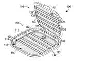
- FIG. 1Ais a schematic perspective view of an exemplary microwave heating apparatus, in a partially open configuration
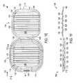
- FIG. 1Bis a schematic perspective view of the microwave heating apparatus of FIG. 1A , in a closed configuration
- FIG. 1Cis a schematic end view of the microwave heating apparatus of FIG. 1B , viewed along a line 1 C- 1 C;
- FIG. 1Dis a schematic cross-sectional view of the microwave heating apparatus of FIG. 1B , taken along a line 1 D- 1 D;
- FIG. 1Eis a schematic top plan view of the microwave heating apparatus of FIG. 1A , in a fully open configuration
- FIG. 1Fis a schematic cross-sectional view of the microwave heating apparatus of FIG. 1E , taken along a line 1 F- 1 F.
- the tray 102generally includes a base 110 and a wall 112 extending upwardly from a peripheral margin of the base 110 . All or a portion of the wall 112 may have a sloped profile, as shown in FIGS. 1D and 1F , an upright profile, or any other suitable profile. A rim or flange 114 may extend around an uppermost margin of the wall 112 . The wall 112 and/or flange 114 may be constructed to provide dimensional stability to the apparatus 100 .
- the base 110generally includes a central portion 116 circumscribed by a peripheral portion 118 .
- the peripheral portion 118may have a slightly curved profile when viewed in cross-section, as shown in FIGS. 1D and 1F , or may have any other suitable profile.
- the central portion 116includes a plurality of substantially planar surfaces or portions 120 that may be somewhat raised or elevated relative to the peripheral portion 118 , such that the peripheral portion 118 defines a lowermost portion of the tray 102 ( FIG. 1D ).
- a plurality of elongated indentations, recesses, or channels 122extend in a direction D 1 (transverse to a direction D 2 ) across the central portion 116 of the base 110 between the planar portions 120 to provide venting of moisture generated by the food item ( FIG.
- the channels 122generally recede in a downward direction towards the lowermost part of the base 110 , in this instance, the peripheral portion 118 . In the illustrated embodiment, the channels 122 do not extend as far downwardly as the lowermost point of the peripheral portion 118 . However, it is understood that the channels 122 may have any suitable depth and may extend to the depth of the peripheral portion 118 if desired.
- the cover 104may include a central portion 124 including a plurality of substantially planar surfaces or portions 126 , and a plurality of elongated indentations, recesses, or channels 128 extending in a direction D 1 (transverse to a direction D 2 ) across the central portion 124 between, and receding from, the planar portions 126 .
- the cover 104also may include a rim 130 that circumscribes the central portion 124 and generally defines at least a portion of a peripheral margin of the cover 104 .
- the rim 130When viewed in a fully open condition ( FIGS. 1E and 1F ), the rim 130 may define the lowermost portion of the cover 104 , and the central portion 124 may be somewhat elevated relative to the rim 130 .
- the channels 128do not extend as far downwardly as the lowermost point of the rim 130 .
- the channels 128may have any suitable depth and may extend to the depth of the rim 130 if desired.
- the rim 130may define an uppermost portion of the cover 104 and the planar portion 126 of the cover 104 may define a lowermost portion of the cover 104 .
- the central portion 124 of the cover 104may extend at least partially into the interior of the tray 102 when the cover 104 is in the closed position, as shown schematically in FIG. 1D .
- the covermay be generally planar with a plurality of channels receding away from the planar surface, such that the central portion and the rim are substantially coplanar (i.e., the rim and the planar surface lie within substantially the same horizontal plane).
- the covermay be sized and/or dimensioned to extend into the interior of the tray if desired, or may be dimensioned to be in face-to-face contact with the rim 114 of the tray 102 .
- the respective channels 122 , 128are substantially in register with one another ( FIG. 1D ), with the respective channels 122 , 128 in the base 110 and cover 104 receding away from one another.
- the channels 122 , 128may be out of register (i.e., not aligned) with one another.
- the base 110 and cover 104each include four channels 122 , 128 that are substantially parallel to one another, each channel 122 , 128 having a substantially arcuate profile (e.g., curved or semi-circular) when viewed in cross-section ( FIGS. 1D and 1F ).
- a substantially arcuate profilee.g., curved or semi-circular
- FIGS. 1D and 1Fany number, arrangement, and shape of channels 122 , 128 may be used, as needed to provide the desired degree of venting for the particular heating application.
- one or more microwave energy interactive elements 132 , 134may overlie at least a portion of the substantially planar portions 120 , 126 of the tray 102 and/or cover 104 , such that the planar portions 120 , 126 serve as respective heating areas or surfaces 120 , 126 .
- the elementsmay be susceptors, which generally comprise a thin layer of microwave energy interactive material (generally less than about 100 angstroms in thickness, for example, from about 60 to about 100 angstroms in thickness) that tends to absorb at least a portion of impinging microwave energy and convert it to thermal energy (i.e., heat) at the interface with the food item.
- Susceptorsoften are used to promote browning and/or crisping of the surface of a food item. However, other microwave energy interactive elements may be used.
- the susceptors 132 , 134may be supported on a polymer film, which generally may define respective food-contacting surfaces 134 , 136 of the tray 102 and cover 104 . In the illustrated example, the susceptors 134 , 136 only overlie the substantially planar surfaces 120 , 126 of the tray 102 and cover 104 .
- the susceptormay overlie any other part of the tray 102 or cover 104 , for example, any part intended to be in close proximity to the food item (e.g., channels 122 , 128 , the peripheral portion 118 of the base 110 and/or the wall 112 of the tray 102 ).
- the apparatus 100may include a locking mechanism to releasably secure the cover 104 in a closed, superposed relationship with the tray 102 .
- the locking mechanismincludes a tab 140 adapted to be received in a slot 142 ( FIG. 1E ) in the wall 112 of the tray 102 .
- the tab 140 and the slot 142are in respective portions of the cover 104 and tray 102 distal from the separator panel 108 . If desired, the positions of the tab and slot could be interchanged, such that the slot in is in the cover and the tab extends from the tray.
- a food item(not shown) may be placed on the central portion 116 of the tray 102 .
- the apparatus 100may be closed by pivoting the cover 104 toward the tray 102 until the cover 102 is in a superposed relationship with the tray 102 .
- the respective planar portions (i.e., the respective heating surfaces) 120 , 126 of the tray 102 and cover 104at least partially engage opposite surfaces of the food item.
- the cover 104then may be locked in the closed position by inserting the tab 140 into the slot 142 , as shown in FIGS. 1B and 1C .
- FIGS. 1B-1Dare representative of the closed apparatus 100 in an empty condition or containing a relatively thin food item.
- a food item having a greater thicknessmay cause the tray 102 and cover 104 to be more distant from one another in the closed configuration.
- some downward forcemay need to be exerted on the food item and/or tray 102 to insert the tab 140 into the slot 142 .
- the cover 104may remain urged toward the food item during the heating cycle, which may enhance heating, browning, and/or crisping further.
- the susceptors 132 , 134convert at least a portion of the impinging microwave energy to thermal energy (i.e., sensible heat), which then may be transferred to the adjacent surface of the food item to enhance browning and/or crisping of the affected areas. At least some of any steam released from the food item may be carried away from the food item along the channels 122 , 128 , which serve as venting channels, thereby further enhancing browning and/or crisping. Additionally, the elevated central portion 116 of the tray 102 maintains the food item in an elevated position, which reduces the amount of sensible heat transferred from the susceptor 132 on the tray 102 to the ambient environment of the microwave oven, still further enhancing the browning and/or crisping of the food item.
- thermal energyi.e., sensible heat
- the pattern of browning and/or crispingmay include an overall darkened appearance with somewhat lighter areas corresponding to the areas overlying channels 122 , 128 , generally resembling the visual appearance of grill marks.
- the apparatus 100 of the present disclosuremay be formed from materials having sufficient strength and/or rigidity to minimize any structural change or deformation.
- the wall 112 of the tray 102 , the locking mechanism (e.g., tab 140 and slot 142 ), and other components of the apparatus 100may provide further structural stability, and therefore resistance to warping, during heating, so that the susceptors 132 , 134 substantially remain in the desired position relative to the surfaces of the food item to attain the desired degree of heating, browning, and crisping of the food item.
- any of such apparatuseshave any suitable shape and dimensions, depending on the type of food item being heated, the desired heating time, the desired degree of browning and/or crisping, or any other suitable criteria.
- the central portions 116 , 124 of the base 110 and cover 104are substantially square in shape with rounded corners
- the peripheral portion 118 of the tray 102is substantially square annular in shape with rounded corners.
- any of the various parts of the apparatus 100may have any suitable shape, for example, circular, square, triangular, or any other regular or irregular shape, as needed or desired for a given heating application.
- the base 110 and/or cover 104 and/or the respective heating surfaces 120 , 126may be contoured to accommodate the shape of a food item having a shaped or irregular surface, for example, a domed or bowed surface. In doing so, the microwave energy interactive elements may be brought into closer proximity with the surface of the food item.
- contoured surfacesNumerous examples of contoured surfaces that may be suitable for use with the present invention are provided in U.S. Patent Application Publication No. 2008/0164178 A1, published Jul. 10, 2008, and U.S. Patent Application Publication No. 2008/0000896 A1, published Jan. 3, 2008, both of which are incorporated by reference herein in their entirety. In some instances, such contoured surfaces may cooperate with one or more venting channels and/or microwave transparent areas to create the visual appearance of grill marks.
- any of the apparatuses according to the disclosuremay be formed from various materials, provided that the materials are substantially resistant to softening, scorching, combusting, or degrading at typical microwave oven heating temperatures, for example, at from about 250° F. to about 425° F.
- the materialsmay include microwave energy interactive materials, for example, those used to form susceptors and other microwave energy interactive elements, and microwave energy transparent or inactive materials, for example, those used to form the remainder of the apparatus.
- the microwave energy interactive materialmay be an electroconductive or semiconductive material, for example, a metal or a metal alloy provided as a metal foil; a vacuum deposited metal or metal alloy; or a metallic ink, an organic ink, an inorganic ink, a metallic paste, an organic paste, an inorganic paste, or any combination thereof.
- metals and metal alloysthat may be suitable include, but are not limited to, aluminum, chromium, copper, inconel alloys (nickel-chromium-molybdenum alloy with niobium), iron, magnesium, nickel, stainless steel, tin, titanium, tungsten, and any combination or alloy thereof.
- the microwave energy interactive materialmay comprise a metal oxide, for example, oxides of aluminum, iron, and tin, optionally used in conjunction with an electrically conductive material.
- a metal oxidefor example, oxides of aluminum, iron, and tin
- ITOindium tin oxide
- the microwave energy interactive materialmay comprise a suitable electroconductive, semiconductive, or non-conductive artificial dielectric or ferroelectric.
- Artificial dielectricscomprise conductive, subdivided material in a polymeric or other suitable matrix or binder, and may include flakes of an electroconductive metal, for example, aluminum.
- the apparatusalternatively or additionally may include a foil or high optical density evaporated material having a thickness sufficient to reflect a substantial portion of impinging microwave energy.
- a foil or high optical density evaporated materialhaving a thickness sufficient to reflect a substantial portion of impinging microwave energy.
- Such elementsare typically formed from a conductive, reflective metal or metal alloy, for example, aluminum, copper, or stainless steel, in the form of a solid “patch” generally having a thickness of from about 0.000285 inches to about 0.05 inches, for example, from about 0.0003 inches to about 0.03 inches. Other such elements may have a thickness of from about 0.00035 inches to about 0.020 inches, for example, 0.016 inches.
- microwave energy reflecting elementsmay be used where the food item is prone to scorching or drying out during heating. Smaller microwave energy reflecting elements may be used to diffuse or lessen the intensity of microwave energy. A plurality of smaller microwave energy reflecting elements also may be arranged to form a microwave energy directing element to direct microwave energy to specific areas of the food item. If desired, the loops may be of a length that causes microwave energy to resonate, thereby enhancing the distribution effect.
- Microwave energy distributing elementsare described in U.S. Pat. Nos. 6,204,492, 6,433,322, 6,552,315, and 6,677,563, each of which is incorporated by reference in its entirety.
- any of the numerous microwave energy interactive elements described herein or contemplated herebymay be substantially continuous, that is, without substantial breaks or interruptions, or may be discontinuous, for example, by including one or more breaks or apertures that transmit microwave energy therethrough.
- the breaks or aperturesmay be sized and positioned to heat particular areas of the food item selectively.
- the breaks or aperturesmay extend through the entire structure, or only through one or more layers.
- the number, shape, size, and positioning of such breaks or aperturesmay vary for a particular application depending on the type of construct being formed, the food item to be heated therein or thereon, the desired degree of shielding, browning, and/or crisping, whether direct exposure to microwave energy is needed or desired to attain uniform heating of the food item, the need for regulating the change in temperature of the food item through direct heating, and whether and to what extent there is a need for venting.
- the aperturemay be a physical aperture or void in one or more layers or materials used to form the construct, or may be a non-physical “aperture”.
- a non-physical apertureis a microwave energy transparent area that allows microwave energy to pass through the structure without an actual void or hole cut through the structure. Such areas may be formed by simply not applying a microwave energy interactive material to the particular area, or by removing microwave energy interactive material in the particular area, or by chemically and/or mechanically deactivating the microwave energy interactive material in the particular area. While both physical and non-physical apertures allow the food item to be heated directly by the microwave energy, a physical aperture also provides a venting function to allow steam or other vapors to escape from the interior of the construct.
- the arrangement of microwave energy interactive and microwave energy transparent areasmay be selected to provide various levels of heating, as needed or desired for a particular application. For example, where greater heating is desired, the total inactive area may be increased. In doing so, more microwave energy is transmitted to the food item. Alternatively, by decreasing the total inactive area, more microwave energy is absorbed by the microwave energy interactive areas, converted into thermal energy, and transmitted to the surface of the food item to enhance browning and/or crisping.
- one or more panels, portions of panels, or portions of the constructmay be designed to be microwave energy transparent to ensure that the microwave energy is focused efficiently on the areas to be browned and/or crisped, rather than being lost to portions of the food item not intended to be browned and/or crisped or to the heating environment.
- Thismay be achieved using any suitable technique, such as those described above.
- the channels 122 , 128 , wall 112 , and various other portions of the apparatus 110may be designed to be microwave energy transparent if such areas are not intended to be in intimate and/or proximate contact with the surface of the food item.
- the microwave energy interactive elementmay be supported on a microwave inactive or transparent substrate, for example, a polymer film or other suitable polymeric material, for ease of handling and/or to prevent contact between the microwave energy interactive material and the food item.
- a polymer film or other suitable polymeric materialfor ease of handling and/or to prevent contact between the microwave energy interactive material and the food item.
- polymer filmsthat may be suitable include, but are not limited to, polyolefins, polyesters, polyamides, polyimides, polysulfones, polyether ketones, cellophanes, or any combination thereof.
- the polymer filmcomprises polyethylene terephthalate.
- the thickness of the filmgenerally may be from about 35 gauge to about 10 mil. In each of various examples, the thickness of the film may be from about 40 to about 80 gauge, from about 45 to about 50 gauge, about 48 gauge, or any other suitable thickness.
- Other non-conducting substrate materialssuch as paper and paper laminates, metal oxides, silicates, cellulosics, or any combination
- the microwave energy interactive materialmay be applied to the substrate in any suitable manner, and in some instances, the microwave energy interactive material is printed on, extruded onto, sputtered onto, evaporated on, or laminated to the substrate.
- the microwave energy interactive materialmay be applied to the substrate in any pattern, and using any technique, to achieve the desired heating effect of the food item.
- the microwave energy interactive materialmay be provided as a continuous or discontinuous layer or coating including circles, loops, hexagons, islands, squares, rectangles, octagons, and so forth.
- the apparatusmay be formed at least partially from a polymer or polymeric material.
- all or a portion the apparatusmay be formed from a paper or paperboard material.
- the paperhas a basis weight of from about 15 to about 60 lbs/ream (lb/3000 sq. ft.), for example, from about 20 to about 40 lbs/ream.
- the paperhas a basis weight of about 25 lbs/ream.
- the paperboardhaving a basis weight of from about 60 to about 330 lbs/ream, for example, from about 80 to about 140 lbs/ream.
- the paperboardgenerally may have a thickness of from about 6 to about 30 mils, for example, from about 12 to about 28 mils. In one particular example, the paperboard has a thickness of about 12 mils.
- Any suitable paperboardmay be used, for example, a solid bleached or solid unbleached sulfate board, such as SUS® board, commercially available from Graphic Packaging International.
- the apparatusmay be formed according to numerous processes known to those in the art, including using adhesive bonding, thermal bonding, ultrasonic bonding, mechanical stitching, or any other suitable process. Any of the various components used to form the apparatus may be provided as a sheet of material, a roll of material, or a die cut material in the shape of the apparatus to be formed (e.g., a blank).
- the tray 102 and/or cover 104each may be formed using a thermal, mechanical, or thermomechanical pressing technique.
- the exterior side of the cover 104may have a plurality of protrusions 144 corresponding to the channels or indentations 128 on the interior side of the cover 104 , as shown in FIG. 1B .
- the tray 102may similarly include a plurality of protrusions (not shown) on an exterior side of the base 110 opposite the channels or indentations 122 .
- the exterior side of the tray 102 and/or cover 104may be substantially planar and/or may be provided with indentations or channels on the respective interior side in some other suitable manner.
Landscapes
- Engineering & Computer Science (AREA)
- Food Science & Technology (AREA)
- Physics & Mathematics (AREA)
- Electromagnetism (AREA)
- Life Sciences & Earth Sciences (AREA)
- Mechanical Engineering (AREA)
- Cookers (AREA)
- Electric Ovens (AREA)
- Baking, Grill, Roasting (AREA)
Abstract
Description
Claims (19)
Priority Applications (2)
| Application Number | Priority Date | Filing Date | Title |
|---|---|---|---|
| US12/378,574US8872079B2 (en) | 2008-02-18 | 2009-02-17 | Apparatus for preparing a food item in a microwave oven |
| US14/450,731US10351329B2 (en) | 2008-02-18 | 2014-08-04 | Apparatus for preparing a food item in a microwave oven |
Applications Claiming Priority (2)
| Application Number | Priority Date | Filing Date | Title |
|---|---|---|---|
| US2947008P | 2008-02-18 | 2008-02-18 | |
| US12/378,574US8872079B2 (en) | 2008-02-18 | 2009-02-17 | Apparatus for preparing a food item in a microwave oven |
Related Child Applications (1)
| Application Number | Title | Priority Date | Filing Date |
|---|---|---|---|
| US14/450,731DivisionUS10351329B2 (en) | 2008-02-18 | 2014-08-04 | Apparatus for preparing a food item in a microwave oven |
Publications (2)
| Publication Number | Publication Date |
|---|---|
| US20090206075A1 US20090206075A1 (en) | 2009-08-20 |
| US8872079B2true US8872079B2 (en) | 2014-10-28 |
Family
ID=40954159
Family Applications (2)
| Application Number | Title | Priority Date | Filing Date |
|---|---|---|---|
| US12/378,574Active2031-12-11US8872079B2 (en) | 2008-02-18 | 2009-02-17 | Apparatus for preparing a food item in a microwave oven |
| US14/450,731Active2030-02-25US10351329B2 (en) | 2008-02-18 | 2014-08-04 | Apparatus for preparing a food item in a microwave oven |
Family Applications After (1)
| Application Number | Title | Priority Date | Filing Date |
|---|---|---|---|
| US14/450,731Active2030-02-25US10351329B2 (en) | 2008-02-18 | 2014-08-04 | Apparatus for preparing a food item in a microwave oven |
Country Status (5)
| Country | Link |
|---|---|
| US (2) | US8872079B2 (en) |
| EP (1) | EP2245376B1 (en) |
| CA (1) | CA2715627C (en) |
| ES (1) | ES2523716T3 (en) |
| WO (1) | WO2009105398A2 (en) |
Cited By (1)
| Publication number | Priority date | Publication date | Assignee | Title |
|---|---|---|---|---|
| US11382459B2 (en)* | 2015-12-22 | 2022-07-12 | Tuesday Morning Partners, Ltd. | Cookware lid with basting projections |
Families Citing this family (22)
| Publication number | Priority date | Publication date | Assignee | Title |
|---|---|---|---|---|
| US8680448B2 (en) | 2006-05-15 | 2014-03-25 | Graphic Packaging International, Inc. | Microwavable construct with contoured heating surface |
| US8803050B2 (en) | 2006-05-15 | 2014-08-12 | Graphic Packaging International, Inc. | Microwavable construct with contoured heating surface |
| EP2245376B1 (en) | 2008-02-18 | 2014-10-15 | Graphic Packaging International, Inc. | Apparatus for preparing a food item in a micowave oven |
| WO2009105397A2 (en) | 2008-02-18 | 2009-08-27 | Graphic Packaging International, Inc. | Apparatus for cooking raw food items in a microwave oven |
| DE102008035235B4 (en)* | 2008-07-29 | 2014-05-22 | Ivoclar Vivadent Ag | Device for heating molded parts, in particular dental ceramic molded parts |
| US8395101B2 (en) | 2009-05-01 | 2013-03-12 | Graphic Packaging International, Inc. | Construct with locating feature |
| JP6290370B2 (en) | 2013-03-15 | 2018-03-07 | グラフィック パッケージング インターナショナル インコーポレイテッドGraphic Packaging International,Inc. | Container with heating shape |
| CN104515166A (en)* | 2013-09-30 | 2015-04-15 | 广东美的厨房电器制造有限公司 | Microwave oven and baking pan assembly thereof |
| DE202013105686U1 (en) | 2013-12-13 | 2015-03-17 | Rational Ag | Food support and grill accessories |
| US10813495B2 (en) | 2013-12-13 | 2020-10-27 | Rational Aktiengesellschaft | Grilling accessory and grilling system |
| EP3083227B1 (en) | 2013-12-16 | 2018-10-31 | Graphic Packaging International, LLC | Construct with stiffening features |
| CN105830532A (en)* | 2014-01-14 | 2016-08-03 | 伊莱克斯家用电器股份公司 | Wire Mesh Trays for Microwave or Microwave Cooking Appliances |
| WO2016077973A1 (en)* | 2014-11-18 | 2016-05-26 | 何素华 | Baking pan assembly of microwave oven |
| WO2016192971A1 (en) | 2015-06-02 | 2016-12-08 | Arcelik Anonim Sirketi | A microwave oven with increased cooking efficiency |
| CN205037382U (en)* | 2015-09-14 | 2016-02-17 | 佛山市顺德区汉蒲电器科技有限公司 | Removable microwave ovenware of modified |
| USD819391S1 (en)* | 2016-12-03 | 2018-06-05 | Helen Of Troy Limited | Microwave bacon tray |
| US10708986B2 (en)* | 2018-05-01 | 2020-07-07 | Dart Industries Inc. | Device for and method of microwave heating with inversion |
| CN110089956B (en)* | 2019-04-11 | 2022-05-17 | 慈溪市艾肯电器有限公司 | Sandwich machine |
| CN110123161B (en)* | 2019-04-11 | 2022-05-13 | 慈溪市艾肯电器有限公司 | Sandwich machine with adjustable slicing distance |
| CN110687136B (en)* | 2019-09-11 | 2022-04-08 | 河南工业大学 | Wheat moisture microwave transmission model construction method based on COMSOL |
| JP2024546689A (en) | 2021-12-10 | 2024-12-26 | グラフィック パッケージング インターナショナル エルエルシー | Packaging Materials |
| DE202022101343U1 (en) | 2022-03-11 | 2023-09-05 | Gpi Frankfurt & Augsburg Gmbh | Skin packaging |
Citations (94)
| Publication number | Priority date | Publication date | Assignee | Title |
|---|---|---|---|---|
| US2859122A (en) | 1955-10-06 | 1958-11-04 | American Cyanamid Co | Meat package |
| US3965323A (en) | 1975-02-26 | 1976-06-22 | Corning Glass Works | Method and apparatus for providing uniform surface browning of foodstuff through microwave energy |
| DE7903283U1 (en) | 1979-02-07 | 1979-05-10 | Delbrouck Franz Gmbh | Plastic fruit baskets |
| US4175483A (en) | 1978-05-18 | 1979-11-27 | Mcgraw-Edison Company | Donut maker appliance with improved means for coating batter with cooking oil |
| EP0007522A1 (en) | 1978-07-13 | 1980-02-06 | Schott Glaswerke | Supporting grill for food to be baked, roasted or broiled |
| US4606496A (en) | 1984-03-20 | 1986-08-19 | James River Corporation Of Virginia | Rigid paperboard container |
| US4609140A (en) | 1982-04-13 | 1986-09-02 | James River - Dixie Northern Inc. | Rigid paperboard container and method and apparatus for producing same |
| EP0246041A2 (en) | 1986-05-09 | 1987-11-19 | Alcan International Limited | Microwave container |
| US4721500A (en) | 1982-04-13 | 1988-01-26 | James River-Dixie Northern, Inc. | Method of forming a rigid paper-board container |
| US4721499A (en) | 1984-03-20 | 1988-01-26 | James River Corporation Of Virginia | Method of producing a rigid paperboard container |
| US4775771A (en) | 1987-07-30 | 1988-10-04 | James River Corporation | Sleeve for crisping and browning of foods in a microwave oven and package and method utilizing same |
| US4777053A (en) | 1986-06-02 | 1988-10-11 | General Mills, Inc. | Microwave heating package |
| US4794005A (en) | 1986-02-14 | 1988-12-27 | James River Corporation | Package assembly including a multi-surface, microwave interactive tray |
| US4832676A (en) | 1986-12-08 | 1989-05-23 | James River-Norwalk, Inc. | Method and apparatus for forming paperboard containers |
| US4862791A (en)* | 1987-07-31 | 1989-09-05 | Baughey Nancy C | Microwave frying system |
| US4866234A (en) | 1985-06-25 | 1989-09-12 | Alcan International Limited | Microwave container and method of making same |
| US4865921A (en) | 1987-03-10 | 1989-09-12 | James Riker Corporation Of Virginia | Microwave interactive laminate |
| US4870233A (en) | 1988-09-19 | 1989-09-26 | General Mills, Inc. | Metal tray and susceptor combination for use in microwave ovens |
| US4888459A (en) | 1986-12-18 | 1989-12-19 | Alcan International Limited | Microwave container with dielectric structure of varying properties and method of using same |
| US4890439A (en) | 1988-11-09 | 1990-01-02 | James River Corporation | Flexible disposable material for forming a food container for microwave cooking |
| US4916280A (en) | 1987-07-11 | 1990-04-10 | Nestec S.A. | Food package adapted particularly for microwave heating |
| US4936935A (en) | 1988-05-20 | 1990-06-26 | Beckett Industries Inc. | Microwave heating material |
| EP0382399A2 (en) | 1989-02-09 | 1990-08-16 | Alcan International Limited | Methods and devices used in the microwave heating of foods and other materials |
| US5026958A (en) | 1990-01-22 | 1991-06-25 | Urania Palacios | Cooking container or like assembly for the cooking of food utilizing a microwave oven |
| US5039364A (en) | 1988-11-28 | 1991-08-13 | Beckett Industries Inc. | Method of making selective microwave heating material |
| US5117078A (en) | 1990-02-02 | 1992-05-26 | Beckett Industries Inc. | Controlled heating of foodstuffs by microwave energy |
| AU635667B2 (en) | 1991-01-29 | 1993-03-25 | Amcor Limited | A container |
| US5213902A (en) | 1991-02-19 | 1993-05-25 | Beckett Industries Inc. | Microwave oven package |
| US5217768A (en) | 1991-09-05 | 1993-06-08 | Advanced Dielectric Technologies | Adhesiveless susceptor films and packaging structures |
| US5221419A (en) | 1991-02-19 | 1993-06-22 | Beckett Industries Inc. | Method for forming laminate for microwave oven package |
| US5260537A (en) | 1991-06-17 | 1993-11-09 | Beckett Industries Inc. | Microwave heating structure |
| WO1993023971A1 (en) | 1992-05-21 | 1993-11-25 | Campbell Soup Company | Metal container and use thereof in a microwave oven |
| US5266386A (en) | 1991-02-14 | 1993-11-30 | Beckett Industries Inc. | Demetallizing procedure |
| US5298708A (en)* | 1991-02-07 | 1994-03-29 | Minnesota Mining And Manufacturing Company | Microwave-active tape having a cured polyolefin pressure-sensitive adhesive layer |
| US5310980A (en) | 1988-11-28 | 1994-05-10 | Beckett Industries, Inc. | Control of microwave energy in cooking foodstuffs |
| US5310977A (en) | 1989-02-03 | 1994-05-10 | Minnesota Mining And Manufacturing Company | Configured microwave susceptor |
| US5317118A (en) | 1992-02-05 | 1994-05-31 | Golden Valley Microwave Foods Inc. | Package with microwave induced insulation chambers |
| USRE34683E (en) | 1987-03-10 | 1994-08-02 | James River Corporation Of Virginia | Control of microwave interactive heating by patterned deactivation |
| US5340436A (en) | 1991-02-14 | 1994-08-23 | Beckett Industries Inc. | Demetallizing procedure |
| US5350904A (en) | 1988-05-23 | 1994-09-27 | The Pillsbury Company | Susceptors having disrupted regions for differential heating in a microwave oven |
| US5354973A (en) | 1992-01-29 | 1994-10-11 | Beckett Industries Inc. | Microwave heating structure comprising an array of shaped elements |
| US5410135A (en) | 1988-09-01 | 1995-04-25 | James River Paper Company, Inc. | Self limiting microwave heaters |
| US5424517A (en) | 1993-10-27 | 1995-06-13 | James River Paper Company, Inc. | Microwave impedance matching film for microwave cooking |
| JPH0733228U (en) | 1993-12-01 | 1995-06-20 | 東洋アルミホイルプロダクツ株式会社 | Range grill mat |
| WO1995024110A2 (en) | 1994-03-04 | 1995-09-08 | Gics & Vermee, L.P. | Ovenable food package |
| US5519195A (en) | 1989-02-09 | 1996-05-21 | Beckett Technologies Corp. | Methods and devices used in the microwave heating of foods and other materials |
| WO1996022228A2 (en) | 1995-01-21 | 1996-07-25 | Novus Foods Ltd. | Microwave oven food container |
| US5565228A (en) | 1995-05-02 | 1996-10-15 | Gics & Vermee, L.P. | Ovenable food product tray and an ovenable food product package |
| US5585027A (en) | 1994-06-10 | 1996-12-17 | Young; Robert C. | Microwave susceptive reheating support with perforations enabling change of size and/or shape of the substrate |
| US5628921A (en) | 1991-02-14 | 1997-05-13 | Beckett Technologies Corp. | Demetallizing procedure |
| US5698127A (en) | 1995-09-18 | 1997-12-16 | Lai; Lawrence | Microwavable container with heating element having energy collecting loops |
| US5759422A (en) | 1996-02-14 | 1998-06-02 | Fort James Corporation | Patterned metal foil laminate and method for making same |
| US5800724A (en) | 1996-02-14 | 1998-09-01 | Fort James Corporation | Patterned metal foil laminate and method for making same |
| US6114679A (en) | 1997-01-29 | 2000-09-05 | Graphic Packaging Corporation | Microwave oven heating element having broken loops |
| US6150646A (en) | 1996-08-26 | 2000-11-21 | Graphic Packaging Corporation | Microwavable container having active microwave energy heating elements for combined bulk and surface heating |
| US6150647A (en) | 1999-06-18 | 2000-11-21 | The Procter & Gamble Company | Flexible, cushioned, high surface area food storage and preparation bags |
| US6204492B1 (en) | 1999-09-20 | 2001-03-20 | Graphic Packaging Corporation | Abuse-tolerant metallic packaging materials for microwave cooking |
| US20010000732A1 (en) | 1998-07-31 | 2001-05-03 | Steamway Franchise Sales, Inc. | Microwave steaming tray |
| US6251451B1 (en) | 1996-08-26 | 2001-06-26 | Graphic Packaging Corporation | Microwavable package |
| US6414290B1 (en) | 1998-03-19 | 2002-07-02 | Graphic Packaging Corporation | Patterned microwave susceptor |
| US6415944B1 (en) | 1998-08-27 | 2002-07-09 | The Procter & Gamble Company | Articulable container |
| US6433322B2 (en) | 1999-09-20 | 2002-08-13 | Graphic Packaging Corporation | Abuse-tolerant metallic packaging materials for microwave cooking |
| US6463844B1 (en) | 2000-08-04 | 2002-10-15 | Testrite Baparoma International, Llc | Baking pan |
| US6501059B1 (en)* | 1999-09-27 | 2002-12-31 | Roy Lee Mast | Heavy-metal microwave formations and methods |
| JP2003095332A (en) | 2001-09-25 | 2003-04-03 | Masako Ishiguro | Boiled-rice storage container |
| US20030085224A1 (en) | 2001-11-07 | 2003-05-08 | Tsontzidis Sandra M. | Microwave packaging with indentation patterns |
| JP2003165582A (en) | 2001-11-28 | 2003-06-10 | Snow Brand Milk Prod Co Ltd | Tray for use in microwave oven and food package using the same |
| US6608292B1 (en)* | 2002-07-26 | 2003-08-19 | Neal Patrick Barnes | Microwave grilling appliance |
| US6639199B1 (en) | 2001-07-10 | 2003-10-28 | Samuel R. Ross, Jr. | Seafood microwave cooker |
| US6651874B1 (en) | 1998-09-15 | 2003-11-25 | Steen Pedersen | Packing tray and method for its production and use |
| US6677563B2 (en) | 2001-12-14 | 2004-01-13 | Graphic Packaging Corporation | Abuse-tolerant metallic pattern arrays for microwave packaging materials |
| WO2004020310A1 (en) | 2002-08-27 | 2004-03-11 | Christopher Paul Wedlock | Microwave dispersing device |
| US6717121B2 (en) | 2001-09-28 | 2004-04-06 | Graphic Packaging International, Inc. | Patterned microwave susceptor element and microwave container incorporating same |
| KR100436263B1 (en) | 2002-03-26 | 2004-06-16 | 삼성전자주식회사 | Cooking Container and Microwave Oven Having the Cooking Container |
| US20040216730A1 (en) | 2003-04-10 | 2004-11-04 | Sawhney Ravi K. | Portable cooking appliance |
| GB2407153A (en) | 2003-10-18 | 2005-04-20 | Stephen Graham Rutherford | A tray and/or waveguide cap for a forced air/microwave combination oven |
| WO2005085091A2 (en) | 2004-03-01 | 2005-09-15 | Kraftfoods Holdings, Inc. | Multi-purpose food preparation kit |
| US20050205565A1 (en) | 2004-02-09 | 2005-09-22 | Cole Lorin R | Microwave cooking packages and methods of making thereof |
| US20060011620A1 (en) | 2001-11-07 | 2006-01-19 | Graphic Packaging International, Inc. | Microwave packaging with indentation patterns |
| US6988654B2 (en) | 2001-01-18 | 2006-01-24 | Graphic Packaging International, Inc. | Container with improved stacking/denesting capability |
| US7019271B2 (en) | 2002-02-08 | 2006-03-28 | Graphic Packaging International, Inc. | Insulating microwave interactive packaging |
| US20070029316A1 (en)* | 2006-06-01 | 2007-02-08 | Products Of Tomorrow, Inc. | Microwavable grill |
| US20070221666A1 (en) | 2006-03-09 | 2007-09-27 | Keefe Daniel J | Susceptor with apertured support |
| WO2007133767A2 (en) | 2006-05-15 | 2007-11-22 | Graphic Packaging International, Inc. | Microwavable construct with contoured heating surface |
| JP2007312819A (en) | 2006-05-23 | 2007-12-06 | Toppan Printing Co Ltd | Induction heating cooking container |
| US20080000896A1 (en)* | 2006-05-15 | 2008-01-03 | Lafferty Terrence P | Microwavable construct with contoured heating surface |
| US7323669B2 (en) | 2002-02-08 | 2008-01-29 | Graphic Packaging International, Inc. | Microwave interactive flexible packaging |
| KR100813904B1 (en) | 2007-02-21 | 2008-03-17 | 정대진 | Grilled Eel |
| US20080164178A1 (en) | 2006-05-15 | 2008-07-10 | Wnek Patrick H | Microwavable construct with contoured heating surface |
| WO2008144343A2 (en) | 2007-05-15 | 2008-11-27 | Graphic Packaging International, Inc. | Microwavable construct with contoured heating surface |
| US7476830B2 (en) | 2005-05-25 | 2009-01-13 | Graphic Packaging International, Inc. | Microwave packaging for multicomponent meals |
| US20090206074A1 (en) | 2008-02-18 | 2009-08-20 | Schneider Lee M | Apparatus for Cooking Raw Food Items in a Microwave Oven |
| WO2009105398A2 (en) | 2008-02-18 | 2009-08-27 | Graphic Packaging International, Inc. | Apparatus for preparing a food item in a micowave oven |
| WO2010127214A2 (en) | 2009-05-01 | 2010-11-04 | Graphic Packaging International, Inc. | Construct with locating feature |
Family Cites Families (2)
| Publication number | Priority date | Publication date | Assignee | Title |
|---|---|---|---|---|
| US7893388B2 (en)* | 2007-01-12 | 2011-02-22 | Barnes Neal P | Microwave grill |
| JP6094817B2 (en) | 2013-11-11 | 2017-03-15 | トヨタ自動車株式会社 | Method for producing non-aqueous electrolyte secondary battery |
- 2009
- 2009-02-16EPEP09712150.3Apatent/EP2245376B1/enactiveActive
- 2009-02-16ESES09712150.3Tpatent/ES2523716T3/enactiveActive
- 2009-02-16WOPCT/US2009/034191patent/WO2009105398A2/enactiveApplication Filing
- 2009-02-16CACA2715627Apatent/CA2715627C/enactiveActive
- 2009-02-17USUS12/378,574patent/US8872079B2/enactiveActive
- 2014
- 2014-08-04USUS14/450,731patent/US10351329B2/enactiveActive
Patent Citations (116)
| Publication number | Priority date | Publication date | Assignee | Title |
|---|---|---|---|---|
| US2859122A (en) | 1955-10-06 | 1958-11-04 | American Cyanamid Co | Meat package |
| US3965323A (en) | 1975-02-26 | 1976-06-22 | Corning Glass Works | Method and apparatus for providing uniform surface browning of foodstuff through microwave energy |
| US4175483A (en) | 1978-05-18 | 1979-11-27 | Mcgraw-Edison Company | Donut maker appliance with improved means for coating batter with cooking oil |
| EP0007522A1 (en) | 1978-07-13 | 1980-02-06 | Schott Glaswerke | Supporting grill for food to be baked, roasted or broiled |
| DE7903283U1 (en) | 1979-02-07 | 1979-05-10 | Delbrouck Franz Gmbh | Plastic fruit baskets |
| US4721500A (en) | 1982-04-13 | 1988-01-26 | James River-Dixie Northern, Inc. | Method of forming a rigid paper-board container |
| US4609140C1 (en) | 1982-04-13 | 2002-04-16 | James River Corp | Rigid paperboard container and method and apparatus for producing same |
| US4609140A (en) | 1982-04-13 | 1986-09-02 | James River - Dixie Northern Inc. | Rigid paperboard container and method and apparatus for producing same |
| US4721499A (en) | 1984-03-20 | 1988-01-26 | James River Corporation Of Virginia | Method of producing a rigid paperboard container |
| US4721499C1 (en) | 1984-03-20 | 2002-06-04 | Fort James Corp | Method of producing a rigid paperboard container |
| US4606496A (en) | 1984-03-20 | 1986-08-19 | James River Corporation Of Virginia | Rigid paperboard container |
| US4606496C1 (en) | 1984-03-20 | 2002-04-09 | Fort James Corp | Rigid paperboard container |
| US4866234A (en) | 1985-06-25 | 1989-09-12 | Alcan International Limited | Microwave container and method of making same |
| US4794005A (en) | 1986-02-14 | 1988-12-27 | James River Corporation | Package assembly including a multi-surface, microwave interactive tray |
| JPS62293020A (en) | 1986-05-09 | 1987-12-19 | アルカン・インタ−ナショナル・リミテッド | Vessel for microwave |
| CA1279902C (en) | 1986-05-09 | 1991-02-05 | Alcan International Limited | Microwave container including higher order mode generation |
| US4831224A (en) | 1986-05-09 | 1989-05-16 | Alcan International Limited | Package of material for microwave heating including container with stepped structure |
| EP0246041A2 (en) | 1986-05-09 | 1987-11-19 | Alcan International Limited | Microwave container |
| US4777053A (en) | 1986-06-02 | 1988-10-11 | General Mills, Inc. | Microwave heating package |
| US4832676A (en) | 1986-12-08 | 1989-05-23 | James River-Norwalk, Inc. | Method and apparatus for forming paperboard containers |
| US4888459A (en) | 1986-12-18 | 1989-12-19 | Alcan International Limited | Microwave container with dielectric structure of varying properties and method of using same |
| US4865921A (en) | 1987-03-10 | 1989-09-12 | James Riker Corporation Of Virginia | Microwave interactive laminate |
| USRE34683E (en) | 1987-03-10 | 1994-08-02 | James River Corporation Of Virginia | Control of microwave interactive heating by patterned deactivation |
| US4916280A (en) | 1987-07-11 | 1990-04-10 | Nestec S.A. | Food package adapted particularly for microwave heating |
| US4775771A (en) | 1987-07-30 | 1988-10-04 | James River Corporation | Sleeve for crisping and browning of foods in a microwave oven and package and method utilizing same |
| US4862791A (en)* | 1987-07-31 | 1989-09-05 | Baughey Nancy C | Microwave frying system |
| US4936935A (en) | 1988-05-20 | 1990-06-26 | Beckett Industries Inc. | Microwave heating material |
| US4963424A (en) | 1988-05-20 | 1990-10-16 | Beckett Industries Inc. | Microwave heating material |
| US5350904A (en) | 1988-05-23 | 1994-09-27 | The Pillsbury Company | Susceptors having disrupted regions for differential heating in a microwave oven |
| US5410135A (en) | 1988-09-01 | 1995-04-25 | James River Paper Company, Inc. | Self limiting microwave heaters |
| US4870233A (en) | 1988-09-19 | 1989-09-26 | General Mills, Inc. | Metal tray and susceptor combination for use in microwave ovens |
| US4890439A (en) | 1988-11-09 | 1990-01-02 | James River Corporation | Flexible disposable material for forming a food container for microwave cooking |
| US5039364A (en) | 1988-11-28 | 1991-08-13 | Beckett Industries Inc. | Method of making selective microwave heating material |
| US5310980A (en) | 1988-11-28 | 1994-05-10 | Beckett Industries, Inc. | Control of microwave energy in cooking foodstuffs |
| US5310977A (en) | 1989-02-03 | 1994-05-10 | Minnesota Mining And Manufacturing Company | Configured microwave susceptor |
| US5519195A (en) | 1989-02-09 | 1996-05-21 | Beckett Technologies Corp. | Methods and devices used in the microwave heating of foods and other materials |
| EP0382399A2 (en) | 1989-02-09 | 1990-08-16 | Alcan International Limited | Methods and devices used in the microwave heating of foods and other materials |
| US5026958A (en) | 1990-01-22 | 1991-06-25 | Urania Palacios | Cooking container or like assembly for the cooking of food utilizing a microwave oven |
| US5117078A (en) | 1990-02-02 | 1992-05-26 | Beckett Industries Inc. | Controlled heating of foodstuffs by microwave energy |
| AU635667B2 (en) | 1991-01-29 | 1993-03-25 | Amcor Limited | A container |
| US5298708A (en)* | 1991-02-07 | 1994-03-29 | Minnesota Mining And Manufacturing Company | Microwave-active tape having a cured polyolefin pressure-sensitive adhesive layer |
| US5340436A (en) | 1991-02-14 | 1994-08-23 | Beckett Industries Inc. | Demetallizing procedure |
| US5266386A (en) | 1991-02-14 | 1993-11-30 | Beckett Industries Inc. | Demetallizing procedure |
| US5628921A (en) | 1991-02-14 | 1997-05-13 | Beckett Technologies Corp. | Demetallizing procedure |
| US5672407A (en) | 1991-02-14 | 1997-09-30 | Beckett Technologies Corp. | Structure with etchable metal |
| US5221419A (en) | 1991-02-19 | 1993-06-22 | Beckett Industries Inc. | Method for forming laminate for microwave oven package |
| US5213902A (en) | 1991-02-19 | 1993-05-25 | Beckett Industries Inc. | Microwave oven package |
| US5260537A (en) | 1991-06-17 | 1993-11-09 | Beckett Industries Inc. | Microwave heating structure |
| US5217768A (en) | 1991-09-05 | 1993-06-08 | Advanced Dielectric Technologies | Adhesiveless susceptor films and packaging structures |
| US5354973A (en) | 1992-01-29 | 1994-10-11 | Beckett Industries Inc. | Microwave heating structure comprising an array of shaped elements |
| US5317118A (en) | 1992-02-05 | 1994-05-31 | Golden Valley Microwave Foods Inc. | Package with microwave induced insulation chambers |
| WO1993023971A1 (en) | 1992-05-21 | 1993-11-25 | Campbell Soup Company | Metal container and use thereof in a microwave oven |
| US5424517A (en) | 1993-10-27 | 1995-06-13 | James River Paper Company, Inc. | Microwave impedance matching film for microwave cooking |
| JPH0733228U (en) | 1993-12-01 | 1995-06-20 | 東洋アルミホイルプロダクツ株式会社 | Range grill mat |
| WO1995024110A2 (en) | 1994-03-04 | 1995-09-08 | Gics & Vermee, L.P. | Ovenable food package |
| US5585027A (en) | 1994-06-10 | 1996-12-17 | Young; Robert C. | Microwave susceptive reheating support with perforations enabling change of size and/or shape of the substrate |
| WO1996022228A2 (en) | 1995-01-21 | 1996-07-25 | Novus Foods Ltd. | Microwave oven food container |
| US5565228A (en) | 1995-05-02 | 1996-10-15 | Gics & Vermee, L.P. | Ovenable food product tray and an ovenable food product package |
| US5698127A (en) | 1995-09-18 | 1997-12-16 | Lai; Lawrence | Microwavable container with heating element having energy collecting loops |
| US5800724A (en) | 1996-02-14 | 1998-09-01 | Fort James Corporation | Patterned metal foil laminate and method for making same |
| US5759422A (en) | 1996-02-14 | 1998-06-02 | Fort James Corporation | Patterned metal foil laminate and method for making same |
| US6150646A (en) | 1996-08-26 | 2000-11-21 | Graphic Packaging Corporation | Microwavable container having active microwave energy heating elements for combined bulk and surface heating |
| US6251451B1 (en) | 1996-08-26 | 2001-06-26 | Graphic Packaging Corporation | Microwavable package |
| US20010021405A1 (en) | 1996-08-26 | 2001-09-13 | Neilson Zeng | Microwavable package |
| US6455827B2 (en) | 1996-08-26 | 2002-09-24 | Graphic Packaging Corporation | Heating element for a microwavable package |
| US6114679A (en) | 1997-01-29 | 2000-09-05 | Graphic Packaging Corporation | Microwave oven heating element having broken loops |
| US6414290B1 (en) | 1998-03-19 | 2002-07-02 | Graphic Packaging Corporation | Patterned microwave susceptor |
| US6765182B2 (en) | 1998-03-19 | 2004-07-20 | Graphic Packaging International, Inc. | Patterned microwave susceptor |
| US20010000732A1 (en) | 1998-07-31 | 2001-05-03 | Steamway Franchise Sales, Inc. | Microwave steaming tray |
| US6415944B1 (en) | 1998-08-27 | 2002-07-09 | The Procter & Gamble Company | Articulable container |
| US6651874B1 (en) | 1998-09-15 | 2003-11-25 | Steen Pedersen | Packing tray and method for its production and use |
| US6150647A (en) | 1999-06-18 | 2000-11-21 | The Procter & Gamble Company | Flexible, cushioned, high surface area food storage and preparation bags |
| US6433322B2 (en) | 1999-09-20 | 2002-08-13 | Graphic Packaging Corporation | Abuse-tolerant metallic packaging materials for microwave cooking |
| US6552315B2 (en) | 1999-09-20 | 2003-04-22 | Graphic Packaging Corporation | Abuse-tolerant metallic packaging materials for microwave cooking |
| US6204492B1 (en) | 1999-09-20 | 2001-03-20 | Graphic Packaging Corporation | Abuse-tolerant metallic packaging materials for microwave cooking |
| US6501059B1 (en)* | 1999-09-27 | 2002-12-31 | Roy Lee Mast | Heavy-metal microwave formations and methods |
| US6463844B1 (en) | 2000-08-04 | 2002-10-15 | Testrite Baparoma International, Llc | Baking pan |
| US6988654B2 (en) | 2001-01-18 | 2006-01-24 | Graphic Packaging International, Inc. | Container with improved stacking/denesting capability |
| US6639199B1 (en) | 2001-07-10 | 2003-10-28 | Samuel R. Ross, Jr. | Seafood microwave cooker |
| JP2003095332A (en) | 2001-09-25 | 2003-04-03 | Masako Ishiguro | Boiled-rice storage container |
| US6717121B2 (en) | 2001-09-28 | 2004-04-06 | Graphic Packaging International, Inc. | Patterned microwave susceptor element and microwave container incorporating same |
| US20030085224A1 (en) | 2001-11-07 | 2003-05-08 | Tsontzidis Sandra M. | Microwave packaging with indentation patterns |
| US20060011620A1 (en) | 2001-11-07 | 2006-01-19 | Graphic Packaging International, Inc. | Microwave packaging with indentation patterns |
| US6919547B2 (en) | 2001-11-07 | 2005-07-19 | Graphic Packaging International, Inc. | Microwave packaging with indentation patterns |
| WO2003041451A1 (en) | 2001-11-07 | 2003-05-15 | Graphic Packaging International, Inc. | Microwave packaging with indentation patterns |
| JP2003165582A (en) | 2001-11-28 | 2003-06-10 | Snow Brand Milk Prod Co Ltd | Tray for use in microwave oven and food package using the same |
| US6677563B2 (en) | 2001-12-14 | 2004-01-13 | Graphic Packaging Corporation | Abuse-tolerant metallic pattern arrays for microwave packaging materials |
| US7351942B2 (en) | 2002-02-08 | 2008-04-01 | Graphic Packaging International, Inc. | Insulating microwave interactive packaging |
| US20060113300A1 (en) | 2002-02-08 | 2006-06-01 | Graphic Packaging International, Inc. | Insulating microwave interactive packaging |
| US7323669B2 (en) | 2002-02-08 | 2008-01-29 | Graphic Packaging International, Inc. | Microwave interactive flexible packaging |
| US7019271B2 (en) | 2002-02-08 | 2006-03-28 | Graphic Packaging International, Inc. | Insulating microwave interactive packaging |
| KR100436263B1 (en) | 2002-03-26 | 2004-06-16 | 삼성전자주식회사 | Cooking Container and Microwave Oven Having the Cooking Container |
| US7205517B2 (en) | 2002-03-26 | 2007-04-17 | Samsung Electronics Co., Ltd. | Cooking container and microwave oven having such container |
| US6608292B1 (en)* | 2002-07-26 | 2003-08-19 | Neal Patrick Barnes | Microwave grilling appliance |
| WO2004020310A1 (en) | 2002-08-27 | 2004-03-11 | Christopher Paul Wedlock | Microwave dispersing device |
| US20040216730A1 (en) | 2003-04-10 | 2004-11-04 | Sawhney Ravi K. | Portable cooking appliance |
| GB2407153A (en) | 2003-10-18 | 2005-04-20 | Stephen Graham Rutherford | A tray and/or waveguide cap for a forced air/microwave combination oven |
| US20050205565A1 (en) | 2004-02-09 | 2005-09-22 | Cole Lorin R | Microwave cooking packages and methods of making thereof |
| US7541562B2 (en) | 2004-02-09 | 2009-06-02 | Graphic Packaging International, Inc. | Microwave cooking packages and methods of making thereof |
| US7365292B2 (en) | 2004-02-09 | 2008-04-29 | Graphic Packaging International, Inc. | Microwave cooking packages and methods of making thereof |
| US20080081095A1 (en)* | 2004-02-09 | 2008-04-03 | Cole Lorin R | Microwave cooking packages and methods of making thereof |
| WO2005085091A2 (en) | 2004-03-01 | 2005-09-15 | Kraftfoods Holdings, Inc. | Multi-purpose food preparation kit |
| US7476830B2 (en) | 2005-05-25 | 2009-01-13 | Graphic Packaging International, Inc. | Microwave packaging for multicomponent meals |
| US20070221666A1 (en) | 2006-03-09 | 2007-09-27 | Keefe Daniel J | Susceptor with apertured support |
| US20080000896A1 (en)* | 2006-05-15 | 2008-01-03 | Lafferty Terrence P | Microwavable construct with contoured heating surface |
| US20080164178A1 (en) | 2006-05-15 | 2008-07-10 | Wnek Patrick H | Microwavable construct with contoured heating surface |
| WO2007133767A2 (en) | 2006-05-15 | 2007-11-22 | Graphic Packaging International, Inc. | Microwavable construct with contoured heating surface |
| JP2007312819A (en) | 2006-05-23 | 2007-12-06 | Toppan Printing Co Ltd | Induction heating cooking container |
| US20070029316A1 (en)* | 2006-06-01 | 2007-02-08 | Products Of Tomorrow, Inc. | Microwavable grill |
| KR100813904B1 (en) | 2007-02-21 | 2008-03-17 | 정대진 | Grilled Eel |
| WO2008144343A2 (en) | 2007-05-15 | 2008-11-27 | Graphic Packaging International, Inc. | Microwavable construct with contoured heating surface |
| US20090206074A1 (en) | 2008-02-18 | 2009-08-20 | Schneider Lee M | Apparatus for Cooking Raw Food Items in a Microwave Oven |
| WO2009105398A2 (en) | 2008-02-18 | 2009-08-27 | Graphic Packaging International, Inc. | Apparatus for preparing a food item in a micowave oven |
| WO2009105397A2 (en) | 2008-02-18 | 2009-08-27 | Graphic Packaging International, Inc. | Apparatus for cooking raw food items in a microwave oven |
| WO2010127214A2 (en) | 2009-05-01 | 2010-11-04 | Graphic Packaging International, Inc. | Construct with locating feature |
| US20100278990A1 (en) | 2009-05-01 | 2010-11-04 | Wnek Patrick H | Construct with locating feature |
Non-Patent Citations (22)
| Title |
|---|
| International Search Report and Written Opinion mailed Jan. 28, 2011, for PCT/US2010/033118. |
| International Search Report-PCT/US2007/011615, publication date May 15, 2007, Graphic Packaging International, Inc. |
| International Search Report—PCT/US2007/011615, publication date May 15, 2007, Graphic Packaging International, Inc. |
| International Search Report-PCT/US2008/063615, publication date May 14, 2008, Graphic Packaging International, Inc. |
| International Search Report—PCT/US2008/063615, publication date May 14, 2008, Graphic Packaging International, Inc. |
| International Search Report-PCT/US2009/034190, publication date Sep. 21, 2009, Graphic Packaging International, Inc. |
| International Search Report—PCT/US2009/034190, publication date Sep. 21, 2009, Graphic Packaging International, Inc. |
| International Search Report-PCT/US2009/034191, publication date Feb. 16, 2009. |
| International Search Report—PCT/US2009/034191, publication date Feb. 16, 2009. |
| Notice of Allowance and Fee(s) Due dated Jul. 30, 2012 for U.S. Appl. No. 12/008,356. |
| Notification of Reason for Refusal for JP 2012-100796 dated Jun. 20, 2013 with English translation. |
| Supplementary European Search Report for EP 09 71 1698 dated Mar. 28, 2013. |
| Supplementary European Search Report for EP 09 71 2150 dated Mar. 26, 2013. |
| Supplementary European Search Report mailed Feb. 22, 2011, for EP 08 75 5465. |
| Written Opinion-PCT/US2007/011615, publication date May 15, 2007, Graphic Packaging International, Inc. |
| Written Opinion—PCT/US2007/011615, publication date May 15, 2007, Graphic Packaging International, Inc. |
| Written Opinion-PCT/US2008/063615, publication date May 14, 2008, Graphic Packaging International, Inc. |
| Written Opinion—PCT/US2008/063615, publication date May 14, 2008, Graphic Packaging International, Inc. |
| Written Opinion-PCT/US2009/034190, publication date Sep. 21, 2009, Graphic Packaging International, Inc. |
| Written Opinion—PCT/US2009/034190, publication date Sep. 21, 2009, Graphic Packaging International, Inc. |
| Written Opinion-PCT/US2009/034191, publication date Feb. 16, 2009. |
| Written Opinion—PCT/US2009/034191, publication date Feb. 16, 2009. |
Cited By (1)
| Publication number | Priority date | Publication date | Assignee | Title |
|---|---|---|---|---|
| US11382459B2 (en)* | 2015-12-22 | 2022-07-12 | Tuesday Morning Partners, Ltd. | Cookware lid with basting projections |
Also Published As
| Publication number | Publication date |
|---|---|
| ES2523716T3 (en) | 2014-12-01 |
| EP2245376A2 (en) | 2010-11-03 |
| US20140339222A1 (en) | 2014-11-20 |
| EP2245376A4 (en) | 2013-05-01 |
| US20090206075A1 (en) | 2009-08-20 |
| CA2715627C (en) | 2015-02-03 |
| EP2245376B1 (en) | 2014-10-15 |
| US10351329B2 (en) | 2019-07-16 |
| CA2715627A1 (en) | 2009-08-27 |
| WO2009105398A3 (en) | 2009-11-12 |
| WO2009105398A2 (en) | 2009-08-27 |
Similar Documents
| Publication | Publication Date | Title |
|---|---|---|
| US8872079B2 (en) | Apparatus for preparing a food item in a microwave oven | |
| EP2510285B1 (en) | Deep dish microwave heating construct | |
| US8901469B2 (en) | Method and apparatus for cooking raw food items in a microwave oven | |
| CA2735896C (en) | Construct for browning and crisping a food item in a microwave oven | |
| US8604400B2 (en) | Multilayer susceptor structure | |
| EP2195578B1 (en) | Microwave heating sleeve | |
| US20110024413A1 (en) | Construct for Browning and Crisping a Food Item in a Microwave Oven | |
| CA2748919C (en) | Elevated microwave heating construct | |
| US9066375B2 (en) | Vented susceptor structure | |
| EP2507558B1 (en) | Microwave heating construct with venting features | |
| EP2630410B1 (en) | Microwave heating apparatus for food item with curved surface |
Legal Events
| Date | Code | Title | Description |
|---|---|---|---|
| AS | Assignment | Owner name:GRAPHIC PACKAGING INTERNATIONAL, INC., GEORGIA Free format text:ASSIGNMENT OF ASSIGNORS INTEREST;ASSIGNOR:LAFFERTY, TERRENCE P.;REEL/FRAME:022596/0799 Effective date:20090326 | |
| AS | Assignment | Owner name:BANK OF AMERICA, N.A., AS ADMINISTRATIVE AGENT, CA Free format text:NOTICE AND CONFIRMATION OF GRANT OF SECURITY INTEREST IN PATENTS;ASSIGNOR:GRAPHIC PACKAGING INTERNATIONAL, INC.;REEL/FRAME:027902/0105 Effective date:20120316 | |
| STCF | Information on status: patent grant | Free format text:PATENTED CASE | |
| AS | Assignment | Owner name:BANK OF AMERICA, N.A., AS ADMINISTRATIVE AGENT, ILLINOIS Free format text:NOTICE AND CONFIRMATION OF GRANT OF SECURITY INTEREST IN PATENTS;ASSIGNORS:GRAPHIC PACKAGING HOLDING COMPANY;GRAPHIC PACKAGING CORPORATION;GRAPHIC PACKAGING INTERNATIONAL, INC.;AND OTHERS;REEL/FRAME:034689/0185 Effective date:20141001 Owner name:BANK OF AMERICA, N.A., AS ADMINISTRATIVE AGENT, IL Free format text:NOTICE AND CONFIRMATION OF GRANT OF SECURITY INTEREST IN PATENTS;ASSIGNORS:GRAPHIC PACKAGING HOLDING COMPANY;GRAPHIC PACKAGING CORPORATION;GRAPHIC PACKAGING INTERNATIONAL, INC.;AND OTHERS;REEL/FRAME:034689/0185 Effective date:20141001 | |
| AS | Assignment | Owner name:BANK OF AMERICA, N.A., AS ADMINISTRATIVE AGENT, TEXAS Free format text:SECURITY INTEREST;ASSIGNORS:GRAPHIC PACKAGING INTERNATIONAL, LLC (FORMERLY KNOWN AS GRAPHIC PACKAGING INTERNATIONAL, INC.);FIELD CONTAINER QUERETARO (USA), L.L.C.;REEL/FRAME:045009/0001 Effective date:20180101 Owner name:BANK OF AMERICA, N.A., AS ADMINISTRATIVE AGENT, TE Free format text:SECURITY INTEREST;ASSIGNORS:GRAPHIC PACKAGING INTERNATIONAL, LLC (FORMERLY KNOWN AS GRAPHIC PACKAGING INTERNATIONAL, INC.);FIELD CONTAINER QUERETARO (USA), L.L.C.;REEL/FRAME:045009/0001 Effective date:20180101 | |
| AS | Assignment | Owner name:BANK OF AMERICA, N.A., AS ADMINISTRATIVE AGENT, NORTH CAROLINA Free format text:SECURITY AGREEMENT;ASSIGNOR:GRAPHIC PACKAGING INTERNATIONAL, LLC;REEL/FRAME:045020/0746 Effective date:20180101 Owner name:BANK OF AMERICA, N.A., AS ADMINISTRATIVE AGENT, NO Free format text:SECURITY AGREEMENT;ASSIGNOR:GRAPHIC PACKAGING INTERNATIONAL, LLC;REEL/FRAME:045020/0746 Effective date:20180101 | |
| AS | Assignment | Owner name:GRAPHIC PACKAGING INTERNATIONAL, LLC, GEORGIA Free format text:CERTIFICATE OF CONVERSION;ASSIGNOR:GRAPHIC PACKAGING INTERNATIONAL, INC.;REEL/FRAME:045177/0577 Effective date:20171215 | |
| MAFP | Maintenance fee payment | Free format text:PAYMENT OF MAINTENANCE FEE, 4TH YEAR, LARGE ENTITY (ORIGINAL EVENT CODE: M1551) Year of fee payment:4 | |
| AS | Assignment | Owner name:U.S. BANK NATIONAL ASSOCIATION, GEORGIA Free format text:SECURITY AGREEMENT;ASSIGNOR:GRAPHIC PACKAGING INTERNATIONAL, LLC;REEL/FRAME:055520/0204 Effective date:20210308 | |
| AS | Assignment | Owner name:FIELD CONTAINER QUERETARO (USA), L.L.C., GEORGIA Free format text:RELEASE BY SECURED PARTY;ASSIGNOR:BANK OF AMERICA, N.A., AS ADMINISTRATIVE AGENT;REEL/FRAME:055545/0204 Effective date:20210308 Owner name:GRAPHIC PACKAGING INTERNATIONAL, LLC, GEORGIA Free format text:RELEASE BY SECURED PARTY;ASSIGNOR:BANK OF AMERICA, N.A., AS ADMINISTRATIVE AGENT;REEL/FRAME:055545/0204 Effective date:20210308 | |
| AS | Assignment | Owner name:BANK OF AMERICA, N.A., AS ADMINISTRATIVE AGENT, NORTH CAROLINA Free format text:SECURITY INTEREST;ASSIGNOR:GRAPHIC PACKAGING INTERNATIONAL, LLC;REEL/FRAME:055811/0676 Effective date:20210401 | |
| MAFP | Maintenance fee payment | Free format text:PAYMENT OF MAINTENANCE FEE, 8TH YEAR, LARGE ENTITY (ORIGINAL EVENT CODE: M1552); ENTITY STATUS OF PATENT OWNER: LARGE ENTITY Year of fee payment:8 |