US8870990B2 - Filtration system for a particulate storage fracking trailer - Google Patents
Filtration system for a particulate storage fracking trailerDownload PDFInfo
- Publication number
- US8870990B2 US8870990B2US13/651,742US201213651742AUS8870990B2US 8870990 B2US8870990 B2US 8870990B2US 201213651742 AUS201213651742 AUS 201213651742AUS 8870990 B2US8870990 B2US 8870990B2
- Authority
- US
- United States
- Prior art keywords
- particulate
- air
- trailer
- mixture
- filtration system
- Prior art date
- Legal status (The legal status is an assumption and is not a legal conclusion. Google has not performed a legal analysis and makes no representation as to the accuracy of the status listed.)
- Expired - Fee Related, expires
Links
Images


Classifications
- E—FIXED CONSTRUCTIONS
- E21—EARTH OR ROCK DRILLING; MINING
- E21B—EARTH OR ROCK DRILLING; OBTAINING OIL, GAS, WATER, SOLUBLE OR MELTABLE MATERIALS OR A SLURRY OF MINERALS FROM WELLS
- E21B43/00—Methods or apparatus for obtaining oil, gas, water, soluble or meltable materials or a slurry of minerals from wells
- E21B43/25—Methods for stimulating production
- E21B43/26—Methods for stimulating production by forming crevices or fractures
- E21B43/2607—Surface equipment specially adapted for fracturing operations
Definitions
- This disclosurerelates to filtering particulates from a mixture of air and particulates.
- Hydraulic fracturingincludes the propagation of fractures in a rock layer due to the action of a pressurized fluid.
- Induced hydraulic fracturing(“fracking”) can be used to release hydrocarbons, for example, petroleum, natural gas, and the like, for extraction.
- the pressurized fluid used in frackingcan include particulate, such as sand, respirable crystalline silica (RCS), and similar small materials, that can be mixed with industrial fluids, such as water, and flowed into the rock layer (or a wellbore) at a production site under pressure to stimulate fracture.
- the particulatecan be carried to the production site in vehicles such as semi-trailers (“fracking trailers”).
- the fracking trailerscan be filled with the particulate by blowing a mixture of particulate and air into the trailers, for example, through hoses. Some of the particulate may be blown out of the trailer with the air that carried the particulate into the trailer. Such a mixture of particulate and air may be blown into areas surrounding the fracking trailers, thereby increasing a risk of exposure to the small-sized particulate. Decreasing such exposure can decrease chances of respiratory diseases such as silicosis and lung cancer.
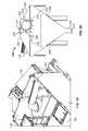
- FIGS. 1A-1Dare multiple views of an example of a filtration system carried by the particulate storage fracking trailer.
- FIG. 2Ais an example of a filtration system.
- FIG. 2Bis an example of an airlock valve connected to the filtration system.
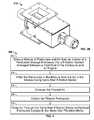
- FIG. 3is a flowchart of an example process of filtering particulate in a mixture of particulate and air.
- a particulate storage fracking trailerincludes a particulate storage enclosure which can be filled with particulate by mixing the particulate with air and flowing the mixture into the enclosure. As the enclosure fills with particulate, the air can exit the enclosure, carrying with it some of the particulate.
- the filtration systemwhich is connected to the particulate storage enclosure, can filter the particulate from a mixture of particulate and air exiting the enclosure.
- An exhaust fan included in the filtration systemcauses the mixture to be flowed through filtration media that captures the particulate in the mixture thereby separating the particulate from the air.
- the filtration systemincludes a vent through which the filtered air flows to the exterior of the particulate storage enclosure, and a collection system to collect the filtered particulate.
- the filtration systemcan be arranged at a front end of the fracking trailer between the particulate storage enclosure and an engine that provides power to the filtration system.
- the filtration system described herecan provide one or more of the following potential advantages. Relative to filtration systems that use many filters to filter the mixture of particulate and air, the filtration system described here can be simpler in construction, lighter in weight, smaller in size, and cheaper. Consequently, such a filtration system can be sufficiently compact to fit in a front end of the trailer, for example, between the engine and the particulate storage enclosure. Positioning the filtration system in the front end can decrease a load on a rear axle of the trailer and can decrease or prevent wear due to a cantilever effect caused if the filtration system were positioned at a rear end of the truck.
- a fracking trailer carrying the lighter weight filtration systemmay, in certain instances, be below the weight permitted load for road travel under regulations established by the governing bodies, such as The United States Department of Transportation. This can result in a decrease in costs associated with transporting the fracking trailer.
- the filtration systemcan use nano-filtration media that are more efficient relative to tubular filter cartridges.
- the nano-filtration mediacan provide more surface area to capture particulates relative to tubular filter cartridges, and additionally can contribute to a decrease in the size and the weight of the filtration system.
- the filtration systemcan protect not only the personnel working with or around the fracking trailer but also the environment by decreasing or removing potentially hazardous particulates from the air being exhausted from the particulate storage enclosure.
- the filtration systemcan also enable the fracking operations to be in compliance with government regulations issued, for example, by Occupational Safety and Health Administration (OSHA).
- OSHAOccupational Safety and Health Administration
- FIG. 1Ashows an example of a particulate storage fracking trailer system 100 that includes a trailer frame 104 with wheels 116 .
- the trailer frame 104carries a particulate storage enclosure 102 , which has a front end 110 and a rear end 114 .
- the trailer frame 104also carries an engine 106 , which is arranged at the front end 110 of the particulate storage enclosure 102 such that the front end 110 is proximal to the engine 106 while the rear end 114 is distal to the engine 106 .
- the engine 106is an engine of a hydraulic power system.
- the engine 106can drive a hydraulic pump that provides hydraulic pressure and flow to power various systems.
- the engine 106may also drive a generator to provide electrical power to various systems.
- the trailer frame 104carries a filtration system 108 , which is connected to the particulate storage enclosure 102 .
- the particulate storage enclosure 102 , the engine 106 , and the filtration system 108can be mounted to the trailer frame 104 to be carried and transported by a tractor that can be connected to a tongue end 118 of the trailer system 100 .
- the filtration system 108can be proximate to the tongue end 118 of the trailer system 100 , and be arranged between the particulate storage enclosure 102 and the engine 106 ( FIG. 1B ).
- the filtration system 108can be arranged such that a height of the filtration system 108 is greater than that of the engine 106 and is less than or equal to a trailer top height.
- the particulate storage enclosure 102can include a hatch 130 through which the air carrying the particulate can be flowed, for example, through a 4-inch blower (not shown) connected to the hatch 130 .
- the enclosure 102can be partitioned into multiple bins, each of which can have holes cut in the top middle portion of the bin wall.
- the mixture of particulate and aircan be blown into each partition through a respective hatch that can be sealed by a respective lid.
- a hatch lidcan include a rubber seal surrounding a flange and a plate (for example, a 45 lb plate) with a hole drilled in the middle that attaches to the lid.
- the filtration system 108can receive the mixture from an interior of the enclosure 102 , filter particulate from the air, and exhaust filtered air.
- the filtration system 108can receive power from the engine 106 to perform these operations.
- the filtration system 108can include an inlet pipe 120 positioned in the interior of the enclosure 102 ( FIG. 1D ). The filtration system 108 can draw the mixture of particulate and air from the interior of the enclosure 102 through the inlet 120 , and filter the particulate in the mixture from the air in the mixture, as described below with reference to FIG. 2A .
- FIG. 2Ais an example of a filtration system 108 to which the engine 106 provides power to filter the particulate from the air in the mixture.
- the filtration system 108can include an exhaust fan 214 (for example, a Cincinnati Fan PB-15A 14 ⁇ 31 ⁇ 4 radial wheel configured to deliver 2000 CFM at 4.0′′ of water column at 3000 RPM provided by Cincinnati Fan, Mason, Ohio) that can cause the mixture of the particulate and air to flow through the filtration system 108 , for example, by creating a suction.
- the inlet 120can be a pipe, for example, of 12′′ diameter, which has been sectioned out and welded to an expanded metal that covers a portion of a surface area of the pipe.
- the portion of the pipe that has the covered surface areacan face the blower that blows the mixture of particulate and sand into the particulate storage enclosure 102 .
- This arrangementcan prevent the mixture from flowing directly into the inlet 120 due to the suction created by the exhaust fan 214 .
- the filtration system 108can include a particulate filter to separate the particulates from the mixture and a collection system 206 to collect the separated particulates.
- the particulate filter(for example, Donaldson Torit® PowerCore® CPV model CPV2 provided by Donaldson Torit, Inc. of Minneapolis, Minn.) can be arranged outside the enclosure 102 and connected to the inlet to receive the mixture of particulate and air from the interior of the particulate storage enclosure.
- the filtration system 102can include more than one particulate filter, for example, a first particulate filter 202 and a second particulate filter 204 connected to each other by a connection pipe 240 .
- the mixture received by the inlet 120can be flowed through the particulate filter resulting in particulate being separated from the air.
- the exhaust fan 214can be connected to one of the two particulate filters to create suction in the filtration system 108 .
- the exhaust fan 214can be driven by a hydraulic motor, for example, a Parker M2B16912S20NB 5 HP hydraulic motor rated at 3450 RPM (provided by Parker Hannifin Corp., Cleveland, Ohio).
- the exhaust fan 214can include a vent 250 through which the air, from which the particulate has been filtered, can be exhausted.
- the particulate filtercan include nano-fiber filtration media (for example, Donaldson Torit® PowerCore® CP Filter Pack provided by Donaldson Torit, Inc. of Minneapolis, Minn.) to filter the particulate from the air.
- the nano-fiber filtration mediacan be configured as a flat filter cartridge housed in triangular housings.
- Each of the particulate filters 202 and 204can include more than one nano-fiber filtration media cartridge.
- each particulate filtercan include two such cartridges.
- the housingscan have lids with handles that can be opened to place and retrieve the nano-fiber filtration media.
- Each particulate filtercan have more than one nano-fiber filtration cartridge.
- the nano-fiber filtration mediacan include micro-webbings that collectively have larger surface area relative to tubular cartridge filters that are of the same size as the particulate filter but use paper or cloth filters to filter particulate. Consequently, the nano-fiber filtration media offers better filtration capacity and efficiency relative to the tubular filters with paper or cloth filters. Some of the particulates that the nano-fiber filtration media filters can be lodged in the micro-webbings of the nano-fiber filtration media. To dislodge such particles, the filtration system 108 can include air flow systems to pulse air through the nano-fiber filtration media.
- the air flow systemscan continuously provide pulsed air to the particulate filter to clean the nano-fiber filtration media.
- a compressed air manifold(not shown), for example, a 5′′ ⁇ 5′′ ⁇ 18′ air tank, can be connected to the air flow systems to supply the compressed air that can be pulsed as air jets.
- An air compressor(not shown) can be carried by the trailer frame 104 and be connected to the air tank to keep the air tank filled with compressed air, for example, at a pressure of 90-100 PSIG.
- the air compressorcan be mounted anywhere on the trailer frame 104 and need not be mounted next to the particulate filters.
- the air flow systemscan be connected to diaphragm valves (for example, using 1′′ air hoses with swivel male connectors) and solenoids to control the pulsing of the air jets into the nano-fiber filtration media through connectors (for example, connector 232 for particulate filter 202 and connector 234 for particulate filter 204 ).
- connectorsfor example, connector 232 for particulate filter 202 and connector 234 for particulate filter 204 .
- control signalscan be sent from a signal box (for example, including a pulse timer board) to the air flow systems to pulse air at a rate of 15 to 30 seconds.
- the signal box for each particulate filtercan be placed adjacent the particulate filter, for example, in slots 216 , 218 . Together, the first particulate filter 202 and the second particulate filter 204 can be rated for 2000 CFM.
- a pressure gaugecan be connected to the particulate filter.
- a decision to change the nano-fiber filtration media in the particulate filtercan be made based on the pressure reading. For example, if the pressure according to the pressure gauge does not decrease below six inches of water column after the nano-fiber filtration media have been pulsed with jets from the air flow systems, the filtration media may need to be changed.
- the collection system 206can receive and collect the particulate filtered from the mixture, for example, for disposal or for reuse.
- the collection system 206can be arranged below the first particulate filter 202 and the second particulate filter 204 , and can be connected to the filters by a plenum 220 such that particulate filtered by the nano-filtration media fall into the collection system 206 .
- the plenum 220can be connected between the particulate filters and the hopper 208 at an angle to accommodate the engine 106 arranged on the trailer frame 104 next to the filtration system 108 .
- the collection system 206can include a hopper 208 , for example, attached to the plenum 220 , to receive the particles that fall from the particulate filter during filtering as well as pulsed air cleaning
- the hopper 208can be a flanged, triangular hopper made of 12 gauge steel.
- the hopper 208can include a box extruding on the back that penetrates the front bin wall of the particulate storage enclosure 102 with bolt pattern for 12′′ manifolding.
- the hopper 208can be connected to a chute 210 to which an airlock valve 212 can be connected.
- the airlock valve 212which can be an airlock rotary valve (provided by Smoot Company, Kansas City, Kans.) as shown in FIG. 2B , can be configured to permit the particulate filtered from the mixture to flow out of the collection system 206 through an outlet of the chute 210 while limiting flow of air out of the collection system 206 .
- the airlock valve 212can be cylindrical and can include multiple vanes that can be continuously spun at low speed with a hydraulic motor. Particulates that fall into the hopper 208 fall into a space between two adjacent vanes.
- the hydraulic motor to which the airlock valve 212 is connectedcan be powered by the engine 106 . In general, all hydraulic operations and electronic operations implemented by the systems described above can be powered by the engine 106 .
- FIG. 3is a flowchart of an example process 300 of filtering particulate in a mixture of particulate and air.
- the process 300can be implemented by a filtration system that is carried a particulate fracking storage trailer, for example, the filtration system 108 .
- the filtration system 108can draw a mixture of particulate and air from an interior of the particulate storage enclosure 102 carried by a trailer frame 104 with wheels 116 .
- the filtration system 108can be carried by the trailer frame 104 and be connected to the front end 110 of the particulate storage enclosure 102 that is proximal to the engine 106 also carried by the trailer frame 104 .
- the filtration system 104can filter the particulate in the mixture from the air in the mixture.
- the filtration system 108can exhaust the filtered air.
- the collection system 206can collect the filtered particulate.
- the air flow systemscan pulse air through the nano-fiber filtration media to dislodge particulate lodged in the nano-fiber filtration media.
Landscapes
- Life Sciences & Earth Sciences (AREA)
- Engineering & Computer Science (AREA)
- Geology (AREA)
- Mining & Mineral Resources (AREA)
- Physics & Mathematics (AREA)
- Environmental & Geological Engineering (AREA)
- Fluid Mechanics (AREA)
- General Life Sciences & Earth Sciences (AREA)
- Geochemistry & Mineralogy (AREA)
- Filtering Of Dispersed Particles In Gases (AREA)
Abstract
Description
Claims (23)
Priority Applications (1)
| Application Number | Priority Date | Filing Date | Title |
|---|---|---|---|
| US13/651,742US8870990B2 (en) | 2012-10-15 | 2012-10-15 | Filtration system for a particulate storage fracking trailer |
Applications Claiming Priority (1)
| Application Number | Priority Date | Filing Date | Title |
|---|---|---|---|
| US13/651,742US8870990B2 (en) | 2012-10-15 | 2012-10-15 | Filtration system for a particulate storage fracking trailer |
Publications (2)
| Publication Number | Publication Date |
|---|---|
| US20140102301A1 US20140102301A1 (en) | 2014-04-17 |
| US8870990B2true US8870990B2 (en) | 2014-10-28 |
Family
ID=50474184
Family Applications (1)
| Application Number | Title | Priority Date | Filing Date |
|---|---|---|---|
| US13/651,742Expired - Fee RelatedUS8870990B2 (en) | 2012-10-15 | 2012-10-15 | Filtration system for a particulate storage fracking trailer |
Country Status (1)
| Country | Link |
|---|---|
| US (1) | US8870990B2 (en) |
Cited By (7)
| Publication number | Priority date | Publication date | Assignee | Title |
|---|---|---|---|---|
| US20140190356A1 (en)* | 2013-01-10 | 2014-07-10 | Brian Barrett | Silica Reduction Cover |
| US20170234608A1 (en)* | 2014-10-30 | 2017-08-17 | Mars Company | Refrigerated storage unit |
| US10023381B2 (en) | 2013-01-10 | 2018-07-17 | Black Bow Sdr, Llc | Textile silica reduction system |
| US11066259B2 (en) | 2016-08-24 | 2021-07-20 | Halliburton Energy Services, Inc. | Dust control systems for bulk material containers |
| US11186454B2 (en) | 2016-08-24 | 2021-11-30 | Halliburton Energy Services, Inc. | Dust control systems for discharge of bulk material |
| US20230109325A1 (en)* | 2012-11-16 | 2023-04-06 | U.S. Well Services, LLC | Wireline power supply during electric powered fracturing operations |
| US20240042368A1 (en)* | 2020-08-05 | 2024-02-08 | Agco International Gmbh | Self-Cleaning Air Filter System |
Families Citing this family (5)
| Publication number | Priority date | Publication date | Assignee | Title |
|---|---|---|---|---|
| US10464071B2 (en)* | 2013-09-18 | 2019-11-05 | Schlumberger Technology Corporation | System and method for preparing a treatment fluid |
| US11773315B2 (en) | 2016-03-01 | 2023-10-03 | Schlumberger Technology Corporation | Well treatment methods |
| BR202017027655Y1 (en)* | 2017-12-20 | 2020-04-07 | Teixeira Goethel Enilton | self-propelled equipment for street sweeping and / or weeding |
| US12338772B2 (en) | 2019-09-13 | 2025-06-24 | Bj Energy Solutions, Llc | Systems, assemblies, and methods to enhance intake air flow to a gas turbine engine of a hydraulic fracturing unit |
| US11002189B2 (en)* | 2019-09-13 | 2021-05-11 | Bj Energy Solutions, Llc | Mobile gas turbine inlet air conditioning system and associated methods |
Citations (13)
| Publication number | Priority date | Publication date | Assignee | Title |
|---|---|---|---|---|
| US4723969A (en)* | 1986-09-22 | 1988-02-09 | Demarco Thomas M | Vacuum loader and process for removing asbestos and other hazardous material |
| US4820315A (en)* | 1987-11-27 | 1989-04-11 | Demarco Thomas M | Vacuum loader and process for removing asbestos and other particulate material |
| US5053063A (en)* | 1988-08-18 | 1991-10-01 | Sisk David E | Dust filtering and collection system |
| US5199354A (en)* | 1988-11-18 | 1993-04-06 | Tps Technologies, Inc. | Mobile soil remediation system |
| US5762664A (en)* | 1996-12-18 | 1998-06-09 | National Tool And Equipment, Inc. | Mobile vessel for removal of noxious fumes |
| US5873919A (en)* | 1995-06-07 | 1999-02-23 | Simon Roofing & Sheet Metal Corp. | System for removal of noxious fumes |
| US6736885B2 (en)* | 2001-08-21 | 2004-05-18 | Dolores Kaiser | Refrigerator air filtration system |
| US20090255227A1 (en) | 2003-12-22 | 2009-10-15 | Donaldson Company, Inc. | Seal arrangement for filter element; filter element assembly; and, methods |
| US7694703B2 (en) | 2002-07-03 | 2010-04-13 | Gradmatic Equipment Inc. | Apparatus for dispensing particulate material and components therefor |
| US20100293906A1 (en) | 2007-09-07 | 2010-11-25 | Donaldson Company, Inc. | Air filter assembly; components thereof and methods |
| US20110083559A1 (en) | 2009-10-14 | 2011-04-14 | Thomas Donald Raether | Filter cartridge with seal member and methods |
| US8118900B2 (en) | 2009-09-30 | 2012-02-21 | Donaldson Company, Inc. | Dust collector and methods |
| US8226786B2 (en) | 2003-03-18 | 2012-07-24 | Donaldson Company, Inc. | Process and materials for coiling z-filter media, and/or closing flutes of filter media; and, products |
- 2012
- 2012-10-15USUS13/651,742patent/US8870990B2/ennot_activeExpired - Fee Related
Patent Citations (13)
| Publication number | Priority date | Publication date | Assignee | Title |
|---|---|---|---|---|
| US4723969A (en)* | 1986-09-22 | 1988-02-09 | Demarco Thomas M | Vacuum loader and process for removing asbestos and other hazardous material |
| US4820315A (en)* | 1987-11-27 | 1989-04-11 | Demarco Thomas M | Vacuum loader and process for removing asbestos and other particulate material |
| US5053063A (en)* | 1988-08-18 | 1991-10-01 | Sisk David E | Dust filtering and collection system |
| US5199354A (en)* | 1988-11-18 | 1993-04-06 | Tps Technologies, Inc. | Mobile soil remediation system |
| US5873919A (en)* | 1995-06-07 | 1999-02-23 | Simon Roofing & Sheet Metal Corp. | System for removal of noxious fumes |
| US5762664A (en)* | 1996-12-18 | 1998-06-09 | National Tool And Equipment, Inc. | Mobile vessel for removal of noxious fumes |
| US6736885B2 (en)* | 2001-08-21 | 2004-05-18 | Dolores Kaiser | Refrigerator air filtration system |
| US7694703B2 (en) | 2002-07-03 | 2010-04-13 | Gradmatic Equipment Inc. | Apparatus for dispensing particulate material and components therefor |
| US8226786B2 (en) | 2003-03-18 | 2012-07-24 | Donaldson Company, Inc. | Process and materials for coiling z-filter media, and/or closing flutes of filter media; and, products |
| US20090255227A1 (en) | 2003-12-22 | 2009-10-15 | Donaldson Company, Inc. | Seal arrangement for filter element; filter element assembly; and, methods |
| US20100293906A1 (en) | 2007-09-07 | 2010-11-25 | Donaldson Company, Inc. | Air filter assembly; components thereof and methods |
| US8118900B2 (en) | 2009-09-30 | 2012-02-21 | Donaldson Company, Inc. | Dust collector and methods |
| US20110083559A1 (en) | 2009-10-14 | 2011-04-14 | Thomas Donald Raether | Filter cartridge with seal member and methods |
Non-Patent Citations (6)
| Title |
|---|
| Aircleaning Technologies, "Halliburton CPV2 Twin" 2012 (1 page). |
| Halliburton, "Model FSR-2500 Mountain Mover Proppant Storage/Conveyor" 2012 (1 page). |
| National Oilwell Varco, "Sand Storage Tanks and Belt Conveyors" http://www.nov.com/Well-Service-and-Completion/Frac-Sand-Handling-Equipment/Sand-Storage-Tanks.aspx, Sep. 5, 2012 (1 page). |
| National Oilwell Varco, "Sand Storage Tanks and Belt Conveyors" http://www.nov.com/Well—Service—and—Completion/Frac—Sand—Handling—Equipment/Sand—Storage—Tanks.aspx, Sep. 5, 2012 (1 page). |
| Photo of an Appco model DCS 580 Quad dust collection system, photo taken Jun. 18, 2012. |
| Smoot, "6x6 Hydraulic Drive" Aug. 8, 2012 (1 page). |
Cited By (13)
| Publication number | Priority date | Publication date | Assignee | Title |
|---|---|---|---|---|
| US12009762B2 (en)* | 2012-11-16 | 2024-06-11 | U.S. Well Services, LLC | Wireline power supply during electric powered fracturing operations |
| US12438480B2 (en) | 2012-11-16 | 2025-10-07 | U.S. Well Services, LLC | Wireline power supply during electric powered fracturing operations |
| US20230109325A1 (en)* | 2012-11-16 | 2023-04-06 | U.S. Well Services, LLC | Wireline power supply during electric powered fracturing operations |
| US9440174B2 (en)* | 2013-01-10 | 2016-09-13 | Black Bow Sdr, Llc | Silica reduction cover |
| US10023381B2 (en) | 2013-01-10 | 2018-07-17 | Black Bow Sdr, Llc | Textile silica reduction system |
| US10526134B2 (en) | 2013-01-10 | 2020-01-07 | Black Bow Sdr, Llc | Textile silica reduction system |
| US20140190356A1 (en)* | 2013-01-10 | 2014-07-10 | Brian Barrett | Silica Reduction Cover |
| US20170234608A1 (en)* | 2014-10-30 | 2017-08-17 | Mars Company | Refrigerated storage unit |
| US10337790B2 (en)* | 2014-10-30 | 2019-07-02 | Mars Company | Refrigerated storage unit |
| US11066259B2 (en) | 2016-08-24 | 2021-07-20 | Halliburton Energy Services, Inc. | Dust control systems for bulk material containers |
| US11186454B2 (en) | 2016-08-24 | 2021-11-30 | Halliburton Energy Services, Inc. | Dust control systems for discharge of bulk material |
| US20240042368A1 (en)* | 2020-08-05 | 2024-02-08 | Agco International Gmbh | Self-Cleaning Air Filter System |
| US12090439B2 (en)* | 2020-08-05 | 2024-09-17 | Agco International Gmbh | Self-cleaning air filter system |
Also Published As
| Publication number | Publication date |
|---|---|
| US20140102301A1 (en) | 2014-04-17 |
Similar Documents
| Publication | Publication Date | Title |
|---|---|---|
| US8870990B2 (en) | Filtration system for a particulate storage fracking trailer | |
| AU2021202269B2 (en) | Conveyor with integrated dust collector system | |
| US8110115B2 (en) | Mobile water treatment | |
| US10457501B2 (en) | Systems and methods for converter bed unloading and loading | |
| US4774974A (en) | System for removing asbestos from structures | |
| US6936085B2 (en) | Vacuum loader | |
| EP1757350A2 (en) | Vacuum loader | |
| EP3437711B1 (en) | Mobile dust extraction device | |
| CN105555388B (en) | Modular cleaner for airborne dust with removable tank | |
| US20120012309A1 (en) | Flow Back Recovery System | |
| US20140010603A1 (en) | Portable Materials Storage Tank for Use With Vacuum Truck Pneumatic Transfer System | |
| US20140017018A1 (en) | Vacuum Truck With Pneumatic Transfer System | |
| CN113152554A (en) | Emergency rescue equipment for collapse of building | |
| US9434049B2 (en) | Apparatus and method for providing a modular abrasive blasting and recovery system | |
| US20240117765A1 (en) | Systems, assemblies, and methods for treatment/filtration of intake air flows to a gas turbine engine of a hydraulic fracturing unit | |
| CN208450101U (en) | Trailing vacuum suction cleaning device | |
| US9707594B2 (en) | Lead and rubber reclamation apparatus and process | |
| CN201098595Y (en) | Cement dust purification and recovery device for oil field cementing cement truck | |
| CN115506734B (en) | Sequential drilling charged synergistic multistage filtering dust removal device and method | |
| CN214779270U (en) | Emergency rescue equipment for collapse of building | |
| CN214764314U (en) | Gas-solid separation device of emergency rescue equipment and emergency rescue equipment thereof | |
| CN211358173U (en) | Special dust collector for railway track grinding wagon | |
| US20140053917A1 (en) | Dual stage flow back recovery system | |
| HK40004300B (en) | Mobile dust extraction device | |
| CA2817499C (en) | Portable materials storage tank for use with vacuum truck pneumatic transfer system |
Legal Events
| Date | Code | Title | Description |
|---|---|---|---|
| AS | Assignment | Owner name:HALLIBURTON ENERGY SERVICES, INC., MINNESOTA Free format text:ASSIGNMENT OF ASSIGNORS INTEREST;ASSIGNORS:MARKS, ALEXANDER LYNN;COVINGTON, KARY LAYNE;SANDERS, JOHNNY RAY, JR.;REEL/FRAME:030050/0964 Effective date:20121015 | |
| AS | Assignment | Owner name:HALLIBURTON ENERGY SERVICES, INC., TEXAS Free format text:CORRECTIVE ASSIGNMENT TO CORRECT ASSIGNEE ADDRESS PREVIOUSLY RECORDED ON REEL 030050 FRAME 0964. ASSIGNOR(S) HEREBY CONFIRMS THE ASSIGNMENT OF ASSIGNORS' INTEREST;ASSIGNORS:MARKS, ALEXANDER LYNN;COVINGTON, KARY LAYNE;SANDERS, JR., JOHNNY RAY;REEL/FRAME:030209/0671 Effective date:20121015 | |
| FEPP | Fee payment procedure | Free format text:PAYOR NUMBER ASSIGNED (ORIGINAL EVENT CODE: ASPN); ENTITY STATUS OF PATENT OWNER: LARGE ENTITY | |
| STCF | Information on status: patent grant | Free format text:PATENTED CASE | |
| MAFP | Maintenance fee payment | Free format text:PAYMENT OF MAINTENANCE FEE, 4TH YEAR, LARGE ENTITY (ORIGINAL EVENT CODE: M1551) Year of fee payment:4 | |
| CC | Certificate of correction | ||
| FEPP | Fee payment procedure | Free format text:MAINTENANCE FEE REMINDER MAILED (ORIGINAL EVENT CODE: REM.); ENTITY STATUS OF PATENT OWNER: LARGE ENTITY | |
| LAPS | Lapse for failure to pay maintenance fees | Free format text:PATENT EXPIRED FOR FAILURE TO PAY MAINTENANCE FEES (ORIGINAL EVENT CODE: EXP.); ENTITY STATUS OF PATENT OWNER: LARGE ENTITY | |
| STCH | Information on status: patent discontinuation | Free format text:PATENT EXPIRED DUE TO NONPAYMENT OF MAINTENANCE FEES UNDER 37 CFR 1.362 | |
| FP | Lapsed due to failure to pay maintenance fee | Effective date:20221028 |