US8870957B2 - Implant for mammalian bony segment stabilization - Google Patents
Implant for mammalian bony segment stabilizationDownload PDFInfo
- Publication number
- US8870957B2 US8870957B2US12/398,111US39811109AUS8870957B2US 8870957 B2US8870957 B2US 8870957B2US 39811109 AUS39811109 AUS 39811109AUS 8870957 B2US8870957 B2US 8870957B2
- Authority
- US
- United States
- Prior art keywords
- partial
- central opening
- openings
- width
- length
- Prior art date
- Legal status (The legal status is an assumption and is not a legal conclusion. Google has not performed a legal analysis and makes no representation as to the accuracy of the status listed.)
- Active, expires
Links
- 239000007943implantSubstances0.000titleabstractdescription68
- 230000006641stabilisationEffects0.000titleabstractdescription26
- 238000011105stabilizationMethods0.000titleabstractdescription26
- 238000000034methodMethods0.000claimsdescription10
- 230000000975bioactive effectEffects0.000claimsdescription5
- 239000012190activatorSubstances0.000claimsdescription3
- 230000008468bone growthEffects0.000claimsdescription3
- 230000000087stabilizing effectEffects0.000claimsdescription3
- 239000000463materialSubstances0.000abstractdescription4
- 229910052588hydroxylapatiteInorganic materials0.000description4
- XYJRXVWERLGGKC-UHFFFAOYSA-Dpentacalcium;hydroxide;triphosphateChemical compound[OH-].[Ca+2].[Ca+2].[Ca+2].[Ca+2].[Ca+2].[O-]P([O-])([O-])=O.[O-]P([O-])([O-])=O.[O-]P([O-])([O-])=OXYJRXVWERLGGKC-UHFFFAOYSA-D0.000description4
- 239000004696Poly ether ether ketoneSubstances0.000description2
- 230000008878couplingEffects0.000description2
- 238000010168coupling processMethods0.000description2
- 238000005859coupling reactionMethods0.000description2
- 238000010586diagramMethods0.000description2
- 229910003460diamondInorganic materials0.000description2
- 239000010432diamondSubstances0.000description2
- 229920002530polyetherether ketonePolymers0.000description2
- 229920000642polymerPolymers0.000description2
- OYPRJOBELJOOCE-UHFFFAOYSA-NCalciumChemical compound[Ca]OYPRJOBELJOOCE-UHFFFAOYSA-N0.000description1
- RTAQQCXQSZGOHL-UHFFFAOYSA-NTitaniumChemical compound[Ti]RTAQQCXQSZGOHL-UHFFFAOYSA-N0.000description1
- 230000001154acute effectEffects0.000description1
- 230000006978adaptationEffects0.000description1
- 210000003484anatomyAnatomy0.000description1
- 239000000560biocompatible materialSubstances0.000description1
- 210000000988bone and boneAnatomy0.000description1
- 229910052791calciumInorganic materials0.000description1
- 239000011575calciumSubstances0.000description1
- 238000000576coating methodMethods0.000description1
- 230000012010growthEffects0.000description1
- 238000002513implantationMethods0.000description1
- 238000003780insertionMethods0.000description1
- 230000037431insertionEffects0.000description1
- 239000003550markerSubstances0.000description1
- 229910052751metalInorganic materials0.000description1
- 239000002184metalSubstances0.000description1
- 229910001092metal group alloyInorganic materials0.000description1
- 150000002739metalsChemical class0.000description1
- 238000006467substitution reactionMethods0.000description1
- 229910052715tantalumInorganic materials0.000description1
- GUVRBAGPIYLISA-UHFFFAOYSA-Ntantalum atomChemical compound[Ta]GUVRBAGPIYLISA-UHFFFAOYSA-N0.000description1
- 229920001169thermoplasticPolymers0.000description1
- 239000004416thermosoftening plasticSubstances0.000description1
- 239000010936titaniumSubstances0.000description1
- 229910052719titaniumInorganic materials0.000description1
Images


Classifications
- A—HUMAN NECESSITIES
- A61—MEDICAL OR VETERINARY SCIENCE; HYGIENE
- A61F—FILTERS IMPLANTABLE INTO BLOOD VESSELS; PROSTHESES; DEVICES PROVIDING PATENCY TO, OR PREVENTING COLLAPSING OF, TUBULAR STRUCTURES OF THE BODY, e.g. STENTS; ORTHOPAEDIC, NURSING OR CONTRACEPTIVE DEVICES; FOMENTATION; TREATMENT OR PROTECTION OF EYES OR EARS; BANDAGES, DRESSINGS OR ABSORBENT PADS; FIRST-AID KITS
- A61F2/00—Filters implantable into blood vessels; Prostheses, i.e. artificial substitutes or replacements for parts of the body; Appliances for connecting them with the body; Devices providing patency to, or preventing collapsing of, tubular structures of the body, e.g. stents
- A61F2/02—Prostheses implantable into the body
- A61F2/30—Joints
- A61F2/44—Joints for the spine, e.g. vertebrae, spinal discs
- A61F2/4455—Joints for the spine, e.g. vertebrae, spinal discs for the fusion of spinal bodies, e.g. intervertebral fusion of adjacent spinal bodies, e.g. fusion cages
- A61F2/447—Joints for the spine, e.g. vertebrae, spinal discs for the fusion of spinal bodies, e.g. intervertebral fusion of adjacent spinal bodies, e.g. fusion cages substantially parallelepipedal, e.g. having a rectangular or trapezoidal cross-section
- A—HUMAN NECESSITIES
- A61—MEDICAL OR VETERINARY SCIENCE; HYGIENE
- A61F—FILTERS IMPLANTABLE INTO BLOOD VESSELS; PROSTHESES; DEVICES PROVIDING PATENCY TO, OR PREVENTING COLLAPSING OF, TUBULAR STRUCTURES OF THE BODY, e.g. STENTS; ORTHOPAEDIC, NURSING OR CONTRACEPTIVE DEVICES; FOMENTATION; TREATMENT OR PROTECTION OF EYES OR EARS; BANDAGES, DRESSINGS OR ABSORBENT PADS; FIRST-AID KITS
- A61F2/00—Filters implantable into blood vessels; Prostheses, i.e. artificial substitutes or replacements for parts of the body; Appliances for connecting them with the body; Devices providing patency to, or preventing collapsing of, tubular structures of the body, e.g. stents
- A61F2/02—Prostheses implantable into the body
- A61F2/28—Bones
- A61F2002/2817—Bone stimulation by chemical reactions or by osteogenic or biological products for enhancing ossification, e.g. by bone morphogenetic or morphogenic proteins [BMP] or by transforming growth factors [TGF]
- A—HUMAN NECESSITIES
- A61—MEDICAL OR VETERINARY SCIENCE; HYGIENE
- A61F—FILTERS IMPLANTABLE INTO BLOOD VESSELS; PROSTHESES; DEVICES PROVIDING PATENCY TO, OR PREVENTING COLLAPSING OF, TUBULAR STRUCTURES OF THE BODY, e.g. STENTS; ORTHOPAEDIC, NURSING OR CONTRACEPTIVE DEVICES; FOMENTATION; TREATMENT OR PROTECTION OF EYES OR EARS; BANDAGES, DRESSINGS OR ABSORBENT PADS; FIRST-AID KITS
- A61F2/00—Filters implantable into blood vessels; Prostheses, i.e. artificial substitutes or replacements for parts of the body; Appliances for connecting them with the body; Devices providing patency to, or preventing collapsing of, tubular structures of the body, e.g. stents
- A61F2/02—Prostheses implantable into the body
- A61F2/30—Joints
- A61F2002/30001—Additional features of subject-matter classified in A61F2/28, A61F2/30 and subgroups thereof
- A61F2002/30003—Material related properties of the prosthesis or of a coating on the prosthesis
- A61F2002/3006—Properties of materials and coating materials
- A61F2002/3008—Properties of materials and coating materials radio-opaque, e.g. radio-opaque markers
- A—HUMAN NECESSITIES
- A61—MEDICAL OR VETERINARY SCIENCE; HYGIENE
- A61F—FILTERS IMPLANTABLE INTO BLOOD VESSELS; PROSTHESES; DEVICES PROVIDING PATENCY TO, OR PREVENTING COLLAPSING OF, TUBULAR STRUCTURES OF THE BODY, e.g. STENTS; ORTHOPAEDIC, NURSING OR CONTRACEPTIVE DEVICES; FOMENTATION; TREATMENT OR PROTECTION OF EYES OR EARS; BANDAGES, DRESSINGS OR ABSORBENT PADS; FIRST-AID KITS
- A61F2/00—Filters implantable into blood vessels; Prostheses, i.e. artificial substitutes or replacements for parts of the body; Appliances for connecting them with the body; Devices providing patency to, or preventing collapsing of, tubular structures of the body, e.g. stents
- A61F2/02—Prostheses implantable into the body
- A61F2/30—Joints
- A61F2002/30001—Additional features of subject-matter classified in A61F2/28, A61F2/30 and subgroups thereof
- A61F2002/30108—Shapes
- A61F2002/3011—Cross-sections or two-dimensional shapes
- A61F2002/30159—Concave polygonal shapes
- A61F2002/30176—V-shaped
- A—HUMAN NECESSITIES
- A61—MEDICAL OR VETERINARY SCIENCE; HYGIENE
- A61F—FILTERS IMPLANTABLE INTO BLOOD VESSELS; PROSTHESES; DEVICES PROVIDING PATENCY TO, OR PREVENTING COLLAPSING OF, TUBULAR STRUCTURES OF THE BODY, e.g. STENTS; ORTHOPAEDIC, NURSING OR CONTRACEPTIVE DEVICES; FOMENTATION; TREATMENT OR PROTECTION OF EYES OR EARS; BANDAGES, DRESSINGS OR ABSORBENT PADS; FIRST-AID KITS
- A61F2/00—Filters implantable into blood vessels; Prostheses, i.e. artificial substitutes or replacements for parts of the body; Appliances for connecting them with the body; Devices providing patency to, or preventing collapsing of, tubular structures of the body, e.g. stents
- A61F2/02—Prostheses implantable into the body
- A61F2/30—Joints
- A61F2002/30001—Additional features of subject-matter classified in A61F2/28, A61F2/30 and subgroups thereof
- A61F2002/30316—The prosthesis having different structural features at different locations within the same prosthesis; Connections between prosthetic parts; Special structural features of bone or joint prostheses not otherwise provided for
- A61F2002/30535—Special structural features of bone or joint prostheses not otherwise provided for
- A61F2002/30593—Special structural features of bone or joint prostheses not otherwise provided for hollow
- A—HUMAN NECESSITIES
- A61—MEDICAL OR VETERINARY SCIENCE; HYGIENE
- A61F—FILTERS IMPLANTABLE INTO BLOOD VESSELS; PROSTHESES; DEVICES PROVIDING PATENCY TO, OR PREVENTING COLLAPSING OF, TUBULAR STRUCTURES OF THE BODY, e.g. STENTS; ORTHOPAEDIC, NURSING OR CONTRACEPTIVE DEVICES; FOMENTATION; TREATMENT OR PROTECTION OF EYES OR EARS; BANDAGES, DRESSINGS OR ABSORBENT PADS; FIRST-AID KITS
- A61F2/00—Filters implantable into blood vessels; Prostheses, i.e. artificial substitutes or replacements for parts of the body; Appliances for connecting them with the body; Devices providing patency to, or preventing collapsing of, tubular structures of the body, e.g. stents
- A61F2/02—Prostheses implantable into the body
- A61F2/30—Joints
- A61F2/30767—Special external or bone-contacting surface, e.g. coating for improving bone ingrowth
- A61F2/30771—Special external or bone-contacting surface, e.g. coating for improving bone ingrowth applied in original prostheses, e.g. holes or grooves
- A61F2002/30772—Apertures or holes, e.g. of circular cross section
- A61F2002/30784—Plurality of holes
- A61F2002/30785—Plurality of holes parallel
- A—HUMAN NECESSITIES
- A61—MEDICAL OR VETERINARY SCIENCE; HYGIENE
- A61F—FILTERS IMPLANTABLE INTO BLOOD VESSELS; PROSTHESES; DEVICES PROVIDING PATENCY TO, OR PREVENTING COLLAPSING OF, TUBULAR STRUCTURES OF THE BODY, e.g. STENTS; ORTHOPAEDIC, NURSING OR CONTRACEPTIVE DEVICES; FOMENTATION; TREATMENT OR PROTECTION OF EYES OR EARS; BANDAGES, DRESSINGS OR ABSORBENT PADS; FIRST-AID KITS
- A61F2/00—Filters implantable into blood vessels; Prostheses, i.e. artificial substitutes or replacements for parts of the body; Appliances for connecting them with the body; Devices providing patency to, or preventing collapsing of, tubular structures of the body, e.g. stents
- A61F2/02—Prostheses implantable into the body
- A61F2/30—Joints
- A61F2/30767—Special external or bone-contacting surface, e.g. coating for improving bone ingrowth
- A61F2/30771—Special external or bone-contacting surface, e.g. coating for improving bone ingrowth applied in original prostheses, e.g. holes or grooves
- A61F2002/30904—Special external or bone-contacting surface, e.g. coating for improving bone ingrowth applied in original prostheses, e.g. holes or grooves serrated profile, i.e. saw-toothed
- A61F2002/4475—
- A—HUMAN NECESSITIES
- A61—MEDICAL OR VETERINARY SCIENCE; HYGIENE
- A61F—FILTERS IMPLANTABLE INTO BLOOD VESSELS; PROSTHESES; DEVICES PROVIDING PATENCY TO, OR PREVENTING COLLAPSING OF, TUBULAR STRUCTURES OF THE BODY, e.g. STENTS; ORTHOPAEDIC, NURSING OR CONTRACEPTIVE DEVICES; FOMENTATION; TREATMENT OR PROTECTION OF EYES OR EARS; BANDAGES, DRESSINGS OR ABSORBENT PADS; FIRST-AID KITS
- A61F2/00—Filters implantable into blood vessels; Prostheses, i.e. artificial substitutes or replacements for parts of the body; Appliances for connecting them with the body; Devices providing patency to, or preventing collapsing of, tubular structures of the body, e.g. stents
- A61F2/02—Prostheses implantable into the body
- A61F2/30—Joints
- A61F2/44—Joints for the spine, e.g. vertebrae, spinal discs
- A61F2002/448—Joints for the spine, e.g. vertebrae, spinal discs comprising multiple adjacent spinal implants within the same intervertebral space or within the same vertebra, e.g. comprising two adjacent spinal implants
- A—HUMAN NECESSITIES
- A61—MEDICAL OR VETERINARY SCIENCE; HYGIENE
- A61F—FILTERS IMPLANTABLE INTO BLOOD VESSELS; PROSTHESES; DEVICES PROVIDING PATENCY TO, OR PREVENTING COLLAPSING OF, TUBULAR STRUCTURES OF THE BODY, e.g. STENTS; ORTHOPAEDIC, NURSING OR CONTRACEPTIVE DEVICES; FOMENTATION; TREATMENT OR PROTECTION OF EYES OR EARS; BANDAGES, DRESSINGS OR ABSORBENT PADS; FIRST-AID KITS
- A61F2/00—Filters implantable into blood vessels; Prostheses, i.e. artificial substitutes or replacements for parts of the body; Appliances for connecting them with the body; Devices providing patency to, or preventing collapsing of, tubular structures of the body, e.g. stents
- A61F2/02—Prostheses implantable into the body
- A61F2/30—Joints
- A61F2/46—Special tools for implanting artificial joints
- A61F2/4603—Special tools for implanting artificial joints for insertion or extraction of endoprosthetic joints or of accessories thereof
- A61F2002/4629—Special tools for implanting artificial joints for insertion or extraction of endoprosthetic joints or of accessories thereof connected to the endoprosthesis or implant via a threaded connection
- A—HUMAN NECESSITIES
- A61—MEDICAL OR VETERINARY SCIENCE; HYGIENE
- A61F—FILTERS IMPLANTABLE INTO BLOOD VESSELS; PROSTHESES; DEVICES PROVIDING PATENCY TO, OR PREVENTING COLLAPSING OF, TUBULAR STRUCTURES OF THE BODY, e.g. STENTS; ORTHOPAEDIC, NURSING OR CONTRACEPTIVE DEVICES; FOMENTATION; TREATMENT OR PROTECTION OF EYES OR EARS; BANDAGES, DRESSINGS OR ABSORBENT PADS; FIRST-AID KITS
- A61F2230/00—Geometry of prostheses classified in groups A61F2/00 - A61F2/26 or A61F2/82 or A61F9/00 or A61F11/00 or subgroups thereof
- A61F2230/0002—Two-dimensional shapes, e.g. cross-sections
- A61F2230/0028—Shapes in the form of latin or greek characters
- A61F2230/0054—V-shaped
- A—HUMAN NECESSITIES
- A61—MEDICAL OR VETERINARY SCIENCE; HYGIENE
- A61F—FILTERS IMPLANTABLE INTO BLOOD VESSELS; PROSTHESES; DEVICES PROVIDING PATENCY TO, OR PREVENTING COLLAPSING OF, TUBULAR STRUCTURES OF THE BODY, e.g. STENTS; ORTHOPAEDIC, NURSING OR CONTRACEPTIVE DEVICES; FOMENTATION; TREATMENT OR PROTECTION OF EYES OR EARS; BANDAGES, DRESSINGS OR ABSORBENT PADS; FIRST-AID KITS
- A61F2250/00—Special features of prostheses classified in groups A61F2/00 - A61F2/26 or A61F2/82 or A61F9/00 or A61F11/00 or subgroups thereof
- A61F2250/0058—Additional features; Implant or prostheses properties not otherwise provided for
- A61F2250/0096—Markers and sensors for detecting a position or changes of a position of an implant, e.g. RF sensors, ultrasound markers
- A61F2250/0098—Markers and sensors for detecting a position or changes of a position of an implant, e.g. RF sensors, ultrasound markers radio-opaque, e.g. radio-opaque markers
- A—HUMAN NECESSITIES
- A61—MEDICAL OR VETERINARY SCIENCE; HYGIENE
- A61F—FILTERS IMPLANTABLE INTO BLOOD VESSELS; PROSTHESES; DEVICES PROVIDING PATENCY TO, OR PREVENTING COLLAPSING OF, TUBULAR STRUCTURES OF THE BODY, e.g. STENTS; ORTHOPAEDIC, NURSING OR CONTRACEPTIVE DEVICES; FOMENTATION; TREATMENT OR PROTECTION OF EYES OR EARS; BANDAGES, DRESSINGS OR ABSORBENT PADS; FIRST-AID KITS
- A61F2310/00—Prostheses classified in A61F2/28 or A61F2/30 - A61F2/44 being constructed from or coated with a particular material
- A61F2310/00005—The prosthesis being constructed from a particular material
- A61F2310/00179—Ceramics or ceramic-like structures
- A61F2310/00293—Ceramics or ceramic-like structures containing a phosphorus-containing compound, e.g. apatite
- A—HUMAN NECESSITIES
- A61—MEDICAL OR VETERINARY SCIENCE; HYGIENE
- A61F—FILTERS IMPLANTABLE INTO BLOOD VESSELS; PROSTHESES; DEVICES PROVIDING PATENCY TO, OR PREVENTING COLLAPSING OF, TUBULAR STRUCTURES OF THE BODY, e.g. STENTS; ORTHOPAEDIC, NURSING OR CONTRACEPTIVE DEVICES; FOMENTATION; TREATMENT OR PROTECTION OF EYES OR EARS; BANDAGES, DRESSINGS OR ABSORBENT PADS; FIRST-AID KITS
- A61F2310/00—Prostheses classified in A61F2/28 or A61F2/30 - A61F2/44 being constructed from or coated with a particular material
- A61F2310/00005—The prosthesis being constructed from a particular material
- A61F2310/00359—Bone or bony tissue
Definitions
- Various implant embodiments described hereinrelate generally to stabilizing mammalian bony segments, including fenestrated implants to stabilize one or more mammalian bony segments.
- FIG. 1is a simplified diagram of mammalian bony segment stabilization architecture according to various embodiments.
- FIG. 2Ais a simplified, isometric front view of a mammalian bony segment stabilization implant according to various embodiments.
- FIG. 2Bis a simplified, isometric X-Y sectional front view of a mammalian bony segment stabilization implant according to various embodiments.
- FIG. 2Cis a simplified, isometric Y-Z sectional front view of a mammalian bony segment stabilization implant according to various embodiments.
- FIG. 2Dis a simplified, isometric X-Z sectional front view of a mammalian bony segment stabilization implant according to various embodiments.
- FIG. 2Eis a simplified, side view of a mammalian bony segment stabilization implant according to various embodiments.
- FIG. 2Fis a simplified, partial view of a mammalian bony segment stabilization implant top and bottom teeth according to various embodiments.
- FIG. 2Gis a simplified, top view of a mammalian bony segment stabilization implant according to various embodiments.
- FIG. 2His a simplified, front view of a mammalian bony segment stabilization implant according to various embodiments.
- FIG. 2Iis a simplified, rear view of a mammalian bony segment stabilization implant according to various embodiments.
- FIG. 2Jis a simplified, partial view of a mammalian bony segment stabilization implant side protrusions according to various embodiments.
- FIG. 2Kis a simplified, isometric front view of a mammalian bony segment stabilization implant including radio opaque elements according to various embodiments.
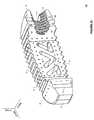
- FIG. 1is a simplified diagram of a mammalian bony segment stabilization architecture 220 according to various embodiments.
- the architecture 220includes one or more implants 10 inserted between bony regions 222 at multiple levels.
- one or more implants 10may be inserted laterally as shown between the top, two bony regions 222 .
- one or more implants 10may be inserted posteriorally as shown between the bottom, two bony regions 222 .
- one or more implants 10may be inserted laterally and one or more implants 10 may be inserted posteriorally between two bony regions 222 .
- the implants 10may inserted at any angle between two bony regions 222 as a function of anatomy adjacent to the two bony regions 222 .
- FIG. 2Ais a simplified, isometric front view of a mammalian bony segment stabilization implant 10 according to various embodiments.
- the implanthas an elongated shape including a front 16 , first side 24 , second side 22 , rear 18 , top 12 , and bottom 14 .
- the implant 10may include a large central fenestration extending from the top surface 12 to the bottom surface 14 .
- the implant 10may include partial fenestrations or porous openings 36 spaced periodically along the top and bottom surfaces 12 , 14 .
- the implant 10may further include fenestrations or porous openings 32 , 34 A, 34 B along one or more axis where one or more radio opaque markers 84 , 82 A, 82 B ( FIG. 2K ).
- the implant 10may further include partial or full lateral (along X-Axis) fenestrations or porous openings 38 in the side walls 12 , 14 extending to the central fenestration or opening 37 .
- the implant 10may further include several larger fenestrations or openings 42 , 44 , 46 extending through each side wall 12 , 14 to the central fenestration 37 .
- the fenestration or opening 42may be V-shaped and the fenestrations or openings 44 , 46 may be arrow shaped in an embodiment.
- the implant 10 top 12 and bottom surfaces 14may include a plurality of racked teeth 52 .
- the implant 10 side surfaces 22 , 24may include a plurality of protrusions 62 .
- the implant front surface 16may have sloped surfaces 15 coupling the front surface 16 to the top and bottom 12 , 14 surfaces (FIG. 2 E).
- the implant rear surface 18may also have sloped surfaces 17 coupling the rear surface 18 to the top and bottom 12 , 14 surfaces.
- the implant 10may be sized to be inserted between two lumbar vertebra.
- the implant's maximum height between the top surface 12 and bottom surface 14may be about 8 mm.
- the implant's maximum length between the front surface 16 and rear surface 18may be about 26 mm.
- the fenestrations or porous openings 32 , 34 A, and 34 Bmay have a diameter of about 1 mm
- the fenestrations or porous openings 36 , 38may have a diameter of about 0.25 mm.
- the central fenestration 37may have a maximum length of about 16 mm and a maximum width of about 5 mm.
- the fenestration 37 endsmay a radius of about 2.5 mm.
- the front surfaces 15may have a slope of about 25 degrees. Further the top and bottom surfaces 12 , 14 may have an effective radius of about 46 mm.
- the implant 10 rear surface 18may have a tool interface 74 including a threaded section 72 ( FIG. 2I ). In an embodiment the depth and height of the tool opening may be 2 mm and the threaded section 72 may have a diameter about 4 mm with a total depth of about 4 mm.
- the fenestrations or porous openings 36 on the top 12 and bottom 14 surfaces and fenestrations 38 or openings on the sides 22 , 24may have a spacing about 1.25 mm vertically and horizontally from each adjacent fenestration.
- the implant 10 top 12 and bottom 14 surfacesmay have teeth ( FIG. 2F ).
- the teeth 52may be spaced about 1.4 mm apart and have a height of about 0.6 mm.
- the teeth 52 surface 53may have reverse rack (relative to the implant 10 front 16 ) of about 52 degrees (obtuse) and the surface 54 having an acute angle relative to normal.
- the implant 10may be include a radio lucent material including polymers/thermoplastics such as PEEK (Polyetheretherketone).
- the radio markersmay include radio opaque materials including metal alloys such as titanium and tantalum.
- the implant 10includes a large central fenestration 37 , side fenestrations 38 , and top and bottom surface fenestrations 36 .
- the fenestrations or porous openings 36 , 37 , 38may enable bony in-growth in the implant 10 .
- the implant 10 materialmay include a bone growth activator or bio-active elements including a calcium based hydroxylapatite or hydroxyapatite.
- the implant 10 surfaces 12 , 14 , 16 , 18 , 22 , 24 and fenestration or porous opening 36 , 37 , 38 surfacesmay be coated with a bio-active element or coatings including a hydroxyapatite to encourage bony growth between a bony surface 222 and an implant 10 .
- the entire implant 10may be coated with one or more bio-active elements including a hydroxyapatite.
- FIG. 2Bis a simplified, isometric X-Y sectional front view of the mammalian bony segment stabilization implant 10 according to various embodiments.
- the side fenestrations 38may extend from a side surface 22 , 24 to the central fenestration 37 .
- FIG. 2Cis a simplified, isometric Y-Z sectional front view of the mammalian bony segment stabilization implant 10 according to various embodiments.
- the fenestration 32may extend through the implant 10 and the fenestrations 34 A, 34 B may extend from the top 12 and bottom 14 surfaces respectively to the tool engagement 74 thread 72 .
- FIG. 2Dis a simplified, isometric X-Z sectional front view of the mammalian bony segment stabilization implant 10 according to various embodiments.
- the side fenestrations 38 , 42 , 44 , 46may extend from a side surface 22 , 24 to the central fenestration 37 .
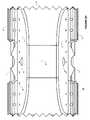
- FIG. 2Eis a simplified, left side view 24 of the mammalian bony segment stabilization implant 10 according to various embodiments.
- the side surfaces 22 , 24include a diamond knurl pattern 62 on a substantial section and racked teeth 52 along the top 12 and bottom 14 surfaces.
- FIG. 2Fis a simplified, partial view of the mammalian bony segment stabilization implant 10 top 12 and bottom 14 teeth 52 according to various embodiments.
- the teeth 52has a forward surface 53 and back surface 54 where the surfaces form a reverse rack relative the implant 10 front 16 to limit or prevent implant movement toward the rear surface 18 after implantation between bony segments 222 to be stabilized.
- FIG. 2Gis a simplified, top 12 view of the mammalian bony segment stabilization implant 10 according to various embodiments.
- the implant 10includes a large central fenestration 37 , radio opaque marker fenestrations 32 , 34 A, and plurality of partial, surface fenestrations or openings 36 .
- FIG. 2His a simplified, front view 16 of the mammalian bony segment stabilization implant 10 according to various embodiments.
- the implant 10 front 16includes sloped ends or surfaces 15 that may a user to distract a bony segment pair 222 when the implant 10 is inserted between the pair.
- FIG. 2Iis a simplified, rear 18 view of the mammalian bony segment stabilization implant 10 according to various embodiments.
- the implant 10 rear section 18may include a tool recess 74 including a threaded section 72 to enable a user to releasably engage the implant 10 for insertion or removal between a bony segment 222 pair.
- FIG. 2Jis a simplified, partial view of the mammalian bony segment stabilization implant 10 side 22 , 24 protrusions 62 according to various embodiments.
- the side protrusions 62may form a diamond knurl pattern where each protrusion 62 has a four-sided 63 , 64 , 65 , 66 pyramid shape.
- side fenestrations 38may be formed in some protrusions 62 where the fenestrations 38 may enable bony in-growth.
- FIG. 2Kis a simplified, isometric front view of the mammalian bony segment stabilization implant 10 including radio opaque elements or markers 82 A, 82 B, 84 according to various embodiments.
- the radio opaque elements or markers 82 A, 82 B, 84may be inserted into implant 10 fenestrations 34 A, 34 B, and 32 , respectively to enable a user to determine implant 10 placement between bony segments 222 via a radio wave generation device. It is noted that the implant 10 may be comprised of any biocompatible material including bone, polymers, and metals.
- inventive subject mattermay be referred to herein individually or collectively by the term “invention” merely for convenience and without intending to voluntarily limit the scope of this application to any single invention or inventive concept, if more than one is in fact disclosed.
- inventive conceptany arrangement calculated to achieve the same purpose may be substituted for the specific embodiments shown.
- This disclosureis intended to cover any and all adaptations or variations of various embodiments. Combinations of the above embodiments, and other embodiments not specifically described herein, will be apparent to those of skill in the art upon reviewing the above description.
Landscapes
- Health & Medical Sciences (AREA)
- Engineering & Computer Science (AREA)
- Biomedical Technology (AREA)
- Neurology (AREA)
- Orthopedic Medicine & Surgery (AREA)
- Cardiology (AREA)
- Oral & Maxillofacial Surgery (AREA)
- Transplantation (AREA)
- Heart & Thoracic Surgery (AREA)
- Vascular Medicine (AREA)
- Life Sciences & Earth Sciences (AREA)
- Animal Behavior & Ethology (AREA)
- General Health & Medical Sciences (AREA)
- Public Health (AREA)
- Veterinary Medicine (AREA)
- Prostheses (AREA)
Abstract
Description
Claims (16)
Priority Applications (1)
| Application Number | Priority Date | Filing Date | Title |
|---|---|---|---|
| US12/398,111US8870957B2 (en) | 2009-03-04 | 2009-03-04 | Implant for mammalian bony segment stabilization |
Applications Claiming Priority (1)
| Application Number | Priority Date | Filing Date | Title |
|---|---|---|---|
| US12/398,111US8870957B2 (en) | 2009-03-04 | 2009-03-04 | Implant for mammalian bony segment stabilization |
Publications (2)
| Publication Number | Publication Date |
|---|---|
| US20100228296A1 US20100228296A1 (en) | 2010-09-09 |
| US8870957B2true US8870957B2 (en) | 2014-10-28 |
Family
ID=42678903
Family Applications (1)
| Application Number | Title | Priority Date | Filing Date |
|---|---|---|---|
| US12/398,111Active2029-10-20US8870957B2 (en) | 2009-03-04 | 2009-03-04 | Implant for mammalian bony segment stabilization |
Country Status (1)
| Country | Link |
|---|---|
| US (1) | US8870957B2 (en) |
Cited By (18)
| Publication number | Priority date | Publication date | Assignee | Title |
|---|---|---|---|---|
| US9277928B2 (en) | 2013-03-11 | 2016-03-08 | Interventional Spine, Inc. | Method and apparatus for minimally invasive insertion of intervertebral implants |
| US9486149B2 (en) | 2011-03-10 | 2016-11-08 | Interventional Spine, Inc. | Method and apparatus for minimally invasive insertion of intervertebral implants |
| US9492194B2 (en) | 2011-03-10 | 2016-11-15 | Interventional Spine, Inc. | Method and apparatus for minimally invasive insertion of intervertebral implants |
| US9987051B2 (en) | 2015-01-27 | 2018-06-05 | K2M, Inc. | Interbody spacer |
| US9993353B2 (en) | 2013-03-14 | 2018-06-12 | DePuy Synthes Products, Inc. | Method and apparatus for minimally invasive insertion of intervertebral implants |
| US10028841B2 (en) | 2015-01-27 | 2018-07-24 | K2M, Inc. | Interbody spacer |
| USD847339S1 (en) | 2017-06-26 | 2019-04-30 | Advanced Research System, LLC | Spinal fusion cage |
| USD879295S1 (en) | 2017-02-13 | 2020-03-24 | Advance Research System, Llc | Spinal fusion cage |
| US10603182B2 (en)* | 2015-01-14 | 2020-03-31 | Stryker European Holdings I, Llc | Spinal implant with fluid delivery capabilities |
| US10835388B2 (en) | 2017-09-20 | 2020-11-17 | Stryker European Operations Holdings Llc | Spinal implants |
| USD907771S1 (en) | 2017-10-09 | 2021-01-12 | Pioneer Surgical Technology, Inc. | Intervertebral implant |
| US10959855B2 (en) | 2017-05-25 | 2021-03-30 | Stryker European Holdings I, Llc | Fusion cage with integrated fixation and insertion features |
| US11006981B2 (en) | 2017-07-07 | 2021-05-18 | K2M, Inc. | Surgical implant and methods of additive manufacturing |
| US11058551B2 (en) | 2016-12-16 | 2021-07-13 | Advance Research System, Llc | Interbody implant with concave profiled nose |
| US11147682B2 (en) | 2017-09-08 | 2021-10-19 | Pioneer Surgical Technology, Inc. | Intervertebral implants, instruments, and methods |
| US11737888B1 (en) | 2019-09-19 | 2023-08-29 | Advance Research System, Llc | Spinal fusion implant system and method |
| US12268613B2 (en) | 2015-01-14 | 2025-04-08 | Stryker European Operations Holdings Llc | Spinal implant with porous and solid surfaces |
| US12409045B2 (en) | 2019-09-16 | 2025-09-09 | Vb Spine Us Opco Llc | 3D printed cervical standalone implant |
Families Citing this family (17)
| Publication number | Priority date | Publication date | Assignee | Title |
|---|---|---|---|---|
| US8147554B2 (en)* | 2008-10-13 | 2012-04-03 | Globus Medical, Inc. | Intervertebral spacer |
| US8287597B1 (en) | 2009-04-16 | 2012-10-16 | Nuvasive, Inc. | Method and apparatus for performing spine surgery |
| AU2011281934B2 (en)* | 2010-07-23 | 2016-06-02 | Privelop-Spine Ag | Surgical implant |
| US8900309B2 (en) | 2010-08-31 | 2014-12-02 | Meditech Spine, Llc | Spinal implants |
| US9132021B2 (en) | 2011-10-07 | 2015-09-15 | Pioneer Surgical Technology, Inc. | Intervertebral implant |
| US9655746B2 (en) | 2011-11-09 | 2017-05-23 | Globus Medical, Inc. | Intervertebral spinal implant |
| GB2507965B (en)* | 2012-11-14 | 2018-12-19 | Steris Instrument Man Services Inc | Cage assembly for tibial tuberosity advancement procedure |
| US10478313B1 (en)* | 2014-01-10 | 2019-11-19 | Nuvasive, Inc. | Spinal fusion implant and related methods |
| CA2930123A1 (en) | 2015-05-18 | 2016-11-18 | Stryker European Holdings I, Llc | Partially resorbable implants and methods |
| US10292825B2 (en)* | 2016-06-27 | 2019-05-21 | Globus Medical, Inc. | Intervertebral spacer with chamfered edges |
| US10292834B2 (en)* | 2016-06-27 | 2019-05-21 | Globus Medical, Inc. | Intervertebral spacer with chamfered edges |
| CN107693171A (en)* | 2017-10-20 | 2018-02-16 | 常州华森医疗器械有限公司 | Thoracolumbar disk Invasive lumbar fusion device |
| US10682238B2 (en)* | 2018-05-08 | 2020-06-16 | Globus Medical, Inc. | Intervertebral spinal implant |
| US11051953B2 (en)* | 2019-07-31 | 2021-07-06 | Zavation Medical Products, Llc | Porous spinal implant |
| CN115038411A (en)* | 2020-01-31 | 2022-09-09 | 京瓷株式会社 | Vertebral implant and method for manufacturing vertebral implant |
| KR102370651B1 (en)* | 2020-02-06 | 2022-03-04 | 주식회사 지비에스커먼웰스 | Structure of porous spinal implant |
| IT202000014587A1 (en)* | 2020-06-18 | 2021-12-18 | Sps S R L | INTERSOMATIC CAGE FOR VERTEBRAL STABILIZATION |
Citations (33)
| Publication number | Priority date | Publication date | Assignee | Title |
|---|---|---|---|---|
| US5026373A (en)* | 1988-10-17 | 1991-06-25 | Surgical Dynamics, Inc. | Surgical method and apparatus for fusing adjacent bone structures |
| US5522899A (en) | 1988-06-28 | 1996-06-04 | Sofamor Danek Properties, Inc. | Artificial spinal fusion implants |
| US5860973A (en) | 1995-02-27 | 1999-01-19 | Michelson; Gary Karlin | Translateral spinal implant |
| US5888227A (en)* | 1995-10-20 | 1999-03-30 | Synthes (U.S.A.) | Inter-vertebral implant |
| US6123705A (en) | 1988-06-13 | 2000-09-26 | Sdgi Holdings, Inc. | Interbody spinal fusion implants |
| US6231610B1 (en) | 1999-08-25 | 2001-05-15 | Allegiance Corporation | Anterior cervical column support device |
| US6235059B1 (en) | 1996-04-03 | 2001-05-22 | Scient'x (Societe A Responsabilite Limitee) | Intersomatic setting and fusion system |
| US20020029084A1 (en) | 1998-08-03 | 2002-03-07 | Paul David C. | Bone implants with central chambers |
| US20020055745A1 (en) | 1998-05-27 | 2002-05-09 | Nuvasive, Inc. | Bone blocks and methods for inserting bone blocks into intervertebral spaces |
| US6500205B1 (en) | 2000-04-19 | 2002-12-31 | Gary K. Michelson | Expandable threaded arcuate interbody spinal fusion implant with cylindrical configuration during insertion |
| US20030040798A1 (en)* | 1995-06-07 | 2003-02-27 | Michelson Gary Karlin | Lordotic interbody spinal fusion implants |
| US6558423B1 (en) | 1999-05-05 | 2003-05-06 | Gary K. Michelson | Interbody spinal fusion implants with multi-lock for locking opposed screws |
| US6558424B2 (en) | 2001-06-28 | 2003-05-06 | Depuy Acromed | Modular anatomic fusion device |
| US6576017B2 (en) | 2001-02-06 | 2003-06-10 | Sdgi Holdings, Inc. | Spinal implant with attached ligament and methods |
| US6706070B1 (en) | 1997-05-01 | 2004-03-16 | Spinal Concepts, Inc. | Multi-variable-height fusion device |
| US6723128B2 (en) | 2000-10-17 | 2004-04-20 | Chang Jong Uk | Prosthetic device for correcting deformity of spine |
| US6730127B2 (en) | 2000-07-10 | 2004-05-04 | Gary K. Michelson | Flanged interbody spinal fusion implants |
| US6773460B2 (en) | 2000-12-05 | 2004-08-10 | Roger P. Jackson | Anterior variable expandable fusion cage |
| WO2004069106A1 (en) | 2003-02-06 | 2004-08-19 | Synthes Ag Chur | Intervertebral implant |
| US20050119753A1 (en) | 2000-02-22 | 2005-06-02 | Sdgi Holdings, Inc. | Anterior impacted bone graft and driver instruments |
| US20050125062A1 (en) | 2003-12-09 | 2005-06-09 | Lutz Biedermann | Height-adjustable intervertebrae implant |
| US20050131536A1 (en) | 2003-12-11 | 2005-06-16 | Lukas Eisermann | Expandable intervertebral implant |
| US20050154459A1 (en) | 2003-10-20 | 2005-07-14 | Howard Wolek | Vertebral body replacement apparatus and method |
| US20050171554A1 (en) | 1997-06-03 | 2005-08-04 | Estes Bradley T. | Open intervertebral spacer |
| US20050177245A1 (en) | 2004-02-05 | 2005-08-11 | Leatherbury Neil C. | Absorbable orthopedic implants |
| US7112222B2 (en) | 2003-03-31 | 2006-09-26 | Depuy Spine, Inc. | Anterior lumbar interbody fusion cage with locking plate |
| US7137997B2 (en) | 2003-12-29 | 2006-11-21 | Globus Medical, Inc. | Spinal fusion implant |
| US20070027544A1 (en)* | 2005-07-28 | 2007-02-01 | Altiva Corporation | Spinal cage implant |
| US7172627B2 (en) | 2001-04-03 | 2007-02-06 | Scient'x | Stabilized interbody fusion system for vertebrae |
| WO2007098288A2 (en) | 2006-02-27 | 2007-08-30 | Synthes (U.S.A.) | Intervertebral implant with fixation geometry |
| US20080177307A1 (en) | 2005-04-12 | 2008-07-24 | Moskowitz Ahmnon D | Bi-directional fixating/locking transvertebral body screw/intervertebral cage stand-alone constructs and posterior cervical and lumbar interarticulating joint stapling guns and devices for spinal fusion |
| US7442209B2 (en) | 2001-01-23 | 2008-10-28 | Warsaw Orthopedic, Inc. | Implant with trailing end adapted to receive bone screws |
| WO2009091775A2 (en) | 2008-01-17 | 2009-07-23 | Warsaw Orthopedic, Inc. | Intervertebral cage and vertebral fusion device |
- 2009
- 2009-03-04USUS12/398,111patent/US8870957B2/enactiveActive
Patent Citations (35)
| Publication number | Priority date | Publication date | Assignee | Title |
|---|---|---|---|---|
| US6123705A (en) | 1988-06-13 | 2000-09-26 | Sdgi Holdings, Inc. | Interbody spinal fusion implants |
| US5522899A (en) | 1988-06-28 | 1996-06-04 | Sofamor Danek Properties, Inc. | Artificial spinal fusion implants |
| US5026373A (en)* | 1988-10-17 | 1991-06-25 | Surgical Dynamics, Inc. | Surgical method and apparatus for fusing adjacent bone structures |
| US5860973A (en) | 1995-02-27 | 1999-01-19 | Michelson; Gary Karlin | Translateral spinal implant |
| US20030040798A1 (en)* | 1995-06-07 | 2003-02-27 | Michelson Gary Karlin | Lordotic interbody spinal fusion implants |
| US5888227A (en)* | 1995-10-20 | 1999-03-30 | Synthes (U.S.A.) | Inter-vertebral implant |
| US6235059B1 (en) | 1996-04-03 | 2001-05-22 | Scient'x (Societe A Responsabilite Limitee) | Intersomatic setting and fusion system |
| US6706070B1 (en) | 1997-05-01 | 2004-03-16 | Spinal Concepts, Inc. | Multi-variable-height fusion device |
| US20050171554A1 (en) | 1997-06-03 | 2005-08-04 | Estes Bradley T. | Open intervertebral spacer |
| US20020055745A1 (en) | 1998-05-27 | 2002-05-09 | Nuvasive, Inc. | Bone blocks and methods for inserting bone blocks into intervertebral spaces |
| US20020029084A1 (en) | 1998-08-03 | 2002-03-07 | Paul David C. | Bone implants with central chambers |
| US6558423B1 (en) | 1999-05-05 | 2003-05-06 | Gary K. Michelson | Interbody spinal fusion implants with multi-lock for locking opposed screws |
| US6231610B1 (en) | 1999-08-25 | 2001-05-15 | Allegiance Corporation | Anterior cervical column support device |
| US20050119753A1 (en) | 2000-02-22 | 2005-06-02 | Sdgi Holdings, Inc. | Anterior impacted bone graft and driver instruments |
| US6500205B1 (en) | 2000-04-19 | 2002-12-31 | Gary K. Michelson | Expandable threaded arcuate interbody spinal fusion implant with cylindrical configuration during insertion |
| US6730127B2 (en) | 2000-07-10 | 2004-05-04 | Gary K. Michelson | Flanged interbody spinal fusion implants |
| US7163561B2 (en) | 2000-07-10 | 2007-01-16 | Warsaw Orthopedic, Inc. | Flanged interbody spinal fusion implants |
| US6723128B2 (en) | 2000-10-17 | 2004-04-20 | Chang Jong Uk | Prosthetic device for correcting deformity of spine |
| US6773460B2 (en) | 2000-12-05 | 2004-08-10 | Roger P. Jackson | Anterior variable expandable fusion cage |
| US7442209B2 (en) | 2001-01-23 | 2008-10-28 | Warsaw Orthopedic, Inc. | Implant with trailing end adapted to receive bone screws |
| US6576017B2 (en) | 2001-02-06 | 2003-06-10 | Sdgi Holdings, Inc. | Spinal implant with attached ligament and methods |
| US7172627B2 (en) | 2001-04-03 | 2007-02-06 | Scient'x | Stabilized interbody fusion system for vertebrae |
| US6558424B2 (en) | 2001-06-28 | 2003-05-06 | Depuy Acromed | Modular anatomic fusion device |
| WO2004069106A1 (en) | 2003-02-06 | 2004-08-19 | Synthes Ag Chur | Intervertebral implant |
| US7112222B2 (en) | 2003-03-31 | 2006-09-26 | Depuy Spine, Inc. | Anterior lumbar interbody fusion cage with locking plate |
| US20050154459A1 (en) | 2003-10-20 | 2005-07-14 | Howard Wolek | Vertebral body replacement apparatus and method |
| US20050125062A1 (en) | 2003-12-09 | 2005-06-09 | Lutz Biedermann | Height-adjustable intervertebrae implant |
| US20050131536A1 (en) | 2003-12-11 | 2005-06-16 | Lukas Eisermann | Expandable intervertebral implant |
| US7137997B2 (en) | 2003-12-29 | 2006-11-21 | Globus Medical, Inc. | Spinal fusion implant |
| US20050177245A1 (en) | 2004-02-05 | 2005-08-11 | Leatherbury Neil C. | Absorbable orthopedic implants |
| US20080177307A1 (en) | 2005-04-12 | 2008-07-24 | Moskowitz Ahmnon D | Bi-directional fixating/locking transvertebral body screw/intervertebral cage stand-alone constructs and posterior cervical and lumbar interarticulating joint stapling guns and devices for spinal fusion |
| US20090234455A1 (en) | 2005-04-12 | 2009-09-17 | Moskowitz Ahmnon D | Bi-directional fixating/locking transvertebral body screw/intervertebral cage stand-alone constructs having a central screw locking lever, and pliers and devices for spinal fusion |
| US20070027544A1 (en)* | 2005-07-28 | 2007-02-01 | Altiva Corporation | Spinal cage implant |
| WO2007098288A2 (en) | 2006-02-27 | 2007-08-30 | Synthes (U.S.A.) | Intervertebral implant with fixation geometry |
| WO2009091775A2 (en) | 2008-01-17 | 2009-07-23 | Warsaw Orthopedic, Inc. | Intervertebral cage and vertebral fusion device |
Cited By (56)
| Publication number | Priority date | Publication date | Assignee | Title |
|---|---|---|---|---|
| US10729462B2 (en) | 2011-03-10 | 2020-08-04 | DePuy Synthes Products, Inc. | Method and apparatus for minimally invasive insertion of intervertebral implants |
| US9486149B2 (en) | 2011-03-10 | 2016-11-08 | Interventional Spine, Inc. | Method and apparatus for minimally invasive insertion of intervertebral implants |
| US9492194B2 (en) | 2011-03-10 | 2016-11-15 | Interventional Spine, Inc. | Method and apparatus for minimally invasive insertion of intervertebral implants |
| US11547442B2 (en) | 2011-03-10 | 2023-01-10 | DePuy Synthes Products, Inc. | Method and apparatus for minimally invasive insertion of intervertebral implants |
| US11547443B2 (en) | 2011-03-10 | 2023-01-10 | DePuy Synthes Products, Inc. | Method and apparatus for minimally invasive insertion of intervertebral implants |
| US11484419B2 (en) | 2011-03-10 | 2022-11-01 | DePuy Synthes Products, Inc. | Method and apparatus for minimally invasive insertion of intervertebral implants |
| US11484418B2 (en) | 2011-03-10 | 2022-11-01 | DePuy Synthes Products, Inc. | Method and apparatus for minimally invasive insertion of intervertebral implants |
| US11484420B2 (en) | 2011-03-10 | 2022-11-01 | DePuy Synthes Products, Inc. | Method and apparatus for minimally invasive insertion of intervertebral implants |
| US10111759B2 (en) | 2011-03-10 | 2018-10-30 | DePuy Synthes Products, Inc. | Method and apparatus for minimally invasive insertion of intervertebral implants |
| US10182842B2 (en) | 2011-03-10 | 2019-01-22 | DePuy Synthes Products, Inc. | Method and apparatus for minimally invasive insertion of intervertebral implants |
| US10744004B2 (en) | 2011-03-10 | 2020-08-18 | DePuy Synthes Products, Inc. | Method and apparatus for minimally invasive insertion of intervertebral implants |
| US10743915B2 (en) | 2011-03-10 | 2020-08-18 | DePuy Synthes Products, Inc. | Method and apparatus for minimally invasive insertion of intervertebral implants |
| US10743913B2 (en) | 2011-03-10 | 2020-08-18 | DePuy Synthes Products, Inc. | Method and apparatus for minimally invasive insertion of intervertebral implants |
| US10743914B2 (en) | 2011-03-10 | 2020-08-18 | DePuy Snythes Products, Inc. | Method and apparatus for minimally invasive insertion of intervertebral implants |
| US10736661B2 (en) | 2011-03-10 | 2020-08-11 | DePuy Synthes Products, Inc. | Method and apparatus for minimally invasive insertion of intervertebral implants |
| US10918495B2 (en) | 2013-03-11 | 2021-02-16 | DePuy Synthes Products, Inc. | Method and apparatus for minimally invasive insertion of intervertebral implants |
| US9855058B2 (en) | 2013-03-11 | 2018-01-02 | DePuy Synthes Products, Inc. | Method and apparatus for minimally invasive insertion of intervertebral implants |
| US9277928B2 (en) | 2013-03-11 | 2016-03-08 | Interventional Spine, Inc. | Method and apparatus for minimally invasive insertion of intervertebral implants |
| US10898341B2 (en) | 2013-03-11 | 2021-01-26 | DePuy Synthes Products, Inc. | Method and apparatus for minimally invasive insertion of intervertebral implants |
| US10898342B2 (en) | 2013-03-11 | 2021-01-26 | DePuy Synthes Products, Inc. | Method and apparatus for minimally invasive insertion of intervertebral implants |
| US11759329B2 (en) | 2013-03-11 | 2023-09-19 | DePuy Synthes Products, Inc. | Method and apparatus for minimally invasive insertion of intervertebral implants |
| US12004960B2 (en) | 2013-03-11 | 2024-06-11 | DePuy Synthes Products, Inc. | Method and apparatus for minimally invasive insertion of intervertebral implants |
| US10813772B2 (en) | 2013-03-11 | 2020-10-27 | DePuy Synthes Products, Inc. | Method and apparatus for minimally invasive insertion of intervertebral implants |
| US11590002B2 (en) | 2013-03-14 | 2023-02-28 | DePuy Synthes Products, Inc. | Method and apparatus for minimally invasive insertion of intervertebral implants |
| US10537443B2 (en) | 2013-03-14 | 2020-01-21 | DePuy Synthes Products, Inc. | Method and apparatus for minimally invasive insertion of intervertebral implants |
| US12285342B2 (en) | 2013-03-14 | 2025-04-29 | DePuy Synthes Products, Inc. | Method and apparatus for minimally invasive insertion of intervertebral implants |
| US9993353B2 (en) | 2013-03-14 | 2018-06-12 | DePuy Synthes Products, Inc. | Method and apparatus for minimally invasive insertion of intervertebral implants |
| US12268613B2 (en) | 2015-01-14 | 2025-04-08 | Stryker European Operations Holdings Llc | Spinal implant with porous and solid surfaces |
| US11266510B2 (en) | 2015-01-14 | 2022-03-08 | Stryker European Operations Holdings Llc | Spinal implant with fluid delivery capabilities |
| US10603182B2 (en)* | 2015-01-14 | 2020-03-31 | Stryker European Holdings I, Llc | Spinal implant with fluid delivery capabilities |
| US11382763B2 (en)* | 2015-01-27 | 2022-07-12 | K2M, Inc. | Interbody spacer |
| US10271958B2 (en) | 2015-01-27 | 2019-04-30 | K2M, Inc. | Interbody spacer |
| US11285016B2 (en) | 2015-01-27 | 2022-03-29 | K2M, Inc. | Vertebral plate systems and methods of use |
| US10660763B2 (en) | 2015-01-27 | 2020-05-26 | K2M, Inc. | Spinal implant |
| USD824518S1 (en) | 2015-01-27 | 2018-07-31 | K2M, Inc. | Spinal implant |
| US10028841B2 (en) | 2015-01-27 | 2018-07-24 | K2M, Inc. | Interbody spacer |
| US11638651B2 (en) | 2015-01-27 | 2023-05-02 | K2M, Inc. | Spinal implant |
| US10849764B2 (en) | 2015-01-27 | 2020-12-01 | K2M, Inc. | Interbody spacer |
| US9987051B2 (en) | 2015-01-27 | 2018-06-05 | K2M, Inc. | Interbody spacer |
| US11058551B2 (en) | 2016-12-16 | 2021-07-13 | Advance Research System, Llc | Interbody implant with concave profiled nose |
| USD923178S1 (en) | 2017-02-13 | 2021-06-22 | Advance Research System, Llc | Spinal fusion cage |
| USD879295S1 (en) | 2017-02-13 | 2020-03-24 | Advance Research System, Llc | Spinal fusion cage |
| US11583412B2 (en) | 2017-05-25 | 2023-02-21 | Stryker European Operations Holdings Llc | Fusion cage with integrated fixation and insertion features |
| US10959855B2 (en) | 2017-05-25 | 2021-03-30 | Stryker European Holdings I, Llc | Fusion cage with integrated fixation and insertion features |
| USD847339S1 (en) | 2017-06-26 | 2019-04-30 | Advanced Research System, LLC | Spinal fusion cage |
| US11701146B2 (en) | 2017-07-07 | 2023-07-18 | K2M, Inc. | Surgical implant and methods of additive manufacturing |
| US11006981B2 (en) | 2017-07-07 | 2021-05-18 | K2M, Inc. | Surgical implant and methods of additive manufacturing |
| US12279965B2 (en) | 2017-09-08 | 2025-04-22 | Xtant Medical Holdings, Inc. | Intervertebral implants, instruments, and methods |
| US11147682B2 (en) | 2017-09-08 | 2021-10-19 | Pioneer Surgical Technology, Inc. | Intervertebral implants, instruments, and methods |
| US11622867B2 (en) | 2017-09-20 | 2023-04-11 | Stryker European Operations Holdings Llc | Spinal implants |
| US10835388B2 (en) | 2017-09-20 | 2020-11-17 | Stryker European Operations Holdings Llc | Spinal implants |
| US12133806B2 (en)* | 2017-09-20 | 2024-11-05 | Stryker European Operations Holdings Llc | Spinal implants |
| USD968613S1 (en) | 2017-10-09 | 2022-11-01 | Pioneer Surgical Technology, Inc. | Intervertebral implant |
| USD907771S1 (en) | 2017-10-09 | 2021-01-12 | Pioneer Surgical Technology, Inc. | Intervertebral implant |
| US12409045B2 (en) | 2019-09-16 | 2025-09-09 | Vb Spine Us Opco Llc | 3D printed cervical standalone implant |
| US11737888B1 (en) | 2019-09-19 | 2023-08-29 | Advance Research System, Llc | Spinal fusion implant system and method |
Also Published As
| Publication number | Publication date |
|---|---|
| US20100228296A1 (en) | 2010-09-09 |
Similar Documents
| Publication | Publication Date | Title |
|---|---|---|
| US8870957B2 (en) | Implant for mammalian bony segment stabilization | |
| US20240156617A1 (en) | Intervertebral spinal implant | |
| US11529243B2 (en) | Orthopaedic implants and protheses | |
| US12023256B2 (en) | Modular plate and cage elements and related methods | |
| US9913729B2 (en) | Modular anchor bone fusion cage | |
| AU2012231116B2 (en) | Fusion cage with in-line single piece fixation | |
| US6855166B2 (en) | Intevertebral implant with reduced contact area and method | |
| US10098677B2 (en) | Spinal plate | |
| JP4048713B2 (en) | Intravertebral cage-type implant, especially for the cervical spine | |
| US20180289497A1 (en) | Lumbar Stand-Alone Spine Implant | |
| US11351038B2 (en) | Interbody fusion device | |
| JP2016524988A (en) | Modular intervertebral cage system | |
| ATE395016T1 (en) | TWO-PIECE INTERBODY IMPLANTS | |
| CN102166133A (en) | Implant for stabilizing bones or vertebrae | |
| JP2013523387A (en) | Arcuate fixation member and intervertebral implant | |
| US20190151109A1 (en) | Facet distraction and fusion prosthesis | |
| KR101326054B1 (en) | Spinal implant | |
| US20200093610A1 (en) | Spinal Implant | |
| US20150005881A1 (en) | Spinal Fusion Implant Enabling Diverse-Angle and Limited-Visibility Insertion | |
| US20170056199A1 (en) | Interbody spacer | |
| US10842633B2 (en) | Spinal interbody cage implant with flexible barbs | |
| US20250195237A1 (en) | Implants for full constraint of pyramesh t-cage | |
| KR20220148596A (en) | Cervical Interbody Fusion Cage |
Legal Events
| Date | Code | Title | Description |
|---|---|---|---|
| AS | Assignment | Owner name:VERTICOR, TEXAS Free format text:ASSIGNMENT OF ASSIGNORS INTEREST;ASSIGNORS:VRANEY, ROBERT TOD, MR.;STANAFORD, TODD, MR.;DOMINGUEZ, LEONEL, MR.;SIGNING DATES FROM 20090302 TO 20090306;REEL/FRAME:022431/0409 | |
| AS | Assignment | Owner name:AMENDIA, INC., GEORGIA Free format text:ASSIGNMENT OF ASSIGNORS INTEREST;ASSIGNOR:VERTICOR, LTD;REEL/FRAME:029113/0034 Effective date:20121005 | |
| AS | Assignment | Owner name:JP MORGAN CHASE BANK NA, TEXAS Free format text:SECURITY INTEREST;ASSIGNOR:AMENDIA, INC.;REEL/FRAME:033120/0286 Effective date:20140404 | |
| AS | Assignment | Owner name:SILICON VALLEY BANK, AS ADMINISTRATIVE AGENT, GEOR Free format text:PATENT SECURITY AGREEMENT;ASSIGNORS:AMENDIA, INC.;OMNI ACQUISITION, INC.;REEL/FRAME:033696/0940 Effective date:20140905 | |
| AS | Assignment | Owner name:AMENDIA, INC., GEORGIA Free format text:RELEASE BY SECURED PARTY;ASSIGNOR:JPMORGAN CHASE BANK, N.A.;REEL/FRAME:033771/0759 Effective date:20140908 | |
| STCF | Information on status: patent grant | Free format text:PATENTED CASE | |
| AS | Assignment | Owner name:OMNI ACQUISITION INC., GEORGIA Free format text:RELEASE BY SECURED PARTY;ASSIGNOR:SILICON VALLEY BANK, AS ADMINISTRATIVE AGENT;REEL/FRAME:038578/0828 Effective date:20160429 Owner name:AMENDIA, INC., GEORGIA Free format text:RELEASE BY SECURED PARTY;ASSIGNOR:SILICON VALLEY BANK, AS ADMINISTRATIVE AGENT;REEL/FRAME:038578/0828 Effective date:20160429 | |
| AS | Assignment | Owner name:ANTARES CAPITAL LP, AS AGENT, ILLINOIS Free format text:SECURITY INTEREST;ASSIGNOR:AMENDIA, INC.;REEL/FRAME:038587/0753 Effective date:20160429 | |
| AS | Assignment | Owner name:CORTLAND CAPITAL MARKET SERVICES LLC, AS AGENT, IL Free format text:SECURITY INTEREST;ASSIGNOR:AMENDIA, INC.;REEL/FRAME:038606/0520 Effective date:20160429 | |
| MAFP | Maintenance fee payment | Free format text:PAYMENT OF MAINTENANCE FEE, 4TH YR, SMALL ENTITY (ORIGINAL EVENT CODE: M2551) Year of fee payment:4 | |
| AS | Assignment | Owner name:SPINAL ELEMENTS, INC., CALIFORNIA Free format text:MERGER AND CHANGE OF NAME;ASSIGNORS:SPINAL ELEMENTS, INC.;AMENDIA, INC.;REEL/FRAME:052024/0805 Effective date:20191231 | |
| MAFP | Maintenance fee payment | Free format text:PAYMENT OF MAINTENANCE FEE, 8TH YR, SMALL ENTITY (ORIGINAL EVENT CODE: M2552); ENTITY STATUS OF PATENT OWNER: SMALL ENTITY Year of fee payment:8 | |
| AS | Assignment | Owner name:PERCEPTIVE CREDIT HOLDINGS IV, LP, NEW YORK Free format text:SECURITY INTEREST;ASSIGNORS:SPINAL ELEMENTS, INC.;CUSTOM SPINE ACQUISITION, INC.;OMNI ACQUISITION INC.;REEL/FRAME:067596/0295 Effective date:20240531 | |
| AS | Assignment | Owner name:SPINAL ELEMENTS, INC. (F.K.A. AMENDIA, INC.), CALIFORNIA Free format text:RELEASE BY SECURED PARTY;ASSIGNOR:CORTLAND CAPITAL MARKET SERVICES LLC, AS AGENT;REEL/FRAME:067605/0676 Effective date:20240531 Owner name:SPINAL ELEMENTS, INC. (F.K.A. AMENDIA, INC.), CALIFORNIA Free format text:RELEASE BY SECURED PARTY;ASSIGNOR:ANTARES CAPITAL LP, AS ADMINISTRATIVE AGENT;REEL/FRAME:067605/0599 Effective date:20240531 |