US8870939B2 - Prosthesis having pivoting fenestration - Google Patents
Prosthesis having pivoting fenestrationDownload PDFInfo
- Publication number
- US8870939B2 US8870939B2US13/729,933US201213729933AUS8870939B2US 8870939 B2US8870939 B2US 8870939B2US 201213729933 AUS201213729933 AUS 201213729933AUS 8870939 B2US8870939 B2US 8870939B2
- Authority
- US
- United States
- Prior art keywords
- prosthesis
- band
- graft
- perimeter
- fenestrations
- Prior art date
- Legal status (The legal status is an assumption and is not a legal conclusion. Google has not performed a legal analysis and makes no representation as to the accuracy of the status listed.)
- Active
Links
Images


Classifications
- A—HUMAN NECESSITIES
- A61—MEDICAL OR VETERINARY SCIENCE; HYGIENE
- A61F—FILTERS IMPLANTABLE INTO BLOOD VESSELS; PROSTHESES; DEVICES PROVIDING PATENCY TO, OR PREVENTING COLLAPSING OF, TUBULAR STRUCTURES OF THE BODY, e.g. STENTS; ORTHOPAEDIC, NURSING OR CONTRACEPTIVE DEVICES; FOMENTATION; TREATMENT OR PROTECTION OF EYES OR EARS; BANDAGES, DRESSINGS OR ABSORBENT PADS; FIRST-AID KITS
- A61F2/00—Filters implantable into blood vessels; Prostheses, i.e. artificial substitutes or replacements for parts of the body; Appliances for connecting them with the body; Devices providing patency to, or preventing collapsing of, tubular structures of the body, e.g. stents
- A61F2/02—Prostheses implantable into the body
- A61F2/04—Hollow or tubular parts of organs, e.g. bladders, tracheae, bronchi or bile ducts
- A61F2/06—Blood vessels
- A61F2/07—Stent-grafts
- A—HUMAN NECESSITIES
- A61—MEDICAL OR VETERINARY SCIENCE; HYGIENE
- A61F—FILTERS IMPLANTABLE INTO BLOOD VESSELS; PROSTHESES; DEVICES PROVIDING PATENCY TO, OR PREVENTING COLLAPSING OF, TUBULAR STRUCTURES OF THE BODY, e.g. STENTS; ORTHOPAEDIC, NURSING OR CONTRACEPTIVE DEVICES; FOMENTATION; TREATMENT OR PROTECTION OF EYES OR EARS; BANDAGES, DRESSINGS OR ABSORBENT PADS; FIRST-AID KITS
- A61F2/00—Filters implantable into blood vessels; Prostheses, i.e. artificial substitutes or replacements for parts of the body; Appliances for connecting them with the body; Devices providing patency to, or preventing collapsing of, tubular structures of the body, e.g. stents
- A61F2/82—Devices providing patency to, or preventing collapsing of, tubular structures of the body, e.g. stents
- A61F2/856—Single tubular stent with a side portal passage
- A—HUMAN NECESSITIES
- A61—MEDICAL OR VETERINARY SCIENCE; HYGIENE
- A61F—FILTERS IMPLANTABLE INTO BLOOD VESSELS; PROSTHESES; DEVICES PROVIDING PATENCY TO, OR PREVENTING COLLAPSING OF, TUBULAR STRUCTURES OF THE BODY, e.g. STENTS; ORTHOPAEDIC, NURSING OR CONTRACEPTIVE DEVICES; FOMENTATION; TREATMENT OR PROTECTION OF EYES OR EARS; BANDAGES, DRESSINGS OR ABSORBENT PADS; FIRST-AID KITS
- A61F2/00—Filters implantable into blood vessels; Prostheses, i.e. artificial substitutes or replacements for parts of the body; Appliances for connecting them with the body; Devices providing patency to, or preventing collapsing of, tubular structures of the body, e.g. stents
- A61F2/82—Devices providing patency to, or preventing collapsing of, tubular structures of the body, e.g. stents
- A61F2/86—Stents in a form characterised by the wire-like elements; Stents in the form characterised by a net-like or mesh-like structure
- A61F2/89—Stents in a form characterised by the wire-like elements; Stents in the form characterised by a net-like or mesh-like structure the wire-like elements comprising two or more adjacent rings flexibly connected by separate members
- A—HUMAN NECESSITIES
- A61—MEDICAL OR VETERINARY SCIENCE; HYGIENE
- A61F—FILTERS IMPLANTABLE INTO BLOOD VESSELS; PROSTHESES; DEVICES PROVIDING PATENCY TO, OR PREVENTING COLLAPSING OF, TUBULAR STRUCTURES OF THE BODY, e.g. STENTS; ORTHOPAEDIC, NURSING OR CONTRACEPTIVE DEVICES; FOMENTATION; TREATMENT OR PROTECTION OF EYES OR EARS; BANDAGES, DRESSINGS OR ABSORBENT PADS; FIRST-AID KITS
- A61F2/00—Filters implantable into blood vessels; Prostheses, i.e. artificial substitutes or replacements for parts of the body; Appliances for connecting them with the body; Devices providing patency to, or preventing collapsing of, tubular structures of the body, e.g. stents
- A61F2/02—Prostheses implantable into the body
- A61F2/04—Hollow or tubular parts of organs, e.g. bladders, tracheae, bronchi or bile ducts
- A61F2/06—Blood vessels
- A61F2002/061—Blood vessels provided with means for allowing access to secondary lumens
- A—HUMAN NECESSITIES
- A61—MEDICAL OR VETERINARY SCIENCE; HYGIENE
- A61F—FILTERS IMPLANTABLE INTO BLOOD VESSELS; PROSTHESES; DEVICES PROVIDING PATENCY TO, OR PREVENTING COLLAPSING OF, TUBULAR STRUCTURES OF THE BODY, e.g. STENTS; ORTHOPAEDIC, NURSING OR CONTRACEPTIVE DEVICES; FOMENTATION; TREATMENT OR PROTECTION OF EYES OR EARS; BANDAGES, DRESSINGS OR ABSORBENT PADS; FIRST-AID KITS
- A61F2/00—Filters implantable into blood vessels; Prostheses, i.e. artificial substitutes or replacements for parts of the body; Appliances for connecting them with the body; Devices providing patency to, or preventing collapsing of, tubular structures of the body, e.g. stents
- A61F2/02—Prostheses implantable into the body
- A61F2/04—Hollow or tubular parts of organs, e.g. bladders, tracheae, bronchi or bile ducts
- A61F2/06—Blood vessels
- A61F2/07—Stent-grafts
- A61F2002/075—Stent-grafts the stent being loosely attached to the graft material, e.g. by stitching
- A—HUMAN NECESSITIES
- A61—MEDICAL OR VETERINARY SCIENCE; HYGIENE
- A61F—FILTERS IMPLANTABLE INTO BLOOD VESSELS; PROSTHESES; DEVICES PROVIDING PATENCY TO, OR PREVENTING COLLAPSING OF, TUBULAR STRUCTURES OF THE BODY, e.g. STENTS; ORTHOPAEDIC, NURSING OR CONTRACEPTIVE DEVICES; FOMENTATION; TREATMENT OR PROTECTION OF EYES OR EARS; BANDAGES, DRESSINGS OR ABSORBENT PADS; FIRST-AID KITS
- A61F2/00—Filters implantable into blood vessels; Prostheses, i.e. artificial substitutes or replacements for parts of the body; Appliances for connecting them with the body; Devices providing patency to, or preventing collapsing of, tubular structures of the body, e.g. stents
- A61F2/82—Devices providing patency to, or preventing collapsing of, tubular structures of the body, e.g. stents
- A61F2002/821—Ostial stents
- A—HUMAN NECESSITIES
- A61—MEDICAL OR VETERINARY SCIENCE; HYGIENE
- A61F—FILTERS IMPLANTABLE INTO BLOOD VESSELS; PROSTHESES; DEVICES PROVIDING PATENCY TO, OR PREVENTING COLLAPSING OF, TUBULAR STRUCTURES OF THE BODY, e.g. STENTS; ORTHOPAEDIC, NURSING OR CONTRACEPTIVE DEVICES; FOMENTATION; TREATMENT OR PROTECTION OF EYES OR EARS; BANDAGES, DRESSINGS OR ABSORBENT PADS; FIRST-AID KITS
- A61F2210/00—Particular material properties of prostheses classified in groups A61F2/00 - A61F2/26 or A61F2/82 or A61F9/00 or A61F11/00 or subgroups thereof
- A61F2210/0057—Particular material properties of prostheses classified in groups A61F2/00 - A61F2/26 or A61F2/82 or A61F9/00 or A61F11/00 or subgroups thereof stretchable
- A—HUMAN NECESSITIES
- A61—MEDICAL OR VETERINARY SCIENCE; HYGIENE
- A61F—FILTERS IMPLANTABLE INTO BLOOD VESSELS; PROSTHESES; DEVICES PROVIDING PATENCY TO, OR PREVENTING COLLAPSING OF, TUBULAR STRUCTURES OF THE BODY, e.g. STENTS; ORTHOPAEDIC, NURSING OR CONTRACEPTIVE DEVICES; FOMENTATION; TREATMENT OR PROTECTION OF EYES OR EARS; BANDAGES, DRESSINGS OR ABSORBENT PADS; FIRST-AID KITS
- A61F2220/00—Fixations or connections for prostheses classified in groups A61F2/00 - A61F2/26 or A61F2/82 or A61F9/00 or A61F11/00 or subgroups thereof
- A61F2220/0025—Connections or couplings between prosthetic parts, e.g. between modular parts; Connecting elements
- A61F2220/005—Connections or couplings between prosthetic parts, e.g. between modular parts; Connecting elements using adhesives
- A—HUMAN NECESSITIES
- A61—MEDICAL OR VETERINARY SCIENCE; HYGIENE
- A61F—FILTERS IMPLANTABLE INTO BLOOD VESSELS; PROSTHESES; DEVICES PROVIDING PATENCY TO, OR PREVENTING COLLAPSING OF, TUBULAR STRUCTURES OF THE BODY, e.g. STENTS; ORTHOPAEDIC, NURSING OR CONTRACEPTIVE DEVICES; FOMENTATION; TREATMENT OR PROTECTION OF EYES OR EARS; BANDAGES, DRESSINGS OR ABSORBENT PADS; FIRST-AID KITS
- A61F2220/00—Fixations or connections for prostheses classified in groups A61F2/00 - A61F2/26 or A61F2/82 or A61F9/00 or A61F11/00 or subgroups thereof
- A61F2220/0025—Connections or couplings between prosthetic parts, e.g. between modular parts; Connecting elements
- A61F2220/0075—Connections or couplings between prosthetic parts, e.g. between modular parts; Connecting elements sutured, ligatured or stitched, retained or tied with a rope, string, thread, wire or cable
- A—HUMAN NECESSITIES
- A61—MEDICAL OR VETERINARY SCIENCE; HYGIENE
- A61F—FILTERS IMPLANTABLE INTO BLOOD VESSELS; PROSTHESES; DEVICES PROVIDING PATENCY TO, OR PREVENTING COLLAPSING OF, TUBULAR STRUCTURES OF THE BODY, e.g. STENTS; ORTHOPAEDIC, NURSING OR CONTRACEPTIVE DEVICES; FOMENTATION; TREATMENT OR PROTECTION OF EYES OR EARS; BANDAGES, DRESSINGS OR ABSORBENT PADS; FIRST-AID KITS
- A61F2230/00—Geometry of prostheses classified in groups A61F2/00 - A61F2/26 or A61F2/82 or A61F9/00 or A61F11/00 or subgroups thereof
- A61F2230/0002—Two-dimensional shapes, e.g. cross-sections
- A61F2230/0028—Shapes in the form of latin or greek characters
- A61F2230/005—Rosette-shaped, e.g. star-shaped
- A—HUMAN NECESSITIES
- A61—MEDICAL OR VETERINARY SCIENCE; HYGIENE
- A61F—FILTERS IMPLANTABLE INTO BLOOD VESSELS; PROSTHESES; DEVICES PROVIDING PATENCY TO, OR PREVENTING COLLAPSING OF, TUBULAR STRUCTURES OF THE BODY, e.g. STENTS; ORTHOPAEDIC, NURSING OR CONTRACEPTIVE DEVICES; FOMENTATION; TREATMENT OR PROTECTION OF EYES OR EARS; BANDAGES, DRESSINGS OR ABSORBENT PADS; FIRST-AID KITS
- A61F2230/00—Geometry of prostheses classified in groups A61F2/00 - A61F2/26 or A61F2/82 or A61F9/00 or A61F11/00 or subgroups thereof
- A61F2230/0002—Two-dimensional shapes, e.g. cross-sections
- A61F2230/0028—Shapes in the form of latin or greek characters
- A61F2230/0054—V-shaped
- A—HUMAN NECESSITIES
- A61—MEDICAL OR VETERINARY SCIENCE; HYGIENE
- A61F—FILTERS IMPLANTABLE INTO BLOOD VESSELS; PROSTHESES; DEVICES PROVIDING PATENCY TO, OR PREVENTING COLLAPSING OF, TUBULAR STRUCTURES OF THE BODY, e.g. STENTS; ORTHOPAEDIC, NURSING OR CONTRACEPTIVE DEVICES; FOMENTATION; TREATMENT OR PROTECTION OF EYES OR EARS; BANDAGES, DRESSINGS OR ABSORBENT PADS; FIRST-AID KITS
- A61F2230/00—Geometry of prostheses classified in groups A61F2/00 - A61F2/26 or A61F2/82 or A61F9/00 or A61F11/00 or subgroups thereof
- A61F2230/0063—Three-dimensional shapes
- A61F2230/0067—Three-dimensional shapes conical
Definitions
- the functional vessels of human and animal bodiessuch as blood vessels and ducts, occasionally weaken or even rupture.
- the aortic wallcan weaken, resulting in an aneurysm, or it may develop a tear in one of the layers of the aortic wall resulting in an aortic dissection.
- Endoluminal prosthesesmay be of a unitary construction or may be comprised of multiple prosthetic modules. They also may be a single tubular device or a bifurcated branching device depending on the desired application.
- the damaged or defected portion of the vasculaturemay include a branch vessel branching from the main vessel.
- a branch vessel branching from the main vesselFor example, in the case of the abdominal aorta, there are at least three major branch vessels, including the celiac, mesenteric, and renal arteries, as well as others, leading to various other body organs.
- the damaged portion of the vesselincludes one or more of these branch vessels, some accommodation must be made to ensure that the prosthesis does not block or hinder blood flow through the branch vessel.
- the present disclosurerelates to an endoluminal prosthesis, such as a stent graft that includes one or more fenestrations to accommodate endovascular disease, such as an aneurysm in cases where one or more side branches is involved.
- the prosthesisincludes fenestrations that are pivotable to accommodate the dynamic geometry of the aortic branches.
- the use of pivotable fenestrationsalso allows the design of a family of standard stent grafts for “off-the-shelf” use to accommodate a majority of aneurysm cases involving side branches and reducing the need for customization in many cases.
- a prosthesisincludes one or more pivotable fenestrations that accommodate the variability associated with patient anatomy, both statically and dynamically.
- one or more pivotable fenestrations provided on a prosthesismay lie outside the surface plane of the body of the prosthesis and will allow a branch vessel stent, graft or stent-graft that has been placed in the fenestration to pivot into any orientation required to meet and seal the branch vessel device in the branch vessel.
- the prosthesismay be useful for treating Type IV thoracoabdominal aortic aneurysms that involve all four visceral branch arteries (celiac, superior mesenteric artery, and the renal arteries), where the disease expands above the superior mesenteric artery.
- the prosthesismay include a stent frame having a plurality of stent units attached to the graft about the surface of the graft and arranged in longitudinally spaced rows, at least one of the stent units comprising a plurality of struts interconnected by apices.
- the pivotable fenestrationsmay include an inner perimeter surrounding the fenestration (the hole) in the graft, a band of material surrounding the inner perimeter and extending radially outwardly of the surface plane of the prosthesis, and an outer perimeter surrounding the band of material where the band joins the surface of the prosthesis.
- the band of material extending from the surface of the prosthesisis sufficiently flexible to permit the fenestration to move such that a branch stent disposed in the fenestration may be oriented upwardly, downwardly, laterally, diagonally and the like.
- the pivotable fenestrationmay independently move from an interior surface of the prosthesis to an exterior surface of the prosthesis while the prosthesis is being deployed in a vessel.
- the fenestrationmay be oriented inwardly or outwardly of the surface of the prosthesis.
- a device of a single geometrymay accommodate a variety of patient anatomies.
- the inner perimeter, the band of material, and the outer perimetermay have a geometric shape.
- the first perimeter of at least one of the fenestrationshas a diameter of about 8 mm.
- at least one of the pivotable fenestrationsis configured to be positioned proximate the celiac artery.
- at least one of the pivotable fenestrationsis configured to be positioned proximate the superior mesenteric artery.
- the pivotable fenestrationsmay include a frame attached to and surrounding the second perimeter.
- the band of materialis integral with the sidewall of the graft.
- the band of materialis separately attached to the surface of the graft.
- FIG. 1shows a perspective view of a fenestrated prosthesis having concave (internal) pivotable fenestrations.
- FIG. 2is a partial and internal view of the prosthesis of FIG. 1 .
- FIG. 3shows a perspective view of a fenestrated prosthesis having convex (external) pivotable fenestrations.
- FIG. 4is a partial and internal view of the prosthesis of FIG. 3 .
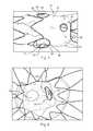
- FIG. 5shows another fenestrated prosthesis having concave (internal) pivotable fenestrations.
- FIG. 6is an enlarged perspective view of the pivotable fenestration shown FIG. 5 .
- FIG. 7shows a fenestrated prosthesis having imageable markers and reinforcement frames.
- FIG. 8is another partial and internal view of an internal pivotable fenestration.
- FIG. 9is a partial, cross-sectional view of a portion of a prosthesis having a pivotable fenestration.
- FIG. 10shows an interior view of a pivotable fenestration where the fenestration is disposed within the lumen of the prosthesis.
- FIG. 11shows an exterior view of a pivotable fenestration where the fenestration is disposed within the lumen of the prosthesis.
- FIG. 12is a prosthesis having a protrusion of graft material to form a fenestration and an extension.
- FIG. 13is a fenestrated prosthesis that has been deployed within a diseased vessel, such as the aorta, where branch vessel prostheses are deployed within the branch vessels.
- FIG. 14shows a branch vessel prosthesis deployed in a secondary branch vessel, where the branch vessel prosthesis is deployed in a right branch vessel positioned lower than its corresponding left branch vessel.
- FIG. 15shows a branch vessel prosthesis deployed in a secondary branch vessel, where the branch vessel prosthesis is deployed in a right branch vessel positioned higher than its corresponding left branch vessel.
- FIG. 16shows an alternative fenestrated prosthesis having pivoting fenestrations.
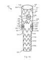
- FIG. 17shows an alternative embodiment of a prosthesis having a pivotable fenestration.
- the present disclosurerelates to an endoluminal prosthesis, such as a stent graft that includes one or more fenestrations to accommodate endovascular disease, such as an aneurysm in cases where one or more side branches is involved, and a side branch prosthesis is deployed within the fenestration to permit fluid flow from the endoluminal prosthesis into the branch vessel.
- the prosthesisincludes fenestrations that pivot as needed to accommodate the dynamic geometry of the aortic branches.
- one or more pivotable fenestrations provided on a prosthesislie outside the surface plane of the body of the prosthesis and will allow a branch vessel stent, graft or stent-graft that has been placed in the fenestration to pivot into a variety of orientations required to meet and seal the branch vessel device in the branch vessel.
- the orientation of the fenestrationsmay dynamically change over time as needed by changing anatomy.
- distalmeans a location or direction that is, or a portion of a device that when implanted is further downstream in the direction of or with respect to blood flow.
- proximalmeans a location or direction that is, or a portion of a device that when implanted is further upstream in the direction of or with respect to blood flow.
- fenestrationmeans an opening provided through a surface of a prosthesis from the interior of the prosthesis to the exterior of the prosthesis and may have a variety of geometries, including circular, semi-circular, oval, oblong, as well as other geometries.
- biocompatiblerefers to a material that is substantially non-toxic in the in vivo environment of its intended use, and that is not substantially rejected by the patient's physiological system (i.e., is non-antigenic).
- biocompatible materials from which textile graft material can be formedinclude, without limitation, polyesters, such as polyethylene terephthalate, fluorinated polymers, such as polytetrafluoroethylene (PTFE) and fibers of expanded PTFE, and polyurethanes.
- PTFEpolytetrafluoroethylene
- materials that are not inherently biocompatiblemay be subjected to surface modifications in order to render the materials biocompatible.
- Examples of surface modificationsinclude graft polymerization of biocompatible polymers on the material's surface, coating of the surface with a crosslinked biocompatible polymer, chemical modification with biocompatible functional groups, and immobilization of a compatibilizing agent such as heparin or other biocompatible substances.
- a compatibilizing agentsuch as heparin or other biocompatible substances.
- any fibrous material having sufficient strength to survive in the in vivo environmentmay be used to form a textile graft, provided the final textile is biocompatible.
- Fibers suitable for making textile graftsinclude polyethylene, polypropylene, polyaramids, polyacrylonitrile, nylon, and cellulose, in addition to the polyesters, fluorinated polymers, and polyurethanes as listed above.
- bioremodelable materialsmay also be used singly or in combination with the aforementioned polymer materials.
- the textilemay be made of one or more polymers that do not require treatment or modification to be biocompatible.
- the graftmay be constructed from woven multifilament polyester, for example and without limitation, DacronTM, produced by DuPONT. DacronTM is known to be sufficiently biologically inert, non-biodegradable, and durable to permit safe insertion inside the human body.
- prosthesismeans any device for insertion or implantation into or replacement for a body part or function of that body part. It may also mean a device that enhances or adds functionality to a physiological system.
- prosthesismay include, for example and without limitation, a stent, stent-graft, filter, valve, balloon, embolization coil, and the like.
- tubularrefers to the general shape of an endoluminal device which allows the module to carry fluid along a distance or fit within a tubular structure such as an artery.
- Tubular prosthetic devicesinclude single, branched, and bifurcated devices.
- Tubularmay refer to any shape including, but not limited to, tapered, cylindrical, curvilinear, or any combination thereof.
- a tubular devicemay have a cross-sectional shape that is, circular, substantially circular or the like. However, it should be understood that the cross-sectional shape is not limited thereto, and other shapes, such as, for example, hexagonal, pentagonal, octagonal, or the like are contemplated.
- endoluminalrefers to or describes objects that can be placed inside a lumen or a body passageway in a human or animal body.
- a lumen or a body passagewaycan be an existing lumen or a lumen created by surgical intervention.
- the terms “lumen” or “body passageway”are intended to have a broad meaning and encompass any duct (e.g., natural or iatrogenic) within the human body and can include a member selected from the group comprising: blood vessels, respiratory ducts, gastrointestinal ducts, and the like.
- Endoluminal deviceor “endoluminal prosthesis” thus describes devices that can be placed inside one of these lumens.
- graftor “graft material” describes an object, device, or structure that is joined to or that is capable of being joined to or implanted in or against a body part to enhance, repair, or replace a portion or a function of that body part.
- a graft by itself or with the addition of other elements, such as structural components,may comprise an endoluminal prosthesis.
- the graftmay be comprised of a single material, a blend of materials, a weave, a laminate, or a composite of two or more materials.
- the graftmay be constructed from natural or organic materials, for example and without limitation, a biological scaffold or bioremodelable material, such as small intestine submucosa (“SIS”), which is commercially available by Cook Biotech, West Lafayette, Ind.
- SISsmall intestine submucosa
- the graftmay also be constructed from a synthetic, for example and without limitation, a polymer.
- the graftmay be formed from a single layer or multiple layers of material. In embodiments employing a plurality of layers of material, the layers may remain separate, or may be attached to each other through a secondary process such as sintering, curing, adhesives, and sutures or the like.
- stentmeans any device or structure that adds rigidity, expansion force or support to a prosthesis.
- a stentis used to obtain and maintain the patency of the body passageway while maintaining the integrity of the passageway. Also, the stent may be used to form a seal.
- the stentmay be located on the exterior of the device, the interior of the device, or both.
- a stentmay be self-expanding, balloon-expandable or may have characteristics of both.
- the stentsmay be comprised of a metallic material selected from stainless steel, silver, platinum, palladium, gold, titanium, tantalum, iridium, tungsten, cobalt, chromium, cobalt-chromium alloy 1058, cobalt-based 35N alloy, nickel-based alloy 625, a molybdenum alloy, a molybdenum alloy including about 0.4% to about 0.8% of lanthanum oxide (Li 2 O 3 ), and a nickel-titanium alloy, such as nitinol, or other suitable materials as known in the art.
- the stentsmay be made of a wire, or may be laser or cannula cut, or manufactured by other known methods.
- fusedrefers to a length of a continuous thread or strand of one or more filaments or fibers, with or without twist, suitable for weaving, knitting or otherwise intertwining to form a textile fabric.
- branch vesselrefers to a vessel that branches off from a main vessel.
- examplesare the celiac and renal arteries which are branch vessels to the aorta (i.e., the main vessel in this context).
- the hypogastric arteryis a branch vessel to the common iliac, which is a main vessel in this context.
- branch vesseland “main vessel” are relative terms.
- Longitudinallyrefers to a direction, position or length substantially parallel with a longitudinal axis of a reference, and is the length-wise component of the helical orientation.
- Circumferentiallyrefers to a direction, position, or length that encircles a longitudinal axis of a reference.
- the term “circumferential”is not restricted to a full 360° circumferential turn or to a constant radius.
- patientrefers to any animal, especially humans.
- FIGS. 1-8show a fenestrated prosthesis 10 , here a stent graft, having a tubular body and comprising a biocompatible material, having one or more fenestrations 12 pivotable in any direction away from an axis perpendicular to a longitudinal axis of the prosthesis.
- the pivotable fenestrations 12have a diameter extending from a sidewall of the graft.
- the pivotable fenestrations 12include a first, inner perimeter 26 surrounding the fenestration 12 having a diameter, a band 28 of flexible material attached to and surrounding the first perimeter 26 , and a second, outer perimeter 30 attached to and surrounding the band 28 of flexible material.
- the band 28 of materialhas a first diameter that is substantially the same as the diameter of the first perimeter 26 , and a second diameter substantially the same as the second perimeter 30 .
- the diameter of the band of materialdecreases in a direction away from the surface 20 of the graft 14 from the second perimeter to the first perimeter.
- the band of flexible materialmay include a flexible frame 48 .
- the fenestrated prosthesis 10is intended for placement in the abdominal aorta and to accommodate vessels that branch from the aorta, for example, the renal arteries, and into which a branch vessel prosthesis may be placed.
- the fenestrated prosthesis 10is not limited for use in the abdominal aorta but may be used in other vessels of the body from which other vessels branch, such as the ascending thoracic aorta, the descending thoracic aorta, as well as other body vessels.
- FIG. 1shows a perspective view of a prosthesis 10 that is a stent graft.
- the prosthesis 10includes graft material 14 associated with one or more stents 16 .
- the prosthesis 10has a proximal end 22 , a distal end 24 , and a lumen 18 extending through the prosthesis 10 to permit passage of blood flow from the proximal end 22 to the distal end 24 .
- the stents 16may be placed on the external surface 20 and/or internal surface 21 of the graft material 14 .
- the prosthesis 10such as that shown in FIG. 1 , has external body stents 16 a , 16 b , and 16 c , and at least one internal stent 16 d .
- the internal stent 16 dmay be a sealing stent and placed at or near the proximal end 22 of the prosthesis 10 to seal the prosthesis 10 at the proximal end 22 to the walls of a blood vessel into which it has been placed. Additionally, or alternatively, depending on the location of the prosthesis 10 or a particular need, a sealing stent 16 d may be placed at either or both the proximal and distal ends 22 , 24 of prosthesis 10 .
- the prosthesis 10also may include an attachment mechanism, for example, an attachment stent 42 , at either or both ends of the prosthesis 10 , to further secure the prosthesis 10 within the body vessel and prevent migration of the prosthesis 10 .
- the prosthesis 10has several openings or fenestrations that extend from the internal surface 21 to the external surface 20 of the graft material 14 .
- the prosthesis 10 of FIG. 1has two pivotable fenestrations 12 , at least one non-pivotable fenestration 38 , and a scallop 40 .
- the scallop 40is placed at the proximal end 22 of the prosthesis 10 .
- FIGS. 1-8show various aspects and views of the prosthesis 10 having pivotable fenestrations 12 .
- Pivotable fenestrations 12have an inner perimeter 26 surrounding the fenestration 12 , a band 28 surrounding the inner perimeter 26 , and an outer perimeter 30 surrounding the band 28 .
- the outer perimeter 30 diameteris greater than the band 28 diameter and the inner perimeter diameter 26 .
- the inner perimeter 26 , the band 28 and the outer perimeter 30would be substantially concentric with one another if they were in the same plane, for example the surface plane of the graft.
- the inner perimeter 26 , the band 28 and the outer perimeter 30may form a hemispherical shape, resembling a dome, or a frustoconical cone extending from the surface of the graft material 14 .
- the fenestration 12is provided at the peak or top of the hemispherical shape or extension.
- the band 28may comprise a tapered, flexible tube extending from the outer perimeter 30 and the inner diameter 26 .
- Stents 16may be, for example zig zag stents, also known has Z-stents, that comprise a series of struts 32 , 34 connected by apices 36 , although the type of stent used is not so limited. When Z-stents are used, a portion of the outer perimeter 30 of one or more of the fenestrations 12 may lie between adjacent struts 32 , 34 of one of the stents 16 .
- the stents 16may be either self-expanding or balloon expandable. Preferably, they are self-expanding. However, a combination of self-expanding and balloon expandable stents also may be contemplated.
- the stents 16include struts 32 , 34 that are spaced apart from each other.
- the strut spacingis measured from bend-to-bend (or apex to apex 36 ).
- Stent amplitude, spacing and staggerare preferably optimized for each prosthesis design.
- the apices or bends 36 of the struts 32 , 34may be staggered for minimal contact with each other.
- the stents 16 a , 16 b , 16 care positioned adjacent each other and the apices 36 of each row are in circumferential alignment with the bends of longitudinally adjacent rows.
- every bend 36 of each rowmay be in substantial circumferential alignment with the bends 36 of longitudinally adjacent rows.
- the pivotable fenestrations 12may be located within the lumen 18 of the prosthesis 10 or extending from the exterior of the prosthesis 10 .
- the pivotable fenestrations 12may be said to be concave, relative to the external surface 20 of the graft material 14 .
- the pivotable fenestrations 12may be said to be convex, relative to the external surface 20 of the graft material 14 .
- FIG. 1shows the pivotable fenestrations 12 located internal to the prosthesis 10 , that is, they lie within the lumen 18 of the prosthesis 10 .
- the pivotable fenestrations 12reside substantially on one side of the prosthesis 10 and are adjacent to one another.
- the pivotable fenestrations 12are positioned to align with, for example, the renal arteries.
- the one or more pivotable fenestrations 12may be positioned to align with other branch arteries throughout a diseased vasculature. Additional fenestrations and scallops as disclosed here may also be included.
- FIG. 2which is a partial internal view of the prosthesis 10 of FIG. 1 , shows a view of the prosthesis 10 looking into the lumen 18 of the prosthesis 10 from the proximal end 22 .
- pivotable fenestrations 12extend or protrude into the lumen 18 .
- Pivotable fenestrations 12have an inner perimeter 26 , a band 28 , and an outer perimeter 30 .
- the outer perimeter 30lies substantially flush (in the same plane) with the graft material 14 , and the band 28 and the outer perimeter 30 form a hemispherical shape, such as a dome or frustoconical cone extending into the lumen 18 .
- both the inner and outer perimeters 26 , 30are shown as substantially circular, they may be oval, oblong or some other desired geometric shape.
- FIGS. 3 and 4show an aspect of a prosthesis 10 having externally extending pivotable fenestrations 12 .
- FIG. 3shows a partial view of a prosthesis 10 having two externally extending pivotable fenestrations 12 extending from opposite sides of the prosthesis 10 .
- the fenestrations 12have an inner perimeter 26 surrounding the fenestration, a band 28 of material surrounding the inner perimeter 26 , and an outer perimeter 30 surrounding the band 28 of material.
- FIG. 4which is a partial internal view of the prosthesis 10 of FIG. 3 , shows a view of the prosthesis 10 of FIG. 3 , looking into the lumen 18 of the prosthesis 10 from the proximal end 22 .
- pivotable fenestrations 12extend or protrude away from the external surface 20 of the graft material 14 .
- the outer perimeter 30lies substantially flush (in the same plane) with the graft material 14 , and the band 28 and the outer perimeter 30 form a hemispherical shape, such as a dome, or frustoconical cone extending into the lumen 18 .
- FIGS. 5 and 6show further aspects of a fenestrated prosthesis 10 having at least one pivotable fenestration 12 .
- FIG. 5shows a prosthesis 10 that is a stent graft.
- the prosthesisincludes a proximal end 22 , a distal end 24 , a graft material 14 associated with a series of external stents 16 .
- the prosthesis 10further has an internal sealing stent 16 d , and attachment stent 42 , and a pivotable fenestration 12 .
- FIG. 6shows a partial close up view of the fenestration of FIG. 5 .
- the pivotable fenestration 12 shownis an external fenestration 12 and has an inner perimeter 26 surrounding the fenestration 12 , a band 28 of material surrounding the inner perimeter 26 , and an outer perimeter 30 surrounding the band 28 . As shown, a portion of the outer perimeter 30 lies between struts 32 , 34 of the proximal most stent 16 .
- the prosthesis 10includes a non-pivoting fenestration 38 and a scallop 40 at the proximal end 22 .
- imageable markers 35which may be viewed during and after placement of the prosthesis 10 may be placed at various locations on the prosthesis 10 to identify certain aspects of the prosthesis and their location during the implantation procedure and facilitate correct placement of the fenestrations 12 , 38 , scallop 40 , the ends of the prosthesis and the like.
- markers 35may be placed about the circumference of the outer perimeter 30 .
- the markers 35may be, for example, sewn or sutured to the graft material 14 , as shown, or may be woven into the graft (not shown).
- the markers 35also may be placed on the struts of one or more stents, for example, radiopaque marker tubes may be placed about one or more struts of the stent to indicate various areas of the stent graft. As shown, the markers 35 may be gold, however, any material that may be imaged by way of angiography, fluoroscopy, 3D imaging, MRI, or the like, may be suitable.
- the fenestrations 12 , 38 and the scallop 40may include a reinforcement frame 44 a , 44 b , 44 c , 44 d which may be sutured or otherwise attached to the graft 14 .
- a reinforcement frame 44 amay be positioned about the outer perimeter 30 .
- a reinforcement frame 44 bmay be positioned about the inner perimeter 26 .
- a reinforcement frame 44 cmay be provided about the non-pivoting fenestration 38
- reinforcement frame 44 dmay be provided about the perimeter of the scallop 40 .
- the reinforcement frames 44 a , 44 b , 44 c , 44 dmay be rings.
- the reinforcement frames 44 a , 44 b , 44 c , 44 dare a wire that is sutured about the fenestration 12 , 38 , or scallop 40 , to reinforce the fenestration or scallop.
- the reinforcement frames 44 a , 44 b , 44 c , 44 dmay be made of any suitable material.
- One preferred materialis a superelastic or shape memory material, such as nitinol.
- the reinforcement frames 44 a , 44 b , 44 c , 44 dmay be made of radiopaque or other imageable material.
- the reinforcement frames 44 a , 44 b , 44 c , 44 dmay be solid rings, or may be a wire that is looped about itself into a ring with unattached ends such that the ring may be expanded or contracted in diameter.
- Suitable framesare disclosed in U.S. patent application Ser. No. 10/962,632, filed Oct. 12, 2004, hereby incorporated by reference.
- FIG. 8is another partial and internal view of a fenestrated prosthesis 10 having two internal pivotable fenestrations 12 . As shown in this aspect, a dome-like projection or frustoconical extension is formed within the prosthesis 10 .
- a flexible frame 48may be disposed about or within the band 28 .
- inner perimeter 26 , band 28 , and outer perimeter 30surround the pivotable fenestration 12 to create a hemisphere shaped or frustoconical extension or protrusion.
- the outer perimeter 30may be affixed to the graft material 14 by any attachment method including suturing circumferentially about an aperture disposed through graft material 14 .
- the band 28may be comprised of the same or different biocompatible material as the graft material 14 .
- the second biocompatible materialmay have greater pliability than the first biocompatible graft material used for the tubular graft body.
- the band 28is sufficiently flexible to permit the fenestration 12 to move such that a branch stent disposed in the fenestration 12 may be oriented upwardly, downwardly, laterally, diagonally and the like.
- the bandhas up to about 180 degrees of freedom of movement relative to the surface plane of the prosthesis 10 . Accordingly, the pivotable fenestration 12 allows the prosthesis 10 to be used with a variety of patients, due to its ability to adapt to the variance in the positioning of the diseased branch vessels.
- a body branch vesselis or becomes offset longitudinally or axially from a pivoting fenestration 12
- the pivoting fenestration 12will pivot the branch vessel prosthesis in the necessary direction and to the necessary degree to maintain the branch vessel prosthesis in place in the branch vessel.
- FIG. 9shows a partial, cross-sectional view of a portion of prosthesis 10 having a pivotable fenestration 12 , inner perimeter 26 surrounding fenestration 12 , band 28 surrounding inner perimeter 26 and outer perimeter 30 surrounding band 28 .
- the band 28may be tapered such that the diameter decreases throughout its depth ⁇ .
- the depth ⁇may be determined on the amount of movement required for the pivotable fenestration 12 during use and the ability to cannulate the targeted branch vessel. As the depth ⁇ decreases, the amount of the second biocompatible material used for the band 28 must also decrease, which limits the range of motion of the pivotable fenestration 12 . Furthermore, the depth ⁇ must be large enough in order to cannulate the targeted branch vessel.
- the depth ⁇may range from 3 to 10 mm, and preferably is about 6 mm.
- inner perimeter 26has a diameter ⁇ that is smaller than the diameter ⁇ of outer perimeter 30 .
- the diameter ⁇ of the inner perimeter 26may be determined based on the average size of the targeted branch vessel.
- the prosthesis 10may be used to repair a diseased renal artery. Accordingly, the average diameter of the inner perimeter 26 may be based on the average of the diameter of the openings to the renal arteries, or about 6 mm.
- the diameter ⁇ of the outer perimeter 30may be determined based on the desired amount of movement and the desired patency of the prosthesis 10 . As the diameter ⁇ of the outer perimeter 30 changes, the range of motion also changes. As the diameter ⁇ of the outer perimeter 30 decreases, the range of motion also decreases. Additionally, the diameter ⁇ of the outer perimeter 30 must be sized to prevent interference with circumferentially adjacent struts 32 , 34 of the stents 16 . Hence, the diameter ⁇ of the outer perimeter 30 may be at most about 15 mm in order to accommodate stents 16 .
- the diameters ⁇ and ⁇ combined with depth ⁇provide the requisite amount of surface area for the pivotable fenestration 12 to pivot during deployment of a secondary branch prosthesis into the fenestration 12 based on dynamic changes to the anatomy.
- FIGS. 10 and 11show an internal view and an external view, respectively, of a pivotable fenestration 12 in an aspect where the fenestration is disposed within the lumen 18 of the prosthesis 10 .
- FIG. 10shows pivotable fenestration 12 , inner perimeter 26 , band 28 , outer perimeter 30 .
- a reinforcement frame 44 ais positioned about the outer perimeter 30 .
- a reinforcement frame 44 bis positioned about the inner perimeter 26 .
- the reinforcement frames 44 a and 44 bmay be affixed to the outer perimeter 30 and inner perimeter 26 by sewing. Markers 35 are placed around the inner perimeter 26 in order to facilitate proper placement and alignment of a branch vessel prosthesis and the pivotable fenestration 12 .
- the band 28may be provided with a flexible frame 48 .
- the flexible frame 48provides support to the band 28 and helps to maintain the overall structure of the band 28 upon deployment within the diseased vessel.
- the flexible frame 48also helps to maintain the patency of the pivotable fenestration 12 .
- the flexible frame 48allows the band 28 of material to reverse orientation and independently move between an interior surface of the prosthesis 10 and an exterior surface of the prosthesis 10 while the device is being deployed.
- a physicianmay alter the orientation of the band 28 during deployment of the prosthesis 10 through the use of endoluminal devices, such as a guidewire catheter.
- the structure of the flexible frame 48also prevents the pivotable fenestration 12 from everting or inverting (depending on the initial configuration) once the prosthesis 10 is deployed within the diseased vessel.
- the flexible frame 48may be positioned on the band 28 either on the interior or exterior surface of the band 28 . In this particular aspect, the flexible frame 48 is positioned on the interior surface of the band 28 .
- the flexible frame 48comprises a continuous wire formed into a plurality of support units 50 having a generally undulating shape comprising straightened struts 52 interconnected by outwardly facing apices or bends 54 .
- the number of support units 50may range from about 2 support units to about 10 support units.
- the flexible frame 48has three support units 50 .
- the outwardly facing apices 54may abut or connect to the reinforcing frame 44 a of the outer perimeter 30 .
- the outwardly facing apicesmay be, for example, sewn or sutured to reinforcing frame 44 a .
- the frame 48may be bent to form a plurality of loops 56 a , 56 b , 56 c , 56 d . Loops 56 a , 56 b , 56 c are positioned in the troughs of the apices 54 of adjacent support units 50 .
- Each loop 56 a , 56 b , 56 cmay abut or connect to the reinforcing frame 44 b of the inner perimeter 26 .
- the loops 56 a , 56 b , 56 cmay be, for example, sewn or sutured to reinforcing frame 44 b .
- a loop 56 dmay be positioned within an apex 54 of a support unit 50 .
- Other aspectsmay comprise other configurations for the flexible frame 48 , including, but not limited to, spirals, may be suitable.
- the flexible frame 48may be heat set into the desired configuration prior to attachment to band 28 .
- the flexible frame 48may be comprised of an elastic or super elastic material, for example and without limitation, nitinol.
- FIG. 11shows an exterior view of a pivotable fenestration 12 where the fenestration is disposed within the lumen 18 of the prosthesis.
- the pivotable fenestration 12has an inner perimeter 26 surrounding the fenestration 12 , a band 28 surrounding the inner perimeter 26 , and an outer perimeter 30 surrounding the band 28 .
- a reinforcement frame 44 ais positioned about the outer perimeter 30 . Markers 35 may be sewn around the circumference of the outer perimeter 30 in order to facilitate proper placement and alignment of the pivotable fenestration 12 and the targeted branch vessel.
- FIG. 12shows an embodiment of the band 28 formed from a protrusion 58 having a bubble like configuration as shown in FIG. 12 , as described in co-pending U.S. patent application Ser. No. 12/548,120.
- the protrusion 58is integrally formed with the body of the prosthesis 10 and is comprised of a second biocompatible graft material.
- the protrusion 58may be created during the weaving process used to create the graft material 14 .
- the prosthesis 10may include, but is not limited to, weaves such as plain weaves, basket weaves, rep or rib weaves, twill weaves (e.g., straight twill, reverse twill, herringbone twill), satin weaves, and double weaves (e.g., double-width, tubular double weave, reversed double weave).
- the weavecomprises a tubular double layer weave.
- the fabricmay be woven on a table loom, a floor loom, a jacquard loom, a counterbalance loom, a jack loom, or an upright loom.
- the fabricis woven on a floor loom.
- the fabricmay have any configuration possible, but preferably has warp and weft yarns. In one aspect, both the warp yarns and the weft yarns are textile yarns.
- the number of warp yarns used while weaving the prosthesis 10is increased in the region where the protrusion 58 is desired. While the additional warp yarns are weaved into the prosthesis 10 , the number of weft yarns is kept constant. By increasing the number of warp yarns while holding the number of weft yarns constant, the second biocompatible graft material expands outwardly in the radial direction. The number of warp yarns is increased until a pre-determined diameter has been reached. Once the desired depth for the protrusion 58 is reached, the number of warp yarns introduced into the weaving apparatus is decreased until the number of warp yarns is equal to the number of weft yarns used to form the remainder of the prosthesis 10 .
- a fenestrationmay be created through the protrusion 58 by applying heat to the center of the protrusion 58 .
- Reinforcing framesmay be added about the fenestration 12 and adjacent to and surrounding the protrusion 58 to form the inner and outer perimeters 26 , 30 of the prosthesis 10 .
- a flexible frame 48may be attached to the protrusion 58 to maintain it in its desired extended configuration.
- FIG. 13depicts an exemplary prosthesis that has been deployed within a diseased vessel 70 , such as the aorta.
- the prosthesis 10comprises a tubular graft 72 having a sidewall 74 and a lumen 76 disposed longitudinally therein.
- the prosthesis 10includes a first end 78 and a second end 80 .
- the tubular graft 72includes a plurality of rows 82 a , 82 b , 82 c of expandable stents circumferentially aligned affixed to the outer surface 84 of the tubular graft 72 .
- a sealing stent 86may be affixed to the first end 78 of the tubular graft 72 within the interior surface of the graft 72 .
- the sealing stent 86may be attached to the first end 78 of the tubular graft 72 by any attaching mechanism, for example and without limitation, suturing.
- Radiopaque markers 88may be placed on the tubular graft 72 in order to assist with proper alignment of the tubular graft 72 when deployed within a patient.
- Fenestration 90may be disposed through the tubular graft 72 .
- the distal end (not shown) of the prosthesis 10may be bifurcated.
- the tubular graft 72also includes two internal pivotable fenestrations 12 that are in communication with the lumen 76 .
- the tubular graft 72may be preloaded onto a delivery device for deployment within a patient.
- the delivery deviceincludes a sheath over the tubular graft 72 to keep the tubular graft 72 in a compressed state prior to deployment.
- the delivery deviceis placed over a guide wire and after checking the appearance and orientation of the device under x-ray, guide wires for each fenestration 12 are loaded through side ports in the handle of the delivery device.
- the delivery deviceis introduced over the guide wire, and advanced until a tapered tip of the delivery device is in the femoral artery and the radiopaque markers 88 indicating the fenestrations 12 are at a level of the appropriate arteries.
- a sheathis advanced over the guide wire for each fenestration 12 through each side port on the handle of the device. Once the sheaths for the fenestrations 12 are in position, the tubular graft 72 can be advanced to its correct position and orientation for deployment. The tubular graft 72 is deployed by withdrawing the sheath covering the graft 72 over the pusher. The operator can perform angiography and adjust the placement of the tubular graft 72 if necessary.
- the sheaths for the fenestrations 12are advanced over the wires until they are at a level of the lower margin of the fenestration 12 .
- the sheaths for the fenestrations 12are punctured and a guide wire is advanced through each sheath.
- a catheteris advanced over the guide wires, and once the catheters are in the target vessels, a stiffer wire replaces the guide wire.
- the sheaths for the fenestrations 12are then advanced into the target vessels and branch vessel prostheses are advanced through the sheath and placed in the desired position.
- FIG. 13illustrates in accordance with the procedure described above branch vessel prosthesis deployed through each of the two fenestrations 12 .
- Branch vessel prostheses 92 , 94are formed from biocompatible materials and may comprise covered stents. Alternatively, they may comprise bare stents. The covered or bare stents may be either self-expanding or balloon expandable. In one aspect the branch vessel stent may have both self-expanding and balloon expandable components. For example, the branch vessel stent may have an end not shown for placement within the fenestration 12 , and thus upon deployment, may be either self-expanding or by balloon expanding. If the branch vessel stent is a covered stent, the graft material used may comprise one or more of the biocompatible materials are discussed above.
- the branch vessel prostheses 92 , 94are deployed into branch vessels 96 , 98 such as the right and left renal arteries.
- the right opening 100is not completely aligned with the right branch vessel 96 .
- the right branch vessel 96is positioned lower than the corresponding left branch vessel 98 .
- the pivotable fenestration 12provides the requisite flexibility and ability to pivot required for the branch vessel prosthesis 92 to deploy into the desired position.
- FIGS. 14 and 15show a branch vessel prosthesis 92 deployed in a secondary branch vessel in greater detail.
- the branch vessel prosthesis 92is deployed within the right branch vessel 96 , which is positioned lower than its corresponding left branch vessel 98 .
- the branch vessel prosthesis 92is deployed within the right branch vessel 102 , which is positioned higher than its corresponding left branch vessel.
- the pivotable fenestration 12allows for pivoting motion to accommodate the offset position of the right branch vessel 96 , 102 and provide access to the right branch vessel 96 , 102 through the use of a delivery device, such as a catheter.
- the branch vessel prosthesis 92may be deployed within the right branch vessel 96 , 102 .
- the branch vessel prosthesis 92may be balloon expandable or self-expandable. In this aspect, the branch vessel prosthesis 92 is balloon expandable.
- the end of the branch vessel prosthesis 92 remaining within the interior surface of the prosthesis 10may be flared in order to provide a proper seal between the fenestration 12 and the right branch vessel 96 , 102 .
- FIG. 16shows alternative aspects of a prosthesis 210 .
- FIG. 16shows a prosthesis 210 that is a stent graft.
- the prosthesis 210includes graft material 214 associated with one or more stents 216 .
- the prosthesis 210has a proximal end 222 , a distal end 224 , and a lumen 218 extending through the prosthesis 210 .
- the stents 216may be placed on the external surface 220 and/or internal surface 221 of the graft material 214 . In some embodiments, the stents may all be placed on the external surface 220 of the graft material 214 .
- the prosthesis 210such as that shown in FIG.
- the prosthesis 210may also include a sealing stent 217 positioned at the proximal end 222 of the prosthesis 210 to seal the prosthesis 210 at the proximal end 222 to the walls of the blood vessel into which it has been placed.
- a sealing stent 217may be placed at either or both the proximal and distal ends 222 , 224 of prosthesis 210 .
- the internal stent 216 fis positioned “out of phase” by about 180 degrees with longitudinally adjacent row 216 a , such that circumferentially about the surface of the graft, every other apex of the internal stent 216 f matches with every other apex of stent row 216 a .
- the internal stent 216 dmay be positioned in phase with longitudinally adjacent row 216 a , or the internal stent 216 d may be out of phase by an amount less than 180 degrees.
- the prosthesis 210also may include an attachment mechanism, for example, an attachment stent, at either or both ends 222 , 224 of the prosthesis 210 , to further secure the prosthesis 210 within the body vessel and prevent migration of the prosthesis 210 .
- the prosthesis 210has several openings or fenestrations 212 , 238 that extend from an internal surface 221 to the external surface 220 of the graft material 214 .
- the prosthesis 210 of FIG. 16has two renal pivotable fenestrations 212 a , a celiac pivotable fenestration 212 b , and a superior mesenteric artery non-pivotable fenestration 238 .
- the prosthesis 210may include all pivotable fenestrations 212 that extend from an internal surface 221 to the external surface 220 .
- Pivotable fenestrations 212have a first, inner perimeter 226 surrounding the fenestration 212 , a band of material 228 surrounding the inner perimeter 226 , and a second, outer perimeter 230 surrounding the band 228 .
- the inner perimeter 226 , the band 228 and the outer perimeter 230would be substantially concentric with one another if they were in the same plane, for example the surface plane of the graft.
- the inner perimeter 226 , the band 228 and the outer perimeter 230may form a geometric shape.
- the inner perimeter 226 , the band 228 and the outer perimeter 230may form a hemispherical shape, resembling a dome.
- pivoting fenestrations 212 amay be positioned between opposing struts of longitudinally adjacent stent rows 216 f and 216 a .
- the diameter of the inner perimeter 226may be determined based on the average size of the targeted branch vessel. In this aspect, the diameter of the inner perimeter 226 of pivotable fenestration 212 a may be based on the average of the diameter of the openings to the renal arteries, or about 6 mm.
- the diameter of the inner perimeter 226 of pivotable fenestration 212 bmay be based on the average of the opening of the celiac artery, or about 8 mm.
- the diameter of the non-pivotable fenestration 238may be based on the average of the opening of the superior mesenteric artery, or about 8 mm.
- the inner perimeter 226 , the band 228 , and the outer perimeter 230may be integral with the graft material 214 or attached separately to the graft material 214 .
- the band 228may be comprised of the same or different biocompatible material as the graft material 214 .
- the biocompatible material forming the band 228may have greater pliability than the biocompatible graft material used for the tubular graft body.
- the band 228is sufficiently flexible to permit the fenestration 212 a , 212 b to move such that a branch stent disposed in the fenestration 212 a , 212 b may be oriented upwardly, downwardly, laterally, diagonally and the like.
- the band 228 of materialmay move independently between an interior surface 221 of the prosthesis 210 and an exterior surface 220 of the prosthesis 210 while the device is being deployed.
- the band 228may be able to move up to 6 mm while the device is being deployed within a patient.
- a flexible framemay be disposed on a surface of the band 228 .
- the depth of the band 228may extend within the interior surface 221 of the prosthesis 210 or outward from the exterior surface 220 of the prosthesis 210 . The depth may be determined based on the amount of movement required for the pivotable fenestrations 212 a , 212 b during use and the ability to cannulate the targeted branch vessel.
- the pivotable fenestrations 212 a , 212 ballow the prosthesis 210 to be used with a variety of patients, due to its ability to adapt to the variance in the positioning of the branch vessels. For example, if a body branch vessel is or becomes offset longitudinally or axially from a pivoting fenestration 212 , the pivoting fenestration 212 will pivot the branch vessel prosthesis in the necessary direction and to the necessary degree to maintain the branch vessel prosthesis in place in the branch vessel.
- This embodiment of the prosthesis 212may be useful in treating Type IV thoracoabdominal aortic aneurysms that involve all four visceral branch arteries (celiac, superior mesenteric artery, and the renal arteries).
- pivotable fenestrations 212 a , 212 ballow for variation in placing the graft within a patient, while allowing for the flow of blood to continue into these arteries.
- FIG. 17shows an alternative embodiment of a prosthesis 310 .
- the prosthesis 310includes graft material 314 associated with one or more stents 316 , having a proximal end 322 , a distal end 324 , and a lumen 318 extending therethrough.
- the prosthesis 310such as that shown in FIG. 16 , has external body stents 316 a , 316 b , 316 c , 316 d , 316 e and at least one internal stent 316 f .
- the stents 316 a , 316 b , 316 c , 316 d , 316 eare positioned longitudinally adjacent to each other and the apices of each row are in circumferential alignment, or “in phase”, with the apices of longitudinally adjacent rows.
- the internal stent 316 fis positioned “out of phase” by about 180 degrees with longitudinally adjacent row 316 a , such that circumferentially about the surface of the graft, every other apex of the internal stent 316 f matches with every other apex of stent row 316 a .
- a sealing stent 317is positioned at the proximal end 322 of the prosthesis 310 to seal the prosthesis 310 at the proximal end 322 to the walls of the blood vessel into which it has been placed.
- the prosthesis 310has several openings or fenestrations 312 that extend from an internal surface 321 to the external surface 320 of the graft material 314 .
- the prosthesis 310 of FIG. 17has two renal pivotable fenestrations 312 a , a celiac pivotable fenestration 312 b , and a superior mesenteric artery pivotable fenestration 312 c .
- Pivotable fenestrations 312 a , 312 b , 312 chave a first, inner perimeter 226 surrounding the fenestration 312 , a band of material 228 surrounding the inner perimeter 326 , and a second, outer perimeter 330 surrounding the band 328 .
- the inner perimeter 326 , the band 328 and the outer perimeter 330would be substantially concentric with one another if they were in the same plane, for example the surface plane of the graft.
- the inner perimeter 326 , the band 328 and the outer perimeter 330form a hemispherical shape.
- the diameter of the inner perimeter 326may be determined based on the average size of the targeted branch vessel. In this aspect, the diameter of the inner perimeter 326 of pivotable fenestration 312 a may be based on the average of the diameter of the openings to the renal arteries, or about 6 mm.
- the diameter of the inner perimeter 326 of pivotable fenestration 312 bmay be based on the average of the opening of the celiac artery, or about 8 mm.
- the diameter of the fenestration 312 cmay be based on the average of the opening of the superior mesenteric artery, or about 8 mm.
Landscapes
- Health & Medical Sciences (AREA)
- Engineering & Computer Science (AREA)
- Biomedical Technology (AREA)
- Heart & Thoracic Surgery (AREA)
- Oral & Maxillofacial Surgery (AREA)
- Transplantation (AREA)
- Cardiology (AREA)
- Vascular Medicine (AREA)
- Life Sciences & Earth Sciences (AREA)
- Animal Behavior & Ethology (AREA)
- General Health & Medical Sciences (AREA)
- Public Health (AREA)
- Veterinary Medicine (AREA)
- Pulmonology (AREA)
- Gastroenterology & Hepatology (AREA)
- Prostheses (AREA)
Abstract
Description
Claims (22)
Priority Applications (8)
| Application Number | Priority Date | Filing Date | Title |
|---|---|---|---|
| US13/729,933US8870939B2 (en) | 2010-08-21 | 2012-12-28 | Prosthesis having pivoting fenestration |
| CN201310682000.XACN103908356A (en) | 2012-12-28 | 2013-12-12 | Prosthesis having pivoting fenestration |
| AU2013273687AAU2013273687B2 (en) | 2012-12-28 | 2013-12-18 | Prosthesis having pivoting fenestration |
| EP13275329.4AEP2749250B1 (en) | 2012-12-28 | 2013-12-20 | Endoluminal prosthesis |
| JP2013269197AJP2014128670A (en) | 2012-12-28 | 2013-12-26 | Prosthesis having pivoting fenestration |
| US14/494,809US9468544B2 (en) | 2010-08-21 | 2014-09-24 | Prosthesis having pivoting fenestration |
| US15/279,809US9808334B2 (en) | 2010-08-21 | 2016-09-29 | Prothesis having pivoting fenestration |
| US15/723,555US10159560B2 (en) | 2010-08-21 | 2017-10-03 | Prosthesis having pivoting fenestration |
Applications Claiming Priority (3)
| Application Number | Priority Date | Filing Date | Title |
|---|---|---|---|
| US37581510P | 2010-08-21 | 2010-08-21 | |
| US13/213,349US8795349B2 (en) | 2010-08-21 | 2011-08-19 | Prosthesis having pivoting fenestration |
| US13/729,933US8870939B2 (en) | 2010-08-21 | 2012-12-28 | Prosthesis having pivoting fenestration |
Related Parent Applications (1)
| Application Number | Title | Priority Date | Filing Date |
|---|---|---|---|
| US13/213,349Continuation-In-PartUS8795349B2 (en) | 2010-08-21 | 2011-08-19 | Prosthesis having pivoting fenestration |
Related Child Applications (1)
| Application Number | Title | Priority Date | Filing Date |
|---|---|---|---|
| US14/494,809ContinuationUS9468544B2 (en) | 2010-08-21 | 2014-09-24 | Prosthesis having pivoting fenestration |
Publications (2)
| Publication Number | Publication Date |
|---|---|
| US20130116775A1 US20130116775A1 (en) | 2013-05-09 |
| US8870939B2true US8870939B2 (en) | 2014-10-28 |
Family
ID=48224230
Family Applications (4)
| Application Number | Title | Priority Date | Filing Date |
|---|---|---|---|
| US13/729,933ActiveUS8870939B2 (en) | 2010-08-21 | 2012-12-28 | Prosthesis having pivoting fenestration |
| US14/494,809Active2031-08-24US9468544B2 (en) | 2010-08-21 | 2014-09-24 | Prosthesis having pivoting fenestration |
| US15/279,809ActiveUS9808334B2 (en) | 2010-08-21 | 2016-09-29 | Prothesis having pivoting fenestration |
| US15/723,555ActiveUS10159560B2 (en) | 2010-08-21 | 2017-10-03 | Prosthesis having pivoting fenestration |
Family Applications After (3)
| Application Number | Title | Priority Date | Filing Date |
|---|---|---|---|
| US14/494,809Active2031-08-24US9468544B2 (en) | 2010-08-21 | 2014-09-24 | Prosthesis having pivoting fenestration |
| US15/279,809ActiveUS9808334B2 (en) | 2010-08-21 | 2016-09-29 | Prothesis having pivoting fenestration |
| US15/723,555ActiveUS10159560B2 (en) | 2010-08-21 | 2017-10-03 | Prosthesis having pivoting fenestration |
Country Status (1)
| Country | Link |
|---|---|
| US (4) | US8870939B2 (en) |
Cited By (15)
| Publication number | Priority date | Publication date | Assignee | Title |
|---|---|---|---|---|
| US9592112B2 (en) | 2011-11-16 | 2017-03-14 | Bolton Medical, Inc. | Device and method for aortic branched vessel repair |
| EP3272314A1 (en) | 2016-07-21 | 2018-01-24 | Cook Medical Technologies LLC | Tapered body aaa graft |
| US9956101B2 (en) | 2014-12-04 | 2018-05-01 | Trivascular, Inc. | Internal iliac preservation devices and methods |
| US10390932B2 (en) | 2016-04-05 | 2019-08-27 | Bolton Medical, Inc. | Stent graft with internal tunnels and fenestrations and methods of use |
| US10433990B2 (en) | 2014-12-23 | 2019-10-08 | Cook Medical Technologies Llc | Introducer with side opening |
| US10524893B2 (en) | 2014-09-23 | 2020-01-07 | Bolton Medical, Inc. | Vascular repair devices and methods of use |
| US10722342B2 (en) | 2011-04-28 | 2020-07-28 | The Cleveland Clinic Foundation | Endoluminal prosthesis having multiple branches or fenestrations and methods of deployment |
| US11096810B2 (en) | 2017-11-29 | 2021-08-24 | Cook Medical Technologies Llc | Preloaded pusher tip for endografts |
| US20220039939A1 (en)* | 2018-09-27 | 2022-02-10 | Kawasumi Laboratories, Inc. | Stent graft |
| US11304832B2 (en)* | 2018-04-23 | 2022-04-19 | Washington University | Fenestrated stent system and method of use |
| US11395750B2 (en) | 2016-05-25 | 2022-07-26 | Bolton Medical, Inc. | Stent grafts and methods of use for treating aneurysms |
| US11439496B2 (en)* | 2017-10-20 | 2022-09-13 | SB-Kawasumi Laboratories, Inc. | Tubular therapeutic implement, tubular therapeutic implement set, and device for indwelling tubular therapeutic implement |
| US11446168B2 (en) | 2017-04-25 | 2022-09-20 | Cook Medical Technologies Llc | Prosthesis with side branch and method of making the same |
| US11446167B2 (en) | 2011-11-11 | 2022-09-20 | Bolton Medical, Inc. | Universal endovascular grafts |
| US20240058114A1 (en)* | 2017-02-24 | 2024-02-22 | Bolton Medical, Inc. | Vascular prosthesis with crimped adapter and methods of use |
Families Citing this family (42)
| Publication number | Priority date | Publication date | Assignee | Title |
|---|---|---|---|---|
| ATE392865T1 (en)* | 2003-10-10 | 2008-05-15 | Cook William A Australia | STENT IMPLANTS WITH WINDOWS |
| CN102740807B (en) | 2009-11-30 | 2015-11-25 | 恩多斯潘有限公司 | Multi-component stent-graft system for implantation into vessels with multiple branches |
| EP2509535B1 (en)* | 2009-12-08 | 2016-12-07 | Endospan Ltd | Endovascular stent-graft system with fenestrated and crossing stent-grafts |
| US9254209B2 (en) | 2011-07-07 | 2016-02-09 | Endospan Ltd. | Stent fixation with reduced plastic deformation |
| FR2984112B1 (en)* | 2011-12-15 | 2013-12-06 | Assist Publ Hopitaux De Paris | ENDOVASCULAR PROSTHESIS |
| US9811613B2 (en) | 2012-05-01 | 2017-11-07 | University Of Washington Through Its Center For Commercialization | Fenestration template for endovascular repair of aortic aneurysms |
| WO2013171730A1 (en) | 2012-05-15 | 2013-11-21 | Endospan Ltd. | Stent-graft with fixation elements that are radially confined for delivery |
| US9993360B2 (en) | 2013-01-08 | 2018-06-12 | Endospan Ltd. | Minimization of stent-graft migration during implantation |
| US9668892B2 (en) | 2013-03-11 | 2017-06-06 | Endospan Ltd. | Multi-component stent-graft system for aortic dissections |
| US9545324B2 (en) | 2013-03-13 | 2017-01-17 | Cook Medical Technologies Llc | Pre-loaded iliac branch device and methods of deployment |
| CN105407836B (en)* | 2013-05-23 | 2018-10-02 | 恩都思潘有限公司 | Aorta ascendens holder implanting body system |
| WO2015075708A1 (en) | 2013-11-19 | 2015-05-28 | Endospan Ltd. | Stent system with radial-expansion locking |
| CN104116577B (en)* | 2014-06-27 | 2017-07-14 | 先健科技(深圳)有限公司 | Branch type overlay film frame |
| US10959826B2 (en) | 2014-10-16 | 2021-03-30 | Cook Medical Technology LLC | Support structure for scalloped grafts |
| CN106029005B (en) | 2014-12-18 | 2018-01-19 | 恩都思潘有限公司 | The Endovascular stent-graft of horizontal conduit with tired resistance |
| US20160324670A1 (en)* | 2015-05-08 | 2016-11-10 | Dean Jared Yamaguchi | Branched Stent Grafts And Stent Graft Delivery System And Methods |
| BR102015011376B1 (en)* | 2015-05-18 | 2023-04-04 | Murilo Pundek Rocha | IMPLANTABLE ARTIFICIAL BRONCHI |
| US9700443B2 (en) | 2015-06-12 | 2017-07-11 | Abbott Cardiovascular Systems Inc. | Methods for attaching a radiopaque marker to a scaffold |
| US10368977B2 (en)* | 2015-12-29 | 2019-08-06 | Cook Medical Technologies Llc | Endograft with at least two branch portions |
| EP3903732B1 (en)* | 2016-06-13 | 2025-07-30 | Bolton Medical, Inc. | Devices for reinforcing fenestrations in prosthetic implants |
| US10327935B2 (en)* | 2016-07-21 | 2019-06-25 | Cook Medical Technologies Llc | Stent graft with internal constraining mechanism |
| AU2017306141A1 (en) | 2016-08-02 | 2019-03-07 | Aortica Corporation | Systems, devices, and methods for coupling a prosthetic implant to a fenestrated body |
| WO2018156850A1 (en) | 2017-02-24 | 2018-08-30 | Bolton Medical, Inc. | Stent graft with fenestration lock |
| ES2954897T3 (en) | 2017-02-24 | 2023-11-27 | Bolton Medical Inc | Constrained Wrap Stent Graft Delivery System |
| WO2018156851A1 (en) | 2017-02-24 | 2018-08-30 | Bolton Medical, Inc. | Vascular prosthesis with moveable fenestration |
| EP3534837A1 (en) | 2017-02-24 | 2019-09-11 | Bolton Medical, Inc. | Constrainable stent graft, delivery system and methods of use |
| WO2018156849A1 (en) | 2017-02-24 | 2018-08-30 | Bolton Medical, Inc. | Vascular prosthesis with fenestration ring and methods of use |
| EP3932373B1 (en) | 2017-02-24 | 2022-12-21 | Bolton Medical, Inc. | Delivery system for radially constricting a stent graft |
| WO2018156847A1 (en) | 2017-02-24 | 2018-08-30 | Bolton Medical, Inc. | Delivery system and method to radially constrict a stent graft |
| ES2863978T3 (en) | 2017-02-24 | 2021-10-13 | Bolton Medical Inc | System for radially constricting a stent graft |
| WO2018156854A1 (en) | 2017-02-24 | 2018-08-30 | Bolton Medical, Inc. | Radially adjustable stent graft delivery system |
| US20180262454A1 (en)* | 2017-03-08 | 2018-09-13 | Linkedin Corporation | Network routing using a publish-subscribe messaging system |
| EP3391853B1 (en)* | 2017-04-19 | 2019-11-20 | Cook Medical Technologies LLC | Support structure for scalloped grafts |
| US10660770B2 (en)* | 2017-07-18 | 2020-05-26 | Cook Medical Technologies Llc | Method of making an internal bidirectional branch |
| CN108378958B (en)* | 2017-08-31 | 2024-02-02 | 北京裕恒佳科技有限公司 | Artificial blood vessel |
| JP7271510B2 (en) | 2017-09-25 | 2023-05-11 | ボルトン メディカル インコーポレイテッド | Systems, devices and methods for coupling prosthetic implants to fenestrated bodies |
| CN110121319B (en) | 2017-10-31 | 2023-05-09 | 波顿医疗公司 | Distal torque component, delivery system, and method of use thereof |
| US10925711B2 (en) | 2018-04-11 | 2021-02-23 | Cook Medical Technologies Llc | Branch graft system with adjustable openings |
| USD902407S1 (en) | 2019-11-19 | 2020-11-17 | Pulmair Medical, Inc. | Implantable artificial bronchus |
| US20230346538A1 (en) | 2020-10-07 | 2023-11-02 | Canary Medical Switzerland Ag | Providing medical devices with sensing functionality |
| USD954953S1 (en) | 2020-11-03 | 2022-06-14 | Pulmair Medical, Inc. | Implantable artificial bronchus |
| USD1014758S1 (en) | 2023-04-19 | 2024-02-13 | Pulmair Medical, Inc. | Implantable artificial bronchus |
Citations (49)
| Publication number | Priority date | Publication date | Assignee | Title |
|---|---|---|---|---|
| US1597525A (en) | 1924-01-11 | 1926-08-24 | Arthur H Knake | Washer |
| US5366473A (en) | 1992-08-18 | 1994-11-22 | Ultrasonic Sensing And Monitoring Systems, Inc. | Method and apparatus for applying vascular grafts |
| US5425765A (en) | 1993-06-25 | 1995-06-20 | Tiefenbrun; Jonathan | Surgical bypass method |
| US5445600A (en) | 1994-04-29 | 1995-08-29 | Abdulla; Ra-Id | Flow control systemic to pulmonary arterial shunt |
| US5603698A (en) | 1993-04-13 | 1997-02-18 | Boston Scientific Corporation | Prosthesis delivery system |
| US5653743A (en) | 1994-09-09 | 1997-08-05 | Martin; Eric C. | Hypogastric artery bifurcation graft and method of implantation |
| US5662703A (en) | 1995-04-14 | 1997-09-02 | Schneider (Usa) Inc. | Rolling membrane stent delivery device |
| US5676697A (en) | 1996-07-29 | 1997-10-14 | Cardiovascular Dynamics, Inc. | Two-piece, bifurcated intraluminal graft for repair of aneurysm |
| US5984955A (en) | 1997-09-11 | 1999-11-16 | Wisselink; Willem | System and method for endoluminal grafting of bifurcated or branched vessels |
| US6086526A (en) | 1997-04-11 | 2000-07-11 | Medtronic, Inc. | Cardiac assistance system |
| US6344052B1 (en) | 1999-09-27 | 2002-02-05 | World Medical Manufacturing Corporation | Tubular graft with monofilament fibers |
| US20020052648A1 (en) | 2000-10-13 | 2002-05-02 | Mcguckin James F. | Covered stent with side branch |
| US20020058992A1 (en) | 2000-10-30 | 2002-05-16 | Greenhalgh E. Skott | Woven tubular graft with regions of varying flexibility |
| US6395018B1 (en) | 1998-02-09 | 2002-05-28 | Wilfrido R. Castaneda | Endovascular graft and process for bridging a defect in a main vessel near one of more branch vessels |
| US20020198585A1 (en) | 1999-10-05 | 2002-12-26 | Willem Wisselink | System and method for edoluminal grafting of bifurcated or branched vessels |
| US6514286B1 (en) | 1996-12-03 | 2003-02-04 | Osteobiologics, Inc. | Biodegradable polymeric film |
| US6524335B1 (en) | 1997-12-10 | 2003-02-25 | William A. Cook Australia Pty. Ltd. | Endoluminal aortic stents |
| US20030199967A1 (en) | 2002-03-25 | 2003-10-23 | Cook Incorporated | Bifurcated/branch vessel prosthesis |
| US20040034406A1 (en) | 2002-08-19 | 2004-02-19 | Thramann Jeffrey J. | Vascular stent grafts |
| US20040059406A1 (en) | 2002-09-20 | 2004-03-25 | Cully Edward H. | Medical device amenable to fenestration |
| US20040106972A1 (en) | 2000-11-20 | 2004-06-03 | Deaton David H. | Fenestrated endovascular graft |
| US20040215327A1 (en) | 2003-04-25 | 2004-10-28 | Medtronic Ave, Inc. | Universal modular stent graft assembly to accommodate flow to collateral branches |
| WO2005034810A1 (en) | 2003-10-10 | 2005-04-21 | Cook Incorporated | Stretchable prosthesis fenestration |
| US20050131517A1 (en) | 2003-10-10 | 2005-06-16 | William A. Cook Australia Pty. Ltd. | Stent graft fenestration |
| US20050131518A1 (en)* | 2003-10-10 | 2005-06-16 | William A. Cook Australia Pty. Ltd. | Fenestrated stent grafts |
| US20050149166A1 (en) | 2003-11-08 | 2005-07-07 | Schaeffer Darin G. | Branch vessel prosthesis with anchoring device and method |
| US20050182476A1 (en) | 2003-10-14 | 2005-08-18 | William A. Cook Australia Pty. Ltd. | Introducer for an iliac side branch device |
| US6942879B2 (en) | 1996-09-30 | 2005-09-13 | The Regents Of The University Of Michigan | Bioartificial filtration device for filtering blood to mimic kidney function |
| US20050222669A1 (en) | 2004-03-31 | 2005-10-06 | Purdy James D | Fenestrated intraluminal stent system |
| US20050228488A1 (en) | 2004-04-12 | 2005-10-13 | Scimed Life Systems, Inc. | Varied diameter vascular graft |
| US20050273155A1 (en) | 2002-08-20 | 2005-12-08 | Bahler Clinton D | Endoluminal device with extracellular matrix material and methods |
| US20060247760A1 (en) | 2005-04-29 | 2006-11-02 | Medtronic Vascular, Inc. | Methods and apparatus for treatment of aneurysms adjacent branch arteries |
| US20070244547A1 (en) | 2006-04-18 | 2007-10-18 | Medtronic Vascular, Inc., A Delaware Corporation | Device and Method for Controlling the Positioning of a Stent Graft Fenestration |
| US20070276468A1 (en) | 2005-05-24 | 2007-11-29 | Inspiremd Ltd. | Bifurcated stent assemblies |
| US20090030502A1 (en) | 2007-07-26 | 2009-01-29 | Jichao Sun | Socket For Fenestrated Tubular Prosthesis |
| WO2009056644A1 (en) | 2007-11-01 | 2009-05-07 | Patrick Berg | Magnetic apparatus for in situ location of a graft fenestration site and method of using same |
| US20090164001A1 (en) | 2007-12-21 | 2009-06-25 | Biggs David P | Socket For Fenestrated Tubular Prosthesis |
| US20090240316A1 (en) | 2008-03-20 | 2009-09-24 | Medtronic Vascular, Inc. | Bloused Stent-Graft and Fenestration Method |
| US20090259290A1 (en) | 2008-04-14 | 2009-10-15 | Medtronic Vascular, Inc. | Fenestration Segment Stent-Graft and Fenestration Method |
| US20090264991A1 (en) | 2008-04-18 | 2009-10-22 | Cook Incorporated | Branched vessel prosthesis |
| US20090264821A1 (en) | 2008-04-21 | 2009-10-22 | Medtronic Vascular, Inc. | Endolumenal Sealant Delivery Apparatus and Methods |
| US20100063576A1 (en) | 2008-08-29 | 2010-03-11 | Cook Incorporated | Prosthesis with Moveable Fenestration |
| US7678141B2 (en) | 2006-04-18 | 2010-03-16 | Medtronic Vascular, Inc. | Stent graft having a flexible, articulable, and axially compressible branch graft |
| US20100268327A1 (en) | 2009-04-17 | 2010-10-21 | Medtronic Vascular, Inc. | Mobile External Coupling for Branch Vessel Connection |
| US20100268319A1 (en)* | 2009-04-17 | 2010-10-21 | Medtronic Vascular, Inc. | Mobile External Coupling for Branch Vessel Connection |
| WO2010127040A1 (en) | 2009-04-28 | 2010-11-04 | Endologix, Inc. | Apparatus and method of placement of a graft or graft system |
| US20110166644A1 (en) | 2008-02-22 | 2011-07-07 | Barts and The Londhon NHS Trust | Blood vessel prosthesis and delivery apparatus |
| WO2011136940A1 (en) | 2010-04-29 | 2011-11-03 | Medtronic Vasular Inc. | Mobile external coupling for branch vessel connection |
| US20120221096A1 (en) | 2010-08-21 | 2012-08-30 | William A. Cook Australia Pty. Ltd. | Prosthesis having pivoting fenestration |
Family Cites Families (1)
| Publication number | Priority date | Publication date | Assignee | Title |
|---|---|---|---|---|
| AU2010202544B1 (en) | 2010-06-18 | 2010-08-26 | Cook Incorporated | Side branch stent graft |
- 2012
- 2012-12-28USUS13/729,933patent/US8870939B2/enactiveActive
- 2014
- 2014-09-24USUS14/494,809patent/US9468544B2/enactiveActive
- 2016
- 2016-09-29USUS15/279,809patent/US9808334B2/enactiveActive
- 2017
- 2017-10-03USUS15/723,555patent/US10159560B2/enactiveActive
Patent Citations (57)
| Publication number | Priority date | Publication date | Assignee | Title |
|---|---|---|---|---|
| US1597525A (en) | 1924-01-11 | 1926-08-24 | Arthur H Knake | Washer |
| US5366473A (en) | 1992-08-18 | 1994-11-22 | Ultrasonic Sensing And Monitoring Systems, Inc. | Method and apparatus for applying vascular grafts |
| US5603698A (en) | 1993-04-13 | 1997-02-18 | Boston Scientific Corporation | Prosthesis delivery system |
| US5425765A (en) | 1993-06-25 | 1995-06-20 | Tiefenbrun; Jonathan | Surgical bypass method |
| US5445600A (en) | 1994-04-29 | 1995-08-29 | Abdulla; Ra-Id | Flow control systemic to pulmonary arterial shunt |
| US5653743A (en) | 1994-09-09 | 1997-08-05 | Martin; Eric C. | Hypogastric artery bifurcation graft and method of implantation |
| US5662703A (en) | 1995-04-14 | 1997-09-02 | Schneider (Usa) Inc. | Rolling membrane stent delivery device |
| US5676697A (en) | 1996-07-29 | 1997-10-14 | Cardiovascular Dynamics, Inc. | Two-piece, bifurcated intraluminal graft for repair of aneurysm |
| US6942879B2 (en) | 1996-09-30 | 2005-09-13 | The Regents Of The University Of Michigan | Bioartificial filtration device for filtering blood to mimic kidney function |
| US6514286B1 (en) | 1996-12-03 | 2003-02-04 | Osteobiologics, Inc. | Biodegradable polymeric film |
| US6086526A (en) | 1997-04-11 | 2000-07-11 | Medtronic, Inc. | Cardiac assistance system |
| US5984955A (en) | 1997-09-11 | 1999-11-16 | Wisselink; Willem | System and method for endoluminal grafting of bifurcated or branched vessels |
| US6524335B1 (en) | 1997-12-10 | 2003-02-25 | William A. Cook Australia Pty. Ltd. | Endoluminal aortic stents |
| US6395018B1 (en) | 1998-02-09 | 2002-05-28 | Wilfrido R. Castaneda | Endovascular graft and process for bridging a defect in a main vessel near one of more branch vessels |
| US6344052B1 (en) | 1999-09-27 | 2002-02-05 | World Medical Manufacturing Corporation | Tubular graft with monofilament fibers |
| US20020198585A1 (en) | 1999-10-05 | 2002-12-26 | Willem Wisselink | System and method for edoluminal grafting of bifurcated or branched vessels |
| US20020052648A1 (en) | 2000-10-13 | 2002-05-02 | Mcguckin James F. | Covered stent with side branch |
| US20020058992A1 (en) | 2000-10-30 | 2002-05-16 | Greenhalgh E. Skott | Woven tubular graft with regions of varying flexibility |
| US20040106972A1 (en) | 2000-11-20 | 2004-06-03 | Deaton David H. | Fenestrated endovascular graft |
| US20030199967A1 (en) | 2002-03-25 | 2003-10-23 | Cook Incorporated | Bifurcated/branch vessel prosthesis |
| US20040034406A1 (en) | 2002-08-19 | 2004-02-19 | Thramann Jeffrey J. | Vascular stent grafts |
| US20050273155A1 (en) | 2002-08-20 | 2005-12-08 | Bahler Clinton D | Endoluminal device with extracellular matrix material and methods |
| US20040059406A1 (en) | 2002-09-20 | 2004-03-25 | Cully Edward H. | Medical device amenable to fenestration |
| US20040215327A1 (en) | 2003-04-25 | 2004-10-28 | Medtronic Ave, Inc. | Universal modular stent graft assembly to accommodate flow to collateral branches |
| WO2005034810A1 (en) | 2003-10-10 | 2005-04-21 | Cook Incorporated | Stretchable prosthesis fenestration |
| US20050131518A1 (en)* | 2003-10-10 | 2005-06-16 | William A. Cook Australia Pty. Ltd. | Fenestrated stent grafts |
| EP1673039A1 (en) | 2003-10-10 | 2006-06-28 | William A. Cook Australia Pty. Ltd. | Stent graft fenestration |
| US20050131517A1 (en) | 2003-10-10 | 2005-06-16 | William A. Cook Australia Pty. Ltd. | Stent graft fenestration |
| US20050102021A1 (en) | 2003-10-10 | 2005-05-12 | Cook Incorporated | Stretchable prosthesis fenestration |
| US20050182476A1 (en) | 2003-10-14 | 2005-08-18 | William A. Cook Australia Pty. Ltd. | Introducer for an iliac side branch device |
| US20050171597A1 (en) | 2003-11-08 | 2005-08-04 | Boatman Scott E. | Helical stent for branched vessel prosthesis |
| US20050222668A1 (en) | 2003-11-08 | 2005-10-06 | Schaeffer Darin G | Flareable branch vessel prosthesis and method |
| US20050171598A1 (en) | 2003-11-08 | 2005-08-04 | Schaeffer Darin G. | Aorta and branch vessel stent grafts and method |
| US20060058864A1 (en) | 2003-11-08 | 2006-03-16 | Schaeffer Darin G | Balloon flareable branch vessel prosthesis and method |
| US20050149166A1 (en) | 2003-11-08 | 2005-07-07 | Schaeffer Darin G. | Branch vessel prosthesis with anchoring device and method |
| US20050222669A1 (en) | 2004-03-31 | 2005-10-06 | Purdy James D | Fenestrated intraluminal stent system |
| US20050228488A1 (en) | 2004-04-12 | 2005-10-13 | Scimed Life Systems, Inc. | Varied diameter vascular graft |
| US20060247760A1 (en) | 2005-04-29 | 2006-11-02 | Medtronic Vascular, Inc. | Methods and apparatus for treatment of aneurysms adjacent branch arteries |
| US20070276468A1 (en) | 2005-05-24 | 2007-11-29 | Inspiremd Ltd. | Bifurcated stent assemblies |
| US7678141B2 (en) | 2006-04-18 | 2010-03-16 | Medtronic Vascular, Inc. | Stent graft having a flexible, articulable, and axially compressible branch graft |
| EP1847234A1 (en) | 2006-04-18 | 2007-10-24 | Medtronic Vascular, Inc. | Device for controlling the positioning of a stent graft fenestration |
| US20070244547A1 (en) | 2006-04-18 | 2007-10-18 | Medtronic Vascular, Inc., A Delaware Corporation | Device and Method for Controlling the Positioning of a Stent Graft Fenestration |
| US20090030502A1 (en) | 2007-07-26 | 2009-01-29 | Jichao Sun | Socket For Fenestrated Tubular Prosthesis |
| WO2009056644A1 (en) | 2007-11-01 | 2009-05-07 | Patrick Berg | Magnetic apparatus for in situ location of a graft fenestration site and method of using same |
| US20090164001A1 (en) | 2007-12-21 | 2009-06-25 | Biggs David P | Socket For Fenestrated Tubular Prosthesis |
| US20110166644A1 (en) | 2008-02-22 | 2011-07-07 | Barts and The Londhon NHS Trust | Blood vessel prosthesis and delivery apparatus |
| US20090240316A1 (en) | 2008-03-20 | 2009-09-24 | Medtronic Vascular, Inc. | Bloused Stent-Graft and Fenestration Method |
| US20090259290A1 (en) | 2008-04-14 | 2009-10-15 | Medtronic Vascular, Inc. | Fenestration Segment Stent-Graft and Fenestration Method |
| US20090264991A1 (en) | 2008-04-18 | 2009-10-22 | Cook Incorporated | Branched vessel prosthesis |
| US20090264821A1 (en) | 2008-04-21 | 2009-10-22 | Medtronic Vascular, Inc. | Endolumenal Sealant Delivery Apparatus and Methods |
| US20100063576A1 (en) | 2008-08-29 | 2010-03-11 | Cook Incorporated | Prosthesis with Moveable Fenestration |
| US20100268319A1 (en)* | 2009-04-17 | 2010-10-21 | Medtronic Vascular, Inc. | Mobile External Coupling for Branch Vessel Connection |
| US20100268327A1 (en) | 2009-04-17 | 2010-10-21 | Medtronic Vascular, Inc. | Mobile External Coupling for Branch Vessel Connection |
| WO2010127040A1 (en) | 2009-04-28 | 2010-11-04 | Endologix, Inc. | Apparatus and method of placement of a graft or graft system |
| US20110054586A1 (en) | 2009-04-28 | 2011-03-03 | Endologix, Inc. | Apparatus and method of placement of a graft or graft system |
| WO2011136940A1 (en) | 2010-04-29 | 2011-11-03 | Medtronic Vasular Inc. | Mobile external coupling for branch vessel connection |
| US20120221096A1 (en) | 2010-08-21 | 2012-08-30 | William A. Cook Australia Pty. Ltd. | Prosthesis having pivoting fenestration |
Non-Patent Citations (10)
| Title |
|---|
| Branched and Fenestrated Stent-Grafts presentation, Tim Chuter, MD, 15 pages. |
| Branched Stent-Grafts presentation, Tim Chuter, MD, 2002, 30 pages. |
| Branched Stent-Grafts presentation, Tim Chuter, MD, 24 pages. |
| Branched Stent-Grafts presentation, Tim Chuter, MD, 29 pages. |
| Endovascular AAA Repair presentation, Tim Chuter, MD, 2002, 44 pages. |
| Endovascular AAA Repair presentation, Tim Chuter, MD, 2002, 56 pages. |
| Endovascular AAA Repair presentation, Tim Chuter, MD, Division of Vascular Surgery, University of California San Francisco, updated Sep. 2002, Part 1-50 pgs and Part 2-44pgs. |
| Extended European Search Report, EU App. No. 11178162.1, Jul. 17, 2012, 8pp. |
| Extended European Search Report, EU App. No. 13275329, Apr. 29, 2014, 7pp. |
| International Search Report completed May 8, 2013, PCT/US2013/027614, Feb. 25, 2013. |
Cited By (28)
| Publication number | Priority date | Publication date | Assignee | Title |
|---|---|---|---|---|
| US12133793B2 (en) | 2011-04-28 | 2024-11-05 | Cook Medical Technologies Llc | Endoluminal prosthesis having multiple branches or fenestrations and methods of deployment |
| US11607304B2 (en) | 2011-04-28 | 2023-03-21 | Cook Medical Technologies Llc | Endoluminal prosthesis having multiple branches or fenestrations and methods of deployment |
| US10722342B2 (en) | 2011-04-28 | 2020-07-28 | The Cleveland Clinic Foundation | Endoluminal prosthesis having multiple branches or fenestrations and methods of deployment |
| US12127956B2 (en) | 2011-11-11 | 2024-10-29 | Bolton Medical, Inc. | Universal endovascular grafts |
| US11446167B2 (en) | 2011-11-11 | 2022-09-20 | Bolton Medical, Inc. | Universal endovascular grafts |
| US10390930B2 (en) | 2011-11-16 | 2019-08-27 | Bolton Medical, Inc. | Method for aortic branched vessel repair |
| US11547549B2 (en) | 2011-11-16 | 2023-01-10 | Bolton Medical, Inc. | Aortic graft assembly |
| US9592112B2 (en) | 2011-11-16 | 2017-03-14 | Bolton Medical, Inc. | Device and method for aortic branched vessel repair |
| US11918451B2 (en) | 2014-09-23 | 2024-03-05 | Bolton Medical, Inc. | Vascular repair devices and methods of use |
| US10524893B2 (en) | 2014-09-23 | 2020-01-07 | Bolton Medical, Inc. | Vascular repair devices and methods of use |
| US11065100B2 (en) | 2014-09-23 | 2021-07-20 | Bolton Medical, Inc. | Vascular repair devices and methods of use |
| US11033413B2 (en) | 2014-12-04 | 2021-06-15 | Trivascular, Inc. | Internal iliac preservation devices and methods |
| US11918498B2 (en) | 2014-12-04 | 2024-03-05 | Trivascular, Inc. | Internal iliac preservation devices and methods |
| US9956101B2 (en) | 2014-12-04 | 2018-05-01 | Trivascular, Inc. | Internal iliac preservation devices and methods |
| US10433990B2 (en) | 2014-12-23 | 2019-10-08 | Cook Medical Technologies Llc | Introducer with side opening |
| US11154392B2 (en) | 2016-04-05 | 2021-10-26 | Bolton Medical, Inc. | Stent graft with internal tunnels and fenestrations and methods of use |
| US12127930B2 (en) | 2016-04-05 | 2024-10-29 | Bolton Medical, Inc. | Stent graft with internal tunnels and fenestrations and methods of use |
| US10390932B2 (en) | 2016-04-05 | 2019-08-27 | Bolton Medical, Inc. | Stent graft with internal tunnels and fenestrations and methods of use |
| US11395750B2 (en) | 2016-05-25 | 2022-07-26 | Bolton Medical, Inc. | Stent grafts and methods of use for treating aneurysms |
| EP3272314A1 (en) | 2016-07-21 | 2018-01-24 | Cook Medical Technologies LLC | Tapered body aaa graft |
| US20240058114A1 (en)* | 2017-02-24 | 2024-02-22 | Bolton Medical, Inc. | Vascular prosthesis with crimped adapter and methods of use |
| US12427010B2 (en)* | 2017-02-24 | 2025-09-30 | Bolton Medical, Inc. | Vascular prosthesis with crimped adapter and methods of use |
| US11446168B2 (en) | 2017-04-25 | 2022-09-20 | Cook Medical Technologies Llc | Prosthesis with side branch and method of making the same |
| US11439496B2 (en)* | 2017-10-20 | 2022-09-13 | SB-Kawasumi Laboratories, Inc. | Tubular therapeutic implement, tubular therapeutic implement set, and device for indwelling tubular therapeutic implement |
| US11096810B2 (en) | 2017-11-29 | 2021-08-24 | Cook Medical Technologies Llc | Preloaded pusher tip for endografts |
| US11304832B2 (en)* | 2018-04-23 | 2022-04-19 | Washington University | Fenestrated stent system and method of use |
| US11844681B2 (en)* | 2018-09-27 | 2023-12-19 | SB-Kawasumi Laboratories, Inc. | Stent graft with a position adjustment portion |
| US20220039939A1 (en)* | 2018-09-27 | 2022-02-10 | Kawasumi Laboratories, Inc. | Stent graft |
Also Published As
| Publication number | Publication date |
|---|---|
| US9808334B2 (en) | 2017-11-07 |
| US20130116775A1 (en) | 2013-05-09 |
| US20150073534A1 (en) | 2015-03-12 |
| US20170014222A1 (en) | 2017-01-19 |
| US9468544B2 (en) | 2016-10-18 |
| US20180042713A1 (en) | 2018-02-15 |
| US10159560B2 (en) | 2018-12-25 |
Similar Documents
| Publication | Publication Date | Title |
|---|---|---|
| US10159560B2 (en) | Prosthesis having pivoting fenestration | |
| US10188503B2 (en) | Prosthesis having pivoting fenestration | |
| US8702786B2 (en) | Prosthesis having pivoting fenestration | |
| US9351822B2 (en) | Prosthesis having pivoting fenestration | |
| AU2013273687B2 (en) | Prosthesis having pivoting fenestration | |
| US11607304B2 (en) | Endoluminal prosthesis having multiple branches or fenestrations and methods of deployment | |
| EP2606852B1 (en) | Endoluminal prosthesis comprising a valve replacement and at least one fenestration | |
| US8771336B2 (en) | Endoluminal prosthesis comprising a valve replacement and at least one fenestration | |
| US8915956B2 (en) | Prosthesis with moveable fenestration | |
| EP3449871A2 (en) | Endoluminal prosthesis with an aortic sinus stent assembly | |
| EP2709556A1 (en) | Prosthesis |
Legal Events
| Date | Code | Title | Description |
|---|---|---|---|
| AS | Assignment | Owner name:WILLIAM A. COOK AUSTRALIA PTY. LTD., AUSTRALIA Free format text:ASSIGNMENT OF ASSIGNORS INTEREST;ASSIGNOR:HARTLEY, DAVID E.;REEL/FRAME:029916/0665 Effective date:20130214 Owner name:COOK MEDICAL TECHNOLOGIES LLC, INDIANA Free format text:ASSIGNMENT OF ASSIGNORS INTEREST;ASSIGNOR:MEDICAL ENGINEERING AND DEVELOPMENT INSTITUTE, INC.;REEL/FRAME:029916/0741 Effective date:20130219 Owner name:MEDICAL ENGINEERING AND DEVELOPMENT INSTITUTE, INC Free format text:ASSIGNMENT OF ASSIGNORS INTEREST;ASSIGNORS:HUSER, MATTHEW S.;ROEDER, BLAYNE A.;SIGNING DATES FROM 20130213 TO 20130214;REEL/FRAME:029916/0733 Owner name:COOK MEDICAL TECHNOLOGIES LLC, INDIANA Free format text:ASSIGNMENT OF ASSIGNORS INTEREST;ASSIGNOR:WILLIAM A. COOK AUSTRALIA PTY. LTD.;REEL/FRAME:029916/0698 Effective date:20130225 | |
| STCF | Information on status: patent grant | Free format text:PATENTED CASE | |
| MAFP | Maintenance fee payment | Free format text:PAYMENT OF MAINTENANCE FEE, 4TH YEAR, LARGE ENTITY (ORIGINAL EVENT CODE: M1551) Year of fee payment:4 | |
| MAFP | Maintenance fee payment | Free format text:PAYMENT OF MAINTENANCE FEE, 8TH YEAR, LARGE ENTITY (ORIGINAL EVENT CODE: M1552); ENTITY STATUS OF PATENT OWNER: LARGE ENTITY Year of fee payment:8 | |
| AS | Assignment | Owner name:WILMINGTON TRUST, NATIONAL ASSOCIATION, AS COLLATERAL AGENT, DELAWARE Free format text:SECURITY INTEREST;ASSIGNOR:COOK MEDICAL TECHNOLOGIES LLC;REEL/FRAME:066700/0277 Effective date:20240227 |