US8870903B2 - Blood sampling device - Google Patents
Blood sampling deviceDownload PDFInfo
- Publication number
- US8870903B2 US8870903B2US11/611,998US61199806AUS8870903B2US 8870903 B2US8870903 B2US 8870903B2US 61199806 AUS61199806 AUS 61199806AUS 8870903 B2US8870903 B2US 8870903B2
- Authority
- US
- United States
- Prior art keywords
- lancet
- lancets
- carrier
- housing
- plunger
- Prior art date
- Legal status (The legal status is an assumption and is not a legal conclusion. Google has not performed a legal analysis and makes no representation as to the accuracy of the status listed.)
- Active, expires
Links
Images


Classifications
- A—HUMAN NECESSITIES
- A61—MEDICAL OR VETERINARY SCIENCE; HYGIENE
- A61B—DIAGNOSIS; SURGERY; IDENTIFICATION
- A61B5/00—Measuring for diagnostic purposes; Identification of persons
- A61B5/14—Devices for taking samples of blood ; Measuring characteristics of blood in vivo, e.g. gas concentration within the blood, pH-value of blood
- A61B5/1405—Devices for taking blood samples
- A61B5/1411—Devices for taking blood samples by percutaneous method, e.g. by lancet
- A—HUMAN NECESSITIES
- A61—MEDICAL OR VETERINARY SCIENCE; HYGIENE
- A61B—DIAGNOSIS; SURGERY; IDENTIFICATION
- A61B5/00—Measuring for diagnostic purposes; Identification of persons
- A61B5/145—Measuring characteristics of blood in vivo, e.g. gas concentration or pH-value ; Measuring characteristics of body fluids or tissues, e.g. interstitial fluid or cerebral tissue
- A61B5/14546—Measuring characteristics of blood in vivo, e.g. gas concentration or pH-value ; Measuring characteristics of body fluids or tissues, e.g. interstitial fluid or cerebral tissue for measuring analytes not otherwise provided for, e.g. ions, cytochromes
- A—HUMAN NECESSITIES
- A61—MEDICAL OR VETERINARY SCIENCE; HYGIENE
- A61B—DIAGNOSIS; SURGERY; IDENTIFICATION
- A61B5/00—Measuring for diagnostic purposes; Identification of persons
- A61B5/15—Devices for taking samples of blood
- A61B5/150007—Details
- A61B5/150015—Source of blood
- A61B5/150022—Source of blood for capillary blood or interstitial fluid
- A—HUMAN NECESSITIES
- A61—MEDICAL OR VETERINARY SCIENCE; HYGIENE
- A61B—DIAGNOSIS; SURGERY; IDENTIFICATION
- A61B5/00—Measuring for diagnostic purposes; Identification of persons
- A61B5/15—Devices for taking samples of blood
- A61B5/150007—Details
- A61B5/150175—Adjustment of penetration depth
- A61B5/150183—Depth adjustment mechanism using end caps mounted at the distal end of the sampling device, i.e. the end-caps are adjustably positioned relative to the piercing device housing for example by rotating or screwing
- A—HUMAN NECESSITIES
- A61—MEDICAL OR VETERINARY SCIENCE; HYGIENE
- A61B—DIAGNOSIS; SURGERY; IDENTIFICATION
- A61B5/00—Measuring for diagnostic purposes; Identification of persons
- A61B5/15—Devices for taking samples of blood
- A61B5/150007—Details
- A61B5/150206—Construction or design features not otherwise provided for; manufacturing or production; packages; sterilisation of piercing element, piercing device or sampling device
- A61B5/150259—Improved gripping, e.g. with high friction pattern or projections on the housing surface or an ergonometric shape
- A—HUMAN NECESSITIES
- A61—MEDICAL OR VETERINARY SCIENCE; HYGIENE
- A61B—DIAGNOSIS; SURGERY; IDENTIFICATION
- A61B5/00—Measuring for diagnostic purposes; Identification of persons
- A61B5/15—Devices for taking samples of blood
- A61B5/150007—Details
- A61B5/150358—Strips for collecting blood, e.g. absorbent
- A—HUMAN NECESSITIES
- A61—MEDICAL OR VETERINARY SCIENCE; HYGIENE
- A61B—DIAGNOSIS; SURGERY; IDENTIFICATION
- A61B5/00—Measuring for diagnostic purposes; Identification of persons
- A61B5/15—Devices for taking samples of blood
- A61B5/150007—Details
- A61B5/150374—Details of piercing elements or protective means for preventing accidental injuries by such piercing elements
- A61B5/150381—Design of piercing elements
- A61B5/150412—Pointed piercing elements, e.g. needles, lancets for piercing the skin
- A—HUMAN NECESSITIES
- A61—MEDICAL OR VETERINARY SCIENCE; HYGIENE
- A61B—DIAGNOSIS; SURGERY; IDENTIFICATION
- A61B5/00—Measuring for diagnostic purposes; Identification of persons
- A61B5/15—Devices for taking samples of blood
- A61B5/150007—Details
- A61B5/150374—Details of piercing elements or protective means for preventing accidental injuries by such piercing elements
- A61B5/150381—Design of piercing elements
- A61B5/150503—Single-ended needles
- A61B5/150519—Details of construction of hub, i.e. element used to attach the single-ended needle to a piercing device or sampling device
- A—HUMAN NECESSITIES
- A61—MEDICAL OR VETERINARY SCIENCE; HYGIENE
- A61B—DIAGNOSIS; SURGERY; IDENTIFICATION
- A61B5/00—Measuring for diagnostic purposes; Identification of persons
- A61B5/15—Devices for taking samples of blood
- A61B5/150007—Details
- A61B5/150374—Details of piercing elements or protective means for preventing accidental injuries by such piercing elements
- A61B5/150534—Design of protective means for piercing elements for preventing accidental needle sticks, e.g. shields, caps, protectors, axially extensible sleeves, pivotable protective sleeves
- A61B5/150541—Breakable protectors, e.g. caps, shields or sleeves, i.e. protectors separated destructively, e.g. by breaking a connecting area
- A61B5/150564—Protectors removed by pulling or pushing
- A—HUMAN NECESSITIES
- A61—MEDICAL OR VETERINARY SCIENCE; HYGIENE
- A61B—DIAGNOSIS; SURGERY; IDENTIFICATION
- A61B5/00—Measuring for diagnostic purposes; Identification of persons
- A61B5/15—Devices for taking samples of blood
- A61B5/150007—Details
- A61B5/150374—Details of piercing elements or protective means for preventing accidental injuries by such piercing elements
- A61B5/150534—Design of protective means for piercing elements for preventing accidental needle sticks, e.g. shields, caps, protectors, axially extensible sleeves, pivotable protective sleeves
- A61B5/150572—Pierceable protectors, e.g. shields, caps, sleeves or films, e.g. for hygienic purposes
- A—HUMAN NECESSITIES
- A61—MEDICAL OR VETERINARY SCIENCE; HYGIENE
- A61B—DIAGNOSIS; SURGERY; IDENTIFICATION
- A61B5/00—Measuring for diagnostic purposes; Identification of persons
- A61B5/15—Devices for taking samples of blood
- A61B5/150007—Details
- A61B5/150374—Details of piercing elements or protective means for preventing accidental injuries by such piercing elements
- A61B5/150534—Design of protective means for piercing elements for preventing accidental needle sticks, e.g. shields, caps, protectors, axially extensible sleeves, pivotable protective sleeves
- A61B5/15058—Joining techniques used for protective means
- A61B5/150618—Integrally moulded protectors, e.g. protectors simultaneously moulded together with a further component, e.g. a hub, of the piercing element
- A—HUMAN NECESSITIES
- A61—MEDICAL OR VETERINARY SCIENCE; HYGIENE
- A61B—DIAGNOSIS; SURGERY; IDENTIFICATION
- A61B5/00—Measuring for diagnostic purposes; Identification of persons
- A61B5/15—Devices for taking samples of blood
- A61B5/150007—Details
- A61B5/150374—Details of piercing elements or protective means for preventing accidental injuries by such piercing elements
- A61B5/150534—Design of protective means for piercing elements for preventing accidental needle sticks, e.g. shields, caps, protectors, axially extensible sleeves, pivotable protective sleeves
- A61B5/150694—Procedure for removing protection means at the time of piercing
- A61B5/150702—Procedure for removing protection means at the time of piercing fully automatically removed, i.e. the removing does not require any action by the user
- A—HUMAN NECESSITIES
- A61—MEDICAL OR VETERINARY SCIENCE; HYGIENE
- A61B—DIAGNOSIS; SURGERY; IDENTIFICATION
- A61B5/00—Measuring for diagnostic purposes; Identification of persons
- A61B5/15—Devices for taking samples of blood
- A61B5/150007—Details
- A61B5/150374—Details of piercing elements or protective means for preventing accidental injuries by such piercing elements
- A61B5/150534—Design of protective means for piercing elements for preventing accidental needle sticks, e.g. shields, caps, protectors, axially extensible sleeves, pivotable protective sleeves
- A61B5/150694—Procedure for removing protection means at the time of piercing
- A61B5/150725—Procedure for removing protection means at the time of piercing removal procedure linked to further actions, e.g. cocking of the piercing device, which indicate that the piercing device is used or tempered
- A—HUMAN NECESSITIES
- A61—MEDICAL OR VETERINARY SCIENCE; HYGIENE
- A61B—DIAGNOSIS; SURGERY; IDENTIFICATION
- A61B5/00—Measuring for diagnostic purposes; Identification of persons
- A61B5/15—Devices for taking samples of blood
- A61B5/150969—Low-profile devices which resemble patches or plasters, e.g. also allowing collection of blood samples for testing
- A—HUMAN NECESSITIES
- A61—MEDICAL OR VETERINARY SCIENCE; HYGIENE
- A61B—DIAGNOSIS; SURGERY; IDENTIFICATION
- A61B5/00—Measuring for diagnostic purposes; Identification of persons
- A61B5/15—Devices for taking samples of blood
- A61B5/151—Devices specially adapted for taking samples of capillary blood, e.g. by lancets, needles or blades
- A61B5/15101—Details
- A61B5/15103—Piercing procedure
- A61B5/15107—Piercing being assisted by a triggering mechanism
- A61B5/15113—Manually triggered, i.e. the triggering requires a deliberate action by the user such as pressing a drive button
- A—HUMAN NECESSITIES
- A61—MEDICAL OR VETERINARY SCIENCE; HYGIENE
- A61B—DIAGNOSIS; SURGERY; IDENTIFICATION
- A61B5/00—Measuring for diagnostic purposes; Identification of persons
- A61B5/15—Devices for taking samples of blood
- A61B5/151—Devices specially adapted for taking samples of capillary blood, e.g. by lancets, needles or blades
- A61B5/15101—Details
- A61B5/15115—Driving means for propelling the piercing element to pierce the skin, e.g. comprising mechanisms based on shape memory alloys, magnetism, solenoids, piezoelectric effect, biased elements, resilient elements, vacuum or compressed fluids
- A61B5/15117—Driving means for propelling the piercing element to pierce the skin, e.g. comprising mechanisms based on shape memory alloys, magnetism, solenoids, piezoelectric effect, biased elements, resilient elements, vacuum or compressed fluids comprising biased elements, resilient elements or a spring, e.g. a helical spring, leaf spring, or elastic strap
- A—HUMAN NECESSITIES
- A61—MEDICAL OR VETERINARY SCIENCE; HYGIENE
- A61B—DIAGNOSIS; SURGERY; IDENTIFICATION
- A61B5/00—Measuring for diagnostic purposes; Identification of persons
- A61B5/15—Devices for taking samples of blood
- A61B5/151—Devices specially adapted for taking samples of capillary blood, e.g. by lancets, needles or blades
- A61B5/15101—Details
- A61B5/15126—Means for controlling the lancing movement, e.g. 2D- or 3D-shaped elements, tooth-shaped elements or sliding guides
- A61B5/1513—Means for controlling the lancing movement, e.g. 2D- or 3D-shaped elements, tooth-shaped elements or sliding guides comprising linear sliding guides
- A—HUMAN NECESSITIES
- A61—MEDICAL OR VETERINARY SCIENCE; HYGIENE
- A61B—DIAGNOSIS; SURGERY; IDENTIFICATION
- A61B5/00—Measuring for diagnostic purposes; Identification of persons
- A61B5/15—Devices for taking samples of blood
- A61B5/151—Devices specially adapted for taking samples of capillary blood, e.g. by lancets, needles or blades
- A61B5/15146—Devices loaded with multiple lancets simultaneously, e.g. for serial firing without reloading, for example by use of stocking means.
- A61B5/15148—Constructional features of stocking means, e.g. strip, roll, disc, cartridge, belt or tube
- A61B5/15149—Arrangement of piercing elements relative to each other
- A61B5/15151—Each piercing element being stocked in a separate isolated compartment
- A—HUMAN NECESSITIES
- A61—MEDICAL OR VETERINARY SCIENCE; HYGIENE
- A61B—DIAGNOSIS; SURGERY; IDENTIFICATION
- A61B5/00—Measuring for diagnostic purposes; Identification of persons
- A61B5/15—Devices for taking samples of blood
- A61B5/151—Devices specially adapted for taking samples of capillary blood, e.g. by lancets, needles or blades
- A61B5/15146—Devices loaded with multiple lancets simultaneously, e.g. for serial firing without reloading, for example by use of stocking means.
- A61B5/15148—Constructional features of stocking means, e.g. strip, roll, disc, cartridge, belt or tube
- A61B5/15149—Arrangement of piercing elements relative to each other
- A61B5/15153—Multiple piercing elements stocked in a single compartment
- A—HUMAN NECESSITIES
- A61—MEDICAL OR VETERINARY SCIENCE; HYGIENE
- A61B—DIAGNOSIS; SURGERY; IDENTIFICATION
- A61B5/00—Measuring for diagnostic purposes; Identification of persons
- A61B5/15—Devices for taking samples of blood
- A61B5/151—Devices specially adapted for taking samples of capillary blood, e.g. by lancets, needles or blades
- A61B5/15146—Devices loaded with multiple lancets simultaneously, e.g. for serial firing without reloading, for example by use of stocking means.
- A61B5/15148—Constructional features of stocking means, e.g. strip, roll, disc, cartridge, belt or tube
- A61B5/15157—Geometry of stocking means or arrangement of piercing elements therein
- A61B5/15159—Piercing elements stocked in or on a disc
- A61B5/15161—Characterized by propelling the piercing element in a radial direction relative to the disc
- A—HUMAN NECESSITIES
- A61—MEDICAL OR VETERINARY SCIENCE; HYGIENE
- A61B—DIAGNOSIS; SURGERY; IDENTIFICATION
- A61B5/00—Measuring for diagnostic purposes; Identification of persons
- A61B5/15—Devices for taking samples of blood
- A61B5/151—Devices specially adapted for taking samples of capillary blood, e.g. by lancets, needles or blades
- A61B5/15146—Devices loaded with multiple lancets simultaneously, e.g. for serial firing without reloading, for example by use of stocking means.
- A61B5/15148—Constructional features of stocking means, e.g. strip, roll, disc, cartridge, belt or tube
- A61B5/15157—Geometry of stocking means or arrangement of piercing elements therein
- A61B5/15159—Piercing elements stocked in or on a disc
- A61B5/15163—Characterized by propelling the piercing element in an axial direction relative to the disc
- A—HUMAN NECESSITIES
- A61—MEDICAL OR VETERINARY SCIENCE; HYGIENE
- A61B—DIAGNOSIS; SURGERY; IDENTIFICATION
- A61B5/00—Measuring for diagnostic purposes; Identification of persons
- A61B5/15—Devices for taking samples of blood
- A61B5/151—Devices specially adapted for taking samples of capillary blood, e.g. by lancets, needles or blades
- A61B5/15146—Devices loaded with multiple lancets simultaneously, e.g. for serial firing without reloading, for example by use of stocking means.
- A61B5/15148—Constructional features of stocking means, e.g. strip, roll, disc, cartridge, belt or tube
- A61B5/15176—Stocking means comprising cap, cover, sheath or protection for aseptic stocking
- A—HUMAN NECESSITIES
- A61—MEDICAL OR VETERINARY SCIENCE; HYGIENE
- A61B—DIAGNOSIS; SURGERY; IDENTIFICATION
- A61B5/00—Measuring for diagnostic purposes; Identification of persons
- A61B5/15—Devices for taking samples of blood
- A61B5/157—Devices characterised by integrated means for measuring characteristics of blood
- A—HUMAN NECESSITIES
- A61—MEDICAL OR VETERINARY SCIENCE; HYGIENE
- A61B—DIAGNOSIS; SURGERY; IDENTIFICATION
- A61B5/00—Measuring for diagnostic purposes; Identification of persons
- A61B5/68—Arrangements of detecting, measuring or recording means, e.g. sensors, in relation to patient
- A61B5/6801—Arrangements of detecting, measuring or recording means, e.g. sensors, in relation to patient specially adapted to be attached to or worn on the body surface
- A61B5/6802—Sensor mounted on worn items
- A61B5/681—Wristwatch-type devices
- A—HUMAN NECESSITIES
- A61—MEDICAL OR VETERINARY SCIENCE; HYGIENE
- A61B—DIAGNOSIS; SURGERY; IDENTIFICATION
- A61B2562/00—Details of sensors; Constructional details of sensor housings or probes; Accessories for sensors
- A61B2562/02—Details of sensors specially adapted for in-vivo measurements
- A61B2562/0295—Strip shaped analyte sensors for apparatus classified in A61B5/145 or A61B5/157
- A—HUMAN NECESSITIES
- A61—MEDICAL OR VETERINARY SCIENCE; HYGIENE
- A61B—DIAGNOSIS; SURGERY; IDENTIFICATION
- A61B5/00—Measuring for diagnostic purposes; Identification of persons
- A61B5/145—Measuring characteristics of blood in vivo, e.g. gas concentration or pH-value ; Measuring characteristics of body fluids or tissues, e.g. interstitial fluid or cerebral tissue
- A61B5/14532—Measuring characteristics of blood in vivo, e.g. gas concentration or pH-value ; Measuring characteristics of body fluids or tissues, e.g. interstitial fluid or cerebral tissue for measuring glucose, e.g. by tissue impedance measurement
- A—HUMAN NECESSITIES
- A61—MEDICAL OR VETERINARY SCIENCE; HYGIENE
- A61B—DIAGNOSIS; SURGERY; IDENTIFICATION
- A61B5/00—Measuring for diagnostic purposes; Identification of persons
- A61B5/145—Measuring characteristics of blood in vivo, e.g. gas concentration or pH-value ; Measuring characteristics of body fluids or tissues, e.g. interstitial fluid or cerebral tissue
- A61B5/1468—Measuring characteristics of blood in vivo, e.g. gas concentration or pH-value ; Measuring characteristics of body fluids or tissues, e.g. interstitial fluid or cerebral tissue using chemical or electrochemical methods, e.g. by polarographic means
- A61B5/1486—Measuring characteristics of blood in vivo, e.g. gas concentration or pH-value ; Measuring characteristics of body fluids or tissues, e.g. interstitial fluid or cerebral tissue using chemical or electrochemical methods, e.g. by polarographic means using enzyme electrodes, e.g. with immobilised oxidase
Definitions
- the present inventionrelates generally to a medical sampling device, and more particularly to a multiple use device for minimally-invasive sampling of blood and/or other body fluids for detection and analysis.
- U.S. Pat. No. 5,971,941is understood to show a cassette with test strips for placement by a slider.
- a lancetpierces the skin surface so that blood can be obtained for analysis.
- the lancetsare integrated on a test strip, and are positioned together with the test strip.
- Another embodimentis understood to show a disposable cylindrical insert having a lancet and a test membrane with an aperture for the lancet. The insert is inserted in a mounting cavity of a plunger or piston, which forces the lancet outward for blood withdrawal.
- DE 198 19 407 A1is understood to show a multiplicity of test strips with integrated lancets for insertion into an analysis device.
- U.S. Pat. No. 4,787,398is understood to show a device with a plunger for directing a lancet outward, and has an evaluation system and a display system.
- a replaceable unitis applied to the device for each measurement.
- the replaceable unitcomprises the lancet and a test strip, which is wetted with blood. This replaceable unit is thrown away after each use.
- EP 0 449 525 A1is understood to show a blood withdrawal system wherein a new lancet is inserted manually into a release device before each use. A test strip is then inserted into the device.
- U.S. Pat. No. 4,627,445is understood to show a device for measuring blood sugar, with an integrated blood withdrawal unit.
- U.S. Pat. No. 5,951,492is understood to show a disposable unit with a capillary tube and a test strip, to which sampled blood taken is applied.
- the capillary tubeincludes a lancet.
- a new disposable unitis attached and removed before and after each measurement.
- EP 0 877 250 A2EP 0 949 506 A2 and EP 811 843 A2 are understood to show devices having a multiplicity of test elements arranged on a rotatable disk carrier. The test elements are brought successively into a working position and pushed out of the housing to be wetted with blood.
- U.S. Pat. No. 6,228,100U.S. Pat. No. 4,794,926, are understood to show lancets arranged on a carrier, which is rotated with respect to a housing.
- German Application DE 100 57 832 C1is understood to show a lancing device of a known form.
- Other lancing devices with multiple lancetsare understood to be shown, for example, in U.S. Patent App. Ser. No. 2002/0087056 A1 and WO 02/36010 A1.
- EP 0 589 186 B1is understood to show a lancet with a removable protective cap.
- WO 01/66010 A1is understood to include a multiplicity of lancets in a magazine, with an opening of the chamber closed by an elastic material, which is penetrated in the puncture process.
- the present inventionprovides an improved sampling device, which is described herein by way of example embodiments representative of the various aspects of the invention.
- the inventionis a lancing device having a plurality of penetration elements or lancets arranged for sequential use in piercing the skin or other tissue of a human or animal subject for obtaining a sample of blood, interstitial fluid, and/or other body fluid(s).
- the inventionoptionally includes collection and/or analysis features for collecting a sample of body fluid and/or analyzing one or more analytes or other characteristics of the sampled fluid. Certain embodiments are compact in size for convenience in portable personal use, for example taking the form of a typical wristwatch. Minimally invasive collection and analysis of sample volumes of less than about 20 ⁇ l, and more preferably less than about 10 ⁇ l, and most preferably less than about 5 ⁇ l, are enabled by example embodiments of the invention.
- Example embodiments of the lancing devicepreferably include a housing and a multiplicity of lancets, with the multiplicity of lancets arranged on a carrier or cassette and insertable, with the cassette, into the housing.
- a piston or plungeracts on a particular lancet when oriented in its working position. The sharp point of the working lancet is driven into a skin surface of a user positioned over a lancing opening through the housing.
- the cassetteis preferably removable from the housing after use for replacement.
- the inventionis a cassette comprising a plurality of lancets for penetrating the skin surface or other body portion of a human or animal subject to obtain samples of blood and/or other fluids.
- one embodiment of the inventionis a lancing device having a plurality of penetration elements or lancets for piercing the skin or other tissue of a human or animal subject to obtain a sample of blood or other body fluid(s).
- the inventionoptionally includes collection and/or analysis features for collecting a sample of body fluid and/or analyzing one or more analytes or other characteristics of the sampled fluid.
- an analyte such as fructosamine, lactate, cholesterol and/or glucose in a subject's bloodmay be analyzed in a minimally invasive manner by piercing the subject's skin with a lancet, collecting a blood sample on or in a test element, using an evaluation system such as an electronic evaluation system to analyze the sample, and displaying results of the analysis on a display system.
- an evaluation systemsuch as an electronic evaluation system to analyze the sample
- the inventioncomprises a single compact device contained within a housing.
- the working position of the lancetcorresponds to a puncture position to be applied to the skin surface of a user and, at a different position in the housing, a feeding position designed for feeding a minimal amount of blood exuding from the previously punctured skin surface to a test element.
- Each of a plurality of test elements and lancetsare moved sequentially into a working position in the device to carry out multiple sampling operations.
- the lancetis driven into the skin surface of a user at the puncture position. Blood exuding from the skin surface is applied to a test element by applying the skin surface to the feed position, which is the working position of the test element.
- test elementcan, for example, be designed in the form of a membrane, which defines a measurement field that is wetted with the sample of blood taken, and which contains test reagents selected for the particular analysis to be performed.
- the analysis systemcan operate optically, for example, preferably by reflectometry or electrochemically, or according to other means of analysis.
- test elements and/or the lancetsare arranged into or onto a carrier or cassette, which can be inserted into the sampling device and which can be rotated or otherwise moved with respect to the housing, such that the test elements and/or lancets can be moved into working positions, located adjacent or apart from each other, as for example by rotating the carrier or cassette within the housing. Therefore, both the test elements and the lancets are preferably arranged on a rotatable carrier and can be moved into the working position, as by a rotary movement.
- a lancetis in its working position if it can be moved out through the puncture position to perform a puncture process.
- a test elementsis in its working position if it can, in that position, be wetted with a sample of blood.
- the working positions of the lancets and the test elementscan be adjacent or remote from one another.
- the working position of the lancetcan be at a 3-o'clock position on the housing and the working position of the test elements at a 6-o'clock position.
- the working positions for test elements and lancetsare located at a single rotary position of the carrier by having the lancets arranged radially and the test elements arranged axially, for example by having the puncture position provided radially on the housing and the feed position provided axially on the housing.
- lancets and test elementsare arranged on the same carrier, so that the lancets and test elements can, for example, be removed as a single manually operable unit from the packaging, and can be inserted into the analysis device in a single procedure.
- the deviceincludes lancets only, and serves as a lancing device without sampling and testing capability.
- the deviceincludes test elements only, and serves as a testing device without lancing capability.
- the inventioncomprises a cassette including a plurality of lancets and/or a plurality of test elements, the cassette adapted for removable replacement within a device housing.
- the carrierhas a first carrier part for the test elements and a second carrier part for the lancets, which can be assembled into a unit that can be inserted as a whole into the device and removed again after use.
- test elements on a first carrier part and lancets on a separate second carrier partare separately inserted into the device, in two separate insertion steps by the user. If different carrier parts are provided for the test elements and the lancets, it is preferably that the two carrier parts can be engaged so that they cannot rotate relative to one another, so that a single drive manipulates both carriers. Alternatively, two separate drive systems are provided in the analysis device.
- the carrier, or the carrier part, or one of the carrier partshas a central depression within which a drive means for the blood withdrawal device is provided.
- the carrier, or the carrier parts, or one of the carrier partsis in the form of a ring and is arranged so that it can rotate about an axis at the center of the ring.
- the drive for the carrier or the carrieris preferably of compact construction.
- the drive mechanismcan comprise an electric motor, or a mechanical drive such as a lever or slide mechanism.
- the carrier or the carrier partspreferably have discrete rotational stop positions, for example by including a catch, step, or stop, or by suitable design of the drive means.
- the carrier or the carrier partsprefferably define a central depression which also encloses a drive means to rotate the carrier or the carrier parts, for example, by way of one or more internal gears with which a driving gear meshes.
- the inventionalso includes embodiments wherein lancets are arranged on a carrier or cassette so that in their working position they carry out a puncture movement in the radial direction with respect to the ratability of the carrier, but also those embodiments in which the lancets carry out a puncture movement in the axial direction.
- the lancetsare arranged on the carrier in various ways in the different embodiments of the invention. According to one embodiment, a lancet is held by a piston, which moves in a cylindrical channel formed in the cartridge or cassette.
- the lancetis preferably a plastic injection-molded piece engaged by the piston.
- the lancetis preferably surrounded by a sterility barrier before a puncture process is performed on the subject.
- the sterility barrieris formed by the cartridge on one side and by the piston on the other.
- the end of the cartridge directed away from the pistonis preferably covered by a specially sealed film.
- another sealing meansis provided there. This can, for example, comprise a connection between the wall and the piston means, which is overcome when the puncture process is performed. It would also be possible to use a sealing compound there, or, for instance, it would be possible to provide annular protuberances and steps, shoulders or depressions which interact with them in the other part.
- cartridgesare preferably sealed together in the form of a ribbon, and the ends of the ribbon are connected together in circular, ring-like fashion.
- Cartridgescan be produced as endless ribbons, divided into segments, and the segments' ends joined to form a ring-like cassette.
- the cartridgeis arranged in the form of a ribbon forming only along an arc of a circle, or in a generally straight belt.
- the carriercomprises a plurality of depressions, within each of which is mounted a lancet.
- the lancetsare preferably arranged in the axial direction with respect to the rotatability of the carrier. At least a portion of one of the walls bordering a depression is preferably deformable, so that the lancet can be deflected outward by a drive means to carry out the lancing process.
- zones of weaknessare preferably also designed into the wall bordering the depression.
- the depressionis preferably essentially dome-shaped, in the shape of a concave clamshell.
- a sterility barrieris preferably provided, comprising a film-like cover sealed over the depression, encapsulating the lancet tip. The cover is removed before lancing, or alternatively is sufficiently thin so as to be penetrated by the lancet during lancing.
- the lancetshave removable caps at their free ends for protection against accidental sticks and to preserve sterility.
- the lancetcan be forced through the protective capping means.
- the protective capping meanscan be removed from the particular lancet immediately before performing the puncture process. That can be accomplished in an advantageous manner by drawing back a particular lancet slightly immediately before performing the puncture process, with the protective capping means prevented by a stop or the like from moving along with the lancet. Then it proves advantageous if the particular protective capping means can be removed from the path of movement of the lancet after it has been removed from the particular lancet, and can be moved to a holding space. For that purpose, one could, for example, use gravity or a spring.
- test elements on the carriercan also be such that the test elements are oriented axially with respect to the rotatability of the carrier, or such that they are oriented radially.
- the test elementsare oriented axially, such that the application position for a skin surface, usually a finger of a user, is usually oriented in the axial direction, if not, capillary liquid paths are arranged in an intermediate position between the application position and the test elements in its operating position.
- test elementis provided on a disk-shaped, especially a ring-shaped carrier part, the plane of which is oriented perpendicularly to the axis of rotation of the carrier and which preferably coincides with a plane of the particular test elements.
- the application position on the housing bodyit proves advantageous for the application position on the housing body to be covered by a movable cover part when it is not needed, which can be opened up if an analysis is to be done.
- moving the cover part in the direction to open up the application positionactivates a drive means of the blood withdrawal device; that is, if it produces an initiating pressure or generates a voltage, or even turns on an electric motor.
- the drive means of the blood withdrawal deviceis activated by tensioning a spring.
- the blood withdrawal devicehas a manually movable control element which is coupled with the drive means for the lancet and with the rotatable carrier so that moving the lancet into the working position results in activation of the drive means for the lancet and rotation of the carrier.
- This manually movable control elementcan, for instance, be in the form of a wheel, a slide, or, in a preferred manner, be made from the previously mentioned cover part.
- the coupling between the control element and the drive means or carriercan be designed such that activation of the drive means and rotation of the carrier occur simultaneously. Alternatively, one event occurs after the other.
- coupling the control element and the drive means or carrierprovides for a first phase of movement in a first positioning direction resulting in rotation of the carrier while a second phase of movement, for example in the opposite direction to the first positioning direction, results in activating the drive means.
- control elementTo achieve stepwise further rotation of the carrier, it is advantageous to bring the control element into a driving connection with the carrier in a first positioning direction, and, during a second phase of movement opposite to the positioning direction, i.e., returning the control element to its initial position, to separate the control element from its driving connection. It is further advantageous if this return movement of the control element sets the drive means for the lancet back into its initial or resting position. It is also advantageous for the initiating means to be placed at a position of the housing at which it can be actuated well ergonomically.
- the coupling between the control element and carrieris accomplished advantageously by a gear drive.
- a translational or even a pivoting movementis converted through a tooth-like intermediate means into rotational movement in a simple manner.
- the rotational movementcan then be utilized easily to drive the carrier.
- the coupling between the control element and carrieris accomplished in a different manner, such as by an intermediate means in the form of an arrangement of notches.
- the drive means for the lancetcomprises a spring, preferably in the form of a leaf spring or coil spring, which is tensioned and then released to generate the lancing action.
- the control elementcan act on a holder for the spring, for example through a gear drive, pivoting this holder in the plane of bending of the spring, or to compress or tension the spring, thereby activating the drive means for the lancet.
- the springis moved past a dead point to a stable tensioned position so that the drive means automatically remains in the activated state. Then no releasable catch mechanism is required.
- an initiating means for the drive means of the lancetis actuated by applying a skin surface to the puncture position.
- the initiating meanscan be, for example, a contact sensor or a button that can be pressed in.
- the initiating meansis placed at a position on the housing that can be actuated easily and ergonomically, for example on the side essentially opposite the puncture position.
- a further embodimentpositions the initiating means in the puncture position and is actuated by application of the skin surface to be punctured against the device. In this respect, an embodiment in which the initiating means has a cutout for passage of the lancet to carry out the puncture process is preferred.
- a further embodimentprovides a retraction mechanism that withdraws a particular lancet immediately after the puncture process, so that the skin surface of a user is penetrated for only a very brief time.
- the retraction mechanismcan comprise for example, a spring that exerts a withdrawal force on the lancet after lancing the skin.
- a lancetcan penetrate through a spiral or strap-shaped spring such that this spring is tensioned when the puncture process is carried out.
- the retraction mechanismis provided in the drive means of the blood withdrawal device, such as by a restraint or by a motor-driven forward and back movement of a drive means coupled to the lancet.
- a retraction mechanismcan be produced by incorporating a spring into the piston.
- the retraction mechanismmay also be provided by an elastically deformable wall region that directly holds the lancet.
- the blood withdrawal device of the present inventioncomprises a housing that is essentially circular, or has a generally circular outer contour.
- the housingmay be sized and shaped generally like a typical watch case, in particular like a wristwatch case, and also comprises a time indication display.
- the housingis optionally worn by the user by means of a watch band, which is fastened about the wearer's wrist.
- the inventionis a lancing device having at least one lancet with a protective cap that is automatically removed upon actuation of the device.
- a lancetis at least partially contained in a holder and the end section of the lancet, which forms the sharp lancing tip, is surrounded by a removable protective capping means for sterility and for protection against accidental sticks.
- the longitudinal dimension of the lancet, with holder and protective capping meansis preferably ⁇ 15 mm in the direction of lancet travel.
- the protective capping meansis removed from the lancet and moved out of the path of movement of the lancet, preferably transversely to the direction of puncturing, before performance of the puncturing process, by means of a displacing means.
- the lancetis preferably relatively small in the dimension along its path of lancing travel, for example not greater than about 15 mm; not greater than about 14 mm in a preferred embodiment; and, in a particularly preferred embodiment not more than about 13 mm, because a particular lancet is held in a holder which can, in particular, be an injection-molded plastic part.
- the longitudinal dimensionincludes the holder and the protective capping means.
- the protective capping meansis preferably removed from the path of movement of the lancet inside the lancing device immediately before a puncture process is carried out.
- the protective capping means in questionis initially be pulled off the lancet in the direction of puncturing, so that it is released from the free end of the lancet, and is then moved sideways, preferably perpendicularly to the direction of puncture, automatically by means of a displacement means so that the puncture process can be carried out.
- a particular protective capping meansinitially remains in its position while the lancet is pulled slightly back, opposite to the direction of puncturing, so that the free end of the lancet is released from the protective capping means.
- the protective capping meansmay be placed on the free pointed end of a lancet independently of the production of the holder.
- the protective capping meansis injection-molded onto the lancet, preferably in the same process together with the holder.
- the protective capping meanscontinues into the holder as a single piece over a segment that forms a weakened area or a predetermined breaking point. This generally simplifies the manipulation of the lancet in direct connection with its production.
- the segment forming the weakened area or predetermined breaking pointmay be separated by twisting or turning to remove the protective capping means.
- the segment forming the weakened area or predetermined breaking pointis separated under tensile stress in the longitudinal direction of the particular lancet, i.e., in the direction of puncturing.
- the protective capping meanscan be pulled off of the lancet in the direction of puncture by a displacement means, such as a plunger-like or cartridge-like displacement means.
- the lancetis pulled back opposite to the direction of puncturing and so released from the protective capping means.
- the protective capping meansis removable from the lancet when the plunger system is tensioned. Therefore a movement to remove the protective capping means is carried out when the plunger system is tensioned. In particular, in that process, the lancet is pulled back opposite to the direction of puncturing.
- the holder for the lancetholds the lancet, and also serves a guiding function during the puncturing process.
- the external shape of the holderis preferably designed so as to be complementary to guide means, such as in the form of guide walls, for the arrangement of the lancet so that it can be moved by sliding along a path.
- the holderhas at least one retaining means for fixing the holder in position, for example in the form of a pin extending downward.
- Such a pinkeeps the holder, and therefore the lancet, in a position in the plane of the holder, thus preventing rotation of the lancet about its longitudinal axis, particularly during the puncture process, and also preventing the lancet from sliding out when a lancet carrier or cassette is being replaced in the housing.
- a particular holdercan, however, optionally also have a pin which can be spread out in an elastically resilient manner, which can exert a withdrawing force on the lancet, so that the holder with all the lancets is pulled back again behind an application area on the housing body.
- example embodimentsinclude a plunger system with a spring which can be pretensioned, and which strikes an end of the holder or of a particular lancet in the direction of puncturing, moving it in the direction of puncturing as by a blow.
- the holderhas a rear gripping means that interacts with the puncture means.
- a particular holderis coupled with the puncture means through this rear gripping means and is moved into an activated position upon tensioning of the puncture means.
- the protective capping meansIn order for the protective capping means to be moved reliably and quickly, especially transversely across the path of movement, it is preferably pretensioned, particularly transversely to the path of movement of the lancet.
- the pretensioned displacement meansis preferably in direct or indirect contact with the protective capping means.
- each protective capping meansis preferably permanently assigned to a corresponding displacement means, i.e., even outside of the particular operating position.
- the path of movement of the lancetis preferably clear.
- the displacement meanscomprises a resilient loop, for example having a generally U-shape, which forces the protective capping means out of the path of movement of the lancet upon separation of the capping means from the lancet. Because of the loop design, the displacement means can be in contact with the protective capping means even after the displacement process, with the lancet able to move through the opening formed between the legs of the loop.
- the carrierpreferably comprises disposal chambers or positions for receiving the protective capping means after separation from the lancet. For example, one or more holding cavities are preferably formed into the carrier for receiving the protective capping means after separation from the lancet.
- the removed protective capping meansis held in a clamped position in its disposal position so that it does not rattle about during use of the device.
- removed protective capsare preferably held against a wall of the carrier under pretension or load, preferably by pressure applied by the displacement means against the protective capping means.
- the protective capping meansis preferably pretensioned by the same means in its initial position at the free end of the lancet and in its disposal position, particularly and preferably by the displacement means.
- the displacement meansis preferably mounted on the carrier so that it can be inserted with the carrier into the housing.
- the displacement meansis provided on the carrier such that it holds the lancets with its holders and the protective capping means so that they cannot be lost, but at the same time holds them on the carrier so that they can slide.
- the displacement meanspreferably comprise a spring element that applies a force against the protective capping means.
- the displacement meansis preferably a ring-shaped spring with spring tongues projecting radially from it.
- the puncturing meanscomprises a plunger system having a piston means or a plunger means, which is placed under tension, for carrying out the puncture process.
- the plunger meansmay contact the free end of the holder or lancet to accelerate it by a blow.
- the plunger means of the plunger systemis connected to the holder before the plunger process is carried out.
- the plunger meanspreferably has a coupling region which can be coupled to the holder for the lancet so that the plunger means and lancet are engaged before the lancing process is carried out, and thus particularly so that the plunger means can carry out a tensioning movement together with the holder.
- the coupling in which the plunger means and the holder or the lancet fit togethercan be achieved by any suitable clamping means, catching loop, or similar removable connection.
- the coupling region of the plunger means and the holderare coupled together because they can be moved in relation to each other, transversely to the direction of puncture, into a position in which they fit together and lock together. In such a case, no flexible claws, catches or clamping means need be used.
- the holder and the coupling region of the plunger meanscan be rotatably engaged in the peripheral direction of the rotatable arrangement.
- the puncture meanspreferably includes a tensioning cam transverse to the direction of puncture.
- the tensioning camallows movement of the tensioning mechanism for the plunger means in a parallel plane.
- the tensioning camis advantageously directed along a curved path of an adjustable or actuatable tensioning means.
- the linear plunger meanswhich is necessarily carried along with it, is brought into a tensioned activated state.
- the curved path mentionedcan, in any arbitrary actual form, advantageously be a crank path or a cam guide path.
- the tensioning meansis withdrawn under control of spring force after carrying out the movement in the tensioning direction.
- a leveris provided which is pivoted or mounted so that it can rotate, in a disk shape, the movement of which in the direction of tensioning tensions a withdrawal spring.
- the tensioning meanspreferably comprises a lever projecting outwardly of the housing of the puncture means, which is then moved manually in the tensioning direction, and which, when released, moves automatically back into its initial position.
- the tensioning means for tensioning or activating the plunger systempreferably simultaneously forms a positioning means for moving a lancet into an operating position and moving a used lancet to a disposal position. Therefore the carrier with the lancet is preferably moved on by a step, particularly rotated farther. In place of further movement of the carrier, a further positioning of the plunger system relative to the carrier is preferably carried out. Accordingly, one and the same positioning movement activates the plunger system and also moves a new and unused lancet, or the plunger system, to an operating position.
- the tensioning means or the tensioning mechanismis preferably arranged so that in a first phase of movement it is in a driving connection with the carrier for the lancets and, in a second phase of movement, it is in a driving connection with the plunger means.
- the driving connection between the tensioning means and the carrieris separated at the end of the first phase of movement by the tensioning means, or an arm of the tensioning means, sliding against a ramp means.
- the lancing device of the present inventionenables a method of withdrawal and collection of a minimal amount of blood or other body fluid from a human or animal subject.
- the lancing devicefurther comprises at least one test element, enabling evaluation and display of a characteristic or analyte of the sampled fluid, for example serving as a blood analysis device which can be handled as a single “all in one” device.
- the test elementsare preferably movable in succession into an operating position in which the required minimal amount of blood from a previously punctured skin surface of a user can be transferred to the particular test element(s).
- test element(s)comprise, for example, membranes containing test reagents, by means of which the analysis can be done optically, electrochemically or electrophysically in a known manner.
- an analytesuch as fructosamine, lactate, cholesterol or, especially, glucose, can be determined qualitatively and preferably also quantitatively.
- the lancets and/or the test elementsare arranged concentrically about a point of rotation, so that they can be rotated into their individual operating positions.
- a first carrier for the lancets and a separate second carrier for the test elementsare provided.
- the lancetswhen arranged radially on the carrier, preferably leave a segment of a circle open so that the carrier can be inserted into the housing such that the plunger system extends into that circular segment. Because no lancet is placed in one circular segment (like a wedge of cake, which can cover for example 10° to 20° in the peripheral direction), the plunger system can penetrate in the radial direction into this region of the circular segment.
- the plunger systemdoes not hamper insertion of the carrier with the lancets into the housing. This further proves advantageous if, as described initially, a particular lancet and a plunger means of the plunger system are rotated relative to each other into a coupled connection.
- the inventionis a lancing device including a housing, and a cassette removably mounted within the housing.
- the cassettepreferably includes at least one lancet having a lancet body and a protective cap.
- the lancing devicefurther includes a piston for propelling the lancet along a path of travel, the piston releasably engaging the lancet and causing separation of the lancet body and the protective cap along at least a portion of the path of travel of the lancet.
- the inventionis a lancing device including at least one lancet having a sharp tip and a protective cap covering the sharp tip, a spring for driving the at least one lancet from a first position to a second position, and a cocking mechanism for loading the spring and removing the protective cap from the at least one lancet in a single continuous cocking motion.
- the inventionis a lancing device including at least one lancet having a protective cap, a piston for engaging the at least one lancet and separating the protective cap from the lancet, and a biasing element for moving the protective cap out of a path of travel of the lancet.
- the inventionis a lancing device including a plurality of lancets, a biasing element for driving each of the plurality of lancets along a path of travel, and a cocking mechanism for sequentially engaging successive lancets and arming the biasing element.
- the inventionis a lancing device including at least one lancet movable along a path of travel, means for removing a protective cap from the at least one lancet, and biasing means for moving the removed protective cap out of the path of travel of the lancet, wherein the path of travel extends through the biasing means.
- the inventionis a lancing device with multiple lancets, each lancet having a body with an elongated lancing tip mounted therein, each lancet body having at least one grip flange for cooperation with a cocking mechanism, configured and positioned to apply a tensile force generally coaxial with the axis of the lancing tip.
- the inventionis a lancing cassette including a plurality of lancets, each lancet comprising a lancet body, a lancet tip extending from one end of the lancet body, and a protective cap covering the sharp lancet tip.
- the lancing cassettepreferably also includes a carrier defining a path of travel for each of the plurality of lancets, and a retainer for retaining each of the plurality of lancets on its defined path of travel.
- the inventionis a lancing cassette having at least one lancet with a protective cap mounted thereon, a spring for moving the protective cap away from each lancet, and at least one guide constraining the protective cap along a path of travel under the influence of the spring.
- the inventionis a lancing cassette including a carrier, a retainer mounted to said carrier, and at least one lancet retained between said carrier and said retainer.
- the inventionis a lancing cassette for removable insertion within a lancing device.
- the cassettepreferably includes a plurality of lancets, and a series of engagement teeth for cooperative engagement with an advancing mechanism of the lancing device.
- the inventionis a lancing cassette including a plurality of lancets mounted to a carrier, each of the plurality of lancets movable along the carrier between a retracted position and an extended position, at least one of the carrier and the lancets having a stop for limiting motion of the lancets beyond at least one of the retracted position and the extended position.
- the inventionis a lancet, preferably small relative to standard, known lancets (sometimes referred to herein as a “micro-lancet”), including a lancet body, a sharp lancet tip extending from a first end of the lancet body, and a protective cap overlying the sharp lancet tip, and defining at least one recess for engagement with an external guide.
- a lancetpreferably small relative to standard, known lancets (sometimes referred to herein as a “micro-lancet”), including a lancet body, a sharp lancet tip extending from a first end of the lancet body, and a protective cap overlying the sharp lancet tip, and defining at least one recess for engagement with an external guide.
- the inventionis a micro-lancet including a polymeric lancet body having a first end and a second end, and a needle extending through the lancet body and having a sharp tip projecting from the first end of the lancet body.
- the end of the needle opposite the sharp tipis preferably cut substantially flush with the second end of the lancet body.
- the inventionis a micro-lancet including a lancet body having a first end and a second end, a needle having a sharp lancing tip projecting from the first end of the lancet body, and a protective cap covering the sharp lancing tip.
- the protective capis preferably integrally formed with the lancet body and connected to the lancet body by at least one, and preferably two webs of material spaced on either side of the needle.
- the inventionis a micro-lancet including a lancet body having a first end and a second end, a sharp lancing tip projecting from the first end of the lancet body, and a flange projecting transversely outward from the second end of the lancet body.
- the inventionis a lancing device including a plurality of lancets and a drive mechanism for sequentially engaging each of the lancets and driving that lancet between a first position and a second position along an axis of translation, wherein the drive mechanism includes a piston movable along an axis that is coaxial with the axis of translation of the driven lancet.
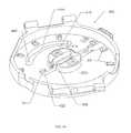
- FIG. 1shows a perspective view of a sampling device according to one example embodiment of the invention.
- FIG. 2shows a plan view of the sampling device of FIG. 1 .
- FIG. 3shows an exploded view of the sampling device of FIG. 1 having an open housing.
- FIG. 4shows an exploded representation of a carrier with lancets and test elements of the sampling device of FIG. 3 .
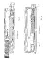
- FIG. 5is a view along a sectional plane through arrows A-A of FIG. 2 .
- FIG. 6is a view along a sectional plane through arrows B-B of FIG. 2 .
- FIG. 7is a plan view of a sampling device according to another example embodiment of the invention.
- FIGS. 8 and 9show a cassette of penetration elements and a detailed view of a lancet according to an example embodiment of the invention.
- FIGS. 10-13show a cassette of lancets according to another embodiment of the invention.
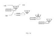
- FIG. 14shows an example drive mechanism for the lancets of FIGS. 10-13 , according to an example embodiment of the invention.
- FIGS. 15 and 16show a cassette of lancets according to yet another embodiment of the invention.
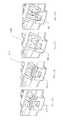
- FIGS. 17 a - dshow a sequence of operation of removal of a protective cap from a lancet, according to an example embodiment of the invention.
- FIG. 18shows an activation and release mechanism portion of a sampling device according to an example embodiment of the invention.
- FIGS. 19-21show an exploded representation and top and bottom views of a sampling device and lancets according to an embodiment of the present invention.
- FIGS. 22-28show a sequence of operation of an actuation cycle of the sampling device of FIGS. 19-21 .
- FIG. 29shows a partial internal view of a sampling device according to another embodiment of the invention.
- FIGS. 30-32show a sequence of operation of the device of FIG. 29 .
- FIG. 33shows a perspective view of another embodiment of the sampling device of the present invention.
- FIG. 34shows a partial interior view of the sampling device of FIG. 33 .
- FIGS. 35 and 36show exploded views of components of the sampling device of FIG. 33 .
- FIGS. 37 and 38are detailed views of an example embodiment of a lancet of the sampling device of the present invention.
- FIGS. 39 a - cshow a process for producing a lancet according to an example embodiment of the invention.
- FIG. 40is a perspective view of a lancet carrier according to an example embodiment of the present invention.
- FIG. 41is a perspective view of a retainer ring according to an example embodiment of the invention.
- FIGS. 42 and 43are perspective views of the carrier and lancets of a sampling device before and after use, respectively, according to an example embodiment of the present invention.
- FIGS. 44 and 45are partial perspective views of the housing of a sampling device, according to an example embodiment of the invention.
- FIG. 46is a perspective view of a piston or plunger element of the sampling device, according to an example embodiment of the present invention.
- FIG. 47is a perspective view of a release element of the sampling device, according to an example embodiment of the invention.
- FIG. 48is a perspective view of a tensioning or arming wheel element of the sampling device, according to an example embodiment of the present invention.
- FIG. 49is a bottom view of the sampling device, with the lower cover removed, according to an example embodiment of the invention.
- Rangesmay be expressed herein as from “about” or “approximately” one particular value and/or to “about” or “approximately” another particular value. When such a range is expressed, another embodiment includes from the one particular value and/or to the other particular value. Similarly, when values are expressed as approximations, by use of the antecedent “about,” it will be understood that the particular value forms another embodiment.
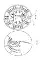
- FIGS. 1 and 2show a blood analysis device according to one example embodiment of the invention, which as a whole is designated by the reference number 2 .
- the blood analysis devicecomprises a housing 4 , which contains a blood withdrawal system 6 comprising at least one, and preferably a plurality of lancets 8 ; and at least one, and preferably a plurality of test elements 10 . Unused lancets 8 and test elements 10 are stored in the housing 4 , used, and, after use, removed again to be discarded or disposed of.
- the blood analysis device 2preferably further comprises an evaluation system 12 , preferably comprising an electronic evaluation system and a display 14 , preferably in the form of a visually readable display to show the result of an evaluation, such as for example the display of the quantity of an analyte such as blood sugar content.
- the depicted embodimentis an “all-in-one” device, comprising lancing features and sample collection and analysis features.
- the inventionis a lancing device, comprising only the lancing features, substantially as described, and omitting the sample collection and analysis features.
- the inventionis a sampling device, comprising only the sample collection and analysis features, and omitting the lancing features.
- the housing 4 of the blood analysis device 2preferably comprises a generally circular disk, having the general size, shape and appearance of the housing of a wristwatch. It preferably also comprises a pair of mutually opposing mounting elements 16 in the form of two openings 18 aligned with each other to hold a pin of an ordinary watchband, so that the device may be worn on the wrist of a user in the manner of a wristwatch.
- a puncture position 22 for application against a skin surface, such as a finger of a user,is provided at a wall 20 of the housing 4 .
- the puncture position 22preferably comprises a sliding ramp 24 defining a slotted opening 26 through which a lancet 8 is driven to pierce a skin surface of the user to obtain a sample of blood.
- the ramp 24is slidable along the wall 20 , to adjust the depth of penetration of the lancet 8 .
- the lancet 8is shown in FIG. 1 in its maximally extended position, which the lancet takes on for only an extremely brief time during performance of a puncture process. In the non-actuated state of the blood withdrawal device 6 the lancet 8 is fully within the housing 4 .
- a convex segment 28 of the housing 4can be moved partially out of the housing 4 so that the segment 28 opens exposes application position 30 which is oriented axially to the plane of the disk-shaped housing 4 .
- this application position 30a minimal amount of blood is applied to a test element 10 immediately below this application position.
- a test element 10is positioned beneath the application position 30 on the housing, wherein it can be wetted by a sample of blood, it is designated as being in its operating position.
- a lancet 8is in the puncture position 22 , in which it can penetrate into the skin surface of a user, it is designated as being in its operating position.
- the cover segment 28is preferably retained on a slide rail guide 38 so that it can be moved along a side 36 of the housing, which is curved convexly with respect to the inside by means of a rear grip on the remainder of the housing.
- the segment 28preferably covers the application position 30 in the non-actuated state of the blood withdrawal device so that its other convexly curved side 42 , preferably having a ribbed or other gripping surface 40 , forms a continuous part of the outer periphery of the housing 4 .
- the userslides cover segment 28 to the open position shown in FIG. 1 , so that the application position 30 is exposed.
- This movementsimultaneously cocks or activates the blood withdrawal device 6 inside the housing 4 , in that a piston or plunger mechanism is armed, as by mechanically tensioning or compressing a drive spring.
- the userthen places a finger or other sampling site against the puncture position 22 of the housing, and releases the blood withdrawal device, as by actuating a trigger button 46 .
- the piston or plunger 48 of the drive mechanism 44is driven radially outward, propelling the lancet outward into its operating position 34 , so that it penetrates into the skin surface of a user through the slotted opening 26 .
- the userremoves his or her finger from the puncture position 22 , allows a small sample of blood or other body fluid to exude from the wound, and then places the sample against the application position 30 , thus transferring a sample of body fluid to the test elements 10 in its operating position 32 . Then the evaluation of the analysis begins, and the result is displayed by the display means.
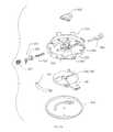
- FIGS. 4 to 6show an example embodiment of an arrangement of lancets 8 and test elements 10 according to the present invention, in connection with a blood withdrawal device 6 and plunger mechanism 44 within a housing 4 .
- FIG. 4shows a perspective view of a carrier or cassette 50 , according to an embodiment of the invention, and comprising a plurality of lancets 8 and a plurality of test elements 10 .
- the cassette 50is a magazine-like holder for lancets 8 and test elements 10 , which is manually manipulated for insertion into the device, for removal and replacement after use, and for disposal after use.
- the cassette 50preferably comprises a first carrier part 52 in the form of a generally flat circular disk 54 for retaining the test elements 10 , and a second carrier part 56 in the form of a strap or belt 58 formed into a circular ring with lancets 8 secured radially at spaced locations about its circumference.
- the second carrier part 56is preferably mounted on another ring-shaped third carrier part 60 , the plane of which extends generally parallel to that of the first carrier part 52 .
- the second carrier part 56 and the third carrier part 60are preferably coupled by engagement of recesses 62 in one part and projections 64 on the other part.
- the first carrier part 52is preferably coupled to the second carrier part 56 in a similar manner, so that recesses 62 and projections 66 interengage.
- the test elements 10are mounted concentrically within recesses 68 in the first carrier part 52 .
- the test elements 10are preferably oriented so as to be accessible in the axial direction (i.e., in the direction of an axis of rotation 70 of the carrier 50 ).
- Contacts 69are indicated for each test elements 10 on the top of the first carrier part 52 .
- An electrode systemnot shown, preferably contacts the test elements at the contacts 69 for communication with the evaluation system electronics, for example in the manner of known electrochemical test element operation.
- the radially arranged lancets 8 on the second carrier part 56each pass through a corresponding spring element 74 , which can be tensioned in the radial direction to arm and actuate the lancing device.
- the lancets 8have thickened heads 76 at the radial inside, which cannot pass through the spring element 74 .
- the spring element 74When the lancet 8 is driven outwardly in the radial direction, the spring element 74 is compressed, producing a spring force that withdraws the lancet 8 back into an equilibrium position inside the housing 4 , essentially as shown in FIG. 4 .
- the spring elements 74thus serve as retraction means 78 for the lancets 8 .
- the three carrier parts 52 , 56 and 60are preferably formed in the shape of rings, and have a central opening 80 in which the piston or plunger mechanism 44 is situated, as can be seen from FIG. 3 .
- the other carrier part 60preferably comprises internal gearing 82 , which interacts with a drive gear 84 .
- the drive gear 84is driven to advance the cassette 50 through sequential operating positions, as by an electric motor or manually as by actuation of a slide or by rotation of a manually operable wheel on the housing of the device.
- the cassette 50as shown in FIG. 3 , is preferably mounted rotationally on a projection 85 of the housing, which extends into the opening 80 . In this way, a plan axial surface 87 forms an axial bearing surface against which the other parts of the carrier part 60 lie so that they can slide, on the surface region immediately adjacent to the internal gear 82 .
- the plane of the sectionpasses through the operating position 32 of the test elements 10 .
- One lancet 8can also be seen in the sectional view. However, it is not in the operating position for lancets.
- the operating position for lancetsappears in the sectional plane of FIG. 6 , in which the lancet 8 is shown in its maximally extended position.
- the plunger mechanism 44 shown in FIG. 3is not shown in the sectional view of FIG. 6 . It can be seen from FIGS. 3 , 5 and 6 how the carrier 50 with the lancets 8 and test elements 10 can be inserted and removed as a replaceable cassette into the interior of the housing 4 of the blood analysis device.
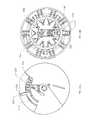
- FIG. 7shows a plan view of a blood analysis device 2 ′ which differs from that described above in that there is a time display means 92 in the form of an ordinary watch face on the visible side of the housing 4 .
- This time displaymay be in the form of mechanical hands, or a digital display, for example using one or more LCD display elements.
- a switchis preferably provided to allow the user to select between a time display and an operating mode that displays the result of the blood analysis.
- the depicted embodiment of the cassette 50combines lancing elements and sample collection and analysis elements on a single replaceable cassette. It will be recognized, however, that the present invention also includes cassettes comprising the lancing elements only, and omitting the sample collection and analysis elements; as well as cassettes comprising the sample collection and analysis elements only, and omitting the lancing elements.
- Separate lancing cassettes and sample collection and analysis cassettescan be used in tandem in an all-in-one lancing and sample analysis device, or alternatively can be used independently in lancing devices or in sample collection and analysis devices.
- FIGS. 8 and 9show a lancing cassette according to another embodiment of the present invention.
- a plurality of lancet elementsare mounted on a band or belt 102 .
- the lancetsare radially arranged in spaced locations about the circumference of a continuous ring-shaped belt 102 , in the form of a closed circle.
- a plurality of lancet elementsare mounted along the length of a strip-like belt.
- Each lancet elementcomprises a piston 106 translationally mounted within a cylinder or sleeve 100 .
- the piston 106carries the sharp lancet tip 114 at one end.
- At least one resilient tongue 108(two are shown) is mounted to the other end of the piston.
- the lancing cartridgepreferably further comprises a cover 112 , for example in the form of a section of thin film, sealing the open ends of the sleeves 100 to maintain sterility of the lancet tip 114 prior to use, and to prevent inadvertent sticks.
- the cover 112can either be penetrated by the lancet during lancing, or the cover can be removed partially or completely immediately before the lancing process is carried out.
- FIG. 9shows an enlarged cross-sectional view of a lancet element according to the embodiment of FIG. 8 .
- a sealin the form of an annular protuberance 118 from the wall 116 and an abutting protuberance 120 from the piston 106 .
- the two annular protuberances 118 , 120form a seal for the cylindrical space within the sleeve, so that the lancet tip 114 is held under sterile and sealed conditions.
- the cylindrical spaceis sealed off by the film 112 .
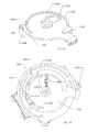
- FIGS. 10-13show another embodiment of a lancing cassette according to the present invention, in which a plurality of lancets 122 are held in hemispherical depressions 124 in a disk-shaped carrier part 126 , and are driven in the axial direction (i.e., parallel to the axis of rotation 70 of the carrier 126 ) upon actuation of the lancing device, as depicted in FIG. 14 .
- the carrier 126preferably comprises a ring of teeth 130 along one face 128 , serving as an end gear for rotating the carrier 126 within a lancing device.
- a depression defining internal gearingis formed in the face 128 of the carrier.
- each lancet 122is mounted, as by injection-molding, potting, or the like, into a carriage lug 132 , which is preferably integrally formed with the material of the hemispherical wall 133 forming the dome-shaped depression 124 .
- the depressions 124are preferably covered over by a film 134 , which hermetically seals the enclosed space to surrounding the lancet tip 122 to preserve sterility and prevent inadvertent needle-sticks.
- the walls of the hemispherical depressionsare preferably formed of a deformable and resilient material, and optionally further comprise annular weakening slots 136 for increased wall flexibility.
- FIG. 14shows an example drive mechanism for a lancing device for use with this embodiment of lancing cartridge.
- a transversely-driven plunger 138is arranged radially relative to the lancing cartridge.
- the plunger 138comprises a wedge-shaped ramp 140 for impacting the carriage lug 132 and deflecting the dome-shaped depression to drive the lancet tip 122 in the axial direction. After lancing, the ramp 140 retracts, and the resilient wall of the carrier 126 returns to its dome shape, withdrawing the lancet tip away from the sample site.
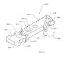
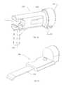
- FIGS. 15 and 16show perspective and exploded views, respectively, of another embodiment of a lancing cartridge for use in connection with a lancing device and/or a combined lancing and sample analysis device, according to the present invention.
- a plurality of lancet elementsare arranged on a rotatable carrier disk 142 .
- the lancet elementseach comprise a lancet tip 140 and a lancet body 144 , and are preferably arranged generally radially on the carrier disk, and are preferably formed of injection-molded plastic.
- One or more resilient tongues 146extend from the lancet body 144 , to retract the lancet tip 140 away from the sampling site after lancing and prevent forward movement of lancet after firing.
- the carrier disk 142preferably comprises guide projections projecting from its face to hold and act as a guide bearing for radial sliding movement of the lancet body 144 as it traverses a path between a retracted position and an extended position during the lancing operation.
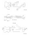
- the lancets tips 140are preferably injection-molded into the lancet body 144 , and are preferably encapsulated by a protective cap 147 , which provides a sterility and safety barrier for the lancet tip 140 .
- a spring member 148is affixed to the carrier disk 142 , serving as a guide allowing the lancet body 144 to translate back and forth in the radial direction, but preventing its loss or removal from the cassette.
- An extension arm 150 of the spring member 148extends over each protective cap 147 , and exerts downward pressure in the axial direction on the protective cap 147 toward the carrier disk 142 .
- the lancet body 144is retracted radially inward prior to actuating the lancing operation, for example in a cocking step, as shown in FIG. 17 b .
- the protective cap 147is constrained by the guide projections of the carrier disk 142 to ensure smooth travel of the lancet cap out of the firing position, and to prevent radial retraction of the cap, thereby separating the cap 147 from the lancet body 144 and exposing the lancet tip 140 .
- the extension arm 150 of the spring member 148then presses the separated protective cap 147 into a depression 152 formed in the carrier disk 142 , and out of the path of movement of the lancet.
- the lancet tip 140is driven outwardly, through a passage in the extension arm 150 , to pierce the skin at the sampling site, and is thereafter retracted away from the sampling site by the resilient tongues 146 and the retraction spring in the drive mechanism.
- FIG. 18shows schematically the means of activating a lancing device, according to an example embodiment of the invention.
- a drive mechanism 44comprises a piston or plunger 154 that is preferably generally coaxial with the centerline of the lancet which can be driven longitudinally, in the radial direction relative to a disk-shaped lancing cartridge, and withdrawn again by means of a tension and compression spring 156 .
- the plunger mechanismcan be armed by actuating a pivotal cocking means 158 comprising a radially projecting cam 160 .
- the cam 160engages with a cooperating projection 161 on the piston 154 so that the piston is moved against the compression force of the drive spring 156 such that it is held in an armed state by a catch mechanism or trigger 162 , holding the drive spring in tension.
- the positioning means 158 with the cam 160can then return back to its starting position as for example under spring force.
- the trigger catchis then manually released, causing the piston 154 to be driven longitudinally in the radial direction under the force of the spring, so that the free end of the piston 154 strikes the inner end of the lancet or of a holder which carries the lancet, and that likewise projects outward.
- the end of the piston 154comprises a clip or other engagement feature for engaging the lancet, and the lancet is carried along the traverse of the piston as it is cocked and released. Then the piston returns to its starting position as shown in FIG. 18 under the influence of the spring 156 , and/or the lancet is withdrawn into the housing under the action of the resilient tongue(s) as described above.
- FIGS. 19 to 29depict an example embodiment of a lancing device according to the present invention.
- FIG. 19shows an exploded view of a lancet cassette, which is shown in its assembled state from the top in FIG. 20 and from the bottom in FIG. 21 .
- the lancet cassettecomprises a carrier disk with a plurality of lancet elements 172 arranged radially thereon, each lancet having a sharp tip covered by a protective cap 174 , in similar fashion to the embodiment of FIG. 15 .
- the cassettefurther comprises a ring-shaped spring means 176 which interacts with each protective cap 174 , substantially as described above in connection with FIGS. 17 a - 17 d .
- These componentsare inserted into a housing mechanism base having a cylindrical wall region 180 extending upward.
- This mechanism basehas in its center an opening 182 projecting into the interior, forming a housing for a plunger or piston 184 , which is radially movable within it. Between a radial inner end 186 of the plunger 184 and a wall of the opening 182 which forms the housing, there is a first drive spring 188 . A return spring 192 is provided between a ring collar 190 of the plunger 184 and the opening 182 .
- the plunger 184also has a holder 194 at its circumference, preferably in the form of a circular slot by means of which the plunger 184 is held in the opening 182 with the spring 188 tensioned.
- a catch mechanismsuch as a clamping spring 196 preferably interacts with the holder.
- the plunger 184has a rear grasping element 198 at its radially outer end, which serves to draw back the lancet element 172 so as to remove the protective cap 174 .
- This rear grasping elementreleasably engages a cooperating section 200 of the lancet element 172 .
- This rear-holdable sectioncan for example, comprise an expanded surface feature 201 of the lancet element 172 which receives and releasably engages a cooperating surface feature of the plunger 184 .
- a control lever 202is pivotally mounted about the axis of rotation 70 of the carrier part 170 .
- the control lever 202preferably has a cam control surface 204 , which interacts with a cam means 206 of the plunger 184 , which extends in the axial direction through a cutout 208 in the base of the carrier part 178 .
- the cam control surface 204comes into active contact with the cam 206 and, on further rotation of the control lever 202 , forces the cam 206 with the plunger 184 radially inward so that the drive spring 188 is energized.
- a holding or catch mechanismsubstantially as described above, retains the plunger 184 with the spring 188 in an energized state, even when the control lever is returned to the initial position shown in FIG. 21 .
- the control lever 202also has a carrier 210 in the form of a notched lever 212 , by means of which the carrier part 170 and, with it, the arrangement of lancets, is rotationally advanced for successive lancing operations.
- the notched lever 212projects through a curved slotted opening 214 , extending along the peripheral direction in the base of the carrier part 178 and engages a cooperating portion of the carrier part 170 .
- the carrier partit is advantageous, for this purpose, for the carrier part to have a ratcheting, toothed end catch arrangement 216 as seen in FIG. 21 .
- the notched lever 212causes further rotation of the carrier part 170 so that a new lancet which has not yet been used is moved into its operating position.
- the rear-graspable section 200 of the particular lancet element 172slides into engagement with the rear grasping means 198 of the plunger 184 .
- the rear grasping means 198it is advantageous, to simplify this positioning end engagement, for the rear grasping means 198 to comprise an approach ramp or introductory ramp 218 which can be seen in FIG. 20 or FIG. 19 .
- this approach ramp 218which is preferably formed on confronting radially internal and radially external surfaces, it is possible to compensate for inaccuracies in positioning the plunger 184 .
- an interruption mechanism 220is positioned at the desired rotational position.
- This interruption mechanism 220preferably produces axial outward deflection of the notch lever 212 , so that its carrier 210 can no longer interact with the toothed end catch arrangement 216 .
- the notch lever 212has a radial projection 222 , which slides across an outer side of the carrier part 178 .
- This outer side of the carrier part 178has an approach ramp 224 at the appropriate place, which then raises the notch lever in the axial direction, in the sense described above, when the control lever 202 reaches this approach ramp 224 as it rotates.
- a means of preventing reverse rotation 226is preferably provided. It can advantageously be produced by an appropriately oriented end catch gear 228 on the inside of the carrier part 178 , as can be seen in FIG. 19 , for example.
- This end catch arrangement 228is made and oriented so that it interacts with the end catch arrangement of the first carrier part so that the carrier part 170 can be rotated in the direction of transport but not in the opposite direction.
- the carrier part 170is slightly deflectable by means of a cantilever arm 171 with respect to the other carrier part 178 to facilitate this action.
- FIGS. 22 to 28show an actuation cycle of the lancet arrangement, as described above.
- the left (a) view of each figureis a bottom view of the lancet cassette, and the right (b) view of each figure is a top view.
- FIG. 22shows the control lever 202 in its starting position, against a terminal stop 230 .
- a lancet element 172 with protective cap 174is shown, emphasized, in a position in front of the operating position of the lancet.
- FIG. 23depicts rotational movement of the control lever 202 in the clockwise direction.
- FIG. 23also shows the approach or introductory ramps 218 , discussed above, at the rear grasping means 198 of the plunger means.
- the radial projection 222 of the carrier armis deflected by the approach ramp 224 in the axial direction, and the tooth 212 of the carrier arm 210 is disengaged from the carrier part 170 so that the carrier part 170 is not turned farther.
- the cam guide surface 204 of the control lever 202presses the cam 206 inward in the radial direction, and the plunger means 184 with it, so that the plunger spring 188 is tensioned and the firing mechanism is armed.
- the rear grasping means 198 and the rear-graspable section 200 of the lancet element 172the lancet is carried radially inward, so that the lancet tip 232 , seen for the first time at the right of FIG.
- FIG. 25shows the maximally rotated position of the control lever 202 or the plunger 184 , in which the plunger 184 is held in this stressed position by a holding mechanism, which in this case is made up of the clamp spring 196 and the circular slot on plunger means 184 .
- a holding mechanismwhich in this case is made up of the clamp spring 196 and the circular slot on plunger means 184 .
- FIGS. 29-32show details of a drive means or plunger mechanism for a lancing device, according to another embodiment of the present invention. These figures also explain the activation (tensioning) of the drive means for the lancets and the further rotation of the carrier by means of a single control element 238 which is formed, as an example, from the cover part already discussed. (This is independent of the arrangement and formation of the lancets on a rotatable carrier.)
- FIG. 29shows a perspective view of the carrier components of this embodiment of the analytical device, with the components that make up the housing omitted. However, one can see the cover part 28 which has, at its inner side 36 , not only the sliding guide rail 38 discussed in connection with FIG.
- the shaft 244is forced into the position shown in FIG. 29 at one end of the slot 248 , in which the second gear wheel 246 meshes with the internal gear 82 of the carrier part 60 so that when the gear and shaft arrangement of carrier part 60 is rotated, and the arrangement of lancets is rotated clockwise.
- the cover part 28is slid or turned back to its initial position, then the gear wheel and shaft arrangement is forced to the opposite end of the slot 248 , so that the teeth of the second gear wheel 246 come out of contact with the internal gear 82 of carrier part 60 , thereby preventing reverse rotation of the arrangement of lancets 8 .
- the drive mechanism for a lancet in its operating positionis designated by the reference number 250 . It comprises a plunger mechanism 44 with a plunger 48 acting on a particular lancet. But the drive mechanism 250 also comprises a tensioning mechanism which, in this case, is made up of the second gear wheel 246 and a leaf spring 252 , and a release mechanism 254 comprising a lever arrangement 256 .
- One end of the leaf spring 252is fastened to a leaf spring holder 258 at the second gear wheel 246 and the other end is fastened to a leaf spring holder 260 at a part 262 which can pivot with respect to the housing 4 .
- This pivotable part 262is part of the lever arrangement 256 that connects this part 262 with a button 264 at the puncture position 22 on the housing 4 .
- the second gear wheel 246In a later outward movement of the cover part 28 the second gear wheel 246 not only turns the carrier part 60 farther, but it also pivots the leaf spring holder 258 , thus moving the leaf spring 252 to a tensioned state.
- the button 264By actuation of the button 264 , the other leaf spring holder 260 is likewise pivoted by the lever arrangement 256 so that the leaf spring 252 is suddenly released from its stable tensioned state past a dead point and the plunger 48 suddenly projects radially outward. That, in turn, likewise moves the lancet involved rapidly radially outward to carry out the puncture process. This course of the movement is shown in FIGS. 30 , 31 , and 32 .
- FIG. 30shows the drive means 250 of the blood withdrawal device in the non-activated initial state.
- the leaf spring 252has a bowed shape between the leaf spring holders 258 and 260 .
- the leaf spring holder 258 at the second gear wheel 246moves counterclockwise, and the leaf spring 252 takes on a form bent in an S shape. While this is going on, the leaf spring holder 260 and the position of the pivotable part 262 remain unchanged.
- the drive means 250 and its leaf spring 252are now in the tensioned activated state.
- the lever arrangement 256rotates the pivotable part 262 into the position shown in FIG. 32 a .
- the leaf spring 252is moved past a dead point and the spring energy stored in the spring, tensioned in the S shape, is suddenly released.
- the springreturns again to its bowed shape as shown in FIG. 32 a , but with curvature opposite that shown in FIG. 29 a . Due to the coupling of the leaf spring 252 with the plunger 48 of the plunger mechanism 244 , it is likewise projected suddenly outward.
- FIGS. 33 and 34show perspective views of a lancing device 302 for drawing a sample of blood from human or animal bodies for analysis, according to another embodiment of the invention.
- a cover part 304which is preferably connected so that it can pivot, shown in FIG. 33 , is omitted in FIG. 34 .
- Inside a housing 306a multiplicity of concentrically and radially arranged lancets 308 can be seen.
- a plunger system 310which defines a plunging or puncturing direction 312 , is visible in the center of the concentric arrangements.
- FIGS. 35 and 36show exploded views of the components housed within the housing 306 .
- the lancets 308which will be described in more detail below, can be seen. They have a protective cover or cap.
- FIG. 35shows their radial arrangement. They can slide in radial directions on a carrier 314 , preferably in the form of a circular disk, in guide paths or guide slots 316 of the carrier 314 .
- FIG. 35shows a circular disk 318 of spring steel above the lancet 308 . It holds the lancets 308 in a manner that will be described in more detail below in the guide slots 316 of the carrier 308 so that they cannot be lost but can be slid radially.
- test elements 324are loaded with the required sample of blood through a feed opening in the cover part 304 of the lancing device.
- an analysis test stripis passed out through a slot-like opening 328 and wetted with the sample of blood. Then an analysis is done amperometrically or potentiometrically, in known fashion, through the contacts 322 and an analysis system.
- the second carrier 320carries a number of test elements 324 corresponding to that of the lancets 308 .
- a displayfor example a digital or analog display for showing the time and/or sample analysis results.
- the device 302is optionally fastened about the wrist of a user using a band in the manner of a typical wristwatch.
- FIG. 36shows the housing 306 , which has a baseplate 332 with a cylindrical marginal section 334 projecting upward like a collar and a disk or dome-shaped elevation 336 in the center with sections with circular periphery 338 .
- a disk-shaped part 342At the lower side of the baseplate 332 there is a disk-shaped part 342 , with an actuating lever 340 which protrudes radially outwardly therefrom, and which can be rotated manually by a user. It is held at the bottom side of the baseplate 332 of the housing 306 by a cover part 344 on the baseplate side, so that it can be rotated.
- a retraction means in the form of a return spring 346is also shown.
- the disk-shaped part 342makes up a tensioning means 348 for the plunger system 310 .
- a plunger system 310is mounted in the center of the dome-shaped elevation 336 . It comprises a plunger piston 350 , which will be described in more detail below, a plunger spring 352 , and a recovery spring 354 , a release 356 and a cover 358 .
- the plunger system 310is activated by rotating the actuating lever 40 and thus rotating the disk-shaped part 342 , tensioning the plunger organ 350 against the pressure of the plunger spring 352 .
- the release means 356the plunger organ 350 moves rapidly in the radial direction and carries out a puncture process together with a lancet 308 .
- the lancet 308moves through a path of travel, from a retracted position to an extended (or lancing) position, shown in FIGS. 33 and 34 , wherein a finger or other sampling site of the subject has been positioned.
- the lancet tippenetrates the skin surface so that the user, immediately thereafter, can express a sample of blood from the wound.
- FIG. 37shows an enlarged perspective view of a lancet 308 with a protective covering.
- This coveringinvolves a lancet body 362 of plastic or similar material, which is preferably injection-molded to cover the metal needle lancet 308 (which comprises the sharpened lancet tip 365 ), and a protective cap 364 in the region of the tip 365 .
- the lancet 308is preferably held into the injection mold through an opening 366 left open in the body 362 .
- the lancet needle shaftmay be flattened or otherwise deformed along its length to ensure capture and retention by the injection molding process.
- the body 362 and the protective cap 364are preferably injection-molded in a single process.
- the body 362 and the protective cap 364meet at a thin-walled transition region 368 , which forms an area of weakening 370 .
- This weakened areacan be further weakened by cutting or otherwise forming a slit almost through the plastic.
- the body 362 and the protective cap 364are formed as separate components.
- An opening 372is preferably formed in the transition region 368 , which promotes development of the thin-walled area of weakening 370 . This opening 372 can, for instance, be produced in the injection-molding process by another holder for the lancet 308 .
- a resilient tongue or pin 374projects from the holder 362 at an oblique angle, for example of about 40° to the longitudinal direction of the lancet 308 , and preferably is integrally formed with the body 362 , and has a rounded free end 376 .
- the tongue 374can be spread apart or is elastically and resiliently deformable in the direction of the double arrow 378 with respect to the body 362 for the lancet 308 .
- the tongue 374assures stabilization in the plane of application for the body 362 and, for example, prevents tilting about the longitudinal direction.
- the tonguecan also serve to minimize oscillation of the lancet.
- the protective cap 364preferably has an H-shape in the plan view, having guide slots on both sides, with which it is held immovably in the longitudinal direction of lancet 308 (i.e., in the radial direction, on carrier 314 ), but it can slide transversely, perpendicular to the longitudinal direction of lancet 308 , with respect to the carrier.
- FIGS. 39 a - cshow example processes of production for separating the lancets 308 covered by the body 362 and protective capping means 364 during production.
- the end of the body 362 distal from the protective cap 364preferably comprises at least one shoulder or flange 418 projecting transversely outward from a side of the body, and has a step or recess 382 .
- a pair of opposed flangesproject from opposite sides of the body 362 for engagement with the drive mechanism, to withdraw the lancet along its longitudinal axis without misalignment during cocking.
- the lancet needle 308is cut off from a length of wire or tube by upper and lower knives 384 , 386 shown.
- the upper knife 384is placed nearly in contact with the step 382 so that its position can be defined with respect to the holder 362 and the lancet 308 , and the lancet needle 308 is cut off substantially flush with the lancet body 362 .
- FIGS. 40-43show the arrangement of the lancets 308 together with the bodies 362 and protective caps 364 on the carrier 314 .
- the carrier 314is preferably a generally circular disk having a raised pattern molded on its upper face.
- the carriercomprises ten radial guide channels, each channel bounded by a supporting wall 388 in the plane of the disk and two lateral guide walls 390 which are perpendicular to the disk and radially oriented.
- a lancet 308with holder 332 and protective cap 364 , is translationally slidable within each radial guide channel. The individual lancets 308 are inserted into the guide depressions from above, i.e., in the axial direction.
- FIGS. 34 and 42show the positions shown in FIGS. 34 and 42 . It can be seen that there is no lancet 308 in one arc segment 391 of the carrier.
- the carrier 314is positioned so that the arc segment 391 is oriented above the plunger system 310 , such that the radial outer end of the plunger system 310 extends into this circle segment 391 .
- the plunger means 350is arranged within the circle segment 391 as if between two adjacent lancets, the first and last lancets.
- a positioning aid in the form of an arrow-shaped profile of the circular disk 318is preferably provided to assist in the installation.
- a retainer 318preferably formed of a generally circular ring of spring steel, holds the lancets 308 in their positions within the guide depressions 316 of the carrier 314 .
- the circular disk 318is inserted, with a number of openings 392 on corresponding pins 394 of the carrier 314 .
- the pinsare expanded or attached to the disk 318 , as for example by ultrasonic welding.
- the circular disk 318 of spring steelhas radially projecting tongues 396 which are oriented parallel to the supporting wall 388 and which hold and guide a particular housing body 362 of a particular lancet 308 .
- Another tongue 398formed as a U-shaped loop, extends around each tongue 396 and the two legs of the U shape connect to the circular disk 318 .
- the loop-shaped tonguemakes up a displacement means 399 for the protective cap 364 to move it out of the path of movement of the lancet 308 .
- the connecting pins 400 of the tongue 398 running in the peripheral directionare slightly angled upward from the plane of the circular disk 318 and are somewhat flexible. Thus each one defines an attachment plane that is slightly oblique to the plane of the circular disk 318 .
- the connecting pins 400 and the planes formed by each of themare also oblique to the upper side 402 of the particular protective cap 364 .
- the particular connecting pin 400rests, under light pressure, on the upper side 402 of the protective cap 364 involved. If a holder 362 with the injection-molded lancet 308 is drawn radially inward and the region of weakening 370 between the holder 362 and the protective cap 364 is broken, then the loop-shaped tongue 398 with its connecting pin 400 forces the protective capping means 364 downward, transversely to the direction of puncture or the longitudinal direction of lancet 308 , into the position shown in FIG. 43 . In this disposal position 403 the surface of the connecting pin 400 of the spring tongue 398 lies against the top 402 of the particular protective capping means 364 . ( FIG.
- FIGS. 40 , 42 and 43show the lancet 308 after the puncture process has been carried out.
- Strip-shaped guide posts 404that enter the guide depressions 380 of the particular protective cap 364 .
- the particular protective cap 364can be slid on these guide posts 404 in the axial direction, i.e., perpendicular to the radially oriented puncture direction.
- these guide posts 404hold a particular protective cap 364 immovably in the radial direction, so that when the holder 362 is drawn inward the region of weakening 370 can be broken.
- each protective cap 364is held in a depression 406 in the carrier 314 , which forms the disposal position 403 for the protective cap. Then each protective cap is held immovably in this depression 406 by the loop-shaped spring tongue 398 to prevent any disturbing rattling noise.
- FIGS. 44-45show the housing 306 with and without the components involved with the drive system 310 . It can be seen that the dome-shaped elevation 336 in the housing 306 forms a holder for the plunger 350 , the plunger spring 352 and the withdrawal spring 354 . The cover 358 holds these components so that they cannot be lost and can be slid longitudinally into the holder, in the radial direction.
- FIG. 46shows, in a greatly enlarged presentation, the plunger 350 , which is designed as a piston or a ram. Its outside diameter is stepped down, so that it has an axial step 408 that supports one end of the withdrawal spring 354 . The other end of the withdrawal spring 354 is supported against one face 410 of the dome-shaped elevation 336 .
- the plunger spring 352is supported at the end with the greater diameter 412 , with the other end supported against a face 412 of the dome-shaped elevation 336 .
- the plunger means 358further comprises a coupling region 416 , which is open in the direction of plunger movement, as well as in the peripheral direction. This coupling region 416 is complementary to a rear gripping region 418 (see FIG. 37 ) of the lancet body 362 and can hold that region so that the body 362 can be coupled to the plunger 350 , forming a secure engagement with the plunger 350 .
- a coupling region 416which is open in the direction of plunger movement, as well as in the peripheral direction.
- This coupling region 416is complementary to a rear gripping region 418 (see FIG. 37 ) of the lancet body 362 and can hold that region so that the body 362 can be coupled to the plunger 350 , forming a secure engagement with the plunger 350 .
- a holder 362 for a lancet 308can be rotated into this coupling region 316 by rotating the carrier 314 , as can be seen in FIG. 34 . If the plunger 350 is drawn back radially inward, locked together with a lancet body 362 for a lancet 308 , so that the plunger spring 352 is tensioned, then the protective cap 364 , which is constrained against motion in the radial direction, cannot follow, and there is a break in the region of weakening 370 between them. As soon as the free sharp end 365 of the lancet 308 comes free of the protective cap 364 , the cap is moved into the disposal position 403 , as described previously, under the action of the loop-shaped spring tongue 398 .
- the lancet 308 along with the body 362follows the tensioning movement of the plunger 350 during this operation.
- the puncture system 310is in the activated or armed state, and can be actuated or triggered to carry out the puncture process by pressing the release 356 .
- the plunger 350has a tensioning cam 420 projecting transverse to the direction of puncturing.
- This tensioning cam 420extends through a linear hole 422 , which runs radially into the baseplate 332 of the housing 306 .
- the tensioning cam 420projects downward past the bottom side of the baseplate 332 . It enters an opening 424 in the disk-shaped part 342 , mentioned initially, with the radially projecting lever 340 .
- This openingforms a cam guide curve 426 such that the tensioning cam is displaced radially inward along this cam guide curve 426 by rotation of the disk-shaped part 342 .
- the plunger 350is moved radially inward against the force of the plunger spring 352 along the cam guide curve 426 and the tensioning cam 420 until a catch arm 430 of the release 356 catches in a catch cutout 432 in the larger-diameter section of the plunger means 350 , initially holding the plunger means 350 in the tensioned state.
- the actuating lever 340is released, it returns to its initial position under the action of the withdrawal spring 346 .
- the actuating lever 340 and the disk-shaped part 342make up a tensioning means 348 for the plunger system 310 .
- a resilient pin 434extends in the peripheral direction on the disk-shaped part 342 can be seen in FIG. 48 . Because of a slotted separation 436 , which extends generally in the peripheral direction, the pin 434 can be deflected slightly in the axial direction toward the plane of part 342 (see arrow 438 ). At the free end of the pin 434 there is a projection 440 extending in the axial direction. It enters the interior of the housing 306 through a slot-shaped cutout 442 extending peripherally in the base 332 of the housing 306 , as can be seen in FIG. 45 . When the actuating lever 340 of part 342 is pivoted, projection 440 moves along this slot-shaped cutout 442 .
- the projection 440is rotationally locked to the carrier 314 until the pin 434 with its projection 440 slides along the underside of the baseplate 332 of the housing 306 on a wedge-shaped ramp means 444 , as can be seen from FIGS. 44 and 45 .
- the pinis deflected downward and the projection 440 is withdrawn into the baseplate 332 , so that it is no longer rotationally locked to the carrier 314 . Therefore it is only during this phase that the tensioning cam 420 does not move inward.
- rotation of the carrier 314brings a lancet 308 that has not yet been used into the working position.
- the carrier 314is no longer located by the disengaged tooth 440 , and will now be more accurately positioned by the interaction between one of a series of spaced precision alignment grooves 331 in the interior base of the housing body with a cooperating tooth of the cantilevered ratchet lever 393 .
- the holder 362with its rear gripping means 418 arranged radially internally is rotated into the coupling region 416 of the plunger means 350 .
- the opening 424 in the disk-shaped part 342is designed and arranged so that the cam 420 of the plunger means 350 interacts at that moment with the cam guide path 426 , in which the next successive holder 362 has entered the coupling region 416 of the plunger means 350 and cannot be carried farther.
- the plunger means 350together with the holder 362 and the lancet 308 , are drawn radially inward by the tensioning cam 420 sliding along the cam guide curve 426 until the catch arm 430 catches, with a trapping hook, in the trap depression 432 of the plunger means 350 .
- the region of weakening 370 between the lancet body 362 and the protective cap 364is broken and the protective cap is moved into the disposal position shown in FIG. 43 , leaving the path of movement of the lancet 308 clear.
- the plunger 350moves rapidly in the radial direction along with the holder 312 and the lancet 308 , and the free end 365 of the lancet 308 moves, in an extremely short time, past the application position 360 to the outside of the housing 306 , so that it can penetrate the skin surface of a user in an extremely short time.
- the withdrawal spring 354is tensioned. Then it quickly pulls the holder 362 together with the lancet 308 back into the interior of the housing 306 .
- the spreadable pin 374then also supports the correct positioning of the used lancet 308 on the carrier 314 and, when a used carrier cassette is replaced by a new one, it prevents the used lancet with the holder 362 slipping in the radial direction out of the guide depressions 316 in the carrier 314 , assuring reliable disposal of used lancets.
- FIG. 49shows the underside of the baseplate 332 of the housing 306 , that is, without the base cover part 344 shown in FIG. 36 .
- the lancing device of this embodiment of the inventioncan be produced in the nature and size of a wrist-watch that can be worn at the user's wrist.
- the lancing devicehas a plurality (for example about 5 to 12) of lancets, which are inserted as a cassette onto the carrier 14 in the housing 6 .
- a useropens the cover part 304 and inserts a carrier cassette into the inside of the housing, noting the positioning of certain orientation marks, such as indicator 397 , which is initially aligned with the position of the piston of the drive mechanism.
- the cover part 304is then closed and a first lancet 308 is moved into the operating position by operation of the actuating lever 340 .
- the lancet 308or its body 362 , is engaged together with the plunger 350 and, in connection with that, is drawn radially inward.
- the protective cap 364is thereby removed, and is moved, transversely to the direction of puncture 312 , into a disposal position 403 on the carrier 314 .
- the plunger 350activated in this manner, is released, the plunger 350 , together with the body 362 and the lancet 308 , is accelerated in the radial direction by release of the plunger spring 352 , as by a blow. It is returned to the initial position again by the withdrawal spring 354 .
- FIG. 45shows the guide wall 601 is removed or shortened to allow easy movement of the lancet as it is removed from the piston
Landscapes
- Health & Medical Sciences (AREA)
- Life Sciences & Earth Sciences (AREA)
- Physics & Mathematics (AREA)
- Engineering & Computer Science (AREA)
- Animal Behavior & Ethology (AREA)
- General Health & Medical Sciences (AREA)
- Biophysics (AREA)
- Biomedical Technology (AREA)
- Heart & Thoracic Surgery (AREA)
- Medical Informatics (AREA)
- Molecular Biology (AREA)
- Surgery (AREA)
- Veterinary Medicine (AREA)
- Pathology (AREA)
- Public Health (AREA)
- Hematology (AREA)
- Geometry (AREA)
- Optics & Photonics (AREA)
- Manufacturing & Machinery (AREA)
- Dermatology (AREA)
- Measurement Of The Respiration, Hearing Ability, Form, And Blood Characteristics Of Living Organisms (AREA)
- Investigating Or Analysing Biological Materials (AREA)
- Sampling And Sample Adjustment (AREA)
- Automatic Analysis And Handling Materials Therefor (AREA)
Abstract
Description
Claims (11)
Priority Applications (1)
| Application Number | Priority Date | Filing Date | Title |
|---|---|---|---|
| US11/611,998US8870903B2 (en) | 2002-02-21 | 2006-12-18 | Blood sampling device |
Applications Claiming Priority (13)
| Application Number | Priority Date | Filing Date | Title |
|---|---|---|---|
| DE10208575ADE10208575C1 (en) | 2002-02-21 | 2002-02-21 | Blood analyzer device comprises needles, test media, analyzer and display, and has carrier turned with respect to main body, to position needle and test media |
| DE20213607.8 | 2002-02-21 | ||
| DE10208575.7 | 2002-02-21 | ||
| DE20213607UDE20213607U1 (en) | 2002-02-21 | 2002-02-21 | Blood analyzer for the determination of an analyte |
| DE10208575 | 2002-02-21 | ||
| US38763902P | 2002-06-11 | 2002-06-11 | |
| US41183402P | 2002-09-17 | 2002-09-17 | |
| DE10245721.2 | 2002-09-24 | ||
| DE10245721ADE10245721A1 (en) | 2002-02-21 | 2002-09-24 | Blood analyzer device comprises needles, test media, analyzer and display, and has carrier turned with respect to main body, to position needle and test media |
| US10/505,352US7883473B2 (en) | 2002-02-21 | 2003-02-20 | Blood sampling device |
| PCT/US2003/005159WO2003071940A1 (en) | 2002-02-21 | 2003-02-20 | Blood sampling device |
| US10/737,016US7150755B2 (en) | 2002-02-21 | 2003-12-12 | Blood sampling device |
| US11/611,998US8870903B2 (en) | 2002-02-21 | 2006-12-18 | Blood sampling device |
Related Parent Applications (5)
| Application Number | Title | Priority Date | Filing Date |
|---|---|---|---|
| US10/505,352ContinuationUS7883473B2 (en) | 2002-02-21 | 2003-02-20 | Blood sampling device |
| US10505352Continuation | 2003-02-20 | ||
| PCT/US2003/005159ContinuationWO2003071940A1 (en) | 2002-02-21 | 2003-02-20 | Blood sampling device |
| US10/737,016ContinuationUS7150755B2 (en) | 2002-02-21 | 2003-12-12 | Blood sampling device |
| US11/611,998ContinuationUS8870903B2 (en) | 2002-02-21 | 2006-12-18 | Blood sampling device |
Related Child Applications (1)
| Application Number | Title | Priority Date | Filing Date |
|---|---|---|---|
| US11/611,998ContinuationUS8870903B2 (en) | 2002-02-21 | 2006-12-18 | Blood sampling device |
Publications (2)
| Publication Number | Publication Date |
|---|---|
| US20070088377A1 US20070088377A1 (en) | 2007-04-19 |
| US8870903B2true US8870903B2 (en) | 2014-10-28 |
Family
ID=27588588
Family Applications (4)
| Application Number | Title | Priority Date | Filing Date |
|---|---|---|---|
| US10/505,352Active2026-09-17US7883473B2 (en) | 2002-02-21 | 2003-02-20 | Blood sampling device |
| US10/505,361AbandonedUS20060178600A1 (en) | 2002-02-21 | 2003-02-20 | Blood analyzer and pricking device for use in blood analysis |
| US10/737,016Expired - LifetimeUS7150755B2 (en) | 2002-02-21 | 2003-12-12 | Blood sampling device |
| US11/611,998Active2029-02-22US8870903B2 (en) | 2002-02-21 | 2006-12-18 | Blood sampling device |
Family Applications Before (3)
| Application Number | Title | Priority Date | Filing Date |
|---|---|---|---|
| US10/505,352Active2026-09-17US7883473B2 (en) | 2002-02-21 | 2003-02-20 | Blood sampling device |
| US10/505,361AbandonedUS20060178600A1 (en) | 2002-02-21 | 2003-02-20 | Blood analyzer and pricking device for use in blood analysis |
| US10/737,016Expired - LifetimeUS7150755B2 (en) | 2002-02-21 | 2003-12-12 | Blood sampling device |
Country Status (10)
| Country | Link |
|---|---|
| US (4) | US7883473B2 (en) |
| EP (2) | EP1485021B1 (en) |
| JP (1) | JP3977337B2 (en) |
| AT (1) | ATE298224T1 (en) |
| AU (2) | AU2003208880A1 (en) |
| CA (2) | CA2477104A1 (en) |
| DE (3) | DE20213607U1 (en) |
| ES (1) | ES2245771T3 (en) |
| PT (1) | PT1485021E (en) |
| WO (2) | WO2003071940A1 (en) |
Cited By (11)
| Publication number | Priority date | Publication date | Assignee | Title |
|---|---|---|---|---|
| US20130274579A1 (en)* | 2010-07-08 | 2013-10-17 | Sanofi-Aventis Deutschland Gmbh | Allowing measurements to be made of a blood sample |
| US9380970B2 (en) | 2011-02-05 | 2016-07-05 | Pops! Diabetes Care, Inc. | Lancet device with flexible cover |
| US20170102673A1 (en)* | 2015-10-11 | 2017-04-13 | Zahra Aboutalebi | Magic gluco-wrist watch (mgw) |
| US20180132774A1 (en)* | 2009-03-02 | 2018-05-17 | Seventh Sense Biosystems, Inc. | Delivering and/or receiving fluids |
| US10201294B2 (en) | 2012-01-10 | 2019-02-12 | Sanofi-Aventis Deutschland Gmbh | Apparatus comprising a lancet |
| US10390745B2 (en) | 2011-09-22 | 2019-08-27 | Sanofi-Aventis Deutschland Gmbh | Eliciting a blood sample |
| US10835163B2 (en) | 2011-04-29 | 2020-11-17 | Seventh Sense Biosystems, Inc. | Systems and methods for collecting fluid from a subject |
| US10939860B2 (en) | 2009-03-02 | 2021-03-09 | Seventh Sense Biosystems, Inc. | Techniques and devices associated with blood sampling |
| US11202895B2 (en) | 2010-07-26 | 2021-12-21 | Yourbio Health, Inc. | Rapid delivery and/or receiving of fluids |
| US11253179B2 (en) | 2011-04-29 | 2022-02-22 | Yourbio Health, Inc. | Systems and methods for collection and/or manipulation of blood spots or other bodily fluids |
| US12121353B2 (en) | 2010-11-09 | 2024-10-22 | Yourbio Health, Inc. | Systems and interfaces for blood sampling |
Families Citing this family (292)
| Publication number | Priority date | Publication date | Assignee | Title |
|---|---|---|---|---|
| US6036924A (en) | 1997-12-04 | 2000-03-14 | Hewlett-Packard Company | Cassette of lancet cartridges for sampling blood |
| US6391005B1 (en) | 1998-03-30 | 2002-05-21 | Agilent Technologies, Inc. | Apparatus and method for penetration with shaft having a sensor for sensing penetration depth |
| DE10057832C1 (en)* | 2000-11-21 | 2002-02-21 | Hartmann Paul Ag | Blood analysis device has syringe mounted in casing, annular mounting carrying needles mounted behind test strip and being swiveled so that needle can be pushed through strip and aperture in casing to take blood sample |
| US8641644B2 (en) | 2000-11-21 | 2014-02-04 | Sanofi-Aventis Deutschland Gmbh | Blood testing apparatus having a rotatable cartridge with multiple lancing elements and testing means |
| WO2002101359A2 (en) | 2001-06-12 | 2002-12-19 | Pelikan Technologies, Inc. | Integrated blood sampling analysis system with multi-use sampling module |
| US9226699B2 (en) | 2002-04-19 | 2016-01-05 | Sanofi-Aventis Deutschland Gmbh | Body fluid sampling module with a continuous compression tissue interface surface |
| US8337419B2 (en) | 2002-04-19 | 2012-12-25 | Sanofi-Aventis Deutschland Gmbh | Tissue penetration device |
| WO2005001418A2 (en)* | 2003-05-30 | 2005-01-06 | Pelikan Technologies, Inc. | Method and apparatus for body fluid sampling and analyte sensing |
| US20070100255A1 (en)* | 2002-04-19 | 2007-05-03 | Pelikan Technologies, Inc. | Method and apparatus for body fluid sampling and analyte sensing |
| AU2002344825A1 (en) | 2001-06-12 | 2002-12-23 | Pelikan Technologies, Inc. | Method and apparatus for improving success rate of blood yield from a fingerstick |
| EP1395185B1 (en) | 2001-06-12 | 2010-10-27 | Pelikan Technologies Inc. | Electric lancet actuator |
| US7981056B2 (en) | 2002-04-19 | 2011-07-19 | Pelikan Technologies, Inc. | Methods and apparatus for lancet actuation |
| JP4272051B2 (en) | 2001-06-12 | 2009-06-03 | ペリカン テクノロジーズ インコーポレイテッド | Blood sampling apparatus and method |
| JP4209767B2 (en) | 2001-06-12 | 2009-01-14 | ペリカン テクノロジーズ インコーポレイテッド | Self-optimized cutting instrument with adaptive means for temporary changes in skin properties |
| US7041068B2 (en) | 2001-06-12 | 2006-05-09 | Pelikan Technologies, Inc. | Sampling module device and method |
| US9427532B2 (en) | 2001-06-12 | 2016-08-30 | Sanofi-Aventis Deutschland Gmbh | Tissue penetration device |
| US7344507B2 (en) | 2002-04-19 | 2008-03-18 | Pelikan Technologies, Inc. | Method and apparatus for lancet actuation |
| US7749174B2 (en)* | 2001-06-12 | 2010-07-06 | Pelikan Technologies, Inc. | Method and apparatus for lancet launching device intergrated onto a blood-sampling cartridge |
| US9795747B2 (en) | 2010-06-02 | 2017-10-24 | Sanofi-Aventis Deutschland Gmbh | Methods and apparatus for lancet actuation |
| US7344894B2 (en) | 2001-10-16 | 2008-03-18 | Agilent Technologies, Inc. | Thermal regulation of fluidic samples within a diagnostic cartridge |
| US7004928B2 (en) | 2002-02-08 | 2006-02-28 | Rosedale Medical, Inc. | Autonomous, ambulatory analyte monitor or drug delivery device |
| DE20213607U1 (en) | 2002-02-21 | 2003-07-03 | Paul Hartmann AG, 89522 Heidenheim | Blood analyzer for the determination of an analyte |
| US7976476B2 (en) | 2002-04-19 | 2011-07-12 | Pelikan Technologies, Inc. | Device and method for variable speed lancet |
| US9795334B2 (en) | 2002-04-19 | 2017-10-24 | Sanofi-Aventis Deutschland Gmbh | Method and apparatus for penetrating tissue |
| US8221334B2 (en) | 2002-04-19 | 2012-07-17 | Sanofi-Aventis Deutschland Gmbh | Method and apparatus for penetrating tissue |
| US7717863B2 (en) | 2002-04-19 | 2010-05-18 | Pelikan Technologies, Inc. | Method and apparatus for penetrating tissue |
| US7491178B2 (en) | 2002-04-19 | 2009-02-17 | Pelikan Technologies, Inc. | Method and apparatus for penetrating tissue |
| US7901362B2 (en) | 2002-04-19 | 2011-03-08 | Pelikan Technologies, Inc. | Method and apparatus for penetrating tissue |
| US7232451B2 (en) | 2002-04-19 | 2007-06-19 | Pelikan Technologies, Inc. | Method and apparatus for penetrating tissue |
| US20070142748A1 (en)* | 2002-04-19 | 2007-06-21 | Ajay Deshmukh | Tissue penetration device |
| US7547287B2 (en) | 2002-04-19 | 2009-06-16 | Pelikan Technologies, Inc. | Method and apparatus for penetrating tissue |
| US7481776B2 (en) | 2002-04-19 | 2009-01-27 | Pelikan Technologies, Inc. | Method and apparatus for penetrating tissue |
| US8784335B2 (en) | 2002-04-19 | 2014-07-22 | Sanofi-Aventis Deutschland Gmbh | Body fluid sampling device with a capacitive sensor |
| US7374544B2 (en) | 2002-04-19 | 2008-05-20 | Pelikan Technologies, Inc. | Method and apparatus for penetrating tissue |
| US7229458B2 (en) | 2002-04-19 | 2007-06-12 | Pelikan Technologies, Inc. | Method and apparatus for penetrating tissue |
| US9248267B2 (en) | 2002-04-19 | 2016-02-02 | Sanofi-Aventis Deustchland Gmbh | Tissue penetration device |
| US8579831B2 (en) | 2002-04-19 | 2013-11-12 | Sanofi-Aventis Deutschland Gmbh | Method and apparatus for penetrating tissue |
| US9314194B2 (en) | 2002-04-19 | 2016-04-19 | Sanofi-Aventis Deutschland Gmbh | Tissue penetration device |
| US7674232B2 (en) | 2002-04-19 | 2010-03-09 | Pelikan Technologies, Inc. | Method and apparatus for penetrating tissue |
| US7892183B2 (en) | 2002-04-19 | 2011-02-22 | Pelikan Technologies, Inc. | Method and apparatus for body fluid sampling and analyte sensing |
| US7297122B2 (en) | 2002-04-19 | 2007-11-20 | Pelikan Technologies, Inc. | Method and apparatus for penetrating tissue |
| US8360992B2 (en) | 2002-04-19 | 2013-01-29 | Sanofi-Aventis Deutschland Gmbh | Method and apparatus for penetrating tissue |
| US7141058B2 (en) | 2002-04-19 | 2006-11-28 | Pelikan Technologies, Inc. | Method and apparatus for a body fluid sampling device using illumination |
| US7291117B2 (en) | 2002-04-19 | 2007-11-06 | Pelikan Technologies, Inc. | Method and apparatus for penetrating tissue |
| US7244265B2 (en) | 2002-04-19 | 2007-07-17 | Pelikan Technologies, Inc. | Method and apparatus for penetrating tissue |
| US7331931B2 (en) | 2002-04-19 | 2008-02-19 | Pelikan Technologies, Inc. | Method and apparatus for penetrating tissue |
| US7563232B2 (en) | 2002-04-19 | 2009-07-21 | Pelikan Technologies, Inc. | Method and apparatus for penetrating tissue |
| US7524293B2 (en) | 2002-04-19 | 2009-04-28 | Pelikan Technologies, Inc. | Method and apparatus for penetrating tissue |
| US8372016B2 (en)* | 2002-04-19 | 2013-02-12 | Sanofi-Aventis Deutschland Gmbh | Method and apparatus for body fluid sampling and analyte sensing |
| US8702624B2 (en) | 2006-09-29 | 2014-04-22 | Sanofi-Aventis Deutschland Gmbh | Analyte measurement device with a single shot actuator |
| US7909778B2 (en) | 2002-04-19 | 2011-03-22 | Pelikan Technologies, Inc. | Method and apparatus for penetrating tissue |
| US7410468B2 (en) | 2002-04-19 | 2008-08-12 | Pelikan Technologies, Inc. | Method and apparatus for penetrating tissue |
| US7485128B2 (en) | 2002-04-19 | 2009-02-03 | Pelikan Technologies, Inc. | Method and apparatus for penetrating tissue |
| US7708701B2 (en) | 2002-04-19 | 2010-05-04 | Pelikan Technologies, Inc. | Method and apparatus for a multi-use body fluid sampling device |
| US7371247B2 (en) | 2002-04-19 | 2008-05-13 | Pelikan Technologies, Inc | Method and apparatus for penetrating tissue |
| US7582099B2 (en) | 2002-04-19 | 2009-09-01 | Pelikan Technologies, Inc | Method and apparatus for penetrating tissue |
| US7648468B2 (en) | 2002-04-19 | 2010-01-19 | Pelikon Technologies, Inc. | Method and apparatus for penetrating tissue |
| US8267870B2 (en) | 2002-04-19 | 2012-09-18 | Sanofi-Aventis Deutschland Gmbh | Method and apparatus for body fluid sampling with hybrid actuation |
| WO2003088824A2 (en) | 2002-04-19 | 2003-10-30 | Pelikan Technologies, Inc. | Device and method for variable speed lancet |
| US7381184B2 (en) | 2002-11-05 | 2008-06-03 | Abbott Diabetes Care Inc. | Sensor inserter assembly |
| US8574895B2 (en) | 2002-12-30 | 2013-11-05 | Sanofi-Aventis Deutschland Gmbh | Method and apparatus using optical techniques to measure analyte levels |
| US20050155892A1 (en)* | 2003-03-04 | 2005-07-21 | Diaperoos, Llc | Graphic viewable through encasement of vacuum-packed diaper |
| DE10312357B3 (en)* | 2003-03-20 | 2004-07-08 | Roche Diagnostics Gmbh | Pricking aid for needle system for extraction of blood for medical diagnosis enclosing needle with opening for passage of needle point during puncturing of skin |
| US7052652B2 (en)* | 2003-03-24 | 2006-05-30 | Rosedale Medical, Inc. | Analyte concentration detection devices and methods |
| DE602004028463D1 (en) | 2003-05-30 | 2010-09-16 | Pelikan Technologies Inc | METHOD AND DEVICE FOR INJECTING LIQUID |
| US7850621B2 (en) | 2003-06-06 | 2010-12-14 | Pelikan Technologies, Inc. | Method and apparatus for body fluid sampling and analyte sensing |
| WO2006001797A1 (en) | 2004-06-14 | 2006-01-05 | Pelikan Technologies, Inc. | Low pain penetrating |
| EP1635700B1 (en) | 2003-06-13 | 2016-03-09 | Sanofi-Aventis Deutschland GmbH | Apparatus for a point of care device |
| WO2004112612A1 (en)* | 2003-06-20 | 2004-12-29 | Facet Technologies, Llc | Concealed lancet cartridge for lancing device |
| US20190357827A1 (en) | 2003-08-01 | 2019-11-28 | Dexcom, Inc. | Analyte sensor |
| US20080119703A1 (en) | 2006-10-04 | 2008-05-22 | Mark Brister | Analyte sensor |
| EP1653849B1 (en)* | 2003-08-11 | 2010-10-06 | Pelikan Technologies Inc. | Method and apparatus for body fluid sampling with integrated analyte detecting member |
| EP1663025A4 (en)* | 2003-08-20 | 2010-03-24 | Facet Technologies Llc | Blood sampling device |
| EP1659961A4 (en)* | 2003-08-20 | 2009-06-03 | Facet Technologies Llc | Blood sampling device |
| WO2005018454A2 (en)* | 2003-08-20 | 2005-03-03 | Facet Technologies, Llc | Multi-lancet device with sterility cap repositioning mechanism |
| WO2005018425A2 (en) | 2003-08-20 | 2005-03-03 | Facet Technologies, Llc | Blood sampling device |
| US8282576B2 (en) | 2003-09-29 | 2012-10-09 | Sanofi-Aventis Deutschland Gmbh | Method and apparatus for an improved sample capture device |
| EP1680014A4 (en) | 2003-10-14 | 2009-01-21 | Pelikan Technologies Inc | METHOD AND DEVICE FOR A VARIABLE USER INTERFACE |
| US8029454B2 (en) | 2003-11-05 | 2011-10-04 | Baxter International Inc. | High convection home hemodialysis/hemofiltration and sorbent system |
| USD902408S1 (en) | 2003-11-05 | 2020-11-17 | Abbott Diabetes Care Inc. | Analyte sensor control unit |
| US8038639B2 (en) | 2004-11-04 | 2011-10-18 | Baxter International Inc. | Medical fluid system with flexible sheeting disposable unit |
| EP1684634A2 (en)* | 2003-11-12 | 2006-08-02 | Facet Technologies, LLC | Lancing device and multi-lancet cartridge |
| US8221332B2 (en) | 2003-11-12 | 2012-07-17 | Facet Technologies, Llc | Multi-lancet cartridge and lancing device |
| EP1854409A3 (en) | 2003-11-12 | 2008-03-05 | Facet Technologies, LLC | Lancing device with depth-control mechanism |
| US7604118B2 (en)* | 2003-12-15 | 2009-10-20 | Panasonic Corporation | Puncture needle cartridge and lancet for blood collection |
| DE10361560A1 (en)* | 2003-12-23 | 2005-07-28 | Paul Hartmann Ag | Carrier with a plurality of lancing elements, lancing device and blood analyzer |
| US8668656B2 (en) | 2003-12-31 | 2014-03-11 | Sanofi-Aventis Deutschland Gmbh | Method and apparatus for improving fluidic flow and sample capture |
| US7822454B1 (en) | 2005-01-03 | 2010-10-26 | Pelikan Technologies, Inc. | Fluid sampling device with improved analyte detecting member configuration |
| WO2009048462A1 (en) | 2007-10-09 | 2009-04-16 | Dexcom, Inc. | Integrated insulin delivery system with continuous glucose sensor |
| US20050208593A1 (en)* | 2004-03-19 | 2005-09-22 | Arizona Board Of Regents, Acting For And On Behalf Of Northern Arizona University | Lateral flow diagnostic assay reader with radial cassette |
| JP2005270156A (en)* | 2004-03-23 | 2005-10-06 | Casio Comput Co Ltd | Arm mounted blood measuring device |
| US7377904B2 (en) | 2004-04-16 | 2008-05-27 | Facet Technologies, Llc | Cap displacement mechanism for lancing device and multi-lancet cartridge |
| US8591436B2 (en)* | 2004-04-30 | 2013-11-26 | Roche Diagnostics Operations, Inc. | Lancets for bodily fluid sampling supplied on a tape |
| CN100443049C (en)* | 2004-05-17 | 2008-12-17 | 泉株式会社 | Lancet Components |
| WO2006011062A2 (en) | 2004-05-20 | 2006-02-02 | Albatros Technologies Gmbh & Co. Kg | Printable hydrogel for biosensors |
| US9775553B2 (en) | 2004-06-03 | 2017-10-03 | Sanofi-Aventis Deutschland Gmbh | Method and apparatus for a fluid sampling device |
| WO2005120365A1 (en) | 2004-06-03 | 2005-12-22 | Pelikan Technologies, Inc. | Method and apparatus for a fluid sampling device |
| US7299081B2 (en)* | 2004-06-15 | 2007-11-20 | Abbott Laboratories | Analyte test device |
| US7837633B2 (en)* | 2004-06-30 | 2010-11-23 | Facet Technologies, Llc | Lancing device and multi-lancet cartridge |
| DE102004037270B4 (en) | 2004-07-31 | 2008-01-31 | Roche Diagnostics Gmbh | Blood collection system for taking blood for diagnostic purposes |
| DE102004042886A1 (en) | 2004-09-04 | 2006-03-30 | Roche Diagnostics Gmbh | Lancet device for creating a puncture wound |
| US7604604B2 (en) | 2004-09-09 | 2009-10-20 | Roche Diagnostics Operations, Inc. | Device for sampling bodily fluids |
| US7645241B2 (en)* | 2004-09-09 | 2010-01-12 | Roche Diagnostics Operations, Inc. | Device for sampling bodily fluids |
| US8211038B2 (en) | 2004-09-17 | 2012-07-03 | Abbott Diabetes Care Inc. | Multiple-biosensor article |
| US7458942B2 (en)* | 2004-09-22 | 2008-12-02 | Medtox | Systems and methods for collecting, testing and transporting liquid biological specimens |
| CN100490744C (en) | 2004-10-06 | 2009-05-27 | 泉株式会社 | Lancet Components |
| JP2006109894A (en)* | 2004-10-12 | 2006-04-27 | Casio Comput Co Ltd | Blood component measuring device |
| US20090105569A1 (en) | 2006-04-28 | 2009-04-23 | Abbott Diabetes Care, Inc. | Introducer Assembly and Methods of Use |
| US7697967B2 (en) | 2005-12-28 | 2010-04-13 | Abbott Diabetes Care Inc. | Method and apparatus for providing analyte sensor insertion |
| US10226207B2 (en) | 2004-12-29 | 2019-03-12 | Abbott Diabetes Care Inc. | Sensor inserter having introducer |
| US8333714B2 (en) | 2006-09-10 | 2012-12-18 | Abbott Diabetes Care Inc. | Method and system for providing an integrated analyte sensor insertion device and data processing unit |
| US8512243B2 (en) | 2005-09-30 | 2013-08-20 | Abbott Diabetes Care Inc. | Integrated introducer and transmitter assembly and methods of use |
| US9259175B2 (en) | 2006-10-23 | 2016-02-16 | Abbott Diabetes Care, Inc. | Flexible patch for fluid delivery and monitoring body analytes |
| US9788771B2 (en) | 2006-10-23 | 2017-10-17 | Abbott Diabetes Care Inc. | Variable speed sensor insertion devices and methods of use |
| US8029441B2 (en) | 2006-02-28 | 2011-10-04 | Abbott Diabetes Care Inc. | Analyte sensor transmitter unit configuration for a data monitoring and management system |
| US9572534B2 (en) | 2010-06-29 | 2017-02-21 | Abbott Diabetes Care Inc. | Devices, systems and methods for on-skin or on-body mounting of medical devices |
| US7883464B2 (en) | 2005-09-30 | 2011-02-08 | Abbott Diabetes Care Inc. | Integrated transmitter unit and sensor introducer mechanism and methods of use |
| US9398882B2 (en) | 2005-09-30 | 2016-07-26 | Abbott Diabetes Care Inc. | Method and apparatus for providing analyte sensor and data processing device |
| US8652831B2 (en) | 2004-12-30 | 2014-02-18 | Sanofi-Aventis Deutschland Gmbh | Method and apparatus for analyte measurement test time |
| US8934955B2 (en)* | 2005-01-18 | 2015-01-13 | Stat Medical Devices, Inc. | Cartridge with lancets and test strips and testing device using the cartridge |
| US9289161B2 (en) | 2005-01-28 | 2016-03-22 | Stat Medical Divices, Inc. | Multi-lancet unit, method and lancet device using the multi-lancet unit, and method of assembling and/or making the multi-lancet unit |
| US7695442B2 (en) | 2005-04-12 | 2010-04-13 | Roche Diagnostics Operations, Inc. | Integrated lancing test strip with retractable lancet |
| EP1702564A1 (en)* | 2005-03-18 | 2006-09-20 | Futumeds SDN. BHD | Lancet activating device |
| EP1877778A1 (en)* | 2005-03-22 | 2008-01-16 | Bayer HealthCare LLC | Packaging container for test sensors |
| US7913838B2 (en)* | 2005-03-22 | 2011-03-29 | Bayer Healthcare Llc | Packaging container for test sensors |
| USD581533S1 (en) | 2005-04-15 | 2008-11-25 | Facet Technologies, Llc | Multi-lancet lancing device |
| USD605290S1 (en) | 2005-04-15 | 2009-12-01 | Facet Technologies, Llc | Multi-lancet cartridge for a lancing device |
| ATE485001T1 (en)* | 2005-05-20 | 2010-11-15 | Hoffmann La Roche | LANCET SYSTEM WITH STERILE PROTECTION |
| US8211036B2 (en)* | 2005-05-27 | 2012-07-03 | Stat Medical Devices, Inc. | Disposable lancet device cap with integral lancet and/or test strip and testing device utilizing the cap |
| GB2426709A (en)* | 2005-05-31 | 2006-12-06 | Owen Mumford Ltd | Lancet |
| US20060281187A1 (en) | 2005-06-13 | 2006-12-14 | Rosedale Medical, Inc. | Analyte detection devices and methods with hematocrit/volume correction and feedback control |
| EP1743577A1 (en)* | 2005-06-23 | 2007-01-17 | Roche Diagnostics GmbH | Hand-held apparatus for the analysis of bodily fluids |
| US20100081968A1 (en)* | 2005-07-15 | 2010-04-01 | Home Diagnostics, Inc. | Test Strip With Integrated Lancet |
| US8636672B2 (en)* | 2007-02-28 | 2014-01-28 | Nipro Diagnostics, Inc. | Test strip with integrated lancet |
| FI121698B (en)* | 2005-07-19 | 2011-03-15 | Ihq Innovation Headquarters Oy | Health monitoring device and sensor cassette for the health monitoring device |
| AR057500A1 (en)* | 2005-08-12 | 2007-12-05 | Bayer Healthcare Llc | INTEGRATED ANALYSIS SYSTEM TO MONITOR BODY FLUIDS |
| JP4642082B2 (en) | 2005-09-29 | 2011-03-02 | 泉株式会社 | Lancet assembly and lancing device |
| EP1928302B1 (en) | 2005-09-30 | 2012-08-01 | Intuity Medical, Inc. | Fully integrated wearable or handheld monitor |
| US9521968B2 (en) | 2005-09-30 | 2016-12-20 | Abbott Diabetes Care Inc. | Analyte sensor retention mechanism and methods of use |
| US8801631B2 (en)* | 2005-09-30 | 2014-08-12 | Intuity Medical, Inc. | Devices and methods for facilitating fluid transport |
| US7704265B2 (en) | 2005-11-03 | 2010-04-27 | Stat Medical Devices, Inc. | Disposable/single-use blade lancet device and method |
| WO2007059048A1 (en)* | 2005-11-14 | 2007-05-24 | Bayer Healthcare Llc | Compact foldable meter |
| US8353848B2 (en)* | 2005-11-21 | 2013-01-15 | Alere Switzerland Gmbh | Test device |
| EP1795117A1 (en)* | 2005-12-12 | 2007-06-13 | F. Hoffmann-La Roche AG | Patient device with remote user interface |
| US11298058B2 (en) | 2005-12-28 | 2022-04-12 | Abbott Diabetes Care Inc. | Method and apparatus for providing analyte sensor insertion |
| GB2434542A (en)* | 2006-01-31 | 2007-08-01 | Owen Mumford Ltd | Single-use skin pricking device |
| USD557807S1 (en)* | 2006-06-09 | 2007-12-18 | Hawaii Medical, Inc. | Combined blade cover and alignment mechanism for a lancet |
| US20070299458A1 (en)* | 2006-06-10 | 2007-12-27 | Epple John A | Renewable rotary skin lancet |
| KR20090031763A (en)* | 2006-07-06 | 2009-03-27 | 라피딕스 리미티드. | Integrated blood sampling and testing device and method |
| DE502006007846D1 (en)* | 2006-07-18 | 2010-10-21 | Roche Diagnostics Gmbh | lancet |
| EP1881322B8 (en)* | 2006-07-18 | 2011-09-28 | Roche Diagnostics GmbH | Space-optimised portable measuring system |
| US7846110B2 (en)* | 2006-08-03 | 2010-12-07 | Advanced Medical Products Gmbh | Self-contained test unit for testing body fluids |
| US7927345B2 (en)* | 2006-11-02 | 2011-04-19 | Agamatrix, Inc. | Lancet cartridges and lancing devices |
| WO2008064333A2 (en)* | 2006-11-21 | 2008-05-29 | Stat Medical Devices, Inc. | Lancet device utilizing a revolver-type cartridge, revolver-type cartridge, and method of making and/or using the cartridge and the lancet device |
| WO2008085052A2 (en) | 2007-01-11 | 2008-07-17 | Arnoldus Huibert Klapwijk | Testing device |
| EP1967139A1 (en)* | 2007-03-09 | 2008-09-10 | Roche Diagnostics GmbH | Disposable puncturing device and resuable handling device for a puncturing device |
| WO2008111937A1 (en)* | 2007-03-12 | 2008-09-18 | Bayer Healthcare Llc | Analyte-testing instruments |
| EP1974667A1 (en)* | 2007-03-29 | 2008-10-01 | Roche Diagnostics GmbH | Piercing system |
| US8469986B2 (en) | 2007-03-30 | 2013-06-25 | Stat Medical Devices, Inc. | Lancet device with combined trigger and cocking mechanism and method |
| EP1982653A1 (en)* | 2007-04-18 | 2008-10-22 | Roche Diagnostics GmbH | Pricking device and analysis device |
| ES2354912T3 (en)* | 2007-05-16 | 2011-03-21 | Roche Diagnostics Gmbh | PUNCTURE SYSTEM |
| WO2008157610A1 (en) | 2007-06-19 | 2008-12-24 | Stat Medical Devices, Inc. | Lancet device with depth adjustment and lancet removal system and method |
| JP5546243B2 (en)* | 2007-07-18 | 2014-07-09 | パナソニックヘルスケア株式会社 | Blood test equipment |
| GB2451839A (en) | 2007-08-14 | 2009-02-18 | Owen Mumford Ltd | Lancing device |
| WO2009026394A1 (en)* | 2007-08-20 | 2009-02-26 | Pelikan Technologies, Inc. | Body fluid sampling systems |
| GB0716427D0 (en)* | 2007-08-23 | 2007-10-03 | Smartsensor Telemed Ltd | Glucose tolerance test device |
| US9186097B2 (en) | 2007-09-17 | 2015-11-17 | Roche Diabetes Care, Inc. | Body fluid lancing, acquiring, and testing cartridge design |
| US8961431B2 (en)* | 2009-09-28 | 2015-02-24 | Roche Diagnostics Operations, Inc. | Body fluid lancing, acquiring, and testing cartridge design |
| EP2039293A1 (en)* | 2007-09-19 | 2009-03-25 | F. Hoffman-la Roche AG | Combination drive for a sample extraction system for obtaining a liquid sample |
| EP2042098A1 (en)* | 2007-09-26 | 2009-04-01 | Roche Diagnostics GmbH | Lancet cartridge |
| EP2050392B1 (en) | 2007-10-15 | 2012-09-05 | Roche Diagnostics GmbH | Lancet wheel |
| US8114276B2 (en) | 2007-10-24 | 2012-02-14 | Baxter International Inc. | Personal hemodialysis system |
| WO2009081405A2 (en)* | 2007-12-25 | 2009-07-02 | Rapidx Ltd. | Devices and methods for reduced-pain blood sampling |
| US9392968B2 (en)* | 2008-01-23 | 2016-07-19 | Stat Medical Devices, Inc. | Lancet needle cartridge, cartridge lancet device, and method of using and making the same |
| AU2009219678A1 (en)* | 2008-02-27 | 2009-09-03 | Mon4D Ltd. | Device, system and method for modular analyte monitoring |
| EP2253269B1 (en)* | 2008-03-18 | 2013-05-22 | Panasonic Corporation | Blood collecting puncture device and magazine used for the same |
| EP2265324B1 (en) | 2008-04-11 | 2015-01-28 | Sanofi-Aventis Deutschland GmbH | Integrated analyte measurement system |
| EP2113197A1 (en)* | 2008-05-03 | 2009-11-04 | Roche Diagnostics GmbH | Lancet wheel and method for manufacturing a lancet wheel |
| US9833183B2 (en) | 2008-05-30 | 2017-12-05 | Intuity Medical, Inc. | Body fluid sampling device—sampling site interface |
| WO2009148624A1 (en) | 2008-06-06 | 2009-12-10 | Intuity Medical, Inc. | Detection meter and mode of operation |
| EP3984454A1 (en) | 2008-06-06 | 2022-04-20 | Intuity Medical, Inc. | Medical diagnostic devices and methods |
| US20100004522A1 (en)* | 2008-07-02 | 2010-01-07 | Eddie Varela | Continuously Wearable Compact Blood Glucose Measuring Device |
| USD621045S1 (en) | 2009-07-02 | 2010-08-03 | Facet Technologies, Llc | Lancet |
| EP2337497A2 (en) | 2008-07-29 | 2011-06-29 | Facet Technologies, LLC | Lancets with improved coupling features and sterility caps |
| US8057501B2 (en)* | 2008-08-25 | 2011-11-15 | Abbott Diabetes Care Inc. | Collapsible lancing device |
| EP2341829A4 (en) | 2008-10-03 | 2012-11-28 | Abbott Diabetes Care Inc | Integrated lancet and analyte testing apparatus |
| US20100187132A1 (en)* | 2008-12-29 | 2010-07-29 | Don Alden | Determination of the real electrochemical surface areas of screen printed electrodes |
| US9375169B2 (en) | 2009-01-30 | 2016-06-28 | Sanofi-Aventis Deutschland Gmbh | Cam drive for managing disposable penetrating member actions with a single motor and motor and control system |
| US20100198107A1 (en)* | 2009-01-30 | 2010-08-05 | Roche Diagnostics Operations, Inc. | Integrated blood glucose meter and lancing device |
| US9402544B2 (en) | 2009-02-03 | 2016-08-02 | Abbott Diabetes Care Inc. | Analyte sensor and apparatus for insertion of the sensor |
| ZA200901253B (en)* | 2009-02-13 | 2010-07-28 | Alexandro Ricardo Frau | Educational ruler |
| PL2218399T3 (en) | 2009-02-17 | 2014-03-31 | Hoffmann La Roche | Reuse protection for lancet system |
| EP2221001A1 (en)* | 2009-02-18 | 2010-08-25 | Roche Diagnostics GmbH | Handheld analysis tool |
| EP2226008A1 (en)* | 2009-02-19 | 2010-09-08 | Roche Diagnostics GmbH | Method for producing an analytical magazine |
| CN102325496B (en) | 2009-02-19 | 2015-10-07 | 霍夫曼-拉罗奇有限公司 | The joint space-efficient analyzing aid stores |
| EP2226007A1 (en) | 2009-02-19 | 2010-09-08 | Roche Diagnostics GmbH | Test element magazine with covered test fields |
| US20110125058A1 (en)* | 2009-11-24 | 2011-05-26 | Seven Sense Biosystems, Inc. | Patient-enacted sampling technique |
| USD621044S1 (en) | 2009-07-02 | 2010-08-03 | Facet Technologies, Llc | Lancet |
| WO2011005971A1 (en)* | 2009-07-09 | 2011-01-13 | Cook Incorporated | Spring action medical device |
| US9517027B2 (en) | 2009-07-10 | 2016-12-13 | Facet Techonologies, Llc | Advancement mechanism for cartridge-based devices |
| EP3001194B1 (en) | 2009-08-31 | 2019-04-17 | Abbott Diabetes Care, Inc. | Medical devices and methods |
| WO2011038386A2 (en)* | 2009-09-28 | 2011-03-31 | Facet Technologies, Llc | Advancement mechanism for cartridge-based devices |
| EP2311374A1 (en)* | 2009-10-13 | 2011-04-20 | Roche Diagnostics GmbH | Apparatus for retrieving and analysing blood; coupling mechanism for lancets |
| WO2011053787A2 (en)* | 2009-10-30 | 2011-05-05 | Seventh Sense Biosystems, Inc. | Systems and methods for application to skin and control of actuation, delivery and/or perception thereof |
| WO2011053796A2 (en)* | 2009-10-30 | 2011-05-05 | Seventh Sense Biosystems, Inc. | Systems and methods for treating, sanitizing, and/or shielding the skin or devices applied to the skin |
| EP2316338A1 (en)* | 2009-11-02 | 2011-05-04 | Roche Diagnostics GmbH | Lancet hook for use in a lancet device |
| PL2503938T3 (en) | 2009-11-24 | 2014-03-31 | Hoffmann La Roche | Belt magazine with backing block and integrated belt release |
| EP2506768B1 (en) | 2009-11-30 | 2016-07-06 | Intuity Medical, Inc. | Calibration material delivery devices and methods |
| CN102811754B (en)* | 2010-01-13 | 2017-05-17 | 第七感生物系统有限公司 | Rapid delivery and/or withdrawal of fluids |
| WO2011088211A2 (en)* | 2010-01-13 | 2011-07-21 | Seventh Sense Biosystems, Inc. | Sampling device interfaces |
| WO2011094573A1 (en) | 2010-01-28 | 2011-08-04 | Seventh Sense Biosystems, Inc. | Monitoring or feedback systems and methods |
| DE102010010438A1 (en) | 2010-02-26 | 2011-09-01 | Dr. Ing. H.C. F. Porsche Aktiengesellschaft | Suspension for a motor vehicle with an electrical axis |
| LT3622883T (en) | 2010-03-24 | 2021-08-25 | Abbott Diabetes Care, Inc. | Medical device inserters and processes of inserting and using medical devices |
| US8965476B2 (en) | 2010-04-16 | 2015-02-24 | Sanofi-Aventis Deutschland Gmbh | Tissue penetration device |
| EP2384694A1 (en) | 2010-05-05 | 2011-11-09 | Roche Diagnostics GmbH | Method for producing a membrane ring or test strip ring |
| WO2011163347A2 (en) | 2010-06-23 | 2011-12-29 | Seventh Sense Biosystems, Inc. | Sampling devices and methods involving relatively little pain |
| CA2803797A1 (en) | 2010-06-25 | 2011-12-29 | Intuity Medical, Inc. | Analyte monitoring methods and systems |
| US11064921B2 (en) | 2010-06-29 | 2021-07-20 | Abbott Diabetes Care Inc. | Devices, systems and methods for on-skin or on-body mounting of medical devices |
| TWI522087B (en)* | 2010-07-08 | 2016-02-21 | 賽諾菲阿凡提斯德意志有限公司 | Blood sample collection |
| TW201212887A (en)* | 2010-07-08 | 2012-04-01 | Sanofi Aventis Deutschland | Eliciting a blood sample |
| US20120016308A1 (en) | 2010-07-16 | 2012-01-19 | Seventh Sense Biosystems, Inc. | Low-pressure packaging for fluid devices |
| WO2012021801A2 (en) | 2010-08-13 | 2012-02-16 | Seventh Sense Biosystems, Inc. | Systems and techniques for monitoring subjects |
| JP5482564B2 (en)* | 2010-08-18 | 2014-05-07 | ソニー株式会社 | Bioactive substance collection device |
| EP2460471B1 (en) | 2010-12-04 | 2013-07-03 | Roche Diagnostics GmbH | Lancet device with optionally reusable stored lancets |
| US8158428B1 (en) | 2010-12-30 | 2012-04-17 | General Electric Company | Methods, systems and apparatus for detecting material defects in combustors of combustion turbine engines |
| US8852123B2 (en) | 2010-12-30 | 2014-10-07 | Roche Diagnostics Operations, Inc. | Handheld medical diagnostic devices housing with sample transfer |
| US9717452B2 (en) | 2010-12-30 | 2017-08-01 | Roche Diabetes Care, Inc. | Handheld medical diagnostic devices with lancing speed control |
| EP2697650B1 (en) | 2011-04-15 | 2020-09-30 | Dexcom, Inc. | Advanced analyte sensor calibration and error detection |
| US20130158468A1 (en) | 2011-12-19 | 2013-06-20 | Seventh Sense Biosystems, Inc. | Delivering and/or receiving material with respect to a subject surface |
| EP2522378A1 (en)* | 2011-05-11 | 2012-11-14 | Sanofi-Aventis Deutschland GmbH | Needle assembly storage device |
| US8333716B1 (en) | 2011-06-21 | 2012-12-18 | Yofimeter, Llc | Methods for using an analyte testing device |
| US20120330188A1 (en)* | 2011-06-21 | 2012-12-27 | Gadlight, Inc. | Cocking and Advancing Mechanism for Analyte Testing Device |
| US20130085349A1 (en) | 2011-06-21 | 2013-04-04 | Yofimeter, Llc | Analyte testing devices |
| US9782114B2 (en) | 2011-08-03 | 2017-10-10 | Intuity Medical, Inc. | Devices and methods for body fluid sampling and analysis |
| EP2713879B1 (en) | 2011-12-11 | 2017-07-26 | Abbott Diabetes Care, Inc. | Analyte sensor devices, connections, and methods |
| CA2857503C (en) | 2011-12-15 | 2020-10-27 | Facet Technologies, Llc | Latch mechanism for preventing lancet oscillation in a lancing device |
| US10258270B2 (en) | 2012-01-10 | 2019-04-16 | Sanofi-Aventis Deutschland Gmbh | Apparatus for eliciting a blood sample |
| USD676549S1 (en)* | 2012-03-13 | 2013-02-19 | Becton Dickinson France S.A.S. | Medical injector |
| US10085681B2 (en) | 2012-04-11 | 2018-10-02 | Facet Technologies, Llc | Lancing device with moving pivot depth adjust |
| WO2014018928A1 (en)* | 2012-07-27 | 2014-01-30 | Abbott Diabetes Care Inc. | Medical device applicators |
| JP6313769B2 (en)* | 2012-09-27 | 2018-04-18 | ファセット テクノロジーズ エルエルシーFacet Technologies, LLC | Depth adjustment mechanism for puncture device |
| US9801965B2 (en) | 2013-03-18 | 2017-10-31 | Sensor Electronic Technology, Inc. | Ultraviolet disinfection case |
| DE112014001503B4 (en)* | 2013-03-18 | 2022-06-23 | Sensor Electronic Technology, Inc. | Ultraviolet disinfection case |
| JP6193474B2 (en) | 2013-04-15 | 2017-09-06 | ベクトン・ディキンソン・アンド・カンパニーBecton, Dickinson And Company | Biological fluid collection and transfer device and biological fluid separation and inspection system |
| US10194851B2 (en) | 2013-04-15 | 2019-02-05 | Becton, Dickinson And Company | Blood sampling transfer device and blood separation and testing system |
| JP6240308B2 (en) | 2013-04-15 | 2017-11-29 | ベクトン・ディキンソン・アンド・カンパニーBecton, Dickinson And Company | Biological fluid separation device and biological fluid separation and inspection system |
| JP6568843B2 (en) | 2013-04-15 | 2019-08-28 | ベクトン・ディキンソン・アンド・カンパニーBecton, Dickinson And Company | Body fluid sampling device and body fluid sampling and collection assembly |
| EP2986218B1 (en) | 2013-04-15 | 2017-12-20 | Becton, Dickinson and Company | Biological fluid collection device and biological fluid separation and testing system |
| US9380972B2 (en) | 2013-04-15 | 2016-07-05 | Becton, Dickinson And Company | Biological fluid collection device and biological fluid collection and testing system |
| US10080516B2 (en) | 2013-04-15 | 2018-09-25 | Becton, Dickinson And Company | Biological fluid collection device and biological fluid separation and testing system |
| CA2909263C (en) | 2013-04-15 | 2020-01-28 | Becton, Dickinson And Company | Biological fluid sampling transfer device and biological fluid separation and testing system |
| WO2014172233A1 (en) | 2013-04-15 | 2014-10-23 | Becton, Dickinson And Company | Biological fluid transfer device and biological fluid sampling system |
| BR112015026222B1 (en)* | 2013-04-15 | 2022-05-17 | Becton, Dickinson And Company | Biological fluid sample collection device and biological fluid examination system |
| EP2986381B1 (en) | 2013-04-15 | 2018-08-01 | Becton, Dickinson and Company | Biological fluid collection device and biological fluid separation and testing system |
| JP6247380B2 (en) | 2013-04-15 | 2017-12-13 | ベクトン・ディキンソン・アンド・カンパニーBecton, Dickinson And Company | Blood collection and transportation device |
| ES2832756T3 (en) | 2013-04-15 | 2021-06-11 | Becton Dickinson Co | Biological fluid sampling device |
| ES2828508T3 (en) | 2013-04-15 | 2021-05-26 | Becton Dickinson Co | Biological fluid separation device and biological fluid separation and testing system |
| US9237866B2 (en) | 2013-04-29 | 2016-01-19 | Birch Narrows Development, LLC | Blood glucose management |
| EP3007621B1 (en)* | 2013-06-13 | 2017-12-06 | Roche Diabetes Care GmbH | Body fluid sampling element |
| WO2014205412A1 (en) | 2013-06-21 | 2014-12-24 | Intuity Medical, Inc. | Analyte monitoring system with audible feedback |
| WO2015009970A1 (en) | 2013-07-18 | 2015-01-22 | Erythron Llc | Spectroscopic measurements with parallel array detector |
| US20150338338A1 (en) | 2014-02-28 | 2015-11-26 | Erythron, Llc | Method and Apparatus for Determining Markers of Health by Analysis of Blood |
| CN103829953B (en)* | 2014-03-06 | 2017-01-11 | 上海移宇科技股份有限公司 | One-step type integrated blood glucose meter |
| WO2015138799A1 (en)* | 2014-03-12 | 2015-09-17 | Yofimeter, Llc | Analyte testing devices with lancet advancement tracking and color touchscreen user interface |
| AU2015266570B2 (en) | 2014-05-30 | 2020-02-27 | Applied Science, Inc. | Systems and methods for managing blood donations |
| US10070811B2 (en) | 2014-06-26 | 2018-09-11 | Stat Medical Devices, Inc. | Lancing device with depth adjustment and lancet removal system and method |
| EP3282937A4 (en) | 2015-04-14 | 2018-11-21 | Nueon Inc. | Method and apparatus for determining markers of health by analysis of blood |
| WO2016183493A1 (en) | 2015-05-14 | 2016-11-17 | Abbott Diabetes Care Inc. | Compact medical device inserters and related systems and methods |
| US10213139B2 (en) | 2015-05-14 | 2019-02-26 | Abbott Diabetes Care Inc. | Systems, devices, and methods for assembling an applicator and sensor control device |
| CN107771057B (en) | 2015-08-06 | 2021-03-09 | 贝克顿·迪金森公司 | Biological fluid collection device and biological fluid collection system |
| EP4026488B1 (en) | 2015-12-30 | 2023-07-19 | Dexcom, Inc. | Transcutaneous analyte sensor systems and methods |
| WO2017152285A1 (en)* | 2016-03-09 | 2017-09-14 | Lab Improvements | Apparatus and method for indicating at least one property related to an object |
| WO2017165403A1 (en) | 2016-03-21 | 2017-09-28 | Nueon Inc. | Porous mesh spectrometry methods and apparatus |
| KR101813711B1 (en)* | 2016-10-24 | 2018-01-02 | (주)오상헬스케어 | Apparatus for measuring biometric information |
| WO2018085699A1 (en) | 2016-11-04 | 2018-05-11 | Nueon Inc. | Combination blood lancet and analyzer |
| US11071478B2 (en) | 2017-01-23 | 2021-07-27 | Abbott Diabetes Care Inc. | Systems, devices and methods for analyte sensor insertion |
| EP3618712A1 (en) | 2017-05-03 | 2020-03-11 | Abbott Diabetes Care Inc. | Systems, devices, and methods with duration-based adjustment of sensor data |
| EP4111949B1 (en) | 2017-06-23 | 2023-07-26 | Dexcom, Inc. | Transcutaneous analyte sensors, applicators therefor, and needle hub comprising anti-rotation feature |
| US20190120785A1 (en) | 2017-10-24 | 2019-04-25 | Dexcom, Inc. | Pre-connected analyte sensors |
| US11331022B2 (en) | 2017-10-24 | 2022-05-17 | Dexcom, Inc. | Pre-connected analyte sensors |
| CN108577805A (en)* | 2018-02-11 | 2018-09-28 | 西安交通大学医学院第附属医院 | A kind of novel diabetes peripheral neuropathy diagnosis and treatment viewer |
| CN112423664B (en) | 2018-06-07 | 2025-01-21 | 雅培糖尿病护理公司 | Focused sterilization and sterilized sub-assemblies for analyte monitoring systems |
| USD926325S1 (en) | 2018-06-22 | 2021-07-27 | Dexcom, Inc. | Wearable medical monitoring device |
| USD1002852S1 (en) | 2019-06-06 | 2023-10-24 | Abbott Diabetes Care Inc. | Analyte sensor device |
| KR102104654B1 (en)* | 2019-10-08 | 2020-04-24 | 주식회사 레오바이오 | Apparatus and method for measuring glycated hemoglobin using a rotation means |
| CN111202531B (en)* | 2020-03-20 | 2024-07-26 | 华中科技大学同济医学院附属协和医院 | Domestic automatic blood glucose detection hemostix |
| EP4142590A4 (en)* | 2020-04-27 | 2024-11-20 | Innovero LLC | DEVICES FOR THE SAFE STORAGE OF BODY FLUIDS AND RELATED SYSTEMS AND METHODS |
| CA3188510A1 (en) | 2020-08-31 | 2022-03-03 | Vivek S. RAO | Systems, devices, and methods for analyte sensor insertion |
| CN112244952B (en)* | 2020-09-28 | 2021-07-06 | 南通大学附属医院 | Safety protection type breast tumor puncture device and working method |
| USD999913S1 (en) | 2020-12-21 | 2023-09-26 | Abbott Diabetes Care Inc | Analyte sensor inserter |
| CN113081282B (en)* | 2021-04-22 | 2024-06-04 | 浙江大学 | Six-degree-of-freedom CT compatible respiration compensation needle puncture robot |
| CN114451889B (en)* | 2021-12-22 | 2023-12-26 | 天津九安医疗电子股份有限公司 | Percutaneous analyte sensor insertion device |
Citations (131)
| Publication number | Priority date | Publication date | Assignee | Title |
|---|---|---|---|---|
| US3760809A (en) | 1971-10-22 | 1973-09-25 | Damon Corp | Surgical lancet having casing |
| USD245040S (en) | 1976-02-25 | 1977-07-12 | Ryder International Corporation | Surgical lancet |
| US4627445A (en) | 1985-04-08 | 1986-12-09 | Garid, Inc. | Glucose medical monitoring system |
| US4643189A (en) | 1985-02-19 | 1987-02-17 | W. T. Associates | Apparatus for implementing a standardized skin incision |
| USD297978S (en) | 1985-08-16 | 1988-10-04 | Baxter Travenol Laboratories, Inc. | Automatic retractable lancet for bleed time determination |
| US4787398A (en) | 1985-04-08 | 1988-11-29 | Garid, Inc. | Glucose medical monitoring system |
| US4794926A (en) | 1986-11-24 | 1989-01-03 | Invictus, Inc. | Lancet cartridge |
| US4823806A (en) | 1985-11-18 | 1989-04-25 | Serge Bajada | Apparatus for testing the sensory system on humans or animals |
| US4869249A (en) | 1987-05-01 | 1989-09-26 | Owen Mumford Limited | Blood sampling devices |
| US4892097A (en) | 1988-02-09 | 1990-01-09 | Ryder International Corporation | Retractable finger lancet |
| US4983178A (en) | 1988-11-14 | 1991-01-08 | Invictus, Inc. | Lancing device |
| US4995402A (en) | 1988-10-12 | 1991-02-26 | Thorne, Smith, Astill Technologies, Inc. | Medical droplet whole blood and like monitoring |
| US5035704A (en) | 1989-03-07 | 1991-07-30 | Lambert Robert D | Blood sampling mechanism |
| EP0449525A1 (en) | 1990-03-26 | 1991-10-02 | Cascade Medical, Inc. | Medical diagnostic system |
| US5152775A (en) | 1990-10-04 | 1992-10-06 | Norbert Ruppert | Automatic lancet device and method of using the same |
| US5196025A (en) | 1990-05-21 | 1993-03-23 | Ryder International Corporation | Lancet actuator with retractable mechanism |
| US5318583A (en) | 1992-05-05 | 1994-06-07 | Ryder International Corporation | Lancet actuator mechanism |
| US5318584A (en) | 1992-04-13 | 1994-06-07 | Boehringer Mannheim Gmbh | Blood lancet device for withdrawing blood for diagnostic purposes |
| DE4234553C2 (en) | 1991-10-19 | 1995-01-05 | Volker Frese | Device for measuring the level of glucose in the blood |
| EP0433050B1 (en) | 1989-12-12 | 1995-03-01 | Owen Mumford Ltd. | Improvements relating to blood sampling devices |
| US5395388A (en) | 1993-11-15 | 1995-03-07 | Schraga; Steven | Single unit lancet device |
| US5464418A (en) | 1993-12-09 | 1995-11-07 | Schraga; Steven | Reusable lancet device |
| US5507288A (en) | 1994-05-05 | 1996-04-16 | Boehringer Mannheim Gmbh | Analytical system for monitoring a substance to be analyzed in patient-blood |
| US5514152A (en) | 1994-08-16 | 1996-05-07 | Specialized Health Products, Inc. | Multiple segment encapsulated medical lancing device |
| US5527334A (en) | 1994-05-25 | 1996-06-18 | Ryder International Corporation | Disposable, retractable lancet |
| US5535743A (en) | 1992-12-19 | 1996-07-16 | Boehringer Mannheim Gmbh | Device for the in vivo determination of an optical property of the aqueous humour of the eye |
| US5551422A (en) | 1992-11-09 | 1996-09-03 | Boehringer Mannheim Gmbh | Method and apparatus for analytical determination of glucose in a biological matrix |
| USD376203S (en) | 1994-10-31 | 1996-12-03 | Steven Schraga | Single use lancet |
| US5628764A (en) | 1995-03-21 | 1997-05-13 | Schraga; Steven | Collar lancet device |
| US5628765A (en) | 1994-11-29 | 1997-05-13 | Apls Co., Ltd. | Lancet assembly |
| US5645555A (en) | 1994-07-27 | 1997-07-08 | Ryder International Corporation | Rotary lancet |
| US5692504A (en) | 1993-11-04 | 1997-12-02 | Boehringer Mannheim Gmbh | Method and apparatus for the analysis of glucose in a biological matrix |
| US5710630A (en) | 1994-05-05 | 1998-01-20 | Boehringer Mannheim Gmbh | Method and apparatus for determining glucose concentration in a biological sample |
| US5713352A (en) | 1994-12-21 | 1998-02-03 | Boehringer Mannheim Gmbh | Method for investigating a scattering medium with intensity-modulated light |
| US5734587A (en) | 1993-09-17 | 1998-03-31 | Boehringer Mannheim Gmbh | Method of analyzing clinically relevant liquids and suspensions |
| US5741288A (en) | 1996-06-27 | 1998-04-21 | Chemtrak, Inc. | Re-armable single-user safety finger stick device having reset for multiple use by a single patient |
| US5770454A (en) | 1994-05-19 | 1998-06-23 | Boehringer Mannheim Gmbh | Method and aparatus for determining an analyte in a biological sample |
| US5776157A (en) | 1996-10-02 | 1998-07-07 | Specialized Health Products, Inc. | Lancet apparatus and methods |
| US5786226A (en) | 1995-03-16 | 1998-07-28 | Boehringer Mannheim Gmbh | Quantitative transmission spectroscopy using sample carriers with nets |
| US5797940A (en) | 1997-05-30 | 1998-08-25 | International Technidyne Corporation | Adjustable skin incision device |
| US5825488A (en) | 1995-11-18 | 1998-10-20 | Boehringer Mannheim Gmbh | Method and apparatus for determining analytical data concerning the inside of a scattering matrix |
| US5871494A (en) | 1997-12-04 | 1999-02-16 | Hewlett-Packard Company | Reproducible lancing for sampling blood |
| US5879373A (en) | 1994-12-24 | 1999-03-09 | Boehringer Mannheim Gmbh | System and method for the determination of tissue properties |
| US5951492A (en) | 1996-05-17 | 1999-09-14 | Mercury Diagnostics, Inc. | Methods and apparatus for sampling and analyzing body fluid |
| US5962852A (en) | 1996-01-26 | 1999-10-05 | Roche Diagnostics Gmbh | Process and device for determining an analyte contained in a scattering matrix |
| US5971941A (en)* | 1997-12-04 | 1999-10-26 | Hewlett-Packard Company | Integrated system and method for sampling blood and analysis |
| EP0589186B1 (en) | 1992-08-28 | 1999-11-03 | Apls Co., Ltd. | Lancet |
| DE19819407A1 (en) | 1998-04-30 | 1999-11-11 | Hendrik Priebs | Cassette for disposable strip with test spots for e.g. blood sugar measurement |
| US5986770A (en) | 1994-07-30 | 1999-11-16 | Roche Diagnostics Gmbh | Apparatus and method for the optical characterization of the structure and composition of a light scattering sample |
| US5997561A (en) | 1996-02-06 | 1999-12-07 | Roche Diagnostics Gmbh | Skin cutter for painless extraction of small blood amounts |
| US6010519A (en) | 1996-09-24 | 2000-01-04 | International Technidyne Corporation | Incision device capable of automatic assembly and a method of assembly |
| US6036924A (en) | 1997-12-04 | 2000-03-14 | Hewlett-Packard Company | Cassette of lancet cartridges for sampling blood |
| US6042595A (en) | 1999-03-02 | 2000-03-28 | Apls Co., Ltd. | Lancet apparatus for producing a precisely controlled incision |
| US6071294A (en) | 1997-12-04 | 2000-06-06 | Agilent Technologies, Inc. | Lancet cartridge for sampling blood |
| US6093156A (en) | 1996-12-06 | 2000-07-25 | Abbott Laboratories | Method and apparatus for obtaining blood for diagnostic tests |
| US6099484A (en) | 1996-05-17 | 2000-08-08 | Amira Medical | Methods and apparatus for sampling and analyzing body fluid |
| US6144449A (en) | 1996-01-26 | 2000-11-07 | Boehringer Mannheim Gmbh | Low coherence interferometric device |
| US6156050A (en) | 1997-05-29 | 2000-12-05 | Atrion Medical Products, Inc. | Lancet device |
| US6168606B1 (en) | 1999-11-10 | 2001-01-02 | Palco Labs, Inc. | Single-use lancet device |
| FR2797579A1 (en) | 1999-08-16 | 2001-02-23 | Jean Yves Rouviere | Lancing pen for use by diabetics has hollow body containing disposable lancets |
| US6228100B1 (en)* | 1999-10-25 | 2001-05-08 | Steven Schraga | Multi-use lancet device |
| USD444557S1 (en) | 1999-10-19 | 2001-07-03 | Facet Technologies, Llc | Lancing device |
| WO2001066010A1 (en) | 2000-03-04 | 2001-09-13 | Roche Diagnostics Gmbh | Blood lancet with hygienic tip protection |
| JP2001281242A (en) | 2000-03-30 | 2001-10-10 | Matsushita Electric Ind Co Ltd | Biological sample measuring device |
| US6306152B1 (en) | 1999-03-08 | 2001-10-23 | Agilent Technologies, Inc. | Lancet device with skin movement control and ballistic preload |
| WO2001064105A9 (en) | 2000-03-02 | 2001-10-25 | Inverness Medical Technology I | Combined lancet and electrochemical analyte-testing apparatus |
| DE10057832C1 (en) | 2000-11-21 | 2002-02-21 | Hartmann Paul Ag | Blood analysis device has syringe mounted in casing, annular mounting carrying needles mounted behind test strip and being swiveled so that needle can be pushed through strip and aperture in casing to take blood sample |
| WO2002036010A1 (en) | 2000-10-31 | 2002-05-10 | Roche Diagnostics Gmbh | System for withdrawing blood |
| USD458127S1 (en) | 2001-06-15 | 2002-06-04 | Dart Industries Inc. | Curved hinged clamshell container |
| US6418339B1 (en) | 1997-05-26 | 2002-07-09 | Matthias Essenpreis | Method and apparatus for determining the lines of optimal direction for surgical cuts in the human skin |
| US6432120B1 (en) | 1999-06-18 | 2002-08-13 | Surgilance Pte Ltd. | Lancet assembly |
| US20030013992A1 (en) | 2000-02-23 | 2003-01-16 | Takatoshi Uchigaki | Sensor cartridge, sensor feeder, and measuring instrument |
| US6530892B1 (en) | 2001-03-07 | 2003-03-11 | Helen V. Kelly | Automatic skin puncturing system |
| US6531702B1 (en) | 1999-05-27 | 2003-03-11 | Roche Diagnostics Gmbh | Sample carrier for the IR spectroscopy of sample liquids |
| US6540675B2 (en) | 2000-06-27 | 2003-04-01 | Rosedale Medical, Inc. | Analyte monitor |
| US6584335B1 (en) | 1997-08-09 | 2003-06-24 | Roche Diagnostics Gmbh | Analytical device for in vivo analysis in the body of a patient |
| US20030144609A1 (en) | 2002-01-31 | 2003-07-31 | Kennedy Gwenn E. | Single use device for blood microsampling |
| US20030144608A1 (en) | 2001-01-19 | 2003-07-31 | Shinichi Kojima | Lancet-integrated sensor, measurer for lancet-integrated sensor, and catridge |
| DE10208575C1 (en) | 2002-02-21 | 2003-08-14 | Hartmann Paul Ag | Blood analyzer device comprises needles, test media, analyzer and display, and has carrier turned with respect to main body, to position needle and test media |
| US6616616B2 (en) | 2000-09-26 | 2003-09-09 | Roche Diagnostics Corporation | Lancet system |
| US20030185713A1 (en) | 2002-03-29 | 2003-10-02 | Leslie Leonard | Capillary flow for a heterogenous assay in a micro-channel environment |
| US20030199791A1 (en) | 2002-04-19 | 2003-10-23 | Pelikan Technologies, Inc. | Method and apparatus for penetrating tissue |
| US20030199790A1 (en) | 2002-04-19 | 2003-10-23 | Pelikan Technologies, Inc. | Method and apparatus for penetrating tissue |
| US20030199910A1 (en) | 2002-04-19 | 2003-10-23 | Pelikan Technologies, Inc. | Method and apparatus for penetrating tissue |
| US20030199894A1 (en) | 2002-04-19 | 2003-10-23 | Pelikan Technologies, Inc. | Method and apparatus for a multi-use body fluid sampling device with optical analyte sensing |
| US20030199908A1 (en) | 2002-04-19 | 2003-10-23 | Pelikan Technologies, Inc. | Method and apparatus for penetrating tissue |
| US20030199896A1 (en) | 2002-04-19 | 2003-10-23 | Pelikan Technologies, Inc. | Method and apparatus for penetrating tissue |
| US20030199907A1 (en) | 2002-04-19 | 2003-10-23 | Pelikan Technologies, Inc. | Method and apparatus for penetrating tissue |
| US20030199902A1 (en) | 2002-04-19 | 2003-10-23 | Pelikan Technologies, Inc. | Method and apparatus for penetrating tissue |
| US20030199899A1 (en) | 2002-04-19 | 2003-10-23 | Pelikan Technologies, Inc. | Method and apparatus for penetrating tissue |
| US20030199909A1 (en) | 2002-04-19 | 2003-10-23 | Pelikan Technologies, Inc. | Method and apparatus for penetrating tissue |
| US20030199895A1 (en) | 2002-04-19 | 2003-10-23 | Pelikan Technologies, Inc. | Method and apparatus for penetrating tissue |
| US20030199897A1 (en) | 2002-04-19 | 2003-10-23 | Pelikan Technologies, Inc. | Method and apparatus for penetrating tissue |
| US20030199900A1 (en) | 2002-04-19 | 2003-10-23 | Pelikan Technologies, Inc. | Method and apparatus for penetrating tissue |
| US20030199911A1 (en) | 2002-04-19 | 2003-10-23 | Pelikan Technologies, Inc. | Method and apparatus for penetrating tissue |
| US20030199789A1 (en) | 2002-04-19 | 2003-10-23 | Pelikan Technologies, Inc. | Method and apparatus for penetrating tissue |
| US20030212347A1 (en) | 2002-05-09 | 2003-11-13 | Borzu Sohrab | Devices and methods for accessing and analyzing physiological fluid |
| US20030212344A1 (en) | 2002-05-09 | 2003-11-13 | Vadim Yuzhakov | Physiological sample collection devices and methods of using the same |
| EP0877250B1 (en) | 1997-04-28 | 2003-12-03 | Bayer Corporation | Dispensing instrument for fluid monitoring sensors |
| DE10245721A1 (en) | 2002-02-21 | 2003-12-11 | Hartmann Paul Ag | Blood analyzer device comprises needles, test media, analyzer and display, and has carrier turned with respect to main body, to position needle and test media |
| WO2003088835A3 (en) | 2002-04-19 | 2003-12-24 | Pelikan Technologies Inc | Method and apparatus for penetrating tissue |
| US20040087990A1 (en) | 2002-04-19 | 2004-05-06 | Pelikan Technologies, Inc. | Method and apparatus for body fluid sampling with hybrid actuation |
| US20040098009A1 (en) | 2002-04-19 | 2004-05-20 | Pelikan Technologies, Inc. | Method and apparatus for body fluid sampling and analyte sensing |
| US6766817B2 (en) | 2001-07-25 | 2004-07-27 | Tubarc Technologies, Llc | Fluid conduction utilizing a reversible unsaturated siphon with tubarc porosity action |
| US6783537B1 (en) | 1998-09-07 | 2004-08-31 | Roche Diagnostics Gmbh | Lancet dispenser |
| US6852119B1 (en) | 2002-09-09 | 2005-02-08 | Ramzi F. Abulhaj | Adjustable disposable lancet and method |
| WO2005018711A3 (en) | 2003-08-20 | 2005-04-28 | Facet Technologies Llc | Lancing device with multi-lancet magazine |
| WO2005018425A3 (en) | 2003-08-20 | 2005-05-12 | Facet Technologies Llc | Blood sampling device |
| WO2005018430A3 (en) | 2003-08-20 | 2005-07-28 | Facet Technologies Llc | Blood sampling device |
| WO2005018709A3 (en) | 2003-08-20 | 2005-08-04 | Facet Technologies Llc | Lancing device with replaceable multi-lancet carousel |
| US6929649B2 (en) | 2002-04-23 | 2005-08-16 | Lifescan, Inc. | Lancing device with automatic stick and return |
| WO2005018710A3 (en) | 2003-08-20 | 2005-11-10 | Facet Technologies Llc | Blood sampling device |
| US6966880B2 (en) | 2001-10-16 | 2005-11-22 | Agilent Technologies, Inc. | Universal diagnostic platform |
| US6968779B2 (en) | 2000-03-15 | 2005-11-29 | Enterprises International, Inc. | Apparatus and methods for wire-tying bundles of objects |
| US6988996B2 (en) | 2001-06-08 | 2006-01-24 | Roche Diagnostics Operatons, Inc. | Test media cassette for bodily fluid testing device |
| US7001344B2 (en) | 2001-06-12 | 2006-02-21 | Pelikan Technologies, Inc. | Blood sampling device with diaphragm actuated lancet |
| EP0949506B1 (en) | 1998-04-06 | 2006-03-22 | Bayer Corporation | Method and apparatus for data management authentication in a clinical analyzer |
| US7025774B2 (en) | 2001-06-12 | 2006-04-11 | Pelikan Technologies, Inc. | Tissue penetration device |
| US20060157362A1 (en) | 2005-01-18 | 2006-07-20 | Stat Medical Devices, Inc. | Cartridge with lancets and testing device using the cartridge |
| US7141058B2 (en) | 2002-04-19 | 2006-11-28 | Pelikan Technologies, Inc. | Method and apparatus for a body fluid sampling device using illumination |
| US7175642B2 (en) | 2002-04-19 | 2007-02-13 | Pelikan Technologies, Inc. | Methods and apparatus for lancet actuation |
| US7192405B2 (en) | 2002-09-30 | 2007-03-20 | Becton, Dickinson And Company | Integrated lancet and bodily fluid sensor |
| US7229458B2 (en) | 2002-04-19 | 2007-06-12 | Pelikan Technologies, Inc. | Method and apparatus for penetrating tissue |
| US7232451B2 (en) | 2002-04-19 | 2007-06-19 | Pelikan Technologies, Inc. | Method and apparatus for penetrating tissue |
| US7244265B2 (en) | 2002-04-19 | 2007-07-17 | Pelikan Technologies, Inc. | Method and apparatus for penetrating tissue |
| US7258693B2 (en) | 2002-04-19 | 2007-08-21 | Pelikan Technologies, Inc. | Device and method for variable speed lancet |
| US7291117B2 (en) | 2002-04-19 | 2007-11-06 | Pelikan Technologies, Inc. | Method and apparatus for penetrating tissue |
| US7297122B2 (en) | 2002-04-19 | 2007-11-20 | Pelikan Technologies, Inc. | Method and apparatus for penetrating tissue |
| US7331931B2 (en) | 2002-04-19 | 2008-02-19 | Pelikan Technologies, Inc. | Method and apparatus for penetrating tissue |
| US7837633B2 (en)* | 2004-06-30 | 2010-11-23 | Facet Technologies, Llc | Lancing device and multi-lancet cartridge |
| EP0811843B1 (en) | 1996-06-06 | 2011-10-05 | Bayer Corporation | Fluid testing sensor for use in dispensing instruments |
Family Cites Families (6)
| Publication number | Priority date | Publication date | Assignee | Title |
|---|---|---|---|---|
| US4750851A (en)* | 1987-07-15 | 1988-06-14 | Dyneer Corporation | Self-aligning pivot bolt |
| US4974926A (en)* | 1989-04-06 | 1990-12-04 | At&T Bell Laboratories | Underwater optical fiber cable |
| CA2069060C (en)* | 1991-06-26 | 2003-07-29 | Daniel Shichman | Powered trocar |
| US5575403A (en)* | 1995-01-13 | 1996-11-19 | Bayer Corporation | Dispensing instrument for fluid monitoring sensors |
| US6768817B1 (en)* | 1999-09-03 | 2004-07-27 | Truong, T.K./ Chen, T.C. | Fast and efficient computation of cubic-spline interpolation for data compression |
| US8034057B2 (en)* | 2002-11-07 | 2011-10-11 | Penenberg Brad L | Apparatus for, and method of, preparing for and inserting hip joint prosthesis using computer guidance |
- 2002
- 2002-02-21DEDE20213607Upatent/DE20213607U1/ennot_activeExpired - Lifetime
- 2002-02-21DEDE10208575Apatent/DE10208575C1/ennot_activeExpired - Fee Related
- 2003
- 2003-02-20CACA002477104Apatent/CA2477104A1/ennot_activeAbandoned
- 2003-02-20WOPCT/US2003/005159patent/WO2003071940A1/enactiveApplication Filing
- 2003-02-20AUAU2003208880Apatent/AU2003208880A1/ennot_activeAbandoned
- 2003-02-20EPEP03706537Apatent/EP1485021B1/ennot_activeExpired - Lifetime
- 2003-02-20ESES03706537Tpatent/ES2245771T3/ennot_activeExpired - Lifetime
- 2003-02-20PTPT03706537Tpatent/PT1485021E/enunknown
- 2003-02-20WOPCT/EP2003/001700patent/WO2003070099A1/enactiveIP Right Grant
- 2003-02-20JPJP2003569062Apatent/JP3977337B2/ennot_activeExpired - Fee Related
- 2003-02-20EPEP03709207Apatent/EP1476070A4/ennot_activeWithdrawn
- 2003-02-20CACA002477089Apatent/CA2477089C/ennot_activeExpired - Fee Related
- 2003-02-20DEDE50300685Tpatent/DE50300685D1/ennot_activeExpired - Lifetime
- 2003-02-20ATAT03706537Tpatent/ATE298224T1/enactive
- 2003-02-20USUS10/505,352patent/US7883473B2/enactiveActive
- 2003-02-20USUS10/505,361patent/US20060178600A1/ennot_activeAbandoned
- 2003-02-20AUAU2003213161Apatent/AU2003213161A1/ennot_activeAbandoned
- 2003-12-12USUS10/737,016patent/US7150755B2/ennot_activeExpired - Lifetime
- 2006
- 2006-12-18USUS11/611,998patent/US8870903B2/enactiveActive
Patent Citations (153)
| Publication number | Priority date | Publication date | Assignee | Title |
|---|---|---|---|---|
| US3760809A (en) | 1971-10-22 | 1973-09-25 | Damon Corp | Surgical lancet having casing |
| USD245040S (en) | 1976-02-25 | 1977-07-12 | Ryder International Corporation | Surgical lancet |
| US4643189A (en) | 1985-02-19 | 1987-02-17 | W. T. Associates | Apparatus for implementing a standardized skin incision |
| US4627445A (en) | 1985-04-08 | 1986-12-09 | Garid, Inc. | Glucose medical monitoring system |
| US4787398A (en) | 1985-04-08 | 1988-11-29 | Garid, Inc. | Glucose medical monitoring system |
| US5279294A (en) | 1985-04-08 | 1994-01-18 | Cascade Medical, Inc. | Medical diagnostic system |
| USD297978S (en) | 1985-08-16 | 1988-10-04 | Baxter Travenol Laboratories, Inc. | Automatic retractable lancet for bleed time determination |
| US4823806A (en) | 1985-11-18 | 1989-04-25 | Serge Bajada | Apparatus for testing the sensory system on humans or animals |
| US4794926A (en) | 1986-11-24 | 1989-01-03 | Invictus, Inc. | Lancet cartridge |
| US4869249A (en) | 1987-05-01 | 1989-09-26 | Owen Mumford Limited | Blood sampling devices |
| US4892097A (en) | 1988-02-09 | 1990-01-09 | Ryder International Corporation | Retractable finger lancet |
| US4995402A (en) | 1988-10-12 | 1991-02-26 | Thorne, Smith, Astill Technologies, Inc. | Medical droplet whole blood and like monitoring |
| US5047044A (en) | 1988-10-12 | 1991-09-10 | Thorne, Smith, Astill Technologies, Inc. | Medical droplet whole blood and like monitoring |
| US4983178A (en) | 1988-11-14 | 1991-01-08 | Invictus, Inc. | Lancing device |
| US5035704A (en) | 1989-03-07 | 1991-07-30 | Lambert Robert D | Blood sampling mechanism |
| EP0433050B1 (en) | 1989-12-12 | 1995-03-01 | Owen Mumford Ltd. | Improvements relating to blood sampling devices |
| EP0449525A1 (en) | 1990-03-26 | 1991-10-02 | Cascade Medical, Inc. | Medical diagnostic system |
| US5196025A (en) | 1990-05-21 | 1993-03-23 | Ryder International Corporation | Lancet actuator with retractable mechanism |
| US5152775A (en) | 1990-10-04 | 1992-10-06 | Norbert Ruppert | Automatic lancet device and method of using the same |
| DE4234553C2 (en) | 1991-10-19 | 1995-01-05 | Volker Frese | Device for measuring the level of glucose in the blood |
| US5318584A (en) | 1992-04-13 | 1994-06-07 | Boehringer Mannheim Gmbh | Blood lancet device for withdrawing blood for diagnostic purposes |
| USRE35803E (en) | 1992-04-13 | 1998-05-19 | Boehringer Mannheim Gmbh | Blood lancet device for and method withdrawing blood for diagnostic purposes |
| US5318583A (en) | 1992-05-05 | 1994-06-07 | Ryder International Corporation | Lancet actuator mechanism |
| EP0589186B1 (en) | 1992-08-28 | 1999-11-03 | Apls Co., Ltd. | Lancet |
| US5551422A (en) | 1992-11-09 | 1996-09-03 | Boehringer Mannheim Gmbh | Method and apparatus for analytical determination of glucose in a biological matrix |
| US5676143A (en) | 1992-11-09 | 1997-10-14 | Boehringer Mannheim Gmbh | Apparatus for analytical determination of glucose in a biological matrix |
| US5535743A (en) | 1992-12-19 | 1996-07-16 | Boehringer Mannheim Gmbh | Device for the in vivo determination of an optical property of the aqueous humour of the eye |
| US5734587A (en) | 1993-09-17 | 1998-03-31 | Boehringer Mannheim Gmbh | Method of analyzing clinically relevant liquids and suspensions |
| US5692504A (en) | 1993-11-04 | 1997-12-02 | Boehringer Mannheim Gmbh | Method and apparatus for the analysis of glucose in a biological matrix |
| US5395388A (en) | 1993-11-15 | 1995-03-07 | Schraga; Steven | Single unit lancet device |
| US5464418A (en) | 1993-12-09 | 1995-11-07 | Schraga; Steven | Reusable lancet device |
| US5507288A (en) | 1994-05-05 | 1996-04-16 | Boehringer Mannheim Gmbh | Analytical system for monitoring a substance to be analyzed in patient-blood |
| US5507288B1 (en) | 1994-05-05 | 1997-07-08 | Boehringer Mannheim Gmbh | Analytical system for monitoring a substance to be analyzed in patient-blood |
| US5710630A (en) | 1994-05-05 | 1998-01-20 | Boehringer Mannheim Gmbh | Method and apparatus for determining glucose concentration in a biological sample |
| US5770454A (en) | 1994-05-19 | 1998-06-23 | Boehringer Mannheim Gmbh | Method and aparatus for determining an analyte in a biological sample |
| US5527334A (en) | 1994-05-25 | 1996-06-18 | Ryder International Corporation | Disposable, retractable lancet |
| US5645555A (en) | 1994-07-27 | 1997-07-08 | Ryder International Corporation | Rotary lancet |
| US5986770A (en) | 1994-07-30 | 1999-11-16 | Roche Diagnostics Gmbh | Apparatus and method for the optical characterization of the structure and composition of a light scattering sample |
| US5514152A (en) | 1994-08-16 | 1996-05-07 | Specialized Health Products, Inc. | Multiple segment encapsulated medical lancing device |
| USD376203S (en) | 1994-10-31 | 1996-12-03 | Steven Schraga | Single use lancet |
| US5628765A (en) | 1994-11-29 | 1997-05-13 | Apls Co., Ltd. | Lancet assembly |
| US5713352A (en) | 1994-12-21 | 1998-02-03 | Boehringer Mannheim Gmbh | Method for investigating a scattering medium with intensity-modulated light |
| US5879373A (en) | 1994-12-24 | 1999-03-09 | Boehringer Mannheim Gmbh | System and method for the determination of tissue properties |
| US5786226A (en) | 1995-03-16 | 1998-07-28 | Boehringer Mannheim Gmbh | Quantitative transmission spectroscopy using sample carriers with nets |
| US5628764A (en) | 1995-03-21 | 1997-05-13 | Schraga; Steven | Collar lancet device |
| US5825488A (en) | 1995-11-18 | 1998-10-20 | Boehringer Mannheim Gmbh | Method and apparatus for determining analytical data concerning the inside of a scattering matrix |
| US5962852A (en) | 1996-01-26 | 1999-10-05 | Roche Diagnostics Gmbh | Process and device for determining an analyte contained in a scattering matrix |
| US6330063B1 (en) | 1996-01-26 | 2001-12-11 | Boehringer Mannheim Gmbh | Low coherence interferometer apparatus |
| US6144449A (en) | 1996-01-26 | 2000-11-07 | Boehringer Mannheim Gmbh | Low coherence interferometric device |
| US5997561A (en) | 1996-02-06 | 1999-12-07 | Roche Diagnostics Gmbh | Skin cutter for painless extraction of small blood amounts |
| US6210421B1 (en) | 1996-02-06 | 2001-04-03 | Roche Diagnostics Gmbh | Cutting device for skin for obtaining small blood samples in almost pain-free manner |
| US5951492A (en) | 1996-05-17 | 1999-09-14 | Mercury Diagnostics, Inc. | Methods and apparatus for sampling and analyzing body fluid |
| US6099484A (en) | 1996-05-17 | 2000-08-08 | Amira Medical | Methods and apparatus for sampling and analyzing body fluid |
| EP0811843B1 (en) | 1996-06-06 | 2011-10-05 | Bayer Corporation | Fluid testing sensor for use in dispensing instruments |
| US5741288A (en) | 1996-06-27 | 1998-04-21 | Chemtrak, Inc. | Re-armable single-user safety finger stick device having reset for multiple use by a single patient |
| US6010519A (en) | 1996-09-24 | 2000-01-04 | International Technidyne Corporation | Incision device capable of automatic assembly and a method of assembly |
| US5776157A (en) | 1996-10-02 | 1998-07-07 | Specialized Health Products, Inc. | Lancet apparatus and methods |
| US6093156A (en) | 1996-12-06 | 2000-07-25 | Abbott Laboratories | Method and apparatus for obtaining blood for diagnostic tests |
| EP0877250B1 (en) | 1997-04-28 | 2003-12-03 | Bayer Corporation | Dispensing instrument for fluid monitoring sensors |
| US6418339B1 (en) | 1997-05-26 | 2002-07-09 | Matthias Essenpreis | Method and apparatus for determining the lines of optimal direction for surgical cuts in the human skin |
| US6156050A (en) | 1997-05-29 | 2000-12-05 | Atrion Medical Products, Inc. | Lancet device |
| US5797940A (en) | 1997-05-30 | 1998-08-25 | International Technidyne Corporation | Adjustable skin incision device |
| US6584335B1 (en) | 1997-08-09 | 2003-06-24 | Roche Diagnostics Gmbh | Analytical device for in vivo analysis in the body of a patient |
| US5971941A (en)* | 1997-12-04 | 1999-10-26 | Hewlett-Packard Company | Integrated system and method for sampling blood and analysis |
| US6472220B1 (en) | 1997-12-04 | 2002-10-29 | Agilent Technologies, Inc. | Method of using cassette of lancet cartridges for sampling blood |
| US6036924A (en) | 1997-12-04 | 2000-03-14 | Hewlett-Packard Company | Cassette of lancet cartridges for sampling blood |
| US6071294A (en) | 1997-12-04 | 2000-06-06 | Agilent Technologies, Inc. | Lancet cartridge for sampling blood |
| US20040009100A1 (en) | 1997-12-04 | 2004-01-15 | Agilent Technologies, Inc. | Cassette of lancet cartridges for sampling blood |
| US5871494A (en) | 1997-12-04 | 1999-02-16 | Hewlett-Packard Company | Reproducible lancing for sampling blood |
| EP0949506B1 (en) | 1998-04-06 | 2006-03-22 | Bayer Corporation | Method and apparatus for data management authentication in a clinical analyzer |
| DE19819407A1 (en) | 1998-04-30 | 1999-11-11 | Hendrik Priebs | Cassette for disposable strip with test spots for e.g. blood sugar measurement |
| EP0985376B1 (en) | 1998-09-07 | 2009-11-04 | Roche Diagnostics GmbH | system suitable for extraction of a bodily fluid, a lancet cartridge and a method of using said system |
| US6783537B1 (en) | 1998-09-07 | 2004-08-31 | Roche Diagnostics Gmbh | Lancet dispenser |
| US6042595A (en) | 1999-03-02 | 2000-03-28 | Apls Co., Ltd. | Lancet apparatus for producing a precisely controlled incision |
| JP2000245715A (en) | 1999-03-02 | 2000-09-12 | Apurusu Kk | Lancet device for forming precisely controlled incision |
| US6306152B1 (en) | 1999-03-08 | 2001-10-23 | Agilent Technologies, Inc. | Lancet device with skin movement control and ballistic preload |
| US6531702B1 (en) | 1999-05-27 | 2003-03-11 | Roche Diagnostics Gmbh | Sample carrier for the IR spectroscopy of sample liquids |
| US6432120B1 (en) | 1999-06-18 | 2002-08-13 | Surgilance Pte Ltd. | Lancet assembly |
| FR2797579A1 (en) | 1999-08-16 | 2001-02-23 | Jean Yves Rouviere | Lancing pen for use by diabetics has hollow body containing disposable lancets |
| USD444557S1 (en) | 1999-10-19 | 2001-07-03 | Facet Technologies, Llc | Lancing device |
| USD447566S1 (en) | 1999-10-19 | 2001-09-04 | Facet Technologies, Llc | Lancing device with transparent endcap |
| US6228100B1 (en)* | 1999-10-25 | 2001-05-08 | Steven Schraga | Multi-use lancet device |
| US6168606B1 (en) | 1999-11-10 | 2001-01-02 | Palco Labs, Inc. | Single-use lancet device |
| US20030013992A1 (en) | 2000-02-23 | 2003-01-16 | Takatoshi Uchigaki | Sensor cartridge, sensor feeder, and measuring instrument |
| US6706159B2 (en) | 2000-03-02 | 2004-03-16 | Diabetes Diagnostics | Combined lancet and electrochemical analyte-testing apparatus |
| WO2001064105A9 (en) | 2000-03-02 | 2001-10-25 | Inverness Medical Technology I | Combined lancet and electrochemical analyte-testing apparatus |
| WO2001066010A1 (en) | 2000-03-04 | 2001-09-13 | Roche Diagnostics Gmbh | Blood lancet with hygienic tip protection |
| US20030153939A1 (en) | 2000-03-04 | 2003-08-14 | Michael Fritz | Blood lancet with hygienic tip protection |
| US6968779B2 (en) | 2000-03-15 | 2005-11-29 | Enterprises International, Inc. | Apparatus and methods for wire-tying bundles of objects |
| JP2001281242A (en) | 2000-03-30 | 2001-10-10 | Matsushita Electric Ind Co Ltd | Biological sample measuring device |
| US6540675B2 (en) | 2000-06-27 | 2003-04-01 | Rosedale Medical, Inc. | Analyte monitor |
| US6616616B2 (en) | 2000-09-26 | 2003-09-09 | Roche Diagnostics Corporation | Lancet system |
| WO2002036010A1 (en) | 2000-10-31 | 2002-05-10 | Roche Diagnostics Gmbh | System for withdrawing blood |
| DE10057832C1 (en) | 2000-11-21 | 2002-02-21 | Hartmann Paul Ag | Blood analysis device has syringe mounted in casing, annular mounting carrying needles mounted behind test strip and being swiveled so that needle can be pushed through strip and aperture in casing to take blood sample |
| US20030144608A1 (en) | 2001-01-19 | 2003-07-31 | Shinichi Kojima | Lancet-integrated sensor, measurer for lancet-integrated sensor, and catridge |
| US6530892B1 (en) | 2001-03-07 | 2003-03-11 | Helen V. Kelly | Automatic skin puncturing system |
| US6988996B2 (en) | 2001-06-08 | 2006-01-24 | Roche Diagnostics Operatons, Inc. | Test media cassette for bodily fluid testing device |
| US7025774B2 (en) | 2001-06-12 | 2006-04-11 | Pelikan Technologies, Inc. | Tissue penetration device |
| US7001344B2 (en) | 2001-06-12 | 2006-02-21 | Pelikan Technologies, Inc. | Blood sampling device with diaphragm actuated lancet |
| US7041068B2 (en) | 2001-06-12 | 2006-05-09 | Pelikan Technologies, Inc. | Sampling module device and method |
| USD458127S1 (en) | 2001-06-15 | 2002-06-04 | Dart Industries Inc. | Curved hinged clamshell container |
| US6766817B2 (en) | 2001-07-25 | 2004-07-27 | Tubarc Technologies, Llc | Fluid conduction utilizing a reversible unsaturated siphon with tubarc porosity action |
| US6966880B2 (en) | 2001-10-16 | 2005-11-22 | Agilent Technologies, Inc. | Universal diagnostic platform |
| US20030144609A1 (en) | 2002-01-31 | 2003-07-31 | Kennedy Gwenn E. | Single use device for blood microsampling |
| DE10208575C1 (en) | 2002-02-21 | 2003-08-14 | Hartmann Paul Ag | Blood analyzer device comprises needles, test media, analyzer and display, and has carrier turned with respect to main body, to position needle and test media |
| WO2003070099A1 (en) | 2002-02-21 | 2003-08-28 | Facet Technologies, Llc | Blood analyzer and pricking device for use in blood analysis |
| WO2003071940A8 (en) | 2002-02-21 | 2003-12-18 | Facet Technologies Llc | Blood sampling device |
| DE10245721A1 (en) | 2002-02-21 | 2003-12-11 | Hartmann Paul Ag | Blood analyzer device comprises needles, test media, analyzer and display, and has carrier turned with respect to main body, to position needle and test media |
| US20030185713A1 (en) | 2002-03-29 | 2003-10-02 | Leslie Leonard | Capillary flow for a heterogenous assay in a micro-channel environment |
| US20030199909A1 (en) | 2002-04-19 | 2003-10-23 | Pelikan Technologies, Inc. | Method and apparatus for penetrating tissue |
| US20030199907A1 (en) | 2002-04-19 | 2003-10-23 | Pelikan Technologies, Inc. | Method and apparatus for penetrating tissue |
| US20030199791A1 (en) | 2002-04-19 | 2003-10-23 | Pelikan Technologies, Inc. | Method and apparatus for penetrating tissue |
| US20030199789A1 (en) | 2002-04-19 | 2003-10-23 | Pelikan Technologies, Inc. | Method and apparatus for penetrating tissue |
| WO2003088835A3 (en) | 2002-04-19 | 2003-12-24 | Pelikan Technologies Inc | Method and apparatus for penetrating tissue |
| US20030199911A1 (en) | 2002-04-19 | 2003-10-23 | Pelikan Technologies, Inc. | Method and apparatus for penetrating tissue |
| US20030199900A1 (en) | 2002-04-19 | 2003-10-23 | Pelikan Technologies, Inc. | Method and apparatus for penetrating tissue |
| US20040087990A1 (en) | 2002-04-19 | 2004-05-06 | Pelikan Technologies, Inc. | Method and apparatus for body fluid sampling with hybrid actuation |
| US20040098009A1 (en) | 2002-04-19 | 2004-05-20 | Pelikan Technologies, Inc. | Method and apparatus for body fluid sampling and analyte sensing |
| US20040102803A1 (en) | 2002-04-19 | 2004-05-27 | Pelikan Technologies, Inc. | Method and apparatus for a multi-use body fluid sampling device |
| US20030199897A1 (en) | 2002-04-19 | 2003-10-23 | Pelikan Technologies, Inc. | Method and apparatus for penetrating tissue |
| US20030199895A1 (en) | 2002-04-19 | 2003-10-23 | Pelikan Technologies, Inc. | Method and apparatus for penetrating tissue |
| US20030199790A1 (en) | 2002-04-19 | 2003-10-23 | Pelikan Technologies, Inc. | Method and apparatus for penetrating tissue |
| US7331931B2 (en) | 2002-04-19 | 2008-02-19 | Pelikan Technologies, Inc. | Method and apparatus for penetrating tissue |
| US7297122B2 (en) | 2002-04-19 | 2007-11-20 | Pelikan Technologies, Inc. | Method and apparatus for penetrating tissue |
| US7297151B2 (en) | 2002-04-19 | 2007-11-20 | Elikan Technologies, Inc. | Method and apparatus for body fluid sampling with improved sensing |
| US7291117B2 (en) | 2002-04-19 | 2007-11-06 | Pelikan Technologies, Inc. | Method and apparatus for penetrating tissue |
| US7258693B2 (en) | 2002-04-19 | 2007-08-21 | Pelikan Technologies, Inc. | Device and method for variable speed lancet |
| US7244265B2 (en) | 2002-04-19 | 2007-07-17 | Pelikan Technologies, Inc. | Method and apparatus for penetrating tissue |
| US20030199899A1 (en) | 2002-04-19 | 2003-10-23 | Pelikan Technologies, Inc. | Method and apparatus for penetrating tissue |
| US20030199902A1 (en) | 2002-04-19 | 2003-10-23 | Pelikan Technologies, Inc. | Method and apparatus for penetrating tissue |
| US7232451B2 (en) | 2002-04-19 | 2007-06-19 | Pelikan Technologies, Inc. | Method and apparatus for penetrating tissue |
| US20030199896A1 (en) | 2002-04-19 | 2003-10-23 | Pelikan Technologies, Inc. | Method and apparatus for penetrating tissue |
| US20030199908A1 (en) | 2002-04-19 | 2003-10-23 | Pelikan Technologies, Inc. | Method and apparatus for penetrating tissue |
| US20030199894A1 (en) | 2002-04-19 | 2003-10-23 | Pelikan Technologies, Inc. | Method and apparatus for a multi-use body fluid sampling device with optical analyte sensing |
| US20030199910A1 (en) | 2002-04-19 | 2003-10-23 | Pelikan Technologies, Inc. | Method and apparatus for penetrating tissue |
| US7229458B2 (en) | 2002-04-19 | 2007-06-12 | Pelikan Technologies, Inc. | Method and apparatus for penetrating tissue |
| US7226461B2 (en) | 2002-04-19 | 2007-06-05 | Pelikan Technologies, Inc. | Method and apparatus for a multi-use body fluid sampling device with sterility barrier release |
| US7141058B2 (en) | 2002-04-19 | 2006-11-28 | Pelikan Technologies, Inc. | Method and apparatus for a body fluid sampling device using illumination |
| US7175642B2 (en) | 2002-04-19 | 2007-02-13 | Pelikan Technologies, Inc. | Methods and apparatus for lancet actuation |
| US7198606B2 (en) | 2002-04-19 | 2007-04-03 | Pelikan Technologies, Inc. | Method and apparatus for a multi-use body fluid sampling device with analyte sensing |
| US6929649B2 (en) | 2002-04-23 | 2005-08-16 | Lifescan, Inc. | Lancing device with automatic stick and return |
| US20030212347A1 (en) | 2002-05-09 | 2003-11-13 | Borzu Sohrab | Devices and methods for accessing and analyzing physiological fluid |
| US20030212344A1 (en) | 2002-05-09 | 2003-11-13 | Vadim Yuzhakov | Physiological sample collection devices and methods of using the same |
| US6852119B1 (en) | 2002-09-09 | 2005-02-08 | Ramzi F. Abulhaj | Adjustable disposable lancet and method |
| US7192405B2 (en) | 2002-09-30 | 2007-03-20 | Becton, Dickinson And Company | Integrated lancet and bodily fluid sensor |
| WO2005018709A3 (en) | 2003-08-20 | 2005-08-04 | Facet Technologies Llc | Lancing device with replaceable multi-lancet carousel |
| WO2005018710A3 (en) | 2003-08-20 | 2005-11-10 | Facet Technologies Llc | Blood sampling device |
| WO2005018430A3 (en) | 2003-08-20 | 2005-07-28 | Facet Technologies Llc | Blood sampling device |
| WO2005018425A3 (en) | 2003-08-20 | 2005-05-12 | Facet Technologies Llc | Blood sampling device |
| WO2005018711A3 (en) | 2003-08-20 | 2005-04-28 | Facet Technologies Llc | Lancing device with multi-lancet magazine |
| US7837633B2 (en)* | 2004-06-30 | 2010-11-23 | Facet Technologies, Llc | Lancing device and multi-lancet cartridge |
| US20060157362A1 (en) | 2005-01-18 | 2006-07-20 | Stat Medical Devices, Inc. | Cartridge with lancets and testing device using the cartridge |
| US20060161078A1 (en) | 2005-01-18 | 2006-07-20 | Stat Medical Devices, Inc. | Cartridge with lancets and test strips and testing device using the cartridge |
Cited By (17)
| Publication number | Priority date | Publication date | Assignee | Title |
|---|---|---|---|---|
| US10799166B2 (en)* | 2009-03-02 | 2020-10-13 | Seventh Sense Biosystems, Inc. | Delivering and/or receiving fluids |
| US10939860B2 (en) | 2009-03-02 | 2021-03-09 | Seventh Sense Biosystems, Inc. | Techniques and devices associated with blood sampling |
| US20180132774A1 (en)* | 2009-03-02 | 2018-05-17 | Seventh Sense Biosystems, Inc. | Delivering and/or receiving fluids |
| US9375174B2 (en)* | 2010-07-08 | 2016-06-28 | Sanofi-Aventis Deutschland Gmbh | Allowing measurements to be made of a blood sample |
| US20130274579A1 (en)* | 2010-07-08 | 2013-10-17 | Sanofi-Aventis Deutschland Gmbh | Allowing measurements to be made of a blood sample |
| US9820683B2 (en) | 2010-07-08 | 2017-11-21 | Sanofi-Aventis Deutschland Gmbh | Allowing measurements to be made of a blood sample |
| US11202895B2 (en) | 2010-07-26 | 2021-12-21 | Yourbio Health, Inc. | Rapid delivery and/or receiving of fluids |
| US12076518B2 (en) | 2010-07-26 | 2024-09-03 | Yourbio Health, Inc. | Rapid delivery and/or receiving of fluids |
| US12121353B2 (en) | 2010-11-09 | 2024-10-22 | Yourbio Health, Inc. | Systems and interfaces for blood sampling |
| US12310728B2 (en) | 2010-11-09 | 2025-05-27 | Yourbio Health, Inc. | Systems and interfaces for blood sampling |
| US9380970B2 (en) | 2011-02-05 | 2016-07-05 | Pops! Diabetes Care, Inc. | Lancet device with flexible cover |
| US10835163B2 (en) | 2011-04-29 | 2020-11-17 | Seventh Sense Biosystems, Inc. | Systems and methods for collecting fluid from a subject |
| US11253179B2 (en) | 2011-04-29 | 2022-02-22 | Yourbio Health, Inc. | Systems and methods for collection and/or manipulation of blood spots or other bodily fluids |
| US10390745B2 (en) | 2011-09-22 | 2019-08-27 | Sanofi-Aventis Deutschland Gmbh | Eliciting a blood sample |
| US10201294B2 (en) | 2012-01-10 | 2019-02-12 | Sanofi-Aventis Deutschland Gmbh | Apparatus comprising a lancet |
| US10705486B2 (en)* | 2015-10-11 | 2020-07-07 | Zahra Aboutalebi | Magic gluco-wrist watch (MGW) |
| US20170102673A1 (en)* | 2015-10-11 | 2017-04-13 | Zahra Aboutalebi | Magic gluco-wrist watch (mgw) |
Also Published As
| Publication number | Publication date |
|---|---|
| WO2003070099A1 (en) | 2003-08-28 |
| US20050015020A1 (en) | 2005-01-20 |
| ATE298224T1 (en) | 2005-07-15 |
| JP2005525846A (en) | 2005-09-02 |
| US7150755B2 (en) | 2006-12-19 |
| DE10208575C1 (en) | 2003-08-14 |
| AU2003208880A1 (en) | 2003-09-09 |
| CA2477089A1 (en) | 2003-09-04 |
| JP2006512932A (en) | 2006-04-20 |
| US20040230216A1 (en) | 2004-11-18 |
| DE20213607U1 (en) | 2003-07-03 |
| EP1476070A1 (en) | 2004-11-17 |
| ES2245771T3 (en) | 2006-01-16 |
| US20070088377A1 (en) | 2007-04-19 |
| JP3977337B2 (en) | 2007-09-19 |
| EP1485021A1 (en) | 2004-12-15 |
| WO2003071940A1 (en) | 2003-09-04 |
| AU2003213161A8 (en) | 2003-09-09 |
| CA2477089C (en) | 2008-09-02 |
| EP1485021B1 (en) | 2005-06-22 |
| US7883473B2 (en) | 2011-02-08 |
| PT1485021E (en) | 2005-11-30 |
| WO2003071940A8 (en) | 2003-12-18 |
| AU2003213161A1 (en) | 2003-09-09 |
| US20060178600A1 (en) | 2006-08-10 |
| DE50300685D1 (en) | 2005-07-28 |
| JP3977338B2 (en) | 2007-09-19 |
| CA2477104A1 (en) | 2003-08-28 |
| EP1476070A4 (en) | 2007-05-30 |
Similar Documents
| Publication | Publication Date | Title |
|---|---|---|
| US8870903B2 (en) | Blood sampling device | |
| US7655019B2 (en) | Blood sampling device | |
| AU2007203157B2 (en) | Integrated sample testing meter | |
| US7377904B2 (en) | Cap displacement mechanism for lancing device and multi-lancet cartridge | |
| US20060264996A1 (en) | Lancing device with multi-lancet magazine | |
| US20100130997A1 (en) | Blood sampling device | |
| US7909775B2 (en) | Method and apparatus for lancet launching device integrated onto a blood-sampling cartridge | |
| JP3970768B2 (en) | Blood analyzer | |
| US20060224172A1 (en) | Blood sampling device | |
| US20050149089A1 (en) | Multi-lancet device with sterility cap repositioning mechanism | |
| US7879057B2 (en) | Method of setting lancing member to lancing device, lancing device and cam mechanism | |
| JP3977338B6 (en) | Blood sampling device | |
| AU2002244851A1 (en) | Integrated sample testing meter |
Legal Events
| Date | Code | Title | Description |
|---|---|---|---|
| AS | Assignment | Owner name:FACET TECHNOLOGIES, LLC, GEORGIA Free format text:ASSIGNMENT OF ASSIGNORS INTEREST;ASSIGNORS:LEVAUGHN, RICHARD W.;KENNEDY, GWENN E.;RUF, CHRISTOPHER J.;AND OTHERS;SIGNING DATES FROM 20030317 TO 20030320;REEL/FRAME:018978/0246 Owner name:FACET TECHNOLOGIES, LLC, GEORGIA Free format text:ASSIGNMENT OF ASSIGNORS INTEREST;ASSIGNORS:LEVAUGHN, RICHARD W.;KENNEDY, GWENN E.;RUF, CHRISTOPHER J.;AND OTHERS;REEL/FRAME:018978/0246;SIGNING DATES FROM 20030317 TO 20030320 | |
| AS | Assignment | Owner name:SILVER POINT FINANCE, LLC, CONNECTICUT Free format text:SECURITY AGREEMENT;ASSIGNOR:FACET TECHNOLOGIES, LLC;REEL/FRAME:023482/0249 Effective date:20091030 Owner name:SILVER POINT FINANCE, LLC,CONNECTICUT Free format text:SECURITY AGREEMENT;ASSIGNOR:FACET TECHNOLOGIES, LLC;REEL/FRAME:023482/0249 Effective date:20091030 | |
| AS | Assignment | Owner name:BLACKROCK KELSO CAPITAL CORPORATION, NEW YORK Free format text:SECURITY AGREEMENT;ASSIGNOR:FACET TECHNOLOGIES, LLC;REEL/FRAME:023488/0400 Effective date:20091030 Owner name:BLACKROCK KELSO CAPITAL CORPORATION,NEW YORK Free format text:SECURITY AGREEMENT;ASSIGNOR:FACET TECHNOLOGIES, LLC;REEL/FRAME:023488/0400 Effective date:20091030 | |
| AS | Assignment | Owner name:TOWER THREE CAPITAL PARTNERS LLC, CONNECTICUT Free format text:PATENT ASSIGNMENT - SUCCESSOR COLLATERAL AGENT;ASSIGNOR:SILVER POINT FINANCE, LLC;REEL/FRAME:025609/0349 Effective date:20110104 | |
| AS | Assignment | Owner name:GENERAL ELECTRIC CAPITAL CORPORATION, AS AGENT, MA Free format text:SECURITY INTEREST;ASSIGNOR:FACET TECHNOLOGIES, LLC;REEL/FRAME:033359/0462 Effective date:20140718 | |
| STCF | Information on status: patent grant | Free format text:PATENTED CASE | |
| AS | Assignment | Owner name:HEALTHCARE FINANCIAL SOLUTIONS, LLC, MARYLAND Free format text:ASSIGNMENT OF SECURITY INTEREST FROM GENERAL ELECTRIC CAPITAL CORPORATION, AS AGENT, TO HEALTHCARE FINANCIAL SOLUTIONS, LLC, AS AGENT;ASSIGNOR:GENERAL ELECTRIC CAPITAL CORPORATION, AS AGENT;REEL/FRAME:037128/0117 Effective date:20151116 | |
| AS | Assignment | Owner name:GE HFS, LLC, WISCONSIN Free format text:ASSIGNMENT OF SECURITY INTEREST FROM HEALTHCARE FINANCIAL SOLUTIONS, LLC, AS AGENT, TO GE HFS, LLC, AS AGENT;ASSIGNOR:HEALTHCARE FINANCIAL SOLUTIONS, LLC;REEL/FRAME:043177/0135 Effective date:20170608 | |
| AS | Assignment | Owner name:FACET TECHNOLOGIES, LLC, GEORGIA Free format text:RELEASE BY SECURED PARTY;ASSIGNOR:GE HFS, LLC AS ADMINISTRATIVE AGENT;REEL/FRAME:045224/0846 Effective date:20180130 | |
| FEPP | Fee payment procedure | Free format text:MAINTENANCE FEE REMINDER MAILED (ORIGINAL EVENT CODE: REM.) | |
| AS | Assignment | Owner name:SIENA LENDING GROUP LLC, CONNECTICUT Free format text:SECURITY INTEREST;ASSIGNOR:FACET TECHNOLOGIES, LLC;REEL/FRAME:046694/0941 Effective date:20180720 | |
| FEPP | Fee payment procedure | Free format text:SURCHARGE FOR LATE PAYMENT, SMALL ENTITY (ORIGINAL EVENT CODE: M2554); ENTITY STATUS OF PATENT OWNER: SMALL ENTITY | |
| MAFP | Maintenance fee payment | Free format text:PAYMENT OF MAINTENANCE FEE, 4TH YR, SMALL ENTITY (ORIGINAL EVENT CODE: M2551); ENTITY STATUS OF PATENT OWNER: SMALL ENTITY Year of fee payment:4 | |
| FEPP | Fee payment procedure | Free format text:ENTITY STATUS SET TO UNDISCOUNTED (ORIGINAL EVENT CODE: BIG.); ENTITY STATUS OF PATENT OWNER: LARGE ENTITY | |
| MAFP | Maintenance fee payment | Free format text:PAYMENT OF MAINTENANCE FEE, 8TH YEAR, LARGE ENTITY (ORIGINAL EVENT CODE: M1552); ENTITY STATUS OF PATENT OWNER: LARGE ENTITY Year of fee payment:8 |