US8870870B2 - Vertebral fixing system - Google Patents
Vertebral fixing systemDownload PDFInfo
- Publication number
- US8870870B2 US8870870B2US13/248,453US201113248453AUS8870870B2US 8870870 B2US8870870 B2US 8870870B2US 201113248453 AUS201113248453 AUS 201113248453AUS 8870870 B2US8870870 B2US 8870870B2
- Authority
- US
- United States
- Prior art keywords
- connecting part
- ligature
- flexible ligature
- fixing system
- flexible
- Prior art date
- Legal status (The legal status is an assumption and is not a legal conclusion. Google has not performed a legal analysis and makes no representation as to the accuracy of the status listed.)
- Active, expires
Links
Images


Classifications
- A—HUMAN NECESSITIES
- A61—MEDICAL OR VETERINARY SCIENCE; HYGIENE
- A61B—DIAGNOSIS; SURGERY; IDENTIFICATION
- A61B17/00—Surgical instruments, devices or methods
- A61B17/56—Surgical instruments or methods for treatment of bones or joints; Devices specially adapted therefor
- A61B17/58—Surgical instruments or methods for treatment of bones or joints; Devices specially adapted therefor for osteosynthesis, e.g. bone plates, screws or setting implements
- A61B17/68—Internal fixation devices, including fasteners and spinal fixators, even if a part thereof projects from the skin
- A61B17/70—Spinal positioners or stabilisers, e.g. stabilisers comprising fluid filler in an implant
- A61B17/7053—Spinal positioners or stabilisers, e.g. stabilisers comprising fluid filler in an implant with parts attached to bones or to each other by flexible wires, straps, sutures or cables
- A—HUMAN NECESSITIES
- A61—MEDICAL OR VETERINARY SCIENCE; HYGIENE
- A61B—DIAGNOSIS; SURGERY; IDENTIFICATION
- A61B17/00—Surgical instruments, devices or methods
- A61B17/56—Surgical instruments or methods for treatment of bones or joints; Devices specially adapted therefor
- A61B17/58—Surgical instruments or methods for treatment of bones or joints; Devices specially adapted therefor for osteosynthesis, e.g. bone plates, screws or setting implements
- A61B17/68—Internal fixation devices, including fasteners and spinal fixators, even if a part thereof projects from the skin
- A61B17/70—Spinal positioners or stabilisers, e.g. stabilisers comprising fluid filler in an implant
- A61B17/7062—Devices acting on, attached to, or simulating the effect of, vertebral processes, vertebral facets or ribs ; Tools for such devices
- A61B17/707—Devices acting on, or attached to, a transverse process or rib; Tools therefor
- A—HUMAN NECESSITIES
- A61—MEDICAL OR VETERINARY SCIENCE; HYGIENE
- A61B—DIAGNOSIS; SURGERY; IDENTIFICATION
- A61B17/00—Surgical instruments, devices or methods
- A61B17/56—Surgical instruments or methods for treatment of bones or joints; Devices specially adapted therefor
- A61B17/58—Surgical instruments or methods for treatment of bones or joints; Devices specially adapted therefor for osteosynthesis, e.g. bone plates, screws or setting implements
- A61B17/68—Internal fixation devices, including fasteners and spinal fixators, even if a part thereof projects from the skin
- A61B17/70—Spinal positioners or stabilisers, e.g. stabilisers comprising fluid filler in an implant
- A61B17/7001—Screws or hooks combined with longitudinal elements which do not contact vertebrae
- A61B17/7032—Screws or hooks with U-shaped head or back through which longitudinal rods pass
- A—HUMAN NECESSITIES
- A61—MEDICAL OR VETERINARY SCIENCE; HYGIENE
- A61B—DIAGNOSIS; SURGERY; IDENTIFICATION
- A61B17/00—Surgical instruments, devices or methods
- A61B17/56—Surgical instruments or methods for treatment of bones or joints; Devices specially adapted therefor
- A61B17/58—Surgical instruments or methods for treatment of bones or joints; Devices specially adapted therefor for osteosynthesis, e.g. bone plates, screws or setting implements
- A61B17/68—Internal fixation devices, including fasteners and spinal fixators, even if a part thereof projects from the skin
- A61B17/70—Spinal positioners or stabilisers, e.g. stabilisers comprising fluid filler in an implant
- A61B17/7001—Screws or hooks combined with longitudinal elements which do not contact vertebrae
- A61B17/7041—Screws or hooks combined with longitudinal elements which do not contact vertebrae with single longitudinal rod offset laterally from single row of screws or hooks
Definitions
- the present inventionrelates to vertebral fixing system suitable for being mounted on a vertebra.
- An intended field of applicationis particularly, but not exclusively, the treatment of scoliosis, or more generally correcting abnormal curvatures of the spine.
- the spineis constituted by superposed vertebrae that are normally in alignment along a vertical axis, going from the lumbar vertebrae to the cervical vertebrae, each vertebra presenting a posterior wall from which there projects a spinous process and two sides having walls from which there project the ribs and/or transverse processes.
- the vertebraeWhen the spine of an individual presents abnormal curvature, the vertebrae are inclined relative to one another and relative to said vertebral axis. The sides of the vertebrae situated on one side are thus moved closer together forming a concave side, whereas the sides of the vertebrae on the other side are spaced apart from one another and form a convex side.
- the sides of the vertebrae on the concave sideare spaced apart from one another and moved relative to one another to distances that are substantially equivalent to those between the sides of the vertebrae on the other side.
- known deviceshave screws that are inserted in the vertebrae or hooks that are inserted along the inside wall of the vertebral canal, and rods that are for interconnecting the screws or the hooks.
- the hooksare generally inserted in pairs into each vertebra and on either side close to the pedicles, with their heads projecting from the posterior wall of the vertebra, one on either side of the spinous process.
- the headsform a socket suitable for receiving a rod that is held in place by means of a nut screwed onto the head so as to press against the rod.
- the rows constituted by the heads of the hooks situated on either side of the spinous processesare interconnected and held in a fixed position by two rods that are parallel to each other and to the axis of the spine.
- the use of screwsmakes it possible to diminish the risks of the operation.
- the screwslikewise have socket-forming heads and they are inserted in pairs into the posterior walls of the vertebrae in the pedicles on either side of the spinous process.
- the screwsconstitute points for fixing the vertebrae so as to hold them relative to one another. Nevertheless, they are necessarily introduced into the pedicles of the vertebrae, and under certain circumstances such pedicles can be small in size or damaged.
- That vertebral fixing system adapted to be mounted on a vertebra of the spine to connect it to a rodcomprises:
- an elongate flexible ligaturesuitable for connecting together said connecting part and at least one rib and/or one transverse process
- adjustable locking meansfastened to said connecting part, said ligature having a first end secured to said connecting part and a free second end suitable for sliding in said connecting part to form a loop, said locking means being suitable for holding in a fixed position both said connecting part relative to said rod, and a length of said ligature between said ends that is suitable for being prevented from moving in translation relative to said connecting part by said adjustable locking means, whereby the loop presents a length that is determined so as to prevent relative displacement of said rod and said vertebra in opposite directions.
- An object of the present inventionis to provide a vertebral fixing system that enables the above-mentioned drawbacks to be avoided and that provides controlled locking of the ligature.
- the vertebral fixing system suitable for being mounted on a vertebra of the spine in order to connect it to a rodcomprises:
- a connecting partpresenting first and second sides and suitable for being connected to said rod;
- a flexible ligature of elongate shapesuitable for connecting together said connecting part and at least one rib and/or transverse process and/or a portion of the posterior arc of a vertebra;
- adjustable locking meansmounted on said connecting part
- said ligaturepresents two free ends
- said connecting partdefines at least one passageway for passing said ligature in such a manner that two distinct strands of said ligature can be engaged in said passageway(s) so that said two ligature strands define a first ligature portion forming a loop that extends from a first side of said connecting part, and second and third ligature portions extending from the other side of said connecting part between respective ones of said ligature strands and said free ends;
- said locking meansare distinct from the connecting part and co-operate therewith by screw-fastening, said locking means being capable of taking a first position relative to the connecting part in which the two ligature strands are free in said strand-passing passageway(s), a second position relative to the connecting part in which the two ligature strands are prevented from moving in translation relative to the connecting part, and intermediate positions in which a coefficient of friction is created between said ligature strands and said connecting part.
- both ligature strandscan be used to exert the tension needed for fixing to the vertebra by means of a rib and/or a portion of the posterior arc of a vertebra and/or a transverse process.
- the locking meansco-operate with the connecting part by screw-fastening, the “dimensions” of the passageways can be defined accurately during the various stages of clamping and then locking the ligature.
- the connecting partdefines a single passageway and both ligature strands are engaged in the single passageway.
- the single passagewayis defined firstly by the outside surface of the portion of the rod that is engaged in the connecting part and secondly by a wall of the connecting part, and the locking means are suitable for modifying the section of the passageway.
- the connecting partcomprises two longitudinal elements having first ends that are hinged together, each of said longitudinal elements presenting a recess suitable for receiving a portion of a section of said rod, a wall of said recess co-operating with the side surface of said rod to define said passageway for passing said ligature strands, said locking means being mounted at the two second ends of said longitudinal elements.
- the connecting partcomprises a part that is generally U-shaped, suitable for receiving said rod, and having the outer ends of the limbs of the U-shape threaded
- the adjustable locking meanscomprise a tapped ring suitable for co-operating with the thread on the U-shaped part, tightening the ring causing the limbs of the part to be clamped against the rod.
- said passageway(s)is/are constituted by the space between the inside wall of the recess formed in said connecting part and the side wall of said rod.
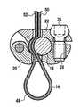
- FIG. 1is a perspective view of a first embodiment of a vertebral fixing system
- FIGS. 2A , 2 B, and 2 Care vertical section views of the fixing system showing the use of said system as shown in FIG. 1 ;
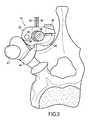
- FIG. 3is a face view showing the FIG. 1 fixing system put into place on a vertebra
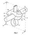
- FIG. 4is a perspective view of a second embodiment of the fixing system, the ligature not being shown;
- FIG. 5is an exploded view of the connection device of FIG. 4 ;
- FIG. 6is a plan view of a portion of the FIG. 1 connection device
- FIG. 6Ais a section view on line AA of FIG. 6 ;
- FIG. 7is a face view of the fixing system of the second embodiment.
- FIGS. 7A and 7Bare section views on line VII-VII of FIG. 7 showing two ways in which the flexible ligature can be put into place.
- the vertebral fixing systemcomprises a connecting part 12 , a flexible ligature 14 , and adjustable locking means 16 .
- the flexible ligature 14is of elongate shape and is capable of matching the outline of the parts it is to connect together.
- the rod 18that is to be secured to the vertebra by means of the vertebral fixing system.
- the connecting part 12is constituted by two longitudinal elements given respective references 20 and 22 , each having a first end 22 a , 20 a and a second end 22 b , 20 b.
- the longitudinal elements 20 and 22are hinged to each other at their second ends 20 b , 22 b about a pivot pin 24 .
- the locking meansare constituted by a screw 26 having a head 26 a that is engaged in a bore 28 formed in the first end 22 a of the longitudinal element 22 .
- the first end 20 a of the longitudinal element 20is pierced by a tapped bore 28 for co-operating with the threaded shank 26 b of the screw 26 .
- Each longitudinal element 20 , 22has an outside face 20 c , 22 c and an inside face 20 d , 22 d .
- the longitudinal elements 20 and 22are mounted in such a manner that the inside faces 20 d , 22 d of the longitudinal elements face each other.
- the inside faces 20 d , 22 d of the longitudinal elements 20 and 22have respective mutually-facing recesses 30 and 32 , each of substantially semicylindrical shape.
- the recesses 30 and 32define walls 34 and 36 which are ruled surfaces having generator lines parallel to the pivot axis 24 .
- slots 38 and 40cause the bottoms of the recesses 30 and 32 to communicate with the outside faces 20 c and 22 c of the longitudinal elements 20 and 22 .
- the recesses 30 and 32are for receiving the rod 18 together with a strand of the ligature 14 , the slots 38 and 40 serving to pass the ligature 14 .
- FIG. 2Athere can be seen the longitudinal elements 20 and 22 in the spaced-apart position, a position in which the locking means 16 are naturally not active, the threaded shank 26 b of the screw 26 not being engaged in the bore 28 .
- the ligature 14is engaged in the slots 38 and 40 of the longitudinal elements against one portion of the inside wall 34 , 36 of the recesses 30 and 32 .
- the rod 18is then introduced into the recess 30 of the longitudinal element 20 so that the two strands 42 and 44 of the ligature 14 are disposed between the inside wall of the recesses 30 and 32 and the side face 18 a of the rod 18 .
- These two surfacesdefine a passageway 46 for passing the ligature 14 and having the strands 42 and 44 of the ligature 14 placed therein.
- the strands 42 and 44 of the ligaturedefine a portion of the ligature 14 that forms a loop 48 that extends beyond the outside face 20 c of the longitudinal element 20 , and also two free portions 50 and 52 that extend beyond the outside face 22 c of the longitudinal element 22 .
- the ligature 14can slide freely along the passageway 46 .
- the surgeonengages the threaded shank 26 b of the screw 26 in the tapped bore 28 , causing the longitudinal element 22 to come progressively closer to the longitudinal element 20 .
- This approachsimultaneously reduces the section of the passageway 46 in which the strands 42 and 44 of the ligature are engaged and simultaneously introduces a certain coefficient of friction between the ligature and respectively the rod 18 and the walls of the recesses 30 and 32 . Nevertheless, it is still possible for the surgeon to extract traction on the free ends 50 and 52 of the ligature 14 until sufficient tension is obtained in the ligature around the vertebral process.
- both of the strands 42 and 44 of the ligatureare disposed in the recesses 30 and 32 on the same side of the rod 18 .
- This dispositionserves to obtain an optimum result. Nevertheless, it would not go beyond the invention if the strands 42 and 44 of the ligature 14 were to be placed on opposite sides of the rod 18 . Under such circumstances, it should be considered that the outside face 18 a of the rod 18 and the inside walls of the recesses 30 and 32 define two passageways, respectively for passing each of the strands 42 and 44 of the ligature 14 .
- FIGS. 4 to 7Bshow a second embodiment of the fixing system.
- the connecting part 12 ′is constituted by a part 50 that is generally U-shaped.
- the inside wall of this partis constituted by a bottom 52 of substantially semicylindrical shape and by two substantially plane portions 54 and 56 that correspond to the two limbs of the part 50 .
- the width l of the recess 58 formed in the part 50is substantially equal to the diameter d of the rod 18 .
- On its outside face 50 awhich is circularly symmetrical about a longitudinal axis of the part 50 , there is provided a thread 60 occupying its upper portion.
- the thread 60is located entirely above the rod 18 when it is put into place in the recess 58 .
- the thread 60is designed to co-operate with a clamping ring 62 that constitutes the adjustable locking means.
- This ringhas a slightly frustoconical bore 64 with an inside face 66 that carries tapping 68 .
- the part 50includes in its bottom 70 a passage 72 for passing the ligature 14 in a manner explained below.
- FIGS. 7 , 7 A, and 7 Bthere follows a description of two different ways of putting the flexible ligature 14 into place inside the connecting part 12 ′ in the second embodiment.
- the side wall of the rod 18 and the inside wall of the recess 58 of the part 50potentially define two passageways 74 and 76 for passing the middle strands of the flexible ligature 14 .
- FIG. 7AIn the configuration shown in FIG. 7A , only the passageway 74 is used.
- both intermediate strands 42 and 44 of the flexible ligature 14are disposed in the passage 74 . This disposition presents all of the advantages described with reference to the first embodiment.
- the middle strands 42 and 44 of the flexible ligature 14are disposed respectively one in each of the passageways 76 and 78 , i.e. on either side of the rod 18 .
- This configurationlikewise presents all of the advantages described with reference to the first embodiment of the device since the free ends 50 and 52 of the ligature 14 are accessible for exerting the desired traction in order to obtain suitable clamping on the spinous process prior to locking the clamping ring 62 on the part 52 .
- This second embodimentpresents the advantage of being simpler in design since it serves in particular to avoid making two longitudinal parts constituting a kind of clamp hinged on the pin 24 .
- the locking meansare constituted by an element that is distinct from the connecting part and that is removable therefrom.
- the locking meansco-operate with the connecting part by screw engagement. It is thus possible to adjust accurately the dimensions of the ligature-passing passageway(s) as defined by the connecting part and the rod.
- the coefficient of friction between the coefficient of the ligature and secondly the rod and the connecting partcan be adjusted.
- very effective clamping of the ligatureis obtained between the rod and the locking part.
Landscapes
- Health & Medical Sciences (AREA)
- Orthopedic Medicine & Surgery (AREA)
- Life Sciences & Earth Sciences (AREA)
- Neurology (AREA)
- Surgery (AREA)
- Heart & Thoracic Surgery (AREA)
- General Health & Medical Sciences (AREA)
- Biomedical Technology (AREA)
- Nuclear Medicine, Radiotherapy & Molecular Imaging (AREA)
- Medical Informatics (AREA)
- Molecular Biology (AREA)
- Animal Behavior & Ethology (AREA)
- Engineering & Computer Science (AREA)
- Public Health (AREA)
- Veterinary Medicine (AREA)
- Surgical Instruments (AREA)
- Prostheses (AREA)
- Details Of Connecting Devices For Male And Female Coupling (AREA)
- Supports For Pipes And Cables (AREA)
Abstract
Description
This application is a continuation of U.S. patent application Ser. No. 12/375,265, filed on Mar. 9, 2009 now U.S. Pat. No. 8,172,843, which is a U.S. National Phase Entry of International Application No. PCT/FR2006/050898, filed Sep. 18, 2006, which claims priority to French Application Nos. FR 0650609, filed Feb. 22, 2006 and FR 0509570, filed Sep. 20, 2005, the entire disclosures of which are incorporated herein by reference.
The present invention relates to vertebral fixing system suitable for being mounted on a vertebra.
An intended field of application is particularly, but not exclusively, the treatment of scoliosis, or more generally correcting abnormal curvatures of the spine.
The spine is constituted by superposed vertebrae that are normally in alignment along a vertical axis, going from the lumbar vertebrae to the cervical vertebrae, each vertebra presenting a posterior wall from which there projects a spinous process and two sides having walls from which there project the ribs and/or transverse processes. When the spine of an individual presents abnormal curvature, the vertebrae are inclined relative to one another and relative to said vertebral axis. The sides of the vertebrae situated on one side are thus moved closer together forming a concave side, whereas the sides of the vertebrae on the other side are spaced apart from one another and form a convex side.
In order to straighten the spinal column, the sides of the vertebrae on the concave side are spaced apart from one another and moved relative to one another to distances that are substantially equivalent to those between the sides of the vertebrae on the other side. In order to keep the vertebrae in that relative positioning, known devices have screws that are inserted in the vertebrae or hooks that are inserted along the inside wall of the vertebral canal, and rods that are for interconnecting the screws or the hooks.
The hooks are generally inserted in pairs into each vertebra and on either side close to the pedicles, with their heads projecting from the posterior wall of the vertebra, one on either side of the spinous process. By way of example, the heads form a socket suitable for receiving a rod that is held in place by means of a nut screwed onto the head so as to press against the rod. The rows constituted by the heads of the hooks situated on either side of the spinous processes are interconnected and held in a fixed position by two rods that are parallel to each other and to the axis of the spine.
Nevertheless, it is difficult to use such hooks since the operator must under no circumstances interfere with the spinal cord that extends along the center of the vertebral canal, since otherwise there is a danger of paralyzing the patient.
The use of screws makes it possible to diminish the risks of the operation. The screws likewise have socket-forming heads and they are inserted in pairs into the posterior walls of the vertebrae in the pedicles on either side of the spinous process. Thus, the screws constitute points for fixing the vertebrae so as to hold them relative to one another. Nevertheless, they are necessarily introduced into the pedicles of the vertebrae, and under certain circumstances such pedicles can be small in size or damaged.
The problem that arises and that the present invention seeks to solve is how to establish fixing points when it is not possible to introduce screws into the vertebrae in the curved portion of the spine and when the use of hooks is too dangerous. PCT patent application WO 2004/010881 in the name of the Applicant describes a vertebral fixing system that enables the problem to be solved.
That vertebral fixing system adapted to be mounted on a vertebra of the spine to connect it to a rod comprises:
a connecting part placed facing said rib and/or said transverse process and suitable for being connected to said rod;
an elongate flexible ligature suitable for connecting together said connecting part and at least one rib and/or one transverse process; and
adjustable locking means fastened to said connecting part, said ligature having a first end secured to said connecting part and a free second end suitable for sliding in said connecting part to form a loop, said locking means being suitable for holding in a fixed position both said connecting part relative to said rod, and a length of said ligature between said ends that is suitable for being prevented from moving in translation relative to said connecting part by said adjustable locking means, whereby the loop presents a length that is determined so as to prevent relative displacement of said rod and said vertebra in opposite directions.
That system is satisfactory, but under certain circumstances it can present the following drawback. When the surgeon exerts traction on the free end of the flexible ligature, the ligature can be jammed by friction against the bottom face of the process. Under such circumstances, it will be understood that although the length of the ligature between the bottom face of the process and the zone where traction is applied to the ligature is indeed under tension, the length that extends between the end of the ligature that is secured to the elongate passageway and the bottom face of the process is not under tension. Thus, overall, the ligature does not perform its function of fastening to the vertebra in appropriate manner.
An object of the present invention is to provide a vertebral fixing system that enables the above-mentioned drawbacks to be avoided and that provides controlled locking of the ligature.
According to the invention, to achieve this object, the vertebral fixing system suitable for being mounted on a vertebra of the spine in order to connect it to a rod comprises:
a connecting part presenting first and second sides and suitable for being connected to said rod;
a flexible ligature of elongate shape suitable for connecting together said connecting part and at least one rib and/or transverse process and/or a portion of the posterior arc of a vertebra; and
adjustable locking means mounted on said connecting part;
and said system is characterized in that:
said ligature presents two free ends;
said connecting part defines at least one passageway for passing said ligature in such a manner that two distinct strands of said ligature can be engaged in said passageway(s) so that said two ligature strands define a first ligature portion forming a loop that extends from a first side of said connecting part, and second and third ligature portions extending from the other side of said connecting part between respective ones of said ligature strands and said free ends; and
said locking means are distinct from the connecting part and co-operate therewith by screw-fastening, said locking means being capable of taking a first position relative to the connecting part in which the two ligature strands are free in said strand-passing passageway(s), a second position relative to the connecting part in which the two ligature strands are prevented from moving in translation relative to the connecting part, and intermediate positions in which a coefficient of friction is created between said ligature strands and said connecting part.
It will be understood that because the two ligature strands that are on either side of the transverse process are both placed in one or more passageways, when the locking means are brought into their locking position, both ligature strands can be used to exert the tension needed for fixing to the vertebra by means of a rib and/or a portion of the posterior arc of a vertebra and/or a transverse process.
In addition, since the locking means co-operate with the connecting part by screw-fastening, the “dimensions” of the passageways can be defined accurately during the various stages of clamping and then locking the ligature.
Preferably, the connecting part defines a single passageway and both ligature strands are engaged in the single passageway.
Also preferably, the single passageway is defined firstly by the outside surface of the portion of the rod that is engaged in the connecting part and secondly by a wall of the connecting part, and the locking means are suitable for modifying the section of the passageway.
When the locking means are in their second position, this ensures effective clamping of the two ligature strands, thereby preventing them from moving.
In a first embodiment, the connecting part comprises two longitudinal elements having first ends that are hinged together, each of said longitudinal elements presenting a recess suitable for receiving a portion of a section of said rod, a wall of said recess co-operating with the side surface of said rod to define said passageway for passing said ligature strands, said locking means being mounted at the two second ends of said longitudinal elements.
In a second embodiment, the connecting part comprises a part that is generally U-shaped, suitable for receiving said rod, and having the outer ends of the limbs of the U-shape threaded, and the adjustable locking means comprise a tapped ring suitable for co-operating with the thread on the U-shaped part, tightening the ring causing the limbs of the part to be clamped against the rod.
Preferably, said passageway(s) is/are constituted by the space between the inside wall of the recess formed in said connecting part and the side wall of said rod.
Other characteristics and advantages of the invention appear better on reading the following description of embodiments of the invention given by way of non-limiting example. The description refers to the accompanying figures, in which:
As shown inFIG. 1 , in the first embodiment, the vertebral fixing system comprises a connectingpart 12, aflexible ligature 14, and adjustable locking means16. Theflexible ligature 14 is of elongate shape and is capable of matching the outline of the parts it is to connect together. In this figure, there can also be seen therod 18 that is to be secured to the vertebra by means of the vertebral fixing system. In the first embodiment, the connectingpart 12 is constituted by two longitudinal elements givenrespective references first end second end
As can be seen better inFIG. 2A , thelongitudinal elements pivot pin 24.
In the embodiment described, the locking means are constituted by ascrew 26 having ahead 26athat is engaged in abore 28 formed in thefirst end 22aof thelongitudinal element 22. Thefirst end 20aof thelongitudinal element 20 is pierced by a tapped bore28 for co-operating with the threadedshank 26bof thescrew 26. Eachlongitudinal element outside face inside face longitudinal elements longitudinal elements recesses recesses walls 34 and36 which are ruled surfaces having generator lines parallel to thepivot axis 24. Finally,slots recesses longitudinal elements recesses rod 18 together with a strand of theligature 14, theslots ligature 14.
With reference toFIGS. 2A to 2C , there follows an explanation of how the fixing system is used.
InFIG. 2A , there can be seen thelongitudinal elements shank 26bof thescrew 26 not being engaged in thebore 28. Theligature 14 is engaged in theslots inside wall 34,36 of therecesses rod 18 is then introduced into therecess 30 of thelongitudinal element 20 so that the twostrands ligature 14 are disposed between the inside wall of therecesses rod 18. These two surfaces define apassageway 46 for passing theligature 14 and having thestrands ligature 14 placed therein.
As shown better inFIG. 2B , thestrands ligature 14 that forms aloop 48 that extends beyond theoutside face 20cof thelongitudinal element 20, and also twofree portions outside face 22cof thelongitudinal element 22. When thelongitudinal elements FIG. 2B , theligature 14 can slide freely along thepassageway 46. Once theportion 48 of theligature 14 forming the loop is placed around the transverse process or a rib or indeed a portion of the posterior arc of a vertebra, the surgeon engages the threadedshank 26bof thescrew 26 in the tapped bore28, causing thelongitudinal element 22 to come progressively closer to thelongitudinal element 20. This approach simultaneously reduces the section of thepassageway 46 in which thestrands rod 18 and the walls of therecesses ligature 14 until sufficient tension is obtained in the ligature around the vertebral process. Once the tension in the ligature is sufficient for providing appropriate fastening, the surgeon finishes off tightening thescrew 26 in the tapped bore28, thus locking thelongitudinal elements strands rod 18 and the wall of therecesses
In this locking position, therod 18 is thus secured to theligature 14 via the connectingpart 12.
It will also be understood that because the surgeon exerts traction only on the free ends50 and52 of theligature 14, there is no risk of jamming between theligature 14 and the bottom face of the transverse process or of the rib, thus guaranteeing that effective fastening is provided with the transverse process or the rib or indeed a portion of the posterior arc of a vertebra.
This is shown inFIG. 3 , where reference AT identifies the transverse process.
In the above description, both of thestrands recesses rod 18. This disposition serves to obtain an optimum result. Nevertheless, it would not go beyond the invention if thestrands ligature 14 were to be placed on opposite sides of therod 18. Under such circumstances, it should be considered that theoutside face 18aof therod 18 and the inside walls of therecesses strands ligature 14.
In these figures, there can be seen therod 18, the connecting part now referenced12′, and theflexible ligature 14.
In this embodiment, the connectingpart 12′ is constituted by apart 50 that is generally U-shaped. The inside wall of this part is constituted by a bottom52 of substantially semicylindrical shape and by two substantially planeportions part 50. The width l of therecess 58 formed in thepart 50 is substantially equal to the diameter d of therod 18. On itsoutside face 50awhich is circularly symmetrical about a longitudinal axis of thepart 50, there is provided athread 60 occupying its upper portion. Thethread 60 is located entirely above therod 18 when it is put into place in therecess 58. Thethread 60 is designed to co-operate with a clampingring 62 that constitutes the adjustable locking means. This ring has a slightlyfrustoconical bore 64 with aninside face 66 that carries tapping68.
It can thus be understood that when thering 62 is screwed tight on the threadedportion 60 of thepart 50, it deforms the limbs of thepart 50 elastically, thereby pinching and clamping strands of theligature 14 between therod 18 and the inside wall(s) of therecess 58, in a manner explained below.
As shown better inFIGS. 6 and 6A , thepart 50 includes in its bottom70 apassage 72 for passing theligature 14 in a manner explained below.
With reference toFIGS. 7 ,7A, and7B, there follows a description of two different ways of putting theflexible ligature 14 into place inside the connectingpart 12′ in the second embodiment. The side wall of therod 18 and the inside wall of therecess 58 of thepart 50 potentially define twopassageways flexible ligature 14. In the configuration shown inFIG. 7A , only thepassageway 74 is used. Thus, bothintermediate strands flexible ligature 14 are disposed in thepassage 74. This disposition presents all of the advantages described with reference to the first embodiment.
In the configuration shown inFIG. 7B , themiddle strands flexible ligature 14 are disposed respectively one in each of thepassageways rod 18. This configuration likewise presents all of the advantages described with reference to the first embodiment of the device since the free ends50 and52 of theligature 14 are accessible for exerting the desired traction in order to obtain suitable clamping on the spinous process prior to locking the clampingring 62 on thepart 52.
This second embodiment presents the advantage of being simpler in design since it serves in particular to avoid making two longitudinal parts constituting a kind of clamp hinged on thepin 24.
It will be understood that in both embodiments, the locking means are constituted by an element that is distinct from the connecting part and that is removable therefrom. In addition, in both cases, the locking means co-operate with the connecting part by screw engagement. It is thus possible to adjust accurately the dimensions of the ligature-passing passageway(s) as defined by the connecting part and the rod. In an initial stage, the coefficient of friction between the coefficient of the ligature and secondly the rod and the connecting part can be adjusted. In the final stage, very effective clamping of the ligature is obtained between the rod and the locking part.
Claims (20)
1. A bone fixing system for engaging a bone, comprising:
a connecting part comprising:
a first opening;
a second opening;
a transverse passage sized to receive a rod therethrough; and
a bore hole;
a flexible ligature comprising:
a first end portion extendable from the first opening of the connecting part in a first direction;
a second end portion extendable from the first opening of the connecting part in the first direction with the first end portion; and
a loop portion between the first end portion and the second end portion, the loop portion extendable from the second opening of the connecting part; and
an adjustable locking member configured for engagement with the bore hole of the connecting part to lock the flexible ligature relative to the connecting part, wherein first and second portions of the flexible ligature are pressed directly against each other within the connecting part when the ligature is locked relative to the connecting part.
2. A bone fixing system according toclaim 1 , wherein the connecting part is configured to be secured to a rod extending through the transverse passage, such that the rod presses directly against one of the first and second portions of the flexible ligature thereby locking the first and second portions of the flexible ligature between the rod and an inner wall of the connecting part.
3. A bone fixing system according toclaim 1 , wherein the loop portion of the flexible ligature is sized to pass around a bony element.
4. A bone fixing system according toclaim 1 , wherein the first opening of the connecting part and the second opening of the connecting part are positioned on opposite sides of the connecting part.
5. A bone fixing system according toclaim 1 , wherein the adjustable locking member is configured to engage with the bore hole of the connecting part in a plurality of positions relative to the connecting part.
6. A bone fixing system according toclaim 5 , wherein the plurality of positions of the adjustable locking member relative to the connecting part comprises:
a first position in which the flexible ligature is free to move within the first and second opening; and
a second position in which the flexible ligature is prevented from moving in translation relative to the connecting part.
7. A bone fixing system according toclaim 6 , wherein the plurality of positions of the adjustable locking member relative to the connecting part further comprises intermediate positions between the first position and the second position in which a coefficient of friction is created between a portion of the flexible ligature and the connecting part.
8. A bone fixing system according toclaim 1 , wherein the first opening of the connecting part is positioned near the bore hole of the connecting part.
9. A bone fixing system according toclaim 1 , wherein the adjustable locking member cooperates with the connecting part by screw-fastening.
10. A bone fixing system according toclaim 9 , wherein the adjustable locking member comprises a screw.
11. A bone fixing system according toclaim 10 , wherein tightening the screw relative to the bore hole of the connecting part locks the flexible ligature in place.
12. A bone fixing system according toclaim 11 , wherein locking the flexible ligature in place prevents any additional portion of the flexible ligature from becoming part of the loop portion of the flexible ligature, thereby defining a size of the loop portion of the flexible ligature.
13. A method for engaging a bone, comprising:
advancing a rod through a transverse passage of a connecting part;
passing a portion of a flexible ligature through the connecting part to form a loop such that a first end portion of the flexible ligature and a second end portion of the flexible ligature both extend from a first opening of the connecting part in a first direction, first and second portions of the flexible ligature are pressed directly against each other within the connecting part, and the loop extends from a second opening of the connecting part; and
engaging an adjustable locking member with a bore hole of the connecting part to provide controlled locking of the flexible ligature relative to the connecting part.
14. A method according toclaim 13 , further comprising securing the connecting part to the rod extending through the transverse passage of the connecting part such that the rod presses directly against one of the first and second portions of the flexible ligature.
15. A method according toclaim 13 , further comprising placing the portion of the flexible ligature around a bony element.
16. A method according toclaim 15 , further comprising extracting traction on the at least one end of the flexible ligature until sufficient tension is obtained in the portion of the flexible ligature placed around the bony element.
17. A method according toclaim 16 , further comprising tightening the adjustable locking member in the bore hole of the connecting part, locking of the flexible ligature relative to the connecting part.
18. A method according toclaim 13 , wherein the adjustable locking member comprises a screw and wherein engaging the adjustable locking member with the bore hole of the connecting part further comprises threading the screw relative to the bore hole of the connecting part.
19. A method according toclaim 18 , wherein tightening the screw causes the connecting part to create a force against the flexible ligature.
20. A method according toclaim 19 , wherein the force against the flexible ligature prevents any additional portion of the flexible ligature from becoming part of the loop, thereby defining a size of the loop.
Priority Applications (3)
| Application Number | Priority Date | Filing Date | Title |
|---|---|---|---|
| US13/248,453US8870870B2 (en) | 2005-09-20 | 2011-09-29 | Vertebral fixing system |
| US14/511,739US9113966B2 (en) | 2005-09-20 | 2014-10-10 | Vertebral fixing system |
| US14/796,472US9717536B2 (en) | 2005-09-20 | 2015-07-10 | Vertebral fixing system |
Applications Claiming Priority (7)
| Application Number | Priority Date | Filing Date | Title |
|---|---|---|---|
| FR0509570AFR2890849A1 (en) | 2005-09-20 | 2005-09-20 | Vertebral fixing system for e.g. scoliosis treatment, has connection part defining through path for elongated flexible link such that portions of link are engaged with path for defining link part and free ends |
| FR0509570 | 2005-09-20 | ||
| FR0650609 | 2006-02-22 | ||
| FR0650609AFR2890850B1 (en) | 2005-09-20 | 2006-02-22 | VERTEBRAL FASTENING SYSTEM |
| PCT/FR2006/050898WO2007036657A1 (en) | 2005-09-20 | 2006-09-18 | Vertebral fixing system |
| US12/375,265US8172843B2 (en) | 2005-09-20 | 2006-09-18 | Vertebral fixing system |
| US13/248,453US8870870B2 (en) | 2005-09-20 | 2011-09-29 | Vertebral fixing system |
Related Parent Applications (3)
| Application Number | Title | Priority Date | Filing Date |
|---|---|---|---|
| US11/375,265ContinuationUS7887538B2 (en) | 2004-10-15 | 2006-03-13 | Methods and apparatus for tissue modification |
| PCT/FR2006/050898ContinuationWO2007036657A1 (en) | 2005-09-20 | 2006-09-18 | Vertebral fixing system |
| US12/375,265ContinuationUS8172843B2 (en) | 2005-09-20 | 2006-09-18 | Vertebral fixing system |
Related Child Applications (1)
| Application Number | Title | Priority Date | Filing Date |
|---|---|---|---|
| US14/511,739ContinuationUS9113966B2 (en) | 2005-09-20 | 2014-10-10 | Vertebral fixing system |
Publications (2)
| Publication Number | Publication Date |
|---|---|
| US20120022591A1 US20120022591A1 (en) | 2012-01-26 |
| US8870870B2true US8870870B2 (en) | 2014-10-28 |
Family
ID=37654917
Family Applications (5)
| Application Number | Title | Priority Date | Filing Date |
|---|---|---|---|
| US12/375,265Expired - Fee RelatedUS8172843B2 (en) | 2005-09-20 | 2006-09-18 | Vertebral fixing system |
| US13/248,453Active2027-07-06US8870870B2 (en) | 2005-09-20 | 2011-09-29 | Vertebral fixing system |
| US13/443,206ActiveUS8430918B2 (en) | 2005-09-20 | 2012-04-10 | Vertebral fixing system |
| US14/511,739Expired - Fee RelatedUS9113966B2 (en) | 2005-09-20 | 2014-10-10 | Vertebral fixing system |
| US14/796,472ActiveUS9717536B2 (en) | 2005-09-20 | 2015-07-10 | Vertebral fixing system |
Family Applications Before (1)
| Application Number | Title | Priority Date | Filing Date |
|---|---|---|---|
| US12/375,265Expired - Fee RelatedUS8172843B2 (en) | 2005-09-20 | 2006-09-18 | Vertebral fixing system |
Family Applications After (3)
| Application Number | Title | Priority Date | Filing Date |
|---|---|---|---|
| US13/443,206ActiveUS8430918B2 (en) | 2005-09-20 | 2012-04-10 | Vertebral fixing system |
| US14/511,739Expired - Fee RelatedUS9113966B2 (en) | 2005-09-20 | 2014-10-10 | Vertebral fixing system |
| US14/796,472ActiveUS9717536B2 (en) | 2005-09-20 | 2015-07-10 | Vertebral fixing system |
Country Status (7)
| Country | Link |
|---|---|
| US (5) | US8172843B2 (en) |
| EP (1) | EP1926444B2 (en) |
| JP (1) | JP2009508609A (en) |
| AT (1) | ATE549985T1 (en) |
| AU (1) | AU2006296410B2 (en) |
| FR (1) | FR2890850B1 (en) |
| WO (1) | WO2007036657A1 (en) |
Cited By (16)
| Publication number | Priority date | Publication date | Assignee | Title |
|---|---|---|---|---|
| US9241739B2 (en) | 2008-09-12 | 2016-01-26 | DePuy Synthes Products, Inc. | Spinal stabilizing and guiding fixation system |
| US9717536B2 (en) | 2005-09-20 | 2017-08-01 | Zimmer Spine S.A.S. | Vertebral fixing system |
| US9848918B2 (en) | 2005-11-21 | 2017-12-26 | DePuy Synthes Products, Inc. | Polyaxial bone anchors with increased angulation |
| US9924976B2 (en) | 2015-09-24 | 2018-03-27 | Warsaw Orthopedic, Inc. | Spinal implant system and method |
| US10105163B2 (en) | 2009-04-15 | 2018-10-23 | DePuy Synthes Products, Inc. | Revision connector for spinal constructs |
| US10136923B2 (en) | 2007-07-20 | 2018-11-27 | DePuy Synthes Products, Inc. | Polyaxial bone fixation element |
| US10154859B2 (en) | 2008-09-29 | 2018-12-18 | DePuy Synthes Products, Inc. | Polyaxial bottom-loading screw and rod assembly |
| US10307186B2 (en) | 2016-12-02 | 2019-06-04 | Nuvasive, Inc. | Surgical band clamp system |
| US10405892B2 (en) | 2008-11-03 | 2019-09-10 | DePuy Synthes Products, Inc. | Uni-planer bone fixation assembly |
| US11006978B2 (en) | 2009-06-17 | 2021-05-18 | DePuy Synthes Products, Inc. | Revision connector for spinal constructs |
| US11051857B2 (en) | 2017-08-10 | 2021-07-06 | Ortho Development Corporation | Tether clamping assemblies and related methods and apparatus |
| US11071569B2 (en) | 2017-08-10 | 2021-07-27 | Ortho Development Corporation | Nesting tether clamping assemblies and related methods and apparatus |
| US11116550B2 (en) | 2019-04-26 | 2021-09-14 | Warsaw Orthopedic, Inc. | Spinal implant system and method |
| US11284924B1 (en) | 2020-12-16 | 2022-03-29 | Warsaw Orthopedic, Inc | Adjustable spinal implant, system and method |
| US11350969B1 (en) | 2021-02-02 | 2022-06-07 | Warsaw Orthopedic, Inc. | Rotatable spinal implant, system, and method |
| US11819255B2 (en) | 2019-10-07 | 2023-11-21 | Ortho Development Corporation | Tether tensioning instrumentation and related methods |
Families Citing this family (70)
| Publication number | Priority date | Publication date | Assignee | Title |
|---|---|---|---|---|
| FR2812185B1 (en) | 2000-07-25 | 2003-02-28 | Spine Next Sa | SEMI-RIGID CONNECTION PIECE FOR RACHIS STABILIZATION |
| FR2812186B1 (en) | 2000-07-25 | 2003-02-28 | Spine Next Sa | FLEXIBLE CONNECTION PIECE FOR SPINAL STABILIZATION |
| FR2842724B1 (en) | 2002-07-23 | 2005-05-27 | Spine Next Sa | VERTEBRAL FASTENING SYSTEM |
| FR2890851B1 (en) | 2005-09-21 | 2008-06-20 | Abbott Spine Sa | ANCILLARY TO TENSION A FLEXIBLE LINK. |
| WO2007121271A2 (en) | 2006-04-11 | 2007-10-25 | Synthes (U.S.A) | Minimally invasive fixation system |
| EP2047813A1 (en)* | 2007-10-11 | 2009-04-15 | Abbott Spine | Bone fixing system and method of use |
| JP5087081B2 (en)* | 2007-05-11 | 2012-11-28 | トヨタ自動車株式会社 | Side impact airbag control device |
| CA2694010C (en)* | 2007-07-19 | 2015-04-21 | Synthes Usa, Llc | Clamps used for interconnecting a bone anchor to a rod |
| WO2009013397A1 (en)* | 2007-07-25 | 2009-01-29 | Ros Guillen, Francisco | Vertebral fastening device for a system for correcting the abnormal curvatures of the rachis |
| US20090093819A1 (en)* | 2007-10-05 | 2009-04-09 | Abhijeet Joshi | Anisotropic spinal stabilization rod |
| ATE536824T1 (en)* | 2007-10-23 | 2011-12-15 | Zimmer Spine | FASTENING DEVICES AND STABILIZATION SYSTEMS WITH THESE FASTENING DEVICES |
| US8128635B2 (en) | 2007-10-23 | 2012-03-06 | Zimmer Spine S.A.S. | Bone fixation tensioning tool and method |
| US20090248077A1 (en)* | 2008-03-31 | 2009-10-01 | Derrick William Johns | Hybrid dynamic stabilization |
| ATE515239T1 (en) | 2008-04-24 | 2011-07-15 | Zimmer Spine | SYSTEM FOR STABILIZING AT LEAST ONE SECTION OF THE SPINE |
| EP2303163B1 (en) | 2008-05-20 | 2011-11-23 | Zimmer Spine | System for stabilizing at least three vertebrae |
| FR2931654B1 (en) | 2008-05-27 | 2011-12-16 | Medicrea International | MATERIAL OF VERTEBRAL OSTEOSYNTHESIS |
| US8231626B2 (en) | 2009-05-12 | 2012-07-31 | Synthes Usa, Llc | Self-retaining cable tie |
| CN102497828B (en) | 2009-05-20 | 2015-09-09 | 斯恩蒂斯有限公司 | What patient installed retracts part |
| EP2279707A1 (en) | 2009-07-31 | 2011-02-02 | Zimmer Spine | Bone fixing system |
| EP2316363A1 (en) | 2009-10-27 | 2011-05-04 | Zimmer Spine | Bone holding device |
| FR2954905B1 (en)* | 2010-01-06 | 2012-12-28 | Implanet | DEVICE FOR FIXING VERTEBRAL |
| US8535318B2 (en) | 2010-04-23 | 2013-09-17 | DePuy Synthes Products, LLC | Minimally invasive instrument set, devices and related methods |
| US20110301644A1 (en)* | 2010-06-08 | 2011-12-08 | Zimmer Spine | Spinal stabilization system |
| EP2422728B1 (en)* | 2010-08-25 | 2013-01-30 | Zimmer Spine | Anchor for attachment to a bony structure |
| EP2471476A1 (en)* | 2010-11-10 | 2012-07-04 | Zimmer Spine | Bone anchor |
| US9084644B2 (en) | 2011-02-02 | 2015-07-21 | DePuy Synthes Products, Inc. | Bone fixation assembly |
| US8740949B2 (en) | 2011-02-24 | 2014-06-03 | Spinal Elements, Inc. | Methods and apparatus for stabilizing bone |
| US8992579B1 (en)* | 2011-03-08 | 2015-03-31 | Nuvasive, Inc. | Lateral fixation constructs and related methods |
| CN103717159B (en) | 2011-05-27 | 2016-08-17 | 新特斯有限责任公司 | Minimally Invasive Spinal Fixation System Including Vertebral Alignment Features |
| FR2977138B1 (en)* | 2011-06-30 | 2014-02-28 | Implanet | DEVICE FOR FIXING VERTEBRAL |
| EP2734135B1 (en)* | 2011-07-21 | 2018-03-21 | Zimmer Spine | Spinal rod fixing device |
| US8636770B2 (en) | 2011-08-08 | 2014-01-28 | Zimmer Spine, Inc. | Bone anchoring device |
| WO2013040456A1 (en) | 2011-09-14 | 2013-03-21 | Band-Lok, Llc | Tether clamp and implantation system |
| USD739935S1 (en) | 2011-10-26 | 2015-09-29 | Spinal Elements, Inc. | Interbody bone implant |
| US9060815B1 (en) | 2012-03-08 | 2015-06-23 | Nuvasive, Inc. | Systems and methods for performing spine surgery |
| FR2988992B1 (en)* | 2012-04-04 | 2015-03-20 | Medicrea International | MATERIAL OF VERTEBRAL OSTEOSYNTHESIS |
| US8870881B2 (en) | 2012-04-06 | 2014-10-28 | Warsaw Orthopedic, Inc. | Spinal correction system and method |
| US8945188B2 (en) | 2012-04-06 | 2015-02-03 | William Alan Rezach | Spinal correction system and method |
| EP2668921B1 (en)* | 2012-06-01 | 2015-08-12 | Zimmer Spine | Device for fixing a bony structure to a support member |
| GB201220042D0 (en)* | 2012-11-07 | 2012-12-19 | Murray David W | Adjusting spinal curvature |
| US20140148854A1 (en) | 2012-11-28 | 2014-05-29 | Zimmer Spine, Inc. | Vertebral fixation system |
| EP2762095B1 (en) | 2013-01-31 | 2016-05-25 | Zimmer Spine | Device for fixing a bony structure to a support member |
| US10548644B2 (en) | 2013-03-05 | 2020-02-04 | Globus Medical, Inc. | Elastic member clamps |
| US9675386B2 (en) | 2013-03-11 | 2017-06-13 | K2M, Inc. | Flexible fastening system |
| US9421044B2 (en) | 2013-03-14 | 2016-08-23 | Spinal Elements, Inc. | Apparatus for bone stabilization and distraction and methods of use |
| US9456855B2 (en) | 2013-09-27 | 2016-10-04 | Spinal Elements, Inc. | Method of placing an implant between bone portions |
| US9839450B2 (en) | 2013-09-27 | 2017-12-12 | Spinal Elements, Inc. | Device and method for reinforcement of a facet |
| US9517089B1 (en) | 2013-10-08 | 2016-12-13 | Nuvasive, Inc. | Bone anchor with offset rod connector |
| FR3012032B1 (en) | 2013-10-18 | 2015-12-11 | Implanet | DEVICE AND SYSTEM FOR VERTICAL FASTENING FOR HOLDING A VERTEBRA ON A ROD, METHOD OF BLOCKING A LOOP WITH SUCH A DEVICE. |
| US9402666B2 (en) | 2014-04-30 | 2016-08-02 | King Faisal Specialist Hospital & Research Centre | Vertebral fixation device |
| US9603646B2 (en) | 2014-05-30 | 2017-03-28 | DePuy Synthes Products, Inc. | Bone fixation assembly |
| US11478275B2 (en)* | 2014-09-17 | 2022-10-25 | Spinal Elements, Inc. | Flexible fastening band connector |
| US9931138B2 (en) | 2014-10-15 | 2018-04-03 | Globus Medical, Inc. | Orthopedic extendable rods |
| AU2016212009C1 (en) | 2015-01-27 | 2021-02-25 | Spinal Elements, Inc. | Facet joint implant |
| US9795421B2 (en) | 2015-07-07 | 2017-10-24 | K2M, Inc. | Spinal construct with flexible member |
| EP3490474A4 (en) | 2016-07-26 | 2019-08-28 | Band-lok, LLC | ORTHOPEDIC IMPLANTS. |
| EP3525699B1 (en) | 2016-10-11 | 2023-07-26 | K2M, Inc. | Spinal implant |
| US10292737B2 (en) | 2017-06-07 | 2019-05-21 | Warsaw Orthopedic, Inc. | Spinal implant system and method |
| JP2019129951A (en)* | 2018-01-30 | 2019-08-08 | 富士フイルム株式会社 | Rib development image generation device, method, and program |
| US10568674B1 (en) | 2019-01-24 | 2020-02-25 | Syberspine Limited | Pedicle screws with integrated anchor for retaining artificial ligament tape used for posterior ligament reconstruction |
| US11185319B2 (en) | 2019-02-11 | 2021-11-30 | Warsaw Orthopedic, Inc. | Surgical distractor and method |
| BR112021022695A2 (en) | 2019-05-22 | 2021-12-28 | Spinal Elements Inc | Bone tethering and bone tethering inserter |
| US11457959B2 (en) | 2019-05-22 | 2022-10-04 | Spinal Elements, Inc. | Bone tie and bone tie inserter |
| US20210121203A1 (en)* | 2019-10-29 | 2021-04-29 | Globus Medical, Inc. | Sublaminar band clamp |
| WO2021163313A1 (en) | 2020-02-14 | 2021-08-19 | Spinal Elements, Inc. | Bone tie methods |
| CN112022318B (en)* | 2020-09-22 | 2022-05-13 | 常州集硕医疗器械有限公司 | Spinal deformity growth fixing system and method |
| EP4029464B1 (en) | 2021-01-15 | 2024-03-27 | NSpine GmbH | Spinal fixation system |
| US12369952B2 (en) | 2021-12-10 | 2025-07-29 | Spinal Elements, Inc. | Bone tie and portal |
| US12433644B2 (en) | 2022-11-17 | 2025-10-07 | Warsaw Orthopedic, Inc. | Multiaxial receivers with tether |
| US11877775B1 (en) | 2022-11-21 | 2024-01-23 | Warsaw Orthopedic, Inc. | Multiaxial receivers with tether |
Citations (95)
| Publication number | Priority date | Publication date | Assignee | Title |
|---|---|---|---|---|
| US902040A (en) | 1906-03-12 | 1908-10-27 | Homer W Wyckoff | Wire-connector. |
| US1346940A (en) | 1919-10-28 | 1920-07-20 | Asa W Collins | Apparatus for binding fractured bones |
| FR522040A (en) | 1920-08-07 | 1921-07-24 | Auguste Henri Contassot | Ligating device |
| US2049361A (en) | 1934-10-27 | 1936-07-28 | Ericsson Ernst Axel Johan | Wire or ribbon tightening apparatus |
| US4570618A (en) | 1983-11-23 | 1986-02-18 | Henry Ford Hospital | Intervertebral body wire stabilization |
| US5030220A (en) | 1990-03-29 | 1991-07-09 | Advanced Spine Fixation Systems Incorporated | Spine fixation system |
| GB2269753A (en) | 1992-08-19 | 1994-02-23 | Surgicarft Ltd | Surgical implants,tensioning tools and anchorage inserter |
| US5304178A (en) | 1992-05-29 | 1994-04-19 | Acromed Corporation | Sublaminar wire |
| WO1994016635A1 (en) | 1993-01-19 | 1994-08-04 | Jbs Sa | Spinal osteosynthesis device |
| US5356412A (en) | 1992-10-09 | 1994-10-18 | United States Surgical Corporation | Sternum buckle with rotational engagement and method of closure |
| FR2704745A1 (en) | 1993-05-07 | 1994-11-10 | Erpios | Device for connecting the ends of a ligament for osteosynthesis, in particular for vertebral osteosynthesis. |
| US5413576A (en) | 1993-02-10 | 1995-05-09 | Rivard; Charles-Hilaire | Apparatus for treating spinal disorder |
| US5449361A (en) | 1993-04-21 | 1995-09-12 | Amei Technologies Inc. | Orthopedic cable tensioner |
| FR2722088A1 (en) | 1994-07-08 | 1996-01-12 | Cahlik Marc Andre | Surgical implant for stabilising intervertebral spaces |
| US5609634A (en) | 1992-07-07 | 1997-03-11 | Voydeville; Gilles | Intervertebral prosthesis making possible rotatory stabilization and flexion/extension stabilization |
| EP0780096A1 (en) | 1995-12-22 | 1997-06-25 | Transystème S.A. | Binding strap for medical uses and fixing device |
| US5667508A (en) | 1996-05-01 | 1997-09-16 | Fastenetix, Llc | Unitary locking cap for use with a pedicle screw |
| US5669917A (en) | 1994-02-24 | 1997-09-23 | Lasersurge, Inc. | Surgical crimping device and method of use |
| US5702399A (en)* | 1996-05-16 | 1997-12-30 | Pioneer Laboratories, Inc. | Surgical cable screw connector |
| US5720751A (en) | 1996-11-27 | 1998-02-24 | Jackson; Roger P. | Tools for use in seating spinal rods in open ended implants |
| US5772663A (en) | 1994-02-17 | 1998-06-30 | Whiteside; Leo A. | Surgical device for banding bone with cable |
| DE19716504A1 (en) | 1997-04-19 | 1998-12-03 | Hinze Manfred Dr Med Habil | Compression hoop for applying metal band around bone |
| USRE36221E (en) | 1989-02-03 | 1999-06-01 | Breard; Francis Henri | Flexible inter-vertebral stabilizer as well as process and apparatus for determining or verifying its tension before installation on the spinal column |
| US5935133A (en) | 1997-08-26 | 1999-08-10 | Spinal Concepts, Inc. | Surgical cable system and method |
| US5938663A (en) | 1995-03-06 | 1999-08-17 | Stryker France, S.A. | Spinal instruments, particularly for a rod |
| US6053921A (en) | 1997-08-26 | 2000-04-25 | Spinal Concepts, Inc. | Surgical cable system and method |
| US6086590A (en) | 1999-02-02 | 2000-07-11 | Pioneer Laboratories, Inc. | Cable connector for orthopaedic rod |
| US6099527A (en) | 1998-04-30 | 2000-08-08 | Spinal Concepts, Inc. | Bone protector and method |
| US6146386A (en) | 1999-02-04 | 2000-11-14 | Sdgi Holdings, Inc. | Cable operated bone anchor compressor |
| US6179838B1 (en) | 1998-02-24 | 2001-01-30 | Daniel Fiz | Bone fixation arrangements and method |
| FR2799948A1 (en) | 1999-10-22 | 2001-04-27 | Transco Esquisse | Connecting bar esp for lumbar arthrodesis has lateral rod fixings and central anchor for interspinal prosthesis |
| US6228096B1 (en) | 1999-03-31 | 2001-05-08 | Sam R. Marchand | Instrument and method for manipulating an operating member coupled to suture material while maintaining tension on the suture material |
| US6241740B1 (en) | 1998-04-09 | 2001-06-05 | Origin Medsystems, Inc. | System and method of use for ligating and cutting tissue |
| WO2001054599A1 (en) | 2000-01-31 | 2001-08-02 | Sven Olerud | Locking device and method for using this device |
| US6277120B1 (en) | 2000-09-20 | 2001-08-21 | Kevin Jon Lawson | Cable-anchor system for spinal fixation |
| US6299613B1 (en) | 1999-04-23 | 2001-10-09 | Sdgi Holdings, Inc. | Method for the correction of spinal deformities through vertebral body tethering without fusion |
| US6309390B1 (en) | 1997-04-04 | 2001-10-30 | Stryker France S.A. | Device for backbone osteosynthesis with offset intervertebral fixing rod |
| JP2001299770A (en) | 2000-04-20 | 2001-10-30 | Azwell Inc | Clip for bone fixing string |
| WO2002007621A1 (en) | 2000-07-25 | 2002-01-31 | Spine Next | Semirigid linking piece for stabilising the spine |
| WO2002007622A1 (en) | 2000-07-25 | 2002-01-31 | Spine Next | Flexible linking piece for stabilising the spine |
| WO2002009604A1 (en) | 2000-08-02 | 2002-02-07 | Depuy International Limited | Surgical fixings |
| US6352557B1 (en) | 1999-08-13 | 2002-03-05 | Bret A. Ferree | Treating degenerative disc disease through transplantion of extracellular nucleus pulposus matrix and autograft nucleus pulposus cells |
| WO2002017803A2 (en) | 2000-09-01 | 2002-03-07 | Hôpital Sainte-Justine | Mobile dynamic system for treating spinal disorder |
| FR2817929A1 (en) | 2000-12-07 | 2002-06-14 | Spine Next Sa | DEVICE FOR FIXING A ROD AND A SPHERICAL SYMMETRY SCREW HEAD |
| WO2002051326A1 (en) | 2000-12-22 | 2002-07-04 | Spine Next | Intervertebral implant with deformable wedge |
| US6419702B1 (en) | 1999-08-13 | 2002-07-16 | Bret A. Ferree | Treating degenerative disc disease through transplantation of the nucleus pulposis |
| US20020116013A1 (en) | 2000-10-24 | 2002-08-22 | Gleason Joseph E. | Tension band clip |
| US6447518B1 (en) | 1995-07-18 | 2002-09-10 | William R. Krause | Flexible shaft components |
| WO2002071960A1 (en) | 2001-03-13 | 2002-09-19 | Spine Next | Self locking fixable intervertebral implant |
| US6478798B1 (en) | 2001-05-17 | 2002-11-12 | Robert S. Howland | Spinal fixation apparatus and methods for use |
| US20020198538A1 (en) | 2001-06-25 | 2002-12-26 | Kortenbach Juergen A. | Surgical device having a handle adapted to impart tensile and compressive forces to elements at a distal end of the device |
| WO2003007829A1 (en) | 2001-07-20 | 2003-01-30 | Spinal Concepts, Inc. | Spinal stabilization system and method |
| US6514255B1 (en)* | 2000-02-25 | 2003-02-04 | Bret Ferree | Sublaminar spinal fixation apparatus |
| US6547770B2 (en) | 2000-04-14 | 2003-04-15 | Aiolos Systems Aktiebolag (Ab) | Ophthalmic dispensing device |
| US6547790B2 (en) | 2000-08-08 | 2003-04-15 | Depuy Acromed, Inc. | Orthopaedic rod/plate locking mechanisms and surgical methods |
| US6569164B1 (en) | 1998-04-29 | 2003-05-27 | Stryker Spine | Spinal osteosynthesis system for anterior fixation |
| US6569171B2 (en) | 2001-02-28 | 2003-05-27 | Microline, Inc. | Safety locking mechanism for a medical clip device |
| US6605091B1 (en) | 2000-06-30 | 2003-08-12 | Pioneer Laboratories, Inc. | Surgical cable assembly and method |
| US6656179B1 (en) | 1999-10-18 | 2003-12-02 | Bernd Schaefer | Bone plate |
| WO2003103519A2 (en) | 2002-06-06 | 2003-12-18 | Grampian University Hospitals Nhs Trust | Device |
| WO2004010881A1 (en) | 2002-07-23 | 2004-02-05 | Spine Next | Vertebral fixing system |
| US6689140B2 (en) | 2000-10-02 | 2004-02-10 | Howmedica Osteonics Corp. | System and method for spinal reconstruction |
| US6695852B2 (en) | 2001-10-31 | 2004-02-24 | Spineology, Inc. | Tension tools for tension band clip |
| US6723335B1 (en) | 2000-04-07 | 2004-04-20 | Jeffrey William Moehlenbruck | Methods and compositions for treating intervertebral disc degeneration |
| US20040087979A1 (en) | 2002-03-25 | 2004-05-06 | Field Frederic P. | Surgical suturing instrument and method of use |
| US20040097942A1 (en) | 2002-08-28 | 2004-05-20 | Allen C. Wayne | System, methods, and apparatuses for clamping and reclamping an orthopedic surgical cable |
| US6746452B2 (en) | 1997-03-14 | 2004-06-08 | Finsbury (Development) Limited | Prosthetic implant and surgical tool |
| US20040138666A1 (en) | 2003-01-10 | 2004-07-15 | Molz Fred J. | Flexible member tensioning instruments and methods |
| US6773438B1 (en) | 2000-10-19 | 2004-08-10 | Ethicon Endo-Surgery | Surgical instrument having a rotary lockout mechanism |
| WO2005020860A2 (en) | 2003-08-21 | 2005-03-10 | Abbott Spine | Intervertebral implant for the lumbosacral articulation |
| US20050070958A1 (en) | 2003-09-29 | 2005-03-31 | Swayze Jeffrey S. | Surgical stapling instrument incorporating a multistroke firing position indicator and retraction mechanism |
| US20050085815A1 (en) | 2003-10-17 | 2005-04-21 | Biedermann Motech Gmbh | Rod-shaped implant element for application in spine surgery or trauma surgery, stabilization apparatus comprising said rod-shaped implant element, and production method for the rod-shaped implant element |
| US20050131404A1 (en) | 2002-02-25 | 2005-06-16 | Keyvan Mazda | Device for the connection between a shaft and a screw head with spherical symmetry |
| US20050154403A1 (en) | 2004-01-14 | 2005-07-14 | Lsi Solutions, Inc. | Running stitch suturing device |
| FR2867057A1 (en) | 2004-03-02 | 2005-09-09 | Spinevision | Connecting element, useful for a spinal fixing system to connect two entire implantable connection bodies comprises a cable and a polymer envelope surrounding the cable |
| FR2870718A1 (en) | 2004-05-25 | 2005-12-02 | Spine Next Sa | TREATMENT ASSEMBLY FOR THE DEGENERATION OF AN INTERVERTEBRAL DISC |
| US20050273983A1 (en) | 2004-06-09 | 2005-12-15 | Kinamed, Inc. | High tension, surgical cable lock |
| WO2005120277A1 (en) | 2004-05-11 | 2005-12-22 | Abbott Spine | Self-locking device for fixing an intervertebral implant |
| WO2006034423A2 (en) | 2004-09-23 | 2006-03-30 | St. Francis Medical Technologies, Inc. | Interspinous process implant including a binder and method of implantation |
| WO2006106246A2 (en) | 2005-04-08 | 2006-10-12 | Spinevision | Surgical intervertebral implant forming a swivel joint |
| US20060235387A1 (en) | 2005-04-15 | 2006-10-19 | Sdgi Holdings, Inc. | Transverse process/laminar spacer |
| US20060235391A1 (en) | 2005-03-08 | 2006-10-19 | Sutterlin Chester Iii | Facet joint stabilization |
| WO2006106268A3 (en) | 2005-04-07 | 2007-02-01 | Abbott Spine | Intervertebral implant for lumbrosacral joint |
| FR2890851A1 (en) | 2005-09-21 | 2007-03-23 | Abbott Spine Sa | ANCILLARY TO TENSION A FLEXIBLE LINK. |
| FR2890850A1 (en) | 2005-09-20 | 2007-03-23 | Abbott Spine Sa | Vertebral fixing system for e.g. scoliosis treatment, has connection part defining through path for elongated flexible link such that portions of link are engaged with path for defining link part and free ends |
| WO2007023240A3 (en) | 2005-08-26 | 2007-04-12 | Abbott Spine | Intervertebral implant for the lumbosacral joint |
| US20070088359A1 (en) | 2005-02-07 | 2007-04-19 | Woods Richard W | Universal dynamic spine stabilization device and method of use |
| EP1815812A1 (en) | 2006-02-03 | 2007-08-08 | Spinelab AG | Spinal implant |
| FR2897771A1 (en) | 2006-02-28 | 2007-08-31 | Abbott Spine Sa | Intervertebral implant for e.g. spines of patient`s vertebrae, has recesses defined by extensions extending respective insertion faces, where height of one of extensions with respect to base wall is lesser than height of other extension |
| US20070299445A1 (en) | 2006-06-22 | 2007-12-27 | Shadduck John H | Spine treatment devices and methods |
| US20080033557A1 (en) | 2004-05-17 | 2008-02-07 | Abbott Spine | Intervertebral Spacer for Cervical Vertebrae |
| US20080125780A1 (en) | 2006-11-28 | 2008-05-29 | Ferree Bret A | Methods of posterior fixation and stabilization of a spinal segment |
| US20080140133A1 (en) | 2006-12-08 | 2008-06-12 | Randall Noel Allard | Methods and Devices for Treating a Multi-Level Spinal Deformity |
| US20080208256A1 (en) | 2006-11-10 | 2008-08-28 | Lanx, Llc | Pedicle based spinal stabilization with adjacent vertebral body support |
| US7699874B2 (en) | 2006-03-01 | 2010-04-20 | Warsaw Orthopedic, Inc. | Low profile spinal rod connector system |
Family Cites Families (33)
| Publication number | Priority date | Publication date | Assignee | Title |
|---|---|---|---|---|
| US644751A (en) | 1897-12-07 | 1900-03-06 | Yawman & Erbe Mfg Co | Cabinet. |
| US874417A (en)* | 1904-03-25 | 1907-12-24 | James Moss | Means for gripping and coupling wire ropes, rod, &c. |
| FR26156E (en) | 1922-03-30 | 1923-09-05 | Ligating device | |
| US1825074A (en)* | 1929-03-05 | 1931-09-29 | Frederick H Knapp | Cable splicing and clamping device |
| US4156574A (en)* | 1978-02-06 | 1979-05-29 | Boden Ogden W | Cord lock with self locking spring feelers |
| US4379358A (en)* | 1981-07-30 | 1983-04-12 | Itw-Ateco Gmbh | Cord adjusters |
| US4455717A (en)* | 1982-09-22 | 1984-06-26 | Gray Robert C | Rope clamping device |
| US5078731A (en)* | 1990-06-05 | 1992-01-07 | Hayhurst John O | Suture clip |
| US5383905A (en)* | 1992-10-09 | 1995-01-24 | United States Surgical Corporation | Suture loop locking device |
| CA2124651C (en)* | 1993-08-20 | 2004-09-28 | David T. Green | Apparatus and method for applying and adjusting an anchoring device |
| US5584835A (en)* | 1993-10-18 | 1996-12-17 | Greenfield; Jon B. | Soft tissue to bone fixation device and method |
| US5415658A (en)* | 1993-12-14 | 1995-05-16 | Pioneer Laboratories, Inc. | Surgical cable loop connector |
| US6086608A (en)* | 1996-02-22 | 2000-07-11 | Smith & Nephew, Inc. | Suture collet |
| US5702397A (en)* | 1996-02-20 | 1997-12-30 | Medicinelodge, Inc. | Ligament bone anchor and method for its use |
| DE69610830T2 (en) | 1996-07-22 | 2001-05-17 | Hexcel Corp., Pleasanton | Honeycomb core materials with particulate reinforcement |
| US20050216059A1 (en)* | 2002-09-05 | 2005-09-29 | Bonutti Peter M | Method and apparatus for securing a suture |
| FR2777448B1 (en)† | 1998-04-16 | 2000-09-15 | Dimso Sa | SPINAL OSTEOSYNTHESIS DEVICE WITH FRAME AND WIRES |
| US6200329B1 (en)* | 1998-08-31 | 2001-03-13 | Smith & Nephew, Inc. | Suture collet |
| US7410489B2 (en)* | 1998-09-28 | 2008-08-12 | Daos Limited | Internal cord fixation device |
| US6260241B1 (en)* | 1999-09-14 | 2001-07-17 | Stephen Brennan | Splicing nut for forming a loop in a line |
| US7094251B2 (en)* | 2002-08-27 | 2006-08-22 | Marctec, Llc. | Apparatus and method for securing a suture |
| US6585730B1 (en)* | 2000-08-30 | 2003-07-01 | Opus Medical, Inc. | Method and apparatus for attaching connective tissues to bone using a knotless suture anchoring device |
| JP2002095674A (en)* | 2000-09-22 | 2002-04-02 | Showa Ika Kohgyo Co Ltd | Hook cable for atlantoaxial joint fixation and fixation system |
| EP1449867B1 (en)* | 2001-11-01 | 2007-11-21 | Asahi Kasei Life & Living Corporation | Window of polylactic acid based resin films |
| US7090690B2 (en)* | 2002-11-19 | 2006-08-15 | Arthrocare Corporation | Devices and methods for repairing soft tissue |
| EP1667586A1 (en)* | 2003-09-15 | 2006-06-14 | Abbott Laboratories | Suture locking device and methods |
| NL1028292C2 (en)* | 2005-02-16 | 2006-08-17 | Kokbing Lo | Securing element for connecting a ligament to bone part, comprises ligament coupling element, clamping element having two parts with corresponding surfaces, stressing element and actuating element |
| US7608081B2 (en)* | 2005-05-23 | 2009-10-27 | Custom Spine, Inc. | Rod reducer |
| US8202295B2 (en)* | 2006-07-20 | 2012-06-19 | Kaplan Lee D | Surgical instruments |
| FR2931654B1 (en)* | 2008-05-27 | 2011-12-16 | Medicrea International | MATERIAL OF VERTEBRAL OSTEOSYNTHESIS |
| US8231626B2 (en)* | 2009-05-12 | 2012-07-31 | Synthes Usa, Llc | Self-retaining cable tie |
| EP2279707A1 (en)* | 2009-07-31 | 2011-02-02 | Zimmer Spine | Bone fixing system |
| US20110245875A1 (en)* | 2010-04-05 | 2011-10-06 | Neurosurj Research & Development, LLC | Sublaminar wired screwed device for spinal fusion |
- 2006
- 2006-02-22FRFR0650609Apatent/FR2890850B1/ennot_activeExpired - Fee Related
- 2006-09-18WOPCT/FR2006/050898patent/WO2007036657A1/enactiveApplication Filing
- 2006-09-18ATAT06831187Tpatent/ATE549985T1/enactive
- 2006-09-18JPJP2008531753Apatent/JP2009508609A/enactivePending
- 2006-09-18AUAU2006296410Apatent/AU2006296410B2/ennot_activeCeased
- 2006-09-18USUS12/375,265patent/US8172843B2/ennot_activeExpired - Fee Related
- 2006-09-18EPEP06831187.7Apatent/EP1926444B2/ennot_activeNot-in-force
- 2011
- 2011-09-29USUS13/248,453patent/US8870870B2/enactiveActive
- 2012
- 2012-04-10USUS13/443,206patent/US8430918B2/enactiveActive
- 2014
- 2014-10-10USUS14/511,739patent/US9113966B2/ennot_activeExpired - Fee Related
- 2015
- 2015-07-10USUS14/796,472patent/US9717536B2/enactiveActive
Patent Citations (110)
| Publication number | Priority date | Publication date | Assignee | Title |
|---|---|---|---|---|
| US902040A (en) | 1906-03-12 | 1908-10-27 | Homer W Wyckoff | Wire-connector. |
| US1346940A (en) | 1919-10-28 | 1920-07-20 | Asa W Collins | Apparatus for binding fractured bones |
| FR522040A (en) | 1920-08-07 | 1921-07-24 | Auguste Henri Contassot | Ligating device |
| US2049361A (en) | 1934-10-27 | 1936-07-28 | Ericsson Ernst Axel Johan | Wire or ribbon tightening apparatus |
| US4570618A (en) | 1983-11-23 | 1986-02-18 | Henry Ford Hospital | Intervertebral body wire stabilization |
| USRE36221E (en) | 1989-02-03 | 1999-06-01 | Breard; Francis Henri | Flexible inter-vertebral stabilizer as well as process and apparatus for determining or verifying its tension before installation on the spinal column |
| US5030220A (en) | 1990-03-29 | 1991-07-09 | Advanced Spine Fixation Systems Incorporated | Spine fixation system |
| US5304178A (en) | 1992-05-29 | 1994-04-19 | Acromed Corporation | Sublaminar wire |
| US5609634A (en) | 1992-07-07 | 1997-03-11 | Voydeville; Gilles | Intervertebral prosthesis making possible rotatory stabilization and flexion/extension stabilization |
| GB2269753A (en) | 1992-08-19 | 1994-02-23 | Surgicarft Ltd | Surgical implants,tensioning tools and anchorage inserter |
| US5356412A (en) | 1992-10-09 | 1994-10-18 | United States Surgical Corporation | Sternum buckle with rotational engagement and method of closure |
| WO1994016635A1 (en) | 1993-01-19 | 1994-08-04 | Jbs Sa | Spinal osteosynthesis device |
| US5413576A (en) | 1993-02-10 | 1995-05-09 | Rivard; Charles-Hilaire | Apparatus for treating spinal disorder |
| US5449361A (en) | 1993-04-21 | 1995-09-12 | Amei Technologies Inc. | Orthopedic cable tensioner |
| FR2704745A1 (en) | 1993-05-07 | 1994-11-10 | Erpios | Device for connecting the ends of a ligament for osteosynthesis, in particular for vertebral osteosynthesis. |
| US5772663A (en) | 1994-02-17 | 1998-06-30 | Whiteside; Leo A. | Surgical device for banding bone with cable |
| US5669917A (en) | 1994-02-24 | 1997-09-23 | Lasersurge, Inc. | Surgical crimping device and method of use |
| FR2722088A1 (en) | 1994-07-08 | 1996-01-12 | Cahlik Marc Andre | Surgical implant for stabilising intervertebral spaces |
| US5938663A (en) | 1995-03-06 | 1999-08-17 | Stryker France, S.A. | Spinal instruments, particularly for a rod |
| US6447518B1 (en) | 1995-07-18 | 2002-09-10 | William R. Krause | Flexible shaft components |
| EP0780096A1 (en) | 1995-12-22 | 1997-06-25 | Transystème S.A. | Binding strap for medical uses and fixing device |
| US5667508A (en) | 1996-05-01 | 1997-09-16 | Fastenetix, Llc | Unitary locking cap for use with a pedicle screw |
| US5702399A (en)* | 1996-05-16 | 1997-12-30 | Pioneer Laboratories, Inc. | Surgical cable screw connector |
| US5720751A (en) | 1996-11-27 | 1998-02-24 | Jackson; Roger P. | Tools for use in seating spinal rods in open ended implants |
| US6746452B2 (en) | 1997-03-14 | 2004-06-08 | Finsbury (Development) Limited | Prosthetic implant and surgical tool |
| US6309390B1 (en) | 1997-04-04 | 2001-10-30 | Stryker France S.A. | Device for backbone osteosynthesis with offset intervertebral fixing rod |
| DE19716504A1 (en) | 1997-04-19 | 1998-12-03 | Hinze Manfred Dr Med Habil | Compression hoop for applying metal band around bone |
| US5964769A (en) | 1997-08-26 | 1999-10-12 | Spinal Concepts, Inc. | Surgical cable system and method |
| US6391030B1 (en) | 1997-08-26 | 2002-05-21 | Spinal Concepts, Inc. | Surgical cable system and method |
| US6682533B1 (en) | 1997-08-26 | 2004-01-27 | Spinal Concepts, Inc. | Surgical cable system and method |
| US6053921A (en) | 1997-08-26 | 2000-04-25 | Spinal Concepts, Inc. | Surgical cable system and method |
| US5935133A (en) | 1997-08-26 | 1999-08-10 | Spinal Concepts, Inc. | Surgical cable system and method |
| US6179838B1 (en) | 1998-02-24 | 2001-01-30 | Daniel Fiz | Bone fixation arrangements and method |
| US6241740B1 (en) | 1998-04-09 | 2001-06-05 | Origin Medsystems, Inc. | System and method of use for ligating and cutting tissue |
| US6569164B1 (en) | 1998-04-29 | 2003-05-27 | Stryker Spine | Spinal osteosynthesis system for anterior fixation |
| US6099527A (en) | 1998-04-30 | 2000-08-08 | Spinal Concepts, Inc. | Bone protector and method |
| US6086590A (en) | 1999-02-02 | 2000-07-11 | Pioneer Laboratories, Inc. | Cable connector for orthopaedic rod |
| US6146386A (en) | 1999-02-04 | 2000-11-14 | Sdgi Holdings, Inc. | Cable operated bone anchor compressor |
| US6228096B1 (en) | 1999-03-31 | 2001-05-08 | Sam R. Marchand | Instrument and method for manipulating an operating member coupled to suture material while maintaining tension on the suture material |
| US6299613B1 (en) | 1999-04-23 | 2001-10-09 | Sdgi Holdings, Inc. | Method for the correction of spinal deformities through vertebral body tethering without fusion |
| US6616669B2 (en) | 1999-04-23 | 2003-09-09 | Sdgi Holdings, Inc. | Method for the correction of spinal deformities through vertebral body tethering without fusion |
| US6419702B1 (en) | 1999-08-13 | 2002-07-16 | Bret A. Ferree | Treating degenerative disc disease through transplantation of the nucleus pulposis |
| US6352557B1 (en) | 1999-08-13 | 2002-03-05 | Bret A. Ferree | Treating degenerative disc disease through transplantion of extracellular nucleus pulposus matrix and autograft nucleus pulposus cells |
| US6656179B1 (en) | 1999-10-18 | 2003-12-02 | Bernd Schaefer | Bone plate |
| FR2799948A1 (en) | 1999-10-22 | 2001-04-27 | Transco Esquisse | Connecting bar esp for lumbar arthrodesis has lateral rod fixings and central anchor for interspinal prosthesis |
| WO2001054599A1 (en) | 2000-01-31 | 2001-08-02 | Sven Olerud | Locking device and method for using this device |
| US6514255B1 (en)* | 2000-02-25 | 2003-02-04 | Bret Ferree | Sublaminar spinal fixation apparatus |
| US6723335B1 (en) | 2000-04-07 | 2004-04-20 | Jeffrey William Moehlenbruck | Methods and compositions for treating intervertebral disc degeneration |
| US6547770B2 (en) | 2000-04-14 | 2003-04-15 | Aiolos Systems Aktiebolag (Ab) | Ophthalmic dispensing device |
| JP2001299770A (en) | 2000-04-20 | 2001-10-30 | Azwell Inc | Clip for bone fixing string |
| US6605091B1 (en) | 2000-06-30 | 2003-08-12 | Pioneer Laboratories, Inc. | Surgical cable assembly and method |
| WO2002007621A1 (en) | 2000-07-25 | 2002-01-31 | Spine Next | Semirigid linking piece for stabilising the spine |
| WO2002007622A1 (en) | 2000-07-25 | 2002-01-31 | Spine Next | Flexible linking piece for stabilising the spine |
| WO2002009604A1 (en) | 2000-08-02 | 2002-02-07 | Depuy International Limited | Surgical fixings |
| US6547790B2 (en) | 2000-08-08 | 2003-04-15 | Depuy Acromed, Inc. | Orthopaedic rod/plate locking mechanisms and surgical methods |
| WO2002017803A2 (en) | 2000-09-01 | 2002-03-07 | Hôpital Sainte-Justine | Mobile dynamic system for treating spinal disorder |
| US6277120B1 (en) | 2000-09-20 | 2001-08-21 | Kevin Jon Lawson | Cable-anchor system for spinal fixation |
| US6689140B2 (en) | 2000-10-02 | 2004-02-10 | Howmedica Osteonics Corp. | System and method for spinal reconstruction |
| US6773438B1 (en) | 2000-10-19 | 2004-08-10 | Ethicon Endo-Surgery | Surgical instrument having a rotary lockout mechanism |
| US6656185B2 (en) | 2000-10-24 | 2003-12-02 | Spineology Inc. | Tension band clip |
| US20020116013A1 (en) | 2000-10-24 | 2002-08-22 | Gleason Joseph E. | Tension band clip |
| FR2817929A1 (en) | 2000-12-07 | 2002-06-14 | Spine Next Sa | DEVICE FOR FIXING A ROD AND A SPHERICAL SYMMETRY SCREW HEAD |
| US6946000B2 (en) | 2000-12-22 | 2005-09-20 | Spine Next | Intervertebral implant with deformable wedge |
| WO2002051326A1 (en) | 2000-12-22 | 2002-07-04 | Spine Next | Intervertebral implant with deformable wedge |
| US6569171B2 (en) | 2001-02-28 | 2003-05-27 | Microline, Inc. | Safety locking mechanism for a medical clip device |
| WO2002071960A1 (en) | 2001-03-13 | 2002-09-19 | Spine Next | Self locking fixable intervertebral implant |
| US6478798B1 (en) | 2001-05-17 | 2002-11-12 | Robert S. Howland | Spinal fixation apparatus and methods for use |
| US20020198538A1 (en) | 2001-06-25 | 2002-12-26 | Kortenbach Juergen A. | Surgical device having a handle adapted to impart tensile and compressive forces to elements at a distal end of the device |
| WO2003007829A1 (en) | 2001-07-20 | 2003-01-30 | Spinal Concepts, Inc. | Spinal stabilization system and method |
| US6695852B2 (en) | 2001-10-31 | 2004-02-24 | Spineology, Inc. | Tension tools for tension band clip |
| US20050131404A1 (en) | 2002-02-25 | 2005-06-16 | Keyvan Mazda | Device for the connection between a shaft and a screw head with spherical symmetry |
| US20040087979A1 (en) | 2002-03-25 | 2004-05-06 | Field Frederic P. | Surgical suturing instrument and method of use |
| WO2003103519A2 (en) | 2002-06-06 | 2003-12-18 | Grampian University Hospitals Nhs Trust | Device |
| WO2004010881A1 (en) | 2002-07-23 | 2004-02-05 | Spine Next | Vertebral fixing system |
| US7481828B2 (en) | 2002-07-23 | 2009-01-27 | Abbott Spine, Inc. | Vertebral fixing system |
| US7959654B2 (en) | 2002-07-23 | 2011-06-14 | Zimmer Spine S.A.S. | Vertebral fixing system |
| US20050228375A1 (en)* | 2002-07-23 | 2005-10-13 | Keyvan Mazda | Vertebral fixing system |
| US20090131985A1 (en) | 2002-07-23 | 2009-05-21 | Abbott Spine | Vertebral fixing system |
| US20040097942A1 (en) | 2002-08-28 | 2004-05-20 | Allen C. Wayne | System, methods, and apparatuses for clamping and reclamping an orthopedic surgical cable |
| US20040138666A1 (en) | 2003-01-10 | 2004-07-15 | Molz Fred J. | Flexible member tensioning instruments and methods |
| WO2005020860A2 (en) | 2003-08-21 | 2005-03-10 | Abbott Spine | Intervertebral implant for the lumbosacral articulation |
| WO2005020860A3 (en) | 2003-08-21 | 2005-05-19 | Spine Next Sa | Intervertebral implant for the lumbosacral articulation |
| US20050070958A1 (en) | 2003-09-29 | 2005-03-31 | Swayze Jeffrey S. | Surgical stapling instrument incorporating a multistroke firing position indicator and retraction mechanism |
| US20050085815A1 (en) | 2003-10-17 | 2005-04-21 | Biedermann Motech Gmbh | Rod-shaped implant element for application in spine surgery or trauma surgery, stabilization apparatus comprising said rod-shaped implant element, and production method for the rod-shaped implant element |
| US20050154403A1 (en) | 2004-01-14 | 2005-07-14 | Lsi Solutions, Inc. | Running stitch suturing device |
| FR2867057A1 (en) | 2004-03-02 | 2005-09-09 | Spinevision | Connecting element, useful for a spinal fixing system to connect two entire implantable connection bodies comprises a cable and a polymer envelope surrounding the cable |
| WO2005120277A1 (en) | 2004-05-11 | 2005-12-22 | Abbott Spine | Self-locking device for fixing an intervertebral implant |
| US20080033557A1 (en) | 2004-05-17 | 2008-02-07 | Abbott Spine | Intervertebral Spacer for Cervical Vertebrae |
| FR2870718A1 (en) | 2004-05-25 | 2005-12-02 | Spine Next Sa | TREATMENT ASSEMBLY FOR THE DEGENERATION OF AN INTERVERTEBRAL DISC |
| US20050273983A1 (en) | 2004-06-09 | 2005-12-15 | Kinamed, Inc. | High tension, surgical cable lock |
| WO2006034423A2 (en) | 2004-09-23 | 2006-03-30 | St. Francis Medical Technologies, Inc. | Interspinous process implant including a binder and method of implantation |
| US20070088359A1 (en) | 2005-02-07 | 2007-04-19 | Woods Richard W | Universal dynamic spine stabilization device and method of use |
| US20060235391A1 (en) | 2005-03-08 | 2006-10-19 | Sutterlin Chester Iii | Facet joint stabilization |
| WO2006106268A3 (en) | 2005-04-07 | 2007-02-01 | Abbott Spine | Intervertebral implant for lumbrosacral joint |
| WO2006106246A2 (en) | 2005-04-08 | 2006-10-12 | Spinevision | Surgical intervertebral implant forming a swivel joint |
| US20060235387A1 (en) | 2005-04-15 | 2006-10-19 | Sdgi Holdings, Inc. | Transverse process/laminar spacer |
| WO2007023240A3 (en) | 2005-08-26 | 2007-04-12 | Abbott Spine | Intervertebral implant for the lumbosacral joint |
| WO2007036657A1 (en) | 2005-09-20 | 2007-04-05 | Abbott Spine | Vertebral fixing system |
| FR2890850A1 (en) | 2005-09-20 | 2007-03-23 | Abbott Spine Sa | Vertebral fixing system for e.g. scoliosis treatment, has connection part defining through path for elongated flexible link such that portions of link are engaged with path for defining link part and free ends |
| WO2007034112A1 (en) | 2005-09-21 | 2007-03-29 | Abbott Spine | Accessory for tensioning a flexible link |
| FR2890851A1 (en) | 2005-09-21 | 2007-03-23 | Abbott Spine Sa | ANCILLARY TO TENSION A FLEXIBLE LINK. |
| US20090138048A1 (en) | 2005-09-21 | 2009-05-28 | Abbott Laboratories | Instrument for tensioning a flexible tie |
| EP1815812A1 (en) | 2006-02-03 | 2007-08-08 | Spinelab AG | Spinal implant |
| WO2007099258A2 (en) | 2006-02-28 | 2007-09-07 | Abbott Spine | Intervertebral implant |
| FR2897771A1 (en) | 2006-02-28 | 2007-08-31 | Abbott Spine Sa | Intervertebral implant for e.g. spines of patient`s vertebrae, has recesses defined by extensions extending respective insertion faces, where height of one of extensions with respect to base wall is lesser than height of other extension |
| US7699874B2 (en) | 2006-03-01 | 2010-04-20 | Warsaw Orthopedic, Inc. | Low profile spinal rod connector system |
| US20070299445A1 (en) | 2006-06-22 | 2007-12-27 | Shadduck John H | Spine treatment devices and methods |
| US20080208256A1 (en) | 2006-11-10 | 2008-08-28 | Lanx, Llc | Pedicle based spinal stabilization with adjacent vertebral body support |
| US20080125780A1 (en) | 2006-11-28 | 2008-05-29 | Ferree Bret A | Methods of posterior fixation and stabilization of a spinal segment |
| US20080140133A1 (en) | 2006-12-08 | 2008-06-12 | Randall Noel Allard | Methods and Devices for Treating a Multi-Level Spinal Deformity |
Non-Patent Citations (56)
| Title |
|---|
| Australian Search Report issued in Australian Patent Application No. 2003267529 dated Nov. 15, 2007, 2 pages. |
| English Translation of International Preliminary Report issued in International Patent Application No. PCT/FR2006/050898 on Patentability Chapter I dated Apr. 29, 2008, 6 pages. |
| English Translation of International Preliminary Report on Patentability Chapter I issued in International Patent Application No. PCT/FR2006/ 050909 dated Apr. 8, 2008, 5 pages. |
| English Translation of the Written Opinion of the International Search Authority issued in International Patent Application No. PCT/FR2006/ 050909 dated Apr. 2, 2008, 4 pages. |
| English Translation of the Written Opinion of the International Search Authority issued in International Patent Application No. PCT/FR2006/050898 dated Apr. 28, 2008, 5 pages. |
| European Search Report and Search Opinion issued in European Patent Application No. 07 301 483.9, completed Apr. 15, 2008, mailed Jul. 10, 2008, 10 pages. |
| European Search Report issued in European Patent Application No. 07 301 454.0, mailed Sep. 25, 2008, 8 pages. |
| European Search Report issued in European Patent Application No. EP 08305183 dated Mar. 19, 2009, 10 pages. |
| European Search Report issued in European Patent Application No. EP 08305326 dated Nov. 12, 2008, 3 pages. |
| European Search Report issued in European Patent Application No. EP 2052689 dated Apr. 15, 2008, 6 pages. |
| European Search Report issued in European Patent Application No. EP08305124.3, Oct. 24, 2008, 4 pages. |
| European Search Report issued in European Patent Application No. EP08305326 on Nov. 18, 2006, 3 pages. |
| French Preliminary Search Report and Written Opinion in French Patent Application No. FR200650609 dated Jun. 30, 2006, 5 pages. |
| French Preliminary Search Report issued in French Patent Application No. 0757814, issued May 22, 2008, 2 pages. |
| French Preliminary Search Report issued in French Patent Application No. FR 0405611, dated Jan. 12, 2005, 2 pages. |
| French Preliminary Search Report issued in French Patent Application No. FR0209317 dated Apr. 9, 2003, 1 page. |
| French Preliminary Search Report issued in French Patent Application No. FR0509570 dated Jun. 29, 2006, 2 pages. |
| French Preliminary Search Report issued in French Patent Application No. FR0509629 mailed Jun. 9, 2006, 2 pages. |
| International Preliminary Report on Patentability issued in International Patent Application No. PCT/EP2008/062791, Mar. 30, 2010, 7 pages |
| International Preliminary Report on Patentability issued in International Patent Application No. PCT/EP2008/063682, Apr. 13, 2010, 8 pages. |
| International Preliminary Report on Patentability issued in International Patent Application No. PCT/EP2008/064344, Apr. 27, 2010, 8 pages. |
| International Preliminary Report on Patentability issued in International Patent Application No. PCT/US2009/038977, May 27, 2010, 12 pages. |
| International Search Report and Written Opinion issued in International Patent Application No. PCT/EP2008/062791, completed Nov. 18, 2008, mailed Dec. 4, 2008, 10 pages. |
| International Search Report and Written Opinion issued in International Patent Application No. PCT/EP2008/063682, mailed Nov. 24, 2008, 11 pages. |
| International Search Report and Written Opinion issued in International Patent Application No. PCT/EP2008/064344, completed Jan. 16, 2009, mailed May 19, 2009, 11 pages. |
| International Search Report and Written Opinion issued in International Patent Application No. PCT/FR2006/050909, published as WO/2007/034112, mailed Jan. 24, 2007, 10 pages. |
| International Search Report and Written Opinion issued in International Patent Application No. PCT/US2009/038977 mailed Jul. 22, 2009, 13 pages. |
| International Search Report issued in International Patent Application No. PCT/EP2008/063682, mailed Nov. 24, 2008 3 pages. |
| International Search Report issued in International Patent Application No. PCT/EP2008/064344, published as WO/2008/053423, mailed May 19, 2009, 5 pages. |
| International Search Report issued in International Patent Application No. PCT/FR2003/02307 dated Jan. 2, 2004, 2 pages. |
| International Search Report issued in International Patent Application No. PCT/FR2005/001280, Nov. 7, 2005, 3 pages. |
| International Search Report issued in International Patent Application No. PCT/FR2006/050898 dated Feb. 2, 2007, 2 pages. |
| International Search Report Issued in International Patent Application No. PCT/FR2006/050909, published as WO/2007/034112, dated Jan. 24, 2007, 3 pages. |
| International Search Report issued in International Patent Application No. WO2009053423 dated May 19, 2009, 4 pages. |
| Korean Examination report issued in Korean Patent Application No. 1020057001238 mailed Feb. 23, 2010, 3 pages. |
| Notice of Allowance issued in U.S. Appl. No. 11/877,160, mailed Oct. 31, 2011, 7 pages. |
| Notice of Allowance issued in U.S. Appl. No. 11/996,918, mailed Dec. 19, 2011, 9 pages. |
| Notice of Allowance issued in U.S. Appl. No. 12/358,748, mailed Feb. 23, 2011, 5 pages. |
| Notice of Allowance issued in U.S. Appl. No. 12/375,265, mailed Aug. 25, 2011, 10 pages. |
| Office Action issued in U.S. Appl. No. 10/521,914 mailed Dec. 29, 2006, 21 pages. |
| Office Action issued in U.S. Appl. No. 10/521,914 mailed Jul. 30, 2007, 13 pages. |
| Office Action issued in U.S. Appl. No. 10/521,914 mailed Jun. 16, 2006, 13 pages. |
| Office Action issued in U.S. Appl. No. 10/521,914 mailed Mar. 19, 2008, 7 pages. |
| Office Action issued in U.S. Appl. No. 11/877,160, mailed Apr. 12, 2011, 12 pages. |
| Office Action issued in U.S. Appl. No. 11/877,160, mailed Nov. 26, 2010, 10 pages. |
| Office Action issued in U.S. Appl. No. 11/996,918, mailed Aug. 17, 2011, 11 pages. |
| Office Action issued in U.S. Appl. No. 11/996,918, mailed Feb. 14, 2011, 12 pages. |
| Office Action issued in U.S. Appl. No. 12/059,634, mailed Feb. 15, 2011, 15 pages. |
| Office Action issued in U.S. Appl. No. 12/059,634, mailed Jun. 22, 2011, 15 pages. |
| Office Action issued in U.S. Appl. No. 12/059,634, mailed Oct. 5, 2011, 12 pages. |
| Office Action issued in U.S. Appl. No. 12/358,748, mailed Sep. 15, 2010, 7 pages. |
| Office Action issued in U.S. Appl. No. 12/408,592, mailed Feb. 18, 2011, 17 pages. |
| Office Action issued in U.S. Appl. No. 12/408,592, mailed Sep. 22, 2011, 24 pages. |
| Partial European Search Report issued in European Patent Application No. 07 301 483.9, completed Apr. 15, 2008, mailed Apr. 23, 2008, 6 pages. |
| Written Opinion issued in International Patent Application No. PCT/FR2005/001280, Nov. 25, 2006, 5 pages. |
| Written Opinion issued in International Patent Application No. PCT/US2009/038977 mailed Feb. 24, 2010, 7 pages. |
Cited By (36)
| Publication number | Priority date | Publication date | Assignee | Title |
|---|---|---|---|---|
| US9717536B2 (en) | 2005-09-20 | 2017-08-01 | Zimmer Spine S.A.S. | Vertebral fixing system |
| US11432850B2 (en) | 2005-11-21 | 2022-09-06 | DePuy Synthes Products, Inc. | Polyaxial bone anchors with increased angulation |
| US9848918B2 (en) | 2005-11-21 | 2017-12-26 | DePuy Synthes Products, Inc. | Polyaxial bone anchors with increased angulation |
| US10595908B2 (en) | 2005-11-21 | 2020-03-24 | DePuy Sythes Products, Inc. | Polaxial bone anchors with increased angulation |
| US11998246B2 (en) | 2007-07-20 | 2024-06-04 | DePuy Synthes Products, Inc. | Polyaxial bone fixation element |
| US10136923B2 (en) | 2007-07-20 | 2018-11-27 | DePuy Synthes Products, Inc. | Polyaxial bone fixation element |
| US11819247B2 (en) | 2007-07-20 | 2023-11-21 | DePuy Synthes Products, Inc. | Polyaxial bone fixation element |
| US11357550B2 (en) | 2007-07-20 | 2022-06-14 | DePuy Synthes Products, Inc. | Polyaxial bone fixation element |
| US10898234B2 (en) | 2007-07-20 | 2021-01-26 | DePuy Synthes Products, Inc. | Polyaxial bone fixation element |
| US9974571B2 (en) | 2008-09-12 | 2018-05-22 | DePuy Synthes Products, Inc. | Spinal stabilizing and guiding fixation system |
| US11129648B2 (en) | 2008-09-12 | 2021-09-28 | DePuy Synthes Products, Inc. | Spinal stabilizing and guiding fixation system |
| US11890037B2 (en) | 2008-09-12 | 2024-02-06 | DePuy Synthes Products, Inc. | Spinal stabilizing and guiding fixation system |
| US9241739B2 (en) | 2008-09-12 | 2016-01-26 | DePuy Synthes Products, Inc. | Spinal stabilizing and guiding fixation system |
| US10154859B2 (en) | 2008-09-29 | 2018-12-18 | DePuy Synthes Products, Inc. | Polyaxial bottom-loading screw and rod assembly |
| US10709479B2 (en) | 2008-09-29 | 2020-07-14 | DePuy Synthes Products, Inc. | Polyaxial bottom-loading screw and rod assembly |
| US11484348B2 (en) | 2008-11-03 | 2022-11-01 | DePuy Synthes Products, Inc. | Uni-planer bone fixation assembly |
| US10405892B2 (en) | 2008-11-03 | 2019-09-10 | DePuy Synthes Products, Inc. | Uni-planer bone fixation assembly |
| US10105163B2 (en) | 2009-04-15 | 2018-10-23 | DePuy Synthes Products, Inc. | Revision connector for spinal constructs |
| US11020152B2 (en) | 2009-04-15 | 2021-06-01 | DePuy Synthes Products, Inc. | Revision connector for spinal constructs |
| US12064145B2 (en) | 2009-04-15 | 2024-08-20 | DePuy Synthes Products, Inc. | Revision connector for spinal constructs |
| US11006978B2 (en) | 2009-06-17 | 2021-05-18 | DePuy Synthes Products, Inc. | Revision connector for spinal constructs |
| US12089877B2 (en) | 2009-06-17 | 2024-09-17 | DePuy Synthes Products, Inc. | Revision connector for spinal constructs |
| US10478231B2 (en) | 2015-09-24 | 2019-11-19 | Warsaw Orthopedic, Inc. | Spinal implant system and method |
| US11344338B2 (en) | 2015-09-24 | 2022-05-31 | Warsaw Orthopedic, Inc. | Spinal implant system and method |
| US9924976B2 (en) | 2015-09-24 | 2018-03-27 | Warsaw Orthopedic, Inc. | Spinal implant system and method |
| US11992246B2 (en) | 2016-12-02 | 2024-05-28 | Nuvasive, Inc. | Surgical band clamp system |
| US10307186B2 (en) | 2016-12-02 | 2019-06-04 | Nuvasive, Inc. | Surgical band clamp system |
| US10945770B2 (en) | 2016-12-02 | 2021-03-16 | Nuvasive, Inc. | Surgical band clamp system |
| US11071569B2 (en) | 2017-08-10 | 2021-07-27 | Ortho Development Corporation | Nesting tether clamping assemblies and related methods and apparatus |
| US11857221B2 (en) | 2017-08-10 | 2024-01-02 | Ortho Development Corporation | Nesting tether clamping assemblies and related methods and apparatus |
| US11051857B2 (en) | 2017-08-10 | 2021-07-06 | Ortho Development Corporation | Tether clamping assemblies and related methods and apparatus |
| US11969192B2 (en) | 2019-04-26 | 2024-04-30 | Warsaw Orthopedic, Inc. | Spinal implant system and method |
| US11116550B2 (en) | 2019-04-26 | 2021-09-14 | Warsaw Orthopedic, Inc. | Spinal implant system and method |
| US11819255B2 (en) | 2019-10-07 | 2023-11-21 | Ortho Development Corporation | Tether tensioning instrumentation and related methods |
| US11284924B1 (en) | 2020-12-16 | 2022-03-29 | Warsaw Orthopedic, Inc | Adjustable spinal implant, system and method |
| US11350969B1 (en) | 2021-02-02 | 2022-06-07 | Warsaw Orthopedic, Inc. | Rotatable spinal implant, system, and method |
Also Published As
| Publication number | Publication date |
|---|---|
| US20150305782A1 (en) | 2015-10-29 |
| US9113966B2 (en) | 2015-08-25 |
| US20120197298A1 (en) | 2012-08-02 |
| US8430918B2 (en) | 2013-04-30 |
| AU2006296410B2 (en) | 2012-03-08 |
| US20090326585A1 (en) | 2009-12-31 |
| EP1926444B1 (en) | 2012-03-21 |
| FR2890850A1 (en) | 2007-03-23 |
| WO2007036657A1 (en) | 2007-04-05 |
| US20150045833A1 (en) | 2015-02-12 |
| US9717536B2 (en) | 2017-08-01 |
| FR2890850B1 (en) | 2009-04-17 |
| ATE549985T1 (en) | 2012-04-15 |
| AU2006296410A1 (en) | 2007-04-05 |
| EP1926444B2 (en) | 2014-12-24 |
| US8172843B2 (en) | 2012-05-08 |
| US20120022591A1 (en) | 2012-01-26 |
| JP2009508609A (en) | 2009-03-05 |
| EP1926444A1 (en) | 2008-06-04 |
Similar Documents
| Publication | Publication Date | Title |
|---|---|---|
| US8870870B2 (en) | Vertebral fixing system | |
| US12121267B2 (en) | Orthopedic tethered implants and system | |
| US9427263B2 (en) | Device for fixing a bony structure to a support member | |
| US8870869B2 (en) | Fixing devices and stabilization systems using said fixing devices | |
| EP0878171B1 (en) | Clamping connnector for spinal fixation systems | |
| US11026722B2 (en) | Orthopedic tethered implants and system | |
| US5562661A (en) | Top tightening bone fixation apparatus | |
| EP1330196B1 (en) | Connector for spinal rod and vertebral anchor | |
| AU773530B2 (en) | Multi-axial bone screw assembly | |
| US8926668B2 (en) | Anchor for attachment to a bony structure | |
| US12213706B2 (en) | Systems and methods for surgical procedures using band clamp implants and tensioning instruments | |
| KR20090009853A (en) | Connector device | |
| US11771475B2 (en) | Systems and methods for surgical procedures using band clamp implants and tensioning instruments |
Legal Events
| Date | Code | Title | Description |
|---|---|---|---|
| AS | Assignment | Owner name:ZIMMER SPINE S.A.S., FRANCE Free format text:ASSIGNMENT OF ASSIGNORS INTEREST;ASSIGNORS:BACCELLI, CHRISTIAN;BELLIARD, KARL P.;MAZDA, KEYVAN;SIGNING DATES FROM 20091116 TO 20100322;REEL/FRAME:027545/0133 | |
| STCF | Information on status: patent grant | Free format text:PATENTED CASE | |
| MAFP | Maintenance fee payment | Free format text:PAYMENT OF MAINTENANCE FEE, 4TH YEAR, LARGE ENTITY (ORIGINAL EVENT CODE: M1551) Year of fee payment:4 | |
| MAFP | Maintenance fee payment | Free format text:PAYMENT OF MAINTENANCE FEE, 8TH YEAR, LARGE ENTITY (ORIGINAL EVENT CODE: M1552); ENTITY STATUS OF PATENT OWNER: LARGE ENTITY Year of fee payment:8 | |
| AS | Assignment | Owner name:LDR MEDICAL, S.A.S., FRANCE Free format text:MERGER;ASSIGNOR:ZIMMER SPINE, S.A.S.;REEL/FRAME:066893/0633 Effective date:20231220 |