US8870853B2 - Operating a portable medical device - Google Patents
Operating a portable medical deviceDownload PDFInfo
- Publication number
- US8870853B2 US8870853B2US13/344,836US201213344836AUS8870853B2US 8870853 B2US8870853 B2US 8870853B2US 201213344836 AUS201213344836 AUS 201213344836AUS 8870853 B2US8870853 B2US 8870853B2
- Authority
- US
- United States
- Prior art keywords
- time
- pump
- reusable
- infusion pump
- controller device
- Prior art date
- Legal status (The legal status is an assumption and is not a legal conclusion. Google has not performed a legal analysis and makes no representation as to the accuracy of the status listed.)
- Active, expires
Links
Images


Classifications
- G06F19/3412—
- A—HUMAN NECESSITIES
- A61—MEDICAL OR VETERINARY SCIENCE; HYGIENE
- A61M—DEVICES FOR INTRODUCING MEDIA INTO, OR ONTO, THE BODY; DEVICES FOR TRANSDUCING BODY MEDIA OR FOR TAKING MEDIA FROM THE BODY; DEVICES FOR PRODUCING OR ENDING SLEEP OR STUPOR
- A61M5/00—Devices for bringing media into the body in a subcutaneous, intra-vascular or intramuscular way; Accessories therefor, e.g. filling or cleaning devices, arm-rests
- A61M5/14—Infusion devices, e.g. infusing by gravity; Blood infusion; Accessories therefor
- A61M5/142—Pressure infusion, e.g. using pumps
- A61M5/14244—Pressure infusion, e.g. using pumps adapted to be carried by the patient, e.g. portable on the body
- A—HUMAN NECESSITIES
- A61—MEDICAL OR VETERINARY SCIENCE; HYGIENE
- A61M—DEVICES FOR INTRODUCING MEDIA INTO, OR ONTO, THE BODY; DEVICES FOR TRANSDUCING BODY MEDIA OR FOR TAKING MEDIA FROM THE BODY; DEVICES FOR PRODUCING OR ENDING SLEEP OR STUPOR
- A61M5/00—Devices for bringing media into the body in a subcutaneous, intra-vascular or intramuscular way; Accessories therefor, e.g. filling or cleaning devices, arm-rests
- A61M5/14—Infusion devices, e.g. infusing by gravity; Blood infusion; Accessories therefor
- A61M5/142—Pressure infusion, e.g. using pumps
- A61M5/145—Pressure infusion, e.g. using pumps using pressurised reservoirs, e.g. pressurised by means of pistons
- A61M5/1452—Pressure infusion, e.g. using pumps using pressurised reservoirs, e.g. pressurised by means of pistons pressurised by means of pistons
- A61M5/14526—Pressure infusion, e.g. using pumps using pressurised reservoirs, e.g. pressurised by means of pistons pressurised by means of pistons the piston being actuated by fluid pressure
- A—HUMAN NECESSITIES
- A61—MEDICAL OR VETERINARY SCIENCE; HYGIENE
- A61M—DEVICES FOR INTRODUCING MEDIA INTO, OR ONTO, THE BODY; DEVICES FOR TRANSDUCING BODY MEDIA OR FOR TAKING MEDIA FROM THE BODY; DEVICES FOR PRODUCING OR ENDING SLEEP OR STUPOR
- A61M5/00—Devices for bringing media into the body in a subcutaneous, intra-vascular or intramuscular way; Accessories therefor, e.g. filling or cleaning devices, arm-rests
- A61M5/14—Infusion devices, e.g. infusing by gravity; Blood infusion; Accessories therefor
- A61M5/168—Means for controlling media flow to the body or for metering media to the body, e.g. drip meters, counters ; Monitoring media flow to the body
- A61M5/16804—Flow controllers
- G06F19/3468—
- G—PHYSICS
- G16—INFORMATION AND COMMUNICATION TECHNOLOGY [ICT] SPECIALLY ADAPTED FOR SPECIFIC APPLICATION FIELDS
- G16H—HEALTHCARE INFORMATICS, i.e. INFORMATION AND COMMUNICATION TECHNOLOGY [ICT] SPECIALLY ADAPTED FOR THE HANDLING OR PROCESSING OF MEDICAL OR HEALTHCARE DATA
- G16H20/00—ICT specially adapted for therapies or health-improving plans, e.g. for handling prescriptions, for steering therapy or for monitoring patient compliance
- G16H20/10—ICT specially adapted for therapies or health-improving plans, e.g. for handling prescriptions, for steering therapy or for monitoring patient compliance relating to drugs or medications, e.g. for ensuring correct administration to patients
- G16H20/17—ICT specially adapted for therapies or health-improving plans, e.g. for handling prescriptions, for steering therapy or for monitoring patient compliance relating to drugs or medications, e.g. for ensuring correct administration to patients delivered via infusion or injection
- G—PHYSICS
- G16—INFORMATION AND COMMUNICATION TECHNOLOGY [ICT] SPECIALLY ADAPTED FOR SPECIFIC APPLICATION FIELDS
- G16H—HEALTHCARE INFORMATICS, i.e. INFORMATION AND COMMUNICATION TECHNOLOGY [ICT] SPECIALLY ADAPTED FOR THE HANDLING OR PROCESSING OF MEDICAL OR HEALTHCARE DATA
- G16H40/00—ICT specially adapted for the management or administration of healthcare resources or facilities; ICT specially adapted for the management or operation of medical equipment or devices
- G16H40/40—ICT specially adapted for the management or administration of healthcare resources or facilities; ICT specially adapted for the management or operation of medical equipment or devices for the management of medical equipment or devices, e.g. scheduling maintenance or upgrades
- G—PHYSICS
- G16—INFORMATION AND COMMUNICATION TECHNOLOGY [ICT] SPECIALLY ADAPTED FOR SPECIFIC APPLICATION FIELDS
- G16H—HEALTHCARE INFORMATICS, i.e. INFORMATION AND COMMUNICATION TECHNOLOGY [ICT] SPECIALLY ADAPTED FOR THE HANDLING OR PROCESSING OF MEDICAL OR HEALTHCARE DATA
- G16H40/00—ICT specially adapted for the management or administration of healthcare resources or facilities; ICT specially adapted for the management or operation of medical equipment or devices
- G16H40/60—ICT specially adapted for the management or administration of healthcare resources or facilities; ICT specially adapted for the management or operation of medical equipment or devices for the operation of medical equipment or devices
- G16H40/67—ICT specially adapted for the management or administration of healthcare resources or facilities; ICT specially adapted for the management or operation of medical equipment or devices for the operation of medical equipment or devices for remote operation
- A—HUMAN NECESSITIES
- A61—MEDICAL OR VETERINARY SCIENCE; HYGIENE
- A61M—DEVICES FOR INTRODUCING MEDIA INTO, OR ONTO, THE BODY; DEVICES FOR TRANSDUCING BODY MEDIA OR FOR TAKING MEDIA FROM THE BODY; DEVICES FOR PRODUCING OR ENDING SLEEP OR STUPOR
- A61M5/00—Devices for bringing media into the body in a subcutaneous, intra-vascular or intramuscular way; Accessories therefor, e.g. filling or cleaning devices, arm-rests
- A61M5/14—Infusion devices, e.g. infusing by gravity; Blood infusion; Accessories therefor
- A61M5/142—Pressure infusion, e.g. using pumps
- A61M5/14244—Pressure infusion, e.g. using pumps adapted to be carried by the patient, e.g. portable on the body
- A61M2005/14268—Pressure infusion, e.g. using pumps adapted to be carried by the patient, e.g. portable on the body with a reusable and a disposable component
- A—HUMAN NECESSITIES
- A61—MEDICAL OR VETERINARY SCIENCE; HYGIENE
- A61M—DEVICES FOR INTRODUCING MEDIA INTO, OR ONTO, THE BODY; DEVICES FOR TRANSDUCING BODY MEDIA OR FOR TAKING MEDIA FROM THE BODY; DEVICES FOR PRODUCING OR ENDING SLEEP OR STUPOR
- A61M5/00—Devices for bringing media into the body in a subcutaneous, intra-vascular or intramuscular way; Accessories therefor, e.g. filling or cleaning devices, arm-rests
- A61M5/178—Syringes
- A61M5/31—Details
- A61M5/315—Pistons; Piston-rods; Guiding, blocking or restricting the movement of the rod or piston; Appliances on the rod for facilitating dosing ; Dosing mechanisms
- A61M5/31511—Piston or piston-rod constructions, e.g. connection of piston with piston-rod
- A61M2005/31518—Piston or piston-rod constructions, e.g. connection of piston with piston-rod designed to reduce the overall size of an injection device, e.g. using flexible or pivotally connected chain-like rod members
- A—HUMAN NECESSITIES
- A61—MEDICAL OR VETERINARY SCIENCE; HYGIENE
- A61M—DEVICES FOR INTRODUCING MEDIA INTO, OR ONTO, THE BODY; DEVICES FOR TRANSDUCING BODY MEDIA OR FOR TAKING MEDIA FROM THE BODY; DEVICES FOR PRODUCING OR ENDING SLEEP OR STUPOR
- A61M5/00—Devices for bringing media into the body in a subcutaneous, intra-vascular or intramuscular way; Accessories therefor, e.g. filling or cleaning devices, arm-rests
- A61M5/14—Infusion devices, e.g. infusing by gravity; Blood infusion; Accessories therefor
- A61M5/168—Means for controlling media flow to the body or for metering media to the body, e.g. drip meters, counters ; Monitoring media flow to the body
- A61M5/172—Means for controlling media flow to the body or for metering media to the body, e.g. drip meters, counters ; Monitoring media flow to the body electrical or electronic
- A61M5/1723—Means for controlling media flow to the body or for metering media to the body, e.g. drip meters, counters ; Monitoring media flow to the body electrical or electronic using feedback of body parameters, e.g. blood-sugar, pressure
Definitions
- This documentrelates to operating a medical device, such as an infusion pump to dispense a medicine.
- Medical devicesare commonly implemented to provide medical treatment to a patient.
- Pump devicesfor example, are commonly used to deliver one or more fluids to a targeted individual.
- a medical infusion pump devicemay be used to deliver a medicine to a patient as part of a medical treatment.
- the medicine that is delivered by the infusion pump devicecan depend on the condition of the patient and the desired treatment plan.
- infusion pump deviceshave been used to deliver insulin to the vasculature of diabetes patients so as to regulate blood-glucose levels.
- Such treatment plansinclude scheduled dosages of a particular medicine. The dosage amounts can vary depending upon the time of day.
- a portable medical device for treatment of diabetescan receive an external reference signal (e.g., a radio, cellular and/or satellite signal) to provide an automatic time-setting and maintenance operation.
- an external reference signale.g., a radio, cellular and/or satellite signal
- the medical devicecan maintain accurate time and date information even in the event of a power interruption, a time-zone change and/or an internal clock error, for example. In this manner, the portable medical device provides safe operation and added convenience to the user.
- Some embodiments of a method of operating a portable medical deviceinclude receiving an external reference signal from an external reference source, updating at least one of a time setting and date setting of the medical device based on the external reference signal to provide at least one of an updated time and updated date setting and operating the portable medical device based on the external reference signal.
- a portable medical device assemblyinclude an external reference system that receives an external reference signal from an external reference source and a controller that updates at least one of a time setting and a date setting of the medical device based on the external reference signal to provide at least one of an updated time setting and an updated date setting.
- the controlleroperates the portable medical device based on at least one of the updated time setting and the updated date setting.
- a wearable infusion pump systeminclude a disposable and non-reusable pump device including a drive system to dispense medicine from the pump device, the pump device having a first electrical connector that is externally accessible, a reusable controller device removably attachable to the disposable and non-reusable pump device.
- the controller deviceinclude a second electrical connector that is engageable with the first connector to provide electrical communication between control circuitry of the controller device and the drive system of the pump device, an external reference system that receives an external reference signal from an external reference source, and a processor that updates at least one of a time setting and a date setting of the infusion pump system based on the external reference signal to provide at least one of an updated time setting and an updated date setting.
- the reusable controlleroperates the portable medical device based on at least one of the updated time setting and the updated date setting.
- an internal reference time set and/or updated by an external time signalto maintain accurate time and date information even in the event of a power interruption. For example, power may be removed during a battery change and/or the battery may deplete over time.
- the external reference systemUpon re-powering, the external reference system automatically communicates with the remote time and date reference source and immediately and accurately updates the internal reference time and date. In this manner, the system can reduce the risk of the reference time either not being updated or not being accurately updated by the user. Furthermore, the accuracy of the internal reference time is maintained throughout the operation of the medical device.
- the infusion pump system that incorporates the external reference systemcan be implemented to automatically adjust the dosing schedule in the case of a time change. More specifically, in the case of daylight savings time and/or travel between time zones, a time change may occur, which may be several hours or even an entire day. The patient may be alerted to such time changes and may be assisted in adapting the dosing schedule to the new time zone.
- the use of the medical deviceis simplified for the patient. More specifically, the patient is not required to manually set the date and time. As a result, any inaccuracies that may otherwise arise from manually setting the date and time are avoided. Furthermore, the user is not necessarily required to learn how to perform manual setting of the time and date.
- FIG. 1is a perspective view of an exemplary medical device in the form of an infusion pump system in accordance with some embodiments.
- FIG. 2is a perspective view of the infusion pump system of FIG. 1 in an assembled state.
- FIG. 3is another perspective view of the infusion pump system of FIG. 2 .
- FIG. 4is a perspective view of the infusion pump system of FIG. 1 in a detached state.
- FIG. 5is another perspective view of the infusion pump system of FIG. 4 .
- FIG. 6is a perspective view of the infusion pump system, in accordance with some embodiments.
- FIG. 7is a perspective view of the infusion pump system of FIG. 6 worn on clothing of a user.
- FIG. 8is a perspective view of an infusion pump system worn on skin of a user, in accordance with particular embodiments.
- FIGS. 9 and 10are perspective views of a pump device being detached from a controller device, in accordance with some embodiments.
- FIGS. 11 and 12are perspective views of the pump device of FIGS. 9 and 10 being discarded and the controller device of FIGS. 9 and 10 being reused with a new pump device.
- FIGS. 13 and 14are perspective views of the pump device of FIG. 11 being attached to the controller device of FIG. 11 .
- FIG. 15is an exploded perspective view of a controller device for an infusion pump system, in accordance with some embodiments.
- FIG. 16is a flowchart illustrating automatic time and date setting and maintenance in accordance with an exemplary embodiment.
- FIG. 17is an exploded perspective view of a pump device for an infusion pump system, in accordance with some embodiments.
- FIG. 18is a perspective view of a continuous glucose monitoring system in accordance with some embodiments.
- an exemplary medical deviceis provided as a portable infusion pump system 10 that is configured to controllably dispense a medicine to a patient.
- a portable infusion pump system 10that is configured to controllably dispense a medicine to a patient.
- the exemplary medical deviceis described as a medical infusion pump system 10 , it is appreciated that the automatic time and date setting and maintenance features described herein can be implemented in other medical devices, such as blood glucose meters and continuous blood glucose monitors (described in more detail below in connection with FIG. 18 ).
- the infusion pump system 10can include a pump device 100 and a controller device 200 that communicates with the pump device 100 .
- the pump device 100includes a housing structure 110 that defines a cavity 116 in which a fluid cartridge 120 can be received.
- the pump device 100also includes a cap device 130 to retain the fluid cartridge 120 in the cavity 116 of the housing structure 110 .
- the pump device 100includes a drive system (described in more detail below in connection with FIG. 17 ) that advances a plunger 125 in the fluid cartridge 120 so as to dispense fluid therefrom.
- the controller device 200communicates with the pump device 100 to control the operation of the drive system.
- the usercan (in some embodiments) conveniently wear the infusion pump system 10 on the user's skin under clothing or in the user's pocket while receiving the fluid dispensed from the pump device 100 .
- the controller device 200may be configured as a reusable component that provides electronics and a user interface to control the operation of the pump device 100 .
- the pump device 100can be a disposable component that is disposed of after a single use.
- the pump device 100can be a “one time use” component that is thrown away after the fluid cartridge 120 therein is exhausted. Thereafter, the user can removably attach a new pump device 100 to the reusable controller device 200 for the dispensation of fluid from a new fluid cartridge 120 . Accordingly, the user is permitted to reuse the controller device 200 (which may include complex or valuable electronics) while disposing of the relatively low-cost pump device 100 after each use.
- Such a pump system 10can provide enhanced user safety as a new pump device 100 (and drive system therein) is employed with each new fluid cartridge 120 .
- the infusion pump system 10is configured to receive an external signal from a remote time and date reference source 235 (e.g., a radio transmitter, a satellite, another broadcast source or the like) to provide automatic time-setting capabilities and related maintenance features.
- a remote time and date reference source 235e.g., a radio transmitter, a satellite, another broadcast source or the like
- the controller device 200may include a receiver 232 ( FIG. 1 ) and external reference circuitry ( FIG. 15 ) that can be used to receive the external reference signal, which provides time and/or date information.
- the controller device 200can use this information to automatically update the time and date settings and thereafter provide accurately timed delivery of the infused medication, accurately time-stamped data storage, and other features convenient to the user.
- Such embodimentsare described in more detail below in connection with FIGS. 15-16 .
- the pump device 100is configured to removably attach to the controller device 200 in a manner that provides a secure fitting, an overall compact size, and a reliable electrical connection that is resistant to water migration.
- the controller device 200includes a housing 210 having a number of features that mate with complementary features of the pump housing 110 . In such circumstances, the controller device 200 can removably attach with the pump device 100 in a generally side-by-side configuration while not fully surrounding the pump housing 110 .
- the pump device 100 and the controller device 200can be separate components that fit together, but the overall size of the combined assembly is reduced because there is no requirement for one component (e.g., the controller device) to completely surround or envelop the second component (e.g., the pump device).
- the compact sizepermits the infusion pump system 10 to be discrete and portable (as described below in connection with FIGS. 6-8 ).
- at least one of the pump device 100 or the controller device 200may include a release member that facilitates an easy-to-use detachment and replacement process.
- an exhausted pump device 100may be a “one time use” component that is discarded after being used, and a new pump device 100 ′ (having a new medicine cartridge 120 ′) can thereafter be attached to the controller device 200 .
- the pump device 100 and the controller device 200can be mounted to one another so that the assembled system 10 is resistant to migration of external contaminants (e.g., water from precipitation or splashing, sweat, and the like) both into the pump housing structure 110 and the controller housing structure 210 .
- the infusion pump system 10may include one or more seals that are arranged to hinder migration of external contaminants into the cavity of the pump device 100 (e.g., to protect the insulin container 120 and the drive system during operation).
- the infusion pump systemmay include one or more gaskets arranged proximate to the electrical connection location (between the pump device 100 and the controller device 200 ) to protect the electrical connection from migration of external contaminants.
- the infusion pump system 10can be assembled into a water resistant configuration that protects sensitive components from water migration (e.g., if the user encounters water while wearing the pump system 10 ).
- the medical infusion pump system 10is configured to controllably dispense a medicine from the cartridge 120 .
- the fluid cartridge 120may contain a medicine 126 ( FIG. 1 ) to be infused into the tissue or vasculature of a targeted individual, such as a human or animal patient.
- the pump device 100can be adapted to receive a medicine cartridge 120 in the form of a carpule that is preloaded with insulin or another medicine for use in the treatment of Diabetes (e.g., Byetta®, Symlin®, or others).
- a medicine cartridge 120may be supplied, for example, by Eli Lilly and Co. of Indianapolis, Ind.
- the fluid cartridge 120may have other configurations.
- the fluid cartridgemay comprise a reservoir that is integral with the pump housing structure 110 (e.g., the fluid cartridge can be defined by one or more walls of the pump housing structure 110 that surround a plunger to define a reservoir in which the medicine is injected or otherwise received).
- the pump device 100may include one or more structures that interfere with the removal of the medicine cartridge 120 after the medicine cartridge 120 is inserted into the cavity 116 .
- the pump housing structure 110may include one or more retainer wings 119 that at least partially extend into the cavity 116 to engage a portion of the medicine cartridge 120 when the medicine cartridge 120 is installed therein.
- the pump housing structure 110includes a pair of opposing retainer wings 119 (only one is shown in the view in FIG. 1 ) that flex toward the inner surface of the cavity 116 during insertion of the medicine cartridge 120 .
- the retainer wings 119are biased to flex outward (toward the center of the cavity 116 ) so that the retainer wings 119 engage a neck portion 129 of the medicine cartridge 120 .
- This engagement with the retainer wings 119 and the neck portion 129hinder any attempts to remove the medicine cartridge 120 away from the pump device 100 .
- Such a configurationmay facilitate the “one-time-use” feature of the pump device 100 .
- the pump device 100Because the retainer wings 119 interfere with attempts to remove the medicine cartridge 120 from the pump device 100 , the pump device 100 will be discarded along with the medicine cartridge 120 after the medicine cartridge 120 is emptied, expired, or otherwise exhausted.
- the retainer wings 119may serve to hinder attempts to remove the exhausted medicine cartridge 120 and to insert a new medicine cartridge 120 into the previously used pump device 100 .
- the pump device 100may operate in a tamper-resistant and safe manner because the pump device 100 can be designed with predetermined life expectancy (e.g., the “one-time-use” feature in which the pump device is discarded after the medicine cartridge 120 is emptied, expired, or otherwise exhausted).
- the cap device 130can be joined with the pump device 100 after the medicine cartridge is inserted in the cavity 116 .
- the cap device 130is multifunctional in that it performs a number of functions for the pump device operation.
- attachment of the cap device 130may cause one or more of the following preparatory functions: forcing the plunger 125 ( FIG. 1 ) of the fluid cartridge 120 to engage with the piston rod (not shown), piercing a septum 121 of the fluid cartridge 120 to provide a flow path for the fluid, and priming the fluid cartridge 120 with a “break away” force to initiate movement of the plunger 125 in the fluid cartridge 120 .
- attachment of the cap device 130may also cause one or more of the following safety related functions: aligning an occlusion sensor with the a portion of the fluid flow path, sealing the pump housing 110 (e.g., using a polymeric o-ring seal 131 or the like) to resist migration of external contaminants into the cavity 116 , and ceasing or preventing the dispensation of fluid if the cap device 130 is improperly engaged with the pump housing 110 .
- the cap device 130may supplement or replace the previously described retainer wings 119 by locking into position after joining with the pump housing 110 , thereby hindering removal of the fluid cartridge 120 in the pump housing 110 .
- the cap device 130can include one or more alignment tabs 132 that operate to ensure that the cap device 130 is joined with the pump housing 110 in a selected orientation.
- the cap device 130may include an output port 139 that connects with tubing (e.g., FIG. 6 ) for dispensation of the medicine to the user.
- the output port 139may have an angled orientation such that a portion of the tubing extends transversely to the central axis of the cartridge 120 and cap device 130 .
- the alignment tabs 132 arranged on the body of the cap device 130can align with adjacent surfaces of the controller housing 210 to provide the selected orientation of the output port during operation.
- the alignment tabs 132would receive interference from the barrel channel 211 of the controller housing 210 . As such, the user would be unable to attach the pump device 100 to the controller 200 , thereby indicating to the user that the cap device 130 must be reoriented to the selected position.
- the controller device 200may be removably attached to the pump device 100 so that the two components are mechanically mounted to one another in a fixed relationship. Such a mechanical mounting can form an electrical connection between the removable controller device 200 and the pump device 100 .
- the controller device 200may be in electrical communication with a portion of a drive system (not shown in FIGS. 1-3 ) of the pump device 100 .
- the pump device 100includes a drive system that causes controlled dispensation of the medicine or other fluid from the cartridge 120 .
- the drive systemincrementally advances a piston rod (not shown in FIGS. 1-3 ) longitudinally into the cartridge 120 so that the fluid is forced out of an output end 122 .
- the septum 121 ( FIG. 1 ) at the output end 122 of the fluid cartridge 120can be pierced to permit fluid outflow when the cap device 130 is connected to the pump housing structure 110 (described in more detail below).
- the controller device 200communicates electronic control signals via a hardwire-connection (e.g., electrical contacts or the like) to the drive system or other components of the pump device 100 .
- the drive system 300 ( FIG. 17 ) of the pump device 100causes medicine to incrementally dispense from the medicine cartridge 120 .
- the controller deviceis configured to removably attach to the pump device 100 in a side-by-side arrangement.
- the controller device 200can be electrically connected with the pump device 100 while the controller device 200 remains outside of the pump housing 110 (and, likewise, the pump device 100 remains outside of the controller housing 210 ).
- the pump device 100 and the controller device 200can be separate components that fit together, but the overall size of the combined assembly is reduced because there is no requirement for one component (e.g., the controller device) to completely surround or envelop the second component (e.g., the pump device).
- the compact sizepermits the infusion pump system 10 to be discrete and portable when the pump device 100 is attached with the controller device 200 (as shown in FIGS. 2-3 ).
- the controller device 200includes a controller housing structure 210 having a number of features (e.g., a barrel channel 211 , a rail 212 , a depression 213 , and a guide channel 214 a - b that is segmented by a release latch 215 ) that are configured to mate with complementary features (e.g., a barrel 111 , a slider channel 112 , an mating extension 113 , and a segmented guide rail 114 a - b ) of the pump housing structure 110 so as to form a releasable mechanical connection (as shown, for example, in FIGS. 1 and 4 - 5 ).
- a controller housing structure 210having a number of features (e.g., a barrel channel 211 , a rail 212 , a depression 213 , and a guide channel 214 a - b that is segmented by a release latch 215 ) that are configured to mate with complementary features (e.g.,
- Such mating features of the pump housing structure 110 and the controller housing structure 210can provide a secure connection in the previously described side-by-side arrangement. It should be understood that, in other embodiments, other features or connector devices can be used to facilitate the side-by-side mounting arrangement. These other features or connector devices may include, for example, magnetic attachment devices, mating tongues and grooves, or the like.
- the pump device 100may include an electrical connector 118 (e.g., having conductive pads, pins, and the like) that are exposed to the controller device 200 and that mate with a complementary electrical connector (refer to connector 218 in FIG. 4 ) on the adjacent face of the controller device 200 .
- the electrical connectors 118 and 218provide the electrical communication between the control circuitry (refer, for example, to FIG. 15 ) housed in the controller device 200 and at least a portion of the drive system or other components of the pump device 100 .
- the electrical connectors 118 and 218permit the transmission of electrical control signals to the pump device 100 and the reception of feedback signals (e.g., sensor signals) from particular components within the pump device 100 .
- the infusion pump system 10may include a gasket 140 that provides a seal that is resistant to migration of external contaminants when the pump device 100 is attached to the controller device 200 .
- the infusion pump system 10can be assembled into a water resistant configuration that protects the electrical interconnection from water migration (e.g., if the user encounters water while carrying the pump system 10 ).
- the controller device 200includes a user interface 220 that permits a user to monitor the operation of the pump device 100 .
- the user interface 220includes a display 222 and one or more user-selectable buttons (e.g., four buttons 224 a , 224 b , 224 c , and 224 d in this embodiment).
- the display 222may include an active area in which numerals, text, symbols, images, or a combination thereof can be displayed (refer, for example, to FIG. 2 ).
- the display 222may be used to communicate a number of settings or menu options for the infusion pump system 10 .
- the usermay press one or more of the buttons 224 a , 224 b , 224 c , and 224 d to shuffle through a number of menus or program screens that show particular settings and data (e.g., review data that shows the medicine dispensing rate, the total amount of medicine dispensed in a given time period, the amount of medicine scheduled to be dispensed at a particular time or date, the approximate amount of medicine remaining in the cartridge 120 , or the like).
- the usercan adjust the settings or otherwise program the controller device 200 by pressing one or more buttons 224 a , 224 b , 224 c , and 224 d of the user interface 220 .
- the usermay press one or more of the buttons 224 a , 224 b , 224 c , and 224 d to change the dispensation rate of insulin or to request that a bolus of insulin be dispensed immediately or at a scheduled, later time.
- the usercan activate the illumination instrument 230 on the controller device 200 by pressing one or more buttons 224 a , 224 b , 224 c , and 224 d of the user interface 220 .
- the display 222 of the user interface 220may be configured to display quick reference information when no buttons 224 a , 224 b , 224 c , and 224 d have been pressed.
- the active area of the display 222can display the time and the date for a period of time after no button 224 a , 224 b , 224 c , and 224 d has been actuated (e.g., five seconds, 10 seconds, 30 seconds, 1 minute, 5 minutes, or the like). Thereafter, the display 222 may enter sleep mode in which the active area is blank, thereby conserving battery power.
- the active areacan display particular device settings, such as the current dispensation rate or the total medicine dispensed, for a period of time after no button 224 a , 224 b , 224 c , or 224 d has been actuated (e.g., five seconds, 10 seconds, 30 seconds, 1 minute, 5 minutes, or the like). Again, thereafter the display 222 may enter sleep mode to conserve battery power.
- particular device settingssuch as the current dispensation rate or the total medicine dispensed
- the display 222can dim after a first period of time in which no button 224 a , 224 b , 224 c , or 224 d has been actuated (e.g., after 15 seconds or the like), and then the display 22 can enter sleep mode and become blank after a second period of time in which no button 224 a , 224 b , 224 c , or 224 d has been actuated (e.g., after 30 seconds or the like).
- the dimming of the display device 222can alert a user viewing the display device 222 when the active area 223 of the display device will soon become blank.
- the controller device 200when the controller device 200 is connected to the pump device 100 , the user is provided with the opportunity to readily monitor infusion pump operation by simply viewing the user interface 220 of the controller device 200 connected to the pump device 100 .
- Such monitoring capabilitiesmay provide comfort to a user who may have urgent questions about the current operation of the pump device 100 (e.g., the user may be unable to receive immediate answers if wearing an infusion pump device having no user interface attached thereto).
- the usermay carry and operate a separate module to monitor the operation of the infusion pump device 100 , thereby simplifying the monitoring process and reducing the number of devices that must be carried by the user.
- the usercan readily operate the user interface 220 of the controller device 200 , which is removably attached to the pump device 100 , without the requirement of locating and operating a separate monitoring module.
- the user interface 200is not limited to the display and buttons depicted in FIGS. 1-3 .
- the user interface 220may include only one button or may include a greater numbers of buttons, such as two buttons three buttons, four buttons, five buttons, or more.
- the user interface 220 of the controller device 200may include a touch screen so that a user may select buttons defined by the active area of the touch screen display.
- the user interface 220may comprise audio inputs or outputs so that a user can monitor the operation of the pump device 100 .
- the controller device 200is removably attached to the pump device 100 in a side-by-side arrangement.
- the pump device 100may be moved in a longitudinal direction (e.g., refer to direction 219 in FIG. 13 ) toward the controller device 200 until the complementary features connect and secure the separate components in the side-by-side arrangement.
- the pump device 100 and the controller device 200can be separate components that fit together, but the overall size of the combined assembly is reduced because there is no requirement for one component (e.g., the controller device or pump device) to surround or envelop the second component (e.g., the pump device or controller device).
- the pump device 100 and controller device 200can be readily attached together with a “one-movement” process that is convenient to the user (described in more detail below).
- the controller device 200includes a controller housing structure 210 having a number of features that are configured to mate with complementary features of the pump housing structure 110 so as to form a releasable mechanical connection.
- the pump housing structure 110may include a barrel 111 that mates with a complementary barrel channel 211 of the controller housing 210 .
- the pump housing 110includes slider channel 112 that slidably engages a complementary rail 212 defined by the controller housing 210 . The slider channel 112 can guide the relative motion between the pump device 100 and the controller device 200 in the longitudinal direction during the attachment process.
- the pump housing 110may include a segmented rail 114 a - b ( FIG.
- the pump housing 110may include an extension 113 ( FIG. 1 ) that mates with a depression 213 ( FIG. 4 ) in the controller housing 210 when the pump device 100 is fully attached to the controller device 200 .
- the electrical connector 118( FIG. 5 ) of the pump device 100 is directed toward engagement with the mating connector 218 ( FIG. 4 ) of the controller device 200 .
- the release member 215is shifted to a position between the segmented rails 114 a - b so as to prevent withdrawal of the connection.
- the extension 113 and barrel 111are mated with the corresponding depression 213 and barrel channel 211 so as to resist relative rotational movement between the pump device 100 and the controller device 200 .
- the physical attachment of the electrical connectors 118 and 218may also serve to resist relative rotational movement between the pump device 100 and the controller device 200 .
- the slide channel 112is mated with the corresponding rail 112 and barrel channel 211 so as to resist relative side-to-side movement between the pump device 100 and the controller device 200 .
- the pump device 100is configured to removably attach to the controller device 200 in a manner that provides a secure fitting, an overall compact size, and a reliable electrical connection.
- the controller device 200can be electrically connected with the pump device 100 while the controller device 200 remains outside of the pump housing 110 (and, likewise, the pump device 100 remains outside of the controller housing 210 ).
- the overall size of the assembled system 10can be minimized, thereby providing an infusion pump system 10 having a discrete size and enhanced portability.
- the attachment of the pump device 100 to the controller device 200can be accomplished by a user with a convenient “one-movement” process.
- the usercan readily slide the pump device 100 and the controller device 200 toward one another in a single movement (e.g., in the longitudinal direction) that causes both a physical connection and an electrical connection.
- the release member 215may be arranged so as to automatically adjust to a locked position when the pump device 100 is advanced into engagement with the controller device 200 .
- the infusion pump system 10permits users to readily join the pump device 100 and the controller device 200 without compound or otherwise difficult hand movements—a feature that can be beneficial to child users or to elderly users.
- the pump device 100 and the controller device 200can be attached in a manner that is resistant to migration of external contaminants (e.g., water, dirt, and the like) both into the pump housing structure 110 and the controller housing structure 210 .
- external contaminantse.g., water, dirt, and the like
- the electrical connector 118 ( FIG. 5 ) of the pump device 100is directed toward engagement with the mating connector 218 ( FIG. 4 ) of the controller device 200 .
- the gasket 140is compressed between the adjacent surfaces of the pump housing 110 and the controller housing 210 .
- the gasket 140thereby forms a water-resistant seal between the ambient environment and the mated connectors 118 and 218 .
- the gasket 140may comprise a polymer foam material that is adhered to a surface of either the pump housing 110 or the controller housing 210 (e.g., adhered to the pump housing 110 in this embodiment).
- the gasket 140may be die cut to a selected shape so as to include an aperture for the electrical connection.
- the gasket 140surrounds the electrical connection when the pump device 100 is secured to the controller device 200 .
- the configurationprovides protection from water migration to one or both of the electrical connectors 118 and 218 . Accordingly, in particular circumstances, the infusion pump system 10 can be assembled into a “water tight” configuration that protects sensitive internal components from water migration in the event that the user encounters water while wearing the pump system 10 .
- the gasket 140may resist migration of water to the electrical connectors 118 and 218 even when the system 10 is submerged underwater (e.g., in a pool, in a bath, or the like) for an extended period of time, such as at least 10 minutes, at least 30 minutes, at least one hour, at least two hours, and preferably at least four hours.
- the gasket 140is arranged to extend generally perpendicular to the assembly motion when the pump device 100 is being attached to the controller device.
- the pump device 100can be attached to the controller device 200 by moving the pump device 100 in the longitudinal direction (e.g., refer to direction 219 in FIG. 13 ).
- the gasket 140includes a major interface surface extends in a generally lateral direction that is perpendicular to the longitudinal assembly motion.
- the gasket 140extends in a direction (e.g., the lateral direction in this embodiments) that is generally perpendicular to the attachment direction (the longitudinal direction in this embodiment), the gasket 140 can be sufficiently compressed to form a seal when the user performs the “one-movement” process to attach the pump device 100 and the controller device 200 .
- the pump system 10may include one or more seals that are arranged to hinder migration of external contaminants between the cap device 130 and the pump housing 110 into the cavity 116 of the pump device 100 .
- the seal 131 arranged between the cap device 130 and the barrel 111can provide an effective water-resistant seal against water migration into the cavity.
- the medicine cartridge 120 and pump drive system(not shown in FIGS. 4-5 ) can be protected during operation.
- some embodiments of the infusion pump system 10may employ a power source arranged in pump device 100 or the controller device 200 that draws upon surrounding air for optimum operation. Because the controller device 200 and the pump device 100 may be sealed to resist water migration during normal usage, a water-resistant vent instrument 145 may be used to provide the air to the power source without permitting migration of water therethrough.
- the pump device 100may house a power source in the form of a zinc-air cell battery 345 ( FIG. 17 ), which draws upon the surrounding air during operation.
- the pump housing 110is preferably sealed to protect the internal drive system 300 ( FIG. 17 ) and medicine cartridge from water migration.
- the pump housing 110may include a water-resistant vent instrument disposed proximate to the zinc-air cell battery 345 so that some air may pass through the vent and toward the battery.
- the water-resistant vent instrumentmay include one or more layers of a material that is permeable to air and resistant to passage of liquids such as water.
- the water-resistant vent instrumentmay include one or more layers of a GORE-TEX material to resist the migration of water into the pump device while permitting the passage of air toward the battery.
- the pump device 100 and the controller device 200can be mounted to one another so that the assembled system 10 is resistant to water migration both into the pump housing structure 110 and the controller housing structure 210 .
- Such a configurationmay also provide water-resistant protection for the electrical connection between the pump device 100 and the controller 200 .
- the sensitive internal components in the controller device 200 and the pump device 100can be reliably protected from water migration if the user encounters water (e.g., rain, incidental splashing, and the like) while using the pump system 10 .
- the infusion pump system 10may be configured to be portable and can be wearable and concealable.
- a usercan conveniently wear the infusion pump system 10 on the user's skin (e.g., skin adhesive) underneath the user's clothing or carry the pump device 100 in the user's pocket (or other portable location) while receiving the medicine dispensed from the pump device 100 .
- the drive system of the pump device 100may be arranged in a compact manner so that the pump device 100 has a reduced length.
- the overall length of the pump housing structure 110(which contains medicine cartridge and the drive system) can be about 7 cm to about 10 cm and about 7 cm to about 9 cm (about 8.3 cm or less in one embodiment).
- the pump housing structure 110may have an overall height of about 2 cm to about 4 cm (about 3.1 cm or less in one embodiment) and an overall thickness of about 8 mm to about 20 mm (about 17.5 mm or less in one embodiment).
- the controller device 200can be figured to mate with the pump housing 110 so that, when removably attached to one another, the components define a portable infusion pump system that stores a relatively large quantity of medicine compared to the overall size of the unit.
- the infusion pump system 10(including the removable controller device 200 attached to the pump device 100 having the cap 130 ) may have an overall length of about 7 cm to about 10 cm (about 9.3 cm or less in one embodiment), an overall height of about 2 cm to about 5 cm (about 4.2 cm or less in one embodiment), and an overall thickness of about 8 mm to about 20 mm (about 17.5 mm or less in one embodiment).
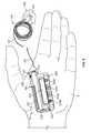
- the infusion pump system 10is shown in FIG. 6 as being held in a user's hand 5 so as to illustrate an exemplary size of the system 10 in accordance with some embodiments.
- This embodiment of the infusion pump system 10is compact so that the user can wear the system 10 (e.g., in the user's pocket, connected to a belt clip, adhered to the user's skin, or the like) without the need for carrying and operating a separate module.
- the cap device 130 of the pump device 100may be configured to mate with an infusion set 146 .
- the infusion set 146is tubing system that connects the infusion pump system 10 to the tissue or vasculature of the user (e.g., to deliver medicine into the tissue or vasculature under the user's skin)
- the infusion set 146may include a flexible tube 147 that extends from the pump device 100 to a subcutaneous cannula 149 retained by a skin adhesive patch 148 that secures the subcutaneous cannula 149 to the infusion site.
- the skin adhesive patch 148can retain the infusion cannula 149 in fluid communication with the tissue or vasculature of the patient so that the medicine dispensed through the tube 147 passes through the cannula 149 and into the user's body.
- the cap device 130may provide fluid communication between the output end 122 ( FIG. 1 ) of the medicine cartridge 120 and the tube 147 of the infusion set 146 .
- the tube 147may be directly connected to the output port 139 ( FIG. 1 ) of the cap device 130 .
- the infusion set 146may include a connector (e.g., a Leur connector or the like) attached to the tube 147 , and the connector can then mate with the cap device 130 to provide the fluid communication to the tube 147 .
- the usercan carry the portable infusion pump system 10 (e.g., in the user's pocket, connected to a belt clip, adhered to the user's skin, or the like) while the tube 147 extends to the location in which the skin is penetrated for infusion. If the user desires to monitor the operation of the pump device 100 or to adjust the settings of the infusion pump system 10 , the user can readily access the user interface 220 of the controller device 200 without the need for carrying and operating a separate module (refer for example to FIG. 6 ).
- the infusion pump system 10is pocket-sized so that the pump device 100 and controller device 200 can be worn in the user's pocket 6 or in another portion of the user's clothing.
- the pump device 100 and the controller device 200can be attached together and form the system that comfortably fits into a user's pocket 6 .
- the usercan carry the portable infusion pump system 10 and use the tube 147 of the infusion set 146 extends to direct the dispensed medicine to the desired infusion site.
- the usermay desire to wear the infusion pump system 10 in a more discrete manner. Accordingly, the user may pass the tube 147 from the pocket 6 , under the user's clothing, and to the infusion site where the adhesive patch 148 is positioned.
- the pump system 10can be used to delivery medicine to the tissues or vasculature of the user in a portable, concealable, and discrete manner.
- the infusion pump system 10may be configured to adhere to the user's skin 7 directly at the location in which the skin is penetrated for medicine infusion.
- a rear surface 102 ( FIG. 3 ) of the pump device 100may include a skin adhesive patch so that the pump device 100 is physically adhered to the skin of the user at a particular location.
- the cap device 130may have a configuration in which medicine passes directly from the cap device 130 into an infusion cannula 149 that is penetrated into the user's skin.
- the fluid output port 139 through the cap device 130can include a curve or a 90° corner so that the medicine flow path extends longitudinally out of the medicine cartridge and thereafter laterally toward the patient's skin 7 .
- the usercan readily access the user interface 220 of the controller device 200 without the need for carrying and operating a second, separate device.
- the usermay look toward the pump device 100 to view the user interface 220 of the controller device 200 that is removably attached thereto.
- the usercan temporarily detach the controller device 200 (while the pump device 100 remains adhered to the skin 7 ) so as to view and interact with the user interface 220 .
- the infusion pump system 10can be operated such that the pump device 100 is a disposable, non-reusable component while the controller device 200 is a reusable component.
- the pump device 100may be configured as a “one-time-use” device that is discarded after the medicine cartridge is emptied, expired, or otherwise exhausted.
- the pump device 100may be designed to have an expected operational life of about 1 day to about 30 days, about 1 day to about 20 days, about 1 to about 14 days, or about 1 day to about 7 days—depending on the volume of medicine in the cartridge 120 , the dispensation patterns that are selected for the individual user, and other factors.
- the medicine cartridge 120 containing insulinmay have an expected usage life about 7 days after the cartridge is removed from a refrigerated state and the septum 121 is punctured.
- the dispensation pattern selected by the usercan cause the insulin to be emptied from the medicine cartridge 120 before the 7-day period. If the insulin is not emptied from the medicine cartridge 120 after the 7-day period, the remaining insulin may become expired sometime thereafter. In either case, the pump device 100 and the medicine cartridge 120 therein can be discarded after exhaustion of the medicine cartridge 120 (e.g., after being emptied, expired, or otherwise not available for use).
- the controller device 200may be reused with subsequent new pump devices 100 ′ and new medicine cartridges 120 ′.
- the control circuitry, the user interface components, and other components that may have relatively higher manufacturing costscan be reused over a longer period of time.
- the controller device 200may be designed to have an expected operational life of about 1 year to about 7 years, about 2 years to about 6 years, or about 3 years to about 5 years—depending on a number of factors including the usage conditions for the individual user. Accordingly, the user is permitted to reuse the controller device 200 (which may include complex or valuable electronics) while disposing of the relatively low-cost pump device 100 after each use.
- Such a pump system 10can provide enhanced user safety as a new pump device 100 ′ (and drive system therein) is employed with each new fluid cartridge 120 .
- the pump device 100can be readily removed from the controller device 200 when the medicine cartridge 120 is exhausted.
- the medicine cartridge 120is inserted into the cavity 116 ( FIG. 1 ) of the pump housing 110 where it is retained by the cap device 130 .
- a portion of the pump housing 110can comprise a transparent or translucent material so that at least a portion of the medicine cartridge 120 is viewable therethrough.
- the usermay want to visually inspect the medicine cartridge when the plunger 125 is approaching the output end 122 of the medicine cartridge, thereby providing a visual indication that the medicine cartridge may be emptied in the near future.
- the barrel 111 of the pump housing 110comprises a generally transparent polymer material so that the user can view the medicine cartridge 120 to determine if the plunger 125 is nearing the end of its travel length.
- some embodiments of the pump device 100may include a label 117 a that is adhered around the barrel 111 .
- the label 117 amay provide a convenient location for basic user instructions, product identification information, and other information related to the infusion pump system 10 .
- the label 117 amay include a window 117 b through which the user may visually inspect if the plunger 125 is nearing the end of its travel length.
- the pump device 100has been used to a point at which the medicine cartridge 120 is exhausted.
- the plunger 125has been advanced, toward the left in FIG. 9 , over a period of time so that all or most of the medicine has been dispensed from the cartridge 120 .
- the controller device 200may provide a visual or audible alert when this occurs so as to remind the user that a new medicine cartridge is needed.
- the usermay visually inspect the medicine cartridge 120 through the barrel 111 of the pump housing 110 (and through the window 117 b of the label 117 a in this embodiment) to determine if the medicine cartridge 120 is almost empty.
- the pump device 100can be readily separated from the controller device 200 by actuating the release member 215 .
- the release member 215is a latch on the controller device 200 that is biased toward a locking position to engage the pump device 100 .
- the latchmay be arranged to engage one or more features on a lateral side of the pump housing 110 .
- the usermay actuate the release member 215 by moving the release member 215 in a lateral direction 216 ( FIG. 9 ) away from the pump device 100 (e.g., by applying a force with the user's finger).
- the segmented guide rail 114 a - bis free to slide longitudinally in the guide channel 214 a - b without interference from the release member 215 . Accordingly, the user can move the pump device 100 in a longitudinal direction 217 away from the controller device 200 .
- the segmented guide rail 114 a - bmay slide along the guide channel 214 a - b , the extension 113 ( FIG. 1 ) may be withdrawn from the mating depression 213 ( FIG. 10 ), and the electrical connector 118 can be separated from the mating connector 218 .
- the pump device 100is physically and electrically disconnected from the controller device 200 while the pump device retains the exhausted medicine cartridge 120 .
- the gasket 140 compressed between the pump device 100 and the controller device 200may comprise a resilient material.
- the gasket 140can provide a spring-action that urges the pump device 100 to shift a small amount away from the controller device 200 when the release member 215 is moved to the unlocked position (e.g., move in the lateral direction 216 in the embodiment shown in FIG. 9 ).
- the pump device 100can automatically and sharply move a small distance (e.g., about 0.5 mm to about 5 mm) away from the controller 200 when the release member 215 is moved to the unlocked position.
- a small distancee.g., about 0.5 mm to about 5 mm
- Such an automatic separationprovides a convenient start for the user to detach the pump device 100 away from the controller device 200 .
- this automatic separation caused by the spring-action of the gasket 140can provide a swift disconnect between the electrical connectors 118 and 218 when the pump device 100 is being replaced.
- the same controller device 200can be reused with a new pump device 100 ′ having a new medicine cartridge 120 ′ retained therein, and the previously used pump device 100 can be discarded with the exhausted medicine cartridge 120 .
- the new pump device 100 ′( FIG. 11 ) can have a similar appearance, form factor, and operation as the previously used pump device 100 (FIGS. 9 , 10 and 12 ), and thus the new pump device 100 ′ can be readily attached to the controller device 200 for controlled dispensation of medicine from the new medicine cartridge 120 ′.
- the usermay prepare the new pump device 100 for use with the controller device 200 .
- the usermay insert the new medicine cartridge 120 ′ in the cavity 116 of the new pump device 100 ′ and then join the cap device 130 to the pump housing to retain the new medicine cartridge 120 ′ therein (refer, for example, to FIG. 1 ).
- the tubing 147 of the infusion set 146is not shown in FIG. 11 , it should be understood that the tubing 147 may be attached to the cap device 130 prior to the cap device 130 being joined with the housing 110 .
- a new infusion set 146can be connected to the cap device 130 so that the tubing 147 can be primed (e.g., a selected function of the pump device 100 controlled by the controller 200 ) before attaching the infusion set patch to the user's skin.
- the new medicine cartridge 120 ′may be filled with medicine such that the plunger 125 is not viewable through the barrel 111 .
- the pump device 100may be configured as a disposable “one-time-use” device that is discarded by the user after the medicine cartridge 120 is emptied, is expired, has ended its useful life, or is otherwise exhausted.
- the pump device 100may be discarded into a bin 20 , which may include a trash bin or a bin specifically designated for discarded medical products.
- the useris permitted to dispose of the relatively low-cost pump device 100 after each use while reusing the controller device 200 (which may include complex or valuable electronics) with subsequent new pumps 100 ′.
- the infusion set 146(not shown in FIG. 12 , refer to FIG. 6 ) that was used with the pump device 100 may be removed from the user and discarded into the bin 20 along with the pump device 100 .
- the infusion set 146can be disconnected from the previous pump device 100 and attached to the new pump device 100 ′.
- the usermay detach the infusion set cannula and patch from the skin so as to “re-prime” the tubing with medicine from the new pump device 100 ′ to remove air pockets from the tubing. Thereafter, the infusion set cannula and patch can be again secured to the user's skin.
- the new pump device 100 ′can be removably attached to the controller device 200 to assemble into the infusion pump system 10 for delivery of medicine to the user.
- the usermay prepare the new pump device 100 ′ for use by pulling the removable tab 141 away from the pump housing 110 .
- the new pump device 100 ′includes the removable tab 141 to seal the battery in the unused pump device 100 ′ and thereby maintain the battery in a storage mode (refer, for example, to FIG. 12 in which the removable tab 141 is arranged to cover an internal face of the vent 115 ).
- the removable tab 141can be pulled away from the pump housing 110 (and away from the battery therein), which switches the battery into an activation mode.
- the shelf-life of the pump device 100 ′(prior to usage with the controller device 200 ) may be extended by sealing the battery in a storage mode because little, if any, energy is dissipated from the battery when in the storage mode.
- the pump device 100 ′can be connected to the controller device 200 by advancing the pump device 100 ′ in a longitudinal direction 219 ( FIG. 13 ) toward the controller device 200 .
- the movementis guided by the slider channel 112 ( FIGS. 4-5 ) and the segmented rails 114 a - b .
- the slider channel 112 of the pump housingengages the rail 212 of the controller housing 210 .
- the front portion of the segmented rail 114 aslides into the rear portion of the guide channel 214 b .
- the front portion of the segmented rail 114 aincludes a ramp surface 114 c (refer also to FIG.
- the release member 215is temporarily forced away from the guide channel 214 a - b so that the front portion of the segmented rail 114 a passes over the release member 215 , which enables the electrical connector 118 of the pump device 100 ′ to engage with the mating connector 218 of the controller device 200 .
- the release member 215biased to return to its latched position and is shifted to a position in the guide channel 214 a - b between the segmented rails 114 a - b so as to prevent withdrawal of the pump device 100 ′.
- the extension 113 ( FIG. 1 ) and barrel 111are mated with the corresponding depression 213 and barrel channel 211 so as to resist relative rotational movement between the pump device 100 and the controller device 200 .
- the physical attachment of electrical connectors 118 and 218may also serve to resist relative rotational movement between the pump device 100 and the controller device 200 .
- the slide channel 112is mated with the corresponding rail 112 ( FIG. 1 ) and barrel channel 211 so as to resist relative side-to-side movement between the pump device 100 and the controller device 200 .
- the guided motion in the longitudinal direction 219provides the user with a convenient “one-movement” process to attach the pump device 100 ′ and the controller device 200 .
- the usercan readily slide the pump device 100 ′ and the controller device 200 toward one another in a single movement (e.g., in the longitudinal direction) that causes both a physical connection and an electrical connection.
- the infusion pump system 10permits users to readily join the pump device 100 ′ and the controller device 200 without compound or otherwise difficult hand movements—a feature that can be beneficial to child users or to elderly users.
- the gasket 140is compressed between the opposing surfaces of the pump housing 110 and the controller housing 210 .
- Such a configurationprovides a water-resistance seal around the electrical connection that protects the sensitive internal components of the pump device 100 ′ and the controller device 200 from damage or malfunction.
- the tubing 147 of the infusion set 146is not shown in FIGS. 13-14 , it should be understood that the tubing 147 may be attached to the cap device 130 to provide a fluid path from the new pump device 100 ′ to the user.
- the pump device 100 ′can removably attach to the controller device 200 in a manner that provides a secure fitting, an overall compact size, and a reliable electrical connection.
- the controller device 200can be electrically connected with the pump device 100 ′ while the controller device 200 remains outside of the pump housing 110 (and, likewise, the pump device 100 remains outside of the controller housing 210 ).
- the overall size of the system 10can be minimized, thereby providing an infusion pump system having a discrete size and enhanced portability.
- the controller device 200houses a number of components that can be reused with a series of successive pump devices 100 .
- the controller device 200includes control circuitry 240 arranged in the controller housing 210 that is configured to communicate control signals to the drive system of the pump device 100 .
- the control circuitry 240includes a main processor board 242 that is in communication with a power supply board 244 .
- the control circuitry 240includes at least one processor 243 that coordinates the electrical communication to and from the controller device 200 (e.g., communication between the controller device 200 and the pump device 100 ).
- the processor 243can be arranged on the main processor board 242 along with a number of other electrical components such as memory devices.
- the control circuitry 240can be programmable in that the user may provide one or more instructions to adjust a number of settings for the operation of the system 10 . Such settings may be stored in the memory devices arranged in the control circuitry 240 . Furthermore, the control circuitry 240 may include one or more dedicated memory devices that store executable software instructions for the processor 243 . The control circuitry 240 may include other components, such as sensors, that are electrically connected to the main processor board 242 . For example, at least a portion of the occlusion sensor 250 (not shown in FIG. 15 ) can be electrically connected to the main processor board 242 via a flexible circuit substrate or one or more wires.
- the user interface 220 of the controller device 200can include input components, output components, or both that are electrically connected to the control circuitry 240 .
- the user interface 220includes a display device 222 having an active area that outputs information to a user and four buttons 224 a - d that receive input from the user.
- the display 222may be used to communicate a number of settings or menu options for the system 10 .
- control circuitry 240may receive the input commands from the user's button selections and thereby cause the display device 222 to output a number of menus or program screens that show particular settings and data (e.g., review data that shows the medicine dispensing rate, the total amount of medicine dispensed in a given time period, the amount of medicine scheduled to be dispensed at a particular time or date, the approximate amount of medicine remaining the cartridge 120 , or the like).
- the controller circuit 240can be programmable in that the input commands from the button selections can cause the controller circuit 240 to change any one of a number of settings for the infusion pump system 100 .
- control circuitry 240may include a cable connector (e.g., a USB connection port or another data cable port) that is accessible on an external portion of the controller housing 210 .
- a cablemay be connected to the control circuitry 240 to upload data or program settings to the controller circuit or to download data from the control circuitry 240 .
- datacan be downloaded from the control circuitry 240 (via the cable connector) to a computer system of a physician or a user for purposes of analysis and program adjustments.
- the data cablemay also provide recharging power.
- the control circuitry 240 of the controller device 200may include a second power source 245 that can receive electrical energy from a first power source 345 ( FIG. 17 ) housed in the pump device 100 .
- the second power source 245is coupled to the power supply board 244 of the control circuitry 240 .
- the hard-wired transmission of the electrical energycan occur through the previously described connectors 118 and 218 ( FIGS. 4-5 ).
- the first power source 345FIG. 17
- the first power source 345may include a high density battery that is capable of providing a relatively large amount of electrical energy for its package size, while the second power source 245 ( FIG.
- the first battery 345 ( FIG. 17 ) disposed in the pump device 100can be used to deliver electrical energy over time (e.g., “trickle charge”) to the second battery 245 when the controller device 200 is removably attached to the pump device 100 .
- the first battery 345 ( FIG. 17 )may comprise a zinc-air cell battery.
- the zinc-air cell batterymay have a large volumetric energy density compared to some other battery types.
- the zinc-air cell batterymay have a volumetric energy density of greater than about 900 Watt-hours/Liter (Wh/L), about 1000 Wh/L to about 1700 Wh/L, and about 1200 Wh/L to about 1600 Wh/L.
- the zinc-air cell batterymay have a long storage life, especially in those embodiments in which the battery is sealed (e.g., by the removable tab 141 or the like) during storage and before activation.
- One exemplary zinc-air cell batteryprovides a potential voltage of about 1.1V to about 1.6V (about 1.2V to about 1.4 V, and about 1.3 V in one embodiment), a current output of about 8 mA to about 12 mA (about 10 mA in one embodiment), and a storage capacity of greater than about 600 mA•h (about 650 mA•h in one embodiment).
- the second battery 245may include a high current-output device that is housed inside the controller housing 210 .
- the second battery 245can be charged over a period of time by the first battery 345 ( FIG. 17 ) and then intermittently deliver high-current bursts to the drive system 300 over a brief moment of time.
- the second battery 245may comprise a lithium-polymer battery.
- the lithium polymer battery disposed in the controller device 200may have an initial current output that is greater than the zinc-air cell battery disposed in the pump device 100 , but zinc-air cell battery may have an energy density that is greater than the lithium polymer battery (e.g., the lithium polymer battery disposed in the controller device 200 may have a volumetric energy density of less than about 600 Wh/L).
- the lithium-polymer battery 245is readily rechargeable, which permits the zinc-air battery disposed in the pump device 100 to provide electrical energy to the lithium-polymer battery 245 for purposes of recharging.
- One exemplary lithium-polymer batteryprovides a initial current output of about greater than 80 mA (about 90 mA to about 110 mA, and about 100 mA in one embodiment) and a maximum potential voltage of about 4.0V to and 4.4V (about 4.2 V in one embodiment).
- the second power source 245may comprise a capacitor device capable of being recharged over time and intermittently discharging a current burst to activate the drive system 300 .
- the infusion pump system 10having two power sources 245 , 345 , one arranged in the pump device 100 and another arranged in the reusable controller device 200 , permits a user to continually operate the controller device 200 without having to recharge a battery via a wall-plug or other cable.
- the controller device 200can be reusable with a number of pump devices 100 (e.g., attach the new pump device 100 ′ after the previous pump device 100 is expended and disposed)
- the second power source 245 in the controller device 200can be recharged over a period of time each time a new pump device 100 is connected thereto.
- Such a configurationcan be advantageous in those embodiments in which the pump device 100 is configured to be a disposable, one-time-use device that attaches to a reusable controller device 200 .
- the “disposable” pump devices 100recharge the second power source 245 in the “reusable” controller device 200 , thereby reducing or possibly eliminating the need for separate recharging of the controller device 200 via a power cord plugged into a wall outlet.
- the control circuitry 240includes an external reference system 230 having a receiver 232 and an external reference circuitry 234 .
- the receiver 232communicates with the external reference circuitry 234 and receives a signal indicative of a time, a date, or both from a remote time and date reference source 235 (or 236 ).
- the remote time and date reference source 235may include a radio transmitter, a satellite, a cellular telephone tower, or other signal broadcasting source.
- the remote reference source 235(or 236 ) broadcasts a reference signal that may be contemporaneously broadcasted or otherwise transmitted to multiple devices including, but not limited to, the portable medical devices, such as the infusion pump system 10 , described herein.
- the broadcast signalis not necessarily transmitted exclusively to a targeted device, but can be transmitted over a broad geographical area and can be received by more than one device (e.g., the infusion pump system 10 , other medical devices, cell phones, GPS monitor devices, radio devices, and others).
- the receiver 232is illustrated as extending to a region along the controller housing 210 . In alternative embodiments, the receiver 232 can be fully housed within the controller housing 210 .
- the receiver 232In response to receiving the broadcast signal indicative of the time/date from the remote time and date reference source 235 (or 236 ), the receiver 232 sends a corresponding signal to the external reference circuitry 234 .
- the external reference circuitry 234processes the signal and sends a time/date update signal to the processor 243 of the control circuitry 240 , which regulates operation of the infusion pump system 10 based thereon.
- the processor 243can include an internal reference circuitry, which is automatically updated based on the time/date update signal.
- This automatic updatemay occur at predetermined events.
- the automatic updatemay occur upon replacement of a battery, at regularly scheduled intervals (e.g., every 5, 10, 15, 30 minutes, every hour, every few hours, twice daily, once daily, as a few examples).
- the automatic updatemay occur continuously.
- the external reference system 230enables the infusion pump system 10 ( FIG. 1 ) to have an internally stored reference time that is updated by an external time signal.
- the external time signalmay include a broadcast signal generated by a radio clock transmitter, a cellular telephone system and/or a global positioning system (GPS).
- GPSglobal positioning system
- the pump system 10may provide the basal delivery of medicine at the correct times according to the predetermined delivery schedule.
- the systemmay include computer-readable memory in the controller device 200 that can record dispensation data and other data along with accurate time-stamps that are based on the updated time and date information. Accordingly, some medical decisions, which are based on a review of pumping details, can be made with confidence knowing that the time and date information was accurate when it was recorded.
- some embodiments of the external reference system 230may be provided as a radio clock system, which is synchronized by a time code bit stream that is transmitted by a radio transmitter 236 .
- the radio transmitter 236can be coupled to a time standard, such as an atomic clock, so that the radio transmitter broadcasts a time/date signal indicative of the time standard.
- the receiver 232includes an antenna that receives a radio frequency (RF) time code signal
- the external reference circuitry 234includes a receiving circuit, which converts the RF time/date code signal into a digital time/date code signal.
- the external reference circuitry 234 or another component of the control circuitry 240can decode the digital code signal and outputs a time/date signal.
- the remote time and date reference sourcecan include one or more of the following:
- the external reference system 230may be configured to receive a GPS clock signal that is transmitted from a GPS satellite 235 or other satellite.
- the GPS clock systemcombines time estimates from multiple satellite atomic clocks with error estimates maintained by a network or ground stations. Because GPS clocks simultaneously compute the time and position from several sources, they can automatically compensate for line-of-sight delay and many radio propagation defects. Furthermore, GPS clocks may achieve sub-microsecond precision under ideal conditions. The GPS clock provides sufficient accuracy in that the displayed time will be accurate to approximately one half of a second, which can be adequate for medical device purposes.
- the GPS clock systemmay operate with one or more of a GPS satellite, a Galileo satellite and a GLONASS (Global Navigation Satellite System). These satellite navigation systems have a caesium or rubidium atomic clock on each satellite, reference to a clock or clocks on the Earth. Some navigation units can serve as local time standards, with a precision of about one microsecond (IS).
- ISmicrosecond
- the external reference source 235may include a cellular telephone time signal (e.g., from one or more cellular towers, from a cellular base station, or from a cellular satellite).
- a CDMA (code division multiple access) clockmay be implemented, which include high quality standard time signals.
- the externals reference source 235can include a computer, such as a desktop computer or a laptop computer.
- the pump device 100can be coupled to the computer to electronically communicate with the computer. This can be achieved using a wired connection or a wireless connection, such as a Bluetooth connection, between the pump device 100 and the computer.
- the external time referencecan be provided using the network time protocol (NTP) of a network, of which the computer is a part. NTP functions to synchronize the clocks of computers over a network By coupling the pump device 100 to the computer, the pump device 100 can function as an extension of the network and the time reference of the pump device 100 can by synchronized like that of other components of the network. It is also anticipated that the pump device 100 can directly communicate with an NTP server or a National Institute of Standards and Technology (NIST) server, either of which can provide the external time reference.
- NTPNational Institute of Standards and Technology
- the external reference system 230may provide a number of advantages when implemented in a medical device, such as the previously described pump system 10 .
- the external reference system 230can be used to maintain accurate time and date information even in the event of a power interruption.
- the internal reference timecan be affected.
- the external reference system 230can communicate with the remote time and date reference source 235 , 236 to accurately update the internal reference time and date.
- the external reference system 230can reduce the risk of the reference time either not being updated or not being accurately updated by the user.
- the accuracy of the internal reference timecan be maintained throughout the operation of the medical device.
- the medical deviceincludes an insulin pump system, such as the portable infusion pump system 10 described in connection with FIGS. 1-3 .
- the insulin pump system 10can provide time-based dosing of basal insulin.
- the basal dosing ratemay be adjusted by the controller device 200 based on the particular time of day.
- the dosing ratecan be set at one level early in the morning, when the user is first awakening.
- the controller device 200may automatically adjust the dosing rate to a different level at mealtimes or in the evening, for example.
- the external reference system 230provides an accurate time setting to ensure that the dosing rate is appropriate for the time of day.
- a usermay suspend or otherwise take a break from treatment, which may lead the user to remove the power supply from the medical device (e.g., to render alarms inactive).
- the internal reference timemay become inaccurate when the medical device is reactivated.
- the external reference system 230can resolve this inaccuracy by enabling the internal reference time to be automatically updated based on the external reference signal from the remote time and date reference source 235 , 236 .
- the use of the medical devicecan be simplified, because the user is not required to manually set the time and date.
- the documentationsuch as an instruction manual, which accompanies the medical device, may be simplified. For example, instructions on how to manually set the time and date may not be required.
- the external reference system 230can also be implemented to automatically adjust the dosing schedule in the case of a time change.
- the local time of a particular locationmay increase or decrease to account for daylight savings time.
- a usermay travel between time zones, where the time change can be several hours or even an entire day.
- the external reference system 230can alert the user to such time changes and assist the user in adapting the dosing schedule to the new time zone.
- the time zone changemay be for a brief time period, such as when a user travels out of his/her home time zone for a brief period and then returns. In such a case, the user may instruct the insulin pump system 10 to function as normal, without adjusting the dosing rate to the new time zone.
- an adaptive time-shift learning featurecan be provided.
- the usercan indicate to the insulin pump system 10 (e.g., via a button on the controller device 200 ), as to when the first dosing should occur. For example, when the user awakens in the morning after a time change has occurred, the user can press a button or other input to instruct the initial dosing to occur at that time. In this manner, the dosing schedule can automatically adjust based on the timing of the initial dosing.
- the usercan indicate to the insulin pump system 10 , as to when a mealtime (e.g., the first mealtime) is to occur after a time change.
- a mealtimee.g., the first mealtime
- the usermay press a button or other input to alert the insulin pump system 10 .
- the dosing schedulemay automatically adjust based on the timing of a meal.
- the dosing ratemay be gradually adjusted based on the time change. More specifically, the dosing schedule, which is controlled by the controller device 200 , may be incrementally shifted to adjust to the time change. For example, the dosing schedule may be shifted X minutes per hour until the dosing schedule corresponds with the new time.
- the value Xcan increase or decrease based on the time change. For example, the value X may be lower for a small time change than that for a larger time change. In one embodiment, the value X may be limited to avoid an overly aggressive shift.
- the value Xcan be a function of the rate at which the user's internal time reference changes. More specifically, the hypothalamus gland of the user regulates certain metabolic processes and other autonomic activities. The hypothalamus also coordinates seasonal and circadian rhythms. A circadian rhythm is a roughly 24-hour cycle in the physiological processes of living beings. The value X can relate to the circadian rhythm of the user.
- the dosing schedulemay adjust to conform to the new time zone by making a step-shift. For example, if the user travels to a time zone that is one hour ahead/behind of the user's home time zone, the dosing schedule may step-shift one hour forward/backward, upon request of the user. The amount of the step-shift may be limited to avoid occurrences of too much or too little dosing. For example, if the step-shift would result in over- or under-dosing, the user is alerted and the step-shift in the dosing schedule does not occur.
- the usercan anticipate a tome change and can initiate a dosing schedule adaptation prior to the time change. For example, the user may be preparing for a trip to a different time zone and can initiate a change in the dosing schedule prior to departing on the trip. In this manner, the effect of a time zone change can be better managed and minimized.
- a flowchartillustrates an exemplary adaptive time-shift learning process 1600 .
- the controller device 200updates the date and/or time based on the external reference signal transmitted from the external reference source 235 , 236 to the receiver 232 .
- the controller device 200determines whether there is a significant time change. For example, a significant time change occurs when the time is shifted by at least a threshold amount (e.g., greater than about 15 minutes, greater than about 30 minutes, and about 1 hour).
- exemplary significant time changesinclude, but are not limited to, a time change due to daylight savings time and/or a time change due to a transition between time zones.
- the external reference system 230can automatically adjust the internal reference time of the controller device 200 without any further user input, and the process 1600 can loop back to step 1602 . If there is a significant time change, the exemplary adaptive time-shift learning determines the amount of the time change at step 1606 .
- the controller device 200alerts the patient as to the time change.
- the controller device 200adjusts the dosing schedule based on a user input at step 1616 . More specifically, the dosing schedule may be adjusted based on the user indicating an initial dosing for the day and/or the user indicating a mealtime (e.g., breakfast, lunch and/or dinner), as described in further detail above.
- a mealtimee.g., breakfast, lunch and/or dinner
- the controller device 200determines whether a gradual adjustment is to be made. If a gradual adjustment is to be made, the controller device 200 adjusts the dosing schedule based on the above-described rate (i.e., X value) at step 1618 . If a gradual dosing schedule adjustment is not to be made, the controller device 200 conforms the dosing schedule to the new time. For example, the dosing schedule may step-shift forward or backward based on the new time. Such a step-shift may be limited, however, based on several factors including, but not limited to, the current dosing rate, the dosing rate after the step-shift, a recent dosing history and the like. In this manner, it may be insured that the user does not receive too much or too little insulin, for example, as a result of the step-shift.
- the infusion pump systemincludes the pump device 100 having a drive system 300 controlled by the removable controller device 200 ( FIGS. 1-2 ). Accordingly, the drive system 300 can accurately and incrementally dispense fluid from the pump device 100 in a controlled manner.
- the drive system 300may include a flexible piston rod 370 that is incrementally advanced toward the medicine cartridge 120 so as to dispense the medicine from the pump device 100 .
- At least a portion of the drive system 300is mounted, in this embodiment, to the pump housing 110 .
- the pump housing 110includes a chassis 107 , a shell portion 108 , and a cover mount 109 .
- the shell portion 108can be used to cover at least a portion of the drive system 300 .
- the shell 108may include an inner curved surface against which a curved section of a piston rod 370 rests.
- the cover mount 109may be assembled to the chassis 107 of the pump housing 110 to secure some components of the drive system 300 in position between the cover mount 109 and the chassis 107 .
- the “unused” or retracted portion of the piston rod 370may rest in a channel defined in the top of the cover mount 109 .
- the shell portion 108can slide over the cover mount 109 and join with the chassis 107 to form the assembled pump housing 110 .
- the drive system 300may include a battery powered actuator (e.g., reversible motor 320 or the like) that drives a gear system 330 to actuate a ratchet-spring mechanism and advance the flexible piston rod 370 toward the medicine cartridge 120 (as described in commonly assigned U.S. patent application Ser. No. 11/677,706 filed on Feb. 22, 2007, which is incorporated herein by reference). Accordingly, control signals from the controller device 200 can be transmitted via the electrical connector 118 so as to control the motor 320 , which causes the gear system 330 and other components to actuate and thereby advance the piston rod 370 an incremental distance toward the medicine cartridge. This incremental motion urges the plunger 125 ( FIG.
- the drive system 300 of the pump device 100causes medicine to incrementally dispense from the medicine cartridge 120 and into the targeted user.
- the external reference systemcan be arranged in medical devices other that the wearable infusion pump system 10 .
- medical devices for the treatment of diabetesthat are carried or otherwise worn by the user can incorporate an external reference system configured to receive an external signal from a remote time and date reference source (e.g., a radio transmitter, a satellite, another broadcast source or the like).
- a remote time and date reference sourcee.g., a radio transmitter, a satellite, another broadcast source or the like.
- these diabetes treatment devicese.g., infusion pumps, glucose meters, continuous glucose monitors, and the like
- a continuous glucose monitoring system 600can be incorporate an external reference system 630 that includes a receiver 632 and external reference circuitry 634 . These instruments 632 and 634 can be used to receive and decode the external reference signal that is broadcast from a remote time and date reference source 635 (e.g., a satellite, a radio transmitter, a cellular system, or another broadcast source). Similar to the previously described infusion pump system 10 , the continuous glucose monitoring system 600 is configured to receive an external signal from the remote time and date reference source 635 to provide automatic time-setting capabilities and related maintenance features.
- a remote time and date reference source 635e.g., a satellite, a radio transmitter, a cellular system, or another broadcast source.
- the continuous glucose monitoring system 600includes a body-worn glucose sensor device 610 that wirelessly communicates with a portable controller device 620 .
- the glucose sensor device 610may comprise a sensor shaft 619 that penetrates under the skin (e.g., into the subcutaneous layer) while the sensor housing is adhered to the skin.
- the sensor housingmay contain a power source and a communication device 615 that permits the sensor data to be wirelessly transmitted to the controller device 620 .
- the controller device 620can include a display 622 to communicate the sensed glucose level and one or more buttons 624 for user interaction.
- the controller device 620can include one or more memory devices that stored a log of the sensed glucose readings and the time and date that each reading was detected. As such, the user or a medical practitioner can perform a retrospective analysis of the user's blood glucose readings to determine if modifications should be made to the user's food consumption, physical activity, and insulin dosages.
- the controller device 200includes the external reference system 630 that includes the receiver 632 and the external reference circuitry 634 .
- the receiver 632receives a signal indicative of a time, a date, or both from the remote time and date reference source 635 .
- the receiver 632sends a corresponding signal to the external reference circuitry 634 .
- the external reference circuitry 634processes the signal and sends a time/date update signal to the control circuitry of the device 620 .
- the controller device 620can include an internal reference circuitry, which is automatically updated based on the new time/date data from the external reference circuitry 634 . This automatic update may occur at predetermined events.
- the automatic updatemay occur upon replacement of a battery, at regularly scheduled intervals (e.g., every 5, 10, 15, 30 minutes, every hour, every few hours, twice daily, once daily, as a few examples). In alternative embodiments, the automatic update may occur continuously.
- the external reference system 630enables the continuous glucose monitoring system 600 to have an internally stored reference time that is updated by an external time signal.
- the external time signalmay include a broadcast signal generated by a radio clock transmitter, a cellular telephone system and/or a global positioning system (GPS).
- GPSglobal positioning system
- an accurate reference time for the continuous glucose monitoring system 600can be maintained.
- This accurate reference timefor example, enables the continuous glucose monitoring system 600 to include an accurate time-stamp for each of the glucose readings that are stored in the previously described log.
- the sensor data that is collected and stored within the memory of the controller device 620can include an associated time-stamp, the subsequent analysis of the recorded data is enhanced due to the high accuracy of the time-stamp. Accordingly, some medical decisions, which are based on a review of pumping details, can be made with confidence knowing that the time and date information was accurate when it was recorded.
- the external reference systemcan be arranged other medical devices for the treatment of diabetes.
- a blood glucose meter devicecan incorporate an external reference system configured to receive an external signal from a remote time and date reference source (e.g., a radio transmitter, a satellite, another broadcast source or the like).
- a remote time and date reference sourcee.g., a radio transmitter, a satellite, another broadcast source or the like.
- Such a glucose meter devicecan be carried by a diabetic user so that the user may periodically provide a blood sample on a test strip and then insert the test blood strip into the meter device for a periodic glucose reading.
- the glucose meter devicecan include a mechanism for piercing a user's skin to allow a limited amount of blood to pass to the surface of the skin (e.g., a blood drop for the test strip).
- the usercan apply the blood as a blood sample to a test blood strip.
- An end of the test blood strip, which includes the applied blood sample,can be inserted into a strip receiver of the glucose meter device.
- the glucose meter devicecan test the blood sample to determine the user's current blood glucose level.
- the determined blood glucose levelcan be provided to the user visually (e.g., using a display) and/or audibly (e.g., using a speaker).
- the glucose meter devicecan be configured to store the glucose readings in a log (e.g., stored in one or more memory devices of the glucose meter control circuitry). These stored reading may be associated with a time stamp that indicates the time and date of the blood glucose reading.
- the glucose meter devicecan be equipped with the external reference system (as previously described) to receive a reference time and date signal and thereafter update the internal time and date settings in the control circuitry.
- Such an automated time updating featurecan ensure that the log's time-stamp for each glucose reading is accurate, which can be beneficial to a physician or user who is performing a retrospective analysis of the user's blood glucose level throughout portions of the day or week.
- a number of diabetes treatment devicese.g., infusion pumps, glucose meters, continuous glucose monitors, and the like
Landscapes
- Health & Medical Sciences (AREA)
- Engineering & Computer Science (AREA)
- Biomedical Technology (AREA)
- Public Health (AREA)
- General Health & Medical Sciences (AREA)
- Veterinary Medicine (AREA)
- Animal Behavior & Ethology (AREA)
- Heart & Thoracic Surgery (AREA)
- Life Sciences & Earth Sciences (AREA)
- Hematology (AREA)
- Vascular Medicine (AREA)
- Anesthesiology (AREA)
- General Business, Economics & Management (AREA)
- Business, Economics & Management (AREA)
- Epidemiology (AREA)
- Primary Health Care (AREA)
- Medical Informatics (AREA)
- Fluid Mechanics (AREA)
- Physics & Mathematics (AREA)
- Chemical & Material Sciences (AREA)
- Bioinformatics & Cheminformatics (AREA)
- Medicinal Chemistry (AREA)
- Infusion, Injection, And Reservoir Apparatuses (AREA)
Abstract
Description
- U.S. NIST (National Institute of Standards and Technology) broadcasts
- U.S. Longwave radio station WWVB at 60 kHz and 50 kW
- U.S. Shortwave radio station WWV at 2.5, 5, 10, 15 and 20 MHz and 2.5-10 kW
- U.S. Shortwave radio station WWVH at 2.5, 5, 10 and 15 MHz and 2.5-10 kW
- German broadcasts from DCF77 (Mainflingen) at 77.5 kHz
- Canadian broadcasts from CHU (Ottawa) at 3.33, 7.335 and 14.67 MHz
- UK broadcasts from MSF (an atomic clock near Rugby) at 60 kHz
- Japanese broadcasts from BY radio stations at 40/60 kHz
- Chinese broadcasts from the BPM radio station (Xi'an) at 2.5, 5, 10 and 15 MHz
- Swiss Broadcasts from the HBG longwave transmitter (Prangins) at 75 kHz
- French broadcasts from radio station TDF (Allouis) at 162 kHz
Claims (49)
Priority Applications (4)
| Application Number | Priority Date | Filing Date | Title |
|---|---|---|---|
| US13/344,836US8870853B2 (en) | 2007-09-06 | 2012-01-06 | Operating a portable medical device |
| US14/504,899US10226572B2 (en) | 2007-09-06 | 2014-10-02 | Operating a portable medical device |
| US16/256,055US11000645B2 (en) | 2007-09-06 | 2019-01-24 | Operating a portable medical device |
| US17/307,613US12403245B2 (en) | 2007-09-06 | 2021-05-04 | Operating a portable medical device |
Applications Claiming Priority (3)
| Application Number | Priority Date | Filing Date | Title |
|---|---|---|---|
| US11/851,194US7717903B2 (en) | 2007-09-06 | 2007-09-06 | Operating an infusion pump system |
| US12/781,450US8109921B2 (en) | 2007-09-06 | 2010-05-17 | Operating a portable medical device |
| US13/344,836US8870853B2 (en) | 2007-09-06 | 2012-01-06 | Operating a portable medical device |
Related Parent Applications (1)
| Application Number | Title | Priority Date | Filing Date |
|---|---|---|---|
| US12/781,450ContinuationUS8109921B2 (en) | 2007-09-06 | 2010-05-17 | Operating a portable medical device |
Related Child Applications (1)
| Application Number | Title | Priority Date | Filing Date |
|---|---|---|---|
| US14/504,899DivisionUS10226572B2 (en) | 2007-09-06 | 2014-10-02 | Operating a portable medical device |
Publications (2)
| Publication Number | Publication Date |
|---|---|
| US20120109100A1 US20120109100A1 (en) | 2012-05-03 |
| US8870853B2true US8870853B2 (en) | 2014-10-28 |
Family
ID=39772959
Family Applications (6)
| Application Number | Title | Priority Date | Filing Date |
|---|---|---|---|
| US11/851,194Active2028-05-05US7717903B2 (en) | 2007-09-06 | 2007-09-06 | Operating an infusion pump system |
| US12/781,450Active2027-09-17US8109921B2 (en) | 2007-09-06 | 2010-05-17 | Operating a portable medical device |
| US13/344,836Active2028-02-21US8870853B2 (en) | 2007-09-06 | 2012-01-06 | Operating a portable medical device |
| US14/504,899Active2028-03-15US10226572B2 (en) | 2007-09-06 | 2014-10-02 | Operating a portable medical device |
| US16/256,055Active2027-10-18US11000645B2 (en) | 2007-09-06 | 2019-01-24 | Operating a portable medical device |
| US17/307,613Active2027-12-31US12403245B2 (en) | 2007-09-06 | 2021-05-04 | Operating a portable medical device |
Family Applications Before (2)
| Application Number | Title | Priority Date | Filing Date |
|---|---|---|---|
| US11/851,194Active2028-05-05US7717903B2 (en) | 2007-09-06 | 2007-09-06 | Operating an infusion pump system |
| US12/781,450Active2027-09-17US8109921B2 (en) | 2007-09-06 | 2010-05-17 | Operating a portable medical device |
Family Applications After (3)
| Application Number | Title | Priority Date | Filing Date |
|---|---|---|---|
| US14/504,899Active2028-03-15US10226572B2 (en) | 2007-09-06 | 2014-10-02 | Operating a portable medical device |
| US16/256,055Active2027-10-18US11000645B2 (en) | 2007-09-06 | 2019-01-24 | Operating a portable medical device |
| US17/307,613Active2027-12-31US12403245B2 (en) | 2007-09-06 | 2021-05-04 | Operating a portable medical device |
Country Status (3)
| Country | Link |
|---|---|
| US (6) | US7717903B2 (en) |
| EP (1) | EP2193466A1 (en) |
| WO (1) | WO2009032400A1 (en) |
Cited By (1)
| Publication number | Priority date | Publication date | Assignee | Title |
|---|---|---|---|---|
| US10816937B2 (en) | 2016-07-12 | 2020-10-27 | Stryker Corporation | Patient support apparatuses with clocks |
Families Citing this family (149)
| Publication number | Priority date | Publication date | Assignee | Title |
|---|---|---|---|---|
| US20080172026A1 (en) | 2006-10-17 | 2008-07-17 | Blomquist Michael L | Insulin pump having a suspension bolus |
| US6852104B2 (en)* | 2002-02-28 | 2005-02-08 | Smiths Medical Md, Inc. | Programmable insulin pump |
| US7999674B2 (en)* | 2007-01-15 | 2011-08-16 | Deka Products Limited Partnership | Device and method for food management |
| US20080228056A1 (en) | 2007-03-13 | 2008-09-18 | Michael Blomquist | Basal rate testing using frequent blood glucose input |
| US7751907B2 (en) | 2007-05-24 | 2010-07-06 | Smiths Medical Asd, Inc. | Expert system for insulin pump therapy |
| US8221345B2 (en) | 2007-05-30 | 2012-07-17 | Smiths Medical Asd, Inc. | Insulin pump based expert system |
| WO2009023634A2 (en)* | 2007-08-10 | 2009-02-19 | Smiths Medical Md, Inc. | System for controlling medical devices |
| BRPI0817907B8 (en) | 2007-10-02 | 2021-06-22 | Lamodel Ltd | apparatus for administering a substance to an individual |
| US9656019B2 (en) | 2007-10-02 | 2017-05-23 | Medimop Medical Projects Ltd. | Apparatuses for securing components of a drug delivery system during transport and methods of using same |
| US10420880B2 (en) | 2007-10-02 | 2019-09-24 | West Pharma. Services IL, Ltd. | Key for securing components of a drug delivery system during assembly and/or transport and methods of using same |
| US20090177147A1 (en) | 2008-01-07 | 2009-07-09 | Michael Blomquist | Insulin pump with insulin therapy coaching |
| US8986253B2 (en) | 2008-01-25 | 2015-03-24 | Tandem Diabetes Care, Inc. | Two chamber pumps and related methods |
| US8234126B1 (en) | 2008-02-12 | 2012-07-31 | Asante Solutions, Inc. | Distribution of infusion pumps |
| DK2276524T3 (en)* | 2008-05-07 | 2012-04-23 | Hoffmann La Roche | View in connection with an infusion management facility |
| US10089443B2 (en) | 2012-05-15 | 2018-10-02 | Baxter International Inc. | Home medical device systems and methods for therapy prescription and tracking, servicing and inventory |
| US7959598B2 (en) | 2008-08-20 | 2011-06-14 | Asante Solutions, Inc. | Infusion pump systems and methods |
| US12097357B2 (en) | 2008-09-15 | 2024-09-24 | West Pharma. Services IL, Ltd. | Stabilized pen injector |
| US9393369B2 (en) | 2008-09-15 | 2016-07-19 | Medimop Medical Projects Ltd. | Stabilized pen injector |
| US8408421B2 (en) | 2008-09-16 | 2013-04-02 | Tandem Diabetes Care, Inc. | Flow regulating stopcocks and related methods |
| CA2737461A1 (en) | 2008-09-19 | 2010-03-25 | Tandem Diabetes Care, Inc. | Solute concentration measurement device and related methods |
| US8105269B2 (en) | 2008-10-24 | 2012-01-31 | Baxter International Inc. | In situ tubing measurements for infusion pumps |
| US8137083B2 (en) | 2009-03-11 | 2012-03-20 | Baxter International Inc. | Infusion pump actuators, system and method for controlling medical fluid flowrate |
| WO2010135513A1 (en)* | 2009-05-20 | 2010-11-25 | Sensis Corporation | Corpsman/medic medical assistant system and method |
| JP2012527981A (en) | 2009-05-29 | 2012-11-12 | ユニバーシティ オブ バージニア パテント ファウンデーション | System coordinator and module architecture for open-loop and closed-loop control of diabetes |
| EP2724739B1 (en) | 2009-07-30 | 2015-07-01 | Tandem Diabetes Care, Inc. | Portable infusion pump system |
| EP2306352B1 (en)* | 2009-09-25 | 2013-01-09 | Roche Diagnostics GmbH | Diabetes therapy device enabling shifting of parameter profiles |
| US8882701B2 (en) | 2009-12-04 | 2014-11-11 | Smiths Medical Asd, Inc. | Advanced step therapy delivery for an ambulatory infusion pump and system |
| US8092428B2 (en)* | 2009-12-23 | 2012-01-10 | Roche Diagnostics Operations, Inc. | Methods and systems for adjusting an insulin delivery profile of an insulin pump |
| US8382447B2 (en) | 2009-12-31 | 2013-02-26 | Baxter International, Inc. | Shuttle pump with controlled geometry |
| EP2552301B1 (en) | 2010-03-26 | 2019-10-16 | University Of Virginia Patent Foundation | System for improving the accuracy of glucose sensors using insulin delivery observation in diabetes |
| KR20130018783A (en) | 2010-03-30 | 2013-02-25 | 우노메디컬 에이/에스 | Medical device |
| CN103108665A (en)* | 2010-04-20 | 2013-05-15 | 迷你泵有限责任公司 | Electrolytically driven drug pump devices |
| USD669167S1 (en) | 2010-05-27 | 2012-10-16 | Asante Solutions, Inc. | Controller for an infusion pump |
| USD669165S1 (en) | 2010-05-27 | 2012-10-16 | Asante Solutions, Inc. | Infusion pump |
| USD669166S1 (en) | 2010-05-27 | 2012-10-16 | Asante Solutions, Inc. | Infusion pump unit |
| US8567235B2 (en) | 2010-06-29 | 2013-10-29 | Baxter International Inc. | Tube measurement technique using linear actuator and pressure sensor |
| US8713435B2 (en)* | 2010-08-26 | 2014-04-29 | Microsoft Corporation | Dynamic rebasing of persisted time information |
| WO2012123274A1 (en) | 2011-03-14 | 2012-09-20 | Unomedical A/S | Inserter system with transport protection |
| US20130085349A1 (en) | 2011-06-21 | 2013-04-04 | Yofimeter, Llc | Analyte testing devices |
| US8333716B1 (en) | 2011-06-21 | 2012-12-18 | Yofimeter, Llc | Methods for using an analyte testing device |
| CN106326651A (en) | 2011-08-26 | 2017-01-11 | 弗吉尼亚大学专利基金会 | Method and system for adaptive advisory control of diabetes |
| DK3045187T3 (en) | 2011-10-14 | 2019-06-11 | Amgen Inc | INJECTOR AND COLLECTION PROCEDURE |
| EP2583715A1 (en) | 2011-10-19 | 2013-04-24 | Unomedical A/S | Infusion tube system and method for manufacture |
| CN107029349A (en) | 2012-03-09 | 2017-08-11 | 安特罗麦迪克斯公司 | Safety feature in Medical Devices |
| US9335910B2 (en) | 2012-04-23 | 2016-05-10 | Tandem Diabetes Care, Inc. | System and method for reduction of inadvertent activation of medical device during manipulation |
| US9180242B2 (en) | 2012-05-17 | 2015-11-10 | Tandem Diabetes Care, Inc. | Methods and devices for multiple fluid transfer |
| US9715327B2 (en) | 2012-06-07 | 2017-07-25 | Tandem Diabetes Care, Inc. | Preventing inadvertent changes in ambulatory medical devices |
| US9238100B2 (en) | 2012-06-07 | 2016-01-19 | Tandem Diabetes Care, Inc. | Device and method for training users of ambulatory medical devices |
| AR092077A1 (en) | 2012-08-10 | 2015-03-18 | Sanofi Aventis Deutschland | MEDICAL SYSTEM |
| WO2014037946A1 (en) | 2012-09-05 | 2014-03-13 | Elcam Medical Agricultural Cooperative Association Ltd. | Electronic auto-injection device |
| US9314564B2 (en)* | 2012-11-19 | 2016-04-19 | Roche Diabetes Care, Inc. | Pump controller that checks operational state of insulin pump for controlling the insulin pump |
| US10357606B2 (en) | 2013-03-13 | 2019-07-23 | Tandem Diabetes Care, Inc. | System and method for integration of insulin pumps and continuous glucose monitoring |
| US9173998B2 (en) | 2013-03-14 | 2015-11-03 | Tandem Diabetes Care, Inc. | System and method for detecting occlusions in an infusion pump |
| US20140276570A1 (en)* | 2013-03-15 | 2014-09-18 | Tandem Diabetes Care, Inc. | Gradual transition between basal rates in an ambulatory drug delivery device |
| US10016561B2 (en) | 2013-03-15 | 2018-07-10 | Tandem Diabetes Care, Inc. | Clinical variable determination |
| US9242043B2 (en) | 2013-03-15 | 2016-01-26 | Tandem Diabetes Care, Inc. | Field update of an ambulatory infusion pump system |
| SG11201507878SA (en) | 2013-03-22 | 2015-10-29 | Amgen Inc | Injector and method of assembly |
| US9867953B2 (en)* | 2013-06-21 | 2018-01-16 | Tandem Diabetes Care, Inc. | System and method for infusion set dislodgement detection |
| US9561324B2 (en) | 2013-07-19 | 2017-02-07 | Bigfoot Biomedical, Inc. | Infusion pump system and method |
| BR112016008946B1 (en) | 2013-10-24 | 2022-12-27 | Amgen Inc | INJECTORS AND METHOD FOR ASSEMBLING THE INJECTORS |
| US10569015B2 (en) | 2013-12-02 | 2020-02-25 | Bigfoot Biomedical, Inc. | Infusion pump system and method |
| WO2015100340A1 (en) | 2013-12-26 | 2015-07-02 | Tandem Diabetes Care, Inc. | Safety processor for wireless control of a drug delivery device |
| US10279105B2 (en) | 2013-12-26 | 2019-05-07 | Tandem Diabetes Care, Inc. | System and method for modifying medicament delivery parameters after a site change |
| EP4250313A3 (en) | 2013-12-26 | 2023-11-22 | Tandem Diabetes Care, Inc. | Integration of infusion pump with remote electronic device |
| GB2523989B (en) | 2014-01-30 | 2020-07-29 | Insulet Netherlands B V | Therapeutic product delivery system and method of pairing |
| US10279106B1 (en) | 2014-05-08 | 2019-05-07 | Tandem Diabetes Care, Inc. | Insulin patch pump |
| US9669160B2 (en) | 2014-07-30 | 2017-06-06 | Tandem Diabetes Care, Inc. | Temporary suspension for closed-loop medicament therapy |
| WO2016022650A1 (en)* | 2014-08-06 | 2016-02-11 | Regents Of The University Of California | Moving-horizon state-initializer for control applications |
| JP2018505756A (en) | 2015-02-18 | 2018-03-01 | インシュレット コーポレイション | Fluid delivery and infusion device and method of use thereof |
| US9795534B2 (en) | 2015-03-04 | 2017-10-24 | Medimop Medical Projects Ltd. | Compliant coupling assembly for cartridge coupling of a drug delivery device |
| US10251813B2 (en) | 2015-03-04 | 2019-04-09 | West Pharma. Services IL, Ltd. | Flexibly mounted cartridge alignment collar for drug delivery device |
| US9878097B2 (en) | 2015-04-29 | 2018-01-30 | Bigfoot Biomedical, Inc. | Operating an infusion pump system |
| US10149943B2 (en) | 2015-05-29 | 2018-12-11 | West Pharma. Services IL, Ltd. | Linear rotation stabilizer for a telescoping syringe stopper driverdriving assembly |
| USD843563S1 (en)* | 2015-06-22 | 2019-03-19 | Novartis Ag | Injector and insert for an injector |
| US10576207B2 (en) | 2015-10-09 | 2020-03-03 | West Pharma. Services IL, Ltd. | Angled syringe patch injector |
| US10086145B2 (en) | 2015-09-22 | 2018-10-02 | West Pharma Services Il, Ltd. | Rotation resistant friction adapter for plunger driver of drug delivery device |
| US9987432B2 (en) | 2015-09-22 | 2018-06-05 | West Pharma. Services IL, Ltd. | Rotation resistant friction adapter for plunger driver of drug delivery device |
| US11318254B2 (en) | 2015-10-09 | 2022-05-03 | West Pharma. Services IL, Ltd. | Injector needle cap remover |
| ES2857002T3 (en)* | 2015-12-03 | 2021-09-28 | Unl Holdings Llc | Systems and Procedures for Controlled Drug Delivery Pumps |
| US10569016B2 (en) | 2015-12-29 | 2020-02-25 | Tandem Diabetes Care, Inc. | System and method for switching between closed loop and open loop control of an ambulatory infusion pump |
| AU2016385454B2 (en) | 2016-01-05 | 2021-12-16 | Bigfoot Biomedical, Inc. | Operating multi-modal medicine delivery systems |
| EP3374905A1 (en) | 2016-01-13 | 2018-09-19 | Bigfoot Biomedical, Inc. | User interface for diabetes management system |
| US10806859B2 (en) | 2016-01-14 | 2020-10-20 | Bigfoot Biomedical, Inc. | Adjusting insulin delivery rates |
| HK1256995A1 (en) | 2016-01-14 | 2019-10-11 | Bigfoot Biomedical, Inc. | Occlusion resolution in medication delivery devices, systems, and methods |
| US10646643B2 (en) | 2016-01-21 | 2020-05-12 | West Pharma. Services IL, Ltd. | Needle insertion and retraction mechanism |
| JP6885960B2 (en) | 2016-01-21 | 2021-06-16 | ウェスト ファーマ サービシーズ イスラエル リミテッド | Drug delivery device with visual indicators |
| EP3711793B1 (en) | 2016-01-21 | 2021-12-01 | West Pharma Services IL, Ltd. | A method of connecting a cartridge to an automatic injector |
| USD809134S1 (en) | 2016-03-10 | 2018-01-30 | Bigfoot Biomedical, Inc. | Infusion pump assembly |
| US11389597B2 (en) | 2016-03-16 | 2022-07-19 | West Pharma. Services IL, Ltd. | Staged telescopic screw assembly having different visual indicators |
| US10376647B2 (en) | 2016-03-18 | 2019-08-13 | West Pharma. Services IL, Ltd. | Anti-rotation mechanism for telescopic screw assembly |
| US12383166B2 (en) | 2016-05-23 | 2025-08-12 | Insulet Corporation | Insulin delivery system and methods with risk-based set points |
| WO2018001856A1 (en)* | 2016-06-30 | 2018-01-04 | Novo Nordisk A/S | Systems and methods for analysis of insulin regimen adherence data |
| US11338090B2 (en) | 2016-08-01 | 2022-05-24 | West Pharma. Services IL, Ltd. | Anti-rotation cartridge pin |
| JP7059251B2 (en) | 2016-08-01 | 2022-04-25 | ウェスト ファーマ サービシーズ イスラエル リミテッド | A spring that prevents the door from closing halfway |
| US10765807B2 (en) | 2016-09-23 | 2020-09-08 | Insulet Corporation | Fluid delivery device with sensor |
| AU2017335762B2 (en) | 2016-09-27 | 2022-03-17 | Bigfoot Biomedical, Inc. | Medicine injection and disease management systems, devices, and methods |
| EP3525853A1 (en)* | 2016-10-14 | 2019-08-21 | SHL Medical AG | Housing element for a medicament delivery device, an auxiliary unit for attachment to the housing element, and a medicament delivery device comprising the housing element |
| EP3500161A4 (en) | 2016-12-12 | 2020-01-08 | Bigfoot Biomedical, Inc. | ALARMS AND WARNINGS FOR MEDICINE DELIVERY DEVICES AND RELATED SYSTEMS AND METHODS |
| USD836769S1 (en) | 2016-12-12 | 2018-12-25 | Bigfoot Biomedical, Inc. | Insulin delivery controller |
| US10881792B2 (en) | 2017-01-13 | 2021-01-05 | Bigfoot Biomedical, Inc. | System and method for adjusting insulin delivery |
| US10758675B2 (en) | 2017-01-13 | 2020-09-01 | Bigfoot Biomedical, Inc. | System and method for adjusting insulin delivery |
| US10500334B2 (en) | 2017-01-13 | 2019-12-10 | Bigfoot Biomedical, Inc. | System and method for adjusting insulin delivery |
| EP3568859A1 (en) | 2017-01-13 | 2019-11-20 | Bigfoot Biomedical, Inc. | Insulin delivery methods, systems and devices |
| AU2018261124B2 (en) | 2017-05-05 | 2021-01-28 | Ypsomed Ag | Closed loop control of physiological glucose |
| EP3630226A1 (en) | 2017-05-30 | 2020-04-08 | West Pharma. Services Il, Ltd. | Modular drive train for wearable injector |
| USD839294S1 (en) | 2017-06-16 | 2019-01-29 | Bigfoot Biomedical, Inc. | Display screen with graphical user interface for closed-loop medication delivery |
| EP3651647A1 (en) | 2017-07-13 | 2020-05-20 | Bigfoot Biomedical, Inc. | Multi-scale display of blood glucose information |
| US11901060B2 (en) | 2017-12-21 | 2024-02-13 | Ypsomed Ag | Closed loop control of physiological glucose |
| WO2019199920A1 (en)* | 2018-04-10 | 2019-10-17 | Bigfoot Biomedical, Inc. | Time management for time-dependent therapy management systems, methods, and devices |
| EP4492399A3 (en) | 2018-05-04 | 2025-03-26 | Insulet Corporation | Safety constraints for a control algorithm-based drug delivery system |
| EP3793648A1 (en) | 2018-05-17 | 2021-03-24 | Sanofi | Touch sensitive label for an injection device |
| CA3103479A1 (en) | 2018-06-22 | 2019-12-26 | Eli Lilly And Company | Insulin and pramlintide delivery systems, methods, and devices |
| WO2020069406A1 (en) | 2018-09-28 | 2020-04-02 | Insulet Corporation | Activity mode for artificial pancreas system |
| US11565039B2 (en) | 2018-10-11 | 2023-01-31 | Insulet Corporation | Event detection for drug delivery system |
| EP3659645A1 (en)* | 2018-11-30 | 2020-06-03 | Sensile Medical AG | Drug delivery device |
| US10736037B2 (en) | 2018-12-26 | 2020-08-04 | Tandem Diabetes Care, Inc. | Methods of wireless communication in an infusion pump system |
| USD920343S1 (en) | 2019-01-09 | 2021-05-25 | Bigfoot Biomedical, Inc. | Display screen or portion thereof with graphical user interface associated with insulin delivery |
| US11464908B2 (en) | 2019-02-18 | 2022-10-11 | Tandem Diabetes Care, Inc. | Methods and apparatus for monitoring infusion sites for ambulatory infusion pumps |
| EP4000075A4 (en) | 2019-07-16 | 2023-10-04 | Beta Bionics, Inc. | BLOOD GLUCOSE CONTROL SYSTEM |
| US11957876B2 (en) | 2019-07-16 | 2024-04-16 | Beta Bionics, Inc. | Glucose control system with automated backup therapy protocol generation |
| WO2021011738A1 (en) | 2019-07-16 | 2021-01-21 | Beta Bionics, Inc. | Blood glucose control system |
| US11801344B2 (en) | 2019-09-13 | 2023-10-31 | Insulet Corporation | Blood glucose rate of change modulation of meal and correction insulin bolus quantity |
| US11935637B2 (en) | 2019-09-27 | 2024-03-19 | Insulet Corporation | Onboarding and total daily insulin adaptivity |
| US20230108921A1 (en)* | 2019-10-28 | 2023-04-06 | Sanofi | Electronic Label for a Drug Delivery Device |
| EP4354455A3 (en) | 2019-12-06 | 2024-07-10 | Insulet Corporation | Techniques and devices providing adaptivity and personalization in diabetes treatment |
| US11833329B2 (en) | 2019-12-20 | 2023-12-05 | Insulet Corporation | Techniques for improved automatic drug delivery performance using delivery tendencies from past delivery history and use patterns |
| AU2021206190A1 (en) | 2020-01-06 | 2022-08-18 | Insulet Corporation | Prediction of meal and/or exercise events based on persistent residuals |
| WO2021158580A1 (en) | 2020-02-03 | 2021-08-12 | Insulet Corporation | Use of fuzzy logic in predicting user behavior affecting blood glucose concentration |
| US11551802B2 (en) | 2020-02-11 | 2023-01-10 | Insulet Corporation | Early meal detection and calorie intake detection |
| US11547800B2 (en) | 2020-02-12 | 2023-01-10 | Insulet Corporation | User parameter dependent cost function for personalized reduction of hypoglycemia and/or hyperglycemia in a closed loop artificial pancreas system |
| US11986630B2 (en) | 2020-02-12 | 2024-05-21 | Insulet Corporation | Dual hormone delivery system for reducing impending hypoglycemia and/or hyperglycemia risk |
| US11324889B2 (en) | 2020-02-14 | 2022-05-10 | Insulet Corporation | Compensation for missing readings from a glucose monitor in an automated insulin delivery system |
| US11607493B2 (en) | 2020-04-06 | 2023-03-21 | Insulet Corporation | Initial total daily insulin setting for user onboarding |
| WO2022020197A1 (en) | 2020-07-22 | 2022-01-27 | Insulet Corporation | Open-loop insulin delivery basal parameters based on insulin delivery records |
| US11684716B2 (en) | 2020-07-31 | 2023-06-27 | Insulet Corporation | Techniques to reduce risk of occlusions in drug delivery systems |
| EP4221785A1 (en) | 2020-09-30 | 2023-08-09 | Insulet Corporation | Drug delivery device with integrated optical-based glucose monitor |
| WO2022072618A1 (en) | 2020-09-30 | 2022-04-07 | Insulet Corporation | Secure wireless communications between a glucose monitor and other devices |
| US20220126017A1 (en)* | 2020-10-23 | 2022-04-28 | Insulet Corporation | Body conforming wearable device for providing output and input for a drug delivery system |
| US20220188388A1 (en) | 2020-12-07 | 2022-06-16 | Beta Bionics, Inc. | Ambulatory medicament pump with safe access control |
| US11160925B1 (en) | 2021-01-29 | 2021-11-02 | Insulet Corporation | Automatic drug delivery system for delivery of a GLP-1 therapeutic |
| EP4305636A1 (en) | 2021-03-10 | 2024-01-17 | Insulet Corporation | A medicament delivery device with an adjustable and piecewise analyte level cost component to address persistent positive analyte level excursions |
| US11904140B2 (en) | 2021-03-10 | 2024-02-20 | Insulet Corporation | Adaptable asymmetric medicament cost component in a control system for medicament delivery |
| EP4101482A1 (en) | 2021-06-07 | 2022-12-14 | Insulet Corporation | Exercise safety prediction based on physiological conditions |
| US11738144B2 (en) | 2021-09-27 | 2023-08-29 | Insulet Corporation | Techniques enabling adaptation of parameters in aid systems by user input |
| US11439754B1 (en) | 2021-12-01 | 2022-09-13 | Insulet Corporation | Optimizing embedded formulations for drug delivery |
| CN115671481B (en)* | 2022-10-27 | 2023-06-13 | 深圳市美迪泰克医药有限公司 | Electronic booster capable of increasing injection and method thereof |
| US12097355B2 (en) | 2023-01-06 | 2024-09-24 | Insulet Corporation | Automatically or manually initiated meal bolus delivery with subsequent automatic safety constraint relaxation |
| US20240342046A1 (en)* | 2023-03-30 | 2024-10-17 | Arnold Tobin | Wearable pneumatic compression apparatus |
| WO2025079745A1 (en)* | 2023-10-11 | 2025-04-17 | 주식회사 지투이 | Insulin pump and portable battery pack set |
Citations (218)
| Publication number | Priority date | Publication date | Assignee | Title |
|---|---|---|---|---|
| US2605765A (en) | 1947-06-05 | 1952-08-05 | Kollsman Paul | Automatic syringe |
| GB747701A (en) | 1953-12-16 | 1956-04-11 | Lines Bros Ltd | Improvements in apparatus for controlling movements of model ships or other toys |
| US3886938A (en) | 1973-10-23 | 1975-06-03 | Scala Anthony | Power operated fluid infusion device |
| US4077405A (en) | 1975-03-26 | 1978-03-07 | Siemens Aktiengesellschaft | Apparatus for infusing liquids into human or animal bodies |
| US4231368A (en) | 1978-03-23 | 1980-11-04 | Michael Becker | Device for intramuscular injections, especially of insulin |
| US4265241A (en) | 1979-02-28 | 1981-05-05 | Andros Incorporated | Implantable infusion device |
| US4300554A (en) | 1979-02-22 | 1981-11-17 | Intermedicat Gmbh | Portable infusion apparatus |
| US4313439A (en) | 1980-03-24 | 1982-02-02 | Biotek, Inc. | Automated, spring-powered medicament infusion system |
| US4398908A (en) | 1980-11-28 | 1983-08-16 | Siposs George G | Insulin delivery system |
| US4435173A (en) | 1982-03-05 | 1984-03-06 | Delta Medical Industries | Variable rate syringe pump for insulin delivery |
| US4443218A (en) | 1982-09-09 | 1984-04-17 | Infusaid Corporation | Programmable implantable infusate pump |
| US4493704A (en) | 1982-11-29 | 1985-01-15 | Oximetrix, Inc. | Portable fluid infusion apparatus |
| US4529401A (en) | 1982-01-11 | 1985-07-16 | Cardiac Pacemakers, Inc. | Ambulatory infusion pump having programmable parameters |
| US4850817A (en) | 1987-12-01 | 1989-07-25 | Pacesetter Infusion, Ltd. | Mechanical drive system for a medication infusion system |
| GB2218831A (en) | 1988-05-17 | 1989-11-22 | Mark John Newland | Personal medical apparatus |
| FR2585252B1 (en) | 1985-07-26 | 1990-06-15 | Gazuit Ste Nle Electronique | SYRINGE DRIVER |
| WO1990015928A1 (en) | 1989-06-21 | 1990-12-27 | Johnson Service Company | A shape memory actuator |
| US5045064A (en) | 1990-06-01 | 1991-09-03 | Infusaid, Inc. | Constant pressure implantable pump reservoir |
| US5088981A (en) | 1985-01-18 | 1992-02-18 | Howson David C | Safety enhanced device and method for effecting application of a therapeutic agent |
| US5190522A (en) | 1989-01-20 | 1993-03-02 | Institute Of Biocybernetics And Biomedical Engineering P.A.S. | Device for monitoring the operation of a delivery system and the method of use thereof |
| US5250027A (en) | 1991-10-08 | 1993-10-05 | Sherwood Medical Company | Peristaltic infusion device with backpack sensor |
| US5261882A (en) | 1993-04-26 | 1993-11-16 | Sealfon Andrew I | Negator spring-powered syringe |
| US5314412A (en) | 1991-04-17 | 1994-05-24 | Novo Nordisk A S | Manifold for a two barrel syringe |
| US5335994A (en) | 1988-10-04 | 1994-08-09 | G.I.R. | Temperature monitoring device containing at least one element of an alloy which memorizes its shape |
| US5338157A (en) | 1992-09-09 | 1994-08-16 | Pharmacia Deltec, Inc. | Systems and methods for communicating with ambulatory medical devices such as drug delivery devices |
| US5342180A (en) | 1992-11-17 | 1994-08-30 | Ivac Corporation | Pump mechanism having a drive motor with an external rotor |
| US5395340A (en) | 1993-03-15 | 1995-03-07 | Lee; Tzium-Shou | Infusion pump and a method for infusing patients using same |
| US5411487A (en) | 1992-12-07 | 1995-05-02 | Castagna; John F. | Hypodermic syringe with automatic needle cover |
| EP0580723B1 (en) | 1991-04-18 | 1995-10-25 | Novo Nordisk A/S | Infuser |
| US5545143A (en) | 1993-01-21 | 1996-08-13 | T. S. I. Medical | Device for subcutaneous medication delivery |
| US5549117A (en)* | 1994-05-23 | 1996-08-27 | Enact Health Management Systems | System for monitoring and reporting medical measurements |
| US5551850A (en)* | 1994-03-09 | 1996-09-03 | Baxter International Inc. | Pump chamber and valve assembly |
| US5569186A (en) | 1994-04-25 | 1996-10-29 | Minimed Inc. | Closed loop infusion pump system with removable glucose sensor |
| EP0496141B1 (en) | 1991-01-22 | 1997-04-02 | Eli Lilly And Company | Multiple dose injection pen |
| US5626566A (en) | 1991-10-18 | 1997-05-06 | Novo Nordisk A/S | Large dose pen |
| US5637095A (en) | 1995-01-13 | 1997-06-10 | Minimed Inc. | Medication infusion pump with flexible drive plunger |
| WO1997021457A1 (en) | 1995-12-11 | 1997-06-19 | Elan Medical Technologies Limited | Cartridge-based drug delivery device |
| US5665065A (en) | 1995-05-26 | 1997-09-09 | Minimed Inc. | Medication infusion device with blood glucose data input |
| WO1998011927A1 (en) | 1996-09-20 | 1998-03-26 | Disetronic Licensing Ag | Expulsion member for advancing the stopper of a syringe ampoule and a corresponding stopper |
| US5741216A (en) | 1992-04-10 | 1998-04-21 | Novo Nordisk A/S | Pressure monitor |
| US5772635A (en) | 1995-05-15 | 1998-06-30 | Alaris Medical Systems, Inc. | Automated infusion system with dose rate calculator |
| US5816306A (en) | 1993-11-22 | 1998-10-06 | Giacomel; Jeffrey A. | Shape memory alloy actuator |
| US5852803A (en) | 1992-03-20 | 1998-12-22 | Chips International, Inc. | Apparatus, system and method for recording and/or retrieving audio information |
| WO1998057683A1 (en) | 1997-06-16 | 1998-12-23 | Elan Corporation, Plc. | Pre-filled drug-delivery device and method of manufacture and assembly of same |
| WO1999021596A1 (en) | 1997-10-23 | 1999-05-06 | Mernoee Morten | An infusion pump system and an infusion pump unit |
| US5919167A (en) | 1998-04-08 | 1999-07-06 | Ferring Pharmaceuticals | Disposable micropump |
| US5925018A (en) | 1994-11-14 | 1999-07-20 | Cma/Microdialysis Ab | Infusion and microdialysis pump |
| US5928201A (en) | 1996-07-05 | 1999-07-27 | Novo Nordisk A/S | Dose setting device |
| WO1999039118A1 (en) | 1998-02-03 | 1999-08-05 | The Board Of Trustees Operating Michigan State University Et Al. | Thin film fluid control systems and method of fabricating the same |
| US5947934A (en) | 1996-09-13 | 1999-09-07 | Novo Nordisk A/S | Dose display for an injection syringe |
| US5951530A (en) | 1996-04-24 | 1999-09-14 | Novo Nordisk A/S | Injection needle |
| US5957889A (en) | 1993-09-27 | 1999-09-28 | Novo Nordisk A/S | Displacement system for controlled infusion of a liquid |
| WO1999048546A1 (en) | 1998-03-23 | 1999-09-30 | Elan Corporation, Plc | Drug delivery device |
| US5984894A (en) | 1991-04-18 | 1999-11-16 | Novo Nordisk A/S | Infuser |
| US5984897A (en) | 1993-04-01 | 1999-11-16 | Novo Nordisk A/S | Dispenser secured against reuse |
| US5997475A (en) | 1997-08-18 | 1999-12-07 | Solefound, Inc. | Device for diabetes management |
| US6003736A (en) | 1997-06-09 | 1999-12-21 | Novo Nordisk A/S | Device for controlled dispensing of a dose of a liquid contained in a cartridge |
| US6010485A (en) | 1996-09-20 | 2000-01-04 | Novo Nordisk A/S | Working cylinder |
| US6033377A (en) | 1997-02-04 | 2000-03-07 | Novo Nordisk A/S | Device for the administration of a liquid medicament suspension |
| US6045537A (en) | 1995-06-02 | 2000-04-04 | Novo Nordisk A/C | Syringe with automatically withdrawable of piston rod |
| WO2000029047A1 (en) | 1998-11-18 | 2000-05-25 | Phiscience Gmbh, Entwicklung Von Sensoren | Portable device and method for the mobile supply of medicaments with wireless transmission of data for control or programming purposes |
| US6074372A (en) | 1997-06-09 | 2000-06-13 | Novo Nordisk A/S | Dose setting mechanism and an injection syringe having such a dose setting mechanism |
| US6110149A (en) | 1996-09-13 | 2000-08-29 | Novo Nordisk A/S | Syringe |
| EP0612004B2 (en) | 1993-01-15 | 2000-10-04 | Alaris Medical Systems, Inc. | Configuration control system for configuring multiple biomedical devices |
| US6171276B1 (en) | 1997-08-06 | 2001-01-09 | Pharmacia & Upjohn Ab | Automated delivery device and method for its operation |
| EP1045146A3 (en) | 1999-04-14 | 2001-03-21 | Clemens Micheler | Medical dosing pump |
| US6231540B1 (en) | 1997-07-14 | 2001-05-15 | Novo Nordisk A/S | Injection member |
| US6248093B1 (en) | 1998-10-29 | 2001-06-19 | Minimed Inc. | Compact pump drive system |
| US6248067B1 (en) | 1999-02-05 | 2001-06-19 | Minimed Inc. | Analyte sensor and holter-type monitor system and method of using the same |
| US6248090B1 (en) | 1996-02-23 | 2001-06-19 | Novo Nordisk A/S | Syringe with electronic representation of parameters |
| US6277098B1 (en) | 1996-03-12 | 2001-08-21 | Novo Nordisk A/S | Injection device with electronic presentation of set doses |
| EP1136698A1 (en) | 2000-03-17 | 2001-09-26 | Seiko Epson Corporation | Temperature difference drive unit, and electric device, timepiece and light electrical appliance having the same |
| WO2001072360A1 (en) | 2000-03-24 | 2001-10-04 | Novo Nordisk A/S | A flexible piston rod |
| US6302855B1 (en) | 1998-05-20 | 2001-10-16 | Novo Nordisk A/S | Medical apparatus for use by a patient for medical self treatment of diabetes |
| US6302869B1 (en) | 1996-07-05 | 2001-10-16 | Novo Nordisk A/S | Syringe having a flexible piston rod |
| WO2001091833A1 (en) | 2000-05-30 | 2001-12-06 | Novo Nordisk A/S | A medication delivery device with replaceable cooperating modules and a method of making same |
| WO2001091822A1 (en) | 2000-05-31 | 2001-12-06 | Mnemoscience Gmbh | Shape memory thermoplastics and polymer networks for tissue engineering |
| US20010056262A1 (en) | 1998-05-21 | 2001-12-27 | Oz Cabiri | Adhesive system for medical devices |
| US20020004651A1 (en) | 2000-04-13 | 2002-01-10 | Henrik Ljunggreen | Drug delivery device provided with a one-way mechanism |
| US20020007154A1 (en) | 2000-05-04 | 2002-01-17 | Steffen Hansen | Injection device, a preassembled dose setting and injection mechanism for an injection device, and a method of assembling an injection device |
| US20020040208A1 (en)* | 2000-10-04 | 2002-04-04 | Flaherty J. Christopher | Data collection assembly for patient infusion system |
| US6375638B2 (en) | 1999-02-12 | 2002-04-23 | Medtronic Minimed, Inc. | Incremental motion pump mechanisms powered by shape memory alloy wire or the like |
| US6379339B1 (en) | 1996-09-13 | 2002-04-30 | Nova Nordisk A/S | Syringe |
| US6381496B1 (en) | 1999-10-01 | 2002-04-30 | Advanced Bionics Corporation | Parameter context switching for an implanted device |
| EP0721358B1 (en) | 1993-09-27 | 2002-05-08 | Novo Nordisk A/S | Displacement system for controlled infusion of a liquid |
| US6404098B1 (en) | 1999-04-15 | 2002-06-11 | Sony Corporation | Drive unit using shape memory alloy |
| US20020091358A1 (en) | 2000-10-05 | 2002-07-11 | Klitmose Lars Peter | Medication delivery device with bended piston rod |
| WO2002057627A1 (en) | 2001-01-17 | 2002-07-25 | M 2 Medical A/S | Shape memory alloy actuator |
| US6427088B1 (en) | 2000-01-21 | 2002-07-30 | Medtronic Minimed, Inc. | Ambulatory medical apparatus and method using telemetry system with predefined reception listening periods |
| US20020126036A1 (en) | 2000-12-21 | 2002-09-12 | Flaherty J. Christopher | Medical apparatus remote control and method |
| US6458102B1 (en) | 1999-05-28 | 2002-10-01 | Medtronic Minimed, Inc. | External gas powered programmable infusion device |
| US6461331B1 (en) | 1999-05-21 | 2002-10-08 | Minimed Inc. | Device and method for infusion of small molecule insulin mimetic materials |
| US20020147135A1 (en) | 2000-12-21 | 2002-10-10 | Oliver Schnell | Method and device for producing an adapted travel treatment plan for administering a medicine in the event of a long-haul journey |
| US20020169439A1 (en) | 2001-02-22 | 2002-11-14 | Flaherty J. Christopher | Modular infusion device and method |
| US6485461B1 (en)* | 2000-04-04 | 2002-11-26 | Insulet, Inc. | Disposable infusion device |
| US6508788B2 (en) | 2000-10-27 | 2003-01-21 | Novo Nordisk A/S | Medication delivery device with telescopic piston rod |
| US6524280B2 (en) | 2000-01-28 | 2003-02-25 | Noro Nordisk A/S | Dose setting limiter |
| WO2002040083A3 (en) | 2000-11-09 | 2003-03-13 | Insulet Corp | Transcutaneous delivery means |
| US20030050621A1 (en) | 2001-09-07 | 2003-03-13 | Lebel Ronald J. | Safety limits for closed-loop infusion pump control |
| US6533183B2 (en) | 2000-05-03 | 2003-03-18 | Novo Nordisk A/S | Coding of cartridges for an injection device |
| US20030055380A1 (en) | 2001-09-19 | 2003-03-20 | Flaherty J. Christopher | Plunger for patient infusion device |
| US6540672B1 (en)* | 1998-12-09 | 2003-04-01 | Novo Nordisk A/S | Medical system and a method of controlling the system for use by a patient for medical self treatment |
| US6544229B1 (en) | 2000-05-01 | 2003-04-08 | Baxter International Inc | Linearly motile infusion pump |
| US6547764B2 (en) | 2000-05-31 | 2003-04-15 | Novo Nordisk A/S | Double pointed injection needle |
| US6551276B1 (en) | 1998-08-18 | 2003-04-22 | Medtronic Minimed, Inc. | External infusion device with remote programming bolus estimator and/or vibration alarm capabilities |
| US6554800B1 (en) | 2000-08-09 | 2003-04-29 | Medtronic Minimed, Inc. | Compact pump motor system and dispensing process |
| WO2002100469A3 (en) | 2001-06-11 | 2003-05-01 | Glaxo Group Ltd | Medicament dispenser for containers of varying sizes |
| US6558351B1 (en) | 1999-06-03 | 2003-05-06 | Medtronic Minimed, Inc. | Closed loop system for controlling insulin infusion |
| US6558320B1 (en) | 2000-01-20 | 2003-05-06 | Medtronic Minimed, Inc. | Handheld personal data assistant (PDA) with a medical device and method of using the same |
| US20030088238A1 (en) | 2001-09-26 | 2003-05-08 | Poulsen Jens Ulrik | Modular drug delivery system |
| US6562011B1 (en) | 1998-07-08 | 2003-05-13 | Novo Nordisk A/S | Medication delivery device |
| US6569126B1 (en) | 1997-07-14 | 2003-05-27 | Novo Nordisk A/S | Cylinder ampoule |
| US6582404B1 (en) | 1999-09-16 | 2003-06-24 | Nna/S | Dose setting limiter |
| US6605067B1 (en) | 1998-11-20 | 2003-08-12 | Novo Nordisk A/S | Injection needle |
| US6613019B2 (en) | 2000-07-14 | 2003-09-02 | Novo Nordisk A/S | Liquid medication delivery device and a method of delivering an intended dose |
| US20030167035A1 (en) | 2002-03-01 | 2003-09-04 | Flaherty J. Christopher | Flow condition sensor assembly for patient infusion device |
| US20030199825A1 (en) | 2002-04-23 | 2003-10-23 | Flaherty J. Christopher | Dispenser for patient infusion device |
| US6650951B1 (en) | 2000-06-19 | 2003-11-18 | International Business Machines Corporation | Method and insulin pump for providing a forgotten bolus warning |
| US20030216683A1 (en) | 2001-11-26 | 2003-11-20 | Nili-Med Ltd. | Drug delivery device and method |
| US6656158B2 (en)* | 2002-04-23 | 2003-12-02 | Insulet Corporation | Dispenser for patient infusion device |
| US6659980B2 (en) | 2000-03-29 | 2003-12-09 | Medtronic Minimed Inc | Methods, apparatuses, and uses for infusion pump fluid pressure and force detection |
| US6659978B1 (en) | 1999-10-04 | 2003-12-09 | Seiko Instruments Inc. | Portable dosing apparatus |
| US6663602B2 (en) | 2000-06-16 | 2003-12-16 | Novo Nordisk A/S | Injection device |
| WO2003103763A1 (en) | 2002-06-06 | 2003-12-18 | Insulet Corporation | Plunger assembly for patient infusion device |
| US6669669B2 (en) | 2001-10-12 | 2003-12-30 | Insulet Corporation | Laminated patient infusion device |
| US20040010207A1 (en) | 2002-07-15 | 2004-01-15 | Flaherty J. Christopher | Self-contained, automatic transcutaneous physiologic sensing system |
| US20040019325A1 (en) | 2002-07-29 | 2004-01-29 | Medrip Ltd. | Syringe Pump |
| US6690192B1 (en) | 2002-10-16 | 2004-02-10 | Pericom Semiconductor Corp. | Current-compensated CMOS output buffer adjusting edge rate for process, temperature, and Vcc variations |
| US6691043B2 (en) | 2001-08-28 | 2004-02-10 | Maxi-Med, Llc | Bolus calculator |
| US6692457B2 (en) | 2002-03-01 | 2004-02-17 | Insulet Corporation | Flow condition sensor assembly for patient infusion device |
| DE10236669A1 (en) | 2002-08-09 | 2004-02-19 | Korszak, Dieter | Pen for administration of insulin injections, comprising LED to display amount to be injected, acoustic repeat and timer to give visual and acoustic indications of dosages and timings |
| US6702779B2 (en) | 2000-08-18 | 2004-03-09 | Becton, Dickinson And Company | Constant rate fluid delivery device with selectable flow rate and titratable bolus button |
| US20040064096A1 (en) | 2002-09-30 | 2004-04-01 | Flaherty J. Christopher | Components and methods for patient infusion device |
| US20040064088A1 (en) | 2002-09-30 | 2004-04-01 | William Gorman | Dispenser components and methods for patient infusion device |
| US6716198B2 (en) | 2000-05-18 | 2004-04-06 | Novo Nordisk A/S | Injection device |
| US6715516B2 (en) | 2001-12-19 | 2004-04-06 | Novo Nordisk A/S | Method and apparatus for filling cartridges with a liquid |
| US6723072B2 (en) | 2002-06-06 | 2004-04-20 | Insulet Corporation | Plunger assembly for patient infusion device |
| US20040078028A1 (en) | 2001-11-09 | 2004-04-22 | Flaherty J. Christopher | Plunger assembly for patient infusion device |
| US20040087894A1 (en) | 2000-09-08 | 2004-05-06 | Flaherty J. Christopher | Devices, systems and methods for patient infusion |
| US6736796B2 (en) | 2001-11-26 | 2004-05-18 | Nili-Med Ltd. | Fluid drug delivery device |
| US6740072B2 (en) | 2001-09-07 | 2004-05-25 | Medtronic Minimed, Inc. | System and method for providing closed loop infusion formulation delivery |
| US6744350B2 (en) | 2002-02-28 | 2004-06-01 | Smiths Medical Md, Inc. | Insulin pump having missed meal bolus alarm |
| US20040116866A1 (en) | 2002-12-17 | 2004-06-17 | William Gorman | Skin attachment apparatus and method for patient infusion device |
| US6752787B1 (en) | 1999-06-08 | 2004-06-22 | Medtronic Minimed, Inc., | Cost-sensitive application infusion device |
| US20040153032A1 (en) | 2002-04-23 | 2004-08-05 | Garribotto John T. | Dispenser for patient infusion device |
| US6780156B2 (en) | 1998-09-08 | 2004-08-24 | Disetronic Licensing Ag | Module for a computer interface |
| US20040171983A1 (en) | 2003-02-24 | 2004-09-02 | Integrated Sensing Systems, Inc. | Fluid delivery system and sensing unit therefor |
| US6786890B2 (en) | 2002-01-25 | 2004-09-07 | Novo Nordisk A/S | Linear actuator and a medical delivery device comprising such linear actuator |
| US6799149B2 (en) | 2000-12-29 | 2004-09-28 | Medtronic, Inc. | Therapy management techniques for an implantable medical device |
| US6796970B1 (en) | 1997-06-17 | 2004-09-28 | Novo Nordisk A/S | Dose setting device |
| EP1177802B1 (en) | 2000-07-31 | 2004-09-29 | Becton Dickinson and Company | Wearable, self-contained drug infusion device |
| WO2004056412A3 (en) | 2002-12-23 | 2004-09-30 | M2 Medical As | A disposable, wearable insulin dispensing device, a combination of such a device and a programming controller and a method of controlling the operation of such a device |
| US6809653B1 (en) | 1998-10-08 | 2004-10-26 | Medtronic Minimed, Inc. | Telemetered characteristic monitor system and method of using the same |
| US20040215492A1 (en)* | 2003-01-30 | 2004-10-28 | Choi Soo Bong | Method for controlling insulin pump through internet |
| US20040220551A1 (en) | 2003-04-30 | 2004-11-04 | Flaherty J. Christopher | Low profile components for patient infusion device |
| US20040260233A1 (en) | 2000-09-08 | 2004-12-23 | Garibotto John T. | Data collection assembly for patient infusion system |
| WO2004110526A1 (en) | 2003-06-17 | 2004-12-23 | Disetronic Licensing Ag | Modular infusion pump |
| EP1495775A1 (en) | 2003-07-08 | 2005-01-12 | Novo Nordisk A/S | Portable drug delivery device having an encapsulated needle |
| US20050022274A1 (en) | 2003-04-18 | 2005-01-27 | Robert Campbell | User interface for infusion pump remote controller and method of using the same |
| US6852104B2 (en) | 2002-02-28 | 2005-02-08 | Smiths Medical Md, Inc. | Programmable insulin pump |
| US6855129B2 (en) | 2001-11-30 | 2005-02-15 | Novo Nordisk A/S | Safety needle assembly |
| US6854653B2 (en) | 2000-08-10 | 2005-02-15 | Novo Nordisk A/S | Electronic marking of a medication cartridge |
| US6854620B2 (en) | 2001-04-13 | 2005-02-15 | Nipro Diabetes, Systems, Inc. | Drive system for an infusion pump |
| US20050065760A1 (en) | 2003-09-23 | 2005-03-24 | Robert Murtfeldt | Method for advising patients concerning doses of insulin |
| US6878132B2 (en) | 1999-10-05 | 2005-04-12 | Disetronic Licensing Ag | Device for administering an injectable product in doses |
| US20050090808A1 (en) | 2003-04-30 | 2005-04-28 | Luis Malave | Multi-processor medical device |
| EP1527792A1 (en) | 2003-10-27 | 2005-05-04 | Novo Nordisk A/S | Medical injection device mountable to the skin |
| US20050095063A1 (en) | 2003-10-30 | 2005-05-05 | Fathallah Marwan A. | Medical device system |
| CA2543545A1 (en) | 2003-10-21 | 2005-05-06 | Ole Christian Nielsen | Medical injection device mountable to the skin |
| US6893415B2 (en) | 2000-09-22 | 2005-05-17 | Novo Nordisk A/S | Medication delivery device |
| US6899699B2 (en) | 2001-01-05 | 2005-05-31 | Novo Nordisk A/S | Automatic injection device with reset feature |
| US6899695B2 (en) | 2003-08-08 | 2005-05-31 | Hector J. Herrera | Medication security apparatus and method |
| US20050154271A1 (en)* | 2003-11-19 | 2005-07-14 | Andrew Rasdal | Integrated receiver for continuous analyte sensor |
| US6922590B1 (en) | 2000-11-21 | 2005-07-26 | Advanced Bionics Corporation | Systems and methods for treatment of diabetes by electrical brain stimulation and/or drug infusion |
| US20050160858A1 (en) | 2002-07-24 | 2005-07-28 | M 2 Medical A/S | Shape memory alloy actuator |
| US20050182366A1 (en) | 2003-04-18 | 2005-08-18 | Insulet Corporation | Method For Visual Output Verification |
| WO2005002652A3 (en) | 2003-07-03 | 2005-08-18 | Disetronic Licensing Ag | Device for administering a liquid product |
| US6936006B2 (en) | 2002-03-22 | 2005-08-30 | Novo Nordisk, A/S | Atraumatic insertion of a subcutaneous device |
| US20050192561A1 (en) | 2002-07-24 | 2005-09-01 | M 2 Medical A/S | Infusion pump system, an infusion pump unit and an infusion pump |
| WO2005072795A3 (en) | 2004-01-29 | 2005-09-09 | M2 Medical As | Disposable medicine dispensing device |
| WO2005072794A3 (en) | 2004-01-29 | 2005-09-09 | M2 Medical As | Disposable medicine dispensing device |
| US20050203461A1 (en) | 2002-04-23 | 2005-09-15 | Insulet Corporation | Transcutaneous fluid delivery system |
| US6945961B2 (en) | 2002-07-10 | 2005-09-20 | Novo Nordisk A/S | Injection device |
| US6948918B2 (en) | 2002-09-27 | 2005-09-27 | Novo Nordisk A/S | Membrane pump with stretchable pump membrane |
| US20050238507A1 (en) | 2002-04-23 | 2005-10-27 | Insulet Corporation | Fluid delivery device |
| US20050245878A1 (en) | 2002-11-05 | 2005-11-03 | M 2 Medical A/S | Disposable wearable insulin dispensing device, a combination of such a device and a programming controller and a method of controlling the operation of such a device |
| US20050251097A1 (en) | 2002-12-23 | 2005-11-10 | M 2 Medical A/S | Flexible piston rod |
| US20050267402A1 (en) | 2004-05-27 | 2005-12-01 | Janice Stewart | Multi-state alarm system for a medical pump |
| US6997911B2 (en) | 2000-05-30 | 2006-02-14 | Novo Nordisk A/S | Medication delivery device with replaceable cooperating modules and a method of making same |
| US20060041229A1 (en) | 2002-07-16 | 2006-02-23 | Insulet Corporation | Flow restriction system and method for patient infusion device |
| US7005078B2 (en) | 2000-05-25 | 2006-02-28 | Debiotech Sa | Micromachined fluidic device and method for making same |
| US7008399B2 (en) | 2001-02-14 | 2006-03-07 | Novo Nordisk A/S | Electronically controlled device |
| US7014625B2 (en) | 2002-10-07 | 2006-03-21 | Novo Nordick A/S | Needle insertion device |
| US20060069382A1 (en) | 2003-04-11 | 2006-03-30 | Novo Nordisk A/S | Delivery device |
| US20060095014A1 (en) | 2003-05-08 | 2006-05-04 | Novo Nordisk A/S | External inserter for transcutaneous device |
| US7054836B2 (en) | 2000-11-30 | 2006-05-30 | Novo Nordisk A/S | Method for assisting a customer in building a build-to-order medical device |
| US20060135913A1 (en) | 2003-05-08 | 2006-06-22 | Novo Nordisk A/S | Pivotable needle unit |
| US20060142698A1 (en) | 2003-05-08 | 2006-06-29 | Novo Nordisk A/S | Internal needle inserter |
| US20060178633A1 (en) | 2005-02-03 | 2006-08-10 | Insulet Corporation | Chassis for fluid delivery device |
| US20060200073A1 (en) | 2003-07-08 | 2006-09-07 | Novo Nordisk A/S | Portable drug delivery device having an encapsulated needle |
| US7104972B2 (en) | 2002-07-10 | 2006-09-12 | Novo Nordisk A/S | Injection device with a dose setting limiter |
| US20060206054A1 (en) | 2001-11-26 | 2006-09-14 | Nilimedix Ltd. | Drug delivery device and method |
| WO2006105793A1 (en) | 2005-04-06 | 2006-10-12 | M 2 Medical A/S | Method and device for dispensing liquid medicine by means of a twistable element |
| US20060247581A1 (en) | 2003-09-08 | 2006-11-02 | Novo Nordisk A/S | Threaded rod and nut assembly |
| US7133329B2 (en) | 2002-07-23 | 2006-11-07 | Novo Nordisk A/S | Device with time indicating means |
| EP1754498A1 (en) | 2005-08-19 | 2007-02-21 | Roche Diagnostics GmbH | Driving device for an injection or infusion device |
| US20070073236A1 (en) | 2005-09-26 | 2007-03-29 | Morten Mernoe | Dispensing fluid from an infusion pump system |
| US20070073228A1 (en)* | 2005-09-26 | 2007-03-29 | Morten Mernoe | Dispensing fluid from an infusion pump system |
| US20070106218A1 (en) | 2005-11-07 | 2007-05-10 | Ofer Yodfat | Systems and methods for sustained medical infusion and devices related thereto |
| US20070124002A1 (en) | 2005-11-08 | 2007-05-31 | M2 Medical A/S | Method and System for Manual and Autonomous Control of an Infusion Pump |
| US20070142822A1 (en)* | 2005-12-21 | 2007-06-21 | Axel Remde | Method and Apparatus for Computer Controlled Metering of Liquid Medicaments in the Event of a Time Shift |
| US20070156092A1 (en) | 2005-09-26 | 2007-07-05 | M2 Medical A/S | Operating an Infusion Pump System |
| US20070167912A1 (en) | 2005-09-26 | 2007-07-19 | M2 Medical A/S | Operating an Infusion Pump System |
| US20070186923A1 (en)* | 2006-01-06 | 2007-08-16 | Aceirx Pharmaceuticals, Inc. | Drug storage and dispensing devices and systems comprising the same |
| US7278983B2 (en)* | 2002-07-24 | 2007-10-09 | Medtronic Minimed, Inc. | Physiological monitoring device for controlling a medication infusion device |
| US20070255250A1 (en) | 2006-04-28 | 2007-11-01 | Moberg Sheldon B | Remote monitoring for networked fluid infusion systems |
| US20080161754A1 (en) | 2006-12-29 | 2008-07-03 | Medsolve Technologies, Inc. | Method and apparatus for infusing liquid to a body |
| US7911326B2 (en)* | 2007-01-03 | 2011-03-22 | Marvell World Trade Ltd. | Time updating and load management systems |
Family Cites Families (14)
| Publication number | Priority date | Publication date | Assignee | Title |
|---|---|---|---|---|
| US3895631A (en)* | 1974-02-04 | 1975-07-22 | Alza Corp | Liquid infusion unit |
| DE19615150A1 (en)* | 1996-04-18 | 1997-11-06 | Hechinger Helmut Gmbh & Co | Analogue clock radio with manual switch for adjusting time zones |
| DE19627619A1 (en) | 1996-07-09 | 1998-01-15 | Orlita Prozesstechnik Orlita G | Drive for diaphragm or piston pump for dosing of media, e.g. medicine into body |
| US7647237B2 (en)* | 1998-04-29 | 2010-01-12 | Minimed, Inc. | Communication station and software for interfacing with an infusion pump, analyte monitor, analyte meter, or the like |
| US7369635B2 (en)* | 2000-01-21 | 2008-05-06 | Medtronic Minimed, Inc. | Rapid discrimination preambles and methods for using the same |
| US20030060765A1 (en)* | 2000-02-16 | 2003-03-27 | Arthur Campbell | Infusion device menu structure and method of using the same |
| US7390314B2 (en)* | 2003-03-05 | 2008-06-24 | Medtronic Minimed, Inc. | Lead screw driven reservoir with integral plunger nut and method of using the same |
| US7591801B2 (en)* | 2004-02-26 | 2009-09-22 | Dexcom, Inc. | Integrated delivery device for continuous glucose sensor |
| US7713240B2 (en)* | 2005-09-13 | 2010-05-11 | Medtronic Minimed, Inc. | Modular external infusion device |
| EP1839566A1 (en)* | 2006-03-29 | 2007-10-03 | F. Hoffmann-La Roche AG | Method and assembly for the observation of a medical instrument. |
| US20070253021A1 (en)* | 2006-04-28 | 2007-11-01 | Medtronic Minimed, Inc. | Identification of devices in a medical device network and wireless data communication techniques utilizing device identifiers |
| US20080125700A1 (en)* | 2006-11-29 | 2008-05-29 | Moberg Sheldon B | Methods and apparatuses for detecting medical device acceleration, temperature, and humidity conditions |
| US20080199894A1 (en)* | 2007-02-15 | 2008-08-21 | Abbott Diabetes Care, Inc. | Device and method for automatic data acquisition and/or detection |
| US8121857B2 (en) | 2007-02-15 | 2012-02-21 | Abbott Diabetes Care Inc. | Device and method for automatic data acquisition and/or detection |
- 2007
- 2007-09-06USUS11/851,194patent/US7717903B2/enactiveActive
- 2008
- 2008-07-10EPEP08829291Apatent/EP2193466A1/ennot_activeWithdrawn
- 2008-07-10WOPCT/US2008/069624patent/WO2009032400A1/enactiveApplication Filing
- 2010
- 2010-05-17USUS12/781,450patent/US8109921B2/enactiveActive
- 2012
- 2012-01-06USUS13/344,836patent/US8870853B2/enactiveActive
- 2014
- 2014-10-02USUS14/504,899patent/US10226572B2/enactiveActive
- 2019
- 2019-01-24USUS16/256,055patent/US11000645B2/enactiveActive
- 2021
- 2021-05-04USUS17/307,613patent/US12403245B2/enactiveActive
Patent Citations (281)
| Publication number | Priority date | Publication date | Assignee | Title |
|---|---|---|---|---|
| US2605765A (en) | 1947-06-05 | 1952-08-05 | Kollsman Paul | Automatic syringe |
| GB747701A (en) | 1953-12-16 | 1956-04-11 | Lines Bros Ltd | Improvements in apparatus for controlling movements of model ships or other toys |
| US3886938A (en) | 1973-10-23 | 1975-06-03 | Scala Anthony | Power operated fluid infusion device |
| US4077405A (en) | 1975-03-26 | 1978-03-07 | Siemens Aktiengesellschaft | Apparatus for infusing liquids into human or animal bodies |
| US4231368A (en) | 1978-03-23 | 1980-11-04 | Michael Becker | Device for intramuscular injections, especially of insulin |
| US4300554A (en) | 1979-02-22 | 1981-11-17 | Intermedicat Gmbh | Portable infusion apparatus |
| US4265241A (en) | 1979-02-28 | 1981-05-05 | Andros Incorporated | Implantable infusion device |
| US4313439A (en) | 1980-03-24 | 1982-02-02 | Biotek, Inc. | Automated, spring-powered medicament infusion system |
| US4398908A (en) | 1980-11-28 | 1983-08-16 | Siposs George G | Insulin delivery system |
| US4529401A (en) | 1982-01-11 | 1985-07-16 | Cardiac Pacemakers, Inc. | Ambulatory infusion pump having programmable parameters |
| US4435173A (en) | 1982-03-05 | 1984-03-06 | Delta Medical Industries | Variable rate syringe pump for insulin delivery |
| US4443218A (en) | 1982-09-09 | 1984-04-17 | Infusaid Corporation | Programmable implantable infusate pump |
| US4493704A (en) | 1982-11-29 | 1985-01-15 | Oximetrix, Inc. | Portable fluid infusion apparatus |
| US5088981A (en) | 1985-01-18 | 1992-02-18 | Howson David C | Safety enhanced device and method for effecting application of a therapeutic agent |
| FR2585252B1 (en) | 1985-07-26 | 1990-06-15 | Gazuit Ste Nle Electronique | SYRINGE DRIVER |
| US4850817A (en) | 1987-12-01 | 1989-07-25 | Pacesetter Infusion, Ltd. | Mechanical drive system for a medication infusion system |
| GB2218831A (en) | 1988-05-17 | 1989-11-22 | Mark John Newland | Personal medical apparatus |
| US5335994A (en) | 1988-10-04 | 1994-08-09 | G.I.R. | Temperature monitoring device containing at least one element of an alloy which memorizes its shape |
| US5190522A (en) | 1989-01-20 | 1993-03-02 | Institute Of Biocybernetics And Biomedical Engineering P.A.S. | Device for monitoring the operation of a delivery system and the method of use thereof |
| WO1990015928A1 (en) | 1989-06-21 | 1990-12-27 | Johnson Service Company | A shape memory actuator |
| US5045064A (en) | 1990-06-01 | 1991-09-03 | Infusaid, Inc. | Constant pressure implantable pump reservoir |
| EP0496141B1 (en) | 1991-01-22 | 1997-04-02 | Eli Lilly And Company | Multiple dose injection pen |
| US5314412A (en) | 1991-04-17 | 1994-05-24 | Novo Nordisk A S | Manifold for a two barrel syringe |
| US5984894A (en) | 1991-04-18 | 1999-11-16 | Novo Nordisk A/S | Infuser |
| EP0580723B1 (en) | 1991-04-18 | 1995-10-25 | Novo Nordisk A/S | Infuser |
| US5250027A (en) | 1991-10-08 | 1993-10-05 | Sherwood Medical Company | Peristaltic infusion device with backpack sensor |
| US5626566A (en) | 1991-10-18 | 1997-05-06 | Novo Nordisk A/S | Large dose pen |
| US5852803A (en) | 1992-03-20 | 1998-12-22 | Chips International, Inc. | Apparatus, system and method for recording and/or retrieving audio information |
| US5741216A (en) | 1992-04-10 | 1998-04-21 | Novo Nordisk A/S | Pressure monitor |
| US5338157A (en) | 1992-09-09 | 1994-08-16 | Pharmacia Deltec, Inc. | Systems and methods for communicating with ambulatory medical devices such as drug delivery devices |
| US5338157B1 (en) | 1992-09-09 | 1999-11-02 | Sims Deltec Inc | Systems and methods for communicating with ambulat |
| US5342180A (en) | 1992-11-17 | 1994-08-30 | Ivac Corporation | Pump mechanism having a drive motor with an external rotor |
| US5411487A (en) | 1992-12-07 | 1995-05-02 | Castagna; John F. | Hypodermic syringe with automatic needle cover |
| EP0612004B2 (en) | 1993-01-15 | 2000-10-04 | Alaris Medical Systems, Inc. | Configuration control system for configuring multiple biomedical devices |
| US5545143A (en) | 1993-01-21 | 1996-08-13 | T. S. I. Medical | Device for subcutaneous medication delivery |
| US5395340A (en) | 1993-03-15 | 1995-03-07 | Lee; Tzium-Shou | Infusion pump and a method for infusing patients using same |
| US5984897A (en) | 1993-04-01 | 1999-11-16 | Novo Nordisk A/S | Dispenser secured against reuse |
| US6156014A (en) | 1993-04-01 | 2000-12-05 | Novo Nordisk A/S | Dispenser secured against reuse |
| US5261882A (en) | 1993-04-26 | 1993-11-16 | Sealfon Andrew I | Negator spring-powered syringe |
| US5957889A (en) | 1993-09-27 | 1999-09-28 | Novo Nordisk A/S | Displacement system for controlled infusion of a liquid |
| EP0721358B1 (en) | 1993-09-27 | 2002-05-08 | Novo Nordisk A/S | Displacement system for controlled infusion of a liquid |
| US5816306A (en) | 1993-11-22 | 1998-10-06 | Giacomel; Jeffrey A. | Shape memory alloy actuator |
| US5551850A (en)* | 1994-03-09 | 1996-09-03 | Baxter International Inc. | Pump chamber and valve assembly |
| US5569186A (en) | 1994-04-25 | 1996-10-29 | Minimed Inc. | Closed loop infusion pump system with removable glucose sensor |
| US5549117A (en)* | 1994-05-23 | 1996-08-27 | Enact Health Management Systems | System for monitoring and reporting medical measurements |
| US5925018A (en) | 1994-11-14 | 1999-07-20 | Cma/Microdialysis Ab | Infusion and microdialysis pump |
| US5637095A (en) | 1995-01-13 | 1997-06-10 | Minimed Inc. | Medication infusion pump with flexible drive plunger |
| US5772635A (en) | 1995-05-15 | 1998-06-30 | Alaris Medical Systems, Inc. | Automated infusion system with dose rate calculator |
| US5665065A (en) | 1995-05-26 | 1997-09-09 | Minimed Inc. | Medication infusion device with blood glucose data input |
| US6045537A (en) | 1995-06-02 | 2000-04-04 | Novo Nordisk A/C | Syringe with automatically withdrawable of piston rod |
| WO1997021457A1 (en) | 1995-12-11 | 1997-06-19 | Elan Medical Technologies Limited | Cartridge-based drug delivery device |
| US6248090B1 (en) | 1996-02-23 | 2001-06-19 | Novo Nordisk A/S | Syringe with electronic representation of parameters |
| US6277098B1 (en) | 1996-03-12 | 2001-08-21 | Novo Nordisk A/S | Injection device with electronic presentation of set doses |
| US5951530A (en) | 1996-04-24 | 1999-09-14 | Novo Nordisk A/S | Injection needle |
| US6302869B1 (en) | 1996-07-05 | 2001-10-16 | Novo Nordisk A/S | Syringe having a flexible piston rod |
| US5928201A (en) | 1996-07-05 | 1999-07-27 | Novo Nordisk A/S | Dose setting device |
| US5947934A (en) | 1996-09-13 | 1999-09-07 | Novo Nordisk A/S | Dose display for an injection syringe |
| US6379339B1 (en) | 1996-09-13 | 2002-04-30 | Nova Nordisk A/S | Syringe |
| US6110149A (en) | 1996-09-13 | 2000-08-29 | Novo Nordisk A/S | Syringe |
| WO1998011927A1 (en) | 1996-09-20 | 1998-03-26 | Disetronic Licensing Ag | Expulsion member for advancing the stopper of a syringe ampoule and a corresponding stopper |
| US6010485A (en) | 1996-09-20 | 2000-01-04 | Novo Nordisk A/S | Working cylinder |
| US6033377A (en) | 1997-02-04 | 2000-03-07 | Novo Nordisk A/S | Device for the administration of a liquid medicament suspension |
| US6003736A (en) | 1997-06-09 | 1999-12-21 | Novo Nordisk A/S | Device for controlled dispensing of a dose of a liquid contained in a cartridge |
| US6074372A (en) | 1997-06-09 | 2000-06-13 | Novo Nordisk A/S | Dose setting mechanism and an injection syringe having such a dose setting mechanism |
| WO1998057683A1 (en) | 1997-06-16 | 1998-12-23 | Elan Corporation, Plc. | Pre-filled drug-delivery device and method of manufacture and assembly of same |
| US6796970B1 (en) | 1997-06-17 | 2004-09-28 | Novo Nordisk A/S | Dose setting device |
| US6231540B1 (en) | 1997-07-14 | 2001-05-15 | Novo Nordisk A/S | Injection member |
| US6569126B1 (en) | 1997-07-14 | 2003-05-27 | Novo Nordisk A/S | Cylinder ampoule |
| US6171276B1 (en) | 1997-08-06 | 2001-01-09 | Pharmacia & Upjohn Ab | Automated delivery device and method for its operation |
| US5997475A (en) | 1997-08-18 | 1999-12-07 | Solefound, Inc. | Device for diabetes management |
| WO1999021596A1 (en) | 1997-10-23 | 1999-05-06 | Mernoee Morten | An infusion pump system and an infusion pump unit |
| WO1999039118A1 (en) | 1998-02-03 | 1999-08-05 | The Board Of Trustees Operating Michigan State University Et Al. | Thin film fluid control systems and method of fabricating the same |
| WO1999048546A1 (en) | 1998-03-23 | 1999-09-30 | Elan Corporation, Plc | Drug delivery device |
| US5919167A (en) | 1998-04-08 | 1999-07-06 | Ferring Pharmaceuticals | Disposable micropump |
| US6302855B1 (en) | 1998-05-20 | 2001-10-16 | Novo Nordisk A/S | Medical apparatus for use by a patient for medical self treatment of diabetes |
| US20010056262A1 (en) | 1998-05-21 | 2001-12-27 | Oz Cabiri | Adhesive system for medical devices |
| US6562011B1 (en) | 1998-07-08 | 2003-05-13 | Novo Nordisk A/S | Medication delivery device |
| US6936029B2 (en) | 1998-08-18 | 2005-08-30 | Medtronic Minimed, Inc. | External infusion device with remote programming, bolus estimator and/or vibration alarm capabilities |
| US6641533B2 (en) | 1998-08-18 | 2003-11-04 | Medtronic Minimed, Inc. | Handheld personal data assistant (PDA) with a medical device and method of using the same |
| US6979326B2 (en) | 1998-08-18 | 2005-12-27 | Medtronic Minimed, Inc. | External infusion device with remote programming, bolus estimator and/or vibration alarm capabilities |
| US6551276B1 (en) | 1998-08-18 | 2003-04-22 | Medtronic Minimed, Inc. | External infusion device with remote programming bolus estimator and/or vibration alarm capabilities |
| US6554798B1 (en) | 1998-08-18 | 2003-04-29 | Medtronic Minimed, Inc. | External infusion device with remote programming, bolus estimator and/or vibration alarm capabilities |
| US6997920B2 (en) | 1998-08-18 | 2006-02-14 | Medtronic Minimed, Inc. | External infusion device with remote programming, bolus estimator and/or vibration alarm capabilities |
| US6872200B2 (en) | 1998-08-18 | 2005-03-29 | Medtronic Minimed, Inc. | External infusion device with remote programming, bolus estimator and/or vibration alarm capabilities |
| US7025743B2 (en)* | 1998-08-18 | 2006-04-11 | Medtronic Minimed, Inc. | External infusion device with remote programming, bolus estimator and/or vibration alarm capabilities |
| US6780156B2 (en) | 1998-09-08 | 2004-08-24 | Disetronic Licensing Ag | Module for a computer interface |
| US6809653B1 (en) | 1998-10-08 | 2004-10-26 | Medtronic Minimed, Inc. | Telemetered characteristic monitor system and method of using the same |
| US6248093B1 (en) | 1998-10-29 | 2001-06-19 | Minimed Inc. | Compact pump drive system |
| WO2000029047A1 (en) | 1998-11-18 | 2000-05-25 | Phiscience Gmbh, Entwicklung Von Sensoren | Portable device and method for the mobile supply of medicaments with wireless transmission of data for control or programming purposes |
| US6605067B1 (en) | 1998-11-20 | 2003-08-12 | Novo Nordisk A/S | Injection needle |
| US6540672B1 (en)* | 1998-12-09 | 2003-04-01 | Novo Nordisk A/S | Medical system and a method of controlling the system for use by a patient for medical self treatment |
| US6248067B1 (en) | 1999-02-05 | 2001-06-19 | Minimed Inc. | Analyte sensor and holter-type monitor system and method of using the same |
| US6375638B2 (en) | 1999-02-12 | 2002-04-23 | Medtronic Minimed, Inc. | Incremental motion pump mechanisms powered by shape memory alloy wire or the like |
| EP1045146A3 (en) | 1999-04-14 | 2001-03-21 | Clemens Micheler | Medical dosing pump |
| US6404098B1 (en) | 1999-04-15 | 2002-06-11 | Sony Corporation | Drive unit using shape memory alloy |
| US6461331B1 (en) | 1999-05-21 | 2002-10-08 | Minimed Inc. | Device and method for infusion of small molecule insulin mimetic materials |
| US6458102B1 (en) | 1999-05-28 | 2002-10-01 | Medtronic Minimed, Inc. | External gas powered programmable infusion device |
| US6558351B1 (en) | 1999-06-03 | 2003-05-06 | Medtronic Minimed, Inc. | Closed loop system for controlling insulin infusion |
| US6752787B1 (en) | 1999-06-08 | 2004-06-22 | Medtronic Minimed, Inc., | Cost-sensitive application infusion device |
| US6582404B1 (en) | 1999-09-16 | 2003-06-24 | Nna/S | Dose setting limiter |
| US6381496B1 (en) | 1999-10-01 | 2002-04-30 | Advanced Bionics Corporation | Parameter context switching for an implanted device |
| US6659978B1 (en) | 1999-10-04 | 2003-12-09 | Seiko Instruments Inc. | Portable dosing apparatus |
| US6878132B2 (en) | 1999-10-05 | 2005-04-12 | Disetronic Licensing Ag | Device for administering an injectable product in doses |
| US6558320B1 (en) | 2000-01-20 | 2003-05-06 | Medtronic Minimed, Inc. | Handheld personal data assistant (PDA) with a medical device and method of using the same |
| US6668196B1 (en) | 2000-01-21 | 2003-12-23 | Medical Research Group, Inc. | Ambulatory medical apparatus with hand held communication device |
| US6811533B2 (en) | 2000-01-21 | 2004-11-02 | Medtronic Minimed, Inc. | Ambulatory medical apparatus and method using a robust communication protocol |
| US20030065308A1 (en) | 2000-01-21 | 2003-04-03 | Lebel Ronald J. | Ambulatory medical apparatus with hand held communication device |
| US6694191B2 (en) | 2000-01-21 | 2004-02-17 | Medtronic Minimed, Inc. | Ambulatory medical apparatus and method having telemetry modifiable control software |
| US6950708B2 (en) | 2000-01-21 | 2005-09-27 | Medtronic Minimed, Inc. | Ambulatory medical apparatus and method using a telemetry system with predefined reception listening |
| US6733446B2 (en) | 2000-01-21 | 2004-05-11 | Medtronic Minimed, Inc. | Ambulatory medical apparatus and method using a telemetry system with predefined reception listening periods |
| US6810290B2 (en) | 2000-01-21 | 2004-10-26 | Medtronic Minimed, Inc. | Ambulatory medical apparatus with hand held communication device |
| US6873268B2 (en) | 2000-01-21 | 2005-03-29 | Medtronic Minimed, Inc. | Microprocessor controlled ambulatory medical apparatus with hand held communication device |
| US6740075B2 (en) | 2000-01-21 | 2004-05-25 | Medtronic Minimed, Inc. | Ambulatory medical apparatus with hand held communication device |
| US6659948B2 (en) | 2000-01-21 | 2003-12-09 | Medtronic Minimed, Inc. | Ambulatory medical apparatus and method using a telemetry system with predefined reception listening periods |
| US6758810B2 (en) | 2000-01-21 | 2004-07-06 | Medtronic Minimed, Inc. | Ambulatory medical apparatus and method using a robust communication protocol |
| US6811534B2 (en) | 2000-01-21 | 2004-11-02 | Medtronic Minimed, Inc. | Ambulatory medical apparatus and method using a telemetry system with predefined reception listening periods |
| US6562001B2 (en) | 2000-01-21 | 2003-05-13 | Medtronic Minimed, Inc. | Microprocessor controlled ambulatory medical apparatus with hand held communication device |
| US6564105B2 (en) | 2000-01-21 | 2003-05-13 | Medtronic Minimed, Inc. | Method and apparatus for communicating between an ambulatory medical device and a control device via telemetry using randomized data |
| US6813519B2 (en) | 2000-01-21 | 2004-11-02 | Medtronic Minimed, Inc. | Ambulatory medical apparatus and method using a robust communication protocol |
| US6571128B2 (en) | 2000-01-21 | 2003-05-27 | Medtronic Minimed, Inc. | Microprocessor controlled ambulatory medical apparatus with hand held communication device |
| US6648821B2 (en) | 2000-01-21 | 2003-11-18 | Medtronic Minimed, Inc. | Microprocessor controlled ambulatory medical apparatus with hand held communication device |
| US6577899B2 (en) | 2000-01-21 | 2003-06-10 | Medtronic Minimed, Inc. | Microprocessor controlled ambulatory medical apparatus with hand held communication device |
| US6687546B2 (en) | 2000-01-21 | 2004-02-03 | Medtronic Minimed, Inc. | Ambulatory medical apparatus and method using a robust communication protocol |
| US6585644B2 (en) | 2000-01-21 | 2003-07-01 | Medtronic Minimed, Inc. | Ambulatory medical apparatus and method using a telemetry system with predefined reception listening periods |
| US6427088B1 (en) | 2000-01-21 | 2002-07-30 | Medtronic Minimed, Inc. | Ambulatory medical apparatus and method using telemetry system with predefined reception listening periods |
| US6524280B2 (en) | 2000-01-28 | 2003-02-25 | Noro Nordisk A/S | Dose setting limiter |
| EP1136698A1 (en) | 2000-03-17 | 2001-09-26 | Seiko Epson Corporation | Temperature difference drive unit, and electric device, timepiece and light electrical appliance having the same |
| WO2001072360A1 (en) | 2000-03-24 | 2001-10-04 | Novo Nordisk A/S | A flexible piston rod |
| US6474219B2 (en) | 2000-03-24 | 2002-11-05 | Novo Nordisk A/S | Flexible piston rod |
| US6659980B2 (en) | 2000-03-29 | 2003-12-09 | Medtronic Minimed Inc | Methods, apparatuses, and uses for infusion pump fluid pressure and force detection |
| US6485461B1 (en)* | 2000-04-04 | 2002-11-26 | Insulet, Inc. | Disposable infusion device |
| US20020004651A1 (en) | 2000-04-13 | 2002-01-10 | Henrik Ljunggreen | Drug delivery device provided with a one-way mechanism |
| US6585699B2 (en) | 2000-04-13 | 2003-07-01 | Nna/S | Drug delivery device provided with a one-way mechanism |
| US6544229B1 (en) | 2000-05-01 | 2003-04-08 | Baxter International Inc | Linearly motile infusion pump |
| US6533183B2 (en) | 2000-05-03 | 2003-03-18 | Novo Nordisk A/S | Coding of cartridges for an injection device |
| US20020007154A1 (en) | 2000-05-04 | 2002-01-17 | Steffen Hansen | Injection device, a preassembled dose setting and injection mechanism for an injection device, and a method of assembling an injection device |
| US6692472B2 (en) | 2000-05-04 | 2004-02-17 | Novo Nordisk A/S | Injection device, a preassembled dose setting and injection mechanism for an injection device, and a method of assembling an injection device |
| US6716198B2 (en) | 2000-05-18 | 2004-04-06 | Novo Nordisk A/S | Injection device |
| US7005078B2 (en) | 2000-05-25 | 2006-02-28 | Debiotech Sa | Micromachined fluidic device and method for making same |
| US6997911B2 (en) | 2000-05-30 | 2006-02-14 | Novo Nordisk A/S | Medication delivery device with replaceable cooperating modules and a method of making same |
| WO2001091833A1 (en) | 2000-05-30 | 2001-12-06 | Novo Nordisk A/S | A medication delivery device with replaceable cooperating modules and a method of making same |
| US6547764B2 (en) | 2000-05-31 | 2003-04-15 | Novo Nordisk A/S | Double pointed injection needle |
| WO2001091822A1 (en) | 2000-05-31 | 2001-12-06 | Mnemoscience Gmbh | Shape memory thermoplastics and polymer networks for tissue engineering |
| US6663602B2 (en) | 2000-06-16 | 2003-12-16 | Novo Nordisk A/S | Injection device |
| US6650951B1 (en) | 2000-06-19 | 2003-11-18 | International Business Machines Corporation | Method and insulin pump for providing a forgotten bolus warning |
| US6613019B2 (en) | 2000-07-14 | 2003-09-02 | Novo Nordisk A/S | Liquid medication delivery device and a method of delivering an intended dose |
| EP1177802B1 (en) | 2000-07-31 | 2004-09-29 | Becton Dickinson and Company | Wearable, self-contained drug infusion device |
| US6554800B1 (en) | 2000-08-09 | 2003-04-29 | Medtronic Minimed, Inc. | Compact pump motor system and dispensing process |
| US6854653B2 (en) | 2000-08-10 | 2005-02-15 | Novo Nordisk A/S | Electronic marking of a medication cartridge |
| US6702779B2 (en) | 2000-08-18 | 2004-03-09 | Becton, Dickinson And Company | Constant rate fluid delivery device with selectable flow rate and titratable bolus button |
| US7029455B2 (en) | 2000-09-08 | 2006-04-18 | Insulet Corporation | Devices, systems and methods for patient infusion |
| US20050171512A1 (en) | 2000-09-08 | 2005-08-04 | Insulet Corporation | Devices, systems and methods for patient infusion |
| US20040260233A1 (en) | 2000-09-08 | 2004-12-23 | Garibotto John T. | Data collection assembly for patient infusion system |
| US6740059B2 (en) | 2000-09-08 | 2004-05-25 | Insulet Corporation | Devices, systems and methods for patient infusion |
| US20040087894A1 (en) | 2000-09-08 | 2004-05-06 | Flaherty J. Christopher | Devices, systems and methods for patient infusion |
| US6893415B2 (en) | 2000-09-22 | 2005-05-17 | Novo Nordisk A/S | Medication delivery device |
| US20020040208A1 (en)* | 2000-10-04 | 2002-04-04 | Flaherty J. Christopher | Data collection assembly for patient infusion system |
| US20020091358A1 (en) | 2000-10-05 | 2002-07-11 | Klitmose Lars Peter | Medication delivery device with bended piston rod |
| US6537251B2 (en) | 2000-10-05 | 2003-03-25 | Novo Nordisk A/S | Medication delivery device with bended piston rod |
| US6508788B2 (en) | 2000-10-27 | 2003-01-21 | Novo Nordisk A/S | Medication delivery device with telescopic piston rod |
| US6699218B2 (en) | 2000-11-09 | 2004-03-02 | Insulet Corporation | Transcutaneous delivery means |
| WO2002040083A3 (en) | 2000-11-09 | 2003-03-13 | Insulet Corp | Transcutaneous delivery means |
| US6922590B1 (en) | 2000-11-21 | 2005-07-26 | Advanced Bionics Corporation | Systems and methods for treatment of diabetes by electrical brain stimulation and/or drug infusion |
| US7054836B2 (en) | 2000-11-30 | 2006-05-30 | Novo Nordisk A/S | Method for assisting a customer in building a build-to-order medical device |
| US20040235446A1 (en) | 2000-12-21 | 2004-11-25 | Flaherty J. Christopher | Medical apparatus remote control and method |
| US20020126036A1 (en) | 2000-12-21 | 2002-09-12 | Flaherty J. Christopher | Medical apparatus remote control and method |
| US6768425B2 (en) | 2000-12-21 | 2004-07-27 | Insulet Corporation | Medical apparatus remote control and method |
| US20020147135A1 (en) | 2000-12-21 | 2002-10-10 | Oliver Schnell | Method and device for producing an adapted travel treatment plan for administering a medicine in the event of a long-haul journey |
| US6799149B2 (en) | 2000-12-29 | 2004-09-28 | Medtronic, Inc. | Therapy management techniques for an implantable medical device |
| US6899699B2 (en) | 2001-01-05 | 2005-05-31 | Novo Nordisk A/S | Automatic injection device with reset feature |
| WO2002057627A1 (en) | 2001-01-17 | 2002-07-25 | M 2 Medical A/S | Shape memory alloy actuator |
| US7008399B2 (en) | 2001-02-14 | 2006-03-07 | Novo Nordisk A/S | Electronically controlled device |
| US20020169439A1 (en) | 2001-02-22 | 2002-11-14 | Flaherty J. Christopher | Modular infusion device and method |
| US6749587B2 (en) | 2001-02-22 | 2004-06-15 | Insulet Corporation | Modular infusion device and method |
| US20040204673A1 (en) | 2001-02-22 | 2004-10-14 | Flaherty J. Christopher | Modular infusion device and method |
| US6854620B2 (en) | 2001-04-13 | 2005-02-15 | Nipro Diabetes, Systems, Inc. | Drive system for an infusion pump |
| WO2002100469A3 (en) | 2001-06-11 | 2003-05-01 | Glaxo Group Ltd | Medicament dispenser for containers of varying sizes |
| US6691043B2 (en) | 2001-08-28 | 2004-02-10 | Maxi-Med, Llc | Bolus calculator |
| US6740072B2 (en) | 2001-09-07 | 2004-05-25 | Medtronic Minimed, Inc. | System and method for providing closed loop infusion formulation delivery |
| US20030050621A1 (en) | 2001-09-07 | 2003-03-13 | Lebel Ronald J. | Safety limits for closed-loop infusion pump control |
| US6827702B2 (en) | 2001-09-07 | 2004-12-07 | Medtronic Minimed, Inc. | Safety limits for closed-loop infusion pump control |
| US20030055380A1 (en) | 2001-09-19 | 2003-03-20 | Flaherty J. Christopher | Plunger for patient infusion device |
| US20040092878A1 (en) | 2001-09-19 | 2004-05-13 | Flaherty J. Christopher | Plunger for patient infusion device |
| US20030088238A1 (en) | 2001-09-26 | 2003-05-08 | Poulsen Jens Ulrik | Modular drug delivery system |
| US6669669B2 (en) | 2001-10-12 | 2003-12-30 | Insulet Corporation | Laminated patient infusion device |
| US20050021005A1 (en) | 2001-10-12 | 2005-01-27 | Flaherty J. Christopher | Laminated patient infusion device |
| US20040078028A1 (en) | 2001-11-09 | 2004-04-22 | Flaherty J. Christopher | Plunger assembly for patient infusion device |
| US20040092865A1 (en) | 2001-11-09 | 2004-05-13 | J. Christopher Flaherty | Transcutaneous delivery means |
| US6736796B2 (en) | 2001-11-26 | 2004-05-18 | Nili-Med Ltd. | Fluid drug delivery device |
| US20060206054A1 (en) | 2001-11-26 | 2006-09-14 | Nilimedix Ltd. | Drug delivery device and method |
| US20030216683A1 (en) | 2001-11-26 | 2003-11-20 | Nili-Med Ltd. | Drug delivery device and method |
| US20040176727A1 (en) | 2001-11-26 | 2004-09-09 | Avraham Shekalim | Insulin pump |
| US6855129B2 (en) | 2001-11-30 | 2005-02-15 | Novo Nordisk A/S | Safety needle assembly |
| US6786246B2 (en) | 2001-12-19 | 2004-09-07 | Novo Nordisk A/S | Method and apparatus for filling cartridges with a liquid |
| US6715516B2 (en) | 2001-12-19 | 2004-04-06 | Novo Nordisk A/S | Method and apparatus for filling cartridges with a liquid |
| US6786890B2 (en) | 2002-01-25 | 2004-09-07 | Novo Nordisk A/S | Linear actuator and a medical delivery device comprising such linear actuator |
| US6744350B2 (en) | 2002-02-28 | 2004-06-01 | Smiths Medical Md, Inc. | Insulin pump having missed meal bolus alarm |
| US6852104B2 (en) | 2002-02-28 | 2005-02-08 | Smiths Medical Md, Inc. | Programmable insulin pump |
| US20040127844A1 (en) | 2002-03-01 | 2004-07-01 | Flaherty J. Christopher | Flow condition sensor assembly for patient infusion device |
| US20030167035A1 (en) | 2002-03-01 | 2003-09-04 | Flaherty J. Christopher | Flow condition sensor assembly for patient infusion device |
| US6830558B2 (en) | 2002-03-01 | 2004-12-14 | Insulet Corporation | Flow condition sensor assembly for patient infusion device |
| US6692457B2 (en) | 2002-03-01 | 2004-02-17 | Insulet Corporation | Flow condition sensor assembly for patient infusion device |
| US6936006B2 (en) | 2002-03-22 | 2005-08-30 | Novo Nordisk, A/S | Atraumatic insertion of a subcutaneous device |
| US20030199825A1 (en) | 2002-04-23 | 2003-10-23 | Flaherty J. Christopher | Dispenser for patient infusion device |
| US20050203461A1 (en) | 2002-04-23 | 2005-09-15 | Insulet Corporation | Transcutaneous fluid delivery system |
| US6656159B2 (en)* | 2002-04-23 | 2003-12-02 | Insulet Corporation | Dispenser for patient infusion device |
| US6960192B1 (en) | 2002-04-23 | 2005-11-01 | Insulet Corporation | Transcutaneous fluid delivery system |
| US20040153032A1 (en) | 2002-04-23 | 2004-08-05 | Garribotto John T. | Dispenser for patient infusion device |
| US6656158B2 (en)* | 2002-04-23 | 2003-12-02 | Insulet Corporation | Dispenser for patient infusion device |
| US20050238507A1 (en) | 2002-04-23 | 2005-10-27 | Insulet Corporation | Fluid delivery device |
| US6723072B2 (en) | 2002-06-06 | 2004-04-20 | Insulet Corporation | Plunger assembly for patient infusion device |
| WO2003103763A1 (en) | 2002-06-06 | 2003-12-18 | Insulet Corporation | Plunger assembly for patient infusion device |
| US7104972B2 (en) | 2002-07-10 | 2006-09-12 | Novo Nordisk A/S | Injection device with a dose setting limiter |
| US6945961B2 (en) | 2002-07-10 | 2005-09-20 | Novo Nordisk A/S | Injection device |
| US20040010207A1 (en) | 2002-07-15 | 2004-01-15 | Flaherty J. Christopher | Self-contained, automatic transcutaneous physiologic sensing system |
| US7018360B2 (en) | 2002-07-16 | 2006-03-28 | Insulet Corporation | Flow restriction system and method for patient infusion device |
| US20060041229A1 (en) | 2002-07-16 | 2006-02-23 | Insulet Corporation | Flow restriction system and method for patient infusion device |
| US7133329B2 (en) | 2002-07-23 | 2006-11-07 | Novo Nordisk A/S | Device with time indicating means |
| US7278983B2 (en)* | 2002-07-24 | 2007-10-09 | Medtronic Minimed, Inc. | Physiological monitoring device for controlling a medication infusion device |
| US20050160858A1 (en) | 2002-07-24 | 2005-07-28 | M 2 Medical A/S | Shape memory alloy actuator |
| US20050192561A1 (en) | 2002-07-24 | 2005-09-01 | M 2 Medical A/S | Infusion pump system, an infusion pump unit and an infusion pump |
| US7232423B2 (en) | 2002-07-24 | 2007-06-19 | M2 Medical A/S | Infusion pump system, an infusion pump unit and an infusion pump |
| US20040019325A1 (en) | 2002-07-29 | 2004-01-29 | Medrip Ltd. | Syringe Pump |
| DE10236669A1 (en) | 2002-08-09 | 2004-02-19 | Korszak, Dieter | Pen for administration of insulin injections, comprising LED to display amount to be injected, acoustic repeat and timer to give visual and acoustic indications of dosages and timings |
| US6948918B2 (en) | 2002-09-27 | 2005-09-27 | Novo Nordisk A/S | Membrane pump with stretchable pump membrane |
| US20040064096A1 (en) | 2002-09-30 | 2004-04-01 | Flaherty J. Christopher | Components and methods for patient infusion device |
| US20040064088A1 (en) | 2002-09-30 | 2004-04-01 | William Gorman | Dispenser components and methods for patient infusion device |
| US7128727B2 (en)* | 2002-09-30 | 2006-10-31 | Flaherty J Christopher | Components and methods for patient infusion device |
| US7014625B2 (en) | 2002-10-07 | 2006-03-21 | Novo Nordick A/S | Needle insertion device |
| US6690192B1 (en) | 2002-10-16 | 2004-02-10 | Pericom Semiconductor Corp. | Current-compensated CMOS output buffer adjusting edge rate for process, temperature, and Vcc variations |
| US20050245878A1 (en) | 2002-11-05 | 2005-11-03 | M 2 Medical A/S | Disposable wearable insulin dispensing device, a combination of such a device and a programming controller and a method of controlling the operation of such a device |
| US20040116866A1 (en) | 2002-12-17 | 2004-06-17 | William Gorman | Skin attachment apparatus and method for patient infusion device |
| US20050273059A1 (en) | 2002-12-23 | 2005-12-08 | M 2 Medical A/S | Disposable, wearable insulin dispensing device, a combination of such a device and a programming controller and a method of controlling the operation of such a device |
| US20050251097A1 (en) | 2002-12-23 | 2005-11-10 | M 2 Medical A/S | Flexible piston rod |
| WO2004056412A3 (en) | 2002-12-23 | 2004-09-30 | M2 Medical As | A disposable, wearable insulin dispensing device, a combination of such a device and a programming controller and a method of controlling the operation of such a device |
| US20040215492A1 (en)* | 2003-01-30 | 2004-10-28 | Choi Soo Bong | Method for controlling insulin pump through internet |
| US20040171983A1 (en) | 2003-02-24 | 2004-09-02 | Integrated Sensing Systems, Inc. | Fluid delivery system and sensing unit therefor |
| US20060069382A1 (en) | 2003-04-11 | 2006-03-30 | Novo Nordisk A/S | Delivery device |
| US20050022274A1 (en) | 2003-04-18 | 2005-01-27 | Robert Campbell | User interface for infusion pump remote controller and method of using the same |
| US20050182366A1 (en) | 2003-04-18 | 2005-08-18 | Insulet Corporation | Method For Visual Output Verification |
| US20050090808A1 (en) | 2003-04-30 | 2005-04-28 | Luis Malave | Multi-processor medical device |
| US20060074381A1 (en) | 2003-04-30 | 2006-04-06 | Luis Malave | Medical device initialization method & system |
| US20040220551A1 (en) | 2003-04-30 | 2004-11-04 | Flaherty J. Christopher | Low profile components for patient infusion device |
| US20050222645A1 (en) | 2003-04-30 | 2005-10-06 | Luis Malave | Microchip-based medical device |
| US20050215982A1 (en) | 2003-04-30 | 2005-09-29 | Luis Malave | RF medical device |
| US20060142698A1 (en) | 2003-05-08 | 2006-06-29 | Novo Nordisk A/S | Internal needle inserter |
| US20060135913A1 (en) | 2003-05-08 | 2006-06-22 | Novo Nordisk A/S | Pivotable needle unit |
| US20060095014A1 (en) | 2003-05-08 | 2006-05-04 | Novo Nordisk A/S | External inserter for transcutaneous device |
| US20060184119A1 (en) | 2003-06-17 | 2006-08-17 | Axel Remde | Modular infusion pump |
| WO2004110526A1 (en) | 2003-06-17 | 2004-12-23 | Disetronic Licensing Ag | Modular infusion pump |
| WO2005002652A3 (en) | 2003-07-03 | 2005-08-18 | Disetronic Licensing Ag | Device for administering a liquid product |
| EP1495775A1 (en) | 2003-07-08 | 2005-01-12 | Novo Nordisk A/S | Portable drug delivery device having an encapsulated needle |
| US20060200073A1 (en) | 2003-07-08 | 2006-09-07 | Novo Nordisk A/S | Portable drug delivery device having an encapsulated needle |
| US6899695B2 (en) | 2003-08-08 | 2005-05-31 | Hector J. Herrera | Medication security apparatus and method |
| US20060247581A1 (en) | 2003-09-08 | 2006-11-02 | Novo Nordisk A/S | Threaded rod and nut assembly |
| US20050065760A1 (en) | 2003-09-23 | 2005-03-24 | Robert Murtfeldt | Method for advising patients concerning doses of insulin |
| CA2543545A1 (en) | 2003-10-21 | 2005-05-06 | Ole Christian Nielsen | Medical injection device mountable to the skin |
| WO2005039673A3 (en) | 2003-10-21 | 2005-09-09 | Novo Nordisk As | Medical injection device mountable to the skin |
| EP1527792A1 (en) | 2003-10-27 | 2005-05-04 | Novo Nordisk A/S | Medical injection device mountable to the skin |
| US20050095063A1 (en) | 2003-10-30 | 2005-05-05 | Fathallah Marwan A. | Medical device system |
| US20050154271A1 (en)* | 2003-11-19 | 2005-07-14 | Andrew Rasdal | Integrated receiver for continuous analyte sensor |
| WO2005072794A3 (en) | 2004-01-29 | 2005-09-09 | M2 Medical As | Disposable medicine dispensing device |
| WO2005072795A3 (en) | 2004-01-29 | 2005-09-09 | M2 Medical As | Disposable medicine dispensing device |
| US20050267402A1 (en) | 2004-05-27 | 2005-12-01 | Janice Stewart | Multi-state alarm system for a medical pump |
| US20060178633A1 (en) | 2005-02-03 | 2006-08-10 | Insulet Corporation | Chassis for fluid delivery device |
| WO2006105792A1 (en) | 2005-04-06 | 2006-10-12 | M 2 Medical A/S | Method and device for dispensing liquid medicine by means of a reversible electrical motor |
| WO2006105794A1 (en) | 2005-04-06 | 2006-10-12 | M 2 Medical A/S | An actuator |
| WO2006105793A1 (en) | 2005-04-06 | 2006-10-12 | M 2 Medical A/S | Method and device for dispensing liquid medicine by means of a twistable element |
| EP1754498A1 (en) | 2005-08-19 | 2007-02-21 | Roche Diagnostics GmbH | Driving device for an injection or infusion device |
| US20070073228A1 (en)* | 2005-09-26 | 2007-03-29 | Morten Mernoe | Dispensing fluid from an infusion pump system |
| US20070156092A1 (en) | 2005-09-26 | 2007-07-05 | M2 Medical A/S | Operating an Infusion Pump System |
| US20070167905A1 (en) | 2005-09-26 | 2007-07-19 | M2 Medical A/S | Operating an Infusion Pump System |
| US20070167912A1 (en) | 2005-09-26 | 2007-07-19 | M2 Medical A/S | Operating an Infusion Pump System |
| US20070073236A1 (en) | 2005-09-26 | 2007-03-29 | Morten Mernoe | Dispensing fluid from an infusion pump system |
| US20070106218A1 (en) | 2005-11-07 | 2007-05-10 | Ofer Yodfat | Systems and methods for sustained medical infusion and devices related thereto |
| US20070124002A1 (en) | 2005-11-08 | 2007-05-31 | M2 Medical A/S | Method and System for Manual and Autonomous Control of an Infusion Pump |
| US20070142822A1 (en)* | 2005-12-21 | 2007-06-21 | Axel Remde | Method and Apparatus for Computer Controlled Metering of Liquid Medicaments in the Event of a Time Shift |
| US20070186923A1 (en)* | 2006-01-06 | 2007-08-16 | Aceirx Pharmaceuticals, Inc. | Drug storage and dispensing devices and systems comprising the same |
| US20070255250A1 (en) | 2006-04-28 | 2007-11-01 | Moberg Sheldon B | Remote monitoring for networked fluid infusion systems |
| US20080161754A1 (en) | 2006-12-29 | 2008-07-03 | Medsolve Technologies, Inc. | Method and apparatus for infusing liquid to a body |
| US7911326B2 (en)* | 2007-01-03 | 2011-03-22 | Marvell World Trade Ltd. | Time updating and load management systems |
Non-Patent Citations (5)
| Title |
|---|
| Debiotech News Release, "Debiotech reveals its new miniaturized Disposable Insulin Nanopump(TM) for Diabetes therapy," available at http://www.debiotech.com/news/nw-159.html Apr. 24, 2006, 3 pages. |
| Debiotech News Release, "Debiotech reveals its new miniaturized Disposable Insulin Nanopump™ for Diabetes therapy," available at http://www.debiotech.com/news/nw—159.html Apr. 24, 2006, 3 pages. |
| International Search Report & Written Opinion, PCT/US2008/069624, mailed Oct. 20, 2008, 19 pages. |
| Medtronic News Release, "Medtronic Receives FDA Approval for World's First Insulin Pump with Real-time Continuous Glucose Monitoring," Apr. 13, 2006, 3 pages. |
| Patent Abstracts of Japan, vol. 1999, No. 04, and JP 11 010036 , Apr. 30, 1999 and Jan. 19, 1999, Toray Ind. Inc. |
Cited By (1)
| Publication number | Priority date | Publication date | Assignee | Title |
|---|---|---|---|---|
| US10816937B2 (en) | 2016-07-12 | 2020-10-27 | Stryker Corporation | Patient support apparatuses with clocks |
Also Published As
| Publication number | Publication date |
|---|---|
| US20120109100A1 (en) | 2012-05-03 |
| US7717903B2 (en) | 2010-05-18 |
| US20210268174A1 (en) | 2021-09-02 |
| US10226572B2 (en) | 2019-03-12 |
| US8109921B2 (en) | 2012-02-07 |
| US20090069745A1 (en) | 2009-03-12 |
| EP2193466A1 (en) | 2010-06-09 |
| US20100228186A1 (en) | 2010-09-09 |
| US11000645B2 (en) | 2021-05-11 |
| US20150038939A1 (en) | 2015-02-05 |
| WO2009032400A1 (en) | 2009-03-12 |
| US12403245B2 (en) | 2025-09-02 |
| US20190151533A1 (en) | 2019-05-23 |
Similar Documents
| Publication | Publication Date | Title |
|---|---|---|
| US12403245B2 (en) | Operating a portable medical device | |
| US10737015B2 (en) | Infusion pump systems and methods | |
| US10576204B2 (en) | Infusion pump systems and methods | |
| US9522232B2 (en) | Data storage for an infusion pump system | |
| US7879026B2 (en) | Controlled adjustment of medicine dispensation from an infusion pump device | |
| US7875022B2 (en) | Portable infusion pump and media player |
Legal Events
| Date | Code | Title | Description |
|---|---|---|---|
| AS | Assignment | Owner name:ASANTE SOLUTIONS, INC., CALIFORNIA Free format text:CHANGE OF NAME;ASSIGNOR:M2 GROUP HOLDINGS, INC.;REEL/FRAME:033224/0116 Effective date:20100406 Owner name:M2 GROUP HOLDINGS, INC., CALIFORNIA Free format text:ASSIGNMENT OF ASSIGNORS INTEREST;ASSIGNORS:ESTES, MARK C.;WENGER, MITCHELL;SIGNING DATES FROM 20071004 TO 20071011;REEL/FRAME:033167/0685 | |
| STCF | Information on status: patent grant | Free format text:PATENTED CASE | |
| AS | Assignment | Owner name:BIGFOOT BIOMEDICAL, INC., CALIFORNIA Free format text:ASSIGNMENT OF ASSIGNORS INTEREST;ASSIGNOR:ASANTE LLC;REEL/FRAME:036047/0389 Effective date:20150527 Owner name:ASANTE LLC, CALIFORNIA Free format text:ASSIGNMENT OF ASSIGNORS INTEREST;ASSIGNOR:ASANTE SOLUTIONS, INC.;REEL/FRAME:036049/0175 Effective date:20150522 | |
| MAFP | Maintenance fee payment | Free format text:PAYMENT OF MAINTENANCE FEE, 4TH YR, SMALL ENTITY (ORIGINAL EVENT CODE: M2551) Year of fee payment:4 | |
| AS | Assignment | Owner name:MADRYN HEALTH PARTNERS, LP, NEW YORK Free format text:SECURITY INTEREST;ASSIGNOR:BIGFOOT BIOMEDICAL, INC.;REEL/FRAME:055583/0044 Effective date:20210312 | |
| MAFP | Maintenance fee payment | Free format text:PAYMENT OF MAINTENANCE FEE, 8TH YR, SMALL ENTITY (ORIGINAL EVENT CODE: M2552); ENTITY STATUS OF PATENT OWNER: SMALL ENTITY Year of fee payment:8 | |
| AS | Assignment | Owner name:MADRYN FUND ADMINISTRATION, LLC, NEW YORK Free format text:SECURITY INTEREST;ASSIGNOR:MADRYN HEALTH PARTNERS, LP;REEL/FRAME:062702/0145 Effective date:20230209 | |
| AS | Assignment | Owner name:BIGFOOT BIOMEDICAL, INC., CALIFORNIA Free format text:RELEASE BY SECURED PARTY;ASSIGNOR:MADRYN FUND ADMINISTRATION, LLC;REEL/FRAME:062793/0316 Effective date:20230209 | |
| AS | Assignment | Owner name:INSULET CORPORATION, MASSACHUSETTS Free format text:ASSIGNMENT OF ASSIGNORS INTEREST;ASSIGNOR:BIGFOOT BIOMEDICAL, INC.;REEL/FRAME:063909/0826 Effective date:20230209 | |
| AS | Assignment | Owner name:MORGAN STANLEY SENIOR FUNDING, INC., AS COLLATERAL AGENT, MARYLAND Free format text:SECURITY AGREEMENT SUPPLEMENT;ASSIGNOR:INSULET CORPORATION;REEL/FRAME:064840/0181 Effective date:20230609 | |
| FEPP | Fee payment procedure | Free format text:ENTITY STATUS SET TO UNDISCOUNTED (ORIGINAL EVENT CODE: BIG.); ENTITY STATUS OF PATENT OWNER: LARGE ENTITY | |
| AS | Assignment | Owner name:MADRYN HEALTH PARTNERS, LP, NEW YORK Free format text:SECURITY INTEREST;ASSIGNOR:BIGFOOT BIOMEDICAL, INC.;REEL/FRAME:068948/0172 Effective date:20210312 Owner name:MADRYN FUND ADMINISTRATION, LLC, NEW YORK Free format text:SECURITY INTEREST;ASSIGNOR:MADRYN HEALTH PARTNERS, LP;REEL/FRAME:068948/0324 Effective date:20230209 | |
| AS | Assignment | Owner name:MADRYN HEALTH PARTNERS, LP, NEW YORK Free format text:SECURITY INTEREST;ASSIGNOR:BIGFOOT BIOMEDICAL, INC.;REEL/FRAME:069019/0142 Effective date:20210312 Owner name:MADRYN FUND ADMINISTRATION, LLC, NEW YORK Free format text:SECURITY INTEREST;ASSIGNOR:MADRYN HEALTH PARTNERS, LP;REEL/FRAME:069019/0188 Effective date:20230209 | |
| AS | Assignment | Owner name:MADRYN HEALTH PARTNERS, LP, NEW YORK Free format text:SECURITY INTEREST;ASSIGNOR:BIGFOOT BIOMEDICAL, INC.;REEL/FRAME:069030/0296 Effective date:20210312 Owner name:MADRYN FUND ADMINISTRATION, LLC, NEW YORK Free format text:SECURITY INTEREST;ASSIGNOR:MADRYN HEALTH PARTNERS, LP;REEL/FRAME:069030/0104 Effective date:20230209 | |
| AS | Assignment | Owner name:MADRYN FUND ADMINISTRATION, LLC, NEW YORK Free format text:SECURITY INTEREST;ASSIGNOR:MADRYN HEALTH PARTNERS, LP;REEL/FRAME:069074/0001 Effective date:20230209 Owner name:MADRYN HEALTH PARTNERS, LP, NEW YORK Free format text:SECURITY INTEREST;ASSIGNOR:BIGFOOT BIOMEDICAL, INC.;REEL/FRAME:069073/0912 Effective date:20210312 | |
| AS | Assignment | Owner name:MADRYN FUND ADMINISTRATION, LLC, NEW YORK Free format text:SECURITY INTEREST;ASSIGNOR:MADRYN HEALTH PARTNERS, LP;REEL/FRAME:069870/0519 Effective date:20230209 Owner name:MADRYN HEALTH PARTNERS, LP, NEW YORK Free format text:SECURITY INTEREST;ASSIGNOR:BIGFOOT BIOMEDICAL, INC.;REEL/FRAME:069870/0456 Effective date:20210312 |