US8870822B2 - Insertion device for insertion heads and infusion sets - Google Patents
Insertion device for insertion heads and infusion setsDownload PDFInfo
- Publication number
- US8870822B2 US8870822B2US12/391,513US39151309AUS8870822B2US 8870822 B2US8870822 B2US 8870822B2US 39151309 AUS39151309 AUS 39151309AUS 8870822 B2US8870822 B2US 8870822B2
- Authority
- US
- United States
- Prior art keywords
- insertion device
- contact face
- patient
- actuated
- actuation
- Prior art date
- Legal status (The legal status is an assumption and is not a legal conclusion. Google has not performed a legal analysis and makes no representation as to the accuracy of the status listed.)
- Active, expires
Links
Images


Classifications
- A—HUMAN NECESSITIES
- A61—MEDICAL OR VETERINARY SCIENCE; HYGIENE
- A61M—DEVICES FOR INTRODUCING MEDIA INTO, OR ONTO, THE BODY; DEVICES FOR TRANSDUCING BODY MEDIA OR FOR TAKING MEDIA FROM THE BODY; DEVICES FOR PRODUCING OR ENDING SLEEP OR STUPOR
- A61M5/00—Devices for bringing media into the body in a subcutaneous, intra-vascular or intramuscular way; Accessories therefor, e.g. filling or cleaning devices, arm-rests
- A61M5/14—Infusion devices, e.g. infusing by gravity; Blood infusion; Accessories therefor
- A61M5/158—Needles for infusions; Accessories therefor, e.g. for inserting infusion needles, or for holding them on the body
- A—HUMAN NECESSITIES
- A61—MEDICAL OR VETERINARY SCIENCE; HYGIENE
- A61M—DEVICES FOR INTRODUCING MEDIA INTO, OR ONTO, THE BODY; DEVICES FOR TRANSDUCING BODY MEDIA OR FOR TAKING MEDIA FROM THE BODY; DEVICES FOR PRODUCING OR ENDING SLEEP OR STUPOR
- A61M25/00—Catheters; Hollow probes
- A61M25/01—Introducing, guiding, advancing, emplacing or holding catheters
- A61M25/06—Body-piercing guide needles or the like
- A61M25/0612—Devices for protecting the needle; Devices to help insertion of the needle, e.g. wings or holders
- A—HUMAN NECESSITIES
- A61—MEDICAL OR VETERINARY SCIENCE; HYGIENE
- A61M—DEVICES FOR INTRODUCING MEDIA INTO, OR ONTO, THE BODY; DEVICES FOR TRANSDUCING BODY MEDIA OR FOR TAKING MEDIA FROM THE BODY; DEVICES FOR PRODUCING OR ENDING SLEEP OR STUPOR
- A61M5/00—Devices for bringing media into the body in a subcutaneous, intra-vascular or intramuscular way; Accessories therefor, e.g. filling or cleaning devices, arm-rests
- A61M5/14—Infusion devices, e.g. infusing by gravity; Blood infusion; Accessories therefor
- A61M5/158—Needles for infusions; Accessories therefor, e.g. for inserting infusion needles, or for holding them on the body
- A61M2005/1581—Right-angle needle-type devices
- A—HUMAN NECESSITIES
- A61—MEDICAL OR VETERINARY SCIENCE; HYGIENE
- A61M—DEVICES FOR INTRODUCING MEDIA INTO, OR ONTO, THE BODY; DEVICES FOR TRANSDUCING BODY MEDIA OR FOR TAKING MEDIA FROM THE BODY; DEVICES FOR PRODUCING OR ENDING SLEEP OR STUPOR
- A61M5/00—Devices for bringing media into the body in a subcutaneous, intra-vascular or intramuscular way; Accessories therefor, e.g. filling or cleaning devices, arm-rests
- A61M5/14—Infusion devices, e.g. infusing by gravity; Blood infusion; Accessories therefor
- A61M5/158—Needles for infusions; Accessories therefor, e.g. for inserting infusion needles, or for holding them on the body
- A61M2005/1585—Needle inserters
- A—HUMAN NECESSITIES
- A61—MEDICAL OR VETERINARY SCIENCE; HYGIENE
- A61M—DEVICES FOR INTRODUCING MEDIA INTO, OR ONTO, THE BODY; DEVICES FOR TRANSDUCING BODY MEDIA OR FOR TAKING MEDIA FROM THE BODY; DEVICES FOR PRODUCING OR ENDING SLEEP OR STUPOR
- A61M5/00—Devices for bringing media into the body in a subcutaneous, intra-vascular or intramuscular way; Accessories therefor, e.g. filling or cleaning devices, arm-rests
- A61M5/14—Infusion devices, e.g. infusing by gravity; Blood infusion; Accessories therefor
- A61M5/158—Needles for infusions; Accessories therefor, e.g. for inserting infusion needles, or for holding them on the body
- A61M2005/1587—Needles for infusions; Accessories therefor, e.g. for inserting infusion needles, or for holding them on the body suitable for being connected to an infusion line after insertion into a patient
- A—HUMAN NECESSITIES
- A61—MEDICAL OR VETERINARY SCIENCE; HYGIENE
- A61M—DEVICES FOR INTRODUCING MEDIA INTO, OR ONTO, THE BODY; DEVICES FOR TRANSDUCING BODY MEDIA OR FOR TAKING MEDIA FROM THE BODY; DEVICES FOR PRODUCING OR ENDING SLEEP OR STUPOR
- A61M5/00—Devices for bringing media into the body in a subcutaneous, intra-vascular or intramuscular way; Accessories therefor, e.g. filling or cleaning devices, arm-rests
- A61M5/178—Syringes
- A61M5/31—Details
- A61M5/32—Needles; Details of needles pertaining to their connection with syringe or hub; Accessories for bringing the needle into, or holding the needle on, the body; Devices for protection of needles
- A61M5/3287—Accessories for bringing the needle into the body; Automatic needle insertion
Definitions
- the present inventionrelates to devices for injecting, infusing, delivering, dispensing or administering a substance, and to methods of making and using such devices. More particularly, it relates to an insertion device for insertion heads, an arrangement comprising the insertion device, a use of the insertion device or of the arrangement, and/or a method for applying an insertion head to the body of a patient with the insertion device.
- a cannulathat is introduced at a suitable location into the body and that remains there over quite a long period of time.
- a cannula arrangementdesignated as an infusion set or port, depending on its design, is secured on the patient's skin, in such a way that the cannula passes through the skin and into the body.
- a sensor arrangementfor example, is placed on the patient's body and, with a puncturing tip of a suitable sensor, passes through the skin and into the patient's body.
- the infusion set, the port or the sensor arrangementhas to be changed at regular intervals, for example every three days.
- outpatient treatmentfor example in the case of diabetics
- thisis often done by the patients themselves and, on account of the introduction of the infusion cannula or of the puncturing tip into the skin, is associated with a certain amount of pain.
- Applicationis made easier in this way, and the pain occasioned by the application is reduced to a minimum, thanks to the quick and targeted puncturing procedure.
- U.S. Pat. No. 6,607,509 B2discloses insertion devices for infusion sets, in which the infusion set is placed abruptly onto the application site by the force of a pretensioned spring, and the cannula penetrates into the tissue of the patient.
- the insertion deviceis in this case triggered by actuation of a trigger button that is arranged at one end and that can be locked and unlocked by turning it, or by simultaneous actuation of two radial trigger buttons lying opposite one another.
- WO 03/026728 A1discloses similar insertion devices triggered by pressing two retention arms with locking lugs together or by pressing a trigger button.
- WO 2004/110527 A1also discloses similar insertion devices for infusion sets, in which the triggering is effected by actuation of a single trigger button that is arranged at one end and that can be alternately locked and unlocked by pivoting of a safety lever, or by simultaneous actuation of two trigger buttons lying opposite one another.
- An object of the present inventionis therefore to provide an insertion device for insertion heads, wherein the insertion device does not have, or at least partially avoids, the disadvantages of known devices.
- the present inventioncomprises an insertion device for applying an infusion set to the body of a patient, wherein the device comprises two actuation members which have to be actuated simultaneously to trigger an insertion movement by which a cannula of the infusion set is introduced into the body and wherein, in some embodiments, one of the actuation members is a securing slide including a contact face to be placed on the body of the patient, the securing slide being actuated by the insertion device being pressed, via the contact face, against the body of the patient.
- the present inventionconcerns an insertion device for insertion heads, which can be designed, for example, as an infusion set, port or sensor arrangement, for example for measuring the blood sugar value, the insertion device having one or more contact faces, which are formed, for example, by a housing of the device and with which the insertion device is placed onto the skin of the patient for application of the insertion head.
- the insertion devicealso comprises retainers or retention means with which the insertion head to be applied can be temporarily held on the insertion device, with the result that, during the actual application of the insertion head, only the insertion device has to be held by the user at the application site.
- the insertion deviceready for application, moreover comprises drive means with which the insertion head to be applied can be moved relative to the contact face in the longitudinal direction of the infusion cannula or of the puncturing tip.
- the insertion headis moved from a first position, in which it is held by the retention means in such a way that its infusion cannula or puncturing tip is set back relative to the contact face for avoiding inadvertent contact with the user, to a second position in which the infusion cannula or the puncturing tip protrudes substantially completely beyond the contact face, to permit introduction of the infusion cannula or of the puncturing tip into the body of the patient when the insertion device is placed with the contact face on the skin of the patient.
- This movement of the insertion head, by which it is actually applied to the bodymay be referred to or thought of as an insertion movement.
- the insertion devicefurther comprises at least two actuation members which have to be actuated simultaneously to trigger the insertion movement.
- a first of the actuation membersis designed such that it can be actuated by pressing the contact face of the insertion device onto the body of the patient, e.g. by it being pressed in the direction of the insertion movement.
- the actuation memberswhich have to be actuated simultaneously to trigger the insertion movement, are designed such that, when an actuating force ceases, they automatically readopt their unactuated state. It is possible in this way to further increase the safety against inadvertent triggering of the insertion device.
- the first actuation memberis designed as a slide-shaped or button-shaped element. In some preferred embodiments, the latter at the same time forms the entire contact face or, if there are several contact faces, forms all the contact faces. The advantage of this is that it permits reliable actuation of the first actuation member independently of the surface contour of the application site on the body of the patient.
- At least one other of the actuation membersis designed as a button-shaped element which can be actuated when the user presses it with a finger tip.
- the actuation directionis transverse, e.g. perpendicular, to the direction in which the insertion device is to be pressed onto the body of the patient.
- the actuation directionis the same as the direction of the insertion movement and therefore the same as the direction of introduction of the infusion cannula or of the puncturing tip. The danger of inadvertent actuation of this actuation member together with the first actuation member can be further reduced in this way, such that the danger of inadvertently triggering the insertion device is further reduced.
- the actuation directionis parallel or substantially parallel to the direction of pressing.
- all the actuation memberswhich have to be actuated simultaneously to trigger the insertion movement, are designed such that they can be actuated by the user with one hand. This permits one-handed operation of the insertion device, as a result of which the insertion head can be applied by the patient even in areas of the body that are inaccessible with both hands or are difficult to access with both hands, for example in the area of the hips.
- the driver or drive means of the insertion devicecomprises one or more energy-storing elements for providing the drive energy for the insertion movement, for example helical springs, leg springs or leaf springs made of metal, or rubber spring elements
- the insertion devicecan be used at any time and in any place, independently of external sources of energy, and can also be made inexpensive.
- the insertion deviceis designed such that the energy-storing element can be pretensioned by the user, including repeatedly, and made ready in the pretensioned state, such that the insertion device can be brought into a pretensioned state, ready for the application, directly before use and can also advantageously be used several times.
- the driver or drive meansadvantageously comprise a thrust element for transmitting the drive energy to the insertion head to be applied and are designed in such a way that the energy-storing element can be pretensioned by displacing the thrust element counter to the direction of the insertion movement and by subsequently locking the thrust element with locking means that can be released by the actuation members, the energy-storing element thus being made ready in the pretensioned state.
- the energy-storing elementcan be pretensioned by displacing the thrust element counter to the direction of the insertion movement and by subsequently locking the thrust element with locking means that can be released by the actuation members, the energy-storing element thus being made ready in the pretensioned state.
- a simple and robust pretensioning mechanismis obtained if the thrust element of the energy-storing element is advantageously connected rigidly to the grip part, which can be grasped by hand and can be moved relative to the housing in order to pretension the energy-storing element.
- the insertion devicecomprises a housing with two housing parts which can be pushed together and which are coupled to the thrust element in such a way that the latter can be moved, e.g. displaced, by a pushing-together of the two housing parts, to pretension the energy-storing element.
- This design variantalso is user-friendly.
- actuation memberswhich actuated to trigger an insertion movement, are coupled to one another such that by actuating one of the actuation members, a blocking of another or several others of the actuation members can be cancelled.
- the constructionis simplified because only a single trigger mechanism is required.
- the two housing partscan be drawn apart again from one another after the energy-storing element has been pretensioned.
- theyare designed such that one of the two housing parts is coupled to a lock or locking means, with which one or several actuation members of the insertion device are blocked or secured. The coupling is effected such that this blocking can be cancelled by renewed and at least partial pushing-together of the two housing parts.
- the coupled housing partAfter being coupled to the locking means, the coupled housing part thus forms an actuation member of the insertion device.
- the thrust element, the securing means and the housing part, connected or connectable to theseare designed such that the coupling between the securing means and the housing part is cancelled again after the triggering of the insertion movement by the thrust element, which is the case in some preferred embodiments, then the insertion device is returned to its original state after correct application of an insertion head. Renewed triggering is then possible only after renewed pretensioning of the energy-storing element by pushing the housing parts together and subsequently drawing the housing parts apart again, with one housing part being able to be coupled to the locking means.
- the direction of the insertion movement of the insertion headis perpendicular to a plane formed by the contact face or contact faces of the insertion device.
- the direction of the insertion movement of the insertion headis non-perpendicular to a plane formed by the contact face or contact faces of the insertion device, e.g. forms an angle with said plane of 20° to 45°. Depending on the specific application or intended use, one or the other of these embodiments might be more advantageous.
- a second aspect of the present inventionconcerns an arrangement comprising an insertion device as described above, and an insertion head which is received or can be received in the latter and which is designed as an infusion set, port or sensor arrangement.
- an arrangement according to the present inventionis achieved.
- a third aspect of the inventionconcerns the use of the insertion device and/or arrangement according the present invention for applying an insertion head to the body of a patient.
- the insertion headis an infusion set, port, sensor arrangement, or the like.
- a fourth aspect of the present inventionconcerns a method for applying an insertion head to the body of a patient, e.g. an insertion head designed as an infusion set, port or sensor arrangement, using an insertion device according to the present invention.
- the insertion deviceis made ready with an insertion head held in a first position by the retention means.
- an arrangement according to the present inventionis made ready with the insertion head arranged in a first position.
- this arrangementis arranged with the contact face of the insertion device on the desired application site on the body of the patient such that the infusion cannula or the puncturing tip of the insertion head can penetrate correctly into the body upon the subsequent insertion movement, being pressed on in such a way that a first actuation member is actuated.
- the second and, if present, also any further actuation members provided for triggering the insertion deviceare actuated, whereupon the insertion movement is triggered.
- the arranging and pressing of the insertion device and the actuating of the second and, if present, also any further actuation membersis done with one hand, such that it is possible for the patient to apply the insertion head, without help from another person, to areas of the body that are inaccessible or difficult to access with two hands.
- the insertion deviceis pressed onto the desired application site, on the body of the patient, in the direction of the insertion movement. This permits a reliable application procedure.
- the second and, if present, also any further actuation membersare each actuated by the user pressing them with a finger tip, e.g. in a direction transverse to the direction in which the insertion device is pressed onto the body of the patient, thus further reducing the danger of incorrect triggering of the insertion device.
- the actuation directionis parallel or substantially parallel to the pressing-on direction.
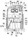
- FIG. 1is a vertical section through an embodiment of a first insertion device according to the present invention for insertion heads, in the non-pretensioned state and without an insertion head;
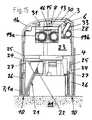
- FIG. 2is a view of the insertion device of FIG. 1 , but with an insertion head arranged in it;
- FIG. 3is a vertical section through the first insertion device in the pretensioned state, with an insertion head arranged in it in the secured state;
- FIG. 4is a view of the first insertion device of FIG. 3 , but in the released state;
- FIG. 5is a view of the first insertion device of FIG. 4 , but with the trigger buttons actuated at the moment of triggering;
- FIG. 6is a partial vertical section through another embodiment of an insertion device according to the present invention for insertion heads, in the non-pretensioned state and without an insertion head;
- FIG. 7is a view of the insertion device of FIG. 6 , but in the pretensioned, secured state;
- FIG. 8is a view of the insertion device of FIG. 7 , but with an insertion head designed as infusion set arranged in it, with the infusion cannula folded in;
- FIG. 9is a view of the insertion device of FIG. 8 , but with the infusion cannula folded out;
- FIG. 10is a perspective view, partially in vertical section, of the insertion device of FIG. 9 ;
- FIG. 11is a view of the insertion device of FIG. 9 , but in the released state, when placed and pressed onto the body of a patient;
- FIG. 12is a view of the insertion device of FIG. 11 , but directly after the application of the insertion head to the body of the patient;
- FIG. 13is a view of the insertion device of FIG. 12 , but upon removal from the body of the patient;
- FIG. 14is a partial vertical section through another embodiment of an insertion device according to the present invention for insertion heads, in the pretensioned and secured state, without an insertion head;
- FIG. 15is a view of the insertion device of FIG. 14 , but in the released state, when placed and pressed onto the body of a patient;
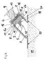
- FIG. 16is a vertical section through another embodiment of an insertion device according to the present invention in the pretensioned state, with an insertion head arranged in it in the secured state;
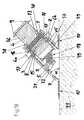
- FIG. 17is a vertical section through another embodiment of an insertion device according to the present invention in the pretensioned state, with an insertion head arranged in it in the secured state;
- FIG. 18is a vertical section through another embodiment of an insertion device according to the present invention in the pretensioned state, with an insertion head arranged in it in the secured state.
- fastening, mounting, attaching or connecting components of the present inventionunless specifically described as otherwise, conventional mechanical fasteners and methods may be used.
- Other appropriate fastening or attachment methodsinclude adhesives, welding and soldering, the latter particularly with regard to the electrical system of the invention, if any.
- suitable electrical components and circuitry, wires, wireless components, chips, boards, microprocessors, inputs, outputs, displays, control components, etc.may be used.
- the materials for making the invention and/or its componentsmay be selected from appropriate materials such as metal, metallic alloys, ceramics, plastics, etc.
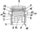
- FIGS. 1 to 5One embodiment of an insertion device according to the present invention is shown in vertical section in FIGS. 1 to 5 , in different states that arise during its intended use.
- the insertion devicecomprises a housing 1 , a piston-like thrust element 4 arranged displaceably in the housing 1 , and an energy-storing element designed as a helical spring 3 for driving the thrust element 4 .
- the thrust element 4has a receptacle 12 (see FIG. 1 ) for force-fit attachment of the insertion head which is to be applied with the insertion device and which, in the present example, is designed as an infusion set 2 (see FIG. 2 ), which receptacle forms a retention means.
- the infusion cannula 5(not visible here) is protected by a needle guard 14 , such that in this state the user is safely protected against injury by the cannula 5 .
- the thrust element 4On its top face, the thrust element 4 has a grip part 9 by which it can be drawn upwards relative to the housing 1 , counter to the spring force of the helical spring 3 , to pretension the helical spring 3 .
- the insertion devicealso comprises a first actuation member designed as a securing slide 7 , and also two further actuation members which are designed as trigger buttons 6 a , 6 b and whose actuation, in the situation illustrated, is blocked or prevented by the securing slide 7 .
- the securing slide 7On its top face, the securing slide 7 is spring-loaded in a downward direction by a restoring spring 13 with force direction. On its underside, it has a circular contact face 10 via which the insertion device is placed and pressed onto the body 11 of the patient upon application of the infusion set 2 .
- the release liner of the plaster 18is removed and the grip part 9 is pulled up such that the thrust element 4 is moved upward relative to the housing 1 counter to the force of the spring 3 , until two locking shoulders 8 formed by the thrust element 4 catch on locking lugs 15 formed on two spring arms 16 integral with the housing.
- the helical spring 3 and the thrust element 4are now ready in the pretensioned state and the infusion set 2 is in the first position, in which the infusion cannula 5 is arranged in the housing 1 in a set-back position relative to the contact face 10 .
- the cannula guard 14is now removed from the infusion cannula 5 , such that the arrangement made up of the insertion device and of the infusion set 2 arranged therein is ready for application. As will be seen, an actuation movement of the two trigger buttons 6 a , 6 b radially inward is still made impossible by the securing slide 7 .
- the insertion deviceis now pressed with the contact face 10 onto the application site on the body 11 of the patient, in such a way that the securing slide 7 slides into the housing 1 counter to the force of the restoring spring 13 and, in doing so, brings two openings 17 formed in it into alignment with the trigger buttons 6 a , 6 b , through which openings 17 the trigger buttons 6 a , 6 b can now move radially inward as far as the spring arms 16 .
- this statewhich is shown in FIG. 4 , the blocking or locking of the trigger buttons 6 a , 6 b has been cancelled.
- the infusion set 2has a fixing plaster 18 on its underside. This fixes it upon application to the patient's skin, such that, during the subsequent lifting of the insertion device from the body 11 of the patient, the infusion set 2 detaches itself from the receptacle 12 in the thrust element 4 and remains in the applied position on the body 11 of the patient.
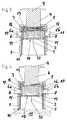
- FIGS. 6 to 13Another embodiment of an insertion device according to the present invention is shown in partial vertical section in FIGS. 6 to 13 , in different states that arise during its intended use, FIG. 10 showing a perspective view of the insertion device, partly in vertical section.
- this insertion devicecomprises a housing formed by two housing parts 1 a , 1 b that can be pushed together.
- a thrust element 4mounted in the upper housing part 1 b in such a way as to be vertically displaceable by two mechanically synchronized pivot lever pairs 19 a , 19 b , and, for each pivot lever pair 19 a , 19 b , a energy-storing element which is formed as a torsion spring or leg spring 3 and engages on the respective pivot lever pair 19 a , 1 9 b so as to drive the thrust element 4 forward.
- a thrust element 4mounted in the upper housing part 1 b in such a way as to be vertically displaceable by two mechanically synchronized pivot lever pairs 19 a , 19 b , and, for each pivot lever pair 19 a , 19 b , a energy-storing element which is formed as a torsion spring or leg spring 3 and engages on the respective pivot lever pair 19 a , 1 9 b so as to drive the thrust element 4 forward.
- the thrust element 4is arranged in the upper housing part 1 b with the torsion springs 3 pretensioned, the upper housing part 1 b , for temporary force-fit retention of the insertion head which is to be applied with the insertion device and which in this example is also designed as an infusion set 2 , comprises two opposite spring shackles 12 (only one of them is visible) which are fixed to the housing and serve as a retention means between which the infusion set 2 can be held, e.g. by clamping.
- the infusion set 2is in this case therefore held fixed in the upper housing part 1 b , and, in contrast to the preceding illustrative embodiment, is not movable relative to the housing in the thrust element 4 .
- the thrust element 4here lies with two jibs 20 a , 20 b on support faces of the lower housing part 1 a , such that, when the two housing halves 1 a , 1 b are pushed together starting from the position shown in FIG. 6 , it is pushed counter to the force of the torsion springs 3 into the upper housing part 1 b , and the locking lug 15 of a spring arm 16 arranged on its top face engages with a locking shoulder 8 in the upper housing part 1 b .
- the torsion springs 3 and the thrust element 4 driven by themare made ready in a pretensioned state.
- a suitable infusion set 2can now be fitted into the insertion device and can be secured in the upper housing part 1 b by being clamped between the two spring shackles 12 . This situation is shown in FIG. 8 .
- the present infusion set 2comprises an infusion cannula 5 that can be folded out.
- the infusion cannula 5is arranged hidden inside the two-part housing of the infusion set 2 upon introduction of the infusion set 2 into the pretensioned insertion device. If the two housing parts 1 a , 1 b of the insertion device are now drawn apart again, starting from the situation shown in FIG.
- FIGS. 9 and 10This situation, in which the infusion set 2 is located in a first position, is shown in FIGS. 9 and 10 .
- the two-part housing of the infusion set 2is pushed together by an inclined ramp surface 21 on the lower housing part 1 a being displaced vertically relative to a horizontally displaceable abutment element 22 , which is connected in terms of movement to the left-hand part of the two-part housing of the infusion set 2 , as a result of which the left-hand part of the two-part housing is pushed into the latter's right-hand housing part.
- an internal locking slide 23is coupled to the lower housing part 1 a , by locking lugs 24 , which are formed by spring arms 25 on the locking slide 23 and were previously arranged vertically displaceably in vertical guide slots 26 inside the lower housing part 1 a , coming into engagement with locking shoulders 27 of the lower housing part 1 a .
- locking lugs 24are formed by spring arms 25 on the locking slide 23 and were previously arranged vertically displaceably in vertical guide slots 26 inside the lower housing part 1 a , coming into engagement with locking shoulders 27 of the lower housing part 1 a .
- the locking slide 23blocks the actuation of an actuation member designed as trigger button 6 on the insertion device, since a securing shoulder 29 of the locking slide 23 makes it impossible for a guide ram 28 , connected rigidly to the trigger button 6 , to move in the actuation direction.
- the fact that the locking slide 23 has only a relatively small displacement travelmeans that, in this state, it is at the same time guaranteed that the two housing parts 1 a , 1 b cannot be pushed so far together that the infusion cannula 5 protrudes beyond the contact faces 10 , which might lead to a risk of injury.
- This situationis shown in FIG. 11 , in which the partial pushing together of the two housing parts 1 a , 1 b , which permits the displacement of the locking slide 23 and therefore the release of the trigger button 6 , is achieved by pressing the insertion device onto the body 11 of a patient via the contact faces 10 formed on the underside of the lower housing part 1 a . After the engagement with the securing slide 23 , the lower housing part 1 a thus forms a first actuation member 7 .
- the trigger ram 30presses the locking lug 15 of the thrust element 4 to the left, under elastic bending of the spring arm 16 , until the locking lug 15 disengages from the locking shoulder 8 of the upper housing part 1 b , and the thrust element 4 shoots downwards, guided by the two pivot lever pairs 19 a , 19 b and driven by the force of the pretensioned torsion springs 3 .
- the thrust elementforcibly hits the infusion set 2 held between the spring shackles 12 and catapults it onto the application site with complete insertion of the infusion cannula 5 into the body 11 of the patient, while the fixing plaster 18 arranged on its underside simultaneously fixes it to the skin of the patient.
- FIG. 12This situation, in which the infusion set 2 is already separated from the insertion device, is shown in FIG. 12 . If the insertion device is now removed from the body 11 of the patient and the actuation of the trigger button 6 is cancelled, the trigger button 6 , under the effect of a restoring spring 33 (shown only in FIGS.
- insertion headsare shown which are designed as infusion sets 2 with a flexible cannula 5 (soft cannula), said flexible cannulas being supported in each case by a guide needle 32 .
- these guide needles 32together with a component of the originally applied infusion set 2 connected to them, are removed (not shown here), and an infusion line is then connected to the remaining applied infusion set 2 for the purpose of delivering an infusion liquid into the body 11 of the patient.
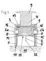
- FIGS. 14 and 15show another embodiment of the insertion device according to the present invention in partial vertical section, first in the pretensioned and secured state, and second in the released state when placed and pressed onto the body 11 of a patient.
- This embodimentgenerally corresponds to the second embodiment shown in FIGS. 6 to 13 , and the operating states shown correspond to the states shown in FIGS. 9 and 11 , except that, to simplify the illustration, no insertion head is shown here in the insertion device.
- FIGS. 14 and 15A difference between the embodiment of FIGS. 14 and 15 and the above-described second embodiment is that the actuation button 6 is in this case not blocked by its guide ram 28 being blocked by the locking slide 23 . Instead the deflection of the spring arm 16 of the thrust element 4 is cancelled by an abutment element 31 formed on the locking slide 23 , as long as the locking slide 23 is located in the securing position, such that its locking lug 15 cannot be disengaged from the locking shoulder 8 of the upper housing part 1 b . This situation is shown in FIG. 14 .
- the locking slide 23is now displaced upward in the upper housing part 1 b by the insertion device being pressed via the contact faces 10 of the lower housing part 1 a onto the body 11 of a patient, the abutment element 31 frees the spring arm 16 , such that the locking lug 15 thereof can be disengaged from the locking shoulder 8 by pressing the actuation button 6 , so as to trigger the insertion device.
- All the other functions and modes of operationare identical to those described in connection with the second illustrative embodiment.
- FIG. 16shows a vertical section through another embodiment of an insertion device according to the present invention in the pretensioned state, with an infusion set 2 arranged in it in the secured state.
- the insertion device of this embodimentdiffers from the insertion device of the FIGS. 1 to 5 in that it is adapted for the inclined application of an infusion set especially adapted for such an application, i.e. the direction of introduction of the cannula 5 and of the guide needle 32 forms together with the skin surface at the application site an angle a smaller than 90°.
- this angle ⁇may be in the range between 20° and 45°. In the illustrated embodiment, it is 45°.
- FIG. 17shows a vertical section through another embodiment of an insertion device according to the present invention in the pretensioned state, with an infusion set 2 arranged in it in the secured state.
- This insertion devicediffers from the insertion device of FIG. 16 in that the infusion set 2 is not attached to the thrust element 4 but is held by an adapter 34 and a frame 35 in the housing 1 of the insertion device.
- the adapter 34 in this embodimentbasically is a disc-shaped element with a circumferential groove.
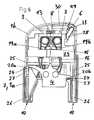
- FIG. 18shows a vertical section through another embodiment of an insertion device according to the present invention in the pretensioned state, with an infusion set 2 arranged in it in the secured state.
- This insertion devicediffers from the insertion device of FIG. 16 in that it is adapted for infusion sets 2 with tiltable cannula 5 and insertion needle 32 , which in the situation illustrated in FIG. 18 have already been tilted from a folded-in state, in which the cannula 5 and the insertion needle 32 are hidden inside the housing of the infusion set 2 , into the shown folded-out state.
- the infusion set 2 in this embodimentis not attached to the thrust element 4 but is held by a clamping sleeve 36 which holds the infusion set 2 by several spring arms 37 .
- the thrust element 4is arranged within the clamping sleeve 36 and with two grip parts 9 radially protrudes through the sleeve 36 .
- the clamping sleeve 36 together with the thrust element 4is in a foremost position within the housing 1 .
- the thrust element 4 and the clamping sleeve 36are by means of the grip parts 9 retracted until the clamping sleeve 36 engages at the housing 1 with catches 38 formed at its inner side.
- the two-part housing of the infusion set 2is pushed together by an inclined ramp surface 21 arranged at the inner side of the housing 1 , whereby the infusion cannula 5 and the insertion needle 32 are folded out by an internal mechanism of the infusion set 2 .
- the thrust element 4upon release and actuation of the trigger buttons 6 a , 6 b , is driven downward by the force of the spring 3 , it spreads the spring arms 37 by contacting cam elements 39 arranged at the inner sides thereof, thereby releasing the infusion set 2 , and forcibly hits the infusion set 2 and catapults it onto the application site.
- the cannulla 5 with the insertion needle 32is completely inserted into the body 11 of the patient.
- the insertion heads to be applied in the above illustrative embodimentsare designed as infusion sets, it should once again be clearly noted that the insertion devices shown are also suitable for the application of other insertion heads, for example heads designed as a port or sensor arrangement or as a combination of a sensor arrangement and a port or infusion set, and that the invention is suitable for any conceivable insertion heads that can be applied by introducing a needle-like or blade-like element into the body of a patient.
Landscapes
- Health & Medical Sciences (AREA)
- Life Sciences & Earth Sciences (AREA)
- Animal Behavior & Ethology (AREA)
- Engineering & Computer Science (AREA)
- Anesthesiology (AREA)
- Biomedical Technology (AREA)
- Heart & Thoracic Surgery (AREA)
- Hematology (AREA)
- General Health & Medical Sciences (AREA)
- Public Health (AREA)
- Veterinary Medicine (AREA)
- Pulmonology (AREA)
- Biophysics (AREA)
- Vascular Medicine (AREA)
- Infusion, Injection, And Reservoir Apparatuses (AREA)
Abstract
Description
Claims (19)
Applications Claiming Priority (3)
| Application Number | Priority Date | Filing Date | Title |
|---|---|---|---|
| CH1349/06 | 2006-08-24 | ||
| CH13492006 | 2006-08-24 | ||
| PCT/CH2007/000400WO2008022476A1 (en) | 2006-08-24 | 2007-08-16 | Insertion device for insertion heads, in particular for infusion sets |
Related Parent Applications (1)
| Application Number | Title | Priority Date | Filing Date |
|---|---|---|---|
| PCT/CH2007/000400ContinuationWO2008022476A1 (en) | 2006-08-24 | 2007-08-16 | Insertion device for insertion heads, in particular for infusion sets |
Publications (2)
| Publication Number | Publication Date |
|---|---|
| US20090216215A1 US20090216215A1 (en) | 2009-08-27 |
| US8870822B2true US8870822B2 (en) | 2014-10-28 |
Family
ID=38596829
Family Applications (1)
| Application Number | Title | Priority Date | Filing Date |
|---|---|---|---|
| US12/391,513Active2028-03-02US8870822B2 (en) | 2006-08-24 | 2009-02-24 | Insertion device for insertion heads and infusion sets |
Country Status (7)
| Country | Link |
|---|---|
| US (1) | US8870822B2 (en) |
| EP (1) | EP2054109B1 (en) |
| JP (1) | JP2010501211A (en) |
| CN (1) | CN101505816B (en) |
| CA (1) | CA2660392A1 (en) |
| DK (1) | DK2054109T3 (en) |
| WO (1) | WO2008022476A1 (en) |
Cited By (28)
| Publication number | Priority date | Publication date | Assignee | Title |
|---|---|---|---|---|
| EP2549918B1 (en) | 2010-03-24 | 2016-06-29 | Abbott Diabetes Care, Inc. | Medical device inserters and processes of inserting and using medical devices |
| US9931066B2 (en) | 2011-12-11 | 2018-04-03 | Abbott Diabetes Care Inc. | Analyte sensor devices, connections, and methods |
| US9993188B2 (en) | 2009-02-03 | 2018-06-12 | Abbott Diabetes Care Inc. | Analyte sensor and apparatus for insertion of the sensor |
| US10213139B2 (en) | 2015-05-14 | 2019-02-26 | Abbott Diabetes Care Inc. | Systems, devices, and methods for assembling an applicator and sensor control device |
| US10674944B2 (en) | 2015-05-14 | 2020-06-09 | Abbott Diabetes Care Inc. | Compact medical device inserters and related systems and methods |
| US10863944B2 (en) | 2017-06-23 | 2020-12-15 | Dexcom, Inc. | Transcutaneous analyte sensors, applicators therefor, and associated methods |
| US10898115B2 (en) | 2015-12-30 | 2021-01-26 | Dexcom, Inc. | Transcutaneous analyte sensor systems and methods |
| USD924406S1 (en) | 2010-02-01 | 2021-07-06 | Abbott Diabetes Care Inc. | Analyte sensor inserter |
| USD926325S1 (en) | 2018-06-22 | 2021-07-27 | Dexcom, Inc. | Wearable medical monitoring device |
| US11071478B2 (en) | 2017-01-23 | 2021-07-27 | Abbott Diabetes Care Inc. | Systems, devices and methods for analyte sensor insertion |
| US11160926B1 (en) | 2007-10-09 | 2021-11-02 | Dexcom, Inc. | Pre-connected analyte sensors |
| US11331022B2 (en) | 2017-10-24 | 2022-05-17 | Dexcom, Inc. | Pre-connected analyte sensors |
| US11350862B2 (en) | 2017-10-24 | 2022-06-07 | Dexcom, Inc. | Pre-connected analyte sensors |
| USD961778S1 (en) | 2006-02-28 | 2022-08-23 | Abbott Diabetes Care Inc. | Analyte sensor device |
| USD962446S1 (en) | 2009-08-31 | 2022-08-30 | Abbott Diabetes Care, Inc. | Analyte sensor device |
| USD979766S1 (en) | 2005-09-30 | 2023-02-28 | Abbott Diabetes Care Inc. | Analyte sensor device |
| USD982762S1 (en) | 2020-12-21 | 2023-04-04 | Abbott Diabetes Care Inc. | Analyte sensor inserter |
| US11627900B2 (en) | 2003-12-05 | 2023-04-18 | Dexcom, Inc. | Analyte sensor |
| US11633128B2 (en) | 2019-08-02 | 2023-04-25 | Bionime Corporation | Method for assembling a physiological signal monitoring device |
| US11678846B2 (en) | 2019-08-02 | 2023-06-20 | Bionime Corporation | Insertion device for a biosensor |
| USD1002852S1 (en) | 2019-06-06 | 2023-10-24 | Abbott Diabetes Care Inc. | Analyte sensor device |
| US11896804B2 (en) | 2019-08-02 | 2024-02-13 | Bionime Corporation | Insertion device for a biosensor and insertion method thereof |
| US12239463B2 (en) | 2020-08-31 | 2025-03-04 | Abbott Diabetes Care Inc. | Systems, devices, and methods for analyte sensor insertion |
| US12274548B2 (en) | 2006-10-23 | 2025-04-15 | Abbott Diabetes Care Inc. | Sensor insertion devices and methods of use |
| US12318200B2 (en) | 2008-11-07 | 2025-06-03 | Dexcom, Inc. | Analyte sensor |
| US12403260B2 (en) | 2019-08-02 | 2025-09-02 | Bionime Corporation | Insertion device for a biosensor and insertion method thereof |
| US12408847B2 (en) | 2018-06-07 | 2025-09-09 | Abbott Diabetes Care Inc. | Focused sterilization and sterilized sub-assemblies for analyte monitoring systems |
| US12427253B2 (en) | 2019-08-02 | 2025-09-30 | Bionime Corporation | Insertion device for a biosensor and insertion method thereof |
Families Citing this family (62)
| Publication number | Priority date | Publication date | Assignee | Title |
|---|---|---|---|---|
| US7731691B2 (en) | 2003-11-10 | 2010-06-08 | Smiths Medical Asd, Inc. | Subcutaneous infusion device and device for insertion of a cannula of an infusion device and method |
| ES2820335T3 (en) | 2007-04-16 | 2021-04-20 | Corium Inc | Solvent Cast Microneedle Arrays Containing Active Agent |
| WO2009048607A1 (en) | 2007-10-10 | 2009-04-16 | Corium International, Inc. | Vaccine delivery via microneedle arrays |
| US9295786B2 (en) | 2008-05-28 | 2016-03-29 | Medtronic Minimed, Inc. | Needle protective device for subcutaneous sensors |
| GB2461088B (en) | 2008-06-19 | 2012-09-26 | Cilag Gmbh Int | Injection device |
| ATE553800T1 (en)* | 2009-11-26 | 2012-05-15 | Hoffmann La Roche | EXTERNALLY TRIGGERABLE CANNULA ARRANGEMENT |
| WO2011140274A2 (en) | 2010-05-04 | 2011-11-10 | Corium International, Inc. | Method and device for transdermal delivery of parathyroid hormone using a microprojection array |
| WO2011160244A1 (en)* | 2010-06-21 | 2011-12-29 | F. Hoffmann-La Roche Ag | Device for inserting an insertion member into the tissue of the body of a patient |
| JP5885667B2 (en) | 2010-10-07 | 2016-03-15 | 久光製薬株式会社 | applicator |
| US9707335B2 (en) | 2011-09-02 | 2017-07-18 | Unitract Syringe Pty Ltd | Drive mechanism for drug delivery pumps with integrated status indication |
| US11173244B2 (en) | 2011-09-02 | 2021-11-16 | Unl Holdings Llc | Drive mechanism for drug delivery pumps with integrated status indication |
| CA2845379C (en) | 2011-09-02 | 2019-08-06 | Unitract Syringe Pty Ltd | Insertion mechanism for a drug delivery pump |
| EP2731641B1 (en) | 2011-09-02 | 2021-09-29 | UNL Holdings LLC | Drive mechanism for drug delivery pumps with integrated status indication |
| US9814832B2 (en) | 2011-09-02 | 2017-11-14 | Unl Holdings Llc | Drive mechanism for drug delivery pumps with integrated status indication |
| ES2566179T5 (en) | 2011-09-13 | 2019-11-14 | Unitract Syringe Pty Ltd | Connection of sterile fluid passage to medication containers for medication release pumps |
| EP2764887B1 (en) | 2011-10-06 | 2020-12-02 | Hisamitsu Pharmaceutical Co., Inc. | Applicator |
| EP2650032A1 (en)* | 2012-04-11 | 2013-10-16 | PharmaSens AG | Subcutaneous needle insertion mechanism |
| EP2858699A1 (en)* | 2012-06-09 | 2015-04-15 | Roche Diagnostics GmbH | Disposable inserter for use with a medical device |
| ES2637229T3 (en) | 2012-08-29 | 2017-10-11 | Unitract Syringe Pty Ltd | Controlled drive mechanisms for medication delivery pumps |
| EP2703029A1 (en) | 2012-09-04 | 2014-03-05 | Sanofi-Aventis Deutschland GmbH | Medicament delivery device with alignment mechanism |
| US9782538B2 (en)* | 2012-09-27 | 2017-10-10 | Becton, Dickinson And Company | Angled inserter for drug infusion |
| EP2716317A1 (en) | 2012-10-04 | 2014-04-09 | Sanofi-Aventis Deutschland GmbH | Medicament delivery device with trigger button |
| BR112015014969B1 (en) | 2012-12-21 | 2021-12-07 | Corium, Inc | MICROSTRUCTURE APPARATUS AND METHOD OF MANUFACTURING A MICROSTRUCTURE APPARATUS |
| US9802030B2 (en) | 2013-01-25 | 2017-10-31 | Unl Holdings Llc | Integrated sliding seal fluid pathway connection and drug containers for drug delivery pumps |
| USD723157S1 (en) | 2013-03-12 | 2015-02-24 | Unitract Syringe Pty Ltd | Drug delivery pump |
| EP2968887B1 (en)* | 2013-03-12 | 2022-05-04 | Corium, Inc. | Microprojection applicators |
| US10080839B2 (en) | 2013-03-14 | 2018-09-25 | Becton, Dickinson And Company | Angled inserter for drug infusion |
| CA2903763C (en) | 2013-03-15 | 2021-11-16 | Corium International, Inc. | Microarray with polymer-free microstructures, methods of making, and methods of use |
| ES2939317T3 (en) | 2013-03-15 | 2023-04-20 | Corium Pharma Solutions Inc | Multi-impact micro-spray applicators |
| BR112015022625B1 (en) | 2013-03-15 | 2023-01-31 | Corium, Inc | MICROSTRUCTURE DEVICE FOR DELIVERY OF THERAPEUTIC AGENT |
| EP2968771A4 (en)* | 2013-03-15 | 2017-02-15 | University Hospitals Case Medical Center | Subcutaneous hydration system, method, and device |
| AU2014233541B2 (en) | 2013-03-15 | 2018-11-22 | Corium Pharma Solutions, Inc. | Microarray for delivery of therapeutic agent, methods of use, and methods of making |
| US9821113B2 (en)* | 2013-03-15 | 2017-11-21 | Becton, Dickinson And Company | Automatic angled infusion set assembly |
| US10478569B2 (en)* | 2013-04-07 | 2019-11-19 | Repro-Med Systems, Inc. | Needle insertion device |
| US11559635B2 (en)* | 2015-10-07 | 2023-01-24 | Repro-Med Systems, Inc. | Needle insertion device |
| US11883638B2 (en)* | 2013-04-07 | 2024-01-30 | Koru Medical Systems, Inc. | Needle insertion device |
| WO2014178140A1 (en)* | 2013-05-02 | 2014-11-06 | Asti株式会社 | Microneedle array and microneedle array device |
| AU2014308659B2 (en) | 2013-08-23 | 2018-11-01 | Unl Holdings Llc | Integrated pierceable seal fluid pathway connection and drug containers for drug delivery pumps |
| WO2015136639A1 (en) | 2014-03-12 | 2015-09-17 | 株式会社バイオセレンタック | Micro-needle preparation administration member for intradermal placement of target substance and apparatus for rapid administration of micro-needle preparation |
| CH709930A2 (en) | 2014-07-29 | 2016-01-29 | Tecpharma Licensing Ag | Insertion device for an infusion. |
| US10624843B2 (en) | 2014-09-04 | 2020-04-21 | Corium, Inc. | Microstructure array, methods of making, and methods of use |
| EP3200851A1 (en) | 2014-09-29 | 2017-08-09 | Unitract Syringe Pty Ltd | Rigid needle insertion mechanism for a drug delivery pump |
| WO2016065190A1 (en) | 2014-10-23 | 2016-04-28 | Abbott Diabetes Care Inc. | Electrodes having at least one sensing structure and methods for making and using the same |
| WO2017004067A1 (en) | 2015-06-29 | 2017-01-05 | Corium International, Inc. | Microarray for delivery of therapeutic agent, methods of use, and methods of making |
| US9827369B2 (en)* | 2016-03-16 | 2017-11-28 | Baxter International Inc. | Percutaneous administration device and method for injecting medicinal substances |
| EP4442297A3 (en)* | 2016-04-29 | 2025-01-01 | ICU Medical, Inc. | Subcutaneous insertion systems, devices and related methods |
| IL264404B (en) | 2016-08-08 | 2022-07-01 | Unitract Syringe Pty Ltd | Drug delivery device and method for connecting a fluid flow path |
| WO2018060023A1 (en)* | 2016-09-27 | 2018-04-05 | Sanofi-Aventis Deutschland Gmbh | A medicament delivery device |
| CN108205058B (en)* | 2016-12-20 | 2023-04-11 | 天津果实科技有限公司 | Urine test stick ejection device and method |
| EP3618712A1 (en) | 2017-05-03 | 2020-03-11 | Abbott Diabetes Care Inc. | Systems, devices, and methods with duration-based adjustment of sensor data |
| CN107320811A (en)* | 2017-08-15 | 2017-11-07 | 郑州蒙纳瑞医疗设备有限公司 | A kind of repeatable remain-type subcutaneous infusion set utilized |
| US11918348B2 (en) | 2017-12-05 | 2024-03-05 | Abbott Diabetes Care Inc. | Medical devices having a dynamic surface profile and methods for production and use thereof |
| CN108187194A (en)* | 2017-12-07 | 2018-06-22 | 新乡医学院 | A kind of needle cap device for popping up novopen syringe needle |
| DE102018101283A1 (en)* | 2018-01-22 | 2019-07-25 | Eyesense Gmbh | Injector for transcutaneously introducing a sensor into a patient |
| EP4218567B1 (en) | 2018-06-07 | 2025-03-12 | Abbott Diabetes Care, Inc. | Focused sterilization and sterilized sub-assemblies for analyte monitoring systems |
| US11213665B2 (en)* | 2018-06-15 | 2022-01-04 | Esthetic Education LLC | Angled microneedle cartridge |
| CA3126999A1 (en)* | 2019-02-22 | 2020-08-27 | Deka Products Limited Partnership | Infusion set and inserter assembly systems and methods |
| EP4021553A1 (en)* | 2019-08-27 | 2022-07-06 | LTS Lohmann Therapie-Systeme AG | Microarray applicator and method for moving a plunger which acts on the microarray |
| CN113082362B (en)* | 2021-03-26 | 2022-09-20 | 普昂(杭州)健康管理有限公司 | Split type subcutaneous soft needle and puncture method |
| CN116509334A (en)* | 2023-05-31 | 2023-08-01 | 希捷姆医疗技术(深圳)有限公司 | Needle aid |
| US20250195758A1 (en)* | 2023-12-18 | 2025-06-19 | Koru Medical Systems, Inc. | System and method for administering a butterfly needle to a patient |
| CN117444614B (en)* | 2023-12-22 | 2024-03-22 | 佳木斯大学 | Medical instrument assembling device and use method thereof |
Citations (12)
| Publication number | Priority date | Publication date | Assignee | Title |
|---|---|---|---|---|
| US4403989A (en)* | 1981-09-14 | 1983-09-13 | Syntex (U.S.A.) Inc. | Injection device |
| US20040158207A1 (en)* | 2001-04-06 | 2004-08-12 | Marcel Hunn | Infusion set |
| WO2004110527A1 (en) | 2003-06-12 | 2004-12-23 | Disetronic Licensing Ag | Insertion device for infusion sets |
| US20050101912A1 (en)* | 2003-11-10 | 2005-05-12 | Mark Faust | Device and method for insertion of a cannula of an infusion device |
| US20050131347A1 (en)* | 2003-05-09 | 2005-06-16 | Medsolve Technologies, Llc | Apparatus for delivery of therapeutic and/or diagnostic agents |
| US20050283114A1 (en)* | 2004-06-16 | 2005-12-22 | Timothy Bresina | Device and method for insertion of a cannula of an infusion device |
| US20060069351A9 (en)* | 1997-02-05 | 2006-03-30 | Medtronic Minimed, Inc. | Insertion device for an insertion set and method of using the same |
| EP1704889A1 (en) | 2004-01-16 | 2006-09-27 | Kabushiki Kaisha Top | Indwelling needle |
| EP1764125A1 (en) | 2005-09-15 | 2007-03-21 | F.Hoffmann-La Roche Ag | System comprising an insertion head and an inserter |
| US8303545B2 (en)* | 2007-09-07 | 2012-11-06 | Stat Medical Devices, Inc. | Infusion device and method of using and making the same |
| US8475410B2 (en)* | 2009-11-26 | 2013-07-02 | Roche Diagnostics International Ag | Externally triggerable cannula assembly |
| US8696625B2 (en)* | 2005-04-20 | 2014-04-15 | Becton Dickinson France | Injection set and injection assistance device |
Family Cites Families (2)
| Publication number | Priority date | Publication date | Assignee | Title |
|---|---|---|---|---|
| US5478316A (en)* | 1994-02-02 | 1995-12-26 | Becton, Dickinson And Company | Automatic self-injection device |
| DE20320207U1 (en)* | 2003-06-12 | 2004-10-14 | Disetronic Licensing Ag | Insertion device for an infusion set comprises a thrust linkage which is constituted so that the forward motion of the set takes place without a sliding contact with the device housing |
- 2007
- 2007-08-16JPJP2009524858Apatent/JP2010501211A/enactivePending
- 2007-08-16EPEP07785095.6Apatent/EP2054109B1/enactiveActive
- 2007-08-16DKDK07785095.6Tpatent/DK2054109T3/enactive
- 2007-08-16WOPCT/CH2007/000400patent/WO2008022476A1/enactiveApplication Filing
- 2007-08-16CACA002660392Apatent/CA2660392A1/ennot_activeAbandoned
- 2007-08-16CNCN2007800312853Apatent/CN101505816B/enactiveActive
- 2009
- 2009-02-24USUS12/391,513patent/US8870822B2/enactiveActive
Patent Citations (13)
| Publication number | Priority date | Publication date | Assignee | Title |
|---|---|---|---|---|
| US4403989A (en)* | 1981-09-14 | 1983-09-13 | Syntex (U.S.A.) Inc. | Injection device |
| US20060069351A9 (en)* | 1997-02-05 | 2006-03-30 | Medtronic Minimed, Inc. | Insertion device for an insertion set and method of using the same |
| US20040158207A1 (en)* | 2001-04-06 | 2004-08-12 | Marcel Hunn | Infusion set |
| US20050131347A1 (en)* | 2003-05-09 | 2005-06-16 | Medsolve Technologies, Llc | Apparatus for delivery of therapeutic and/or diagnostic agents |
| WO2004110527A1 (en) | 2003-06-12 | 2004-12-23 | Disetronic Licensing Ag | Insertion device for infusion sets |
| US20060135908A1 (en)* | 2003-06-12 | 2006-06-22 | Jurg Liniger | Insertion device for infusion sets |
| US20050101912A1 (en)* | 2003-11-10 | 2005-05-12 | Mark Faust | Device and method for insertion of a cannula of an infusion device |
| EP1704889A1 (en) | 2004-01-16 | 2006-09-27 | Kabushiki Kaisha Top | Indwelling needle |
| US20050283114A1 (en)* | 2004-06-16 | 2005-12-22 | Timothy Bresina | Device and method for insertion of a cannula of an infusion device |
| US8696625B2 (en)* | 2005-04-20 | 2014-04-15 | Becton Dickinson France | Injection set and injection assistance device |
| EP1764125A1 (en) | 2005-09-15 | 2007-03-21 | F.Hoffmann-La Roche Ag | System comprising an insertion head and an inserter |
| US8303545B2 (en)* | 2007-09-07 | 2012-11-06 | Stat Medical Devices, Inc. | Infusion device and method of using and making the same |
| US8475410B2 (en)* | 2009-11-26 | 2013-07-02 | Roche Diagnostics International Ag | Externally triggerable cannula assembly |
Cited By (92)
| Publication number | Priority date | Publication date | Assignee | Title |
|---|---|---|---|---|
| US11627900B2 (en) | 2003-12-05 | 2023-04-18 | Dexcom, Inc. | Analyte sensor |
| USD979766S1 (en) | 2005-09-30 | 2023-02-28 | Abbott Diabetes Care Inc. | Analyte sensor device |
| USD961778S1 (en) | 2006-02-28 | 2022-08-23 | Abbott Diabetes Care Inc. | Analyte sensor device |
| US12274548B2 (en) | 2006-10-23 | 2025-04-15 | Abbott Diabetes Care Inc. | Sensor insertion devices and methods of use |
| US11160926B1 (en) | 2007-10-09 | 2021-11-02 | Dexcom, Inc. | Pre-connected analyte sensors |
| US12318200B2 (en) | 2008-11-07 | 2025-06-03 | Dexcom, Inc. | Analyte sensor |
| US11202591B2 (en) | 2009-02-03 | 2021-12-21 | Abbott Diabetes Care Inc. | Analyte sensor and apparatus for insertion of the sensor |
| US11006872B2 (en) | 2009-02-03 | 2021-05-18 | Abbott Diabetes Care Inc. | Analyte sensor and apparatus for insertion of the sensor |
| USD957642S1 (en) | 2009-02-03 | 2022-07-12 | Abbott Diabetes Care Inc. | Analyte sensor inserter |
| USD955599S1 (en) | 2009-02-03 | 2022-06-21 | Abbott Diabetes Care Inc. | Analyte sensor inserter |
| US10786190B2 (en) | 2009-02-03 | 2020-09-29 | Abbott Diabetes Care Inc. | Analyte sensor and apparatus for insertion of the sensor |
| US11213229B2 (en) | 2009-02-03 | 2022-01-04 | Abbott Diabetes Care Inc. | Analyte sensor and apparatus for insertion of the sensor |
| US11006870B2 (en) | 2009-02-03 | 2021-05-18 | Abbott Diabetes Care Inc. | Analyte sensor and apparatus for insertion of the sensor |
| USD957643S1 (en) | 2009-02-03 | 2022-07-12 | Abbott Diabetes Care Inc. | Analyte sensor device |
| USD882432S1 (en) | 2009-02-03 | 2020-04-28 | Abbott Diabetes Care Inc. | Analyte sensor on body unit |
| US11006871B2 (en) | 2009-02-03 | 2021-05-18 | Abbott Diabetes Care Inc. | Analyte sensor and apparatus for insertion of the sensor |
| US9993188B2 (en) | 2009-02-03 | 2018-06-12 | Abbott Diabetes Care Inc. | Analyte sensor and apparatus for insertion of the sensor |
| US11166656B2 (en) | 2009-02-03 | 2021-11-09 | Abbott Diabetes Care Inc. | Analyte sensor and apparatus for insertion of the sensor |
| USD962446S1 (en) | 2009-08-31 | 2022-08-30 | Abbott Diabetes Care, Inc. | Analyte sensor device |
| USD924406S1 (en) | 2010-02-01 | 2021-07-06 | Abbott Diabetes Care Inc. | Analyte sensor inserter |
| US11064922B1 (en) | 2010-03-24 | 2021-07-20 | Abbott Diabetes Care Inc. | Medical device inserters and processes of inserting and using medical devices |
| US10881340B2 (en) | 2010-03-24 | 2021-01-05 | Abbott Diabetes Care Inc. | Medical device inserters and processes of inserting and using medical devices |
| USD997362S1 (en) | 2010-03-24 | 2023-08-29 | Abbott Diabetes Care Inc. | Analyte sensor inserter |
| US11000216B2 (en) | 2010-03-24 | 2021-05-11 | Abbott Diabetes Care Inc. | Medical device inserters and processes of inserting and using medical devices |
| US10959654B2 (en) | 2010-03-24 | 2021-03-30 | Abbott Diabetes Care Inc. | Medical device inserters and processes of inserting and using medical devices |
| US11013440B2 (en) | 2010-03-24 | 2021-05-25 | Abbott Diabetes Care Inc. | Medical device inserters and processes of inserting and using medical devices |
| EP2549918B1 (en) | 2010-03-24 | 2016-06-29 | Abbott Diabetes Care, Inc. | Medical device inserters and processes of inserting and using medical devices |
| USD948722S1 (en) | 2010-03-24 | 2022-04-12 | Abbott Diabetes Care Inc. | Analyte sensor inserter |
| US10952657B2 (en) | 2010-03-24 | 2021-03-23 | Abbott Diabetes Care Inc. | Medical device inserters and processes of inserting and using medical devices |
| US11058334B1 (en) | 2010-03-24 | 2021-07-13 | Abbott Diabetes Care Inc. | Medical device inserters and processes of inserting and using medical devices |
| US9687183B2 (en) | 2010-03-24 | 2017-06-27 | Abbott Diabetes Care Inc. | Medical device inserters and processes of inserting and using medical devices |
| EP2549918B2 (en)† | 2010-03-24 | 2023-01-25 | Abbott Diabetes Care, Inc. | Medical device inserters and processes of inserting and using medical devices |
| US11266335B2 (en) | 2010-03-24 | 2022-03-08 | Abbott Diabetes Care Inc. | Medical device inserters and processes of inserting and using medical devices |
| US10945649B2 (en) | 2010-03-24 | 2021-03-16 | Abbott Diabetes Care Inc. | Medical device inserters and processes of inserting and using medical devices |
| US10010280B2 (en) | 2010-03-24 | 2018-07-03 | Abbott Diabetes Care Inc. | Medical device inserters and processes of inserting and using medical devices |
| US10772547B1 (en) | 2010-03-24 | 2020-09-15 | Abbott Diabetes Care Inc. | Medical device inserters and processes of inserting and using medical devices |
| USD987830S1 (en) | 2010-03-24 | 2023-05-30 | Abbott Diabetes Care Inc. | Analyte sensor inserter |
| US11246519B2 (en) | 2010-03-24 | 2022-02-15 | Abbott Diabetes Care Inc. | Medical device inserters and processes of inserting and using medical devices |
| US10881341B1 (en) | 2010-03-24 | 2021-01-05 | Abbott Diabetes Care Inc. | Medical device inserters and processes of inserting and using medical devices |
| US10292632B2 (en) | 2010-03-24 | 2019-05-21 | Abbott Diabetes Care Inc. | Medical device inserters and processes of inserting and using medical devices |
| US12343143B2 (en) | 2011-04-15 | 2025-07-01 | Dexcom, Inc. | Advanced analyte sensor calibration and error detection |
| US11179068B2 (en) | 2011-12-11 | 2021-11-23 | Abbott Diabetes Care Inc. | Analyte sensor devices, connections, and methods |
| US9931066B2 (en) | 2011-12-11 | 2018-04-03 | Abbott Diabetes Care Inc. | Analyte sensor devices, connections, and methods |
| US11051725B2 (en) | 2011-12-11 | 2021-07-06 | Abbott Diabetes Care Inc. | Analyte sensor devices, connections, and methods |
| USD1051397S1 (en) | 2011-12-11 | 2024-11-12 | Abbott Diabetes Care Inc. | Analyte sensor device |
| US11051724B2 (en) | 2011-12-11 | 2021-07-06 | Abbott Diabetes Care Inc. | Analyte sensor devices, connections, and methods |
| USD915602S1 (en) | 2011-12-11 | 2021-04-06 | Abbott Diabetes Care Inc. | Analyte sensor device |
| USD1036674S1 (en) | 2011-12-11 | 2024-07-23 | Abbott Diabetes Care Inc. | Analyte sensor device |
| USD915601S1 (en) | 2011-12-11 | 2021-04-06 | Abbott Diabetes Care Inc. | Analyte sensor device |
| US10674944B2 (en) | 2015-05-14 | 2020-06-09 | Abbott Diabetes Care Inc. | Compact medical device inserters and related systems and methods |
| US10213139B2 (en) | 2015-05-14 | 2019-02-26 | Abbott Diabetes Care Inc. | Systems, devices, and methods for assembling an applicator and sensor control device |
| USD980986S1 (en) | 2015-05-14 | 2023-03-14 | Abbott Diabetes Care Inc. | Analyte sensor inserter |
| US11375932B2 (en) | 2015-12-30 | 2022-07-05 | Dexcom, Inc. | Transcutaneous analyte sensor systems and methods |
| US11331021B2 (en) | 2015-12-30 | 2022-05-17 | Dexcom, Inc. | Transcutaneous analyte sensor systems and methods |
| US11166657B2 (en) | 2015-12-30 | 2021-11-09 | Dexcom, Inc. | Transcutaneous analyte sensor systems and methods |
| US11642055B2 (en) | 2015-12-30 | 2023-05-09 | Dexcom, Inc. | Transcutaneous analyte sensor systems and methods |
| US11412966B2 (en) | 2015-12-30 | 2022-08-16 | Dexcom, Inc. | Transcutaneous analyte sensor systems and methods |
| US10898115B2 (en) | 2015-12-30 | 2021-01-26 | Dexcom, Inc. | Transcutaneous analyte sensor systems and methods |
| US11602291B2 (en) | 2015-12-30 | 2023-03-14 | Dexcom, Inc. | Transcutaneous analyte sensor systems and methods |
| US12279865B2 (en) | 2015-12-30 | 2025-04-22 | Dexcom, Inc. | Transcutaneous analyte sensor systems and methods |
| US12268496B2 (en) | 2017-01-23 | 2025-04-08 | Abbott Diabetes Care Inc. | Systems, devices and methods for analyte sensor insertion |
| US11071478B2 (en) | 2017-01-23 | 2021-07-27 | Abbott Diabetes Care Inc. | Systems, devices and methods for analyte sensor insertion |
| US11311240B2 (en) | 2017-06-23 | 2022-04-26 | Dexcom, Inc. | Transcutaneous analyte sensors, applicators therefor, and associated methods |
| US11311241B2 (en) | 2017-06-23 | 2022-04-26 | Dexcom, Inc. | Transcutaneous analyte sensors, applicators therefor, and associated methods |
| US10863944B2 (en) | 2017-06-23 | 2020-12-15 | Dexcom, Inc. | Transcutaneous analyte sensors, applicators therefor, and associated methods |
| US11504063B2 (en) | 2017-06-23 | 2022-11-22 | Dexcom, Inc. | Transcutaneous analyte sensors, applicators therefor, and associated methods |
| US10905377B2 (en) | 2017-06-23 | 2021-02-02 | Dexcom, Inc. | Transcutaneous analyte sensors, applicators therefor, and associated methods |
| US11395631B2 (en) | 2017-06-23 | 2022-07-26 | Dexcom, Inc. | Transcutaneous analyte sensors, applicators therefor, and associated methods |
| US11134896B2 (en) | 2017-06-23 | 2021-10-05 | Dexcom, Inc. | Transcutaneous analyte sensors, applicators therefor, and associated methods |
| US11207026B2 (en) | 2017-06-23 | 2021-12-28 | Dexcom, Inc. | Transcutaneous analyte sensors, applicators therefor, and associated methods |
| US11510625B2 (en) | 2017-06-23 | 2022-11-29 | Dexcom, Inc. | Transcutaneous analyte sensors, applicators therefor, and associated methods |
| US11706876B2 (en) | 2017-10-24 | 2023-07-18 | Dexcom, Inc. | Pre-connected analyte sensors |
| US11382540B2 (en) | 2017-10-24 | 2022-07-12 | Dexcom, Inc. | Pre-connected analyte sensors |
| US11943876B2 (en) | 2017-10-24 | 2024-03-26 | Dexcom, Inc. | Pre-connected analyte sensors |
| US11331022B2 (en) | 2017-10-24 | 2022-05-17 | Dexcom, Inc. | Pre-connected analyte sensors |
| US11350862B2 (en) | 2017-10-24 | 2022-06-07 | Dexcom, Inc. | Pre-connected analyte sensors |
| US12150250B2 (en) | 2017-10-24 | 2024-11-19 | Dexcom, Inc. | Pre-connected analyte sensors |
| US12408847B2 (en) | 2018-06-07 | 2025-09-09 | Abbott Diabetes Care Inc. | Focused sterilization and sterilized sub-assemblies for analyte monitoring systems |
| USD926325S1 (en) | 2018-06-22 | 2021-07-27 | Dexcom, Inc. | Wearable medical monitoring device |
| USD1036676S1 (en) | 2018-06-22 | 2024-07-23 | Dexcom, Inc. | Wearable medical monitoring device |
| USD1002852S1 (en) | 2019-06-06 | 2023-10-24 | Abbott Diabetes Care Inc. | Analyte sensor device |
| USD1057169S1 (en) | 2019-06-06 | 2025-01-07 | Abbott Diabetes Care Inc. | Analyte sensor device |
| US11633128B2 (en) | 2019-08-02 | 2023-04-25 | Bionime Corporation | Method for assembling a physiological signal monitoring device |
| US11678846B2 (en) | 2019-08-02 | 2023-06-20 | Bionime Corporation | Insertion device for a biosensor |
| US11896804B2 (en) | 2019-08-02 | 2024-02-13 | Bionime Corporation | Insertion device for a biosensor and insertion method thereof |
| US12303669B2 (en) | 2019-08-02 | 2025-05-20 | Bionime Corporation | Insertion device for a biosensor and insertion method thereof |
| US12403260B2 (en) | 2019-08-02 | 2025-09-02 | Bionime Corporation | Insertion device for a biosensor and insertion method thereof |
| US12427253B2 (en) | 2019-08-02 | 2025-09-30 | Bionime Corporation | Insertion device for a biosensor and insertion method thereof |
| US12239463B2 (en) | 2020-08-31 | 2025-03-04 | Abbott Diabetes Care Inc. | Systems, devices, and methods for analyte sensor insertion |
| USD999913S1 (en) | 2020-12-21 | 2023-09-26 | Abbott Diabetes Care Inc | Analyte sensor inserter |
| USD982762S1 (en) | 2020-12-21 | 2023-04-04 | Abbott Diabetes Care Inc. | Analyte sensor inserter |
| USD1006235S1 (en) | 2020-12-21 | 2023-11-28 | Abbott Diabetes Care Inc. | Analyte sensor inserter |
Also Published As
| Publication number | Publication date |
|---|---|
| EP2054109B1 (en) | 2017-12-13 |
| CN101505816B (en) | 2012-05-30 |
| JP2010501211A (en) | 2010-01-21 |
| US20090216215A1 (en) | 2009-08-27 |
| CA2660392A1 (en) | 2008-02-28 |
| EP2054109A1 (en) | 2009-05-06 |
| WO2008022476A1 (en) | 2008-02-28 |
| DK2054109T3 (en) | 2018-03-19 |
| CN101505816A (en) | 2009-08-12 |
| HK1135049A1 (en) | 2010-05-28 |
Similar Documents
| Publication | Publication Date | Title |
|---|---|---|
| US8870822B2 (en) | Insertion device for insertion heads and infusion sets | |
| US7815607B2 (en) | Insertion device for an insertion head, in particular for an infusion set | |
| US7771393B2 (en) | Insertion device for an insertion head, in particular for an infusion set | |
| AU2007280851B2 (en) | Insertion device | |
| US20100152665A1 (en) | Cannula Insertion Device with Automatic Needle Retraction Comprising Only One Spring | |
| JP2007521845A (en) | Injection device with needle cover | |
| KR20130120479A (en) | Auto-injector | |
| KR20130138797A (en) | Auto-injector | |
| KR20140050663A (en) | Injection device with cammed ram assembly | |
| US20200376203A1 (en) | Connection mechanism for an auxiliary module | |
| CA3215270A1 (en) | Implant delivery device | |
| CN114502217A (en) | Safety injection device | |
| HK1135049B (en) | Insertion device for insertion heads, in particular for infusion sets | |
| US20060149190A1 (en) | Attachment module for an injection device comprising an engagement control for a needle covering element | |
| HK1124556B (en) | Insertion device for an insertion head, in particular for an infusion set | |
| HK1124557B (en) | Insertion device for an insertion head, in particular for an infusion set | |
| HK1125057A1 (en) | Insertion head for medical or pharmaceutical applications | |
| HK1125057B (en) | Insertion head for medical or pharmaceutical applications |
Legal Events
| Date | Code | Title | Description |
|---|---|---|---|
| AS | Assignment | Owner name:DISETRONIC LICENSING, SWITZERLAND Free format text:ASSIGNMENT OF ASSIGNORS INTEREST;ASSIGNORS:THALMANN, CHRISTIAN;SCHEURER, SIMON;WYSS, MARTIN;REEL/FRAME:022656/0562;SIGNING DATES FROM 20090504 TO 20090506 Owner name:DISETRONIC LICENSING, SWITZERLAND Free format text:ASSIGNMENT OF ASSIGNORS INTEREST;ASSIGNORS:THALMANN, CHRISTIAN;SCHEURER, SIMON;WYSS, MARTIN;SIGNING DATES FROM 20090504 TO 20090506;REEL/FRAME:022656/0562 | |
| AS | Assignment | Owner name:DISETRONIC LICENSING AG, SWITZERLAND Free format text:CORRECTIVE ASSIGNMENT TO CORRECT THE ASSIGNEE PREVIOUSLY RECORDED ON REEL 022656 FRAME 0562;ASSIGNORS:THALMANN, CHRISTIAN;SCHEURER, SIMON;WYSS, MARTIN;REEL/FRAME:022733/0424;SIGNING DATES FROM 20090504 TO 20090506 Owner name:DISETRONIC LICENSING AG, SWITZERLAND Free format text:CORRECTIVE ASSIGNMENT TO CORRECT THE ASSIGNEE PREVIOUSLY RECORDED ON REEL 022656 FRAME 0562. ASSIGNOR(S) HEREBY CONFIRMS THE DISETRONIC LICENSING AG;ASSIGNORS:THALMANN, CHRISTIAN;SCHEURER, SIMON;WYSS, MARTIN;SIGNING DATES FROM 20090504 TO 20090506;REEL/FRAME:022733/0424 | |
| AS | Assignment | Owner name:ROCHE DIAGNOSTICS INTERNATIONAL AG, SWITZERLAND Free format text:MERGER;ASSIGNOR:DISETRONIC LICENSING AG;REEL/FRAME:025406/0291 Effective date:20090508 | |
| STCF | Information on status: patent grant | Free format text:PATENTED CASE | |
| CC | Certificate of correction | ||
| AS | Assignment | Owner name:ROCHE DIABETES CARE, INC., INDIANA Free format text:ASSIGNMENT OF ASSIGNORS INTEREST;ASSIGNOR:ROCHE DIAGNOSTICS INTERNATIONAL AG;REEL/FRAME:043687/0741 Effective date:20170807 | |
| MAFP | Maintenance fee payment | Free format text:PAYMENT OF MAINTENANCE FEE, 4TH YEAR, LARGE ENTITY (ORIGINAL EVENT CODE: M1551) Year of fee payment:4 | |
| MAFP | Maintenance fee payment | Free format text:PAYMENT OF MAINTENANCE FEE, 8TH YEAR, LARGE ENTITY (ORIGINAL EVENT CODE: M1552); ENTITY STATUS OF PATENT OWNER: LARGE ENTITY Year of fee payment:8 |