US8870410B2 - Optical panel for LED light source - Google Patents
Optical panel for LED light sourceDownload PDFInfo
- Publication number
- US8870410B2 US8870410B2US13/836,612US201313836612AUS8870410B2US 8870410 B2US8870410 B2US 8870410B2US 201313836612 AUS201313836612 AUS 201313836612AUS 8870410 B2US8870410 B2US 8870410B2
- Authority
- US
- United States
- Prior art keywords
- leds
- display surface
- panel
- lens element
- led
- Prior art date
- Legal status (The legal status is an assumption and is not a legal conclusion. Google has not performed a legal analysis and makes no representation as to the accuracy of the status listed.)
- Expired - Fee Related
Links
Images


Classifications
- F21K9/50—
- F—MECHANICAL ENGINEERING; LIGHTING; HEATING; WEAPONS; BLASTING
- F21—LIGHTING
- F21K—NON-ELECTRIC LIGHT SOURCES USING LUMINESCENCE; LIGHT SOURCES USING ELECTROCHEMILUMINESCENCE; LIGHT SOURCES USING CHARGES OF COMBUSTIBLE MATERIAL; LIGHT SOURCES USING SEMICONDUCTOR DEVICES AS LIGHT-GENERATING ELEMENTS; LIGHT SOURCES NOT OTHERWISE PROVIDED FOR
- F21K9/00—Light sources using semiconductor devices as light-generating elements, e.g. using light-emitting diodes [LED] or lasers
- F21K9/60—Optical arrangements integrated in the light source, e.g. for improving the colour rendering index or the light extraction
- F—MECHANICAL ENGINEERING; LIGHTING; HEATING; WEAPONS; BLASTING
- F21—LIGHTING
- F21S—NON-PORTABLE LIGHTING DEVICES; SYSTEMS THEREOF; VEHICLE LIGHTING DEVICES SPECIALLY ADAPTED FOR VEHICLE EXTERIORS
- F21S4/00—Lighting devices or systems using a string or strip of light sources
- F21S4/20—Lighting devices or systems using a string or strip of light sources with light sources held by or within elongate supports
- F21S4/28—Lighting devices or systems using a string or strip of light sources with light sources held by or within elongate supports rigid, e.g. LED bars
- F—MECHANICAL ENGINEERING; LIGHTING; HEATING; WEAPONS; BLASTING
- F21—LIGHTING
- F21V—FUNCTIONAL FEATURES OR DETAILS OF LIGHTING DEVICES OR SYSTEMS THEREOF; STRUCTURAL COMBINATIONS OF LIGHTING DEVICES WITH OTHER ARTICLES, NOT OTHERWISE PROVIDED FOR
- F21V5/00—Refractors for light sources
- F21V5/02—Refractors for light sources of prismatic shape
- G—PHYSICS
- G09—EDUCATION; CRYPTOGRAPHY; DISPLAY; ADVERTISING; SEALS
- G09F—DISPLAYING; ADVERTISING; SIGNS; LABELS OR NAME-PLATES; SEALS
- G09F13/00—Illuminated signs; Luminous advertising
- G09F13/02—Signs, boards, or panels, illuminated by artificial light sources positioned in front of the insignia
- F21S4/008—
- F—MECHANICAL ENGINEERING; LIGHTING; HEATING; WEAPONS; BLASTING
- F21—LIGHTING
- F21S—NON-PORTABLE LIGHTING DEVICES; SYSTEMS THEREOF; VEHICLE LIGHTING DEVICES SPECIALLY ADAPTED FOR VEHICLE EXTERIORS
- F21S8/00—Lighting devices intended for fixed installation
- F—MECHANICAL ENGINEERING; LIGHTING; HEATING; WEAPONS; BLASTING
- F21—LIGHTING
- F21Y—INDEXING SCHEME ASSOCIATED WITH SUBCLASSES F21K, F21L, F21S and F21V, RELATING TO THE FORM OR THE KIND OF THE LIGHT SOURCES OR OF THE COLOUR OF THE LIGHT EMITTED
- F21Y2115/00—Light-generating elements of semiconductor light sources
- F21Y2115/10—Light-emitting diodes [LED]
- G—PHYSICS
- G09—EDUCATION; CRYPTOGRAPHY; DISPLAY; ADVERTISING; SEALS
- G09F—DISPLAYING; ADVERTISING; SIGNS; LABELS OR NAME-PLATES; SEALS
- G09F13/00—Illuminated signs; Luminous advertising
- G09F13/20—Illuminated signs; Luminous advertising with luminescent surfaces or parts
- G09F13/22—Illuminated signs; Luminous advertising with luminescent surfaces or parts electroluminescent
- G09F2013/222—Illuminated signs; Luminous advertising with luminescent surfaces or parts electroluminescent with LEDs
- Y—GENERAL TAGGING OF NEW TECHNOLOGICAL DEVELOPMENTS; GENERAL TAGGING OF CROSS-SECTIONAL TECHNOLOGIES SPANNING OVER SEVERAL SECTIONS OF THE IPC; TECHNICAL SUBJECTS COVERED BY FORMER USPC CROSS-REFERENCE ART COLLECTIONS [XRACs] AND DIGESTS
- Y10—TECHNICAL SUBJECTS COVERED BY FORMER USPC
- Y10S—TECHNICAL SUBJECTS COVERED BY FORMER USPC CROSS-REFERENCE ART COLLECTIONS [XRACs] AND DIGESTS
- Y10S362/00—Illumination
- Y10S362/80—Light emitting diode
- Y—GENERAL TAGGING OF NEW TECHNOLOGICAL DEVELOPMENTS; GENERAL TAGGING OF CROSS-SECTIONAL TECHNOLOGIES SPANNING OVER SEVERAL SECTIONS OF THE IPC; TECHNICAL SUBJECTS COVERED BY FORMER USPC CROSS-REFERENCE ART COLLECTIONS [XRACs] AND DIGESTS
- Y10—TECHNICAL SUBJECTS COVERED BY FORMER USPC
- Y10S—TECHNICAL SUBJECTS COVERED BY FORMER USPC CROSS-REFERENCE ART COLLECTIONS [XRACs] AND DIGESTS
- Y10S362/00—Illumination
- Y10S362/812—Signs
Definitions
- the following disclosurerelates to lighting systems and, more particularly, to lighting systems using light emitting diodes to externally illuminate signs.
- the present invention disclosed and claimed hereinin one aspect thereof comprises an optics panel for use in a light emitting diode (LED) lighting.
- a plurality of LEDsis disposed on a substrate and directed outward therefrom.
- a substantially transparent substrateis disposed over the plurality of LEDs and configured to direct light from each of the plurality of LEDs of the lighting assembly onto a surface having a predetermined bounded area. Light from each of the LEDs is directed by the transparent substrate across the entire area of the surface so that each LED illuminates substantially the entire surface with a substantially equal level of illumination per LED.
- FIG. 1Aillustrates one embodiment of a billboard that may be externally lighted by one or more lighting assemblies
- FIGS. 1B-1Dillustrate embodiments of angular positions of the lighting assembly of FIG. 1 relative to the billboard
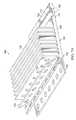
- FIG. 2illustrates one embodiment of a lighting assembly that may be used to light the billboard of FIG. 1 ;
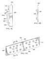
- FIGS. 3A and 3Billustrate one embodiment of a back panel that may be used in the lighting assembly of FIG. 2 ;
- FIG. 3Cillustrates one embodiment of the back panel of FIGS. 3A and 3B with a light panel and an optics panel that may also be used in the lighting assembly of FIG. 2 ;
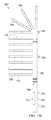
- FIGS. 4A and 4Billustrate one embodiment of a light panel that may be used with the lighting assembly of FIG. 2 ;
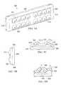
- FIGS. 5A , 5 B, 5 C and 5 Dillustrate one embodiment of an optics panel that may be used with the lighting assembly of FIG. 2 ;
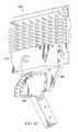
- FIGS. 6A-6Cillustrate a more detailed embodiment of the lighting assembly of FIG. 2 ;
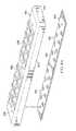
- FIGS. 7A and 7Billustrate an embodiment of a back panel that may be used with the lighting assembly of FIGS. 6A-6C ;
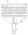
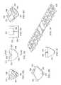
- FIG. 8Aillustrates an embodiment of an LED assembly and an optics panel that may be used with the lighting assembly of FIG. 6 ;
- FIGS. 8B-8Jillustrates embodiments of the optics panel of FIG. 8A and optical elements that may be used to form part of the optics panel;
- FIG. 9illustrates a more detailed embodiment of the lighting assembly of FIG. 2 .
- Billboardssuch as those commonly used for advertising in cities and along roads, often have a picture and/or text that must be externally illuminated to be visible in low-light conditions.
- new lighting devicessuch as the light emitting diode (LED)
- LEDlight emitting diode
- current lighting designshave limitations and improvements are needed.
- billboardsare used herein for purposes of example, it is understood that the present disclosure may be applied to lighting for any type of sign that is externally illuminated.
- the billboard 100includes a surface 102 onto which a picture and/or text may be painted, mounted, or otherwise affixed.
- the surface 102may be any size, such as a commonly used size having a width of forty-eight feet wide and a height of fourteen feet.
- the surface 102may be provided by placing a backing material on a frame 104 made of steel and/or other materials.
- the frame 104may be mounted on one or more support poles 106 , which may be considered part of the frame 104 or separate from the frame 104 .
- the billboard 100may include a walkway or other support structure 108 that enables the surface 102 to be more easily accessed.
- One or more lighting assemblies 110may be coupled to the walkway 108 (e.g., to a safety rail or to the walkway itself) and/or to another structural member of the billboard 100 to illuminate some or all of the surface 102 in low light conditions.
- the lighting assembly 110may be mounted at or near a top edge 112 of the billboard 100 , a bottom edge 114 of the billboard 100 , a right edge 116 of the billboard 100 , and/or a bottom edge 118 of the billboard 100 .
- the lighting assembly 110may be centered (e.g., located in approximately the center of the billboard 100 ) or off center as illustrated in FIG. 1A .
- a surface 120 of the lighting assembly 110may be parallel with respect to the surface 102 of the billboard 100 ( FIG. 1B ), may be perpendicular with respect to the surface 102 ( FIG. 1C ), or may be angled with respect to the surface 102 ( FIG. 1D ). It is understood that the lighting assembly 110 may be placed in many different orientations and locations relative to the billboard 100 and to one another, and the illustrated positions are only for purposes of example. Furthermore, it is understood that references to “top,” “bottom,” “left,” and “right” are used in the present disclosure for purposes of description and do not necessarily denote a fixed position. For example, the billboard 100 may be turned on end, and the referenced “top,” “bottom,” “left,” and “right” edges may still be readily identifiable although the “top” edge would be the “left” edge or the “right” edge.
- One problem with current lighting technologyis that it can be difficult to direct light only onto the surface 102 and even more difficult to do so evenly. This may be due partly to the placement of the lighting assembly 110 , as shown in FIGS. 1B-1D . As the lighting assembly 110 is off center relative to the surface 102 , light emitted from the lighting assembly 110 may not evenly strike the surface 102 .
- One problem with uneven illuminationis that certain parts of the surface 102 may be more brightly illuminated than other parts. This creates “hot spots” that may be undesirable. Attempting to evenly illuminate the surface 102 may cause light to be directed past the edges 112 , 114 , 116 , and 118 as attempts are made to balance out hot spots in particular areas. However, light that does not strike the surface 102 is wasted and may create problems (e.g., light pollution), as well as waste illumination that could be used for the surface 102 .
- the lighting assembly 200provides a more detailed embodiment of the lighting assembly 110 of FIG. 1 .
- the lighting assembly 200includes a back panel 202 , a light panel 204 (e.g., a printed circuit board (PCB)) having a plurality of LEDs (not shown) mounted thereon, and an optics panel 206 .
- a light panel 204e.g., a printed circuit board (PCB)
- PCBprinted circuit board
- optics panel 206As will be described below in more detailed examples, light from the LEDs of the light panel 204 may be directed by the optics panel 206 to illuminate the surface 102 of the billboard 100 of FIG. 1 .
- the back panel 202may be configured to serve as a supporting substrate for the light panel 204 and optics panel 206 , as well as to dissipate heat produced by the LEDs.
- any of the back panel 202 , light panel 204 , and optics panel 206may actually be two or more physical substrates rather than a single panel as illustrated in FIG. 2 . Furthermore, it is understood that there may be additional panels positioned behind the back panel 202 , in front of the optics panel 206 , and/or between the back panel 202 and light panel 204 and/or between the light panel 204 and optics panel 206 .
- the back panel 202is illustrated with a front surface 302 and a back surface 304 .
- the back panel 202includes a top edge 306 , a bottom edge 308 , a right edge 310 , and a left edge 312 .
- the panel 202may be formed of one or more thermally conductive materials (e.g., aluminum) and/or other materials.
- the front surface 302provides a mounting surface for the light panel 204 .
- the front surface 302 of the panel 202may include one or more protrusions 314 a and 314 b that are substantially parallel to the top edge 306 .
- the protrusions 314 a and 314 bmay be configured to protect the light panel 204 from moisture. Although only two protrusions 314 a and 314 b are illustrated, it is understood that a single protrusion may be provided or three or more protrusions may be provided. Furthermore, such protrusions may vary in length, shape (e.g., may have angled or curved surfaces), orientation, and/or location on the front surface 302 .
- a light panel 204 and an optical panel 206may be mounted under the protrusion 314 a ( FIG. 3C ).
- Moisture running down the front surface 302 in the direction of arrow 316may strike the protrusion 314 a and be directed away from the light panel 204 and optical panel 206 as shown by arrow 318 .
- moisturemay also be directed length down the protrusion 314 a .
- protrusion 314 amay serve as a gutter and aid in directing moisture away from a joint 320 where the optical panel 206 abuts the front surface 302 . This may be beneficial even when a moisture resistant compound is used to seal the joint 320 .
- each light panel 204there may be a protrusion positioned above each light panel 204 .
- the protrusion 314 amay be positioned directly above one light panel 204 and the protrusion 314 b may be positioned directly above another light panel 204 .
- the back surface 304may be configured to increase heat dissipation.
- the back surface 304may be configured with a heat sink provided by fins 322 a - 322 N, where N denotes a total number of fins.
- the fins 322 a - 322 Nincrease the surface area of the back surface 304 , thereby providing for additional heat dissipation to the surrounding air.
- the fins 322 a - 322 Nmay be formed as part of the panel 202 or may be otherwise coupled to the panel 202 (e.g., may be part of a discrete heat sink that is coupled to the back surface 304 ).
- Some or all of the fins 322 a - 322 Nmay be angled, as shown by fins 322 a and 322 b .
- holesmay be provided in some or all of the fins 322 a - 322 N to aid in air circulation.
- the holesmay cause a chimney effect in which heated air rises through the holes and is replaced by cooler air. This may be particularly effective in environments where natural air movement is limited.
- the light panel 204may include multiple PCBs 402 , although it is understood that any number of PCBs may be used based on design issues such as the amount of illumination needed, the amount of illumination provided by a single PCB 402 , the size of the surface 102 of the billboard 100 , and/or other factors.
- the PCB 402includes a front surface 404 , a back surface 406 , a top edge 408 , a bottom edge 410 , a right edge 412 , and a left edge 414 .
- the PCB 402may include one or more strings of LEDs 416 , with multiple LEDs 416 in a string.
- a stringmay include eight LEDs 416 and each PCB 402 may include two strings for a total of sixteen LEDs 416 .
- a light panel 204 having eight PCBs 402would include ninety-six LEDs 416 .
- the PCBs 404are shown as being substantially identical, they may be different in terms of size, shape, and other factors for a single light panel 204 .
- the LEDs 416are surface mounted, but it is understood that the LEDs 416 may be coupled to the panel 204 using through hole or another coupling process.
- the surface mounted configurationmay ensure that a maximum surface area of each LED 416 is in contact with the PCB 404 , which is in turn in contact with the back panel 202 responsible for heat dissipation.
- Each string of LEDsmay receive a constant current with the current divided evenly among the LEDs 416 .
- the optics panel 206may include multiple lens panels 500 , although it is understood that any number of lens panels may be used based on design issues such as the number, arrangement, and orientation of the LEDs 416 , the size of the surface 102 , and/or other factors. As shown in the present embodiment with a substantially rectangular cross-section that is configured for use with the PCB 402 of FIG.
- a single lens panel 500includes a front surface 502 , a back surface 504 , a top side 506 , a bottom side 508 , a right side 510 , and a left side 512 .
- the sides 506 , 508 , 510 , and 512may form a cavity into which the PCB 402 may fit, thereby providing protection for the PCB 402 from environmental conditions such as moisture.
- the lens panel 500may include a beveled or angled top side 506 and/or bottom side 508 as illustrated in FIG. 5B .
- the beveling/anglingmay aid in preventing moisture from reaching the PCB 402 under the lens panel 500 , as water will more readily flow from the area of the joint 320 ( FIG. 3C ) due to the angled surface than if the top side 506 was relatively flat.
- the lens panel 500may include multiple optical elements 514 .
- a single optical element 514may be provided for each LED 416 , a single optical element 514 may be provided for multiple LEDs 416 , and/or multiple optical elements 514 may be provided for a single LED 416 .
- the optical elements 514may be provided by a single multi-layer optical element system provided by the lens panel 500 .
- the optical elements 514are configured so that the light emitted from each LED 416 is projected onto the entire surface 102 of the billboard 100 .
- the entire surface 102would be illuminated at the level of illumination provided by the single LED 416 .
- the rectangular target area of the surface 102would be evenly illuminated by the LED 416 , while areas beyond the edges 112 , 114 , 116 , and 118 would receive no illumination at all or at least a minimal amount of illumination from the LED 416 . What is meant by “evenly” is that the illumination with a uniformity that achieves a 3:1 ratio of the average illumination to the minimum.
- the lensin such a manner, when all LEDs are operating, the light form the collective thereof will illuminate the surface at the 3:1 ratio. When one or more LEDs fail, the overall illumination decreases, but the uniformity maintains the same uniformity.
- the “surface”refers to the surface that is associated with a particular LED panel. It may be that an overall illuminated surface is segmented and multiple panels are provided, each associated with a particular segment.
- FIG. 5Cillustrates a detail of the lens assembly.
- Each of the diodes 416is mounted on the board 408 at a minimum distance.
- Overlying the board and LEDs 416is transparent lens substrate 520 .
- This substrate 520has a plurality of lens structures 522 , each associated with one of the LEDs 416 , such that each of the LEDs 416 has the light emitted therefrom directed outward towards the surface, each lens structure being substantially the same.
- the minimum distanceis designed such that overlapping light from adjacent LEDs does not create interference patters and result in dead spots on the surface.
- the lens structure 522is designed to create the 3:1 uniformity and also, the lens structure is designed to “direct” the light from an edge of the surface to cover the entire surface. This is shown by the angle of the light rays in FIG. 5C .
- the beveled edge 530will basically surround the PCB 408 , thus protecting it from moisture.
- the lens substrate 520is secured with screws (not shown).
- FIG. 5Dillustrates a detail of the lens structure 522 .
- This structureincludes an interior surface 524 and an exterior surface 526 that shapes and directs the light in the correct pattern.
- Thisis an acrylic material.
- the lighting assemblycan be disposed at an edge of the surface to illuminate the entire surface.
- each lighting assemblymay be powered by a separate power supply (not shown), and may be configured to illuminate the entire surface 102 .
- a separate power supplynot shown
- the remaining lighting assembly 110will still illuminate the entire surface 102 , although at a lesser intensity than when both lighting assemblies 110 are functioning.
- Thisprovides evenly distributed illumination when both lighting assemblies 110 are functioning correctly, and continues to provide evenly distributed illumination when one lighting assembly 110 malfunctions. Accordingly, the entire surface 102 of the billboard 100 may be illuminated even when an entire lighting assembly 110 has malfunctioned and is providing no illumination at all due to the redundancy provided by configuration of the lighting assemblies 110 .
- each LED 416 of a single lighting assembly 110may be configured via the optical elements 514 to illuminate the entire surface 102 .
- the remaining LEDs 416will still illuminate the entire surface 102 , although at a lesser intensity than when the failed LEDs 416 are functioning.
- Thisprovides evenly distributed illumination when all LEDs 416 are functioning correctly, and continues to provide evenly distributed illumination when one or more LEDs are malfunctioning. Accordingly, the billboard 100 may be illuminated even when multiple LEDs 416 have malfunctioned and are providing no illumination at all due to the redundancy provided by configuration of the lighting assemblies 110 .
- some embodimentsmay direct substantially all illumination from a lighting assembly 110 evenly across the surface 102 while some illumination is not evenly distributed.
- substantially all LEDs 416may be directed to each evenly illuminate the surface 102 with the exception of a relatively small number of LEDs 416 .
- the illumination provided by the remaining LED or LEDs 416may be directed to one or more portions of the surface 102 . If done properly, this may be accomplished while minimizing any noticeable unevenness in the overall illumination, even if one of the remaining LEDs 416 malfunctions.
- the lighting assembly 110may be configured to direct the illumination provided by one LED 416 to only the left half of the surface 102 , while directing the illumination from another LED 416 to only the right half of the surface 102 . The loss of one of these two LEDs may not noticeably impact the illumination of the surface 102 . It is understood that such variations are within the scope of this disclosure.
- the optics panel 206may be configured specifically for the light panel 204 and the surface 102 .
- the lens panel 500 of FIG. 5may be specifically designed for use with the PCB 402 of FIG. 4 . This design may be based on the particular layout of the PCB 402 (e.g., the number and arrangement of the LEDs 416 ), the amount of illumination provided by the LEDs 416 , the size of the surface 102 , the distance between the lens panel 500 and the surface 102 , the angle at which the lens panel 500 is mounted relative to the surface 102 (e.g., FIGS.
- the lighting assembly 600includes a back panel 602 , a light panel formed by multiple LED assemblies (denoted by reference number 800 in FIG. 8A ), and an optics panel formed by multiple lens panels 604 . Accordingly, as described previously, the light panel 204 in the current example is represented by multiple LED assemblies 800 and the optics panel 206 is represented by multiple lens panels 604 . In the present embodiment, the lighting assembly 600 includes four LED assemblies 800 and four lens panels 604 .
- the present embodimentuses multiple threaded fasteners 605 (e.g., screws) that extend through the lens panels and the LED assemblies and engage threaded holes in the back panel 602 .
- the lighting assembly 600is also illustrated with a mounting plate 606 that couples to the back panel 602 and to an adjustable mounting bracket 608 .
- the adjustable mounting bracket 608may be used to couple the lighting assembly 600 to a portion of the billboard 100 ( FIG. 1 ) and/or to another support member.
- a power supply enclosure 610may be coupled to the mounting plate 606 and configured contain a power supply (not shown) capable of supplying power to LEDs of the LED assemblies 800 . It is noted that separating the power supply from the back panel 602 may aid in heat dissipation by the back panel 602 as it does not have to dissipate heat from the power supply to the same extent as if the power supply was mounted directly to the back panel 602 .
- the location of the power supplymay also be beneficial as snow not melted by the heat produced by the LED may be melted by heat produced by the power supply. This may aid in reducing snow buildup on the LEDs.
- a front surface 700includes multiple protrusions 702 that may be configured to protect the light panels (not shown) against moisture as previously described.
- the front surface 700may include additional protrusions 704 .
- a back surface 706includes multiple fins 708 that form a heat sink to aid in the dissipation of heat from the back panel 602 .
- the fins 708are substantially rectangular in shape.
- the back panel 602is extruded and the fins 708 run parallel to the top edge with a longitudinal axis of each fin 708 being substantially parallel to a longitudinal axis of the back panel 602 .
- Forming the fins 708 in a vertical manneris possible, but may increase the cost of the back panel 602 due to the extrusion process.
- the fins 708may be substantially perpendicular to the back surface 706 , and/or may be angled. In the present example, the fins 708 are angled such that near the top of the back panel 702 , the fins 708 are angled towards the top.
- holes 710may be present in some or all of the fins 708 (marked but not actually visible in the side view of FIG. 7B ) to provide paths for the heat to rise vertically in spite of the orientation of the fins 708 .
- the holes 710may create a chimney effect that increases air flow across the fins 708 and aids in the cooling process.
- some or all of the fins 708may be angled such that heat is not trapped.
- the back surface 706may also include a groove 712 that is configured to receive a tongue of the mounting plate 606 in a tongue-in-groove manner.
- FIGS. 8A-8Jembodiments of a single LED assembly 800 and a single lens panel 604 that may be used with the lighting assembly 600 are illustrated. As shown, the single LED assembly 800 and the single optics panel 604 may be configured for use together.
- the LED assembly 800includes a substrate 802 (e.g., a PCB) onto which are mounted multiple LEDs 804 .
- the LED assembly 800includes two strings of eight LEDs 804 each for a total of sixteen LEDs 804 . It is understood that this is merely an example, and there may be more or fewer LEDs 804 on the light panel 800 , and the LEDs 804 may be arranged in many different ways on the substrate 802 .
- the optics panel 604may include optical elements 806 arranged on an upper surface 808 of the optics panel 604 .
- the optics panel 604may further include sides 810 , 812 , 814 , and 816 that are configured to fit around the edge of the substrate 802 of the light panel 800 .
- the bottom edge of each side 810 , 812 , 814 , and 816abuts the front surface 700 of the back panel 602 and may be sealed to the front surface 700 using a moisture resistant sealant.
- a single optical element 806may include multiple lens elements designed to distribute the illumination provided by a single LED 804 across a surface such as the surface 102 of FIG. 1 .
- a first lens element 820may be positioned proximate to the LED 804 , and additional lens elements 822 , 824 , and 826 may be positioned above the lens element 820 .
- Multiple optical elements 806may be combined and formed as a single optics panel 604 that is configured to operate with the LED assembly 800 .
- FIG. 9another embodiment of a lighting assembly 900 is illustrated that provides a more detailed embodiment of the lighting assembly 200 of FIG. 2 .
- the lighting assembly 900is similar to the lighting assembly 600 of FIG. 6 , but includes six LED assemblies rather than the four six LED assemblies of the lighting assembly 600 . It is understood that the lighting assembly 900 may require a larger power supply than the lighting assembly 600 (e.g., a one hundred and fifty watt power supply instead of a one hundred and twenty watt power supply).
Landscapes
- Engineering & Computer Science (AREA)
- General Engineering & Computer Science (AREA)
- Physics & Mathematics (AREA)
- Microelectronics & Electronic Packaging (AREA)
- Optics & Photonics (AREA)
- General Physics & Mathematics (AREA)
- Theoretical Computer Science (AREA)
- Illuminated Signs And Luminous Advertising (AREA)
- Devices For Indicating Variable Information By Combining Individual Elements (AREA)
- Non-Portable Lighting Devices Or Systems Thereof (AREA)
Abstract
Description
Claims (33)
Priority Applications (2)
| Application Number | Priority Date | Filing Date | Title |
|---|---|---|---|
| US13/836,612US8870410B2 (en) | 2012-07-30 | 2013-03-15 | Optical panel for LED light source |
| US14/137,343US8870413B2 (en) | 2012-07-30 | 2013-12-20 | Optical panel for LED light source |
Applications Claiming Priority (2)
| Application Number | Priority Date | Filing Date | Title |
|---|---|---|---|
| US201261677340P | 2012-07-30 | 2012-07-30 | |
| US13/836,612US8870410B2 (en) | 2012-07-30 | 2013-03-15 | Optical panel for LED light source |
Related Child Applications (1)
| Application Number | Title | Priority Date | Filing Date |
|---|---|---|---|
| US14/137,343ContinuationUS8870413B2 (en) | 2012-07-30 | 2013-12-20 | Optical panel for LED light source |
Publications (2)
| Publication Number | Publication Date |
|---|---|
| US20140029253A1 US20140029253A1 (en) | 2014-01-30 |
| US8870410B2true US8870410B2 (en) | 2014-10-28 |
Family
ID=49994720
Family Applications (2)
| Application Number | Title | Priority Date | Filing Date |
|---|---|---|---|
| US13/836,612Expired - Fee RelatedUS8870410B2 (en) | 2012-07-30 | 2013-03-15 | Optical panel for LED light source |
| US14/137,343Expired - Fee RelatedUS8870413B2 (en) | 2012-07-30 | 2013-12-20 | Optical panel for LED light source |
Family Applications After (1)
| Application Number | Title | Priority Date | Filing Date |
|---|---|---|---|
| US14/137,343Expired - Fee RelatedUS8870413B2 (en) | 2012-07-30 | 2013-12-20 | Optical panel for LED light source |
Country Status (1)
| Country | Link |
|---|---|
| US (2) | US8870410B2 (en) |
Cited By (4)
| Publication number | Priority date | Publication date | Assignee | Title |
|---|---|---|---|---|
| US9212803B2 (en) | 2012-07-30 | 2015-12-15 | Ultravision Technologies, Llc | LED light assembly with three-part lens |
| US9651203B2 (en) | 2012-12-14 | 2017-05-16 | Osram Oled Gmbh | Light panel system |
| US11300721B2 (en) | 2020-07-10 | 2022-04-12 | Abl Ip Holding Llc | Lighting apparatus having an oblong optic corresponding to multiple light sources |
| US11536438B2 (en) | 2020-10-26 | 2022-12-27 | Abl Ip Holding Llc | Lighting apparatus having an optic with a centered light source and an off-center light source |
Families Citing this family (4)
| Publication number | Priority date | Publication date | Assignee | Title |
|---|---|---|---|---|
| JP6467313B2 (en)* | 2015-08-04 | 2019-02-13 | 三協立山株式会社 | Sign illuminator |
| US11350773B2 (en)* | 2018-06-25 | 2022-06-07 | Signify Holding B.V. | Lighting system for projecting transverse light patches |
| PL3810982T3 (en)* | 2018-06-25 | 2025-03-24 | Signify Holding B.V. | LIGHTING DEVICE AND LIGHTING SYSTEM |
| US11125421B2 (en)* | 2019-03-29 | 2021-09-21 | Walter R. Tucker Enterprises, Ltd. | Clamping work light |
Citations (89)
| Publication number | Priority date | Publication date | Assignee | Title |
|---|---|---|---|---|
| US4235285A (en) | 1979-10-29 | 1980-11-25 | Aavid Engineering, Inc. | Self-fastened heat sinks |
| US4679118A (en) | 1984-08-07 | 1987-07-07 | Aavid Engineering, Inc. | Electronic chip-carrier heat sinks |
| US5036248A (en) | 1989-03-31 | 1991-07-30 | Ledstar Inc. | Light emitting diode clusters for display signs |
| US5083194A (en) | 1990-01-16 | 1992-01-21 | Cray Research, Inc. | Air jet impingement on miniature pin-fin heat sinks for cooling electronic components |
| US5329426A (en) | 1993-03-22 | 1994-07-12 | Digital Equipment Corporation | Clip-on heat sink |
| US5384940A (en) | 1992-02-28 | 1995-01-31 | Aavid Engineering, Inc. | Self-locking heat sinks for surface mount devices |
| US5818640A (en) | 1994-08-01 | 1998-10-06 | Minnesota Mining And Manufacturing Company | Sign illumination system and method |
| US5857767A (en) | 1996-09-23 | 1999-01-12 | Relume Corporation | Thermal management system for L.E.D. arrays |
| US5896093A (en) | 1998-04-03 | 1999-04-20 | Sjobom; Fritz C. | L.E.D. light assembly for traffic arrowboards |
| US6045240A (en) | 1996-06-27 | 2000-04-04 | Relume Corporation | LED lamp assembly with means to conduct heat away from the LEDS |
| US6274924B1 (en) | 1998-11-05 | 2001-08-14 | Lumileds Lighting, U.S. Llc | Surface mountable LED package |
| US6364507B1 (en) | 2000-05-01 | 2002-04-02 | Formosa Industrial Computing Inc. | Waterproof LED display |
| US6428189B1 (en) | 2000-03-31 | 2002-08-06 | Relume Corporation | L.E.D. thermal management |
| US6517218B2 (en) | 2000-03-31 | 2003-02-11 | Relume Corporation | LED integrated heat sink |
| US20040004827A1 (en)* | 2002-07-08 | 2004-01-08 | Guest Christopher William | Light devices using light emitting diodes |
| US6799864B2 (en) | 2001-05-26 | 2004-10-05 | Gelcore Llc | High power LED power pack for spot module illumination |
| US20050047170A1 (en) | 2003-09-02 | 2005-03-03 | Guide Corporation (A Delaware Corporation) | LED heat sink for use with standard socket hole |
| US6864513B2 (en) | 2003-05-07 | 2005-03-08 | Kaylu Industrial Corporation | Light emitting diode bulb having high heat dissipating efficiency |
| US7048400B2 (en) | 2001-03-22 | 2006-05-23 | Lumimove, Inc. | Integrated illumination system |
| US20060146531A1 (en) | 2004-12-30 | 2006-07-06 | Ann Reo | Linear lighting apparatus with improved heat dissipation |
| WO2006126123A1 (en) | 2005-05-25 | 2006-11-30 | Koninklijke Philips Electronics N.V. | Illumination system with leds |
| US7144135B2 (en) | 2003-11-26 | 2006-12-05 | Philips Lumileds Lighting Company, Llc | LED lamp heat sink |
| US7159997B2 (en) | 2004-12-30 | 2007-01-09 | Lo Lighting | Linear lighting apparatus with increased light-transmission efficiency |
| US20080080179A1 (en) | 2006-10-03 | 2008-04-03 | Sgm Technology For Lighting S.P.A. | LED floodlight structure |
| US20080084701A1 (en) | 2006-09-21 | 2008-04-10 | Led Lighting Fixtures, Inc. | Lighting assemblies, methods of installing same, and methods of replacing lights |
| US7375381B2 (en) | 2001-08-09 | 2008-05-20 | Matsushita Electric Industrial Co., Ltd. | LED illumination apparatus and card-type LED illumination source |
| US7396146B2 (en) | 2006-08-09 | 2008-07-08 | Augux Co., Ltd. | Heat dissipating LED signal lamp source structure |
| US20080180014A1 (en) | 2007-01-29 | 2008-07-31 | Tennrich International Corp. | LED heat sink |
| US7434964B1 (en) | 2007-07-12 | 2008-10-14 | Fu Zhun Precision Industry (Shen Zhen) Co., Ltd. | LED lamp with a heat sink assembly |
| US7458706B1 (en) | 2007-11-28 | 2008-12-02 | Fu Zhun Precision Industry (Shen Zhen) Co., Ltd. | LED lamp with a heat sink |
| US7513653B1 (en) | 2007-12-12 | 2009-04-07 | Fu Zhun Precision Industry (Shen Zhen) Co., Ltd. | LED lamp having heat sink |
| US20090097265A1 (en) | 2007-10-11 | 2009-04-16 | Foxsemicon Integrated Technology, Inc. | Light source module |
| US7549777B2 (en) | 2005-05-20 | 2009-06-23 | Agon-Tech. Corporation | Waterproof heat dissipating structure for electronic signboard |
| US20090180281A1 (en) | 2008-01-16 | 2009-07-16 | Ahland Iii Walter W | Submersible High Illumination LED Light Source |
| US20090256459A1 (en) | 2008-04-11 | 2009-10-15 | Foxconn Technology Co., Ltd. | Led illuminating device and light engine thereof |
| US20090303711A1 (en) | 2008-06-06 | 2009-12-10 | Servicios Condumex S.A. De C.V. | Electronic luminaire based on light emitting diodes |
| US7654684B1 (en) | 2005-04-01 | 2010-02-02 | Wight Robert M | Solar-rechargeable light |
| US20100046225A1 (en) | 2008-08-19 | 2010-02-25 | Fu Zhun Precision Industry (Shen Zhen) Co., Ltd. | Led lamp |
| US7686469B2 (en) | 2006-09-30 | 2010-03-30 | Ruud Lighting, Inc. | LED lighting fixture |
| US20100085774A1 (en) | 2007-04-25 | 2010-04-08 | Hyu Wan Park | Lighting device using light guide plate |
| US7748863B1 (en) | 2005-09-01 | 2010-07-06 | Jeffrey T. Holman | Solar light apparatus and system |
| US20100232155A1 (en) | 2009-03-12 | 2010-09-16 | Pei-Choa Wang | Combination structure of led lighting device |
| US20100296267A1 (en) | 2009-05-25 | 2010-11-25 | POWER LIGHT Tech. Co., Ltd. | Lamp structure for illuminating and displaying |
| US7857483B2 (en) | 2008-05-13 | 2010-12-28 | Honeywell International Inc. | Systems and methods for a high-intensity light emitting diode floodlight |
| US7866851B2 (en) | 2008-06-09 | 2011-01-11 | Tong-Lung Chang | LED heat sink |
| US20110031887A1 (en) | 2009-05-28 | 2011-02-10 | Stoll Arnold | Led lighting system |
| US7896522B2 (en)* | 2008-02-20 | 2011-03-01 | Formetco, Inc. | Frontal illumination of a surface using LED lighting |
| US7905634B2 (en) | 2008-06-16 | 2011-03-15 | Light Prescriptions Innovators, Llc | Multi-reflector LED light source with cylindrical heat sink |
| US7952262B2 (en) | 2006-09-30 | 2011-05-31 | Ruud Lighting, Inc. | Modular LED unit incorporating interconnected heat sinks configured to mount and hold adjacent LED modules |
| US20110149548A1 (en) | 2009-12-22 | 2011-06-23 | Intematix Corporation | Light emitting diode based linear lamps |
| US20110170283A1 (en) | 2005-05-09 | 2011-07-14 | Sze Keun Chan | Solar Powered Led Street Lamp With Automatic Light Control |
| US20110242816A1 (en) | 2010-04-02 | 2011-10-06 | GE Lighting Solutions, LLC | Lightweight heat sinks and led lamps employing same |
| US8035119B2 (en) | 2006-10-03 | 2011-10-11 | Avago Technologies General IP Pte, Ltd. | System and method for light source with discontinuity-containing diffusant |
| US8052303B2 (en) | 2006-09-12 | 2011-11-08 | Huizhou Light Engine Ltd. | Integrally formed single piece light emitting diode light wire and uses thereof |
| US8056614B2 (en) | 2007-06-08 | 2011-11-15 | Ama Precision Inc. | Heat sink and modular heat sink |
| US20110278633A1 (en) | 2010-05-11 | 2011-11-17 | Scott Allen Clifford | LED Light Bulb With Integrated Heat Sink |
| US20110280003A1 (en) | 2010-05-14 | 2011-11-17 | Chih-Hua Hsu | Backlight module and display device with two-sided light emitting structure |
| US8092049B2 (en) | 2008-04-04 | 2012-01-10 | Ruud Lighting, Inc. | LED light fixture |
| US20120080699A1 (en) | 2010-09-30 | 2012-04-05 | GE Lighting Solutions, LLC | Lightweight heat sinks and led lamps employing same |
| US8192048B2 (en) | 2009-04-22 | 2012-06-05 | 3M Innovative Properties Company | Lighting assemblies and systems |
| US8201970B2 (en) | 2009-10-15 | 2012-06-19 | Fu Zhun Precision Industry (Shen Zhen) Co., Ltd. | LED lamp having improved waterproof performance |
| US20120163005A1 (en) | 2010-12-28 | 2012-06-28 | Keeper Technology Co., Ltd. | Mounting Device for LED Lamp |
| US8235553B2 (en) | 2009-02-16 | 2012-08-07 | Mitsubishi Electric Corporation | Lighting device for a headlamp light source |
| US20120201022A1 (en) | 2011-02-07 | 2012-08-09 | Cree, Inc. | Solid state lighting device with elongated heatsink |
| US8246219B2 (en) | 2008-11-04 | 2012-08-21 | Advanced Optoelectronic Technology, Inc. | Light emitting diode light module and optical engine thereof |
| US8267551B2 (en) | 2010-10-08 | 2012-09-18 | Chiu-Min Lin | LED road light |
| US8273158B2 (en) | 2010-11-29 | 2012-09-25 | General Electric Company | Mist eliminator, moisture removal system, and method of removing water particles from inlet air |
| US20120250321A1 (en) | 2011-04-01 | 2012-10-04 | Patrick Stephen Blincoe | Light-emitting diode (led) floodlight |
| US8310158B2 (en) | 2009-09-23 | 2012-11-13 | Ecofit Lighting, LLC | LED light engine apparatus |
| US8308331B2 (en) | 2005-06-14 | 2012-11-13 | Cree, Inc. | LED backlighting for displays |
| US8330387B2 (en) | 2007-05-02 | 2012-12-11 | Koninklijke Philips Electronics N.V. | Solid-state lighting device |
| US8338841B2 (en) | 2010-08-27 | 2012-12-25 | Quarkstar Llc | Solid state light strips containing LED dies in series |
| US8348461B2 (en) | 2009-10-30 | 2013-01-08 | Ruud Lighting, Inc. | LED apparatus and method for accurate lens alignment |
| US8360613B2 (en) | 2009-07-15 | 2013-01-29 | Aphos Lighting Llc | Light feature |
| US8376585B2 (en) | 2008-10-28 | 2013-02-19 | Raymond A. Noeth | Energy efficient illumination apparatus and method for illuminating surfaces |
| US20130057861A1 (en) | 2011-09-07 | 2013-03-07 | Toshihiro Ishii | Moisture sensor, moisture detector, and image forming apparatus |
| US20130063970A1 (en) | 2010-05-14 | 2013-03-14 | Wan Ho Oh | Multi-sectioned, billboard-mounted light-emitting device |
| US8454194B2 (en) | 2010-10-20 | 2013-06-04 | Foxconn Technology Co., Ltd. | Light emitting diode lamp |
| US8454215B2 (en) | 2009-07-15 | 2013-06-04 | Ringdale, Inc. | Method and LED apparatus for billboard lighting |
| US8465178B2 (en) | 2010-09-07 | 2013-06-18 | Cree, Inc. | LED lighting fixture |
| US20130193850A1 (en) | 2012-01-26 | 2013-08-01 | Randy Demuynck | Remote thermal compensation assembly |
| US8547023B2 (en) | 2010-06-28 | 2013-10-01 | Rui Teng Opto Technology Co., Ltd. | LED light source module |
| US20130270585A1 (en) | 2011-12-28 | 2013-10-17 | Ledengin, Inc. | System and methods for warm white led light source |
| US8567987B2 (en) | 2009-07-21 | 2013-10-29 | Cooper Technologies Company | Interfacing a light emitting diode (LED) module to a heat sink assembly, a light reflector and electrical circuits |
| US8577434B2 (en) | 2007-12-27 | 2013-11-05 | Covidien Lp | Coaxial LED light sources |
| US8602599B2 (en) | 2010-05-11 | 2013-12-10 | Dialight Corporation | Hazardous location lighting fixture with a housing including heatsink fins |
| US8610357B2 (en) | 2009-05-28 | 2013-12-17 | Zon Led, Llc | LED assembly for a signage illumination |
| US8628217B2 (en) | 2011-11-12 | 2014-01-14 | Bridgelux, Inc. | Low profile heat sink with attached LED light source |
| US20140029259A1 (en) | 2012-07-30 | 2014-01-30 | Ultravision Holdings, Llc | Heat sink for led light source |
- 2013
- 2013-03-15USUS13/836,612patent/US8870410B2/ennot_activeExpired - Fee Related
- 2013-12-20USUS14/137,343patent/US8870413B2/ennot_activeExpired - Fee Related
Patent Citations (91)
| Publication number | Priority date | Publication date | Assignee | Title |
|---|---|---|---|---|
| US4235285A (en) | 1979-10-29 | 1980-11-25 | Aavid Engineering, Inc. | Self-fastened heat sinks |
| US4679118A (en) | 1984-08-07 | 1987-07-07 | Aavid Engineering, Inc. | Electronic chip-carrier heat sinks |
| US5036248A (en) | 1989-03-31 | 1991-07-30 | Ledstar Inc. | Light emitting diode clusters for display signs |
| US5083194A (en) | 1990-01-16 | 1992-01-21 | Cray Research, Inc. | Air jet impingement on miniature pin-fin heat sinks for cooling electronic components |
| US5384940A (en) | 1992-02-28 | 1995-01-31 | Aavid Engineering, Inc. | Self-locking heat sinks for surface mount devices |
| US5329426A (en) | 1993-03-22 | 1994-07-12 | Digital Equipment Corporation | Clip-on heat sink |
| US5818640A (en) | 1994-08-01 | 1998-10-06 | Minnesota Mining And Manufacturing Company | Sign illumination system and method |
| US6045240A (en) | 1996-06-27 | 2000-04-04 | Relume Corporation | LED lamp assembly with means to conduct heat away from the LEDS |
| US5857767A (en) | 1996-09-23 | 1999-01-12 | Relume Corporation | Thermal management system for L.E.D. arrays |
| US5896093A (en) | 1998-04-03 | 1999-04-20 | Sjobom; Fritz C. | L.E.D. light assembly for traffic arrowboards |
| US6274924B1 (en) | 1998-11-05 | 2001-08-14 | Lumileds Lighting, U.S. Llc | Surface mountable LED package |
| US6428189B1 (en) | 2000-03-31 | 2002-08-06 | Relume Corporation | L.E.D. thermal management |
| US6517218B2 (en) | 2000-03-31 | 2003-02-11 | Relume Corporation | LED integrated heat sink |
| US6364507B1 (en) | 2000-05-01 | 2002-04-02 | Formosa Industrial Computing Inc. | Waterproof LED display |
| US7048400B2 (en) | 2001-03-22 | 2006-05-23 | Lumimove, Inc. | Integrated illumination system |
| US6799864B2 (en) | 2001-05-26 | 2004-10-05 | Gelcore Llc | High power LED power pack for spot module illumination |
| US7375381B2 (en) | 2001-08-09 | 2008-05-20 | Matsushita Electric Industrial Co., Ltd. | LED illumination apparatus and card-type LED illumination source |
| US20040004827A1 (en)* | 2002-07-08 | 2004-01-08 | Guest Christopher William | Light devices using light emitting diodes |
| US6864513B2 (en) | 2003-05-07 | 2005-03-08 | Kaylu Industrial Corporation | Light emitting diode bulb having high heat dissipating efficiency |
| US20050047170A1 (en) | 2003-09-02 | 2005-03-03 | Guide Corporation (A Delaware Corporation) | LED heat sink for use with standard socket hole |
| US7144135B2 (en) | 2003-11-26 | 2006-12-05 | Philips Lumileds Lighting Company, Llc | LED lamp heat sink |
| US20060146531A1 (en) | 2004-12-30 | 2006-07-06 | Ann Reo | Linear lighting apparatus with improved heat dissipation |
| US7159997B2 (en) | 2004-12-30 | 2007-01-09 | Lo Lighting | Linear lighting apparatus with increased light-transmission efficiency |
| US7654684B1 (en) | 2005-04-01 | 2010-02-02 | Wight Robert M | Solar-rechargeable light |
| US20110170283A1 (en) | 2005-05-09 | 2011-07-14 | Sze Keun Chan | Solar Powered Led Street Lamp With Automatic Light Control |
| US7549777B2 (en) | 2005-05-20 | 2009-06-23 | Agon-Tech. Corporation | Waterproof heat dissipating structure for electronic signboard |
| WO2006126123A1 (en) | 2005-05-25 | 2006-11-30 | Koninklijke Philips Electronics N.V. | Illumination system with leds |
| US8308331B2 (en) | 2005-06-14 | 2012-11-13 | Cree, Inc. | LED backlighting for displays |
| US7748863B1 (en) | 2005-09-01 | 2010-07-06 | Jeffrey T. Holman | Solar light apparatus and system |
| US7396146B2 (en) | 2006-08-09 | 2008-07-08 | Augux Co., Ltd. | Heat dissipating LED signal lamp source structure |
| US8052303B2 (en) | 2006-09-12 | 2011-11-08 | Huizhou Light Engine Ltd. | Integrally formed single piece light emitting diode light wire and uses thereof |
| US20080084701A1 (en) | 2006-09-21 | 2008-04-10 | Led Lighting Fixtures, Inc. | Lighting assemblies, methods of installing same, and methods of replacing lights |
| US7952262B2 (en) | 2006-09-30 | 2011-05-31 | Ruud Lighting, Inc. | Modular LED unit incorporating interconnected heat sinks configured to mount and hold adjacent LED modules |
| US7686469B2 (en) | 2006-09-30 | 2010-03-30 | Ruud Lighting, Inc. | LED lighting fixture |
| US20080080179A1 (en) | 2006-10-03 | 2008-04-03 | Sgm Technology For Lighting S.P.A. | LED floodlight structure |
| US8035119B2 (en) | 2006-10-03 | 2011-10-11 | Avago Technologies General IP Pte, Ltd. | System and method for light source with discontinuity-containing diffusant |
| US20080180014A1 (en) | 2007-01-29 | 2008-07-31 | Tennrich International Corp. | LED heat sink |
| US20100085774A1 (en) | 2007-04-25 | 2010-04-08 | Hyu Wan Park | Lighting device using light guide plate |
| US8330387B2 (en) | 2007-05-02 | 2012-12-11 | Koninklijke Philips Electronics N.V. | Solid-state lighting device |
| US8056614B2 (en) | 2007-06-08 | 2011-11-15 | Ama Precision Inc. | Heat sink and modular heat sink |
| US7434964B1 (en) | 2007-07-12 | 2008-10-14 | Fu Zhun Precision Industry (Shen Zhen) Co., Ltd. | LED lamp with a heat sink assembly |
| US20090097265A1 (en) | 2007-10-11 | 2009-04-16 | Foxsemicon Integrated Technology, Inc. | Light source module |
| US7458706B1 (en) | 2007-11-28 | 2008-12-02 | Fu Zhun Precision Industry (Shen Zhen) Co., Ltd. | LED lamp with a heat sink |
| US7513653B1 (en) | 2007-12-12 | 2009-04-07 | Fu Zhun Precision Industry (Shen Zhen) Co., Ltd. | LED lamp having heat sink |
| US8577434B2 (en) | 2007-12-27 | 2013-11-05 | Covidien Lp | Coaxial LED light sources |
| US20090180281A1 (en) | 2008-01-16 | 2009-07-16 | Ahland Iii Walter W | Submersible High Illumination LED Light Source |
| US7896522B2 (en)* | 2008-02-20 | 2011-03-01 | Formetco, Inc. | Frontal illumination of a surface using LED lighting |
| US8092049B2 (en) | 2008-04-04 | 2012-01-10 | Ruud Lighting, Inc. | LED light fixture |
| US20090256459A1 (en) | 2008-04-11 | 2009-10-15 | Foxconn Technology Co., Ltd. | Led illuminating device and light engine thereof |
| US7857483B2 (en) | 2008-05-13 | 2010-12-28 | Honeywell International Inc. | Systems and methods for a high-intensity light emitting diode floodlight |
| US20090303711A1 (en) | 2008-06-06 | 2009-12-10 | Servicios Condumex S.A. De C.V. | Electronic luminaire based on light emitting diodes |
| US7866851B2 (en) | 2008-06-09 | 2011-01-11 | Tong-Lung Chang | LED heat sink |
| US7905634B2 (en) | 2008-06-16 | 2011-03-15 | Light Prescriptions Innovators, Llc | Multi-reflector LED light source with cylindrical heat sink |
| US20100046225A1 (en) | 2008-08-19 | 2010-02-25 | Fu Zhun Precision Industry (Shen Zhen) Co., Ltd. | Led lamp |
| US8376585B2 (en) | 2008-10-28 | 2013-02-19 | Raymond A. Noeth | Energy efficient illumination apparatus and method for illuminating surfaces |
| US8246219B2 (en) | 2008-11-04 | 2012-08-21 | Advanced Optoelectronic Technology, Inc. | Light emitting diode light module and optical engine thereof |
| US8235553B2 (en) | 2009-02-16 | 2012-08-07 | Mitsubishi Electric Corporation | Lighting device for a headlamp light source |
| US20100232155A1 (en) | 2009-03-12 | 2010-09-16 | Pei-Choa Wang | Combination structure of led lighting device |
| US8192048B2 (en) | 2009-04-22 | 2012-06-05 | 3M Innovative Properties Company | Lighting assemblies and systems |
| US20100296267A1 (en) | 2009-05-25 | 2010-11-25 | POWER LIGHT Tech. Co., Ltd. | Lamp structure for illuminating and displaying |
| US8610357B2 (en) | 2009-05-28 | 2013-12-17 | Zon Led, Llc | LED assembly for a signage illumination |
| US20110031887A1 (en) | 2009-05-28 | 2011-02-10 | Stoll Arnold | Led lighting system |
| US8454215B2 (en) | 2009-07-15 | 2013-06-04 | Ringdale, Inc. | Method and LED apparatus for billboard lighting |
| US8360613B2 (en) | 2009-07-15 | 2013-01-29 | Aphos Lighting Llc | Light feature |
| US8567987B2 (en) | 2009-07-21 | 2013-10-29 | Cooper Technologies Company | Interfacing a light emitting diode (LED) module to a heat sink assembly, a light reflector and electrical circuits |
| US8310158B2 (en) | 2009-09-23 | 2012-11-13 | Ecofit Lighting, LLC | LED light engine apparatus |
| US8201970B2 (en) | 2009-10-15 | 2012-06-19 | Fu Zhun Precision Industry (Shen Zhen) Co., Ltd. | LED lamp having improved waterproof performance |
| US8348461B2 (en) | 2009-10-30 | 2013-01-08 | Ruud Lighting, Inc. | LED apparatus and method for accurate lens alignment |
| US20110149548A1 (en) | 2009-12-22 | 2011-06-23 | Intematix Corporation | Light emitting diode based linear lamps |
| US20110242816A1 (en) | 2010-04-02 | 2011-10-06 | GE Lighting Solutions, LLC | Lightweight heat sinks and led lamps employing same |
| EP2553331A1 (en) | 2010-04-02 | 2013-02-06 | GE Lighting Solutions, LLC | Lightweight heat sinks and led lamps employing same |
| US20110278633A1 (en) | 2010-05-11 | 2011-11-17 | Scott Allen Clifford | LED Light Bulb With Integrated Heat Sink |
| US8602599B2 (en) | 2010-05-11 | 2013-12-10 | Dialight Corporation | Hazardous location lighting fixture with a housing including heatsink fins |
| US20110280003A1 (en) | 2010-05-14 | 2011-11-17 | Chih-Hua Hsu | Backlight module and display device with two-sided light emitting structure |
| US20130063970A1 (en) | 2010-05-14 | 2013-03-14 | Wan Ho Oh | Multi-sectioned, billboard-mounted light-emitting device |
| US8547023B2 (en) | 2010-06-28 | 2013-10-01 | Rui Teng Opto Technology Co., Ltd. | LED light source module |
| US8338841B2 (en) | 2010-08-27 | 2012-12-25 | Quarkstar Llc | Solid state light strips containing LED dies in series |
| US8465178B2 (en) | 2010-09-07 | 2013-06-18 | Cree, Inc. | LED lighting fixture |
| US20120080699A1 (en) | 2010-09-30 | 2012-04-05 | GE Lighting Solutions, LLC | Lightweight heat sinks and led lamps employing same |
| EP2622267A1 (en) | 2010-09-30 | 2013-08-07 | GE Lighting Solutions, LLC | Lightweight heat sinks and led lamps employing same |
| US8267551B2 (en) | 2010-10-08 | 2012-09-18 | Chiu-Min Lin | LED road light |
| US8454194B2 (en) | 2010-10-20 | 2013-06-04 | Foxconn Technology Co., Ltd. | Light emitting diode lamp |
| US8273158B2 (en) | 2010-11-29 | 2012-09-25 | General Electric Company | Mist eliminator, moisture removal system, and method of removing water particles from inlet air |
| US20120163005A1 (en) | 2010-12-28 | 2012-06-28 | Keeper Technology Co., Ltd. | Mounting Device for LED Lamp |
| US20120201022A1 (en) | 2011-02-07 | 2012-08-09 | Cree, Inc. | Solid state lighting device with elongated heatsink |
| US20120250321A1 (en) | 2011-04-01 | 2012-10-04 | Patrick Stephen Blincoe | Light-emitting diode (led) floodlight |
| US20130057861A1 (en) | 2011-09-07 | 2013-03-07 | Toshihiro Ishii | Moisture sensor, moisture detector, and image forming apparatus |
| US8628217B2 (en) | 2011-11-12 | 2014-01-14 | Bridgelux, Inc. | Low profile heat sink with attached LED light source |
| US20130270585A1 (en) | 2011-12-28 | 2013-10-17 | Ledengin, Inc. | System and methods for warm white led light source |
| US20130193850A1 (en) | 2012-01-26 | 2013-08-01 | Randy Demuynck | Remote thermal compensation assembly |
| US20140029259A1 (en) | 2012-07-30 | 2014-01-30 | Ultravision Holdings, Llc | Heat sink for led light source |
Non-Patent Citations (2)
| Title |
|---|
| Arik, M., "Thermal Management of LEDs: Package to System," Third International Conference on Solid State Lighting, Proc. of SPIE, vol. 5187, Jan. 21, 2012, pp. 64-75. |
| Lee, S., "How to Select a Heat Sink," http:www.electronics-cooling.com/1995/06/how-to-select-a-heat-sink/, Jun. 1, 1995, pp. 1-10. |
Cited By (22)
| Publication number | Priority date | Publication date | Assignee | Title |
|---|---|---|---|---|
| US9734737B2 (en) | 2012-07-30 | 2017-08-15 | Ultravision Technologies, Llc | Outdoor billboard with lighting assemblies |
| US9732932B2 (en) | 2012-07-30 | 2017-08-15 | Ultravision Technologies, Llc | Lighting assembly with multiple lighting units |
| US9349307B1 (en) | 2012-07-30 | 2016-05-24 | Ultravision Technlologies, LLC | Forty-eight by fourteen foot outdoor billboard to be illuminated using only two lighting assemblies |
| US9514663B2 (en) | 2012-07-30 | 2016-12-06 | Ultravision Technologies, Llc | Method of uniformly illuminating a billboard |
| US9524661B2 (en) | 2012-07-30 | 2016-12-20 | Ultravision Technologies, Llc | Outdoor billboard with lighting assemblies |
| US9542870B2 (en) | 2012-07-30 | 2017-01-10 | Ultravision Technologies, Llc | Billboard and lighting assembly with heat sink and three-part lens |
| US9589488B2 (en) | 2012-07-30 | 2017-03-07 | Ultravision Technologies, Llc | LED light assembly with three-part lens |
| US10891881B2 (en) | 2012-07-30 | 2021-01-12 | Ultravision Technologies, Llc | Lighting assembly with LEDs and optical elements |
| US9659511B2 (en) | 2012-07-30 | 2017-05-23 | Ultravision Technologies, Llc | LED light assembly having three-part optical elements |
| US9734738B2 (en) | 2012-07-30 | 2017-08-15 | Ultravision Technologies, Llc | Apparatus with lighting units |
| US9234642B2 (en) | 2012-07-30 | 2016-01-12 | Ultravision Technologies, Llc | Billboard with light assembly for substantially uniform illumination |
| US9212803B2 (en) | 2012-07-30 | 2015-12-15 | Ultravision Technologies, Llc | LED light assembly with three-part lens |
| US9685102B1 (en) | 2012-07-30 | 2017-06-20 | Ultravision Technologies, Llc | LED lighting assembly with uniform output independent of number of number of active LEDs, and method |
| US9812043B2 (en) | 2012-07-30 | 2017-11-07 | Ultravision Technologies, Llc | Light assembly for providing substantially uniform illumination |
| US9947248B2 (en) | 2012-07-30 | 2018-04-17 | Ultravision Technologies, Llc | Lighting assembly with multiple lighting units |
| US10223946B2 (en) | 2012-07-30 | 2019-03-05 | Ultravision Technologies, Llc | Lighting device with transparent substrate, heat sink and LED array for uniform illumination regardless of number of functional LEDs |
| US10339841B2 (en) | 2012-07-30 | 2019-07-02 | Ultravision Technologies, Llc | Lighting assembly with multiple lighting units |
| US10410551B2 (en) | 2012-07-30 | 2019-09-10 | Ultravision Technologies, Llc | Lighting assembly with LEDs and four-part optical elements |
| US10460634B2 (en) | 2012-07-30 | 2019-10-29 | Ultravision Technologies, Llc | LED light assembly with transparent substrate having array of lenses for projecting light to illuminate an area |
| US9651203B2 (en) | 2012-12-14 | 2017-05-16 | Osram Oled Gmbh | Light panel system |
| US11300721B2 (en) | 2020-07-10 | 2022-04-12 | Abl Ip Holding Llc | Lighting apparatus having an oblong optic corresponding to multiple light sources |
| US11536438B2 (en) | 2020-10-26 | 2022-12-27 | Abl Ip Holding Llc | Lighting apparatus having an optic with a centered light source and an off-center light source |
Also Published As
| Publication number | Publication date |
|---|---|
| US8870413B2 (en) | 2014-10-28 |
| US20140104851A1 (en) | 2014-04-17 |
| US20140029253A1 (en) | 2014-01-30 |
Similar Documents
| Publication | Publication Date | Title |
|---|---|---|
| US10891881B2 (en) | Lighting assembly with LEDs and optical elements | |
| US8870410B2 (en) | Optical panel for LED light source | |
| US9068738B2 (en) | Structure for protecting LED light source from moisture |
Legal Events
| Date | Code | Title | Description |
|---|---|---|---|
| AS | Assignment | Owner name:ULTRAVISION HOLDINGS, LLC, TEXAS Free format text:ASSIGNMENT OF ASSIGNORS INTEREST;ASSIGNOR:AUYEUNG, DAVID SIUCHEONG;REEL/FRAME:030038/0419 Effective date:20130315 | |
| STCF | Information on status: patent grant | Free format text:PATENTED CASE | |
| AS | Assignment | Owner name:ULTRAVISION TECHNOLOGIES, LLC, TEXAS Free format text:ASSIGNMENT OF ASSIGNORS INTEREST;ASSIGNOR:ULTRAVISION HOLDINGS, LLC;REEL/FRAME:033947/0946 Effective date:20140825 | |
| AS | Assignment | Owner name:ULTRAVISION TECHNOLOGIES, LLC, TEXAS Free format text:ASSIGNMENT OF ASSIGNORS INTEREST;ASSIGNOR:HALL, WILLIAM Y.;REEL/FRAME:038222/0605 Effective date:20160406 Owner name:ULTRAVISION TECHNOLOGIES, LLC, TEXAS Free format text:ASSIGNMENT OF ASSIGNORS INTEREST;ASSIGNOR:MAGARILL, SIMON;REEL/FRAME:038222/0693 Effective date:20160405 | |
| CC | Certificate of correction | ||
| CC | Certificate of correction | ||
| AS | Assignment | Owner name:PARTNERS FOR GROWTH V, L.P., CALIFORNIA Free format text:SECURITY INTEREST;ASSIGNOR:ULTRAVISION TECHNOLOGIES, LLC;REEL/FRAME:044166/0233 Effective date:20171117 | |
| FEPP | Fee payment procedure | Free format text:ENTITY STATUS SET TO UNDISCOUNTED (ORIGINAL EVENT CODE: BIG.) | |
| MAFP | Maintenance fee payment | Free format text:PAYMENT OF MAINTENANCE FEE, 4TH YEAR, LARGE ENTITY (ORIGINAL EVENT CODE: M1551) Year of fee payment:4 | |
| IPR | Aia trial proceeding filed before the patent and appeal board: inter partes review | Free format text:TRIAL NO: IPR2020-01311 Opponent name:SAMSUNG ELECTRONICS CO., LTD., AND SAMSUNG DISPLAY CO., LTD. Effective date:20200721 Free format text:TRIAL NO: IPR2020-01312 Opponent name:SAMSUNG ELECTRONICS CO., LTD., AND SAMSUNG DISPLAY CO., LTD. Effective date:20200721 | |
| AS | Assignment | Owner name:LONGFORD CAPITAL FUND II, LP, ILLINOIS Free format text:ASSIGNMENT OF SECURITY INTEREST IN PATENT COLLATERAL;ASSIGNOR:PARTNERS FOR GROWTH V, L.P.;REEL/FRAME:054887/0804 Effective date:20201231 | |
| AS | Assignment | Owner name:PARTNERS FOR GROWTH V, L.P., CALIFORNIA Free format text:CORRECTIVE ASSIGNMENT TO CORRECT THE PATENT NO. 8840413 PREVIOUSLY RECORDED AT REEL: 044166 FRAME: 0233. ASSIGNOR(S) HEREBY CONFIRMS THE SECURITY INTEREST;ASSIGNOR:ULTRAVISION TECHNOLOGIES, LLC;REEL/FRAME:056583/0944 Effective date:20171117 | |
| FEPP | Fee payment procedure | Free format text:MAINTENANCE FEE REMINDER MAILED (ORIGINAL EVENT CODE: REM.); ENTITY STATUS OF PATENT OWNER: LARGE ENTITY | |
| LAPS | Lapse for failure to pay maintenance fees | Free format text:PATENT EXPIRED FOR FAILURE TO PAY MAINTENANCE FEES (ORIGINAL EVENT CODE: EXP.); ENTITY STATUS OF PATENT OWNER: LARGE ENTITY | |
| STCH | Information on status: patent discontinuation | Free format text:PATENT EXPIRED DUE TO NONPAYMENT OF MAINTENANCE FEES UNDER 37 CFR 1.362 | |
| FP | Lapsed due to failure to pay maintenance fee | Effective date:20221028 |