US8868413B2 - Accelerometer vector controlled noise cancelling method - Google Patents
Accelerometer vector controlled noise cancelling methodDownload PDFInfo
- Publication number
- US8868413B2 US8868413B2US13/100,477US201113100477AUS8868413B2US 8868413 B2US8868413 B2US 8868413B2US 201113100477 AUS201113100477 AUS 201113100477AUS 8868413 B2US8868413 B2US 8868413B2
- Authority
- US
- United States
- Prior art keywords
- telecommunication device
- delay
- microphone
- gain
- controller
- Prior art date
- Legal status (The legal status is an assumption and is not a legal conclusion. Google has not performed a legal analysis and makes no representation as to the accuracy of the status listed.)
- Expired - Fee Related, expires
Links
Images


Classifications
- H—ELECTRICITY
- H04—ELECTRIC COMMUNICATION TECHNIQUE
- H04R—LOUDSPEAKERS, MICROPHONES, GRAMOPHONE PICK-UPS OR LIKE ACOUSTIC ELECTROMECHANICAL TRANSDUCERS; DEAF-AID SETS; PUBLIC ADDRESS SYSTEMS
- H04R3/00—Circuits for transducers, loudspeakers or microphones
- H04R3/005—Circuits for transducers, loudspeakers or microphones for combining the signals of two or more microphones
- G—PHYSICS
- G10—MUSICAL INSTRUMENTS; ACOUSTICS
- G10L—SPEECH ANALYSIS TECHNIQUES OR SPEECH SYNTHESIS; SPEECH RECOGNITION; SPEECH OR VOICE PROCESSING TECHNIQUES; SPEECH OR AUDIO CODING OR DECODING
- G10L21/00—Speech or voice signal processing techniques to produce another audible or non-audible signal, e.g. visual or tactile, in order to modify its quality or its intelligibility
- G10L21/02—Speech enhancement, e.g. noise reduction or echo cancellation
- G10L21/0208—Noise filtering
- G10L21/0216—Noise filtering characterised by the method used for estimating noise
- G10L2021/02161—Number of inputs available containing the signal or the noise to be suppressed
- G10L2021/02166—Microphone arrays; Beamforming
- H—ELECTRICITY
- H04—ELECTRIC COMMUNICATION TECHNIQUE
- H04M—TELEPHONIC COMMUNICATION
- H04M1/00—Substation equipment, e.g. for use by subscribers
- H04M1/02—Constructional features of telephone sets
- H04M1/03—Constructional features of telephone transmitters or receivers, e.g. telephone hand-sets
- H—ELECTRICITY
- H04—ELECTRIC COMMUNICATION TECHNIQUE
- H04M—TELEPHONIC COMMUNICATION
- H04M2250/00—Details of telephonic subscriber devices
- H04M2250/12—Details of telephonic subscriber devices including a sensor for measuring a physical value, e.g. temperature or motion
- H—ELECTRICITY
- H04—ELECTRIC COMMUNICATION TECHNIQUE
- H04R—LOUDSPEAKERS, MICROPHONES, GRAMOPHONE PICK-UPS OR LIKE ACOUSTIC ELECTROMECHANICAL TRANSDUCERS; DEAF-AID SETS; PUBLIC ADDRESS SYSTEMS
- H04R2410/00—Microphones
- H04R2410/07—Mechanical or electrical reduction of wind noise generated by wind passing a microphone
- H—ELECTRICITY
- H04—ELECTRIC COMMUNICATION TECHNIQUE
- H04R—LOUDSPEAKERS, MICROPHONES, GRAMOPHONE PICK-UPS OR LIKE ACOUSTIC ELECTROMECHANICAL TRANSDUCERS; DEAF-AID SETS; PUBLIC ADDRESS SYSTEMS
- H04R2499/00—Aspects covered by H04R or H04S not otherwise provided for in their subgroups
- H04R2499/10—General applications
- H04R2499/11—Transducers incorporated or for use in hand-held devices, e.g. mobile phones, PDA's, camera's
Definitions
- the present inventiongenerally relates to generating uplink noise cancellation in a telecommunication device.
- the present inventionrelates to a method and apparatus for changing the location of a sensitivity lobe of a microphone array based on how the telecommunication device is being held.
- a microphoneFor many conventional telecommunication devices, a microphone is placed near a speaking user's mouth and will pick up speech signals. Unfortunately, the microphone will also pick up background noise, which can greatly degrade the quality of the speech signal transmitted to all of the parties involved in the call. Many noise cancellation methods have been developed for single microphone systems, but they tend to still result in substandard quality when used in noisy conditions.
- the multiple microphone techniquesexploit spatial selectivity and can suppress non-stationary noises such as babbling noise produced by people talking in the background.
- many of these systemsstill assume a standard location of the microphones in relation to the speaker's mouth. A problem occurs when the speaker does not hold the communication device in the standard configuration.
- U.S. patent application No. 2007/0230712One system designed to overcome such problems is disclosed in U.S. patent application No. 2007/0230712.
- the telecommunication deviceincludes an orientation sensor for measuring a one dimensional orientation of the communication device, i.e., how the telecommunication device is being held along the user's cheek, while the acoustic signal is being captured.
- An audio processing unitthen processes the acoustic signal to remove some of the noise based on the measured orientation of the telecommunication device.
- the present inventionprovides noise cancellation for acoustic signals received by a plurality of microphones wherein the three-dimensional position of the telecommunication device is determined and then used by a digital signal processor to remove the noise component from the acoustic signal.
- a telecommunication devicecomprising: a microphone array comprising a plurality of microphones, wherein each microphone receives an analogue acoustic signal; a position sensing device for determining how the telecommunication device is positioned in three-dimensions with respect to a user's mouth; at least one analogue/digital converter for converting each analogue acoustic signal into a digital signal; a digital signal processor for performing signal processing on the received digital signals comprising a controller, a plurality of delay circuits for delaying each received signal based on an input from the controller and a plurality of preamplifiers for adjusting the gain of each received signal based on a gain input from the controller, wherein the controller selects the appropriate delay and gain values applied to each received signal to remove noise from the received signals based on the determined position of the telecommunication device.
- a method for creating and controlling a location of a virtual microphone near a telecommunication device so as to reduce background noise in a speech signalcomprising the steps of: receiving acoustic signals containing a speech signal and a noise signal at a plurality of microphones located on the telecommunication device; determining a three-dimensional position of the telecommunication device with reference to a user's mouth; and adjusting delay and gain values applied to the received acoustic signals from each microphone based on the determined position of the telecommunication device to reduce the noise signal in the received acoustic signal.
- a computer programcomprising instructions which when executed on a processor of a telecommunication device cause the telecommunication device to perform the method according to the second aspect.
- FIG. 1schematically illustrates a telecommunication device according to one embodiment of the invention.
- FIG. 2illustrates further features of the telecommunication device illustrated in FIG. 1 according to one embodiment of the invention.
- FIG. 3illustrates a microphone array with signal processing devices according to one embodiment of the invention.
- FIG. 4is a flow chart illustrating a method for noise cancellation according to one embodiment of the invention.
- FIG. 5Aillustrates a telecommunication device being held in a first position according to one embodiment of the invention.
- FIG. 5Billustrates a telecommunication device being held in a second position according to one embodiment of the invention.
- FIG. 5Cillustrates a telecommunication device being held in a third position according to one embodiment of the invention.
- FIG. 5Dillustrates a telecommunication device being held in a fourth position according to one embodiment of the invention.
- FIG. 6schematically illustrates a computer readable medium and a processing device, wherein a computer program is stored on the computer readable medium, the computer program comprising instructions which when executed on the processor of a telecommunication device cause the method of FIG. 4 .
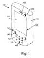
- FIG. 1is a diagram of a telecommunication device 100 according to an implementation consistent with principles of the invention.
- the telecommunication device 100may include a housing 110 , a speaker 120 , a display 130 , control buttons 140 , a keypad 150 , a plurality of microphones 160 , 161 , 162 , and an imaging unit 170 .
- the housing 110may support the components of the telecommunication device 100 .
- the speaker 120may provide audible information to the user of the telecommunication device 100 .
- the display 130may provide visual information to a user of the telecommunication device 100 .
- the display 130may render media information, such as image frames and/or video, and/or function as a viewfinder in connection with the operation of the imaging unit 170 .
- the control buttons 140may permit the user to interact with the communication device 100 to cause the telecommunication device 100 to perform one or more operations.
- the keypad 150may include a standard telephone keypad.
- the microphones 160 , 161 , 162can be unidirectional microphones and arranged in an array which creates a virtual microphone which receives audible information from the user. As will be explained below in more detail the location of the virtual microphone can be changed by adjusting the delay and gain of the acoustic signals captured by the plurality of microphones.
- the microphonescan be arranged symmetrically or asymmetrically around the telecommunication device 100 . Furthermore, the location of each microphone on the communication device 100 and the number of microphones used in the array can be varied from the layout shown in FIG. 1 and the invention is not limited thereto.
- the imaging unit 170may enable the user to capture and store video and/or images.
- an exemplary telecommunication device 100comprises a microphone array comprised of three microphones 160 , 161 , 162 , a keypad 150 , one or more speakers 120 , the display 130 , a transceiver 125 , a memory 155 that communicates with a processor 135 , an imaging unit 170 and an position sensing device 195 .
- the transceiver 125comprises a transmitter circuit 180 and a receiver circuit 145 , which respectively transmit outgoing radio frequency signals to base station transceivers and receive incoming radio frequency signals from the base station transceivers via an antenna 115 .
- the processor 135communicates with the memory 155 via an address/data bus.
- the processor 135may be, for example, a commercially available or custom microprocessor.
- the memory 155is representative of the one or more memory devices containing software and data used to provide audible feedback to a user through the speaker 120 .
- the memory 155may include, but is not limited to, the following types of devices: cache, ROM, PROM, EPROM, EEPROM, flash, SRAM and DRAM.
- the memory 155may contain various categories of software and/or data.
- the memory 155may comprise an operating system 190 .
- the operating system 190generally controls the operation of the telecommunication device 100 .
- the operating system 190may manage the telecommunication device's software and/or hardware resources and may coordinate execution of programs by the processor 135 .
- FIG. 2illustrates an exemplary software and hardware architecture that may be used to provide noise cancellation and other operations of a telecommunication device, it will be understood that the present invention is not limited to such a configuration but is intended to encompass any configuration capable of carrying out the operations described herein.
- the processor 135may be comprised of or operate like various components comprising but not limited thereto at least Digital Signal Processor (DSP) hardware including one analogue/digital converter 205 , 205 ′, 205 ′′, at least one delay element 210 , 210 ′, 210 ′′ and at least one preamplifier 215 , 215 ′, 215 ′′ and the controller 220 as illustrated in FIG. 3 .
- DSPDigital Signal Processor
- each microphonehas its own A/D converter, delay element and preamplifier but the invention is not limited thereto.
- the controller 220can control the microphone array comprised of microphones 160 , 161 , 162 by adjusting the delay and gain values that are applied to the acoustic signals received by each microphone.
- the microphone arraycreates a virtual microphone using known control techniques.
- the virtual microphonehas sensitivity lobes from which acoustic signals are received and null sections from which no or limited acoustic signal are received or dampened.
- the location of the virtual microphonecan be moved by adjusting the delay, gain, and frequency response values applied to the received signals.
- the best location for recording speech signalscan be moved around the telecommunication device 100 by adjusting the delay and gain values applied during processing.
- a position sensing device 195is incorporated into the telecommunication device 100 .
- the position sensing device 195is used to determine how the user is holding the telecommunication device 100 in relation to the user's head.
- the position sensing deviceis an accelerometer but the invention is not limited thereto.
- the accelerometer 195can create an [x,y,z] system, wherein the three sub-vectors are orthogonal in relation to each other, and the resulting vector v determined by the accelerometer 195 always points to the ground.
- the controller 220can determine the location of the virtual microphone to be able to receive acoustic signals in an approximate direction of the user's mouth. The controller 220 can then change the location of the virtual microphone to correspond to the determined position of the user's mouth. This will increase the speech component in the processed acoustic signal while decreasing the noise component, thus increasing the quality of the speech component.
- the controller 220can store various delay, gain, and frequency shape values for various predetermined positions of the telecommunication device. As a result, the controller 220 can quickly apply the appropriate delay and gain values to the acoustic signals from the microphone array once the position of the telecommunication device is determined.
- the usermay turn the device 100 in different directions illustrated, but not limited to, the arrows a, b, and c as shown in FIG. 5A .
- a first set of delay and gain valuescan be stored for use when the telecommunication device is being held in a standard manner as illustrated in FIG. 5A .
- the location of the virtual microphonecan be moved by adjusting the delay, gain, and frequency response values applied to the received signals.
- the best location for recording speech signalscan be moved in a direction illustrated by the dashed lines and oval forming a virtual microphone lobe 500 a of a virtual microphone.
- a second set of delay and gain valuescan be stored to be used when the telecommunication device is being held in the manner illustrated in FIG. 5B .
- the stored valueswould move the location of the virtual microphone down, forming a virtual microphone lobe 500 b , since the telecommunication device is being held above the user's mouth.
- a third set of delay and gain valuescan be stored to be used when the telecommunication device is being held in the manner illustrated in FIG. 5C .
- the stored valueswould move the location of the virtual microphone in a direction from the telecommunication device forming a virtual microphone lobe 500 c , since the telecommunication device is being held above and away from the user's mouth.
- a fourth set of delay and gain valuescan be stored to be used when the telecommunication device is being held in the manner illustrated in FIG. 5D .
- the stored valueswould move the location of the virtual microphone up forming a virtual microphone lobe 500 d since the user most likely be lying and thus the telecommunication device is being held in a standard matter in relation to the user's mouth.
- the decision to form a virtual microphone lobe in a direction illustrated in FIG. 5Dmay be based on a reasonableness analysis performed by the controller based on the position information received from the accelerometer 195 about the device 100 .
- This change of direction of the virtual microphonemay be delayed, because the device 100 may just be temporary moved into this position and than back to a normal position where the user sits or stands. In this case the virtual microphone lobe will be directed according to the location illustrated in FIG. 5A .
- each microphone of the microphone arrayreceives a plurality of acoustic signals.
- the controller 220receives information from the accelerometer 195 to determine the position of the telecommunication device in relation to the user's head. The controller 220 either calculates the needed delay and gain values for each received acoustic signal or simply retrieves stored delay and gain values from memory 155 for the determined position of the telecommunication device 100 in step 405 . The controller 220 then applies the selected delay and gain values to the delay elements 210 and the preamplifiers 215 in step 407 .
- the controllerthen processes the acoustic signals in a known manner using the applied delay and gain values after they have been converted into digital signals by the A/D converters 205 to produce an output signal in step 409 .
- the output signalscan then be sent to the transceiver 180 for broadcast.
- the controller 220sends the output signals as a side tone to the ear speaker 120 of the telecommunication device 100 so that the user can hear his/her part of the conversation.
- the controller 220can adjust the strength of the side tone based on the determined position of the telecommunication device. For example, the strength of the side tone can be increased when it is determined that the telecommunication device is being held away from the user's ear.
- the method according to the present inventionis suitable for implementation with aid of processing means, such as computers and/or processors. Further especially, the feature of processing digital signals are particularly suitable to be performed in a Digital Signal Processor (DSP) hardware or other dedicated hardware.
- DSPDigital Signal Processor
- the computer programspreferably comprise program code which is stored on a computer readable medium 1000 , as illustrated in FIG. 6 , which can be loaded and executed by a processing means, processor, or computer 1002 to cause it to perform the methods, respectively, according to embodiments of the present invention, preferably as any of the embodiments described with reference to FIG. 4 .
- the computer 1002 and computer program product 1000can be arranged to execute the program code sequentially where actions of the any of the methods are performed stepwise.
- the processing means, processor, or computer 1002is preferably what normally is referred to as an embedded system.
- the depicted computer readable medium 1000 and computer 1002 in FIG. 6should be construed to be for illustrative purposes only to provide understanding of the principle, and not to be construed as any direct illustration of the elements.
- the microphone arraymay be comprised of at least three or more microphones in other embodiments.
Landscapes
- Health & Medical Sciences (AREA)
- General Health & Medical Sciences (AREA)
- Otolaryngology (AREA)
- Physics & Mathematics (AREA)
- Engineering & Computer Science (AREA)
- Acoustics & Sound (AREA)
- Signal Processing (AREA)
- Circuit For Audible Band Transducer (AREA)
Abstract
Description
Claims (21)
Priority Applications (1)
| Application Number | Priority Date | Filing Date | Title |
|---|---|---|---|
| US13/100,477US8868413B2 (en) | 2011-04-06 | 2011-05-04 | Accelerometer vector controlled noise cancelling method |
Applications Claiming Priority (5)
| Application Number | Priority Date | Filing Date | Title |
|---|---|---|---|
| US201161472382P | 2011-04-06 | 2011-04-06 | |
| EP11161341 | 2011-04-06 | ||
| EP11161341.0 | 2011-04-06 | ||
| EP20110161341EP2509337B1 (en) | 2011-04-06 | 2011-04-06 | Accelerometer vector controlled noise cancelling method |
| US13/100,477US8868413B2 (en) | 2011-04-06 | 2011-05-04 | Accelerometer vector controlled noise cancelling method |
Publications (2)
| Publication Number | Publication Date |
|---|---|
| US20120259628A1 US20120259628A1 (en) | 2012-10-11 |
| US8868413B2true US8868413B2 (en) | 2014-10-21 |
Family
ID=44461827
Family Applications (1)
| Application Number | Title | Priority Date | Filing Date |
|---|---|---|---|
| US13/100,477Expired - Fee RelatedUS8868413B2 (en) | 2011-04-06 | 2011-05-04 | Accelerometer vector controlled noise cancelling method |
Country Status (2)
| Country | Link |
|---|---|
| US (1) | US8868413B2 (en) |
| EP (1) | EP2509337B1 (en) |
Cited By (2)
| Publication number | Priority date | Publication date | Assignee | Title |
|---|---|---|---|---|
| US9736578B2 (en) | 2015-06-07 | 2017-08-15 | Apple Inc. | Microphone-based orientation sensors and related techniques |
| US10349169B2 (en) | 2017-10-31 | 2019-07-09 | Bose Corporation | Asymmetric microphone array for speaker system |
Families Citing this family (16)
| Publication number | Priority date | Publication date | Assignee | Title |
|---|---|---|---|---|
| JP6267860B2 (en)* | 2011-11-28 | 2018-01-24 | 三星電子株式会社Samsung Electronics Co.,Ltd. | Audio signal transmitting apparatus, audio signal receiving apparatus and method thereof |
| JP5847006B2 (en)* | 2012-04-17 | 2016-01-20 | 京セラ株式会社 | Mobile communication terminal |
| US9438985B2 (en) | 2012-09-28 | 2016-09-06 | Apple Inc. | System and method of detecting a user's voice activity using an accelerometer |
| US9313572B2 (en) | 2012-09-28 | 2016-04-12 | Apple Inc. | System and method of detecting a user's voice activity using an accelerometer |
| GB2510117A (en)* | 2013-01-23 | 2014-07-30 | Odg Technologies Ltd | Active noise cancellation system with orientation sensor to determine ANC microphone selection |
| US9363596B2 (en) | 2013-03-15 | 2016-06-07 | Apple Inc. | System and method of mixing accelerometer and microphone signals to improve voice quality in a mobile device |
| US9332368B1 (en) | 2013-07-08 | 2016-05-03 | Google Inc. | Accelerometer or transducer on a device |
| US9204065B2 (en) | 2013-10-28 | 2015-12-01 | Nokia Corporation | Removing noise generated from a non-audio component |
| KR20180077316A (en) | 2014-03-18 | 2018-07-06 | 로베르트 보쉬 게엠베하 | Adaptive acoustic intensity analyzer |
| US10609475B2 (en)* | 2014-12-05 | 2020-03-31 | Stages Llc | Active noise control and customized audio system |
| US10187504B1 (en)* | 2016-09-23 | 2019-01-22 | Apple Inc. | Echo control based on state of a device |
| US10945080B2 (en) | 2016-11-18 | 2021-03-09 | Stages Llc | Audio analysis and processing system |
| US9980075B1 (en) | 2016-11-18 | 2018-05-22 | Stages Llc | Audio source spatialization relative to orientation sensor and output |
| CN108462763B (en)* | 2017-02-22 | 2023-08-29 | 南昌黑鲨科技有限公司 | Noise reduction terminal and noise reduction method |
| CN110234043B (en)* | 2019-05-31 | 2020-08-25 | 歌尔科技有限公司 | Sound signal processing method, device and equipment based on microphone array |
| US11935512B2 (en)* | 2022-05-17 | 2024-03-19 | Apple Inc. | Adaptive noise cancellation and speech filtering for electronic devices |
Citations (31)
| Publication number | Priority date | Publication date | Assignee | Title |
|---|---|---|---|---|
| US5353376A (en)* | 1992-03-20 | 1994-10-04 | Texas Instruments Incorporated | System and method for improved speech acquisition for hands-free voice telecommunication in a noisy environment |
| US5757937A (en)* | 1996-01-31 | 1998-05-26 | Nippon Telegraph And Telephone Corporation | Acoustic noise suppressor |
| US6265264B1 (en)* | 1999-10-05 | 2001-07-24 | Samsung Electronics Co., Ltd. | Method of doping and HSG surface of a capacitor electrode with PH3 under a low temperature/high pressure processing condition |
| US20020071573A1 (en)* | 1997-09-11 | 2002-06-13 | Finn Brian M. | DVE system with customized equalization |
| US6411927B1 (en)* | 1998-09-04 | 2002-06-25 | Matsushita Electric Corporation Of America | Robust preprocessing signal equalization system and method for normalizing to a target environment |
| US6469732B1 (en)* | 1998-11-06 | 2002-10-22 | Vtel Corporation | Acoustic source location using a microphone array |
| US20020161577A1 (en)* | 2001-04-25 | 2002-10-31 | International Business Mashines Corporation | Audio source position detection and audio adjustment |
| US20020176589A1 (en)* | 2001-04-14 | 2002-11-28 | Daimlerchrysler Ag | Noise reduction method with self-controlling interference frequency |
| US20030185410A1 (en)* | 2002-03-27 | 2003-10-02 | Samsung Electronics Co., Ltd. | Orthogonal circular microphone array system and method for detecting three-dimensional direction of sound source using the same |
| US20040040621A1 (en)* | 2002-05-10 | 2004-03-04 | Zaidanhouzin Kitakyushu Sangyou Gakujutsu Suishin Kikou | Recovering method of target speech based on split spectra using sound sources' locational information |
| US20040066941A1 (en)* | 2002-09-17 | 2004-04-08 | Kabushiki Kaisha Toshiba | Directional setting apparatus, directional setting system, directional setting method and directional setting program |
| US6738481B2 (en)* | 2001-01-10 | 2004-05-18 | Ericsson Inc. | Noise reduction apparatus and method |
| US20040221163A1 (en)* | 2003-05-02 | 2004-11-04 | Jorgensen Jimi T. | Pervasive, user-centric network security enabled by dynamic datagram switch and an on-demand authentication and encryption scheme through mobile intelligent data carriers |
| US6879952B2 (en)* | 2000-04-26 | 2005-04-12 | Microsoft Corporation | Sound source separation using convolutional mixing and a priori sound source knowledge |
| US20050080616A1 (en)* | 2001-07-19 | 2005-04-14 | Johahn Leung | Recording a three dimensional auditory scene and reproducing it for the individual listener |
| US20050185813A1 (en)* | 2004-02-24 | 2005-08-25 | Microsoft Corporation | Method and apparatus for multi-sensory speech enhancement on a mobile device |
| US20050254664A1 (en)* | 2004-05-13 | 2005-11-17 | Kwong Wah Y | Noise cancellation methodology for electronic devices |
| US20070230712A1 (en) | 2004-09-07 | 2007-10-04 | Koninklijke Philips Electronics, N.V. | Telephony Device with Improved Noise Suppression |
| US20080298602A1 (en)* | 2007-05-22 | 2008-12-04 | Tobias Wolff | System for processing microphone signals to provide an output signal with reduced interference |
| US20090003626A1 (en) | 2007-06-13 | 2009-01-01 | Burnett Gregory C | Dual Omnidirectional Microphone Array (DOMA) |
| US20090010449A1 (en)* | 2003-03-27 | 2009-01-08 | Burnett Gregory C | Microphone Array With Rear Venting |
| US20090129609A1 (en)* | 2007-11-19 | 2009-05-21 | Samsung Electronics Co., Ltd. | Method and apparatus for acquiring multi-channel sound by using microphone array |
| US20090144063A1 (en)* | 2006-02-03 | 2009-06-04 | Seung-Kwon Beack | Method and apparatus for control of randering multiobject or multichannel audio signal using spatial cue |
| US20090179914A1 (en)* | 2008-01-10 | 2009-07-16 | Mikael Dahlke | System and method for navigating a 3d graphical user interface |
| US20090210227A1 (en)* | 2008-02-15 | 2009-08-20 | Kabushiki Kaisha Toshiba | Voice recognition apparatus and method for performing voice recognition |
| US20100017205A1 (en)* | 2008-07-18 | 2010-01-21 | Qualcomm Incorporated | Systems, methods, apparatus, and computer program products for enhanced intelligibility |
| US20100081487A1 (en) | 2008-09-30 | 2010-04-01 | Apple Inc. | Multiple microphone switching and configuration |
| US7720683B1 (en)* | 2003-06-13 | 2010-05-18 | Sensory, Inc. | Method and apparatus of specifying and performing speech recognition operations |
| US20110075859A1 (en)* | 2009-09-28 | 2011-03-31 | Samsung Electronics Co., Ltd. | Apparatus for gain calibration of a microphone array and method thereof |
| US20110158425A1 (en)* | 2009-12-25 | 2011-06-30 | Fujitsu Limited | Microphone directivity control apparatus |
| US8249862B1 (en)* | 2009-04-15 | 2012-08-21 | Mediatek Inc. | Audio processing apparatuses |
- 2011
- 2011-04-06EPEP20110161341patent/EP2509337B1/ennot_activeNot-in-force
- 2011-05-04USUS13/100,477patent/US8868413B2/ennot_activeExpired - Fee Related
Patent Citations (31)
| Publication number | Priority date | Publication date | Assignee | Title |
|---|---|---|---|---|
| US5353376A (en)* | 1992-03-20 | 1994-10-04 | Texas Instruments Incorporated | System and method for improved speech acquisition for hands-free voice telecommunication in a noisy environment |
| US5757937A (en)* | 1996-01-31 | 1998-05-26 | Nippon Telegraph And Telephone Corporation | Acoustic noise suppressor |
| US20020071573A1 (en)* | 1997-09-11 | 2002-06-13 | Finn Brian M. | DVE system with customized equalization |
| US6411927B1 (en)* | 1998-09-04 | 2002-06-25 | Matsushita Electric Corporation Of America | Robust preprocessing signal equalization system and method for normalizing to a target environment |
| US6469732B1 (en)* | 1998-11-06 | 2002-10-22 | Vtel Corporation | Acoustic source location using a microphone array |
| US6265264B1 (en)* | 1999-10-05 | 2001-07-24 | Samsung Electronics Co., Ltd. | Method of doping and HSG surface of a capacitor electrode with PH3 under a low temperature/high pressure processing condition |
| US6879952B2 (en)* | 2000-04-26 | 2005-04-12 | Microsoft Corporation | Sound source separation using convolutional mixing and a priori sound source knowledge |
| US6738481B2 (en)* | 2001-01-10 | 2004-05-18 | Ericsson Inc. | Noise reduction apparatus and method |
| US20020176589A1 (en)* | 2001-04-14 | 2002-11-28 | Daimlerchrysler Ag | Noise reduction method with self-controlling interference frequency |
| US20020161577A1 (en)* | 2001-04-25 | 2002-10-31 | International Business Mashines Corporation | Audio source position detection and audio adjustment |
| US20050080616A1 (en)* | 2001-07-19 | 2005-04-14 | Johahn Leung | Recording a three dimensional auditory scene and reproducing it for the individual listener |
| US20030185410A1 (en)* | 2002-03-27 | 2003-10-02 | Samsung Electronics Co., Ltd. | Orthogonal circular microphone array system and method for detecting three-dimensional direction of sound source using the same |
| US20040040621A1 (en)* | 2002-05-10 | 2004-03-04 | Zaidanhouzin Kitakyushu Sangyou Gakujutsu Suishin Kikou | Recovering method of target speech based on split spectra using sound sources' locational information |
| US20040066941A1 (en)* | 2002-09-17 | 2004-04-08 | Kabushiki Kaisha Toshiba | Directional setting apparatus, directional setting system, directional setting method and directional setting program |
| US20090010449A1 (en)* | 2003-03-27 | 2009-01-08 | Burnett Gregory C | Microphone Array With Rear Venting |
| US20040221163A1 (en)* | 2003-05-02 | 2004-11-04 | Jorgensen Jimi T. | Pervasive, user-centric network security enabled by dynamic datagram switch and an on-demand authentication and encryption scheme through mobile intelligent data carriers |
| US7720683B1 (en)* | 2003-06-13 | 2010-05-18 | Sensory, Inc. | Method and apparatus of specifying and performing speech recognition operations |
| US20050185813A1 (en)* | 2004-02-24 | 2005-08-25 | Microsoft Corporation | Method and apparatus for multi-sensory speech enhancement on a mobile device |
| US20050254664A1 (en)* | 2004-05-13 | 2005-11-17 | Kwong Wah Y | Noise cancellation methodology for electronic devices |
| US20070230712A1 (en) | 2004-09-07 | 2007-10-04 | Koninklijke Philips Electronics, N.V. | Telephony Device with Improved Noise Suppression |
| US20090144063A1 (en)* | 2006-02-03 | 2009-06-04 | Seung-Kwon Beack | Method and apparatus for control of randering multiobject or multichannel audio signal using spatial cue |
| US20080298602A1 (en)* | 2007-05-22 | 2008-12-04 | Tobias Wolff | System for processing microphone signals to provide an output signal with reduced interference |
| US20090003626A1 (en) | 2007-06-13 | 2009-01-01 | Burnett Gregory C | Dual Omnidirectional Microphone Array (DOMA) |
| US20090129609A1 (en)* | 2007-11-19 | 2009-05-21 | Samsung Electronics Co., Ltd. | Method and apparatus for acquiring multi-channel sound by using microphone array |
| US20090179914A1 (en)* | 2008-01-10 | 2009-07-16 | Mikael Dahlke | System and method for navigating a 3d graphical user interface |
| US20090210227A1 (en)* | 2008-02-15 | 2009-08-20 | Kabushiki Kaisha Toshiba | Voice recognition apparatus and method for performing voice recognition |
| US20100017205A1 (en)* | 2008-07-18 | 2010-01-21 | Qualcomm Incorporated | Systems, methods, apparatus, and computer program products for enhanced intelligibility |
| US20100081487A1 (en) | 2008-09-30 | 2010-04-01 | Apple Inc. | Multiple microphone switching and configuration |
| US8249862B1 (en)* | 2009-04-15 | 2012-08-21 | Mediatek Inc. | Audio processing apparatuses |
| US20110075859A1 (en)* | 2009-09-28 | 2011-03-31 | Samsung Electronics Co., Ltd. | Apparatus for gain calibration of a microphone array and method thereof |
| US20110158425A1 (en)* | 2009-12-25 | 2011-06-30 | Fujitsu Limited | Microphone directivity control apparatus |
Non-Patent Citations (1)
| Title |
|---|
| Extended European Search Report of corresponding European Patent Application No. 11161341.0, dated Sep. 2, 2011. |
Cited By (3)
| Publication number | Priority date | Publication date | Assignee | Title |
|---|---|---|---|---|
| US9736578B2 (en) | 2015-06-07 | 2017-08-15 | Apple Inc. | Microphone-based orientation sensors and related techniques |
| US10349169B2 (en) | 2017-10-31 | 2019-07-09 | Bose Corporation | Asymmetric microphone array for speaker system |
| US11134339B2 (en) | 2017-10-31 | 2021-09-28 | Bose Corporation | Asymmetric microphone array for speaker system |
Also Published As
| Publication number | Publication date |
|---|---|
| US20120259628A1 (en) | 2012-10-11 |
| EP2509337B1 (en) | 2014-09-24 |
| EP2509337A1 (en) | 2012-10-10 |
Similar Documents
| Publication | Publication Date | Title |
|---|---|---|
| US8868413B2 (en) | Accelerometer vector controlled noise cancelling method | |
| US10269369B2 (en) | System and method of noise reduction for a mobile device | |
| US8787587B1 (en) | Selection of system parameters based on non-acoustic sensor information | |
| CN102696239B (en) | a device | |
| US9749731B2 (en) | Sidetone generation using multiple microphones | |
| US9197974B1 (en) | Directional audio capture adaptation based on alternative sensory input | |
| JP2022526761A (en) | Beam forming with blocking function Automatic focusing, intra-regional focusing, and automatic placement of microphone lobes | |
| US9749737B2 (en) | Decisions on ambient noise suppression in a mobile communications handset device | |
| KR101260131B1 (en) | Audio source proximity estimation using sensor array for noise reduction | |
| US20140270202A1 (en) | Apparatus with Adaptive Audio Adjustment Based on Surface Proximity, Surface Type and Motion | |
| KR20120101457A (en) | Audio zoom | |
| US9521486B1 (en) | Frequency based beamforming | |
| US20130121498A1 (en) | Noise reduction using microphone array orientation information | |
| WO2016028448A1 (en) | Method and apparatus for estimating talker distance | |
| JP2007290691A (en) | Vehicle communication system | |
| WO2013078474A1 (en) | Processing signals | |
| WO2014101429A1 (en) | Noise reduction method and device for bi-microphone of terminal | |
| WO2013049740A2 (en) | Processing signals | |
| US20140355775A1 (en) | Wired and wireless microphone arrays | |
| US20100098266A1 (en) | Multi-channel audio device | |
| CN113544775A (en) | Audio signal enhancement for head-mounted audio devices | |
| US9729967B2 (en) | Feedback canceling system and method | |
| EP4133752A1 (en) | Method and apparatus for location-based audio signal compensation | |
| US20230308817A1 (en) | Hearing system comprising a hearing aid and an external processing device | |
| CN102970638B (en) | Processing signals |
Legal Events
| Date | Code | Title | Description |
|---|---|---|---|
| AS | Assignment | Owner name:SONY ERICSSON MOBILE COMMUNICATIONS, SWEDEN Free format text:ASSIGNMENT OF ASSIGNORS INTEREST;ASSIGNOR:SIOTIS, GEORG;REEL/FRAME:026222/0635 Effective date:20110503 | |
| AS | Assignment | Owner name:SONY CORPORATION, JAPAN Free format text:ASSIGNMENT OF PARTIAL INTEREST;ASSIGNOR:SONY MOBILE COMMUNICATIONS AB;REEL/FRAME:033694/0881 Effective date:20140813 Owner name:SONY MOBILE COMMUNICATIONS AB, SWEDEN Free format text:CHANGE OF NAME;ASSIGNOR:SONY ERICSSON MOBILE COMMUNICATIONS AB;REEL/FRAME:033694/0877 Effective date:20120924 Owner name:SONY MOBILE COMMUNICATIONS AB, SWEDEN Free format text:ASSIGNMENT OF PARTIAL INTEREST;ASSIGNOR:SONY MOBILE COMMUNICATIONS AB;REEL/FRAME:033694/0881 Effective date:20140813 | |
| STCF | Information on status: patent grant | Free format text:PATENTED CASE | |
| AS | Assignment | Owner name:SONY MOBILE COMMUNICATIONS INC., JAPAN Free format text:ASSIGNMENT OF ASSIGNORS INTEREST;ASSIGNOR:SONY CORPORATION;REEL/FRAME:043943/0631 Effective date:20170914 | |
| AS | Assignment | Owner name:SONY MOBILE COMMUNICATIONS INC., JAPAN Free format text:ASSIGNMENT OF ASSIGNORS INTEREST;ASSIGNOR:SONY MOBILE COMMUNICATIONS AB;REEL/FRAME:043951/0529 Effective date:20170912 | |
| MAFP | Maintenance fee payment | Free format text:PAYMENT OF MAINTENANCE FEE, 4TH YEAR, LARGE ENTITY (ORIGINAL EVENT CODE: M1551) Year of fee payment:4 | |
| AS | Assignment | Owner name:SONY CORPORATION, JAPAN Free format text:ASSIGNMENT OF ASSIGNORS INTEREST;ASSIGNOR:SONY MOBILE COMMUNICATIONS, INC.;REEL/FRAME:048691/0134 Effective date:20190325 | |
| FEPP | Fee payment procedure | Free format text:MAINTENANCE FEE REMINDER MAILED (ORIGINAL EVENT CODE: REM.); ENTITY STATUS OF PATENT OWNER: LARGE ENTITY | |
| LAPS | Lapse for failure to pay maintenance fees | Free format text:PATENT EXPIRED FOR FAILURE TO PAY MAINTENANCE FEES (ORIGINAL EVENT CODE: EXP.); ENTITY STATUS OF PATENT OWNER: LARGE ENTITY | |
| STCH | Information on status: patent discontinuation | Free format text:PATENT EXPIRED DUE TO NONPAYMENT OF MAINTENANCE FEES UNDER 37 CFR 1.362 | |
| FP | Lapsed due to failure to pay maintenance fee | Effective date:20221021 |