US8867352B2 - Receiver based power efficient transmitter for ethernet - Google Patents
Receiver based power efficient transmitter for ethernetDownload PDFInfo
- Publication number
- US8867352B2 US8867352B2US12/770,222US77022210AUS8867352B2US 8867352 B2US8867352 B2US 8867352B2US 77022210 AUS77022210 AUS 77022210AUS 8867352 B2US8867352 B2US 8867352B2
- Authority
- US
- United States
- Prior art keywords
- value
- magnitude
- signal
- transceiver
- magnitude value
- Prior art date
- Legal status (The legal status is an assumption and is not a legal conclusion. Google has not performed a legal analysis and makes no representation as to the accuracy of the status listed.)
- Active, expires
Links
- 238000000034methodMethods0.000claimsabstractdescription17
- 238000004891communicationMethods0.000claimsdescription33
- 230000002238attenuated effectEffects0.000abstract1
- 230000009286beneficial effectEffects0.000abstract1
- 230000005540biological transmissionEffects0.000description8
- 230000006870functionEffects0.000description2
- 230000003287optical effectEffects0.000description2
- 230000006978adaptationEffects0.000description1
- 238000013459approachMethods0.000description1
- 238000013461designMethods0.000description1
- 230000000694effectsEffects0.000description1
- 230000007246mechanismEffects0.000description1
- 238000012986modificationMethods0.000description1
- 230000004048modificationEffects0.000description1
- 230000000644propagated effectEffects0.000description1
- 238000012360testing methodMethods0.000description1
Images


Classifications
- H—ELECTRICITY
- H04—ELECTRIC COMMUNICATION TECHNIQUE
- H04L—TRANSMISSION OF DIGITAL INFORMATION, e.g. TELEGRAPHIC COMMUNICATION
- H04L12/00—Data switching networks
- H04L12/02—Details
- H04L12/10—Current supply arrangements
- H—ELECTRICITY
- H04—ELECTRIC COMMUNICATION TECHNIQUE
- H04L—TRANSMISSION OF DIGITAL INFORMATION, e.g. TELEGRAPHIC COMMUNICATION
- H04L12/00—Data switching networks
- H04L12/28—Data switching networks characterised by path configuration, e.g. LAN [Local Area Networks] or WAN [Wide Area Networks]
- H04L12/40—Bus networks
- H04L12/40006—Architecture of a communication node
- H04L12/40045—Details regarding the feeding of energy to the node from the bus
- H—ELECTRICITY
- H04—ELECTRIC COMMUNICATION TECHNIQUE
- H04L—TRANSMISSION OF DIGITAL INFORMATION, e.g. TELEGRAPHIC COMMUNICATION
- H04L25/00—Baseband systems
- H04L25/02—Details ; arrangements for supplying electrical power along data transmission lines
- H04L25/0264—Arrangements for coupling to transmission lines
- H04L25/028—Arrangements specific to the transmitter end
- H04L25/0286—Provision of wave shaping within the driver
- H04L25/0288—Provision of wave shaping within the driver the shape being matched to the transmission line
- H—ELECTRICITY
- H04—ELECTRIC COMMUNICATION TECHNIQUE
- H04L—TRANSMISSION OF DIGITAL INFORMATION, e.g. TELEGRAPHIC COMMUNICATION
- H04L5/00—Arrangements affording multiple use of the transmission path
- H04L5/14—Two-way operation using the same type of signal, i.e. duplex
- H04L5/1423—Two-way operation using the same type of signal, i.e. duplex for simultaneous baseband signals
- H—ELECTRICITY
- H04—ELECTRIC COMMUNICATION TECHNIQUE
- H04L—TRANSMISSION OF DIGITAL INFORMATION, e.g. TELEGRAPHIC COMMUNICATION
- H04L12/00—Data switching networks
- H04L12/28—Data switching networks characterised by path configuration, e.g. LAN [Local Area Networks] or WAN [Wide Area Networks]
- H04L12/40—Bus networks
- H04L12/40006—Architecture of a communication node
- H04L12/40032—Details regarding a bus interface enhancer
- H—ELECTRICITY
- H04—ELECTRIC COMMUNICATION TECHNIQUE
- H04L—TRANSMISSION OF DIGITAL INFORMATION, e.g. TELEGRAPHIC COMMUNICATION
- H04L25/00—Baseband systems
- H04L25/02—Details ; arrangements for supplying electrical power along data transmission lines
- H04L25/0264—Arrangements for coupling to transmission lines
- H04L25/0278—Arrangements for impedance matching
Definitions
- the present inventiongenerally relates to reducing required transmitter drive current in an Ethernet environment.
- FIG. 1shows a communications system
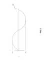
- FIG. 2shows an example transmitted signal wave
- FIG. 3shows an example received signal wave.
- FIG. 4shows superimposed transmitted and received signal waves.
- FIGS. 5 and 6show flowcharts depicting various methods.
- the present inventionis directed to a receiver based power efficient transmitter for Ethernet.
- This specificationdiscloses one or more embodiments that incorporate the features of this invention.
- the disclosed embodiment(s)merely exemplify the invention.
- the scope of the inventionis not limited to the disclosed embodiment(s).
- the inventionis defined by the claims appended hereto.
- Embodiments of the inventionmay be implemented in hardware, firmware, software, or any combination thereof Embodiments of the invention may also be implemented as instructions stored on a machine-readable medium, which may be read and executed by one or more processors.
- a machine-readable mediummay include any mechanism for storing or transmitting information in a form readable by a machine (e.g., a computing device).
- a machine-readable mediummay include read only memory (ROM); random access memory (RAM); magnetic disk storage media; optical storage media; flash memory devices; electrical, optical, acoustical or other forms of propagated signals (e.g., carrier waves, infrared signals, digital signals, etc.), and others.
- firmware, software, routines, instructionsmay be described herein as performing certain actions. However, it should be appreciated that such descriptions are merely for convenience and that such actions in fact result from computing devices, processors, controllers, or other devices executing the firmware, software, routines, instructions, etc.
- the Institute of Electrical and Electronics Engineersinter alia sets the standards for communication devices interchanging information using an Ethernet protocol to allow different manufacturers to produce devices complying with the same specifications, while being compatible to each other.
- 10 BaseTis a Ethernet standard protocol for transmitting digital information at a transmission speed of 10 Mbit/s
- 100 BaseTdefines digital data transmission at 100 Mbit/s
- IEEE 802.3defines the parameters for the combined 10 BaseT/100 BaseT/1000 BaseT transmitters using unshielded twisted pair (UTP) lines. For example, IEEE 802.3 defines what voltage levels should be output on the lines, how the switching between the different voltage levels defined for the protocols should be handled, and what termination impedance should be guaranteed on the line.
- the highest transmitter linearityis in 1000 BaseT in the presence of an interferer put on the line in full duplex.
- the highest accuracy of signalsis in 100 BaseT mode when fast settling with accurate rise time and accurate output voltage are specified.
- the 10 BaseT protocoldesires the highest voltage swing.
- Ethernet transmitter parameterscan be found in, e.g., co-pending, co-owned U.S. Published Patent Appl. No. 2007-0296456, which is incorporated by reference herein in its entirety.
- EEEEnergy Efficient Ethernet
- An embodiment of the present inventionprovides a system comprising a transceiver, a magnitude determining device, and a controller.
- the transceiveris configured to operate in full-duplex mode.
- the magnitude determining deviceis configured to generate a magnitude value of a signal received by the transceiver.
- the controlleris configured to generate a control signal based on the magnitude value.
- the control signaladjusts current driving the transceiver during transmission of a transmitted signal.
- control signaladjusts the current to a minimum current value that also allows for generation of a threshold voltage value of the transmitted signal, and can also allow for generation of a threshold value of a receive signal, thereby substantially reducing power consumption of the transceiver.
- a systemcomprising a transceiver and a controller.
- the transceiveris configured to operate in full-duplex mode with a remote transceiver over a communications medium.
- the controlleris configured to generate a control signal based on a length value of the communication medium. The control signal adjusts current driving the transceiver during transmission of a transmitted signal.
- a methodcomprising the following steps. Operating a transceiver in full duplex mode. Determining a magnitude of a received signal. Adjusting current driving the transceiver during transmission of a transmitted signal based on the magnitude of the received signal.
- a methodcomprising the following steps. Operating a transceiver in full duplex mode, whereby the transceiver communicates with another transceiver via a communications medium. Adjusting current, based on a length of the communications medium, the current driving a transmitting portion of the transceiver.
- FIG. 1shows a communications system 100 .
- communications system 100can be an Ethernet communications system operating in full duplex mode.
- System 100comprises first and second transceivers 102 and 104 coupled via a communications medium 103 (e.g., UTP lines) having a length L.
- a communications medium 103e.g., UTP lines
- signalsare substantially transmitted and received to and from first and second transceivers 102 and 104 along communications medium 103 .
- first transceiver 102includes a transmitting portion Tx 106 and a receiving portion Rx 108 .
- second transceiver portion 104includes a transmitting portion Tx 110 and a receiving portion Rx 112 .
- first transceiver 102is on a device under test (DUT) side of communications system 100 and second transceiver 104 is on a link partner (LP) side of communications system 100 .
- the DUT sidealso includes an analog-to-digital converter ADC 114 , which in one example can be within, i.e., a part of transceiver 102 , and a controller 116 .
- ADC 114analog-to-digital converter
- controller 116controller
- FIG. 2shows an example transmitted signal wave 200 with a magnitude Vtx and FIG. 3 shows an example received signal wave 300 with a magnitude Vrx.
- signal 200is a sine wave and signal 300 is a square wave, any shape signal can be used for signals 200 and 300 .
- first transceiver 102is a main transceiver.
- transmitted signal 200 generated and transmitted from first transceiver 102can be substantially larger in magnitude than received signal 300 received by first transceiver 102 .
- the losscan vary depending on the length of medium 103 . If the loss is too small, received signal 300 can be large, where a worst case can be when the loss is zero, and received signal 300 is substantially equal to transmitted 106 signal in amplitude.
- transmitting portion Tx 106Without knowing a magnitude of receive signal 300 , transmitting portion Tx 106 needs enough current to generate a required minimum magnitude Vt of signal 400 , e.g., a worst case scenario of Vt, which may unnecessarily increase drive current and power consumption of transmitting portion Tx 106 , as discussed above.
- Vtxis fixed and set to 2 Vppd.
- Vrxis the receive signal from the link-partner.
- a maximum signal swing on Vrxis 2 Vppd since the link-partner 110 meets IEEE specification.
- Vrxis reduced over a longer cable due to the loss over the communication medium 103 .
- the TX driverSince Vrx is received at the TX driver of 106 , the TX driver provides output current to sink or source Vrx. The additional current causes higher power consumption of 106 . If the driver design has no information of the incoming RX signal strength, the driver accounts for the worst case scenario, which is 2 Vppd. This is equivalent to 4 Vppd of Vt (400) at 116 .
- the driving currentbe adjusted to be at minimal level needed to still achieve a required Vrx, e.g., to be adjustable based on an actual received signal 300 rather than an worst case received signal 300 .
- controller 116receives a magnitude value of received signal 300 .
- the magnitudecan be represented by a digital signal 115 generated based on received signal 300 begin processed by ADC 114 .
- controller 116can produce an optimal control signal 117 , e.g., a drive current, which optimally drives transmitting portion Tx 106 to produce a threshold value of voltage for transmitted signal Vtx 200 and Vrx 300 to meet the Ethernet parameters.
- a voltage value for transmitted signal 400(Vtx plus Vrx) can be adjusted, e.g., reduced, to substantially reduce or optimize power consumption of transmitting portion Tx 106 .
- thismay be done in an iterative approach with an initial current value being chosen based on historical received signal magnitudes. Then, after determining an actual magnitude of the received signal, the current value is adjusted until a steady state value is determined.
- controller 116receives a length value L of communications medium 103 . Based on the length value L, controller 116 can produce control signal 117 , e.g., a current, which optimally drives transmitting portion Tx 106 to produce a threshold value of voltage for total signal 400 to meet Ethernet parameters.
- control signal 117can be based on a known lossiness of communications medium 103 that can be based on the length value L of communications medium 103 , which correlates to an expected magnitude level of received signal 300 .
- a combined signal 400 ′can be slightly less magnitude than combined signal 400 based on received signal 300 coming from a lossier medium, which reduces its magnitude and reduces the combined signal magnitude.
- a voltage Vtxcan be adjusted, e.g., reduced, to substantially reduce or optimize power consumption of transmitting portion Tx 106 when an actual value of received signal 300 is below a theoretical or expected value of received signal 300 .
- FIG. 5shows a flowchart depicting a method 500 .
- a transceiveroperates in full duplex mode.
- a magnitude of a received signalis determined.
- a current driving the transceiver during transmission of a transmitted signalis adjusted based on the magnitude of the received signal.
- FIG. 6shows a flowchart depicting a method 600 .
- a transceiveroperates in full duplex mode, whereby the transceiver communicates with another transceiver via a communications medium.
- currentis adjusted, based on a length of the communications medium, where the current drives a transmitting portion of the transceiver.
Landscapes
- Engineering & Computer Science (AREA)
- Signal Processing (AREA)
- Computer Networks & Wireless Communication (AREA)
- Power Engineering (AREA)
- Small-Scale Networks (AREA)
- Dc Digital Transmission (AREA)
Abstract
Description
Claims (20)
Priority Applications (1)
| Application Number | Priority Date | Filing Date | Title |
|---|---|---|---|
| US12/770,222US8867352B2 (en) | 2009-12-31 | 2010-04-29 | Receiver based power efficient transmitter for ethernet |
Applications Claiming Priority (2)
| Application Number | Priority Date | Filing Date | Title |
|---|---|---|---|
| US29151409P | 2009-12-31 | 2009-12-31 | |
| US12/770,222US8867352B2 (en) | 2009-12-31 | 2010-04-29 | Receiver based power efficient transmitter for ethernet |
Publications (2)
| Publication Number | Publication Date |
|---|---|
| US20110158137A1 US20110158137A1 (en) | 2011-06-30 |
| US8867352B2true US8867352B2 (en) | 2014-10-21 |
Family
ID=44187469
Family Applications (1)
| Application Number | Title | Priority Date | Filing Date |
|---|---|---|---|
| US12/770,222Active2031-08-23US8867352B2 (en) | 2009-12-31 | 2010-04-29 | Receiver based power efficient transmitter for ethernet |
Country Status (1)
| Country | Link |
|---|---|
| US (1) | US8867352B2 (en) |
Families Citing this family (2)
| Publication number | Priority date | Publication date | Assignee | Title |
|---|---|---|---|---|
| EP3266145B1 (en)* | 2015-03-05 | 2019-07-31 | Telefonaktiebolaget LM Ericsson (publ) | Full-duplex power reporting |
| US9929852B2 (en)* | 2015-08-04 | 2018-03-27 | Futurewei Technologies, Inc. | System and method for full duplex link adaptation in a full duplex communications system |
Citations (11)
| Publication number | Priority date | Publication date | Assignee | Title |
|---|---|---|---|---|
| US5247540A (en)* | 1990-10-10 | 1993-09-21 | Jay Hoge | Reversible data link |
| US5541759A (en)* | 1995-05-09 | 1996-07-30 | Microsym Computers, Inc. | Single fiber transceiver and network |
| US6282177B1 (en)* | 1998-03-04 | 2001-08-28 | 3Com Corporation | Method and apparatus for dynamically controlling the bias current in a receiver in response to the transmitter power |
| US20050041727A1 (en)* | 1998-08-28 | 2005-02-24 | Agazi Oscar E. | PHY control module for a multi-pair gigabit transceiver |
| US20060120491A1 (en)* | 2004-12-02 | 2006-06-08 | Rdc Semiconductor Co., Ltd. | Receiver with baseline wander compensation |
| US20070296456A1 (en) | 2006-05-11 | 2007-12-27 | Van Der Goes Frank | Low-power ethernet transmitter |
| US20090135752A1 (en)* | 2007-11-27 | 2009-05-28 | Motorola Inc. | A wirelesss communication device and method |
| US20090274201A1 (en)* | 2007-01-15 | 2009-11-05 | Hangzhou H3C Technologies Co., Ltd. | Ethernet transceiver and ethernet transmission method based on coax network |
| US20090290659A1 (en)* | 2008-05-21 | 2009-11-26 | Entropic Communications, Inc. | Channel stacking system and method of operation |
| US7706917B1 (en)* | 2004-07-07 | 2010-04-27 | Irobot Corporation | Celestial navigation system for an autonomous robot |
| US20100151799A1 (en)* | 2008-12-16 | 2010-06-17 | Electronics And Telecommunications Research Institute | Transceiver using millimeter-wave |
- 2010
- 2010-04-29USUS12/770,222patent/US8867352B2/enactiveActive
Patent Citations (12)
| Publication number | Priority date | Publication date | Assignee | Title |
|---|---|---|---|---|
| US5247540A (en)* | 1990-10-10 | 1993-09-21 | Jay Hoge | Reversible data link |
| US5247540B1 (en)* | 1990-10-10 | 1995-12-05 | Longacre & White | Reversible data link |
| US5541759A (en)* | 1995-05-09 | 1996-07-30 | Microsym Computers, Inc. | Single fiber transceiver and network |
| US6282177B1 (en)* | 1998-03-04 | 2001-08-28 | 3Com Corporation | Method and apparatus for dynamically controlling the bias current in a receiver in response to the transmitter power |
| US20050041727A1 (en)* | 1998-08-28 | 2005-02-24 | Agazi Oscar E. | PHY control module for a multi-pair gigabit transceiver |
| US7706917B1 (en)* | 2004-07-07 | 2010-04-27 | Irobot Corporation | Celestial navigation system for an autonomous robot |
| US20060120491A1 (en)* | 2004-12-02 | 2006-06-08 | Rdc Semiconductor Co., Ltd. | Receiver with baseline wander compensation |
| US20070296456A1 (en) | 2006-05-11 | 2007-12-27 | Van Der Goes Frank | Low-power ethernet transmitter |
| US20090274201A1 (en)* | 2007-01-15 | 2009-11-05 | Hangzhou H3C Technologies Co., Ltd. | Ethernet transceiver and ethernet transmission method based on coax network |
| US20090135752A1 (en)* | 2007-11-27 | 2009-05-28 | Motorola Inc. | A wirelesss communication device and method |
| US20090290659A1 (en)* | 2008-05-21 | 2009-11-26 | Entropic Communications, Inc. | Channel stacking system and method of operation |
| US20100151799A1 (en)* | 2008-12-16 | 2010-06-17 | Electronics And Telecommunications Research Institute | Transceiver using millimeter-wave |
Also Published As
| Publication number | Publication date |
|---|---|
| US20110158137A1 (en) | 2011-06-30 |
Similar Documents
| Publication | Publication Date | Title |
|---|---|---|
| US20180129627A1 (en) | Receiver training during a sata out of band sequence | |
| US10367547B2 (en) | Devices and methods for power consumption control in powerline communications systems and apparatus | |
| US8670555B2 (en) | Communication apparatus for rapidly adjusting analog echo cancellation circuit and related echo cancellation method | |
| TW201316178A (en) | Method for adaptively driving transmission data and communication device using the same | |
| US7913008B2 (en) | Auto-detection system and method for communication protocol | |
| US11843483B2 (en) | Method and apparatus for training a full-duplex communication link | |
| KR101341140B1 (en) | Mobile communication terminal | |
| US8867352B2 (en) | Receiver based power efficient transmitter for ethernet | |
| US20150071136A1 (en) | Full-Duplex Driver with Hybrid Adaptation | |
| CN104969629A (en) | Method and device for adjusting sending power | |
| US11336331B2 (en) | Power delivery and data communication over a single pair of cables | |
| US8665933B2 (en) | Data transmitting and receiving method and device for communication and system thereof | |
| TWI715115B (en) | Communication device capable of echo cancellation | |
| TW201543223A (en) | A method of sending a signal and its device | |
| TWI478489B (en) | Receive device and its auto gain control method | |
| JP5672597B2 (en) | Transmission terminal and transmission system | |
| JP2021022772A (en) | Radio communication equipment and communication control method | |
| US20130244585A1 (en) | Transmission Power Control Negotiation Method and Wireless Communication System Using the Same | |
| KR20150057951A (en) | Non-contact type power supplying apparatus and non-contact type power supplying method | |
| US10698473B2 (en) | Method and apparatus for reducing ethernet power consumption for vehicles | |
| EP1906579A3 (en) | Method and apparatus for transmitting data and method and apparatus for receiving data | |
| CN105830353A (en) | Power line communication for lighting systems | |
| EP2900021A1 (en) | Power back-off on channels with cyclo-stationary noise | |
| CN108029071B (en) | low energy communication link communication protocol | |
| EP4554161A1 (en) | Ethernet device that performs cable diagnosis by using ieee 802.3 compliant waveform and associated ethernet cable diagnosis method |
Legal Events
| Date | Code | Title | Description |
|---|---|---|---|
| AS | Assignment | Owner name:BROADCOM CORPORATION, CALIFORNIA Free format text:ASSIGNMENT OF ASSIGNORS INTEREST;ASSIGNORS:TAM, DEREK;CHAN, KEVIN TUNGHAI;SIGNING DATES FROM 20100331 TO 20100419;REEL/FRAME:024311/0452 | |
| STCF | Information on status: patent grant | Free format text:PATENTED CASE | |
| CC | Certificate of correction | ||
| AS | Assignment | Owner name:BANK OF AMERICA, N.A., AS COLLATERAL AGENT, NORTH CAROLINA Free format text:PATENT SECURITY AGREEMENT;ASSIGNOR:BROADCOM CORPORATION;REEL/FRAME:037806/0001 Effective date:20160201 Owner name:BANK OF AMERICA, N.A., AS COLLATERAL AGENT, NORTH Free format text:PATENT SECURITY AGREEMENT;ASSIGNOR:BROADCOM CORPORATION;REEL/FRAME:037806/0001 Effective date:20160201 | |
| AS | Assignment | Owner name:AVAGO TECHNOLOGIES GENERAL IP (SINGAPORE) PTE. LTD., SINGAPORE Free format text:ASSIGNMENT OF ASSIGNORS INTEREST;ASSIGNOR:BROADCOM CORPORATION;REEL/FRAME:041706/0001 Effective date:20170120 Owner name:AVAGO TECHNOLOGIES GENERAL IP (SINGAPORE) PTE. LTD Free format text:ASSIGNMENT OF ASSIGNORS INTEREST;ASSIGNOR:BROADCOM CORPORATION;REEL/FRAME:041706/0001 Effective date:20170120 | |
| AS | Assignment | Owner name:BROADCOM CORPORATION, CALIFORNIA Free format text:TERMINATION AND RELEASE OF SECURITY INTEREST IN PATENTS;ASSIGNOR:BANK OF AMERICA, N.A., AS COLLATERAL AGENT;REEL/FRAME:041712/0001 Effective date:20170119 | |
| MAFP | Maintenance fee payment | Free format text:PAYMENT OF MAINTENANCE FEE, 4TH YEAR, LARGE ENTITY (ORIGINAL EVENT CODE: M1551) Year of fee payment:4 | |
| AS | Assignment | Owner name:AVAGO TECHNOLOGIES INTERNATIONAL SALES PTE. LIMITE Free format text:MERGER;ASSIGNOR:AVAGO TECHNOLOGIES GENERAL IP (SINGAPORE) PTE. LTD.;REEL/FRAME:047229/0408 Effective date:20180509 | |
| AS | Assignment | Owner name:AVAGO TECHNOLOGIES INTERNATIONAL SALES PTE. LIMITE Free format text:CORRECTIVE ASSIGNMENT TO CORRECT THE EFFECTIVE DATE PREVIOUSLY RECORDED ON REEL 047229 FRAME 0408. ASSIGNOR(S) HEREBY CONFIRMS THE THE EFFECTIVE DATE IS 09/05/2018;ASSIGNOR:AVAGO TECHNOLOGIES GENERAL IP (SINGAPORE) PTE. LTD.;REEL/FRAME:047349/0001 Effective date:20180905 | |
| AS | Assignment | Owner name:AVAGO TECHNOLOGIES INTERNATIONAL SALES PTE. LIMITE Free format text:CORRECTIVE ASSIGNMENT TO CORRECT THE PATENT NUMBER 9,385,856 TO 9,385,756 PREVIOUSLY RECORDED AT REEL: 47349 FRAME: 001. ASSIGNOR(S) HEREBY CONFIRMS THE MERGER;ASSIGNOR:AVAGO TECHNOLOGIES GENERAL IP (SINGAPORE) PTE. LTD.;REEL/FRAME:051144/0648 Effective date:20180905 | |
| MAFP | Maintenance fee payment | Free format text:PAYMENT OF MAINTENANCE FEE, 8TH YEAR, LARGE ENTITY (ORIGINAL EVENT CODE: M1552); ENTITY STATUS OF PATENT OWNER: LARGE ENTITY Year of fee payment:8 |