US8866689B2 - Multi-band antenna and methods for long term evolution wireless system - Google Patents
Multi-band antenna and methods for long term evolution wireless systemDownload PDFInfo
- Publication number
- US8866689B2 US8866689B2US13/178,400US201113178400AUS8866689B2US 8866689 B2US8866689 B2US 8866689B2US 201113178400 AUS201113178400 AUS 201113178400AUS 8866689 B2US8866689 B2US 8866689B2
- Authority
- US
- United States
- Prior art keywords
- frequency band
- antenna
- pair
- structures
- lower frequency
- Prior art date
- Legal status (The legal status is an assumption and is not a legal conclusion. Google has not performed a legal analysis and makes no representation as to the accuracy of the status listed.)
- Expired - Fee Related, expires
Links
- 238000000034methodMethods0.000titleclaimsabstractdescription23
- 230000007774longtermEffects0.000titleclaimsabstractdescription12
- 230000008878couplingEffects0.000claimsdescription88
- 238000010168coupling processMethods0.000claimsdescription88
- 238000005859coupling reactionMethods0.000claimsdescription88
- 230000005855radiationEffects0.000claimsdescription25
- 239000000758substrateSubstances0.000claimsdescription20
- 239000004020conductorSubstances0.000claimsdescription12
- 230000003071parasitic effectEffects0.000claimsdescription9
- 238000004891communicationMethods0.000claimsdescription6
- 230000000694effectsEffects0.000claimsdescription6
- 230000005540biological transmissionEffects0.000description18
- 238000000429assemblyMethods0.000description11
- 238000013459approachMethods0.000description6
- 230000000712assemblyEffects0.000description4
- 230000008901benefitEffects0.000description3
- 230000001413cellular effectEffects0.000description3
- 230000005684electric fieldEffects0.000description3
- 239000000463materialSubstances0.000description3
- 238000005259measurementMethods0.000description3
- 238000005457optimizationMethods0.000description3
- 238000012360testing methodMethods0.000description3
- 238000013461designMethods0.000description2
- 230000005670electromagnetic radiationEffects0.000description2
- 238000005516engineering processMethods0.000description2
- ORQBXQOJMQIAOY-UHFFFAOYSA-NnobeliumChemical compound[No]ORQBXQOJMQIAOY-UHFFFAOYSA-N0.000description2
- 230000002829reductive effectEffects0.000description2
- 238000001228spectrumMethods0.000description2
- 238000012546transferMethods0.000description2
- 208000015976Corneal dystrophy-perceptive deafness syndromeDiseases0.000description1
- 239000004676acrylonitrile butadiene styreneSubstances0.000description1
- 230000002411adverseEffects0.000description1
- 238000003491arrayMethods0.000description1
- 230000003247decreasing effectEffects0.000description1
- 238000010586diagramMethods0.000description1
- 229910003460diamondInorganic materials0.000description1
- 239000010432diamondSubstances0.000description1
- -1e.g.Substances0.000description1
- 230000005672electromagnetic fieldEffects0.000description1
- 239000012467final productSubstances0.000description1
- 230000000670limiting effectEffects0.000description1
- 230000003287optical effectEffects0.000description1
- 229920000515polycarbonatePolymers0.000description1
- 239000004417polycarbonateSubstances0.000description1
- 230000035755proliferationEffects0.000description1
- 230000001681protective effectEffects0.000description1
- 238000005476solderingMethods0.000description1
- 238000006467substitution reactionMethods0.000description1
- 239000012815thermoplastic materialSubstances0.000description1
Images


Classifications
- H—ELECTRICITY
- H01—ELECTRIC ELEMENTS
- H01Q—ANTENNAS, i.e. RADIO AERIALS
- H01Q1/00—Details of, or arrangements associated with, antennas
- H01Q1/12—Supports; Mounting means
- H01Q1/22—Supports; Mounting means by structural association with other equipment or articles
- H01Q1/24—Supports; Mounting means by structural association with other equipment or articles with receiving set
- H01Q1/241—Supports; Mounting means by structural association with other equipment or articles with receiving set used in mobile communications, e.g. GSM
- H—ELECTRICITY
- H01—ELECTRIC ELEMENTS
- H01Q—ANTENNAS, i.e. RADIO AERIALS
- H01Q21/00—Antenna arrays or systems
- H01Q21/30—Combinations of separate antenna units operating in different wavebands and connected to a common feeder system
Definitions
- the present inventionrelates generally to antenna apparatus for use within electronic devices such as wireless radio devices, and more particularly in one exemplary aspect to a multi-band long term evolution (LTE) antenna, and methods of tuning and utilizing the same.
- LTElong term evolution
- LTElong term evolution and long term evolution advanced
- radio devicessuch as wireless access point, bridge, or a hub.
- LTE-compliant radio deviceit is desired for an LTE-compliant radio device to support operation in multiple frequency bands (such as, for example, 698 MHz to 960 MHz, 1710 MHz to 1990 MHz, 2110 MHz to 2170 MHz, and 2500 MHz to 2700 MHz).
- LTE systemhas been defined to accommodate paired spectrum for Frequency Division Duplex (FDD) mode of operation where the uplink and the downlink transmissions occupy different parts of the spectrum.
- FDDFrequency Division Duplex
- the uplinkoccupies the frequency range from 1710 MHz to 1770 MHz
- the downlinkoccupies the frequency range from 2110 MHz to 2170 MHz. It is therefore desirable for antennas used in an LTE-compliant device to cover a wide range of frequencies ranging from about 650 MHz to about 2700 MHz, while maintaining a unidirectional radiation pattern. It is further desired to be able to tune individual operating frequency bands of the antenna without affecting antenna functionality in other bands.
- Dipole type antennasare typically used to achieve an omni-directional radiation pattern, such as characterized by radiation pattern that is shaped like a toroid in three-dimensional space and is symmetric about the axis of the dipole.
- the present inventionsatisfies the foregoing needs by providing, inter alia, a space-efficient multiband antenna apparatus, and methods of tuning and use.
- an antenna apparatus operable in a first frequency band and a second frequency bandincludes a dielectric element comprising a first side and a second side, a feed point disposed on the first side, and a ground point disposed on the second side, a first structure operable in the first frequency band and disposed substantially on the first side, a second structure operable in the first frequency band and disposed substantially on the second side, a third structure operable in the second frequency band and disposed substantially on the first side, and a fourth structure operable in the second frequency band and disposed substantially on the second side.
- the first structureis galvanically coupled to the feed point
- the second structureis galvanically coupled to the ground point
- the third structureis configured to electromagnetically couple to the first structure
- the fourth structureis configured to electromagnetically coupled to the second structure.
- the first structureincludes a first radiator arm disposed substantially co-planar yet parallel to a second radiator arm and the second structure includes a third radiator arm disposed substantially co-planar yet parallel to a fourth radiator arm, the first radiator arm and the second radiator arm each comprise a linear slot disposed substantially longitudinally within the respective aim, and the apparatus includes a first substantially linear conductive element disposed on the first side and configured to couple the feed point to the first and the second radiator arms via a first T-junction, and a second substantially linear conductive element disposed on the second side and configured to couple the feed point to the third and the fourth radiator arms via a second T-junction.
- the antenna apparatusincludes a first conductive element disposed between the first structure and the feed point and effecting the galvanic coupling to the feed point, a first electromagnetic coupling element electrically disposed between the first conductive element and a first branch of the third structure, and a second electromagnetic coupling element electrically disposed between the first conductive element and a second branch of the third structure, so that the first electromagnetic coupling element is configured to electromagnetically couple the first branch of the third structure to the feed point, and the second electromagnetic coupling element is configured to electromagnetically couple the second branch of the third structure to the feed point.
- the antenna apparatusincludes a second conductive element disposed between at least a portion of the second structure and the ground point and effecting the galvanic coupling to the ground point, a third electromagnetic coupling element electrically disposed between at least a portion of the second conductive element and a first branch of the fourth structure, and a fourth electromagnetic coupling element electrically disposed between at least a portion of the second conductive element and a second branch of the fourth structure, the third electromagnetic coupling element is configured to electromagnetically couple the first branch of the fourth structure to the ground point, and the fourth electromagnetic coupling element is configured to electromagnetically couple the second branch of the fourth structure to the ground point.
- the antenna apparatusincludes a structure disposed substantially on the first side and configured to electrically couple to the second conductive element, so that electric coupling of the structure to the second conductive element is effected via a conductor configured to penetrate through the dielectric element in a direction normal to the first side.
- the first structure and the second structureare configured to cooperate to form at least a portion of a first dipole antenna operable in the first frequency band
- the third structure and the fourth structureare configured to cooperate to form at least a portion of a second dipole antenna operable in the second frequency band so that the antenna apparatus is characterized by a substantially omni-directional radiation pattern in at least one of the first frequency band and the second frequency band in a plane substantially normal to the element
- the first frequency bandincludes a lower frequency long term evolution (LTE) application band
- the second frequency bandincludes an upper frequency LTE application band.
- LTElong term evolution
- a multiband antenna componentfor use with a radio communications device, the device operable in a first frequency band and a second frequency band
- the antenna componentincludes a dielectric element comprising a first side and a second side, a first structure operable in the first frequency band and disposed substantially on the first side, a second structure operable in the first frequency band and disposed substantially on the second side, the first structure is connected to a feed disposed on the first side, and the second structure is connected to a coupling.
- antenna componentincludes a third structure operable in the second frequency band and disposed substantially on the first side, and a fourth structure operable in the second frequency band and disposed substantially on the second side, the third structure is configured to electromagnetically couple to the first structure, the fourth structure is configured to electromagnetically couple to the second structure, the first frequency band includes a lower frequency long term evolution (LTE) application band and second frequency band is selected from a group consisting of (i) 1710-1990 MHz, (ii) 2110-2170 MHz; and 2500-2700 MHz long term evolution (LIE) application frequency bands.
- LTElong term evolution
- the first structureincludes a first radiator arm disposed substantially co-planar yet parallel to a second radiator arm, the first radiator arm includes a first linear slot disposed substantially longitudinally within the first radiator arm, the second structure includes a third radiator arm disposed substantially co-planar yet parallel to a fourth radiator arm, and the second radiator arm includes a second linear slot disposed substantially longitudinally within the second radiator arm, a first conductive element disposed between the first structure and the feed and effecting the connection of the first structure to the feed.
- the antenna componentincludes a first electromagnetic coupling element electrically disposed between the first conductive element and a first branch of the third structure, and a second electromagnetic coupling element electrically disposed between the first conductive element and a second branch of the third structure, the first electromagnetic coupling element is configured to electromagnetically couple the first radiator arm to the feed point, and the second electromagnetic coupling element is configured to electromagnetically couple the second radiator arm to the feed.
- the antenna componentincludes a first conductive element disposed on the first side and configured to effect the connection between the feed and the first structure, a second conductive element disposed on the second side and configured to effect the connection between the coupling and the second structure, and a structure disposed substantially on the first side and configured to electrically couple to the second conductive element.
- outer perimeter of the first structureis configured substantially external to outer perimeter of the second structure
- outer perimeter of the third structureis configured substantially external to outer perimeter of the fourth structure
- outer perimeter of the first structureis configured to overlap at least partially outer perimeter of the third structure when viewed in a direction substantially normal to the first side
- outer perimeter of the second structureis configured to overlap at least partially outer perimeter of the fourth structure when viewed in the direction substantially normal to the first side.
- a method of operating an antenna apparatuscomprises providing a feed signal to both a feed disposed on a first side of a dielectric substrate, and to a coupling disposed on the second side of the dielectric substrate; exciting a first antenna structure disposed substantially on the first side and electrically coupled to the feed point so as to radiate in a first frequency band; and exciting a second antenna structure disposed substantially on the second side so as to radiate in the first frequency band.
- a method of tuning an antenna apparatuscomprises providing a feed signal to both a feed disposed on a first side of a dielectric substrate, and to a coupling disposed on the second side of the dielectric substrate; exciting a first antenna structure disposed substantially on the first side and electrically coupled to the feed so as to radiate in a first frequency band, and exciting a second antenna structure disposed substantially on the second side so as to radiate in the first frequency band, and tuning an electromagnetic coupling of a third antenna structure and the first antenna structure in a second frequency band.
- the electromagnetic coupling of the third antenna structure and the first antenna structureis effected by a first linear slot disposed substantially longitudinally within a first radiator arm, and a second linear slot disposed substantially longitudinally within a second radiator arm.
- a method of operating a mobile devicecomprises providing a feed signal to both an antenna feed disposed on a first side of a dielectric substrate, and to an antenna coupling disposed on the second side of the dielectric substrate; exciting a first antenna structure disposed substantially on the first side and electrically coupled to the feed so as to radiate in the first frequency band; and exciting a second antenna structure disposed substantially on the second side to radiate in the first frequency band.
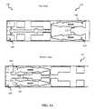
- FIG. 1illustrates top and bottom elevation views of a multiband dipole antenna structure according to a first embodiment of the invention.
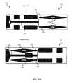
- FIG. 1Aillustrates top and bottom elevation views of a multiband dipole antenna structure according to a second embodiment of the invention.
- FIG. 1Billustrates top and bottom elevation views of a multiband dipole antenna structure according to a third embodiment of the invention.
- FIG. 1Cis a top elevation view showing a multiband dipole antenna of FIG. 1B , configured in a radome according to one embodiment of the invention.
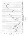
- FIG. 2is a plot of measured free space input return loss of the exemplary multiband dipole antenna of the embodiment of FIG. 1B .
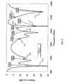
- FIG. 3is a plot of measured total efficiency of the exemplary multiband dipole antenna of the embodiment of FIG. 1B .
- FIG. 4is a plot of measured maximum antenna gain of the exemplary multiband dipole antenna of the embodiment of FIG. 1B .
- FIG. 5is a diagram illustrating an exemplary coordinate system used in radiation pattern measurements.
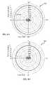
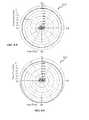
- FIGS. 8-1 through 8 - 11are plots of measured azimuth-plane (x, y) radiation pattern of the exemplary multiband dipole antenna configured in accordance with the embodiment of FIG. 1B , obtained at different frequencies of (i) 698 MHz; (ii) 859 MHz; (iii) 960 MHz, (iv) 1710 MHz, (v) 1860 MHz, (vi) 1980 MHz, (vii) 2110 MHz, (viii) 2170 MHz, (ix) 2500 MHz, (x) 2600 MHz, and (xi) 2700 MHz, respectively.
- access pointrefers without limitation to any wireless radio device capable of exchanging data via a radio link.
- the terms “antenna,” “antenna system,” “antenna assembly”, and “multi-band antenna”refer without limitation to any system that incorporates a single element, multiple elements, or one or more arrays of elements that receive/transmit and/or propagate one or more frequency bands of electromagnetic radiation.
- the radiationmay be of numerous types, e.g., microwave, millimeter wave, radio frequency, digital modulated, analog, analog/digital encoded, digitally encoded millimeter wave energy, or the like.
- a substraterefer generally and without limitation to any substantially planar or curved surface or component upon which other components can be disposed.
- a substratemay comprise a single or multi-layered printed circuit board (e.g., FR4), a semi-conductive die or wafer, or even a surface of a housing or other device component, and may be substantially rigid or alternatively at least somewhat flexible.
- frequency rangerefers without limitation to any frequency range for communicating signals. Such signals may be communicated pursuant to one or more standards or wireless air interfaces.
- the terms “portable device”, “mobile computing device”, “client device”, “portable computing device”, and “end user device”include, but are not limited to, personal computers (PCs) and minicomputers, whether desktop, laptop, or otherwise, set-top boxes, personal digital assistants (PDAs), handheld computers, personal communicators, tablet computers, portable navigation aids, J2ME equipped devices, cellular telephones, smartphones, personal integrated communication or entertainment devices, or literally any other device capable of interchanging data with a network or another device.
- PCspersonal computers
- PDAspersonal digital assistants
- handheld computerspersonal communicators
- tablet computerstablet computers
- portable navigation aidsportable navigation aids
- J2ME equipped devicesJ2ME equipped devices
- cellular telephonessmartphones
- smartphonespersonal integrated communication or entertainment devices
- the terms “radiator,” “radiating plane,” and “radiating element”refer without limitation to an element that can function as part of a system that receives and/or transmits radio-frequency electromagnetic radiation; e.g., an antenna or portion thereof.
- RF feedrefers without limitation to any energy conductor and coupling element(s) that can transfer energy, transform impedance, enhance performance characteristics, and conform impedance properties between an incoming/outgoing RF energy signals to that of one or more connective elements, such as for example a radiator.
- topAs used herein, the terms “top”, “bottom”, “side”, “up”, “down”, “left”, “right”, and the like merely connote a relative position or geometry of one component to another, and in no way connote an absolute frame of reference or any required orientation. For example, a “top” portion of a component may actually reside below a “bottom” portion when the component is mounted to another device (e.g., to the underside of a PCB).
- wirelessmeans any wireless signal, data, communication, or other interface including without limitation Wi-Fi, Bluetooth, 3G (e.g., 3GPP, 3GPP2, and UMTS), HSDPA/HSUPA, TDMA, CDMA (e.g., IS-95A, WCDMA, etc.), FHSS, DSSS, GSM, PAN/802.15, WiMAX (802.16), 802.20, narrowband/FDMA, OFDM, PCS/DCS, Long Term Evolution (LTE) or LTE-Advanced (LTE-A), analog cellular, CDPD, satellite systems such as GPS, millimeter wave or microwave systems, optical, acoustic, and infrared (i.e., IrDA).
- 3Ge.g., 3GPP, 3GPP2, and UMTS
- HSDPA/HSUPAe.g., TDMA
- CDMAe.g., IS-95A, WCDMA, etc.
- FHSSDSSS
- the present inventionprovides, in one salient aspect, a multi-band dipole antenna apparatus for use with a radio device which advantageously provides reduced size and cost, and improved antenna performance.
- the antenna apparatusincludes two separate antenna assemblies disposed on the opposing sides of a thin dielectric element.
- Each antenna assembly of the exemplary embodimentis adapted for use in LTE devices, and includes a first radiator structure configured to operate in a lower frequency band (LFB), a second radiator structure configured to operate in an upper frequency band (UFB), and an electromagnetic coupling element disposed there between.
- the first radiator structureis configured such that a higher-order resonance mode optimizes upper frequency band operation.
- the first radiator structureis galvanically coupled to a feed port of the radio device via a transmission line element.
- the second radiator structureis electromagnetically coupled to the feed via the electromagnetic coupling element, also commonly referred to as the parasitic coupling.
- the two antenna assembliesare configured in an opposing fashion such that the LFB radiator of the top antenna is positioned above the UFB radiator of the bottom antenna and the UFB radiator of the top antenna is positioned above the LFB radiator of the bottom antenna.
- Such radiator configurationenables the UFB structure of each antenna assembly (for example, on the top side) to couple to the LFB structure of the opposing antenna assembly (for example, on the bottom side) via electric field coupling at a resonance frequency across the dielectric substrate thickness.
- the transmission line of each antenna assemblyincludes, in one implementation, a linear microstrip element featuring a tuning flap structure that may be disposed at different locations along the length of the transmission line. Such configuration improves antenna feed efficiency and optimizes antenna resonance.
- each of the LFB and UFB radiator structures of the exemplary embodimentincludes a pair of radiating arms, disposed symmetrically with respect to a longitudinal axis of the dielectric element and parallel with respect to one another.
- the UFB armsare configured as elongated rhomboids and UFB arms are configured as elongated rectangular or elliptical elements.
- Such two planar blade dipole antenna assembliesprovide a combined omni-directional radiation pattern in the azimuthal plane for each of the lower and upper frequency bands.
- a linear slot(disposed axially within the LFB arm, in one implementation, is configured to improve HFB coupling.
- a single multi-feed transceiveris configured to provide feed signal to both antenna assemblies.
- the feedis effected via a coaxial cable which is coupled to a top side of the antenna apparatus.
- the antenna coupling structure(in one implementation) includes a set of conductors galvanically coupling the top side coupling point to the bottom side coupling point in order to provide feed to the second antenna assembly.
- FIGS. 1 through 1Cvarious exemplary embodiments of the radio antenna apparatus of the invention are described in detail.
- the inventionis in no way limited to planar antenna configuration, and in fact can be implemented using other shapes, such as, for example, a three-dimensional (3D) cylinder or a truncated cone.
- FIG. 1One exemplary embodiment of a multiband antenna component 100 for use with a radio device is presented in FIG. 1 , showing top and bottom elevation views of the antenna structure.
- the antenna component shown in FIG. 1includes a planar dielectric element 102 fabricated from a suitable material such as 4000-series high frequency circuit laminate manufactured by Rogers Corporation, although it will be appreciated that other materials may be used.
- the antenna 100further includes two antenna sub-assemblies 101 , 131 disposed on the top and the bottom side of the dielectric element 102 , respectively.
- the antenna structureis fabricated using a flex circuit.
- the top antenna sub-assembly 101includes a low frequency band (LFB) structure comprised of two symmetric arms 106 , each coupled to a feed 104 (here a point) via a linear transmission line element 110 , implemented as a microstrip in one variant.
- a flap 114is added to the transmission line in order to enable precise manipulation of antenna resonances, and to improve feed coupling.
- the flap 114includes a rectangular perimeter, while other shapes (such as rhomboid, circle or an ellipse) are equally compatible and useful with the invention. Furthermore, positioning the flap 114 at different locations along the transmission line 110 allows for optimization of antenna operation in different LF and HF bands.
- the feed 104 and the ground 120 coupling pointsare configured to connect the antenna component 100 via a feed cable to the device feed engine.
- the feed cableincludes a coaxial cable with a shield, and is connected to the radio device via an RF connector.
- Other 50 ohm RF transmission line configurationse.g., SMA connector, flex circuit, etc. are usable as well.
- the feed conductor of the coaxial feed cableconnects the antenna feed point 104 to the RF engine feed port, and the shield conductor is connected to the antenna ground coupling point 120 .
- the antenna ground coupling structureincludes the top ground point 120 connected to the bottom ground structure 134 through, for example, via holes that provide galvanic contact between the two ground structures ( 120 , 134 ), therefore coupling the structure 134 to the feed cable ground conductor.
- the bottom antenna sub-assembly 131similarly includes a low frequency band structure comprised of two symmetric arms 136 , each coupled to the ground structure 134 via the transmission line element 140 .
- a flap 144is added to the transmission line 140 in order to enable precise manipulation of antenna resonances, and to improve feed coupling.
- the flap 114comprises a rectangular perimeter, while other shapes (such as rhomboid, circle or an ellipse) are equally compatible and useful with the invention. Furthermore, positioning the flap 114 at different locations along the transmission line 110 allows for optimization of antenna operation in different LF and HF bands.
- Each of the top and the bottom antenna sub-assemblies 101 , 131comprises a high frequency band (HFB) radiating structure comprising a pair of arms 112 , 142 , respectively.
- the arms 112are disposed symmetrically with respect to the transmission line 110 while the arms 142 are disposed substantially symmetrically with respect to the longitudinal axis 117 of the antenna assembly.
- the HFB arms 112are electromagnetically coupled to the feed via nonconductive gaps 108 , formed between the adjacent edges of the HFB arms 112 and the transmission line 110 (and its “T” junction portion).
- the gaps 108act as electromagnetic coupling elements, providing capacitive coupling between the transmission line and the HFB arms, and enabling energy transfer from the feed.
- the HFB arms 142are electromagnetically coupled to the feed via nonconductive gaps 109 formed between the adjacent edges of the HFB arms 142 and the T-junction portion of the transmission line 110 .
- the gaps 109act as electromagnetic coupling (also referred to as the parasitic coupling) elements, enabling higher-order mode resonances in the HFB arms.
- the configuration shown in FIG. 1causes the lower band feed (for example, in the frequency range between 700 MHz and 960 MHz) to generate second-order resonance modes in the HFB arms, thereby facilitating antenna operation in a higher frequency range (for example, between 1710 and 2170 MHz).
- the second harmonic for an ideal (properly matched) single frequency oscillator of 960 MHzcorresponds to 1920 MHz
- the wide span of the low frequency range (700-960 MHz)enables efficient antenna operation at frequencies of up to 2170 MHz in the HFB.
- the LFB 106 , 142 and the HFB 112 , 136 radiating structuresare disposed opposing each other on the top 101 and the bottom 131 antenna sub-assemblies, respectively. That is, the LFB structure 106 is disposed above the HFB structure 142 , while the HFB structure 112 is disposed above the LFB structure 136 .
- This “head-to-toe” configurationfurther enables coupling of the HFB structures 112 , 142 to the respective LFB structures 106 , 136 , respectively, via electric field at the resonance across the thickness of the dielectric substrate 102 .
- the electromagnetic and electric field coupling described aboveis also commonly referred to as “parasitic coupling”, and the antenna elements that are fed in such manner are commonly referred to as “parasitics”.
- Each of the LFB arms 106 , 136 of the antenna embodiment of FIG. 1comprises a linear slot 116 disposed axially proximate the center axis of the respective arm, so as to improve electromagnetic coupling efficiency of the respective HFB arm (that is the arms 142 , 112 , respectively) disposed underneath the LFB arms 106 , 146 .
- the antenna sub-assemblies 101 , 131comprise a second set of lower band parasitically coupled radiator arms 118 , 148 configured opposite from the LFB respective structures. That is, the parasitic LFB structure 118 of the top sub-assembly 101 is disposed above the LFB structure 136 of the bottom sub-assembly 131 , and the parasitic LFB structure 148 of the bottom sub-assembly 131 is disposed above the LFB structure 106 of the top sub-assembly 101 , respectively.
- Such antenna sub-assembly configurationcauses electromagnetic coupling between the parasitic LFB structures 118 , 148 and the directly-fed LFB structures 106 , 136 , respectively, thereby enabling antenna matching over a wider frequency band.
- This approachadvantageously increases useful frequency range of the antenna apparatus shown in FIG. 1 , and enables radio device operation in additional frequency bands (e.g., LTE bands).
- each of the structures 106 , 112 , 118 , 136 , 142 , 148are configured with regard to a specific design requirements such as available space, bandwidth, efficiency, radiation pattern, and power.
- the exemplary antenna of the embodiment presented in FIG. 1is configured to operate in the following long-term evolution (LTE)/LTE-A system frequency bands of approximately 698-960 MHz, 1710-1990 MHz, 2110-2170 MHz, and 2500-2700 MHz.
- LTElong-term evolution
- LTE-A system frequency bandsof approximately 698-960 MHz, 1710-1990 MHz, 2110-2170 MHz, and 2500-2700 MHz.
- the exemplary antennais approximately 165 mm (6.56 inch) in length, 28 mm (1.1 inch) in width, and 0.9 mm (0.032 inch) thick.
- the antenna widthis reduced to 25 mm (1 inch) or 20 mm (0.79 inch), while keeping the same length and thickness.
- WWANwireless wide area network
- WiMAX2.3 and 2.5 GHz
- the directly-fed LFB antenna arms ( 106 , 136 ) of the exemplary embodimentare configured as substantially diamond-shaped elongated polygons. That is, the width of each of the arms 106 , 136 is smaller than the length.
- one end of each armfeatures a tuning element 122 , 150 , and the other end ( 128 ) is truncated to effect precise antenna tuning to the desired bands of operation.
- the radiator arm diamond shapeprovides good electromagnetic coupling to the HFB arms, and produces a wide band response in the lower frequency band.
- FIG. 1AAnother exemplary embodiment of the dipole antenna according to the present invention is shown in FIG. 1A .
- the antenna component 158 of this embodimentincludes a top sub-assembly 159 and a bottom sub-assembly 161 , each configured similarly to the antenna sub-assemblies 101 , 131 of the device of FIG. 1 described supra.
- one end of each arm of the directly-fed LFB structure 162 , 166features a triangular-shaped tuning element (similar to the element 122 of the embodiment of FIG. 1 ), and the opposing end of the arm features a trapezoidal-shaped tuning element 168 , each configured to effect antenna tuning to the desired bands of operation.
- each arm 174 , 176 of the direct-fed LFB structuresis shaped as a rhomboid with a triangular-shaped tuning element 178 (similar yet smaller compared to the element 122 of the embodiment of FIG. 1 ) disposed on one end, that is proximate to the direct connection to the transmission lines 110 , 140 .
- FIG. 1CAn embodiment of the antenna apparatus, comprising multiband dipole antenna components (such as shown and described with respect to FIGS. 1-1B , supra) is presented in FIG. 1C in the form of a “radome”.
- the antenna apparatus 180 of FIG. 1Cincludes the antenna component (such as, for example, the component 170 of FIG. 1B ) encapsulated in a radome structure 182 .
- the top antenna sub-assembly 171 of FIG. 1Bis shown in white, and portions of the bottom antenna sub-assembly 172 of FIG. 1B are shown in black in FIG. 1C .
- One end of the antenna apparatus 180features a mounting flange 184 , which is used to attach the antenna during operation and to route a feed cable 186 .
- the radome structure 182is preferably fabricated using thermoplastic materials such as e.g., polycarbonate (PC), or Acrylonitrile Butadiene Styrene (ABS).
- PCpolycarbonate
- ABSAcrylonitrile Butadiene Styrene
- the radome 182provides mechanical support for the antenna radiating elements and protection from the elements during use. As the radome 182 affects RF field distribution and antenna resonance frequency, tuning of the antenna assembly (that uses the exact radome structure of the final product) is required.
- antenna feed couplingsare disposed proximate one lateral edge of the dielectric substrate.
- both coupling structures(such as the feed point 104 and the ground coupling point 120 ) are disposed on the same side of the substrate.
- Such coupling configurationsimplifies attachment of the RF feed cable to the antenna sub-assemblies, and optimizes antenna resonances with different connector types.
- the feed cableis attached to the dipole antenna component using an RF connector, or a mechanical friction joint (crimp, push and lock), or any other suitable technology.
- the exemplary antenna embodiments shown and described with respect to FIGS. 1-1C , supra,utilize a single feed antenna configuration such that the antenna radiators of one band (for example the lower band) are fed directly via a feed strip (the transmission line 110 ), and the antenna radiators of a second bands (HFB) are fed by way of electromagnetic coupling.
- the top antenna sub-assembly(such as, for example, the sub-assembly 101 of FIG. 1 ) is connected to the feed conductor of the radio device and acts as one arm of the dipole, while the bottom antenna sub-assembly (such as, for example, the sub-assembly 131 of FIG. 1 ) is connected to the ground conductor, and acts as a ground base arm of the dipole.
- the exemplary antenna configuration(such as that shown in FIG. 1 ) includes two side-by-side dipoles in a vertical plane that are combined by the transmission line ( 110 ), thus providing the desired omni-directional antenna radiation pattern in azimuthal plane, as illustrated by the antenna performance results described below.
- FIGS. 2 through 8 - 11performance results obtained during testing by the Assignee hereof of an exemplary antenna apparatus constructed according to the invention are presented.
- FIG. 2shows a plot of free-space return loss S 11 (in dB) as a function of frequency, measured with a single-feed dipole antenna component constructed in accordance with the embodiment shown and described with respect to FIG. 1B , supra,
- the return loss dataclearly show the exemplary antenna comprising several distinct frequency bands from 600 MHz to 2700 MHz.
- the designators 202 - 216mark the frequencies 698 MHz, 960 MHz, 1710 MHz, 1990 MHz, 2110 MHz, 2170 MHz, 2500 MHz, and 2700 MHz, respectively.
- FIG. 3presents data regarding measured free-space efficiency for the same antenna configuration (i.e., that of FIG. 1B ).
- Antenna efficiency (in dB)is defined as decimal logarithm of a ratio of radiated and input power:
- AntennaEfficiency ⁇ [ dB ] ⁇ 10 ⁇ ⁇ log 10 ⁇ ( Radiated ⁇ ⁇ Power Input ⁇ ⁇ Power ) Eqn . ⁇ ( 1 ) while antenna efficiency (in %)is defined as follows:
- AntennaEfficiency ⁇ [ % ]100 ⁇ ( Radiated ⁇ ⁇ Power Input ⁇ ⁇ Power ) Eqn . ⁇ ( 2 )
- An efficiency of zero (0) dB or 100%corresponds to an ideal theoretical radiator, wherein all of the input power is radiated in the form of electromagnetic energy.
- the data in FIG. 3shown both in dB (solid line) and in % (vertical bars), are collected in the following frequency bands: (i) the lower band 698-960 MHz; (ii) the first upper band 1710-1980 MHz; (iii) the second upper band 2110-2170 MHz, and (iv) the third upper band 2500-2700 MHz, denoted with the designators 302 - 308 , respectively.
- the data of FIG. 3demonstrate LFB efficiency between 65% and 90% in a lower portion of the lower band, decreasing to 40% level at the upper edge of the LFB.
- the first upper band ( 304 ) efficiencyis above 60% throughout the band, and the second upper band has efficiency between 35% and 70%.
- the third upper band 308shows efficiency in a range between 30% and 70%.
- FIG. 4presents data regarding measured maximum antenna gain obtained with the same antenna configuration ( FIG. 1B ).
- the data in FIG. 4confirm antenna gain between ⁇ 0.5 and 3 dB in the LFB, 0 to 4 dB in the first upper band, and 4 to 6 dB in the second upper band.
- FIGS. 5 through 8 - 11present data related to measured radiating pattern of the exemplary multiband dipole antenna configured in accordance with the embodiment of FIG. 1B .
- FIG. 5illustrates an exemplary coordinate system and definitions useful for interpreting the radiating patterns of FIGS. 6-1 through 8 - 11 .
- ⁇is the elevation angle
- ⁇is the azimuth angle
- the azimuth plane radiation patternsare obtained with measurements made while traversing the entire x-y plane around the antenna under test.
- the elevation plane in FIG. 5is defined as a plane orthogonal to the x-y plane.
- the elevation plane patternsare obtained traversing the entire y-z plane around the antenna under test. The above definitions are used in describing exemplary antenna radiation patterns with respect to FIGS. 6-8 , described below.
- Different radiation pattern plotsdenoted by the designators 602 - 622 , correspond to the frequencies of antenna operation of: (i) 698 MHz; (ii) 859 MHz; (iii) 960 MHz, (iv) 1710 MHz, (v) 1860 MHz, (vi) 1980 MHz, (vii) 2110 MHz, (viii) 2170 MHz, (ix) 2500 MHz, (x) 2600 MHz, and (xi) 2700 MHz, respectively.
- Measurements obtained at different frequencies ofare denoted by the designators 702 - 720 , respectively.
- the radiation patterns 602 - 616 of FIGS. 6-1 through 6 - 11 and 702 - 716 of FIGS. 7-1 through 7 - 10demonstrate a typical dipole antenna radiation pattern, with the maximum power achieved at elevation angles of 90 and 270 deg, as expected. While the radiation patterns 618 - 622 and 718 - 720 obtained at the highest frequencies (2500 MHz, 2600 MHz, and 2700 MHz, respectively) show noticeable deviations from the dipole behavior, they provide sufficient performance in most typical operational conditions.
- FIGS. 8-1 through 8 - 11are plots of measured azimuth-plane (x, y) radiation pattern of the exemplary multiband dipole antenna configured in accordance with the embodiment of FIG. 1B obtained at frequencies of (i) 698 MHz; (ii) 859 MHz; (iii) 960 MHz, (iv) 1710 MHz, (v) 1860 MHz, (vi) 1980 MHz, (vii) 2110 MHz, (viii) 2170 MHz, (ix) 2500 MHz, (x) 2600 MHz, and (xi) 2700 MHz, as denoted by the designators 802 - 824 , respectively.
- the data presented in FIGS. 8-1 through 8 - 11demonstrate excellent omni-directional antenna performance extending throughout the high frequencies, including 2700 MHz.
- FIGS. 2-4 and FIGS. 6-1 through 8 - 11confirm that a single planar dipole antenna, configured in accordance with the invention, is capable of efficient operation in the LTE frequency ranges of 698-960 MHz, 1710-1980 MHz, 2110-2170 MHz, and 2500-2690 MHz, providing omni-directional radiation with a gain of 2 dBi, a level of performance that is unattainable with prior art single-feed dipole antenna solutions.
- Such capability provided by the present inventionadvantageously allows operation of a radio frequency device (such as a corporate wireless access point, wireless bridge or a wireless hub) with a single antenna over several mobile frequency bands such as GSM710, GSM750, GSM850, E-GSM900 GSM810, GSM1900, GSM1800, PCS-1900, as well as LTE/LTE-A and WiMAX (IEEE Std. 802.16) frequency bands.
- LTE/LTE-A and WiMAXIEEE Std. 802.16
- the frequency band composition given abovemay be modified as required by the particular bands of the application(s), and additional bands may be supported/used as well.
- the electrical dimensions of an antenna configured in accordance with the inventioncan be scaled (up or down)
- the corresponding operating frequency bandsare scaled down by the same factor producing an antenna operating in a frequency range from about 350 MHz to about 1350 MHz.
- an antenna that is half the size of the antenna of FIG. 1Bwill operate in a frequency range from about 1400 MHz to about 5400 MHz.
- an antenna apparatus configurationcomprising planar dipole antenna components as in the illustrated embodiments described herein allows for optimization of antenna operation in the lower frequency band simultaneously with the upper band operation.
- This antenna solutionallows for, inter aria, a single standards-compliant (e.g., LTE-compliant) wireless device (such as a corporate access point, and back up for wireless link for data service) to cover several relevant frequency bands, while maintaining an improved dipole-type radiation pattern for most of the frequency range.
- 4Gfourth generation wireless
- the use of the exemplary single-feed configurationsimplifies antenna connections, and allows for a smaller and less complicated design of the device RF feed electronics.
- an external antennais employed to establish a small corporate access point and a backup wireless link for data service, and to serve established external antenna demand in LTE applications.
Landscapes
- Engineering & Computer Science (AREA)
- Computer Networks & Wireless Communication (AREA)
- Variable-Direction Aerials And Aerial Arrays (AREA)
- Waveguide Aerials (AREA)
- Details Of Aerials (AREA)
Abstract
Description
A portion of the disclosure of this patent document contains material that is subject to copyright protection. The copyright owner has no objection to the facsimile reproduction by anyone of the patent document or the patent disclosure, as it appears in the Patent and Trademark Office patent files or records, but otherwise reserves all copyright rights whatsoever.
The present invention relates generally to antenna apparatus for use within electronic devices such as wireless radio devices, and more particularly in one exemplary aspect to a multi-band long term evolution (LTE) antenna, and methods of tuning and utilizing the same.
Increased proliferation of long term evolution and long term evolution advanced (hereinafter collectively “LTE”) mobile data services creates an increased demand for compact multi-band antennas typically used in radio devices, such as wireless access point, bridge, or a hub. Typically, it is desired for an LTE-compliant radio device to support operation in multiple frequency bands (such as, for example, 698 MHz to 960 MHz, 1710 MHz to 1990 MHz, 2110 MHz to 2170 MHz, and 2500 MHz to 2700 MHz). Furthermore, LTE system has been defined to accommodate paired spectrum for Frequency Division Duplex (FDD) mode of operation where the uplink and the downlink transmissions occupy different parts of the spectrum. By way of example, the uplink occupies the frequency range from 1710 MHz to 1770 MHz, and the downlink occupies the frequency range from 2110 MHz to 2170 MHz. It is therefore desirable for antennas used in an LTE-compliant device to cover a wide range of frequencies ranging from about 650 MHz to about 2700 MHz, while maintaining a unidirectional radiation pattern. It is further desired to be able to tune individual operating frequency bands of the antenna without affecting antenna functionality in other bands.
Dipole type antennas are typically used to achieve an omni-directional radiation pattern, such as characterized by radiation pattern that is shaped like a toroid in three-dimensional space and is symmetric about the axis of the dipole.
However, most existing single feed dipole antenna solutions operate in a single frequency band. At present, implementing a single planar dipole antenna that is efficient in several frequency bands is problematic, as separate antenna elements that cover different frequency bands interact with each other and create mutual interference patterns that degrade antenna performance. Some existing approaches attempt to solve this problem by constructing multiple separately fed dipole antennas, each cooperating in a separate frequency band. Multiple dipole antennas (packaged within the same protective enclosure, also referred to as the radome) are often used to achieve multiband operation. However, such solutions require a separate feed for each antenna thereby increasing cost and complexity. This approach may also cause coupled resonances that adversely affect antenna performance.
Accordingly, there is a salient need for an improved multiband dipole antenna solution suitable for use in, inter alia, LTE compliant radio devices, that offers a lower cost and complexity, and provides for improved control of antenna resonance. Such improved solution would also ideally have a desirable form factor (e.g., small size, and compatible with target applications such as hand-held mobile devices).
The present invention satisfies the foregoing needs by providing, inter alia, a space-efficient multiband antenna apparatus, and methods of tuning and use.
In a first aspect of the invention, an antenna apparatus operable in a first frequency band and a second frequency band is disclosed. In one embodiment, the antenna apparatus includes a dielectric element comprising a first side and a second side, a feed point disposed on the first side, and a ground point disposed on the second side, a first structure operable in the first frequency band and disposed substantially on the first side, a second structure operable in the first frequency band and disposed substantially on the second side, a third structure operable in the second frequency band and disposed substantially on the first side, and a fourth structure operable in the second frequency band and disposed substantially on the second side. In one variant, the first structure is galvanically coupled to the feed point, the second structure is galvanically coupled to the ground point, the third structure is configured to electromagnetically couple to the first structure, and the fourth structure is configured to electromagnetically coupled to the second structure.
In another variant, the first structure includes a first radiator arm disposed substantially co-planar yet parallel to a second radiator arm and the second structure includes a third radiator arm disposed substantially co-planar yet parallel to a fourth radiator arm, the first radiator arm and the second radiator arm each comprise a linear slot disposed substantially longitudinally within the respective aim, and the apparatus includes a first substantially linear conductive element disposed on the first side and configured to couple the feed point to the first and the second radiator arms via a first T-junction, and a second substantially linear conductive element disposed on the second side and configured to couple the feed point to the third and the fourth radiator arms via a second T-junction.
In another variant, the antenna apparatus includes a first conductive element disposed between the first structure and the feed point and effecting the galvanic coupling to the feed point, a first electromagnetic coupling element electrically disposed between the first conductive element and a first branch of the third structure, and a second electromagnetic coupling element electrically disposed between the first conductive element and a second branch of the third structure, so that the first electromagnetic coupling element is configured to electromagnetically couple the first branch of the third structure to the feed point, and the second electromagnetic coupling element is configured to electromagnetically couple the second branch of the third structure to the feed point.
In yet another variant, the antenna apparatus includes a second conductive element disposed between at least a portion of the second structure and the ground point and effecting the galvanic coupling to the ground point, a third electromagnetic coupling element electrically disposed between at least a portion of the second conductive element and a first branch of the fourth structure, and a fourth electromagnetic coupling element electrically disposed between at least a portion of the second conductive element and a second branch of the fourth structure, the third electromagnetic coupling element is configured to electromagnetically couple the first branch of the fourth structure to the ground point, and the fourth electromagnetic coupling element is configured to electromagnetically couple the second branch of the fourth structure to the ground point.
In still another variant, the antenna apparatus includes a structure disposed substantially on the first side and configured to electrically couple to the second conductive element, so that electric coupling of the structure to the second conductive element is effected via a conductor configured to penetrate through the dielectric element in a direction normal to the first side.
In another variant, the first structure and the second structure are configured to cooperate to form at least a portion of a first dipole antenna operable in the first frequency band, and the third structure and the fourth structure are configured to cooperate to form at least a portion of a second dipole antenna operable in the second frequency band so that the antenna apparatus is characterized by a substantially omni-directional radiation pattern in at least one of the first frequency band and the second frequency band in a plane substantially normal to the element, and the first frequency band includes a lower frequency long term evolution (LTE) application band, and the second frequency band includes an upper frequency LTE application band.
In another aspect of the invention, a multiband antenna component for use with a radio communications device, the device operable in a first frequency band and a second frequency band is disclosed. In one embodiment, the antenna component includes a dielectric element comprising a first side and a second side, a first structure operable in the first frequency band and disposed substantially on the first side, a second structure operable in the first frequency band and disposed substantially on the second side, the first structure is connected to a feed disposed on the first side, and the second structure is connected to a coupling.
In one variant, antenna component includes a third structure operable in the second frequency band and disposed substantially on the first side, and a fourth structure operable in the second frequency band and disposed substantially on the second side, the third structure is configured to electromagnetically couple to the first structure, the fourth structure is configured to electromagnetically couple to the second structure, the first frequency band includes a lower frequency long term evolution (LTE) application band and second frequency band is selected from a group consisting of (i) 1710-1990 MHz, (ii) 2110-2170 MHz; and 2500-2700 MHz long term evolution (LIE) application frequency bands.
In another variant, the first structure includes a first radiator arm disposed substantially co-planar yet parallel to a second radiator arm, the first radiator arm includes a first linear slot disposed substantially longitudinally within the first radiator arm, the second structure includes a third radiator arm disposed substantially co-planar yet parallel to a fourth radiator arm, and the second radiator arm includes a second linear slot disposed substantially longitudinally within the second radiator arm, a first conductive element disposed between the first structure and the feed and effecting the connection of the first structure to the feed.
In another variant, the antenna component includes a first electromagnetic coupling element electrically disposed between the first conductive element and a first branch of the third structure, and a second electromagnetic coupling element electrically disposed between the first conductive element and a second branch of the third structure, the first electromagnetic coupling element is configured to electromagnetically couple the first radiator arm to the feed point, and the second electromagnetic coupling element is configured to electromagnetically couple the second radiator arm to the feed.
In yet another variant, the antenna component includes a first conductive element disposed on the first side and configured to effect the connection between the feed and the first structure, a second conductive element disposed on the second side and configured to effect the connection between the coupling and the second structure, and a structure disposed substantially on the first side and configured to electrically couple to the second conductive element.
In still another variant, outer perimeter of the first structure is configured substantially external to outer perimeter of the second structure, outer perimeter of the third structure is configured substantially external to outer perimeter of the fourth structure, outer perimeter of the first structure is configured to overlap at least partially outer perimeter of the third structure when viewed in a direction substantially normal to the first side, and outer perimeter of the second structure is configured to overlap at least partially outer perimeter of the fourth structure when viewed in the direction substantially normal to the first side.
In a third aspect of the invention, a method of operating an antenna apparatus is disclosed. In one embodiment, the method comprises providing a feed signal to both a feed disposed on a first side of a dielectric substrate, and to a coupling disposed on the second side of the dielectric substrate; exciting a first antenna structure disposed substantially on the first side and electrically coupled to the feed point so as to radiate in a first frequency band; and exciting a second antenna structure disposed substantially on the second side so as to radiate in the first frequency band.
In a fourth aspect of the invention, a method of tuning an antenna apparatus is disclosed. In one embodiment, the method comprises providing a feed signal to both a feed disposed on a first side of a dielectric substrate, and to a coupling disposed on the second side of the dielectric substrate; exciting a first antenna structure disposed substantially on the first side and electrically coupled to the feed so as to radiate in a first frequency band, and exciting a second antenna structure disposed substantially on the second side so as to radiate in the first frequency band, and tuning an electromagnetic coupling of a third antenna structure and the first antenna structure in a second frequency band. In one variant, the electromagnetic coupling of the third antenna structure and the first antenna structure is effected by a first linear slot disposed substantially longitudinally within a first radiator arm, and a second linear slot disposed substantially longitudinally within a second radiator arm.
In a fifth aspect of the invention, a method of operating a mobile device is disclosed. In one embodiment, the method comprises providing a feed signal to both an antenna feed disposed on a first side of a dielectric substrate, and to an antenna coupling disposed on the second side of the dielectric substrate; exciting a first antenna structure disposed substantially on the first side and electrically coupled to the feed so as to radiate in the first frequency band; and exciting a second antenna structure disposed substantially on the second side to radiate in the first frequency band.
Further features of the present invention, its nature and various advantages will be more apparent from the accompanying drawings and the following detailed description.
The features, objectives, and advantages of the invention will become more apparent from the detailed description set forth below when taken in conjunction with the drawings, wherein:
All Figures disclosed herein are © Copyright 2011 Pulse Finland Oy. All rights reserved.
Reference is now made to the drawings wherein like numerals refer to like parts throughout.
As used herein, the terms “access point,” “wireless hub,” “wireless bridge”, ‘wireless station”, and “corporate access point” refer without limitation to any wireless radio device capable of exchanging data via a radio link.
As used herein, the terms “antenna,” “antenna system,” “antenna assembly”, and “multi-band antenna” refer without limitation to any system that incorporates a single element, multiple elements, or one or more arrays of elements that receive/transmit and/or propagate one or more frequency bands of electromagnetic radiation. The radiation may be of numerous types, e.g., microwave, millimeter wave, radio frequency, digital modulated, analog, analog/digital encoded, digitally encoded millimeter wave energy, or the like.
As used herein, the terms “board” and “substrate” refer generally and without limitation to any substantially planar or curved surface or component upon which other components can be disposed. For example, a substrate may comprise a single or multi-layered printed circuit board (e.g., FR4), a semi-conductive die or wafer, or even a surface of a housing or other device component, and may be substantially rigid or alternatively at least somewhat flexible.
The terms “frequency range”, “frequency band”, and “frequency domain” refer without limitation to any frequency range for communicating signals. Such signals may be communicated pursuant to one or more standards or wireless air interfaces.
As used herein, the terms “portable device”, “mobile computing device”, “client device”, “portable computing device”, and “end user device” include, but are not limited to, personal computers (PCs) and minicomputers, whether desktop, laptop, or otherwise, set-top boxes, personal digital assistants (PDAs), handheld computers, personal communicators, tablet computers, portable navigation aids, J2ME equipped devices, cellular telephones, smartphones, personal integrated communication or entertainment devices, or literally any other device capable of interchanging data with a network or another device.
Furthermore, as used herein, the terms “radiator,” “radiating plane,” and “radiating element” refer without limitation to an element that can function as part of a system that receives and/or transmits radio-frequency electromagnetic radiation; e.g., an antenna or portion thereof.
The terms “RF feed,” “feed,” “feed conductor,” and “feed network” refer without limitation to any energy conductor and coupling element(s) that can transfer energy, transform impedance, enhance performance characteristics, and conform impedance properties between an incoming/outgoing RF energy signals to that of one or more connective elements, such as for example a radiator.
As used herein, the terms “top”, “bottom”, “side”, “up”, “down”, “left”, “right”, and the like merely connote a relative position or geometry of one component to another, and in no way connote an absolute frame of reference or any required orientation. For example, a “top” portion of a component may actually reside below a “bottom” portion when the component is mounted to another device (e.g., to the underside of a PCB).
As used herein, the term “wireless” means any wireless signal, data, communication, or other interface including without limitation Wi-Fi, Bluetooth, 3G (e.g., 3GPP, 3GPP2, and UMTS), HSDPA/HSUPA, TDMA, CDMA (e.g., IS-95A, WCDMA, etc.), FHSS, DSSS, GSM, PAN/802.15, WiMAX (802.16), 802.20, narrowband/FDMA, OFDM, PCS/DCS, Long Term Evolution (LTE) or LTE-Advanced (LTE-A), analog cellular, CDPD, satellite systems such as GPS, millimeter wave or microwave systems, optical, acoustic, and infrared (i.e., IrDA).
Overview
The present invention provides, in one salient aspect, a multi-band dipole antenna apparatus for use with a radio device which advantageously provides reduced size and cost, and improved antenna performance. In one embodiment, the antenna apparatus includes two separate antenna assemblies disposed on the opposing sides of a thin dielectric element.
Each antenna assembly of the exemplary embodiment is adapted for use in LTE devices, and includes a first radiator structure configured to operate in a lower frequency band (LFB), a second radiator structure configured to operate in an upper frequency band (UFB), and an electromagnetic coupling element disposed there between. The first radiator structure is configured such that a higher-order resonance mode optimizes upper frequency band operation. The first radiator structure is galvanically coupled to a feed port of the radio device via a transmission line element. The second radiator structure is electromagnetically coupled to the feed via the electromagnetic coupling element, also commonly referred to as the parasitic coupling. The two antenna assemblies are configured in an opposing fashion such that the LFB radiator of the top antenna is positioned above the UFB radiator of the bottom antenna and the UFB radiator of the top antenna is positioned above the LFB radiator of the bottom antenna. Such radiator configuration enables the UFB structure of each antenna assembly (for example, on the top side) to couple to the LFB structure of the opposing antenna assembly (for example, on the bottom side) via electric field coupling at a resonance frequency across the dielectric substrate thickness.
The transmission line of each antenna assembly includes, in one implementation, a linear microstrip element featuring a tuning flap structure that may be disposed at different locations along the length of the transmission line. Such configuration improves antenna feed efficiency and optimizes antenna resonance.
In order to obtain dipole radiation pattern, each of the LFB and UFB radiator structures of the exemplary embodiment includes a pair of radiating arms, disposed symmetrically with respect to a longitudinal axis of the dielectric element and parallel with respect to one another. In one variant, the UFB arms are configured as elongated rhomboids and UFB arms are configured as elongated rectangular or elliptical elements. Such two planar blade dipole antenna assemblies provide a combined omni-directional radiation pattern in the azimuthal plane for each of the lower and upper frequency bands. A linear slot (disposed axially within the LFB arm, in one implementation, is configured to improve HFB coupling.
A single multi-feed transceiver is configured to provide feed signal to both antenna assemblies. In one approach, the feed is effected via a coaxial cable which is coupled to a top side of the antenna apparatus. The antenna coupling structure (in one implementation) includes a set of conductors galvanically coupling the top side coupling point to the bottom side coupling point in order to provide feed to the second antenna assembly.
Detailed descriptions of the various embodiments and variants of the apparatus and methods of the invention are now provided. While primarily discussed in the context of the access point radio devices useful with an LTE wireless communications device or system, the various apparatus and methodologies discussed herein are not so limited. In fact, many of the apparatus and methodologies described herein are useful in any number of complex antennas, whether associated with mobile or fixed devices, cellular or otherwise, that can benefit from the multiband dipole antenna methodologies and apparatus described herein.
Exemplary Antenna Apparatus
Referring now toFIGS. 1 through 1C , various exemplary embodiments of the radio antenna apparatus of the invention are described in detail.
It will be appreciated that while these exemplary embodiments of the antenna apparatus of the invention are implemented using a blade dipole (using two surface of a planar substrate) antenna (selected in these embodiments for their desirable attributes and performance), the invention is in no way limited to planar antenna configuration, and in fact can be implemented using other shapes, such as, for example, a three-dimensional (3D) cylinder or a truncated cone.
One exemplary embodiment of amultiband antenna component 100 for use with a radio device is presented inFIG. 1 , showing top and bottom elevation views of the antenna structure. The antenna component shown inFIG. 1 includes a planardielectric element 102 fabricated from a suitable material such as 4000-series high frequency circuit laminate manufactured by Rogers Corporation, although it will be appreciated that other materials may be used. Theantenna 100 further includes twoantenna sub-assemblies dielectric element 102, respectively. In another embodiment (not shown), the antenna structure is fabricated using a flex circuit.
Thetop antenna sub-assembly 101 includes a low frequency band (LFB) structure comprised of twosymmetric arms 106, each coupled to a feed104 (here a point) via a lineartransmission line element 110, implemented as a microstrip in one variant. In another variant, aflap 114 is added to the transmission line in order to enable precise manipulation of antenna resonances, and to improve feed coupling. In one approach, theflap 114 includes a rectangular perimeter, while other shapes (such as rhomboid, circle or an ellipse) are equally compatible and useful with the invention. Furthermore, positioning theflap 114 at different locations along thetransmission line 110 allows for optimization of antenna operation in different LF and HF bands.
Thefeed 104 and theground 120 coupling points are configured to connect theantenna component 100 via a feed cable to the device feed engine. In one implementation, the feed cable includes a coaxial cable with a shield, and is connected to the radio device via an RF connector. Other 50 ohm RF transmission line configurations, e.g., SMA connector, flex circuit, etc. are usable as well. The feed conductor of the coaxial feed cable connects theantenna feed point 104 to the RF engine feed port, and the shield conductor is connected to the antennaground coupling point 120. The antenna ground coupling structure includes thetop ground point 120 connected to thebottom ground structure 134 through, for example, via holes that provide galvanic contact between the two ground structures (120,134), therefore coupling thestructure 134 to the feed cable ground conductor.
Thebottom antenna sub-assembly 131 similarly includes a low frequency band structure comprised of twosymmetric arms 136, each coupled to theground structure 134 via thetransmission line element 140. In one variant, aflap 144 is added to thetransmission line 140 in order to enable precise manipulation of antenna resonances, and to improve feed coupling. In one approach, theflap 114 comprises a rectangular perimeter, while other shapes (such as rhomboid, circle or an ellipse) are equally compatible and useful with the invention. Furthermore, positioning theflap 114 at different locations along thetransmission line 110 allows for optimization of antenna operation in different LF and HF bands.
Each of the top and thebottom antenna sub-assemblies arms arms 112 are disposed symmetrically with respect to thetransmission line 110 while thearms 142 are disposed substantially symmetrically with respect to thelongitudinal axis 117 of the antenna assembly. TheHFB arms 112 are electromagnetically coupled to the feed vianonconductive gaps 108, formed between the adjacent edges of theHFB arms 112 and the transmission line110 (and its “T” junction portion). Thegaps 108 act as electromagnetic coupling elements, providing capacitive coupling between the transmission line and the HFB arms, and enabling energy transfer from the feed.
Similarly, theHFB arms 142 are electromagnetically coupled to the feed vianonconductive gaps 109 formed between the adjacent edges of theHFB arms 142 and the T-junction portion of thetransmission line 110. Thegaps 109 act as electromagnetic coupling (also referred to as the parasitic coupling) elements, enabling higher-order mode resonances in the HFB arms. The configuration shown inFIG. 1 causes the lower band feed (for example, in the frequency range between 700 MHz and 960 MHz) to generate second-order resonance modes in the HFB arms, thereby facilitating antenna operation in a higher frequency range (for example, between 1710 and 2170 MHz). Note, although the second harmonic for an ideal (properly matched) single frequency oscillator of 960 MHz corresponds to 1920 MHz, the wide span of the low frequency range (700-960 MHz) enables efficient antenna operation at frequencies of up to 2170 MHz in the HFB.
As shown and described with respect toFIG. 1 , theLFB HFB LFB structure 106 is disposed above theHFB structure 142, while theHFB structure 112 is disposed above theLFB structure 136. This “head-to-toe” configuration further enables coupling of theHFB structures respective LFB structures dielectric substrate 102. The electromagnetic and electric field coupling described above is also commonly referred to as “parasitic coupling”, and the antenna elements that are fed in such manner are commonly referred to as “parasitics”.
Each of theLFB arms FIG. 1 comprises alinear slot 116 disposed axially proximate the center axis of the respective arm, so as to improve electromagnetic coupling efficiency of the respective HFB arm (that is thearms LFB arms
In the embodiment ofFIG. 1 , In order to increase antenna bandwidth, theantenna sub-assemblies radiator arms parasitic LFB structure 118 of thetop sub-assembly 101 is disposed above theLFB structure 136 of thebottom sub-assembly 131, and theparasitic LFB structure 148 of thebottom sub-assembly 131 is disposed above theLFB structure 106 of thetop sub-assembly 101, respectively. Such antenna sub-assembly configuration causes electromagnetic coupling between theparasitic LFB structures LFB structures FIG. 1 , and enables radio device operation in additional frequency bands (e.g., LTE bands).
The exact location and the shapes of each of thestructures FIG. 1 is configured to operate in the following long-term evolution (LTE)/LTE-A system frequency bands of approximately 698-960 MHz, 1710-1990 MHz, 2110-2170 MHz, and 2500-2700 MHz. In the antenna variant shown inFIG. 1 , the exemplary antenna is approximately 165 mm (6.56 inch) in length, 28 mm (1.1 inch) in width, and 0.9 mm (0.032 inch) thick. In other variants (not shown), the antenna width is reduced to 25 mm (1 inch) or 20 mm (0.79 inch), while keeping the same length and thickness.
Other embodiments of the invention configure the antenna apparatus to cover WWAN (e.g., 824 MHz-960 MHz, and 1710 MHz-2170 MHz), and/or WiMAX (2.3 and 2.5 GHz) frequency bands. Yet other frequency bands may be achieved as desired, using variations in the configuration of the apparatus.
The directly-fed LFB antenna arms (106,136) of the exemplary embodiment are configured as substantially diamond-shaped elongated polygons. That is, the width of each of thearms FIG. 1 , one end of each arm features atuning element
Another exemplary embodiment of the dipole antenna according to the present invention is shown inFIG. 1A . Theantenna component 158 of this embodiment includes atop sub-assembly 159 and abottom sub-assembly 161, each configured similarly to theantenna sub-assemblies FIG. 1 described supra. In the embodiment ofFIG. 1A , one end of each arm of the directly-fedLFB structure element 122 of the embodiment ofFIG. 1 ), and the opposing end of the arm features a trapezoidal-shapedtuning element 168, each configured to effect antenna tuning to the desired bands of operation.
It is appreciated by those skilled in the art that a multitude of other antenna radiating structures are equally compatible and useful with the present invention such as, inter alia, the LFB radiators shaped as shown in the antenna embodiment ofFIG. 1B . Theantenna component 170 of this embodiment includes atop sub-assembly 171 and thebottom sub-assembly 172, each configured similarly to theantenna sub-assemblies FIG. 1 described supra. In the embodiment ofFIG. 1B , eacharm element 122 of the embodiment ofFIG. 1 ) disposed on one end, that is proximate to the direct connection to thetransmission lines
An embodiment of the antenna apparatus, comprising multiband dipole antenna components (such as shown and described with respect toFIGS. 1-1B , supra) is presented inFIG. 1C in the form of a “radome”. Theantenna apparatus 180 ofFIG. 1C includes the antenna component (such as, for example, thecomponent 170 ofFIG. 1B ) encapsulated in aradome structure 182. Thetop antenna sub-assembly 171 ofFIG. 1B is shown in white, and portions of thebottom antenna sub-assembly 172 ofFIG. 1B are shown in black inFIG. 1C . One end of theantenna apparatus 180 features a mountingflange 184, which is used to attach the antenna during operation and to route afeed cable 186.
Theradome structure 182 is preferably fabricated using thermoplastic materials such as e.g., polycarbonate (PC), or Acrylonitrile Butadiene Styrene (ABS). Theradome 182 provides mechanical support for the antenna radiating elements and protection from the elements during use. As theradome 182 affects RF field distribution and antenna resonance frequency, tuning of the antenna assembly (that uses the exact radome structure of the final product) is required.
In the antenna embodiments shown and described above with respect toFIGS. 1-1C , antenna feed couplings are disposed proximate one lateral edge of the dielectric substrate. To facilitate antenna mounting and coupling to the feed cable, both coupling structures (such as thefeed point 104 and the ground coupling point120) are disposed on the same side of the substrate. Such coupling configuration simplifies attachment of the RF feed cable to the antenna sub-assemblies, and optimizes antenna resonances with different connector types. In one variant, the feed cable is attached to the dipole antenna component using an RF connector, or a mechanical friction joint (crimp, push and lock), or any other suitable technology.
It is appreciated by those skilled in the arts that the above feed coupling configuration is merely exemplary, and other implementations are usable as well, such as for example soldering the feed conductor to the top sub-assembly and the ground conductor to the bottom sub-assembly.
The exemplary antenna embodiments shown and described with respect toFIGS. 1-1C , supra, utilize a single feed antenna configuration such that the antenna radiators of one band (for example the lower band) are fed directly via a feed strip (the transmission line110), and the antenna radiators of a second bands (HFB) are fed by way of electromagnetic coupling. The top antenna sub-assembly (such as, for example, thesub-assembly 101 ofFIG. 1 ) is connected to the feed conductor of the radio device and acts as one arm of the dipole, while the bottom antenna sub-assembly (such as, for example, thesub-assembly 131 ofFIG. 1 ) is connected to the ground conductor, and acts as a ground base arm of the dipole.
The exemplary antenna configuration (such as that shown inFIG. 1 ) includes two side-by-side dipoles in a vertical plane that are combined by the transmission line (110), thus providing the desired omni-directional antenna radiation pattern in azimuthal plane, as illustrated by the antenna performance results described below.
Performance
Referring now to FIGS.2 through8-11, performance results obtained during testing by the Assignee hereof of an exemplary antenna apparatus constructed according to the invention are presented.
while antenna efficiency (in %) is defined as follows:
An efficiency of zero (0) dB or 100% corresponds to an ideal theoretical radiator, wherein all of the input power is radiated in the form of electromagnetic energy. The data inFIG. 3 , shown both in dB (solid line) and in % (vertical bars), are collected in the following frequency bands: (i) the lower band 698-960 MHz; (ii) the first upper band 1710-1980 MHz; (iii) the second upper band 2110-2170 MHz, and (iv) the third upper band 2500-2700 MHz, denoted with the designators302-308, respectively. The data ofFIG. 3 demonstrate LFB efficiency between 65% and 90% in a lower portion of the lower band, decreasing to 40% level at the upper edge of the LFB. The first upper band (304) efficiency is above 60% throughout the band, and the second upper band has efficiency between 35% and 70%. The thirdupper band 308 shows efficiency in a range between 30% and 70%. These results confirm that the antenna HFB radiating elements configuration (such as, forexample structures FIG. 1 ) enables tuning of the HFB separately from the LFB, and demonstrate that an antenna structure according to the invention advantageously enables simultaneous antenna operation in several different frequency bands over a frequency range that is wider than supported by presently available antenna solutions of similar sizes.
FIGS.5 through8-11 present data related to measured radiating pattern of the exemplary multiband dipole antenna configured in accordance with the embodiment ofFIG. 1B .FIG. 5 illustrates an exemplary coordinate system and definitions useful for interpreting the radiating patterns ofFIGS. 6-1 through8-11. InFIG. 5 , θ is the elevation angle, φ is the azimuth angle, and the x-y plane (θ=90 deg.) corresponds to the azimuth plane. The azimuth plane radiation patterns are obtained with measurements made while traversing the entire x-y plane around the antenna under test. The elevation plane inFIG. 5 is defined as a plane orthogonal to the x-y plane. The elevation plane with the angle φ=90 deg corresponds to the y-z plane, while the elevation plane with the angle φ=0 deg. corresponds to the x-z plane. The elevation plane patterns are obtained traversing the entire y-z plane around the antenna under test. The above definitions are used in describing exemplary antenna radiation patterns with respect toFIGS. 6-8 , described below.
The radiation patterns602-616 ofFIGS. 6-1 through6-11 and702-716 ofFIGS. 7-1 through7-10 demonstrate a typical dipole antenna radiation pattern, with the maximum power achieved at elevation angles of 90 and 270 deg, as expected. While the radiation patterns618-622 and718-720 obtained at the highest frequencies (2500 MHz, 2600 MHz, and 2700 MHz, respectively) show noticeable deviations from the dipole behavior, they provide sufficient performance in most typical operational conditions.
The data presented inFIGS. 2-4 andFIGS. 6-1 through8-11 confirm that a single planar dipole antenna, configured in accordance with the invention, is capable of efficient operation in the LTE frequency ranges of 698-960 MHz, 1710-1980 MHz, 2110-2170 MHz, and 2500-2690 MHz, providing omni-directional radiation with a gain of 2 dBi, a level of performance that is unattainable with prior art single-feed dipole antenna solutions. Such capability provided by the present invention advantageously allows operation of a radio frequency device (such as a corporate wireless access point, wireless bridge or a wireless hub) with a single antenna over several mobile frequency bands such as GSM710, GSM750, GSM850, E-GSM900 GSM810, GSM1900, GSM1800, PCS-1900, as well as LTE/LTE-A and WiMAX (IEEE Std. 802.16) frequency bands. As persons skilled in the art will appreciate, the frequency band composition given above may be modified as required by the particular bands of the application(s), and additional bands may be supported/used as well. Furthermore, the electrical dimensions of an antenna configured in accordance with the invention can be scaled (up or down) in order to move operating bands of interest down/up, respectively. For example, if antenna dimensions are increased by a factor of two (compared to the embodiment ofFIG. 1B ), the corresponding operating frequency bands are scaled down by the same factor producing an antenna operating in a frequency range from about 350 MHz to about 1350 MHz. Similarly, an antenna that is half the size of the antenna ofFIG. 1B will operate in a frequency range from about 1400 MHz to about 5400 MHz.
Advantageously, an antenna apparatus configuration comprising planar dipole antenna components as in the illustrated embodiments described herein allows for optimization of antenna operation in the lower frequency band simultaneously with the upper band operation. This antenna solution allows for, inter aria, a single standards-compliant (e.g., LTE-compliant) wireless device (such as a corporate access point, and back up for wireless link for data service) to cover several relevant frequency bands, while maintaining an improved dipole-type radiation pattern for most of the frequency range. This capability advantageously enables, among other things, fourth generation wireless (4G) swivel blade antennas for hubs, access points, routers and small base station, and femto-cell 4G applications.
In addition, the use of the exemplary single-feed configuration simplifies antenna connections, and allows for a smaller and less complicated design of the device RF feed electronics.
In one implementation of the invention, an external antenna is employed to establish a small corporate access point and a backup wireless link for data service, and to serve established external antenna demand in LTE applications.
It will be recognized that while certain aspects of the invention are described in terms of a specific sequence of steps of a method, these descriptions are only illustrative of the broader methods of the invention, and may be modified as required by the particular application. Certain steps may be rendered unnecessary or optional under certain circumstances. Additionally, certain steps or functionality may be added to the disclosed embodiments, or the order of performance of two or more steps permuted. All such variations are considered to be encompassed within the invention disclosed and claimed herein.
While the above detailed description has shown, described, and pointed out novel features of the invention as applied to various embodiments, it will be understood that various omissions, substitutions, and changes in the form and details of the device or process illustrated may be made by those skilled in the art without departing from the invention. The foregoing description is of the best mode presently contemplated of carrying out the invention. This description is in no way meant to be limiting, but rather should be taken as illustrative of the general principles of the invention. The scope of the invention should be determined with reference to the claims.
Claims (28)
1. An antenna apparatus operable in a first frequency band and a second frequency band, the apparatus comprising:
a dielectric element comprising a first side and a second opposing side, a top antenna assembly disposed on the first side and a bottom antenna assembly disposed on the second opposing side, a feed point disposed on the first side, and a ground point disposed on the second opposing side;
a first pair of lower frequency band structures of the top antenna assembly operable in the first frequency band and disposed substantially on the first side, the first pair of lower frequency band structures galvanically coupled to the feed point;
a second pair of lower frequency structures of the bottom antenna assembly operable in the first frequency band and disposed substantially on the second opposing side, the second pair of lower frequency band structures galvanically coupled to the ground point;
a third pair of higher frequency band structures of the top antenna assembly operable in the second frequency band and disposed substantially on the first side, the third pair of higher frequency band structures electromagnetically coupled to the feed point; and
a fourth pair of higher frequency band structures of the bottom antenna assembly operable in the second frequency band and disposed substantially on the second opposing side, the fourth pair of higher frequency band structures electromagnetically coupled to the ground point;
wherein:
the first pair of lower frequency band structures are positioned directly above the fourth pair of higher frequency band structures of the bottom antenna assembly and opposite the second pair of lower frequency band structures of the bottom antenna assembly disposed on second opposing side; and
the second pair of lower frequency band structures are positioned directly below the third pair of higher frequency band structures and opposite the first pair of lower frequency band structures of the top antenna assembly disposed on the first side.
2. The antenna apparatus ofclaim 1 , wherein the third pair of higher frequency band structures are configured to form an electromagnetic coupling to the first pair of lower frequency band structures, and the fourth pair of higher frequency band structures are is configured to form an electromagnetic coupling to the second pair of lower frequency band structures.
3. The antenna apparatus ofclaim 1 , wherein:
the first pair of lower frequency band structures comprises a first radiator arm disposed substantially co-planar with, yet parallel to, a second radiator arm; and
the second pair of lower frequency band structures comprises a third radiator arm disposed substantially co-planar with, yet parallel to, a fourth radiator arm.
4. The antenna apparatus ofclaim 3 , further comprising:
a first substantially linear conductive element disposed on the first side and configured to couple the feed point to the first and the second radiator arms via a first T-junction; and
a second substantially linear conductive element disposed on the second side and configured to couple the ground point to the third and the fourth radiator arms via a second T-junction.
5. The antenna apparatus ofclaim 3 , wherein the first radiator arm and the second radiator arm each comprise a linear slot disposed substantially longitudinally within the respective arm.
6. The antenna apparatus ofclaim 1 , further comprising:
a first conductive element disposed between an individual one of the first pair of lower frequency band structures and the feed point and effecting a galvanic coupling to the feed point;
a first electromagnetic coupling element electrically disposed between the first conductive element and a first branch of an individual one of the third pair of higher frequency band structures; and
a second electromagnetic coupling element electrically disposed between the first conductive element and a second branch of the individual one of the third pair of higher frequency band structures;
wherein:
the first electromagnetic coupling element is configured to electromagnetically couple the first branch of the individual one of the third pair of higher frequency band structures to the feed point; and
the second electromagnetic coupling element is configured to electromagnetically couple the second branch of the individual one of the third pair of higher frequency band structures to the feed point.
7. The antenna apparatus ofclaim 6 , further comprising:
a second conductive element disposed between at least a portion of an individual one of the second pair of lower frequency band structures and the ground point, and effecting a galvanic coupling to the ground point;
a third electromagnetic coupling element electrically disposed between at least a portion of the second conductive element and a first branch of an individual one of the second pair of lower frequency band structures; and
a fourth electromagnetic coupling element electrically disposed between at least a portion of the second conductive element and a first branch of the an individual one of the fourth pair of higher frequency band structures;
wherein:
the third electromagnetic coupling element is configured to electromagnetically couple the first branch of the individual one of the second pair of lower frequency band structures to the ground point; and
the fourth electromagnetic coupling element is configured to electromagnetically couple the first branch of the individual one of the fourth pair of higher frequency band structures to the ground point.
8. The antenna apparatus ofclaim 7 , further comprising a coupling structure disposed substantially on the first side and configured to electrically couple to the second conductive element disposed on the second opposing side.
9. The antenna apparatus ofclaim 8 , wherein the electric coupling of the coupling structure disposed on the first side to the second conductive element disposed on the second opposing side is effected via a conductor that penetrates through the dielectric element in a direction normal to the first side.
10. The antenna apparatus ofclaim 1 , wherein
the first and the second pairs of lower frequency band structures are configured to cooperate to form at least a portion of a first dipole antenna operable in the first frequency band; and
the third and the fourth pairs of higher frequency band structures are configured to cooperate to form at least a portion of a second dipole antenna operable in the second frequency band.
11. The antenna apparatus ofclaim 10 , wherein the antenna apparatus is characterized by a substantially omni-directional radiation pattern in at least one of the first frequency band and the second frequency band, in a plane substantially normal to the dielectric element.
12. The antenna apparatus ofclaim 10 , wherein antenna operation in the second frequency band is effected at least in part by a higher mode resonance in the first frequency band.
13. The antenna apparatus ofclaim 10 , wherein:
the first frequency band comprises a lower frequency long term evolution (LTE) application band;
and the second frequency band comprises an upper frequency LTE application band.
14. A multiband antenna component for use with a radio communications device, the antenna operable in a first frequency band and a second frequency band, the antenna component comprising:
a dielectric element comprising a top antenna assembly disposed on a first side of the dielectric element, and a bottom antenna assembly disposed on an opposing second side of the dielectric element, said dielectric element having a first and a second end;
a first lower frequency band structure of the top antenna assembly operable in the first frequency band and disposed substantially on the first end of the first side, the first lower frequency band structure electrically coupled to the feed point;
a second lower frequency band structure of the bottom antenna assembly operable in the first frequency band and disposed substantially on the second end of the opposing second side, the second lower frequency band structure electrically coupled to the ground point;
a third higher frequency band structure of the top antenna assembly operable in the second frequency band and disposed substantially on the first side, the third higher frequency band structure electromagnetically coupled to the feed point; and
a fourth higher frequency band structure of the bottom antenna assembly operable in the second frequency band and disposed substantially on the opposing second side, the fourth higher frequency band structure electromagnetically coupled to the ground point;
wherein:
the first lower frequency band structure of the top antenna assembly is positioned directly above the fourth higher frequency band structure and opposite the second lower frequency band structure of the bottom antenna assembly; and
the second lower frequency band structure of the bottom antenna assembly is positioned directly below the third higher frequency band structure and opposite the first lower frequency band structure of the top antenna assembly.
15. The antenna component ofclaim 14 , wherein the first frequency band comprises a lower frequency long term evolution (LTE) application band and second frequency band is selected from a group consisting of (i) 1710-1990 MHz, (ii) 2110-2170 MHz; and 2500-2700 MHz.
16. The antenna component ofclaim 14 , wherein:
the first lower frequency band structure comprises a first radiator arm disposed substantially co-planar with yet parallel to a second radiator arm; and
the second lower frequency band structure comprises a third radiator arm disposed substantially co-planar with yet parallel to a fourth radiator arm.
17. The antenna component ofclaim 16 , wherein:
the first radiator arm comprises a first linear slot disposed substantially longitudinally within the first radiator arm; and
the second radiator arm comprises a second linear slot disposed substantially longitudinally within the second radiator arm.
18. The antenna component ofclaim 16 , further comprising:
a first conductive element disposed between the first lower frequency band structure and the feed point and effecting a connection of the first lower frequency band structure to the feed point;
a first electromagnetic coupling element electrically disposed between the first conductive element and a first branch of the third higher frequency band structure; and
a second electromagnetic coupling element electrically disposed between the first conductive element and a second branch of the third higher frequency band structure;
wherein:
the first electromagnetic coupling element is configured to electromagnetically couple the first radiator arm to the feed; and
the second electromagnetic coupling element is configured to electromagnetically couple the second radiator arm to the feed.
19. The antenna component ofclaim 14 , further comprising:
a first conductive element disposed on the first side and configured to effect a connection between the feed and the first lower frequency band structure; and
a second conductive element disposed on the second side and configured to effect a connection between the ground and the second lower frequency band structure.
20. The antenna component ofclaim 19 , further comprising a structure disposed substantially on the first side and configured to electrically couple to the second conductive element disposed on the second side.
21. The antenna component ofclaim 14 , wherein:
an outer perimeter of the first lower frequency band structure is configured to substantially overlap with an outer perimeter of the fourth higher frequency band structure; and
an outer perimeter of the third higher frequency band structure is configured to substantially overlap with an outer perimeter of the second lower frequency band structure.
22. The antenna component ofclaim 14 , wherein:
an outer perimeter of the first lower frequency band structure is configured to partially overlap with an outer perimeter of the fourth higher frequency band structure when viewed in a direction substantially normal to the first side; and
an outer perimeter of the second lower frequency band structure is configured to partially overlap an outer perimeter of the third higher frequency band structure when viewed in the direction substantially normal to the first side.
23. The antenna component ofclaim 14 , further comprising:
a fifth lower frequency band structure disposed substantially on the first side and configured to electromagnetically couple to the second lower frequency band structure; and
a sixth lower frequency band structure disposed substantially on the second side and configured to electromagnetically couple to the first lower frequency band structure.
24. A method of enabling radio communications device operation using a multiband dipole antenna, the method comprising:
providing a feed signal to a feed disposed on a first side of a dielectric substrate, and to a coupling disposed on an opposing second side of the dielectric substrate, the dielectric substrate having first and second ends;
exciting a first pair of lower frequency band antenna structures disposed substantially on the first end of the first side of the dielectric substrate and electrically coupled to the feed so as to radiate in a first frequency band;
exciting a second pair of lower frequency band antenna structures disposed substantially on the second end on the opposing second side of the dielectric substrate and electrically coupled to a ground so as to radiate in the first frequency band;
causing a third pair of higher frequency band antenna structures disposed substantially on the first side and disposed directly above the second pair of lower frequency band structures to radiate in a second frequency band different than the first band by effecting electromagnetic coupling between the third pair of higher frequency band antenna structures and the feed;
causing a fourth pair of higher frequency band antenna structures disposed substantially on the second side and disposed directly below the first pair of lower frequency band structures to radiate in a second frequency band different than the first band by effecting electromagnetic coupling between the fourth pair of higher frequency band antenna structures and the ground;
causing a fifth pair of lower frequency band antenna structures disposed substantially on the second end of the first side of the dielectric substrate and above the second pair of lower frequency band structures to radiate in a first frequency band by effecting parasitic coupling between the fifth pair of lower frequency band antenna structures and the first pair of lower frequency band antenna structures; and
causing a sixth pair of lower frequency band antenna structures disposed substantially on the first end of the opposing second side of the dielectric substrate and below the first pair of lower frequency band structures to radiate in a first frequency band by effecting parasitic coupling between the sixth pair of lower frequency band antenna structures and second pair of lower frequency band antenna structures.
25. The method ofclaim 23 , wherein:
the first pair of lower frequency band antenna structures comprises a first radiator arm disposed substantially co-planar with yet parallel to a second radiator arm; and
the second pair of lower frequency band antenna structures comprises a third radiator arm disposed substantially co-planar with yet parallel to a fourth radiator arm.
26. The method ofclaim 25 , further comprising tuning an electromagnetic coupling of the third pair of higher frequency band antenna structures and the first pair of lower frequency band antenna structures, said tuning of the electromagnetic coupling of the third pair of higher frequency band antenna structures and the first pair of lower frequency band antenna structures being effected at least in part by a first linear slot disposed substantially longitudinally within the first radiator arm and a second linear slot disposed substantially longitudinally within the second radiator arm.
27. The method ofclaim 26 , further comprising tuning an electromagnetic coupling of the fourth pair of higher frequency band antenna structures and the second pair of lower frequency band antenna structures, said tuning of the electromagnetic coupling of the fourth pair of higher frequency band antenna structures and the second pair of lower frequency band antenna structures being effected at least in part by a third linear slot disposed substantially longitudinally within the third radiator arm and a fourth linear slot disposed substantially longitudinally within the fourth radiator arm.
28. The method ofclaim 25 , further comprising:
effecting electric coupling of the first pair of lower frequency band antenna structures to the feed via a first conductive element disposed therebetween;
effecting electromagnetic coupling of a first branch of an individual one of the third pair of higher frequency band structures and the feed via a first electromagnetic coupling element disposed electrically between the first conductive element and the first branch of the individual one of the third pair of higher frequency band structures; and
effecting electromagnetic coupling of a second branch of the individual one of the third pair of higher frequency band structures to the feed via a second electromagnetic coupling element disposed electrically between the first conductive element and the second branch of the individual one of the third pair of higher frequency band structures.
Priority Applications (1)
| Application Number | Priority Date | Filing Date | Title |
|---|---|---|---|
| US13/178,400US8866689B2 (en) | 2011-07-07 | 2011-07-07 | Multi-band antenna and methods for long term evolution wireless system |
Applications Claiming Priority (1)
| Application Number | Priority Date | Filing Date | Title |
|---|---|---|---|
| US13/178,400US8866689B2 (en) | 2011-07-07 | 2011-07-07 | Multi-band antenna and methods for long term evolution wireless system |
Publications (2)
| Publication Number | Publication Date |
|---|---|
| US20130009836A1 US20130009836A1 (en) | 2013-01-10 |
| US8866689B2true US8866689B2 (en) | 2014-10-21 |
Family
ID=47438337
Family Applications (1)
| Application Number | Title | Priority Date | Filing Date |
|---|---|---|---|
| US13/178,400Expired - Fee RelatedUS8866689B2 (en) | 2011-07-07 | 2011-07-07 | Multi-band antenna and methods for long term evolution wireless system |
Country Status (1)
| Country | Link |
|---|---|
| US (1) | US8866689B2 (en) |
Cited By (5)
| Publication number | Priority date | Publication date | Assignee | Title |
|---|---|---|---|---|
| US20130285876A1 (en)* | 2012-04-27 | 2013-10-31 | National Taiwan University Of Science And Technology | Dual band antenna with circular polarization |
| US20170214140A1 (en)* | 2016-01-22 | 2017-07-27 | Airgain, Inc. | Multi-element antenna for multiple bands of operation and method therefor |
| US10700450B2 (en) | 2018-09-21 | 2020-06-30 | Winchester Interconnect Corporation | RF connector |
| US20220255226A1 (en)* | 2021-02-09 | 2022-08-11 | Wistron Corp. | Antenna structure |
| US20250239775A1 (en)* | 2022-01-13 | 2025-07-24 | Tp-Link Corporation Limited | Antenna Structure and Antenna System |
Families Citing this family (12)
| Publication number | Priority date | Publication date | Assignee | Title |
|---|---|---|---|---|
| US20150097749A1 (en)* | 2013-10-08 | 2015-04-09 | Pc-Tel, Inc. | Dual band dipole antenna for universal lte wireless communication |
| JP6220239B2 (en)* | 2013-11-13 | 2017-10-25 | キヤノン株式会社 | Electromagnetic wave detection / generation device |
| US10321765B2 (en)* | 2014-03-11 | 2019-06-18 | Cabeau, Inc. | Travel pillow |
| US20160013565A1 (en)* | 2014-07-14 | 2016-01-14 | Mueller International, Llc | Multi-band antenna assembly |
| US10122090B2 (en)* | 2015-12-21 | 2018-11-06 | Google Llc | Anntena configurations for wireless devices |
| TWI619313B (en)* | 2016-04-29 | 2018-03-21 | 和碩聯合科技股份有限公司 | Electronic apparatus and dual band printed antenna of the same |
| EP3270461B1 (en)* | 2016-07-14 | 2020-11-04 | Advanced Automotive Antennas, S.L. | A broadband antenna system for a vehicle |
| WO2018112987A1 (en)* | 2016-12-25 | 2018-06-28 | 胡洁维 | Bipolar element antenna |
| WO2018112986A1 (en)* | 2016-12-25 | 2018-06-28 | 胡洁维 | Antenna |
| CN110534905A (en)* | 2019-08-30 | 2019-12-03 | 锐捷网络股份有限公司 | Communicate multi-mode antenna architectures and antenna assembly |
| US11437867B2 (en) | 2020-01-03 | 2022-09-06 | Nucurrent, Inc. | Systems and methods for wireless power and data transfer utilizing multiple antenna receivers |
| US20220359991A1 (en)* | 2021-05-06 | 2022-11-10 | 2J Antennas Usa, Corporation | Trifurcated antenna radiator and system |
Citations (531)
| Publication number | Priority date | Publication date | Assignee | Title |
|---|---|---|---|---|
| US2745102A (en) | 1945-12-14 | 1956-05-08 | Norgorden Oscar | Antenna |
| US3938161A (en) | 1974-10-03 | 1976-02-10 | Ball Brothers Research Corporation | Microstrip antenna structure |
| US4004228A (en) | 1974-04-29 | 1977-01-18 | Integrated Electronics, Ltd. | Portable transmitter |
| US4005430A (en)* | 1975-01-17 | 1977-01-25 | Etat Francais Represente Par Le Delegue Ministeriel Pour L'armement | Thick folded dipole which is tuneable within a frequency band of two octaves |
| US4028652A (en) | 1974-09-06 | 1977-06-07 | Murata Manufacturing Co., Ltd. | Dielectric resonator and microwave filter using the same |
| US4031468A (en) | 1976-05-04 | 1977-06-21 | Reach Electronics, Inc. | Receiver mount |
| US4054874A (en) | 1975-06-11 | 1977-10-18 | Hughes Aircraft Company | Microstrip-dipole antenna elements and arrays thereof |
| US4069483A (en) | 1976-11-10 | 1978-01-17 | The United States Of America As Represented By The Secretary Of The Navy | Coupled fed magnetic microstrip dipole antenna |
| US4123758A (en) | 1976-02-27 | 1978-10-31 | Sumitomo Electric Industries, Ltd. | Disc antenna |
| US4123756A (en) | 1976-09-24 | 1978-10-31 | Nippon Electric Co., Ltd. | Built-in miniature radio antenna |
| US4131893A (en) | 1977-04-01 | 1978-12-26 | Ball Corporation | Microstrip radiator with folded resonant cavity |
| US4201960A (en) | 1978-05-24 | 1980-05-06 | Motorola, Inc. | Method for automatically matching a radio frequency transmitter to an antenna |
| US4255729A (en) | 1978-05-13 | 1981-03-10 | Oki Electric Industry Co., Ltd. | High frequency filter |
| US4313121A (en) | 1980-03-13 | 1982-01-26 | The United States Of America As Represented By The Secretary Of The Army | Compact monopole antenna with structured top load |
| US4356492A (en) | 1981-01-26 | 1982-10-26 | The United States Of America As Represented By The Secretary Of The Navy | Multi-band single-feed microstrip antenna system |
| US4370657A (en) | 1981-03-09 | 1983-01-25 | The United States Of America As Represented By The Secretary Of The Navy | Electrically end coupled parasitic microstrip antennas |
| US4423396A (en) | 1980-09-30 | 1983-12-27 | Matsushita Electric Industrial Company, Limited | Bandpass filter for UHF band |
| US4431977A (en) | 1982-02-16 | 1984-02-14 | Motorola, Inc. | Ceramic bandpass filter |
| JPS59202831A (en) | 1983-05-06 | 1984-11-16 | Yoshida Kogyo Kk <Ykk> | Manufacture of foil decorated molded product, its product and transfer foil |
| US4546357A (en) | 1983-04-11 | 1985-10-08 | The Singer Company | Furniture antenna system |
| JPS60206304A (en) | 1984-03-30 | 1985-10-17 | Nissha Printing Co Ltd | Production of parabolic antenna reflector |
| US4559508A (en) | 1983-02-10 | 1985-12-17 | Murata Manufacturing Co., Ltd. | Distribution constant filter with suppression of TE11 resonance mode |
| FR2553584B1 (en) | 1983-10-13 | 1986-04-04 | Applic Rech Electronique | HALF-LOOP ANTENNA FOR LAND VEHICLE |
| JPS61245704A (en) | 1985-04-24 | 1986-11-01 | Matsushita Electric Works Ltd | Flat antenna |
| US4625212A (en) | 1983-03-19 | 1986-11-25 | Nec Corporation | Double loop antenna for use in connection to a miniature radio receiver |
| EP0208424A1 (en) | 1985-06-11 | 1987-01-14 | Matsushita Electric Industrial Co., Ltd. | Dielectric filter with a quarter wavelength coaxial resonator |
| US4653889A (en) | 1984-05-18 | 1987-03-31 | Asahi Kogaku Kogyo Kabushiki Kaisha | Electric contact arrangement for individual objectives |
| US4661992A (en) | 1985-07-31 | 1987-04-28 | Motorola Inc. | Switchless external antenna connector for portable radios |
| US4692726A (en) | 1986-07-25 | 1987-09-08 | Motorola, Inc. | Multiple resonator dielectric filter |
| US4703291A (en) | 1985-03-13 | 1987-10-27 | Murata Manufacturing Co., Ltd. | Dielectric filter for use in a microwave integrated circuit |
| US4706050A (en) | 1984-09-22 | 1987-11-10 | Smiths Industries Public Limited Company | Microstrip devices |
| US4716391A (en) | 1986-07-25 | 1987-12-29 | Motorola, Inc. | Multiple resonator component-mountable filter |
| US4740765A (en) | 1985-09-30 | 1988-04-26 | Murata Manufacturing Co., Ltd. | Dielectric filter |
| US4742562A (en) | 1984-09-27 | 1988-05-03 | Motorola, Inc. | Single-block dual-passband ceramic filter useable with a transceiver |
| US4761624A (en) | 1986-08-08 | 1988-08-02 | Alps Electric Co., Ltd. | Microwave band-pass filter |
| US4800392A (en) | 1987-01-08 | 1989-01-24 | Motorola, Inc. | Integral laminar antenna and radio housing |
| US4800348A (en) | 1987-08-03 | 1989-01-24 | Motorola, Inc. | Adjustable electronic filter and method of tuning same |
| US4821006A (en) | 1987-01-17 | 1989-04-11 | Murata Manufacturing Co., Ltd. | Dielectric resonator apparatus |
| US4823098A (en) | 1988-06-14 | 1989-04-18 | Motorola, Inc. | Monolithic ceramic filter with bandstop function |
| US4827266A (en) | 1985-02-26 | 1989-05-02 | Mitsubishi Denki Kabushiki Kaisha | Antenna with lumped reactive matching elements between radiator and groundplate |
| US4835541A (en) | 1986-12-29 | 1989-05-30 | Ball Corporation | Near-isotropic low-profile microstrip radiator especially suited for use as a mobile vehicle antenna |
| US4835538A (en) | 1987-01-15 | 1989-05-30 | Ball Corporation | Three resonator parasitically coupled microstrip antenna array element |
| US4862181A (en) | 1986-10-31 | 1989-08-29 | Motorola, Inc. | Miniature integral antenna-radio apparatus |
| US4879533A (en) | 1988-04-01 | 1989-11-07 | Motorola, Inc. | Surface mount filter with integral transmission line connection |
| US4896124A (en) | 1988-10-31 | 1990-01-23 | Motorola, Inc. | Ceramic filter having integral phase shifting network |
| US4907006A (en) | 1988-03-10 | 1990-03-06 | Kabushiki Kaisha Toyota Chuo Kenkyusho | Wide band antenna for mobile communications |
| US4954796A (en) | 1986-07-25 | 1990-09-04 | Motorola, Inc. | Multiple resonator dielectric filter |
| US4965537A (en) | 1988-06-06 | 1990-10-23 | Motorola Inc. | Tuneless monolithic ceramic filter manufactured by using an art-work mask process |
| US4977383A (en) | 1988-10-27 | 1990-12-11 | Lk-Products Oy | Resonator structure |
| US4980694A (en) | 1989-04-14 | 1990-12-25 | Goldstar Products Company, Limited | Portable communication apparatus with folded-slot edge-congruent antenna |
| US5016020A (en) | 1988-04-25 | 1991-05-14 | The Marconi Company Limited | Transceiver testing apparatus |
| US5017932A (en) | 1988-11-04 | 1991-05-21 | Kokusai Electric Co., Ltd. | Miniature antenna |
| US5043738A (en) | 1990-03-15 | 1991-08-27 | Hughes Aircraft Company | Plural frequency patch antenna assembly |
| US5047739A (en) | 1987-11-20 | 1991-09-10 | Lk-Products Oy | Transmission line resonator |
| US5053786A (en) | 1982-01-28 | 1991-10-01 | General Instrument Corporation | Broadband directional antenna |
| US5057847A (en) | 1989-05-22 | 1991-10-15 | Nokia Mobile Phones Ltd. | Rf connector for connecting a mobile radiotelephone to a rack |
| US5061939A (en) | 1989-05-23 | 1991-10-29 | Harada Kogyo Kabushiki Kaisha | Flat-plate antenna for use in mobile communications |
| WO1992000635A1 (en) | 1990-06-26 | 1992-01-09 | Identification Systems Oy Idesco | A data transmission equipment |
| US5097236A (en) | 1989-05-02 | 1992-03-17 | Murata Manufacturing Co., Ltd. | Parallel connection multi-stage band-pass filter |
| US5103197A (en) | 1989-06-09 | 1992-04-07 | Lk-Products Oy | Ceramic band-pass filter |
| US5109536A (en) | 1989-10-27 | 1992-04-28 | Motorola, Inc. | Single-block filter for antenna duplexing and antenna-summed diversity |
| US5155493A (en) | 1990-08-28 | 1992-10-13 | The United States Of America As Represented By The Secretary Of The Air Force | Tape type microstrip patch antenna |
| US5157363A (en) | 1990-02-07 | 1992-10-20 | Lk Products | Helical resonator filter with adjustable couplings |
| US5159303A (en) | 1990-05-04 | 1992-10-27 | Lk-Products | Temperature compensation in a helix resonator |
| US5166697A (en) | 1991-01-28 | 1992-11-24 | Lockheed Corporation | Complementary bowtie dipole-slot antenna |
| US5170173A (en) | 1992-04-27 | 1992-12-08 | Motorola, Inc. | Antenna coupling apparatus for cordless telephone |
| US5203021A (en) | 1990-10-22 | 1993-04-13 | Motorola Inc. | Transportable support assembly for transceiver |
| US5210542A (en) | 1991-07-03 | 1993-05-11 | Ball Corporation | Microstrip patch antenna structure |
| US5210510A (en) | 1990-02-07 | 1993-05-11 | Lk-Products Oy | Tunable helical resonator |
| US5220335A (en) | 1990-03-30 | 1993-06-15 | The United States Of America As Represented By The Administrator Of The National Aeronautics And Space Administration | Planar microstrip Yagi antenna array |
| US5229777A (en) | 1991-11-04 | 1993-07-20 | Doyle David W | Microstrap antenna |
| US5239279A (en) | 1991-04-12 | 1993-08-24 | Lk-Products Oy | Ceramic duplex filter |
| GB2266997A (en) | 1992-05-07 | 1993-11-17 | Wallen Manufacturing Limited | Radio antenna. |
| US5278528A (en) | 1991-04-12 | 1994-01-11 | Lk-Products Oy | Air insulated high frequency filter with resonating rods |
| US5281326A (en) | 1990-09-19 | 1994-01-25 | Lk-Products Oy | Method for coating a dielectric ceramic piece |
| EP0376643B1 (en) | 1988-12-27 | 1994-02-16 | Harada Industry Co., Ltd. | Flat-plate antenna for use in mobile communications |
| US5298873A (en) | 1991-06-25 | 1994-03-29 | Lk-Products Oy | Adjustable resonator arrangement |
| US5302924A (en) | 1991-06-25 | 1994-04-12 | Lk-Products Oy | Temperature compensated dielectric filter |
| US5304968A (en) | 1991-10-31 | 1994-04-19 | Lk-Products Oy | Temperature compensated resonator |
| US5307036A (en) | 1989-06-09 | 1994-04-26 | Lk-Products Oy | Ceramic band-stop filter |
| JPH06152463A (en) | 1992-11-06 | 1994-05-31 | Fujitsu Ltd | Portable radio terminal equipment |
| US5319328A (en) | 1991-06-25 | 1994-06-07 | Lk-Products Oy | Dielectric filter |
| US5349700A (en) | 1991-10-28 | 1994-09-20 | Bose Corporation | Antenna tuning system for operation over a predetermined frequency range |
| US5349315A (en) | 1991-06-25 | 1994-09-20 | Lk-Products Oy | Dielectric filter |
| US5351023A (en) | 1992-04-21 | 1994-09-27 | Lk-Products Oy | Helix resonator |
| US5354463A (en) | 1991-06-25 | 1994-10-11 | Lk Products Oy | Dielectric filter |
| US5355142A (en) | 1991-10-15 | 1994-10-11 | Ball Corporation | Microstrip antenna structure suitable for use in mobile radio communications and method for making same |
| US5357262A (en) | 1991-12-10 | 1994-10-18 | Blaese Herbert R | Auxiliary antenna connector |
| US5363114A (en) | 1990-01-29 | 1994-11-08 | Shoemaker Kevin O | Planar serpentine antennas |
| US5369782A (en) | 1990-08-22 | 1994-11-29 | Mitsubishi Denki Kabushiki Kaisha | Radio relay system, including interference signal cancellation |
| US5382959A (en) | 1991-04-05 | 1995-01-17 | Ball Corporation | Broadband circular polarization antenna |
| US5386214A (en) | 1989-02-14 | 1995-01-31 | Fujitsu Limited | Electronic circuit device |
| US5387886A (en) | 1992-05-14 | 1995-02-07 | Lk-Products Oy | Duplex filter operating as a change-over switch |
| US5394162A (en) | 1993-03-18 | 1995-02-28 | Ford Motor Company | Low-loss RF coupler for testing a cellular telephone |
| US5408206A (en) | 1992-05-08 | 1995-04-18 | Lk-Products Oy | Resonator structure having a strip and groove serving as transmission line resonators |
| JPH07131234A (en) | 1993-11-02 | 1995-05-19 | Nippon Mektron Ltd | Biresonance antenna |
| US5418508A (en) | 1992-11-23 | 1995-05-23 | Lk-Products Oy | Helix resonator filter |
| US5432489A (en) | 1992-03-09 | 1995-07-11 | Lk-Products Oy | Filter with strip lines |
| US5438697A (en) | 1992-04-23 | 1995-08-01 | M/A-Com, Inc. | Microstrip circuit assembly and components therefor |
| US5440315A (en) | 1994-01-24 | 1995-08-08 | Intermec Corporation | Antenna apparatus for capacitively coupling an antenna ground plane to a moveable antenna |
| US5442366A (en) | 1993-07-13 | 1995-08-15 | Ball Corporation | Raised patch antenna |
| US5442280A (en) | 1992-09-10 | 1995-08-15 | Gec Alstom T & D Sa | Device for measuring an electrical current in a conductor using a Rogowski coil |
| JPH07221536A (en) | 1994-02-08 | 1995-08-18 | Japan Radio Co Ltd | Small antenna |
| US5444453A (en) | 1993-02-02 | 1995-08-22 | Ball Corporation | Microstrip antenna structure having an air gap and method of constructing same |
| JPH07249923A (en) | 1994-03-09 | 1995-09-26 | Murata Mfg Co Ltd | Surface mounting type antenna |
| US5467065A (en) | 1993-03-03 | 1995-11-14 | Lk-Products Oy | Filter having resonators coupled by a saw filter and a duplex filter formed therefrom |
| JPH07307612A (en) | 1994-05-11 | 1995-11-21 | Sony Corp | Plane antenna |
| US5473295A (en) | 1990-07-06 | 1995-12-05 | Lk-Products Oy | Saw notch filter for improving stop-band attenuation of a duplex filter |
| US5506554A (en) | 1993-07-02 | 1996-04-09 | Lk-Products Oy | Dielectric filter with inductive coupling electrodes formed on an adjacent insulating layer |
| US5508668A (en) | 1993-04-08 | 1996-04-16 | Lk-Products Oy | Helix resonator filter with a coupling aperture extending from a side wall |
| US5510802A (en) | 1993-04-23 | 1996-04-23 | Murata Manufacturing Co., Ltd. | Surface-mountable antenna unit |
| US5517683A (en) | 1995-01-18 | 1996-05-14 | Cycomm Corporation | Conformant compact portable cellular phone case system and connector |
| US5521561A (en) | 1994-02-09 | 1996-05-28 | Lk Products Oy | Arrangement for separating transmission and reception |
| US5526003A (en) | 1993-07-30 | 1996-06-11 | Matsushita Electric Industrial Co., Ltd. | Antenna for mobile communication |
| US5532703A (en) | 1993-04-22 | 1996-07-02 | Valor Enterprises, Inc. | Antenna coupler for portable cellular telephones |
| US5541560A (en) | 1993-03-03 | 1996-07-30 | Lk-Products Oy | Selectable bandstop/bandpass filter with switches selecting the resonator coupling |
| US5541617A (en) | 1991-10-21 | 1996-07-30 | Connolly; Peter J. | Monolithic quadrifilar helix antenna |
| US5543764A (en) | 1993-03-03 | 1996-08-06 | Lk-Products Oy | Filter having an electromagnetically tunable transmission zero |
| US5550519A (en) | 1994-01-18 | 1996-08-27 | Lk-Products Oy | Dielectric resonator having a frequency tuning element extending into the resonator hole |
| JPH08216571A (en) | 1995-02-09 | 1996-08-27 | Hitachi Chem Co Ltd | Ic card |
| WO1996027219A1 (en) | 1995-02-27 | 1996-09-06 | The Chinese University Of Hong Kong | Meandering inverted-f antenna |
| US5557292A (en) | 1994-06-22 | 1996-09-17 | Space Systems/Loral, Inc. | Multiple band folding antenna |
| US5557287A (en) | 1995-03-06 | 1996-09-17 | Motorola, Inc. | Self-latching antenna field coupler |
| US5566441A (en) | 1993-03-11 | 1996-10-22 | British Technology Group Limited | Attaching an electronic circuit to a substrate |
| US5570071A (en) | 1990-05-04 | 1996-10-29 | Lk-Products Oy | Supporting of a helix resonator |
| FR2724274B1 (en) | 1994-09-07 | 1996-11-08 | Telediffusion Fse | FRAME ANTENNA, INSENSITIVE TO CAPACITIVE EFFECT, AND TRANSCEIVER DEVICE COMPRISING SUCH ANTENNA |
| US5585771A (en) | 1993-12-23 | 1996-12-17 | Lk-Products Oy | Helical resonator filter including short circuit stub tuning |
| US5585810A (en) | 1994-05-05 | 1996-12-17 | Murata Manufacturing Co., Ltd. | Antenna unit |
| US5589844A (en) | 1995-06-06 | 1996-12-31 | Flash Comm, Inc. | Automatic antenna tuner for low-cost mobile radio |
| US5594395A (en) | 1993-09-10 | 1997-01-14 | Lk-Products Oy | Diode tuned resonator filter |
| US5604471A (en) | 1994-03-15 | 1997-02-18 | Lk Products Oy | Resonator device including U-shaped coupling support element |
| JPH0983242A (en) | 1995-09-13 | 1997-03-28 | Sharp Corp | In-vehicle front end for small antennas, optical beacons, and radio beacons |
| US5627502A (en) | 1994-01-26 | 1997-05-06 | Lk Products Oy | Resonator filter with variable tuning |
| US5649316A (en) | 1995-03-17 | 1997-07-15 | Elden, Inc. | In-vehicle antenna |
| US5668561A (en) | 1995-11-13 | 1997-09-16 | Motorola, Inc. | Antenna coupler |
| JPH09260934A (en) | 1996-03-26 | 1997-10-03 | Matsushita Electric Works Ltd | Microstrip antenna |
| US5675301A (en) | 1994-05-26 | 1997-10-07 | Lk Products Oy | Dielectric filter having resonators aligned to effect zeros of the frequency response |
| US5689221A (en) | 1994-10-07 | 1997-11-18 | Lk Products Oy | Radio frequency filter comprising helix resonators |
| JPH09307344A (en) | 1996-05-13 | 1997-11-28 | Matsushita Electric Ind Co Ltd | Planar antenna |
| US5694135A (en) | 1995-12-18 | 1997-12-02 | Motorola, Inc. | Molded patch antenna having an embedded connector and method therefor |
| US5696517A (en) | 1995-09-28 | 1997-12-09 | Murata Manufacturing Co., Ltd. | Surface mounting antenna and communication apparatus using the same |
| US5703600A (en) | 1996-05-08 | 1997-12-30 | Motorola, Inc. | Microstrip antenna with a parasitically coupled ground plane |
| US5709832A (en) | 1995-06-02 | 1998-01-20 | Ericsson Inc. | Method of manufacturing a printed antenna |
| US5711014A (en) | 1993-04-05 | 1998-01-20 | Crowley; Robert J. | Antenna transmission coupling arrangement |
| JPH1028013A (en) | 1996-07-11 | 1998-01-27 | Matsushita Electric Ind Co Ltd | Planar antenna |
| US5717368A (en) | 1993-09-10 | 1998-02-10 | Lk-Products Oy | Varactor tuned helical resonator for use with duplex filter |
| WO1998001919A3 (en) | 1996-07-05 | 1998-03-05 | Dancall Telecom As | A handheld apparatus having antenna means for emitting a radio signal, a holder therefor, and a method of transferring signals between said apparatus and holder |
| US5731749A (en) | 1995-05-03 | 1998-03-24 | Lk-Products Oy | Transmission line resonator filter with variable slot coupling and link coupling #10 |
| US5734350A (en) | 1996-04-08 | 1998-03-31 | Xertex Technologies, Inc. | Microstrip wide band antenna |
| US5734305A (en) | 1995-03-22 | 1998-03-31 | Lk-Products Oy | Stepwise switched filter |
| US5734351A (en) | 1995-06-05 | 1998-03-31 | Lk-Products Oy | Double-action antenna |
| US5739735A (en) | 1995-03-22 | 1998-04-14 | Lk Products Oy | Filter with improved stop/pass ratio |
| US5742259A (en) | 1995-04-07 | 1998-04-21 | Lk-Products Oy | Resilient antenna structure and a method to manufacture it |
| JPH10107671A (en) | 1996-09-26 | 1998-04-24 | Kokusai Electric Co Ltd | Antenna for portable wireless terminal |
| US5757327A (en) | 1994-07-29 | 1998-05-26 | Mitsumi Electric Co., Ltd. | Antenna unit for use in navigation system |
| US5760746A (en) | 1995-09-29 | 1998-06-02 | Murata Manufacturing Co., Ltd. | Surface mounting antenna and communication apparatus using the same antenna |
| US5764190A (en) | 1996-07-15 | 1998-06-09 | The Hong Kong University Of Science & Technology | Capacitively loaded PIFA |
| US5768217A (en) | 1996-05-14 | 1998-06-16 | Casio Computer Co., Ltd. | Antennas and their making methods and electronic devices or timepieces with the antennas |
| US5767809A (en) | 1996-03-07 | 1998-06-16 | Industrial Technology Research Institute | OMNI-directional horizontally polarized Alford loop strip antenna |
| JPH10173423A (en) | 1996-12-13 | 1998-06-26 | Kiyoumei:Kk | Antenna element for mobile telephone |
| US5777585A (en) | 1995-04-08 | 1998-07-07 | Sony Corporation | Antenna coupling apparatus, external-antenna connecting apparatus, and onboard external-antenna connecting apparatus |
| US5777581A (en) | 1995-12-07 | 1998-07-07 | Atlantic Aerospace Electronics Corporation | Tunable microstrip patch antennas |
| JPH10209733A (en) | 1996-11-21 | 1998-08-07 | Murata Mfg Co Ltd | Surface-mounted type antenna and antenna system using the same |
| US5793269A (en) | 1995-08-23 | 1998-08-11 | Lk-Products Oy | Stepwise regulated filter having a multiple-step switch |
| US5797084A (en) | 1995-06-15 | 1998-08-18 | Murata Manufacturing Co. Ltd | Radio communication equipment |
| JPH10224142A (en) | 1997-02-04 | 1998-08-21 | Kenwood Corp | Resonance frequency switchable inverse f-type antenna |
| US5812094A (en) | 1996-04-02 | 1998-09-22 | Qualcomm Incorporated | Antenna coupler for a portable radiotelephone |
| US5815048A (en) | 1995-11-23 | 1998-09-29 | Lk-Products Oy | Switchable duplex filter |
| US5822705A (en) | 1995-09-26 | 1998-10-13 | Nokia Mobile Phones, Ltd. | Apparatus for connecting a radiotelephone to an external antenna |
| JPH10322124A (en) | 1997-05-20 | 1998-12-04 | Nippon Antenna Co Ltd | Broadband plate antenna |
| JPH10327011A (en) | 1997-05-23 | 1998-12-08 | Yamakoshi Tsushin Seisakusho:Kk | Receiving antenna |
| US5852421A (en) | 1996-04-02 | 1998-12-22 | Qualcomm Incorporated | Dual-band antenna coupler for a portable radiotelephone |
| JPH114113A (en) | 1997-04-18 | 1999-01-06 | Murata Mfg Co Ltd | Surface mount antenna and communication apparatus using the same |
| JPH114117A (en) | 1997-04-18 | 1999-01-06 | Murata Mfg Co Ltd | Antenna device and communication apparatus using the same |
| US5861854A (en) | 1996-06-19 | 1999-01-19 | Murata Mfg. Co. Ltd. | Surface-mount antenna and a communication apparatus using the same |
| EP0751043B1 (en) | 1995-06-30 | 1999-01-20 | Nokia Mobile Phones Ltd. | Rack |
| US5874926A (en) | 1996-03-11 | 1999-02-23 | Murata Mfg Co. Ltd | Matching circuit and antenna apparatus |
| JPH1168456A (en) | 1997-08-19 | 1999-03-09 | Murata Mfg Co Ltd | Surface mounting antenna |
| US5880697A (en) | 1996-09-25 | 1999-03-09 | Torrey Science Corporation | Low-profile multi-band antenna |
| US5886668A (en) | 1994-03-08 | 1999-03-23 | Hagenuk Telecom Gmbh | Hand-held transmitting and/or receiving apparatus |
| US5892490A (en) | 1996-11-07 | 1999-04-06 | Murata Manufacturing Co., Ltd. | Meander line antenna |
| JPH11127014A (en) | 1997-10-23 | 1999-05-11 | Mitsubishi Materials Corp | Antenna system |
| US5903820A (en) | 1995-04-07 | 1999-05-11 | Lk-Products Oy | Radio communications transceiver with integrated filter, antenna switch, directional coupler and active components |
| JPH11127010A (en) | 1997-10-22 | 1999-05-11 | Sony Corp | Antenna system and portable radio equipment |
| US5905475A (en) | 1995-04-05 | 1999-05-18 | Lk Products Oy | Antenna, particularly a mobile phone antenna, and a method to manufacture the antenna |
| JPH11136025A (en) | 1997-08-26 | 1999-05-21 | Murata Mfg Co Ltd | Frequency switching type surface mounting antenna, antenna device using the antenna and communication unit using the antenna device |
| WO1999030479A1 (en) | 1997-12-11 | 1999-06-17 | Ericsson Inc. | System and method for cellular network selection based on roaming charges |
| US5920290A (en) | 1994-03-04 | 1999-07-06 | Flexcon Company Inc. | Resonant tag labels and method of making the same |
| US5926139A (en) | 1997-07-02 | 1999-07-20 | Lucent Technologies Inc. | Planar dual frequency band antenna |
| US5929813A (en) | 1998-01-09 | 1999-07-27 | Nokia Mobile Phones Limited | Antenna for mobile communications device |
| US5936583A (en) | 1992-09-30 | 1999-08-10 | Kabushiki Kaisha Toshiba | Portable radio communication device with wide bandwidth and improved antenna radiation efficiency |
| US5943016A (en) | 1995-12-07 | 1999-08-24 | Atlantic Aerospace Electronics, Corp. | Tunable microstrip patch antenna and feed network therefor |
| US5959583A (en) | 1995-12-27 | 1999-09-28 | Qualcomm Incorporated | Antenna adapter |
| US5963180A (en) | 1996-03-29 | 1999-10-05 | Symmetricom, Inc. | Antenna system for radio signals in at least two spaced-apart frequency bands |
| US5966097A (en) | 1996-06-03 | 1999-10-12 | Mitsubishi Denki Kabushiki Kaisha | Antenna apparatus |
| US5970393A (en) | 1997-02-25 | 1999-10-19 | Polytechnic University | Integrated micro-strip antenna apparatus and a system utilizing the same for wireless communications for sensing and actuation purposes |
| US5977710A (en) | 1996-03-11 | 1999-11-02 | Nec Corporation | Patch antenna and method for making the same |
| US5986608A (en) | 1998-04-02 | 1999-11-16 | Lucent Technologies Inc. | Antenna coupler for portable telephone |
| US5986606A (en) | 1996-08-21 | 1999-11-16 | France Telecom | Planar printed-circuit antenna with short-circuited superimposed elements |
| US5990848A (en) | 1996-02-16 | 1999-11-23 | Lk-Products Oy | Combined structure of a helical antenna and a dielectric plate |
| US5999132A (en) | 1996-10-02 | 1999-12-07 | Northern Telecom Limited | Multi-resonant antenna |
| US6005529A (en) | 1996-12-04 | 1999-12-21 | Ico Services Ltd. | Antenna assembly with relocatable antenna for mobile transceiver |
| JPH11355033A (en) | 1998-06-03 | 1999-12-24 | Kokusai Electric Co Ltd | Antenna device |
| US6009311A (en) | 1996-02-21 | 1999-12-28 | Etymotic Research | Method and apparatus for reducing audio interference from cellular telephone transmissions |
| US6006419A (en) | 1998-09-01 | 1999-12-28 | Millitech Corporation | Synthetic resin transreflector and method of making same |
| US6008764A (en) | 1997-03-25 | 1999-12-28 | Nokia Mobile Phones Limited | Broadband antenna realized with shorted microstrips |
| US6014106A (en) | 1996-11-14 | 2000-01-11 | Lk-Products Oy | Simple antenna structure |
| US6016130A (en) | 1996-08-22 | 2000-01-18 | Lk-Products Oy | Dual-frequency antenna |
| US6023608A (en) | 1996-04-26 | 2000-02-08 | Lk-Products Oy | Integrated filter construction |
| US6031496A (en) | 1996-08-06 | 2000-02-29 | Ik-Products Oy | Combination antenna |
| US6034637A (en) | 1997-12-23 | 2000-03-07 | Motorola, Inc. | Double resonant wideband patch antenna and method of forming same |
| US6037848A (en) | 1996-09-26 | 2000-03-14 | Lk-Products Oy | Electrically regulated filter having a selectable stop band |
| US6043780A (en) | 1995-12-27 | 2000-03-28 | Funk; Thomas J. | Antenna adapter |
| US6052096A (en) | 1995-08-07 | 2000-04-18 | Murata Manufacturing Co., Ltd. | Chip antenna |
| US6072434A (en) | 1997-02-04 | 2000-06-06 | Lucent Technologies Inc. | Aperture-coupled planar inverted-F antenna |
| US6078231A (en) | 1997-02-07 | 2000-06-20 | Lk-Products Oy | High frequency filter with a dielectric board element to provide electromagnetic couplings |
| EP1014487A1 (en) | 1998-12-23 | 2000-06-28 | Sony International (Europe) GmbH | Patch antenna and method for tuning a patch antenna |
| US6091363A (en) | 1995-03-23 | 2000-07-18 | Honda Giken Kogyo Kabushiki Kaisha | Radar module and antenna device |
| US6091365A (en) | 1997-02-24 | 2000-07-18 | Telefonaktiebolaget Lm Ericsson | Antenna arrangements having radiating elements radiating at different frequencies |
| EP0851530A3 (en) | 1996-12-28 | 2000-07-26 | Lucent Technologies Inc. | Antenna apparatus in wireless terminals |
| US6097345A (en) | 1998-11-03 | 2000-08-01 | The Ohio State University | Dual band antenna for vehicles |
| EP1024553A1 (en) | 1999-01-26 | 2000-08-02 | Société Anonyme SYLEA | Electrical connector for flat cable |
| US6100849A (en) | 1998-11-17 | 2000-08-08 | Murata Manufacturing Co., Ltd. | Surface mount antenna and communication apparatus using the same |
| US6121931A (en) | 1996-07-04 | 2000-09-19 | Skygate International Technology Nv | Planar dual-frequency array antenna |
| JP2000278028A (en) | 1999-03-26 | 2000-10-06 | Murata Mfg Co Ltd | Chip antenna, antenna system and radio unit |
| US6133879A (en) | 1997-12-11 | 2000-10-17 | Alcatel | Multifrequency microstrip antenna and a device including said antenna |
| US6134421A (en) | 1997-09-10 | 2000-10-17 | Qualcomm Incorporated | RF coupler for wireless telephone cradle |
| US6140973A (en) | 1997-01-24 | 2000-10-31 | Lk-Products Oy | Simple dual-frequency antenna |
| US6140966A (en) | 1997-07-08 | 2000-10-31 | Nokia Mobile Phones Limited | Double resonance antenna structure for several frequency ranges |
| US6147650A (en) | 1998-02-24 | 2000-11-14 | Murata Manufacturing Co., Ltd. | Antenna device and radio device comprising the same |
| US6157819A (en) | 1996-05-14 | 2000-12-05 | Lk-Products Oy | Coupling element for realizing electromagnetic coupling and apparatus for coupling a radio telephone to an external antenna |
| US6177908B1 (en) | 1998-04-28 | 2001-01-23 | Murata Manufacturing Co., Ltd. | Surface-mounting type antenna, antenna device, and communication device including the antenna device |
| US6185434B1 (en) | 1996-09-11 | 2001-02-06 | Lk-Products Oy | Antenna filtering arrangement for a dual mode radio communication device |
| US6190942B1 (en) | 1996-10-09 | 2001-02-20 | Pav Card Gmbh | Method and connection arrangement for producing a smart card |
| JP2001053543A (en) | 1999-08-12 | 2001-02-23 | Sony Corp | Antenna device |
| US6195049B1 (en) | 1998-09-11 | 2001-02-27 | Samsung Electronics Co., Ltd. | Micro-strip patch antenna for transceiver |
| US6204826B1 (en) | 1999-07-22 | 2001-03-20 | Ericsson Inc. | Flat dual frequency band antennas for wireless communicators |
| WO2001020718A1 (en) | 1999-09-10 | 2001-03-22 | Avantego Ab | Antenna arrangement |
| US6215376B1 (en) | 1998-05-08 | 2001-04-10 | Lk-Products Oy | Filter construction and oscillator for frequencies of several gigahertz |
| WO2001029927A1 (en) | 1999-10-15 | 2001-04-26 | Siemens Aktiengesellschaft | Switchable antenna |
| WO2001033665A1 (en) | 1999-11-04 | 2001-05-10 | Rangestar Wireless, Inc. | Single or dual band parasitic antenna assembly |
| US6252554B1 (en) | 1999-06-14 | 2001-06-26 | Lk-Products Oy | Antenna structure |
| US6252552B1 (en) | 1999-01-05 | 2001-06-26 | Filtronic Lk Oy | Planar dual-frequency antenna and radio apparatus employing a planar antenna |
| US6255994B1 (en) | 1998-09-30 | 2001-07-03 | Nec Corporation | Inverted-F antenna and radio communication system equipped therewith |
| US6268831B1 (en) | 2000-04-04 | 2001-07-31 | Ericsson Inc. | Inverted-f antennas with multiple planar radiating elements and wireless communicators incorporating same |
| JP2001217631A (en) | 2000-02-04 | 2001-08-10 | Murata Mfg Co Ltd | Surface-mounted antenna and its adjusting method, and communication device equipped with surface-mounted type antenna |
| WO2001061781A1 (en) | 2000-02-15 | 2001-08-23 | Siemens Aktiengesellschaft | Antenna spring for electrical connection of a circuit board with an antenna |
| US6281848B1 (en) | 1999-06-25 | 2001-08-28 | Murata Manufacturing Co., Ltd. | Antenna device and communication apparatus using the same |
| US6295029B1 (en) | 2000-09-27 | 2001-09-25 | Auden Techno Corp. | Miniature microstrip antenna |
| JP2001267833A (en) | 2000-03-16 | 2001-09-28 | Mitsubishi Electric Corp | Microstrip antenna |
| US6297776B1 (en) | 1999-05-10 | 2001-10-02 | Nokia Mobile Phones Ltd. | Antenna construction including a ground plane and radiator |
| US6304220B1 (en) | 1999-08-05 | 2001-10-16 | Alcatel | Antenna with stacked resonant structures and a multi-frequency radiocommunications system including it |
| US6308720B1 (en) | 1998-04-08 | 2001-10-30 | Lockheed Martin Corporation | Method for precision-cleaning propellant tanks |
| EP0807988B1 (en) | 1996-05-14 | 2001-11-07 | Filtronic LK Oy | Coupling element for a radio telephone antenna |
| US6316975B1 (en) | 1996-05-13 | 2001-11-13 | Micron Technology, Inc. | Radio frequency data communications device |
| JP2001326513A (en) | 2000-05-15 | 2001-11-22 | Sharp Corp | Mobile phone |
| US6323811B1 (en) | 1999-09-30 | 2001-11-27 | Murata Manufacturing Co., Ltd. | Surface-mount antenna and communication device with surface-mount antenna |
| US6326921B1 (en) | 2000-03-14 | 2001-12-04 | Telefonaktiebolaget Lm Ericsson (Publ) | Low profile built-in multi-band antenna |
| US20010050636A1 (en) | 1999-01-26 | 2001-12-13 | Martin Weinberger | Antenna for radio-operated communication terminal equipment |
| US6337663B1 (en) | 2001-01-02 | 2002-01-08 | Auden Techno Corp. | Built-in dual frequency antenna |
| US6340954B1 (en) | 1997-12-16 | 2002-01-22 | Filtronic Lk Oy | Dual-frequency helix antenna |
| US6342859B1 (en) | 1998-04-20 | 2002-01-29 | Allgon Ab | Ground extension arrangement for coupling to ground means in an antenna system, and an antenna system and a mobile radio device having such ground arrangement |
| US6343208B1 (en) | 1998-12-16 | 2002-01-29 | Telefonaktiebolaget Lm Ericsson (Publ) | Printed multi-band patch antenna |
| US6346914B1 (en) | 1999-08-25 | 2002-02-12 | Filtronic Lk Oy | Planar antenna structure |
| US6348892B1 (en) | 1999-10-20 | 2002-02-19 | Filtronic Lk Oy | Internal antenna for an apparatus |
| US6353443B1 (en) | 1998-07-09 | 2002-03-05 | Telefonaktiebolaget Lm Ericsson (Publ) | Miniature printed spiral antenna for mobile terminals |
| US6366243B1 (en) | 1998-10-30 | 2002-04-02 | Filtronic Lk Oy | Planar antenna with two resonating frequencies |
| US6377827B1 (en) | 1998-09-25 | 2002-04-23 | Ericsson Inc. | Mobile telephone having a folding antenna |
| US6380905B1 (en) | 1999-09-10 | 2002-04-30 | Filtronic Lk Oy | Planar antenna structure |
| SE511900E (en) | 1998-04-01 | 2002-05-21 | Allgon Ab | Antenna device, a method for its preparation and a handheld radio communication device |
| US6396444B1 (en) | 1998-12-23 | 2002-05-28 | Nokia Mobile Phones Limited | Antenna and method of production |
| US6404394B1 (en) | 1999-12-23 | 2002-06-11 | Tyco Electronics Logistics Ag | Dual polarization slot antenna assembly |
| US6417813B1 (en) | 2000-10-31 | 2002-07-09 | Harris Corporation | Feedthrough lens antenna and associated methods |
| US6421014B1 (en) | 1999-10-12 | 2002-07-16 | Mohamed Sanad | Compact dual narrow band microstrip antenna |
| US6423915B1 (en) | 2001-07-26 | 2002-07-23 | Centurion Wireless Technologies, Inc. | Switch contact for a planar inverted F antenna |
| US6429818B1 (en) | 1998-01-16 | 2002-08-06 | Tyco Electronics Logistics Ag | Single or dual band parasitic antenna assembly |
| DE10104862A1 (en) | 2001-02-03 | 2002-08-08 | Bosch Gmbh Robert | Junction conductor for connecting circuit board track to separate circuit section e.g. patch of patch antenna, comprises pins on arm which are inserted into holes on circuit board |
| US6452558B1 (en) | 2000-08-23 | 2002-09-17 | Matsushita Electric Industrial Co., Ltd. | Antenna apparatus and a portable wireless communication apparatus |
| US6452551B1 (en) | 2001-08-02 | 2002-09-17 | Auden Techno Corp. | Capacitor-loaded type single-pole planar antenna |
| US6456249B1 (en) | 1999-08-16 | 2002-09-24 | Tyco Electronics Logistics A.G. | Single or dual band parasitic antenna assembly |
| US6459413B1 (en) | 2001-01-10 | 2002-10-01 | Industrial Technology Research Institute | Multi-frequency band antenna |
| US6462716B1 (en) | 2000-08-24 | 2002-10-08 | Murata Manufacturing Co., Ltd. | Antenna device and radio equipment having the same |
| US6469673B2 (en) | 2000-06-30 | 2002-10-22 | Nokia Mobile Phones Ltd. | Antenna circuit arrangement and testing method |
| US6473056B2 (en) | 2000-06-12 | 2002-10-29 | Filtronic Lk Oy | Multiband antenna |
| JP2002319811A (en) | 2001-04-19 | 2002-10-31 | Murata Mfg Co Ltd | Plural resonance antenna |
| US6476769B1 (en) | 2001-09-19 | 2002-11-05 | Nokia Corporation | Internal multi-band antenna |
| US6476767B2 (en) | 2000-04-14 | 2002-11-05 | Hitachi Metals, Ltd. | Chip antenna element, antenna apparatus and communications apparatus comprising same |
| EP0831547B1 (en) | 1996-09-20 | 2002-11-06 | Murata Manufacturing Co., Ltd. | Microstrip antenna |
| US6480155B1 (en) | 1999-12-28 | 2002-11-12 | Nokia Corporation | Antenna assembly, and associated method, having an active antenna element and counter antenna element |
| JP2002329541A (en) | 2001-05-01 | 2002-11-15 | Kojima Press Co Ltd | Contact for antenna signal |
| US6483462B2 (en) | 1999-01-26 | 2002-11-19 | Siemens Aktiengesellschaft | Antenna for radio-operated communication terminal equipment |
| JP2002335117A (en) | 2001-05-08 | 2002-11-22 | Murata Mfg Co Ltd | Antenna structure and communication device equipped therewith |
| US20020183013A1 (en) | 2001-05-25 | 2002-12-05 | Auckland David T. | Programmable radio frequency sub-system with integrated antennas and filters and wireless communication device using same |
| US6498586B2 (en) | 1999-12-30 | 2002-12-24 | Nokia Mobile Phones Ltd. | Method for coupling a signal and an antenna structure |
| US20020196192A1 (en) | 2001-06-20 | 2002-12-26 | Murata Manufacturing Co., Ltd. | Surface mount type antenna and radio transmitter and receiver using the same |
| KR20020096016A (en) | 2001-06-15 | 2002-12-28 | 히타치 긴조쿠 가부시키가이샤 | Surface-mounted antenna and communications apparatus comprising same |
| US6501425B1 (en) | 1999-09-09 | 2002-12-31 | Murrata Manufacturing Co., Ltd. | Surface-mounted type antenna and communication device including the same |
| US6515625B1 (en) | 1999-05-11 | 2003-02-04 | Nokia Mobile Phones Ltd. | Antenna |
| US6518925B1 (en) | 1999-07-08 | 2003-02-11 | Filtronic Lk Oy | Multifrequency antenna |
| JP2003060417A (en) | 2001-08-08 | 2003-02-28 | Matsushita Electric Ind Co Ltd | Radio antenna device |
| US6529749B1 (en) | 2000-05-22 | 2003-03-04 | Ericsson Inc. | Convertible dipole/inverted-F antennas and wireless communicators incorporating the same |
| US6529168B2 (en) | 2000-10-27 | 2003-03-04 | Filtronic Lk Oy | Double-action antenna |
| US6535170B2 (en) | 2000-12-11 | 2003-03-18 | Sony Corporation | Dual band built-in antenna device and mobile wireless terminal equipped therewith |
| EP1294048A2 (en) | 2001-09-13 | 2003-03-19 | Kabushiki Kaisha Toshiba | Information device incorporating an integrated antenna for wireless communication |
| US6538607B2 (en) | 2000-07-07 | 2003-03-25 | Smarteq Wireless Ab | Adapter antenna |
| US6538604B1 (en) | 1999-11-01 | 2003-03-25 | Filtronic Lk Oy | Planar antenna |
| US6542050B1 (en) | 1999-03-30 | 2003-04-01 | Ngk Insulators, Ltd. | Transmitter-receiver |
| US6549167B1 (en) | 2001-09-25 | 2003-04-15 | Samsung Electro-Mechanics Co., Ltd. | Patch antenna for generating circular polarization |
| DE10150149A1 (en) | 2001-10-11 | 2003-04-17 | Receptec Gmbh | Antenna module for automobile mobile radio antenna has antenna element spaced above conductive base plate and coupled to latter via short-circuit path |
| US6552686B2 (en) | 2001-09-14 | 2003-04-22 | Nokia Corporation | Internal multi-band antenna with improved radiation efficiency |
| US6556812B1 (en) | 1998-11-04 | 2003-04-29 | Nokia Mobile Phones Limited | Antenna coupler and arrangement for coupling a radio telecommunication device to external apparatuses |
| US6566944B1 (en) | 2002-02-21 | 2003-05-20 | Ericsson Inc. | Current modulator with dynamic amplifier impedance compensation |
| US6580396B2 (en) | 2001-05-25 | 2003-06-17 | Chi Mei Communication Systems, Inc. | Dual-band antenna with three resonators |
| US6580397B2 (en) | 2000-10-27 | 2003-06-17 | Telefonaktiebolaget L M Ericsson (Publ) | Arrangement for a mobile terminal |
| JP2003179426A (en) | 2001-12-13 | 2003-06-27 | Matsushita Electric Ind Co Ltd | Antenna device and portable wireless device |
| US6600449B2 (en) | 2001-04-10 | 2003-07-29 | Murata Manufacturing Co., Ltd. | Antenna apparatus |
| US6603430B1 (en) | 2000-03-09 | 2003-08-05 | Tyco Electronics Logistics Ag | Handheld wireless communication devices with antenna having parasitic element |
| US20030146873A1 (en) | 2000-08-01 | 2003-08-07 | Francois Blancho | Planar radiating surface antenna and portable telephone comprising same |
| US6606016B2 (en) | 2000-03-10 | 2003-08-12 | Murata Manufacturing Co., Ltd. | Surface acoustic wave device using two parallel connected filters with different passbands |
| US6611235B2 (en) | 2001-03-07 | 2003-08-26 | Smarteq Wireless Ab | Antenna coupling device |
| US6614400B2 (en) | 2000-08-07 | 2003-09-02 | Telefonaktiebolaget Lm Ericsson (Publ) | Antenna |
| US6614401B2 (en) | 2001-04-02 | 2003-09-02 | Murata Manufacturing Co., Ltd. | Antenna-electrode structure and communication apparatus having the same |
| US6614405B1 (en) | 1997-11-25 | 2003-09-02 | Filtronic Lk Oy | Frame structure |
| US6634564B2 (en) | 2000-10-24 | 2003-10-21 | Dai Nippon Printing Co., Ltd. | Contact/noncontact type data carrier module |
| US6636181B2 (en) | 2000-12-26 | 2003-10-21 | International Business Machines Corporation | Transmitter, computer system, and opening/closing structure |
| US6639564B2 (en) | 2002-02-13 | 2003-10-28 | Gregory F. Johnson | Device and method of use for reducing hearing aid RF interference |
| US6646606B2 (en) | 2000-10-18 | 2003-11-11 | Filtronic Lk Oy | Double-action antenna |
| US6650295B2 (en) | 2002-01-28 | 2003-11-18 | Nokia Corporation | Tunable antenna for wireless communication terminals |
| US6657595B1 (en) | 2002-05-09 | 2003-12-02 | Motorola, Inc. | Sensor-driven adaptive counterpoise antenna system |
| US6670926B2 (en) | 2001-10-31 | 2003-12-30 | Kabushiki Kaisha Toshiba | Wireless communication device and information-processing apparatus which can hold the device |
| US6677903B2 (en) | 2000-12-04 | 2004-01-13 | Arima Optoelectronics Corp. | Mobile communication device having multiple frequency band antenna |
| US6680705B2 (en) | 2002-04-05 | 2004-01-20 | Hewlett-Packard Development Company, L.P. | Capacitive feed integrated multi-band antenna |
| US6683573B2 (en) | 2002-04-16 | 2004-01-27 | Samsung Electro-Mechanics Co., Ltd. | Multi band chip antenna with dual feeding ports, and mobile communication apparatus using the same |
| US6693594B2 (en) | 2001-04-02 | 2004-02-17 | Nokia Corporation | Optimal use of an electrically tunable multiband planar antenna |
| WO2004017462A1 (en) | 2002-08-15 | 2004-02-26 | Antenova Limited | Improvements relating to antenna isolation and diversity in relation to dielectric antennas |
| US6717551B1 (en) | 2002-11-12 | 2004-04-06 | Ethertronics, Inc. | Low-profile, multi-frequency, multi-band, magnetic dipole antenna |
| GB2360422B (en) | 2000-03-15 | 2004-04-07 | Texas Instruments Ltd | Improvements in or relating to radio ID device readers |
| JP2004112028A (en) | 2002-09-13 | 2004-04-08 | Hitachi Metals Ltd | Antenna device and communication apparatus using the same |
| US6727857B2 (en) | 2001-05-17 | 2004-04-27 | Filtronic Lk Oy | Multiband antenna |
| EP1329980A4 (en) | 2000-09-26 | 2004-04-28 | Matsushita Electric Industrial Co Ltd | PORTABLE RADIO DEVICE ANTENNA |
| US6734826B1 (en) | 2002-11-08 | 2004-05-11 | Hon Hai Precisionind. Co., Ltd. | Multi-band antenna |
| US6734825B1 (en) | 2002-10-28 | 2004-05-11 | The National University Of Singapore | Miniature built-in multiple frequency band antenna |
| US20040090378A1 (en) | 2002-11-08 | 2004-05-13 | Hsin Kuo Dai | Multi-band antenna structure |
| US6738022B2 (en) | 2001-04-18 | 2004-05-18 | Filtronic Lk Oy | Method for tuning an antenna and an antenna |
| US6741214B1 (en) | 2002-11-06 | 2004-05-25 | Centurion Wireless Technologies, Inc. | Planar Inverted-F-Antenna (PIFA) having a slotted radiating element providing global cellular and GPS-bluetooth frequency response |
| EP0923158B1 (en) | 1997-12-10 | 2004-06-02 | Nokia Corporation | Antenna |
| US6753813B2 (en) | 2001-07-25 | 2004-06-22 | Murata Manufacturing Co., Ltd. | Surface mount antenna, method of manufacturing the surface mount antenna, and radio communication apparatus equipped with the surface mount antenna |
| US6759989B2 (en) | 2001-10-22 | 2004-07-06 | Filtronic Lk Oy | Internal multiband antenna |
| US20040137950A1 (en) | 2001-03-23 | 2004-07-15 | Thomas Bolin | Built-in, multi band, multi antenna system |
| US6765536B2 (en) | 2002-05-09 | 2004-07-20 | Motorola, Inc. | Antenna with variably tuned parasitic element |
| US20040145525A1 (en) | 2001-06-01 | 2004-07-29 | Ayoub Annabi | Plate antenna |
| US6774853B2 (en) | 2002-11-07 | 2004-08-10 | Accton Technology Corporation | Dual-band planar monopole antenna with a U-shaped slot |
| US6781545B2 (en) | 2002-05-31 | 2004-08-24 | Samsung Electro-Mechanics Co., Ltd. | Broadband chip antenna |
| US20040171403A1 (en) | 2001-06-29 | 2004-09-02 | Filtronic Lk Oy | Integrated radio telephone structure |
| WO2004057697A3 (en) | 2002-12-19 | 2004-09-10 | Xellant Mop Israel Ltd | Antenna with rapid frequency switching |
| US6801166B2 (en) | 2002-02-01 | 2004-10-05 | Filtronic Lx Oy | Planar antenna |
| US6801169B1 (en) | 2003-03-14 | 2004-10-05 | Hon Hai Precision Ind. Co., Ltd. | Multi-band printed monopole antenna |
| US6806835B2 (en) | 2001-10-24 | 2004-10-19 | Matsushita Electric Industrial Co., Ltd. | Antenna structure, method of using antenna structure and communication device |
| EP1220456A3 (en) | 2000-12-29 | 2004-10-20 | Nokia Corporation | Arrangement for antenna matching |
| US6819293B2 (en) | 2001-02-13 | 2004-11-16 | Koninklijke Philips Electronics N.V. | Patch antenna with switchable reactive components for multiple frequency use in mobile communications |
| US6819287B2 (en) | 2002-03-15 | 2004-11-16 | Centurion Wireless Technologies, Inc. | Planar inverted-F antenna including a matching network having transmission line stubs and capacitor/inductor tank circuits |
| WO2004100313A1 (en) | 2003-05-12 | 2004-11-18 | Nokia Corporation | Open-ended slotted pifa antenna and tuning method |
| US6825818B2 (en) | 2001-04-11 | 2004-11-30 | Kyocera Wireless Corp. | Tunable matching circuit |
| WO2004112189A1 (en) | 2003-06-17 | 2004-12-23 | Perlos Ab | A multiband antenna for a portable terminal apparatus |
| JP2004363859A (en) | 2003-06-04 | 2004-12-24 | Hitachi Metals Ltd | Antenna system, and electronic equipment using the same |
| US6836249B2 (en) | 2002-10-22 | 2004-12-28 | Motorola, Inc. | Reconfigurable antenna for multiband operation |
| JP2005005985A (en) | 2003-06-11 | 2005-01-06 | Sony Chem Corp | Antenna element and antenna mounting substrate |
| US6847329B2 (en) | 2002-07-09 | 2005-01-25 | Hitachi Cable, Ltd. | Plate-like multiple antenna and electrical equipment provided therewith |
| EP1453137A4 (en) | 2002-06-25 | 2005-02-02 | Matsushita Electric Industrial Co Ltd | ANTENNA FOR PORTABLE RADIO |
| US6856293B2 (en) | 2001-03-15 | 2005-02-15 | Filtronic Lk Oy | Adjustable antenna |
| US6862437B1 (en) | 1999-06-03 | 2005-03-01 | Tyco Electronics Corporation | Dual band tuning |
| US6862441B2 (en) | 2003-06-09 | 2005-03-01 | Nokia Corporation | Transmitter filter arrangement for multiband mobile phone |
| US20050057401A1 (en) | 2003-09-01 | 2005-03-17 | Alps Electric Co., Ltd. | Small-size, low-height antenna device capable of easily ensuring predetermined bandwidth |
| US6876329B2 (en) | 2002-08-30 | 2005-04-05 | Filtronic Lk Oy | Adjustable planar antenna |
| US6882317B2 (en) | 2001-11-27 | 2005-04-19 | Filtronic Lk Oy | Dual antenna and radio device |
| US6891507B2 (en) | 2002-11-13 | 2005-05-10 | Murata Manufacturing Co., Ltd. | Surface mount antenna, method of manufacturing same, and communication device |
| US6897810B2 (en) | 2002-11-13 | 2005-05-24 | Hon Hai Precision Ind. Co., Ltd | Multi-band antenna |
| US6900768B2 (en) | 2001-09-25 | 2005-05-31 | Matsushita Electric Industrial Co., Ltd. | Antenna device and communication equipment using the device |
| US6903692B2 (en) | 2001-06-01 | 2005-06-07 | Filtronic Lk Oy | Dielectric antenna |
| US6906678B2 (en)* | 2002-09-24 | 2005-06-14 | Gemtek Technology Co. Ltd. | Multi-frequency printed antenna |
| US6911945B2 (en) | 2003-02-27 | 2005-06-28 | Filtronic Lk Oy | Multi-band planar antenna |
| WO2005062416A1 (en) | 2003-12-18 | 2005-07-07 | Mitsubishi Denki Kabushiki Kaisha | Portable radio machine |
| US20050159131A1 (en) | 2004-01-21 | 2005-07-21 | Kabushiki Kaisha Tokai Rika Denki Seisakusho | Communicator and vehicle controller |
| US6922171B2 (en) | 2000-02-24 | 2005-07-26 | Filtronic Lk Oy | Planar antenna structure |
| GB2389246B (en) | 2002-05-27 | 2005-08-03 | Sendo Int Ltd | Mechanism for connecting an antenna to a PCB and connector there for |
| US6927729B2 (en) | 2002-07-31 | 2005-08-09 | Alcatel | Multisource antenna, in particular for systems with a reflector |
| US6925689B2 (en) | 2003-07-15 | 2005-08-09 | Jan Folkmar | Spring clip |
| US20050176481A1 (en) | 2004-02-06 | 2005-08-11 | Samsung Electronics Co., Ltd. | Antenna device for portable wireless terminal |
| EP1361623B1 (en) | 2002-05-08 | 2005-08-24 | Sony Ericsson Mobile Communications AB | Multiple frequency bands switchable antenna for portable terminals |
| US6937196B2 (en) | 2003-01-15 | 2005-08-30 | Filtronic Lk Oy | Internal multiband antenna |
| JP2005252661A (en) | 2004-03-04 | 2005-09-15 | Matsushita Electric Ind Co Ltd | Antenna module |
| US6950068B2 (en) | 2001-11-15 | 2005-09-27 | Filtronic Lk Oy | Method of manufacturing an internal antenna, and antenna element |
| US6950072B2 (en) | 2002-10-23 | 2005-09-27 | Murata Manufacturing Co., Ltd. | Surface mount antenna, antenna device using the same, and communication device |
| US6950066B2 (en) | 2002-08-22 | 2005-09-27 | Skycross, Inc. | Apparatus and method for forming a monolithic surface-mountable antenna |
| US6950065B2 (en) | 2001-03-22 | 2005-09-27 | Telefonaktiebolaget L M Ericsson (Publ) | Mobile communication device |
| US6952187B2 (en) | 2002-12-31 | 2005-10-04 | Filtronic Lk Oy | Antenna for foldable radio device |
| US6952144B2 (en) | 2003-06-16 | 2005-10-04 | Intel Corporation | Apparatus and method to provide power amplification |
| US6958730B2 (en) | 2001-05-02 | 2005-10-25 | Murata Manufacturing Co., Ltd. | Antenna device and radio communication equipment including the same |
| US6961544B1 (en) | 1999-07-14 | 2005-11-01 | Filtronic Lk Oy | Structure of a radio-frequency front end |
| US6963310B2 (en) | 2002-09-09 | 2005-11-08 | Hitachi Cable, Ltd. | Mobile phone antenna |
| US6963308B2 (en) | 2003-01-15 | 2005-11-08 | Filtronic Lk Oy | Multiband antenna |
| US6967618B2 (en) | 2002-04-09 | 2005-11-22 | Filtronic Lk Oy | Antenna with variable directional pattern |
| US6975278B2 (en) | 2003-02-28 | 2005-12-13 | Hong Kong Applied Science and Technology Research Institute, Co., Ltd. | Multiband branch radiator antenna element |
| US6980158B2 (en) | 1999-05-21 | 2005-12-27 | Matsushita Electric Industrial Co., Ltd. | Mobile telecommunication antenna and mobile telecommunication apparatus using the same |
| US6985108B2 (en) | 2002-09-19 | 2006-01-10 | Filtronic Lk Oy | Internal antenna |
| US6992543B2 (en) | 2002-11-22 | 2006-01-31 | Raytheon Company | Mems-tuned high power, high efficiency, wide bandwidth power amplifier |
| US6995710B2 (en) | 2001-10-09 | 2006-02-07 | Ngk Spark Plug Co., Ltd. | Dielectric antenna for high frequency wireless communication apparatus |
| US7023341B2 (en) | 2003-02-03 | 2006-04-04 | Ingrid, Inc. | RFID reader for a security network |
| US20060071857A1 (en) | 2003-02-04 | 2006-04-06 | Heiko Pelzer | Planar high-frequency or microwave antenna |
| US7031744B2 (en) | 2000-12-01 | 2006-04-18 | Nec Corporation | Compact cellular phone |
| US7034752B2 (en) | 2003-05-29 | 2006-04-25 | Sony Corporation | Surface mount antenna, and an antenna element mounting method |
| EP1406345B1 (en) | 2002-07-18 | 2006-04-26 | BenQ Corporation | PIFA-antenna with additional inductance |
| US7042403B2 (en) | 2004-01-23 | 2006-05-09 | General Motors Corporation | Dual band, low profile omnidirectional antenna |
| US7054671B2 (en) | 2000-09-27 | 2006-05-30 | Nokia Mobile Phones, Ltd. | Antenna arrangement in a mobile station |
| US7053841B2 (en) | 2003-07-31 | 2006-05-30 | Motorola, Inc. | Parasitic element and PIFA antenna structure |
| US7057560B2 (en) | 2003-05-07 | 2006-06-06 | Agere Systems Inc. | Dual-band antenna for a wireless local area network device |
| US7061430B2 (en) | 2001-06-29 | 2006-06-13 | Nokia Corporation | Antenna |
| US7081857B2 (en) | 2002-12-02 | 2006-07-25 | Lk Products Oy | Arrangement for connecting additional antenna to radio device |
| US7084831B2 (en) | 2004-02-26 | 2006-08-01 | Matsushita Electric Industrial Co., Ltd. | Wireless device having antenna |
| US7099690B2 (en) | 2003-04-15 | 2006-08-29 | Lk Products Oy | Adjustable multi-band antenna |
| US20060192723A1 (en) | 2003-06-30 | 2006-08-31 | Setsuo Harada | Data communication apparatus |
| US7113133B2 (en) | 2004-12-31 | 2006-09-26 | Advanced Connectek Inc. | Dual-band inverted-F antenna with a branch line shorting strip |
| US7119749B2 (en) | 2004-04-28 | 2006-10-10 | Murata Manufacturing Co., Ltd. | Antenna and radio communication apparatus |
| US7126546B2 (en) | 2001-06-29 | 2006-10-24 | Lk Products Oy | Arrangement for integrating a radio phone structure |
| US7129893B2 (en) | 2003-02-07 | 2006-10-31 | Ngk Spark Plug Co., Ltd. | High frequency antenna module |
| US7136019B2 (en) | 2002-12-16 | 2006-11-14 | Lk Products Oy | Antenna for flat radio device |
| US7136020B2 (en) | 2003-11-12 | 2006-11-14 | Murata Manufacturing Co., Ltd. | Antenna structure and communication device using the same |
| US7142824B2 (en) | 2002-10-07 | 2006-11-28 | Matsushita Electric Industrial Co., Ltd. | Antenna device with a first and second antenna |
| US7148847B2 (en) | 2003-09-01 | 2006-12-12 | Alps Electric Co., Ltd. | Small-size, low-height antenna device capable of easily ensuring predetermined bandwidth |
| US7148851B2 (en) | 2003-08-08 | 2006-12-12 | Hitachi Metals, Ltd. | Antenna device and communications apparatus comprising same |
| US7148849B2 (en) | 2003-12-23 | 2006-12-12 | Quanta Computer, Inc. | Multi-band antenna |
| US7170464B2 (en) | 2004-09-21 | 2007-01-30 | Industrial Technology Research Institute | Integrated mobile communication antenna |
| WO2007012697A1 (en) | 2005-07-25 | 2007-02-01 | Pulse Finland Oy | Adjustable multiband antenna |
| US7176838B1 (en) | 2005-08-22 | 2007-02-13 | Motorola, Inc. | Multi-band antenna |
| US7180455B2 (en) | 2004-10-13 | 2007-02-20 | Samsung Electro-Mechanics Co., Ltd. | Broadband internal antenna |
| US20070042615A1 (en) | 2005-08-22 | 2007-02-22 | Hon Hai Precision Ind. Co., Ltd. | Land grid array socket |
| US7193574B2 (en) | 2004-10-18 | 2007-03-20 | Interdigital Technology Corporation | Antenna for controlling a beam direction both in azimuth and elevation |
| US20070082789A1 (en) | 2005-10-07 | 2007-04-12 | Polar Electro Oy | Method, performance monitor and computer program for determining performance |
| US7205942B2 (en) | 2005-07-06 | 2007-04-17 | Nokia Corporation | Multi-band antenna arrangement |
| US7215283B2 (en) | 2002-04-30 | 2007-05-08 | Nxp B.V. | Antenna arrangement |
| US7218280B2 (en) | 2004-04-26 | 2007-05-15 | Pulse Finland Oy | Antenna element and a method for manufacturing the same |
| US7218282B2 (en) | 2003-04-28 | 2007-05-15 | Fraunhofer-Gesellschaft Zur Foerderung Der Angewandten Forschung E.V. | Antenna device |
| CN1316797C (en) | 2001-11-09 | 2007-05-16 | 艾利森公司 | Method and apparatus for creating packets using a digital signal processor |
| US7224313B2 (en) | 2003-05-09 | 2007-05-29 | Actiontec Electronics, Inc. | Multiband antenna with parasitically-coupled resonators |
| US7230574B2 (en) | 2002-02-13 | 2007-06-12 | Greg Johnson | Oriented PIFA-type device and method of use for reducing RF interference |
| US7233775B2 (en) | 2002-10-14 | 2007-06-19 | Nxp B.V. | Transmit and receive antenna switch |
| US7237318B2 (en) | 2003-03-31 | 2007-07-03 | Pulse Finland Oy | Method for producing antenna components |
| US20070152881A1 (en) | 2005-12-29 | 2007-07-05 | Chan Yiu K | Multi-band antenna system |
| US7256743B2 (en) | 2003-10-20 | 2007-08-14 | Pulse Finland Oy | Internal multiband antenna |
| US20070188388A1 (en) | 2005-12-14 | 2007-08-16 | Sanyo Electric Co., Ltd. | Multiband antenna and multiband antenna system |
| US7274334B2 (en) | 2005-03-24 | 2007-09-25 | Tdk Corporation | Stacked multi-resonator antenna |
| US7283097B2 (en) | 2002-11-28 | 2007-10-16 | Research In Motion Limited | Multi-band antenna with patch and slot structures |
| US7289064B2 (en) | 2005-08-23 | 2007-10-30 | Intel Corporation | Compact multi-band, multi-port antenna |
| EP1753079A4 (en) | 2004-05-12 | 2007-10-31 | Yokowo Seisakusho Kk | Multi-band antenna, circuit substrate and communication device |
| US7292200B2 (en) | 2004-09-23 | 2007-11-06 | Mobile Mark, Inc. | Parasitically coupled folded dipole multi-band antenna |
| US7319432B2 (en) | 2002-03-14 | 2008-01-15 | Sony Ericsson Mobile Communications Ab | Multiband planar built-in radio antenna with inverted-L main and parasitic radiators |
| US7330153B2 (en) | 2006-04-10 | 2008-02-12 | Navcom Technology, Inc. | Multi-band inverted-L antenna |
| US7333067B2 (en) | 2004-05-24 | 2008-02-19 | Hon Hai Precision Ind. Co., Ltd. | Multi-band antenna with wide bandwidth |
| US7340286B2 (en) | 2003-10-09 | 2008-03-04 | Lk Products Oy | Cover structure for a radio device |
| US7339528B2 (en) | 2003-12-24 | 2008-03-04 | Nokia Corporation | Antenna for mobile communication terminals |
| US20080055164A1 (en) | 2006-09-05 | 2008-03-06 | Zhijun Zhang | Tunable antennas for handheld devices |
| US20080059106A1 (en) | 2006-09-01 | 2008-03-06 | Wight Alan N | Diagnostic applications for electronic equipment providing embedded and remote operation and reporting |
| FR2873247B1 (en) | 2004-07-15 | 2008-03-07 | Nortel Networks Ltd | RADIO TRANSMITTER WITH VARIABLE IMPEDANCE ADAPTATION |
| FI118782B (en) | 2005-10-14 | 2008-03-14 | Pulse Finland Oy | Adjustable antenna |
| US7345634B2 (en) | 2004-08-20 | 2008-03-18 | Kyocera Corporation | Planar inverted “F” antenna and method of tuning same |
| US7352326B2 (en) | 2003-10-31 | 2008-04-01 | Lk Products Oy | Multiband planar antenna |
| US7355270B2 (en) | 2004-02-10 | 2008-04-08 | Hitachi, Ltd. | Semiconductor chip with coil antenna and communication system |
| US20080088511A1 (en) | 2005-03-16 | 2008-04-17 | Juha Sorvala | Antenna component and methods |
| US7375695B2 (en) | 2005-01-27 | 2008-05-20 | Murata Manufacturing Co., Ltd. | Antenna and wireless communication device |
| US7382319B2 (en) | 2003-12-02 | 2008-06-03 | Murata Manufacturing Co., Ltd. | Antenna structure and communication apparatus including the same |
| US7381774B2 (en) | 2005-10-25 | 2008-06-03 | Dupont Performance Elastomers, Llc | Perfluoroelastomer compositions for low temperature applications |
| US7385556B2 (en) | 2006-11-03 | 2008-06-10 | Hon Hai Precision Industry Co., Ltd. | Planar antenna |
| US7388543B2 (en) | 2005-11-15 | 2008-06-17 | Sony Ericsson Mobile Communications Ab | Multi-frequency band antenna device for radio communication terminal having wide high-band bandwidth |
| US7391378B2 (en) | 2003-01-15 | 2008-06-24 | Filtronic Lk Oy | Antenna element for a radio device |
| US7405702B2 (en) | 2003-07-24 | 2008-07-29 | Pulse Finland Oy | Antenna arrangement for connecting an external device to a radio device |
| US7417588B2 (en) | 2004-01-30 | 2008-08-26 | Fractus, S.A. | Multi-band monopole antennas for mobile network communications devices |
| US7423592B2 (en) | 2004-01-30 | 2008-09-09 | Fractus, S.A. | Multi-band monopole antennas for mobile communications devices |
| US7432860B2 (en) | 2006-05-17 | 2008-10-07 | Sony Ericsson Mobile Communications Ab | Multi-band antenna for GSM, UMTS, and WiFi applications |
| US7439929B2 (en) | 2005-12-09 | 2008-10-21 | Sony Ericsson Mobile Communications Ab | Tuning antennas with finite ground plane |
| US7443344B2 (en) | 2003-08-15 | 2008-10-28 | Nxp B.V. | Antenna arrangement and a module and a radio communications apparatus having such an arrangement |
| US7468709B2 (en) | 2003-09-11 | 2008-12-23 | Pulse Finland Oy | Method for mounting a radiator in a radio device and a radio device |
| US7468700B2 (en) | 2003-12-15 | 2008-12-23 | Pulse Finland Oy | Adjustable multi-band antenna |
| US20090009415A1 (en) | 2006-01-09 | 2009-01-08 | Mika Tanska | RFID antenna and methods |
| US7498990B2 (en) | 2005-07-15 | 2009-03-03 | Samsung Electro-Mechanics Co., Ltd. | Internal antenna having perpendicular arrangement |
| US7501983B2 (en) | 2003-01-15 | 2009-03-10 | Lk Products Oy | Planar antenna structure and radio device |
| US7502598B2 (en) | 2004-05-28 | 2009-03-10 | Infineon Technologies Ag | Transmitting arrangement, receiving arrangement, transceiver and method for operation of a transmitting arrangement |
| US20090128425A1 (en)* | 2007-11-20 | 2009-05-21 | Samsung Electro-Mechanics Co., Ltd. | Antenna and mobile communication device using the same |
| US20090135066A1 (en) | 2005-02-08 | 2009-05-28 | Ari Raappana | Internal Monopole Antenna |
| EP1067627B1 (en) | 1999-07-09 | 2009-06-24 | IPCom GmbH & Co. KG | Dual band radio apparatus |
| US20090174604A1 (en) | 2005-06-28 | 2009-07-09 | Pasi Keskitalo | Internal Multiband Antenna and Methods |
| US20090196160A1 (en) | 2005-10-17 | 2009-08-06 | Berend Crombach | Coating for Optical Discs |
| US20090197654A1 (en) | 2008-01-31 | 2009-08-06 | Kabushiki Kaisha Toshiba | Mobile apparatus and mobile phone |
| US7589678B2 (en) | 2005-10-03 | 2009-09-15 | Pulse Finland Oy | Multi-band antenna with a common resonant feed structure and methods |
| US20090231213A1 (en) | 2005-10-25 | 2009-09-17 | Sony Ericsson Mobile Communications Japjan, Inc. | Multiband antenna device and communication terminal device |
| US7616158B2 (en) | 2006-05-26 | 2009-11-10 | Hong Kong Applied Science And Technology Research Institute Co., Ltd. | Multi mode antenna system |
| US7633449B2 (en) | 2008-02-29 | 2009-12-15 | Motorola, Inc. | Wireless handset with improved hearing aid compatibility |
| US7663551B2 (en) | 2005-11-24 | 2010-02-16 | Pulse Finald Oy | Multiband antenna apparatus and methods |
| US7679565B2 (en) | 2004-06-28 | 2010-03-16 | Pulse Finland Oy | Chip antenna apparatus and methods |
| US7692543B2 (en) | 2004-11-02 | 2010-04-06 | Sensormatic Electronics, LLC | Antenna for a combination EAS/RFID tag with a detacher |
| US7710325B2 (en) | 2006-08-15 | 2010-05-04 | Intel Corporation | Multi-band dielectric resonator antenna |
| US7724204B2 (en) | 2006-10-02 | 2010-05-25 | Pulse Engineering, Inc. | Connector antenna apparatus and methods |
| US7760146B2 (en) | 2005-03-24 | 2010-07-20 | Nokia Corporation | Internal digital TV antennas for hand-held telecommunications device |
| US7764245B2 (en) | 2006-06-16 | 2010-07-27 | Cingular Wireless Ii, Llc | Multi-band antenna |
| US7786938B2 (en) | 2004-06-28 | 2010-08-31 | Pulse Finland Oy | Antenna, component and methods |
| US20100220022A1 (en)* | 2009-01-15 | 2010-09-02 | Broadcom Corporation | Multiple antenna high isolation apparatus and application thereof |
| US7800544B2 (en) | 2003-11-12 | 2010-09-21 | Laird Technologies Ab | Controllable multi-band antenna device and portable radio communication device comprising such an antenna device |
| US20100244978A1 (en) | 2007-04-19 | 2010-09-30 | Zlatoljub Milosavljevic | Methods and apparatus for matching an antenna |
| KR100986702B1 (en)* | 2010-02-23 | 2010-10-08 | (주)가람솔루션 | Internal mimo antenna to selectively control isolation characteristic by isolation aid in multiband including lte band |
| WO2010122220A1 (en) | 2009-04-22 | 2010-10-28 | Pulse Finland Oy | Internal monopole antenna |
| US7830327B2 (en) | 2007-05-18 | 2010-11-09 | Powerwave Technologies, Inc. | Low cost antenna design for wireless communications |
| US7843397B2 (en) | 2003-07-24 | 2010-11-30 | Epcos Ag | Tuning improvements in “inverted-L” planar antennas |
| US20100309092A1 (en) | 2008-01-29 | 2010-12-09 | Riku Lambacka | Contact spring for planar antenna, antenna and methods |
| US20110012790A1 (en)* | 2009-07-17 | 2011-01-20 | Research In Motion Limited | Multi-slot antenna and mobile device |
| US7889143B2 (en) | 2005-10-03 | 2011-02-15 | Pulse Finland Oy | Multiband antenna system and methods |
| US7889139B2 (en) | 2007-06-21 | 2011-02-15 | Apple Inc. | Handheld electronic device with cable grounding |
| US7903035B2 (en) | 2005-10-10 | 2011-03-08 | Pulse Finland Oy | Internal antenna and methods |
| US7901617B2 (en) | 2004-05-18 | 2011-03-08 | Auckland Uniservices Limited | Heat exchanger |
| EP1467456B1 (en) | 2003-04-07 | 2011-03-09 | VERDA s.r.l. | Cable-retainer apparatus |
| US7916086B2 (en) | 2004-11-11 | 2011-03-29 | Pulse Finland Oy | Antenna component and methods |
| US20110109514A1 (en)* | 2009-11-06 | 2011-05-12 | Sony Ericsson Mobile Communications Ab | Wireless communication terminal with a multi-band antenna that extends between side surfaces thereof |
| US20110133994A1 (en) | 2006-11-15 | 2011-06-09 | Heikki Korva | Internal multi-band antenna and methods |
| US7963347B2 (en) | 2007-10-16 | 2011-06-21 | Schlumberger Technology Corporation | Systems and methods for reducing backward whirling while drilling |
| US20110156958A1 (en)* | 2009-12-31 | 2011-06-30 | Kin-Lu Wong | Mobile Communication Device |
| US8049670B2 (en) | 2008-03-25 | 2011-11-01 | Lg Electronics Inc. | Portable terminal |
| US8098202B2 (en) | 2006-05-26 | 2012-01-17 | Pulse Finland Oy | Dual antenna and methods |
| US8179322B2 (en) | 2007-09-28 | 2012-05-15 | Pulse Finland Oy | Dual antenna apparatus and methods |
| US20120119955A1 (en) | 2008-02-28 | 2012-05-17 | Zlatoljub Milosavljevic | Adjustable multiband antenna and methods |
| US8193998B2 (en) | 2005-04-14 | 2012-06-05 | Fractus, S.A. | Antenna contacting assembly |
| US20120194404A1 (en)* | 2009-06-30 | 2012-08-02 | Nokia Corporation | Apparatus for wireless communication comprising a loop like antenna |
| US20120218151A1 (en)* | 2011-02-25 | 2012-08-30 | Kin-Lu Wong | Mobile Communication Device and Antenna Structure Therein |
| US8629813B2 (en) | 2007-08-30 | 2014-01-14 | Pusle Finland Oy | Adjustable multi-band antenna and methods |
- 2011
- 2011-07-07USUS13/178,400patent/US8866689B2/ennot_activeExpired - Fee Related
Patent Citations (548)
| Publication number | Priority date | Publication date | Assignee | Title |
|---|---|---|---|---|
| US2745102A (en) | 1945-12-14 | 1956-05-08 | Norgorden Oscar | Antenna |
| US4004228A (en) | 1974-04-29 | 1977-01-18 | Integrated Electronics, Ltd. | Portable transmitter |
| US4028652A (en) | 1974-09-06 | 1977-06-07 | Murata Manufacturing Co., Ltd. | Dielectric resonator and microwave filter using the same |
| US3938161A (en) | 1974-10-03 | 1976-02-10 | Ball Brothers Research Corporation | Microstrip antenna structure |
| US4005430A (en)* | 1975-01-17 | 1977-01-25 | Etat Francais Represente Par Le Delegue Ministeriel Pour L'armement | Thick folded dipole which is tuneable within a frequency band of two octaves |
| US4054874A (en) | 1975-06-11 | 1977-10-18 | Hughes Aircraft Company | Microstrip-dipole antenna elements and arrays thereof |
| US4123758A (en) | 1976-02-27 | 1978-10-31 | Sumitomo Electric Industries, Ltd. | Disc antenna |
| US4031468A (en) | 1976-05-04 | 1977-06-21 | Reach Electronics, Inc. | Receiver mount |
| US4123756A (en) | 1976-09-24 | 1978-10-31 | Nippon Electric Co., Ltd. | Built-in miniature radio antenna |
| US4069483A (en) | 1976-11-10 | 1978-01-17 | The United States Of America As Represented By The Secretary Of The Navy | Coupled fed magnetic microstrip dipole antenna |
| US4131893A (en) | 1977-04-01 | 1978-12-26 | Ball Corporation | Microstrip radiator with folded resonant cavity |
| US4255729A (en) | 1978-05-13 | 1981-03-10 | Oki Electric Industry Co., Ltd. | High frequency filter |
| US4201960A (en) | 1978-05-24 | 1980-05-06 | Motorola, Inc. | Method for automatically matching a radio frequency transmitter to an antenna |
| US4313121A (en) | 1980-03-13 | 1982-01-26 | The United States Of America As Represented By The Secretary Of The Army | Compact monopole antenna with structured top load |
| US4423396A (en) | 1980-09-30 | 1983-12-27 | Matsushita Electric Industrial Company, Limited | Bandpass filter for UHF band |
| US4356492A (en) | 1981-01-26 | 1982-10-26 | The United States Of America As Represented By The Secretary Of The Navy | Multi-band single-feed microstrip antenna system |
| US4370657A (en) | 1981-03-09 | 1983-01-25 | The United States Of America As Represented By The Secretary Of The Navy | Electrically end coupled parasitic microstrip antennas |
| US5053786A (en) | 1982-01-28 | 1991-10-01 | General Instrument Corporation | Broadband directional antenna |
| US4431977A (en) | 1982-02-16 | 1984-02-14 | Motorola, Inc. | Ceramic bandpass filter |
| US4559508A (en) | 1983-02-10 | 1985-12-17 | Murata Manufacturing Co., Ltd. | Distribution constant filter with suppression of TE11 resonance mode |
| US4625212A (en) | 1983-03-19 | 1986-11-25 | Nec Corporation | Double loop antenna for use in connection to a miniature radio receiver |
| US4546357A (en) | 1983-04-11 | 1985-10-08 | The Singer Company | Furniture antenna system |
| JPS59202831A (en) | 1983-05-06 | 1984-11-16 | Yoshida Kogyo Kk <Ykk> | Manufacture of foil decorated molded product, its product and transfer foil |
| FR2553584B1 (en) | 1983-10-13 | 1986-04-04 | Applic Rech Electronique | HALF-LOOP ANTENNA FOR LAND VEHICLE |
| JPS60206304A (en) | 1984-03-30 | 1985-10-17 | Nissha Printing Co Ltd | Production of parabolic antenna reflector |
| US4653889A (en) | 1984-05-18 | 1987-03-31 | Asahi Kogaku Kogyo Kabushiki Kaisha | Electric contact arrangement for individual objectives |
| US4706050A (en) | 1984-09-22 | 1987-11-10 | Smiths Industries Public Limited Company | Microstrip devices |
| US4742562A (en) | 1984-09-27 | 1988-05-03 | Motorola, Inc. | Single-block dual-passband ceramic filter useable with a transceiver |
| US4827266A (en) | 1985-02-26 | 1989-05-02 | Mitsubishi Denki Kabushiki Kaisha | Antenna with lumped reactive matching elements between radiator and groundplate |
| US4703291A (en) | 1985-03-13 | 1987-10-27 | Murata Manufacturing Co., Ltd. | Dielectric filter for use in a microwave integrated circuit |
| JPS61245704A (en) | 1985-04-24 | 1986-11-01 | Matsushita Electric Works Ltd | Flat antenna |
| EP0208424A1 (en) | 1985-06-11 | 1987-01-14 | Matsushita Electric Industrial Co., Ltd. | Dielectric filter with a quarter wavelength coaxial resonator |
| US4661992A (en) | 1985-07-31 | 1987-04-28 | Motorola Inc. | Switchless external antenna connector for portable radios |
| US4740765A (en) | 1985-09-30 | 1988-04-26 | Murata Manufacturing Co., Ltd. | Dielectric filter |
| US4692726A (en) | 1986-07-25 | 1987-09-08 | Motorola, Inc. | Multiple resonator dielectric filter |
| US4954796A (en) | 1986-07-25 | 1990-09-04 | Motorola, Inc. | Multiple resonator dielectric filter |
| US4829274A (en) | 1986-07-25 | 1989-05-09 | Motorola, Inc. | Multiple resonator dielectric filter |
| US4716391A (en) | 1986-07-25 | 1987-12-29 | Motorola, Inc. | Multiple resonator component-mountable filter |
| US4761624A (en) | 1986-08-08 | 1988-08-02 | Alps Electric Co., Ltd. | Microwave band-pass filter |
| US4862181A (en) | 1986-10-31 | 1989-08-29 | Motorola, Inc. | Miniature integral antenna-radio apparatus |
| US4835541A (en) | 1986-12-29 | 1989-05-30 | Ball Corporation | Near-isotropic low-profile microstrip radiator especially suited for use as a mobile vehicle antenna |
| US4800392A (en) | 1987-01-08 | 1989-01-24 | Motorola, Inc. | Integral laminar antenna and radio housing |
| US4835538A (en) | 1987-01-15 | 1989-05-30 | Ball Corporation | Three resonator parasitically coupled microstrip antenna array element |
| US4821006A (en) | 1987-01-17 | 1989-04-11 | Murata Manufacturing Co., Ltd. | Dielectric resonator apparatus |
| US4800348A (en) | 1987-08-03 | 1989-01-24 | Motorola, Inc. | Adjustable electronic filter and method of tuning same |
| US5047739A (en) | 1987-11-20 | 1991-09-10 | Lk-Products Oy | Transmission line resonator |
| US4907006A (en) | 1988-03-10 | 1990-03-06 | Kabushiki Kaisha Toyota Chuo Kenkyusho | Wide band antenna for mobile communications |
| US4879533A (en) | 1988-04-01 | 1989-11-07 | Motorola, Inc. | Surface mount filter with integral transmission line connection |
| US5016020A (en) | 1988-04-25 | 1991-05-14 | The Marconi Company Limited | Transceiver testing apparatus |
| US4965537A (en) | 1988-06-06 | 1990-10-23 | Motorola Inc. | Tuneless monolithic ceramic filter manufactured by using an art-work mask process |
| US4823098A (en) | 1988-06-14 | 1989-04-18 | Motorola, Inc. | Monolithic ceramic filter with bandstop function |
| US4977383A (en) | 1988-10-27 | 1990-12-11 | Lk-Products Oy | Resonator structure |
| US4896124A (en) | 1988-10-31 | 1990-01-23 | Motorola, Inc. | Ceramic filter having integral phase shifting network |
| US5017932A (en) | 1988-11-04 | 1991-05-21 | Kokusai Electric Co., Ltd. | Miniature antenna |
| EP0376643B1 (en) | 1988-12-27 | 1994-02-16 | Harada Industry Co., Ltd. | Flat-plate antenna for use in mobile communications |
| US5386214A (en) | 1989-02-14 | 1995-01-31 | Fujitsu Limited | Electronic circuit device |
| US4980694A (en) | 1989-04-14 | 1990-12-25 | Goldstar Products Company, Limited | Portable communication apparatus with folded-slot edge-congruent antenna |
| US5097236A (en) | 1989-05-02 | 1992-03-17 | Murata Manufacturing Co., Ltd. | Parallel connection multi-stage band-pass filter |
| US5057847A (en) | 1989-05-22 | 1991-10-15 | Nokia Mobile Phones Ltd. | Rf connector for connecting a mobile radiotelephone to a rack |
| US5061939A (en) | 1989-05-23 | 1991-10-29 | Harada Kogyo Kabushiki Kaisha | Flat-plate antenna for use in mobile communications |
| US5103197A (en) | 1989-06-09 | 1992-04-07 | Lk-Products Oy | Ceramic band-pass filter |
| USRE34898E (en) | 1989-06-09 | 1995-04-11 | Lk-Products Oy | Ceramic band-pass filter |
| US5307036A (en) | 1989-06-09 | 1994-04-26 | Lk-Products Oy | Ceramic band-stop filter |
| US5109536A (en) | 1989-10-27 | 1992-04-28 | Motorola, Inc. | Single-block filter for antenna duplexing and antenna-summed diversity |
| US5363114A (en) | 1990-01-29 | 1994-11-08 | Shoemaker Kevin O | Planar serpentine antennas |
| US5157363A (en) | 1990-02-07 | 1992-10-20 | Lk Products | Helical resonator filter with adjustable couplings |
| US5210510A (en) | 1990-02-07 | 1993-05-11 | Lk-Products Oy | Tunable helical resonator |
| US5043738A (en) | 1990-03-15 | 1991-08-27 | Hughes Aircraft Company | Plural frequency patch antenna assembly |
| US5220335A (en) | 1990-03-30 | 1993-06-15 | The United States Of America As Represented By The Administrator Of The National Aeronautics And Space Administration | Planar microstrip Yagi antenna array |
| US5159303A (en) | 1990-05-04 | 1992-10-27 | Lk-Products | Temperature compensation in a helix resonator |
| US5570071A (en) | 1990-05-04 | 1996-10-29 | Lk-Products Oy | Supporting of a helix resonator |
| WO1992000635A1 (en) | 1990-06-26 | 1992-01-09 | Identification Systems Oy Idesco | A data transmission equipment |
| US5473295A (en) | 1990-07-06 | 1995-12-05 | Lk-Products Oy | Saw notch filter for improving stop-band attenuation of a duplex filter |
| US5369782A (en) | 1990-08-22 | 1994-11-29 | Mitsubishi Denki Kabushiki Kaisha | Radio relay system, including interference signal cancellation |
| US5155493A (en) | 1990-08-28 | 1992-10-13 | The United States Of America As Represented By The Secretary Of The Air Force | Tape type microstrip patch antenna |
| US5281326A (en) | 1990-09-19 | 1994-01-25 | Lk-Products Oy | Method for coating a dielectric ceramic piece |
| US5203021A (en) | 1990-10-22 | 1993-04-13 | Motorola Inc. | Transportable support assembly for transceiver |
| US5166697A (en) | 1991-01-28 | 1992-11-24 | Lockheed Corporation | Complementary bowtie dipole-slot antenna |
| US5382959A (en) | 1991-04-05 | 1995-01-17 | Ball Corporation | Broadband circular polarization antenna |
| US5239279A (en) | 1991-04-12 | 1993-08-24 | Lk-Products Oy | Ceramic duplex filter |
| US5278528A (en) | 1991-04-12 | 1994-01-11 | Lk-Products Oy | Air insulated high frequency filter with resonating rods |
| US5354463A (en) | 1991-06-25 | 1994-10-11 | Lk Products Oy | Dielectric filter |
| US5298873A (en) | 1991-06-25 | 1994-03-29 | Lk-Products Oy | Adjustable resonator arrangement |
| US5302924A (en) | 1991-06-25 | 1994-04-12 | Lk-Products Oy | Temperature compensated dielectric filter |
| US5319328A (en) | 1991-06-25 | 1994-06-07 | Lk-Products Oy | Dielectric filter |
| US5349315A (en) | 1991-06-25 | 1994-09-20 | Lk-Products Oy | Dielectric filter |
| US5210542A (en) | 1991-07-03 | 1993-05-11 | Ball Corporation | Microstrip patch antenna structure |
| US5355142A (en) | 1991-10-15 | 1994-10-11 | Ball Corporation | Microstrip antenna structure suitable for use in mobile radio communications and method for making same |
| US5541617A (en) | 1991-10-21 | 1996-07-30 | Connolly; Peter J. | Monolithic quadrifilar helix antenna |
| US5349700A (en) | 1991-10-28 | 1994-09-20 | Bose Corporation | Antenna tuning system for operation over a predetermined frequency range |
| US5304968A (en) | 1991-10-31 | 1994-04-19 | Lk-Products Oy | Temperature compensated resonator |
| US5229777A (en) | 1991-11-04 | 1993-07-20 | Doyle David W | Microstrap antenna |
| US5357262A (en) | 1991-12-10 | 1994-10-18 | Blaese Herbert R | Auxiliary antenna connector |
| US5432489A (en) | 1992-03-09 | 1995-07-11 | Lk-Products Oy | Filter with strip lines |
| US5351023A (en) | 1992-04-21 | 1994-09-27 | Lk-Products Oy | Helix resonator |
| US5438697A (en) | 1992-04-23 | 1995-08-01 | M/A-Com, Inc. | Microstrip circuit assembly and components therefor |
| US5170173A (en) | 1992-04-27 | 1992-12-08 | Motorola, Inc. | Antenna coupling apparatus for cordless telephone |
| GB2266997A (en) | 1992-05-07 | 1993-11-17 | Wallen Manufacturing Limited | Radio antenna. |
| US5408206A (en) | 1992-05-08 | 1995-04-18 | Lk-Products Oy | Resonator structure having a strip and groove serving as transmission line resonators |
| US5387886A (en) | 1992-05-14 | 1995-02-07 | Lk-Products Oy | Duplex filter operating as a change-over switch |
| US5442280A (en) | 1992-09-10 | 1995-08-15 | Gec Alstom T & D Sa | Device for measuring an electrical current in a conductor using a Rogowski coil |
| US5936583A (en) | 1992-09-30 | 1999-08-10 | Kabushiki Kaisha Toshiba | Portable radio communication device with wide bandwidth and improved antenna radiation efficiency |
| JPH06152463A (en) | 1992-11-06 | 1994-05-31 | Fujitsu Ltd | Portable radio terminal equipment |
| US5418508A (en) | 1992-11-23 | 1995-05-23 | Lk-Products Oy | Helix resonator filter |
| US5444453A (en) | 1993-02-02 | 1995-08-22 | Ball Corporation | Microstrip antenna structure having an air gap and method of constructing same |
| US5543764A (en) | 1993-03-03 | 1996-08-06 | Lk-Products Oy | Filter having an electromagnetically tunable transmission zero |
| US5541560A (en) | 1993-03-03 | 1996-07-30 | Lk-Products Oy | Selectable bandstop/bandpass filter with switches selecting the resonator coupling |
| US5467065A (en) | 1993-03-03 | 1995-11-14 | Lk-Products Oy | Filter having resonators coupled by a saw filter and a duplex filter formed therefrom |
| US5566441A (en) | 1993-03-11 | 1996-10-22 | British Technology Group Limited | Attaching an electronic circuit to a substrate |
| US5394162A (en) | 1993-03-18 | 1995-02-28 | Ford Motor Company | Low-loss RF coupler for testing a cellular telephone |
| US5711014A (en) | 1993-04-05 | 1998-01-20 | Crowley; Robert J. | Antenna transmission coupling arrangement |
| US6112106A (en) | 1993-04-05 | 2000-08-29 | Crowley; Robert J. | Antenna transmission coupling arrangement |
| US5508668A (en) | 1993-04-08 | 1996-04-16 | Lk-Products Oy | Helix resonator filter with a coupling aperture extending from a side wall |
| US5532703A (en) | 1993-04-22 | 1996-07-02 | Valor Enterprises, Inc. | Antenna coupler for portable cellular telephones |
| US5510802A (en) | 1993-04-23 | 1996-04-23 | Murata Manufacturing Co., Ltd. | Surface-mountable antenna unit |
| US5506554A (en) | 1993-07-02 | 1996-04-09 | Lk-Products Oy | Dielectric filter with inductive coupling electrodes formed on an adjacent insulating layer |
| US5442366A (en) | 1993-07-13 | 1995-08-15 | Ball Corporation | Raised patch antenna |
| US5526003A (en) | 1993-07-30 | 1996-06-11 | Matsushita Electric Industrial Co., Ltd. | Antenna for mobile communication |
| US5717368A (en) | 1993-09-10 | 1998-02-10 | Lk-Products Oy | Varactor tuned helical resonator for use with duplex filter |
| US5594395A (en) | 1993-09-10 | 1997-01-14 | Lk-Products Oy | Diode tuned resonator filter |
| JPH07131234A (en) | 1993-11-02 | 1995-05-19 | Nippon Mektron Ltd | Biresonance antenna |
| US5585771A (en) | 1993-12-23 | 1996-12-17 | Lk-Products Oy | Helical resonator filter including short circuit stub tuning |
| US5550519A (en) | 1994-01-18 | 1996-08-27 | Lk-Products Oy | Dielectric resonator having a frequency tuning element extending into the resonator hole |
| US5440315A (en) | 1994-01-24 | 1995-08-08 | Intermec Corporation | Antenna apparatus for capacitively coupling an antenna ground plane to a moveable antenna |
| US5627502A (en) | 1994-01-26 | 1997-05-06 | Lk Products Oy | Resonator filter with variable tuning |
| JPH07221536A (en) | 1994-02-08 | 1995-08-18 | Japan Radio Co Ltd | Small antenna |
| US5521561A (en) | 1994-02-09 | 1996-05-28 | Lk Products Oy | Arrangement for separating transmission and reception |
| US5920290A (en) | 1994-03-04 | 1999-07-06 | Flexcon Company Inc. | Resonant tag labels and method of making the same |
| US5952975A (en) | 1994-03-08 | 1999-09-14 | Telital R&D Denmark A/S | Hand-held transmitting and/or receiving apparatus |
| US5886668A (en) | 1994-03-08 | 1999-03-23 | Hagenuk Telecom Gmbh | Hand-held transmitting and/or receiving apparatus |
| JPH07249923A (en) | 1994-03-09 | 1995-09-26 | Murata Mfg Co Ltd | Surface mounting type antenna |
| US5604471A (en) | 1994-03-15 | 1997-02-18 | Lk Products Oy | Resonator device including U-shaped coupling support element |
| US5585810A (en) | 1994-05-05 | 1996-12-17 | Murata Manufacturing Co., Ltd. | Antenna unit |
| JPH07307612A (en) | 1994-05-11 | 1995-11-21 | Sony Corp | Plane antenna |
| US5675301A (en) | 1994-05-26 | 1997-10-07 | Lk Products Oy | Dielectric filter having resonators aligned to effect zeros of the frequency response |
| US5557292A (en) | 1994-06-22 | 1996-09-17 | Space Systems/Loral, Inc. | Multiple band folding antenna |
| US5757327A (en) | 1994-07-29 | 1998-05-26 | Mitsumi Electric Co., Ltd. | Antenna unit for use in navigation system |
| FR2724274B1 (en) | 1994-09-07 | 1996-11-08 | Telediffusion Fse | FRAME ANTENNA, INSENSITIVE TO CAPACITIVE EFFECT, AND TRANSCEIVER DEVICE COMPRISING SUCH ANTENNA |
| US5689221A (en) | 1994-10-07 | 1997-11-18 | Lk Products Oy | Radio frequency filter comprising helix resonators |
| US5517683A (en) | 1995-01-18 | 1996-05-14 | Cycomm Corporation | Conformant compact portable cellular phone case system and connector |
| JPH08216571A (en) | 1995-02-09 | 1996-08-27 | Hitachi Chem Co Ltd | Ic card |
| WO1996027219A1 (en) | 1995-02-27 | 1996-09-06 | The Chinese University Of Hong Kong | Meandering inverted-f antenna |
| US5557287A (en) | 1995-03-06 | 1996-09-17 | Motorola, Inc. | Self-latching antenna field coupler |
| US5649316A (en) | 1995-03-17 | 1997-07-15 | Elden, Inc. | In-vehicle antenna |
| US5734305A (en) | 1995-03-22 | 1998-03-31 | Lk-Products Oy | Stepwise switched filter |
| US5739735A (en) | 1995-03-22 | 1998-04-14 | Lk Products Oy | Filter with improved stop/pass ratio |
| US6091363A (en) | 1995-03-23 | 2000-07-18 | Honda Giken Kogyo Kabushiki Kaisha | Radar module and antenna device |
| US5905475A (en) | 1995-04-05 | 1999-05-18 | Lk Products Oy | Antenna, particularly a mobile phone antenna, and a method to manufacture the antenna |
| US5742259A (en) | 1995-04-07 | 1998-04-21 | Lk-Products Oy | Resilient antenna structure and a method to manufacture it |
| US5903820A (en) | 1995-04-07 | 1999-05-11 | Lk-Products Oy | Radio communications transceiver with integrated filter, antenna switch, directional coupler and active components |
| US5777585A (en) | 1995-04-08 | 1998-07-07 | Sony Corporation | Antenna coupling apparatus, external-antenna connecting apparatus, and onboard external-antenna connecting apparatus |
| US5731749A (en) | 1995-05-03 | 1998-03-24 | Lk-Products Oy | Transmission line resonator filter with variable slot coupling and link coupling #10 |
| US5709832A (en) | 1995-06-02 | 1998-01-20 | Ericsson Inc. | Method of manufacturing a printed antenna |
| US5734351A (en) | 1995-06-05 | 1998-03-31 | Lk-Products Oy | Double-action antenna |
| US5589844A (en) | 1995-06-06 | 1996-12-31 | Flash Comm, Inc. | Automatic antenna tuner for low-cost mobile radio |
| US5797084A (en) | 1995-06-15 | 1998-08-18 | Murata Manufacturing Co. Ltd | Radio communication equipment |
| EP0751043B1 (en) | 1995-06-30 | 1999-01-20 | Nokia Mobile Phones Ltd. | Rack |
| US6052096A (en) | 1995-08-07 | 2000-04-18 | Murata Manufacturing Co., Ltd. | Chip antenna |
| US5793269A (en) | 1995-08-23 | 1998-08-11 | Lk-Products Oy | Stepwise regulated filter having a multiple-step switch |
| JPH0983242A (en) | 1995-09-13 | 1997-03-28 | Sharp Corp | In-vehicle front end for small antennas, optical beacons, and radio beacons |
| US5822705A (en) | 1995-09-26 | 1998-10-13 | Nokia Mobile Phones, Ltd. | Apparatus for connecting a radiotelephone to an external antenna |
| US5696517A (en) | 1995-09-28 | 1997-12-09 | Murata Manufacturing Co., Ltd. | Surface mounting antenna and communication apparatus using the same |
| US5760746A (en) | 1995-09-29 | 1998-06-02 | Murata Manufacturing Co., Ltd. | Surface mounting antenna and communication apparatus using the same antenna |
| US5668561A (en) | 1995-11-13 | 1997-09-16 | Motorola, Inc. | Antenna coupler |
| US5815048A (en) | 1995-11-23 | 1998-09-29 | Lk-Products Oy | Switchable duplex filter |
| US5943016A (en) | 1995-12-07 | 1999-08-24 | Atlantic Aerospace Electronics, Corp. | Tunable microstrip patch antenna and feed network therefor |
| US5777581A (en) | 1995-12-07 | 1998-07-07 | Atlantic Aerospace Electronics Corporation | Tunable microstrip patch antennas |
| US5694135A (en) | 1995-12-18 | 1997-12-02 | Motorola, Inc. | Molded patch antenna having an embedded connector and method therefor |
| US6043780A (en) | 1995-12-27 | 2000-03-28 | Funk; Thomas J. | Antenna adapter |
| US5959583A (en) | 1995-12-27 | 1999-09-28 | Qualcomm Incorporated | Antenna adapter |
| US5990848A (en) | 1996-02-16 | 1999-11-23 | Lk-Products Oy | Combined structure of a helical antenna and a dielectric plate |
| US6009311A (en) | 1996-02-21 | 1999-12-28 | Etymotic Research | Method and apparatus for reducing audio interference from cellular telephone transmissions |
| US5767809A (en) | 1996-03-07 | 1998-06-16 | Industrial Technology Research Institute | OMNI-directional horizontally polarized Alford loop strip antenna |
| US5874926A (en) | 1996-03-11 | 1999-02-23 | Murata Mfg Co. Ltd | Matching circuit and antenna apparatus |
| US5977710A (en) | 1996-03-11 | 1999-11-02 | Nec Corporation | Patch antenna and method for making the same |
| JPH09260934A (en) | 1996-03-26 | 1997-10-03 | Matsushita Electric Works Ltd | Microstrip antenna |
| US5963180A (en) | 1996-03-29 | 1999-10-05 | Symmetricom, Inc. | Antenna system for radio signals in at least two spaced-apart frequency bands |
| US5812094A (en) | 1996-04-02 | 1998-09-22 | Qualcomm Incorporated | Antenna coupler for a portable radiotelephone |
| US5852421A (en) | 1996-04-02 | 1998-12-22 | Qualcomm Incorporated | Dual-band antenna coupler for a portable radiotelephone |
| US6246368B1 (en) | 1996-04-08 | 2001-06-12 | Centurion Wireless Technologies, Inc. | Microstrip wide band antenna and radome |
| US5734350A (en) | 1996-04-08 | 1998-03-31 | Xertex Technologies, Inc. | Microstrip wide band antenna |
| US6023608A (en) | 1996-04-26 | 2000-02-08 | Lk-Products Oy | Integrated filter construction |
| US5703600A (en) | 1996-05-08 | 1997-12-30 | Motorola, Inc. | Microstrip antenna with a parasitically coupled ground plane |
| JPH09307344A (en) | 1996-05-13 | 1997-11-28 | Matsushita Electric Ind Co Ltd | Planar antenna |
| US6316975B1 (en) | 1996-05-13 | 2001-11-13 | Micron Technology, Inc. | Radio frequency data communications device |
| US5768217A (en) | 1996-05-14 | 1998-06-16 | Casio Computer Co., Ltd. | Antennas and their making methods and electronic devices or timepieces with the antennas |
| US6157819A (en) | 1996-05-14 | 2000-12-05 | Lk-Products Oy | Coupling element for realizing electromagnetic coupling and apparatus for coupling a radio telephone to an external antenna |
| EP0807988B1 (en) | 1996-05-14 | 2001-11-07 | Filtronic LK Oy | Coupling element for a radio telephone antenna |
| US5966097A (en) | 1996-06-03 | 1999-10-12 | Mitsubishi Denki Kabushiki Kaisha | Antenna apparatus |
| US5861854A (en) | 1996-06-19 | 1999-01-19 | Murata Mfg. Co. Ltd. | Surface-mount antenna and a communication apparatus using the same |
| US6121931A (en) | 1996-07-04 | 2000-09-19 | Skygate International Technology Nv | Planar dual-frequency array antenna |
| WO1998001919A3 (en) | 1996-07-05 | 1998-03-05 | Dancall Telecom As | A handheld apparatus having antenna means for emitting a radio signal, a holder therefor, and a method of transferring signals between said apparatus and holder |
| JPH1028013A (en) | 1996-07-11 | 1998-01-27 | Matsushita Electric Ind Co Ltd | Planar antenna |
| US5764190A (en) | 1996-07-15 | 1998-06-09 | The Hong Kong University Of Science & Technology | Capacitively loaded PIFA |
| US6031496A (en) | 1996-08-06 | 2000-02-29 | Ik-Products Oy | Combination antenna |
| US5986606A (en) | 1996-08-21 | 1999-11-16 | France Telecom | Planar printed-circuit antenna with short-circuited superimposed elements |
| US6016130A (en) | 1996-08-22 | 2000-01-18 | Lk-Products Oy | Dual-frequency antenna |
| US6185434B1 (en) | 1996-09-11 | 2001-02-06 | Lk-Products Oy | Antenna filtering arrangement for a dual mode radio communication device |
| EP0831547B1 (en) | 1996-09-20 | 2002-11-06 | Murata Manufacturing Co., Ltd. | Microstrip antenna |
| US5880697A (en) | 1996-09-25 | 1999-03-09 | Torrey Science Corporation | Low-profile multi-band antenna |
| US6037848A (en) | 1996-09-26 | 2000-03-14 | Lk-Products Oy | Electrically regulated filter having a selectable stop band |
| JPH10107671A (en) | 1996-09-26 | 1998-04-24 | Kokusai Electric Co Ltd | Antenna for portable wireless terminal |
| US5999132A (en) | 1996-10-02 | 1999-12-07 | Northern Telecom Limited | Multi-resonant antenna |
| US6190942B1 (en) | 1996-10-09 | 2001-02-20 | Pav Card Gmbh | Method and connection arrangement for producing a smart card |
| US5892490A (en) | 1996-11-07 | 1999-04-06 | Murata Manufacturing Co., Ltd. | Meander line antenna |
| US6014106A (en) | 1996-11-14 | 2000-01-11 | Lk-Products Oy | Simple antenna structure |
| JPH10209733A (en) | 1996-11-21 | 1998-08-07 | Murata Mfg Co Ltd | Surface-mounted type antenna and antenna system using the same |
| US6005529A (en) | 1996-12-04 | 1999-12-21 | Ico Services Ltd. | Antenna assembly with relocatable antenna for mobile transceiver |
| JPH10173423A (en) | 1996-12-13 | 1998-06-26 | Kiyoumei:Kk | Antenna element for mobile telephone |
| EP0851530A3 (en) | 1996-12-28 | 2000-07-26 | Lucent Technologies Inc. | Antenna apparatus in wireless terminals |
| US6140973A (en) | 1997-01-24 | 2000-10-31 | Lk-Products Oy | Simple dual-frequency antenna |
| US6072434A (en) | 1997-02-04 | 2000-06-06 | Lucent Technologies Inc. | Aperture-coupled planar inverted-F antenna |
| JPH10224142A (en) | 1997-02-04 | 1998-08-21 | Kenwood Corp | Resonance frequency switchable inverse f-type antenna |
| US6078231A (en) | 1997-02-07 | 2000-06-20 | Lk-Products Oy | High frequency filter with a dielectric board element to provide electromagnetic couplings |
| US6091365A (en) | 1997-02-24 | 2000-07-18 | Telefonaktiebolaget Lm Ericsson | Antenna arrangements having radiating elements radiating at different frequencies |
| US5970393A (en) | 1997-02-25 | 1999-10-19 | Polytechnic University | Integrated micro-strip antenna apparatus and a system utilizing the same for wireless communications for sensing and actuation purposes |
| US6008764A (en) | 1997-03-25 | 1999-12-28 | Nokia Mobile Phones Limited | Broadband antenna realized with shorted microstrips |
| JPH114117A (en) | 1997-04-18 | 1999-01-06 | Murata Mfg Co Ltd | Antenna device and communication apparatus using the same |
| JPH114113A (en) | 1997-04-18 | 1999-01-06 | Murata Mfg Co Ltd | Surface mount antenna and communication apparatus using the same |
| JPH10322124A (en) | 1997-05-20 | 1998-12-04 | Nippon Antenna Co Ltd | Broadband plate antenna |
| JPH10327011A (en) | 1997-05-23 | 1998-12-08 | Yamakoshi Tsushin Seisakusho:Kk | Receiving antenna |
| US5926139A (en) | 1997-07-02 | 1999-07-20 | Lucent Technologies Inc. | Planar dual frequency band antenna |
| US6140966A (en) | 1997-07-08 | 2000-10-31 | Nokia Mobile Phones Limited | Double resonance antenna structure for several frequency ranges |
| JPH1168456A (en) | 1997-08-19 | 1999-03-09 | Murata Mfg Co Ltd | Surface mounting antenna |
| JPH11136025A (en) | 1997-08-26 | 1999-05-21 | Murata Mfg Co Ltd | Frequency switching type surface mounting antenna, antenna device using the antenna and communication unit using the antenna device |
| US6134421A (en) | 1997-09-10 | 2000-10-17 | Qualcomm Incorporated | RF coupler for wireless telephone cradle |
| JPH11127010A (en) | 1997-10-22 | 1999-05-11 | Sony Corp | Antenna system and portable radio equipment |
| JPH11127014A (en) | 1997-10-23 | 1999-05-11 | Mitsubishi Materials Corp | Antenna system |
| US6614405B1 (en) | 1997-11-25 | 2003-09-02 | Filtronic Lk Oy | Frame structure |
| EP0923158B1 (en) | 1997-12-10 | 2004-06-02 | Nokia Corporation | Antenna |
| US6133879A (en) | 1997-12-11 | 2000-10-17 | Alcatel | Multifrequency microstrip antenna and a device including said antenna |
| WO1999030479A1 (en) | 1997-12-11 | 1999-06-17 | Ericsson Inc. | System and method for cellular network selection based on roaming charges |
| US6340954B1 (en) | 1997-12-16 | 2002-01-22 | Filtronic Lk Oy | Dual-frequency helix antenna |
| US6034637A (en) | 1997-12-23 | 2000-03-07 | Motorola, Inc. | Double resonant wideband patch antenna and method of forming same |
| US5929813A (en) | 1998-01-09 | 1999-07-27 | Nokia Mobile Phones Limited | Antenna for mobile communications device |
| US6429818B1 (en) | 1998-01-16 | 2002-08-06 | Tyco Electronics Logistics Ag | Single or dual band parasitic antenna assembly |
| US6147650A (en) | 1998-02-24 | 2000-11-14 | Murata Manufacturing Co., Ltd. | Antenna device and radio device comprising the same |
| SE511900E (en) | 1998-04-01 | 2002-05-21 | Allgon Ab | Antenna device, a method for its preparation and a handheld radio communication device |
| US5986608A (en) | 1998-04-02 | 1999-11-16 | Lucent Technologies Inc. | Antenna coupler for portable telephone |
| US6308720B1 (en) | 1998-04-08 | 2001-10-30 | Lockheed Martin Corporation | Method for precision-cleaning propellant tanks |
| US6342859B1 (en) | 1998-04-20 | 2002-01-29 | Allgon Ab | Ground extension arrangement for coupling to ground means in an antenna system, and an antenna system and a mobile radio device having such ground arrangement |
| US6177908B1 (en) | 1998-04-28 | 2001-01-23 | Murata Manufacturing Co., Ltd. | Surface-mounting type antenna, antenna device, and communication device including the antenna device |
| US6215376B1 (en) | 1998-05-08 | 2001-04-10 | Lk-Products Oy | Filter construction and oscillator for frequencies of several gigahertz |
| JPH11355033A (en) | 1998-06-03 | 1999-12-24 | Kokusai Electric Co Ltd | Antenna device |
| US6353443B1 (en) | 1998-07-09 | 2002-03-05 | Telefonaktiebolaget Lm Ericsson (Publ) | Miniature printed spiral antenna for mobile terminals |
| US6006419A (en) | 1998-09-01 | 1999-12-28 | Millitech Corporation | Synthetic resin transreflector and method of making same |
| US6195049B1 (en) | 1998-09-11 | 2001-02-27 | Samsung Electronics Co., Ltd. | Micro-strip patch antenna for transceiver |
| US6377827B1 (en) | 1998-09-25 | 2002-04-23 | Ericsson Inc. | Mobile telephone having a folding antenna |
| US6255994B1 (en) | 1998-09-30 | 2001-07-03 | Nec Corporation | Inverted-F antenna and radio communication system equipped therewith |
| US6366243B1 (en) | 1998-10-30 | 2002-04-02 | Filtronic Lk Oy | Planar antenna with two resonating frequencies |
| US6097345A (en) | 1998-11-03 | 2000-08-01 | The Ohio State University | Dual band antenna for vehicles |
| US6556812B1 (en) | 1998-11-04 | 2003-04-29 | Nokia Mobile Phones Limited | Antenna coupler and arrangement for coupling a radio telecommunication device to external apparatuses |
| US6100849A (en) | 1998-11-17 | 2000-08-08 | Murata Manufacturing Co., Ltd. | Surface mount antenna and communication apparatus using the same |
| US6343208B1 (en) | 1998-12-16 | 2002-01-29 | Telefonaktiebolaget Lm Ericsson (Publ) | Printed multi-band patch antenna |
| US6396444B1 (en) | 1998-12-23 | 2002-05-28 | Nokia Mobile Phones Limited | Antenna and method of production |
| EP1014487A1 (en) | 1998-12-23 | 2000-06-28 | Sony International (Europe) GmbH | Patch antenna and method for tuning a patch antenna |
| US6252552B1 (en) | 1999-01-05 | 2001-06-26 | Filtronic Lk Oy | Planar dual-frequency antenna and radio apparatus employing a planar antenna |
| US6483462B2 (en) | 1999-01-26 | 2002-11-19 | Siemens Aktiengesellschaft | Antenna for radio-operated communication terminal equipment |
| US20010050636A1 (en) | 1999-01-26 | 2001-12-13 | Martin Weinberger | Antenna for radio-operated communication terminal equipment |
| EP1024553A1 (en) | 1999-01-26 | 2000-08-02 | Société Anonyme SYLEA | Electrical connector for flat cable |
| JP2000278028A (en) | 1999-03-26 | 2000-10-06 | Murata Mfg Co Ltd | Chip antenna, antenna system and radio unit |
| US6542050B1 (en) | 1999-03-30 | 2003-04-01 | Ngk Insulators, Ltd. | Transmitter-receiver |
| US6297776B1 (en) | 1999-05-10 | 2001-10-02 | Nokia Mobile Phones Ltd. | Antenna construction including a ground plane and radiator |
| US6515625B1 (en) | 1999-05-11 | 2003-02-04 | Nokia Mobile Phones Ltd. | Antenna |
| US6980158B2 (en) | 1999-05-21 | 2005-12-27 | Matsushita Electric Industrial Co., Ltd. | Mobile telecommunication antenna and mobile telecommunication apparatus using the same |
| US6862437B1 (en) | 1999-06-03 | 2005-03-01 | Tyco Electronics Corporation | Dual band tuning |
| US6252554B1 (en) | 1999-06-14 | 2001-06-26 | Lk-Products Oy | Antenna structure |
| US6281848B1 (en) | 1999-06-25 | 2001-08-28 | Murata Manufacturing Co., Ltd. | Antenna device and communication apparatus using the same |
| US6518925B1 (en) | 1999-07-08 | 2003-02-11 | Filtronic Lk Oy | Multifrequency antenna |
| EP1067627B1 (en) | 1999-07-09 | 2009-06-24 | IPCom GmbH & Co. KG | Dual band radio apparatus |
| US6961544B1 (en) | 1999-07-14 | 2005-11-01 | Filtronic Lk Oy | Structure of a radio-frequency front end |
| US6204826B1 (en) | 1999-07-22 | 2001-03-20 | Ericsson Inc. | Flat dual frequency band antennas for wireless communicators |
| US6304220B1 (en) | 1999-08-05 | 2001-10-16 | Alcatel | Antenna with stacked resonant structures and a multi-frequency radiocommunications system including it |
| JP2001053543A (en) | 1999-08-12 | 2001-02-23 | Sony Corp | Antenna device |
| US6456249B1 (en) | 1999-08-16 | 2002-09-24 | Tyco Electronics Logistics A.G. | Single or dual band parasitic antenna assembly |
| US6346914B1 (en) | 1999-08-25 | 2002-02-12 | Filtronic Lk Oy | Planar antenna structure |
| US6501425B1 (en) | 1999-09-09 | 2002-12-31 | Murrata Manufacturing Co., Ltd. | Surface-mounted type antenna and communication device including the same |
| WO2001020718A1 (en) | 1999-09-10 | 2001-03-22 | Avantego Ab | Antenna arrangement |
| US6380905B1 (en) | 1999-09-10 | 2002-04-30 | Filtronic Lk Oy | Planar antenna structure |
| US6323811B1 (en) | 1999-09-30 | 2001-11-27 | Murata Manufacturing Co., Ltd. | Surface-mount antenna and communication device with surface-mount antenna |
| US6421014B1 (en) | 1999-10-12 | 2002-07-16 | Mohamed Sanad | Compact dual narrow band microstrip antenna |
| WO2001029927A1 (en) | 1999-10-15 | 2001-04-26 | Siemens Aktiengesellschaft | Switchable antenna |
| US6348892B1 (en) | 1999-10-20 | 2002-02-19 | Filtronic Lk Oy | Internal antenna for an apparatus |
| US6538604B1 (en) | 1999-11-01 | 2003-03-25 | Filtronic Lk Oy | Planar antenna |
| WO2001033665A1 (en) | 1999-11-04 | 2001-05-10 | Rangestar Wireless, Inc. | Single or dual band parasitic antenna assembly |
| US6404394B1 (en) | 1999-12-23 | 2002-06-11 | Tyco Electronics Logistics Ag | Dual polarization slot antenna assembly |
| US6480155B1 (en) | 1999-12-28 | 2002-11-12 | Nokia Corporation | Antenna assembly, and associated method, having an active antenna element and counter antenna element |
| US6498586B2 (en) | 1999-12-30 | 2002-12-24 | Nokia Mobile Phones Ltd. | Method for coupling a signal and an antenna structure |
| JP2001217631A (en) | 2000-02-04 | 2001-08-10 | Murata Mfg Co Ltd | Surface-mounted antenna and its adjusting method, and communication device equipped with surface-mounted type antenna |
| WO2001061781A1 (en) | 2000-02-15 | 2001-08-23 | Siemens Aktiengesellschaft | Antenna spring for electrical connection of a circuit board with an antenna |
| US6922171B2 (en) | 2000-02-24 | 2005-07-26 | Filtronic Lk Oy | Planar antenna structure |
| US6603430B1 (en) | 2000-03-09 | 2003-08-05 | Tyco Electronics Logistics Ag | Handheld wireless communication devices with antenna having parasitic element |
| US6606016B2 (en) | 2000-03-10 | 2003-08-12 | Murata Manufacturing Co., Ltd. | Surface acoustic wave device using two parallel connected filters with different passbands |
| US6326921B1 (en) | 2000-03-14 | 2001-12-04 | Telefonaktiebolaget Lm Ericsson (Publ) | Low profile built-in multi-band antenna |
| GB2360422B (en) | 2000-03-15 | 2004-04-07 | Texas Instruments Ltd | Improvements in or relating to radio ID device readers |
| JP2001267833A (en) | 2000-03-16 | 2001-09-28 | Mitsubishi Electric Corp | Microstrip antenna |
| US6268831B1 (en) | 2000-04-04 | 2001-07-31 | Ericsson Inc. | Inverted-f antennas with multiple planar radiating elements and wireless communicators incorporating same |
| US6476767B2 (en) | 2000-04-14 | 2002-11-05 | Hitachi Metals, Ltd. | Chip antenna element, antenna apparatus and communications apparatus comprising same |
| JP2001326513A (en) | 2000-05-15 | 2001-11-22 | Sharp Corp | Mobile phone |
| US6529749B1 (en) | 2000-05-22 | 2003-03-04 | Ericsson Inc. | Convertible dipole/inverted-F antennas and wireless communicators incorporating the same |
| US6473056B2 (en) | 2000-06-12 | 2002-10-29 | Filtronic Lk Oy | Multiband antenna |
| US6469673B2 (en) | 2000-06-30 | 2002-10-22 | Nokia Mobile Phones Ltd. | Antenna circuit arrangement and testing method |
| US6538607B2 (en) | 2000-07-07 | 2003-03-25 | Smarteq Wireless Ab | Adapter antenna |
| US20030146873A1 (en) | 2000-08-01 | 2003-08-07 | Francois Blancho | Planar radiating surface antenna and portable telephone comprising same |
| US6614400B2 (en) | 2000-08-07 | 2003-09-02 | Telefonaktiebolaget Lm Ericsson (Publ) | Antenna |
| US6452558B1 (en) | 2000-08-23 | 2002-09-17 | Matsushita Electric Industrial Co., Ltd. | Antenna apparatus and a portable wireless communication apparatus |
| US6462716B1 (en) | 2000-08-24 | 2002-10-08 | Murata Manufacturing Co., Ltd. | Antenna device and radio equipment having the same |
| EP1329980A4 (en) | 2000-09-26 | 2004-04-28 | Matsushita Electric Industrial Co Ltd | PORTABLE RADIO DEVICE ANTENNA |
| US7054671B2 (en) | 2000-09-27 | 2006-05-30 | Nokia Mobile Phones, Ltd. | Antenna arrangement in a mobile station |
| US6295029B1 (en) | 2000-09-27 | 2001-09-25 | Auden Techno Corp. | Miniature microstrip antenna |
| US6646606B2 (en) | 2000-10-18 | 2003-11-11 | Filtronic Lk Oy | Double-action antenna |
| US6634564B2 (en) | 2000-10-24 | 2003-10-21 | Dai Nippon Printing Co., Ltd. | Contact/noncontact type data carrier module |
| US6529168B2 (en) | 2000-10-27 | 2003-03-04 | Filtronic Lk Oy | Double-action antenna |
| US6580397B2 (en) | 2000-10-27 | 2003-06-17 | Telefonaktiebolaget L M Ericsson (Publ) | Arrangement for a mobile terminal |
| US6417813B1 (en) | 2000-10-31 | 2002-07-09 | Harris Corporation | Feedthrough lens antenna and associated methods |
| US7031744B2 (en) | 2000-12-01 | 2006-04-18 | Nec Corporation | Compact cellular phone |
| US6677903B2 (en) | 2000-12-04 | 2004-01-13 | Arima Optoelectronics Corp. | Mobile communication device having multiple frequency band antenna |
| US6535170B2 (en) | 2000-12-11 | 2003-03-18 | Sony Corporation | Dual band built-in antenna device and mobile wireless terminal equipped therewith |
| US6636181B2 (en) | 2000-12-26 | 2003-10-21 | International Business Machines Corporation | Transmitter, computer system, and opening/closing structure |
| EP1220456A3 (en) | 2000-12-29 | 2004-10-20 | Nokia Corporation | Arrangement for antenna matching |
| US6337663B1 (en) | 2001-01-02 | 2002-01-08 | Auden Techno Corp. | Built-in dual frequency antenna |
| US6459413B1 (en) | 2001-01-10 | 2002-10-01 | Industrial Technology Research Institute | Multi-frequency band antenna |
| DE10104862A1 (en) | 2001-02-03 | 2002-08-08 | Bosch Gmbh Robert | Junction conductor for connecting circuit board track to separate circuit section e.g. patch of patch antenna, comprises pins on arm which are inserted into holes on circuit board |
| US6819293B2 (en) | 2001-02-13 | 2004-11-16 | Koninklijke Philips Electronics N.V. | Patch antenna with switchable reactive components for multiple frequency use in mobile communications |
| US6611235B2 (en) | 2001-03-07 | 2003-08-26 | Smarteq Wireless Ab | Antenna coupling device |
| US6856293B2 (en) | 2001-03-15 | 2005-02-15 | Filtronic Lk Oy | Adjustable antenna |
| US6950065B2 (en) | 2001-03-22 | 2005-09-27 | Telefonaktiebolaget L M Ericsson (Publ) | Mobile communication device |
| US20040137950A1 (en) | 2001-03-23 | 2004-07-15 | Thomas Bolin | Built-in, multi band, multi antenna system |
| US6693594B2 (en) | 2001-04-02 | 2004-02-17 | Nokia Corporation | Optimal use of an electrically tunable multiband planar antenna |
| US6614401B2 (en) | 2001-04-02 | 2003-09-02 | Murata Manufacturing Co., Ltd. | Antenna-electrode structure and communication apparatus having the same |
| US6600449B2 (en) | 2001-04-10 | 2003-07-29 | Murata Manufacturing Co., Ltd. | Antenna apparatus |
| US6825818B2 (en) | 2001-04-11 | 2004-11-30 | Kyocera Wireless Corp. | Tunable matching circuit |
| US6738022B2 (en) | 2001-04-18 | 2004-05-18 | Filtronic Lk Oy | Method for tuning an antenna and an antenna |
| JP2002319811A (en) | 2001-04-19 | 2002-10-31 | Murata Mfg Co Ltd | Plural resonance antenna |
| JP2002329541A (en) | 2001-05-01 | 2002-11-15 | Kojima Press Co Ltd | Contact for antenna signal |
| US6958730B2 (en) | 2001-05-02 | 2005-10-25 | Murata Manufacturing Co., Ltd. | Antenna device and radio communication equipment including the same |
| JP2002335117A (en) | 2001-05-08 | 2002-11-22 | Murata Mfg Co Ltd | Antenna structure and communication device equipped therewith |
| US6727857B2 (en) | 2001-05-17 | 2004-04-27 | Filtronic Lk Oy | Multiband antenna |
| US20020183013A1 (en) | 2001-05-25 | 2002-12-05 | Auckland David T. | Programmable radio frequency sub-system with integrated antennas and filters and wireless communication device using same |
| US6580396B2 (en) | 2001-05-25 | 2003-06-17 | Chi Mei Communication Systems, Inc. | Dual-band antenna with three resonators |
| US20040145525A1 (en) | 2001-06-01 | 2004-07-29 | Ayoub Annabi | Plate antenna |
| US6903692B2 (en) | 2001-06-01 | 2005-06-07 | Filtronic Lk Oy | Dielectric antenna |
| KR20020096016A (en) | 2001-06-15 | 2002-12-28 | 히타치 긴조쿠 가부시키가이샤 | Surface-mounted antenna and communications apparatus comprising same |
| US6873291B2 (en) | 2001-06-15 | 2005-03-29 | Hitachi Metals, Ltd. | Surface-mounted antenna and communications apparatus comprising same |
| US20020196192A1 (en) | 2001-06-20 | 2002-12-26 | Murata Manufacturing Co., Ltd. | Surface mount type antenna and radio transmitter and receiver using the same |
| US6657593B2 (en) | 2001-06-20 | 2003-12-02 | Murata Manufacturing Co., Ltd. | Surface mount type antenna and radio transmitter and receiver using the same |
| US7126546B2 (en) | 2001-06-29 | 2006-10-24 | Lk Products Oy | Arrangement for integrating a radio phone structure |
| US20040171403A1 (en) | 2001-06-29 | 2004-09-02 | Filtronic Lk Oy | Integrated radio telephone structure |
| US7061430B2 (en) | 2001-06-29 | 2006-06-13 | Nokia Corporation | Antenna |
| US6753813B2 (en) | 2001-07-25 | 2004-06-22 | Murata Manufacturing Co., Ltd. | Surface mount antenna, method of manufacturing the surface mount antenna, and radio communication apparatus equipped with the surface mount antenna |
| US6423915B1 (en) | 2001-07-26 | 2002-07-23 | Centurion Wireless Technologies, Inc. | Switch contact for a planar inverted F antenna |
| US6452551B1 (en) | 2001-08-02 | 2002-09-17 | Auden Techno Corp. | Capacitor-loaded type single-pole planar antenna |
| JP2003060417A (en) | 2001-08-08 | 2003-02-28 | Matsushita Electric Ind Co Ltd | Radio antenna device |
| EP1294048A2 (en) | 2001-09-13 | 2003-03-19 | Kabushiki Kaisha Toshiba | Information device incorporating an integrated antenna for wireless communication |
| US6552686B2 (en) | 2001-09-14 | 2003-04-22 | Nokia Corporation | Internal multi-band antenna with improved radiation efficiency |
| JP2003124730A (en) | 2001-09-19 | 2003-04-25 | Nokia Corp | Internal multi-band antenna |
| US6476769B1 (en) | 2001-09-19 | 2002-11-05 | Nokia Corporation | Internal multi-band antenna |
| US6549167B1 (en) | 2001-09-25 | 2003-04-15 | Samsung Electro-Mechanics Co., Ltd. | Patch antenna for generating circular polarization |
| US6900768B2 (en) | 2001-09-25 | 2005-05-31 | Matsushita Electric Industrial Co., Ltd. | Antenna device and communication equipment using the device |
| US6995710B2 (en) | 2001-10-09 | 2006-02-07 | Ngk Spark Plug Co., Ltd. | Dielectric antenna for high frequency wireless communication apparatus |
| DE10150149A1 (en) | 2001-10-11 | 2003-04-17 | Receptec Gmbh | Antenna module for automobile mobile radio antenna has antenna element spaced above conductive base plate and coupled to latter via short-circuit path |
| US6759989B2 (en) | 2001-10-22 | 2004-07-06 | Filtronic Lk Oy | Internal multiband antenna |
| US6806835B2 (en) | 2001-10-24 | 2004-10-19 | Matsushita Electric Industrial Co., Ltd. | Antenna structure, method of using antenna structure and communication device |
| US6670926B2 (en) | 2001-10-31 | 2003-12-30 | Kabushiki Kaisha Toshiba | Wireless communication device and information-processing apparatus which can hold the device |
| CN1316797C (en) | 2001-11-09 | 2007-05-16 | 艾利森公司 | Method and apparatus for creating packets using a digital signal processor |
| US6950068B2 (en) | 2001-11-15 | 2005-09-27 | Filtronic Lk Oy | Method of manufacturing an internal antenna, and antenna element |
| US6882317B2 (en) | 2001-11-27 | 2005-04-19 | Filtronic Lk Oy | Dual antenna and radio device |
| JP2003179426A (en) | 2001-12-13 | 2003-06-27 | Matsushita Electric Ind Co Ltd | Antenna device and portable wireless device |
| US6650295B2 (en) | 2002-01-28 | 2003-11-18 | Nokia Corporation | Tunable antenna for wireless communication terminals |
| US6801166B2 (en) | 2002-02-01 | 2004-10-05 | Filtronic Lx Oy | Planar antenna |
| US7230574B2 (en) | 2002-02-13 | 2007-06-12 | Greg Johnson | Oriented PIFA-type device and method of use for reducing RF interference |
| US6639564B2 (en) | 2002-02-13 | 2003-10-28 | Gregory F. Johnson | Device and method of use for reducing hearing aid RF interference |
| US6566944B1 (en) | 2002-02-21 | 2003-05-20 | Ericsson Inc. | Current modulator with dynamic amplifier impedance compensation |
| US7319432B2 (en) | 2002-03-14 | 2008-01-15 | Sony Ericsson Mobile Communications Ab | Multiband planar built-in radio antenna with inverted-L main and parasitic radiators |
| US6819287B2 (en) | 2002-03-15 | 2004-11-16 | Centurion Wireless Technologies, Inc. | Planar inverted-F antenna including a matching network having transmission line stubs and capacitor/inductor tank circuits |
| US6680705B2 (en) | 2002-04-05 | 2004-01-20 | Hewlett-Packard Development Company, L.P. | Capacitive feed integrated multi-band antenna |
| US6967618B2 (en) | 2002-04-09 | 2005-11-22 | Filtronic Lk Oy | Antenna with variable directional pattern |
| US6683573B2 (en) | 2002-04-16 | 2004-01-27 | Samsung Electro-Mechanics Co., Ltd. | Multi band chip antenna with dual feeding ports, and mobile communication apparatus using the same |
| US7215283B2 (en) | 2002-04-30 | 2007-05-08 | Nxp B.V. | Antenna arrangement |
| EP1361623B1 (en) | 2002-05-08 | 2005-08-24 | Sony Ericsson Mobile Communications AB | Multiple frequency bands switchable antenna for portable terminals |
| US6657595B1 (en) | 2002-05-09 | 2003-12-02 | Motorola, Inc. | Sensor-driven adaptive counterpoise antenna system |
| US6765536B2 (en) | 2002-05-09 | 2004-07-20 | Motorola, Inc. | Antenna with variably tuned parasitic element |
| GB2389246B (en) | 2002-05-27 | 2005-08-03 | Sendo Int Ltd | Mechanism for connecting an antenna to a PCB and connector there for |
| US6781545B2 (en) | 2002-05-31 | 2004-08-24 | Samsung Electro-Mechanics Co., Ltd. | Broadband chip antenna |
| EP1453137A4 (en) | 2002-06-25 | 2005-02-02 | Matsushita Electric Industrial Co Ltd | ANTENNA FOR PORTABLE RADIO |
| US6847329B2 (en) | 2002-07-09 | 2005-01-25 | Hitachi Cable, Ltd. | Plate-like multiple antenna and electrical equipment provided therewith |
| EP1406345B1 (en) | 2002-07-18 | 2006-04-26 | BenQ Corporation | PIFA-antenna with additional inductance |
| US6927729B2 (en) | 2002-07-31 | 2005-08-09 | Alcatel | Multisource antenna, in particular for systems with a reflector |
| WO2004017462A1 (en) | 2002-08-15 | 2004-02-26 | Antenova Limited | Improvements relating to antenna isolation and diversity in relation to dielectric antennas |
| US6950066B2 (en) | 2002-08-22 | 2005-09-27 | Skycross, Inc. | Apparatus and method for forming a monolithic surface-mountable antenna |
| US6876329B2 (en) | 2002-08-30 | 2005-04-05 | Filtronic Lk Oy | Adjustable planar antenna |
| US6963310B2 (en) | 2002-09-09 | 2005-11-08 | Hitachi Cable, Ltd. | Mobile phone antenna |
| JP2004112028A (en) | 2002-09-13 | 2004-04-08 | Hitachi Metals Ltd | Antenna device and communication apparatus using the same |
| US6985108B2 (en) | 2002-09-19 | 2006-01-10 | Filtronic Lk Oy | Internal antenna |
| US6906678B2 (en)* | 2002-09-24 | 2005-06-14 | Gemtek Technology Co. Ltd. | Multi-frequency printed antenna |
| US7142824B2 (en) | 2002-10-07 | 2006-11-28 | Matsushita Electric Industrial Co., Ltd. | Antenna device with a first and second antenna |
| US7233775B2 (en) | 2002-10-14 | 2007-06-19 | Nxp B.V. | Transmit and receive antenna switch |
| US6836249B2 (en) | 2002-10-22 | 2004-12-28 | Motorola, Inc. | Reconfigurable antenna for multiband operation |
| US6950072B2 (en) | 2002-10-23 | 2005-09-27 | Murata Manufacturing Co., Ltd. | Surface mount antenna, antenna device using the same, and communication device |
| US6734825B1 (en) | 2002-10-28 | 2004-05-11 | The National University Of Singapore | Miniature built-in multiple frequency band antenna |
| US6741214B1 (en) | 2002-11-06 | 2004-05-25 | Centurion Wireless Technologies, Inc. | Planar Inverted-F-Antenna (PIFA) having a slotted radiating element providing global cellular and GPS-bluetooth frequency response |
| US6774853B2 (en) | 2002-11-07 | 2004-08-10 | Accton Technology Corporation | Dual-band planar monopole antenna with a U-shaped slot |
| US6734826B1 (en) | 2002-11-08 | 2004-05-11 | Hon Hai Precisionind. Co., Ltd. | Multi-band antenna |
| US20040090378A1 (en) | 2002-11-08 | 2004-05-13 | Hsin Kuo Dai | Multi-band antenna structure |
| US6717551B1 (en) | 2002-11-12 | 2004-04-06 | Ethertronics, Inc. | Low-profile, multi-frequency, multi-band, magnetic dipole antenna |
| US6891507B2 (en) | 2002-11-13 | 2005-05-10 | Murata Manufacturing Co., Ltd. | Surface mount antenna, method of manufacturing same, and communication device |
| US6897810B2 (en) | 2002-11-13 | 2005-05-24 | Hon Hai Precision Ind. Co., Ltd | Multi-band antenna |
| US6992543B2 (en) | 2002-11-22 | 2006-01-31 | Raytheon Company | Mems-tuned high power, high efficiency, wide bandwidth power amplifier |
| US7283097B2 (en) | 2002-11-28 | 2007-10-16 | Research In Motion Limited | Multi-band antenna with patch and slot structures |
| US7081857B2 (en) | 2002-12-02 | 2006-07-25 | Lk Products Oy | Arrangement for connecting additional antenna to radio device |
| US7136019B2 (en) | 2002-12-16 | 2006-11-14 | Lk Products Oy | Antenna for flat radio device |
| WO2004057697A3 (en) | 2002-12-19 | 2004-09-10 | Xellant Mop Israel Ltd | Antenna with rapid frequency switching |
| US6952187B2 (en) | 2002-12-31 | 2005-10-04 | Filtronic Lk Oy | Antenna for foldable radio device |
| US6937196B2 (en) | 2003-01-15 | 2005-08-30 | Filtronic Lk Oy | Internal multiband antenna |
| US7501983B2 (en) | 2003-01-15 | 2009-03-10 | Lk Products Oy | Planar antenna structure and radio device |
| US7391378B2 (en) | 2003-01-15 | 2008-06-24 | Filtronic Lk Oy | Antenna element for a radio device |
| US6963308B2 (en) | 2003-01-15 | 2005-11-08 | Filtronic Lk Oy | Multiband antenna |
| US7023341B2 (en) | 2003-02-03 | 2006-04-04 | Ingrid, Inc. | RFID reader for a security network |
| US20060071857A1 (en) | 2003-02-04 | 2006-04-06 | Heiko Pelzer | Planar high-frequency or microwave antenna |
| US7129893B2 (en) | 2003-02-07 | 2006-10-31 | Ngk Spark Plug Co., Ltd. | High frequency antenna module |
| US6911945B2 (en) | 2003-02-27 | 2005-06-28 | Filtronic Lk Oy | Multi-band planar antenna |
| US6975278B2 (en) | 2003-02-28 | 2005-12-13 | Hong Kong Applied Science and Technology Research Institute, Co., Ltd. | Multiband branch radiator antenna element |
| US6801169B1 (en) | 2003-03-14 | 2004-10-05 | Hon Hai Precision Ind. Co., Ltd. | Multi-band printed monopole antenna |
| US7237318B2 (en) | 2003-03-31 | 2007-07-03 | Pulse Finland Oy | Method for producing antenna components |
| EP1467456B1 (en) | 2003-04-07 | 2011-03-09 | VERDA s.r.l. | Cable-retainer apparatus |
| US7099690B2 (en) | 2003-04-15 | 2006-08-29 | Lk Products Oy | Adjustable multi-band antenna |
| US7218282B2 (en) | 2003-04-28 | 2007-05-15 | Fraunhofer-Gesellschaft Zur Foerderung Der Angewandten Forschung E.V. | Antenna device |
| US7057560B2 (en) | 2003-05-07 | 2006-06-06 | Agere Systems Inc. | Dual-band antenna for a wireless local area network device |
| US7358902B2 (en) | 2003-05-07 | 2008-04-15 | Agere Systems Inc. | Dual-band antenna for a wireless local area network device |
| US7224313B2 (en) | 2003-05-09 | 2007-05-29 | Actiontec Electronics, Inc. | Multiband antenna with parasitically-coupled resonators |
| WO2004100313A1 (en) | 2003-05-12 | 2004-11-18 | Nokia Corporation | Open-ended slotted pifa antenna and tuning method |
| US7034752B2 (en) | 2003-05-29 | 2006-04-25 | Sony Corporation | Surface mount antenna, and an antenna element mounting method |
| JP2004363859A (en) | 2003-06-04 | 2004-12-24 | Hitachi Metals Ltd | Antenna system, and electronic equipment using the same |
| US6862441B2 (en) | 2003-06-09 | 2005-03-01 | Nokia Corporation | Transmitter filter arrangement for multiband mobile phone |
| JP2005005985A (en) | 2003-06-11 | 2005-01-06 | Sony Chem Corp | Antenna element and antenna mounting substrate |
| US6952144B2 (en) | 2003-06-16 | 2005-10-04 | Intel Corporation | Apparatus and method to provide power amplification |
| WO2004112189A1 (en) | 2003-06-17 | 2004-12-23 | Perlos Ab | A multiband antenna for a portable terminal apparatus |
| US20060192723A1 (en) | 2003-06-30 | 2006-08-31 | Setsuo Harada | Data communication apparatus |
| US6925689B2 (en) | 2003-07-15 | 2005-08-09 | Jan Folkmar | Spring clip |
| US7843397B2 (en) | 2003-07-24 | 2010-11-30 | Epcos Ag | Tuning improvements in “inverted-L” planar antennas |
| US7405702B2 (en) | 2003-07-24 | 2008-07-29 | Pulse Finland Oy | Antenna arrangement for connecting an external device to a radio device |
| US7053841B2 (en) | 2003-07-31 | 2006-05-30 | Motorola, Inc. | Parasitic element and PIFA antenna structure |
| US7148851B2 (en) | 2003-08-08 | 2006-12-12 | Hitachi Metals, Ltd. | Antenna device and communications apparatus comprising same |
| US7443344B2 (en) | 2003-08-15 | 2008-10-28 | Nxp B.V. | Antenna arrangement and a module and a radio communications apparatus having such an arrangement |
| US7148847B2 (en) | 2003-09-01 | 2006-12-12 | Alps Electric Co., Ltd. | Small-size, low-height antenna device capable of easily ensuring predetermined bandwidth |
| US20050057401A1 (en) | 2003-09-01 | 2005-03-17 | Alps Electric Co., Ltd. | Small-size, low-height antenna device capable of easily ensuring predetermined bandwidth |
| US7468709B2 (en) | 2003-09-11 | 2008-12-23 | Pulse Finland Oy | Method for mounting a radiator in a radio device and a radio device |
| US7340286B2 (en) | 2003-10-09 | 2008-03-04 | Lk Products Oy | Cover structure for a radio device |
| US7256743B2 (en) | 2003-10-20 | 2007-08-14 | Pulse Finland Oy | Internal multiband antenna |
| US7352326B2 (en) | 2003-10-31 | 2008-04-01 | Lk Products Oy | Multiband planar antenna |
| US7800544B2 (en) | 2003-11-12 | 2010-09-21 | Laird Technologies Ab | Controllable multi-band antenna device and portable radio communication device comprising such an antenna device |
| US7136020B2 (en) | 2003-11-12 | 2006-11-14 | Murata Manufacturing Co., Ltd. | Antenna structure and communication device using the same |
| US7382319B2 (en) | 2003-12-02 | 2008-06-03 | Murata Manufacturing Co., Ltd. | Antenna structure and communication apparatus including the same |
| US7468700B2 (en) | 2003-12-15 | 2008-12-23 | Pulse Finland Oy | Adjustable multi-band antenna |
| WO2005062416A1 (en) | 2003-12-18 | 2005-07-07 | Mitsubishi Denki Kabushiki Kaisha | Portable radio machine |
| US7148849B2 (en) | 2003-12-23 | 2006-12-12 | Quanta Computer, Inc. | Multi-band antenna |
| US7339528B2 (en) | 2003-12-24 | 2008-03-04 | Nokia Corporation | Antenna for mobile communication terminals |
| US20050159131A1 (en) | 2004-01-21 | 2005-07-21 | Kabushiki Kaisha Tokai Rika Denki Seisakusho | Communicator and vehicle controller |
| US7042403B2 (en) | 2004-01-23 | 2006-05-09 | General Motors Corporation | Dual band, low profile omnidirectional antenna |
| US7423592B2 (en) | 2004-01-30 | 2008-09-09 | Fractus, S.A. | Multi-band monopole antennas for mobile communications devices |
| US7417588B2 (en) | 2004-01-30 | 2008-08-26 | Fractus, S.A. | Multi-band monopole antennas for mobile network communications devices |
| US20050176481A1 (en) | 2004-02-06 | 2005-08-11 | Samsung Electronics Co., Ltd. | Antenna device for portable wireless terminal |
| US7355270B2 (en) | 2004-02-10 | 2008-04-08 | Hitachi, Ltd. | Semiconductor chip with coil antenna and communication system |
| US7084831B2 (en) | 2004-02-26 | 2006-08-01 | Matsushita Electric Industrial Co., Ltd. | Wireless device having antenna |
| JP2005252661A (en) | 2004-03-04 | 2005-09-15 | Matsushita Electric Ind Co Ltd | Antenna module |
| US7218280B2 (en) | 2004-04-26 | 2007-05-15 | Pulse Finland Oy | Antenna element and a method for manufacturing the same |
| US7119749B2 (en) | 2004-04-28 | 2006-10-10 | Murata Manufacturing Co., Ltd. | Antenna and radio communication apparatus |
| EP1753079A4 (en) | 2004-05-12 | 2007-10-31 | Yokowo Seisakusho Kk | Multi-band antenna, circuit substrate and communication device |
| US7901617B2 (en) | 2004-05-18 | 2011-03-08 | Auckland Uniservices Limited | Heat exchanger |
| US7333067B2 (en) | 2004-05-24 | 2008-02-19 | Hon Hai Precision Ind. Co., Ltd. | Multi-band antenna with wide bandwidth |
| US7502598B2 (en) | 2004-05-28 | 2009-03-10 | Infineon Technologies Ag | Transmitting arrangement, receiving arrangement, transceiver and method for operation of a transmitting arrangement |
| US7679565B2 (en) | 2004-06-28 | 2010-03-16 | Pulse Finland Oy | Chip antenna apparatus and methods |
| US7786938B2 (en) | 2004-06-28 | 2010-08-31 | Pulse Finland Oy | Antenna, component and methods |
| US7973720B2 (en) | 2004-06-28 | 2011-07-05 | LKP Pulse Finland OY | Chip antenna apparatus and methods |
| FR2873247B1 (en) | 2004-07-15 | 2008-03-07 | Nortel Networks Ltd | RADIO TRANSMITTER WITH VARIABLE IMPEDANCE ADAPTATION |
| US7345634B2 (en) | 2004-08-20 | 2008-03-18 | Kyocera Corporation | Planar inverted “F” antenna and method of tuning same |
| US7170464B2 (en) | 2004-09-21 | 2007-01-30 | Industrial Technology Research Institute | Integrated mobile communication antenna |
| US7292200B2 (en) | 2004-09-23 | 2007-11-06 | Mobile Mark, Inc. | Parasitically coupled folded dipole multi-band antenna |
| US7180455B2 (en) | 2004-10-13 | 2007-02-20 | Samsung Electro-Mechanics Co., Ltd. | Broadband internal antenna |
| US7193574B2 (en) | 2004-10-18 | 2007-03-20 | Interdigital Technology Corporation | Antenna for controlling a beam direction both in azimuth and elevation |
| US7692543B2 (en) | 2004-11-02 | 2010-04-06 | Sensormatic Electronics, LLC | Antenna for a combination EAS/RFID tag with a detacher |
| US7916086B2 (en) | 2004-11-11 | 2011-03-29 | Pulse Finland Oy | Antenna component and methods |
| US7113133B2 (en) | 2004-12-31 | 2006-09-26 | Advanced Connectek Inc. | Dual-band inverted-F antenna with a branch line shorting strip |
| US7375695B2 (en) | 2005-01-27 | 2008-05-20 | Murata Manufacturing Co., Ltd. | Antenna and wireless communication device |
| US20090135066A1 (en) | 2005-02-08 | 2009-05-28 | Ari Raappana | Internal Monopole Antenna |
| US8378892B2 (en) | 2005-03-16 | 2013-02-19 | Pulse Finland Oy | Antenna component and methods |
| US20080088511A1 (en) | 2005-03-16 | 2008-04-17 | Juha Sorvala | Antenna component and methods |
| US7760146B2 (en) | 2005-03-24 | 2010-07-20 | Nokia Corporation | Internal digital TV antennas for hand-held telecommunications device |
| US7274334B2 (en) | 2005-03-24 | 2007-09-25 | Tdk Corporation | Stacked multi-resonator antenna |
| US8193998B2 (en) | 2005-04-14 | 2012-06-05 | Fractus, S.A. | Antenna contacting assembly |
| US20090174604A1 (en) | 2005-06-28 | 2009-07-09 | Pasi Keskitalo | Internal Multiband Antenna and Methods |
| US7205942B2 (en) | 2005-07-06 | 2007-04-17 | Nokia Corporation | Multi-band antenna arrangement |
| US7498990B2 (en) | 2005-07-15 | 2009-03-03 | Samsung Electro-Mechanics Co., Ltd. | Internal antenna having perpendicular arrangement |
| WO2007012697A1 (en) | 2005-07-25 | 2007-02-01 | Pulse Finland Oy | Adjustable multiband antenna |
| US8564485B2 (en) | 2005-07-25 | 2013-10-22 | Pulse Finland Oy | Adjustable multiband antenna and methods |
| US20070042615A1 (en) | 2005-08-22 | 2007-02-22 | Hon Hai Precision Ind. Co., Ltd. | Land grid array socket |
| US7176838B1 (en) | 2005-08-22 | 2007-02-13 | Motorola, Inc. | Multi-band antenna |
| US7289064B2 (en) | 2005-08-23 | 2007-10-30 | Intel Corporation | Compact multi-band, multi-port antenna |
| US7889143B2 (en) | 2005-10-03 | 2011-02-15 | Pulse Finland Oy | Multiband antenna system and methods |
| US7589678B2 (en) | 2005-10-03 | 2009-09-15 | Pulse Finland Oy | Multi-band antenna with a common resonant feed structure and methods |
| US20100220016A1 (en) | 2005-10-03 | 2010-09-02 | Pertti Nissinen | Multiband Antenna System And Methods |
| US20070082789A1 (en) | 2005-10-07 | 2007-04-12 | Polar Electro Oy | Method, performance monitor and computer program for determining performance |
| US7903035B2 (en) | 2005-10-10 | 2011-03-08 | Pulse Finland Oy | Internal antenna and methods |
| US8473017B2 (en) | 2005-10-14 | 2013-06-25 | Pulse Finland Oy | Adjustable antenna and methods |
| US20080266199A1 (en) | 2005-10-14 | 2008-10-30 | Zlatoljub Milosavljevic | Adjustable antenna and methods |
| FI118782B (en) | 2005-10-14 | 2008-03-14 | Pulse Finland Oy | Adjustable antenna |
| US20090196160A1 (en) | 2005-10-17 | 2009-08-06 | Berend Crombach | Coating for Optical Discs |
| US7381774B2 (en) | 2005-10-25 | 2008-06-03 | Dupont Performance Elastomers, Llc | Perfluoroelastomer compositions for low temperature applications |
| US20090231213A1 (en) | 2005-10-25 | 2009-09-17 | Sony Ericsson Mobile Communications Japjan, Inc. | Multiband antenna device and communication terminal device |
| US7388543B2 (en) | 2005-11-15 | 2008-06-17 | Sony Ericsson Mobile Communications Ab | Multi-frequency band antenna device for radio communication terminal having wide high-band bandwidth |
| US7663551B2 (en) | 2005-11-24 | 2010-02-16 | Pulse Finald Oy | Multiband antenna apparatus and methods |
| US7439929B2 (en) | 2005-12-09 | 2008-10-21 | Sony Ericsson Mobile Communications Ab | Tuning antennas with finite ground plane |
| US20070188388A1 (en) | 2005-12-14 | 2007-08-16 | Sanyo Electric Co., Ltd. | Multiband antenna and multiband antenna system |
| US20070152881A1 (en) | 2005-12-29 | 2007-07-05 | Chan Yiu K | Multi-band antenna system |
| US20090009415A1 (en) | 2006-01-09 | 2009-01-08 | Mika Tanska | RFID antenna and methods |
| US7330153B2 (en) | 2006-04-10 | 2008-02-12 | Navcom Technology, Inc. | Multi-band inverted-L antenna |
| US7432860B2 (en) | 2006-05-17 | 2008-10-07 | Sony Ericsson Mobile Communications Ab | Multi-band antenna for GSM, UMTS, and WiFi applications |
| US7616158B2 (en) | 2006-05-26 | 2009-11-10 | Hong Kong Applied Science And Technology Research Institute Co., Ltd. | Multi mode antenna system |
| US8098202B2 (en) | 2006-05-26 | 2012-01-17 | Pulse Finland Oy | Dual antenna and methods |
| US7764245B2 (en) | 2006-06-16 | 2010-07-27 | Cingular Wireless Ii, Llc | Multi-band antenna |
| US7710325B2 (en) | 2006-08-15 | 2010-05-04 | Intel Corporation | Multi-band dielectric resonator antenna |
| US20080059106A1 (en) | 2006-09-01 | 2008-03-06 | Wight Alan N | Diagnostic applications for electronic equipment providing embedded and remote operation and reporting |
| US20080055164A1 (en) | 2006-09-05 | 2008-03-06 | Zhijun Zhang | Tunable antennas for handheld devices |
| US7724204B2 (en) | 2006-10-02 | 2010-05-25 | Pulse Engineering, Inc. | Connector antenna apparatus and methods |
| US7385556B2 (en) | 2006-11-03 | 2008-06-10 | Hon Hai Precision Industry Co., Ltd. | Planar antenna |
| US20110133994A1 (en) | 2006-11-15 | 2011-06-09 | Heikki Korva | Internal multi-band antenna and methods |
| US20100244978A1 (en) | 2007-04-19 | 2010-09-30 | Zlatoljub Milosavljevic | Methods and apparatus for matching an antenna |
| US8466756B2 (en) | 2007-04-19 | 2013-06-18 | Pulse Finland Oy | Methods and apparatus for matching an antenna |
| US7830327B2 (en) | 2007-05-18 | 2010-11-09 | Powerwave Technologies, Inc. | Low cost antenna design for wireless communications |
| US7889139B2 (en) | 2007-06-21 | 2011-02-15 | Apple Inc. | Handheld electronic device with cable grounding |
| US8629813B2 (en) | 2007-08-30 | 2014-01-14 | Pusle Finland Oy | Adjustable multi-band antenna and methods |
| US8179322B2 (en) | 2007-09-28 | 2012-05-15 | Pulse Finland Oy | Dual antenna apparatus and methods |
| US7963347B2 (en) | 2007-10-16 | 2011-06-21 | Schlumberger Technology Corporation | Systems and methods for reducing backward whirling while drilling |
| US20090128425A1 (en)* | 2007-11-20 | 2009-05-21 | Samsung Electro-Mechanics Co., Ltd. | Antenna and mobile communication device using the same |
| US20100309092A1 (en) | 2008-01-29 | 2010-12-09 | Riku Lambacka | Contact spring for planar antenna, antenna and methods |
| US20090197654A1 (en) | 2008-01-31 | 2009-08-06 | Kabushiki Kaisha Toshiba | Mobile apparatus and mobile phone |
| US20120119955A1 (en) | 2008-02-28 | 2012-05-17 | Zlatoljub Milosavljevic | Adjustable multiband antenna and methods |
| US7633449B2 (en) | 2008-02-29 | 2009-12-15 | Motorola, Inc. | Wireless handset with improved hearing aid compatibility |
| US8049670B2 (en) | 2008-03-25 | 2011-11-01 | Lg Electronics Inc. | Portable terminal |
| US20100220022A1 (en)* | 2009-01-15 | 2010-09-02 | Broadcom Corporation | Multiple antenna high isolation apparatus and application thereof |
| WO2010122220A1 (en) | 2009-04-22 | 2010-10-28 | Pulse Finland Oy | Internal monopole antenna |
| US20120194404A1 (en)* | 2009-06-30 | 2012-08-02 | Nokia Corporation | Apparatus for wireless communication comprising a loop like antenna |
| US20110012790A1 (en)* | 2009-07-17 | 2011-01-20 | Research In Motion Limited | Multi-slot antenna and mobile device |
| US20110109514A1 (en)* | 2009-11-06 | 2011-05-12 | Sony Ericsson Mobile Communications Ab | Wireless communication terminal with a multi-band antenna that extends between side surfaces thereof |
| TW201123610A (en)* | 2009-12-31 | 2011-07-01 | Acer Inc | Mobile communication device |
| US20110156958A1 (en)* | 2009-12-31 | 2011-06-30 | Kin-Lu Wong | Mobile Communication Device |
| KR100986702B1 (en)* | 2010-02-23 | 2010-10-08 | (주)가람솔루션 | Internal mimo antenna to selectively control isolation characteristic by isolation aid in multiband including lte band |
| US20120218151A1 (en)* | 2011-02-25 | 2012-08-30 | Kin-Lu Wong | Mobile Communication Device and Antenna Structure Therein |
Non-Patent Citations (55)
| Title |
|---|
| "A 13.56MHz RFID Device and Software for Mobile Systems", by H. Ryoson, et al, Micro Systems Network Co., 2004 IEEE, pp. 241-244. |
| "A Novel Approach of a Planar Multi-Band Hybrid Series Feed Network for Use in Antenna Systems Operating at Millimeter Wave Frequencies," by M.W. Elsallal and B.L. Hauck, Rockwell Collins, Inc., 2003 pp. 15-24, waelsall@rockwellcollins.com and blhauck@rockwellcollins.com. |
| "An Adaptive Microstrip Patch Antenna for Use in Portable Transceivers", Rostbakken et al., Vehicular Technology Conference, 1996, Mobile Technology for the Human Race, pp. 339-343. |
| "Dual Band Antenna for Hand Held Portable Telephones", Liu et al., Electronics Letters, vol. 32, No. 7, 1996, pp. 609-610. |
| "Improved Bandwidth of Microstrip Antennas using Parasitic Elements," IEE Proc. vol. 127, Pt. H. No. 4, Aug. 1980. |
| "LTE-an introduction," Ericsson White Paper, Jun. 2009, pp. 1-16. |
| "LTE—an introduction," Ericsson White Paper, Jun. 2009, pp. 1-16. |
| "mu/4 printed monopole antenna for 2.45GHz," Nordic Semiconductor, White Paper, 2005, pp. 1-6. |
| "Spectrum Analysis for Future LTE Deployments," Motorola White Paper, 2007, pp. 1-8. |
| "μ/4 printed monopole antenna for 2.45GHz," Nordic Semiconductor, White Paper, 2005, pp. 1-6. |
| Abedin, M. F. and M. Ali, "Modifying the ground plane and its erect on planar inverted-F antennas (PIFAs) for mobile handsets," IEEE Antennas and Wireless Propagation Letters, vol. 2, 226-229, 2003. |
| C. R. Rowell and R. D. Murch, "A compact PIFA suitable for dual frequency 900/1800-MHz operation," IEEE Trans. Antennas Propag., vol. 46, No. 4, pp. 596-598, Apr. 1998. |
| Chen, Jin-Sen, et al., "CPW-fed Ring Slot Antenna with Small Ground Plane," Department of Electronic Engineering, Cheng Shiu University. |
| Cheng- Nan Hu, Willey Chen, and Book Tai, "A Compact Multi-Band Antenna Design for Mobile Handsets", APMC 2005 Proceedings. |
| Chi, Yun-Wen, et al. "Quarter-Wavelength Printed Loop Antenna With an Internal Printed Matching Circuit for GSM/DCS/PCS/UMTS Operation in the Mobile Phone," IEEE Transactions on Antennas and Propagation, vol. 57, No. 9m Sep. 2009, pp. 2541-2547. |
| Chiu, C.-W., et al., "A Meandered Loop Antenna for LTE/WWAN Operations in a Smartphone," Progress in Electromagnetics Research C, vol. 16, pp. 147-160, 2010. |
| Endo, T., Y. Sunahara, S. Satoh and T. Katagi, "Resonant Frequency and Radiation Efficiency of Meander Line Antennas," Electronics and Commu-nications in Japan, Part 2, vol. 83, No. 1, 52-58, 2000. |
| European Office Action, May 30, 2005 issued during prosecution of EP 04 396 001.2-1248. |
| Examination Report dated May 3, 2006 issued by the EPO for European Patent Application No. 04 396 079.8. |
| Extended European Search Report dated Jan. 30, 2013, issued by the EPO for EP Patent Application No, 12177740.3. |
| F.R. Hsiao, et al. "A dual-band planar inverted-F patch antenna with a branch-line slit," Microwave Opt. Technol. Lett., vol. 32, Feb. 20, 2002. |
| Gobien, Andrew, T. "Investigation of Low Profile Antenna Designs for Use in Hand-Held Radios,"Ch.3, The Inverted-L Antenna and Variations; Aug. 1997, pp. 42-76. |
| Griffin, Donald W. et al., "Electromagnetic Design Aspects of Packages for Monolithic Microwave Integrated Circuit-Based Arrays with Integrated Antenna Elements", IEEE Transactions on Antennas and Propagation, vol. 43, No. 9, pp. 927-931, Sep. 1995. |
| Guo, Y. X. and H. S. Tan, "New compact six-band internal antenna," IEEE Antennas and Wireless Propagation Letters, vol. 3, 295-297, 2004. |
| Guo, Y. X. and Y.W. Chia and Z. N. Chen, "Miniature built-in quadband antennas for mobile handsets", IEEE Antennas Wireless Propag. Lett., vol. 2, pp. 30-32, 2004. |
| Hoon Park, et al. "Design of an Internal antenna with wide and multiband characteristics for a mobile handset", IEEE Microw. & Opt. Tech. Lett. vol. 48, No. 5, May 2006. |
| Hoon Park, et al. "Design of Planar Inverted-F Antenna With Very Wide Impedance Bandwidth", IEEE Microw. & Wireless Comp., Lett., vol. 16, No. 3, pp. 113-115-, Mar. 2006. |
| Hossa, R., A. Byndas, and M. E. Bialkowski, "Improvement of compact terminal antenna performance by incorporating open-end slots in ground plane," IEEE Microwave and Wireless Components Letters, vol. 14, 283-285, 2004. |
| I. Ang, Y. X. Guo, and Y. W. Chia, "Compact internal quad-band antenna for mobile phones" Micro. Opt. Technol. Lett., vol. 38, No. 3 pp. 217-223 Aug. 2003. |
| International Preliminary Report on Patentability for International Application No. PCT/F12004/000554, date of issuance of report May 1, 2006. |
| Jing, X., et al; "Compact Planar Monopole Antenna for Multi-Band Mobile Phones"; Microwave Conference Proceedings, 4.-7.12.2005.APMC 2005, Asia- Pacific Conference Proceedings, vol. 4. |
| Joshi, Ravi K., et al., "Broadband Concentric Rings Fractal Slot Antenna", XXVIIIth General Assembly of International Union of Radio Science (URSI). (Oct. 23-29, 2005), 4 Pgs. |
| Kim, B. C., J. H. Yun, and H. D. Choi, "Small wideband PIFA for mobile phones at 1800 MHz," IEEE International Conference on Vehicular Technology, 27{29, Daejeon, South Korea, May 2004. |
| Kim, Kihong et al., "Integrated Dipole Antennas on Silicon Substrates for Intra-Chip Communication", IEEE, pp. 1582-1585, 1999. |
| Kivekas., O., J. Ollikainen, T. Lehtiniemi, and P. Vainikainen, "Bandwidth, SAR, and eciency of internal mobile phone antennas," Transactions on Electromagnetic Compatibility, vol. 46, 71{86,2004. |
| K-L Wong, Planar Antennas for Wireless Communications, Hoboken, NJ: Willey, 2003, ch. 2. |
| Lin, Sheng-Yu; Liu, Hsien-Wen; Weng, Chung-Hsun; and Yang, Chang-Fa, "A miniature Coupled loop Antenna to be Embedded in a Mobile Phone for Penta-band Applications," Progress in Electromagnetics Research Symposium Proceedings, Xi'an, China, Mar. 22-26, 2010, pp. 721-724. |
| Lindberg., P. and E. Ojefors, "A bandwidth enhancement technique for mobile handset antennas using wavetraps," IEEE Transactions on Antennas and Propagation, vol. 54, 2226{2232, 2006. |
| Marta Martinez- Vazquez, et al., "Integrated Planar Multiband Antennas for Personal Communication Handsets", IEEE Trasactions on Antennas and propagation, vol. 54, No. 2, Feb. 2006. |
| P. Ciais, et al., "Compact Internal Multiband Antennas for Mobile and WLAN Standards", Electronic Letters, vol. 40, No. 15, pp. 920-921, Jul. 2004. |
| P. Ciais, R. Staraj, G. Kossiavas, and C. Luxey, "Design of an internal quadband antenna for mobile phones", IEEE Microwave Wireless Comp. Lett., vol. 14, No. 4, pp. 148-150, Apr. 2004. |
| P. Salonen, et al. "New slot configurations for dual-band planar inverted-F antenna," Microwave Opt. Technol., vol. 28, pp. 293-298, 2001. |
| Papapolymerou, loannis et al., "Micromachined Patch Antennas", IEEE Transactions on Antennas and Propagation, vol. 46, No. 2, pp. 275-283, Feb. 1998. |
| Product of the Month, RFDesign, "GSM/GPRS Quad Band Power Amp Includes Antenna Switch," 1 page, reprinted Nov. 2004 issue of RF Design (www.rfdesign.com), Copyright 2004, Freescale Semiconductor, RFD-24-EK. |
| S. Tarvas, et al. "An internal dual-band mobile phone antenna," in 2000 IEEE Antennas Propagat. Soc. Int. Symp. Dig., pp. 266-269, Salt Lake City, UT, USA. |
| See, C.H., et al., "Design of Planar Metal-Plate Monopole Antenna for Third Generation Mobile Handsets," Telecommunications Research Centre, Bradford University, 2005, pp. 27-30. |
| Singh, Rajender, "Broadband Planar Monopole Antennas," M.Tech credit seminar report, Electronic Systems group, EE Dept, Iit Bombay, Nov. 2003, pp. 1-24. |
| Wang, F., Z. Du, Q. Wang, and K. Gong, "Enhanced-bandwidth PIFA with T-shaped ground plane," Electronics Letters, vol. 40, 1504-1505, 2004. |
| Wang, H.; "Dual-Resonance Monopole Antenna with Tuning Stubs"; IEEE Proceedings, Microwaves, Antennas & Propagation, vol. 153, No. 4, Aug. 2006; pp. 395-399. |
| White, Carson, R., "Single- and Dual-Polarized Slot and Patch Antennas with Wide Tuning Ranges," The University of Michigan, 2008. |
| Wong, K., et al.; "A Low-Profile Planar Monopole Antenna for Multiband Operation of Mobile Handsets"; IEEE Transactions on Antennas and Propagation, Jan. '03, vol. 51, No. 1. |
| Wong, Kin-Lu, et al. "Planar Antennas for Wlan Applications," Dept. Of Electrical Engineering, National Sun Yat-Sen University, 2002 09 Ansoft Workshop, pp. 1-45. |
| X.-D. Cai and J.-Y. Li, Analysis of asymmetric TEM cell and its optimum design of electric field distribution, IEE Proc 136 (1989), 191-194. |
| X.-Q. Yang and K.-M. Huang, Study on the key problems of'interaction between microwave and chemical reaction, Chin Jof Radio Sci 21 (2006), 802-809. |
| Zhang, Y.Q., et al. "Band-Notched UWB Crossed Semi-Ring Monopole Antenna," Progress in Electronics Research C, vol. 19, 107-118, 2011, pp. 107-118. |
Cited By (8)
| Publication number | Priority date | Publication date | Assignee | Title |
|---|---|---|---|---|
| US20130285876A1 (en)* | 2012-04-27 | 2013-10-31 | National Taiwan University Of Science And Technology | Dual band antenna with circular polarization |
| US20170214140A1 (en)* | 2016-01-22 | 2017-07-27 | Airgain, Inc. | Multi-element antenna for multiple bands of operation and method therefor |
| US10109918B2 (en)* | 2016-01-22 | 2018-10-23 | Airgain Incorporated | Multi-element antenna for multiple bands of operation and method therefor |
| US11296414B2 (en)* | 2016-01-22 | 2022-04-05 | Airgain, Inc. | Multi-element antenna for multiple bands of operation and method therefor |
| US10700450B2 (en) | 2018-09-21 | 2020-06-30 | Winchester Interconnect Corporation | RF connector |
| US20220255226A1 (en)* | 2021-02-09 | 2022-08-11 | Wistron Corp. | Antenna structure |
| US11670853B2 (en)* | 2021-02-09 | 2023-06-06 | Wistron Corp. | Antenna structure |
| US20250239775A1 (en)* | 2022-01-13 | 2025-07-24 | Tp-Link Corporation Limited | Antenna Structure and Antenna System |
Also Published As
| Publication number | Publication date |
|---|---|
| US20130009836A1 (en) | 2013-01-10 |
Similar Documents
| Publication | Publication Date | Title |
|---|---|---|
| US8866689B2 (en) | Multi-band antenna and methods for long term evolution wireless system | |
| US10854994B2 (en) | Broadband phased array antenna system with hybrid radiating elements | |
| US9502770B2 (en) | Compact multiple-band antenna for wireless devices | |
| WO2019010051A1 (en) | Ultra-wide bandwidth low-band radiating elements | |
| KR101345764B1 (en) | Quasi yagi antenna | |
| EP1586134A1 (en) | Broadside high-directivity microstrip patch antennas | |
| CN109586025B (en) | Miniaturized low-profile broadband directional antenna and terminal applied to WiFi and WiMAX | |
| US10707582B2 (en) | Wide-band dipole antenna | |
| Franchina et al. | A 3D LTE antenna for vehicular applications | |
| Ullah et al. | An hp-shape hexa-band antenna for multi-standard wireless communication systems | |
| US10211538B2 (en) | Directional antenna apparatus and methods | |
| EP4277024A1 (en) | Radiator, antenna and base station | |
| Malviya et al. | MIMO antenna design with low ECC for mmWave | |
| Gummalla et al. | Compact dual-band planar metamaterial antenna arrays for wireless LAN | |
| Seddiki et al. | A triple-band antenna for indoor 5G applications | |
| US10243269B2 (en) | Antenna | |
| Parchin et al. | Dielectric-insensitive phased array with improved characteristics for 5g mobile handsets | |
| Awan et al. | Reconfigurable antenna for 4G LTE and 5G applications | |
| CN213717060U (en) | A multi-band combined antenna | |
| EP4583309A1 (en) | Communication terminal with interwoven and free-standing antenna radiators | |
| CN108511907B (en) | Antenna system and communication terminal | |
| Koul et al. | Compact Antenna Systems for Future Smartphone Multi-Frequency Wireless Standards. | |
| Zalki | Dual Band Microstrip Patch Antenna For Wireless Communication Applications | |
| JP4235513B2 (en) | Multi-band multi-element patch antenna | |
| Kunwar et al. | Miniaturized 2× 2 MIMO antenna for 5G applications |
Legal Events
| Date | Code | Title | Description |
|---|---|---|---|
| AS | Assignment | Owner name:PULSE FINLAND OY, FINLAND Free format text:ASSIGNMENT OF ASSIGNORS INTEREST;ASSIGNOR:ISLAM, MUHAMMAD NAZRUL;REEL/FRAME:026944/0459 Effective date:20110822 | |
| AS | Assignment | Owner name:CANTOR FITZGERALD SECURITIES, NEW YORK Free format text:ASSIGNMENT OF ASSIGNORS INTEREST;ASSIGNOR:PULSE FINLAND OY;REEL/FRAME:031531/0095 Effective date:20131030 | |
| CC | Certificate of correction | ||
| FEPP | Fee payment procedure | Free format text:MAINTENANCE FEE REMINDER MAILED (ORIGINAL EVENT CODE: REM.) | |
| LAPS | Lapse for failure to pay maintenance fees | Free format text:PATENT EXPIRED FOR FAILURE TO PAY MAINTENANCE FEES (ORIGINAL EVENT CODE: EXP.); ENTITY STATUS OF PATENT OWNER: LARGE ENTITY | |
| STCH | Information on status: patent discontinuation | Free format text:PATENT EXPIRED DUE TO NONPAYMENT OF MAINTENANCE FEES UNDER 37 CFR 1.362 | |
| FP | Expired due to failure to pay maintenance fee | Effective date:20181021 |