US8866436B2 - Street light mounted network-controlled charge transfer device for electric vehicles - Google Patents
Street light mounted network-controlled charge transfer device for electric vehiclesDownload PDFInfo
- Publication number
- US8866436B2 US8866436B2US13/149,860US201113149860AUS8866436B2US 8866436 B2US8866436 B2US 8866436B2US 201113149860 AUS201113149860 AUS 201113149860AUS 8866436 B2US8866436 B2US 8866436B2
- Authority
- US
- United States
- Prior art keywords
- charge transfer
- electric vehicle
- controller
- smartlet
- power grid
- Prior art date
- Legal status (The legal status is an assumption and is not a legal conclusion. Google has not performed a legal analysis and makes no representation as to the accuracy of the status listed.)
- Active, expires
Links
Images


Classifications
- B—PERFORMING OPERATIONS; TRANSPORTING
- B60—VEHICLES IN GENERAL
- B60L—PROPULSION OF ELECTRICALLY-PROPELLED VEHICLES; SUPPLYING ELECTRIC POWER FOR AUXILIARY EQUIPMENT OF ELECTRICALLY-PROPELLED VEHICLES; ELECTRODYNAMIC BRAKE SYSTEMS FOR VEHICLES IN GENERAL; MAGNETIC SUSPENSION OR LEVITATION FOR VEHICLES; MONITORING OPERATING VARIABLES OF ELECTRICALLY-PROPELLED VEHICLES; ELECTRIC SAFETY DEVICES FOR ELECTRICALLY-PROPELLED VEHICLES
- B60L53/00—Methods of charging batteries, specially adapted for electric vehicles; Charging stations or on-board charging equipment therefor; Exchange of energy storage elements in electric vehicles
- B60L11/1809—
- B60L11/1816—
- B60L11/1825—
- B60L11/1838—
- B60L11/184—
- B60L11/1842—
- B60L11/1844—
- B60L11/1846—
- B60L11/1848—
- B—PERFORMING OPERATIONS; TRANSPORTING
- B60—VEHICLES IN GENERAL
- B60L—PROPULSION OF ELECTRICALLY-PROPELLED VEHICLES; SUPPLYING ELECTRIC POWER FOR AUXILIARY EQUIPMENT OF ELECTRICALLY-PROPELLED VEHICLES; ELECTRODYNAMIC BRAKE SYSTEMS FOR VEHICLES IN GENERAL; MAGNETIC SUSPENSION OR LEVITATION FOR VEHICLES; MONITORING OPERATING VARIABLES OF ELECTRICALLY-PROPELLED VEHICLES; ELECTRIC SAFETY DEVICES FOR ELECTRICALLY-PROPELLED VEHICLES
- B60L53/00—Methods of charging batteries, specially adapted for electric vehicles; Charging stations or on-board charging equipment therefor; Exchange of energy storage elements in electric vehicles
- B60L53/10—Methods of charging batteries, specially adapted for electric vehicles; Charging stations or on-board charging equipment therefor; Exchange of energy storage elements in electric vehicles characterised by the energy transfer between the charging station and the vehicle
- B60L53/14—Conductive energy transfer
- B—PERFORMING OPERATIONS; TRANSPORTING
- B60—VEHICLES IN GENERAL
- B60L—PROPULSION OF ELECTRICALLY-PROPELLED VEHICLES; SUPPLYING ELECTRIC POWER FOR AUXILIARY EQUIPMENT OF ELECTRICALLY-PROPELLED VEHICLES; ELECTRODYNAMIC BRAKE SYSTEMS FOR VEHICLES IN GENERAL; MAGNETIC SUSPENSION OR LEVITATION FOR VEHICLES; MONITORING OPERATING VARIABLES OF ELECTRICALLY-PROPELLED VEHICLES; ELECTRIC SAFETY DEVICES FOR ELECTRICALLY-PROPELLED VEHICLES
- B60L53/00—Methods of charging batteries, specially adapted for electric vehicles; Charging stations or on-board charging equipment therefor; Exchange of energy storage elements in electric vehicles
- B60L53/30—Constructional details of charging stations
- B60L53/305—Communication interfaces
- B—PERFORMING OPERATIONS; TRANSPORTING
- B60—VEHICLES IN GENERAL
- B60L—PROPULSION OF ELECTRICALLY-PROPELLED VEHICLES; SUPPLYING ELECTRIC POWER FOR AUXILIARY EQUIPMENT OF ELECTRICALLY-PROPELLED VEHICLES; ELECTRODYNAMIC BRAKE SYSTEMS FOR VEHICLES IN GENERAL; MAGNETIC SUSPENSION OR LEVITATION FOR VEHICLES; MONITORING OPERATING VARIABLES OF ELECTRICALLY-PROPELLED VEHICLES; ELECTRIC SAFETY DEVICES FOR ELECTRICALLY-PROPELLED VEHICLES
- B60L53/00—Methods of charging batteries, specially adapted for electric vehicles; Charging stations or on-board charging equipment therefor; Exchange of energy storage elements in electric vehicles
- B60L53/30—Constructional details of charging stations
- B60L53/31—Charging columns specially adapted for electric vehicles
- B—PERFORMING OPERATIONS; TRANSPORTING
- B60—VEHICLES IN GENERAL
- B60L—PROPULSION OF ELECTRICALLY-PROPELLED VEHICLES; SUPPLYING ELECTRIC POWER FOR AUXILIARY EQUIPMENT OF ELECTRICALLY-PROPELLED VEHICLES; ELECTRODYNAMIC BRAKE SYSTEMS FOR VEHICLES IN GENERAL; MAGNETIC SUSPENSION OR LEVITATION FOR VEHICLES; MONITORING OPERATING VARIABLES OF ELECTRICALLY-PROPELLED VEHICLES; ELECTRIC SAFETY DEVICES FOR ELECTRICALLY-PROPELLED VEHICLES
- B60L53/00—Methods of charging batteries, specially adapted for electric vehicles; Charging stations or on-board charging equipment therefor; Exchange of energy storage elements in electric vehicles
- B60L53/60—Monitoring or controlling charging stations
- B60L53/63—Monitoring or controlling charging stations in response to network capacity
- B—PERFORMING OPERATIONS; TRANSPORTING
- B60—VEHICLES IN GENERAL
- B60L—PROPULSION OF ELECTRICALLY-PROPELLED VEHICLES; SUPPLYING ELECTRIC POWER FOR AUXILIARY EQUIPMENT OF ELECTRICALLY-PROPELLED VEHICLES; ELECTRODYNAMIC BRAKE SYSTEMS FOR VEHICLES IN GENERAL; MAGNETIC SUSPENSION OR LEVITATION FOR VEHICLES; MONITORING OPERATING VARIABLES OF ELECTRICALLY-PROPELLED VEHICLES; ELECTRIC SAFETY DEVICES FOR ELECTRICALLY-PROPELLED VEHICLES
- B60L53/00—Methods of charging batteries, specially adapted for electric vehicles; Charging stations or on-board charging equipment therefor; Exchange of energy storage elements in electric vehicles
- B60L53/60—Monitoring or controlling charging stations
- B60L53/64—Optimising energy costs, e.g. responding to electricity rates
- B—PERFORMING OPERATIONS; TRANSPORTING
- B60—VEHICLES IN GENERAL
- B60L—PROPULSION OF ELECTRICALLY-PROPELLED VEHICLES; SUPPLYING ELECTRIC POWER FOR AUXILIARY EQUIPMENT OF ELECTRICALLY-PROPELLED VEHICLES; ELECTRODYNAMIC BRAKE SYSTEMS FOR VEHICLES IN GENERAL; MAGNETIC SUSPENSION OR LEVITATION FOR VEHICLES; MONITORING OPERATING VARIABLES OF ELECTRICALLY-PROPELLED VEHICLES; ELECTRIC SAFETY DEVICES FOR ELECTRICALLY-PROPELLED VEHICLES
- B60L53/00—Methods of charging batteries, specially adapted for electric vehicles; Charging stations or on-board charging equipment therefor; Exchange of energy storage elements in electric vehicles
- B60L53/60—Monitoring or controlling charging stations
- B60L53/65—Monitoring or controlling charging stations involving identification of vehicles or their battery types
- B—PERFORMING OPERATIONS; TRANSPORTING
- B60—VEHICLES IN GENERAL
- B60L—PROPULSION OF ELECTRICALLY-PROPELLED VEHICLES; SUPPLYING ELECTRIC POWER FOR AUXILIARY EQUIPMENT OF ELECTRICALLY-PROPELLED VEHICLES; ELECTRODYNAMIC BRAKE SYSTEMS FOR VEHICLES IN GENERAL; MAGNETIC SUSPENSION OR LEVITATION FOR VEHICLES; MONITORING OPERATING VARIABLES OF ELECTRICALLY-PROPELLED VEHICLES; ELECTRIC SAFETY DEVICES FOR ELECTRICALLY-PROPELLED VEHICLES
- B60L53/00—Methods of charging batteries, specially adapted for electric vehicles; Charging stations or on-board charging equipment therefor; Exchange of energy storage elements in electric vehicles
- B60L53/60—Monitoring or controlling charging stations
- B60L53/66—Data transfer between charging stations and vehicles
- B60L53/665—Methods related to measuring, billing or payment
- B—PERFORMING OPERATIONS; TRANSPORTING
- B60—VEHICLES IN GENERAL
- B60L—PROPULSION OF ELECTRICALLY-PROPELLED VEHICLES; SUPPLYING ELECTRIC POWER FOR AUXILIARY EQUIPMENT OF ELECTRICALLY-PROPELLED VEHICLES; ELECTRODYNAMIC BRAKE SYSTEMS FOR VEHICLES IN GENERAL; MAGNETIC SUSPENSION OR LEVITATION FOR VEHICLES; MONITORING OPERATING VARIABLES OF ELECTRICALLY-PROPELLED VEHICLES; ELECTRIC SAFETY DEVICES FOR ELECTRICALLY-PROPELLED VEHICLES
- B60L53/00—Methods of charging batteries, specially adapted for electric vehicles; Charging stations or on-board charging equipment therefor; Exchange of energy storage elements in electric vehicles
- B60L53/60—Monitoring or controlling charging stations
- B60L53/68—Off-site monitoring or control, e.g. remote control
- B—PERFORMING OPERATIONS; TRANSPORTING
- B60—VEHICLES IN GENERAL
- B60L—PROPULSION OF ELECTRICALLY-PROPELLED VEHICLES; SUPPLYING ELECTRIC POWER FOR AUXILIARY EQUIPMENT OF ELECTRICALLY-PROPELLED VEHICLES; ELECTRODYNAMIC BRAKE SYSTEMS FOR VEHICLES IN GENERAL; MAGNETIC SUSPENSION OR LEVITATION FOR VEHICLES; MONITORING OPERATING VARIABLES OF ELECTRICALLY-PROPELLED VEHICLES; ELECTRIC SAFETY DEVICES FOR ELECTRICALLY-PROPELLED VEHICLES
- B60L55/00—Arrangements for supplying energy stored within a vehicle to a power network, i.e. vehicle-to-grid [V2G] arrangements
- G—PHYSICS
- G06—COMPUTING OR CALCULATING; COUNTING
- G06Q—INFORMATION AND COMMUNICATION TECHNOLOGY [ICT] SPECIALLY ADAPTED FOR ADMINISTRATIVE, COMMERCIAL, FINANCIAL, MANAGERIAL OR SUPERVISORY PURPOSES; SYSTEMS OR METHODS SPECIALLY ADAPTED FOR ADMINISTRATIVE, COMMERCIAL, FINANCIAL, MANAGERIAL OR SUPERVISORY PURPOSES, NOT OTHERWISE PROVIDED FOR
- G06Q30/00—Commerce
- G06Q30/04—Billing or invoicing
- G—PHYSICS
- G06—COMPUTING OR CALCULATING; COUNTING
- G06Q—INFORMATION AND COMMUNICATION TECHNOLOGY [ICT] SPECIALLY ADAPTED FOR ADMINISTRATIVE, COMMERCIAL, FINANCIAL, MANAGERIAL OR SUPERVISORY PURPOSES; SYSTEMS OR METHODS SPECIALLY ADAPTED FOR ADMINISTRATIVE, COMMERCIAL, FINANCIAL, MANAGERIAL OR SUPERVISORY PURPOSES, NOT OTHERWISE PROVIDED FOR
- G06Q50/00—Information and communication technology [ICT] specially adapted for implementation of business processes of specific business sectors, e.g. utilities or tourism
- G06Q50/06—Energy or water supply
- G—PHYSICS
- G07—CHECKING-DEVICES
- G07C—TIME OR ATTENDANCE REGISTERS; REGISTERING OR INDICATING THE WORKING OF MACHINES; GENERATING RANDOM NUMBERS; VOTING OR LOTTERY APPARATUS; ARRANGEMENTS, SYSTEMS OR APPARATUS FOR CHECKING NOT PROVIDED FOR ELSEWHERE
- G07C5/00—Registering or indicating the working of vehicles
- G07C5/008—Registering or indicating the working of vehicles communicating information to a remotely located station
- H—ELECTRICITY
- H02—GENERATION; CONVERSION OR DISTRIBUTION OF ELECTRIC POWER
- H02J—CIRCUIT ARRANGEMENTS OR SYSTEMS FOR SUPPLYING OR DISTRIBUTING ELECTRIC POWER; SYSTEMS FOR STORING ELECTRIC ENERGY
- H02J7/00—Circuit arrangements for charging or depolarising batteries or for supplying loads from batteries
- H02J7/0042—Circuit arrangements for charging or depolarising batteries or for supplying loads from batteries characterised by the mechanical construction
- H—ELECTRICITY
- H02—GENERATION; CONVERSION OR DISTRIBUTION OF ELECTRIC POWER
- H02J—CIRCUIT ARRANGEMENTS OR SYSTEMS FOR SUPPLYING OR DISTRIBUTING ELECTRIC POWER; SYSTEMS FOR STORING ELECTRIC ENERGY
- H02J7/00—Circuit arrangements for charging or depolarising batteries or for supplying loads from batteries
- H02J7/02—Circuit arrangements for charging or depolarising batteries or for supplying loads from batteries for charging batteries from AC mains by converters
- H02J7/04—Regulation of charging current or voltage
- B06L2230/40—
- B60L2230/16—
- F—MECHANICAL ENGINEERING; LIGHTING; HEATING; WEAPONS; BLASTING
- F21—LIGHTING
- F21S—NON-PORTABLE LIGHTING DEVICES; SYSTEMS THEREOF; VEHICLE LIGHTING DEVICES SPECIALLY ADAPTED FOR VEHICLE EXTERIORS
- F21S8/00—Lighting devices intended for fixed installation
- F21S8/08—Lighting devices intended for fixed installation with a standard
- F21S8/085—Lighting devices intended for fixed installation with a standard of high-built type, e.g. street light
- F21S8/086—Lighting devices intended for fixed installation with a standard of high-built type, e.g. street light with lighting device attached sideways of the standard, e.g. for roads and highways
- F—MECHANICAL ENGINEERING; LIGHTING; HEATING; WEAPONS; BLASTING
- F21—LIGHTING
- F21V—FUNCTIONAL FEATURES OR DETAILS OF LIGHTING DEVICES OR SYSTEMS THEREOF; STRUCTURAL COMBINATIONS OF LIGHTING DEVICES WITH OTHER ARTICLES, NOT OTHERWISE PROVIDED FOR
- F21V23/00—Arrangement of electric circuit elements in or on lighting devices
- F21V23/001—Arrangement of electric circuit elements in or on lighting devices the elements being electrical wires or cables
- G—PHYSICS
- G07—CHECKING-DEVICES
- G07C—TIME OR ATTENDANCE REGISTERS; REGISTERING OR INDICATING THE WORKING OF MACHINES; GENERATING RANDOM NUMBERS; VOTING OR LOTTERY APPARATUS; ARRANGEMENTS, SYSTEMS OR APPARATUS FOR CHECKING NOT PROVIDED FOR ELSEWHERE
- G07C5/00—Registering or indicating the working of vehicles
- G07C5/08—Registering or indicating performance data other than driving, working, idle, or waiting time, with or without registering driving, working, idle or waiting time
- G07C5/0841—Registering performance data
- G07C5/085—Registering performance data using electronic data carriers
- H—ELECTRICITY
- H02—GENERATION; CONVERSION OR DISTRIBUTION OF ELECTRIC POWER
- H02J—CIRCUIT ARRANGEMENTS OR SYSTEMS FOR SUPPLYING OR DISTRIBUTING ELECTRIC POWER; SYSTEMS FOR STORING ELECTRIC ENERGY
- H02J7/00—Circuit arrangements for charging or depolarising batteries or for supplying loads from batteries
- H02J7/00032—Circuit arrangements for charging or depolarising batteries or for supplying loads from batteries characterised by data exchange
- H02J7/00034—Charger exchanging data with an electronic device, i.e. telephone, whose internal battery is under charge
- H—ELECTRICITY
- H04—ELECTRIC COMMUNICATION TECHNIQUE
- H04B—TRANSMISSION
- H04B7/00—Radio transmission systems, i.e. using radiation field
- H04B7/24—Radio transmission systems, i.e. using radiation field for communication between two or more posts
- H04B7/26—Radio transmission systems, i.e. using radiation field for communication between two or more posts at least one of which is mobile
- Y—GENERAL TAGGING OF NEW TECHNOLOGICAL DEVELOPMENTS; GENERAL TAGGING OF CROSS-SECTIONAL TECHNOLOGIES SPANNING OVER SEVERAL SECTIONS OF THE IPC; TECHNICAL SUBJECTS COVERED BY FORMER USPC CROSS-REFERENCE ART COLLECTIONS [XRACs] AND DIGESTS
- Y02—TECHNOLOGIES OR APPLICATIONS FOR MITIGATION OR ADAPTATION AGAINST CLIMATE CHANGE
- Y02E—REDUCTION OF GREENHOUSE GAS [GHG] EMISSIONS, RELATED TO ENERGY GENERATION, TRANSMISSION OR DISTRIBUTION
- Y02E60/00—Enabling technologies; Technologies with a potential or indirect contribution to GHG emissions mitigation
- Y02E60/721—
- Y—GENERAL TAGGING OF NEW TECHNOLOGICAL DEVELOPMENTS; GENERAL TAGGING OF CROSS-SECTIONAL TECHNOLOGIES SPANNING OVER SEVERAL SECTIONS OF THE IPC; TECHNICAL SUBJECTS COVERED BY FORMER USPC CROSS-REFERENCE ART COLLECTIONS [XRACs] AND DIGESTS
- Y02—TECHNOLOGIES OR APPLICATIONS FOR MITIGATION OR ADAPTATION AGAINST CLIMATE CHANGE
- Y02T—CLIMATE CHANGE MITIGATION TECHNOLOGIES RELATED TO TRANSPORTATION
- Y02T10/00—Road transport of goods or passengers
- Y02T10/60—Other road transportation technologies with climate change mitigation effect
- Y02T10/70—Energy storage systems for electromobility, e.g. batteries
- Y02T10/7005—
- Y—GENERAL TAGGING OF NEW TECHNOLOGICAL DEVELOPMENTS; GENERAL TAGGING OF CROSS-SECTIONAL TECHNOLOGIES SPANNING OVER SEVERAL SECTIONS OF THE IPC; TECHNICAL SUBJECTS COVERED BY FORMER USPC CROSS-REFERENCE ART COLLECTIONS [XRACs] AND DIGESTS
- Y02—TECHNOLOGIES OR APPLICATIONS FOR MITIGATION OR ADAPTATION AGAINST CLIMATE CHANGE
- Y02T—CLIMATE CHANGE MITIGATION TECHNOLOGIES RELATED TO TRANSPORTATION
- Y02T10/00—Road transport of goods or passengers
- Y02T10/60—Other road transportation technologies with climate change mitigation effect
- Y02T10/7072—Electromobility specific charging systems or methods for batteries, ultracapacitors, supercapacitors or double-layer capacitors
- Y02T10/7088—
- Y—GENERAL TAGGING OF NEW TECHNOLOGICAL DEVELOPMENTS; GENERAL TAGGING OF CROSS-SECTIONAL TECHNOLOGIES SPANNING OVER SEVERAL SECTIONS OF THE IPC; TECHNICAL SUBJECTS COVERED BY FORMER USPC CROSS-REFERENCE ART COLLECTIONS [XRACs] AND DIGESTS
- Y02—TECHNOLOGIES OR APPLICATIONS FOR MITIGATION OR ADAPTATION AGAINST CLIMATE CHANGE
- Y02T—CLIMATE CHANGE MITIGATION TECHNOLOGIES RELATED TO TRANSPORTATION
- Y02T90/00—Enabling technologies or technologies with a potential or indirect contribution to GHG emissions mitigation
- Y02T90/10—Technologies relating to charging of electric vehicles
- Y02T90/12—Electric charging stations
- Y02T90/121—
- Y02T90/128—
- Y—GENERAL TAGGING OF NEW TECHNOLOGICAL DEVELOPMENTS; GENERAL TAGGING OF CROSS-SECTIONAL TECHNOLOGIES SPANNING OVER SEVERAL SECTIONS OF THE IPC; TECHNICAL SUBJECTS COVERED BY FORMER USPC CROSS-REFERENCE ART COLLECTIONS [XRACs] AND DIGESTS
- Y02—TECHNOLOGIES OR APPLICATIONS FOR MITIGATION OR ADAPTATION AGAINST CLIMATE CHANGE
- Y02T—CLIMATE CHANGE MITIGATION TECHNOLOGIES RELATED TO TRANSPORTATION
- Y02T90/00—Enabling technologies or technologies with a potential or indirect contribution to GHG emissions mitigation
- Y02T90/10—Technologies relating to charging of electric vehicles
- Y02T90/14—Plug-in electric vehicles
- Y—GENERAL TAGGING OF NEW TECHNOLOGICAL DEVELOPMENTS; GENERAL TAGGING OF CROSS-SECTIONAL TECHNOLOGIES SPANNING OVER SEVERAL SECTIONS OF THE IPC; TECHNICAL SUBJECTS COVERED BY FORMER USPC CROSS-REFERENCE ART COLLECTIONS [XRACs] AND DIGESTS
- Y02—TECHNOLOGIES OR APPLICATIONS FOR MITIGATION OR ADAPTATION AGAINST CLIMATE CHANGE
- Y02T—CLIMATE CHANGE MITIGATION TECHNOLOGIES RELATED TO TRANSPORTATION
- Y02T90/00—Enabling technologies or technologies with a potential or indirect contribution to GHG emissions mitigation
- Y02T90/10—Technologies relating to charging of electric vehicles
- Y02T90/16—Information or communication technologies improving the operation of electric vehicles
- Y02T90/163—
- Y—GENERAL TAGGING OF NEW TECHNOLOGICAL DEVELOPMENTS; GENERAL TAGGING OF CROSS-SECTIONAL TECHNOLOGIES SPANNING OVER SEVERAL SECTIONS OF THE IPC; TECHNICAL SUBJECTS COVERED BY FORMER USPC CROSS-REFERENCE ART COLLECTIONS [XRACs] AND DIGESTS
- Y02—TECHNOLOGIES OR APPLICATIONS FOR MITIGATION OR ADAPTATION AGAINST CLIMATE CHANGE
- Y02T—CLIMATE CHANGE MITIGATION TECHNOLOGIES RELATED TO TRANSPORTATION
- Y02T90/00—Enabling technologies or technologies with a potential or indirect contribution to GHG emissions mitigation
- Y02T90/10—Technologies relating to charging of electric vehicles
- Y02T90/16—Information or communication technologies improving the operation of electric vehicles
- Y02T90/167—Systems integrating technologies related to power network operation and communication or information technologies for supporting the interoperability of electric or hybrid vehicles, i.e. smartgrids as interface for battery charging of electric vehicles [EV] or hybrid vehicles [HEV]
- Y02T90/169—
- Y—GENERAL TAGGING OF NEW TECHNOLOGICAL DEVELOPMENTS; GENERAL TAGGING OF CROSS-SECTIONAL TECHNOLOGIES SPANNING OVER SEVERAL SECTIONS OF THE IPC; TECHNICAL SUBJECTS COVERED BY FORMER USPC CROSS-REFERENCE ART COLLECTIONS [XRACs] AND DIGESTS
- Y04—INFORMATION OR COMMUNICATION TECHNOLOGIES HAVING AN IMPACT ON OTHER TECHNOLOGY AREAS
- Y04S—SYSTEMS INTEGRATING TECHNOLOGIES RELATED TO POWER NETWORK OPERATION, COMMUNICATION OR INFORMATION TECHNOLOGIES FOR IMPROVING THE ELECTRICAL POWER GENERATION, TRANSMISSION, DISTRIBUTION, MANAGEMENT OR USAGE, i.e. SMART GRIDS
- Y04S10/00—Systems supporting electrical power generation, transmission or distribution
- Y04S10/12—Monitoring or controlling equipment for energy generation units, e.g. distributed energy generation [DER] or load-side generation
- Y04S10/126—Monitoring or controlling equipment for energy generation units, e.g. distributed energy generation [DER] or load-side generation the energy generation units being or involving electric vehicles [EV] or hybrid vehicles [HEV], i.e. power aggregation of EV or HEV, vehicle to grid arrangements [V2G]
- Y—GENERAL TAGGING OF NEW TECHNOLOGICAL DEVELOPMENTS; GENERAL TAGGING OF CROSS-SECTIONAL TECHNOLOGIES SPANNING OVER SEVERAL SECTIONS OF THE IPC; TECHNICAL SUBJECTS COVERED BY FORMER USPC CROSS-REFERENCE ART COLLECTIONS [XRACs] AND DIGESTS
- Y04—INFORMATION OR COMMUNICATION TECHNOLOGIES HAVING AN IMPACT ON OTHER TECHNOLOGY AREAS
- Y04S—SYSTEMS INTEGRATING TECHNOLOGIES RELATED TO POWER NETWORK OPERATION, COMMUNICATION OR INFORMATION TECHNOLOGIES FOR IMPROVING THE ELECTRICAL POWER GENERATION, TRANSMISSION, DISTRIBUTION, MANAGEMENT OR USAGE, i.e. SMART GRIDS
- Y04S30/00—Systems supporting specific end-user applications in the sector of transportation
- Y04S30/10—Systems supporting the interoperability of electric or hybrid vehicles
- Y04S30/14—Details associated with the interoperability, e.g. vehicle recognition, authentication, identification or billing
- Y—GENERAL TAGGING OF NEW TECHNOLOGICAL DEVELOPMENTS; GENERAL TAGGING OF CROSS-SECTIONAL TECHNOLOGIES SPANNING OVER SEVERAL SECTIONS OF THE IPC; TECHNICAL SUBJECTS COVERED BY FORMER USPC CROSS-REFERENCE ART COLLECTIONS [XRACs] AND DIGESTS
- Y04—INFORMATION OR COMMUNICATION TECHNOLOGIES HAVING AN IMPACT ON OTHER TECHNOLOGY AREAS
- Y04S—SYSTEMS INTEGRATING TECHNOLOGIES RELATED TO POWER NETWORK OPERATION, COMMUNICATION OR INFORMATION TECHNOLOGIES FOR IMPROVING THE ELECTRICAL POWER GENERATION, TRANSMISSION, DISTRIBUTION, MANAGEMENT OR USAGE, i.e. SMART GRIDS
- Y04S50/00—Market activities related to the operation of systems integrating technologies related to power network operation or related to communication or information technologies
- Y04S50/12—Billing, invoicing, buying or selling transactions or other related activities, e.g. cost or usage evaluation
Definitions
- This inventionrelates to the field of systems and methods for recharging electric vehicles and for providing electricity to consumers and to network controlled electrical outlets used in such systems.
- the electric car, electric vehicle (EV) and battery electric vehicleare all used to describe automobiles powered by one or more electric motors utilizing energy stored in rechargeable batteries.
- the batteriesare recharged by connecting to an electrical outlet. Efficient recharging of the batteries typically requires hours and is often done overnight or while the electric vehicle is parked for a significant time.
- the use of electric vehiclesis limited by the sparse availability of recharging facilities. There is a need for more widespread recharging facilities. Furthermore, there is a need for more recharging facilities available where vehicles are parked for longer periods of time.
- Demand Responseis a mechanism for reducing consumption of electricity during periods of high demand. For example, consumer services such as air conditioning and lighting may be reduced during periods of high demand according to a preplanned load prioritization scheme. Demand Response may also be used to increase demand at times of high electricity production. For example, the cost of electricity may be reduced during periods of low demand. Furthermore, some Demand Response systems encourage energy storage during periods of low demand, for release back into the electricity grid during periods of high demand. For example, battery electric vehicles may be charged during periods of low power demand and then release power back to the grid during periods of high demand.
- Electric vehiclescan be recharged from a local electricity grid. These vehicles can also be a source of electric power to be transferred to the local electricity grid.
- the transfer of electricity stored in electric vehicles to the local electric gridis referred to as vehicle-to-grid (V2G).
- V2Gis particularly attractive for electric vehicles which have their own charging devices, such as battery electric vehicles with regenerative braking and plug-in hybrid vehicles.
- V2Gis desirable for peak load leveling—helping to meet the demand for electricity when demand is at its highest.
- V2Gis not widely available—it is principally being used in small pilot schemes. There is a need for more widely available Demand Response and V2G to assist with peak load leveling.
- communication networksare an essential part of electric vehicle recharging systems that will meet the needs of electric vehicle operators, recharging facility operators, utility companies and tax authorities.
- a survey of communication networks, ranging from local area networks to wide area networks,is provided below. There is a focus on wireless networks which would be accessible to mobile communication devices. A variety of mobile communication devices are also described.
- a radio frequency identification transmittercommonly referred to as an RFID transmitter, is used for short range communication with an RFID receiver. Typical ranges are of the order of one meter to tens of meters.
- An example of an RFID transmitteris a remote keyless entry device.
- a radio frequency identification transceivercommonly referred to as an RFID transceiver, is used for short range communication with an RFID transponder.
- a transceiveris a device that has both a transmitter and a receiver.
- Typical rangesare of the order of one meter for communication with passive transponders and hundreds of meters for communication with active transponders. The longer range of the active transponders is due to a power supply integrated into the transponder.
- RFID transpondersstore information which is broadcast over radio frequencies when prompted by a specific radio frequency signal from an RFID transceiver.
- An example of an RFID transponderis a FastTrak® card, primarily used for payment of automotive tolls in California. Each FastTrak® card has a unique code which is associated with a debit account.
- the unique codeis transmitted by the card in response to being interrogated by an RFID transceiver.
- the codeis detected by the RFID transceiver and the toll is debited from the user's account.
- a wireless personal area network (WPAN) radio frequency transceiveris used for radio frequency short range (typically within 1-100 meters) communication between devices.
- An example of such a deviceis a Bluetooth® transceiver, where Bluetooth® refers to a particular standard and protocol primarily designed for short range radio frequency communications.
- Another exampleis a ZigBee® transceiver, where ZigBee® refers to a standard and protocol designed for short range radio frequency communications.
- ZigBee® transceiversform mesh networks.
- a wireless local area network transceiveris used for radio frequency communication over tens of meters or more between devices.
- An example of such a deviceis a Wi-Fi® device, where a Wi-Fi® device is one that is based on the IEEE 802.11 standard.
- Another exampleis a ZigBee® device—see discussion above.
- Wireless local area networks (WLANs)are typically configured to provide higher throughput and cover greater distances than wireless personal area networks (WPANs); a WLAN typically requires more expensive hardware to set up than a WPAN.
- Power line communication (PLC) technologycan be used to network computers over electrical power lines. This technology is restricted to short distances for high-speed transmission of large amounts of data.
- An alternating current line transceiveris used to enable PLC.
- a PLC networkis another example of a LAN.
- Wired local area networkswhich include both wire and optical fiber, are also used to connect computers.
- a wired LANis distinguished from a PLC LAN by the use of dedicated wires, used only for carrying communication signals and not used as power lines.
- the Ethernetis the most widespread wired LAN technology.
- Wide area networksare computer networks that cover a broad geographical area—a network that crosses city, regional or national boundaries.
- the best known example of a WANis the Internet.
- the Internetis a worldwide, publicly accessible plurality of interconnected computer networks that use a standard protocol—Transmission Control Protocol (TCP)/Internet Protocol (IP).
- TCPTransmission Control Protocol
- IPInternet Protocol
- Many local area networksare part of the Internet.
- TCPTransmission Control Protocol
- IPInternet Protocol
- WWWWorld Wide Web
- WWWWorld Wide Web
- the Webis a collection of interconnected web pages. The Web is accessible via the Internet.
- the systemcomprises electrical outlets, called SmartletsTM, networked as follows: SmartletsTM and electric vehicle operators communicate via wireless communication links; SmartletsTM are connected by a LAN to a data control unit; and the data control unit is connected to a server via a WAN.
- the serverstores: consumer profiles (including account information for payment); utility company power grid load data (updated in real time by the utility company); and electricity consumption data that may be required for government tax purposes.
- the systemmay be vehicle-to-grid enabled.
- Vehicle operatorsmay use a variety of mobile communication devices to communicate with the SmartletsTM, including: one-way RFID, two-way RFID, WPAN and WLAN devices. Communication between the SmartletsTM and the data control unit may be either via a PLC LAN or a WLAN.
- the WANmay be a private WAN, or the Internet.
- Some systemsalso include a payment station, remote from the SmartletsTM which can be set up to allow vehicle operators to pay for both parking and recharging of their vehicles.
- the data control unitsmay conveniently be incorporated into the payment stations.
- Some systemmay be enhanced with a device for detecting the presence of a vehicle occupying the parking space in front of the SmartletTM. Such devices may include sonar, TV camera and induction coil devices.
- parking meter display unitsmay be attached to the SmartletsTM to provide parking information, including: (1) paid parking time remaining; and (2) parking violation.
- a SmartletTMcomprises an electrical receptacle configured to receive an electrical connector for recharging an electric vehicle; an electric power line connecting the receptacle to a local power grid; a control device on the electric power line, for switching the receptacle on and off; a current measuring device on the electric power line, for measuring current flowing through the receptacle; a controller configured to operate the control device and to monitor the output from the current measuring device; a local area network transceiver connected to the controller, the local area network transceiver being configured to connect the controller to the data control unit; and a communication device connected to the controller, the communication device being configured to connect the controller to a mobile wireless communication device, for communication between the operator of the electric vehicle and the controller.
- a method of transferring charge between a local power grid and an electric vehiclecomprises the following steps: (1) assembling a user profile, the user profile containing payment information, the user profile being stored on a server; (2) providing an electrical receptacle for transferring charge, the receptacle being connected to the local power grid by an electric power line, charge transfer along the electric power line being controlled by a controller configured to operate a control device on the electric power line; (3) receiving a request to the controller for charge transfer, the request being made from a mobile wireless communication device by an operator of the electric vehicle, the controller being connected to a communication device for communication with the mobile wireless communication device; (4) relaying the request from the controller to the server, the controller being connected to a local area network for communication to the server via a wide area network; (5) validating a payment source for the operator of the electric vehicle based on the user profile corresponding to the operator; (6) enabling charge transfer by communicating from the server to the controller to activate the control device; (7) monitoring the charge transfer using a current measuring
- the method of transferring charge between a local power grid and an electric vehiclemay also include the step of determining charge transfer parameters. This determination may be based on power grid load data, provided by the utility company and available on the server. For example, the utility company's Demand Response system may limit recharging of electric vehicles during periods of high electricity demand. This determination may also be made based on the user profile provided by the vehicle operator and available on the server. The user profile may include information such as whether the vehicle operator wants to: charge the electric vehicle only during periods of lower power rates; not charge the vehicle during periods of high power grid load; and sell power to the local grid.
- the method of transferring charge between a local power grid and an electric vehiclemay also include the steps of: determining availability of parking spaces with SmartletsTM; communicating availability to the server where the information is accessible by vehicle operators on the Web.
- a vehicle detectoras described above, may be used to determine whether a parking space is available.
- a request to the SmartletTM controller for vehicle chargingmay be made from the payment station instead of by a mobile communication device.
- the payment stationmay be used to pay for parking, independent of electric vehicle recharging.
- the system of the inventionmay be used to assist in collecting a tax on electricity consumption by electric vehicles.
- the SmartletTM systemprovides accurate measurement and reporting of electricity consumed by electric vehicles.
- the SmartletTM networkmay be used for home charging of electric vehicles, in which case a SmartletTM receptacle in the home is connected via a LAN and a WAN to the SmartletTM server. Furthermore, the SmartletTM network may also be used for non-vehicle applications, including selling electricity to people in places such as airports and coffee shops.
- the SmartletTMcan be mounted to a street light and wired to the same wiring box as the street light.
- the SmartletTMcan monitor the amount of current used from the power grid (or generated to the power grid) and can report the metering information to the utility company operating the power grid.
- the SmartletTMcan also act as a meter for the street light by monitoring the amount of current drawn by the street light.
- FIG. 1is a schematic diagram of a network-connected charging outlet system according to a first embodiment of the invention.
- FIG. 2is a schematic diagram of a network-connected charging outlet system according to a second embodiment of the invention.
- FIG. 3is a schematic circuit diagram of a network-connected charging outlet of the invention.
- FIG. 4is a schematic circuit diagram of a parking meter display unit of the invention.
- FIG. 5is a schematic diagram of a server of the invention.
- FIG. 6is a schematic diagram of a remote payment system of the invention.
- FIG. 7is a schematic diagram of a network-controlled charge transfer device mounted on a light pole according to one embodiment of the invention.
- references in the specification to “one embodiment”, “an embodiment”, “an example embodiment”, etc.,indicate that the embodiment described may include a particular feature, structure, or characteristic, but every embodiment may not necessarily include the particular feature, structure, or characteristic. Moreover, such phrases are not necessarily referring to the same embodiment. Further, when a particular feature, structure, or characteristic is described in connection with an embodiment, it is submitted that it is within the knowledge of one skilled in the art to effect such feature, structure, or characteristic in connection with other embodiments whether or not explicitly described.
- Coupledmay mean that two or more elements are in direct physical or electrical contact. However, “coupled” may also mean that two or more elements are not in direct contact with each other, but yet still co-operate or interact with each other.
- the techniques shown in the figurescan be implemented using code and data stored and executed on one or more electronic devices (e.g., a network-controlled charge transfer device, a server, etc.).
- electronic devicesstore and communicate (internally and with other electronic devices over a network) code and data using machine-readable media, such as machine storage media (e.g., magnetic disks; optical disks; random access memory; read only memory; flash memory devices; phase-change memory) and machine communication media (e.g., electrical, optical, acoustical or other form of propagated signals—such as carrier waves, infrared signals, digital signals, etc.).
- machine storage mediae.g., magnetic disks; optical disks; random access memory; read only memory; flash memory devices; phase-change memory
- machine communication mediae.g., electrical, optical, acoustical or other form of propagated signals—such as carrier waves, infrared signals, digital signals, etc.
- such electronic devicestypically include a set of one or more processors coupled to one or more other components, such as a storage device, one or more user input/output devices (e.g., a keyboard, a touchscreen, and/or a display), and a network connection.
- the coupling of the set of processors and other componentsis typically through one or more busses and bridges (also termed as bus controllers).
- the storage device and signals carrying the network trafficrespectively represent one or more machine storage media and machine communication media.
- the storage device of a given electronic devicetypically stores code and/or data for execution on the set of one or more processors of that electronic device.
- one or more parts of an embodiment of the inventionmay be implemented using different combinations of software, firmware, and/or hardware.
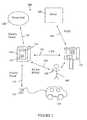
- FIG. 1A first embodiment of the network-controlled charge transfer system 100 for charging electric vehicles is shown in FIG. 1 .
- the system 100comprises a network-controlled charge transfer device 110 , a local power grid 120 , a data control unit 130 , and a server 140 .
- the system 100interfaces with an electric vehicle 150 , with an electrical connector 152 , and an electric vehicle operator 160 , via a mobile communication device 162 .
- the network-controlled charge transfer device 110referred to herein as a SmartletTM, is connected to the local power grid 120 by an electric power line 170 , and to the electric vehicle 150 by the electrical connector 152 .
- the flow of electrical powermay be in either direction for both of these electrical connections.
- the electric vehicle 150can be recharged from the local power grid 120 , or the local power grid 120 can receive power from the electric vehicle 150 .
- the SmartletTM 110has a communication link to the data control unit 130 over a local area network (LAN) 180 .
- the LAN 180may be either a wireless local area network (WLAN) or a power line communication (PLC) network.
- the data control unit 130has a communication link to the server 140 over a wide area network (WAN) 185 .
- the electric vehicle operator 160uses the mobile communication device 162 to establish a communication link to the SmartletTM 110 over a wireless network 190 .
- This wireless networkmay be a WLAN or a wireless personal area network (WPAN).
- the communication link between the electric vehicle operator 160 and the SmartletTM 110allows information to be shared which enables recharging of the electric vehicle 150 .
- the SmartletTM 110comprises an electrical receptacle 112 and indicator lights 114 .
- the electrical receptacle 112 and the electrical connector 152are configured to make an electrical connection allowing safe flow of electrical power between the SmartletTM 110 and the electrical vehicle 150 .
- suitable receptaclesare those conforming to the NEMA (National Electrical Manufacturers Association) standards 5-15, 5-20 and 14-50. Although, other receptacles will be used for systems outside the United States which operate at voltages other than 110V (for example 220V) and which are required to meet different standards.
- the electrical receptacle 112has a cover. The cover is lockable and is released by the SmartletTM 110 upon receipt of a request for charging of an electrical vehicle 150 by the electric vehicle operator 160 . This request may be made by the mobile communication device 162 , as described above.
- the indicator lights 114are used to show the operational status of the SmartletTM 110 —for example, the status may be: charging in progress, charging complete, vehicle-to-grid (V2G) in progress and error warning.
- the indicator lights 114may be LEDs (light emitting diodes), may be capable of showing a number of different colors and may be capable of continuous or flashing modes of operation. Alternatively, the indicator lights 114 may be replaced by an alphanumeric display.
- the local power grid 120is the electrical supply grid owned and operated by local utility companies. Although, the local power grid 120 does extend to parts of the electrical supply network that are not owned by the utility company, such as electrical cables on private premises.
- the data control unit 130acts as a bridge between the LAN and the WAN, and enables communication between the SmartletTM 110 and the server 140 .
- the server 140is generally remote from the SmartletTM 110 .
- the system 100is shown in FIG. 1 with only one SmartletTM 110 ; however, the system will be comprised of many SmartletsTM 110 , all linked to the server 140 through one or more data control units 130 . There will typically be one data control unit 130 for each group of geographically proximate (within the range of the same local area network) SmartletsTM 110 . In addition, in some embodiments the data control unit 130 is included within the SmartletTM 110 and one or more other SmartletsTM communicate with the server 140 through the data control unit 130 within the SmartletTM 110 .
- the SmartletTM 110can operate in a dual charging mode at different voltages (e.g., 120V and 240V).
- a fixably attached charging cordis typically used in a higher voltage mode (e.g., 240V) and an unattached charging cord is used in a lower voltage mode (e.g., 120V).
- the fixably attached charging cordis attached to the SmartletTM 110 and cannot typically be removed by an electric vehicle operator.
- a fixably attached charging cordis used, an electric vehicle operator does not insert a plug into the electrical receptacle 112 , but rather uses the fixably attached charging cord to make an electrical connection between their electric vehicle and the SmartletTM 110 thereby allowing the safe flow of electrical power between the SmartletTM 110 and their electric vehicle.
- the electric vehicle 150is any battery operated electric vehicle, including EVs and plug in hybrids. Electric vehicles 150 that have the necessary V2G electronics are able to provide power to the local power grid 120 .
- the mobile communication device 162used by the electric vehicle operator 160 , can be any type of WLAN or WPAN compatible device. Examples of compatible devices are: one way and two-way RFID devices, an example of the latter being a FasTrac® card; Wi-Fi® devices, such as a personal computer; BlueTooth® devices, such as a mobile phone; and ZigBee® devices.
- the vehicle user 160can monitor charging using the mobile communication device 162 . This can be implemented by allowing access to the vehicle user 160 of the power consumed by the electric vehicle 150 , which is monitored by the SmartletTM 110 and stored on the server 140 . Access can either be directly to the SmartletTM 110 over a LAN or to the server 140 over the Internet.
- FIG. 2A second embodiment of the network controlled charge transfer system 200 for charging electric vehicles 150 is shown in FIG. 2 .
- the system 200comprises a network-controlled charge transfer device (SmartletTM 110 , a local power grid 120 , a payment station 135 , and a server 140 .
- the system 200interfaces with an electric vehicle 150 , with an electrical connector 152 , and an electric vehicle operator 160 , via a mobile communication device 162 .
- the SmartletTM 110is connected to the local power grid 120 by an electric power line 170 , and to the electric vehicle 150 by the electrical connector 152 .
- the flow of electrical powermay be in either direction for both of these electrical connections.
- the SmartletTM 110has a communication link to the payment station 135 over a LAN 180 .
- the LAN 180may be either a WLAN or a PLC network.
- the payment station 135has a communication link to the server 140 over a WAN 185 . (In this embodiment, the payment station 135 is taking the place of the data control unit 130 for acting as a bridge between the LAN and the WAN.)
- the electric vehicle operator 160may use the mobile communication device 162 to establish a communication link to the SmartletTM 110 over a wireless network 190 .
- This wireless networkmay be a WLAN or a WPAN.
- the electric vehicle operator 160may manually interact with the payment station 135 , which then sends appropriate instructions to the SmartletTM 110 regarding charging of the electric vehicle 150 . In preferred embodiments these instructions will include an instruction to unlock a cover over the electrical receptacle 112 , thus allowing the vehicle operator 160 to connect the electric vehicle 150 to the electrical receptacle 112 with the electrical connector 152 .
- the payment station 135can be several tens of meters remote from the SmartletTM 110 .
- the payment station 135is shown comprising a currency reader, a credit card reader, a receipt printer, a display and input buttons. However, the payment station does not have to include all of these components. For example, some payment stations may not include a currency reader and will only allow payment by credit card using the credit card reader.
- the electric vehicle operator 160can use the payment station 135 to pay for and schedule recharging of the electric vehicle 150 , and also for V2G transactions.
- the payment station 135may also be used to pay for parking. Further details of the payment station 135 are provided in FIG. 6 and the related description.
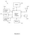
- FIG. 3A schematic of the SmartletTM 110 is provided in FIG. 3 .
- the SmartletTM 110comprises an electrical receptacle 112 , a lockable cover 1125 over the electrical receptacle 112 , a control device 171 , a current measuring device 172 , an electric power line 170 , a controller 111 , a display unit 113 , a vehicle detector 115 , a WLAN transceiver 181 , an alternating current line transceiver 182 , a WPAN transceiver 191 and an RFID transceiver 192 .
- Controller 111is used to lock and unlock the cover 1125 ; the lock mechanism is electromechanical. When unlocked, the cover 1125 may be lifted by the vehicle operator 160 in order to connect the electric vehicle 150 to the electrical receptacle 112 using the electrical connector 152 .
- Control device 171is used to turn the electric supply at the receptacle 112 on and off.
- the control device 171is preferably a solid state device and is controlled by controller 111 .
- the current flowing along the power line 170is measured by current measuring device 172 .
- An example of a suitable measuring device 172is an induction coil.
- the controller 111is programmed to monitor the signal from the current measuring device 172 and to calculate the total power either: consumed (in recharging the electric vehicle); or transferred to the local power grid 120 from the electric vehicle 150 (V2G). It is also envisaged that power may be both consumed and transferred to the grid during the time an electric vehicle is connected to the SmartletTM 110 , in which case the controller 111 will calculate both the power consumed and the power transferred to the local power grid 120 .
- the indicators 114 and display 113are controlled by the controller 111 and are used to provide information to the SmartletTM 110 user.
- the indicators 114are discussed in more detail above, with reference to FIG. 1 , and the display 113 is discussed in more detail below with reference to FIG. 4 .
- Vehicle detector 115is used to detect the presence of a vehicle in the parking space corresponding to the SmartletTM 110 .
- the vehicle detector 115is controlled by the controller 111 .
- the vehicle detector 115is a detector such as a sonar sensor array, a camera, or an induction coil.
- the sonar arrayis an array as used on the rear bumper of automobiles to detect close proximity to an object; this array can be attached to the SmartletTM 110 or will be mounted to a support structure in close proximity to the SmartletTM 110 .
- the camerais a digital camera providing a video signal to the SmartletTM 110 ; the video signal is processed by an object recognition program to detect the presence of a vehicle or other obstruction.
- the induction coilis either embedded in the pavement of the parking space or is protected by a roadworthy casing attached to the surface of the pavement.
- the induction coilis connected to the SmartletTM 110 and detects the presence of large metal objects in close proximity to the coil (such as an engine block, electric motor or rear differential of a vehicle).
- the controller 111is shown with four transceivers—a WLAN transceiver 181 , an alternating current line transceiver 182 , a WPAN transceiver 191 and an RFID transceiver 192 .
- a transceiveris a device that both sends and receives signals, allowing for two-way communication.
- the WLAN transceiver 181allows for the controller to communicate with mobile communication devices which are carried by a vehicle operator 160 (see communication link 190 in FIGS. 1 & 2 ) and with a data control unit 130 or payment station 135 (see communication link 180 in FIGS. 1 & 2 ).
- WLAN transceiver 181could be a Wi-Fi® transceiver.
- the alternating current line transceiverallows the controller to communicate on a PLC network with a control data unit 130 or payment station 135 (see communication link 180 in FIGS. 1 & 2 ).
- the WPAN transceiver 191allows the controller 111 to communicate with mobile communication devices 162 which are carried by the vehicle operator 160 .
- WPAN transceiver 1 91could be a BlueTooth® or ZigBee® transceiver.
- the RFID transceiver 192allows the controller to communicate with a compatible RFID device carried by the vehicle operator 160 .
- An example of an RFID device that could be carried by the vehicle operator 160is a FasTrak® card.
- a FasTrak® deviceis an example of a two-way RFID communication device.
- a one-way RFID communication device from vehicle operator 160 to controller 111can be utilized. Not all embodiments of the SmartletTM 110 have all four types of transceiver; however, all SmartletTM 110 will have at least one wireless transceiver for communication with compatible mobile wireless communication devices 162 available to vehicle operators 160 , and one transceiver for communication with the data control unit 130 . See FIGS. 1 & 2 .
- FIG. 4A more detailed view of the display unit 113 is shown in FIG. 4 .
- An example of parking informationis shown on the display unit 113 —an indicator 1131 shows the paid parking time remaining in minutes 1132 or a parking violation 1133 .
- This parking informationmay be displayed in many other ways than that shown in FIG. 4 .
- the display unit 113may be an LCD (liquid crystal display); although other passive flat panel displays such as OLEDs (organic light emitting displays) and other emissive flat panel displays such as FEDs (field emission displays) may be used. When a passive display unit 113 is used it is preferred that it be backlit, so as to be readily viewed in low ambient light conditions.
- the display unit 113is attached to the SmartletTM 110 so that it is readily observable by the vehicle operator 160 .
- the display 113may be mounted on a pole at a height of approximately 125 cm above the pavement, and the SmartletTM 110 would also be mounted on the pole at a convenient height for the vehicle operator.
- the indicator lights 114may be positioned next to the display 113 , or may be positioned on the SmartletTM 110 itself, as shown in FIGS. 1 & 2 .
- the display 113is controlled by the controller 111 .
- the display 113may also be used to display information regarding the vehicle charging process, such as: time charging, power consumed, estimated time to completion of charging, vehicle-to-grid (V2G) power transferred, general status indications and error warnings.
- V2Gvehicle-to-grid
- the server 140comprises a computer 141 , report generator 142 , and database 143 .
- the server 140is configured to communicate with the following: SmartletTM network 195 ; World Wide Web 197 ; utility companies 144 , for receiving power load management data; credit card companies 145 , for credit authorization and charging; FasTrak® database 146 , for debiting FasTrak® accounts; and banks 146 , for debiting bank accounts.
- the database 143is used to store consumer profiles and other data required for report generation, as described below.
- the report generator 142creates reports such as: utility company reports 1421 , detailing power consumed and V2G power sold to local power grid 120 ; subscriber reports 1422 , detailing power consumed and V2G power sold to the local power grid 120 , account balance, payments and invoices, and subscriber profile data; and tax authority reports 1423 , providing details of taxable transactions.
- the SmartletTM network 195comprises a multiplicity of data control units 130 and/or payment stations 135 , each data control unit 130 and/or payment station 135 being connected by a communication link 180 to a multiplicity of SmartletsTM 110 .
- the communication link 185 between the computer 141 and the SmartletTM network 195is a WAN.
- the server 140is interfaced with the Web 197 to allow subscribers (owners and operators 160 of electric vehicles 150 ) to do the following: (1) set-up user/consumer profiles; and (2) determine availability of SmartletsTM 110 for recharging their electric vehicles 150 .
- a user profilecontains financial account information—details required for payment—and may also include information such as whether the vehicle operator wants to: charge the electric vehicle only during periods of lower power rates; not charge the vehicle during periods of high power grid load; and sell power to the local grid.
- the availability of SmartletsTM 110is stored on the server and the information is collected from the SmartletTM network 195 . There are two ways that the availability of a SmartletTM 11 0 can be determined: (1) using a vehicle detector 115 (see FIG. 3 and related description) to determine whether the parking space corresponding to the SmartletTM 110 is available; and (2) flagging a SmartletTM 110 as being unavailable whenever charging is ongoing, V2G is ongoing or parking has been paid for.
- the payment station 135comprises a controller 1351 , a display 1352 , a set of buttons 1353 , a credit card reader 1354 , a receipt printer 1355 , a currency reader 1356 , a wireless transceiver 1357 and an alternating current line transceiver 1358 .
- the display 1352provides a vehicle operator 160 with information regarding recharging and/or parking their electric vehicle 150 .
- the display 1352shares the same characteristics as the display 113 discussed above with reference to FIG. 4 .
- the display 1352may also be touch sensitive, allowing a vehicle user to input information directly on the display screen 1352 .
- the buttons 1353allow for input of information requested from the display 1352 .
- the credit card reader 1354is used for reading credit cards, debit cards, smart cards, and other cards that are used for identification purposes or for making payment.
- the printer 1355is used for printing receipts, when requested by the consumer.
- the printer 1355may also be used to print receipts for displaying in the electric vehicle 150 to show that recharging and/or parking is properly permitted.
- the currency reader 1356is used for accepting currency—notes and/or coins—for payment.
- the currency reader 1356is able to authenticate and identify the value of currency accepted.
- the payment station 135is networked to SmartletsTM 110 via either a WLAN or a PLC.
- the payment station controller 1351takes the place of data control unit 130 in acting as a bridge between the LAN 180 and the WAN 185 . See FIGS. 1 & 2 .
- a vehicle user 160can use the network-controlled charge transfer systems 100 and 200 for charging their electric vehicle 150 .
- a vehicle user 160 who has a user profile on the server 140is referred to as a subscriber. Some examples of how the systems 100 and 200 can be used are provided below.
- the load management data from the utility companymay limit the ability to recharge the vehicle 150 or the recharge rate for vehicle 150 , according to a Demand Response system.
- the utility companycould send a message to the SmartletTM server 140 requiring a reduction in load.
- the SmartletTM server 140then turns off charging of some vehicles 150 . Which vehicles have charging stopped will depend on the subscriber profiles and the requirements of the Demand Response system.
- the Demand Response system and subscriber profilesmay also allow for V2G.
- V2Gwill result in credits to the subscriber's account for sale of power to the local power grid 120 .
- V2Gwill result in credits to the vehicle user's account for sale of power to the local power grid 120 .
- a parking feemay be imposed in addition to a fee for power consumed in recharging a vehicle.
- a parking feemay be imposed when a vehicle is parked for V2G.
- the SmartletTM 110is coupled with a street light and connects to the power grid through wiring of that street light.
- FIG. 7illustrates an exemplary network-controlled charge transfer system 700 for charging electric vehicles where the SmartletTM 110 is coupled (e.g., mounted) with the street light pole 710 and is connected to the power grid 120 through the wiring of the light pole 710 .
- the system 700interfaces with an electric vehicle 150 , with an electrical connector 152 , and an electric vehicle operator 160 , via the mobile communication device 162 .
- the operator 160may interface with the system 700 without the mobile communication device 162 (e.g., the operator 160 may use input/output device(s) on the SmartletTM 110 (e.g., keypad, touchscreen, etc.)) to interface with the system 700 or use the mobile communication device 162 in combination with other mechanisms.
- the operator 160may use input/output device(s) on the SmartletTM 110 (e.g., keypad, touchscreen, etc.)) to interface with the system 700 or use the mobile communication device 162 in combination with other mechanisms.
- the light pole 710is connected with the local power grid 120 through the wiring box 730 and the electric power line 770 .
- the electric power line 772which provides electricity to illuminate the light 715 , is coupled with the wiring box 730 and is coupled to the power grid 120 via the electric power line 770 .
- the SmartletTM 110is coupled with the light pole 710 and is coupled, via the electronic power line 170 , with the wiring box 730 (which is connected to the power grid 120 via the electric power line 770 ).
- the wiring box 730couples the electric power lines 772 and 170 with the electric power line 770 allowing the light pole 710 and the SmartletTM 110 access to the power grid 120 respectively.
- the SmartletTM 110is coupled with the electric vehicle by the electrical connector 152 over the electric power line 175 .
- the flow of electrical powermay be in either direction for the electric power lines 770 , 170 , and 175 .
- the electric vehicle 150can be recharged from the local power grid 120 and/or the local power grid 120 can receive power from the electric vehicle 150 .
- the SmartletTM 110is linked to the data control unit (DCU) 130 (e.g., over the LAN 180 ) and coupled with the server 140 (e.g., via the DCU 130 ) and operations are performed in a similar fashion to that described in reference to FIG. 1 .
- the SmartletTM 110is liked to the payment station 135 over the LAN 180 and operations are performed in a similar fashion as described in reference to FIG. 2 .
- the SmartletTM 110includes a current measuring device 172 that measures the amount of current flowing across the electric power line 170 .
- the controller 111monitors the signal from the measuring device 172 and calculates the amount of power either consumed from the electric power line 170 (and thus drawn from the electric power line 770 ) (e.g., when recharging electric vehicles and/or the SmartletTM 110 consumes power for internal operation); or transferred to the local power grid 120 from the electric vehicle 150 (e.g., in a V2G case).
- the SmartletTM 110measures and accounts for electricity used and/or generated from individual customers (operators of electric vehicles) and measures and accounts for the total amount of electricity drawn from the power grid 120 and/or added to the power grid 120 .
- the SmartletTM 110may cause individual customers to be charged a monetary amount corresponding to the amount of electricity they have used, and/or cause those customers to be credited and/or paid for the amount of electricity they have produced, while accounting for the total amount of power used from, and/or generated to, the power grid 120 .
- the SmartletTM 110measures the amount of power that it draws from the power grid 120 (via the electric power lines 170 and 770 ) and the amount of power it adds to the power grid 120 (via the electric power lines 170 and 770 ).
- the light pole 710does not include a metering device, the amount of electricity drawn from the wiring of the light pole 710 is accurately measured and accounted, and the amount of electricity added to the power grid 120 is accurately measured and accounted.
- the SmartletTM 110may report the metering information associated with the wiring of the light pole 710 (e.g., the amount of electricity used from, and generated to, the power grid 120 from the wiring of the light pole 710 ) to the utility company operating the power grid 120 for accounting and billing purposes.
- the SmartletTM 110reports the metering information associated with the wiring of the light pole 710 to a server accessible to the utility company operating the power grid 120 .
- the SmartletTM 110reports the metering information over the LAN 180 (e.g., using wired and/or wireless mechanisms) to the DCU 130 which transmits the metering information to the server 140 (which may be accessible by the utility company operating the power grid 120 ).
- the SmartletTM 110reports the metering information associated with the wiring of the light pole 710 directly to the utility company operating the power grid 120 .
- a utility workeraccesses the SmartletTM 110 to read the metering information.
- the SmartletTM 110measures only the current flowing through the electric power line 170 and does not measure the current flowing through the electric power line 772 .
- the SmartletTM 110does not measure the amount of current in the electric power line 772 flowing to the light 715 of the light pole 710 .
- the SmartletTM 110measures the amount of current flowing through the electric power line 170 and separately measures the amount of current flowing through the electric power line 772 .
- the SmartletTM 110may also act as a meter for the light pole 710 . It should also be understood that the SmartletTM 110 may report the metering information of the light pole 710 .
- the SmartletTM 110is directly coupled with the electric power line 772 . That is, in some embodiments of the invention, the SmartletTM 110 shares the electric power line 772 with the light 715 of the light pole 710 .
- the SmartletTM networkmay be used for public and private garage and parking lot charging of electric vehicles.
- the SmartletTM networkmay be used for home charging of electric vehicles, in which case a SmartletTM receptacle in the home is connected via a LAN and a WAN to the SmartletTM server 140 .
- the SmartletTM networkmay also be used for non-vehicle applications, including selling electricity to people in places such as airports and coffee shops.
Landscapes
- Engineering & Computer Science (AREA)
- Power Engineering (AREA)
- Mechanical Engineering (AREA)
- Transportation (AREA)
- Business, Economics & Management (AREA)
- Economics (AREA)
- Physics & Mathematics (AREA)
- General Physics & Mathematics (AREA)
- Theoretical Computer Science (AREA)
- Development Economics (AREA)
- Health & Medical Sciences (AREA)
- Marketing (AREA)
- Strategic Management (AREA)
- General Business, Economics & Management (AREA)
- Accounting & Taxation (AREA)
- Finance (AREA)
- Public Health (AREA)
- Water Supply & Treatment (AREA)
- General Health & Medical Sciences (AREA)
- Human Resources & Organizations (AREA)
- Primary Health Care (AREA)
- Tourism & Hospitality (AREA)
- Charge And Discharge Circuits For Batteries Or The Like (AREA)
- Electric Propulsion And Braking For Vehicles (AREA)
Abstract
Description
- 1. a subscriber uses the Internet to establish a profile, which includes setting-up payment by credit card, debiting a bank account, a FasTrak® account, a Paypal® account, or other financial service;
- 2. the subscriber uses a wireless
mobile communication device 162, such as a mobile phone or a FasTrak® card, to request to theSmartlet™ 110 to charge theelectric vehicle 150; - 3. the subscriber connects the
electric vehicle 150 to theSmartlet™ 110 using the connector152 (seeFIGS. 1 & 2 ); - 4. the
Smartlet™ 110 relays this request over the communication network to theserver 140; - 5. the
server 140 accesses the subscriber profile from thedatabase 143, validates the payment source by contacting the credit card company, FasTrak® database or bank, and via the communication network enables theSmartlet™ 110 to charge thevehicle 150; - 6. based on the subscriber profile and load management data from the utility company the server determines the charging periods and communicates this information to the
Smartlet™ 110; - 7. the
Smartlet™ 110 monitors the charging current, as described above with reference toFIG. 3 ; - 8. when the
vehicle 150 is disconnected from theSmartlet™ 110, charging is disabled and a bill is sent to the payment source. Note that determining when theelectric vehicle 150 is disconnected from theSmartlet™ 110 can be done by: detecting when the current flow goes to zero; or using a sensor on thereceptacle 112 which detects the mechanical removal of theconnector 152. If a sensor is used, the sensor is monitored bycontroller 111. SeeFIG. 3 .
- 1.
vehicle user 160 uses thepayment station 135 to request and pay for charging thevehicle 150; - 2.
vehicle user 160 connects theelectric vehicle 150 to theSmartlet™ 110 usingconnector 152; - 3. the
payment station 135 communicates viaWAN 185 withserver 140 for payment authorization; - 4. the
payment station 135 enables theSmartlet™ 110 for charging; - 5. when the vehicle is disconnected from the
Smartlet™ 110, charging is disabled, thepayment station 135 is notified, thepayment station 135 notifies theserver 140 and a bill is sent to the payment source.
Note that the load management data from the utility company may limit the ability to recharge thevehicle 150 or the recharge rate forvehicle 150, according to a Demand Response system.
- 1.
- 1. a subscriber uses the Internet to establish a profile, which includes setting-up payment by credit card, debiting a bank account, a FasTrak® account, a Paypal® account, or other financial service;
- 2. the subscriber uses a wireless
mobile communication device 162, such as a mobile phone, to request to theSmartlet™ 110 parking for thevehicle 150; - 3. the
Smartlet™ 110 relays this request over the communication network to theserver 140; - 4. the
server 140 accesses the subscriber profile from thedatabase 143, validates the payment source by contacting the credit card company, FasTrak® database or bank, and via the communication network sends a message to theSmartlet™ 110 to allow parking of thevehicle 150; - 5. the
Smartlet™ 110 sets the parking meter shown on display113 (seeFIGS. 3 & 4 ) and sets theindicators 114, if used; - 6. the
server 140 sends a bill to the payment source.
Optionally, if avehicle detector 115 is used to detect the presence of a vehicle, then the amount of time a vehicle is parked without proper payment may be monitored and communicated to thepayment station 135 andserver 140.
- 1.
vehicle user 160 uses thepayment station 135 to request and pay for parking thevehicle 150; - 2. the
payment station 135 communicates viaWAN 185 withserver 140 for payment authorization; - 3. the
payment station 135 communicates to theSmartlet™ 110 to allow parking; - 4. the
server 140 sends a bill to the payment source.
- 1.
Claims (19)
Priority Applications (4)
| Application Number | Priority Date | Filing Date | Title |
|---|---|---|---|
| US13/149,860US8866436B2 (en) | 2008-01-07 | 2011-05-31 | Street light mounted network-controlled charge transfer device for electric vehicles |
| US14/520,058US9431835B2 (en) | 2008-01-07 | 2014-10-21 | Street light mounted network-controlled charge transfer device for electric vehicles |
| US15/250,761US10150381B2 (en) | 2008-01-07 | 2016-08-29 | Street light mounted network-controlled charge transfer device for electric vehicles |
| US16/215,407US10850625B2 (en) | 2008-01-07 | 2018-12-10 | Transferring charge between a local power grid and electric vehicles |
Applications Claiming Priority (5)
| Application Number | Priority Date | Filing Date | Title |
|---|---|---|---|
| US1947408P | 2008-01-07 | 2008-01-07 | |
| US12/013,296US7956570B2 (en) | 2008-01-07 | 2008-01-11 | Network-controlled charging system for electric vehicles |
| US8246208P | 2008-07-21 | 2008-07-21 | |
| US12/505,394US7952319B2 (en) | 2008-01-07 | 2009-07-17 | Street light mounted network-controlled charge transfer device for electric vehicles |
| US13/149,860US8866436B2 (en) | 2008-01-07 | 2011-05-31 | Street light mounted network-controlled charge transfer device for electric vehicles |
Related Parent Applications (1)
| Application Number | Title | Priority Date | Filing Date |
|---|---|---|---|
| US12/505,394ContinuationUS7952319B2 (en) | 2008-01-07 | 2009-07-17 | Street light mounted network-controlled charge transfer device for electric vehicles |
Related Child Applications (1)
| Application Number | Title | Priority Date | Filing Date |
|---|---|---|---|
| US14/520,058ContinuationUS9431835B2 (en) | 2008-01-07 | 2014-10-21 | Street light mounted network-controlled charge transfer device for electric vehicles |
Publications (2)
| Publication Number | Publication Date |
|---|---|
| US20110316478A1 US20110316478A1 (en) | 2011-12-29 |
| US8866436B2true US8866436B2 (en) | 2014-10-21 |
Family
ID=41529738
Family Applications (5)
| Application Number | Title | Priority Date | Filing Date |
|---|---|---|---|
| US12/505,394Active2028-04-22US7952319B2 (en) | 2008-01-07 | 2009-07-17 | Street light mounted network-controlled charge transfer device for electric vehicles |
| US13/149,860Active2028-11-16US8866436B2 (en) | 2008-01-07 | 2011-05-31 | Street light mounted network-controlled charge transfer device for electric vehicles |
| US14/520,058ActiveUS9431835B2 (en) | 2008-01-07 | 2014-10-21 | Street light mounted network-controlled charge transfer device for electric vehicles |
| US15/250,761ActiveUS10150381B2 (en) | 2008-01-07 | 2016-08-29 | Street light mounted network-controlled charge transfer device for electric vehicles |
| US16/215,407ActiveUS10850625B2 (en) | 2008-01-07 | 2018-12-10 | Transferring charge between a local power grid and electric vehicles |
Family Applications Before (1)
| Application Number | Title | Priority Date | Filing Date |
|---|---|---|---|
| US12/505,394Active2028-04-22US7952319B2 (en) | 2008-01-07 | 2009-07-17 | Street light mounted network-controlled charge transfer device for electric vehicles |
Family Applications After (3)
| Application Number | Title | Priority Date | Filing Date |
|---|---|---|---|
| US14/520,058ActiveUS9431835B2 (en) | 2008-01-07 | 2014-10-21 | Street light mounted network-controlled charge transfer device for electric vehicles |
| US15/250,761ActiveUS10150381B2 (en) | 2008-01-07 | 2016-08-29 | Street light mounted network-controlled charge transfer device for electric vehicles |
| US16/215,407ActiveUS10850625B2 (en) | 2008-01-07 | 2018-12-10 | Transferring charge between a local power grid and electric vehicles |
Country Status (1)
| Country | Link |
|---|---|
| US (5) | US7952319B2 (en) |
Cited By (6)
| Publication number | Priority date | Publication date | Assignee | Title |
|---|---|---|---|---|
| US9114719B1 (en) | 2010-06-02 | 2015-08-25 | Bryan Marc Failing | Increasing vehicle security |
| US20160056647A1 (en)* | 2014-08-25 | 2016-02-25 | Samsung Electronics Co., Ltd. | Cradle for Electronic Device |
| US20170050530A1 (en)* | 2008-01-07 | 2017-02-23 | Chargepoint, Inc. | Street Light Mounted Network-Controlled Charge Transfer Device for Electric Vehicles |
| US9889761B2 (en) | 2008-01-07 | 2018-02-13 | Chargepoint, Inc. | Network-controlled charging system for electric vehicles |
| US10220719B2 (en) | 2014-11-17 | 2019-03-05 | Siemens Industry, Inc. | EVSE-based energy automation, management, and protection systems and methods |
| US11135937B2 (en)* | 2018-04-06 | 2021-10-05 | Cisco Technology, Inc. | Vehicle charging leveraging telecommunication infrastructure |
Families Citing this family (99)
| Publication number | Priority date | Publication date | Assignee | Title |
|---|---|---|---|---|
| US20070288265A1 (en)* | 2006-04-28 | 2007-12-13 | Thomas Quinian | Intelligent device and data network |
| JP4341712B2 (en)* | 2007-09-10 | 2009-10-07 | トヨタ自動車株式会社 | Charge control device and charge control method for power storage mechanism |
| US20090177580A1 (en)* | 2008-01-07 | 2009-07-09 | Lowenthal Richard W | Collection of electric vehicle power consumption tax |
| US20100241447A1 (en)* | 2008-04-25 | 2010-09-23 | Polyremedy, Inc. | Customization of wound dressing using rule-based algorithm |
| US8710796B2 (en) | 2009-07-28 | 2014-04-29 | Bosch Automotive Service Solutions Llc | Electric vehicle supply equipment having a socket and a method of charging an electric vehicle |
| US8718717B2 (en)* | 2009-07-30 | 2014-05-06 | Orna Vaknin | Public cellular telephone charging station |
| US20110145141A1 (en)* | 2009-10-02 | 2011-06-16 | James Blain | Method and apparatus for recharging electric vehicles |
| US8604750B2 (en) | 2010-02-23 | 2013-12-10 | Optimization Technologies, Inc. | Electric vehicle charging stations with touch screen user interface |
| US8710798B2 (en)* | 2010-02-23 | 2014-04-29 | Optimization Technologies, Inc. | Electric vehicle charging station parking meter systems |
| ITMI20100361A1 (en)* | 2010-03-05 | 2011-09-06 | Maurizio Carrera | DEVICE FOR LOADING THE BATTERY OF AN EQUIPMENT EQUIPPED WITH AN ELECTRIC MOTOR |
| FR2958091B1 (en)* | 2010-03-23 | 2012-06-01 | Citelum | METHOD FOR CONTROLLING POWER SUPPLY FROM A PUBLIC NETWORK ASSIGNED TO LIGHTING THE PUBLIC ROAD |
| FI20105371A0 (en)* | 2010-04-12 | 2010-04-12 | Teclux Oy | Ulkovalaisujärjestelmä |
| CN101834464A (en)* | 2010-05-11 | 2010-09-15 | 梅勒电气(武汉)有限公司 | Charging pile for electric vehicle |
| USD632645S1 (en) | 2010-06-25 | 2011-02-15 | James Blain | Vehicle recharge station |
| CN102340149A (en)* | 2010-07-20 | 2012-02-01 | 曾伟秋 | Method and device for using street light pole as electric vehicle charging pile |
| WO2012148597A1 (en) | 2011-04-29 | 2012-11-01 | Electric Transportation Engineering Corporation, D/B/A Ecotality North America | Device to facilitate moving an electrical cable of an electric vehicle charging station and method of providing the same |
| WO2012148596A1 (en) | 2011-04-29 | 2012-11-01 | Electric Transportation Engineering Corporation, D/B/A Ecotality North America | System for measuring electricity and method of providing and using the same |
| DE102010038683A1 (en)* | 2010-07-30 | 2012-02-02 | Elektro-Bauelemente Gmbh | Method for providing access to a plug-in element |
| CA2811164C (en) | 2010-09-13 | 2021-01-26 | Addenergie Technologies Inc. | Electric vehicle charging station and method for charging an electric vehicle |
| KR101181186B1 (en) | 2010-10-20 | 2012-09-18 | 현대자동차주식회사 | Telematics of Electric Vehicle for Remote HVAC Control and Its Remote HVAC Control Method |
| DE112011103613T5 (en) | 2010-10-29 | 2013-08-14 | Abb Research Ltd. | Sending mobile energy resources to respond to electrical grid conditions |
| US8712595B2 (en)* | 2011-01-18 | 2014-04-29 | General Electric Company | Dynamic load profiling in a power network |
| MX2013009102A (en)* | 2011-02-07 | 2014-02-27 | Media Cart Holdings Inc | Contact charging system for vehicle-mounted batteries. |
| DE102011010809A1 (en)* | 2011-02-09 | 2012-08-09 | Rwe Ag | Charging station and method for securing a charging process of an electric vehicle |
| ITVI20110030A1 (en)* | 2011-02-18 | 2012-08-19 | Ca Sa S R L | MULTIFUNCTIONAL COLUMN |
| US8937456B2 (en) | 2011-04-21 | 2015-01-20 | International Business Machines Corporation | Real time system and method for optimizing and managing a load in an electrical grid |
| US20120290470A1 (en)* | 2011-05-11 | 2012-11-15 | Samsung Electro-Mechanics Company, Ltd. | Payment systems and methods for providing wireless power transfer |
| WO2012160481A2 (en)* | 2011-05-24 | 2012-11-29 | Koninklijke Philips Electronics N.V. | A charging module, a server, and a charging system comprising the charging module and the server |
| US8624719B2 (en)* | 2011-06-03 | 2014-01-07 | Bosch Automotive Service Solutions Llc | Smart phone control and notification for an electric vehicle charging station |
| CN103597152A (en)* | 2011-06-09 | 2014-02-19 | 三得利控股株式会社 | Safety fence |
| JP5851730B2 (en)* | 2011-06-15 | 2016-02-03 | 三菱重工業株式会社 | Charging system, charging management device, charging management method, and program |
| GB201115322D0 (en) | 2011-09-06 | 2011-10-19 | Electric Car Charging Company Ltd | An improved lamp column |
| FR2979763B1 (en)* | 2011-09-07 | 2015-04-10 | Electricite De France | METHOD AND DEVICE FOR OPTIMIZED RECHARGING OF ELECTRIC BATTERY |
| EP2575230B1 (en) | 2011-09-30 | 2018-11-07 | ABB Research Ltd. | Systems and methods for integrating demand response with service restoration in an electric distribution system |
| IN2014CN03453A (en) | 2011-10-31 | 2015-07-03 | Abb Research Ltd | |
| WO2013073625A1 (en)* | 2011-11-15 | 2013-05-23 | 株式会社 東芝 | Billing system and electric vehicle charging system |
| CN103123732B (en)* | 2011-11-21 | 2016-08-10 | 鸿富锦精密工业(深圳)有限公司 | A kind of public charging management system and charging method |
| JP5967516B2 (en)* | 2011-11-22 | 2016-08-10 | パナソニックIpマネジメント株式会社 | Power management apparatus, power management program, and power distribution system |
| WO2013121472A2 (en)* | 2012-02-13 | 2013-08-22 | Toyota Jidosha Kabushiki Kaisha | Feed cable, power supply system and electric-powered vehicle |
| GB201204818D0 (en)* | 2012-03-19 | 2012-05-02 | Hodgson Richard | Lamp standard |
| JP6243099B2 (en)* | 2012-04-04 | 2017-12-06 | ソニー株式会社 | Power feeding device, power receiving device, state management method, and program |
| US9760875B2 (en)* | 2012-04-05 | 2017-09-12 | Menolinx System Ltd. | Device and method for automatic billing of power consumption through street poles |
| EP2891376B1 (en)* | 2012-08-28 | 2016-11-02 | KOC Universitesi | A method for generating a time table for sensors |
| US9436944B2 (en) | 2012-08-29 | 2016-09-06 | Optimization Technologies, Inc. | Electric vehicle charging station mobile device payment system |
| CN102840859B (en)* | 2012-08-31 | 2015-10-07 | 鸿富锦精密工业(深圳)有限公司 | Charging guider, system and charging air navigation aid |
| EP2909805A4 (en)* | 2012-10-22 | 2016-06-08 | Jean-Louis Fiorucci | APPARATUS AND METHODS FOR PROVIDING URBAN SERVICES |
| EP2920023B1 (en)* | 2012-11-19 | 2019-11-06 | Liros Power Solution AB | Electrical vehicle batterry charger mounted on lamp post |
| DE102012023252B4 (en)* | 2012-11-29 | 2016-11-10 | Selux Ag | Luminaire with electric charging station for electric vehicles |
| US9577435B2 (en) | 2013-03-13 | 2017-02-21 | Abb Research Ltd. | Method and apparatus for managing demand response resources in a power distribution network |
| FR3008237B1 (en)* | 2013-07-08 | 2017-04-14 | Inesocompany Ltd | METHOD AND SYSTEM FOR BATTERY CHARGING |
| US20150100393A1 (en)* | 2013-10-04 | 2015-04-09 | Tseng-Fu Yeh | Toll charging device |
| JP6361132B2 (en)* | 2013-12-24 | 2018-07-25 | トヨタ自動車株式会社 | Contactless power transfer system, charging station, and vehicle |
| CN103762713B (en)* | 2013-12-27 | 2016-06-08 | 广州奥迪通用照明有限公司 | A kind of outdoor central power supply system with charge function |
| US20160350734A1 (en)* | 2014-06-01 | 2016-12-01 | Gideon Samid | Versatile, Real Time, Two-Ways Payment for Power and Utilities |
| TWI536322B (en)* | 2014-06-11 | 2016-06-01 | Qi-Qing Tong | A charging device charging the wireless parking |
| US10045177B2 (en) | 2014-06-13 | 2018-08-07 | Samsung Electronics Co., Ltd. | Method and device for selective communication service in communication system |
| US10431997B2 (en)* | 2014-09-14 | 2019-10-01 | Electric Motor Werks, Inc. | Computerized information system for smart grid integrated electric vehicle charging and associated method |
| US10870358B2 (en) | 2014-09-14 | 2020-12-22 | Enel X North America, Inc. | Systems and methods for enabling automatic management of power loads and power generation based on user-specified set of rules |
| US10850629B2 (en) | 2014-09-14 | 2020-12-01 | Enel X North America, Inc. | Systems and methods for integration of electric vehicle charging stations with photovoltaic, wind, hydro, thermal and other alternative energy generation equipment |
| US9987941B2 (en)* | 2014-09-14 | 2018-06-05 | Electric Motor Werks, Inc. | Systems and methods for local autonomous response to grid conditions by electric vehicle charging stations |
| US9754496B2 (en) | 2014-09-30 | 2017-09-05 | Elwha Llc | System and method for management of airspace for unmanned aircraft |
| US9919797B2 (en) | 2014-12-04 | 2018-03-20 | Elwha Llc | System and method for operation and management of reconfigurable unmanned aircraft |
| US20160272310A1 (en) | 2014-12-04 | 2016-09-22 | Elwha Llc | Reconfigurable unmanned aircraft system |
| CN105739591B (en)* | 2014-12-12 | 2017-07-14 | 国家电网公司 | The integrated power regulation device of light beacon based on direct current supply and system |
| NL2015058B1 (en)* | 2015-06-30 | 2016-08-02 | Lightwell B V | System for charging electric vehicles and method for controlling thereof. |
| US20170015414A1 (en)* | 2015-07-15 | 2017-01-19 | Elwha Llc | System and method for power transfer to an unmanned aircraft |
| US9878787B2 (en) | 2015-07-15 | 2018-01-30 | Elwha Llc | System and method for operating unmanned aircraft |
| CN105140982B (en)* | 2015-07-23 | 2017-10-31 | 超威电源有限公司 | A kind of wireless induction electric car battery charge prompting method and device |
| US9840156B2 (en) | 2015-08-14 | 2017-12-12 | Siemens Industry, Inc. | Automatically selecting charging routine for an electric vehicle by balancing utility and user considerations |
| EP3131052A1 (en)* | 2015-08-14 | 2017-02-15 | Mastercard International Incorporated | Controlling transfer of electrical power |
| US10673258B2 (en) | 2015-08-17 | 2020-06-02 | Nokia Technologies Oy | Methods, apparatuses and computer-readable instructions for activating charging of an electric vehicle |
| CN105634091A (en)* | 2016-02-04 | 2016-06-01 | 任荣源 | Intelligent electric vehicle charging pile |
| CN105634090A (en)* | 2016-02-04 | 2016-06-01 | 任荣源 | All-in-one integrated charging system |
| CN105539191A (en)* | 2016-02-04 | 2016-05-04 | 任红霞 | Photovoltaic charging pile for electric automobile |
| EP3249286B1 (en)* | 2016-05-23 | 2018-11-21 | ICGH Investment and Consulting GmbH | Installation for illuminating an environment |
| IT201600087765A1 (en)* | 2016-08-29 | 2018-03-01 | Convergenze S P A | Column or charging station for electric vehicles. |
| US10630089B2 (en)* | 2016-11-14 | 2020-04-21 | Eaton Intelligent Power Limited | Electric vehicle charging circuit breaker |
| CN106627209A (en)* | 2016-11-23 | 2017-05-10 | 常州尼诺光电科技有限公司 | Cable type electric automobile charging system and working method thereof |
| US20180147944A1 (en)* | 2016-11-26 | 2018-05-31 | Henry Allen Perkins | Superaaacharge |
| JP6870179B2 (en)* | 2017-03-01 | 2021-05-12 | 株式会社日本総合研究所 | Management server, control method and control program in power transfer network system |
| US20200051185A1 (en)* | 2017-03-31 | 2020-02-13 | Environment Partners Pty Ltd | Improvements in energy monitoring |
| US10070265B1 (en) | 2017-04-03 | 2018-09-04 | General Electric Company | System for selective accuracy of an indoor positioning system |
| CN107933360A (en)* | 2017-12-08 | 2018-04-20 | 成都奥尼克斯科技有限公司 | A kind of battery truck charging management system based on network control |
| GB2573750A (en)* | 2018-05-09 | 2019-11-20 | Centrica Plc | System for controlling energy supply and processing energy transactions |
| CN109130912A (en)* | 2018-08-28 | 2019-01-04 | 芜湖炬胜机电设备厂 | A kind of new-energy automobile parking stall charging pile management method |
| CN109130911A (en)* | 2018-08-28 | 2019-01-04 | 芜湖炬胜机电设备厂 | A kind of new-energy automobile parking stall charging pile management system |
| CN109204021A (en)* | 2018-08-28 | 2019-01-15 | 芜湖炬胜机电设备厂 | The intelligent management method of new-energy automobile parking stall charging pile |
| CN110682814B (en)* | 2019-08-16 | 2021-01-05 | 国网浙江省电力有限公司湖州供电公司 | Intelligent shore power device controlled by ubiquitous Internet of things |
| US11173804B2 (en) | 2019-10-01 | 2021-11-16 | Honda Motor Co., Ltd. | V1G or V2G selection |
| IT201900020838A1 (en) | 2019-11-13 | 2021-05-13 | Wireless Network Sites Tech Srl | Lighting Body with Transparent Antennas and Heat Exchangers |
| US11180048B1 (en) | 2020-07-01 | 2021-11-23 | Toyota Motor North America, Inc. | Transport-based exchange of electrical charge and services |
| US11999247B2 (en) | 2020-07-01 | 2024-06-04 | Toyota Motor North America, Inc. | Providing transport to transport energy transfer |
| US11116062B1 (en)* | 2020-11-23 | 2021-09-07 | Ubicquia, Inc. | Streetlight-based power tap |
| US11413977B2 (en)* | 2020-12-11 | 2022-08-16 | Dovene Komi Deh | Charging assembly for electric vehicle |
| NL2030621B1 (en)* | 2022-01-19 | 2023-08-01 | Barton Gould Kenneth | Charging system for electrically powered vehicles |
| US20230256845A1 (en)* | 2022-02-16 | 2023-08-17 | The StressCrete Group | Fully enclosed secure ev charging system |
| US20240075833A1 (en)* | 2022-05-04 | 2024-03-07 | Harrison Metals, Inc. | Utility Pole Mounted Charging Station |
| US20230406124A1 (en) | 2022-06-16 | 2023-12-21 | Eaton Intelligent Power Limited | Electric vehicle charging system and connector having an rfid reader and method for rf validation for charging electric vehicle |
| US20240046797A1 (en)* | 2022-08-08 | 2024-02-08 | Toyota Motor North America, Inc. | Grid-related event prediction |
Citations (47)
| Publication number | Priority date | Publication date | Assignee | Title |
|---|---|---|---|---|
| US4532418A (en) | 1982-08-30 | 1985-07-30 | The Detroit Edison Company | Microprocessor electric vehicle charging and parking meter system structure and method |
| US5297664A (en) | 1992-06-26 | 1994-03-29 | Tseng Ling Yuan | Electric charging/parking meter |
| US5548200A (en) | 1994-07-06 | 1996-08-20 | Norvik Traction Inc. | Universal charging station and method for charging electric vehicle batteries |
| US5563491A (en) | 1992-03-30 | 1996-10-08 | Tseng; Ling-Yuan | Combined parking meter and electric-vehicle battery charger with remote status receiver |
| US5742229A (en) | 1993-05-25 | 1998-04-21 | Intellectual Property Development Associates Of Connecticut, Inc. | Methods and apparatus for dispensing a consumable energy source to a vehicle |
| US5812643A (en) | 1997-02-06 | 1998-09-22 | Powertel, Inc. | Power and telecommunications access vending machine |
| US5815824A (en) | 1995-03-06 | 1998-09-29 | Mitsubishi Jidosha Kogyo Kabushiki Kaisha | Navigation system for electric automobile |
| US6081205A (en) | 1992-05-19 | 2000-06-27 | Williams; Douglas J. | Electronic parking meter and electric automobile recharging station |
| WO2001004984A1 (en) | 1999-07-08 | 2001-01-18 | Ztek Corporation | An off-board station and an electricity exchanging system suitable for use with a mobile vehicle power system |
| US6314169B1 (en) | 1997-02-06 | 2001-11-06 | Poweroasis, Inc. | Power and telecommunications access vending machine |
| US20020099574A1 (en) | 2001-01-22 | 2002-07-25 | Cahill John J. | Method of electronically reserving a space for parking a vehicle |
| US20020116282A1 (en) | 2000-05-23 | 2002-08-22 | Martin Jeffrey W. | Methods and systems for correlating consumption information with distribution entities |
| US6487508B1 (en) | 1998-07-29 | 2002-11-26 | Hitachi, Ltd. | Energy supply system and operation method thereof |
| US20030120442A1 (en) | 2001-12-21 | 2003-06-26 | Pellegrino Nicholas J. | Charging station for hybrid powered vehicles |
| JP2003259552A (en) | 2002-02-27 | 2003-09-12 | Sharp Corp | Distributed power management system, distributed power system used therefor, and management server |
| US20040030619A1 (en) | 2002-01-16 | 2004-02-12 | Stokes Patricia L. | System and method for calculating transaction-based taxes |
| US6791473B2 (en) | 2001-11-30 | 2004-09-14 | Telecommunications Research Laboratory | Smart parking meter system |
| US6812857B1 (en) | 1999-11-12 | 2004-11-02 | Shaffiq Kassab | Parking meter control dispatch and information system and method |
| CN1561498A (en) | 2001-10-11 | 2005-01-05 | 卓信科技有限公司 | Apparatus, method and system for payment using mobile device |
| US20050035741A1 (en) | 2003-08-11 | 2005-02-17 | David Elder | Multiple battery management system, auxiliary battery attachment system, and network controlled multiple battery system |
| CN1614647A (en) | 2004-12-03 | 2005-05-11 | 郭建国 | Parking information terminal, onboard remote controller, parking meter and network system |
| US6930410B2 (en) | 2001-04-27 | 2005-08-16 | Sharp Kabushiki Kaisha | Mobile receptacle, power feeding gate device, server device and power usage management system for efficiently delivering electric power |
| US20050273218A1 (en) | 1995-06-07 | 2005-12-08 | Automotive Technologies International, Inc. | System for obtaining vehicular information |
| JP2006074867A (en) | 2004-08-31 | 2006-03-16 | Fuji Heavy Ind Ltd | Vehicle battery charging system |
| US20060224484A1 (en) | 2005-04-04 | 2006-10-05 | Eli Nhaissi | System and method of economic taxation |
| US20060250278A1 (en) | 2005-05-09 | 2006-11-09 | The Boeing Company | System and method for assessing parking space occupancy and for reserving same |
| JP2007066278A (en) | 2005-08-30 | 2007-03-15 | Yoshito Matsuo | Power supply system to storage battery-driven electric vehicle or like |
| US20070179692A1 (en) | 2006-02-02 | 2007-08-02 | Signature Control Systems, Inc. | Method, system and device for monitoring vehicle usage |
| US7254468B2 (en) | 2001-12-21 | 2007-08-07 | Oshkosh Truck Corporation | Multi-network control system for a vehicle |
| US20070282495A1 (en) | 2006-05-11 | 2007-12-06 | University Of Delaware | System and method for assessing vehicle to grid (v2g) integration |
| WO2007141543A2 (en) | 2006-06-08 | 2007-12-13 | Elektromotive Ltd. | Charging station |
| US20080040296A1 (en) | 2006-08-10 | 2008-02-14 | V2 Green Inc. | Electric Resource Power Meter in a Power Aggregation System for Distributed Electric Resources |
| US20080040263A1 (en) | 2006-08-10 | 2008-02-14 | V2 Green, Inc. | Business Methods in a Power Aggregation System for Distributed Electric Resources |
| US20080052145A1 (en) | 2006-08-10 | 2008-02-28 | V2 Green, Inc. | Power Aggregation System for Distributed Electric Resources |
| US20080281663A1 (en) | 2007-05-09 | 2008-11-13 | Gridpoint, Inc. | Method and system for scheduling the discharge of distributed power storage devices and for levelizing dispatch participation |
| US20090040029A1 (en) | 2006-08-10 | 2009-02-12 | V2Green, Inc. | Transceiver and charging component for a power aggregation system |
| US20090079388A1 (en) | 2007-09-20 | 2009-03-26 | Mahidhar Reddy | Automated recharging system |
| US20090082957A1 (en) | 2007-09-20 | 2009-03-26 | Shai Agassi | Electric Vehicle Network |
| US7538690B1 (en) | 2006-01-27 | 2009-05-26 | Navteq North America, Llc | Method of collecting parking availability information for a geographic database for use with a navigation system |
| US20090150073A1 (en) | 2007-12-06 | 2009-06-11 | Orvill Caraballo | Graphic interface method and apparatus for navigation system for providing parking information |
| US20090229900A1 (en) | 2008-03-13 | 2009-09-17 | International Business Machines Corporation | Plugin hybrid electric vehicle with v2g optimization system |
| US20100010698A1 (en) | 2006-08-02 | 2010-01-14 | Kabushiki Kaisha Tokai Rika Denki Seisakusho | Charging System |
| US7693609B2 (en) | 2007-09-05 | 2010-04-06 | Consolidated Edison Company Of New York, Inc. | Hybrid vehicle recharging system and method of operation |
| US7747739B2 (en) | 2006-08-10 | 2010-06-29 | Gridpoint, Inc. | Connection locator in a power aggregation system for distributed electric resources |
| US20100228405A1 (en) | 2007-06-13 | 2010-09-09 | Intrago Corporation | Shared vehicle management system |
| US7952319B2 (en)* | 2008-01-07 | 2011-05-31 | Coulomb Technologies, Inc. | Street light mounted network-controlled charge transfer device for electric vehicles |
| US7956570B2 (en) | 2008-01-07 | 2011-06-07 | Coulomb Technologies, Inc. | Network-controlled charging system for electric vehicles |
Family Cites Families (36)
| Publication number | Priority date | Publication date | Assignee | Title |
|---|---|---|---|---|
| US586193A (en) | 1897-07-13 | transmitting electrical signals | ||
| JPH05276681A (en) | 1992-03-27 | 1993-10-22 | Nissan Motor Co Ltd | Charging device |
| SE9202823L (en) | 1992-09-30 | 1994-03-31 | Volvo Ab | Device and method for charging electric vehicles |
| US6727809B1 (en) | 1993-05-25 | 2004-04-27 | Intellectual Property Development Associates Of Connecticut, Inc. | Methods for providing information, messages and advertisements to a user of a fuel pump that is coupled to remote computers through a data communications network |
| US5927938A (en) | 1994-01-06 | 1999-07-27 | Unlimited Range Electric Car Systems Company | Battery charging and transfer system for electrically powered vehicles |
| JPH10271694A (en) | 1997-03-24 | 1998-10-09 | Nissan Motor Co Ltd | Charging/discharging system of secondary battery |
| US5926004A (en) | 1997-10-10 | 1999-07-20 | Schott Power Systems Incorporated | Method and apparatus for charging one or more electric vehicles |
| US6927700B1 (en) | 2000-01-04 | 2005-08-09 | Joseph P. Quinn | Method and apparatus for detection and remote notification of vehicle parking space availability data |
| US7256516B2 (en) | 2000-06-14 | 2007-08-14 | Aerovironment Inc. | Battery charging system and method |
| DE20013399U1 (en) | 2000-08-03 | 2000-11-02 | Chai, Wellmon, Taichung | Charging station for electrically powered vehicles |
| JP3758140B2 (en) | 2001-07-09 | 2006-03-22 | 日産自動車株式会社 | Information presentation device |
| JP4071197B2 (en) | 2002-01-24 | 2008-04-02 | アロイス・ヴォベン | Car |
| JP2003259696A (en) | 2002-02-28 | 2003-09-12 | Jfe Engineering Kk | Power generation control method and program thereof |
| JP3755490B2 (en) | 2002-07-11 | 2006-03-15 | 株式会社デンソー | Electric vehicle charging system, computer program, and electric vehicle charging method |
| JP2006094655A (en) | 2004-09-24 | 2006-04-06 | Sharp Corp | Power supply system and mobile phone |
| CN1261319C (en) | 2004-11-11 | 2006-06-28 | 北京电巴科技有限公司 | An electric bus system |
| JP2006204081A (en) | 2004-12-24 | 2006-08-03 | Hitachi Ltd | Supply and demand adjustment method, system and service by distributed power supply |
| CN101171718B (en) | 2005-03-11 | 2012-08-22 | 泰克蒂姆有限公司 | Bidirectional Battery Charge Controller |
| US8042631B2 (en) | 2005-04-04 | 2011-10-25 | Delphi Technologies, Inc. | Electric vehicle having multiple-use APU system |
| US7834778B2 (en) | 2005-08-19 | 2010-11-16 | Gm Global Technology Operations, Inc. | Parking space locator |
| JP5078119B2 (en) | 2005-12-06 | 2012-11-21 | トヨタ自動車株式会社 | Charger |
| US8026698B2 (en) | 2006-02-09 | 2011-09-27 | Scheucher Karl F | Scalable intelligent power supply system and method |
| GB0612794D0 (en) | 2006-06-28 | 2006-08-09 | Filtronic Compound Semiconduct | A linear antenna switch arm and a field effect transistor |
| JP2008054439A (en) | 2006-08-25 | 2008-03-06 | Toyota Motor Corp | Power system |
| US20090192927A1 (en) | 2006-09-13 | 2009-07-30 | Berg Michel J | Enhanced power outlet system incorporating a smart receptacle |
| US7566003B2 (en) | 2006-12-07 | 2009-07-28 | Specialty Acquirer Llc | Learning fare collection system for mass transit |
| US7885893B2 (en) | 2007-03-16 | 2011-02-08 | Daniel Alexander | Method and system for the authorization of and payment for electric charging of vehicles |
| US20080312782A1 (en) | 2007-06-15 | 2008-12-18 | Gene Berdichevsky | Electric vehicle communication interface |
| US20090021213A1 (en) | 2007-07-20 | 2009-01-22 | Oriz Wickline Johnson | Method for pay-per-use, self-service charging of electric automobiles |
| CN101828318A (en) | 2007-07-26 | 2010-09-08 | 绿箱子技术股份有限公司 | Be used between electrical network and vehicle, transmitting the system and method for electrical power |
| US20090030712A1 (en) | 2007-07-26 | 2009-01-29 | Bradley D. Bogolea | System and method for transferring electrical power between grid and vehicle |
| US8054048B2 (en) | 2007-10-04 | 2011-11-08 | GM Global Technology Operations LLC | Power grid load management for plug-in vehicles |
| WO2010051477A2 (en) | 2008-10-31 | 2010-05-06 | Levinton Manufacturing Company, Ltd. | System and method for charging a vehicle |
| WO2011156776A2 (en) | 2010-06-10 | 2011-12-15 | The Regents Of The University Of California | Smart electric vehicle (ev) charging and grid integration apparatus and methods |
| US20120229085A1 (en)* | 2011-03-07 | 2012-09-13 | Lau David M K | System for charging electric vehicle batteries from street lights and parking meters |
| US20120323643A1 (en) | 2011-03-24 | 2012-12-20 | Premier Parking LLC | Parking management systems and methods |
- 2009
- 2009-07-17USUS12/505,394patent/US7952319B2/enactiveActive
- 2011
- 2011-05-31USUS13/149,860patent/US8866436B2/enactiveActive
- 2014
- 2014-10-21USUS14/520,058patent/US9431835B2/enactiveActive
- 2016
- 2016-08-29USUS15/250,761patent/US10150381B2/enactiveActive
- 2018
- 2018-12-10USUS16/215,407patent/US10850625B2/enactiveActive
Patent Citations (54)
| Publication number | Priority date | Publication date | Assignee | Title |
|---|---|---|---|---|
| US4532418A (en) | 1982-08-30 | 1985-07-30 | The Detroit Edison Company | Microprocessor electric vehicle charging and parking meter system structure and method |
| US5563491A (en) | 1992-03-30 | 1996-10-08 | Tseng; Ling-Yuan | Combined parking meter and electric-vehicle battery charger with remote status receiver |
| US6081205A (en) | 1992-05-19 | 2000-06-27 | Williams; Douglas J. | Electronic parking meter and electric automobile recharging station |
| US5297664A (en) | 1992-06-26 | 1994-03-29 | Tseng Ling Yuan | Electric charging/parking meter |
| US5742229A (en) | 1993-05-25 | 1998-04-21 | Intellectual Property Development Associates Of Connecticut, Inc. | Methods and apparatus for dispensing a consumable energy source to a vehicle |
| US5548200A (en) | 1994-07-06 | 1996-08-20 | Norvik Traction Inc. | Universal charging station and method for charging electric vehicle batteries |
| US5815824A (en) | 1995-03-06 | 1998-09-29 | Mitsubishi Jidosha Kogyo Kabushiki Kaisha | Navigation system for electric automobile |
| US20050273218A1 (en) | 1995-06-07 | 2005-12-08 | Automotive Technologies International, Inc. | System for obtaining vehicular information |
| US6380637B1 (en) | 1996-09-19 | 2002-04-30 | Ztek Corporation | Off-board station and an electricity exchanging system suitable for use with a mobile vehicle power system |
| US6721400B2 (en) | 1997-02-06 | 2004-04-13 | Poweroasis, Inc. | Power and telecommunications access vending machine |
| US6314169B1 (en) | 1997-02-06 | 2001-11-06 | Poweroasis, Inc. | Power and telecommunications access vending machine |
| US5812643A (en) | 1997-02-06 | 1998-09-22 | Powertel, Inc. | Power and telecommunications access vending machine |
| US6466658B2 (en) | 1997-02-06 | 2002-10-15 | Poweroasis, Inc. | Power and telecommunications access vending machine |
| US6487508B1 (en) | 1998-07-29 | 2002-11-26 | Hitachi, Ltd. | Energy supply system and operation method thereof |
| WO2001004984A1 (en) | 1999-07-08 | 2001-01-18 | Ztek Corporation | An off-board station and an electricity exchanging system suitable for use with a mobile vehicle power system |
| US6812857B1 (en) | 1999-11-12 | 2004-11-02 | Shaffiq Kassab | Parking meter control dispatch and information system and method |
| US20020116282A1 (en) | 2000-05-23 | 2002-08-22 | Martin Jeffrey W. | Methods and systems for correlating consumption information with distribution entities |
| US20020099574A1 (en) | 2001-01-22 | 2002-07-25 | Cahill John J. | Method of electronically reserving a space for parking a vehicle |
| US6930410B2 (en) | 2001-04-27 | 2005-08-16 | Sharp Kabushiki Kaisha | Mobile receptacle, power feeding gate device, server device and power usage management system for efficiently delivering electric power |
| CN1561498A (en) | 2001-10-11 | 2005-01-05 | 卓信科技有限公司 | Apparatus, method and system for payment using mobile device |
| US6791473B2 (en) | 2001-11-30 | 2004-09-14 | Telecommunications Research Laboratory | Smart parking meter system |
| US7254468B2 (en) | 2001-12-21 | 2007-08-07 | Oshkosh Truck Corporation | Multi-network control system for a vehicle |
| US6614204B2 (en) | 2001-12-21 | 2003-09-02 | Nicholas J. Pellegrino | Charging station for hybrid powered vehicles |
| US20030120442A1 (en) | 2001-12-21 | 2003-06-26 | Pellegrino Nicholas J. | Charging station for hybrid powered vehicles |
| US20040030619A1 (en) | 2002-01-16 | 2004-02-12 | Stokes Patricia L. | System and method for calculating transaction-based taxes |
| JP2003259552A (en) | 2002-02-27 | 2003-09-12 | Sharp Corp | Distributed power management system, distributed power system used therefor, and management server |
| US20050035741A1 (en) | 2003-08-11 | 2005-02-17 | David Elder | Multiple battery management system, auxiliary battery attachment system, and network controlled multiple battery system |
| JP2006074867A (en) | 2004-08-31 | 2006-03-16 | Fuji Heavy Ind Ltd | Vehicle battery charging system |
| CN1614647A (en) | 2004-12-03 | 2005-05-11 | 郭建国 | Parking information terminal, onboard remote controller, parking meter and network system |
| US20060224484A1 (en) | 2005-04-04 | 2006-10-05 | Eli Nhaissi | System and method of economic taxation |
| US20060250278A1 (en) | 2005-05-09 | 2006-11-09 | The Boeing Company | System and method for assessing parking space occupancy and for reserving same |
| JP2007066278A (en) | 2005-08-30 | 2007-03-15 | Yoshito Matsuo | Power supply system to storage battery-driven electric vehicle or like |
| US7538690B1 (en) | 2006-01-27 | 2009-05-26 | Navteq North America, Llc | Method of collecting parking availability information for a geographic database for use with a navigation system |
| US20070179692A1 (en) | 2006-02-02 | 2007-08-02 | Signature Control Systems, Inc. | Method, system and device for monitoring vehicle usage |
| US7660652B2 (en) | 2006-02-02 | 2010-02-09 | Signature Control Systems, Inc. | Method, system and device for monitoring vehicle usage |
| US20070282495A1 (en) | 2006-05-11 | 2007-12-06 | University Of Delaware | System and method for assessing vehicle to grid (v2g) integration |
| WO2007141543A2 (en) | 2006-06-08 | 2007-12-13 | Elektromotive Ltd. | Charging station |
| US20100013434A1 (en) | 2006-06-08 | 2010-01-21 | Elektromotive Ltd. | Charging station |
| US20100010698A1 (en) | 2006-08-02 | 2010-01-14 | Kabushiki Kaisha Tokai Rika Denki Seisakusho | Charging System |
| US20080040296A1 (en) | 2006-08-10 | 2008-02-14 | V2 Green Inc. | Electric Resource Power Meter in a Power Aggregation System for Distributed Electric Resources |
| US7747739B2 (en) | 2006-08-10 | 2010-06-29 | Gridpoint, Inc. | Connection locator in a power aggregation system for distributed electric resources |
| US20080040263A1 (en) | 2006-08-10 | 2008-02-14 | V2 Green, Inc. | Business Methods in a Power Aggregation System for Distributed Electric Resources |
| US20090040029A1 (en) | 2006-08-10 | 2009-02-12 | V2Green, Inc. | Transceiver and charging component for a power aggregation system |
| US20080052145A1 (en) | 2006-08-10 | 2008-02-28 | V2 Green, Inc. | Power Aggregation System for Distributed Electric Resources |
| US20080281663A1 (en) | 2007-05-09 | 2008-11-13 | Gridpoint, Inc. | Method and system for scheduling the discharge of distributed power storage devices and for levelizing dispatch participation |
| US20100228405A1 (en) | 2007-06-13 | 2010-09-09 | Intrago Corporation | Shared vehicle management system |
| US7693609B2 (en) | 2007-09-05 | 2010-04-06 | Consolidated Edison Company Of New York, Inc. | Hybrid vehicle recharging system and method of operation |
| US20090082957A1 (en) | 2007-09-20 | 2009-03-26 | Shai Agassi | Electric Vehicle Network |
| US20090079388A1 (en) | 2007-09-20 | 2009-03-26 | Mahidhar Reddy | Automated recharging system |
| US20090150073A1 (en) | 2007-12-06 | 2009-06-11 | Orvill Caraballo | Graphic interface method and apparatus for navigation system for providing parking information |
| US7952319B2 (en)* | 2008-01-07 | 2011-05-31 | Coulomb Technologies, Inc. | Street light mounted network-controlled charge transfer device for electric vehicles |
| US7956570B2 (en) | 2008-01-07 | 2011-06-07 | Coulomb Technologies, Inc. | Network-controlled charging system for electric vehicles |
| US8138715B2 (en) | 2008-01-07 | 2012-03-20 | Coulomb Technologies, Inc. | Network-controlled charging system for electric vehicles through use of a remote server |
| US20090229900A1 (en) | 2008-03-13 | 2009-09-17 | International Business Machines Corporation | Plugin hybrid electric vehicle with v2g optimization system |
Non-Patent Citations (18)
| Title |
|---|
| "Vehicle-to-Grid (V2G) Technology," downloaded Jan. 10, 2008 from http://www.acpropulsion.com/technology/v2g.htm. |
| Final Office Action for U.S. Appl. No. 13/418,296, mailed Dec. 17, 2013, 15 pages. |
| Final Office Action for U.S. Appl.No. 12/335,274, mailed Jan. 31, 2013, 22 pages. |
| First Examination Report for Australian Patent Application No. 2009204279, dated Dec. 3, 2012, 4 pages. |
| First Examination Report for New Zealand Patent Application 613104, dated Jul. 17, 2013, 2 pages. |
| First Examination Report for New Zealand Patent Application No. 586671, mailed Jan. 12, 2012, 2 pages. |
| First Office Action for Chinese Patent Application No. 2009/80104785.4, dated Sep. 15, 2011, 11 pages. |
| First Office Action for JP 2010-542318, dated Jun. 19, 2013, 4 pages. |
| Lin, C. et al., The Installation on Public Area of Recharging Terminals for Electric Vehicles, Whitepaper, undated, pp. 126-135. |
| Lin, et al., "The Installation on Public Area of Recharging Terminals for Electric Vehicles," International Electric Vehicle Symposium, Anaheim, Dec. 5-7, 1994, San Francisco, Whitepaper, pp. 126-135. |
| Non-Final Office Action for U.S Appl. No. 13/418,296, mailed Apr. 29, 2014, 12 pages. |
| Non-Final Office Action for U.S. Appl. No. 13/418,296, mailed Jun. 27, 2013, 22 pages. |
| Notice of Allowance for U.S. Appl. No. 13/418,300, mailed Nov. 28, 2012, 10 pages. |
| Oregon Department of Transportation Final Report on Oregon's Mileage Fee Concept and Road User Fee Pilot Program, Nov. 2007; Oregon Department of Transportation, available at http://www.oregon.gov/ODOT/HWY/OIPP/ruftf.shtml, 101 pages. |
| PCT International Search Report and Written Opinion issued Feb. 5, 2009 for PCT/US09/30276, 10 pages. |
| Rochereau, et al., "EDF and the Electric Vehicle: Comprehensive and standardized charging facilities," Whitepaper, Oct. 13, 1996, pp. 737-741. |
| Rouchereau, H. et al., "EDF and the Electric Vehicle: Comprehensive and Standardized Charging Facilities", Whitepaper, undated, pp. 737-741. |
| Second Office Action for Chinese Patent Application No. 2009/80104785.4, dated Aug. 17, 2012, 14 pages. |
Cited By (14)
| Publication number | Priority date | Publication date | Assignee | Title |
|---|---|---|---|---|
| US10150381B2 (en)* | 2008-01-07 | 2018-12-11 | Chargepoint, Inc. | Street light mounted network-controlled charge transfer device for electric vehicles |
| US10873210B2 (en) | 2008-01-07 | 2020-12-22 | Chargepoint, Inc. | Network-controlled charging system for electric vehicles |
| US10879733B2 (en) | 2008-01-07 | 2020-12-29 | Chargepoint, Inc. | Network-controlled charging system for electric vehicles |
| US20170050530A1 (en)* | 2008-01-07 | 2017-02-23 | Chargepoint, Inc. | Street Light Mounted Network-Controlled Charge Transfer Device for Electric Vehicles |
| US9889761B2 (en) | 2008-01-07 | 2018-02-13 | Chargepoint, Inc. | Network-controlled charging system for electric vehicles |
| US10850625B2 (en) | 2008-01-07 | 2020-12-01 | Chargepoint, Inc. | Transferring charge between a local power grid and electric vehicles |
| US10124691B1 (en) | 2010-06-02 | 2018-11-13 | Bryan Marc Failing | Energy transfer with vehicles |
| US9114719B1 (en) | 2010-06-02 | 2015-08-25 | Bryan Marc Failing | Increasing vehicle security |
| US9393878B1 (en) | 2010-06-02 | 2016-07-19 | Bryan Marc Failing | Energy transfer with vehicles |
| US11186192B1 (en) | 2010-06-02 | 2021-11-30 | Bryan Marc Failing | Improving energy transfer with vehicles |
| US10298036B2 (en)* | 2014-08-25 | 2019-05-21 | Samsung Electronics Co., Ltd. | Cradle for electronic device |
| US20160056647A1 (en)* | 2014-08-25 | 2016-02-25 | Samsung Electronics Co., Ltd. | Cradle for Electronic Device |
| US10220719B2 (en) | 2014-11-17 | 2019-03-05 | Siemens Industry, Inc. | EVSE-based energy automation, management, and protection systems and methods |
| US11135937B2 (en)* | 2018-04-06 | 2021-10-05 | Cisco Technology, Inc. | Vehicle charging leveraging telecommunication infrastructure |
Also Published As
| Publication number | Publication date |
|---|---|
| US10850625B2 (en) | 2020-12-01 |
| US20110316478A1 (en) | 2011-12-29 |
| US20100013436A1 (en) | 2010-01-21 |
| US9431835B2 (en) | 2016-08-30 |
| US7952319B2 (en) | 2011-05-31 |
| US20190381904A1 (en) | 2019-12-19 |
| US20150162764A1 (en) | 2015-06-11 |
| US10150381B2 (en) | 2018-12-11 |
| US20170050530A1 (en) | 2017-02-23 |
Similar Documents
| Publication | Publication Date | Title |
|---|---|---|
| US10850625B2 (en) | Transferring charge between a local power grid and electric vehicles | |
| US10873210B2 (en) | Network-controlled charging system for electric vehicles | |
| JP6692841B2 (en) | Network controlled charging system for electric vehicles | |
| US20110227531A1 (en) | Systems and methods for recharging an electric vehicle | |
| CN102742113B (en) | electric vehicle charging and charging | |
| TWI633023B (en) | Module, electric car and intermediate server for location based power mediation and user authentication socket or connector used for the same | |
| AU2014218477B2 (en) | Network-controlled charging system for electric vehicles | |
| JP2007066278A (en) | Power supply system to storage battery-driven electric vehicle or like |
Legal Events
| Date | Code | Title | Description |
|---|---|---|---|
| AS | Assignment | Owner name:CHARGEPOINT, INC., CALIFORNIA Free format text:CHANGE OF NAME;ASSIGNOR:COULOMB TECHNOLOGIES, INC.;REEL/FRAME:029339/0711 Effective date:20121101 | |
| STCF | Information on status: patent grant | Free format text:PATENTED CASE | |
| AS | Assignment | Owner name:COULOMB TECHNOLOGIES, INC., CALIFORNIA Free format text:ASSIGNMENT OF ASSIGNORS INTEREST;ASSIGNORS:LOWENTHAL, RICHARD;BAXTER, DAVID;BHADE, HARJINDER;AND OTHERS;REEL/FRAME:034570/0756 Effective date:20091005 | |
| AS | Assignment | Owner name:SILICON VALLEY BANK, CALIFORNIA Free format text:SECURITY INTEREST;ASSIGNOR:CHARGEPOINT, INC.;REEL/FRAME:034714/0076 Effective date:20141223 | |
| AS | Assignment | Owner name:ARES CAPITAL CORPORATION, ILLINOIS Free format text:SECURITY INTEREST;ASSIGNOR:CHARGEPOINT, INC.;REEL/FRAME:034757/0811 Effective date:20141224 | |
| AS | Assignment | Owner name:ARES CAPITAL CORPORATION, NEW YORK Free format text:CORRECTIVE ASSIGNMENT TO CORRECT THE ADDRESS OF ASSIGNEE PREVIOUSLY RECORDED ON REEL 034757 FRAME 811. ASSIGNOR(S) HEREBY CONFIRMS THE ASSIGNMENT;ASSIGNOR:CHARGEPOINT, INC.;REEL/FRAME:037105/0583 Effective date:20141224 | |
| AS | Assignment | Owner name:BEARCUB ACQUISITIONS LLC, CALIFORNIA Free format text:ASSIGNMENT OF IP SECURITY AGREEMENT;ASSIGNOR:ARES CAPITAL CORPORATION;REEL/FRAME:044442/0781 Effective date:20171107 | |
| MAFP | Maintenance fee payment | Free format text:PAYMENT OF MAINTENANCE FEE, 4TH YEAR, LARGE ENTITY (ORIGINAL EVENT CODE: M1551) Year of fee payment:4 | |
| AS | Assignment | Owner name:CHARGEPOINT INC., CALIFORNIA Free format text:TERMINATION AND RELEASE OF SECURITY AGREEMENT AT REEL 044442/FRAME 0781;ASSIGNOR:BEARCUB ACQUISITIONS LLC;REEL/FRAME:046531/0749 Effective date:20170711 Owner name:MIDCAP FINANCIAL TRUST, AS AGENT, MARYLAND Free format text:SECURITY AGREEMENT;ASSIGNORS:CHARGEPOINT INC.;CPI INTEGRATION HOLDINGS, INC.;REEL/FRAME:046531/0719 Effective date:20180711 | |
| AS | Assignment | Owner name:MIDCAP FINANCIAL TRUST, AS AGENT, MARYLAND Free format text:CORRECTIVE ASSIGNMENT TO CORRECT THE CORRECTIVE ASSIGNMENT TO CORRECT THE APPLICATION NUMBER LISTED ON PAGE 2, LINE 21, 15894778 PREVIOUSLY RECORDED AT REEL: 46531 FRAME: 719. ASSIGNOR(S) HEREBY CONFIRMS THE SECURITY AGREEMENT;ASSIGNORS:CHARGEPOINT INC.;CPI INTEGRATION HOLDINGS, INC.;REEL/FRAME:054630/0890 Effective date:20180711 | |
| AS | Assignment | Owner name:CHARGEPOINT, INC., CALIFORNIA Free format text:RELEASE;ASSIGNOR:SILICON VALLEY BANK;REEL/FRAME:054064/0295 Effective date:20200924 | |
| AS | Assignment | Owner name:CHARGEPOINT INC., CALIFORNIA Free format text:RELEASE BY SECURED PARTY;ASSIGNOR:MIDCAP FINANCIAL TRUST, AS AGENT;REEL/FRAME:055632/0704 Effective date:20210315 Owner name:CPI INTEGRATION HOLDINGS, INC., CALIFORNIA Free format text:RELEASE BY SECURED PARTY;ASSIGNOR:MIDCAP FINANCIAL TRUST, AS AGENT;REEL/FRAME:055632/0704 Effective date:20210315 | |
| MAFP | Maintenance fee payment | Free format text:PAYMENT OF MAINTENANCE FEE, 8TH YEAR, LARGE ENTITY (ORIGINAL EVENT CODE: M1552); ENTITY STATUS OF PATENT OWNER: LARGE ENTITY Year of fee payment:8 | |
| AS | Assignment | Owner name:JPMORGAN CHASE BANK, N.A., AS ADMINISTRATIVE AGENT, DELAWARE Free format text:SECURITY INTEREST;ASSIGNOR:CHARGEPOINT, INC.;REEL/FRAME:064483/0754 Effective date:20230727 |