US8864832B2 - Posterior total joint replacement - Google Patents
Posterior total joint replacementDownload PDFInfo
- Publication number
- US8864832B2 US8864832B2US11/839,821US83982107AUS8864832B2US 8864832 B2US8864832 B2US 8864832B2US 83982107 AUS83982107 AUS 83982107AUS 8864832 B2US8864832 B2US 8864832B2
- Authority
- US
- United States
- Prior art keywords
- joint
- component
- motion
- joint component
- articulation surface
- Prior art date
- Legal status (The legal status is an assumption and is not a legal conclusion. Google has not performed a legal analysis and makes no representation as to the accuracy of the status listed.)
- Active, expires
Links
Images


Classifications
- A—HUMAN NECESSITIES
- A61—MEDICAL OR VETERINARY SCIENCE; HYGIENE
- A61F—FILTERS IMPLANTABLE INTO BLOOD VESSELS; PROSTHESES; DEVICES PROVIDING PATENCY TO, OR PREVENTING COLLAPSING OF, TUBULAR STRUCTURES OF THE BODY, e.g. STENTS; ORTHOPAEDIC, NURSING OR CONTRACEPTIVE DEVICES; FOMENTATION; TREATMENT OR PROTECTION OF EYES OR EARS; BANDAGES, DRESSINGS OR ABSORBENT PADS; FIRST-AID KITS
- A61F2/00—Filters implantable into blood vessels; Prostheses, i.e. artificial substitutes or replacements for parts of the body; Appliances for connecting them with the body; Devices providing patency to, or preventing collapsing of, tubular structures of the body, e.g. stents
- A61F2/02—Prostheses implantable into the body
- A61F2/30—Joints
- A61F2/44—Joints for the spine, e.g. vertebrae, spinal discs
- A61F2/442—Intervertebral or spinal discs, e.g. resilient
- A—HUMAN NECESSITIES
- A61—MEDICAL OR VETERINARY SCIENCE; HYGIENE
- A61F—FILTERS IMPLANTABLE INTO BLOOD VESSELS; PROSTHESES; DEVICES PROVIDING PATENCY TO, OR PREVENTING COLLAPSING OF, TUBULAR STRUCTURES OF THE BODY, e.g. STENTS; ORTHOPAEDIC, NURSING OR CONTRACEPTIVE DEVICES; FOMENTATION; TREATMENT OR PROTECTION OF EYES OR EARS; BANDAGES, DRESSINGS OR ABSORBENT PADS; FIRST-AID KITS
- A61F2/00—Filters implantable into blood vessels; Prostheses, i.e. artificial substitutes or replacements for parts of the body; Appliances for connecting them with the body; Devices providing patency to, or preventing collapsing of, tubular structures of the body, e.g. stents
- A61F2/02—Prostheses implantable into the body
- A61F2/30—Joints
- A61F2/44—Joints for the spine, e.g. vertebrae, spinal discs
- A—HUMAN NECESSITIES
- A61—MEDICAL OR VETERINARY SCIENCE; HYGIENE
- A61B—DIAGNOSIS; SURGERY; IDENTIFICATION
- A61B17/00—Surgical instruments, devices or methods
- A61B17/56—Surgical instruments or methods for treatment of bones or joints; Devices specially adapted therefor
- A61B17/58—Surgical instruments or methods for treatment of bones or joints; Devices specially adapted therefor for osteosynthesis, e.g. bone plates, screws or setting implements
- A61B17/68—Internal fixation devices, including fasteners and spinal fixators, even if a part thereof projects from the skin
- A61B17/70—Spinal positioners or stabilisers, e.g. stabilisers comprising fluid filler in an implant
- A—HUMAN NECESSITIES
- A61—MEDICAL OR VETERINARY SCIENCE; HYGIENE
- A61B—DIAGNOSIS; SURGERY; IDENTIFICATION
- A61B17/00—Surgical instruments, devices or methods
- A61B17/56—Surgical instruments or methods for treatment of bones or joints; Devices specially adapted therefor
- A61B17/58—Surgical instruments or methods for treatment of bones or joints; Devices specially adapted therefor for osteosynthesis, e.g. bone plates, screws or setting implements
- A61B17/68—Internal fixation devices, including fasteners and spinal fixators, even if a part thereof projects from the skin
- A61B17/82—Internal fixation devices, including fasteners and spinal fixators, even if a part thereof projects from the skin for bone cerclage
- A—HUMAN NECESSITIES
- A61—MEDICAL OR VETERINARY SCIENCE; HYGIENE
- A61F—FILTERS IMPLANTABLE INTO BLOOD VESSELS; PROSTHESES; DEVICES PROVIDING PATENCY TO, OR PREVENTING COLLAPSING OF, TUBULAR STRUCTURES OF THE BODY, e.g. STENTS; ORTHOPAEDIC, NURSING OR CONTRACEPTIVE DEVICES; FOMENTATION; TREATMENT OR PROTECTION OF EYES OR EARS; BANDAGES, DRESSINGS OR ABSORBENT PADS; FIRST-AID KITS
- A61F2/00—Filters implantable into blood vessels; Prostheses, i.e. artificial substitutes or replacements for parts of the body; Appliances for connecting them with the body; Devices providing patency to, or preventing collapsing of, tubular structures of the body, e.g. stents
- A61F2/02—Prostheses implantable into the body
- A61F2/30—Joints
- A61F2/44—Joints for the spine, e.g. vertebrae, spinal discs
- A61F2/4405—Joints for the spine, e.g. vertebrae, spinal discs for apophyseal or facet joints, i.e. between adjacent spinous or transverse processes
- A—HUMAN NECESSITIES
- A61—MEDICAL OR VETERINARY SCIENCE; HYGIENE
- A61F—FILTERS IMPLANTABLE INTO BLOOD VESSELS; PROSTHESES; DEVICES PROVIDING PATENCY TO, OR PREVENTING COLLAPSING OF, TUBULAR STRUCTURES OF THE BODY, e.g. STENTS; ORTHOPAEDIC, NURSING OR CONTRACEPTIVE DEVICES; FOMENTATION; TREATMENT OR PROTECTION OF EYES OR EARS; BANDAGES, DRESSINGS OR ABSORBENT PADS; FIRST-AID KITS
- A61F2/00—Filters implantable into blood vessels; Prostheses, i.e. artificial substitutes or replacements for parts of the body; Appliances for connecting them with the body; Devices providing patency to, or preventing collapsing of, tubular structures of the body, e.g. stents
- A61F2/02—Prostheses implantable into the body
- A61F2/30—Joints
- A61F2/44—Joints for the spine, e.g. vertebrae, spinal discs
- A61F2/442—Intervertebral or spinal discs, e.g. resilient
- A61F2/4425—Intervertebral or spinal discs, e.g. resilient made of articulated components
- A—HUMAN NECESSITIES
- A61—MEDICAL OR VETERINARY SCIENCE; HYGIENE
- A61B—DIAGNOSIS; SURGERY; IDENTIFICATION
- A61B17/00—Surgical instruments, devices or methods
- A61B17/56—Surgical instruments or methods for treatment of bones or joints; Devices specially adapted therefor
- A61B17/58—Surgical instruments or methods for treatment of bones or joints; Devices specially adapted therefor for osteosynthesis, e.g. bone plates, screws or setting implements
- A61B17/68—Internal fixation devices, including fasteners and spinal fixators, even if a part thereof projects from the skin
- A61B17/70—Spinal positioners or stabilisers, e.g. stabilisers comprising fluid filler in an implant
- A61B17/7001—Screws or hooks combined with longitudinal elements which do not contact vertebrae
- A—HUMAN NECESSITIES
- A61—MEDICAL OR VETERINARY SCIENCE; HYGIENE
- A61F—FILTERS IMPLANTABLE INTO BLOOD VESSELS; PROSTHESES; DEVICES PROVIDING PATENCY TO, OR PREVENTING COLLAPSING OF, TUBULAR STRUCTURES OF THE BODY, e.g. STENTS; ORTHOPAEDIC, NURSING OR CONTRACEPTIVE DEVICES; FOMENTATION; TREATMENT OR PROTECTION OF EYES OR EARS; BANDAGES, DRESSINGS OR ABSORBENT PADS; FIRST-AID KITS
- A61F2/00—Filters implantable into blood vessels; Prostheses, i.e. artificial substitutes or replacements for parts of the body; Appliances for connecting them with the body; Devices providing patency to, or preventing collapsing of, tubular structures of the body, e.g. stents
- A61F2/02—Prostheses implantable into the body
- A61F2/30—Joints
- A61F2002/30001—Additional features of subject-matter classified in A61F2/28, A61F2/30 and subgroups thereof
- A61F2002/30316—The prosthesis having different structural features at different locations within the same prosthesis; Connections between prosthetic parts; Special structural features of bone or joint prostheses not otherwise provided for
- A61F2002/30329—Connections or couplings between prosthetic parts, e.g. between modular parts; Connecting elements
- A61F2002/30331—Connections or couplings between prosthetic parts, e.g. between modular parts; Connecting elements made by longitudinally pushing a protrusion into a complementarily-shaped recess, e.g. held by friction fit
- A—HUMAN NECESSITIES
- A61—MEDICAL OR VETERINARY SCIENCE; HYGIENE
- A61F—FILTERS IMPLANTABLE INTO BLOOD VESSELS; PROSTHESES; DEVICES PROVIDING PATENCY TO, OR PREVENTING COLLAPSING OF, TUBULAR STRUCTURES OF THE BODY, e.g. STENTS; ORTHOPAEDIC, NURSING OR CONTRACEPTIVE DEVICES; FOMENTATION; TREATMENT OR PROTECTION OF EYES OR EARS; BANDAGES, DRESSINGS OR ABSORBENT PADS; FIRST-AID KITS
- A61F2/00—Filters implantable into blood vessels; Prostheses, i.e. artificial substitutes or replacements for parts of the body; Appliances for connecting them with the body; Devices providing patency to, or preventing collapsing of, tubular structures of the body, e.g. stents
- A61F2/02—Prostheses implantable into the body
- A61F2/30—Joints
- A61F2002/30001—Additional features of subject-matter classified in A61F2/28, A61F2/30 and subgroups thereof
- A61F2002/30316—The prosthesis having different structural features at different locations within the same prosthesis; Connections between prosthetic parts; Special structural features of bone or joint prostheses not otherwise provided for
- A61F2002/30535—Special structural features of bone or joint prostheses not otherwise provided for
- A61F2002/30563—Special structural features of bone or joint prostheses not otherwise provided for having elastic means or damping means, different from springs, e.g. including an elastomeric core or shock absorbers
- A—HUMAN NECESSITIES
- A61—MEDICAL OR VETERINARY SCIENCE; HYGIENE
- A61F—FILTERS IMPLANTABLE INTO BLOOD VESSELS; PROSTHESES; DEVICES PROVIDING PATENCY TO, OR PREVENTING COLLAPSING OF, TUBULAR STRUCTURES OF THE BODY, e.g. STENTS; ORTHOPAEDIC, NURSING OR CONTRACEPTIVE DEVICES; FOMENTATION; TREATMENT OR PROTECTION OF EYES OR EARS; BANDAGES, DRESSINGS OR ABSORBENT PADS; FIRST-AID KITS
- A61F2/00—Filters implantable into blood vessels; Prostheses, i.e. artificial substitutes or replacements for parts of the body; Appliances for connecting them with the body; Devices providing patency to, or preventing collapsing of, tubular structures of the body, e.g. stents
- A61F2/02—Prostheses implantable into the body
- A61F2/30—Joints
- A61F2002/30001—Additional features of subject-matter classified in A61F2/28, A61F2/30 and subgroups thereof
- A61F2002/30316—The prosthesis having different structural features at different locations within the same prosthesis; Connections between prosthetic parts; Special structural features of bone or joint prostheses not otherwise provided for
- A61F2002/30535—Special structural features of bone or joint prostheses not otherwise provided for
- A61F2002/30576—Special structural features of bone or joint prostheses not otherwise provided for with extending fixation tabs
- A61F2002/30578—Special structural features of bone or joint prostheses not otherwise provided for with extending fixation tabs having apertures, e.g. for receiving fixation screws
- A—HUMAN NECESSITIES
- A61—MEDICAL OR VETERINARY SCIENCE; HYGIENE
- A61F—FILTERS IMPLANTABLE INTO BLOOD VESSELS; PROSTHESES; DEVICES PROVIDING PATENCY TO, OR PREVENTING COLLAPSING OF, TUBULAR STRUCTURES OF THE BODY, e.g. STENTS; ORTHOPAEDIC, NURSING OR CONTRACEPTIVE DEVICES; FOMENTATION; TREATMENT OR PROTECTION OF EYES OR EARS; BANDAGES, DRESSINGS OR ABSORBENT PADS; FIRST-AID KITS
- A61F2/00—Filters implantable into blood vessels; Prostheses, i.e. artificial substitutes or replacements for parts of the body; Appliances for connecting them with the body; Devices providing patency to, or preventing collapsing of, tubular structures of the body, e.g. stents
- A61F2/02—Prostheses implantable into the body
- A61F2/30—Joints
- A61F2002/30001—Additional features of subject-matter classified in A61F2/28, A61F2/30 and subgroups thereof
- A61F2002/30621—Features concerning the anatomical functioning or articulation of the prosthetic joint
- A61F2002/30624—Hinged joint, e.g. with transverse axle restricting the movement
- A—HUMAN NECESSITIES
- A61—MEDICAL OR VETERINARY SCIENCE; HYGIENE
- A61F—FILTERS IMPLANTABLE INTO BLOOD VESSELS; PROSTHESES; DEVICES PROVIDING PATENCY TO, OR PREVENTING COLLAPSING OF, TUBULAR STRUCTURES OF THE BODY, e.g. STENTS; ORTHOPAEDIC, NURSING OR CONTRACEPTIVE DEVICES; FOMENTATION; TREATMENT OR PROTECTION OF EYES OR EARS; BANDAGES, DRESSINGS OR ABSORBENT PADS; FIRST-AID KITS
- A61F2/00—Filters implantable into blood vessels; Prostheses, i.e. artificial substitutes or replacements for parts of the body; Appliances for connecting them with the body; Devices providing patency to, or preventing collapsing of, tubular structures of the body, e.g. stents
- A61F2/02—Prostheses implantable into the body
- A61F2/30—Joints
- A61F2002/30001—Additional features of subject-matter classified in A61F2/28, A61F2/30 and subgroups thereof
- A61F2002/30621—Features concerning the anatomical functioning or articulation of the prosthetic joint
- A61F2002/30649—Ball-and-socket joints
- A61F2002/3065—Details of the ball-shaped head
- A61F2002/30652—Special cut-outs, e.g. flat or grooved cut-outs
- A—HUMAN NECESSITIES
- A61—MEDICAL OR VETERINARY SCIENCE; HYGIENE
- A61F—FILTERS IMPLANTABLE INTO BLOOD VESSELS; PROSTHESES; DEVICES PROVIDING PATENCY TO, OR PREVENTING COLLAPSING OF, TUBULAR STRUCTURES OF THE BODY, e.g. STENTS; ORTHOPAEDIC, NURSING OR CONTRACEPTIVE DEVICES; FOMENTATION; TREATMENT OR PROTECTION OF EYES OR EARS; BANDAGES, DRESSINGS OR ABSORBENT PADS; FIRST-AID KITS
- A61F2/00—Filters implantable into blood vessels; Prostheses, i.e. artificial substitutes or replacements for parts of the body; Appliances for connecting them with the body; Devices providing patency to, or preventing collapsing of, tubular structures of the body, e.g. stents
- A61F2/02—Prostheses implantable into the body
- A61F2/30—Joints
- A61F2002/30001—Additional features of subject-matter classified in A61F2/28, A61F2/30 and subgroups thereof
- A61F2002/30621—Features concerning the anatomical functioning or articulation of the prosthetic joint
- A61F2002/30649—Ball-and-socket joints
- A61F2002/30654—Details of the concave socket
- A—HUMAN NECESSITIES
- A61—MEDICAL OR VETERINARY SCIENCE; HYGIENE
- A61F—FILTERS IMPLANTABLE INTO BLOOD VESSELS; PROSTHESES; DEVICES PROVIDING PATENCY TO, OR PREVENTING COLLAPSING OF, TUBULAR STRUCTURES OF THE BODY, e.g. STENTS; ORTHOPAEDIC, NURSING OR CONTRACEPTIVE DEVICES; FOMENTATION; TREATMENT OR PROTECTION OF EYES OR EARS; BANDAGES, DRESSINGS OR ABSORBENT PADS; FIRST-AID KITS
- A61F2/00—Filters implantable into blood vessels; Prostheses, i.e. artificial substitutes or replacements for parts of the body; Appliances for connecting them with the body; Devices providing patency to, or preventing collapsing of, tubular structures of the body, e.g. stents
- A61F2/02—Prostheses implantable into the body
- A61F2/30—Joints
- A61F2002/30001—Additional features of subject-matter classified in A61F2/28, A61F2/30 and subgroups thereof
- A61F2002/30621—Features concerning the anatomical functioning or articulation of the prosthetic joint
- A61F2002/30649—Ball-and-socket joints
- A61F2002/30662—Ball-and-socket joints with rotation-limiting means
- A—HUMAN NECESSITIES
- A61—MEDICAL OR VETERINARY SCIENCE; HYGIENE
- A61F—FILTERS IMPLANTABLE INTO BLOOD VESSELS; PROSTHESES; DEVICES PROVIDING PATENCY TO, OR PREVENTING COLLAPSING OF, TUBULAR STRUCTURES OF THE BODY, e.g. STENTS; ORTHOPAEDIC, NURSING OR CONTRACEPTIVE DEVICES; FOMENTATION; TREATMENT OR PROTECTION OF EYES OR EARS; BANDAGES, DRESSINGS OR ABSORBENT PADS; FIRST-AID KITS
- A61F2/00—Filters implantable into blood vessels; Prostheses, i.e. artificial substitutes or replacements for parts of the body; Appliances for connecting them with the body; Devices providing patency to, or preventing collapsing of, tubular structures of the body, e.g. stents
- A61F2/02—Prostheses implantable into the body
- A61F2/30—Joints
- A61F2/30767—Special external or bone-contacting surface, e.g. coating for improving bone ingrowth
- A61F2/30771—Special external or bone-contacting surface, e.g. coating for improving bone ingrowth applied in original prostheses, e.g. holes or grooves
- A61F2002/30878—Special external or bone-contacting surface, e.g. coating for improving bone ingrowth applied in original prostheses, e.g. holes or grooves with non-sharp protrusions, for instance contacting the bone for anchoring, e.g. keels, pegs, pins, posts, shanks, stems, struts
- A61F2002/30884—Fins or wings, e.g. longitudinal wings for preventing rotation within the bone cavity
- A—HUMAN NECESSITIES
- A61—MEDICAL OR VETERINARY SCIENCE; HYGIENE
- A61F—FILTERS IMPLANTABLE INTO BLOOD VESSELS; PROSTHESES; DEVICES PROVIDING PATENCY TO, OR PREVENTING COLLAPSING OF, TUBULAR STRUCTURES OF THE BODY, e.g. STENTS; ORTHOPAEDIC, NURSING OR CONTRACEPTIVE DEVICES; FOMENTATION; TREATMENT OR PROTECTION OF EYES OR EARS; BANDAGES, DRESSINGS OR ABSORBENT PADS; FIRST-AID KITS
- A61F2/00—Filters implantable into blood vessels; Prostheses, i.e. artificial substitutes or replacements for parts of the body; Appliances for connecting them with the body; Devices providing patency to, or preventing collapsing of, tubular structures of the body, e.g. stents
- A61F2/02—Prostheses implantable into the body
- A61F2/30—Joints
- A61F2/44—Joints for the spine, e.g. vertebrae, spinal discs
- A61F2002/448—Joints for the spine, e.g. vertebrae, spinal discs comprising multiple adjacent spinal implants within the same intervertebral space or within the same vertebra, e.g. comprising two adjacent spinal implants
- A—HUMAN NECESSITIES
- A61—MEDICAL OR VETERINARY SCIENCE; HYGIENE
- A61F—FILTERS IMPLANTABLE INTO BLOOD VESSELS; PROSTHESES; DEVICES PROVIDING PATENCY TO, OR PREVENTING COLLAPSING OF, TUBULAR STRUCTURES OF THE BODY, e.g. STENTS; ORTHOPAEDIC, NURSING OR CONTRACEPTIVE DEVICES; FOMENTATION; TREATMENT OR PROTECTION OF EYES OR EARS; BANDAGES, DRESSINGS OR ABSORBENT PADS; FIRST-AID KITS
- A61F2220/00—Fixations or connections for prostheses classified in groups A61F2/00 - A61F2/26 or A61F2/82 or A61F9/00 or A61F11/00 or subgroups thereof
- A61F2220/0025—Connections or couplings between prosthetic parts, e.g. between modular parts; Connecting elements
- A61F2220/0033—Connections or couplings between prosthetic parts, e.g. between modular parts; Connecting elements made by longitudinally pushing a protrusion into a complementary-shaped recess, e.g. held by friction fit
- A—HUMAN NECESSITIES
- A61—MEDICAL OR VETERINARY SCIENCE; HYGIENE
- A61F—FILTERS IMPLANTABLE INTO BLOOD VESSELS; PROSTHESES; DEVICES PROVIDING PATENCY TO, OR PREVENTING COLLAPSING OF, TUBULAR STRUCTURES OF THE BODY, e.g. STENTS; ORTHOPAEDIC, NURSING OR CONTRACEPTIVE DEVICES; FOMENTATION; TREATMENT OR PROTECTION OF EYES OR EARS; BANDAGES, DRESSINGS OR ABSORBENT PADS; FIRST-AID KITS
- A61F2250/00—Special features of prostheses classified in groups A61F2/00 - A61F2/26 or A61F2/82 or A61F9/00 or A61F11/00 or subgroups thereof
- A61F2250/0004—Special features of prostheses classified in groups A61F2/00 - A61F2/26 or A61F2/82 or A61F9/00 or A61F11/00 or subgroups thereof adjustable
- A—HUMAN NECESSITIES
- A61—MEDICAL OR VETERINARY SCIENCE; HYGIENE
- A61F—FILTERS IMPLANTABLE INTO BLOOD VESSELS; PROSTHESES; DEVICES PROVIDING PATENCY TO, OR PREVENTING COLLAPSING OF, TUBULAR STRUCTURES OF THE BODY, e.g. STENTS; ORTHOPAEDIC, NURSING OR CONTRACEPTIVE DEVICES; FOMENTATION; TREATMENT OR PROTECTION OF EYES OR EARS; BANDAGES, DRESSINGS OR ABSORBENT PADS; FIRST-AID KITS
- A61F2310/00—Prostheses classified in A61F2/28 or A61F2/30 - A61F2/44 being constructed from or coated with a particular material
- A61F2310/00389—The prosthesis being coated or covered with a particular material
- A61F2310/00592—Coating or prosthesis-covering structure made of ceramics or of ceramic-like compounds
- A61F2310/00796—Coating or prosthesis-covering structure made of a phosphorus-containing compound, e.g. hydroxy(l)apatite
- A—HUMAN NECESSITIES
- A61—MEDICAL OR VETERINARY SCIENCE; HYGIENE
- A61F—FILTERS IMPLANTABLE INTO BLOOD VESSELS; PROSTHESES; DEVICES PROVIDING PATENCY TO, OR PREVENTING COLLAPSING OF, TUBULAR STRUCTURES OF THE BODY, e.g. STENTS; ORTHOPAEDIC, NURSING OR CONTRACEPTIVE DEVICES; FOMENTATION; TREATMENT OR PROTECTION OF EYES OR EARS; BANDAGES, DRESSINGS OR ABSORBENT PADS; FIRST-AID KITS
- A61F2310/00—Prostheses classified in A61F2/28 or A61F2/30 - A61F2/44 being constructed from or coated with a particular material
- A61F2310/00389—The prosthesis being coated or covered with a particular material
- A61F2310/00976—Coating or prosthesis-covering structure made of proteins or of polypeptides, e.g. of bone morphogenic proteins BMP or of transforming growth factors TGF
Definitions
- the source of a patient's back painmay not be clear.
- diseasesdisease, degradation, or injury of the spinal disc or the associated facet joints.
- Spinal disc arthroplastyis one way of treating spinal joints to reduce pain while preserving motion within the joint.
- Alternative treatmentsfocus on the facet joints, which may be removed and replaced with prosthetic devices.
- existing disc arthroplasty devicesoften involve anterior surgical approaches. Besides being highly invasive, an anterior surgical approach does not allow the surgeon to easily access and repair or replace ailing facet joints. Therefore, a motion preserving joint replacement system is needed that treats the total spinal joint by replacing all or part of the function of both the spinal disc and the associated facet joints using less invasive procedures.
- a prosthetic system for implantation between upper and lower vertebraecomprises an upper joint component.
- the upper joint componentcomprises an upper contact surface and an upper articulation surface.
- the systemfurther includes a lower joint component.
- the lower joint componentcomprises a lower contact surface and a lower articulation surface configured to movably engage the upper articulation surface to form an articulating joint.
- the articulating jointis adapted for implantation within a disc space between the upper and lower vertebrae, allowing the upper and lower vertebrae to move relative to one another.
- the systemfurther includes a bridge component extending posteriorly from one of either the upper or lower joint components and from the disc space.
- the bridge componenthas a distal end opposite the one of the either upper or lower joint components.
- the distal end of the bridge componentcomprises a connection component adapted to receive a fastener.
- a prosthetic system for implantation between upper and lower vertebraecomprises an upper joint component having an upper contact surface and an upper articulation surface.
- the systemfurther has a lower joint component comprising a lower contact surface and a lower articulation surface configured to movably engage the upper articulation surface to form an articulating joint.
- the articulating jointis configured for implantation within a disc space between the upper and lower vertebrae, allowing the upper and lower vertebrae to move relative to one another.
- the lower joint componentfurther includes a first bumper spaced apart from and disposed anteriorly of the lower articulation surface and adapted to contact the upper joint component to prevent dislocation of the articulating joint.
- a prosthetic system for implantation between upper and lower vertebraecomprises an upper anterior joint component having an upper surface adapted to engage the upper vertebra and an upper articulation surface.
- the systemfurther includes a lower anterior joint component comprising a lower surface adapted to engage the lower vertebra and a lower articulation surface configured to movably engage the upper articulation surface to form an articulating joint allowing the upper and lower vertebrae to move relative to one another.
- the articulating jointis disposed within a disc space between the upper and lower vertebrae.
- the systemfurther includes an upper bridge component extending posteriorly from the upper anterior joint component and posteriorly from the disc space and a lower bridge component extending posteriorly from the lower anterior joint component and posteriorly from the disc space.
- the systemalso includes a connection component in one of either the upper or lower bridges adapted to receive a fastener and direct the fastener into the respective upper or lower vertebra.
- a surgical methodcomprises removing at least a portion of a natural intervertebral disc from between upper and lower vertebrae to create a disc space and removing a portion of at least one articular process from either the upper or lower vertebrae.
- the methodalso includes assembling a joint of a first vertebral arthroplasty device by placing a superior component of the first vertebral arthroplasty device in articulating engagement with an inferior component of the first vertebral arthroplasty device and inserting the joint of the first vertebral arthroplasty device into the disc space.
- the surgical methodfurther includes positioning a posterior extension of the inferior component outside of the disc space and attaching the posterior extension of the inferior component to the lower vertebra with a bone fastener.
- a first bumper component at an anterior end of the inferior componentlimits dislocation of the joint of the first vertebral arthroplasty device.
- the motion preservation prosthetic device disclosed hereinmay include one or more features disclosed in the following patent applications, incorporated in their entirety herein by reference:
- FIG. 1is a sagittal view of the lumbar spinal region of a healthy, human spinal column.
- FIG. 2is a sagittal view of a single spinal joint.
- FIG. 3is lateral view of a motion preserving prosthetic device according to one embodiment of the present disclosure.
- FIG. 4is a perspective view of the motion preserving prosthetic device of FIG. 3 .
- FIG. 5is a top view of the motion preserving prosthetic device of FIG. 3 .
- FIG. 6is an anterior view of the motion preserving prosthetic device of FIG. 3 .
- FIG. 7is a posterior view of the motion preserving prosthetic device of FIG. 3 .
- FIG. 8is a lateral view of the device of FIG. 3 in flexion motion.
- FIG. 9is a lateral view of the device of FIG. 3 in extension motion.
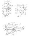
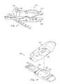
- FIG. 10is a perspective view of a motion preserving prosthetic device according to another embodiment of the present disclosure.
- FIG. 11is a lateral view of the motion preserving prosthetic device of FIG. 10 .
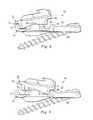
- FIG. 12is a lateral view of a motion preserving prosthetic device according to another embodiment of the present disclosure.
- FIG. 13is a lateral view of the motion preserving prosthetic device of FIG. 10 implanted in a spinal joint.
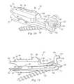
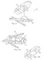
- FIG. 14is a perspective view of a motion preserving prosthetic device according to another embodiment of the present disclosure.
- FIG. 15-17are perspective views of motion preserving prosthetic devices according to other embodiments of the present disclosure.
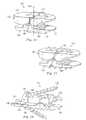
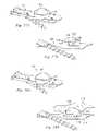
- FIG. 18-21are exploded views of motion preserving prosthetic devices according to other embodiments of the present disclosure.
- FIG. 22Ais a perspective view of a motion preserving prosthetic device according to another embodiment of the present disclosure.
- FIG. 22Bis a bottom perspective view of one aspect of the motion preserving prosthetic device of FIG. 22A .
- FIGS. 23-25are perspective views of motion preserving prosthetic devices according to other embodiments of the present disclosure.
- FIG. 26Ais a portion of a motion preserving prosthetic device according to another embodiment of the present disclosure.
- FIG. 26Bis a cross sectional view of the motion preserving prosthetic device of FIG. 26A .
- FIG. 27Ais a portion of a motion preserving prosthetic device according to another embodiment of the present disclosure.
- FIG. 27Bis a cross sectional view of the motion preserving prosthetic device of FIG. 27A .
- FIG. 28Ais a portion of a motion preserving prosthetic device according to another embodiment of the present disclosure.
- FIG. 28Bis a cross sectional view of the motion preserving prosthetic device of FIG. 27A .
- the present disclosurerelates generally to systems and methods for spinal surgery and, more particularly in some embodiments, to spinal arthroplasty systems and methods for posterior implantation.
- spinal arthroplasty systems and methods for posterior implantationFor the purposes of promoting an understanding of the principles of the invention, reference will now be made to embodiments or examples illustrated in the drawings, and specific language will be used to describe the same. It will nevertheless be understood that no limitation of the scope of the invention is thereby intended. Any alteration and further modifications in the described embodiments, and any further applications of the principles of the invention as described herein are contemplated as would normally occur to one skilled in the art to which the disclosure relates.
- FIG. 1a sagittal view of a vertebral column 10 is shown, illustrating a sequence of vertebrae V 1 , V 2 , V 3 , V 4 separated by natural intervertebral discs D 1 , D 2 , D 3 , respectively.
- the illustrationgenerally depicts a lumbar section of a spinal column, it is understood that the devices, systems, and methods of this disclosure may also be applied to all regions of the vertebral column, including thoracic and cervical regions.
- a vertebral joint 12 of the vertebral column 10includes the adjacent vertebrae V 1 , V 2 between which the intervertebral disc D 1 extends.
- the vertebra V 1includes a generally cylindrical vertebral body portion 14 , an inferior articular process 16 , and an inferior endplate 18 .
- the vertebra V 2includes a generally cylindrical vertebral body portion 20 , a superior articular process 22 , and a superior endplate 24 .
- a longitudinal axis 19extends through the centers of the cylindrical vertebral body portions 14 , 20 .
- a pedicle 25extends between the vertebral body portion 20 and superior articular process 22 .
- the inferior articular process 16 and the superior articular process 22form a facet or zygapophyseal joint 26 .
- the facet joint 26has a fluid filled capsule and cartilage to provide articulating surfaces for the articular processes 16 , 22 .
- Both the disc D 1 and the facet joint 26permit motion between adjacent bone surfaces, allowing the total vertebral joint 12 a normal range of flexion/extension, lateral bending, and rotational motion.
- all or portions of the disc, the facet joint, and/or the articular processes 16 , 22may be removed and replaced by a prosthetic device which may preserve motion in the spinal joint 12 .
- a second bilateral prosthetic devicemay also be used to replace a portion of the function of disc D 1 and the function of a second facet joint opposite the facet joint 26 .
- a prosthetic device 30may preserve motion in the spinal joint 12 .
- the prosthetic device 30includes an upper joint component 32 and a lower joint component 34 .
- the upper joint component 32includes an articulation surface 36 which may be smooth, concave, and generally spherical in shape.
- the lower joint component 34includes an articulation surface 38 which may be smooth, convex, and generally spherical in shape. As assembled, the articulation surface 36 may engage the articulation surface 38 to produce a ball-and-socket style anterior joint.
- a “spherical” shaped surfaceis understood to include any curved surface having a uniform radius of curvature and may refer to a spherical cap or a segment of a sphere.
- non-spherical curved surfacesmay function as articulation surfaces to impart specific limits to the range of motion of the prosthetic device.
- the jointmay be inverted with the upper articulation surface having a convex shape and the lower articulation surface having a concave articulation surface.
- the upper joint component 32may further include bumpers or motion limiters 40 , 42 which in this embodiment are recessed shoulders.
- the lower joint component 34includes bumpers or motion limiters 44 , 46 which in this embodiment are upwardly protruding extensions, spaced apart from the articulation surface 38 .
- the pair of motion limiters 40 , 44 and the pair of motion limiters 42 , 46may serve to constrain flexion/extension motion to a desirable range, preventing or limiting the dislocation of the joint formed by the articulation surfaces 36 , 38 .
- the motion limitersmay be shaped to provide a greater or lesser range of flexion/extension motion. For example, a surface on the motion limiter 44 angled away from the articulation surface 38 may permit greater flexion motion than would a motion limiter surface parallel to the axis 19 .
- the upper joint component 32may further include an outer contact surface 48 for interfacing with the vertebral endplate 18
- the lower joint component 34may include an outer contact surface 50 for interfacing with the vertebral endplate 24 .
- the upper joint component 32may further include an upper keel 52 extending from the outer contact surface 48 and comprising an elongated portion 53 and an elongated portion 54 .
- the elongated portion 54may be taller than the elongated portion 53 to provide the prosthetic device 30 with greater stability in the hard cortical bone of the outer wall of the vertebral body 14 .
- the raised keel portion 54has a sharpened and undercut leading edge 56 to encourage aggressive cutting of a channel in the vertebral body 14 and endplate 18 and to help prevent the device 30 from skiving off the vertebral body 14 .
- the raised keel portion 54is approximately one-third the length of the upper keel 52 and extends to the posterior edge of the upper joint component to provide additional stability.
- the upper keelmay be longer or shorter to achieve desired stability.
- the lower joint component 34may include a lower keel 58 extending from the outer contact surface 50 .
- the width of the keelmay vary.
- the lower portion of the keelmay be narrower than the taller portion of the keel.
- the keelmay taper or have an undulating wave form.
- the keelmay be perforated or porous to promote bone ingrowth.
- the upper joint component 32may further include a posterior tab 60 extending upward from the posterior edge of the outer contact surface 48 .
- the tab 60may be generally perpendicular or slightly acutely angled relative to the contact surface 48 .
- the tab 60may be integrally formed with or otherwise abut the posterior end of the upper keel 52 .
- the posterior tab 60may serve as a stop to prevent the device 30 from being inserted too far anteriorly into the intervertebral disc space.
- the position of the tab 60may be monitored with fluoroscopy or other visualization methods during surgery to determine the progress of the implantation and to confirm when the device 30 has been completely implanted with the posterior tab 60 in contact with a posterior wall of the vertebral body 14 .
- the location of the posterior tab 60may serve as an indicator of the location of the center of rotation.
- the upper joint component 32may be selected so that as the posterior tab 60 is positioned against the posterior wall of the vertebral body 14 , the center of rotation is moved into the desired predetermined location.
- the prosthetic device 30may further include a bridge component 62 extending posteriorly from the lower joint component 34 .
- the bridge component 62may further extend posteriorly from the intervertebral disc space between the vertebral bodies 14 , 20 and along at least a portion of the pedicle 25 to a distal end 64 .
- all or a portion of the pedicle 25may be removed leaving the bridge with little or no support from natural structures.
- the distal end 64 of the bridge 62may include a connection component 66 which in this embodiment is a passage for accepting a fastener 68 .
- the fastener 68is a bone screw, however in alternative embodiments, fasteners such as nails, staples, or other mechanical or chemical fasteners may be suitable.
- the orientation of the connection component 66permits the fastener 68 to become inserted extrapedicularly such that the screw travels a path obliquely angled or skewed away from a central axis defined through a pedicle.
- the fastener 68may be threaded across the a portion of the pedicle 25 and into the vertebral body 20 .
- Extrapedicular fixationmay be any fixation into the pedicle that does not follow a path down a central axis defined generally posterior-anterior through the pedicle.
- the screwpasses through an upper wall of the pedicle and may achieve strong cortical fixation.
- the fastenersmay be at least partially recessed so as not to interfere with articulations, soft tissues, and neural structures.
- the bridge 62 and the fastener 68may limit excessive movement of the device 30 , particularly during flexion/extension motions. Additionally, the bridge 62 may distribute the loads on the lower vertebra V 2 , reducing the potential for subsidence of the lower joint component 34 into the vertebral body 20 .
- connection component 66further includes a locking clip 70 which in this embodiment is an elastically deformable C-shaped structure which holds the fastener 68 in place, resisting any backward disengagement of the fastener 68 , particularly when the joint 12 is in motion.
- the locking clipmay be a cap, a clamp, an adhesive, or other suitable mechanical or chemical systems for limiting movement of the fastener 68 .
- the size and shape of the joint components 32 , 34 and the bridge component 62may be limited by the constraints of a posterior surgical approach.
- the anterior joint components 32 , 34may be configured to cover a maximum vertebral endplate area to dissipate loads and reduce subsidence while still fitting through the posterior surgical exposure, Kambin's triangle, and other neural elements.
- the material of the anterior joint components 32 , 34may extend anteriorly from the articulation surfaces 36 , 38 , respectively.
- the width of the bridge component 62is also minimized to pass through Kambin's triangle and to co-exist with the neural elements.
- the upper and lower joint componentsmay be provided in various heights.
- the height of the upper componentmay be increased by manufacturing the component with a thickened contact surface.
- materialmay be added to increase the overall height of the lower component.
- Providing the components in a variety of selectable heightsmay allow the surgeon to create the appropriate tension within the joint to both promote bone growth into the upper and lower components and to achieve a desired range of motion.
- the heights of the upper and lower joint componentsmay increase or decrease along the length of the component to create a desired lordosis or kyphosis.
- the ability to modify the resulting angle between the upper and lower contact surfacesmay allow the surgeon to address variations among patient anatomies or between levels of the vertebral column, such as at the lumbosacral joint (L5-S1). Allowing the surgeon to vary the height, angulation, and performance of the prosthetic device based on the vertebral level or the patient's anatomy may ensure a better fit and a better prognosis for the patient.
- the prosthetic device 30may be formed of any suitable biocompatible material including metals such as cobalt-chromium alloys, titanium alloys, nickel titanium alloys, and/or stainless steel alloys. Ceramic materials such as aluminum oxide or alumnia, zirconium oxide or zirconia, compact of particulate diamond, and/or pyrolytic carbon may also be suitable. Polymer materials may also be used, including any member of the polyaryletherketone (PAEK) family such as polyetheretherketone (PEEK), carbon-reinforced PEEK, or polyetherketoneketone (PEKK); polysulfone; polyetherimide; polyimide; ultra-high molecular weight polyethylene (UHMWPE); and/or cross-linked UHMWPE.
- the various components comprising the prosthetic device 30may be formed of different materials thus permitting metal on metal, metal on ceramic, metal on polymer, ceramic on ceramic, ceramic on polymer, or polymer on polymer constructions.
- Bone contacting surfaces of the prosthetic device 30including contact surfaces 48 , 50 ; keels 52 , 58 ; and bridge 62 may include features or coatings which enhance the fixation of the implanted prosthesis.
- the surfacesmay be roughened such as by chemical etching, bead-blasting, sanding, grinding, serrating, and/or diamond-cutting. All or a portion of the bone contacting surfaces of the prosthetic device 30 may also be coated with a biocompatible and osteoconductive material such as hydroxyapatite (HA), tricalcium phosphate (TCP), and/or calcium carbonate to promote bone in growth and fixation.
- HAhydroxyapatite
- TCPtricalcium phosphate
- osteoinductive coatingssuch as proteins from transforming growth factor (TGF) beta superfamily, or bone-morphogenic proteins, such as BMP2 or BMP7, may be used.
- TGFtransforming growth factor
- BMP2 or BMP7bone-morphogenic proteins
- suitable featuresmay include spikes, ridges, and/or other surface textures.
- the prosthetic device 30may be installed between the vertebrae V 1 , V 2 as will be described below.
- the prosthetic device 30may be implanted into a patient using a posterior transforaminal approach similar to the known TLIF (transforaminal lumbar interbody fusion) or PLIF (posterior lumbar interbody fusion) procedures.
- PLIF style approachesare generally more medial and rely on more retraction of the traversing root and dura to access the vertebral disc space. The space between these structures is known as Kambin's triangle.
- TLIF approachesare typically more oblique, requiring less retraction of the exiting root, and less epidural bleeding with less retraction of the traversing structures.
- an incisionsuch as a midline incision, may be made in the patient's back and some or all of the affected disc D 1 and surrounding tissue may be removed via the foramina.
- the superior endplate 24 of the vertebra V 2may be milled, rasped, or otherwise resected to match the profile of the outer contact surface 50 of the lower joint component 34 to normalize stress distributions on the endplate 24 , and/or to provide initial fixation prior to bone ingrowth.
- the preparation of the endplate 24 of vertebra V 2may result in a flattened surface or in surface contours such as pockets, grooves, or other contours that may match corresponding features on the outer contact surface 50 .
- the inferior endplate 18 of the vertebra V 1may be similarly prepared to receive the upper joint component 32 to the extent allowed by the exiting nerve root and the dorsal root ganglia. Depending on whether the facet joint 26 is being replaced, the natural facet joint and the corresponding articular processes 16 , 22 may be trimmed to make room for the bridge component 62 .
- the prosthetic device 30may then be inserted piecewise through the surgically created opening. That is, components of the prosthetic device 30 , including the upper and lower joint components 32 , 34 may be fit through the foramina and placed in the intervertebral disc space between the vertebral bodies 14 , 20 .
- the pieces of the prosthetic device 30may be completely separated or two or more of them may be tied or packaged together prior to insertion through the foramina by cloth or other materials known in the art.
- the lower joint componentmay be inserted such that it abuts a corresponding portion of the annulus.
- the endplates 18 , 24may be milled, chiseled, notched, or otherwise prepared to accept keels 52 , 58 , respectively. Alternatively, all or portions of the keels may self cut a channel in the endplates.
- the leading elongated portion 52may follow a pre-cut channel or may itself form the channel as it is driven into the endplate 18 .
- the leading edge 56may further cut the harder cortical bone of the periphery of the vertebral body 14 .
- the upper joint component 32may be driven until the posterior tab 60 contacts the posterior wall of the vertebra 14 , limiting further insertion.
- the lower joint component 34 with keel 58may be driven in a similar manner into the endplate 24 and vertebral body 20 .
- the upper joint component 32is held in place, at least initially, by a friction fit.
- fastenerssuch as bone screws, staples, adhesives or other mechanical or chemical fasteners may be used to hold the upper joint component in place.
- the articulation surface 36may be placed into articulating engagement with the articulation surface 38 .
- the center of rotation of the joint formed by the articulation surfaces 36 , 38may be located posteriorly of the central axis 19 extending longitudinally through the intervertebral disc space between vertebrae V 1 , V 2 . Because the posterior tab 60 serves as a stop to prevent over insertion of the upper joint component 32 , the final location of the center of rotation may be predetermined by the selection of the upper articulation component.
- the bridge 62may extend posteriorly from the lower joint components 34 and posteriorly from the intervertebral disc space between vertebral bodies 14 , 20 .
- the fastener 68may be inserted through the connection component 66 , through a portion of the pedicle 25 and into the vertebral body 20 .
- the fastener 68is drilled into the pedicle 25 at an oblique angle relative to the axis of the pedicle and thus is driven into the vertebral body 20 at an angle oblique to the axis 19 .
- the angle of the fastener 68may serve to limit the fastener from backing out of the bone during later motion of the joint 12 . Back out may be further limited by the locking clip 70 which clamps the fastener 68 to the distal end of the bridge 62 .
- a second prosthetic devicemay be inserted through a bilaterally opposite TLIF or PLIF type approach in substantially the same manner that has been described above. After insertion, the second prosthetic device may work in concert with the prosthetic device 30 and in a substantially similar manner to provide the range of motion to be described below.
- the anterior ball and socket type joint created by the articulation surfaces 36 , 38may be relatively stable and self-centering.
- the spherical surfaces of the articulation surfacespermit a full range of motion, including flexion/extension, lateral bending, and rotational motion.
- Both the anterior joint created by the articulation surfaces 36 , 38 and the fastener 68allow the prosthetic device 30 to resist shear forces, particularly anterior-posterior forces. Movement of the upper joint component 32 relative to the lower joint component 34 may be limited by the displacement of the articulation surface 38 within the articulation surface 36 .
- Rotational motion about the longitudinal axis 19may be limited by the combined constraint provided by the bilateral pair of prosthetic devices.
- the keels 52 , 58may further serve to resist shear and rotational motion of the individual components 32 , 34 .
- the function of the facet joint 26 to limit flexion/extension motion in the spinal joint 12may be restored, at least in part, by the motion limiters 40 , 42 , 44 , 46 .
- the motion limiters 40 , 44may come into contact to prevent further flexion motion and/or to prevent dislocation of the articulation surfaces 36 , 38 .
- the motion limiters 42 , 46may come into contact to prevent further extension motion and/or to prevent dislocation of the articulation surfaces 36 , 38 .
- Flexion/extension motionmay be further limited by the bridge 62 held in contact with the pedicle 25 and/or the vertebral body 20 by the fastener 68 .
- a simple, anteriorly located ball and socket jointwhich is tightly constrained with each component having the same or similar radii of curvature may allow flexion-extension, lateral bending, and torsion motions while resisting shear forces and limiting translation. Changing the shape of or clearance between the ball and socket components will also permit additional degrees of motion.
- a prosthetic device 80may preserve motion in the spinal joint 12 .
- the prosthetic device 80includes an upper joint component 82 and a lower joint component 84 .
- the upper joint component 82includes an articulation surface 86 which may be smooth, concave, and generally spherical in shape.
- the lower joint component 84includes an articulation surface 88 which may be smooth, convex, and generally spherical in shape. As assembled, the articulation surface 86 may engage the articulation surface 88 to produce a ball-and-socket style anterior joint.
- a “spherical” shaped surfaceis understood to include any curved surface having a uniform radius of curvature and may refer to a spherical cap or a segment of a sphere.
- non-spherical curved surfacesmay function as articulation surfaces to impart specific limits to the range of motion of the prosthetic device.
- the jointmay be inverted with the upper articulation surface having a convex shape and the lower articulation surface having a concave articulation surface.
- the upper joint component 82may further include an outer contact surface 90 for interfacing with the vertebral endplate 18
- the lower joint component 34may include an outer contact surface 92 for interfacing with the vertebral endplate 24 .
- the upper joint component 82may further include an upper keel 94 extending from the outer contact surface 90 and comprising an elongated portion 96 and an elongated portion 98 .
- the elongated portion 98may be taller than the elongated portion 96 to provide the prosthetic device 80 with greater stability in the hard cortical bone of the outer wall of the vertebral body 14 .
- the raised keel portion 98has a sharpened leading edge 100 to cut a channel in the vertebral body 14 and endplate 18 and to help prevent the device 80 from skiving off the vertebral body 14 .
- the raised keel portion 98is approximately one-third the length of the upper keel 94 and extends to the posterior edge of the upper joint component 82 to provide additional stability.
- the upper keelmay be longer or shorter.
- the lower joint component 84may include a lower keel 102 extending from the outer contact surface 92 .
- the upper joint component 82may further include a posterior tab 104 extending upward from the posterior edge of the outer contact surface 90 .
- the tab 104may be generally perpendicular or slightly acutely angled relative to the contact surface 90 .
- the tab 104may be integrally formed with or otherwise abut the posterior end of the upper keel 94 .
- the posterior tab 104may serve as a stop to prevent the device 80 from being inserted too far anteriorly into the intervertebral disc space.
- the position of the tab 104may be monitored with fluoroscopy or other visualization methods during surgery to determine the progress of the implantation and to confirm when the device 80 has been completely implanted with the posterior tab 104 in contact with a posterior wall of the vertebral body 14 . Because the position of the posterior tab 104 may be fixed relative to a center of rotation of the joint formed by articulation surfaces 86 , 88 , the location of the posterior tab 104 may serve as an indicator of the location of the center of rotation. After the surgeon has determined the desired location for the center of rotation, the upper joint component 82 may be selected so that as the posterior tab 104 is positioned against the posterior wall of the vertebral body 14 , the center of rotation is moved into the desired predetermined location.
- the prosthetic device 80may further include a lower bridge component 106 extending posteriorly from the lower joint component 84 . As installed, the lower bridge component 106 may further extend posteriorly from the intervertebral disc space between the vertebral bodies 14 , 20 and along at least a portion of the pedicle 25 .
- a lower posterior joint component 108may extend from the lower bridge 106 .
- the posterior joint component 108may include a post 110 having a bridge end 112 and a tail end 114 .
- the post 110may be configured to extend generally in a direction along the spinal column.
- the bridge end 112 of the post 110may connect to the lower bridge 106 .
- the post 110may extend upwardly so that the tail end 114 of the post 60 may be disposed at a location higher than the lower bridge 106 .
- the tail end 114may include a motion stop 116 configured to limit the range of articulation between the upper and lower joint components 82 , 84 .
- the post 110may include a straight segment extending between the bridge end 112 and the tail end 114 .
- the post 110may include a curve concentric with the curvature of the articulation surface 88 .
- the prosthetic device 80may further include an upper bridge component 118 extending posteriorly from the upper joint component 82 .
- the upper bridge component 118may further extend posteriorly from the intervertebral disc space between the vertebral bodies 14 , 20 .
- Either of the bridges components 106 , 118 , but particularly the lower bridge 106may be a “super” or artificial pedicle which may supplement or replace a natural pedicle.
- An upper posterior joint component 120extends from the upper bridge 118 .
- the upper posterior joint component 120includes a pair of arms 122 configured to form a C-shape that is adapted to receive the post 110 of the lower posterior joint component 108 .
- a portion of the arms 122form a motion stop 124 that is configured to cooperate with the motion stop 116 on the post 110 . Accordingly, when the upper and lower posterior joint components 108 , 120 are assembled as shown in FIGS. 10 and 11 , the motion stop 124 and the motion stop 116 cooperate to limit the range of articulation of the prosthetic device 80 .
- the upper bridge component 118may further include a motion limiter 125 which in this embodiment is a triangular extension that limits anterior motion of the post 110 .
- a connection component 126which in this embodiment is an integrally formed tube for accepting a fastener 128 , may extend between an opening 130 in the post 110 through the lower bridge component 106 .
- the fastener 128is a bone screw, however in alternative embodiments, fasteners such as nails, staples, or other mechanical or chemical fasteners may be suitable.
- the fastener 128may be threaded at an oblique angle across the a portion of the pedicle 25 and into the vertebral body 20 .
- the lower bridge 106 and the fastener 128may limit excessive movement of the device 80 , particularly during flexion/extension motions. Additionally, the lower bridge 106 may distribute the loads on the lower vertebra V 2 , reducing the potential for subsidence of the lower joint component 84 into the vertebral body 20 .
- the components of the prosthetic device 80may be formed of any of the materials listed above for device 30 .
- the prosthetic device 80may be implanted in a manner similar to that described above for device 30 , however in this embodiment, the components may be preassembled before implantation such that the post 110 is inserted through the arms 122 and permitted to translate.
- the prosthetic device 80may be paired with a similar or identical bilateral device.
- the anterior ball and socket type joint created by the articulation surfaces 86 , 88may be relatively stable and self-centering.
- the spherical surfaces of the articulation surfacespermit a full range of motion, including flexion/extension, lateral bending, and rotational motion.
- the anterior joint created by the articulation surfaces 86 , 88 ; the posterior joint created by the upper and lower posterior joint components 108 , 120 ; and the fastener 68allow the prosthetic device to resist shear forces, particularly anterior-posterior forces. Movement of the upper joint component 32 relative to the lower joint component 34 may be limited by the displacement of the articulation surface 38 within the articulation surface 36 and further by the posterior joint components 108 , 120 .
- Rotational motion about the longitudinal axis 19may be limited by the posterior joint components 108 , 120 and the combined constraint provided by the bilateral pair of prosthetic devices.
- the keels 94 , 102may further serve to resist shear and rotational motion of the individual components 82 , 84 .
- the function of the facet joint 26 to limit flexion/extension motion in the spinal joint 12may be restored, at least in part, by the posterior joint components 108 , 120 .
- additional flexion and dislocation of the anterior jointmay be limited by the cooperation of the motion stop 124 and the motion stop 116 .
- additional extension and dislocation of the anterior jointmay be limited by cooperation of the motion limiter 125 with the post 110 and by the cooperation of the upper bridge component 118 with the connection component 126 .
- Flexion/extension motionmay be further limited by the lower bridge 106 held in contact with the pedicle 25 and/or the vertebral body 20 by the fastener 128 .
- a prosthetic device 140may be substantially similar to the prosthetic device 80 , however in this embodiment a keel 142 may include an extended portion 146 and an extended portion 148 .
- the extended portion 148may be taller than the extended portion 146 and may include an undercut portion 150 to permit aggressive cutting of the vertebral body 14 during implantation.
- a prosthetic device 160may preserve motion in the spinal joint 12 .
- the prosthetic device 160includes an upper joint component 162 and a lower joint component 164 .
- the upper joint component 162includes an articulation surface 166 which may be smooth, concave, and generally spherical in shape.
- the lower joint component 164includes an articulation surface 168 which may be smooth, convex, and generally spherical in shape.
- the articulation surface 166may engage the articulation surface 168 to produce a ball-and-socket style anterior joint.
- the center of rotation of the ball-and-socket style anterior jointis positioned posteriorly of a geometric midline 169 . As installed, this posteriorly oriented center of rotation may generate more natural dynamics in the vertebral joint 12 .
- a “spherical” shaped surfaceis understood to include any curved surface having a uniform radius of curvature and may refer to a spherical cap or a segment of a sphere.
- non-spherical curved surfacesmay function as articulation surfaces to impart specific limits to the range of motion of the prosthetic device.
- the jointmay be inverted with the upper articulation surface having a convex shape and the lower articulation surface having a concave articulation surface.
- the upper joint component 162may further include an outer contact surface 170 for interfacing with the vertebral endplate 18
- the lower joint component 34may include an outer contact surface 172 for interfacing with the vertebral endplate 24 .
- the upper joint component 162may further include an upper keel 174 extending from the outer contact surface 170 .
- a greater portion of the keel 174may extend anteriorly of the midline 169 than extends posteriorly. This anterior orientation of the keel 174 may enhance the purchase of the upper joint component during movement in the joint 12 and may serve to resist otherwise undesirable excessive motion that would be created in the anterior of the device 160 by the posterior orientation of the center of rotation of the ball-and-socket joint.
- the upper keelmay be longer or shorter.
- the lower joint component 164may include a lower keel 176 extending from the outer contact surface 172 .
- the components of the prosthetic device 160may be formed of any of the materials listed above for device 30 .
- the prosthetic device 160may be implanted in a manner similar to that described above for device 30 , however in this embodiment, the entire device 160 may be positioned within the intervertebral disc space between the vertebral bodies 14 , 20 .
- the prosthetic device 80may be paired with a similar or identical bilateral device.
- the anterior ball and socket type joint created by the articulation surfaces 166 , 168may be relatively stable and self-centering.
- the spherical surfaces of the articulation surfacespermit a full range of motion, including flexion/extension, lateral bending, and rotational motion.
- this embodimentlacks posterior components substantially extending from the intervertebral disc space, the natural facet joint 26 may be preserved or may be replaced or augmented by other systems known in the art.
- Rotational motion about the longitudinal axis 19may be limited by the combined constraint provided by the bilateral pair of prosthetic devices.
- the keels 174 , 176may further serve to resist shear and rotational motion of the individual components 162 , 164 .
- a prosthetic device 180may preserve motion in the spinal joint 12 .
- the prosthetic device 180includes an upper joint component 182 and a lower joint component 184 .
- the device 180may be substantially similar to the device 160 with the exception that the upper joint component 182 includes a keel system 186 that includes a series of saw-toothed projections for anchoring into the vertebral endplate 18 .
- a similar keel system 188extends from the lower joint component 184 .
- the peaks and widths of the saw-tooth projectionsmay be uniform or may vary across the length of the keel system.
- a prosthetic device 190may preserve motion in the spinal joint 12 .
- the prosthetic device 190includes an upper joint component 192 and a lower joint component 194 .
- the device 190may be substantially similar to the device 160 with the differences to be described below.
- the prosthetic device 190may further include a bridge component 196 extending posteriorly from the lower joint component 194 .
- the bridge component 196may further extend posteriorly from the intervertebral disc space between the vertebral bodies 14 , 20 and along at least a portion of the pedicle 25 to a distal end 198 .
- all or a portion of the pedicle 25may be removed leaving the bridge with little or no support from natural structures.
- connection component 200which in this embodiment is a passage for accepting a fastener 202 .
- the fastener 202is a bone screw, however in alternative embodiments, fasteners such as nails, staples, or other mechanical or chemical fasteners may be suitable.
- the orientation of the connection component 200permits the fastener 202 to become inserted extrapedicularly such that the screw travels a path obliquely angled or skewed away from a central axis defined through a pedicle.
- the fastener 202may be threaded across the a portion of the pedicle 25 and into the vertebral body 20 .
- Extrapedicular fixationmay be any fixation into the pedicle that does not follow a path down a central axis defined generally posterior-anterior through the pedicle.
- the screwpasses through an upper wall of the pedicle and may achieve strong cortical fixation.
- the fastenersmay be at least partially recessed so as not to interfere with articulations, soft tissues, and neural structures.
- the bridge 196 and the fastener 202may limit excessive movement of the device 190 , particularly during flexion/extension motions. Additionally, the bridge 196 may distribute the loads on the lower vertebra V 2 , reducing the potential for subsidence of the lower joint component 194 into the vertebral body 20 .
- the connection componentmay include a locking clip or other suitable mechanical or chemical systems for limiting movement and disengagement of the fastener 202 .
- the upper joint component 192may also include a connection component which, similar to the posterior tab 60 of the device 30 , extends generally upward from the upper surface of the upper joint component 192 .
- the connection component 192includes a through passage 206 sized to receive a fastener 208 .
- the connection component 192may serve as both an insertion stop as the upper joint component 192 is inserted into the intervertebral disc space and as an entry point for directing the fastener 208 into the vertebral body 14 .
- the fastener 208may limit posterior migration and/or dislocation of the upper joint component 192 and may also limit excessive movement of the device 190 , particularly during flexion/extension motion. Locking clips or other blocking devices may be used to prevent the fastener 208 from becoming disengaged.
- the size and shape of the connection componentmay be varied.
- the connection componentmay be a U-shaped recess still sized to accept a fastener or may include multiple passages to accept a staple or multiple fasteners.
- a prosthetic device 210may preserve motion in the spinal joint 12 .
- the prosthetic device 210includes an upper joint component 212 and a lower joint component 214 .
- the device 210may be substantially similar to the device 190 , with the exception that in this embodiment, the upper joint component fastener may be omitted.
- the upper joint component 212may include a connection component 216 having a through passage 218 .
- the omission of the upper fastenermay serve to eliminate unnecessary constraint in the anterior joint formed by the upper and lower joint components.
- the passage 218unoccupied by a fastener, may permit bone ingrowth, allowing the upper joint component 212 to become fixed to the vertebra V 1 over time.
- a prosthetic device 220may preserve motion in the spinal joint 12 .
- the prosthetic device 220includes an upper joint component 222 and a lower joint component 224 .
- the device 220may be substantially similar to the device 190 and may further include features not shown in detail for device 190 .
- the upper joint component 222includes an articulation surface 226 which may be smooth, concave, and generally spherical in shape.
- the lower joint component 224includes an articulation surface 228 which may be smooth, convex, and generally spherical in shape. As assembled, the articulation surface 226 may engage the articulation surface 228 to produce a ball-and-socket style anterior joint.
- a projection 230may extend from the articulation surface 226 . In this embodiment the projection 230 is arched or “rocker” shaped with a narrower width in the lateral dimension than the length in the anterior/posterior dimension.
- a recess or slot 232may extend into the articulation surface 228 .
- the length of the slot 232may extend in a generally anterior/posterior direction with the length of the slot being greater than the width of the slot.
- the base of the slot 232is curved to generally match the shape of the projection 230 .
- the base of the slotmay be flat.
- the projection 230is sized to cooperate with the slot 232 to permit flexion/extension motion in the anterior joint while resisting shear forces and torsional motion at the anterior joint.
- the projection and the slotmay be shaped to permit other types of motion in the anterior joint.
- a slot wider than the projectionmay permit some torsion or translation between the articulation surfaces.
- a projection having a more cylindrical-type shapemay permit torsional motion with restricting anterior/posterior translation and joint dislocation.
- the lower joint component 224may further include a restraint slot 234 to receive a locking clip (not shown), as described above for FIG. 3 , to prevent a bone fastener from backing out from the bone.
- a prosthetic device 240may preserve motion in the spinal joint 12 .
- the prosthetic device 240includes an upper joint component 242 and a lower joint component 244 .
- the device 220may be substantially similar to the device 190 with differences to be described as follows.
- the upper joint component 222includes a recess 246 which may be arched shaped and located posteriorly of the primary spherical articulation joint.
- the lower joint component 224includes an arched shaped projection 248 also located posteriorly of the primary spherical articulation joint and sized to fit within the recess 246 .
- the projection 248is inserted inside the recess 246 to resist dislocation and to resist undesirable motion. This configuration serves to resist both anterior/posterior and lateral shear forces and to resist torsion while permitting freedom in flexion/extension motion. Also, the tighter the fit between the projection and the recess, the more lateral bending will be restricted.
- FIG. 20depicts a device 250 that may be substantially similar to the device 240 , however in this embodiment, a projection 254 is inserted into a recess 252 , with both the projection and the recess located anteriorly of the primary spherical articulation joint.
- This configurationserves to resist both anterior/posterior and lateral shear forces and to resist torsion while permitting freedom in flexion/extension motion. Also, the tighter the fit between the projection and the recess, the more lateral bending will be restricted.
- a prosthetic device 260may preserve motion in the spinal joint 12 .
- the prosthetic device 260includes an upper joint component 262 and a lower joint component 264 .
- the device 260may be substantially similar to the device 220 however the projection 266 extending from the articulation surface of the upper joint component 262 may be cylindrical and sized to be received into a mating cylindrical opening in the lower articulation surface of the lower joint component 264 .
- This embodimentmay resist shear forces and dislocation while permitting torsional motion.
- a prosthetic device 270may preserve motion in the spinal joint 12 .
- the prosthetic device 270includes an upper joint component 272 and a lower joint component 274 .
- the devicemay be substantially similar to the device 240 with the differences to be described.
- a pair of bumpers 276extend from the lower joint component 274 , one to the anterior side of the articulation joint and another to the posterior side of the articulation joint.
- the bumpers 276are generally cylindrical but in alternative embodiments may be spherical, domed shaped or any other suitable shape to provide dampening.
- a pair of recesses 278extend into the upper joint component 272 . As shown, the recesses may be wider than the bumpers 276 to permit more torsional range of motion and more lateral bending.
- the bumpers 276may extend into the respective recesses 278 and serve to dampen or cushion the motion between the upper and lower joint components 272 , 274 .
- the bumpersmay be formed of a rigid material as are the projections 248 , 254 , in this embodiment, the bumpers are formed of an elastomeric material or any other resilient material that may provide dampening between the joint components, especially during flexion/extension motion.
- mechanical springs or other mechanical dampenersmay be provided between the upper and lower joint components.
- a prosthetic device 280may preserve motion in the spinal joint 12 .
- the prosthetic device 280includes an upper joint component 282 and a lower joint component 284 .
- the device 280may be substantially similar to the device 160 however, in this embodiment, a connection arm 286 extends from the upper joint component 282 .
- the connection arm 286may be formed of a rigid material such as a metal or a polymer. In alternative embodiments, flexibility in the connection arm may be permitted.
- the connection arm 286includes a collar 288 for connection to an elongate rod 290 which may be formed from a rigid material such as titanium or from a more flexible material such as PEEK. In the embodiment of FIG.
- the rod 290extends between a pair of polyaxial bone screws 292 , 294 .
- the prosthetic device 280may be used with any rod and screw system known in the art to provide additional constraint at the vertebral joint.
- a spacer 296may extend between the collar 288 of the connection arm 286 .
- the spacer 296may serve to maintain a desired distance between the connection arm 286 and the polyaxial screw 292 .
- the spacer 296may be deformable and resilient such that the collar 288 may compress the spacer under certain types of motion such as flexion/extension.
- the spacermay be relatively rigid, creating a fixed spacing between the collar and the polyaxial screw.
- a prosthetic device 300may preserve motion in the spinal joint 12 .
- the prosthetic device 300includes an upper joint component 302 and a lower joint component 304 .
- the device 300may be substantially similar to the device 280 however in this embodiment, a connection arm 306 extends from the lower joint component 304 .
- a spacer 308extends between the connection arm 306 and a polyaxial screw 310 .
- a prosthetic device 310comprises an upper joint component (not shown) and a lower joint component 312 .
- the device 300may be substantially similar to the device 190 with the differences to be explained.
- a convex lower articulation surface component 314is separate from the lower joint component 312 .
- a washer 316extends between the lower articulation surface component 314 and the lower joint component 312 to provide a cushioning effect to the lower articulation surface.
- the lower articulation surface componentcomprises a protrusion 318 that is sized to fit within a recess 320 in the washer 316 to connect the articulation surface component and the washer.
- the washer 316is further sized to fit within a recess 322 in the lower joint component 312 .
- the washermay be formed of a resilient and deformable material such as an elastomer to provide a cushioning effect during flexion/extension, lateral bending, and rotation.
- the material for forming the washermay be relatively rigid and selected for its load bearing and wear-resistant properties.
- polyurethanemay be a suitable material.
- the articulation surface componentmay be rotatable relative to the washer or may be fixed.
- the washermay be rotatable relative to the lower joint component or may be fixed.
- the washer 316permits the articulation surface component 314 to move relative to the lower joint component 312 while providing some constraint on the motion of the articulation surface component. As the resilience of the material of the washer increases, the constraint on the motion of the articulation surface component may decrease.
- a prosthetic devicemay comprise a lower joint component 330 .
- an articulation surface component 332extends through a washer 334 and into contact with the lower joint component 330 .
- the washer 334comprises an opening 336 to receive and hold a protrusion 338 of the articulation surface component 332 .
- the articulation surface component 332may be pivotable within the washer and may be cushioned by the washer along an outer periphery. As described above, this washer also provides a cushioning effect to the articulation surface component while constraining some motion of the articulation surface component during flexion/extension, lateral bending, and rotational motion.
- a washer 340extends between an articulation surface component 342 and a lower joint component 344 .
- the articulation surface component 342does not contact the lower joint component 344 , but rather is completely cushioned by the washer 340 .
- the washer 340has side walls 346 which extend along the outer periphery of the articulation surface component 342 and which may serve as a bumper between the lower joint component 344 and an upper joint component 348 .
- upper and lowerare used in some embodiments to describe the position of components of the embodiments. While upper is typically used to describe positions toward the head and lower is used to describe positions toward the tail or foot, as used herein, upper and lower are used simply as modifiers for the relative locations of components of the illustrated embodiments. Components labeled as upper or lower to describe an illustrated embodiment are not intended to limit the orientation of a device or application of a method relative to a patient's anatomy, or to limit the scope of claims to any device or method.
- the described embodimentsgenerally involve integral formation of the anterior joint components, the bridge and the posterior joint components, it is understood that in alternative embodiments, the components may be modular to accommodate different patient anatomies and to facilitate minimally invasive implantation.
Landscapes
- Health & Medical Sciences (AREA)
- Orthopedic Medicine & Surgery (AREA)
- Engineering & Computer Science (AREA)
- Biomedical Technology (AREA)
- Neurology (AREA)
- Life Sciences & Earth Sciences (AREA)
- Animal Behavior & Ethology (AREA)
- Veterinary Medicine (AREA)
- Public Health (AREA)
- Heart & Thoracic Surgery (AREA)
- General Health & Medical Sciences (AREA)
- Cardiology (AREA)
- Vascular Medicine (AREA)
- Transplantation (AREA)
- Oral & Maxillofacial Surgery (AREA)
- Surgery (AREA)
- Nuclear Medicine, Radiotherapy & Molecular Imaging (AREA)
- Medical Informatics (AREA)
- Molecular Biology (AREA)
- Prostheses (AREA)
- Surgical Instruments (AREA)
Abstract
Description
- U.S. Utility patent application Ser. No. 11/031,602, filed on Jan. 7, 2005 and entitled “Spinal Arthroplasty Device and Method;”
- U.S. Utility patent application Ser. No. 11/031,603, filed on Jan. 7, 2005 and entitled “Dual Articulating Spinal Device and Method;”
- U.S. Utility patent application Ser. No. 11/031,780, filed on Jan. 7, 2005 and entitled “Split Spinal Device and Method;”
- U.S. Utility patent application Ser. No. 11/031,904, filed on Jan. 7, 2005 and entitled “Interconnected Spinal Device and Method;”
- U.S. Utility patent application Ser. No. 11/031,700, filed on Jan. 7, 2005 and entitled “Support Structure Device and Method;”
- U.S. Utility patent application Ser. No. 11/031,783, filed on Jan. 7, 2005 and entitled “Mobile Bearing Spinal Device and Method;”
- U.S. Utility patent application Ser. No. 11/031,781, filed on Jan. 7, 2005 and entitled “Centrally Articulating Spinal Device and Method;”
- U.S. Utility patent application Ser. No. 11/031,903, filed on Jan. 7, 2005 and entitled “Posterior Spinal Device and Method;”
- U.S. Utility patent application Ser. No. 11/342,961, filed on Jan. 30, 2006 and entitled “Prosthetic Device for Spinal Joint Reconstruction;”
- U.S. Utility patent application Ser. No. 11/343,159, filed on Jan. 30, 2006 and entitled “Posterior Joint Replacement Device;” and
- U.S. Utility patent application Ser. No. 11/494,311, filed on Jul. 27, 2006 and entitled “Prosthetic Device for Spinal Joint Reconstruction.”
Claims (14)
Priority Applications (16)
| Application Number | Priority Date | Filing Date | Title |
|---|---|---|---|
| US11/839,821US8864832B2 (en) | 2007-06-20 | 2007-08-16 | Posterior total joint replacement |
| EP08756608AEP2170224B1 (en) | 2007-06-20 | 2008-06-02 | Posterior total joint replacement |
| AT08756608TATE536837T1 (en) | 2007-06-20 | 2008-06-02 | POSTERIOR TOTAL JOINT REPLACEMENT |
| JP2010510549AJP2011504377A (en) | 2007-06-20 | 2008-06-02 | Total posterior joint replacement |
| PCT/US2008/065504WO2008151115A2 (en) | 2007-06-01 | 2008-06-02 | Posterior total joint replacement |
| CN200880019129.XACN102131480B (en) | 2007-06-20 | 2008-06-02 | Posterior total joint replacement |
| KR1020097027661AKR20100032868A (en) | 2007-06-01 | 2008-06-02 | Posterior total joint replacement |
| AU2008259888AAU2008259888B2 (en) | 2007-06-01 | 2008-06-02 | Posterior total joint replacement |
| CN201410148201.6ACN103908359A (en) | 2007-06-20 | 2008-06-02 | Posterior total joint replacement |
| US14/486,065US9770338B2 (en) | 2007-06-20 | 2014-09-15 | Posterior total joint replacement |
| US15/712,046US10631995B2 (en) | 2007-06-20 | 2017-09-21 | Posterior total joint replacement |
| US15/955,611US10821003B2 (en) | 2007-06-20 | 2018-04-17 | Spinal osteotomy |
| US16/836,915US11918479B2 (en) | 2007-06-20 | 2020-04-01 | Posterior total joint replacement |
| US17/023,864US11890202B2 (en) | 2007-06-20 | 2020-09-17 | Spinal osteotomy |
| US18/373,185US20240016621A1 (en) | 2007-06-20 | 2023-09-26 | Spinal motion restoration |
| US18/594,385US20240197492A1 (en) | 2007-06-20 | 2024-03-04 | Posterior total joint replacement |
Applications Claiming Priority (2)
| Application Number | Priority Date | Filing Date | Title |
|---|---|---|---|
| US75708407A | 2007-06-20 | 2007-06-20 | |
| US11/839,821US8864832B2 (en) | 2007-06-20 | 2007-08-16 | Posterior total joint replacement |
Related Parent Applications (1)
| Application Number | Title | Priority Date | Filing Date |
|---|---|---|---|
| US75708407AContinuation | 2007-06-01 | 2007-06-20 |
Related Child Applications (1)
| Application Number | Title | Priority Date | Filing Date |
|---|---|---|---|
| US14/486,065DivisionUS9770338B2 (en) | 2007-06-20 | 2014-09-15 | Posterior total joint replacement |
Publications (2)
| Publication Number | Publication Date |
|---|---|
| US20080300685A1 US20080300685A1 (en) | 2008-12-04 |
| US8864832B2true US8864832B2 (en) | 2014-10-21 |
Family
ID=40089134
Family Applications (5)
| Application Number | Title | Priority Date | Filing Date |
|---|---|---|---|
| US11/839,821Active2032-06-07US8864832B2 (en) | 2007-06-01 | 2007-08-16 | Posterior total joint replacement |
| US14/486,065Active2028-04-11US9770338B2 (en) | 2007-06-20 | 2014-09-15 | Posterior total joint replacement |
| US15/712,046ActiveUS10631995B2 (en) | 2007-06-20 | 2017-09-21 | Posterior total joint replacement |
| US16/836,915Active2029-10-25US11918479B2 (en) | 2007-06-20 | 2020-04-01 | Posterior total joint replacement |
| US18/594,385PendingUS20240197492A1 (en) | 2007-06-20 | 2024-03-04 | Posterior total joint replacement |
Family Applications After (4)
| Application Number | Title | Priority Date | Filing Date |
|---|---|---|---|
| US14/486,065Active2028-04-11US9770338B2 (en) | 2007-06-20 | 2014-09-15 | Posterior total joint replacement |
| US15/712,046ActiveUS10631995B2 (en) | 2007-06-20 | 2017-09-21 | Posterior total joint replacement |
| US16/836,915Active2029-10-25US11918479B2 (en) | 2007-06-20 | 2020-04-01 | Posterior total joint replacement |
| US18/594,385PendingUS20240197492A1 (en) | 2007-06-20 | 2024-03-04 | Posterior total joint replacement |
Country Status (8)
| Country | Link |
|---|---|
| US (5) | US8864832B2 (en) |
| EP (1) | EP2170224B1 (en) |
| JP (1) | JP2011504377A (en) |
| KR (1) | KR20100032868A (en) |
| CN (2) | CN103908359A (en) |
| AT (1) | ATE536837T1 (en) |
| AU (1) | AU2008259888B2 (en) |
| WO (1) | WO2008151115A2 (en) |
Cited By (12)
| Publication number | Priority date | Publication date | Assignee | Title |
|---|---|---|---|---|
| US20180008426A1 (en)* | 2007-06-20 | 2018-01-11 | Hh Spinal Llc | Posterior total joint replacement |
| US9956087B2 (en) | 2015-07-17 | 2018-05-01 | Globus Medical, Inc | Intervertebral spacer and plate |
| US9987144B2 (en) | 2015-07-17 | 2018-06-05 | Globus Medical, Inc. | Intervertebral spacer and plate |
| US10016282B2 (en) | 2015-07-17 | 2018-07-10 | Globus Medical, Inc. | Intervertebral spacer and plate |
| US20180228619A1 (en)* | 2007-06-20 | 2018-08-16 | International Surgical Sezc | Spinal osteotomy |
| US10258482B1 (en) | 2017-11-07 | 2019-04-16 | Uki Llc | Artificial intervertebral implant |
| US10376377B2 (en) | 2015-07-17 | 2019-08-13 | Globus Medical, Inc. | Intervertebral spacer and plate |
| US10537667B2 (en) | 2015-01-28 | 2020-01-21 | Ethicon Llc | High temperature material for use in medical devices |
| US10874521B2 (en) | 2017-11-07 | 2020-12-29 | Uki Llc | Artificial intervertebral implant |
| EP3612115A4 (en)* | 2017-04-17 | 2021-01-20 | Marc Peterman | Spinal osteotomy |
| US11045326B2 (en) | 2015-07-17 | 2021-06-29 | Global Medical Inc | Intervertebral spacer and plate |
| US12064354B2 (en) | 2020-09-24 | 2024-08-20 | Alphatec Spine, Inc. | Composite porous interbodies and methods of manufacture |
Families Citing this family (138)
| Publication number | Priority date | Publication date | Assignee | Title |
|---|---|---|---|---|
| FR2897259B1 (en) | 2006-02-15 | 2008-05-09 | Ldr Medical Soc Par Actions Si | INTERSOMATIC TRANSFORAMINAL CAGE WITH INTERBREBAL FUSION GRAFT AND CAGE IMPLANTATION INSTRUMENT |
| FR2824261B1 (en) | 2001-05-04 | 2004-05-28 | Ldr Medical | INTERVERTEBRAL DISC PROSTHESIS AND IMPLEMENTATION METHOD AND TOOLS |
| FR2827156B1 (en) | 2001-07-13 | 2003-11-14 | Ldr Medical | VERTEBRAL CAGE DEVICE WITH MODULAR FASTENING |
| US6793678B2 (en) | 2002-06-27 | 2004-09-21 | Depuy Acromed, Inc. | Prosthetic intervertebral motion disc having dampening |
| FR2846550B1 (en) | 2002-11-05 | 2006-01-13 | Ldr Medical | INTERVERTEBRAL DISC PROSTHESIS |
| FR2858546B1 (en) | 2003-08-04 | 2006-04-28 | Spine Next Sa | INTERVERTEBRAL DISC PROSTHESIS |
| US7753958B2 (en) | 2003-08-05 | 2010-07-13 | Gordon Charles R | Expandable intervertebral implant |
| US7799082B2 (en) | 2003-08-05 | 2010-09-21 | Flexuspine, Inc. | Artificial functional spinal unit system and method for use |
| US7771479B2 (en) | 2004-01-09 | 2010-08-10 | Warsaw Orthopedic, Inc. | Dual articulating spinal device and method |
| US20050171608A1 (en) | 2004-01-09 | 2005-08-04 | Sdgi Holdings, Inc. | Centrally articulating spinal device and method |
| FR2865629B1 (en) | 2004-02-04 | 2007-01-26 | Ldr Medical | INTERVERTEBRAL DISC PROSTHESIS |
| EP2113227B1 (en) | 2004-02-04 | 2015-07-29 | LDR Medical | Intervertebral disc prosthesis |
| FR2869528B1 (en) | 2004-04-28 | 2007-02-02 | Ldr Medical | INTERVERTEBRAL DISC PROSTHESIS |
| WO2006058221A2 (en) | 2004-11-24 | 2006-06-01 | Abdou Samy M | Devices and methods for inter-vertebral orthopedic device placement |
| FR2879436B1 (en) | 2004-12-22 | 2007-03-09 | Ldr Medical | INTERVERTEBRAL DISC PROSTHESIS |
| FR2891135B1 (en) | 2005-09-23 | 2008-09-12 | Ldr Medical Sarl | INTERVERTEBRAL DISC PROSTHESIS |
| FR2893838B1 (en) | 2005-11-30 | 2008-08-08 | Ldr Medical Soc Par Actions Si | PROSTHESIS OF INTERVERTEBRAL DISC AND INSTRUMENTATION OF INSERTION OF THE PROSTHESIS BETWEEN VERTEBRATES |
| US7914580B2 (en) | 2006-11-07 | 2011-03-29 | Biomedflex Llc | Prosthetic ball-and-socket joint |
| US7905919B2 (en) | 2006-11-07 | 2011-03-15 | Biomedflex Llc | Prosthetic joint |
| US8029574B2 (en) | 2006-11-07 | 2011-10-04 | Biomedflex Llc | Prosthetic knee joint |
| US8070823B2 (en) | 2006-11-07 | 2011-12-06 | Biomedflex Llc | Prosthetic ball-and-socket joint |
| US9005307B2 (en) | 2006-11-07 | 2015-04-14 | Biomedflex, Llc | Prosthetic ball-and-socket joint |
| WO2008058205A1 (en) | 2006-11-07 | 2008-05-15 | Biomedflex, Llc | Medical implants |
| US8308812B2 (en) | 2006-11-07 | 2012-11-13 | Biomedflex, Llc | Prosthetic joint assembly and joint member therefor |
| US20110166671A1 (en) | 2006-11-07 | 2011-07-07 | Kellar Franz W | Prosthetic joint |
| US8512413B2 (en) | 2006-11-07 | 2013-08-20 | Biomedflex, Llc | Prosthetic knee joint |
| WO2008070863A2 (en) | 2006-12-07 | 2008-06-12 | Interventional Spine, Inc. | Intervertebral implant |
| US20080161929A1 (en) | 2006-12-29 | 2008-07-03 | Mccormack Bruce | Cervical distraction device |
| US8465546B2 (en) | 2007-02-16 | 2013-06-18 | Ldr Medical | Intervertebral disc prosthesis insertion assemblies |
| FR2916956B1 (en) | 2007-06-08 | 2012-12-14 | Ldr Medical | INTERSOMATIC CAGE, INTERVERTEBRAL PROSTHESIS, ANCHORING DEVICE AND IMPLANTATION INSTRUMENTATION |
| US8900307B2 (en) | 2007-06-26 | 2014-12-02 | DePuy Synthes Products, LLC | Highly lordosed fusion cage |
| US8187330B2 (en) | 2007-10-22 | 2012-05-29 | Flexuspine, Inc. | Dampener system for a posterior stabilization system with a variable length elongated member |
| US8157844B2 (en) | 2007-10-22 | 2012-04-17 | Flexuspine, Inc. | Dampener system for a posterior stabilization system with a variable length elongated member |
| US8523912B2 (en) | 2007-10-22 | 2013-09-03 | Flexuspine, Inc. | Posterior stabilization systems with shared, dual dampener systems |
| US8267965B2 (en) | 2007-10-22 | 2012-09-18 | Flexuspine, Inc. | Spinal stabilization systems with dynamic interbody devices |
| US8182514B2 (en) | 2007-10-22 | 2012-05-22 | Flexuspine, Inc. | Dampener system for a posterior stabilization system with a fixed length elongated member |
| US8162994B2 (en) | 2007-10-22 | 2012-04-24 | Flexuspine, Inc. | Posterior stabilization system with isolated, dual dampener systems |
| WO2009089367A2 (en) | 2008-01-09 | 2009-07-16 | Providence Medical Technology, Inc. | Methods and apparatus for accessing and treating the facet joint |
| EP2237748B1 (en) | 2008-01-17 | 2012-09-05 | Synthes GmbH | An expandable intervertebral implant |
| US8936641B2 (en) | 2008-04-05 | 2015-01-20 | DePuy Synthes Products, LLC | Expandable intervertebral implant |
| CA2725811A1 (en) | 2008-06-06 | 2009-12-10 | Providence Medical Technology, Inc. | Facet joint implants and delivery tools |
| US8267966B2 (en) | 2008-06-06 | 2012-09-18 | Providence Medical Technology, Inc. | Facet joint implants and delivery tools |
| US11224521B2 (en) | 2008-06-06 | 2022-01-18 | Providence Medical Technology, Inc. | Cervical distraction/implant delivery device |
| US9333086B2 (en) | 2008-06-06 | 2016-05-10 | Providence Medical Technology, Inc. | Spinal facet cage implant |
| US20100087923A1 (en)* | 2008-08-23 | 2010-04-08 | Abdou M Samy | Implants for facet joint repair and methods use |
| US9526620B2 (en) | 2009-03-30 | 2016-12-27 | DePuy Synthes Products, Inc. | Zero profile spinal fusion cage |
| CN105326585B (en) | 2009-09-17 | 2018-12-11 | Ldr控股公司 | Intervertebral implant with extensible bone anchoring element |
| US8979927B2 (en)* | 2009-11-18 | 2015-03-17 | Innovasis, Inc. | Spinal implant with staples |
| US8764806B2 (en) | 2009-12-07 | 2014-07-01 | Samy Abdou | Devices and methods for minimally invasive spinal stabilization and instrumentation |
| US9393129B2 (en) | 2009-12-10 | 2016-07-19 | DePuy Synthes Products, Inc. | Bellows-like expandable interbody fusion cage |
| WO2011080535A1 (en) | 2009-12-31 | 2011-07-07 | Lrd Medical | Anchoring device, intervertebral implant and implantation instrument |
| WO2014015309A1 (en) | 2012-07-20 | 2014-01-23 | Jcbd, Llc | Orthopedic anchoring system and methods |
| CA3002234C (en) | 2010-01-13 | 2020-07-28 | Jcbd, Llc | Sacroiliac joint fixation fusion system |
| US9333090B2 (en) | 2010-01-13 | 2016-05-10 | Jcbd, Llc | Systems for and methods of fusing a sacroiliac joint |
| US9381045B2 (en) | 2010-01-13 | 2016-07-05 | Jcbd, Llc | Sacroiliac joint implant and sacroiliac joint instrument for fusing a sacroiliac joint |
| US9421109B2 (en) | 2010-01-13 | 2016-08-23 | Jcbd, Llc | Systems and methods of fusing a sacroiliac joint |
| US8377139B2 (en) | 2010-06-17 | 2013-02-19 | Aesculap Implant Systems, Llc | Standalone interbody fusion device with locking and release mechanism |
| US8979860B2 (en) | 2010-06-24 | 2015-03-17 | DePuy Synthes Products. LLC | Enhanced cage insertion device |
| US9907560B2 (en) | 2010-06-24 | 2018-03-06 | DePuy Synthes Products, Inc. | Flexible vertebral body shavers |
| US8623091B2 (en) | 2010-06-29 | 2014-01-07 | DePuy Synthes Products, LLC | Distractible intervertebral implant |
| CN103228233B (en)* | 2010-10-06 | 2015-11-25 | 卡琳·比特纳-扬茨 | Prosthesis for cervical and lumbar vertebrae |
| US9402732B2 (en) | 2010-10-11 | 2016-08-02 | DePuy Synthes Products, Inc. | Expandable interspinous process spacer implant |
| US8394129B2 (en) | 2011-03-10 | 2013-03-12 | Interventional Spine, Inc. | Method and apparatus for minimally invasive insertion of intervertebral implants |
| US8518087B2 (en) | 2011-03-10 | 2013-08-27 | Interventional Spine, Inc. | Method and apparatus for minimally invasive insertion of intervertebral implants |
| US8388687B2 (en) | 2011-03-25 | 2013-03-05 | Flexuspine, Inc. | Interbody device insertion systems and methods |
| EP2720628B1 (en) | 2011-06-17 | 2021-08-11 | Jcbd, Llc | Sacroiliac joint implant system |
| US9820864B2 (en) | 2011-09-01 | 2017-11-21 | In Queue Innovations, Llc | Disc replacement device and method of use |
| US8845728B1 (en) | 2011-09-23 | 2014-09-30 | Samy Abdou | Spinal fixation devices and methods of use |
| US9526627B2 (en) | 2011-11-17 | 2016-12-27 | Exactech, Inc. | Expandable interbody device system and method |
| US9198764B2 (en)* | 2012-01-31 | 2015-12-01 | Blackstone Medical, Inc. | Intervertebral disc prosthesis and method |
| US20130226240A1 (en) | 2012-02-22 | 2013-08-29 | Samy Abdou | Spinous process fixation devices and methods of use |
| FR2987256B1 (en) | 2012-02-24 | 2014-08-08 | Ldr Medical | ANCHORING DEVICE FOR INTERVERTEBRAL IMPLANT, INTERVERTEBRAL IMPLANT AND IMPLANTATION INSTRUMENTATION |
| AU2013282268A1 (en) | 2012-06-29 | 2015-01-22 | DePuy Synthes Products, LLC | Lateral insertion spinal implant |
| EP2877127B1 (en) | 2012-07-26 | 2019-08-21 | Synthes GmbH | Expandable implant |
| US9198767B2 (en) | 2012-08-28 | 2015-12-01 | Samy Abdou | Devices and methods for spinal stabilization and instrumentation |
| US20140067069A1 (en) | 2012-08-30 | 2014-03-06 | Interventional Spine, Inc. | Artificial disc |
| AU2013308332B2 (en) | 2012-08-31 | 2017-01-19 | Newsouth Innovations Pty Limited | Bone stabilization device and methods of use |
| WO2015028853A1 (en) | 2013-08-30 | 2015-03-05 | Newsouth Innovations Pty Limited | Spine stabilization device |
| US9320617B2 (en) | 2012-10-22 | 2016-04-26 | Cogent Spine, LLC | Devices and methods for spinal stabilization and instrumentation |
| USD732667S1 (en) | 2012-10-23 | 2015-06-23 | Providence Medical Technology, Inc. | Cage spinal implant |
| US9492288B2 (en) | 2013-02-20 | 2016-11-15 | Flexuspine, Inc. | Expandable fusion device for positioning between adjacent vertebral bodies |
| US9717601B2 (en) | 2013-02-28 | 2017-08-01 | DePuy Synthes Products, Inc. | Expandable intervertebral implant, system, kit and method |
| US9522070B2 (en) | 2013-03-07 | 2016-12-20 | Interventional Spine, Inc. | Intervertebral implant |
| US9277928B2 (en) | 2013-03-11 | 2016-03-08 | Interventional Spine, Inc. | Method and apparatus for minimally invasive insertion of intervertebral implants |
| US9993353B2 (en) | 2013-03-14 | 2018-06-12 | DePuy Synthes Products, Inc. | Method and apparatus for minimally invasive insertion of intervertebral implants |
| US9700356B2 (en) | 2013-07-30 | 2017-07-11 | Jcbd, Llc | Systems for and methods of fusing a sacroiliac joint |
| US9826986B2 (en) | 2013-07-30 | 2017-11-28 | Jcbd, Llc | Systems for and methods of preparing a sacroiliac joint for fusion |
| US9510872B2 (en) | 2013-03-15 | 2016-12-06 | Jcbd, Llc | Spinal stabilization system |
| US9717539B2 (en) | 2013-07-30 | 2017-08-01 | Jcbd, Llc | Implants, systems, and methods for fusing a sacroiliac joint |
| EP2777628B1 (en)* | 2013-03-15 | 2018-02-28 | Neos Surgery, S.L. | Device for repairing an intervertebral disc |
| US10245087B2 (en) | 2013-03-15 | 2019-04-02 | Jcbd, Llc | Systems and methods for fusing a sacroiliac joint and anchoring an orthopedic appliance |
| FR3005569B1 (en) | 2013-05-16 | 2021-09-03 | Ldr Medical | VERTEBRAL IMPLANT, VERTEBRAL IMPLANT FIXATION DEVICE AND IMPLANTATION INSTRUMENTATION |
| FR3016793B1 (en) | 2014-01-30 | 2021-05-07 | Ldr Medical | ANCHORING DEVICE FOR SPINAL IMPLANT, SPINAL IMPLANT AND IMPLANTATION INSTRUMENTATION |
| US10365936B2 (en)* | 2014-02-27 | 2019-07-30 | Red Hat Israel, Ltd. | Idle processor management by guest in virtualized systems |
| US10398565B2 (en) | 2014-04-24 | 2019-09-03 | Choice Spine, Llc | Limited profile intervertebral implant with incorporated fastening and locking mechanism |
| US9517144B2 (en) | 2014-04-24 | 2016-12-13 | Exactech, Inc. | Limited profile intervertebral implant with incorporated fastening mechanism |
| FR3020756B1 (en) | 2014-05-06 | 2022-03-11 | Ldr Medical | VERTEBRAL IMPLANT, VERTEBRAL IMPLANT FIXATION DEVICE AND IMPLANT INSTRUMENTATION |
| AU2015267055B2 (en) | 2014-05-27 | 2020-04-02 | Christopher U. Phan | Lateral mass fixation implant |
| US9801546B2 (en) | 2014-05-27 | 2017-10-31 | Jcbd, Llc | Systems for and methods of diagnosing and treating a sacroiliac joint disorder |
| JP2017520357A (en) | 2014-05-28 | 2017-07-27 | プロビデンス メディカル テクノロジー インコーポレイテッド | Outer mass fixing system |
| GB201416867D0 (en)* | 2014-09-24 | 2014-11-05 | Fitzbionics Ltd | A prosthetic intervertebral disc joint assembly |
| US10387178B2 (en)* | 2014-10-29 | 2019-08-20 | Red Hat Israel, Ltd. | Idle based latency reduction for coalesced interrupts |
| US11426290B2 (en) | 2015-03-06 | 2022-08-30 | DePuy Synthes Products, Inc. | Expandable intervertebral implant, system, kit and method |
| US9913727B2 (en) | 2015-07-02 | 2018-03-13 | Medos International Sarl | Expandable implant |
| US10857003B1 (en) | 2015-10-14 | 2020-12-08 | Samy Abdou | Devices and methods for vertebral stabilization |
| EP3474784A2 (en) | 2016-06-28 | 2019-05-01 | Eit Emerging Implant Technologies GmbH | Expandable and angularly adjustable intervertebral cages with articulating joint |
| US11510788B2 (en) | 2016-06-28 | 2022-11-29 | Eit Emerging Implant Technologies Gmbh | Expandable, angularly adjustable intervertebral cages |
| TW201806562A (en) | 2016-06-28 | 2018-03-01 | 普羅維登斯醫療科技公司 | Spinal implant and methods of using the same |
| CN106236332B (en)* | 2016-08-31 | 2018-07-20 | 北京爱康宜诚医疗器材有限公司 | Intervertebral disk prosthesis |
| IT201600105751A1 (en)* | 2016-10-20 | 2018-04-20 | Medacta Int Sa | INTERVERTEBRAL FUSION CAGE |
| US10973648B1 (en) | 2016-10-25 | 2021-04-13 | Samy Abdou | Devices and methods for vertebral bone realignment |
| US10744000B1 (en) | 2016-10-25 | 2020-08-18 | Samy Abdou | Devices and methods for vertebral bone realignment |
| US10537436B2 (en) | 2016-11-01 | 2020-01-21 | DePuy Synthes Products, Inc. | Curved expandable cage |
| US10888433B2 (en) | 2016-12-14 | 2021-01-12 | DePuy Synthes Products, Inc. | Intervertebral implant inserter and related methods |
| KR101952597B1 (en)* | 2017-02-13 | 2019-02-27 | (주)시지바이오 | Implant for bone substitute |
| US20230380984A1 (en)* | 2017-04-17 | 2023-11-30 | 3Spine, Inc | Total spinal joint systems with dissimilar bearing materials |
| US12370056B2 (en)* | 2017-04-17 | 2025-07-29 | 3Spine, Inc. | Devices and methods for altering spinal lateral curvature |
| US10398563B2 (en) | 2017-05-08 | 2019-09-03 | Medos International Sarl | Expandable cage |
| US11871968B2 (en) | 2017-05-19 | 2024-01-16 | Providence Medical Technology, Inc. | Spinal fixation access and delivery system |
| US11344424B2 (en) | 2017-06-14 | 2022-05-31 | Medos International Sarl | Expandable intervertebral implant and related methods |
| US10940016B2 (en) | 2017-07-05 | 2021-03-09 | Medos International Sarl | Expandable intervertebral fusion cage |
| US10603055B2 (en) | 2017-09-15 | 2020-03-31 | Jcbd, Llc | Systems for and methods of preparing and fusing a sacroiliac joint |
| US11648128B2 (en) | 2018-01-04 | 2023-05-16 | Providence Medical Technology, Inc. | Facet screw and delivery device |
| WO2020061464A1 (en) | 2018-09-21 | 2020-03-26 | Providence Medical Technology, Inc. | Vertebral joint access and decortication devices and methods of using |
| US11179248B2 (en) | 2018-10-02 | 2021-11-23 | Samy Abdou | Devices and methods for spinal implantation |
| US11446156B2 (en) | 2018-10-25 | 2022-09-20 | Medos International Sarl | Expandable intervertebral implant, inserter instrument, and related methods |
| CA3119074A1 (en)* | 2018-11-09 | 2020-05-14 | Marc Peterman | Intervertebral spinal implant and surgical methods |
| USD933230S1 (en) | 2019-04-15 | 2021-10-12 | Providence Medical Technology, Inc. | Cervical cage |
| EP3986336A4 (en)* | 2019-06-21 | 2023-07-19 | Providence Medical Technology, Inc. | SPINAL FACET JOINT IMPLANT AND RELATED INSTRUMENTS |
| US11452618B2 (en) | 2019-09-23 | 2022-09-27 | Dimicron, Inc | Spinal artificial disc removal tool |
| USD945621S1 (en) | 2020-02-27 | 2022-03-08 | Providence Medical Technology, Inc. | Spinal cage |
| US11426286B2 (en) | 2020-03-06 | 2022-08-30 | Eit Emerging Implant Technologies Gmbh | Expandable intervertebral implant |
| KR102217719B1 (en) | 2020-04-14 | 2021-02-18 | 힐로 이노베이션 | Lumbar Intervertebral Artificial Disc and the method of the Lumbar Intervertebral Artificial Disc insertion |
| US11850160B2 (en) | 2021-03-26 | 2023-12-26 | Medos International Sarl | Expandable lordotic intervertebral fusion cage |
| US11752009B2 (en) | 2021-04-06 | 2023-09-12 | Medos International Sarl | Expandable intervertebral fusion cage |
| US12090064B2 (en) | 2022-03-01 | 2024-09-17 | Medos International Sarl | Stabilization members for expandable intervertebral implants, and related systems and methods |
| US12409046B2 (en)* | 2022-04-12 | 2025-09-09 | 3Spine, Inc. | Total spinal joint systems with motion moderators |
| CN119868020B (en)* | 2025-02-06 | 2025-10-03 | 首都医科大学宣武医院 | A lumbar intervertebral disc prosthesis |
Citations (253)
| Publication number | Priority date | Publication date | Assignee | Title |
|---|---|---|---|---|
| US4349921A (en) | 1980-06-13 | 1982-09-21 | Kuntz J David | Intervertebral disc prosthesis |
| US4697586A (en) | 1986-06-24 | 1987-10-06 | Gazale William J | Combined chisel-guide surgical instrument |
| US4697582A (en) | 1983-10-28 | 1987-10-06 | Peze William | Appliance for correcting rachidial deformities |
| US4702930A (en) | 1984-12-28 | 1987-10-27 | Battelle-Institute E.V. | Method of producing implantable bone replacement materials |
| US4759769A (en) | 1987-02-12 | 1988-07-26 | Health & Research Services Inc. | Artificial spinal disc |
| US4836196A (en) | 1988-01-11 | 1989-06-06 | Acromed Corporation | Surgically implantable spinal correction system |
| US4932975A (en) | 1989-10-16 | 1990-06-12 | Vanderbilt University | Vertebral prosthesis |
| US5092866A (en) | 1989-02-03 | 1992-03-03 | Breard Francis H | Flexible inter-vertebral stabilizer as well as process and apparatus for determining or verifying its tension before installation on the spinal column |
| FR2676911A1 (en) | 1991-05-30 | 1992-12-04 | Psi Ste Civile Particuliere | INTERVERTEBRAL STABILIZATION DEVICE WITH SHOCK ABSORBERS. |
| US5258031A (en) | 1992-01-06 | 1993-11-02 | Danek Medical | Intervertebral disk arthroplasty |
| US5282863A (en) | 1985-06-10 | 1994-02-01 | Charles V. Burton | Flexible stabilization system for a vertebral column |
| US5370697A (en)* | 1992-04-21 | 1994-12-06 | Sulzer Medizinaltechnik Ag | Artificial intervertebral disk member |
| US5387213A (en) | 1991-02-05 | 1995-02-07 | Safir S.A.R.L. | Osseous surgical implant particularly for an intervertebral stabilizer |
| US5401269A (en) | 1992-03-13 | 1995-03-28 | Waldemar Link Gmbh & Co. | Intervertebral disc endoprosthesis |
| US5415661A (en) | 1993-03-24 | 1995-05-16 | University Of Miami | Implantable spinal assist device |
| US5423825A (en) | 1992-06-10 | 1995-06-13 | Levine; Andrew S. | Spinal fusion instruments and methods |
| US5443515A (en) | 1994-01-26 | 1995-08-22 | Implex Corporation | Vertebral body prosthetic implant with slidably positionable stabilizing member |
| US5458864A (en) | 1989-11-16 | 1995-10-17 | Nissan Chemical Industries Ltd. | Process for producing high-purity silica by reacting crude silica with ammonium fluoride |
| EP0677277A2 (en) | 1994-03-18 | 1995-10-18 | Patrice Moreau | Spinal prosthetic assembly |
| WO1996000049A1 (en) | 1994-06-24 | 1996-01-04 | Fairant, Paulette | Vertebral articular facet prostheses |
| US5507816A (en) | 1991-12-04 | 1996-04-16 | Customflex Limited | Spinal vertebrae implants |
| US5556431A (en) | 1992-03-13 | 1996-09-17 | B+E,Uml U+Ee Ttner-Janz; Karin | Intervertebral disc endoprosthesis |
| US5562737A (en) | 1993-11-18 | 1996-10-08 | Henry Graf | Extra-discal intervertebral prosthesis |
| US5562660A (en) | 1993-02-09 | 1996-10-08 | Plus Endoprothetik Ag | Apparatus for stiffening and/or correcting the vertebral column |
| US5562738A (en) | 1992-01-06 | 1996-10-08 | Danek Medical, Inc. | Intervertebral disk arthroplasty device |
| US5571109A (en) | 1993-08-26 | 1996-11-05 | Man Ceramics Gmbh | System for the immobilization of vertebrae |
| US5607425A (en) | 1993-10-08 | 1997-03-04 | Rogozinski; Chaim | Apparatus, method and system for the treatment of spinal conditions |
| US5672175A (en) | 1993-08-27 | 1997-09-30 | Martin; Jean Raymond | Dynamic implanted spinal orthosis and operative procedure for fitting |
| US5674296A (en) | 1994-11-14 | 1997-10-07 | Spinal Dynamics Corporation | Human spinal disc prosthesis |
| US5676701A (en) | 1993-01-14 | 1997-10-14 | Smith & Nephew, Inc. | Low wear artificial spinal disc |
| US5702450A (en) | 1993-06-28 | 1997-12-30 | Bisserie; Michel | Intervertebral disk prosthesis |
| US5728098A (en) | 1996-11-07 | 1998-03-17 | Sdgi Holdings, Inc. | Multi-angle bone screw assembly using shape-memory technology |
| US5752957A (en) | 1997-02-12 | 1998-05-19 | Third Millennium Engineering, Llc | Polyaxial mechanism for use with orthopaedic implant devices |
| US5772661A (en) | 1988-06-13 | 1998-06-30 | Michelson; Gary Karlin | Methods and instrumentation for the surgical correction of human thoracic and lumbar spinal disease from the antero-lateral aspect of the spine |
| US5895428A (en) | 1996-11-01 | 1999-04-20 | Berry; Don | Load bearing spinal joint implant |
| US5899941A (en) | 1997-12-09 | 1999-05-04 | Chubu Bearing Kabushiki Kaisha | Artificial intervertebral disk |
| USRE36221E (en) | 1989-02-03 | 1999-06-01 | Breard; Francis Henri | Flexible inter-vertebral stabilizer as well as process and apparatus for determining or verifying its tension before installation on the spinal column |
| US5928284A (en) | 1998-07-09 | 1999-07-27 | Mehdizadeh; Hamid M. | Disc replacement prosthesis |
| US5961516A (en) | 1996-08-01 | 1999-10-05 | Graf; Henry | Device for mechanically connecting and assisting vertebrae with respect to one another |
| WO1999053871A1 (en) | 1998-04-23 | 1999-10-28 | Cauthen Research Group, Inc. | Articulating spinal implant |
| US6019792A (en) | 1998-04-23 | 2000-02-01 | Cauthen Research Group, Inc. | Articulating spinal implant |
| WO2000004851A1 (en) | 1998-07-22 | 2000-02-03 | Spinal Dynamics Corporation | Threaded cylindrical multidiscoid single or multiple array disc prosthesis |
| US6036088A (en) | 1995-03-15 | 2000-03-14 | Hitachi, Ltd | Method and apparatus for processing IC card found |
| US6039763A (en) | 1998-10-27 | 2000-03-21 | Disc Replacement Technologies, Inc. | Articulating spinal disc prosthesis |
| US6042582A (en) | 1997-05-20 | 2000-03-28 | Ray; Charles D. | Instrumentation and method for facilitating insertion of spinal implant |
| USRE36758E (en) | 1995-03-16 | 2000-06-27 | Fitz; William R. | Artificial facet joint |
| US6106557A (en) | 1998-07-23 | 2000-08-22 | Howmedica Gmbh | Reconstruction system for vertebra |
| US6113637A (en) | 1998-10-22 | 2000-09-05 | Sofamor Danek Holdings, Inc. | Artificial intervertebral joint permitting translational and rotational motion |
| US6146421A (en) | 1997-08-04 | 2000-11-14 | Gordon, Maya, Roberts And Thomas, Number 1, Llc | Multiple axis intervertebral prosthesis |
| US6159211A (en) | 1998-10-22 | 2000-12-12 | Depuy Acromed, Inc. | Stackable cage system for corpectomy/vertebrectomy |
| US6159244A (en) | 1999-07-30 | 2000-12-12 | Suddaby; Loubert | Expandable variable angle intervertebral fusion implant |
| US6159214A (en) | 1996-07-31 | 2000-12-12 | Michelson; Gary K. | Milling instrumentation and method for preparing a space between adjacent vertebral bodies |
| US6174311B1 (en) | 1998-10-28 | 2001-01-16 | Sdgi Holdings, Inc. | Interbody fusion grafts and instrumentation |
| US6179875B1 (en) | 1998-06-17 | 2001-01-30 | Ulrich Gmbh & Co. Kg | Implant for fusing lumbar vertebrae and method of using same |
| US6190414B1 (en) | 1996-10-31 | 2001-02-20 | Surgical Dynamics Inc. | Apparatus for fusion of adjacent bone structures |
| US6193757B1 (en) | 1998-10-29 | 2001-02-27 | Sdgi Holdings, Inc. | Expandable intervertebral spacers |
| US6200322B1 (en) | 1999-08-13 | 2001-03-13 | Sdgi Holdings, Inc. | Minimal exposure posterior spinal interbody instrumentation and technique |
| US6224607B1 (en) | 1999-01-25 | 2001-05-01 | Gary K. Michelson | Instrumentation and method for creating an intervertebral space for receiving an implant |
| US6224599B1 (en) | 1999-05-19 | 2001-05-01 | Matthew G. Baynham | Viewable wedge distractor device |
| US6228118B1 (en) | 1997-08-04 | 2001-05-08 | Gordon, Maya, Roberts And Thomas, Number 1, Llc | Multiple axis intervertebral prosthesis |
| US6231609B1 (en) | 1998-07-09 | 2001-05-15 | Hamid M. Mehdizadeh | Disc replacement prosthesis |
| US6235059B1 (en) | 1996-04-03 | 2001-05-22 | Scient'x (Societe A Responsabilite Limitee) | Intersomatic setting and fusion system |
| US6241769B1 (en)* | 1998-05-06 | 2001-06-05 | Cortek, Inc. | Implant for spinal fusion |
| WO2001039678A1 (en) | 1999-12-01 | 2001-06-07 | Henry Graf | Intervertebral stabilising device |
| US6251112B1 (en) | 2000-04-18 | 2001-06-26 | Roger P. Jackson | Thin profile closure cap for open ended medical implant |
| WO2001045576A1 (en) | 1999-12-20 | 2001-06-28 | Synthes Ag Chur | Device for the stabilisation of two adjacent verterbral bodies of the spine |
| US20010005796A1 (en) | 1995-03-27 | 2001-06-28 | Thomas Zdeblick | Methods and instruments for interbody fusion |
| US20010010021A1 (en) | 1999-01-08 | 2001-07-26 | Boyd Lawrence M. | Flexible implant using partially demineralized bone |
| US6277122B1 (en) | 1999-10-15 | 2001-08-21 | Sdgi Holdings, Inc. | Distraction instrument with fins for maintaining insertion location |
| US20010016774A1 (en) | 1998-10-20 | 2001-08-23 | Bresina Stephen J. | Strain regulating fusion cage for spinal fusion surgery |
| US20010016773A1 (en) | 1998-10-15 | 2001-08-23 | Hassan Serhan | Spinal disc |
| US20010032020A1 (en) | 1999-07-02 | 2001-10-18 | Petrus Besselink | Reinforced expandable cage |
| US20010034553A1 (en) | 2000-02-04 | 2001-10-25 | Michelson Gary Karlin | Expandable push-in arcuate interbody spinal fusion implant with tapered configuration during insertion |
| US20010047207A1 (en) | 1998-10-30 | 2001-11-29 | Michelson Gary K. | Self-broaching, rotatable, push-in interbody spinal fusion implant and method for deployment thereof |
| US6325827B1 (en) | 1999-02-01 | 2001-12-04 | Blacksheep Technologies, Inc. | Intervertebral implant |
| US20010049560A1 (en) | 1998-01-30 | 2001-12-06 | Paul David C. | Intervertebral allograft spacer |
| US6368350B1 (en) | 1999-03-11 | 2002-04-09 | Sulzer Spine-Tech Inc. | Intervertebral disc prosthesis and method |
| US20020045943A1 (en) | 2000-10-17 | 2002-04-18 | Uk Chang Jong | Prosthetic device for correcting deformity of spine |
| US20020049394A1 (en) | 2000-08-25 | 2002-04-25 | The Cleveland Clinic Foundation | Apparatus and method for assessing loads on adjacent bones |
| US20020049497A1 (en) | 2000-10-11 | 2002-04-25 | Mason Michael D. | Graftless spinal fusion device |
| US20020052656A1 (en) | 2000-02-04 | 2002-05-02 | Michelson Gary Karlin | Expandable push-in interbody spinal fusion implant |
| US20020068977A1 (en) | 2000-12-05 | 2002-06-06 | Jackson Roger P. | Anterior variable expandable fusion cage |
| US20020068976A1 (en) | 2000-12-04 | 2002-06-06 | Jackson Roger P. | Posterior expandable fusion cage |
| US6402750B1 (en) | 2000-04-04 | 2002-06-11 | Spinlabs, Llc | Devices and methods for the treatment of spinal disorders |
| US20020077702A1 (en) | 2000-12-19 | 2002-06-20 | Cortek, Inc. | Dynamic implanted intervertebral spacer |
| WO2002047586A1 (en) | 2000-12-13 | 2002-06-20 | Eska Implants Gmbh & Co. | Partial intervertebral disk replacement implant |
| US6409766B1 (en) | 1998-07-30 | 2002-06-25 | Expanding Concepts, Llc | Collapsible and expandable interbody fusion device |
| US6419705B1 (en) | 1999-06-23 | 2002-07-16 | Sulzer Spine-Tech Inc. | Expandable fusion device and method |
| US6419703B1 (en) | 2001-03-01 | 2002-07-16 | T. Wade Fallin | Prosthesis for the replacement of a posterior element of a vertebra |
| US20020095155A1 (en) | 1994-03-28 | 2002-07-18 | Michelson Gary Karlin | Spinal implant containing bone morphogenetic protein |
| US20020107572A1 (en) | 2001-02-06 | 2002-08-08 | Foley Kevin T. | Spinal implant with attached ligament |
| US6432140B1 (en) | 1999-12-10 | 2002-08-13 | Chih-I Lin | Intervertebral retrieval device |
| FR2799638B1 (en) | 1999-10-14 | 2002-08-16 | Fred Zacouto | FIXATOR AND VERTEBRAL JOINT |
| US20020116065A1 (en) | 1998-10-21 | 2002-08-22 | Jackson Roger P. | Spinal fusion apparatus and method |
| US20020123806A1 (en) | 1999-10-22 | 2002-09-05 | Total Facet Technologies, Inc. | Facet arthroplasty devices and methods |
| US20020128713A1 (en) | 1999-08-13 | 2002-09-12 | Bret Ferree | Spinal fusion cage with lordosis correction |
| US20020128712A1 (en) | 2001-03-09 | 2002-09-12 | Michelson Gary K. | Expansion constraining member adapted for use with an expandable interbody spinal fusion implant |
| US20020133155A1 (en) | 2000-02-25 | 2002-09-19 | Ferree Bret A. | Cross-coupled vertebral stabilizers incorporating spinal motion restriction |
| US6454807B1 (en) | 2000-11-30 | 2002-09-24 | Roger P. Jackson | Articulated expandable spinal fusion cage system |
| US20020138143A1 (en) | 1997-08-27 | 2002-09-26 | Grooms Jamie M. | Cortical bone cervical Smith-Robinson fusion implant |
| US20020138146A1 (en) | 2000-04-18 | 2002-09-26 | Jackson Roger P. | Anterior expandable spinal fusion cage system |
| US20020143399A1 (en) | 2001-04-02 | 2002-10-03 | Ulrich Gmbh & Co. Kg | Anchorable vertebral implant |
| US20020151895A1 (en) | 2001-02-16 | 2002-10-17 | Soboleski Donald A. | Method and device for treating scoliosis |
| US20020156528A1 (en) | 1999-08-03 | 2002-10-24 | Michel Gau | Intervertebral nucleus prosthesis and surgical procedure for implanting the same |
| US20020161366A1 (en) | 2000-12-29 | 2002-10-31 | Bruce Robie | Instrument system for preparing a disc space between adjacent vertebral bodies to receive a repair device |
| US20020169508A1 (en) | 1998-06-18 | 2002-11-14 | Pioneer Laboratories, Inc. | Spinal fixation system |
| US20020183756A1 (en) | 2001-06-04 | 2002-12-05 | Michelson Gary K. | Dynamic, modular, single-lock anterior cervical plate system, having assembleable and moveable segments, instrumentation, and method for installation thereof |
| US20020193880A1 (en)* | 1999-11-24 | 2002-12-19 | Robert Fraser | Anterior lumbar interbody fusion cage with locking plate |
| US20030004572A1 (en) | 2001-03-02 | 2003-01-02 | Goble E. Marlowe | Method and apparatus for spine joint replacement |
| US20030009226A1 (en) | 1999-12-29 | 2003-01-09 | Henry Graf | Device and assembly for intervertebral stabilisation |
| US6514260B1 (en) | 2000-03-15 | 2003-02-04 | Sdgi Holdings, Inc. | Methods and instruments for laparoscopic spinal surgery |
| EP1281361A1 (en) | 2001-08-02 | 2003-02-05 | Lafitt, S.A. | Device to prevent intervertebral disk degeneration |
| US20030028250A1 (en) | 1999-10-22 | 2003-02-06 | Archus Orthopedics, Inc. | Prostheses, systems and methods for replacement of natural facet joints with artifical facet joint surfaces |
| US6517580B1 (en) | 2000-03-03 | 2003-02-11 | Scient'x Societe A Responsabilite Limited | Disk prosthesis for cervical vertebrae |
| DE10135771A1 (en) | 2001-07-23 | 2003-02-20 | Aesculap Ag & Co Kg | Vertebral facet joint implant comprises at least one fixing element with surfaces which are in full areal contact with at least one facet |
| US6524312B2 (en) | 2000-01-06 | 2003-02-25 | Spinal Concepts, Inc. | Instrument and method for implanting an interbody fusion device |
| US6527804B1 (en) | 1998-12-11 | 2003-03-04 | Dimso (Distribution Medicale Du Sud-Quest) | Intervertebral disk prosthesis |
| US6540747B1 (en) | 1999-04-16 | 2003-04-01 | Nuvasive, Inc. | System for securing joints together |
| US20030074068A1 (en) | 2001-07-16 | 2003-04-17 | Errico Joseph P. | Artificial intervertebral disc having limited rotation using a captured ball and socket joint with a solid ball and retaining cap |
| US20030078666A1 (en) | 2001-10-18 | 2003-04-24 | Ralph James D. | Intervertebral spacer device having a slotted partial circular domed arch strip spring |
| US6562074B2 (en) | 2001-10-17 | 2003-05-13 | Medicinelodge, Inc. | Adjustable bone fusion implant and method |
| US6565571B1 (en) | 1998-10-19 | 2003-05-20 | Scient'x | Anterior osteosynthesis plate for lumbar vertebrae or sacral lumbar vertebra and instrument for positioning same |
| US6565605B2 (en) | 2000-12-13 | 2003-05-20 | Medicinelodge, Inc. | Multiple facet joint replacement |
| WO2003041618A2 (en) | 2001-11-15 | 2003-05-22 | Louis Rene | Posterior vertebral joint prosthesis |
| US20030100949A1 (en) | 2000-04-19 | 2003-05-29 | Michelson Gary K. | Expandable threaded arcuate interbody spinal fusion implant with cylindrical configuration during insertion |
| US6572653B1 (en) | 2001-12-07 | 2003-06-03 | Rush E. Simonson | Vertebral implant adapted for posterior insertion |
| WO2003045262A2 (en) | 2001-11-30 | 2003-06-05 | Spine Next | Intervertebral implant with elastically deformable wedge |
| US6579319B2 (en) | 2000-11-29 | 2003-06-17 | Medicinelodge, Inc. | Facet joint replacement |
| US6582466B1 (en) | 1998-12-11 | 2003-06-24 | Stryker Spine | Intervertebral disc prosthesis with reduced friction |
| US6582468B1 (en) | 1998-12-11 | 2003-06-24 | Spryker Spine | Intervertebral disc prosthesis with compressible body |
| US20030135278A1 (en) | 2002-01-17 | 2003-07-17 | Concept Matrix, Llc | Intervertebral disk prosthesis |
| US20030139812A1 (en) | 2001-11-09 | 2003-07-24 | Javier Garcia | Spinal implant |
| US20030139813A1 (en) | 2001-05-03 | 2003-07-24 | Dominique Messerli | Intervertebral implant for transforaminal posterior lumbar interbody fusion procedure |
| US6599291B1 (en) | 2000-10-20 | 2003-07-29 | Sdgi Holdings, Inc. | Methods and instruments for interbody surgical techniques |
| US6610093B1 (en) | 2000-07-28 | 2003-08-26 | Perumala Corporation | Method and apparatus for stabilizing adjacent vertebrae |
| US6610091B1 (en) | 1999-10-22 | 2003-08-26 | Archus Orthopedics Inc. | Facet arthroplasty devices and methods |
| US20030171813A1 (en) | 2002-03-05 | 2003-09-11 | P. Douglas Kiester | Method and apparatus for providing an expandable spinal fusion cage |
| US20030176923A1 (en) | 2002-03-12 | 2003-09-18 | Waldemar Link Gmbh & Co. | Intervertebral prosthesis |
| WO2003084449A1 (en) | 2002-03-30 | 2003-10-16 | Cool Brace | Intervertebral device and method of use |
| US20030199982A1 (en) | 1998-09-04 | 2003-10-23 | Sdgi Holdings, Inc. | Peanut spectacle multi discoid thoraco-lumbar disc prosthesis |
| US20030199981A1 (en) | 2002-04-23 | 2003-10-23 | Ferree Bret A. | Artificial disc replacements with natural kinematics |
| US20030204261A1 (en) | 2002-04-25 | 2003-10-30 | Lukas Eisermann | Articular disc prosthesis and method for implanting the same |
| US20030204260A1 (en) | 2002-04-30 | 2003-10-30 | Ferree Bret A. | Methods and apparatus for preventing the migration of intradiscal devices |
| US20030204271A1 (en) | 2002-04-24 | 2003-10-30 | Ferree Bret A. | Check reins for artificial disc replacements |
| US6641582B1 (en) | 2000-07-06 | 2003-11-04 | Sulzer Spine-Tech Inc. | Bone preparation instruments and methods |
| US6641614B1 (en) | 1997-05-01 | 2003-11-04 | Spinal Concepts, Inc. | Multi-variable-height fusion device |
| US20030208273A1 (en) | 2002-01-09 | 2003-11-06 | Lukas Eisermann | Intervertebral prosthetic joint |
| US6648895B2 (en) | 2000-02-04 | 2003-11-18 | Sdgi Holdings, Inc. | Methods and instrumentation for vertebral interbody fusion |
| US20030233148A1 (en)* | 2002-04-23 | 2003-12-18 | Ferree Bret A. | Modular components to improve the fit of artificial disc replacements |
| US20030233146A1 (en)* | 2002-06-18 | 2003-12-18 | Alexander Grinberg | Intervertebral disc |
| US6669729B2 (en) | 2002-03-08 | 2003-12-30 | Kingsley Richard Chin | Apparatus and method for the replacement of posterior vertebral elements |
| US20040002762A1 (en) | 2002-06-27 | 2004-01-01 | Hawkins John Riley | Prosthetic intervertebral motion disc having dampening |
| US20040002712A1 (en) | 2002-06-26 | 2004-01-01 | Alexander Grinberg | Endplate shaping device |
| US6679915B1 (en) | 1998-04-23 | 2004-01-20 | Sdgi Holdings, Inc. | Articulating spinal implant |
| US6685742B1 (en) | 2002-11-12 | 2004-02-03 | Roger P. Jackson | Articulated anterior expandable spinal fusion cage system |
| US20040024462A1 (en) | 2002-04-12 | 2004-02-05 | Ferree Bret A. | Spacerless artificial disc replacements |
| US20040030390A1 (en) | 2002-04-23 | 2004-02-12 | Ferree Bret A. | Intradiscal component installation apparatus and methods |
| US20040030391A1 (en) | 2002-04-24 | 2004-02-12 | Bret Ferree | Artificial intervertebral disc spacers |
| US20040034430A1 (en) | 2002-06-14 | 2004-02-19 | Falahee Mark H. | Anatomic vertebral cage |
| US20040039385A1 (en) | 2000-12-07 | 2004-02-26 | Keyvan Mazda | Device for fixing a rod and a spherical symmetry screw head |
| US6699247B2 (en) | 1997-01-02 | 2004-03-02 | St. Francis Medical Technologies, Inc. | Spine distraction implant |
| US20040049279A1 (en) | 2000-05-25 | 2004-03-11 | Sevrain Lionel C. | Inter-vertebral disc prosthesis for rachis through anterior surgery thereof |
| US20040049190A1 (en) | 2002-08-09 | 2004-03-11 | Biedermann Motech Gmbh | Dynamic stabilization device for bones, in particular for vertebrae |
| US20040068318A1 (en) | 2002-10-02 | 2004-04-08 | Coates Bradley J. | Modular intervertebral prosthesis system |
| US20040073311A1 (en) | 2002-04-23 | 2004-04-15 | Ferree Bret A. | Two-component artificial disc replacements |
| WO2004034935A1 (en) | 2002-10-14 | 2004-04-29 | Link Spine Group, Inc. | System of intervertebral prostheses |
| US6733532B1 (en) | 1998-12-11 | 2004-05-11 | Stryker Spine | Intervertebral disc prosthesis with improved mechanical behavior |
| US20040097931A1 (en) | 2002-10-29 | 2004-05-20 | Steve Mitchell | Interspinous process and sacrum implant and method |
| US20040102846A1 (en)* | 2002-03-12 | 2004-05-27 | Waldemar Link Gmbh & Co. | Intervertebral prosthesis especially for a neck vertebral support |
| US20040111161A1 (en) | 2002-12-10 | 2004-06-10 | Trieu Hai H. | System and method for blocking and/or retaining a prosthetic spinal implant |
| US6749635B1 (en) | 1998-09-04 | 2004-06-15 | Sdgi Holdings, Inc. | Peanut spectacle multi discoid thoraco-lumbar disc prosthesis |
| US20040127991A1 (en) | 2002-10-22 | 2004-07-01 | Ferree Bret A. | Biaxial artificial disc replacement |
| US20040126407A1 (en) | 2002-10-23 | 2004-07-01 | Falahee Mark H. | Intervertebral cage designs |
| US20040133281A1 (en) | 2002-12-17 | 2004-07-08 | Khandkar Ashok C. | Total disc implant |
| US20040138749A1 (en) | 2002-10-29 | 2004-07-15 | St. Francis Medical Technologies, Inc. | Artificial vertebral disk replacement implant with translating pivot point and method |
| US20040143270A1 (en) | 2002-10-29 | 2004-07-22 | St. Francis Medical Technologies, Inc. | Tools for implanting artificial vertebral disk and method |
| US20040162618A1 (en) | 2003-02-14 | 2004-08-19 | Centerpulse Spine-Tech, Inc. | Expandable intervertebral implant cage |
| US20040162562A1 (en) | 2003-02-13 | 2004-08-19 | Osteotech, Inc. | Instrumentation system for treating end plates of adjacent vertebrae |
| WO2004041131A3 (en) | 2002-10-31 | 2004-09-02 | Spinal Concepts Inc | Movable disc implant |
| US20040176850A1 (en) | 2003-03-06 | 2004-09-09 | Rafail Zubok | Cervical disc replacement |
| US20040176764A1 (en) | 2003-03-03 | 2004-09-09 | Centerpulse Spine-Tech, Inc. | Apparatus and method for spinal distraction using a flip-up portal |
| US20040181285A1 (en) | 2001-12-07 | 2004-09-16 | Simonson Rush E. | Vertebral implants adapted for posterior insertion |
| US20040181284A1 (en) | 2001-12-07 | 2004-09-16 | Simonson Rush E. | Vertebral implant with dampening matrix adapted for posterior insertion |
| US20040186570A1 (en) | 2001-04-04 | 2004-09-23 | Rapp Lawrence G | Interbody spinal fusion device |
| US20040186577A1 (en) | 2003-01-29 | 2004-09-23 | Ferree Bret A. | In situ artificaial disc replacements and other prosthetic components |
| US20040193272A1 (en) | 2003-03-06 | 2004-09-30 | Rafail Zubok | Instrumentation and methods for use in implanting a cervical disc replacement device |
| US20040220567A1 (en) | 2003-02-12 | 2004-11-04 | Sdgi Holdings, Inc. | Instruments and methods for aligning implants for insertion |
| WO2004098465A1 (en) | 2003-05-02 | 2004-11-18 | Medicinelodge, Inc. | Method and apparatus for spine joint replacement |
| DE202004015198U1 (en) | 2004-09-24 | 2004-11-25 | Aesculap Ag & Co. Kg | Intervertebral implant system, includes facette joint implant with two parts for cooperating with adjacent vertebrae bodies |
| US20040243240A1 (en) | 2001-05-04 | 2004-12-02 | Jacques Beaurain | Intervertebral disc prosthesis and fitting tools |
| US20040243241A1 (en) | 2003-05-30 | 2004-12-02 | Naim Istephanous | Implants based on engineered metal matrix composite materials having enhanced imaging and wear resistance |
| US20040249461A1 (en) | 1999-08-13 | 2004-12-09 | Ferree Bret A. | Coupled artificial disc replacements methods and apparatus |
| US20050027359A1 (en) | 2003-07-31 | 2005-02-03 | Mashburn M. Laine | Spinal interbody fusion device and method |
| US20050033432A1 (en)* | 2003-08-05 | 2005-02-10 | Charles Gordon | Artificial spinal unit assemblies |
| US20050043800A1 (en) | 2003-07-31 | 2005-02-24 | Paul David C. | Prosthetic spinal disc replacement |
| WO2005025431A1 (en) | 2003-09-10 | 2005-03-24 | Sdgi Holdings, Inc. | Artificial spinal discs implantation instruments and methods |
| US20050071008A1 (en) | 2003-09-30 | 2005-03-31 | Kirschman David Louis | Spinal fusion system and method for fusing spinal bones |
| US20050075644A1 (en) | 2003-10-02 | 2005-04-07 | Dipoto Gene | Methods and apparatuses for minimally invasive replacement of intervertebral discs |
| US20050080488A1 (en) | 2003-10-08 | 2005-04-14 | Robert Schultz | Intervertebral implant |
| US20050113916A1 (en) | 2003-11-21 | 2005-05-26 | Branch Charles L.Jr. | Expandable spinal implant |
| US20050119747A1 (en) | 2002-02-26 | 2005-06-02 | Sdgi Holdings, Inc. | Connectable interbody implant |
| US20050143820A1 (en) | 2003-12-02 | 2005-06-30 | St. Francis Medical Technologies, Inc. | Method of laterally inserting an artificial vertebral disk replacement implant with translating pivot point |
| US20050149196A1 (en) | 2004-01-07 | 2005-07-07 | St. Francis Medical Technologies, Inc. | Artificial spinal disk replacement device with rotation limiter and lateral approach implantation method |
| US20050149189A1 (en) | 2004-01-07 | 2005-07-07 | Mokhtar Mourad B. | Intervertebral disk prosthesis |
| US20050154467A1 (en) | 2004-01-09 | 2005-07-14 | Sdgi Holdings, Inc. | Interconnected spinal device and method |
| US20050154466A1 (en) | 2004-01-09 | 2005-07-14 | Sdgi Holdings, Inc. | Posterior spinal device and method |
| US20050154461A1 (en) | 2004-01-09 | 2005-07-14 | Sdgi Holdings, Inc. | Dual articulating spinal device and method |
| US20050154465A1 (en) | 2004-01-09 | 2005-07-14 | Sdgi Holdings, Inc. | Split spinal device and method |
| US20050154464A1 (en) | 2004-01-09 | 2005-07-14 | Sdgi Holdings, Inc. | Support structure device and method |
| US20050159818A1 (en) | 2002-06-26 | 2005-07-21 | Jason Blain | Total disc replacement system and related methods |
| US20050165484A1 (en) | 2004-01-22 | 2005-07-28 | Ferree Bret A. | Artificial disc replacement (ADR) fixation methods and apparatus |
| US20050165407A1 (en) | 2004-01-23 | 2005-07-28 | Diaz Robert L. | Disk arthroplasty instrumentation and implants |
| US20050171609A1 (en) | 2004-01-09 | 2005-08-04 | Sdgi Holdings, Inc. | Spinal arthroplasty device and method |
| US20050171610A1 (en)* | 2004-01-09 | 2005-08-04 | Sdgi Holdings, Inc. | Mobile bearing spinal device and method |
| US20050187625A1 (en) | 2003-10-20 | 2005-08-25 | Howard Wolek | Vertebral body replacement apparatus and method |
| US20050192671A1 (en) | 2002-05-23 | 2005-09-01 | Pioneer Laboratories, Inc. | Artificial disc device |
| US20050197702A1 (en) | 2002-08-15 | 2005-09-08 | Coppes Justin K. | Intervertebral disc implant |
| US20050209698A1 (en) | 2003-08-05 | 2005-09-22 | Gordon Charles R | Expandable intervertebral implant |
| US20050216081A1 (en) | 2004-03-29 | 2005-09-29 | Taylor Brett A | Arthroplasty spinal prosthesis and insertion device |
| US20050234555A1 (en) | 2004-04-16 | 2005-10-20 | Depuy Spine, Inc. | Intervertebral disc with monitoring and adjusting capabilities |
| US20050256578A1 (en) | 2004-05-11 | 2005-11-17 | Geoffrey Blatt | Artificial spinal disc, insertion tool, and method of insertion |
| US20050261773A1 (en) | 2002-05-15 | 2005-11-24 | Ferree Bret A | Lateral-approach artificial disc replacements |
| US20050277938A1 (en) | 2004-05-27 | 2005-12-15 | Depuy Spine, Inc. | Tri-joint implant methods |
| US20050283237A1 (en) | 2003-11-24 | 2005-12-22 | St. Francis Medical Technologies, Inc. | Artificial spinal disk replacement device with staggered vertebral body attachments |
| US20060004448A1 (en) | 2004-06-30 | 2006-01-05 | Depuy Spine, Inc. | Multi-joint implant |
| US6984245B2 (en) | 2000-02-22 | 2006-01-10 | Sdgi Holdings, Inc. | Anterior impacted bone graft and driver instruments |
| US6986772B2 (en) | 2001-03-01 | 2006-01-17 | Michelson Gary K | Dynamic lordotic guard with movable extensions for creating an implantation space posteriorly in the lumbar spine |
| US20060043800A1 (en) | 2004-09-01 | 2006-03-02 | Canon Kabushiki Kaisha | Motor |
| US20060069440A1 (en) | 2004-09-29 | 2006-03-30 | Zucherman James F | Multi-piece artificial spinal disk replacement device with selectably positioning articulating element |
| US20060069438A1 (en) | 2004-09-29 | 2006-03-30 | Zucherman James F | Multi-piece artificial spinal disk replacement device with multi-segmented support plates |
| US7025787B2 (en) | 2001-11-26 | 2006-04-11 | Sdgi Holdings, Inc. | Implantable joint prosthesis and associated instrumentation |
| US20060085076A1 (en) | 2004-10-15 | 2006-04-20 | Manoj Krishna | Posterior spinal arthroplasty-development of a new posteriorly inserted artificial disc and an artificial facet joint |
| US7044971B2 (en) | 2002-08-30 | 2006-05-16 | Loubert Suddaby | Lordotic fusion implant |
| US7070598B2 (en) | 2002-06-25 | 2006-07-04 | Sdgi Holdings, Inc. | Minimally invasive expanding spacer and method |
| US7083650B2 (en) | 2004-05-13 | 2006-08-01 | Moskowitz Nathan C | Artificial expansile total lumbar and thoracic discs for posterior placement without supplemental instrumentation and its adaptation for anterior placement of artificial cervical, thoracic and lumbar discs |
| EP1685811A1 (en) | 2005-01-26 | 2006-08-02 | Cervitech, Inc. | Cervical intervertebral prostheses |
| US20060178745A1 (en) | 2005-02-10 | 2006-08-10 | Depuy Spine, Inc. | Intervertebral prosthetic disc |
| US20060241769A1 (en) | 2003-08-05 | 2006-10-26 | Southwest Research Institute | Artificial functional spinal implant unit system and method for use |
| US20060247650A1 (en) | 2004-12-13 | 2006-11-02 | St. Francis Medical Technologies, Inc. | Inter-cervical facet joint fusion implant |
| US7137985B2 (en) | 2003-09-24 | 2006-11-21 | N Spine, Inc. | Marking and guidance method and system for flexible fixation of a spine |
| WO2005112835A3 (en) | 2002-12-31 | 2007-02-08 | Depuy Spine Inc | Functional spinal unit prosthetic |
| US20070055378A1 (en) | 2003-07-31 | 2007-03-08 | Ankney David W | Transforaminal prosthetic spinal disc replacement and methods thereof |
| US20070073404A1 (en)* | 2005-09-23 | 2007-03-29 | Ralph Rashbaum | Intervertebral disc prosthesis |
| US20070173942A1 (en)* | 2006-01-26 | 2007-07-26 | Sdgi Holdings, Inc. | Intervertebral prosthetic disc |
| US20070179616A1 (en) | 2006-01-30 | 2007-08-02 | Sdgi Holdings, Inc. | Posterior joint replacement device |
| WO2007087477A1 (en) | 2006-01-30 | 2007-08-02 | Warsaw Orthopedic, Inc. | Prosthetic device for spinal joint reconstruction |
| US7282065B2 (en) | 2004-04-09 | 2007-10-16 | X-Spine Systems, Inc. | Disk augmentation system and method |
| WO2007124467A2 (en) | 2006-04-20 | 2007-11-01 | Re Spine, Llc | Intervertebral disc and facet joint prosthesis |
| US20070260317A1 (en)* | 2003-07-31 | 2007-11-08 | Ankney David W | Transforaminal prosthetic spinal disc replacement |
| US20070270862A1 (en) | 2006-03-30 | 2007-11-22 | Sdgi Holdings, Inc. | Instruments and methods for preparing an intervertebral space |
| US20080027547A1 (en) | 2006-07-27 | 2008-01-31 | Warsaw Orthopedic Inc. | Prosthetic device for spinal joint reconstruction |
| US20090182429A1 (en)* | 2008-01-16 | 2009-07-16 | Warsaw Orthopedic, Inc. | Total joint Replacement |
| US7662183B2 (en)* | 2006-01-24 | 2010-02-16 | Timothy Haines | Dynamic spinal implants incorporating cartilage bearing graft material |
Family Cites Families (15)
| Publication number | Priority date | Publication date | Assignee | Title |
|---|---|---|---|---|
| DE10052008C1 (en) | 2000-10-20 | 2002-08-08 | Aesculap Ag & Co Kg | The vertebral replacement body |
| US7083625B2 (en)* | 2002-06-28 | 2006-08-01 | Sdgi Holdings, Inc. | Instruments and techniques for spinal disc space preparation |
| AU2002347119B2 (en) | 2002-12-17 | 2007-01-25 | Synthes Gmbh | Intervertebral implant |
| EP1605836A1 (en) | 2003-03-13 | 2005-12-21 | SDGI Holdings, Inc. | Vertebral endplate preparation tool kit |
| US7806933B2 (en) | 2004-03-15 | 2010-10-05 | Warsaw Orthopedic, Inc. | System and method for stabilizing a prosthetic device |
| US20060129240A1 (en) | 2004-12-10 | 2006-06-15 | Joe Lessar | Implants based on engineered composite materials having enhanced imaging and wear resistance |
| US20060247769A1 (en) | 2005-04-28 | 2006-11-02 | Sdgi Holdings, Inc. | Polycrystalline diamond compact surfaces on facet arthroplasty devices |
| WO2007056516A2 (en)* | 2005-11-09 | 2007-05-18 | Abdou M S | Bone fixation systems and methods of implantation |
| US20070179614A1 (en)* | 2006-01-30 | 2007-08-02 | Sdgi Holdings, Inc. | Intervertebral prosthetic disc and method of installing same |
| US8075596B2 (en)* | 2007-01-12 | 2011-12-13 | Warsaw Orthopedic, Inc. | Spinal prosthesis systems |
| US8864832B2 (en) | 2007-06-20 | 2014-10-21 | Hh Spinal Llc | Posterior total joint replacement |
| US10821003B2 (en)* | 2007-06-20 | 2020-11-03 | 3Spline Sezc | Spinal osteotomy |
| EP2268233A4 (en)* | 2008-02-28 | 2013-04-10 | Kinetic Spine Technologies Inc | Intervertebral disc prosthesis having ball and ring structure |
| US20090299478A1 (en)* | 2008-06-03 | 2009-12-03 | Warsaw Orthopedic, Inc. | Lordotic Implant for Posterior Approach |
| US8070815B2 (en)* | 2008-08-06 | 2011-12-06 | Warsaw Orthopedic, Inc. | V-shaped staple for spinal prosthesis |
- 2007
- 2007-08-16USUS11/839,821patent/US8864832B2/enactiveActive
- 2008
- 2008-06-02EPEP08756608Apatent/EP2170224B1/enactiveActive
- 2008-06-02KRKR1020097027661Apatent/KR20100032868A/ennot_activeWithdrawn
- 2008-06-02CNCN201410148201.6Apatent/CN103908359A/enactivePending
- 2008-06-02CNCN200880019129.XApatent/CN102131480B/enactiveActive
- 2008-06-02WOPCT/US2008/065504patent/WO2008151115A2/enactiveApplication Filing
- 2008-06-02AUAU2008259888Apatent/AU2008259888B2/enactiveActive
- 2008-06-02JPJP2010510549Apatent/JP2011504377A/ennot_activeWithdrawn
- 2008-06-02ATAT08756608Tpatent/ATE536837T1/enactive
- 2014
- 2014-09-15USUS14/486,065patent/US9770338B2/enactiveActive
- 2017
- 2017-09-21USUS15/712,046patent/US10631995B2/enactiveActive
- 2020
- 2020-04-01USUS16/836,915patent/US11918479B2/enactiveActive
- 2024
- 2024-03-04USUS18/594,385patent/US20240197492A1/enactivePending
Patent Citations (327)
| Publication number | Priority date | Publication date | Assignee | Title |
|---|---|---|---|---|
| US4349921A (en) | 1980-06-13 | 1982-09-21 | Kuntz J David | Intervertebral disc prosthesis |
| US4697582A (en) | 1983-10-28 | 1987-10-06 | Peze William | Appliance for correcting rachidial deformities |
| US4702930A (en) | 1984-12-28 | 1987-10-27 | Battelle-Institute E.V. | Method of producing implantable bone replacement materials |
| US5282863A (en) | 1985-06-10 | 1994-02-01 | Charles V. Burton | Flexible stabilization system for a vertebral column |
| US4697586A (en) | 1986-06-24 | 1987-10-06 | Gazale William J | Combined chisel-guide surgical instrument |
| US4759769A (en) | 1987-02-12 | 1988-07-26 | Health & Research Services Inc. | Artificial spinal disc |
| US4836196A (en) | 1988-01-11 | 1989-06-06 | Acromed Corporation | Surgically implantable spinal correction system |
| US5772661A (en) | 1988-06-13 | 1998-06-30 | Michelson; Gary Karlin | Methods and instrumentation for the surgical correction of human thoracic and lumbar spinal disease from the antero-lateral aspect of the spine |
| US5092866A (en) | 1989-02-03 | 1992-03-03 | Breard Francis H | Flexible inter-vertebral stabilizer as well as process and apparatus for determining or verifying its tension before installation on the spinal column |
| USRE36221E (en) | 1989-02-03 | 1999-06-01 | Breard; Francis Henri | Flexible inter-vertebral stabilizer as well as process and apparatus for determining or verifying its tension before installation on the spinal column |
| US4932975A (en) | 1989-10-16 | 1990-06-12 | Vanderbilt University | Vertebral prosthesis |
| US5458864A (en) | 1989-11-16 | 1995-10-17 | Nissan Chemical Industries Ltd. | Process for producing high-purity silica by reacting crude silica with ammonium fluoride |
| US5387213A (en) | 1991-02-05 | 1995-02-07 | Safir S.A.R.L. | Osseous surgical implant particularly for an intervertebral stabilizer |
| FR2676911A1 (en) | 1991-05-30 | 1992-12-04 | Psi Ste Civile Particuliere | INTERVERTEBRAL STABILIZATION DEVICE WITH SHOCK ABSORBERS. |
| US5507816A (en) | 1991-12-04 | 1996-04-16 | Customflex Limited | Spinal vertebrae implants |
| US5258031A (en) | 1992-01-06 | 1993-11-02 | Danek Medical | Intervertebral disk arthroplasty |
| US5562738A (en) | 1992-01-06 | 1996-10-08 | Danek Medical, Inc. | Intervertebral disk arthroplasty device |
| US5401269A (en) | 1992-03-13 | 1995-03-28 | Waldemar Link Gmbh & Co. | Intervertebral disc endoprosthesis |
| US5556431A (en) | 1992-03-13 | 1996-09-17 | B+E,Uml U+Ee Ttner-Janz; Karin | Intervertebral disc endoprosthesis |
| US5370697A (en)* | 1992-04-21 | 1994-12-06 | Sulzer Medizinaltechnik Ag | Artificial intervertebral disk member |
| US5423825A (en) | 1992-06-10 | 1995-06-13 | Levine; Andrew S. | Spinal fusion instruments and methods |
| US5676701A (en) | 1993-01-14 | 1997-10-14 | Smith & Nephew, Inc. | Low wear artificial spinal disc |
| US5562660A (en) | 1993-02-09 | 1996-10-08 | Plus Endoprothetik Ag | Apparatus for stiffening and/or correcting the vertebral column |
| US5415661A (en) | 1993-03-24 | 1995-05-16 | University Of Miami | Implantable spinal assist device |
| US5702450A (en) | 1993-06-28 | 1997-12-30 | Bisserie; Michel | Intervertebral disk prosthesis |
| US5571109A (en) | 1993-08-26 | 1996-11-05 | Man Ceramics Gmbh | System for the immobilization of vertebrae |
| US5672175A (en) | 1993-08-27 | 1997-09-30 | Martin; Jean Raymond | Dynamic implanted spinal orthosis and operative procedure for fitting |
| US5607425A (en) | 1993-10-08 | 1997-03-04 | Rogozinski; Chaim | Apparatus, method and system for the treatment of spinal conditions |
| US5562737A (en) | 1993-11-18 | 1996-10-08 | Henry Graf | Extra-discal intervertebral prosthesis |
| US5443515A (en) | 1994-01-26 | 1995-08-22 | Implex Corporation | Vertebral body prosthetic implant with slidably positionable stabilizing member |
| EP0677277A2 (en) | 1994-03-18 | 1995-10-18 | Patrice Moreau | Spinal prosthetic assembly |
| US20020095155A1 (en) | 1994-03-28 | 2002-07-18 | Michelson Gary Karlin | Spinal implant containing bone morphogenetic protein |
| US6132464A (en) | 1994-06-24 | 2000-10-17 | Paulette Fairant | Vertebral joint facets prostheses |
| WO1996000049A1 (en) | 1994-06-24 | 1996-01-04 | Fairant, Paulette | Vertebral articular facet prostheses |
| US5674296A (en) | 1994-11-14 | 1997-10-07 | Spinal Dynamics Corporation | Human spinal disc prosthesis |
| US6156067A (en) | 1994-11-14 | 2000-12-05 | Spinal Dynamics Corporation | Human spinal disc prosthesis |
| US6036088A (en) | 1995-03-15 | 2000-03-14 | Hitachi, Ltd | Method and apparatus for processing IC card found |
| USRE36758E (en) | 1995-03-16 | 2000-06-27 | Fitz; William R. | Artificial facet joint |
| US6471724B2 (en) | 1995-03-27 | 2002-10-29 | Sdgi Holdings, Inc. | Methods and instruments for interbody fusion |
| US20010005796A1 (en) | 1995-03-27 | 2001-06-28 | Thomas Zdeblick | Methods and instruments for interbody fusion |
| US6235059B1 (en) | 1996-04-03 | 2001-05-22 | Scient'x (Societe A Responsabilite Limitee) | Intersomatic setting and fusion system |
| US20040098131A1 (en) | 1996-07-22 | 2004-05-20 | Sdgi Holdings, Inc. | Human spinal disc prosthesis |
| US6440139B2 (en) | 1996-07-31 | 2002-08-27 | Gary K. Michelson | Milling instrumentation and method for preparing a space between adjacent vertebral bodies |
| US6159214A (en) | 1996-07-31 | 2000-12-12 | Michelson; Gary K. | Milling instrumentation and method for preparing a space between adjacent vertebral bodies |
| US5961516A (en) | 1996-08-01 | 1999-10-05 | Graf; Henry | Device for mechanically connecting and assisting vertebrae with respect to one another |
| US6190414B1 (en) | 1996-10-31 | 2001-02-20 | Surgical Dynamics Inc. | Apparatus for fusion of adjacent bone structures |
| US5895428A (en) | 1996-11-01 | 1999-04-20 | Berry; Don | Load bearing spinal joint implant |
| US5728098A (en) | 1996-11-07 | 1998-03-17 | Sdgi Holdings, Inc. | Multi-angle bone screw assembly using shape-memory technology |
| US6699247B2 (en) | 1997-01-02 | 2004-03-02 | St. Francis Medical Technologies, Inc. | Spine distraction implant |
| US5752957A (en) | 1997-02-12 | 1998-05-19 | Third Millennium Engineering, Llc | Polyaxial mechanism for use with orthopaedic implant devices |
| US6641614B1 (en) | 1997-05-01 | 2003-11-04 | Spinal Concepts, Inc. | Multi-variable-height fusion device |
| US6042582A (en) | 1997-05-20 | 2000-03-28 | Ray; Charles D. | Instrumentation and method for facilitating insertion of spinal implant |
| US6228118B1 (en) | 1997-08-04 | 2001-05-08 | Gordon, Maya, Roberts And Thomas, Number 1, Llc | Multiple axis intervertebral prosthesis |
| US6146421A (en) | 1997-08-04 | 2000-11-14 | Gordon, Maya, Roberts And Thomas, Number 1, Llc | Multiple axis intervertebral prosthesis |
| US20020138143A1 (en) | 1997-08-27 | 2002-09-26 | Grooms Jamie M. | Cortical bone cervical Smith-Robinson fusion implant |
| US5899941A (en) | 1997-12-09 | 1999-05-04 | Chubu Bearing Kabushiki Kaisha | Artificial intervertebral disk |
| US20010049560A1 (en) | 1998-01-30 | 2001-12-06 | Paul David C. | Intervertebral allograft spacer |
| US6019792A (en) | 1998-04-23 | 2000-02-01 | Cauthen Research Group, Inc. | Articulating spinal implant |
| US6179874B1 (en) | 1998-04-23 | 2001-01-30 | Cauthen Research Group, Inc. | Articulating spinal implant |
| US6679915B1 (en) | 1998-04-23 | 2004-01-20 | Sdgi Holdings, Inc. | Articulating spinal implant |
| WO1999053871A1 (en) | 1998-04-23 | 1999-10-28 | Cauthen Research Group, Inc. | Articulating spinal implant |
| US6440168B1 (en) | 1998-04-23 | 2002-08-27 | Sdgi Holdings, Inc. | Articulating spinal implant |
| US6241769B1 (en)* | 1998-05-06 | 2001-06-05 | Cortek, Inc. | Implant for spinal fusion |
| US6179875B1 (en) | 1998-06-17 | 2001-01-30 | Ulrich Gmbh & Co. Kg | Implant for fusing lumbar vertebrae and method of using same |
| US20020169508A1 (en) | 1998-06-18 | 2002-11-14 | Pioneer Laboratories, Inc. | Spinal fixation system |
| US5928284A (en) | 1998-07-09 | 1999-07-27 | Mehdizadeh; Hamid M. | Disc replacement prosthesis |
| US6231609B1 (en) | 1998-07-09 | 2001-05-15 | Hamid M. Mehdizadeh | Disc replacement prosthesis |
| WO2000004851A1 (en) | 1998-07-22 | 2000-02-03 | Spinal Dynamics Corporation | Threaded cylindrical multidiscoid single or multiple array disc prosthesis |
| US7147665B1 (en) | 1998-07-22 | 2006-12-12 | Sdgi Holdings, Inc. | Threaded cylindrical multidiscoid single or multiple array disc prosthesis |
| US6106557A (en) | 1998-07-23 | 2000-08-22 | Howmedica Gmbh | Reconstruction system for vertebra |
| US6409766B1 (en) | 1998-07-30 | 2002-06-25 | Expanding Concepts, Llc | Collapsible and expandable interbody fusion device |
| US20030199982A1 (en) | 1998-09-04 | 2003-10-23 | Sdgi Holdings, Inc. | Peanut spectacle multi discoid thoraco-lumbar disc prosthesis |
| US6749635B1 (en) | 1998-09-04 | 2004-06-15 | Sdgi Holdings, Inc. | Peanut spectacle multi discoid thoraco-lumbar disc prosthesis |
| US20010016773A1 (en) | 1998-10-15 | 2001-08-23 | Hassan Serhan | Spinal disc |
| US6565571B1 (en) | 1998-10-19 | 2003-05-20 | Scient'x | Anterior osteosynthesis plate for lumbar vertebrae or sacral lumbar vertebra and instrument for positioning same |
| US20010016774A1 (en) | 1998-10-20 | 2001-08-23 | Bresina Stephen J. | Strain regulating fusion cage for spinal fusion surgery |
| US20020116065A1 (en) | 1998-10-21 | 2002-08-22 | Jackson Roger P. | Spinal fusion apparatus and method |
| US6113637A (en) | 1998-10-22 | 2000-09-05 | Sofamor Danek Holdings, Inc. | Artificial intervertebral joint permitting translational and rotational motion |
| US6540785B1 (en) | 1998-10-22 | 2003-04-01 | Sdgi Holdings, Inc. | Artificial intervertebral joint permitting translational and rotational motion |
| US6159211A (en) | 1998-10-22 | 2000-12-12 | Depuy Acromed, Inc. | Stackable cage system for corpectomy/vertebrectomy |
| US6039763A (en) | 1998-10-27 | 2000-03-21 | Disc Replacement Technologies, Inc. | Articulating spinal disc prosthesis |
| US6610065B1 (en) | 1998-10-28 | 2003-08-26 | Sdgi Holdings, Inc. | Interbody fusion implants and instrumentation |
| US6174311B1 (en) | 1998-10-28 | 2001-01-16 | Sdgi Holdings, Inc. | Interbody fusion grafts and instrumentation |
| US20020151976A1 (en) | 1998-10-29 | 2002-10-17 | Kevin Foley | Expandable intervertebral spacers |
| US6193757B1 (en) | 1998-10-29 | 2001-02-27 | Sdgi Holdings, Inc. | Expandable intervertebral spacers |
| US20050113920A1 (en) | 1998-10-29 | 2005-05-26 | Kevin Foley | Expandable intervertebral spacers |
| US20010047207A1 (en) | 1998-10-30 | 2001-11-29 | Michelson Gary K. | Self-broaching, rotatable, push-in interbody spinal fusion implant and method for deployment thereof |
| US6733532B1 (en) | 1998-12-11 | 2004-05-11 | Stryker Spine | Intervertebral disc prosthesis with improved mechanical behavior |
| US6582466B1 (en) | 1998-12-11 | 2003-06-24 | Stryker Spine | Intervertebral disc prosthesis with reduced friction |
| US6527804B1 (en) | 1998-12-11 | 2003-03-04 | Dimso (Distribution Medicale Du Sud-Quest) | Intervertebral disk prosthesis |
| US6582468B1 (en) | 1998-12-11 | 2003-06-24 | Spryker Spine | Intervertebral disc prosthesis with compressible body |
| US20010010021A1 (en) | 1999-01-08 | 2001-07-26 | Boyd Lawrence M. | Flexible implant using partially demineralized bone |
| US6224607B1 (en) | 1999-01-25 | 2001-05-01 | Gary K. Michelson | Instrumentation and method for creating an intervertebral space for receiving an implant |
| US6565574B2 (en) | 1999-01-25 | 2003-05-20 | Gary K. Michelson | Distractor for use in spinal surgery |
| US6325827B1 (en) | 1999-02-01 | 2001-12-04 | Blacksheep Technologies, Inc. | Intervertebral implant |
| US6368350B1 (en) | 1999-03-11 | 2002-04-09 | Sulzer Spine-Tech Inc. | Intervertebral disc prosthesis and method |
| US6540747B1 (en) | 1999-04-16 | 2003-04-01 | Nuvasive, Inc. | System for securing joints together |
| US6224599B1 (en) | 1999-05-19 | 2001-05-01 | Matthew G. Baynham | Viewable wedge distractor device |
| US20030004575A1 (en) | 1999-06-23 | 2003-01-02 | Sulzer Spine-Tech Inc. | Expandable fusion device and method |
| US6419705B1 (en) | 1999-06-23 | 2002-07-16 | Sulzer Spine-Tech Inc. | Expandable fusion device and method |
| US20010032020A1 (en) | 1999-07-02 | 2001-10-18 | Petrus Besselink | Reinforced expandable cage |
| US6159244A (en) | 1999-07-30 | 2000-12-12 | Suddaby; Loubert | Expandable variable angle intervertebral fusion implant |
| US20020156528A1 (en) | 1999-08-03 | 2002-10-24 | Michel Gau | Intervertebral nucleus prosthesis and surgical procedure for implanting the same |
| US20040249461A1 (en) | 1999-08-13 | 2004-12-09 | Ferree Bret A. | Coupled artificial disc replacements methods and apparatus |
| US20020128713A1 (en) | 1999-08-13 | 2002-09-12 | Bret Ferree | Spinal fusion cage with lordosis correction |
| US6200322B1 (en) | 1999-08-13 | 2001-03-13 | Sdgi Holdings, Inc. | Minimal exposure posterior spinal interbody instrumentation and technique |
| US6743255B2 (en) | 1999-08-13 | 2004-06-01 | Bret Ferree | Spinal fusion cage with lordosis correction |
| US6692495B1 (en) | 1999-10-14 | 2004-02-17 | Fred Zacouto | Vertebral fixator and articulation |
| FR2799638B1 (en) | 1999-10-14 | 2002-08-16 | Fred Zacouto | FIXATOR AND VERTEBRAL JOINT |
| US6589247B2 (en) | 1999-10-15 | 2003-07-08 | Sdgi Holdings, Inc. | Distraction instrument with fins for maintaining insertion location |
| US6277122B1 (en) | 1999-10-15 | 2001-08-21 | Sdgi Holdings, Inc. | Distraction instrument with fins for maintaining insertion location |
| US20030028250A1 (en) | 1999-10-22 | 2003-02-06 | Archus Orthopedics, Inc. | Prostheses, systems and methods for replacement of natural facet joints with artifical facet joint surfaces |
| US20040049272A1 (en) | 1999-10-22 | 2004-03-11 | Archus Orthopedics, Inc. | Facet arthroplasty devices and methods |
| US20060009849A1 (en) | 1999-10-22 | 2006-01-12 | Reiley Mark A | Facet arthroplasty devices and methods |
| US20040049278A1 (en) | 1999-10-22 | 2004-03-11 | Archus Orthopedics, Inc. | Facet arthroplasty devices and methods |
| US6610091B1 (en) | 1999-10-22 | 2003-08-26 | Archus Orthopedics Inc. | Facet arthroplasty devices and methods |
| US20040006391A1 (en) | 1999-10-22 | 2004-01-08 | Archus Orthopedics Inc. | Facet arthroplasty devices and methods |
| US6811567B2 (en) | 1999-10-22 | 2004-11-02 | Archus Orthopedics Inc. | Facet arthroplasty devices and methods |
| US20040049281A1 (en) | 1999-10-22 | 2004-03-11 | Archus Orthopedics, Inc. | Facet arthroplasty devices and methods |
| US6949123B2 (en) | 1999-10-22 | 2005-09-27 | Archus Orthopedics Inc. | Facet arthroplasty devices and methods |
| US20040049274A1 (en) | 1999-10-22 | 2004-03-11 | Archus Orthopedics, Inc. | Facet arthroplasty devices and methods |
| US20020123806A1 (en) | 1999-10-22 | 2002-09-05 | Total Facet Technologies, Inc. | Facet arthroplasty devices and methods |
| US20040049273A1 (en) | 1999-10-22 | 2004-03-11 | Archus Orthopedics, Inc. | Facet Arthroplasty devices and methods |
| US20040049277A1 (en) | 1999-10-22 | 2004-03-11 | Archus Orthopedics, Inc. | Facet arthroplasty devices and methods |
| US20040049276A1 (en) | 1999-10-22 | 2004-03-11 | Archus Orthopedics, Inc. | Facet arthroplasty devices and methods |
| US20040049275A1 (en) | 1999-10-22 | 2004-03-11 | Archus Orthopedics, Inc. | Facet arthroplasty devices and methods |
| US20020193880A1 (en)* | 1999-11-24 | 2002-12-19 | Robert Fraser | Anterior lumbar interbody fusion cage with locking plate |
| US7291150B2 (en) | 1999-12-01 | 2007-11-06 | Sdgi Holdings, Inc. | Intervertebral stabilising device |
| US20030055427A1 (en) | 1999-12-01 | 2003-03-20 | Henry Graf | Intervertebral stabilising device |
| WO2001039678A1 (en) | 1999-12-01 | 2001-06-07 | Henry Graf | Intervertebral stabilising device |
| US6432140B1 (en) | 1999-12-10 | 2002-08-13 | Chih-I Lin | Intervertebral retrieval device |
| WO2001045576A1 (en) | 1999-12-20 | 2001-06-28 | Synthes Ag Chur | Device for the stabilisation of two adjacent verterbral bodies of the spine |
| US20030009226A1 (en) | 1999-12-29 | 2003-01-09 | Henry Graf | Device and assembly for intervertebral stabilisation |
| US6524312B2 (en) | 2000-01-06 | 2003-02-25 | Spinal Concepts, Inc. | Instrument and method for implanting an interbody fusion device |
| US20010034553A1 (en) | 2000-02-04 | 2001-10-25 | Michelson Gary Karlin | Expandable push-in arcuate interbody spinal fusion implant with tapered configuration during insertion |
| US6648895B2 (en) | 2000-02-04 | 2003-11-18 | Sdgi Holdings, Inc. | Methods and instrumentation for vertebral interbody fusion |
| US20020052656A1 (en) | 2000-02-04 | 2002-05-02 | Michelson Gary Karlin | Expandable push-in interbody spinal fusion implant |
| US6709458B2 (en) | 2000-02-04 | 2004-03-23 | Gary Karlin Michelson | Expandable push-in arcuate interbody spinal fusion implant with tapered configuration during insertion |
| US6984245B2 (en) | 2000-02-22 | 2006-01-10 | Sdgi Holdings, Inc. | Anterior impacted bone graft and driver instruments |
| US20020133155A1 (en) | 2000-02-25 | 2002-09-19 | Ferree Bret A. | Cross-coupled vertebral stabilizers incorporating spinal motion restriction |
| US6517580B1 (en) | 2000-03-03 | 2003-02-11 | Scient'x Societe A Responsabilite Limited | Disk prosthesis for cervical vertebrae |
| US6514260B1 (en) | 2000-03-15 | 2003-02-04 | Sdgi Holdings, Inc. | Methods and instruments for laparoscopic spinal surgery |
| US6402750B1 (en) | 2000-04-04 | 2002-06-11 | Spinlabs, Llc | Devices and methods for the treatment of spinal disorders |
| US20020095154A1 (en) | 2000-04-04 | 2002-07-18 | Atkinson Robert E. | Devices and methods for the treatment of spinal disorders |
| US6251112B1 (en) | 2000-04-18 | 2001-06-26 | Roger P. Jackson | Thin profile closure cap for open ended medical implant |
| US20020138146A1 (en) | 2000-04-18 | 2002-09-26 | Jackson Roger P. | Anterior expandable spinal fusion cage system |
| US20030100949A1 (en) | 2000-04-19 | 2003-05-29 | Michelson Gary K. | Expandable threaded arcuate interbody spinal fusion implant with cylindrical configuration during insertion |
| US20040049279A1 (en) | 2000-05-25 | 2004-03-11 | Sevrain Lionel C. | Inter-vertebral disc prosthesis for rachis through anterior surgery thereof |
| US6641582B1 (en) | 2000-07-06 | 2003-11-04 | Sulzer Spine-Tech Inc. | Bone preparation instruments and methods |
| US20040039448A1 (en) | 2000-07-28 | 2004-02-26 | Madhavan Pisharodi | Method and apparatus for stabilizing adjacent vertebrae |
| US7074240B2 (en) | 2000-07-28 | 2006-07-11 | Perumala Corporation | Method and apparatus for stabilizing adjacent vertebrae |
| US6610093B1 (en) | 2000-07-28 | 2003-08-26 | Perumala Corporation | Method and apparatus for stabilizing adjacent vertebrae |
| US20020049394A1 (en) | 2000-08-25 | 2002-04-25 | The Cleveland Clinic Foundation | Apparatus and method for assessing loads on adjacent bones |
| US20020049497A1 (en) | 2000-10-11 | 2002-04-25 | Mason Michael D. | Graftless spinal fusion device |
| US20020045943A1 (en) | 2000-10-17 | 2002-04-18 | Uk Chang Jong | Prosthetic device for correcting deformity of spine |
| US6599291B1 (en) | 2000-10-20 | 2003-07-29 | Sdgi Holdings, Inc. | Methods and instruments for interbody surgical techniques |
| US20030191532A1 (en) | 2000-11-29 | 2003-10-09 | Goble E. Marlowe | Facet joint replacement |
| US6579319B2 (en) | 2000-11-29 | 2003-06-17 | Medicinelodge, Inc. | Facet joint replacement |
| US6454807B1 (en) | 2000-11-30 | 2002-09-24 | Roger P. Jackson | Articulated expandable spinal fusion cage system |
| US20020068976A1 (en) | 2000-12-04 | 2002-06-06 | Jackson Roger P. | Posterior expandable fusion cage |
| US20020068977A1 (en) | 2000-12-05 | 2002-06-06 | Jackson Roger P. | Anterior variable expandable fusion cage |
| US20040039385A1 (en) | 2000-12-07 | 2004-02-26 | Keyvan Mazda | Device for fixing a rod and a spherical symmetry screw head |
| US20030204259A1 (en) | 2000-12-13 | 2003-10-30 | Goble E. Marlowe | Multiple facet joint replacement |
| WO2002047586A1 (en) | 2000-12-13 | 2002-06-20 | Eska Implants Gmbh & Co. | Partial intervertebral disk replacement implant |
| US6565605B2 (en) | 2000-12-13 | 2003-05-20 | Medicinelodge, Inc. | Multiple facet joint replacement |
| US20020077702A1 (en) | 2000-12-19 | 2002-06-20 | Cortek, Inc. | Dynamic implanted intervertebral spacer |
| US20020161366A1 (en) | 2000-12-29 | 2002-10-31 | Bruce Robie | Instrument system for preparing a disc space between adjacent vertebral bodies to receive a repair device |
| US20020107572A1 (en) | 2001-02-06 | 2002-08-08 | Foley Kevin T. | Spinal implant with attached ligament |
| US20020151895A1 (en) | 2001-02-16 | 2002-10-17 | Soboleski Donald A. | Method and device for treating scoliosis |
| US6419703B1 (en) | 2001-03-01 | 2002-07-16 | T. Wade Fallin | Prosthesis for the replacement of a posterior element of a vertebra |
| US20030040797A1 (en) | 2001-03-01 | 2003-02-27 | Fallin T. Wade | Prosthesis for the replacement of a posterior element of a vertebra |
| US6986772B2 (en) | 2001-03-01 | 2006-01-17 | Michelson Gary K | Dynamic lordotic guard with movable extensions for creating an implantation space posteriorly in the lumbar spine |
| US20030004572A1 (en) | 2001-03-02 | 2003-01-02 | Goble E. Marlowe | Method and apparatus for spine joint replacement |
| US20050234551A1 (en) | 2001-03-02 | 2005-10-20 | Facet Solutions, Inc. | Method and apparatus for spine joint replacement |
| US7090698B2 (en) | 2001-03-02 | 2006-08-15 | Facet Solutions | Method and apparatus for spine joint replacement |
| US20020128712A1 (en) | 2001-03-09 | 2002-09-12 | Michelson Gary K. | Expansion constraining member adapted for use with an expandable interbody spinal fusion implant |
| US20040102848A1 (en) | 2001-03-09 | 2004-05-27 | Michelson Gary K. | Expandable interbody spinal fusion implant with expansion constraining member and method for use thereof |
| US6805714B2 (en) | 2001-04-02 | 2004-10-19 | Ulrich Gmbh & Co. Kg | Anchorable vertebral implant |
| US20020143399A1 (en) | 2001-04-02 | 2002-10-03 | Ulrich Gmbh & Co. Kg | Anchorable vertebral implant |
| US20040186570A1 (en) | 2001-04-04 | 2004-09-23 | Rapp Lawrence G | Interbody spinal fusion device |
| US20030139813A1 (en) | 2001-05-03 | 2003-07-24 | Dominique Messerli | Intervertebral implant for transforaminal posterior lumbar interbody fusion procedure |
| US20040243240A1 (en) | 2001-05-04 | 2004-12-02 | Jacques Beaurain | Intervertebral disc prosthesis and fitting tools |
| US20020183756A1 (en) | 2001-06-04 | 2002-12-05 | Michelson Gary K. | Dynamic, modular, single-lock anterior cervical plate system, having assembleable and moveable segments, instrumentation, and method for installation thereof |
| US20030074068A1 (en) | 2001-07-16 | 2003-04-17 | Errico Joseph P. | Artificial intervertebral disc having limited rotation using a captured ball and socket joint with a solid ball and retaining cap |
| DE10135771A1 (en) | 2001-07-23 | 2003-02-20 | Aesculap Ag & Co Kg | Vertebral facet joint implant comprises at least one fixing element with surfaces which are in full areal contact with at least one facet |
| EP1281361A1 (en) | 2001-08-02 | 2003-02-05 | Lafitt, S.A. | Device to prevent intervertebral disk degeneration |
| US6562074B2 (en) | 2001-10-17 | 2003-05-13 | Medicinelodge, Inc. | Adjustable bone fusion implant and method |
| US20030078666A1 (en) | 2001-10-18 | 2003-04-24 | Ralph James D. | Intervertebral spacer device having a slotted partial circular domed arch strip spring |
| US20030139812A1 (en) | 2001-11-09 | 2003-07-24 | Javier Garcia | Spinal implant |
| WO2003041618A2 (en) | 2001-11-15 | 2003-05-22 | Louis Rene | Posterior vertebral joint prosthesis |
| US7025787B2 (en) | 2001-11-26 | 2006-04-11 | Sdgi Holdings, Inc. | Implantable joint prosthesis and associated instrumentation |
| WO2003045262A2 (en) | 2001-11-30 | 2003-06-05 | Spine Next | Intervertebral implant with elastically deformable wedge |
| US6572653B1 (en) | 2001-12-07 | 2003-06-03 | Rush E. Simonson | Vertebral implant adapted for posterior insertion |
| US20040181285A1 (en) | 2001-12-07 | 2004-09-16 | Simonson Rush E. | Vertebral implants adapted for posterior insertion |
| US7052515B2 (en) | 2001-12-07 | 2006-05-30 | Simonson Rush E | Vertebral implant with dampening matrix adapted for posterior insertion |
| US20040181284A1 (en) | 2001-12-07 | 2004-09-16 | Simonson Rush E. | Vertebral implant with dampening matrix adapted for posterior insertion |
| US20030208273A1 (en) | 2002-01-09 | 2003-11-06 | Lukas Eisermann | Intervertebral prosthetic joint |
| US20030135278A1 (en) | 2002-01-17 | 2003-07-17 | Concept Matrix, Llc | Intervertebral disk prosthesis |
| US20050119747A1 (en) | 2002-02-26 | 2005-06-02 | Sdgi Holdings, Inc. | Connectable interbody implant |
| US20030171813A1 (en) | 2002-03-05 | 2003-09-11 | P. Douglas Kiester | Method and apparatus for providing an expandable spinal fusion cage |
| US6669729B2 (en) | 2002-03-08 | 2003-12-30 | Kingsley Richard Chin | Apparatus and method for the replacement of posterior vertebral elements |
| US20040102846A1 (en)* | 2002-03-12 | 2004-05-27 | Waldemar Link Gmbh & Co. | Intervertebral prosthesis especially for a neck vertebral support |
| US20030176923A1 (en) | 2002-03-12 | 2003-09-18 | Waldemar Link Gmbh & Co. | Intervertebral prosthesis |
| WO2003084449A1 (en) | 2002-03-30 | 2003-10-16 | Cool Brace | Intervertebral device and method of use |
| US20040024462A1 (en) | 2002-04-12 | 2004-02-05 | Ferree Bret A. | Spacerless artificial disc replacements |
| US20040030390A1 (en) | 2002-04-23 | 2004-02-12 | Ferree Bret A. | Intradiscal component installation apparatus and methods |
| US20030199981A1 (en) | 2002-04-23 | 2003-10-23 | Ferree Bret A. | Artificial disc replacements with natural kinematics |
| US20040073311A1 (en) | 2002-04-23 | 2004-04-15 | Ferree Bret A. | Two-component artificial disc replacements |
| US20030233148A1 (en)* | 2002-04-23 | 2003-12-18 | Ferree Bret A. | Modular components to improve the fit of artificial disc replacements |
| US20030204271A1 (en) | 2002-04-24 | 2003-10-30 | Ferree Bret A. | Check reins for artificial disc replacements |
| US20040030391A1 (en) | 2002-04-24 | 2004-02-12 | Bret Ferree | Artificial intervertebral disc spacers |
| US20030204261A1 (en) | 2002-04-25 | 2003-10-30 | Lukas Eisermann | Articular disc prosthesis and method for implanting the same |
| US7338525B2 (en) | 2002-04-30 | 2008-03-04 | Ferree Bret A | Methods and apparatus for preventing the migration of intradiscal devices |
| US20030204260A1 (en) | 2002-04-30 | 2003-10-30 | Ferree Bret A. | Methods and apparatus for preventing the migration of intradiscal devices |
| US20050261773A1 (en) | 2002-05-15 | 2005-11-24 | Ferree Bret A | Lateral-approach artificial disc replacements |
| US20050192671A1 (en) | 2002-05-23 | 2005-09-01 | Pioneer Laboratories, Inc. | Artificial disc device |
| WO2003101350A1 (en) | 2002-05-30 | 2003-12-11 | Archus Orthopedics Inc. | Prostheses, systems and methods for replacement of natural facet joints with artificial facet joint surfaces |
| US20040034430A1 (en) | 2002-06-14 | 2004-02-19 | Falahee Mark H. | Anatomic vertebral cage |
| US20030233146A1 (en)* | 2002-06-18 | 2003-12-18 | Alexander Grinberg | Intervertebral disc |
| US7070598B2 (en) | 2002-06-25 | 2006-07-04 | Sdgi Holdings, Inc. | Minimally invasive expanding spacer and method |
| US20040002712A1 (en) | 2002-06-26 | 2004-01-01 | Alexander Grinberg | Endplate shaping device |
| US20050159818A1 (en) | 2002-06-26 | 2005-07-21 | Jason Blain | Total disc replacement system and related methods |
| US20040002761A1 (en) | 2002-06-27 | 2004-01-01 | Christopher Rogers | Intervertebral disc having translation |
| US20040002762A1 (en) | 2002-06-27 | 2004-01-01 | Hawkins John Riley | Prosthetic intervertebral motion disc having dampening |
| US20040049190A1 (en) | 2002-08-09 | 2004-03-11 | Biedermann Motech Gmbh | Dynamic stabilization device for bones, in particular for vertebrae |
| US20050197702A1 (en) | 2002-08-15 | 2005-09-08 | Coppes Justin K. | Intervertebral disc implant |
| US7044971B2 (en) | 2002-08-30 | 2006-05-16 | Loubert Suddaby | Lordotic fusion implant |
| US20040068318A1 (en) | 2002-10-02 | 2004-04-08 | Coates Bradley J. | Modular intervertebral prosthesis system |
| US7311732B2 (en) | 2002-10-14 | 2007-12-25 | Link Spine Group, Inc. | System of intervertebral prostheses |
| WO2004034935A1 (en) | 2002-10-14 | 2004-04-29 | Link Spine Group, Inc. | System of intervertebral prostheses |
| US20040127991A1 (en) | 2002-10-22 | 2004-07-01 | Ferree Bret A. | Biaxial artificial disc replacement |
| US20040126407A1 (en) | 2002-10-23 | 2004-07-01 | Falahee Mark H. | Intervertebral cage designs |
| US20040138749A1 (en) | 2002-10-29 | 2004-07-15 | St. Francis Medical Technologies, Inc. | Artificial vertebral disk replacement implant with translating pivot point and method |
| US20040097931A1 (en) | 2002-10-29 | 2004-05-20 | Steve Mitchell | Interspinous process and sacrum implant and method |
| US20040143270A1 (en) | 2002-10-29 | 2004-07-22 | St. Francis Medical Technologies, Inc. | Tools for implanting artificial vertebral disk and method |
| US7083649B2 (en) | 2002-10-29 | 2006-08-01 | St. Francis Medical Technologies, Inc. | Artificial vertebral disk replacement implant with translating pivot point |
| WO2004041131A3 (en) | 2002-10-31 | 2004-09-02 | Spinal Concepts Inc | Movable disc implant |
| US6685742B1 (en) | 2002-11-12 | 2004-02-03 | Roger P. Jackson | Articulated anterior expandable spinal fusion cage system |
| US20040254643A1 (en) | 2002-11-12 | 2004-12-16 | Jackson Roger P. | Articulated anterior expandable spinal fusion cage system |
| US20040111161A1 (en) | 2002-12-10 | 2004-06-10 | Trieu Hai H. | System and method for blocking and/or retaining a prosthetic spinal implant |
| US20050261774A1 (en) | 2002-12-10 | 2005-11-24 | Trieu Hai H | System and method for blocking and/or retaining a prosthetic spinal implant |
| US6994727B2 (en) | 2002-12-17 | 2006-02-07 | Amedica Corporation | Total disc implant |
| US20040133281A1 (en) | 2002-12-17 | 2004-07-08 | Khandkar Ashok C. | Total disc implant |
| WO2005112835A3 (en) | 2002-12-31 | 2007-02-08 | Depuy Spine Inc | Functional spinal unit prosthetic |
| US20040186577A1 (en) | 2003-01-29 | 2004-09-23 | Ferree Bret A. | In situ artificaial disc replacements and other prosthetic components |
| US20050043802A1 (en) | 2003-02-12 | 2005-02-24 | Sdgi Holdings, Inc. | Articular disc prosthesis for lateral insertion |
| US20040220670A1 (en) | 2003-02-12 | 2004-11-04 | Sdgi Holdings, Inc. | Articular disc prosthesis and method for treating spondylolisthesis |
| US20040220567A1 (en) | 2003-02-12 | 2004-11-04 | Sdgi Holdings, Inc. | Instruments and methods for aligning implants for insertion |
| US20040162562A1 (en) | 2003-02-13 | 2004-08-19 | Osteotech, Inc. | Instrumentation system for treating end plates of adjacent vertebrae |
| US20040162618A1 (en) | 2003-02-14 | 2004-08-19 | Centerpulse Spine-Tech, Inc. | Expandable intervertebral implant cage |
| US20040176764A1 (en) | 2003-03-03 | 2004-09-09 | Centerpulse Spine-Tech, Inc. | Apparatus and method for spinal distraction using a flip-up portal |
| US20050240270A1 (en) | 2003-03-06 | 2005-10-27 | Spinecore, Inc. | Cervical disc replacement |
| US20040176850A1 (en) | 2003-03-06 | 2004-09-09 | Rafail Zubok | Cervical disc replacement |
| US6908484B2 (en) | 2003-03-06 | 2005-06-21 | Spinecore, Inc. | Cervical disc replacement |
| US20040176845A1 (en) | 2003-03-06 | 2004-09-09 | Rafail Zubok | Cervical disc replacement |
| US20040193272A1 (en) | 2003-03-06 | 2004-09-30 | Rafail Zubok | Instrumentation and methods for use in implanting a cervical disc replacement device |
| WO2004098465A1 (en) | 2003-05-02 | 2004-11-18 | Medicinelodge, Inc. | Method and apparatus for spine joint replacement |
| US20040243241A1 (en) | 2003-05-30 | 2004-12-02 | Naim Istephanous | Implants based on engineered metal matrix composite materials having enhanced imaging and wear resistance |
| US20050027359A1 (en) | 2003-07-31 | 2005-02-03 | Mashburn M. Laine | Spinal interbody fusion device and method |
| US20070055378A1 (en) | 2003-07-31 | 2007-03-08 | Ankney David W | Transforaminal prosthetic spinal disc replacement and methods thereof |
| US20060036325A1 (en) | 2003-07-31 | 2006-02-16 | Globus Medical Inc. | Anterior prosthetic spinal disc replacement |
| US20070260317A1 (en)* | 2003-07-31 | 2007-11-08 | Ankney David W | Transforaminal prosthetic spinal disc replacement |
| US20050043800A1 (en) | 2003-07-31 | 2005-02-24 | Paul David C. | Prosthetic spinal disc replacement |
| US20050209698A1 (en) | 2003-08-05 | 2005-09-22 | Gordon Charles R | Expandable intervertebral implant |
| US20060241771A1 (en) | 2003-08-05 | 2006-10-26 | Southwest Research Institute | Artificial functional spinal unit system and method for use |
| US20070270972A1 (en) | 2003-08-05 | 2007-11-22 | Southwest Research Institute | Artificial functional spinal unit system and method for use |
| US20050033432A1 (en)* | 2003-08-05 | 2005-02-10 | Charles Gordon | Artificial spinal unit assemblies |
| US7785351B2 (en)* | 2003-08-05 | 2010-08-31 | Flexuspine, Inc. | Artificial functional spinal implant unit system and method for use |
| US20060241769A1 (en) | 2003-08-05 | 2006-10-26 | Southwest Research Institute | Artificial functional spinal implant unit system and method for use |
| WO2005025431A1 (en) | 2003-09-10 | 2005-03-24 | Sdgi Holdings, Inc. | Artificial spinal discs implantation instruments and methods |
| US7137985B2 (en) | 2003-09-24 | 2006-11-21 | N Spine, Inc. | Marking and guidance method and system for flexible fixation of a spine |
| US20050071008A1 (en) | 2003-09-30 | 2005-03-31 | Kirschman David Louis | Spinal fusion system and method for fusing spinal bones |
| US20050075644A1 (en) | 2003-10-02 | 2005-04-07 | Dipoto Gene | Methods and apparatuses for minimally invasive replacement of intervertebral discs |
| US20050080488A1 (en) | 2003-10-08 | 2005-04-14 | Robert Schultz | Intervertebral implant |
| US20050187625A1 (en) | 2003-10-20 | 2005-08-25 | Howard Wolek | Vertebral body replacement apparatus and method |
| US20050113916A1 (en) | 2003-11-21 | 2005-05-26 | Branch Charles L.Jr. | Expandable spinal implant |
| US20050283237A1 (en) | 2003-11-24 | 2005-12-22 | St. Francis Medical Technologies, Inc. | Artificial spinal disk replacement device with staggered vertebral body attachments |
| US20050154462A1 (en) | 2003-12-02 | 2005-07-14 | St. Francis Medical Technologies, Inc. | Laterally insertable artificial vertebral disk replacement implant with translating pivot point |
| US20050143820A1 (en) | 2003-12-02 | 2005-06-30 | St. Francis Medical Technologies, Inc. | Method of laterally inserting an artificial vertebral disk replacement implant with translating pivot point |
| US20050149189A1 (en) | 2004-01-07 | 2005-07-07 | Mokhtar Mourad B. | Intervertebral disk prosthesis |
| US20050149196A1 (en) | 2004-01-07 | 2005-07-07 | St. Francis Medical Technologies, Inc. | Artificial spinal disk replacement device with rotation limiter and lateral approach implantation method |
| US20050154464A1 (en) | 2004-01-09 | 2005-07-14 | Sdgi Holdings, Inc. | Support structure device and method |
| US7556651B2 (en)* | 2004-01-09 | 2009-07-07 | Warsaw Orthopedic, Inc. | Posterior spinal device and method |
| WO2005070353A1 (en) | 2004-01-09 | 2005-08-04 | Sdgi Holdings, Inc. | Dual articulating spinal device and method |
| WO2005067824A1 (en) | 2004-01-09 | 2005-07-28 | Sdgi Holdings, Inc. | Split spinal device and method |
| US20050154467A1 (en) | 2004-01-09 | 2005-07-14 | Sdgi Holdings, Inc. | Interconnected spinal device and method |
| US20050171608A1 (en) | 2004-01-09 | 2005-08-04 | Sdgi Holdings, Inc. | Centrally articulating spinal device and method |
| US20050171610A1 (en)* | 2004-01-09 | 2005-08-04 | Sdgi Holdings, Inc. | Mobile bearing spinal device and method |
| US20050154461A1 (en) | 2004-01-09 | 2005-07-14 | Sdgi Holdings, Inc. | Dual articulating spinal device and method |
| US20050154465A1 (en) | 2004-01-09 | 2005-07-14 | Sdgi Holdings, Inc. | Split spinal device and method |
| US20050154466A1 (en) | 2004-01-09 | 2005-07-14 | Sdgi Holdings, Inc. | Posterior spinal device and method |
| US20100298938A1 (en)* | 2004-01-09 | 2010-11-25 | Warsaw Orthopedic, Inc. | Spinal Device and Method |
| US20050171609A1 (en) | 2004-01-09 | 2005-08-04 | Sdgi Holdings, Inc. | Spinal arthroplasty device and method |
| US20050165484A1 (en) | 2004-01-22 | 2005-07-28 | Ferree Bret A. | Artificial disc replacement (ADR) fixation methods and apparatus |
| US20050165407A1 (en) | 2004-01-23 | 2005-07-28 | Diaz Robert L. | Disk arthroplasty instrumentation and implants |
| US20050216081A1 (en) | 2004-03-29 | 2005-09-29 | Taylor Brett A | Arthroplasty spinal prosthesis and insertion device |
| US7282065B2 (en) | 2004-04-09 | 2007-10-16 | X-Spine Systems, Inc. | Disk augmentation system and method |
| US20050234555A1 (en) | 2004-04-16 | 2005-10-20 | Depuy Spine, Inc. | Intervertebral disc with monitoring and adjusting capabilities |
| US20050256578A1 (en) | 2004-05-11 | 2005-11-17 | Geoffrey Blatt | Artificial spinal disc, insertion tool, and method of insertion |
| US7338527B2 (en) | 2004-05-11 | 2008-03-04 | Geoffrey Blatt | Artificial spinal disc, insertion tool, and method of insertion |
| US7083650B2 (en) | 2004-05-13 | 2006-08-01 | Moskowitz Nathan C | Artificial expansile total lumbar and thoracic discs for posterior placement without supplemental instrumentation and its adaptation for anterior placement of artificial cervical, thoracic and lumbar discs |
| WO2005117725A3 (en) | 2004-05-27 | 2006-02-23 | Depuy Spine Inc | Tri-joint implant |
| US20050277938A1 (en) | 2004-05-27 | 2005-12-15 | Depuy Spine, Inc. | Tri-joint implant methods |
| US20050277930A1 (en) | 2004-05-27 | 2005-12-15 | Depuy Spine, Inc. | Tri-joint implant |
| US20060004448A1 (en) | 2004-06-30 | 2006-01-05 | Depuy Spine, Inc. | Multi-joint implant |
| US20060043800A1 (en) | 2004-09-01 | 2006-03-02 | Canon Kabushiki Kaisha | Motor |
| DE202004015198U1 (en) | 2004-09-24 | 2004-11-25 | Aesculap Ag & Co. Kg | Intervertebral implant system, includes facette joint implant with two parts for cooperating with adjacent vertebrae bodies |
| US20060069440A1 (en) | 2004-09-29 | 2006-03-30 | Zucherman James F | Multi-piece artificial spinal disk replacement device with selectably positioning articulating element |
| US20060069438A1 (en) | 2004-09-29 | 2006-03-30 | Zucherman James F | Multi-piece artificial spinal disk replacement device with multi-segmented support plates |
| US20060085076A1 (en) | 2004-10-15 | 2006-04-20 | Manoj Krishna | Posterior spinal arthroplasty-development of a new posteriorly inserted artificial disc and an artificial facet joint |
| US20060089717A1 (en) | 2004-10-15 | 2006-04-27 | Manoj Krishna | Spinal prosthesis and facet joint prosthesis |
| US20060247650A1 (en) | 2004-12-13 | 2006-11-02 | St. Francis Medical Technologies, Inc. | Inter-cervical facet joint fusion implant |
| EP1685811A1 (en) | 2005-01-26 | 2006-08-02 | Cervitech, Inc. | Cervical intervertebral prostheses |
| US20060178745A1 (en) | 2005-02-10 | 2006-08-10 | Depuy Spine, Inc. | Intervertebral prosthetic disc |
| US7842088B2 (en)* | 2005-09-23 | 2010-11-30 | Ldr Medical | Intervertebral disc prosthesis |
| US20070073404A1 (en)* | 2005-09-23 | 2007-03-29 | Ralph Rashbaum | Intervertebral disc prosthesis |
| US7662183B2 (en)* | 2006-01-24 | 2010-02-16 | Timothy Haines | Dynamic spinal implants incorporating cartilage bearing graft material |
| US20070173942A1 (en)* | 2006-01-26 | 2007-07-26 | Sdgi Holdings, Inc. | Intervertebral prosthetic disc |
| US7635389B2 (en)* | 2006-01-30 | 2009-12-22 | Warsaw Orthopedic, Inc. | Posterior joint replacement device |
| US20070179616A1 (en) | 2006-01-30 | 2007-08-02 | Sdgi Holdings, Inc. | Posterior joint replacement device |
| US7811326B2 (en)* | 2006-01-30 | 2010-10-12 | Warsaw Orthopedic Inc. | Posterior joint replacement device |
| US20070191945A1 (en) | 2006-01-30 | 2007-08-16 | Sdgi Holdings, Inc. | Posterior joint replacement device |
| WO2007087477A1 (en) | 2006-01-30 | 2007-08-02 | Warsaw Orthopedic, Inc. | Prosthetic device for spinal joint reconstruction |
| US20070270862A1 (en) | 2006-03-30 | 2007-11-22 | Sdgi Holdings, Inc. | Instruments and methods for preparing an intervertebral space |
| WO2007124467A2 (en) | 2006-04-20 | 2007-11-01 | Re Spine, Llc | Intervertebral disc and facet joint prosthesis |
| US20080027547A1 (en) | 2006-07-27 | 2008-01-31 | Warsaw Orthopedic Inc. | Prosthetic device for spinal joint reconstruction |
| US20090182429A1 (en)* | 2008-01-16 | 2009-07-16 | Warsaw Orthopedic, Inc. | Total joint Replacement |
Non-Patent Citations (25)
| Title |
|---|
| International Search Report, Aug. 6, 2006. |
| Patent Cooperation Treaty-European Patent Office, "Invitation to Pay Additional Fees/Communication Relating to the Results of the Partial International Search," International Application No. PCT/US2005/000586, Jun. 8, 2005, 5 pages. |
| Patent Cooperation Treaty-European Patent Office, "Notification of Transmittal of the International Search Report and the Written Opinion of the International Searching Authority, or the Declaration," International Application No. PCT/US2005/000585, Jun. 8, 2005, 6 pages. |
| Patent Cooperation Treaty-European Patent Office, "Notification of Transmittal of the International Search Report and the Written Opinion of the International Searching Authority, or the Declaration," International Application No. PCT/US2005/000586, Dec. 16, 2005, 8 pages. |
| Patent Cooperation Treaty-European Patent Office, "Notification of Transmittal of the International Search Report and the Written Opinion of the International Searching Authority, or the Declaration," International Application No. PCT/US2005/000586, Oct. 1, 2005, 8 pages. |
| Patent Cooperation Treaty-European Patent Office, "Notification of Transmittal of the International Search Report and the Written Opinion of the International Searching Authority, or the Declaration," International Application No. PCT/US2005/000648, Jun. 6, 2005, 6 pages. |
| Patent Cooperation Treaty-European Patent Office, "Notification of Transmittal of the International Search Report and the Written Opinion of the International Searching Authority, or the Declaration," International Application No. PCT/US2005/000656, Aug. 23, 2005, 8 pages. |
| Patent Cooperation Treaty-European Patent Office, "Notification of Transmittal of the International Search Report and the Written Opinion of the International Searching Authority, or the Declaration," International Application No. PCT/US2005/000704, Aug. 23, 2005, 7 pages. |
| Patent Cooperation Treaty-European Patent Office, "Notification of Transmittal of the International Search Report and the Written Opinion of the International Searching Authority, or the Declaration," International Application No. PCT/US2005/000705, Jun. 6, 2005, 7 pages. |
| Patent Cooperation Treaty-European Patent Office, "Notification of Transmittal of the International Search Report and the Written Opinion of the International Searching Authority, or the Declaration," International Application No. PCT/US2007/060491, Apr. 25, 2007, 12 pages. |
| Patent Cooperation Treaty-European Patent Office, "Notification of Transmittal of the International Search Report and the Written Opinion of the International Searching Authority, or the Declaration," International Application No. PCT/US2007/060549, Dec. 2, 2007, 20 pages. |
| Patent Cooperation Treaty-European Patent Office, "Notification of Transmittal of the International Search Report and the Written Opinion of the International Searching Authority, or the Declaration," International Application No. PCT/US2007/074385, Dec. 19, 2007, 13 pages. |
| U.S. Appl. No. 11/031,602, filed Jan. 7, 2005, Humphreys et al. |
| U.S. Appl. No. 11/031,603, filed Jan. 7, 2005, Humphreys et al. |
| U.S. Appl. No. 11/031,700, filed Jan. 7, 2005, Humphreys et al. |
| U.S. Appl. No. 11/031,780, filed Jan. 7, 2005, Hodges et al. |
| U.S. Appl. No. 11/031,781, filed Jan. 7, 2005, Peterman et al. |
| U.S. Appl. No. 11/031,783, filed Jan. 7, 2005, Humphreys et al. |
| U.S. Appl. No. 11/031,903, filed Jan. 7, 2005, Humphreys et al. |
| U.S. Appl. No. 11/031,904, filed Jan. 7, 2005, Peterman et al. |
| U.S. Appl. No. 11/342,961, filed Jan. 30, 2006, Yu et al. |
| U.S. Appl. No. 11/343,159, filed Jan. 30, 2006, Braddock, Jr., et al. |
| U.S. Appl. No. 11/393,488, filed Mar. 30, 2006, Yu et al. |
| U.S. Appl. No. 11/465,541, filed Aug. 18, 2006, Yu et al. |
| U.S. Appl. No. 11/494,311, filed Jul. 27, 2006, Yu et al. |
Cited By (25)
| Publication number | Priority date | Publication date | Assignee | Title |
|---|---|---|---|---|
| US20180008426A1 (en)* | 2007-06-20 | 2018-01-11 | Hh Spinal Llc | Posterior total joint replacement |
| US10821003B2 (en)* | 2007-06-20 | 2020-11-03 | 3Spline Sezc | Spinal osteotomy |
| US10631995B2 (en)* | 2007-06-20 | 2020-04-28 | 3Spine Sezc | Posterior total joint replacement |
| US20180228619A1 (en)* | 2007-06-20 | 2018-08-16 | International Surgical Sezc | Spinal osteotomy |
| US10537667B2 (en) | 2015-01-28 | 2020-01-21 | Ethicon Llc | High temperature material for use in medical devices |
| US10959856B2 (en) | 2015-07-17 | 2021-03-30 | Globus Medical, Inc. | Intervertebral spacer and plate |
| US10376377B2 (en) | 2015-07-17 | 2019-08-13 | Globus Medical, Inc. | Intervertebral spacer and plate |
| US12295863B2 (en) | 2015-07-17 | 2025-05-13 | Globus Medical, Inc. | Intervertebral spacer and plate |
| US10016282B2 (en) | 2015-07-17 | 2018-07-10 | Globus Medical, Inc. | Intervertebral spacer and plate |
| US9987144B2 (en) | 2015-07-17 | 2018-06-05 | Globus Medical, Inc. | Intervertebral spacer and plate |
| US12232977B2 (en) | 2015-07-17 | 2025-02-25 | Globus Medical, Inc. | Intervertebral spacer and plate |
| US12213890B2 (en) | 2015-07-17 | 2025-02-04 | Globus Medical, Inc. | Intervertebral spacer and plate |
| US9956087B2 (en) | 2015-07-17 | 2018-05-01 | Globus Medical, Inc | Intervertebral spacer and plate |
| US11045326B2 (en) | 2015-07-17 | 2021-06-29 | Global Medical Inc | Intervertebral spacer and plate |
| US11109980B2 (en) | 2015-07-17 | 2021-09-07 | Globus Medical Inc. | Intervertebral spacer and plate |
| US11123199B2 (en) | 2015-07-17 | 2021-09-21 | Globus Medical, Inc. | Intervertebral spacer and plate |
| US11337826B2 (en) | 2015-07-17 | 2022-05-24 | Globus Medical, Inc. | Intervertebral spacer and plate |
| US11723780B2 (en) | 2015-07-17 | 2023-08-15 | Globus Medical, Inc. | Intervertebral spacer and plate |
| AU2018255297B2 (en)* | 2017-04-17 | 2023-11-16 | 3Spine, Inc. | Spinal osteotomy |
| US20230390076A1 (en)* | 2017-04-17 | 2023-12-07 | 3Spine, Inc | Methods and devices for altering spinal lordosis and/or kyphosis during spinal fusion |
| EP3612115A4 (en)* | 2017-04-17 | 2021-01-20 | Marc Peterman | Spinal osteotomy |
| US12370060B2 (en)* | 2017-04-17 | 2025-07-29 | 3Spine, Inc. | Methods and devices for altering spinal lordosis and/or kyphosis during spinal fusion |
| US10874521B2 (en) | 2017-11-07 | 2020-12-29 | Uki Llc | Artificial intervertebral implant |
| US10258482B1 (en) | 2017-11-07 | 2019-04-16 | Uki Llc | Artificial intervertebral implant |
| US12064354B2 (en) | 2020-09-24 | 2024-08-20 | Alphatec Spine, Inc. | Composite porous interbodies and methods of manufacture |
Also Published As
| Publication number | Publication date |
|---|---|
| US9770338B2 (en) | 2017-09-26 |
| KR20100032868A (en) | 2010-03-26 |
| JP2011504377A (en) | 2011-02-10 |
| AU2008259888A1 (en) | 2008-12-11 |
| CN103908359A (en) | 2014-07-09 |
| AU2008259888B2 (en) | 2012-12-20 |
| US20150005884A1 (en) | 2015-01-01 |
| EP2170224B1 (en) | 2011-12-14 |
| US20080300685A1 (en) | 2008-12-04 |
| EP2170224A2 (en) | 2010-04-07 |
| US20180008426A1 (en) | 2018-01-11 |
| US20240197492A1 (en) | 2024-06-20 |
| WO2008151115A2 (en) | 2008-12-11 |
| ATE536837T1 (en) | 2011-12-15 |
| CN102131480B (en) | 2014-05-14 |
| CN102131480A (en) | 2011-07-20 |
| US11918479B2 (en) | 2024-03-05 |
| US20200246156A1 (en) | 2020-08-06 |
| WO2008151115A3 (en) | 2009-04-30 |
| US10631995B2 (en) | 2020-04-28 |
Similar Documents
| Publication | Publication Date | Title |
|---|---|---|
| US11918479B2 (en) | Posterior total joint replacement | |
| US7771479B2 (en) | Dual articulating spinal device and method | |
| US7875077B2 (en) | Support structure device and method | |
| US20050154467A1 (en) | Interconnected spinal device and method | |
| US20050171608A1 (en) | Centrally articulating spinal device and method | |
| US20050171610A1 (en) | Mobile bearing spinal device and method | |
| US20070270959A1 (en) | Arthroplasty device | |
| EP1711139B1 (en) | Dual articulating spinal device and method |
Legal Events
| Date | Code | Title | Description |
|---|---|---|---|
| AS | Assignment | Owner name:HH SPINAL LLC, TENNESSEE Free format text:ASSIGNMENT OF ASSIGNORS INTEREST;ASSIGNOR:WARSAW ORTHOPEDIC, INC.;REEL/FRAME:032618/0401 Effective date:20140401 | |
| STCF | Information on status: patent grant | Free format text:PATENTED CASE | |
| AS | Assignment | Owner name:INTERNATIONAL SURGICAL SEZC, CAYMAN ISLANDS Free format text:ASSIGNMENT OF ASSIGNORS INTEREST;ASSIGNOR:HH SPINAL LLC;REEL/FRAME:044471/0519 Effective date:20170101 | |
| MAFP | Maintenance fee payment | Free format text:PAYMENT OF MAINTENANCE FEE, 4TH YEAR, LARGE ENTITY (ORIGINAL EVENT CODE: M1551) Year of fee payment:4 | |
| AS | Assignment | Owner name:WARSAW ORTHOPEDIC, INC, TENNESSEE Free format text:ASSIGNMENT OF ASSIGNORS INTEREST;ASSIGNORS:CARLS, THOMAS;LANGE, ERIC;BRADDOCK, DANNY, JR;AND OTHERS;SIGNING DATES FROM 20070417 TO 20070521;REEL/FRAME:057567/0331 | |
| MAFP | Maintenance fee payment | Free format text:PAYMENT OF MAINTENANCE FEE, 8TH YEAR, LARGE ENTITY (ORIGINAL EVENT CODE: M1552); ENTITY STATUS OF PATENT OWNER: LARGE ENTITY Year of fee payment:8 | |
| AS | Assignment | Owner name:3SPINE SEZC, CAYMAN ISLANDS Free format text:CHANGE OF NAME;ASSIGNOR:INTERNATIONAL SURGICAL SECZ;REEL/FRAME:061509/0001 Effective date:20200222 | |
| AS | Assignment | Owner name:3SPINE, INC., TENNESSEE Free format text:CERTIFICATE OF DOMESTICATION WITH NAME CHANGE;ASSIGNOR:3SPINE SEZC;REEL/FRAME:061779/0547 Effective date:20220311 |