US8864831B2 - Fixation of elastomer to rigid structures - Google Patents
Fixation of elastomer to rigid structuresDownload PDFInfo
- Publication number
- US8864831B2 US8864831B2US11/814,369US81436906AUS8864831B2US 8864831 B2US8864831 B2US 8864831B2US 81436906 AUS81436906 AUS 81436906AUS 8864831 B2US8864831 B2US 8864831B2
- Authority
- US
- United States
- Prior art keywords
- intervertebral disc
- disc prosthesis
- porous
- substrate
- attachment structure
- Prior art date
- Legal status (The legal status is an assumption and is not a legal conclusion. Google has not performed a legal analysis and makes no representation as to the accuracy of the status listed.)
- Active, expires
Links
Images


Classifications
- A—HUMAN NECESSITIES
- A61—MEDICAL OR VETERINARY SCIENCE; HYGIENE
- A61B—DIAGNOSIS; SURGERY; IDENTIFICATION
- A61B17/00—Surgical instruments, devices or methods
- A61B17/56—Surgical instruments or methods for treatment of bones or joints; Devices specially adapted therefor
- A61B17/58—Surgical instruments or methods for treatment of bones or joints; Devices specially adapted therefor for osteosynthesis, e.g. bone plates, screws or setting implements
- A61B17/68—Internal fixation devices, including fasteners and spinal fixators, even if a part thereof projects from the skin
- A61B17/72—Intramedullary devices, e.g. pins or nails
- A—HUMAN NECESSITIES
- A61—MEDICAL OR VETERINARY SCIENCE; HYGIENE
- A61F—FILTERS IMPLANTABLE INTO BLOOD VESSELS; PROSTHESES; DEVICES PROVIDING PATENCY TO, OR PREVENTING COLLAPSING OF, TUBULAR STRUCTURES OF THE BODY, e.g. STENTS; ORTHOPAEDIC, NURSING OR CONTRACEPTIVE DEVICES; FOMENTATION; TREATMENT OR PROTECTION OF EYES OR EARS; BANDAGES, DRESSINGS OR ABSORBENT PADS; FIRST-AID KITS
- A61F2/00—Filters implantable into blood vessels; Prostheses, i.e. artificial substitutes or replacements for parts of the body; Appliances for connecting them with the body; Devices providing patency to, or preventing collapsing of, tubular structures of the body, e.g. stents
- A61F2/02—Prostheses implantable into the body
- A61F2/30—Joints
- A61F2/42—Joints for wrists or ankles; for hands, e.g. fingers; for feet, e.g. toes
- A—HUMAN NECESSITIES
- A61—MEDICAL OR VETERINARY SCIENCE; HYGIENE
- A61F—FILTERS IMPLANTABLE INTO BLOOD VESSELS; PROSTHESES; DEVICES PROVIDING PATENCY TO, OR PREVENTING COLLAPSING OF, TUBULAR STRUCTURES OF THE BODY, e.g. STENTS; ORTHOPAEDIC, NURSING OR CONTRACEPTIVE DEVICES; FOMENTATION; TREATMENT OR PROTECTION OF EYES OR EARS; BANDAGES, DRESSINGS OR ABSORBENT PADS; FIRST-AID KITS
- A61F2/00—Filters implantable into blood vessels; Prostheses, i.e. artificial substitutes or replacements for parts of the body; Appliances for connecting them with the body; Devices providing patency to, or preventing collapsing of, tubular structures of the body, e.g. stents
- A61F2/02—Prostheses implantable into the body
- A61F2/08—Muscles; Tendons; Ligaments
- A61F2/0811—Fixation devices for tendons or ligaments
- A—HUMAN NECESSITIES
- A61—MEDICAL OR VETERINARY SCIENCE; HYGIENE
- A61F—FILTERS IMPLANTABLE INTO BLOOD VESSELS; PROSTHESES; DEVICES PROVIDING PATENCY TO, OR PREVENTING COLLAPSING OF, TUBULAR STRUCTURES OF THE BODY, e.g. STENTS; ORTHOPAEDIC, NURSING OR CONTRACEPTIVE DEVICES; FOMENTATION; TREATMENT OR PROTECTION OF EYES OR EARS; BANDAGES, DRESSINGS OR ABSORBENT PADS; FIRST-AID KITS
- A61F2/00—Filters implantable into blood vessels; Prostheses, i.e. artificial substitutes or replacements for parts of the body; Appliances for connecting them with the body; Devices providing patency to, or preventing collapsing of, tubular structures of the body, e.g. stents
- A61F2/02—Prostheses implantable into the body
- A61F2/30—Joints
- A61F2/44—Joints for the spine, e.g. vertebrae, spinal discs
- A61F2/442—Intervertebral or spinal discs, e.g. resilient
- A—HUMAN NECESSITIES
- A61—MEDICAL OR VETERINARY SCIENCE; HYGIENE
- A61F—FILTERS IMPLANTABLE INTO BLOOD VESSELS; PROSTHESES; DEVICES PROVIDING PATENCY TO, OR PREVENTING COLLAPSING OF, TUBULAR STRUCTURES OF THE BODY, e.g. STENTS; ORTHOPAEDIC, NURSING OR CONTRACEPTIVE DEVICES; FOMENTATION; TREATMENT OR PROTECTION OF EYES OR EARS; BANDAGES, DRESSINGS OR ABSORBENT PADS; FIRST-AID KITS
- A61F2/00—Filters implantable into blood vessels; Prostheses, i.e. artificial substitutes or replacements for parts of the body; Appliances for connecting them with the body; Devices providing patency to, or preventing collapsing of, tubular structures of the body, e.g. stents
- A61F2/02—Prostheses implantable into the body
- A61F2/30—Joints
- A61F2/3094—Designing or manufacturing processes
- A—HUMAN NECESSITIES
- A61—MEDICAL OR VETERINARY SCIENCE; HYGIENE
- A61F—FILTERS IMPLANTABLE INTO BLOOD VESSELS; PROSTHESES; DEVICES PROVIDING PATENCY TO, OR PREVENTING COLLAPSING OF, TUBULAR STRUCTURES OF THE BODY, e.g. STENTS; ORTHOPAEDIC, NURSING OR CONTRACEPTIVE DEVICES; FOMENTATION; TREATMENT OR PROTECTION OF EYES OR EARS; BANDAGES, DRESSINGS OR ABSORBENT PADS; FIRST-AID KITS
- A61F2/00—Filters implantable into blood vessels; Prostheses, i.e. artificial substitutes or replacements for parts of the body; Appliances for connecting them with the body; Devices providing patency to, or preventing collapsing of, tubular structures of the body, e.g. stents
- A61F2/02—Prostheses implantable into the body
- A61F2/08—Muscles; Tendons; Ligaments
- A61F2/0811—Fixation devices for tendons or ligaments
- A61F2002/0847—Mode of fixation of anchor to tendon or ligament
- A61F2002/087—Anchor integrated into tendons, e.g. bone blocks, integrated rings
- A—HUMAN NECESSITIES
- A61—MEDICAL OR VETERINARY SCIENCE; HYGIENE
- A61F—FILTERS IMPLANTABLE INTO BLOOD VESSELS; PROSTHESES; DEVICES PROVIDING PATENCY TO, OR PREVENTING COLLAPSING OF, TUBULAR STRUCTURES OF THE BODY, e.g. STENTS; ORTHOPAEDIC, NURSING OR CONTRACEPTIVE DEVICES; FOMENTATION; TREATMENT OR PROTECTION OF EYES OR EARS; BANDAGES, DRESSINGS OR ABSORBENT PADS; FIRST-AID KITS
- A61F2/00—Filters implantable into blood vessels; Prostheses, i.e. artificial substitutes or replacements for parts of the body; Appliances for connecting them with the body; Devices providing patency to, or preventing collapsing of, tubular structures of the body, e.g. stents
- A61F2/02—Prostheses implantable into the body
- A61F2/30—Joints
- A61F2002/30001—Additional features of subject-matter classified in A61F2/28, A61F2/30 and subgroups thereof
- A61F2002/30003—Material related properties of the prosthesis or of a coating on the prosthesis
- A61F2002/30004—Material related properties of the prosthesis or of a coating on the prosthesis the prosthesis being made from materials having different values of a given property at different locations within the same prosthesis
- A61F2002/30014—Material related properties of the prosthesis or of a coating on the prosthesis the prosthesis being made from materials having different values of a given property at different locations within the same prosthesis differing in elasticity, stiffness or compressibility
- A—HUMAN NECESSITIES
- A61—MEDICAL OR VETERINARY SCIENCE; HYGIENE
- A61F—FILTERS IMPLANTABLE INTO BLOOD VESSELS; PROSTHESES; DEVICES PROVIDING PATENCY TO, OR PREVENTING COLLAPSING OF, TUBULAR STRUCTURES OF THE BODY, e.g. STENTS; ORTHOPAEDIC, NURSING OR CONTRACEPTIVE DEVICES; FOMENTATION; TREATMENT OR PROTECTION OF EYES OR EARS; BANDAGES, DRESSINGS OR ABSORBENT PADS; FIRST-AID KITS
- A61F2/00—Filters implantable into blood vessels; Prostheses, i.e. artificial substitutes or replacements for parts of the body; Appliances for connecting them with the body; Devices providing patency to, or preventing collapsing of, tubular structures of the body, e.g. stents
- A61F2/02—Prostheses implantable into the body
- A61F2/30—Joints
- A61F2002/30001—Additional features of subject-matter classified in A61F2/28, A61F2/30 and subgroups thereof
- A61F2002/30003—Material related properties of the prosthesis or of a coating on the prosthesis
- A61F2002/3006—Properties of materials and coating materials
- A61F2002/30069—Properties of materials and coating materials elastomeric
- A—HUMAN NECESSITIES
- A61—MEDICAL OR VETERINARY SCIENCE; HYGIENE
- A61F—FILTERS IMPLANTABLE INTO BLOOD VESSELS; PROSTHESES; DEVICES PROVIDING PATENCY TO, OR PREVENTING COLLAPSING OF, TUBULAR STRUCTURES OF THE BODY, e.g. STENTS; ORTHOPAEDIC, NURSING OR CONTRACEPTIVE DEVICES; FOMENTATION; TREATMENT OR PROTECTION OF EYES OR EARS; BANDAGES, DRESSINGS OR ABSORBENT PADS; FIRST-AID KITS
- A61F2/00—Filters implantable into blood vessels; Prostheses, i.e. artificial substitutes or replacements for parts of the body; Appliances for connecting them with the body; Devices providing patency to, or preventing collapsing of, tubular structures of the body, e.g. stents
- A61F2/02—Prostheses implantable into the body
- A61F2/30—Joints
- A61F2002/30001—Additional features of subject-matter classified in A61F2/28, A61F2/30 and subgroups thereof
- A61F2002/30316—The prosthesis having different structural features at different locations within the same prosthesis; Connections between prosthetic parts; Special structural features of bone or joint prostheses not otherwise provided for
- A61F2002/30329—Connections or couplings between prosthetic parts, e.g. between modular parts; Connecting elements
- A61F2002/30383—Connections or couplings between prosthetic parts, e.g. between modular parts; Connecting elements made by laterally inserting a protrusion, e.g. a rib into a complementarily-shaped groove
- A61F2002/30387—Dovetail connection
- A—HUMAN NECESSITIES
- A61—MEDICAL OR VETERINARY SCIENCE; HYGIENE
- A61F—FILTERS IMPLANTABLE INTO BLOOD VESSELS; PROSTHESES; DEVICES PROVIDING PATENCY TO, OR PREVENTING COLLAPSING OF, TUBULAR STRUCTURES OF THE BODY, e.g. STENTS; ORTHOPAEDIC, NURSING OR CONTRACEPTIVE DEVICES; FOMENTATION; TREATMENT OR PROTECTION OF EYES OR EARS; BANDAGES, DRESSINGS OR ABSORBENT PADS; FIRST-AID KITS
- A61F2/00—Filters implantable into blood vessels; Prostheses, i.e. artificial substitutes or replacements for parts of the body; Appliances for connecting them with the body; Devices providing patency to, or preventing collapsing of, tubular structures of the body, e.g. stents
- A61F2/02—Prostheses implantable into the body
- A61F2/30—Joints
- A61F2002/30001—Additional features of subject-matter classified in A61F2/28, A61F2/30 and subgroups thereof
- A61F2002/30316—The prosthesis having different structural features at different locations within the same prosthesis; Connections between prosthetic parts; Special structural features of bone or joint prostheses not otherwise provided for
- A61F2002/30329—Connections or couplings between prosthetic parts, e.g. between modular parts; Connecting elements
- A61F2002/30476—Connections or couplings between prosthetic parts, e.g. between modular parts; Connecting elements locked by an additional locking mechanism
- A61F2002/30485—Connections or couplings between prosthetic parts, e.g. between modular parts; Connecting elements locked by an additional locking mechanism plastically deformable
- A—HUMAN NECESSITIES
- A61—MEDICAL OR VETERINARY SCIENCE; HYGIENE
- A61F—FILTERS IMPLANTABLE INTO BLOOD VESSELS; PROSTHESES; DEVICES PROVIDING PATENCY TO, OR PREVENTING COLLAPSING OF, TUBULAR STRUCTURES OF THE BODY, e.g. STENTS; ORTHOPAEDIC, NURSING OR CONTRACEPTIVE DEVICES; FOMENTATION; TREATMENT OR PROTECTION OF EYES OR EARS; BANDAGES, DRESSINGS OR ABSORBENT PADS; FIRST-AID KITS
- A61F2/00—Filters implantable into blood vessels; Prostheses, i.e. artificial substitutes or replacements for parts of the body; Appliances for connecting them with the body; Devices providing patency to, or preventing collapsing of, tubular structures of the body, e.g. stents
- A61F2/02—Prostheses implantable into the body
- A61F2/30—Joints
- A61F2002/30001—Additional features of subject-matter classified in A61F2/28, A61F2/30 and subgroups thereof
- A61F2002/30316—The prosthesis having different structural features at different locations within the same prosthesis; Connections between prosthetic parts; Special structural features of bone or joint prostheses not otherwise provided for
- A61F2002/30329—Connections or couplings between prosthetic parts, e.g. between modular parts; Connecting elements
- A61F2002/30476—Connections or couplings between prosthetic parts, e.g. between modular parts; Connecting elements locked by an additional locking mechanism
- A61F2002/30495—Connections or couplings between prosthetic parts, e.g. between modular parts; Connecting elements locked by an additional locking mechanism using a locking ring
- A—HUMAN NECESSITIES
- A61—MEDICAL OR VETERINARY SCIENCE; HYGIENE
- A61F—FILTERS IMPLANTABLE INTO BLOOD VESSELS; PROSTHESES; DEVICES PROVIDING PATENCY TO, OR PREVENTING COLLAPSING OF, TUBULAR STRUCTURES OF THE BODY, e.g. STENTS; ORTHOPAEDIC, NURSING OR CONTRACEPTIVE DEVICES; FOMENTATION; TREATMENT OR PROTECTION OF EYES OR EARS; BANDAGES, DRESSINGS OR ABSORBENT PADS; FIRST-AID KITS
- A61F2/00—Filters implantable into blood vessels; Prostheses, i.e. artificial substitutes or replacements for parts of the body; Appliances for connecting them with the body; Devices providing patency to, or preventing collapsing of, tubular structures of the body, e.g. stents
- A61F2/02—Prostheses implantable into the body
- A61F2/30—Joints
- A61F2002/30001—Additional features of subject-matter classified in A61F2/28, A61F2/30 and subgroups thereof
- A61F2002/30316—The prosthesis having different structural features at different locations within the same prosthesis; Connections between prosthetic parts; Special structural features of bone or joint prostheses not otherwise provided for
- A61F2002/30329—Connections or couplings between prosthetic parts, e.g. between modular parts; Connecting elements
- A61F2002/30476—Connections or couplings between prosthetic parts, e.g. between modular parts; Connecting elements locked by an additional locking mechanism
- A61F2002/305—Snap connection
- A—HUMAN NECESSITIES
- A61—MEDICAL OR VETERINARY SCIENCE; HYGIENE
- A61F—FILTERS IMPLANTABLE INTO BLOOD VESSELS; PROSTHESES; DEVICES PROVIDING PATENCY TO, OR PREVENTING COLLAPSING OF, TUBULAR STRUCTURES OF THE BODY, e.g. STENTS; ORTHOPAEDIC, NURSING OR CONTRACEPTIVE DEVICES; FOMENTATION; TREATMENT OR PROTECTION OF EYES OR EARS; BANDAGES, DRESSINGS OR ABSORBENT PADS; FIRST-AID KITS
- A61F2/00—Filters implantable into blood vessels; Prostheses, i.e. artificial substitutes or replacements for parts of the body; Appliances for connecting them with the body; Devices providing patency to, or preventing collapsing of, tubular structures of the body, e.g. stents
- A61F2/02—Prostheses implantable into the body
- A61F2/30—Joints
- A61F2002/30001—Additional features of subject-matter classified in A61F2/28, A61F2/30 and subgroups thereof
- A61F2002/30316—The prosthesis having different structural features at different locations within the same prosthesis; Connections between prosthetic parts; Special structural features of bone or joint prostheses not otherwise provided for
- A61F2002/30535—Special structural features of bone or joint prostheses not otherwise provided for
- A61F2002/30563—Special structural features of bone or joint prostheses not otherwise provided for having elastic means or damping means, different from springs, e.g. including an elastomeric core or shock absorbers
- A—HUMAN NECESSITIES
- A61—MEDICAL OR VETERINARY SCIENCE; HYGIENE
- A61F—FILTERS IMPLANTABLE INTO BLOOD VESSELS; PROSTHESES; DEVICES PROVIDING PATENCY TO, OR PREVENTING COLLAPSING OF, TUBULAR STRUCTURES OF THE BODY, e.g. STENTS; ORTHOPAEDIC, NURSING OR CONTRACEPTIVE DEVICES; FOMENTATION; TREATMENT OR PROTECTION OF EYES OR EARS; BANDAGES, DRESSINGS OR ABSORBENT PADS; FIRST-AID KITS
- A61F2/00—Filters implantable into blood vessels; Prostheses, i.e. artificial substitutes or replacements for parts of the body; Appliances for connecting them with the body; Devices providing patency to, or preventing collapsing of, tubular structures of the body, e.g. stents
- A61F2/02—Prostheses implantable into the body
- A61F2/30—Joints
- A61F2002/30001—Additional features of subject-matter classified in A61F2/28, A61F2/30 and subgroups thereof
- A61F2002/30316—The prosthesis having different structural features at different locations within the same prosthesis; Connections between prosthetic parts; Special structural features of bone or joint prostheses not otherwise provided for
- A61F2002/30535—Special structural features of bone or joint prostheses not otherwise provided for
- A61F2002/30574—Special structural features of bone or joint prostheses not otherwise provided for with an integral complete or partial collar or flange
- A—HUMAN NECESSITIES
- A61—MEDICAL OR VETERINARY SCIENCE; HYGIENE
- A61F—FILTERS IMPLANTABLE INTO BLOOD VESSELS; PROSTHESES; DEVICES PROVIDING PATENCY TO, OR PREVENTING COLLAPSING OF, TUBULAR STRUCTURES OF THE BODY, e.g. STENTS; ORTHOPAEDIC, NURSING OR CONTRACEPTIVE DEVICES; FOMENTATION; TREATMENT OR PROTECTION OF EYES OR EARS; BANDAGES, DRESSINGS OR ABSORBENT PADS; FIRST-AID KITS
- A61F2/00—Filters implantable into blood vessels; Prostheses, i.e. artificial substitutes or replacements for parts of the body; Appliances for connecting them with the body; Devices providing patency to, or preventing collapsing of, tubular structures of the body, e.g. stents
- A61F2/02—Prostheses implantable into the body
- A61F2/30—Joints
- A61F2002/30001—Additional features of subject-matter classified in A61F2/28, A61F2/30 and subgroups thereof
- A61F2002/30316—The prosthesis having different structural features at different locations within the same prosthesis; Connections between prosthetic parts; Special structural features of bone or joint prostheses not otherwise provided for
- A61F2002/30535—Special structural features of bone or joint prostheses not otherwise provided for
- A61F2002/30604—Special structural features of bone or joint prostheses not otherwise provided for modular
- A61F2002/30616—Sets comprising a plurality of prosthetic parts of different sizes or orientations
- A—HUMAN NECESSITIES
- A61—MEDICAL OR VETERINARY SCIENCE; HYGIENE
- A61F—FILTERS IMPLANTABLE INTO BLOOD VESSELS; PROSTHESES; DEVICES PROVIDING PATENCY TO, OR PREVENTING COLLAPSING OF, TUBULAR STRUCTURES OF THE BODY, e.g. STENTS; ORTHOPAEDIC, NURSING OR CONTRACEPTIVE DEVICES; FOMENTATION; TREATMENT OR PROTECTION OF EYES OR EARS; BANDAGES, DRESSINGS OR ABSORBENT PADS; FIRST-AID KITS
- A61F2/00—Filters implantable into blood vessels; Prostheses, i.e. artificial substitutes or replacements for parts of the body; Appliances for connecting them with the body; Devices providing patency to, or preventing collapsing of, tubular structures of the body, e.g. stents
- A61F2/02—Prostheses implantable into the body
- A61F2/30—Joints
- A61F2/3094—Designing or manufacturing processes
- A61F2002/30971—Laminates, i.e. layered products
- A61F2202/30563—
- A—HUMAN NECESSITIES
- A61—MEDICAL OR VETERINARY SCIENCE; HYGIENE
- A61F—FILTERS IMPLANTABLE INTO BLOOD VESSELS; PROSTHESES; DEVICES PROVIDING PATENCY TO, OR PREVENTING COLLAPSING OF, TUBULAR STRUCTURES OF THE BODY, e.g. STENTS; ORTHOPAEDIC, NURSING OR CONTRACEPTIVE DEVICES; FOMENTATION; TREATMENT OR PROTECTION OF EYES OR EARS; BANDAGES, DRESSINGS OR ABSORBENT PADS; FIRST-AID KITS
- A61F2220/00—Fixations or connections for prostheses classified in groups A61F2/00 - A61F2/26 or A61F2/82 or A61F9/00 or A61F11/00 or subgroups thereof
- A61F2220/0025—Connections or couplings between prosthetic parts, e.g. between modular parts; Connecting elements
- A—HUMAN NECESSITIES
- A61—MEDICAL OR VETERINARY SCIENCE; HYGIENE
- A61F—FILTERS IMPLANTABLE INTO BLOOD VESSELS; PROSTHESES; DEVICES PROVIDING PATENCY TO, OR PREVENTING COLLAPSING OF, TUBULAR STRUCTURES OF THE BODY, e.g. STENTS; ORTHOPAEDIC, NURSING OR CONTRACEPTIVE DEVICES; FOMENTATION; TREATMENT OR PROTECTION OF EYES OR EARS; BANDAGES, DRESSINGS OR ABSORBENT PADS; FIRST-AID KITS
- A61F2250/00—Special features of prostheses classified in groups A61F2/00 - A61F2/26 or A61F2/82 or A61F9/00 or A61F11/00 or subgroups thereof
- A61F2250/0014—Special features of prostheses classified in groups A61F2/00 - A61F2/26 or A61F2/82 or A61F9/00 or A61F11/00 or subgroups thereof having different values of a given property or geometrical feature, e.g. mechanical property or material property, at different locations within the same prosthesis
- A61F2250/0018—Special features of prostheses classified in groups A61F2/00 - A61F2/26 or A61F2/82 or A61F9/00 or A61F11/00 or subgroups thereof having different values of a given property or geometrical feature, e.g. mechanical property or material property, at different locations within the same prosthesis differing in elasticity, stiffness or compressibility
- A—HUMAN NECESSITIES
- A61—MEDICAL OR VETERINARY SCIENCE; HYGIENE
- A61F—FILTERS IMPLANTABLE INTO BLOOD VESSELS; PROSTHESES; DEVICES PROVIDING PATENCY TO, OR PREVENTING COLLAPSING OF, TUBULAR STRUCTURES OF THE BODY, e.g. STENTS; ORTHOPAEDIC, NURSING OR CONTRACEPTIVE DEVICES; FOMENTATION; TREATMENT OR PROTECTION OF EYES OR EARS; BANDAGES, DRESSINGS OR ABSORBENT PADS; FIRST-AID KITS
- A61F2310/00—Prostheses classified in A61F2/28 or A61F2/30 - A61F2/44 being constructed from or coated with a particular material
- A61F2310/00005—The prosthesis being constructed from a particular material
- A61F2310/00011—Metals or alloys
- A61F2310/00023—Titanium or titanium-based alloys, e.g. Ti-Ni alloys
Definitions
- This inventionrelates to articles having an elastomer fixed to a substrate of a rigid material such as a metal, and more particularly to orthopedic devices having elastomeric members bonded to rigid members, such as prostheses for replacing a mammalian intervertebral spinal disc, implants for artificial joints, prosthetic ligaments and tendons, and the like, wherein an elastomeric member is firmly bonded to a rigid endplate or other structure for attachment to bone.
- Low back painis a very common pathological condition, affecting approximately 80% of the general population at some time. Although most patients experience the painful symptoms only occasionally and recover fully, approximately 10% of these patients come to experience chronic and disabling low back pain in spite of various medical treatments.
- DDDdegenerative disc disease
- Spinal fusionhas been a traditional and generally effective treatment method for chronic disabling low back pain that is not responding to non-operative treatments. More recently, alternative treatments involving replacement of the entire disc or its nucleus have been developed for treatment of discogenic pain.
- the first generation of prostheses for replacement of degenerated intervertebral discshas generally incorporated mutually sliding surfaces of relatively hard materials to provide for the required intervertebral motion in flexion, extension, lateral bending and torsion. Although such prostheses have been found to be helpful, improvements in shock absorption and replication of the natural motion of the intact intervertebral disc have been sought.
- prostheseshave incorporated elastomeric members in order to provide for the required motion and shock absorption.
- Such prosthesestypically include relatively hard endplates for contacting the endplates of adjacent vertebrae and fixing the prosthesis thereto, together with an elastomeric disc core, positioned between the hard endplates and attached thereto.
- Attachment of the elastomeric core of such prostheses to their hard endplateshas hitherto been accomplished generally by adhesives, by mechanical interlocking undercuts or the like, or by providing a porous surface on the hard endplate which engages the elastomeric core, or combinations of such techniques.
- the elastomeric coremay then be molded against the bead-covered surface, or otherwise applied thereto, whereby the elastomer infiltrates the porous bead coating and provides a substantial mechanical interlock between the hard endplate and the elastomeric core.
- Such bonding surfacesare disclosed, e.g., in U.S. Pat. No. 5,071,437.
- the present inventionprovides devices and methods in which an elastomeric member is securely fastened to a substrate by impregnating an attachment structure defining an assembly of apertures surrounded by solid bridges, integral with the substrate and extending across at least a substantial portion of a surface of the substrate, with at least a portion of the bridges being sufficiently spaced from an underlying portion of the substrate to provide a layer of elastomer underlying the bridges that is strong enough to resist disruption by tensile forces directed generally normal to the surface.
- the attachment structuremay be provided by a perforated plate, a screen, trabecular metal, porous metal, posts or fins upstanding from the surface and provided with lateral apertures, or the like, and is preferably made of a generally rigid material.
- the inventionis most preferably applied to surgical implants.
- the inventionprovides a surgical implant, comprising a rigid surgical implant substrate, a porous attachment structure provided on the substrate and covering a portion of substrate, and an elastomeric body having a portion adjacent to the portion of the substrate and impregnating the porous attachment structure, the portion of the elastomeric body filling a major portion of a volume adjacent to the portion of the substrate and containing the porous attachment structure, whereby the elastomeric body is secured to the substrate.
- the inventionprovides a surgical implant, comprising a rigid surgical implant substrate, a porous attachment structure provided on the substrate and covering a portion of the substrate, and an elastomeric body having a portion adjacent to the portion of the substrate and impregnating the porous attachment structure, wherein throughout a thickness of the porous attachment structure in planes generally parallel to the portion of the substrate, a net porosity of the porous structure is greater than 21.5%.
- the inventionprovides a method of manufacturing a surgical implant, comprising providing a rigid substrate member of the surgical implant, providing a porous attachment structure, attaching the porous attachment structure to the rigid substrate member, and impregnating the porous attachment structure with an elastomer to secure the elastomer to the rigid substrate member.
- FIG. 1is a schematic lateral view of an intervertebral disc prosthesis of the invention implanted between adjacent vertebral bodies.
- FIG. 2is a sectional view of a preferred embodiment installed between adjacent vertebral bodies.
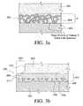
- FIG. 3 ais a partial detail sectional view illustrating the use of trabecular metal mechanical fixation means.
- FIG. 3 bis a partial detail sectional view illustrating the use of open cell foam metal mechanical fixation means.
- FIG. 4 ais a partial detail sectional view illustrating the use of perforated plate mechanical fixation means.
- FIG. 4 bis a partial detail sectional view illustrating the use of perforated peripheral flange mechanical fixation means.
- FIG. 4 cis a partial detail sectional view illustrating the use of perforated rib mechanical fixation means extending vertically into the elastomeric core.
- FIG. 4 dis a partial detail sectional view illustrating the use of wire mesh mechanical fixation means.
- FIG. 4 eis a partial detail sectional view illustrating the use of looped wire mechanical fixation means.
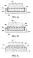
- FIG. 5 ais a partial detail sectional view of assembled intermediate perforated plate mechanical fixation means.
- FIG. 5 bis a partial detail sectional view of the embodiment of FIG. 5 a illustrated in an alternate embodiment with a harder elastomer secured to the intermediate perforated plate mechanical fixation means.
- FIG. 5 cis a partial detail sectional view showing a variation of the embodiment of FIG. 5 b , having a slidable dovetail engagement of the intermediate perforated plate to the rigid endplate.
- FIG. 6 ais a detail partial cross section of an alternate embodiment of this invention having additional compressive fixation applied to a peripheral extension of the flexible core.
- FIG. 6 bis a detail partial cross section showing a variation of the embodiment of FIG. 6 a , where compressive fixation is applied by a compression band.
- FIG. 6 cis a detail partial cross section showing another variation, where compressive fixation is applied by a ring compressed against the peripheral extension of the flexible core.
- FIG. 7 aillustrates an embodiment comprising an elastomeric joint prosthesis wherein the elastomeric member is attached to two hard, structural intramedullary members.
- FIG. 7 bis a sectional view of FIG. 13 a showing the attachment of the elastomeric member to the two hard, structural intramedullary members.
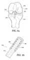
- FIG. 8 aillustrates an embodiment comprising an anterior cruciate replacement prosthesis in which the deformable elastomeric member is attached to two hard, bone fixation plugs.
- FIG. 8 bis a sectional view through bony fixation members of FIG. 8 a showing attachment of the deformable elastomeric member to the hard, bony fixation plugs.
- FIG. 9 aillustrates an embodiment comprising an intramedullary fixation rod having a central low stiffness region in which a deformable elastomer is attached to the two ends of the rod.
- FIG. 9 bis a sectional view through the central portion of the rod of FIG. 9 a showing attachment of deformable elastomer to the hard rod ends.
- the inventionprovides a method of attaching a member of flexible elastomeric material to a rigid structure in a medical implant so that the attachment of the elastomeric member is strong enough to withstand the loads of its intended application.
- the inventionachieves this goal by providing an article incorporating a porous structure, which may be rigid, the porous structure comprising open pores bounded by solid material and being spaced from a surface of a rigid substrate member to provide sufficient space between the porous structure and the surface for the elastomeric material to form a continuous body or bridge of elastomeric material between at least some of the elastomer-filled pores, whereby the elastomeric material cannot be mechanically detached from the implant without rupturing the body of elastomeric material.
- the porosity of the porous structureis greater than 21.5%, i.e., the projected area of the pores on the substrate surface underlying the porous structure constitutes more than 21.5% of the area of the underlying surface.
- the porous structureis spaced from the surface to provide a continuous uninterrupted layer or sheet of elastomer between the porous structure and the surface.
- the porous structurehave an interconnecting porosity greater than 21.5% by area, with porosity more typically running in the range of 30% to 80%.
- the elastomeris secured to a rigid metal support or plate by means of perforations in the support or plate which allow the elastomer, when molded onto the support, to penetrate through to the back side of the support and form a continuous body between at least some of the elastomer-filled perforations.
- the number and size of these perforations, and therefore their cross sectional area,can be varied to the match the respective strengths of the elastomer and the metal. For instance, if the strength of the metal is 10 times that of the elastomer and the perforations occupy 90% of the available cross sectional area, then the polymer within the perforations will have the same load bearing capacity as the remaining metal.
- Preferred devices prepared utilizing the present inventionachieve a strong fixation of an elastomeric member to a rigid substrate by incorporating:
- a two-dimensional or three-dimensional lattice structurepreferably having greater than 21.5% interconnecting porosity, so that the amount of elastomer within the lattice is greater than can be achieved using conventional beaded coatings and the like;
- a continuous bridge or layer of elastomeron the surface of the lattice furthest from the main body of the elastomeric member, whereby such a bridge or layer provides a strong bond between the portions of the elastomer within the lattice.
- a bridge or layer of elastomersupports the elastomer portions within the lattice and helps them to resist deformation under load, which could allow them to be pulled out of the lattice, with consequent failure of the attachment between elastomer and substrate and accompanying failure of the medical device.
- Such a bridge or layermay be formed by providing structure in the lattice around which the elastomer may loop, with consequent formation of a continuous band of elastomer connecting adjacent pores.
- a supporting layer of elastomermay be formed by providing an uninterrupted layer of elastomer on the surface of the porous structure that faces the substrate surface so that the elastomer material completely penetrates the porosity.
- Such a continuous layer of polymer, continuous with the polymer in the pores of the porous structure,provides a bond that helps to prevent the elastomer from being pulled out of the lattice.
- the rigid fixationmay utilize a two-dimensional lattice structure such as a perforated plate, perforated fin, wire mesh, or looped wire, or a three dimensional lattice structure such as open cell foam, trabecular metal porous surface or other high porosity structure having at least a major portion that is embedded in the elastomer.
- a two-dimensional lattice structuresuch as a perforated plate, perforated fin, wire mesh, or looped wire
- a three dimensional lattice structuresuch as open cell foam, trabecular metal porous surface or other high porosity structure having at least a major portion that is embedded in the elastomer.
- Such lattice structuresare preferably constructed to exhibit a net captive porosity greater than 21.5% (calculated as the total projected area of elastomer traversing through the pores or openings formed by the preferably rigid fixation structure divided by the combined projected area of rigid structure and elastomer). From one point of view, the elastomer material impregnating the pores or openings of the rigid lattice structure connects back to the main elastomer body in a continuous loop or the like. From another point of view, the elastomer impregnating the pores connects the main elastomer body to a continuous elastomer layer covering the opposite side of the rigid lattice structure. Such a configuration of lattice and elastomer produces a secure and stable assembly of elastomer and rigid lattice structure.
- Another preferred article of the inventionis an intervertebral disc prosthesis incorporating an elastomeric disc core secured to rigid endplates, wherein the flexible elastomer is molded onto a rigid (metal, polymer, composite, or ceramic) perforated plate member, and where the elastomer extends from one side of the plate member, though the perforations and reconnects to itself.
- the size, shape and location of these perforationscan be controlled to obtain a desired fixation strength.
- the net captive porositymay be calculated for certain geometries. For example, a square plate region of unit side length L with a single central circular hole of diameter 0.95 L therein will exhibit a net captive porosity of about 71%.
- the net captive porositywill be about 90%.
- the minimum cross section of the metal surrounding the holewill be the same, i.e., 0.025 L.
- the net captive porositywould be less than 21.5%.
- the number, location and size of the perforations in a perforated platecan be modified depending on the elastomer and the load conditions.
- the holesare preferably made to have smooth edges to avoid cutting action on the polymer connections during repetitive tensile and compressive loading.
- the thickness of a continuous layer of elastomer on the side of the perforated rigid plate opposite the main body of the elastomeric membercan be modified according to the tensile strength of elastomeric material.
- an intervertebral disc prosthesisusing an elastomeric disc core
- typical loading conditionsresult in the highest tensile stress developing at the outermost regions (the anterior and posterior regions) of the elastomeric core during flexion and extension.
- the stiffness differential between the rigid and flexible materialsintroduces an additional stress concentration factor.
- the stress tending to pull the rigid endplate from the elastomeric core in the highly stressed peripheral regionsmay be reduced by extending the elastomeric core peripherally beyond the edge of the rigid endplate and crimping the extended portion to the peripheral edge region of the rigid endplate.
- This compressive preload of the free extension of the elastomercounteracts the tensile loads and helps to shield the outermost portion of the elastomeric core from the tensile disassociative stresses. Such crimping would have little or no contribution to the flexural stiffness of the disc but would provide for a significantly stronger fixation at these highly stressed regions.
- FIG. 1illustrates schematically an intervertebral disc prosthesis 10 implanted between adjacent upper and lower vertebrae 11 and 12 in a human spinal motion segment.
- FIG. 2is a more detailed cross-sectional view of the disc prosthesis 10 , showing a first or upper rigid plate 310 , a second or lower rigid plate 320 , and a flexible elastomeric core 330 interposed between and fixedly assembled to the two rigid plates by rigid fixation means 311 and 321 .
- the upper and lower rigid plates 310 and 320are generally similar to each other, and the disc prosthesis 10 is symmetrically placed about a midline vertical plane.
- Rigid plates 310 and 320are intended for fixation to the vertebral bones 301 and 302 by various generally conventional fixation means 340 and 341 (e.g., porous surface coating).
- Rigid plates 310 and 320are made of biocompatible material, and preferably a metal such as Ti6Al4V (Ti-6% Al-4% V). Common metal fabrication methods may be used to fabricate rigid plates 310 and 320 .
- FIG. 3 ais a detail view of a rigid fixation means suitable for use in the embodiment of FIG. 2 , illustrating a preferred configuration of the fixation means wherein a trabecular metal porous structure 402 is used to produce porosity larger than 21.5% (projected area basis).
- the porous structure 402is attached to endplate 320 by conventional means and provides for elastomer 330 to extend through high net captive porosity 404 from the flexible core region 330 to impregnate the porous structure 402 and interconnect with itself therein, thereby forming an integral connection back to core region 330 , the porous structure 402 thus being embedded in the elastomer.
- the ratio of elastomer to metalcould conveniently be about 80% (projected area basis) to provide a satisfactory bond between the core region 330 and the rigid substrate plate 320 .
- FIG. 3 billustrates an alternate embodiment of the prosthesis of FIG. 3 a , wherein the elastomeric core 400 is comprised of soft elastomeric material 405 and a harder elastomeric material 406 forming a transition plate 407 .
- Transition plate 407is fixed to the rigid substrate plate 320 by impregnation of a porous structure 408 , e.g., an open cell porous structure as illustrated, to provide mechanical fixation.
- a porous structure 408e.g., an open cell porous structure as illustrated, to provide mechanical fixation.
- Such porous cell structuresmay be formed by conventional procedures, e.g., such as used to form patterned substrate surfaces by chemical or electrochemical etching, optionally using patterned photoresist layers, and the like.
- the elastomeric material 406occupies the spaces within the porous structure 408 and, because of the porosity 410 , forms a mechanical connection.
- This embodimentis additionally provided with a flange 411 that extends laterally beyond the vertical wall 412 of the elastomeric core 405 .
- porous structure 408may be extended laterally a distance 413 for additional mechanical fixation. Because an intervertebral prosthesis experiences maximum stresses at the outer rim of the vertical wall 412 during bending of the vertebral column, flange 411 may be provided to further disperse these loads over a wider area, and minimizes stress concentration developed due to the different stiffness between elastomer 406 and rigid porous structure 408 .
- Such a flange and porous structure extensionmay be used with all embodiments of the invention disclosed herein and will not be separately discussed in connection with other embodiments.
- FIG. 4 aillustrates an alternate embodiment wherein secure and stable fixation is achieved by the use of elastomer 510 extending though perforations 511 in a rigid structure (e.g., a plate) 512 attached to rigid substrate (e.g., metal endplate of an intervertebral prosthesis) 513 .
- Elastomer materialextends through perforated holes 511 from the main elastomer core 510 and forms a substantially continuous elastomeric layer or sheet 514 on the opposite side of rigid structure 512 .
- Rigid structure 512 and perforations 511may be in the form of a perforated plate as illustrated in FIG. 4 a , or other similarly constructed structures having other opening geometries and orientations.
- FIG. 4 billustrates in detailed section an additional alternate embodiment having a horizontal peripheral flange 515 constituting the rigid fixation means and having a series of perforations 516 .
- Elastomer 510extends though perforations 516 and is connected back to the main polymer core on the opposite side of the flange as indicated generally at 514 .
- FIG. 4 cillustrates another embodiment having one or more flanges or ribs 520 extending generally vertically from the surface of a substrate, protruding into the flexible elastomeric core 510 , and having perforations 521 extending generally laterally through flanges 520 .
- elastomer materialextends through the perforations 521 , whereby the elastomer material forms a substantially continuous body with the elastomer material 522 along the sides of the flange 520 .
- FIG. 4 dillustrates an alternate embodiment wherein a wire mesh 530 is affixed to the rigid substrate 532 , and spaced from the surface thereof by attachment to a generally vertical peripheral rim at 531 .
- Elastomer 510extends from the first side 533 of wire mesh 530 though the captive porosity of the mesh and forms a continuous layer or sheet 534 of elastomer on the opposing side of wire mesh 530 .
- a wire structuremay be formed as illustrated in FIG. 4 e by attachments 541 of a structure containing upstanding wire loops 540 to the surface of the substrate 542 .
- elastomer 510extends from a region 545 and first side 543 of wire loops 540 though the captive porosity, as indicated at 544 , and back to itself, thereby forming a continuous body of elastomer through the wire loops 540 .
- the embodiment of FIG. 4 emay also be provided with additional fixation strength by employing an elastomeric core with a harder transition plate and/or with a laterally extending flange as shown in the embodiment of FIG. 3 b.
- An elastomeric membere.g., an elastomeric core of an intervertebral prosthesis
- a rigid substratee.g., a metal endplate of such a prosthesis
- interfitting or mating structuresConventional methods for assembling such modular structures include press fits, grooves, and interference locking or dovetail fixation mechanisms formed in the elastomer.
- interfitting or mating structuresmay present problems because the elastomer component may deform and disengage when the assembly is subjected to forces tending to separate the components.
- the method and devices of the inventionpermit the construction of modular components that can be readily assembled, yet resist disengagement of the elastomer component.
- Such devicesmay use an intermediate (and preferably rigid) anchoring structure 605 as illustrated in the embodiments of FIGS. 5 a and 5 b .
- the anchoring structure 605is constituted by a dependent peripheral flange of a perforated plate 609 .
- a rigid plate 600is provided with peripheral mechanical means of fixation 602 , illustrated by groove 603 that engages a protrusion 604 of intermediate anchoring structure 605 , thereby forming a secure connection between the two rigid structures, i.e., rigid (e.g., metal) anchoring structure 605 and rigid (e.g., metal) substrate 600 .
- the intermediate anchoring structure 605may be unitary with the porous attachment structure (e.g., plate 609 ), as shown, or the porous attachment structure and anchoring structure may be formed as discrete components that are attached to each other.
- Elastomer core 510is securely fixed to intermediate anchoring structure 605 by porous structures such as those described above and exemplified here by metal plate 609 .
- the elastomeric core 510is secured to the intermediate anchoring structure 605 , which is in turn fixed to rigid endplate 600 . It will be appreciated that this embodiment is useful for reduction of manufacturing inventory where the product family may require large numbers of varied polymer and rigid plate configurations. Thus, an assembly with the same polymer and intermediate anchoring means may be independently assembled to rigid endplates of several different sizes and designs.
- FIG. 5 billustrates an embodiment wherein elastomer core 510 is bonded to a harder elastomer 608 , which is secured (via plate 609 ) to the intermediate anchoring structure 605 , which is in turn assembled to rigid endplate 600 .
- Rigid endplate 600has mechanical means of fixation 602 illustrated by a recess or groove 603 cooperating with a projection 604 of anchoring structure 605 , thereby forming a secure connection with plate 600 .
- FIG. 5 cillustrates an additional embodiment similar to that illustrated in FIG. 5 b .
- the hard elastomer 608is fixed to a typically metallic porous plate 710 , which incorporates a male dovetail 711 securely engaging a female dovetail 731 formed on rigid endplate 600 .
- the porous attachment structureis provided on the substrate member so as to cover a portion thereof, while the elastomeric material fills a major portion (>50%) of a volume adjacent to the covered portion of the substrate and containing the porous attachment structure.
- the elastomeric materialis thereby firmly secured to the substrate.
- the entire volume between the porous attachment structure and the facing surface portion of the substratemay advantageously be filled with elastomer (as, for example, in FIGS. 4 a , 4 b , and 4 d ).
- FIGS. 6 a - 6 cillustrate, in detail, a partial cross section of other embodiments of the invention having a rigid fixation structure 905 , as discussed above, and additionally incorporating structure to compress a laterally extended elastomer flange against a rigid fixation structure for the elastomer or against a rigid substrate.
- a lateral extension of the elastomer core 902is preferably fashioned as a flange 900 extending outwardly from the core 902 .
- the flange having original form indicated in phantom at 903is compressed by a compressive element 901 having an original form indicated in phantom at 904 .
- the deformed compressive element 901is preferably integral to the rigid fixation means 906 , as shown, but may be alternatively assembled to the prosthesis, after assembly of the elastomeric core and rigid endplate, in order to provide the desired compression.
- Flexible core 902 and flange element 903are preformed, and subsequently compression element 904 is permanently deformed to the shape indicated at 901 , thereby engaging and deforming flange element 903 to the compressed form 900 .
- the compressive element 906may be in the form of a peripheral band achieving compression by interference fit over the flexible core flange 901 .
- Alternate embodimentsmay utilize screws, wires, clips, or other conventional fixation means in conjunction with a peripheral flange to provide the compressive force required to compress the flexible core flange.
- FIG. 6 billustrates in detail, a partial cross section of an alternate embodiment of FIG. 6 a , wherein a compression band 920 is assembled over flange 921 having an original form 922 and compresses flange 921 into groove 923 to a deformed shape 924 .
- FIG. 6 cillustrates, in detail, a partial cross section of an alternate embodiment of FIG. 6 a , wherein the compressive fixation is achieved by the forcible assembly of compression element 931 , extending peripherally, between flange element 932 and an exterior peripheral retaining groove 933 , whereby flange 932 is compressed against interior retaining groove 934 on rigid substrate 910 .
- FIGS. 7 and 7 billustrate an elastomeric joint prosthesis 550 according to the invention, suitable, e.g., as a prosthetic replacement for a finger joint.
- the prosthesiscomprises a flexible elastomeric body 552 fastened to rigid intramedullary members 554 , made of metal, rigid plastic, or the like, and inserted, by conventional procedures, into phalanges 556 .
- the intramedullary members 554are provided with recessed regions 558 at the appropriate ends thereof.
- Rigid perforated plates 560made of metal, or the like (shown in phantom in FIG.
- the flexible elastomeric body 552is molded or otherwise attached to the intramedullary members 554 so that the elastomeric material extends through each perforated plate 556 and forms a continuous layer of polymer material behind the plate 560 (best seen in the partial sectional detail, FIG. 7 b ).
- FIGS. 8 a and 8 billustrate a further prosthesis 570 according to the invention, suitable, e.g., as a prosthetic replacement for an anterior cruciate ligament of a knee joint or other ligament, a tendon or the like.
- FIG. 8 ashows the ligament prosthesis 570 , in partial phantom, implanted between the femur 572 and the tibia 574 of a knee joint.
- the prosthesis 570comprises an elongated body 576 , ends of which are provided with hard, rigid bone fixation plugs 578 , which may be constructed of conventional materials and implanted by conventional techniques. As shown, and best seen in the partial sectional detail FIG.
- each of the bone fixation plugs 578is preferably tubular, with perforated plates, or the like, 580 lying in respective planes substantially parallel to the plug axis and extending transversely across the lumen of the tubular plugs 578 .
- the elastomeric body 576is molded or otherwise attached to the bone fixation plug 578 so that the elastomeric material extends through each perforated plate 580 and forms a continuous layer of polymer material behind the plate 580 .
- FIGS. 9 a and 9 billustrate an embodiment comprising an intramedullar fixation rod 650 for a long bone such as a femur, wherein the rod has a central low stiffness region 652 in which a deformable elastomer is interposed between two intramedullar portions 654 of the rod.
- FIG. 9 bis a sectional view through the central region 652 of fixation rod 650 of FIG. 9 a showing a segment of deformable elastomer 656 attached to the internal ends 658 of the intramedullar portions 654 of the fixation rod 650 .
- the elastomer of the elastomer segment 656is molded or otherwise attached to rigid perforated projections 660 (shown in phantom) extending from the internal ends 658 of the intramedullar portions 654 , and extends through the perforations of the rigid projections 660 to form a unitary body holding together the intramedullary portions 654 .
- This exampleillustrates the additional strength and uniformity obtainable using an embodiment of the invention as compared with known fixation of elastomer to a rigid substrate having a layer of beads.
- Test sampleswere prepared by attaching a cylindrical elastomeric core of 11.2 mm diameter and 4 mm length to two titanium alloy endplates such that the whole assembly could be tested in tension to failure.
- the elastomer usedwas 75 D durometer polycarbonate-polyurethane (Chronoflex-C, CardioTech Inc., Wilmington, Mass.), which was attached to the metal endplates, made of Ti-6% Al-4% V surgical alloy, through injection molding.
- the experimentexamined different attachment means including a porous coating and a perforated plate configuration.
- the inventiongenerally provides for secure attachment of an elastomer to a rigid substrate.
- the inventionprovides increased fixation strength of a flexible elastomeric member to a rigid implant substrate member, such as an elastomeric core fixed to an endplate of a spinal disc prosthesis, without relying solely upon either a porous coating or an adhesive layer for attachment.
- the inventionadditionally provides a means of fixing elastomeric members to rigid members in a manner that allows for simpler manufacturing and for easier inspection of final product.
Landscapes
- Health & Medical Sciences (AREA)
- Orthopedic Medicine & Surgery (AREA)
- Engineering & Computer Science (AREA)
- Biomedical Technology (AREA)
- Life Sciences & Earth Sciences (AREA)
- Veterinary Medicine (AREA)
- Public Health (AREA)
- General Health & Medical Sciences (AREA)
- Heart & Thoracic Surgery (AREA)
- Animal Behavior & Ethology (AREA)
- Neurology (AREA)
- Oral & Maxillofacial Surgery (AREA)
- Vascular Medicine (AREA)
- Transplantation (AREA)
- Cardiology (AREA)
- Surgery (AREA)
- Rheumatology (AREA)
- Rehabilitation Therapy (AREA)
- Nuclear Medicine, Radiotherapy & Molecular Imaging (AREA)
- Medical Informatics (AREA)
- Molecular Biology (AREA)
- Prostheses (AREA)
- Materials For Medical Uses (AREA)
Abstract
Description
- A. Porous surface using a double layer of sintered beads of −45+60 diameter to provide a porosity of approximately 21%
- B. Perforated surface with a regular array of 1.5 mm through-holes to provide a porosity of approximately 44%. The design provided for the elastomer to extend through the holes and to provide for a full sheet of 1 mm thick polymer on the far side
| TABLE 1 | ||
| Attachment | Maximum | |
| Sample | Means | Force (N) |
| A | −45 + 60 | 493 ± 42 |
| Double Layer | ||
| of Beads | ||
| B | Perforated | 811 ± 50 |
| Plate | ||
Claims (19)
Priority Applications (1)
| Application Number | Priority Date | Filing Date | Title |
|---|---|---|---|
| US11/814,369US8864831B2 (en) | 2005-01-19 | 2006-01-19 | Fixation of elastomer to rigid structures |
Applications Claiming Priority (4)
| Application Number | Priority Date | Filing Date | Title |
|---|---|---|---|
| US64452705P | 2005-01-19 | 2005-01-19 | |
| US69343005P | 2005-06-24 | 2005-06-24 | |
| PCT/US2006/001629WO2006078662A1 (en) | 2005-01-19 | 2006-01-19 | Fixation of elastomer to rigid structures |
| US11/814,369US8864831B2 (en) | 2005-01-19 | 2006-01-19 | Fixation of elastomer to rigid structures |
Publications (2)
| Publication Number | Publication Date |
|---|---|
| US20080306609A1 US20080306609A1 (en) | 2008-12-11 |
| US8864831B2true US8864831B2 (en) | 2014-10-21 |
Family
ID=43927674
Family Applications (1)
| Application Number | Title | Priority Date | Filing Date |
|---|---|---|---|
| US11/814,369Active2030-04-16US8864831B2 (en) | 2005-01-19 | 2006-01-19 | Fixation of elastomer to rigid structures |
Country Status (11)
| Country | Link |
|---|---|
| US (1) | US8864831B2 (en) |
| EP (1) | EP1838249B1 (en) |
| JP (1) | JP5028276B2 (en) |
| KR (1) | KR20070118593A (en) |
| CN (1) | CN101137340B (en) |
| AT (1) | ATE548992T1 (en) |
| AU (1) | AU2006206559A1 (en) |
| BR (1) | BRPI0606423A2 (en) |
| CA (1) | CA2595258A1 (en) |
| ES (1) | ES2387194T3 (en) |
| WO (1) | WO2006078662A1 (en) |
Cited By (19)
| Publication number | Priority date | Publication date | Assignee | Title |
|---|---|---|---|---|
| US10182923B2 (en) | 2015-01-14 | 2019-01-22 | Stryker European Holdings I, Llc | Spinal implant with porous and solid surfaces |
| US10226883B2 (en) | 2014-06-26 | 2019-03-12 | Vertera, Inc. | Mold and process for producing porous devices |
| US10271959B2 (en) | 2009-02-11 | 2019-04-30 | Howmedica Osteonics Corp. | Intervertebral implant with integrated fixation |
| US10405962B2 (en) | 2014-06-26 | 2019-09-10 | Vertera, Inc. | Porous devices and methods of producing the same |
| US10537666B2 (en) | 2015-05-18 | 2020-01-21 | Stryker European Holdings I, Llc | Partially resorbable implants and methods |
| US10603182B2 (en) | 2015-01-14 | 2020-03-31 | Stryker European Holdings I, Llc | Spinal implant with fluid delivery capabilities |
| US10835388B2 (en) | 2017-09-20 | 2020-11-17 | Stryker European Operations Holdings Llc | Spinal implants |
| US11160668B2 (en) | 2017-03-13 | 2021-11-02 | Institute for Musculoskeletal Science and Education, Ltd. | Implant with bone contacting elements having helical and undulating planar geometries |
| US11213405B2 (en) | 2017-03-13 | 2022-01-04 | Institute for Musculoskeletal Science and Education, Ltd. | Implant with structural members arranged around a ring |
| USD944990S1 (en) | 2015-06-23 | 2022-03-01 | Vertera, Inc. | Cervical interbody fusion device |
| US11452611B2 (en) | 2016-10-25 | 2022-09-27 | Institute for Musculoskeletal Science and Education, Ltd. | Implant with protected fusion zones |
| US11780175B2 (en) | 2012-08-21 | 2023-10-10 | Nuvasive, Inc. | Systems and methods for making porous films, fibers, spheres, and other articles |
| US11793652B2 (en) | 2017-11-21 | 2023-10-24 | Institute for Musculoskeletal Science and Education, Ltd. | Implant with improved bone contact |
| US11819419B2 (en) | 2015-04-29 | 2023-11-21 | Institute for Musculoskeletal Science and Education, Ltd. | Implant with curved bone contacting elements |
| US11826261B2 (en) | 2015-04-29 | 2023-11-28 | Institute for Musculoskeletal Science and Education, Ltd. | Coiled implants and systems and methods of use thereof |
| US11951018B2 (en) | 2017-11-21 | 2024-04-09 | Institute for Musculoskeletal Science and Education, Ltd. | Implant with improved flow characteristics |
| US12097123B2 (en) | 2015-04-29 | 2024-09-24 | Institute for Musculoskeletal Science and Education, Ltd. | Implant with arched bone contacting elements |
| TWI861203B (en)* | 2019-09-04 | 2024-11-11 | 德商貝拉塞諾有限公司 | Implants and method for forming an implant |
| US12208011B2 (en) | 2016-10-25 | 2025-01-28 | Institute for Musculoskeletal Science and Education, Ltd. | Implant with multi-layer bone interfacing lattice |
Families Citing this family (42)
| Publication number | Priority date | Publication date | Assignee | Title |
|---|---|---|---|---|
| US20070055373A1 (en) | 2005-09-08 | 2007-03-08 | Zimmer Spine, Inc. | Facet replacement/spacing and flexible spinal stabilization |
| DE102006016986A1 (en)* | 2006-04-06 | 2007-10-18 | Aesculap Ag & Co. Kg | Intervertebral implant |
| US8092533B2 (en)* | 2006-10-03 | 2012-01-10 | Warsaw Orthopedic, Inc. | Dynamic devices and methods for stabilizing vertebral members |
| US7887592B2 (en)* | 2007-02-14 | 2011-02-15 | Spinal Kinetics, Inc. | Prosthetic intervertebral discs assemblies having compressible core elements with enhanced torque transmission |
| DE202008001079U1 (en) | 2008-01-25 | 2008-03-27 | Aesculap Ag & Co. Kg | Intervertebral implant |
| US8470045B2 (en) | 2008-05-05 | 2013-06-25 | K2M, Inc. | Endplate for an intervertebral prosthesis and prosthesis incorporating the same |
| JP2012500058A (en)* | 2008-08-13 | 2012-01-05 | スメド−ティーエイ/ティーディー・エルエルシー | Orthopedic implant with a porous structural member |
| US10842645B2 (en) | 2008-08-13 | 2020-11-24 | Smed-Ta/Td, Llc | Orthopaedic implant with porous structural member |
| US9616205B2 (en) | 2008-08-13 | 2017-04-11 | Smed-Ta/Td, Llc | Drug delivery implants |
| US9700431B2 (en) | 2008-08-13 | 2017-07-11 | Smed-Ta/Td, Llc | Orthopaedic implant with porous structural member |
| US20100042213A1 (en) | 2008-08-13 | 2010-02-18 | Nebosky Paul S | Drug delivery implants |
| US20100042226A1 (en)* | 2008-08-13 | 2010-02-18 | Nebosky Paul S | Orthopaedic implant with spatially varying porosity |
| WO2010025386A1 (en) | 2008-08-29 | 2010-03-04 | Smed-Ta/Td, Llc | Orthopaedic implant |
| CN102281829A (en)* | 2008-11-19 | 2011-12-14 | 安杜奥斯皮迪克公司 | Intramedullary repair system for bone fractures |
| WO2010059860A1 (en) | 2008-11-19 | 2010-05-27 | Endoorthopaedics, Inc. | Intramedullary repair system for bone fractures |
| FI20095084A0 (en) | 2009-01-30 | 2009-01-30 | Pekka Vallittu | Composite and its use |
| WO2010088766A1 (en)* | 2009-02-03 | 2010-08-12 | National Research Council Of Canada | Implant for total disc replacement, and method of forming |
| US9549820B2 (en)* | 2009-06-25 | 2017-01-24 | Zimmer, Inc. | Glenoid implant with synthetic labrum |
| WO2011037668A1 (en)* | 2009-09-23 | 2011-03-31 | Zimmer Spine, Inc. | Composite implant |
| IT1398443B1 (en)* | 2010-02-26 | 2013-02-22 | Lima Lto S P A Ora Limacorporate Spa | INTEGRATED PROSTHETIC ELEMENT |
| US8685101B2 (en) | 2011-10-10 | 2014-04-01 | DePuy Synthes Products, LLC | Implant with compliant layer |
| EP2922504A1 (en)* | 2012-11-21 | 2015-09-30 | K2M, Inc. | Flanged endplate for an intervertebral disc prosthesis and intervertebral disc prosthesis incorporating same |
| US9693874B2 (en)* | 2013-03-15 | 2017-07-04 | Blackstone Medical, Inc. | Composite spinal interbody device and method |
| KR102448693B1 (en)* | 2014-09-19 | 2022-09-30 | 삼성전자주식회사 | Force transmission frame and exercise assisting device including same |
| RU2017125255A (en)* | 2014-12-16 | 2019-01-18 | Керамтек Гмбх | INTERDERVERSE CAGES AND INSTALLATION INSTRUMENTS |
| DE202015005873U1 (en)* | 2015-08-25 | 2016-11-28 | Rti Sports Gmbh | bicycle saddle |
| US20200000595A1 (en) | 2016-06-07 | 2020-01-02 | HD LifeSciences LLC | High X-Ray Lucency Lattice Structures |
| US9962269B2 (en)* | 2016-06-07 | 2018-05-08 | HD LifeSciences LLC | Implant with independent endplates |
| CN106943214A (en)* | 2016-11-30 | 2017-07-14 | 重庆润泽医药有限公司 | A kind of light-duty Invasive lumbar fusion device |
| US10195035B1 (en) | 2016-12-30 | 2019-02-05 | Newtonoid Technologies, L.L.C. | Responsive biomechanical implants and devices |
| CA3061043A1 (en) | 2017-02-14 | 2018-08-23 | HD LifeSciences LLC | High x-ray lucency lattice structures and variably x-ray lucent markers |
| EP3606473A4 (en) | 2017-04-01 | 2020-12-30 | HD Lifesciences LLC | FLUID INTERFACE SYSTEM FOR IMPLANTS |
| CA3058365A1 (en) | 2017-04-01 | 2018-10-04 | HD LifeSciences LLC | Three-dimensional lattice structures for implants |
| HK1246069A2 (en)* | 2017-12-01 | 2018-08-31 | 香港科能有限公司 | Artificial bone |
| EP3826582A4 (en) | 2018-07-26 | 2022-05-25 | Nanohive Medical LLC | DYNAMIC IMPLANT FIXATION PLATE |
| US11497617B2 (en) | 2019-01-16 | 2022-11-15 | Nanohive Medical Llc | Variable depth implants |
| US11857393B2 (en)* | 2019-03-19 | 2024-01-02 | Alm Ortho, Inc. | Internal bone fixation device |
| IT201900003947A1 (en)* | 2019-03-19 | 2020-09-19 | Mt Ortho S R L | Granule in biocompatible metal material for vertebroplasty. |
| CN111281611B (en)* | 2019-12-30 | 2022-05-24 | 雅博尼西医疗科技(苏州)有限公司 | Method for connecting porous structure and substrate |
| TWI724962B (en) | 2020-08-13 | 2021-04-11 | 可成生物科技股份有限公司 | Artificial intervertebral disc |
| CN111973321A (en)* | 2020-08-13 | 2020-11-24 | 广州市万和整形材料有限公司 | Chin implant with split embedded structure |
| CN117863156B (en)* | 2024-02-28 | 2025-10-03 | 华中科技大学 | A flexible body interconnection structure based on porous structure and forming method |
Citations (94)
| Publication number | Priority date | Publication date | Assignee | Title |
|---|---|---|---|---|
| US3867728A (en) | 1971-12-30 | 1975-02-25 | Cutter Lab | Prosthesis for spinal repair |
| US3875595A (en) | 1974-04-15 | 1975-04-08 | Edward C Froning | Intervertebral disc prosthesis and instruments for locating same |
| US4349921A (en) | 1980-06-13 | 1982-09-21 | Kuntz J David | Intervertebral disc prosthesis |
| US4759766A (en) | 1984-09-04 | 1988-07-26 | Humboldt-Universitaet Zu Berlin | Intervertebral disc endoprosthesis |
| US4759769A (en) | 1987-02-12 | 1988-07-26 | Health & Research Services Inc. | Artificial spinal disc |
| US4772287A (en) | 1987-08-20 | 1988-09-20 | Cedar Surgical, Inc. | Prosthetic disc and method of implanting |
| WO1989003663A1 (en) | 1987-10-29 | 1989-05-05 | Atos Medical Ab | Joint prosthesis |
| US4863477A (en) | 1987-05-12 | 1989-09-05 | Monson Gary L | Synthetic intervertebral disc prosthesis |
| US4911718A (en) | 1988-06-10 | 1990-03-27 | University Of Medicine & Dentistry Of N.J. | Functional and biocompatible intervertebral disc spacer |
| US4932969A (en) | 1987-01-08 | 1990-06-12 | Sulzer Brothers Limited | Joint endoprosthesis |
| US4946378A (en) | 1987-11-24 | 1990-08-07 | Asahi Kogaku Kogyo Kabushiki Kaisha | Artificial intervertebral disc |
| WO1990011740A1 (en) | 1989-04-08 | 1990-10-18 | Robert Bosch Gmbh | Artificial spinal disc |
| US5047055A (en) | 1990-12-21 | 1991-09-10 | Pfizer Hospital Products Group, Inc. | Hydrogel intervertebral disc nucleus |
| US5071437A (en) | 1989-02-15 | 1991-12-10 | Acromed Corporation | Artificial disc |
| US5123926A (en) | 1991-02-22 | 1992-06-23 | Madhavan Pisharodi | Artificial spinal prosthesis |
| US5171281A (en) | 1988-08-18 | 1992-12-15 | University Of Medicine & Dentistry Of New Jersey | Functional and biocompatible intervertebral disc spacer containing elastomeric material of varying hardness |
| US5192326A (en) | 1990-12-21 | 1993-03-09 | Pfizer Hospital Products Group, Inc. | Hydrogel bead intervertebral disc nucleus |
| EP0566810A1 (en) | 1992-04-21 | 1993-10-27 | SULZER Medizinaltechnik AG | Artificial spinal disc |
| US5258031A (en) | 1992-01-06 | 1993-11-02 | Danek Medical | Intervertebral disk arthroplasty |
| US5306309A (en) | 1992-05-04 | 1994-04-26 | Calcitek, Inc. | Spinal disk implant and implantation kit |
| US5306308A (en) | 1989-10-23 | 1994-04-26 | Ulrich Gross | Intervertebral implant |
| US5314478A (en) | 1991-03-29 | 1994-05-24 | Kyocera Corporation | Artificial bone connection prosthesis |
| US5314477A (en) | 1990-03-07 | 1994-05-24 | J.B.S. Limited Company | Prosthesis for intervertebral discs and instruments for implanting it |
| US5320644A (en) | 1991-08-30 | 1994-06-14 | Sulzer Brothers Limited | Intervertebral disk prosthesis |
| JPH06285099A (en) | 1993-02-09 | 1994-10-11 | Acromed Corp | Spinal intervertebral disk prosthesis for exchanging injured spinal intervertebral disk |
| EP0642775A1 (en) | 1993-09-14 | 1995-03-15 | Commissariat A L'energie Atomique | Intervertebral disc prosthesis |
| US5401269A (en) | 1992-03-13 | 1995-03-28 | Waldemar Link Gmbh & Co. | Intervertebral disc endoprosthesis |
| WO1995019153A1 (en) | 1994-01-18 | 1995-07-20 | Beer John C | Synthetic intervertebral disc |
| US5514180A (en) | 1994-01-14 | 1996-05-07 | Heggeness; Michael H. | Prosthetic intervertebral devices |
| US5534028A (en) | 1993-04-20 | 1996-07-09 | Howmedica, Inc. | Hydrogel intervertebral disc nucleus with diminished lateral bulging |
| US5545229A (en) | 1988-08-18 | 1996-08-13 | University Of Medicine And Dentistry Of Nj | Functional and biocompatible intervertebral disc spacer containing elastomeric material of varying hardness |
| US5556431A (en) | 1992-03-13 | 1996-09-17 | B+E,Uml U+Ee Ttner-Janz; Karin | Intervertebral disc endoprosthesis |
| US5562738A (en) | 1992-01-06 | 1996-10-08 | Danek Medical, Inc. | Intervertebral disk arthroplasty device |
| US5674296A (en) | 1994-11-14 | 1997-10-07 | Spinal Dynamics Corporation | Human spinal disc prosthesis |
| US5676702A (en) | 1994-12-16 | 1997-10-14 | Tornier S.A. | Elastic disc prosthesis |
| US5683465A (en) | 1996-03-18 | 1997-11-04 | Shinn; Gary Lee | Artificial intervertebral disk prosthesis |
| US5824093A (en) | 1994-10-17 | 1998-10-20 | Raymedica, Inc. | Prosthetic spinal disc nucleus |
| US5824094A (en) | 1997-10-17 | 1998-10-20 | Acromed Corporation | Spinal disc |
| US5888226A (en) | 1997-11-12 | 1999-03-30 | Rogozinski; Chaim | Intervertebral prosthetic disc |
| US5893889A (en) | 1997-06-20 | 1999-04-13 | Harrington; Michael | Artificial disc |
| WO1999022675A1 (en) | 1997-10-31 | 1999-05-14 | Depuy Acromed, Inc. | Spinal disc prosthesis |
| US5958314A (en)* | 1994-02-04 | 1999-09-28 | Draenert; Klaus | Process for the preparation of porous material |
| US5976186A (en) | 1994-09-08 | 1999-11-02 | Stryker Technologies Corporation | Hydrogel intervertebral disc nucleus |
| FR2784291A1 (en) | 1998-10-09 | 2000-04-14 | Dimso Sa | Intervertebral disc prosthesis has connecting pieces with through cells between plates and core |
| US6110210A (en)* | 1999-04-08 | 2000-08-29 | Raymedica, Inc. | Prosthetic spinal disc nucleus having selectively coupled bodies |
| US6113637A (en) | 1998-10-22 | 2000-09-05 | Sofamor Danek Holdings, Inc. | Artificial intervertebral joint permitting translational and rotational motion |
| US6113640A (en)* | 1997-06-11 | 2000-09-05 | Bionx Implants Oy | Reconstructive bioabsorbable joint prosthesis |
| US6136031A (en) | 1998-06-17 | 2000-10-24 | Surgical Dynamics, Inc. | Artificial intervertebral disc |
| US6162252A (en)* | 1997-12-12 | 2000-12-19 | Depuy Acromed, Inc. | Artificial spinal disc |
| US6187043B1 (en) | 1987-12-22 | 2001-02-13 | Walter J. Ledergerber | Implantable prosthetic device |
| US6187048B1 (en) | 1994-05-24 | 2001-02-13 | Surgical Dynamics, Inc. | Intervertebral disc implant |
| US6224607B1 (en) | 1999-01-25 | 2001-05-01 | Gary K. Michelson | Instrumentation and method for creating an intervertebral space for receiving an implant |
| US20010016773A1 (en) | 1998-10-15 | 2001-08-23 | Hassan Serhan | Spinal disc |
| US6296664B1 (en) | 1998-06-17 | 2001-10-02 | Surgical Dynamics, Inc. | Artificial intervertebral disc |
| US20010032017A1 (en) | 1999-12-30 | 2001-10-18 | Alfaro Arthur A. | Intervertebral implants |
| US6368350B1 (en) | 1999-03-11 | 2002-04-09 | Sulzer Spine-Tech Inc. | Intervertebral disc prosthesis and method |
| US6395032B1 (en) | 1998-12-11 | 2002-05-28 | Dimso (Distribution Medicale Du Sud-Ouest) | Intervertebral disc prosthesis with liquid chamber |
| US20020077701A1 (en) | 2000-12-15 | 2002-06-20 | Kuslich Stephen D. | Annulus-reinforcing band |
| US6419706B1 (en) | 1997-12-19 | 2002-07-16 | Sofamor S.N.C. | Partial disc prosthesis |
| US6419704B1 (en) | 1999-10-08 | 2002-07-16 | Bret Ferree | Artificial intervertebral disc replacement methods and apparatus |
| US6482234B1 (en) | 2000-04-26 | 2002-11-19 | Pearl Technology Holdings, Llc | Prosthetic spinal disc |
| US6527804B1 (en) | 1998-12-11 | 2003-03-04 | Dimso (Distribution Medicale Du Sud-Quest) | Intervertebral disk prosthesis |
| US20030045939A1 (en) | 2001-08-24 | 2003-03-06 | Simon Casutt | Artificial intervertebral disc |
| US6548569B1 (en)* | 1999-03-25 | 2003-04-15 | Metabolix, Inc. | Medical devices and applications of polyhydroxyalkanoate polymers |
| US20030074066A1 (en) | 2001-07-16 | 2003-04-17 | Errico Joseph P. | Artificial intervertebral disc having limited rotation using a captured ball and socket joint with a solid ball, a retaining cap, and an interference pin |
| US6579320B1 (en) | 1998-12-11 | 2003-06-17 | Stryker Spine | Intervertebral disc prosthesis with contact blocks |
| US6579321B1 (en) | 1999-05-17 | 2003-06-17 | Vanderbilt University | Intervertebral disc replacement prosthesis |
| US6582468B1 (en) | 1998-12-11 | 2003-06-24 | Spryker Spine | Intervertebral disc prosthesis with compressible body |
| US6582466B1 (en) | 1998-12-11 | 2003-06-24 | Stryker Spine | Intervertebral disc prosthesis with reduced friction |
| US6582467B1 (en) | 2000-10-31 | 2003-06-24 | Vertelink Corporation | Expandable fusion cage |
| US6592624B1 (en) | 1999-11-24 | 2003-07-15 | Depuy Acromed, Inc. | Prosthetic implant element |
| US20030135277A1 (en) | 2001-11-26 | 2003-07-17 | Sdgi Holdings, Inc. | Implantable joint prosthesis and associated instrumentation |
| US6607558B2 (en) | 2001-07-03 | 2003-08-19 | Axiomed Spine Corporation | Artificial disc |
| US6626943B2 (en) | 2001-08-24 | 2003-09-30 | Sulzer Orthopedics Ltd. | Artificial intervertebral disc |
| WO2003090650A1 (en) | 2002-04-25 | 2003-11-06 | Blackstone Medical, Inc. | Artificial intervertebral disc |
| US6682562B2 (en) | 2000-03-10 | 2004-01-27 | Eurosurgical Sa | Intervertebral disc prosthesis |
| WO2004033516A1 (en) | 2002-10-08 | 2004-04-22 | Ranier Limited | High precision manufacture of polyurethane products such as spinal disc implants having gradual modulus variation |
| US6726720B2 (en) | 2002-03-27 | 2004-04-27 | Depuy Spine, Inc. | Modular disc prosthesis |
| US6733532B1 (en) | 1998-12-11 | 2004-05-11 | Stryker Spine | Intervertebral disc prosthesis with improved mechanical behavior |
| WO2004039291A1 (en) | 2002-10-29 | 2004-05-13 | Spinecore, Inc. | Instrumentation, methods, and features for use in implanting an artificial intervertebral disc |
| US6740093B2 (en)* | 2000-02-28 | 2004-05-25 | Stephen Hochschuler | Method and apparatus for treating a vertebral body |
| US6740118B2 (en) | 2002-01-09 | 2004-05-25 | Sdgi Holdings, Inc. | Intervertebral prosthetic joint |
| US6749635B1 (en) | 1998-09-04 | 2004-06-15 | Sdgi Holdings, Inc. | Peanut spectacle multi discoid thoraco-lumbar disc prosthesis |
| US20040122518A1 (en) | 2002-12-19 | 2004-06-24 | Rhoda William S. | Intervertebral implant |
| US20040122517A1 (en) | 2002-12-10 | 2004-06-24 | Axiomed Spine Corporation | Artificial disc |
| US20040167626A1 (en) | 2003-01-23 | 2004-08-26 | Geremakis Perry A. | Expandable artificial disc prosthesis |
| US20040193273A1 (en) | 2003-03-31 | 2004-09-30 | Shih-Shing Huang | Vividly simulated prosthetic intervertebral disc |
| US20040249462A1 (en) | 2003-06-06 | 2004-12-09 | Shih-Shing Huang | Artificial intervertebral disc flexibly oriented by spring-reinforced bellows |
| US20040267367A1 (en) | 2003-06-30 | 2004-12-30 | Depuy Acromed, Inc | Intervertebral implant with conformable endplate |
| WO2005007041A1 (en) | 2003-07-22 | 2005-01-27 | Synthes Gmbh | Intervertebral implant comprising temporary blocking means |
| US20050131544A1 (en) | 2003-12-10 | 2005-06-16 | Axiomed Spine Corporation | Method and apparatus for replacing a damaged spinal disc |
| WO2005072660A1 (en) | 2004-01-27 | 2005-08-11 | Sdgi Holdings, Inc. | Hybrid intervertebral disc system |
| US20060265075A1 (en) | 2003-04-14 | 2006-11-23 | Daniel Baumgartner | Intervertebral implant |
| US20060276900A1 (en) | 2005-06-01 | 2006-12-07 | Carpenter Clyde T | Anatomic total disc replacement |
Family Cites Families (7)
| Publication number | Priority date | Publication date | Assignee | Title |
|---|---|---|---|---|
| JPH084606B2 (en)* | 1990-03-23 | 1996-01-24 | 東海ゴム工業株式会社 | Artificial disc |
| US5458672A (en)* | 1994-06-06 | 1995-10-17 | Praxair Technology, Inc. | Combustion of sulfur released from sulfur bearing materials |
| US5548642A (en)* | 1994-12-23 | 1996-08-20 | At&T Corp. | Optimization of adaptive filter tap settings for subband acoustic echo cancelers in teleconferencing |
| DE19519101B4 (en)* | 1995-05-24 | 2009-04-23 | Harms, Jürgen, Prof. Dr. | Height adjustable vertebral body replacement |
| SE525131C2 (en)* | 2001-01-15 | 2004-12-07 | Artimplant Ab | Implants for reconstruction of joints |
| US6742227B2 (en)* | 2002-10-19 | 2004-06-01 | General Motors Corporation | Releasable fastener system and process |
| US6953400B2 (en)* | 2003-05-15 | 2005-10-11 | Hoffco/Comet Industries, Inc. | Driven pulley system for use in torque converter |
- 2006
- 2006-01-19AUAU2006206559Apatent/AU2006206559A1/ennot_activeAbandoned
- 2006-01-19WOPCT/US2006/001629patent/WO2006078662A1/enactiveApplication Filing
- 2006-01-19CNCN2006800062853Apatent/CN101137340B/ennot_activeExpired - Fee Related
- 2006-01-19EPEP06718672Apatent/EP1838249B1/ennot_activeNot-in-force
- 2006-01-19USUS11/814,369patent/US8864831B2/enactiveActive
- 2006-01-19BRBRPI0606423-0Apatent/BRPI0606423A2/ennot_activeIP Right Cessation
- 2006-01-19ATAT06718672Tpatent/ATE548992T1/enactive
- 2006-01-19ESES06718672Tpatent/ES2387194T3/enactiveActive
- 2006-01-19JPJP2007552217Apatent/JP5028276B2/ennot_activeExpired - Fee Related
- 2006-01-19CACA002595258Apatent/CA2595258A1/ennot_activeAbandoned
- 2006-01-19KRKR1020077018409Apatent/KR20070118593A/ennot_activeCeased
Patent Citations (119)
| Publication number | Priority date | Publication date | Assignee | Title |
|---|---|---|---|---|
| US3867728A (en) | 1971-12-30 | 1975-02-25 | Cutter Lab | Prosthesis for spinal repair |
| US3875595A (en) | 1974-04-15 | 1975-04-08 | Edward C Froning | Intervertebral disc prosthesis and instruments for locating same |
| US4349921A (en) | 1980-06-13 | 1982-09-21 | Kuntz J David | Intervertebral disc prosthesis |
| US4759766A (en) | 1984-09-04 | 1988-07-26 | Humboldt-Universitaet Zu Berlin | Intervertebral disc endoprosthesis |
| US4932969A (en) | 1987-01-08 | 1990-06-12 | Sulzer Brothers Limited | Joint endoprosthesis |
| US4759769A (en) | 1987-02-12 | 1988-07-26 | Health & Research Services Inc. | Artificial spinal disc |
| US4863477A (en) | 1987-05-12 | 1989-09-05 | Monson Gary L | Synthetic intervertebral disc prosthesis |
| US4772287A (en) | 1987-08-20 | 1988-09-20 | Cedar Surgical, Inc. | Prosthetic disc and method of implanting |
| US4904260A (en) | 1987-08-20 | 1990-02-27 | Cedar Surgical, Inc. | Prosthetic disc containing therapeutic material |
| WO1989003663A1 (en) | 1987-10-29 | 1989-05-05 | Atos Medical Ab | Joint prosthesis |
| JPH03501810A (en) | 1987-10-29 | 1991-04-25 | アトス メディカル アクティエボラーグ | joint prosthesis |
| US4946378A (en) | 1987-11-24 | 1990-08-07 | Asahi Kogaku Kogyo Kabushiki Kaisha | Artificial intervertebral disc |
| US6187043B1 (en) | 1987-12-22 | 2001-02-13 | Walter J. Ledergerber | Implantable prosthetic device |
| US4911718A (en) | 1988-06-10 | 1990-03-27 | University Of Medicine & Dentistry Of N.J. | Functional and biocompatible intervertebral disc spacer |
| US5545229A (en) | 1988-08-18 | 1996-08-13 | University Of Medicine And Dentistry Of Nj | Functional and biocompatible intervertebral disc spacer containing elastomeric material of varying hardness |
| US5171281A (en) | 1988-08-18 | 1992-12-15 | University Of Medicine & Dentistry Of New Jersey | Functional and biocompatible intervertebral disc spacer containing elastomeric material of varying hardness |
| US5071437A (en) | 1989-02-15 | 1991-12-10 | Acromed Corporation | Artificial disc |
| WO1990011740A1 (en) | 1989-04-08 | 1990-10-18 | Robert Bosch Gmbh | Artificial spinal disc |
| US5306308A (en) | 1989-10-23 | 1994-04-26 | Ulrich Gross | Intervertebral implant |
| US5314477A (en) | 1990-03-07 | 1994-05-24 | J.B.S. Limited Company | Prosthesis for intervertebral discs and instruments for implanting it |
| US5047055A (en) | 1990-12-21 | 1991-09-10 | Pfizer Hospital Products Group, Inc. | Hydrogel intervertebral disc nucleus |
| US5192326A (en) | 1990-12-21 | 1993-03-09 | Pfizer Hospital Products Group, Inc. | Hydrogel bead intervertebral disc nucleus |
| US5123926A (en) | 1991-02-22 | 1992-06-23 | Madhavan Pisharodi | Artificial spinal prosthesis |
| JP3007903B2 (en) | 1991-03-29 | 2000-02-14 | 京セラ株式会社 | Artificial disc |
| US5314478A (en) | 1991-03-29 | 1994-05-24 | Kyocera Corporation | Artificial bone connection prosthesis |
| US5458643A (en)* | 1991-03-29 | 1995-10-17 | Kyocera Corporation | Artificial intervertebral disc |
| US5320644A (en) | 1991-08-30 | 1994-06-14 | Sulzer Brothers Limited | Intervertebral disk prosthesis |
| US5258031A (en) | 1992-01-06 | 1993-11-02 | Danek Medical | Intervertebral disk arthroplasty |
| US5562738A (en) | 1992-01-06 | 1996-10-08 | Danek Medical, Inc. | Intervertebral disk arthroplasty device |
| US5556431A (en) | 1992-03-13 | 1996-09-17 | B+E,Uml U+Ee Ttner-Janz; Karin | Intervertebral disc endoprosthesis |
| US5401269A (en) | 1992-03-13 | 1995-03-28 | Waldemar Link Gmbh & Co. | Intervertebral disc endoprosthesis |
| US5370697A (en) | 1992-04-21 | 1994-12-06 | Sulzer Medizinaltechnik Ag | Artificial intervertebral disk member |
| EP0566810A1 (en) | 1992-04-21 | 1993-10-27 | SULZER Medizinaltechnik AG | Artificial spinal disc |
| US5306309A (en) | 1992-05-04 | 1994-04-26 | Calcitek, Inc. | Spinal disk implant and implantation kit |
| US5534030A (en) | 1993-02-09 | 1996-07-09 | Acromed Corporation | Spine disc |
| JPH06285099A (en) | 1993-02-09 | 1994-10-11 | Acromed Corp | Spinal intervertebral disk prosthesis for exchanging injured spinal intervertebral disk |
| US5534028A (en) | 1993-04-20 | 1996-07-09 | Howmedica, Inc. | Hydrogel intervertebral disc nucleus with diminished lateral bulging |
| EP0642775A1 (en) | 1993-09-14 | 1995-03-15 | Commissariat A L'energie Atomique | Intervertebral disc prosthesis |
| US5674294A (en) | 1993-09-14 | 1997-10-07 | Commissariat A L'energie Atomique | Intervertebral disk prosthesis |
| US5514180A (en) | 1994-01-14 | 1996-05-07 | Heggeness; Michael H. | Prosthetic intervertebral devices |
| WO1995019153A1 (en) | 1994-01-18 | 1995-07-20 | Beer John C | Synthetic intervertebral disc |
| US5458642A (en) | 1994-01-18 | 1995-10-17 | Beer; John C. | Synthetic intervertebral disc |
| US5958314A (en)* | 1994-02-04 | 1999-09-28 | Draenert; Klaus | Process for the preparation of porous material |
| US6187048B1 (en) | 1994-05-24 | 2001-02-13 | Surgical Dynamics, Inc. | Intervertebral disc implant |
| US5976186A (en) | 1994-09-08 | 1999-11-02 | Stryker Technologies Corporation | Hydrogel intervertebral disc nucleus |
| US5824093A (en) | 1994-10-17 | 1998-10-20 | Raymedica, Inc. | Prosthetic spinal disc nucleus |
| US5865846A (en) | 1994-11-14 | 1999-02-02 | Bryan; Vincent | Human spinal disc prosthesis |
| US5674296A (en) | 1994-11-14 | 1997-10-07 | Spinal Dynamics Corporation | Human spinal disc prosthesis |
| US6156067A (en) | 1994-11-14 | 2000-12-05 | Spinal Dynamics Corporation | Human spinal disc prosthesis |
| US5676702A (en) | 1994-12-16 | 1997-10-14 | Tornier S.A. | Elastic disc prosthesis |
| US5683465A (en) | 1996-03-18 | 1997-11-04 | Shinn; Gary Lee | Artificial intervertebral disk prosthesis |
| US6113640A (en)* | 1997-06-11 | 2000-09-05 | Bionx Implants Oy | Reconstructive bioabsorbable joint prosthesis |
| US5893889A (en) | 1997-06-20 | 1999-04-13 | Harrington; Michael | Artificial disc |
| US6669732B2 (en) | 1997-10-17 | 2003-12-30 | Depuy Acromed, Inc. | Spinal disc |
| US20030100951A1 (en) | 1997-10-17 | 2003-05-29 | Hassan Serhan | Spinal disc |
| US5824094A (en) | 1997-10-17 | 1998-10-20 | Acromed Corporation | Spinal disc |
| US20020022888A1 (en) | 1997-10-17 | 2002-02-21 | Hassan Serhan | Spinal disc |
| US6139579A (en) | 1997-10-31 | 2000-10-31 | Depuy Motech Acromed, Inc. | Spinal disc |
| WO1999022675A1 (en) | 1997-10-31 | 1999-05-14 | Depuy Acromed, Inc. | Spinal disc prosthesis |
| US6348071B1 (en) | 1997-10-31 | 2002-02-19 | Depuy Acromed, Inc. | Spinal disc |
| US5888226A (en) | 1997-11-12 | 1999-03-30 | Rogozinski; Chaim | Intervertebral prosthetic disc |
| US6162252A (en)* | 1997-12-12 | 2000-12-19 | Depuy Acromed, Inc. | Artificial spinal disc |
| US6419706B1 (en) | 1997-12-19 | 2002-07-16 | Sofamor S.N.C. | Partial disc prosthesis |
| US6296664B1 (en) | 1998-06-17 | 2001-10-02 | Surgical Dynamics, Inc. | Artificial intervertebral disc |
| US6656224B2 (en) | 1998-06-17 | 2003-12-02 | Howmedica Osteonics Corp. | Artificial intervertebral disc |
| US6315797B1 (en) | 1998-06-17 | 2001-11-13 | Surgical Dynamics, Inc. | Artificial intervertebral disc |
| US20010051829A1 (en) | 1998-06-17 | 2001-12-13 | Middleton Lance M. | Artificial intervertebral disc |
| US6136031A (en) | 1998-06-17 | 2000-10-24 | Surgical Dynamics, Inc. | Artificial intervertebral disc |
| US6749635B1 (en) | 1998-09-04 | 2004-06-15 | Sdgi Holdings, Inc. | Peanut spectacle multi discoid thoraco-lumbar disc prosthesis |
| FR2784291A1 (en) | 1998-10-09 | 2000-04-14 | Dimso Sa | Intervertebral disc prosthesis has connecting pieces with through cells between plates and core |
| US20010016773A1 (en) | 1998-10-15 | 2001-08-23 | Hassan Serhan | Spinal disc |
| US6113637A (en) | 1998-10-22 | 2000-09-05 | Sofamor Danek Holdings, Inc. | Artificial intervertebral joint permitting translational and rotational motion |
| US6579320B1 (en) | 1998-12-11 | 2003-06-17 | Stryker Spine | Intervertebral disc prosthesis with contact blocks |
| US6582466B1 (en) | 1998-12-11 | 2003-06-24 | Stryker Spine | Intervertebral disc prosthesis with reduced friction |
| US6733532B1 (en) | 1998-12-11 | 2004-05-11 | Stryker Spine | Intervertebral disc prosthesis with improved mechanical behavior |
| US6582468B1 (en) | 1998-12-11 | 2003-06-24 | Spryker Spine | Intervertebral disc prosthesis with compressible body |
| US6527804B1 (en) | 1998-12-11 | 2003-03-04 | Dimso (Distribution Medicale Du Sud-Quest) | Intervertebral disk prosthesis |
| US6395032B1 (en) | 1998-12-11 | 2002-05-28 | Dimso (Distribution Medicale Du Sud-Ouest) | Intervertebral disc prosthesis with liquid chamber |
| US6224607B1 (en) | 1999-01-25 | 2001-05-01 | Gary K. Michelson | Instrumentation and method for creating an intervertebral space for receiving an implant |
| US6368350B1 (en) | 1999-03-11 | 2002-04-09 | Sulzer Spine-Tech Inc. | Intervertebral disc prosthesis and method |
| US6548569B1 (en)* | 1999-03-25 | 2003-04-15 | Metabolix, Inc. | Medical devices and applications of polyhydroxyalkanoate polymers |
| US6110210A (en)* | 1999-04-08 | 2000-08-29 | Raymedica, Inc. | Prosthetic spinal disc nucleus having selectively coupled bodies |
| US6579321B1 (en) | 1999-05-17 | 2003-06-17 | Vanderbilt University | Intervertebral disc replacement prosthesis |
| US6419704B1 (en) | 1999-10-08 | 2002-07-16 | Bret Ferree | Artificial intervertebral disc replacement methods and apparatus |
| US6592624B1 (en) | 1999-11-24 | 2003-07-15 | Depuy Acromed, Inc. | Prosthetic implant element |
| US20010032017A1 (en) | 1999-12-30 | 2001-10-18 | Alfaro Arthur A. | Intervertebral implants |
| US6740093B2 (en)* | 2000-02-28 | 2004-05-25 | Stephen Hochschuler | Method and apparatus for treating a vertebral body |
| US6682562B2 (en) | 2000-03-10 | 2004-01-27 | Eurosurgical Sa | Intervertebral disc prosthesis |
| US6533818B1 (en) | 2000-04-26 | 2003-03-18 | Pearl Technology Holdings, Llc | Artificial spinal disc |
| US6482234B1 (en) | 2000-04-26 | 2002-11-19 | Pearl Technology Holdings, Llc | Prosthetic spinal disc |
| US6582467B1 (en) | 2000-10-31 | 2003-06-24 | Vertelink Corporation | Expandable fusion cage |
| US20020077701A1 (en) | 2000-12-15 | 2002-06-20 | Kuslich Stephen D. | Annulus-reinforcing band |
| US6607558B2 (en) | 2001-07-03 | 2003-08-19 | Axiomed Spine Corporation | Artificial disc |
| US20030208271A1 (en) | 2001-07-03 | 2003-11-06 | Axiomed Spine Corporation | Artificial disc |
| US20030074066A1 (en) | 2001-07-16 | 2003-04-17 | Errico Joseph P. | Artificial intervertebral disc having limited rotation using a captured ball and socket joint with a solid ball, a retaining cap, and an interference pin |
| US6645248B2 (en) | 2001-08-24 | 2003-11-11 | Sulzer Orthopedics Ltd. | Artificial intervertebral disc |
| US6626943B2 (en) | 2001-08-24 | 2003-09-30 | Sulzer Orthopedics Ltd. | Artificial intervertebral disc |
| US20030045939A1 (en) | 2001-08-24 | 2003-03-06 | Simon Casutt | Artificial intervertebral disc |
| US20030135277A1 (en) | 2001-11-26 | 2003-07-17 | Sdgi Holdings, Inc. | Implantable joint prosthesis and associated instrumentation |
| US6740118B2 (en) | 2002-01-09 | 2004-05-25 | Sdgi Holdings, Inc. | Intervertebral prosthetic joint |
| US6726720B2 (en) | 2002-03-27 | 2004-04-27 | Depuy Spine, Inc. | Modular disc prosthesis |
| WO2003090650A1 (en) | 2002-04-25 | 2003-11-06 | Blackstone Medical, Inc. | Artificial intervertebral disc |
| WO2004033516A1 (en) | 2002-10-08 | 2004-04-22 | Ranier Limited | High precision manufacture of polyurethane products such as spinal disc implants having gradual modulus variation |
| WO2004039291A1 (en) | 2002-10-29 | 2004-05-13 | Spinecore, Inc. | Instrumentation, methods, and features for use in implanting an artificial intervertebral disc |
| US20040122517A1 (en) | 2002-12-10 | 2004-06-24 | Axiomed Spine Corporation | Artificial disc |
| US7169181B2 (en) | 2002-12-10 | 2007-01-30 | Axiomed Spine Corporation | Artificial disc |
| US20040122518A1 (en) | 2002-12-19 | 2004-06-24 | Rhoda William S. | Intervertebral implant |
| US20040167626A1 (en) | 2003-01-23 | 2004-08-26 | Geremakis Perry A. | Expandable artificial disc prosthesis |
| US6893465B2 (en) | 2003-03-31 | 2005-05-17 | Shi, Tain-Yew | Vividly simulated prosthetic intervertebral disc |
| US20040193273A1 (en) | 2003-03-31 | 2004-09-30 | Shih-Shing Huang | Vividly simulated prosthetic intervertebral disc |
| US20060265075A1 (en) | 2003-04-14 | 2006-11-23 | Daniel Baumgartner | Intervertebral implant |
| US20040249462A1 (en) | 2003-06-06 | 2004-12-09 | Shih-Shing Huang | Artificial intervertebral disc flexibly oriented by spring-reinforced bellows |
| US20040267367A1 (en) | 2003-06-30 | 2004-12-30 | Depuy Acromed, Inc | Intervertebral implant with conformable endplate |
| US20060229724A1 (en) | 2003-07-22 | 2006-10-12 | Beat Lechmann | Intervertebral implant comprising temporary blocking means |
| WO2005007041A1 (en) | 2003-07-22 | 2005-01-27 | Synthes Gmbh | Intervertebral implant comprising temporary blocking means |
| US20050131544A1 (en) | 2003-12-10 | 2005-06-16 | Axiomed Spine Corporation | Method and apparatus for replacing a damaged spinal disc |
| WO2005072660A1 (en) | 2004-01-27 | 2005-08-11 | Sdgi Holdings, Inc. | Hybrid intervertebral disc system |
| US7250060B2 (en) | 2004-01-27 | 2007-07-31 | Sdgi Holdings, Inc. | Hybrid intervertebral disc system |
| US20060276900A1 (en) | 2005-06-01 | 2006-12-07 | Carpenter Clyde T | Anatomic total disc replacement |
Non-Patent Citations (7)
| Title |
|---|
| Closkey RF et al., Spine 18(8): 1011-1015, 1993. |
| Fraser RD et al., Spine J. 2004, 4(6S): 245s-251s. |
| Hawkins MV et al., J. Orthop. Res. 12: 119-127, 1994. |
| Hellier WG et al., Spine 1992, 127(6 Suppl.): Ss86-96. |
| Langrana NA et al.,Spine J. 4 (2004), 245S-251S. |
| Mcafee, P. et al., Spine J. 4:48s, 2004. |
| Szpalski M, Eur. Spine J. (2000), 11(Supp1.2): S65-84. |
Cited By (38)
| Publication number | Priority date | Publication date | Assignee | Title |
|---|---|---|---|---|
| US10271959B2 (en) | 2009-02-11 | 2019-04-30 | Howmedica Osteonics Corp. | Intervertebral implant with integrated fixation |
| US12251889B2 (en) | 2012-08-21 | 2025-03-18 | Globus Medical Inc. | Systems and methods for making porous articles |
| US11780175B2 (en) | 2012-08-21 | 2023-10-10 | Nuvasive, Inc. | Systems and methods for making porous films, fibers, spheres, and other articles |
| US11090843B2 (en) | 2014-06-26 | 2021-08-17 | Vertera, Inc. | Method for producing porous devices |
| US11772306B2 (en) | 2014-06-26 | 2023-10-03 | Nuvasive, Inc. | Method for producing porous devices |
| US12364586B2 (en) | 2014-06-26 | 2025-07-22 | Nuvasive, Inc. | Porous devices and processes for producing same |
| US11298217B2 (en) | 2014-06-26 | 2022-04-12 | Vertera, Inc. | Porous devices and processes for producing same |
| US10786344B2 (en) | 2014-06-26 | 2020-09-29 | Vertera, Inc. | Porous devices and processes for producing same |
| US11672637B2 (en) | 2014-06-26 | 2023-06-13 | Nuvasive, Inc. | Porous devices and processes for producing same |
| US10507606B2 (en) | 2014-06-26 | 2019-12-17 | Vertera, Inc. | Mold and process for producing porous devices |
| US10226883B2 (en) | 2014-06-26 | 2019-03-12 | Vertera, Inc. | Mold and process for producing porous devices |
| US10405962B2 (en) | 2014-06-26 | 2019-09-10 | Vertera, Inc. | Porous devices and methods of producing the same |
| US11000386B2 (en) | 2015-01-14 | 2021-05-11 | Stryker European Holdings I, Llc | Spinal implant with porous and solid surfaces |
| US12268613B2 (en) | 2015-01-14 | 2025-04-08 | Stryker European Operations Holdings Llc | Spinal implant with porous and solid surfaces |
| US11266510B2 (en) | 2015-01-14 | 2022-03-08 | Stryker European Operations Holdings Llc | Spinal implant with fluid delivery capabilities |
| US10603182B2 (en) | 2015-01-14 | 2020-03-31 | Stryker European Holdings I, Llc | Spinal implant with fluid delivery capabilities |
| US10182923B2 (en) | 2015-01-14 | 2019-01-22 | Stryker European Holdings I, Llc | Spinal implant with porous and solid surfaces |
| US12097123B2 (en) | 2015-04-29 | 2024-09-24 | Institute for Musculoskeletal Science and Education, Ltd. | Implant with arched bone contacting elements |
| US11819419B2 (en) | 2015-04-29 | 2023-11-21 | Institute for Musculoskeletal Science and Education, Ltd. | Implant with curved bone contacting elements |
| US11826261B2 (en) | 2015-04-29 | 2023-11-28 | Institute for Musculoskeletal Science and Education, Ltd. | Coiled implants and systems and methods of use thereof |
| US11623027B2 (en) | 2015-05-18 | 2023-04-11 | Stryker European Operations Holdings Llc | Partially resorbable implants and methods |
| US10537666B2 (en) | 2015-05-18 | 2020-01-21 | Stryker European Holdings I, Llc | Partially resorbable implants and methods |
| US12263279B2 (en) | 2015-05-18 | 2025-04-01 | Stryker European Operations Holdings Llc | Partially resorbable implants and methods |
| USD944990S1 (en) | 2015-06-23 | 2022-03-01 | Vertera, Inc. | Cervical interbody fusion device |
| US12042399B2 (en) | 2016-10-25 | 2024-07-23 | Institute for Musculoskeletal Science and Education, Ltd. | Implant with protected fusion zones |
| US11452611B2 (en) | 2016-10-25 | 2022-09-27 | Institute for Musculoskeletal Science and Education, Ltd. | Implant with protected fusion zones |
| US12208011B2 (en) | 2016-10-25 | 2025-01-28 | Institute for Musculoskeletal Science and Education, Ltd. | Implant with multi-layer bone interfacing lattice |
| US11160668B2 (en) | 2017-03-13 | 2021-11-02 | Institute for Musculoskeletal Science and Education, Ltd. | Implant with bone contacting elements having helical and undulating planar geometries |
| US11213405B2 (en) | 2017-03-13 | 2022-01-04 | Institute for Musculoskeletal Science and Education, Ltd. | Implant with structural members arranged around a ring |
| US11938039B2 (en) | 2017-03-13 | 2024-03-26 | Institute for Musculoskeletal Science and Education, Ltd. | Implant with structural members arranged around a ring |
| US12303400B2 (en) | 2017-03-13 | 2025-05-20 | Institute for Musculoskeletal Science and Education, Ltd. | Implant with structural members arranged around a ring |
| US12133806B2 (en) | 2017-09-20 | 2024-11-05 | Stryker European Operations Holdings Llc | Spinal implants |
| US11622867B2 (en) | 2017-09-20 | 2023-04-11 | Stryker European Operations Holdings Llc | Spinal implants |
| US10835388B2 (en) | 2017-09-20 | 2020-11-17 | Stryker European Operations Holdings Llc | Spinal implants |
| US12186200B2 (en) | 2017-11-21 | 2025-01-07 | Institute for Musculoskeletal Science and Education, Ltd. | Implant with improved bone contact |
| US11951018B2 (en) | 2017-11-21 | 2024-04-09 | Institute for Musculoskeletal Science and Education, Ltd. | Implant with improved flow characteristics |
| US11793652B2 (en) | 2017-11-21 | 2023-10-24 | Institute for Musculoskeletal Science and Education, Ltd. | Implant with improved bone contact |
| TWI861203B (en)* | 2019-09-04 | 2024-11-11 | 德商貝拉塞諾有限公司 | Implants and method for forming an implant |
Also Published As
| Publication number | Publication date |
|---|---|
| CN101137340A (en) | 2008-03-05 |
| BRPI0606423A2 (en) | 2009-06-30 |
| KR20070118593A (en) | 2007-12-17 |
| CN101137340B (en) | 2010-11-10 |
| AU2006206559A1 (en) | 2006-07-27 |
| CA2595258A1 (en) | 2006-07-27 |
| JP5028276B2 (en) | 2012-09-19 |
| EP1838249A1 (en) | 2007-10-03 |
| ATE548992T1 (en) | 2012-03-15 |
| US20080306609A1 (en) | 2008-12-11 |
| EP1838249B1 (en) | 2012-03-14 |
| ES2387194T3 (en) | 2012-09-17 |
| WO2006078662A1 (en) | 2006-07-27 |
| JP2008526458A (en) | 2008-07-24 |
Similar Documents
| Publication | Publication Date | Title |
|---|---|---|
| US8864831B2 (en) | Fixation of elastomer to rigid structures | |
| JP2012115683A (en) | Fixation of elastomer to rigid structure | |
| US6960232B2 (en) | Artificial intervertebral disc | |
| US8696749B2 (en) | Artificial intervertebral disc | |
| US8486146B2 (en) | Orthopedic device assembly with elements coupled by a retaining structure | |
| US8518116B2 (en) | Artificial intervertebral disc | |
| US20060276900A1 (en) | Anatomic total disc replacement | |
| US20090118836A1 (en) | Intervertebral Prosthesis for Supporting Adjacent Vertebral Bodies Enabling the Creation of Soft Fusion and Method | |
| US20110029087A1 (en) | Intervertebral prostheses with compliant filler material for supporting adjacent vertebral bodies and method | |
| US20130131806A1 (en) | Anatomic total disc replacement | |
| US20140277482A1 (en) | Hybrid intervertebral disc spacer device and method of manufacturing the same | |
| JP6543248B2 (en) | Artificial intervertebral disc devices and related methods of use | |
| KR20200133970A (en) | Spinal cage with a porous structure | |
| Gloria et al. | Composite materials for spinal implants | |
| WO2006019370A1 (en) | Artificial intervertebral disc | |
| US20250268723A1 (en) | Systems and methods for flexure-based standalone interbody fusion | |
| KR20200069715A (en) | Cage for spinal fusion surgery | |
| MX2008004022A (en) | Artificial intervertebral disc |
Legal Events
| Date | Code | Title | Description |
|---|---|---|---|
| AS | Assignment | Owner name:NEXGEN SPINE, INC., NEW JERSEY Free format text:ASSIGNMENT OF ASSIGNORS INTEREST;ASSIGNORS:LEE, CASEY K.;MAKRIS, GEORGE;CLEMOW, ALASTAIR J.T.;REEL/FRAME:021303/0242 Effective date:20080623 | |
| AS | Assignment | Owner name:K2M, INC., VIRGINIA Free format text:ASSIGNMENT OF ASSIGNORS INTEREST;ASSIGNOR:NEXGEN SPINE, INC.;REEL/FRAME:027716/0527 Effective date:20111121 | |
| AS | Assignment | Owner name:SILICON VALLEY BANK, MASSACHUSETTS Free format text:SECURITY INTEREST;ASSIGNORS:K2M, INC.;K2M HOLDING, INC.;K2M UK LIMITED;REEL/FRAME:029489/0327 Effective date:20121029 | |
| STCF | Information on status: patent grant | Free format text:PATENTED CASE | |
| AS | Assignment | Owner name:SILICON VALLEY BANK, AS ADMINISTRATIVE AGENT, CALIFORNIA Free format text:SECOND AMENDMENT TO PATENT SECURITY AGREEMENT;ASSIGNORS:K2M, INC.;K2M HOLDINGS, INC.;K2M UK LIMITED;REEL/FRAME:037091/0221 Effective date:20151029 Owner name:SILICON VALLEY BANK, AS ADMINISTRATIVE AGENT, CALI Free format text:SECOND AMENDMENT TO PATENT SECURITY AGREEMENT;ASSIGNORS:K2M, INC.;K2M HOLDINGS, INC.;K2M UK LIMITED;REEL/FRAME:037091/0221 Effective date:20151029 | |
| FEPP | Fee payment procedure | Free format text:PAT HOLDER NO LONGER CLAIMS SMALL ENTITY STATUS, ENTITY STATUS SET TO UNDISCOUNTED (ORIGINAL EVENT CODE: STOL); ENTITY STATUS OF PATENT OWNER: LARGE ENTITY | |
| MAFP | Maintenance fee payment | Free format text:PAYMENT OF MAINTENANCE FEE, 4TH YEAR, LARGE ENTITY (ORIGINAL EVENT CODE: M1551) Year of fee payment:4 | |
| AS | Assignment | Owner name:K2M HOLDINGS, INC., VIRGINIA Free format text:RELEASE BY SECURED PARTY;ASSIGNOR:SILICON VALLEY BANK;REEL/FRAME:047496/0001 Effective date:20181109 Owner name:K2M, INC., VIRGINIA Free format text:RELEASE BY SECURED PARTY;ASSIGNOR:SILICON VALLEY BANK;REEL/FRAME:047496/0001 Effective date:20181109 Owner name:K2M UK LIMITED, UNITED KINGDOM Free format text:RELEASE BY SECURED PARTY;ASSIGNOR:SILICON VALLEY BANK;REEL/FRAME:047496/0001 Effective date:20181109 | |
| MAFP | Maintenance fee payment | Free format text:PAYMENT OF MAINTENANCE FEE, 8TH YEAR, LARGE ENTITY (ORIGINAL EVENT CODE: M1552); ENTITY STATUS OF PATENT OWNER: LARGE ENTITY Year of fee payment:8 | |
| AS | Assignment | Owner name:STRYKER CORPORATION, MICHIGAN Free format text:ASSIGNMENT OF ASSIGNORS INTEREST;ASSIGNOR:K2M, INC.;REEL/FRAME:071271/0170 Effective date:20250328 |