US8864829B1 - Spinal cage having deployable member - Google Patents
Spinal cage having deployable memberDownload PDFInfo
- Publication number
- US8864829B1 US8864829B1US13/538,833US201213538833AUS8864829B1US 8864829 B1US8864829 B1US 8864829B1US 201213538833 AUS201213538833 AUS 201213538833AUS 8864829 B1US8864829 B1US 8864829B1
- Authority
- US
- United States
- Prior art keywords
- spinal cage
- spin
- plate
- feature
- spinal
- Prior art date
- Legal status (The legal status is an assumption and is not a legal conclusion. Google has not performed a legal analysis and makes no representation as to the accuracy of the status listed.)
- Active
Links
- 230000002250progressing effectEffects0.000claimsdescription2
- 210000000988bone and boneAnatomy0.000description68
- 239000000945fillerSubstances0.000description63
- 238000009434installationMethods0.000description56
- 238000013459approachMethods0.000description36
- 239000000463materialSubstances0.000description27
- 230000009471actionEffects0.000description20
- 230000008901benefitEffects0.000description19
- 238000000034methodMethods0.000description16
- 238000003780insertionMethods0.000description15
- 230000037431insertionEffects0.000description15
- 238000001356surgical procedureMethods0.000description14
- 229910052751metalInorganic materials0.000description10
- 239000002184metalSubstances0.000description10
- 230000006870functionEffects0.000description8
- 208000007623LordosisDiseases0.000description7
- 239000007943implantSubstances0.000description7
- 230000003993interactionEffects0.000description7
- 230000007935neutral effectEffects0.000description7
- 238000013461designMethods0.000description6
- 238000002513implantationMethods0.000description6
- 230000004927fusionEffects0.000description5
- 238000002347injectionMethods0.000description5
- 239000007924injectionSubstances0.000description5
- 239000000126substanceSubstances0.000description5
- LFQSCWFLJHTTHZ-UHFFFAOYSA-NEthanolChemical compoundCCOLFQSCWFLJHTTHZ-UHFFFAOYSA-N0.000description4
- 239000004696Poly ether ether ketoneSubstances0.000description4
- 230000008468bone growthEffects0.000description4
- 239000003550markerSubstances0.000description4
- 229920002530polyetherether ketonePolymers0.000description4
- 229920000642polymerPolymers0.000description4
- 239000000243solutionSubstances0.000description4
- 230000000712assemblyEffects0.000description3
- 238000000429assemblyMethods0.000description3
- 239000001506calcium phosphateSubstances0.000description3
- 238000000576coating methodMethods0.000description3
- 230000006835compressionEffects0.000description3
- 238000007906compressionMethods0.000description3
- 230000001054cortical effectEffects0.000description3
- 230000000694effectsEffects0.000description3
- 230000035515penetrationEffects0.000description3
- QORWJWZARLRLPR-UHFFFAOYSA-Htricalcium bis(phosphate)Chemical compound[Ca+2].[Ca+2].[Ca+2].[O-]P([O-])([O-])=O.[O-]P([O-])([O-])=OQORWJWZARLRLPR-UHFFFAOYSA-H0.000description3
- 229910000389calcium phosphateInorganic materials0.000description2
- 235000011010calcium phosphatesNutrition0.000description2
- 239000000919ceramicSubstances0.000description2
- 230000008859changeEffects0.000description2
- 239000011248coating agentSubstances0.000description2
- 230000005489elastic deformationEffects0.000description2
- 238000007373indentationMethods0.000description2
- 230000014759maintenance of locationEffects0.000description2
- 230000007246mechanismEffects0.000description2
- 239000003960organic solventSubstances0.000description2
- 230000002138osteoinductive effectEffects0.000description2
- 230000001737promoting effectEffects0.000description2
- 238000002601radiographyMethods0.000description2
- 238000000926separation methodMethods0.000description2
- 239000000758substrateSubstances0.000description2
- 102000007350Bone Morphogenetic ProteinsHuman genes0.000description1
- 108010007726Bone Morphogenetic ProteinsProteins0.000description1
- 229910001069Ti alloyInorganic materials0.000description1
- 239000000654additiveSubstances0.000description1
- 238000004873anchoringMethods0.000description1
- 238000007743anodisingMethods0.000description1
- 208000037873arthrodesisDiseases0.000description1
- 230000000903blocking effectEffects0.000description1
- 210000004369bloodAnatomy0.000description1
- 239000008280bloodSubstances0.000description1
- 210000001185bone marrowAnatomy0.000description1
- 210000002805bone matrixAnatomy0.000description1
- 229940112869bone morphogenetic proteinDrugs0.000description1
- 239000003086colorantSubstances0.000description1
- 150000001875compoundsChemical class0.000description1
- 238000010276constructionMethods0.000description1
- 244000013123dwarf beanSpecies0.000description1
- 230000012010growthEffects0.000description1
- 229910052588hydroxylapatiteInorganic materials0.000description1
- 238000002955isolationMethods0.000description1
- 239000007788liquidSubstances0.000description1
- 238000004519manufacturing processMethods0.000description1
- 238000005259measurementMethods0.000description1
- 239000007769metal materialSubstances0.000description1
- 150000002739metalsChemical class0.000description1
- 238000012986modificationMethods0.000description1
- 230000004048modificationEffects0.000description1
- 238000000465mouldingMethods0.000description1
- 230000000278osteoconductive effectEffects0.000description1
- 239000002245particleSubstances0.000description1
- XYJRXVWERLGGKC-UHFFFAOYSA-Dpentacalcium;hydroxide;triphosphateChemical compound[OH-].[Ca+2].[Ca+2].[Ca+2].[Ca+2].[Ca+2].[O-]P([O-])([O-])=O.[O-]P([O-])([O-])=O.[O-]P([O-])([O-])=OXYJRXVWERLGGKC-UHFFFAOYSA-D0.000description1
- 238000007750plasma sprayingMethods0.000description1
- 210000004623platelet-rich plasmaAnatomy0.000description1
- 239000011148porous materialSubstances0.000description1
- 238000010079rubber tappingMethods0.000description1
- 239000012056semi-solid materialSubstances0.000description1
- 239000002904solventSubstances0.000description1
- 125000006850spacer groupChemical group0.000description1
- 238000004381surface treatmentMethods0.000description1
- 239000004094surface-active agentSubstances0.000description1
- 229910052715tantalumInorganic materials0.000description1
- GUVRBAGPIYLISA-UHFFFAOYSA-Ntantalum atomChemical compound[Ta]GUVRBAGPIYLISA-UHFFFAOYSA-N0.000description1
- 229910000391tricalcium phosphateInorganic materials0.000description1
- 235000019731tricalcium phosphateNutrition0.000description1
- 229940078499tricalcium phosphateDrugs0.000description1
- XLYOFNOQVPJJNP-UHFFFAOYSA-NwaterSubstancesOXLYOFNOQVPJJNP-UHFFFAOYSA-N0.000description1
Images


Classifications
- A—HUMAN NECESSITIES
- A61—MEDICAL OR VETERINARY SCIENCE; HYGIENE
- A61F—FILTERS IMPLANTABLE INTO BLOOD VESSELS; PROSTHESES; DEVICES PROVIDING PATENCY TO, OR PREVENTING COLLAPSING OF, TUBULAR STRUCTURES OF THE BODY, e.g. STENTS; ORTHOPAEDIC, NURSING OR CONTRACEPTIVE DEVICES; FOMENTATION; TREATMENT OR PROTECTION OF EYES OR EARS; BANDAGES, DRESSINGS OR ABSORBENT PADS; FIRST-AID KITS
- A61F2/00—Filters implantable into blood vessels; Prostheses, i.e. artificial substitutes or replacements for parts of the body; Appliances for connecting them with the body; Devices providing patency to, or preventing collapsing of, tubular structures of the body, e.g. stents
- A61F2/02—Prostheses implantable into the body
- A61F2/30—Joints
- A61F2/44—Joints for the spine, e.g. vertebrae, spinal discs
- A61F2/4455—Joints for the spine, e.g. vertebrae, spinal discs for the fusion of spinal bodies, e.g. intervertebral fusion of adjacent spinal bodies, e.g. fusion cages
- A61F2/4465—Joints for the spine, e.g. vertebrae, spinal discs for the fusion of spinal bodies, e.g. intervertebral fusion of adjacent spinal bodies, e.g. fusion cages having a circular or kidney shaped cross-section substantially perpendicular to the axis of the spine
- A—HUMAN NECESSITIES
- A61—MEDICAL OR VETERINARY SCIENCE; HYGIENE
- A61F—FILTERS IMPLANTABLE INTO BLOOD VESSELS; PROSTHESES; DEVICES PROVIDING PATENCY TO, OR PREVENTING COLLAPSING OF, TUBULAR STRUCTURES OF THE BODY, e.g. STENTS; ORTHOPAEDIC, NURSING OR CONTRACEPTIVE DEVICES; FOMENTATION; TREATMENT OR PROTECTION OF EYES OR EARS; BANDAGES, DRESSINGS OR ABSORBENT PADS; FIRST-AID KITS
- A61F2/00—Filters implantable into blood vessels; Prostheses, i.e. artificial substitutes or replacements for parts of the body; Appliances for connecting them with the body; Devices providing patency to, or preventing collapsing of, tubular structures of the body, e.g. stents
- A61F2/02—Prostheses implantable into the body
- A61F2/30—Joints
- A61F2/44—Joints for the spine, e.g. vertebrae, spinal discs
- A61F2/442—Intervertebral or spinal discs, e.g. resilient
- A—HUMAN NECESSITIES
- A61—MEDICAL OR VETERINARY SCIENCE; HYGIENE
- A61F—FILTERS IMPLANTABLE INTO BLOOD VESSELS; PROSTHESES; DEVICES PROVIDING PATENCY TO, OR PREVENTING COLLAPSING OF, TUBULAR STRUCTURES OF THE BODY, e.g. STENTS; ORTHOPAEDIC, NURSING OR CONTRACEPTIVE DEVICES; FOMENTATION; TREATMENT OR PROTECTION OF EYES OR EARS; BANDAGES, DRESSINGS OR ABSORBENT PADS; FIRST-AID KITS
- A61F2/00—Filters implantable into blood vessels; Prostheses, i.e. artificial substitutes or replacements for parts of the body; Appliances for connecting them with the body; Devices providing patency to, or preventing collapsing of, tubular structures of the body, e.g. stents
- A61F2/02—Prostheses implantable into the body
- A61F2/30—Joints
- A61F2/46—Special tools for implanting artificial joints
- A61F2/4603—Special tools for implanting artificial joints for insertion or extraction of endoprosthetic joints or of accessories thereof
- A61F2/4611—Special tools for implanting artificial joints for insertion or extraction of endoprosthetic joints or of accessories thereof of spinal prostheses
- A—HUMAN NECESSITIES
- A61—MEDICAL OR VETERINARY SCIENCE; HYGIENE
- A61F—FILTERS IMPLANTABLE INTO BLOOD VESSELS; PROSTHESES; DEVICES PROVIDING PATENCY TO, OR PREVENTING COLLAPSING OF, TUBULAR STRUCTURES OF THE BODY, e.g. STENTS; ORTHOPAEDIC, NURSING OR CONTRACEPTIVE DEVICES; FOMENTATION; TREATMENT OR PROTECTION OF EYES OR EARS; BANDAGES, DRESSINGS OR ABSORBENT PADS; FIRST-AID KITS
- A61F2/00—Filters implantable into blood vessels; Prostheses, i.e. artificial substitutes or replacements for parts of the body; Appliances for connecting them with the body; Devices providing patency to, or preventing collapsing of, tubular structures of the body, e.g. stents
- A61F2/02—Prostheses implantable into the body
- A61F2/30—Joints
- A61F2/46—Special tools for implanting artificial joints
- A61F2/4684—Trial or dummy prostheses
- A—HUMAN NECESSITIES
- A61—MEDICAL OR VETERINARY SCIENCE; HYGIENE
- A61F—FILTERS IMPLANTABLE INTO BLOOD VESSELS; PROSTHESES; DEVICES PROVIDING PATENCY TO, OR PREVENTING COLLAPSING OF, TUBULAR STRUCTURES OF THE BODY, e.g. STENTS; ORTHOPAEDIC, NURSING OR CONTRACEPTIVE DEVICES; FOMENTATION; TREATMENT OR PROTECTION OF EYES OR EARS; BANDAGES, DRESSINGS OR ABSORBENT PADS; FIRST-AID KITS
- A61F2/00—Filters implantable into blood vessels; Prostheses, i.e. artificial substitutes or replacements for parts of the body; Appliances for connecting them with the body; Devices providing patency to, or preventing collapsing of, tubular structures of the body, e.g. stents
- A61F2/02—Prostheses implantable into the body
- A61F2/28—Bones
- A61F2002/2817—Bone stimulation by chemical reactions or by osteogenic or biological products for enhancing ossification, e.g. by bone morphogenetic or morphogenic proteins [BMP] or by transforming growth factors [TGF]
- A—HUMAN NECESSITIES
- A61—MEDICAL OR VETERINARY SCIENCE; HYGIENE
- A61F—FILTERS IMPLANTABLE INTO BLOOD VESSELS; PROSTHESES; DEVICES PROVIDING PATENCY TO, OR PREVENTING COLLAPSING OF, TUBULAR STRUCTURES OF THE BODY, e.g. STENTS; ORTHOPAEDIC, NURSING OR CONTRACEPTIVE DEVICES; FOMENTATION; TREATMENT OR PROTECTION OF EYES OR EARS; BANDAGES, DRESSINGS OR ABSORBENT PADS; FIRST-AID KITS
- A61F2/00—Filters implantable into blood vessels; Prostheses, i.e. artificial substitutes or replacements for parts of the body; Appliances for connecting them with the body; Devices providing patency to, or preventing collapsing of, tubular structures of the body, e.g. stents
- A61F2/02—Prostheses implantable into the body
- A61F2/28—Bones
- A61F2002/2835—Bone graft implants for filling a bony defect or an endoprosthesis cavity, e.g. by synthetic material or biological material
- A—HUMAN NECESSITIES
- A61—MEDICAL OR VETERINARY SCIENCE; HYGIENE
- A61F—FILTERS IMPLANTABLE INTO BLOOD VESSELS; PROSTHESES; DEVICES PROVIDING PATENCY TO, OR PREVENTING COLLAPSING OF, TUBULAR STRUCTURES OF THE BODY, e.g. STENTS; ORTHOPAEDIC, NURSING OR CONTRACEPTIVE DEVICES; FOMENTATION; TREATMENT OR PROTECTION OF EYES OR EARS; BANDAGES, DRESSINGS OR ABSORBENT PADS; FIRST-AID KITS
- A61F2/00—Filters implantable into blood vessels; Prostheses, i.e. artificial substitutes or replacements for parts of the body; Appliances for connecting them with the body; Devices providing patency to, or preventing collapsing of, tubular structures of the body, e.g. stents
- A61F2/02—Prostheses implantable into the body
- A61F2/30—Joints
- A61F2002/30001—Additional features of subject-matter classified in A61F2/28, A61F2/30 and subgroups thereof
- A61F2002/30003—Material related properties of the prosthesis or of a coating on the prosthesis
- A61F2002/30004—Material related properties of the prosthesis or of a coating on the prosthesis the prosthesis being made from materials having different values of a given property at different locations within the same prosthesis
- A61F2002/30032—Material related properties of the prosthesis or of a coating on the prosthesis the prosthesis being made from materials having different values of a given property at different locations within the same prosthesis differing in absorbability or resorbability, i.e. in absorption or resorption time
- A—HUMAN NECESSITIES
- A61—MEDICAL OR VETERINARY SCIENCE; HYGIENE
- A61F—FILTERS IMPLANTABLE INTO BLOOD VESSELS; PROSTHESES; DEVICES PROVIDING PATENCY TO, OR PREVENTING COLLAPSING OF, TUBULAR STRUCTURES OF THE BODY, e.g. STENTS; ORTHOPAEDIC, NURSING OR CONTRACEPTIVE DEVICES; FOMENTATION; TREATMENT OR PROTECTION OF EYES OR EARS; BANDAGES, DRESSINGS OR ABSORBENT PADS; FIRST-AID KITS
- A61F2/00—Filters implantable into blood vessels; Prostheses, i.e. artificial substitutes or replacements for parts of the body; Appliances for connecting them with the body; Devices providing patency to, or preventing collapsing of, tubular structures of the body, e.g. stents
- A61F2/02—Prostheses implantable into the body
- A61F2/30—Joints
- A61F2002/30001—Additional features of subject-matter classified in A61F2/28, A61F2/30 and subgroups thereof
- A61F2002/30003—Material related properties of the prosthesis or of a coating on the prosthesis
- A61F2002/3006—Properties of materials and coating materials
- A61F2002/30062—(bio)absorbable, biodegradable, bioerodable, (bio)resorbable, resorptive
- A—HUMAN NECESSITIES
- A61—MEDICAL OR VETERINARY SCIENCE; HYGIENE
- A61F—FILTERS IMPLANTABLE INTO BLOOD VESSELS; PROSTHESES; DEVICES PROVIDING PATENCY TO, OR PREVENTING COLLAPSING OF, TUBULAR STRUCTURES OF THE BODY, e.g. STENTS; ORTHOPAEDIC, NURSING OR CONTRACEPTIVE DEVICES; FOMENTATION; TREATMENT OR PROTECTION OF EYES OR EARS; BANDAGES, DRESSINGS OR ABSORBENT PADS; FIRST-AID KITS
- A61F2/00—Filters implantable into blood vessels; Prostheses, i.e. artificial substitutes or replacements for parts of the body; Appliances for connecting them with the body; Devices providing patency to, or preventing collapsing of, tubular structures of the body, e.g. stents
- A61F2/02—Prostheses implantable into the body
- A61F2/30—Joints
- A61F2002/30001—Additional features of subject-matter classified in A61F2/28, A61F2/30 and subgroups thereof
- A61F2002/30003—Material related properties of the prosthesis or of a coating on the prosthesis
- A61F2002/3006—Properties of materials and coating materials
- A61F2002/3008—Properties of materials and coating materials radio-opaque, e.g. radio-opaque markers
- A—HUMAN NECESSITIES
- A61—MEDICAL OR VETERINARY SCIENCE; HYGIENE
- A61F—FILTERS IMPLANTABLE INTO BLOOD VESSELS; PROSTHESES; DEVICES PROVIDING PATENCY TO, OR PREVENTING COLLAPSING OF, TUBULAR STRUCTURES OF THE BODY, e.g. STENTS; ORTHOPAEDIC, NURSING OR CONTRACEPTIVE DEVICES; FOMENTATION; TREATMENT OR PROTECTION OF EYES OR EARS; BANDAGES, DRESSINGS OR ABSORBENT PADS; FIRST-AID KITS
- A61F2/00—Filters implantable into blood vessels; Prostheses, i.e. artificial substitutes or replacements for parts of the body; Appliances for connecting them with the body; Devices providing patency to, or preventing collapsing of, tubular structures of the body, e.g. stents
- A61F2/02—Prostheses implantable into the body
- A61F2/30—Joints
- A61F2002/30001—Additional features of subject-matter classified in A61F2/28, A61F2/30 and subgroups thereof
- A61F2002/30316—The prosthesis having different structural features at different locations within the same prosthesis; Connections between prosthetic parts; Special structural features of bone or joint prostheses not otherwise provided for
- A61F2002/30329—Connections or couplings between prosthetic parts, e.g. between modular parts; Connecting elements
- A61F2002/30331—Connections or couplings between prosthetic parts, e.g. between modular parts; Connecting elements made by longitudinally pushing a protrusion into a complementarily-shaped recess, e.g. held by friction fit
- A61F2002/30362—Connections or couplings between prosthetic parts, e.g. between modular parts; Connecting elements made by longitudinally pushing a protrusion into a complementarily-shaped recess, e.g. held by friction fit with possibility of relative movement between the protrusion and the recess
- A61F2002/30364—Rotation about the common longitudinal axis
- A61F2002/30365—Rotation about the common longitudinal axis with additional means for limiting said rotation
- A—HUMAN NECESSITIES
- A61—MEDICAL OR VETERINARY SCIENCE; HYGIENE
- A61F—FILTERS IMPLANTABLE INTO BLOOD VESSELS; PROSTHESES; DEVICES PROVIDING PATENCY TO, OR PREVENTING COLLAPSING OF, TUBULAR STRUCTURES OF THE BODY, e.g. STENTS; ORTHOPAEDIC, NURSING OR CONTRACEPTIVE DEVICES; FOMENTATION; TREATMENT OR PROTECTION OF EYES OR EARS; BANDAGES, DRESSINGS OR ABSORBENT PADS; FIRST-AID KITS
- A61F2/00—Filters implantable into blood vessels; Prostheses, i.e. artificial substitutes or replacements for parts of the body; Appliances for connecting them with the body; Devices providing patency to, or preventing collapsing of, tubular structures of the body, e.g. stents
- A61F2/02—Prostheses implantable into the body
- A61F2/30—Joints
- A61F2002/30001—Additional features of subject-matter classified in A61F2/28, A61F2/30 and subgroups thereof
- A61F2002/30316—The prosthesis having different structural features at different locations within the same prosthesis; Connections between prosthetic parts; Special structural features of bone or joint prostheses not otherwise provided for
- A61F2002/30329—Connections or couplings between prosthetic parts, e.g. between modular parts; Connecting elements
- A61F2002/30331—Connections or couplings between prosthetic parts, e.g. between modular parts; Connecting elements made by longitudinally pushing a protrusion into a complementarily-shaped recess, e.g. held by friction fit
- A61F2002/30362—Connections or couplings between prosthetic parts, e.g. between modular parts; Connecting elements made by longitudinally pushing a protrusion into a complementarily-shaped recess, e.g. held by friction fit with possibility of relative movement between the protrusion and the recess
- A61F2002/30364—Rotation about the common longitudinal axis
- A61F2002/30367—Rotation about the common longitudinal axis with additional means for preventing said rotation
- A—HUMAN NECESSITIES
- A61—MEDICAL OR VETERINARY SCIENCE; HYGIENE
- A61F—FILTERS IMPLANTABLE INTO BLOOD VESSELS; PROSTHESES; DEVICES PROVIDING PATENCY TO, OR PREVENTING COLLAPSING OF, TUBULAR STRUCTURES OF THE BODY, e.g. STENTS; ORTHOPAEDIC, NURSING OR CONTRACEPTIVE DEVICES; FOMENTATION; TREATMENT OR PROTECTION OF EYES OR EARS; BANDAGES, DRESSINGS OR ABSORBENT PADS; FIRST-AID KITS
- A61F2/00—Filters implantable into blood vessels; Prostheses, i.e. artificial substitutes or replacements for parts of the body; Appliances for connecting them with the body; Devices providing patency to, or preventing collapsing of, tubular structures of the body, e.g. stents
- A61F2/02—Prostheses implantable into the body
- A61F2/30—Joints
- A61F2002/30001—Additional features of subject-matter classified in A61F2/28, A61F2/30 and subgroups thereof
- A61F2002/30316—The prosthesis having different structural features at different locations within the same prosthesis; Connections between prosthetic parts; Special structural features of bone or joint prostheses not otherwise provided for
- A61F2002/30329—Connections or couplings between prosthetic parts, e.g. between modular parts; Connecting elements
- A61F2002/30433—Connections or couplings between prosthetic parts, e.g. between modular parts; Connecting elements using additional screws, bolts, dowels, rivets or washers e.g. connecting screws
- A—HUMAN NECESSITIES
- A61—MEDICAL OR VETERINARY SCIENCE; HYGIENE
- A61F—FILTERS IMPLANTABLE INTO BLOOD VESSELS; PROSTHESES; DEVICES PROVIDING PATENCY TO, OR PREVENTING COLLAPSING OF, TUBULAR STRUCTURES OF THE BODY, e.g. STENTS; ORTHOPAEDIC, NURSING OR CONTRACEPTIVE DEVICES; FOMENTATION; TREATMENT OR PROTECTION OF EYES OR EARS; BANDAGES, DRESSINGS OR ABSORBENT PADS; FIRST-AID KITS
- A61F2/00—Filters implantable into blood vessels; Prostheses, i.e. artificial substitutes or replacements for parts of the body; Appliances for connecting them with the body; Devices providing patency to, or preventing collapsing of, tubular structures of the body, e.g. stents
- A61F2/02—Prostheses implantable into the body
- A61F2/30—Joints
- A61F2002/30001—Additional features of subject-matter classified in A61F2/28, A61F2/30 and subgroups thereof
- A61F2002/30316—The prosthesis having different structural features at different locations within the same prosthesis; Connections between prosthetic parts; Special structural features of bone or joint prostheses not otherwise provided for
- A61F2002/30329—Connections or couplings between prosthetic parts, e.g. between modular parts; Connecting elements
- A61F2002/30476—Connections or couplings between prosthetic parts, e.g. between modular parts; Connecting elements locked by an additional locking mechanism
- A61F2002/30482—Connections or couplings between prosthetic parts, e.g. between modular parts; Connecting elements locked by an additional locking mechanism using a locking cam
- A—HUMAN NECESSITIES
- A61—MEDICAL OR VETERINARY SCIENCE; HYGIENE
- A61F—FILTERS IMPLANTABLE INTO BLOOD VESSELS; PROSTHESES; DEVICES PROVIDING PATENCY TO, OR PREVENTING COLLAPSING OF, TUBULAR STRUCTURES OF THE BODY, e.g. STENTS; ORTHOPAEDIC, NURSING OR CONTRACEPTIVE DEVICES; FOMENTATION; TREATMENT OR PROTECTION OF EYES OR EARS; BANDAGES, DRESSINGS OR ABSORBENT PADS; FIRST-AID KITS
- A61F2/00—Filters implantable into blood vessels; Prostheses, i.e. artificial substitutes or replacements for parts of the body; Appliances for connecting them with the body; Devices providing patency to, or preventing collapsing of, tubular structures of the body, e.g. stents
- A61F2/02—Prostheses implantable into the body
- A61F2/30—Joints
- A61F2002/30001—Additional features of subject-matter classified in A61F2/28, A61F2/30 and subgroups thereof
- A61F2002/30316—The prosthesis having different structural features at different locations within the same prosthesis; Connections between prosthetic parts; Special structural features of bone or joint prostheses not otherwise provided for
- A61F2002/30329—Connections or couplings between prosthetic parts, e.g. between modular parts; Connecting elements
- A61F2002/30476—Connections or couplings between prosthetic parts, e.g. between modular parts; Connecting elements locked by an additional locking mechanism
- A61F2002/30492—Connections or couplings between prosthetic parts, e.g. between modular parts; Connecting elements locked by an additional locking mechanism using a locking pin
- A—HUMAN NECESSITIES
- A61—MEDICAL OR VETERINARY SCIENCE; HYGIENE
- A61F—FILTERS IMPLANTABLE INTO BLOOD VESSELS; PROSTHESES; DEVICES PROVIDING PATENCY TO, OR PREVENTING COLLAPSING OF, TUBULAR STRUCTURES OF THE BODY, e.g. STENTS; ORTHOPAEDIC, NURSING OR CONTRACEPTIVE DEVICES; FOMENTATION; TREATMENT OR PROTECTION OF EYES OR EARS; BANDAGES, DRESSINGS OR ABSORBENT PADS; FIRST-AID KITS
- A61F2/00—Filters implantable into blood vessels; Prostheses, i.e. artificial substitutes or replacements for parts of the body; Appliances for connecting them with the body; Devices providing patency to, or preventing collapsing of, tubular structures of the body, e.g. stents
- A61F2/02—Prostheses implantable into the body
- A61F2/30—Joints
- A61F2002/30001—Additional features of subject-matter classified in A61F2/28, A61F2/30 and subgroups thereof
- A61F2002/30316—The prosthesis having different structural features at different locations within the same prosthesis; Connections between prosthetic parts; Special structural features of bone or joint prostheses not otherwise provided for
- A61F2002/30329—Connections or couplings between prosthetic parts, e.g. between modular parts; Connecting elements
- A61F2002/30476—Connections or couplings between prosthetic parts, e.g. between modular parts; Connecting elements locked by an additional locking mechanism
- A61F2002/305—Snap connection
- A—HUMAN NECESSITIES
- A61—MEDICAL OR VETERINARY SCIENCE; HYGIENE
- A61F—FILTERS IMPLANTABLE INTO BLOOD VESSELS; PROSTHESES; DEVICES PROVIDING PATENCY TO, OR PREVENTING COLLAPSING OF, TUBULAR STRUCTURES OF THE BODY, e.g. STENTS; ORTHOPAEDIC, NURSING OR CONTRACEPTIVE DEVICES; FOMENTATION; TREATMENT OR PROTECTION OF EYES OR EARS; BANDAGES, DRESSINGS OR ABSORBENT PADS; FIRST-AID KITS
- A61F2/00—Filters implantable into blood vessels; Prostheses, i.e. artificial substitutes or replacements for parts of the body; Appliances for connecting them with the body; Devices providing patency to, or preventing collapsing of, tubular structures of the body, e.g. stents
- A61F2/02—Prostheses implantable into the body
- A61F2/30—Joints
- A61F2002/30001—Additional features of subject-matter classified in A61F2/28, A61F2/30 and subgroups thereof
- A61F2002/30316—The prosthesis having different structural features at different locations within the same prosthesis; Connections between prosthetic parts; Special structural features of bone or joint prostheses not otherwise provided for
- A61F2002/30329—Connections or couplings between prosthetic parts, e.g. between modular parts; Connecting elements
- A61F2002/30518—Connections or couplings between prosthetic parts, e.g. between modular parts; Connecting elements with possibility of relative movement between the prosthetic parts
- A61F2002/3052—Connections or couplings between prosthetic parts, e.g. between modular parts; Connecting elements with possibility of relative movement between the prosthetic parts unrestrained in only one direction, e.g. moving unidirectionally
- A61F2002/30522—Connections or couplings between prosthetic parts, e.g. between modular parts; Connecting elements with possibility of relative movement between the prosthetic parts unrestrained in only one direction, e.g. moving unidirectionally releasable, e.g. using a releasable ratchet
- A—HUMAN NECESSITIES
- A61—MEDICAL OR VETERINARY SCIENCE; HYGIENE
- A61F—FILTERS IMPLANTABLE INTO BLOOD VESSELS; PROSTHESES; DEVICES PROVIDING PATENCY TO, OR PREVENTING COLLAPSING OF, TUBULAR STRUCTURES OF THE BODY, e.g. STENTS; ORTHOPAEDIC, NURSING OR CONTRACEPTIVE DEVICES; FOMENTATION; TREATMENT OR PROTECTION OF EYES OR EARS; BANDAGES, DRESSINGS OR ABSORBENT PADS; FIRST-AID KITS
- A61F2/00—Filters implantable into blood vessels; Prostheses, i.e. artificial substitutes or replacements for parts of the body; Appliances for connecting them with the body; Devices providing patency to, or preventing collapsing of, tubular structures of the body, e.g. stents
- A61F2/02—Prostheses implantable into the body
- A61F2/30—Joints
- A61F2002/30001—Additional features of subject-matter classified in A61F2/28, A61F2/30 and subgroups thereof
- A61F2002/30316—The prosthesis having different structural features at different locations within the same prosthesis; Connections between prosthetic parts; Special structural features of bone or joint prostheses not otherwise provided for
- A61F2002/30329—Connections or couplings between prosthetic parts, e.g. between modular parts; Connecting elements
- A61F2002/30518—Connections or couplings between prosthetic parts, e.g. between modular parts; Connecting elements with possibility of relative movement between the prosthetic parts
- A61F2002/30523—Connections or couplings between prosthetic parts, e.g. between modular parts; Connecting elements with possibility of relative movement between the prosthetic parts by means of meshing gear teeth
- A61F2002/30525—Worm gears
- A—HUMAN NECESSITIES
- A61—MEDICAL OR VETERINARY SCIENCE; HYGIENE
- A61F—FILTERS IMPLANTABLE INTO BLOOD VESSELS; PROSTHESES; DEVICES PROVIDING PATENCY TO, OR PREVENTING COLLAPSING OF, TUBULAR STRUCTURES OF THE BODY, e.g. STENTS; ORTHOPAEDIC, NURSING OR CONTRACEPTIVE DEVICES; FOMENTATION; TREATMENT OR PROTECTION OF EYES OR EARS; BANDAGES, DRESSINGS OR ABSORBENT PADS; FIRST-AID KITS
- A61F2/00—Filters implantable into blood vessels; Prostheses, i.e. artificial substitutes or replacements for parts of the body; Appliances for connecting them with the body; Devices providing patency to, or preventing collapsing of, tubular structures of the body, e.g. stents
- A61F2/02—Prostheses implantable into the body
- A61F2/30—Joints
- A61F2002/30001—Additional features of subject-matter classified in A61F2/28, A61F2/30 and subgroups thereof
- A61F2002/30316—The prosthesis having different structural features at different locations within the same prosthesis; Connections between prosthetic parts; Special structural features of bone or joint prostheses not otherwise provided for
- A61F2002/30535—Special structural features of bone or joint prostheses not otherwise provided for
- A61F2002/30537—Special structural features of bone or joint prostheses not otherwise provided for adjustable
- A61F2002/30538—Special structural features of bone or joint prostheses not otherwise provided for adjustable for adjusting angular orientation
- A61F2002/3054—Special structural features of bone or joint prostheses not otherwise provided for adjustable for adjusting angular orientation about a connection axis or implantation axis for selecting any one of a plurality of radial orientations between two modular parts, e.g. Morse taper connections, at discrete positions, angular positions or continuous positions
- A—HUMAN NECESSITIES
- A61—MEDICAL OR VETERINARY SCIENCE; HYGIENE
- A61F—FILTERS IMPLANTABLE INTO BLOOD VESSELS; PROSTHESES; DEVICES PROVIDING PATENCY TO, OR PREVENTING COLLAPSING OF, TUBULAR STRUCTURES OF THE BODY, e.g. STENTS; ORTHOPAEDIC, NURSING OR CONTRACEPTIVE DEVICES; FOMENTATION; TREATMENT OR PROTECTION OF EYES OR EARS; BANDAGES, DRESSINGS OR ABSORBENT PADS; FIRST-AID KITS
- A61F2/00—Filters implantable into blood vessels; Prostheses, i.e. artificial substitutes or replacements for parts of the body; Appliances for connecting them with the body; Devices providing patency to, or preventing collapsing of, tubular structures of the body, e.g. stents
- A61F2/02—Prostheses implantable into the body
- A61F2/30—Joints
- A61F2002/30001—Additional features of subject-matter classified in A61F2/28, A61F2/30 and subgroups thereof
- A61F2002/30316—The prosthesis having different structural features at different locations within the same prosthesis; Connections between prosthetic parts; Special structural features of bone or joint prostheses not otherwise provided for
- A61F2002/30535—Special structural features of bone or joint prostheses not otherwise provided for
- A61F2002/30579—Special structural features of bone or joint prostheses not otherwise provided for with mechanically expandable devices, e.g. fixation devices
- A—HUMAN NECESSITIES
- A61—MEDICAL OR VETERINARY SCIENCE; HYGIENE
- A61F—FILTERS IMPLANTABLE INTO BLOOD VESSELS; PROSTHESES; DEVICES PROVIDING PATENCY TO, OR PREVENTING COLLAPSING OF, TUBULAR STRUCTURES OF THE BODY, e.g. STENTS; ORTHOPAEDIC, NURSING OR CONTRACEPTIVE DEVICES; FOMENTATION; TREATMENT OR PROTECTION OF EYES OR EARS; BANDAGES, DRESSINGS OR ABSORBENT PADS; FIRST-AID KITS
- A61F2/00—Filters implantable into blood vessels; Prostheses, i.e. artificial substitutes or replacements for parts of the body; Appliances for connecting them with the body; Devices providing patency to, or preventing collapsing of, tubular structures of the body, e.g. stents
- A61F2/02—Prostheses implantable into the body
- A61F2/30—Joints
- A61F2002/30001—Additional features of subject-matter classified in A61F2/28, A61F2/30 and subgroups thereof
- A61F2002/30316—The prosthesis having different structural features at different locations within the same prosthesis; Connections between prosthetic parts; Special structural features of bone or joint prostheses not otherwise provided for
- A61F2002/30535—Special structural features of bone or joint prostheses not otherwise provided for
- A61F2002/30593—Special structural features of bone or joint prostheses not otherwise provided for hollow
- A—HUMAN NECESSITIES
- A61—MEDICAL OR VETERINARY SCIENCE; HYGIENE
- A61F—FILTERS IMPLANTABLE INTO BLOOD VESSELS; PROSTHESES; DEVICES PROVIDING PATENCY TO, OR PREVENTING COLLAPSING OF, TUBULAR STRUCTURES OF THE BODY, e.g. STENTS; ORTHOPAEDIC, NURSING OR CONTRACEPTIVE DEVICES; FOMENTATION; TREATMENT OR PROTECTION OF EYES OR EARS; BANDAGES, DRESSINGS OR ABSORBENT PADS; FIRST-AID KITS
- A61F2/00—Filters implantable into blood vessels; Prostheses, i.e. artificial substitutes or replacements for parts of the body; Appliances for connecting them with the body; Devices providing patency to, or preventing collapsing of, tubular structures of the body, e.g. stents
- A61F2/02—Prostheses implantable into the body
- A61F2/30—Joints
- A61F2002/30001—Additional features of subject-matter classified in A61F2/28, A61F2/30 and subgroups thereof
- A61F2002/30316—The prosthesis having different structural features at different locations within the same prosthesis; Connections between prosthetic parts; Special structural features of bone or joint prostheses not otherwise provided for
- A61F2002/30535—Special structural features of bone or joint prostheses not otherwise provided for
- A61F2002/30604—Special structural features of bone or joint prostheses not otherwise provided for modular
- A61F2002/30607—Kits of prosthetic parts to be assembled in various combinations for forming different prostheses
- A—HUMAN NECESSITIES
- A61—MEDICAL OR VETERINARY SCIENCE; HYGIENE
- A61F—FILTERS IMPLANTABLE INTO BLOOD VESSELS; PROSTHESES; DEVICES PROVIDING PATENCY TO, OR PREVENTING COLLAPSING OF, TUBULAR STRUCTURES OF THE BODY, e.g. STENTS; ORTHOPAEDIC, NURSING OR CONTRACEPTIVE DEVICES; FOMENTATION; TREATMENT OR PROTECTION OF EYES OR EARS; BANDAGES, DRESSINGS OR ABSORBENT PADS; FIRST-AID KITS
- A61F2/00—Filters implantable into blood vessels; Prostheses, i.e. artificial substitutes or replacements for parts of the body; Appliances for connecting them with the body; Devices providing patency to, or preventing collapsing of, tubular structures of the body, e.g. stents
- A61F2/02—Prostheses implantable into the body
- A61F2/30—Joints
- A61F2002/30001—Additional features of subject-matter classified in A61F2/28, A61F2/30 and subgroups thereof
- A61F2002/30316—The prosthesis having different structural features at different locations within the same prosthesis; Connections between prosthetic parts; Special structural features of bone or joint prostheses not otherwise provided for
- A61F2002/30535—Special structural features of bone or joint prostheses not otherwise provided for
- A61F2002/30604—Special structural features of bone or joint prostheses not otherwise provided for modular
- A61F2002/30616—Sets comprising a plurality of prosthetic parts of different sizes or orientations
- A—HUMAN NECESSITIES
- A61—MEDICAL OR VETERINARY SCIENCE; HYGIENE
- A61F—FILTERS IMPLANTABLE INTO BLOOD VESSELS; PROSTHESES; DEVICES PROVIDING PATENCY TO, OR PREVENTING COLLAPSING OF, TUBULAR STRUCTURES OF THE BODY, e.g. STENTS; ORTHOPAEDIC, NURSING OR CONTRACEPTIVE DEVICES; FOMENTATION; TREATMENT OR PROTECTION OF EYES OR EARS; BANDAGES, DRESSINGS OR ABSORBENT PADS; FIRST-AID KITS
- A61F2/00—Filters implantable into blood vessels; Prostheses, i.e. artificial substitutes or replacements for parts of the body; Appliances for connecting them with the body; Devices providing patency to, or preventing collapsing of, tubular structures of the body, e.g. stents
- A61F2/02—Prostheses implantable into the body
- A61F2/30—Joints
- A61F2/30767—Special external or bone-contacting surface, e.g. coating for improving bone ingrowth
- A61F2/30771—Special external or bone-contacting surface, e.g. coating for improving bone ingrowth applied in original prostheses, e.g. holes or grooves
- A61F2002/30772—Apertures or holes, e.g. of circular cross section
- A61F2002/30774—Apertures or holes, e.g. of circular cross section internally-threaded
- A—HUMAN NECESSITIES
- A61—MEDICAL OR VETERINARY SCIENCE; HYGIENE
- A61F—FILTERS IMPLANTABLE INTO BLOOD VESSELS; PROSTHESES; DEVICES PROVIDING PATENCY TO, OR PREVENTING COLLAPSING OF, TUBULAR STRUCTURES OF THE BODY, e.g. STENTS; ORTHOPAEDIC, NURSING OR CONTRACEPTIVE DEVICES; FOMENTATION; TREATMENT OR PROTECTION OF EYES OR EARS; BANDAGES, DRESSINGS OR ABSORBENT PADS; FIRST-AID KITS
- A61F2/00—Filters implantable into blood vessels; Prostheses, i.e. artificial substitutes or replacements for parts of the body; Appliances for connecting them with the body; Devices providing patency to, or preventing collapsing of, tubular structures of the body, e.g. stents
- A61F2/02—Prostheses implantable into the body
- A61F2/30—Joints
- A61F2/30767—Special external or bone-contacting surface, e.g. coating for improving bone ingrowth
- A61F2/30771—Special external or bone-contacting surface, e.g. coating for improving bone ingrowth applied in original prostheses, e.g. holes or grooves
- A61F2002/30772—Apertures or holes, e.g. of circular cross section
- A61F2002/30784—Plurality of holes
- A61F2002/30787—Plurality of holes inclined obliquely with respect to each other
- A—HUMAN NECESSITIES
- A61—MEDICAL OR VETERINARY SCIENCE; HYGIENE
- A61F—FILTERS IMPLANTABLE INTO BLOOD VESSELS; PROSTHESES; DEVICES PROVIDING PATENCY TO, OR PREVENTING COLLAPSING OF, TUBULAR STRUCTURES OF THE BODY, e.g. STENTS; ORTHOPAEDIC, NURSING OR CONTRACEPTIVE DEVICES; FOMENTATION; TREATMENT OR PROTECTION OF EYES OR EARS; BANDAGES, DRESSINGS OR ABSORBENT PADS; FIRST-AID KITS
- A61F2/00—Filters implantable into blood vessels; Prostheses, i.e. artificial substitutes or replacements for parts of the body; Appliances for connecting them with the body; Devices providing patency to, or preventing collapsing of, tubular structures of the body, e.g. stents
- A61F2/02—Prostheses implantable into the body
- A61F2/30—Joints
- A61F2/30767—Special external or bone-contacting surface, e.g. coating for improving bone ingrowth
- A61F2/30771—Special external or bone-contacting surface, e.g. coating for improving bone ingrowth applied in original prostheses, e.g. holes or grooves
- A61F2002/30772—Apertures or holes, e.g. of circular cross section
- A61F2002/30784—Plurality of holes
- A61F2002/30789—Plurality of holes perpendicular with respect to each other
- A—HUMAN NECESSITIES
- A61—MEDICAL OR VETERINARY SCIENCE; HYGIENE
- A61F—FILTERS IMPLANTABLE INTO BLOOD VESSELS; PROSTHESES; DEVICES PROVIDING PATENCY TO, OR PREVENTING COLLAPSING OF, TUBULAR STRUCTURES OF THE BODY, e.g. STENTS; ORTHOPAEDIC, NURSING OR CONTRACEPTIVE DEVICES; FOMENTATION; TREATMENT OR PROTECTION OF EYES OR EARS; BANDAGES, DRESSINGS OR ABSORBENT PADS; FIRST-AID KITS
- A61F2/00—Filters implantable into blood vessels; Prostheses, i.e. artificial substitutes or replacements for parts of the body; Appliances for connecting them with the body; Devices providing patency to, or preventing collapsing of, tubular structures of the body, e.g. stents
- A61F2/02—Prostheses implantable into the body
- A61F2/30—Joints
- A61F2/30767—Special external or bone-contacting surface, e.g. coating for improving bone ingrowth
- A61F2/30771—Special external or bone-contacting surface, e.g. coating for improving bone ingrowth applied in original prostheses, e.g. holes or grooves
- A61F2002/3082—Grooves
- A61F2002/30825—Grooves arcuate
- A—HUMAN NECESSITIES
- A61—MEDICAL OR VETERINARY SCIENCE; HYGIENE
- A61F—FILTERS IMPLANTABLE INTO BLOOD VESSELS; PROSTHESES; DEVICES PROVIDING PATENCY TO, OR PREVENTING COLLAPSING OF, TUBULAR STRUCTURES OF THE BODY, e.g. STENTS; ORTHOPAEDIC, NURSING OR CONTRACEPTIVE DEVICES; FOMENTATION; TREATMENT OR PROTECTION OF EYES OR EARS; BANDAGES, DRESSINGS OR ABSORBENT PADS; FIRST-AID KITS
- A61F2/00—Filters implantable into blood vessels; Prostheses, i.e. artificial substitutes or replacements for parts of the body; Appliances for connecting them with the body; Devices providing patency to, or preventing collapsing of, tubular structures of the body, e.g. stents
- A61F2/02—Prostheses implantable into the body
- A61F2/30—Joints
- A61F2/30767—Special external or bone-contacting surface, e.g. coating for improving bone ingrowth
- A61F2/30771—Special external or bone-contacting surface, e.g. coating for improving bone ingrowth applied in original prostheses, e.g. holes or grooves
- A61F2002/3082—Grooves
- A61F2002/30827—Plurality of grooves
- A61F2002/30828—Plurality of grooves parallel
- A—HUMAN NECESSITIES
- A61—MEDICAL OR VETERINARY SCIENCE; HYGIENE
- A61F—FILTERS IMPLANTABLE INTO BLOOD VESSELS; PROSTHESES; DEVICES PROVIDING PATENCY TO, OR PREVENTING COLLAPSING OF, TUBULAR STRUCTURES OF THE BODY, e.g. STENTS; ORTHOPAEDIC, NURSING OR CONTRACEPTIVE DEVICES; FOMENTATION; TREATMENT OR PROTECTION OF EYES OR EARS; BANDAGES, DRESSINGS OR ABSORBENT PADS; FIRST-AID KITS
- A61F2/00—Filters implantable into blood vessels; Prostheses, i.e. artificial substitutes or replacements for parts of the body; Appliances for connecting them with the body; Devices providing patency to, or preventing collapsing of, tubular structures of the body, e.g. stents
- A61F2/02—Prostheses implantable into the body
- A61F2/30—Joints
- A61F2/30767—Special external or bone-contacting surface, e.g. coating for improving bone ingrowth
- A61F2/30771—Special external or bone-contacting surface, e.g. coating for improving bone ingrowth applied in original prostheses, e.g. holes or grooves
- A61F2002/30904—Special external or bone-contacting surface, e.g. coating for improving bone ingrowth applied in original prostheses, e.g. holes or grooves serrated profile, i.e. saw-toothed
- A—HUMAN NECESSITIES
- A61—MEDICAL OR VETERINARY SCIENCE; HYGIENE
- A61F—FILTERS IMPLANTABLE INTO BLOOD VESSELS; PROSTHESES; DEVICES PROVIDING PATENCY TO, OR PREVENTING COLLAPSING OF, TUBULAR STRUCTURES OF THE BODY, e.g. STENTS; ORTHOPAEDIC, NURSING OR CONTRACEPTIVE DEVICES; FOMENTATION; TREATMENT OR PROTECTION OF EYES OR EARS; BANDAGES, DRESSINGS OR ABSORBENT PADS; FIRST-AID KITS
- A61F2/00—Filters implantable into blood vessels; Prostheses, i.e. artificial substitutes or replacements for parts of the body; Appliances for connecting them with the body; Devices providing patency to, or preventing collapsing of, tubular structures of the body, e.g. stents
- A61F2/02—Prostheses implantable into the body
- A61F2/30—Joints
- A61F2/46—Special tools for implanting artificial joints
- A61F2/4603—Special tools for implanting artificial joints for insertion or extraction of endoprosthetic joints or of accessories thereof
- A61F2002/4625—Special tools for implanting artificial joints for insertion or extraction of endoprosthetic joints or of accessories thereof with relative movement between parts of the instrument during use
- A61F2002/4627—Special tools for implanting artificial joints for insertion or extraction of endoprosthetic joints or of accessories thereof with relative movement between parts of the instrument during use with linear motion along or rotating motion about the instrument axis or the implantation direction, e.g. telescopic, along a guiding rod, screwing inside the instrument
- A—HUMAN NECESSITIES
- A61—MEDICAL OR VETERINARY SCIENCE; HYGIENE
- A61F—FILTERS IMPLANTABLE INTO BLOOD VESSELS; PROSTHESES; DEVICES PROVIDING PATENCY TO, OR PREVENTING COLLAPSING OF, TUBULAR STRUCTURES OF THE BODY, e.g. STENTS; ORTHOPAEDIC, NURSING OR CONTRACEPTIVE DEVICES; FOMENTATION; TREATMENT OR PROTECTION OF EYES OR EARS; BANDAGES, DRESSINGS OR ABSORBENT PADS; FIRST-AID KITS
- A61F2/00—Filters implantable into blood vessels; Prostheses, i.e. artificial substitutes or replacements for parts of the body; Appliances for connecting them with the body; Devices providing patency to, or preventing collapsing of, tubular structures of the body, e.g. stents
- A61F2/02—Prostheses implantable into the body
- A61F2/30—Joints
- A61F2/46—Special tools for implanting artificial joints
- A61F2/4603—Special tools for implanting artificial joints for insertion or extraction of endoprosthetic joints or of accessories thereof
- A61F2002/4625—Special tools for implanting artificial joints for insertion or extraction of endoprosthetic joints or of accessories thereof with relative movement between parts of the instrument during use
- A61F2002/4628—Special tools for implanting artificial joints for insertion or extraction of endoprosthetic joints or of accessories thereof with relative movement between parts of the instrument during use with linear motion along or rotating motion about an axis transverse to the instrument axis or to the implantation direction, e.g. clamping
- A—HUMAN NECESSITIES
- A61—MEDICAL OR VETERINARY SCIENCE; HYGIENE
- A61F—FILTERS IMPLANTABLE INTO BLOOD VESSELS; PROSTHESES; DEVICES PROVIDING PATENCY TO, OR PREVENTING COLLAPSING OF, TUBULAR STRUCTURES OF THE BODY, e.g. STENTS; ORTHOPAEDIC, NURSING OR CONTRACEPTIVE DEVICES; FOMENTATION; TREATMENT OR PROTECTION OF EYES OR EARS; BANDAGES, DRESSINGS OR ABSORBENT PADS; FIRST-AID KITS
- A61F2310/00—Prostheses classified in A61F2/28 or A61F2/30 - A61F2/44 being constructed from or coated with a particular material
- A61F2310/00005—The prosthesis being constructed from a particular material
- A61F2310/00011—Metals or alloys
- A61F2310/00023—Titanium or titanium-based alloys, e.g. Ti-Ni alloys
- A—HUMAN NECESSITIES
- A61—MEDICAL OR VETERINARY SCIENCE; HYGIENE
- A61F—FILTERS IMPLANTABLE INTO BLOOD VESSELS; PROSTHESES; DEVICES PROVIDING PATENCY TO, OR PREVENTING COLLAPSING OF, TUBULAR STRUCTURES OF THE BODY, e.g. STENTS; ORTHOPAEDIC, NURSING OR CONTRACEPTIVE DEVICES; FOMENTATION; TREATMENT OR PROTECTION OF EYES OR EARS; BANDAGES, DRESSINGS OR ABSORBENT PADS; FIRST-AID KITS
- A61F2310/00—Prostheses classified in A61F2/28 or A61F2/30 - A61F2/44 being constructed from or coated with a particular material
- A61F2310/00005—The prosthesis being constructed from a particular material
- A61F2310/00179—Ceramics or ceramic-like structures
- A61F2310/00293—Ceramics or ceramic-like structures containing a phosphorus-containing compound, e.g. apatite
- A—HUMAN NECESSITIES
- A61—MEDICAL OR VETERINARY SCIENCE; HYGIENE
- A61F—FILTERS IMPLANTABLE INTO BLOOD VESSELS; PROSTHESES; DEVICES PROVIDING PATENCY TO, OR PREVENTING COLLAPSING OF, TUBULAR STRUCTURES OF THE BODY, e.g. STENTS; ORTHOPAEDIC, NURSING OR CONTRACEPTIVE DEVICES; FOMENTATION; TREATMENT OR PROTECTION OF EYES OR EARS; BANDAGES, DRESSINGS OR ABSORBENT PADS; FIRST-AID KITS
- A61F2310/00—Prostheses classified in A61F2/28 or A61F2/30 - A61F2/44 being constructed from or coated with a particular material
- A61F2310/00389—The prosthesis being coated or covered with a particular material
- A61F2310/00592—Coating or prosthesis-covering structure made of ceramics or of ceramic-like compounds
- A61F2310/00796—Coating or prosthesis-covering structure made of a phosphorus-containing compound, e.g. hydroxy(l)apatite
Definitions
- This inventionpertains to surgery, such as spinal surgery.
- Spinal cagesare used for spinal fusion (arthrodesis). Sometimes, spinal cages have been used in conjunction with a separate plate that is attached to at least one of the vertebrae involved in the fusion and has physically prevented possible motion of the spinal cage away from its intended position.
- a first exemplary embodiment of the present inventionis provided with a spinal cage having a wall extending in a longitudinal direction.
- the wallprogresses circumferentially in a closed curve within an envelope of a vertebral cross-section.
- the closed curvedefines an interior space.
- Another exemplary embodiment of the present inventionis provided with a spinal cage having a structure to space vertebrae apart from each other.
- the embodimentis also provided with a recess facing an interior of the spinal cage and a shaft recess within the recess.
- Yet another exemplary embodiment of the present inventionis provided with a spinal cage with a bendable member and a rigid structure.
- Another exemplary embodiment of the present inventionis provides a spin plate having a blade and a shaft.
- the blade and shaftbeing sized to fit within a spinal cage.
- the spin platemay be rotatable with respect to the cage.
- Still another exemplary embodiment of the present inventionprovides a spinal cage assembly having a spinal cage and a spin plate.
- a wall of the spinal cageextends in a longitudinal direction. The wall progresses circumferentially in a closed curve within an envelope of a vertebral cross-section. The closed curve defines an interior space.
- the spin plateis engageable with the spinal cage.
- Still another exemplary embodiment of the present inventionprovides a spinal cage assembly having a spinal cage and a deployable member.
- a wall of the spinal cageextends in a longitudinal direction. The wall progresses circumferentially in a closed curve within an envelope of a vertebral cross-section. The closed curve defines an interior space.
- the deployable memberis engageable with the spinal cage.
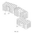
- Another embodiment of the present inventionprovides an assembly having a first spinal cage, a second spinal cage, and a spacer between the cages. At least one of the cages is provided with a spin-plate.
- kitswith a spinal cage and a spin plate.
- the spin platebeing suitable to engage with the spinal cage.
- the kitmay also be provided with a filler piece.
- Yet another embodiment of the present inventionprovides a spinal cage and filler piece assembly.
- the assemblyis provided with a spinal cage with an internal space, and a filler piece with a geometry to be placed in the internal space.
- Another embodiment of the present inventionprovides a spinal cage with at least three instrumentation interfaces on an external surface. Each of the instrumentation interfaces being configured for use with a different surgical approach.
- Another embodiment of the present inventionprovides a spinal cage with at least two instrumentation interfaces on an external surface. Each of the instrumentation interfaces being configured for use with a different surgical approach.
- Another embodiment of the present inventionprovides an installation set having a spinal implant with a rotatable member, a first installation tool and a second installation tool.
- the first installation toolis engageable with the spinal implant and the second installation tool is capable of turning the rotatable member.
- Another embodiment of the present inventionprovides a surgical procedure with a first step of creating a first surgical approach.
- Another embodiment of the present inventionprovides a trial piece for spinal surgery having a rigid body and a deployable member.
- Another embodiment of the present inventionprovides another surgical procedure that is provided with a trial piece having a deployable member and a spinal cage with a deployable member.
- the procedureis provided with the steps of: implanting the trial piece and deploying its deployable member; retracting the deployable member and removing the trial piece; implanting the spinal cage and deploying its deployable member.
- Another embodiment of the present inventionprovides a spinal cage assembly with a spinal cage, a spin-plate, and a gear associated with the spin-plate.
- Another embodiment of the present inventionprovides an installation tool for a spinal cage with a deployable member.
- the toolis provided with a first member for interfacing with the spinal cage and a second member for interfacing with the deployable member.
- the spinal cage assemblyis provided with a spinal cage, a spin-plate rotatable with respect to the spinal cage.
- the installation toolis capable of engaging the spinal cage and further capable of engaging the spin-plate and rotating the spin plate relative to the spinal cage.
- a spinal cagethat has features to receive the ends of a spin-plate and also has one or more screw holes capable of accepting a bone screw.
- the spin-platewhen the spin-plate is installed in the spinal cage and is in a stowed position, at least a portion of the screw hole(s) is blocked by the blade of the spin-plate, and when the spin-plate is deployed, the screw hole(s) is/are unblocked or less blocked.
- Such a spinal cagecan be implanted with neither a spin-plate nor a bone screw, or with a spin-plate, or with one or more bone screws, or with both a spin-plate and one or more bone screws.
- An embodimentincludes a kit containing at least one spinal cage, at least one spin-plate, and bone screws, which can be used together in various combinations.
- An embodimentincludes the method of implanting into a patient a spinal cage, comprising a spin-plate in a stowed position; rotating the spin-plate to a deployed position; and inserting at least one screw extending through the spinal cage and into an adjacent vertebra.
- Another embodiment of the present inventionprovides a cutaway feature in either the rib or the wall such that the cutaway feature comprises a central cutaway region and a connection cutaway region, and the connection cutaway region connects the central cutaway region with an external surface of the rib or wall, and the connection cutaway region has a longitudinal direction from the central cutaway region to an exterior of the rib and has a transverse direction orthogonal to the longitudinal direction, and the central cutaway region has a minimum width in the transverse direction and the central cutaway region has a maximum width in the transverse direction, wherein the minimum width of the connection cutaway region is smaller than the maximum width of the central cutaway region.
- Yet another embodiment of the inventionprovides a spinal cage, containing a rib that defines two cavities within the spinal cage, and having two holes one through the wall and one through the rib, that allow injection of material into the two cavities sequentially after the spinal cage has been implanted into a patient.
- FIG. 1is a three-dimensional view, showing an assembly of the invention in place between vertebrae of a patient's spine.
- FIG. 2is a three-dimensional illustration of a spinal cage.
- FIG. 3is a side view of a spinal cage illustrating lordosis angle.
- FIG. 4 ais a top view of the spinal cage.
- FIG. 4 bis a cross-section of the spinal cage, in a plane perpendicular to the longitudinal direction of the spinal cage.
- FIG. 5is a three-dimensional view of the spinal cage describing groove details.
- FIG. 6 ais a three-dimensional illustration of a spinal cage illustrating features for interfacing with an installation tool.
- FIG. 6 bis a cross-section of FIG. 6 a.
- FIG. 7 ais a three-dimensional illustration of the spinal cage for purposes of orienting FIG. 7 b and FIG. 7 c .
- FIG. 7 bis a three-dimensional illustration that is a close-up of a feature on one internal surface of the spinal cage, for interacting with the spin-plate.
- FIG. 7 cis a three-dimensional illustration that is a close-up of a feature on another internal surface of the spinal cage, for interacting with the spin-plate.
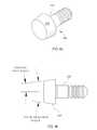
- FIG. 8 ais a three-dimensional illustration of a post for the spinal cage.
- FIG. 8 bis a side view of the same post.
- FIG. 9 ais a three-dimensional illustration of the spin-plate.
- FIG. 9 bis a three-dimensional illustration of the spin-plate from another perspective.
- FIG. 9 cis an end view of the spin-plate.
- FIG. 10 a and FIG. 10 billustrate details of the shape of the disc.
- FIG. 11is a three-dimensional view of a spin-plate having optional fenestration openings.
- FIG. 12is a three-dimensional view of the spin-plate in a position in that it is about to be installed into the spinal cage.
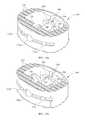
- FIG. 13 ais a three-dimensional view of the assembled spinal cage and spin-plate, with the spin-plate in the neutral position.
- FIG. 13 bis a three-dimensional view of the assembled spinal cage and spin-plate, with the spin-plate in the engaged position.
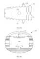
- FIG. 14 ais a front view of the assembled spinal cage and spin-plate, with the spin-plate in the engaged position.
- FIG. 14 bis a rear view of the assembled spinal cage and spin-plate, with the spin-plate in the engaged position.
- FIG. 15 ais a side view of the assembled spinal cage and spin-plate, with the spin-plate in the engaged position.
- FIG. 15 bis a top view of the assembled spinal cage and spin-plate, with the spin-plate in the engaged position.
- FIG. 16 ais a view, looking along the shaft direction of the spin-plate, of the disc interacting with the posts in the neutral position.
- FIG. 16 bis a view, looking along the shaft direction of the spin-plate, of the disc interacting with the posts in the engaged position.
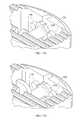
- FIG. 17 ais a localized three-dimensional view of the disc interacting with the posts in the neutral position.
- FIG. 17 bis a localized three-dimensional view of the disc interacting with the posts in the engaged position.
- FIG. 18is a three-dimensional view showing the disc interacting with the posts, in the neutral position. In this Figure, the spinal cage has been removed for clarity.
- FIGS. 19 a - 19 dshow interactions between the disc and the posts for a slightly different contour of the disc.
- FIG. 20shows an installation tool connected with a spinal cage assembly.
- FIG. 21is a three-dimensional view showing the tip of the installation tool ready to interact with the spinal cage assembly, in this case at the anterior face of the spinal cage assembly.
- FIG. 22 ais a three-dimensional view showing an installation tool almost connected to the spinal cage assembly for an anterior insertion.
- FIG. 22 bis a three-dimensional view showing an installation tool connected to the spinal cage assembly for a lateral insertion.
- FIG. 22 cis a three-dimensional view showing an installation tool almost connected to the spinal cage assembly for an anterolateral insertion at an orientation 45 degrees removed from anterior.
- FIG. 22 dis a three-dimensional view showing an installation tool almost connected to the spinal cage assembly for an anterolateral insertion at an orientation 55 degrees removed from anterior.
- FIG. 23is a three-dimensional view of a locker tool that can be inserted centrally in the installation tool for purposes of rotating the spin-plate.
- FIG. 24is a three-dimensional view of the locker tool about to be inserted centrally in the installation tool for purposes of rotating the spin-plate.
- FIG. 25 ais a three-dimensional view of the installation tool with the locker tool inserted in it, all connected to a spinal cage assembly, with the blade in the neutral position.
- FIG. 25 bis a three-dimensional view of the installation tool with the locker tool inserted in it, all connected to a spinal cage assembly, with the blade in the engaged position.
- FIG. 26is various three-dimensional views of a filler piece that might be placed in the empty space inside the spinal cage, when the spin-plate is present.
- FIG. 27illustrates a surgical procedure using one approach for introduction of the spinal cage assembly and another approach to cause rotation of a member of the spinal cage assembly.
- FIGS. 28 and 29illustrate spinal cage assemblies that contain gears to re-orient rotational motion delivered to the spinal cage assembly by a tool.
- FIG. 30is a perspective view of an embodiment of the invention, showing the spinal cage in isolation.
- FIG. 31Ais a perspective view of an embodiment of the invention, showing the spinal cage and the spin-plate in its undeployed position, without the presence of bone screws.
- FIG. 31Bis a perspective view of an embodiment of the invention, showing the spinal cage and the spin-plate in its deployed position, and further showing two bone screws.
- FIG. 32Ais a front view of the device of FIG. 31B , with the spin-plate omitted for clarity.
- FIG. 32Bis a top view of the device of FIG. 31B , with the spin-plate omitted for clarity.
- FIG. 32Cis a side view of the device of FIG. 31B , with the spin-plate omitted for clarity.
- FIG. 33Ais a sectional view of the device of FIG. 31B , with the sectional plane coinciding with one of the main planes of a bone screw.
- FIG. 33Bis a close-up of FIG. 32A .
- FIG. 34Ais a sectional view (as defined in FIG. 31B ) similar to FIG. 32A , but with the bone screw omitted.
- FIG. 34Bis a sectional view (as defined in FIG. 31B ) similar to FIG. 33A , but with both the bone screw and the snap-ring omitted.
- FIG. 35Ais a sectional view of the snap-ring alone.
- FIG. 35Bis a perspective view of a bone screw together with its snap-ring.
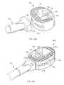
- FIG. 36is a three-dimensional perspective view of a spinal cage that includes a rib, and can receive a spin-plate with one end at the wall and the other end at the rib.
- FIG. 37is a three-dimensional perspective view similar to that of FIG. 36 , but from a different vantage point.
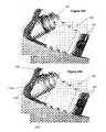
- FIG. 38Ais a three-dimensional perspective view similar to that of FIG. 37 , but also showing a spin-plate about to be inserted, with the spin-plate in a rotational position suitable to be inserted, which corresponds to a stowed (undeployed) rotational position of the spin-plate.
- FIG. 38Bshows the same spinal cage and spin-plate of FIG. 38A , assembled.
- FIG. 39is a three-dimensional perspective view of the spinal cage and spin-plate assembled together, with the spin-plate showed in a deployed position.
- FIG. 40is a three-dimensional perspective view similar to FIG. 39 , but showing only the spin-plate and the frustoconical post, with the spin-plate showed in a deployed position.
- FIG. 41Ais a three-dimensional perspective view of a spinal cage and spin-plate similar to that of FIG. 39 , but the details of the spin-plate are such that the stowed position of the spin-plate has the blade in a non-horizontal position.
- FIG. 41Bshows the spin-plate of FIG. 41A , viewed from a vantage point opposed to the vantage point of FIG. 41A .
- FIG. 41Cis a three-dimensional perspective view of the spinal cage and spin-plate of FIG. 39 , but with the spin-plate deployed.
- FIG. 42Ais a sectional view of the spinal cage and spin-plate with the blade undeployed, as shown in FIG. 38B .
- FIG. 42Bis a sectional view of the spinal cage and spin-plate with the blade deployed, as shown in FIG. 39 .
- FIG. 43is a three-dimensional view of an alternate version of spinal cage similar to that of FIG. 38A , but wherein the rib has a groove rather than a slot.
- FIG. 44is a close-up three-dimensional view of an end of the spin-plate.
- FIG. 45is a close-up three-dimensional view of the spin-plate received in the spinal cage.
- FIG. 46is a three-dimensional perspective view of yet another embodiment of the invention, showing a spinal cage that contains a rib and holes that allow for the introduction of material.
- An embodiment of the inventionincludes a spinal cage and a deployable member that can removably fit inside the spinal cage.
- the deployable membermay be a spin-plate that is able to rotate in order to be deployed.
- the spinal cagemay be implanted in a patient either with or without the deployable member.
- FIG. 1illustrates a spinal cage assembly 10 placed between adjacent vertebrae 70 and 72 .
- Spinal cage 100is illustrated in FIGS. 2-8 .
- Spinal cage 100may have a longitudinal direction that extends generally from vertebra to vertebra 70 , 72 in the installed situation.
- Spinal cage 100may have a longitudinal dimension and related geometry that imposes the desired relative positioning between vertebrae 70 and 72 when the spinal cage 100 is in place in the patient. This positioning may include a lordosis angle, which is an angle indicating the extent of non-parallelism between planes enveloping the two ends of the spinal cage.
- spinal cage 100may comprise a wall 110 extending in the longitudinal direction of the spinal cage 100 between vertebrae 70 and 72 .
- wall 110may progress circumferentially in a closed curve that may at least approximately fit within an envelope of a vertebral cross-section.
- the closed curve of the wall 110may define an interior space 112 inside wall 110 .
- the interior space 112 of spinal cage 100may be substantially open space, available for the placement of materials conducive to bone ingrowth or for eventual bone ingrowth.
- the spinal cage 100may be generally prismatic having a prismatic axis, which is the longitudinal axis of the spinal cage 100 , and having a cross-section perpendicular to the prismatic axis. Along the prismatic axis, features of spinal cage 100 may generally be constant or repeated.
- the spinal cage 100may have a height along the prismatic direction, but it is not necessary for either the external height of spinal cage 100 or the internal height of spinal cage 100 in the prismatic direction to be uniform everywhere.
- the spinal cage 100may be wedge-shaped such that the two end faces 114 of spinal cage 100 are not parallel to each other, as described in connection with lordosis and as illustrated in FIG. 3 .
- spinal cage 100may be missing or features may be cut into what would otherwise be a strictly prismatic shape.
- end faces 114 of spinal cage 100may have teeth or grooves or other local features that are not strictly prismatic.
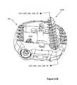
- FIG. 4a representative cross-section of spinal cage 100 , taken perpendicular to the prismatic axis, is illustrated. This may be considered to be a cross-section of spinal cage 100 that does not encounter any special isolated features described elsewhere herein, such as openings, endplate features, or instrumentation interface features.
- a wall thickness of wall 110may be defined as one traces a path around the internal perimeter. At each point on the internal perimeter, the wall thickness is defined by a distance to a nearest corresponding point on the outer perimeter of the spinal cage 100 .
- the wall thickness as a function of position on the internal perimetermay be such that nowhere along the perimeter is there a constant wall thickness, but rather the wall thickness varies continuously as a function of position along the perimeter of the spinal cage 100 .
- the described cross-section of spinal cage 100may have an external perimeter.
- the external perimetermay comprise four main curved segments 117 a , 117 b , 117 c , 117 d , and additionally may comprise corner radii 118 where the various main curved segments join other main curved segments, thereby comprising a total of eight curved segments connected in succession. Corner radii 118 can be identical to each other or different.
- the external perimeter of wall 110may approximate an outline that somewhat resembles the shape of an intervertebral disc, such as, for example, the closed curve of the wall 110 may approximate a kidney-bean shape. Still other shapes of external perimeter are also possible.
- the described cross-section of spinal cage 100may have an internal perimeter.
- the interior perimetermay comprise at least two substantially straight-line segments, which may be opposed to each other and may be parallel to each other.
- the interior perimetermay comprise four substantially straight-line segments 119 a , 119 b , 119 c , 119 d at least some of which may be separated from other similar segments by rounded corner segments 119 e .
- two opposed substantially straight-line segmentsmay have lengths substantially equal to each other. These two segments may be parallel with each other.
- the other two opposed segmentsmay have lengths different from each other. These two opposed segments may be parallel with each other.
- the longer of these lengthsis labeled L1 and the shorter of these lengths is labeled L2.
- the end faces 114 of spinal cage 100may be roughened or have features appropriate to bite into the bone of adjacent vertebrae 70 , 72 .
- Groovesmay be oriented so that it is relatively easy to insert the spinal cage 100 into an intervertebral disc space in the desired direction of insertion, and relatively more difficult to move the spinal cage 100 in the opposite direction.
- the walls of the groovesmay slope backwardly with respect to the intended direction of advancement.
- the illustrationshows grooves that extend substantially laterally across a full width of the end surface of the spinal cage 100 , this is not necessary. It is also possible to have teeth or still other geometries at end surfaces of spinal cage 100 .
- the wall 110may comprise a flat plane on its interior surface that faces interior space 112 .
- the flat planemay be substantially a laterally oriented plane, perpendicular to the anterior-posterior direction of the spinal cage 100 . This is illustrated in FIG. 5 . If the plane of that interior surface is projected laterally so as to intersect the entire spinal cage 100 , that plane will divide the spinal cage 100 into a region that is posterior of the plane and a region that is anterior of the plane. It is possible that the region of wall 110 that is posterior of that plane may have, on its top and bottom surfaces, a tapered surface that is uninterrupted by grooves or teeth. The grooves or teeth may exist anteriorly of that plane.
- spinal cage 100may comprise an opening 120 through the wall 110 , with the opening 120 having an opening axis. Opening 120 may be a through-hole through the wall 110 . Opening 120 may be located on a plane of symmetry of spinal cage 100 , or at the intersection of two planes of symmetry. Opening 120 may be internally threaded for a portion of its length. Opening 120 may be of a diameter suitable to provide access for a rotational tool for rotating the spin-plate 200 as described elsewhere herein, or for any other desired purpose.
- Spinal cage 100may further comprise an opposed concave feature 130 located in a part of wall 110 that is opposed to the location of opening 120 . Opening 120 and opposed concave feature 130 may be coaxial. Opposed concave feature 130 may have a center of symmetry (such as a line axis of symmetry or a point of symmetry) that is a center of symmetry for at least some features of opposed concave feature 130 , and that center of symmetry may lie along the opening axis of opening 120 .
- a center of symmetrysuch as a line axis of symmetry or a point of symmetry
- Opposed concave feature 130may comprise any one or more of a recess, or a shaft-receiving blind opening or a shaft-receiving through hole, in any combination. Opposed concave feature 130 , or at least a portion thereof may be symmetric about the center of symmetry.
- opening 120 and opposed concave feature 130could be through-holes, and that one or both of opening 120 and opposed concave feature 130 could be stepped openings or otherwise have a configuration more complicated than a simple cylindrical opening.
- opening 120 and opposed concave feature 130or a recess associated with either or both of 120, 130 might have a periphery that is not completely circular or is non-axisymmetric.
- Opening 120 and opposed concave feature 130 taken togethermay be suitable to define a position or an axis of a shaft of a spin-plate as described elsewhere herein.
- opening 120may be at the anterior of the spinal cage 100 and opposed concave feature 130 may be at the posterior of the spinal cage 100 . Opening 120 may be adapted for use in interfacing with an installation tool, as described elsewhere herein.
- the spinal cage 100may have a groove 150 or two grooves 150 , 160 that extend at least approximately in the longitudinal direction of the spinal cage 100 .
- the groove or grooves 150 , 160may be on an interior-facing surface of the wall 110 of spinal cage 100 . If there are two grooves 150 , 160 , the grooves 150 , 160 may be located so that they substantially face each other.
- the groove(s) 150 , 160may extend from features 120 , 130 all the way to one end of the spinal cage 100 . If there are two grooves 150 , 160 , the grooves 150 , 160 may be substantially parallel to each other and may extend in the same direction as each other.
- the grooves 150 , 160are shown as being straight although they do not have to be straight. In one embodiment, the grooves 150 , 160 may be located such that their respective axes lie in a plane that is a plane of symmetry of the spinal cage 100 .
- a groove 150 , 160may comprise an entrance region such as a tapered or curved entrance region 156 that may help the end of a component entering groove 150 , 160 to find its appropriate place while accommodating inexact initial placement of the component with respect to groove 150 , 160 .
- the two grooves 150 , 160may be identical to each other or they could be different from each other.
- grooves 150 , 160may have respective groove widths that are different from each other. This may help to create a situation in which there is only one possible way for a spin-plate to be installed into the spinal cage 100 . Such a situation may be desirable for preventing possible mistakes of assembly or procedure. Having grooves 150 , 160 be different from each other may be appropriate to accommodate differences between the two ends of the spin-plate in terms of function or dimensions of the respective shaft ends, as discussed elsewhere herein.
- the spinal cage 100may comprise an installation tool interface for an insertion tool to connect to the spinal cage 100 during installation.
- the installation tool interfacemay define an insertion direction that may be at least approximately perpendicular to the local surface of the spinal cage 100 at the place where the insertion tool connects to the insertion tool interface.
- the insertion directionmay be at least approximately parallel to the axis of the opening 120 , which in turn may correspond to the axis of rotation of the spin-plate (described elsewhere herein) when the spin-plate is installed in the spinal cage 100 .
- This designcould be used if the surgical approach for placement of the spinal cage 100 is an anterior surgical approach.
- the axis of the opening 120could lie in a plane of symmetry of the spinal cage 100 .
- the spinal cage 100could be designed for use with surgical approaches other than a straight anterior approach.
- the spinal cage 100could be designed for use with a lateral surgical approach.
- Still other surgical approachesmay be possible, with corresponding choices of locations of opening 172 .
- FIGS. 6 a , 6 billustrate a spinal cage 100 that comprises interface features compatible with four different surgical approaches.
- the spinal cage 100may comprise a plurality of interface features 172 , such as openings on an external surface of the spinal cage 100 , with an interface feature 172 corresponding to each possible surgical approach.
- an interface featuresuch as an opening 172 a in the anterior surface of the spinal cage 100 , for use with an anterior approach.
- an interface featuresuch as an opening 172 b in the lateral surface of spinal cage 100 , for use with a lateral approach.
- Interface feature 172 bmay be located approximately 90 degrees away from opening 172 a , as viewed in FIG. 6 .
- an opening 172 cthrough the external surface of the spinal cage 100 oriented at approximately 45 degrees away from the anterior direction.
- an instrumentation interfacemay be provided for insertion of the spinal cage 100 from a direction that is closer to anterior than it is to any other direction, but is still somewhat removed from anterior.
- the directionmay be oriented approximately 15 degrees removed from anterior.
- the opening 172 dmay be translationally offset from a true 15 degree opening pointing at the center of the spinal cage 100 , so as to avoid overlap with other features of spinal cage 100 with which overlap might occur without such offset.
- the 45 degree interface opening 172 c and the 15 degree interface opening 172 dmay be provided on opposite sides of the anterior interface opening 172 a , again to avoid overlap of such openings with each other.
- interface openings 172may be internally threaded. It is further possible that an interface opening, such as 172 a , may have interface features such as an internal thread. These threads may occupy only a portion of the depth of opening 120 that may be coaxial with 172 a . Such threads may be on a more exterior portion of opening 172 a . At the same time, opening 172 a may comprise features that interface with a spin-plate as described elsewhere herein. Such features may be on a more interior portion of opening 172 a . The portion of opening 172 a that interfaces with the spin-plate may be free from threads. The threads on some of the interface openings 172 may be identical to the threads on some other interface openings 172 .
- threads on some interface openingsmay be different from the threads on other interface openings.
- threads on opening 172 awhich is illustrated as being a multi-purpose opening, may be larger than threads on openings 172 b , 172 c , 172 d , which are illustrated as serving only as instrumentation openings.
- a groove 174may be provided on the external surface of the spinal cage 100 , extending so as to meet at least some or (as illustrated) all of these interface openings 172 .
- the groove 174may be located at least approximately on a plane of symmetry of spinal cage 100 , such as the midplane of the spinal cage 100 , such plane being perpendicular to the prismatic axis of the spinal cage 100 .
- This groove 174 on the exterior surfacemay extend more than 90 degrees of angle progressing around the external perimeter of spinal cage 100 , such as extending through at least approximately 135 degrees of circumference.
- the groove 174may cooperate with a corresponding feature on an installation tool.
- groove 174may cooperate with a feature of an installation tool to serve an anti-rotation function.
- Various different spinal cages 100 of different sizesmay be designed so that at least some of them share the same installation tool interface.
- curvature of the spinal cage external surface near the tool interfacesuch as curvature of the spinal cage external surface near the tool interface, dimensions of the tool interface groove 174 , dimensions of interface openings 172 a , 172 b , 172 c , 172 d , etc.
- an installation toolcan interface with multiple size variations of spinal cages 100 .
- Dimensions of the spinal cage 100 or of various spinal cages in a setmay include an overall height that ranges from 8 to 16 mm, footprint dimensions that range from 27 mm to 39 mm in width and 21 mm to 30 mm in depth, and lordosis angles that range from 8 degrees to 15 degrees.
- the set of spinal cage sizesmay for example comprise a typical small size and a typical large size, with most patients being able to accept one or the other of those two sizes. There may further be provided an extremely large size and an extremely small size for patients needing those particular sizes.
- a variety of spinal cagesmay be provided having respective combinations of heights and lordosis angles.
- the spinal cage 100may comprise one or more posts 190 that may protrude from the spinal cage wall 110 into the interior space 112 of the spinal cage 100 .
- the rotation centermay be the center of feature 130 or on the axis of opening 120 .
- a simple possible form of post 190is a cylindrical post, part of which is embedded in wall 110 , and part of which protrudes into the interior space 112 of spinal cage 100 .
- the post 190may comprise a stem 192 and a head 194 , with the head 194 being larger in a transverse direction than is the stem 192 .
- the stem 192 and the head 194may be substantially coaxial, although this is not necessary. It is possible that the entire post 190 may be axisymmetric, although this is not necessary.
- the post 190may be cylindrical where it engages the spinal cage 100 , and it may be cylindrical with a larger diameter where it does not engage the spinal cage 100 .
- the post 190may protrude into interior region 112 of spinal cage 100 at the portion that does not engage the spinal cage. It is appreciated that shapes other than cylindrical are also possible for post 190 .
- the stem 192may be capable of being embedded into the spinal cage.
- the stem 192may fit with a press fit or an interference-fit within an opening in the spinal cage wall 110 .
- the stem 192may further comprise barbs or similar features that may be oriented in such a direction that inserting the stem 192 into the spinal cage wall 110 is relatively easier than removing the stem 192 from the spinal cage 100 .
- posts 190could be molded into spinal cage 100 .
- the postcould be integral with the wall 110 of spinal cage 100 .
- the head 194 of the post 190may be frustoconical. If frustoconical, the head 194 may have a head taper angle as illustrated, with the head being larger nearest to the wall 110 and smaller away from wall 110 .
- the taper angle of the frustoconical head 194may be chosen for purposes of interaction with features of the spin-plate, as described elsewhere herein. For example, a possible angle of taper of the frustoconical head 194 is approximately 15 degrees total included angle (7.5 degrees conical half-angle).
- This anglemay be chosen appropriately so that when spin-plate 200 is in place, the frustoconical angle of the head 194 , and a corresponding angle near the edge of the disc 290 that interacts with post 190 , combines to trap post 190 in position in wall 110 .
- This structuremakes it impossible for post 190 to migrate out of the wall opening in which it is inserted.
- the cooperating anglesas spin-plate 200 is rotated, may urge spin-plate 200 forward possibly making some elastic deformation of spinal cage 100 available to help the rotation slip past certain detents in the normal course of rotation.
- wall 110 of spinal cage 100can be deflectable within an elastic limit such that under certain circumstances, the shape of the closed curve of wall 110 becomes slightly different from what it is in an undeflected-condition.
- wall 110can be deflectable in an anterior-posterior direction such that the distance between the anterior and posterior portions of the wall 110 increases.
- the amount of deflectioncan be suitable for snapping a spin-plate into place or can be involved in rotating the spin-plate, both of which are described elsewhere herein.
- the wall 110may be generally straight along the prismatic direction, with the possible exception of local geometric features.
- the wallmay be straight both interiorly and exteriorly.
- the wall 110 of the spinal cage 100may have an inner surface (facing interior space 112 ) that is concave along a longitudinal direction from a first end to a second end of the spinal cage 100 .
- Such a concave inner surfacemay provide increased space for bone ingrowth or for placement of material for aiding the ingrowth of bone, as compared to a wall 110 whose inner surface is substantially straight or prismatic.
- the spinal cage 100may be chosen to have a desired radiopacity.
- the spinal cage 100may be made entirely or mostly of radiolucent material such as a polymer (for example, polyetheretherketone (PEEK)).
- PEEKpolyetheretherketone
- the spinal cage 100could additionally comprise radiopaque markers placed in it at desired locations having known dimensions, spacing or orientation for later use during radiography.
- the radiopaque markerscould be or could comprise tantalum.
- the radiopaque markerscould be in the form of spheres, rods or other simple shapes.
- the radiopaque markerscould be press-fitted into appropriate cavities in spinal cage 100 .
- radiopaque markerscould be molded into spinal cage 100 .
- the radiopacity of the spinal cage 100may be chosen in combination with the radiopacity of the spin-plate 200 to achieve a desired purpose.
- Embodiments of the inventioncan include a spin-plate 200 or more generally a deployable member.
- Spin-plate 200is illustrated by itself in FIGS. 9-11 .
- the spin-plate 200may comprise a shaft 210 and a blade 230 .
- Blade 230may, as illustrated, be a substantially planar element that may have some sharpened edges.
- the plane of blade 230may be substantially perpendicular to the axis of shaft 210 .
- the blade 230 and the shaft 210may be sized to fit inside spinal cage 100 for certain rotational positions of spin-plate 200 , and to extend beyond the envelope of spin-plate 200 for other rotational positions of spin plate 200 .
- the blade 230may be integral with shaft 210 .
- blade 230may be made as a separate part from shaft 210 and may be connected to shaft 210 either temporarily or permanently. It is possible that if the shaft 210 and the blade 230 are not made integrally with each other, they might be made separately from each other in such a way that a surgeon would have the ability to select and assemble blade 230 and shaft 210 to each other as desired at around the time of surgery. There may be, as illustrated, only one blade 230 . Alternatively, it is possible that the spin-plate 200 could comprise or could be used with more than one blade 230 simultaneously. If so, the various blades 230 either could be identical to each other or could differ from each other in their dimensions, materials or in any other feature.
- the position of blade 230 on spin-plate 210could be chosen so as to provide a desired position of the blade 230 with respect to anatomical features such as regions or types of bone within a vertebra. If the blade 230 is near the middle of the length of spin-plate 210 , blade 230 when deployed is likely to interact with cancellous bone. If blade 230 is closer to and end of spin-plate 210 , blade 230 when deployed is more likely to interact with cortical bone. The position of spin-plate 230 on shaft 210 also may affect how much spreading-apart of the vertebrae could be acceptable at the location of blade 230 .
- Blade 230could have an edge, which is the leading edge for the intended direction of rotational advancement of the blade into bone that is sharpened but otherwise smooth and continuous, as illustrated in FIG. 9 and elsewhere.
- the blade 230could comprise serrations or a plurality of teeth on surfaces that face bone for an intended possible direction of rotation for advancing the blade 230 into the bone. Such serrations or teeth may help provide suitable properties for cutting into bone.
- the blade 230could comprise at least one opening through the blade 230 or at least one indentation from an edge of the blade 230 . Such openings or indentations could provide shape irregularities that newly formed bone can grow through or into or around, thereby helping to anchor the blade 230 in position in the patient after bone ingrowth has occurred.
- the blade 230in cross-section in a plane that includes an axis of rotation of the shaft 210 , could comprise an undercut configuration. Such a configuration could also contribute to anchoring of the blade 230 and the spin-plate 200 generally into bone.
- the spin-plate 200may have respective dimensions in directions that are radial or perpendicular to the axis of rotation of spin-plate 200 .
- the shaft 210may have a dimension such as a shaft diameter that is less than a corresponding maximum radial dimension of the blade 230 .
- Shaft 210may comprise flats on the shaft on at least one end or both ends of the shaft 210 .
- An end of shaft 210could have geometry as illustrated in FIG. 9 and elsewhere, comprising circular arcs and flats.
- the flats 222 a , 222 b and 232 a , 232 bmay be parallel with each other.
- Flats at opposite ends of shaft 210also may be parallel with each other.
- the end of shaft 210could have still other geometries instead of the described circular arc and flats.
- the end of the shaftmay be non-axisymmetric.
- An end of shaft 210may comprise a cross-section that is non-circular having, at various lines passing through the axis perpendicular to the axis, a smallest cross-dimension of the enlargement 250 and a largest cross-dimension of the enlargement 250 .
- the orientation of the smallest cross-section dimensionmay be approximately perpendicular to the orientation of the largest cross-section dimension.
- the spin-plate 200may be able to pass translationally longitudinally through groove 150 , 160 for certain angular orientations of spin-plate 200 with respect to spinal cage 100 , while being unable to pass through groove 150 , 160 for other angular orientations.
- the shaft 210might comprise a rotational tool interface 280 suitable to transmit rotation from a tool to the spin-plate 200 .
- Rotational tool interface 280could be provided either at one end or at both ends of spin-plate 200 .
- a rotational tool interface 280 for a rotational driving toolis not needed at both ends of shaft 210 , but rather is only needed at one end.
- the shaft 210may be designed accordingly.
- the rotational tool interface 280could be elongated such as a rectangle or rounded-rectangle.
- the long direction of the elongated tool interfacecould be parallel to the flats on the shaft 210 or flats on an enlargement of the shaft 210 at that end of the shaft 210 .
- a feature at one end of the shaft 210may be different from a feature at the other end of the shaft 210 .
- the differencemay be in a width of a flat at or near an end of the shaft 210 , or more generally may be a smallest cross-section dimension of the enlargement 250 .
- such a featuremay have a function in determining whether a spin-plate 200 can be inserted into the spinal cage 100 in only one configuration or whether a spin-plate 200 can be inserted in two configurations by reversing the ends of the spin-plate 200 . In some circumstances, it may be useful if the spin-plate 200 fits into the spinal cage 100 in only one configuration.
- the spin-plate shaft 210may for at least for a portion of its length be hollow.
- the shaft 210may have a hollow interior 214 that is open at the end having tool interface feature 280 , and that may be closed at the end opposite the open-ended end.
- theremay be fenestrations 216 that may be at least approximately transverse to the rotational axis of shaft 210 .
- the fenestrations 216may be at least approximately perpendicular to the rotational axis of shaft 210 .
- the fenestrations 216may be suitable to allow passage of bone-growth-promoting material or other liquid or semi-solid material.
- the end of the shaft 210at which the hollow interior 214 is accessible, may be the end that is most accessible to the surgeon. Such as, for example, the end that has an interface 280 to accept tooling to cause rotation of the spin-plate 200 .
- This end of the shaft 210may further comprise a feature to interface with an injection device for injecting bone growth promoting material or other material into the shaft interior 214 .
- Fenestrations 216 through the side wall of the shaft 210may exit the shaft 210 in such an orientation that, when the spin-plate 200 is in its final position in which the blade 230 is deployed to interact with adjacent vertebrae, the fenestrations 216 point laterally in the patient's body. Similarly, it is possible that the fenestrations 216 may point in an oblique direction, partly laterally but also having a component in the cephalad-caudal direction. In the illustration, spin-plate 200 is illustrated in its orientation in which the blade 230 is deployed to interact with adjacent vertebrae.
- the spin-plate 200may be designed to have a desired radiopacity for a specific purpose.
- the radiopacity of spin-plate 200may be chosen in combination with the radiopacity of the spinal cage 100 .
- the shaft 210 and the blade 230could be made of the same material and may even be integral with each other.
- the entire spin-plate 200could be made of metal such as a biocompatible titanium alloy.
- spin-plate 200could be chosen for radiographic purposes. It is possible that some part of the spin-plate 200 could be more radiopaque than another part of the spin-plate 200 .
- the shaft 210could be more radiopaque than a remaining part of the spin-plate, or the blade 230 could be more radiopaque than a remaining part of the spin-plate 200 . If multiple blades 230 are present, individual blades 230 could have different radiopacities.
- the blade 230 of spin-plate 200may have a coating of a substance that is a member of the calcium phosphate family.
- the coatingmay comprise hydroxyapatite or tricalcium phosphate.
- Such substancescan be deposited onto a substrate, for example a metal substrate such as the blade 230 of spin-plate 200 , by methods such as plasma spraying.
- Such coatingsmay promote the growth and interaction of bone with the component that they are deposited upon.
- Some deployable partsmay be resorbable.
- the blade 230or some portion thereof, may be resorbable.
- the blade 230may, for example, comprise a resorbable polymer. If the blade 230 is resorbable, it is still possible that shaft 210 may be nonresorbable. Similarly, some portion of blade 230 may be nonresorbable.
- the resorption time of the resorbable deployable partmay be chosen so that the deployable part stays intact while bone growth is occurring and while there may be some risk of expulsion of the spinal cage. But, by the time resorption has completed, bone growth has occurred sufficiently to achieve fusion between the desired vertebrae.
- Use of a resorbable deployable partneed not be limited to the described design involving spin-plate 200 , but could be used as well with other designs of spinal fusion cages having deployable members that may be deployable by any form of motion.
- the spin-plate blade 230may be located so as to cut into cancellous bone in adjacent vertebrae rather than into cortical bone, because the cancellous bone might be easier to cut into.
- the spin-plate blade 230comprises resorbable materials
- the blade 230might be less tough than would be the case for a metal blade, and so the blade 230 might be located so as to cut into cancellous bone.
- Spin-plate blade 230if it is not itself radiopaque, may comprise a radiopaque marker.
- Embodiments of the inventionmay include an assembly comprising the spinal cage 100 and the spin-plate 200 .
- FIGS. 12-15illustrate assemblies or features thereof.
- the spin-plate 200 and the spinal cage 100may be separable from each other.
- Spinal cage 100may be suitable to be implanted in a patient either with or without spin-plate 200 as dictated by surgical needs.
- the spinal cage 100may have an internal perimeter whose shape is as illustrated in FIG. 4 .
- the use of a sharper radius of curvature and the longer of the two unequal segments L1 compared to L2may occur on the face nearest where the spin-plate blade 230 exists in the assembly. This may provide space for the blade 230 to rotate and may help to allow blade 230 to be as long as possible within geometric constraints of the overall spinal cage 100 and the assembly.
- the spinal cage 100is assembled with a corresponding spin-plate 200
- the lateral dimension of the longer flat of the internal perimeter, labeled L1 in FIG. 4may be at least as large as the largest end-to-end dimension of the blade 230 on the spin-plate 200 .
- L3which is the distance between the two opposed substantially straight-line segments, may be at least as large as the largest end-to-end dimension of the blade 230 on the spin-plate 200 . This may be true for all cross-sections of spinal cage 100 or at least for a cross-section that passes through the rotational axis of spin-plate 200 .
- Various sizes of spinal cages 100 and various sizes of spin-plates 200may be manufactured and may be provided to a surgeon in advance of surgery.
- the respective spinal cages 100 and spin-plates 200may be such that various different spin-plates 200 can be inserted into a particular spinal cage 100 , depending on the choice of the surgeon.
- the various different spin-plates 200may differ from each other in some geometric feature.
- the spin-plates 200may differ in the respective lengths of their respective blades 230 , so as to provide different depths of penetration of the blade 230 of spin-plate 200 into the bone of the adjacent vertebrae.
- the dimension L1 or alternatively the dimension L3may be larger than the end-to-end dimension of the largest-bladed spin-plate that is contemplated to be used with a particular spinal cage 100 .
- the spin-plate 200 and the spinal cage 100may be such that the spin-plate 200 can be engaged with or disengaged from the spinal cage 100 without the use of a tool.
- the engagement of the spin-plate 200 with the spinal cagemay be able to be performed with a snap fit. It may also be possible to disengage the spin-plate 200 from the spinal cage by undoing the snap fit. Alternatively, a tool could be used to assist in insertion or disengagement.
- the engagement of the spin-plate 200 with the spinal cage 100may be in such a way as to provide a positive indication that the spin-plate 200 has entered the spinal cage 100 and has reached the place where rotation of the spin-plate 200 can be performed.
- the positive indicationcan be tactile, such as a sharp change in the amount of force needed to advance the spin-plate 200 into the spinal cage 100 , or audible, or both.
- the spin-plate 200may have a first end engaged with a first place on the wall 110 of the spinal cage and a second end engaged with a second place on the wall 110 of the spinal cage.
- the first place and second placemay be substantially opposed to each other. It is possible that the first and second places may be on anterior and posterior portions of the wall 110 of the spinal cage, respectively. Other spin plate locations are also possible.
- Blade 230may have a maximum end-to-end dimension that is greater than the longitudinal dimension of the spinal cage 100 in at least some places in the spinal cage 100 . This may ensure interaction of the blade 230 with bone when the blade 230 is in a deployed condition.
- Blade 230may have a side-to-side dimension that may be measured in a direction approximately perpendicular to the direction in which the blade end-to-end dimension is measured.
- the blade 230 side-to-side dimensionmay be less than a longitudinal dimension of spinal cage 100 in at least some places in the spinal cage 100 . This may ensure that when the blade 230 is in an undeployed condition, it does not interact with bone.
- the spin-plate 200may be designed so that the deployed angular position of the blade is 90 degrees removed from the undeployed angular position of the blade.
- the spin-plate 200may be capable of rotating 90 degrees away from the initial angular position in a specified direction of rotation.
- Embodiments illustrated hereinpermit 90 degrees of rotation in a specified direction of rotation, but more than 90 degrees of rotation is difficult or impossible, and rotation in the unintended direction of rotation is difficult or impossible.
- rotation of the spin-plate 200 relative to the spinal cagemight be angularly unrestricted, allowing as much as 360 degrees or more of rotation of the spin-plate 200 relative to the spinal cage 100 .
- the assemblymay be such that when the spin-plate 200 is installed in the spinal cage 100 , the interior of the spinal cage 100 is substantially open and unblocked except for the spin-plate 200 .
- the spin-plate 200 and the spinal cage 100may be designed such that the spin-plate 200 can fit into the spinal cage 100 in only one configuration (as opposed to being able to fit into spinal cage 100 with either end of spin-plate 200 in either of the two grooves 150 , 160 ). If the spinal cage comprises two grooves 150 , 160 and the spin-plate 200 comprises two corresponding flat-to-flat dimensions, the two grooves 150 , 160 can be of unequal dimensions and the flat-to-flat dimensions could be correspondingly different. As a result of this, the spin-plate 200 and the spinal cage 100 may fit together in only one configuration.
- the spin-plate 200 and the spinal cage 100may be designed so that the at one end of the spin-plate 200 , the flat-to-flat dimension of the shaft is slightly less than the width of groove 150 , and at the other end of the spin-plate 200 , the flat-to-flat dimension of the shaft is slightly less than the width of groove 160 . It may be useful for mistake-proofing if the spin-plate 200 fits into the spinal cage 100 in only one configuration. Alternatively, the various components may be designed so that the spin-plate 200 can be placed into spinal cage 100 in either end-to-end configuration.
- an end of spin-plate 200may have a non-circular cross-sectional shape having a minimum cross-sectional dimension and a maximum cross-sectional dimension.
- the minimum cross-sectional dimension of the end of spin-plate 200may be less than the width of the particular groove.
- the maximum cross-sectional dimension of the end of spin-plate 200may be less than a transverse dimension of opening 120 or opposed concave feature 130 .
- the two ends of shaft 200 and corresponding features of spinal cage 100may be substantially identical to each other.
- spin-plate 200it may be possible to install spin-plate 200 into spinal cage 100 in a first orientation or in a second orientation in which the ends of spin-plate 200 are interchanged with each other.
- the spin-plateneed not be symmetric from end-to-end.
- blade 230might be located on shaft 210 at a location that is not the midpoint of shaft 210 , and having the ability to insert spin-plate 200 into spinal cage 100 in two opposite end-to-end orientations would provide two choices for the position of the blade 230 .
- the spinal cage 100 and the spin-plate 200may be such that the spin-plate 200 can be captured within spinal cage 100 , at least for certain relative rotational positions. It is possible that when the spin-plate 200 is in the spinal cage 100 , the spin-plate 200 could experience axial force from spinal cage 100 such as from elastic deformation of spinal cage 100 . In this situation, it is possible that there could be a designed amount of axial force exerted by spinal cage 100 upon spin-plate 200 , resulting in a designed amount of friction against rotation of spin-plate 200 relative to spinal cage 100 and essentially no permitted axial motion of spin-plate 200 relative to spinal cage 100 .
- the spin-plate 200does not experience force exerted on it by spinal cage 100 along the rotational axis direction of spin-plate 200 .
- the apparatusmay be designed to lack such force if it is uncertain or unpredictable what the actual amount of such force would be. In such a structure, it is possible that there could be a slight amount of permitted axial motion (play) of the spin-plate 200 relative to spinal cage 100 along the rotational axis direction of spin-plate 200 .
- the dimensionsmight be such that nominally there is substantially no permitted axial motion of spin-plate 200 relative to spinal cage 100 and also substantially no axial force exerted by spinal cage 100 upon spin-plate 200 along the direction of the axis of rotation of spin-plate 200 .
- disc 290it is possible either for disc 290 to bear against an interior-facing surface of wall 110 or for blade 230 to bear against an interior-facing surface of wall 110 , or both. It is possible that neither disc 290 nor blade 230 bears against an interior-facing surface of wall 110 .
- the spin-plate 200can have two extreme points at least approximately corresponding to extreme ends of spin-plate 200 along the rotational axis of spin-plate 200 .
- the distance between the two nearest-contact pointscan be greater than or approximately equal to the distance between the two extreme points of the spin-plate 200 .
- the distance between the two nearest-contact points(when the spinal cage is undeformed) could be less than the distance between the two extreme points of the spin-plate 200 .
- the spinal cage 100 and the spin-plate 200may be such that spinal cage 100 is capable of deflecting within an elastic limit, by an elastic deflection distance.
- spinal cage 100is capable of deflecting within an elastic limit, by an elastic deflection distance.
- everywhere along an insertion path of spin-plate 200 into spinal cage 100there is a minimum clear dimension in a direction roughly corresponding to the axis of rotation of spin-plate 200 . That minimum clear dimension plus an elastic deflection distance, is greater than the maximum overall length of spin-plate 200 .
- the spinal cage 100 and the spin-plate 200may be such that the spin-plate 200 is capable of entering the spinal cage 100 and becoming trapped within spinal cage 100 while being able to rotate relative to spinal cage 100 after spin-plate 200 has become trapped within spinal cage 100 .
- the length of the spin-plate 200could be such that the spin-plate 200 fits into spinal cage 100 without any interference along the axial dimension and is able to rotate without any friction caused by surfaces contacting each other forcibly along the lengthwise direction.
- the ends of shaft 210 of spin-plate 200may be flat-ended as illustrated or may have a convex curvature. Opening 150 and opposed concave feature 160 could be either flat-bottomed or concavely-curved.
- the spin-plate 200may be captured in the spinal cage 100 by one or both of two types of capturing action. It is possible that one of the capturing actions may be in effect even before the spin-plate 200 has been rotated away from the angular orientation that it has during insertion into spinal cage 100 .
- the spin-plate 200 near at least one endmay have at least one flat having a local flat external width of the spin-plate 200 relative to the flat
- the spinal cagemay have at least one groove 150 , 160 having a groove internal width
- the flat external widthmay be less than or equal to the groove internal width
- the spin-plate 200may comprise a non-circular cross-section having, at various lines passing through the spin-plate rotational axis perpendicular to the spin-plate rotational axis, a smallest cross-dimension and a largest cross-dimension.
- the spinal cage 100may comprise a generally longitudinally-oriented groove 150 , 160 having a groove width, and the groove width may be intermediate between the smallest cross-dimension and the largest cross-dimension. Groove width may refer to the minimum width dimension of the groove.
- the spin-plate cross-section near at least one end of the spin-platecould be elliptical.
- the spin-plate cross-section near at least one endcould be the cross-section of an enlargement 250 , 252 or could be a cross-section of the shaft 210 itself of spin-plate 200 .
- the spin-plate 200 and the spinal cage 100may cooperate to provide at least one detent position in the rotation of the spin-plate 200 with respect to the spinal cage 100 .
- the detentmay be such that rotation past the detent is permitted, but a certain amount of torque is necessary to pass the detent position, with that certain amount of torque being larger than the amount of torque needed to produce rotation in other portions of the rotational sequence. It is possible that there can be two detent positions in rotation of the spin-plate 200 with respect to the spinal cage 100 . The two detent positions may separated by approximately 90 degrees of rotation, or by approximately 180 degrees of rotation.
- a detent positioncan correspond to the deployed configuration of the spin-plate 200 relative to the spinal cage 100 , in which blade 230 extends beyond spinal cage 100 . It is possible that a detent position can correspond to the undeployed configuration in which blade 230 is contained within spinal cage 100 . If there are two detent positions, it is possible that they can correspond to both of the just-described configurations.
- the spin-plate 200 and the spinal cage 100may cooperate to provide at least one stop position in rotation of the spin-plate 200 with respect to the spinal cage 100 .
- the spin-plate 200may become immobilized with respect to the spinal cage 100 , it may become extremely difficult or impossible to rotate the spin-plate 200 beyond the stop angular position. It is possible that when the stop position is reached, it may still be possible to rotate the spin-plate 200 backward from the stop position. It is further possible that there may be a detent at the stop position, such that reverse rotation from the stop position requires overcoming a threshold amount of torque. It is still further possible that the spinal cage assembly could have a ratchet feature.
- the spin-plate 200 and the spinal cage 100may cooperate to provide an audible sound upon achievement of at least one particular angular position in rotation of the spin-plate 200 with respect to the spinal cage 100 .
- the audible signalcan come from some form of slippage of a member relative to another member. It is possible that a mechanism that provides some other described functionality, such as a detent or a rotational locking action, could also provide audible indication of an action or a condition. It is further possible that there can be tactile feedback that can be felt by the hand operating the tool or instrument that rotates the spin-plate 200 . This tactile feedback can comprise, for example, a sharp change in the torque needed to rotate spin-plate 200 with respect to spinal cage 100 . This tactile feedback can occur upon achievement of at least one particular angular position in rotation of the spin-plate 200 with respect to the spinal cage 100 .
- the spinal cage 100 and the spin-plate 200 or other deployable membermay have different radiopacities.
- the spinal cage 100may be made entirely or mostly of radiolucent material such as a polymer (for example, polyetheretherketone (PEEK)). If the spinal cage 100 is made of such a radiolucent material, the spinal cage 100 could additionally comprise radiopaque markers placed in it at desired locations.
- the spin-plate 200could be made of or could comprise metal, with metals in general being at least somewhat radiopaque. As discussed elsewhere herein, it is possible that the spin-plate 200 could comprise subcomponents that themselves have differing radiopacities.
- the shaft 210 and the blade(s)could be made of different materials having unequal radiolucency or radiopacity. It is possible that the spinal cage could comprise a majority of non-metallic material and the deployable member could comprise a majority of metal.
- the spinal cagecould be entirely polymeric material and the spin-plate 200 could be entirely metallic.
- the spin-plate 200 or blade or deployable member, or the spinal cagecould comprise features having known dimensions or spatial relationships or separation distances so as to be useful as reference and measurement markers for use during radiography.
- spinal cage 100 and spin-plate 200may comprise features that cooperate with each other to provide detents or stops involving the rotation of spin-plate 200 relative to spinal cage 100 . Such features are illustrated in FIGS. 8 , 9 , 10 , 19 and others.
- spinal cage 100may comprise posts 190 that may protrude from the body of spinal cage 100 in an interior-facing direction.
- Spin-plate 200may comprise geometric features that are appropriately located so as to interact with the posts 190 .
- Spin-plate 200may comprise disc 290 , which may extend radially outward away from the longitudinal axis of shaft 210 of spin-plate 200 .
- Disc 290may comprise peaks or high regions that are more radially distant from the axis of spin-plate 200 , and valleys or low regions that are closer to the axis of spin-plate 200 .
- a peak or high regioncan include a plateau region having a substantially constant radial dimension, and a valley or low region also can include a region having a substantially constant radial dimension.
- the portion of post 190 that protrudes beyond the surface of wall 110 into interior space 112 of spinal cage 100may have a taper.
- the tapermay be such that the protruding part is larger in cross-section closer to the internal surface of wall 110 , and is smaller in cross-section further from the internal surface of wall 110 .
- the head 194 of post 190may be frustoconical, although other shapes are also possible. As illustrated, the frusto-conical head 194 of post 190 has a total cone angle of 15 degrees or a half-angle of 7.5 degrees. This is illustrated in FIGS. 8 , 9 , 10 and others.
- disc 290may comprise a series of a first valley, a second valley and a third valley.
- the angular interval from the center of the first valley to the center of the third valleymay be approximately 90 degrees.
- the center of the second valleymay be midway between the centers of the first valley and the third valley.
- the first valley and the third valleymay be defined by inward curvatures having respective radii of curvature that may be equal to each other (labeled as R1).
- the second valleymay be defined by another inward radius of curvature that is labeled as R2.
- the bottoms of first valley and third valleymay be such that post 190 can approximately touch the bottoms of the first valley and the third valley, thereby providing a detent.
- the bottom of second valleymay be such that there is clearance between posts 190 and the bottom of the second valley, thereby providing free rotation.
- the disc 290may further comprise an external surface that is apart from the first-second-third valley sequence, which is defined by an outward curvature whose center of curvature is not located at the center of rotation of spin-plate 200 .
- the perimeter of disc 290 of spin-plate 200can have a taper in a direction corresponding to the direction of taper of the head 194 of post 190 .
- the angle of tapercan be substantially equal to the half-angle of the frustoconical portion of post 190 .
- the taper anglesneed not be identical to each other. It is not essential to have any taper on either of these components 190 or 290 .
- detent peak 292may create a slight interference with post 190 , but at the same time there may be appropriate elasticity in the spinal cage 100 or the spin-plate 200 or both so that upon application of a desired torque to spin-plate 200 , detent peak 292 may slip past post 190 . This can provide a detent action. Alternatively, it would also be possible to achieve a detent action with spring-loaded movable parts, living hinges, or by other means.
- stop peak 294may interact with a post 190 so as to completely block further rotation of spin-plate 200 in a given direction beyond stop peak 294 .
- the interference involving stop peak 294may be such that it is not possible, using a reasonable amount of torque, to cause stop peak 294 to slip past post 190 .
- FIG. 19illustrates how the components can achieve certain detent and stop characteristics.
- stop peak 294has a greater radial dimension than detent peak 292 .
- Detent peak 292 and stop peak 294may be sufficiently close together so that post 190 nestles in the valley between those two features and has little or no permitted rotation while located between those two features.
- post 190is between peaks 292 , 294 , there may be no rotation possible in a direction that would advance beyond peak 294 using any reasonable amount of torque, but there may be rotation possible in the reverse direction if sufficient torque is exerted to pass the detent involving detent peak 292 .
- detent peak 292there may be a detent peak 292 plus a nearby detent peak 292 in close proximity to each other for a position that corresponds to the stowed position of spin-plate 200 in which deployable elements do not protrude from spinal cage 100 , as may be used during the initial implantation action.
- detent peak 292along with a nearby stop peak 294 in close proximity to each other for a position that corresponds to the deployed position of spin-plate 200 in which deployable elements protrude from spinal cage 100 , as may be used during the final part of implantation.
- the undeployed (stowed) position and the deployed positionmay be separated from each other by approximately 90 degrees of rotation. In the illustrated configuration, at the stowed position, there is a detent action, and at the deployed position, there is a detent with stop action. The detent plus stop action prevents rotation of the spin-plate further than the deployed position.
- Thismay be achieved in conjunction with having two posts 190 . These two locations of posts 190 may be separated from each other by approximately 180 degrees of angular position.
- the described configuration of two detent peaks 292 in close proximity to each othermay occur at two places around the disc 290 .
- the described configuration of a detent peak 292 in close proximity to a stop peak 294may occur at two places around the disc 290 .
- the use of such duplicative configurationsmay provide redundancy.
- the various detent peaks 292may be geometrically identical to each other, but they do not have to be. If there is a plurality of stop peaks 294 , the various stop peaks 294 may be geometrically identical to each other, but they do not have to be.
- FIG. 19 billustrates another possible shape of disc 290 .
- this spin-platethere is an especially tall stop peak 294 .
- FIG. 19 aillustrates the same also showing the positions of post 190 when the spin-plate is in position such that blade is undeployed (neutral position).
- a configuration such as thiscan ensure that rotation away from the stowed position is only possible in one direction of rotation, and also that the rotation encounters a well-defined stop at the intended end of rotation.
- At the stowed positionthere is a detent action with a stop that prevents the spin-plate from rotating further in the reverse direction than the stowed position.
- FIG. 19 cat the deployed position, there is a detent with stop action that prevents rotation of the spin-plate 200 further than the deployed position.
- the disc 290may comprise a series of three valleys that govern motion over a rotational interval of 90 degrees. This same pattern may be repeated 180 degrees away on the disc 290 .
- the first valleymay be where post 190 nestles in the stowed position of blade 230 .
- the third valleymaybe where post 190 nestles in the deployed position of blade 230 .
- the bottom of the first valley and the bottom of the third valleymay be separated from each other by 90 degrees of rotation.
- the bottom of the first valley and the bottom of the third valleymay be at the same radial distance from the axis of rotation of spin-plate 200 , although they do not have to be.
- the bottom of the second valleymay be deeper (at a smaller radial distance from the axis of rotation) than the bottom of the first and third valleys, which could allow for relatively free rotation of spin-plate 200 during much of the rotation from the stowed position to the deployed position.
- the wall of the third valleymay rise higher than does the wall of the first valley on the side of the first valley that is away from second and third valleys.
- This extra wall heightmay provide an especially secure stop action to prevent the spin-plate from rotating beyond the desired 90 degrees of rotation.
- the described side of first valleymay be high enough to provide a detent action, but not as high as the described height of the third valley wall, in order to help allow the spin-plate to slide into position through the groove 160 .
- Both the anterior tip of the spin-plate 200 and the posterior tip of the spin-plate 200may have a pair of opposed flats, and sliding-in to the grooves in spinal cage 100 may be guided by using the flat.
- opposed concave feature 130suitably far that it is able to rotate, and after a small amount of rotation has taken place, one or both tips of spin-plate 200 may become trapped in opening 120 or opposed concave feature 130 thereby resisting any force that might tend to dislodge spin-plate 200 from that position.
- FIGS. 30 and 31A and 31 BAnother embodiment of the invention is illustrated in FIGS. 30 and 31A and 31 B.
- a spinal cage 100and there may be provided a spin-plate 200 that can optionally be inserted into spinal cage 100 .
- FIG. 30is a perspective view of the spinal cage 100 alone, and many of its features have been described elsewhere herein.
- Spinal cage 100may comprise two holes 176 A, 176 B. Features may be arranged so that along the front or anterior surface of spinal cage 100 , there is hole 176 A, opening 120 , and hole 176 B. Holes 176 A, 176 B may be symmetrically located with respect to opening 120 or with respect to a sagittal plane of spinal cage 100 .
- Holes 176 A, 176 Bmay have respective axes that are directed at specified compound angles through the front wall of spinal cage 100 .
- Hole 176 Amay have a hole axis 178 A and hole 176 B may have a hole axis 178 B.
- FIG. 31Aillustrates the configuration of the assembly when the spin-plate 200 is assembled to spinal cage 100 and is undeployed. In the configuration of FIG. 31A , these holes 176 A, 176 B are at least partially blocked by the blade 230 of spin-plate 200 . For example, in FIG. 31A , a portion of blade 230 can be seen to partially obstructs hole 176 A.
- FIG. 31Billustrates the configuration of the assembly when the spin-plate 200 is assembled to spinal cage 100 and is in the deployed position.
- FIGS. 32A , 32 B and 32 Care front, top and side views respectively of the assembly, but with the spin-plate omitted for clarity of illustration.
- holes 176 A, 176 B in spinal cage 100may be directed away from a central portion of spinal cage 100 toward adjacent vertebrae.
- One of these axes 178 A, 178 Bis directed from the spinal cage 100 cephaladly and the other of these is directed from the spinal cage 100 caudally.
- the angle by which each of hole axes 178 A, 178 B is directed away from a midplane of spinal cage 100(which roughly corresponds to an axial plane of a patient's body) (labeled alpha in FIG. 32C ) is 45 degrees for each hole axis 178 A, 178 B relative to the midplane.
- hole axes 178 A and 178 Balso have an angle with respect to a plane of symmetry of the spinal cage 100 that is another plane of symmetry of the spinal cage 100 and roughly corresponds to a sagittal plane of a patient's body. As illustrated, this angle (labeled beta in FIG. 32B ) is 19 degrees pointing inward toward the plane of symmetry for each hole axis 178 A, 178 B relative to the plane of symmetry. Of course, it may be understood that other values for angles alpha and beta are also possible.
- cage shoulders 180 A, 180 Bassociated with holes 176 A, 1760 B there may be respective cage shoulders 180 A, 180 B.
- Cage shoulders 180 A, 180 Bmay be coaxial with respective holes 176 A, 176 B and may be dimensioned suitably to receive a head 185 A, 185 B of a bone screw 182 A, 182 B as described elsewhere herein.
- Cage shoulders 180 A, 180 Bmay be deep enough so as that the head 185 A, 185 B of bone screw 182 A, 182 B can reside within cage shoulders 180 A, 180 B without protruding beyond the surface of spinal cage 100 .
- cage grooves 188 A, 188 Bthere may be cage grooves 188 A, 188 B.
- Cage grooves 188 A, 188 Bmay be suitable to receive a snap-ring 194 as described elsewhere herein.
- Bone screws 182 A, 182 Bmay be suitable to engage bone and may comprise a head 185 A, 185 B and a shaft 186 A, 186 B, which may have threads 187 A, 187 B.
- Head 185 A, 185 Bmay be of larger outside diameter than the major diameter of threads 187 A, 187 B and may comprise a screw shoulder 188 A, 188 B where head 185 A, 185 B meets shaft 186 A, 186 B.
- Head 185 A, 185 Bmay comprise a screw groove 189 that may be suitable to receive a snap-ring 194 therein.
- Bone screws 182 A, 182 Bmay comprise a tool-receiving feature such as a hexalobe, for receiving a tool to rotate the bone screw.
- Bone screws 182 A, 182 Bmay comprise a self-tapping feature on the end of threads 187 A, 187 B away from heads 185 A, 185 B.
- snap-ring 194may comprise a leading external corner 195 that is rounded, and a trailing external corner 196 that is sharper than leading external corner 195 .
- snap-ring 194may be provided installed in screw groove 189 in screw 182 A, 182 B with the described orientation of leading external corner 195 and trailing external corner 196 . This is illustrated in FIGS. 35A , 35 B. In regard to FIG. 35B , it may be noted that the absence of screw 182 A, 182 B from FIG. 35B is only for sake of clarity.
- FIG. 34A and FIG. 34Balso illustrate thread 199 internal to hole 176 A, 1760 B.
- spinal cage 100may be designed to be used with both a nominal dimension screw and a screw having threads that are larger in some dimension, which may be called a “rescue screw.”
- a “rescue screw”may be used during surgery if the nominal screw does not have sufficient grip with the bone.
- the internal threads 199 and the dimensions of the various screwsmay be such that the nominal screw can pass through the hole 176 A, 1760 B without engaging threads 199 , whereas when the rescue screw passes through hole 176 A, 1760 B the external threads of the rescue screw do engage the internal threads 199 of hole 176 A, 1760 B.
- the geometric relationship between spinal cage 100 , spin-plate 200 and bone screws 182 A, 182 Bmay be such that when spin-plate is in its stowed position, bone screws 182 A, 182 B cannot be placed through holes 176 A, 176 B (as illustrated in FIG. 30 ), due to blade 230 of spin-plate 200 at least partially blocking holes 176 A, 176 B.
- bone screws 182 A, 182 Bmay be placed through holes 176 A, 176 B (as illustrated in FIG. 31 ), because in that situation blockage of holes 176 A, 176 B by blade 230 maybe nonexistent or at least may be sufficiently small to allow the passage of the screws through holes 176 A, 176 B.
- the spin-plate 200When the spin-plate 200 is in an undeployed position, the spin-plate 200 may cover at least a portion of screw holes 176 A, 176 B, and when the spin-plate 200 is in a deployed position, the spin-plate 200 may cover none of the screw hole 176 A, 176 B or less of the screw hole 176 A, 176 B than when the spin-plate 200 is in the undeployed position.
- spinal cage onlyspinal cage only; spinal cage with bone screws but no spin-plate; spinal cage plus spin-plate, without bone screws; and spinal cage plus spin-plate plus bone screws.
- a choice among these possibilitiesmay be made by the surgeon during or just slightly before surgery, given the fact that the spin-plate is easily insertable into the spinal cage and can even be easily removed from the spinal cage, when the assembly is outside the patient's body, if there is a need to do so.
- the installation toolmay have construction comprising two or three members that are at least approximately coaxial with each other and are nested within each other.
- the outermost membermay, at its distal end, engage a spinal cage 100 .
- the spinal cage 100may be a spinal cage or the like.
- a portion of the installation toolsuch as the outermost member of the installation tool may, for example, comprise a protrusion that is suitable to engage an external feature of spinal cage 100 such as instrumentation groove 174 .
- Another member of the installation tool, such as the intermediate member of the installation toolmay, at its distal end, engage an instrumentation interface feature of spinal cage 100 .
- this membermay comprise, at its distal end, threads that may be capable of engaging corresponding threads on spinal cage 100 , such as threads in openings 172 a , 172 b , 172 c , 172 d .
- these two membersmay engage spinal cage 100 so as to provide a substantially rigid connection between the installation tool and spinal cage 100 .
- One of the membersmay have a thumbwheel at or near its proximal end.
- the installation toolmay further comprise a member that, at its distal end, is capable of interfacing with spin-plate 200 , which may be rotatable with respect to spinal cage 100 .
- This memberwhich may be referred to as a locker tool, may be insertable into the rest of the installation tool or removable therefrom, as desired. It is possible that when the locker tool is not in its operable position, the remaining part of the installation tool may be capable of being struck by a hammer.
- FIG. 23illustrates a locker tool by itself.
- FIG. 24illustrates such a tool ready to be inserted in the installation tool.
- the mechanism for causing rotation of the spin-plate 200may have some portion that is permanently part of the installation tool and some other portion that is connected to the installation tool only when desired.
- the innermost membermay comprise a first part and a second part.
- the first partmay be capable of engaging with and rotating spin-plate 200 .
- the second partmay be connectable to the first part and may comprise a handle.
- the second partmay be removable from the installation tool. When the second part is absent from the installation tool, the installation tool may be capable of being struck on its proximal end by a hammer or similar device, while the installation tool is engaged to spinal cage 100 .
- FIG. 25 ashows a spinal cage assembly together with the installation tool and locker tool, in a configuration such that the blade 230 is in a neutral or undeployed position. As illustrated, blade 230 and the handle of the locker tool are substantially parallel to each other in a substantially horizontal orientation.
- FIG. 25 bshows the same apparatus in a deployed or engaged configuration. Again, blade 230 and the handle of the locker tool are substantially parallel to each other, but in this illustration both have a substantially vertical orientation.
- the insertion toolmay be either combined with or separate from a rotational tool that may be used for rotating the spin-plate 200 .
- the handle of the tool for rotating the spin-platecould be parallel to the long direction of the spin-plate 200 . This could provide a direct indication to the surgeon of the position of the spin-plate 200 .
- the installation toolmay comprise limits on rotation of the innermost member, relative to other parts of the installation tool.
- the installation toolmay be designed and constructed such that, when the installation tool is engaged with spinal cage 100 , the initial rotational limit or the final rotational limit or both may substantially correspond to the situation in which spin-plate 200 is at a rotational detent or a rotational stop that may be built into the relationship between spin-plate 200 and spinal cage 100 when spin-plate 200 is installed in spinal cage 100 .
- the installation toolmay comprise a ratchet such as to determine that only one direction of rotation is allowable, rather than both directions of rotation.
- an installation tool 710that mates to spinal cage and has a central passageway 715 able to accept a rotational tool 720 for rotating spin-plate 200 .
- the installation tool 710 that mates with spinal cage 100may be physically separate from the rotational tool 720 that is used to rotate spin-plate 200 and may be able to be used independently of the rotational tool 720 that is used to rotate spin-plate 200 . It is possible to insert spin-plate rotation tool 720 through the bore 715 of installation tool 720 at desired times and to remove spin-plate rotation tool 720 from the bore 715 of installation tool 710 at other times when it is not desired to use the tools together.
- the spinal cage 100there may be times when the spinal cage 100 is implanted without containing spin-plate 200 . In such instance, there is no need for spin-plate rotation tool 720 . In other situations, when the spin-plate 200 is in the spinal cage 100 , there still may be times during surgery when there is no need for the presence of the spin-plate rotation tool 720 , and so the spin-plate rotation tool 720 can be absent at those times. Such absence may free up the bore of the installation tool 710 for other purposes.
- the instrumentation used for causing rotation of spin-plate 200may be designed such that the instrumentation itself only allows the designated amount of rotation, such as 90 degrees, and the instrumentation makes it impossible to over-rotate spin-plate 200 beyond that designated amount of rotation beyond the designated amount of rotation.
- FIGS. 22 a , 22 b , 22 c , 22 dillustrate the assembly of an installation tool to the spinal cage 100 in for different orientations for four different surgical approaches.
- An embodiment of the inventioncomprises a kit containing at least one spinal cage 100 and at least one spin-plate 200 suitable to fit into at least one of the spinal cages 100 .
- various spinal cages 100 in the kitmay differ from each other in lordosis angle, in overall dimensions, or any other respect.
- all or some of the spinal cages 100could still be identical in those dimensions or features that affect the interaction of spin-plate 200 with spinal cage 100 .
- various spin-platescould differ from each other in the position of the blade 230 on shaft 210 , such as the position of blade 230 in the direction along the length of the blade 230 .
- the spin-plate 200could be chosen at or around the time of surgery based on what location within the bone (cortical bone as compared to cancellous bone, or how far into the bone in a direction along the anterior-posterior direction that is the axis of rotation of spin-plate 200 ) it is desired that the spin-plate 200 interact with.
- the kit and its componentscould be made such that more than one spin-plate 200 is suitable to be used with a particular spinal cage 100 .
- a particular spinal cagecould accept more than one choice of spin-plate 200 , each of which might have different tip-to-tip length of blade 230 , thereby providing choices as to the distance of penetration of blade 230 into adjacent vertebrae.
- the kitmay further comprise tools for installing, measuring or other capabilities. If any tools are associated with placing the spin-plate 200 into spinal cage 100 , such tools can be included in the kit.
- Embodiments of the inventionmay comprise a kit containing at least one spinal cage 100 , and at least one spin-plate 200 mateable with spinal cage(s) 100 at the option of the surgeon at the time of the operation, and at least one bone screw 182 A, 182 B insertable through spinal cage 100 at the option of the surgeon at the time of the operation.
- the geometric relationships between the spinal cage 100 , the spin-plate 200 and the bone screws 182 A, 182 Bmay be as described elsewhere herein.
- the kitmay comprise more than one of any of the items as desired, and may comprise more than one size or design variation of any of the items as desired.
- the kitmay contain multiple spinal cages, which may vary in footprint dimension, height, lordosis angle, and any other features desired.
- the kitmay contain multiple spin-plates, which may vary in blade length which in turn may affect the degree of penetration into vertebral bone.
- the kitmay contain multiple bone screws 182 A, 182 B that vary in length, thread characteristics, or other features, and it is furthermore possible to provide a “rescue screw” that is slightly larger or more engaging than the standard screw, for use in the event that the standard screw does not sufficiently engage with local bone.
- Some embodiments of the present inventionmay comprise a filler piece 600 suitable to occupy a large fraction of the open space in the interior of spinal cage 100 that is not already occupied by the spin-plate 200 . This is illustrated in FIG. 26 . If the spinal cage 100 is used with spin-plate 200 , the filler piece 600 may have empty spaces suitable to accommodate any permissible rotational position of spin-plate 200 .
- the filler piece 600may be dimensioned such that when the filler piece 600 is in place, the filler piece 600 does not occupy any space occupied by the shaft 210 of the spin-plate 200 and also does not occupy any space occupied by the blade 230 of the spin-plate 200 in any of the positions that the spin-plate 200 either is permitted to occupy or passes through during permitted rotation. It is still possible that the filler piece could occupy certain space that is in the plane of rotation of spin-plate blade 230 but is located at rotational angles where the blade never goes. Also, the filler piece 600 may be dimensioned such that when the filler piece 600 is in place, the filler piece 600 does not occupy any space occupied by the disc 290 that may be near the posterior end of the shaft 210 of the spin-plate 200 .
- the filler piece 600may comprise a slot 610 opening to one of the end face surfaces of the filler piece 600 .
- Slot 610may have a width at least as large as the diameter of the shaft 210 of the spin-plate 200 .
- the geometry of the slot 610 and the other dimensions of the filler piece 600may be such that when the spin-plate 200 is in place in spinal cage 100 and the filler piece 600 is in place in spinal cage 100 , the end face surfaces 620 of the filler piece 600 may at least approximately align with end surfaces of the spinal cage 100 itself.
- the filler piece 600may be such that when the filler piece 600 is in place in spinal cage 100 , a posterior face 630 of the filler piece 600 touches an internal posterior surface of spinal cage 100 .
- the filler piece 600may further be such that when the filler piece 600 is in place in the spinal cage 100 with the posterior face 630 touching internal posterior surface of spinal cage 100 , filler piece 600 does not interfere with the spin-plate 200 or blade 230 in any of the permitted positions of rotation.
- the location of filler piece 600may be defined in part by having the front surface of filler piece 600 touch blade 230 or be able to fit between blade 230 and the internal posterior surface of spinal cage 100 .
- filler piece 600contacts the interior of spinal cage 100 in such a way that insert 600 is constrained against moving into any position that would result in interference with spin-plate 200 or blade 230 .
- the constraintmay be such that filler piece 600 cannot advance sufficiently far anteriorly even to touch blade 230 .
- a portion of a front surface 640 of filler piece 600may interact with an internal surface of spinal cage 100 so as to insure that there is some empty space between filler piece front surface 640 and the corresponding internal surface of spinal cage 100 .
- filler piece 600could be shaped so that when posterior face 630 touches internal posterior surface of spinal cage 100 , a portion of anterior face of filler piece 600 touches or nearly touches an internal anterior surface of spinal cage 100 , in a place that is not within the range of motion of blade 230 in any of the permitted positions of blade 230 .
- Filler piece 600may further comprise a recess 690 suitable to accommodate a disc 290 on spin-plate 200 .
- recess 690may be a groove.
- the filler piece 600may be porous and conducive to bone ingrowth.
- the filler piece 600may be substantially rigid or alternatively may have some property of elasticity or ability to be squeezed.
- the filler piece 600may be osteoconductive, such as comprising a member of the calcium phosphate family and having pores of appropriate size.
- the filler piece 600may further be osteoinductive, such as comprising any of a number of known osteoinductive substances, such as but not limited to demineralized bone matrix, bone morphogenetic protein, and other known substances.
- the filler piece 600may contain blood, bone marrow, platelet rich plasma, or other such substances.
- the filler piece 600may be resorbable and may comprise one or more resorbable polymers and may comprise a resorbable or nonresorbable ceramic.
- the filler piece 600may be resilient, such as a filler piece 600 that comprises particles of ceramic joined by films of a polymeric material that is at least somewhat resilient.
- the filler piece 600may be slightly larger in the longitudinal direction than the corresponding dimension of spinal cage 100 so that when an assembly of a spinal cage 100 and filler piece 600 is implanted in a patient, the filler piece 600 establishes contact against endplate or bone of vertebrae.
- the ability of a resilient filler piece 600 to compressmay allow the assembly comprising spinal cage 100 and filler piece 600 to be installed so that the filler piece 600 is slightly in compression between the vertebrae. That compression may help to maintain contact between the vertebral endplate and the filler piece 600 , aiding in ingrowth of bone into the filler piece 600 .
- the filler piece 600may be in compression between certain surfaces of the interior of the wall 110 of spinal cage 100 . This may help to keep the filler piece 600 in place relative to the spinal cage 100 during implantation or other steps.
- a kitit is possible for a kit to contain a first filler piece 600 suitable to be used when a spin-plate 200 is installed in spinal cage 100 , and also a second different filler piece suitable to be used if spinal cage 100 is installed without containing a spin-plate 200 .
- the filler piece 600 used in the presence of a spin-plate 200provides a maximum amount of filler or bone growth promoting material that can be used under the circumstances when a spin-plate 200 is present, and for the situation where no spin-plate is present, the internal cross-section of the spinal cage 100 can be essentially completely filled with a different filler piece.
- the filler piece 600may have a specific color.
- the filler piece 600at one of the last stages of manufacturing, may be wetted with a solution containing a biocompatible dye. Then, the solvent of that solution may be allowed or caused to evaporate, leaving the dye behind in filler piece 600 .
- the solutionmay be aqueous, or may be based on an organic solvent such as ethanol, or could contain both water and an organic solvent such as ethanol.
- the dyemay be a dye that is water-soluble, or organic-solvent-soluble, or both.
- the solutioncould also comprise a surfactant. It is furthermore possible that the coloration could be applied only to specific regions of the filler piece 600 , rather than everywhere.
- a surgeonmay be provided with a set of spinal cages and installation tools any or all of which may use color-coding.
- Color-coding of metal partssuch as spin-plates 200 or instrument tips may be achieved by anodizing or other surface treatment.
- Color-coding of polymeric partssuch as spinal cages 100 may be achieved by additives during molding.
- Color-coding of filler pieces 600may be achieved as described.
- a spinal cage 100 and the filler piece 600 intended for that spinal cage 100may have identical or similar colors.
- the spinal cage 100may comprise a radiopaque marker that also interacts with a deployable element or a rotatable element such as spin-plate 200 .
- the radiopaque markermay be a post 190 that may be involved in creating a detent function or a stop function or both involving rotation of spin-plate 200 .
- Post 190is illustrated in FIG. 8 .
- the radiopaque markermay be more radiopaque than other parts of the spinal cage 100 . It is further possible that there may additionally be other radiopaque markers present in spinal cage 100 that do not interact with a deployable or rotatable element such as spin-plate 200 .
- Radiopaque markersmay be located so as to assist in interpreting radiographic images and may be located in more than one plane or direction.
- post 190may be made of or may comprise a material having a desired radiopacity.
- Some embodiments of the present inventioncan include a trial piece that may be geometrically similar to the actual spinal cage but not intended to remain inside a patient.
- a trial piecemay comprise a spin-plate 200 with a blade 230 similar to those in the actual spinal cage assembly. It is possible that a trial piece could have a blade 230 that is stronger than the blade 230 in the actual spinal cage assembly.
- a trial piececould be made out of metal rather than the polymeric material that might be used for the actual spinal cage 100 . It is also possible that a trial piece might have smooth vertebra-facing surfaces rather than having grooves or teeth as might be present on the actual spinal cage 100 . Such a lack of teeth might make it easy to remove the trial piece when it is time to implant the actual spinal cage 100 .
- a trial piececould be used if a deployable element such as a blade 230 is resorbable, which brings the possibility that a resorbable blade 230 might not be as strong as a blade made of metal. This might create an incentive to use a separate trial piece to cut a slot in the bone.
- a trial piece that is made completely out of metal including the bladecould be stronger than the actual spinal cage assembly and might be capable of receiving more torque or exerting more cutting force than the actual spinal cage assembly. It would be possible to use such a trial piece to pre-cut a slot that may be the interface for the actual spinal cage. Then, the trial piece could be removed and the actual spinal cage assembly could be implanted appropriately located so that the blade 230 of the actual spinal cage enters the slot in bone created by the blade of the trial piece.
- Some embodiments of the present inventioncan comprise the surgical method described herein.
- the methodcan include: implanting a trial piece having a trial piece deployable member; deploying the trial piece deployable member so as to displace or remove bone to form a cavity; retracting the trial piece deployable member; removing the trial piece; implanting a spinal cage assembly having a deployable member; and deploying the deployable member to occupy at least a portion of the cavity created using the trial piece.
- Some embodiments of the present inventioncomprise a surgical method.
- one possible surgical approach for implantation of the described spinal cage assemblyis an anterior approach.
- the spinal cage assemblycould be implanted using a surgical approach that is other than an anterior approach.
- the approach for implanting the spinal cage assemblycould be lateral or anterolateral.
- the axis of rotation of spin-plate 200may still be anterior-posterior. Therefore, causing the spin-plate 200 to rotate into a desired angular position may involve accessing a feature that is on an anterior surface of the spinal cage 100 , which may require some use of an anterior approach.
- the surgical methodmay include implanting a spinal cage that comprises features for accepting a spin-plate therein, and also comprises at least one hole for accepting a bone screw, as illustrated in FIGS. 30-35 .
- the surgical methodmay comprise any of the following: implanting the spinal cage alone; implanting the spinal cage containing a spin-plate, followed by rotating the spin-plate; implanting the spinal cage followed by inserting screws; or implanting the spinal cage containing a spin-plate, followed by rotating the spin-plate, followed by inserting screws.
- the surgical methodmay include implanting, by a lateral approach, a spinal cage 1100 and spin-plate 1200 assembly as illustrated in FIGS. 36-40 , followed by rotating the spin-plate 1200 .
- a surgical methodmay comprise using two separate incisions as illustrated in FIG. 27 .
- the incision for implanting the spinal cage assemblymay be an incision using an approach other than an anterior approach and may be the larger of the two incisions.
- the incision for causing rotation of spin-plate 200may be the smaller of the two incisions and may be an anterior approach.
- the spinal cage assemblymay be installed using an anterolateral or lateral approach, and then for purpose of causing rotation of spin-plate 200 , a small incision using approximately an anterior approach may be created to provide access for a rotational tool.
- FIGS. 28 and 29illustrate spinal cage assemblies that contain gears to re-orient rotational motion delivered to the spinal cage assembly by a tool.
- FIG. 28there is a worm gear
- FIG. 29there is a bevel gear.
- FIGS. 36-40Yet another embodiment of the invention is illustrated in FIGS. 36-40 .
- This embodimentmay be particularly suited for implantation into a patient using a surgical approach that is at least approximately a lateral surgical approach.
- a spinal cage 1100wherein the spinal cage 1100 has a wall 1110 extending in a longitudinal direction and forming a closed curve or perimeter in a plane that is perpendicular to the longitudinal direction of the spinal cage 1100 .
- a rib 1120connecting a first point or location 1112 on the wall 1110 with an opposing point or location 1114 on the wall 1110 .
- Points or locations 1112 , 1114may each be located somewhere near the middle of a long dimension of spinal cage 1100 but need not be located exactly at the middle.
- the two cavities into which the rib 1120 divides the interior spaceneed not be identical to each other or symmetric with each other.
- the spinal cage 1100may have a long dimension and a short dimension that may correspond to the shape of a disc space in a human spine.
- the wall 1110may also have a post 1190 protruding therefrom into the interior of the spinal cage 1100 .
- the post 1190may be located near an extreme end of the wall 1110 along the long dimension of the outline of wall 1110 .
- the postmay have a frustoconical head and may have a cylindrical body that embeds itself into wall 1110 , similar to post 190 described elsewhere herein for other embodiments.
- a spin-plate 1200having a shaft 1210 and a blade 1230 , such that the shaft 1210 has a first end and a second end of the shaft 1210 opposed to the first end.
- the spin-platemay further comprise disc 1290 .
- Disc 1290may interact with post 1190 to produce detents and stops involving the rotation of spin-plate 1200 relative to spinal cage 1100 , similarly to what is described elsewhere herein for other embodiments.
- FIGS. 37 , 38 , 39 and 40there is illustrated only one frustoconical post 1190 , in contrast to two such posts 190 illustrated in other embodiments. It is possible that only one post 1190 may be provided due to space limitations.
- the wall 1110may have a first feature 1150 for receiving the first end of the shaft 1210 of the spin-plate, and the rib 1120 may have a second feature 1160 for receiving the second end of the shaft 1210 of the spin-plate 1200 .
- Features 1150 , 1160may be analogous to respective features 150 , 160 described elsewhere herein for other embodiments.
- feature 1160may be a slot, and need not be a groove, i.e., it may have sidewalls but need not have a bottom or a base surface.
- second feature 1160could have a bottom. The absence of a bottom (i.e., a through-slot) is shown in FIG. 38A , and FIG.
- cutaway featuremay comprise a central cutaway region 1121 and a connection cutaway region 1122 , with the connection cutaway region 1122 connecting the central cutaway region 1121 with an external surface of the rib 1120 , and the connection cutaway region may have a longitudinal direction from the central cutaway region 1121 to an exterior of the rib 1120 and may have a transverse direction orthogonal to the longitudinal direction, and the connection cutaway region 1122 may have a minimum width in the transverse direction and the central cutaway region 1121 may have a maximum width in the transverse direction, wherein the minimum width of the connection cutaway region 1122 is smaller than the maximum width of the central cutaway region 1121 .
- the cutaway featuremay be either a cutaway feature entirely through the rib 1120 as illustrated in FIG. 38A , or a cutaway feature only partway through the rib 1120 as illustrated in FIG. 43 .
- FIG. 40is a view similar to that of FIG. 39 but, for clarity of illustration, the spinal cage is not shown.
- the rotatable member such as spin-plate 1200may comprise a non-circular feature at or near an end of the shaft 1210 , and it may be possible to fit the rotatable member such as spin-plate 1200 into the first and second features 1150 , 1160 when the noncircular feature is in a first rotational orientation of the rotatable member such as spin-plate 1200 but it may be impossible to fit the rotatable member such as spin-plate 1200 into the first and second features 1150 , 1160 when the noncircular feature is in a second rotational orientation.
- the first feature 1150 in the wallmay be either a through feature or a blind feature
- the second feature 1160 in the rib 1120may be either a through feature or a blind feature
- FIGS. 41A , 41 B and 41 Cthere is shown an embodiment similar to that of FIGS. 39 and 40 , except that the angular rotation of the spin-plate from its undeployed position to its deployed position is less than 90 degrees.
- FIG. 41Ashows the assembly of the spinal cage 1100 and the spin-plate 1200 , with the spin-plate in its undeployed position.
- FIG. 41Bshows the spin-plate alone in its undeployed position (but for better illustration, the spin-plate 1100 is viewed from a vantage point different from that of FIG. 41A ).
- FIG. 41Cshows the same assembly of the spinal cage 1100 and spin-plate 1200 , but with the spin-plate in its deployed position.
- FIG. 43there is illustrated an embodiment similar to the embodiment of FIG. 38 , except that that the slot may be a groove that only goes partway through the rib 1120 rather than entirely through the rib 1120 .
- FIG. 44there is illustrated an end of spin-plate 1200 near disc 1290 .
- the illustrated shape of recess 1296is illustrated as having a shape of a rounded rectangle, such that a tool for rotating the spin-plate 1200 may reach in through a hole of that is first feature 1150 and engage the recess 1296 for the purpose of rotating the pin-plate 1200 .
- the illustrated shapemay provide for mechanical strength.
- FIG. 45there is shown a close-up of an end of the spinal cage assembly.
- blade 1230may contact rib 1120
- disc 1290may have a slight gap with respect to the nearby interior surface of spinal cage 1100 .
- the spinal cage 2100may comprise a rib 2120 similar to the rib shown in FIGS. 36-39 .
- the two cavities into which the rib 2120 divides the interior spaceneed not be identical to each other or symmetric with each other.
- Such a spinal cagecan be used with a lateral surgical approach for implantation, and the through-holes 2252 , 2254 can be used for injecting bone-growth-promoting material into the respective cavities in the spinal cage after the spinal cage is implanted.
- An injection tubecan be inserted from the exterior through both through-holes into the more distal cavity, and then, after completion of filling the more distal cavity, the injection tube can be partially withdrawn and can be used to fill the more proximal cavity, and finally the injection tube can be withdrawn completely from the implant.
- an embodiment of the inventioncould comprise any rotatable or deployable element that can optionally be used with a spinal cage. Rotation is not the only possible motion that could be used to deploy a deployable member that is optionally usable with the spinal cage 100 .
- the designcould be such as to use a translational motion for deploying a deployable member.
- the spin-platemay be designed to exploit a mechanical/interference mode of retention without the need to cut into bone.
- the spin-platecould be merely asymmetric in its central cross section such that when rotated into position its vertical height extends more fully into the height of contour of the concavities of the vertebral endplates and establishes a significant degree of mechanical interference that enhances the retention against expulsive forces that might tend to expel the spinal cage assembly from its desired position between the vertebrae.
- inventive embodimentsare presented by way of example only and that, within the scope of the appended claims and equivalents thereto, inventive embodiments may be practiced otherwise than as specifically described and claimed.
- inventive embodiments of the present disclosureare directed to each individual feature, system, article, material, kit, and/or method described herein.
- a reference to “A and/or B”, when used in conjunction with open-ended language such as “comprising”can refer, in one embodiment, to A only (optionally including elements other than B); in another embodiment, to B only (optionally including elements other than A); in yet another embodiment, to both A and B (optionally including other elements); etc.
- the phrase “at least one,” in reference to a list of one or more elements,should be understood to mean at least one element selected from any one or more of the elements in the list of elements, but not necessarily including at least one of each and every element specifically listed within the list of elements and not excluding any combinations of elements in the list of elements.
- This definitionalso allows that elements may optionally be present other than the elements specifically identified within the list of elements to which the phrase “at least one” refers, whether related or unrelated to those elements specifically identified.
- “at least one of A and B”can refer, in one embodiment, to at least one, optionally including more than one, A, with no B present (and optionally including elements other than B); in another embodiment, to at least one, optionally including more than one, B, with no A present (and optionally including elements other than A); in yet another embodiment, to at least one, optionally including more than one, A, and at least one, optionally including more than one, B (and optionally including other elements); etc.
Landscapes
- Health & Medical Sciences (AREA)
- Engineering & Computer Science (AREA)
- Biomedical Technology (AREA)
- Orthopedic Medicine & Surgery (AREA)
- Neurology (AREA)
- Transplantation (AREA)
- Heart & Thoracic Surgery (AREA)
- Oral & Maxillofacial Surgery (AREA)
- Cardiology (AREA)
- Vascular Medicine (AREA)
- Life Sciences & Earth Sciences (AREA)
- Animal Behavior & Ethology (AREA)
- General Health & Medical Sciences (AREA)
- Public Health (AREA)
- Veterinary Medicine (AREA)
- Physical Education & Sports Medicine (AREA)
- Prostheses (AREA)
Abstract
Description
Claims (8)
Priority Applications (5)
| Application Number | Priority Date | Filing Date | Title |
|---|---|---|---|
| US13/538,833US8864829B1 (en) | 2007-07-02 | 2012-06-29 | Spinal cage having deployable member |
| US14/317,955US9522069B1 (en) | 2007-07-02 | 2014-06-27 | Spinal cage having deployable member |
| US15/384,060US10342674B2 (en) | 2007-07-02 | 2016-12-19 | Spinal cage having deployable member |
| US16/505,007US11090169B2 (en) | 2007-07-02 | 2019-07-08 | Spinal cage having deployable member |
| US17/403,561US12186201B2 (en) | 2007-07-02 | 2021-08-16 | Spinal cage having deployable member |
Applications Claiming Priority (15)
| Application Number | Priority Date | Filing Date | Title |
|---|---|---|---|
| US94755707P | 2007-07-02 | 2007-07-02 | |
| US2726008P | 2008-02-08 | 2008-02-08 | |
| US3755108P | 2008-03-18 | 2008-03-18 | |
| US12/167,218US8142508B1 (en) | 2007-07-02 | 2008-07-02 | Spinal cage having deployable member which is removable |
| US36889309A | 2009-02-10 | 2009-02-10 | |
| US12/368,898US8292958B1 (en) | 2007-07-02 | 2009-02-10 | Spinal cage having deployable member |
| US12/368,890US8366774B1 (en) | 2007-07-02 | 2009-02-10 | Spinal cage having deployable member |
| US12/368,888US8100972B1 (en) | 2007-07-02 | 2009-02-10 | Spinal cage having deployable member |
| US40943509A | 2009-03-23 | 2009-03-23 | |
| US40941009A | 2009-03-23 | 2009-03-23 | |
| US16526709P | 2009-03-31 | 2009-03-31 | |
| US12/638,895US8288480B2 (en) | 2005-06-22 | 2009-12-15 | In-reactor polymer blends |
| US12/752,032US8545562B1 (en) | 2007-07-02 | 2010-03-31 | Deployable member for use with an intervertebral cage |
| US201161503361P | 2011-06-30 | 2011-06-30 | |
| US13/538,833US8864829B1 (en) | 2007-07-02 | 2012-06-29 | Spinal cage having deployable member |
Related Parent Applications (3)
| Application Number | Title | Priority Date | Filing Date |
|---|---|---|---|
| US12/368,890Continuation-In-PartUS8366774B1 (en) | 2007-07-02 | 2009-02-10 | Spinal cage having deployable member |
| US12/368,898Continuation-In-PartUS8292958B1 (en) | 2007-07-02 | 2009-02-10 | Spinal cage having deployable member |
| US12/752,032Continuation-In-PartUS8545562B1 (en) | 2007-07-02 | 2010-03-31 | Deployable member for use with an intervertebral cage |
Related Child Applications (3)
| Application Number | Title | Priority Date | Filing Date |
|---|---|---|---|
| US12/368,890ContinuationUS8366774B1 (en) | 2007-07-02 | 2009-02-10 | Spinal cage having deployable member |
| US12/368,898Continuation-In-PartUS8292958B1 (en) | 2007-07-02 | 2009-02-10 | Spinal cage having deployable member |
| US14/317,955DivisionUS9522069B1 (en) | 2007-07-02 | 2014-06-27 | Spinal cage having deployable member |
Publications (1)
| Publication Number | Publication Date |
|---|---|
| US8864829B1true US8864829B1 (en) | 2014-10-21 |
Family
ID=51702246
Family Applications (2)
| Application Number | Title | Priority Date | Filing Date |
|---|---|---|---|
| US13/538,833ActiveUS8864829B1 (en) | 2007-07-02 | 2012-06-29 | Spinal cage having deployable member |
| US14/317,955ActiveUS9522069B1 (en) | 2007-07-02 | 2014-06-27 | Spinal cage having deployable member |
Family Applications After (1)
| Application Number | Title | Priority Date | Filing Date |
|---|---|---|---|
| US14/317,955ActiveUS9522069B1 (en) | 2007-07-02 | 2014-06-27 | Spinal cage having deployable member |
Country Status (1)
| Country | Link |
|---|---|
| US (2) | US8864829B1 (en) |
Cited By (20)
| Publication number | Priority date | Publication date | Assignee | Title |
|---|---|---|---|---|
| US20140303736A1 (en)* | 2011-10-14 | 2014-10-09 | Pierre Roussouly | Intersomatic Implant |
| US9498351B2 (en)* | 2014-06-04 | 2016-11-22 | Spine Wave, Inc. | Apparatus for locating the position of a spinal implant during surgery |
| FR3044544A1 (en)* | 2015-12-02 | 2017-06-09 | Hassan Razian | DEVICE FOR INSERTING A BILGE BETWEEN TWO BONE PORTIONS |
| US9707100B2 (en) | 2015-06-25 | 2017-07-18 | Institute for Musculoskeletal Science and Education, Ltd. | Interbody fusion device and system for implantation |
| FR3049852A1 (en)* | 2016-04-12 | 2017-10-13 | Euros Sa | INTERVERTEBRAL FUSION IMPLANT TO IMPLEMENT BY ANTERIOR |
| US20170367841A1 (en)* | 2014-12-16 | 2017-12-28 | Ceramtec Gmbh | Spinal Cages and Instruments for Inserting Same |
| US10004609B2 (en) | 2016-09-23 | 2018-06-26 | Warsaw Orthopedic, Inc. | Surgical instrument and method |
| US10881530B2 (en) | 2017-04-28 | 2021-01-05 | Warsaw Orthopedic, Inc. | Surgical instrument and method |
| US10980643B2 (en)* | 2017-07-18 | 2021-04-20 | Blue Sky Technologies, LLC | Joint implant |
| US11090169B2 (en) | 2007-07-02 | 2021-08-17 | Theken Spine, Llc | Spinal cage having deployable member |
| US11298244B2 (en) | 2019-01-31 | 2022-04-12 | K2M, Inc. | Interbody implants and instrumentation |
| US11419736B2 (en)* | 2017-07-18 | 2022-08-23 | Blue Sky Technologies, LLC | Joint implant |
| US11534307B2 (en) | 2019-09-16 | 2022-12-27 | K2M, Inc. | 3D printed cervical standalone implant |
| US20230043823A1 (en)* | 2021-08-03 | 2023-02-09 | Warsaw Orthopedic, Inc. | Integral graft interbody devices |
| US11766339B1 (en) | 2017-10-24 | 2023-09-26 | Omnia Medical, LLC | Multi-material multi-component spinal implant |
| US11819418B1 (en) | 2017-10-24 | 2023-11-21 | Omnia Medical, LLC | Multi-material multi-component spinal implant |
| US11872143B2 (en) | 2016-10-25 | 2024-01-16 | Camber Spine Technologies, LLC | Spinal fusion implant |
| US11877935B2 (en) | 2016-10-18 | 2024-01-23 | Camber Spine Technologies, LLC | Implant with deployable blades |
| US11925564B1 (en)* | 2023-02-06 | 2024-03-12 | Robert E. Simonson | Method and apparatus for placement of a reduced vertebral body replacement device during a surgical operation on the cervical portion of the spine including into a transcorporeal void |
| US12186201B2 (en) | 2007-07-02 | 2025-01-07 | Theken Spine, Llc | Spinal cage having deployable member |
Citations (205)
| Publication number | Priority date | Publication date | Assignee | Title |
|---|---|---|---|---|
| US1503124A (en) | 1923-05-23 | 1924-07-29 | John J Hoppes | Hydroelectric power plant |
| US1824739A (en) | 1929-06-27 | 1931-09-22 | Johnson Brothers Engineering C | Outboard motor assembly |
| US4599086A (en) | 1985-06-07 | 1986-07-08 | Doty James R | Spine stabilization device and method |
| US5059193A (en) | 1989-11-20 | 1991-10-22 | Spine-Tech, Inc. | Expandable spinal implant and surgical method |
| US5171278A (en) | 1991-02-22 | 1992-12-15 | Madhavan Pisharodi | Middle expandable intervertebral disk implants |
| US5306309A (en) | 1992-05-04 | 1994-04-26 | Calcitek, Inc. | Spinal disk implant and implantation kit |
| US5336223A (en) | 1993-02-04 | 1994-08-09 | Rogers Charles L | Telescoping spinal fixator |
| US5431658A (en) | 1994-02-14 | 1995-07-11 | Moskovich; Ronald | Facilitator for vertebrae grafts and prostheses |
| US5484437A (en) | 1988-06-13 | 1996-01-16 | Michelson; Gary K. | Apparatus and method of inserting spinal implants |
| US5593409A (en) | 1988-06-13 | 1997-01-14 | Sofamor Danek Group, Inc. | Interbody spinal fusion implants |
| US5609635A (en) | 1988-06-28 | 1997-03-11 | Michelson; Gary K. | Lordotic interbody spinal fusion implants |
| US5653762A (en) | 1994-03-18 | 1997-08-05 | Pisharodi; Madhavan | Method of stabilizing adjacent vertebrae with rotating, lockable, middle-expanded intervertebral disk stabilizer |
| US5658336A (en) | 1994-03-18 | 1997-08-19 | Pisharodi; Madhavan | Rotating, locking, middle-expanded intervertebral disk stabilizer |
| US5658335A (en) | 1995-03-09 | 1997-08-19 | Cohort Medical Products Group, Inc. | Spinal fixator |
| US5665122A (en) | 1995-01-31 | 1997-09-09 | Kambin; Parviz | Expandable intervertebral cage and surgical method |
| US5683394A (en) | 1995-09-29 | 1997-11-04 | Advanced Spine Fixation Systems, Inc. | Fusion mass constrainer |
| US5702455A (en) | 1996-07-03 | 1997-12-30 | Saggar; Rahul | Expandable prosthesis for spinal fusion |
| US5722977A (en) | 1996-01-24 | 1998-03-03 | Danek Medical, Inc. | Method and means for anterior lumbar exact cut with quadrilateral osteotome and precision guide/spacer |
| US5741253A (en) | 1988-06-13 | 1998-04-21 | Michelson; Gary Karlin | Method for inserting spinal implants |
| US5749916A (en) | 1997-01-21 | 1998-05-12 | Spinal Innovations | Fusion implant |
| US5782832A (en) | 1996-10-01 | 1998-07-21 | Surgical Dynamics, Inc. | Spinal fusion implant and method of insertion thereof |
| US5782830A (en) | 1995-10-16 | 1998-07-21 | Sdgi Holdings, Inc. | Implant insertion device |
| US5797909A (en) | 1988-06-13 | 1998-08-25 | Michelson; Gary Karlin | Apparatus for inserting spinal implants |
| US5800547A (en) | 1994-08-20 | 1998-09-01 | Schafer Micomed Gmbh | Ventral intervertebral implant |
| US5861041A (en) | 1997-04-07 | 1999-01-19 | Arthit Sitiso | Intervertebral disk prosthesis and method of making the same |
| US5865845A (en) | 1996-03-05 | 1999-02-02 | Thalgott; John S. | Prosthetic intervertebral disc |
| US5885299A (en) | 1994-09-15 | 1999-03-23 | Surgical Dynamics, Inc. | Apparatus and method for implant insertion |
| US5888228A (en) | 1995-10-20 | 1999-03-30 | Synthes (U.S.A.) | Intervertebral implant with cage and rotating element |
| US5888227A (en) | 1995-10-20 | 1999-03-30 | Synthes (U.S.A.) | Inter-vertebral implant |
| US5899901A (en) | 1991-05-18 | 1999-05-04 | Middleton; Jeffrey Keith | Spinal fixation system |
| US5944658A (en) | 1997-09-23 | 1999-08-31 | Koros; Tibor B. | Lumbar spinal fusion retractor and distractor system |
| US5980522A (en) | 1994-07-22 | 1999-11-09 | Koros; Tibor | Expandable spinal implants |
| US6017342A (en) | 1998-08-05 | 2000-01-25 | Beere Precision Medical Instrumnets, Inc. | Compression and distraction instrument |
| US6030390A (en) | 1999-01-08 | 2000-02-29 | Mehdizadeh; Hamid M. | Disc space spreader |
| US6042582A (en) | 1997-05-20 | 2000-03-28 | Ray; Charles D. | Instrumentation and method for facilitating insertion of spinal implant |
| US6045579A (en) | 1997-05-01 | 2000-04-04 | Spinal Concepts, Inc. | Adjustable height fusion device |
| US6063088A (en) | 1997-03-24 | 2000-05-16 | United States Surgical Corporation | Method and instrumentation for implant insertion |
| US6066175A (en) | 1993-02-16 | 2000-05-23 | Henderson; Fraser C. | Fusion stabilization chamber |
| US6083228A (en) | 1998-06-09 | 2000-07-04 | Michelson; Gary K. | Device and method for preparing a space between adjacent vertebrae to receive an insert |
| US6083225A (en) | 1996-03-14 | 2000-07-04 | Surgical Dynamics, Inc. | Method and instrumentation for implant insertion |
| US6102950A (en) | 1999-01-19 | 2000-08-15 | Vaccaro; Alex | Intervertebral body fusion device |
| US6102949A (en) | 1997-12-03 | 2000-08-15 | Biedermann Motech Gmbh | Intervertebrae implant |
| US6113638A (en) | 1999-02-26 | 2000-09-05 | Williams; Lytton A. | Method and apparatus for intervertebral implant anchorage |
| US6113639A (en) | 1999-03-23 | 2000-09-05 | Raymedica, Inc. | Trial implant and trial implant kit for evaluating an intradiscal space |
| US6123705A (en) | 1988-06-13 | 2000-09-26 | Sdgi Holdings, Inc. | Interbody spinal fusion implants |
| US6126689A (en) | 1998-06-15 | 2000-10-03 | Expanding Concepts, L.L.C. | Collapsible and expandable interbody fusion device |
| US6136031A (en) | 1998-06-17 | 2000-10-24 | Surgical Dynamics, Inc. | Artificial intervertebral disc |
| US6156037A (en) | 1998-10-28 | 2000-12-05 | Sdgi Holdings, Inc. | Anterior lateral spine cage-plate fixation device and technique |
| US6159245A (en) | 1998-09-21 | 2000-12-12 | Meriwether; Michael W. | Box cage for intervertebral body fusion |
| US6159215A (en) | 1997-12-19 | 2000-12-12 | Depuy Acromed, Inc. | Insertion instruments and method for delivering a vertebral body spacer |
| US6159244A (en) | 1999-07-30 | 2000-12-12 | Suddaby; Loubert | Expandable variable angle intervertebral fusion implant |
| US6159211A (en) | 1998-10-22 | 2000-12-12 | Depuy Acromed, Inc. | Stackable cage system for corpectomy/vertebrectomy |
| US6174334B1 (en) | 1998-12-16 | 2001-01-16 | Loubert Suddaby | Expandable intervertebral fusion implant and applicator |
| US6179873B1 (en) | 1995-08-11 | 2001-01-30 | Bernhard Zientek | Intervertebral implant, process for widening and instruments for implanting an intervertebral implant |
| US6193755B1 (en) | 1996-09-26 | 2001-02-27 | Howmedica Gmbh | Spinal cage assembly |
| US6193757B1 (en) | 1998-10-29 | 2001-02-27 | Sdgi Holdings, Inc. | Expandable intervertebral spacers |
| US6200348B1 (en) | 1998-02-06 | 2001-03-13 | Biedermann, Motech Gmbh | Spacer with adjustable axial length |
| US6206922B1 (en) | 1995-03-27 | 2001-03-27 | Sdgi Holdings, Inc. | Methods and instruments for interbody fusion |
| US6224599B1 (en) | 1999-05-19 | 2001-05-01 | Matthew G. Baynham | Viewable wedge distractor device |
| US6224607B1 (en) | 1999-01-25 | 2001-05-01 | Gary K. Michelson | Instrumentation and method for creating an intervertebral space for receiving an implant |
| US6235059B1 (en) | 1996-04-03 | 2001-05-22 | Scient'x (Societe A Responsabilite Limitee) | Intersomatic setting and fusion system |
| US6245108B1 (en) | 1999-02-25 | 2001-06-12 | Spineco | Spinal fusion implant |
| US6251140B1 (en) | 1998-05-27 | 2001-06-26 | Nuvasive, Inc. | Interlocking spinal inserts |
| US6261296B1 (en) | 1998-10-02 | 2001-07-17 | Synthes U.S.A. | Spinal disc space distractor |
| US6267763B1 (en) | 1999-03-31 | 2001-07-31 | Surgical Dynamics, Inc. | Method and apparatus for spinal implant insertion |
| US6277122B1 (en) | 1999-10-15 | 2001-08-21 | Sdgi Holdings, Inc. | Distraction instrument with fins for maintaining insertion location |
| US6283966B1 (en) | 1999-07-07 | 2001-09-04 | Sulzer Spine-Tech Inc. | Spinal surgery tools and positioning method |
| US6290724B1 (en) | 1998-05-27 | 2001-09-18 | Nuvasive, Inc. | Methods for separating and stabilizing adjacent vertebrae |
| US6319257B1 (en) | 1999-12-20 | 2001-11-20 | Kinamed, Inc. | Inserter assembly |
| US6332887B1 (en) | 1999-04-06 | 2001-12-25 | Benjamin D. Knox | Spinal fusion instrumentation system |
| US6332895B1 (en) | 2000-03-08 | 2001-12-25 | Loubert Suddaby | Expandable intervertebral fusion implant having improved stability |
| US6364880B1 (en) | 1994-03-28 | 2002-04-02 | Gary Karlin Michelson | Spinal implant with bone screws |
| US6371987B1 (en) | 1998-04-23 | 2002-04-16 | Medinorm Ag Medizintechnische Produkte | Device for connecting vertebrae of the vertebral column |
| US6419705B1 (en) | 1999-06-23 | 2002-07-16 | Sulzer Spine-Tech Inc. | Expandable fusion device and method |
| US6423095B1 (en) | 1995-10-16 | 2002-07-23 | Sdgi Holdings, Inc. | Intervertebral spacers |
| US6428541B1 (en) | 1998-04-09 | 2002-08-06 | Sdgi Holdings, Inc. | Method and instrumentation for vertebral interbody fusion |
| US6428544B1 (en) | 2001-07-16 | 2002-08-06 | Third Millennium Engineering, Llc | Insertion tool for use with trial intervertebral distraction spacers |
| US6432106B1 (en) | 1999-11-24 | 2002-08-13 | Depuy Acromed, Inc. | Anterior lumbar interbody fusion cage with locking plate |
| US6436098B1 (en) | 1993-06-10 | 2002-08-20 | Sofamor Danek Holdings, Inc. | Method for inserting spinal implants and for securing a guard to the spine |
| US6436101B1 (en) | 1999-10-13 | 2002-08-20 | James S. Hamada | Rasp for use in spine surgery |
| US6447512B1 (en) | 2000-01-06 | 2002-09-10 | Spinal Concepts, Inc. | Instrument and method for implanting an interbody fusion device |
| US20020128713A1 (en) | 1999-08-13 | 2002-09-12 | Bret Ferree | Spinal fusion cage with lordosis correction |
| US6454806B1 (en) | 1999-07-26 | 2002-09-24 | Advanced Prosthetic Technologies, Inc. | Spinal surgical prosthesis |
| US6454805B1 (en) | 1998-09-04 | 2002-09-24 | Dimso (Distribution Medicale Du Sud-Ouest) | Interbody cavity implant, in particular for cervical vertebrae |
| US6458159B1 (en) | 2000-08-15 | 2002-10-01 | John S. Thalgott | Disc prosthesis |
| US6468311B2 (en) | 2001-01-22 | 2002-10-22 | Sdgi Holdings, Inc. | Modular interbody fusion implant |
| US6478823B1 (en) | 1988-06-28 | 2002-11-12 | Sofamor Danek Holdings, Inc. | Artificial spinal fusion implants |
| US6478801B1 (en) | 2001-07-16 | 2002-11-12 | Third Millennium Engineering, Llc | Insertion tool for use with tapered trial intervertebral distraction spacers |
| US6478800B1 (en) | 2000-05-08 | 2002-11-12 | Depuy Acromed, Inc. | Medical installation tool |
| US6482233B1 (en) | 1998-01-29 | 2002-11-19 | Synthes(U.S.A.) | Prosthetic interbody spacer |
| US6488710B2 (en) | 1999-07-02 | 2002-12-03 | Petrus Besselink | Reinforced expandable cage and method of deploying |
| US6500180B1 (en) | 1999-10-20 | 2002-12-31 | Sdgi Holdings, Inc. | Methods and instrumentation for distraction of a disc space |
| US20030023312A1 (en) | 2000-08-15 | 2003-01-30 | Thalgott John S. | Disc prosthesis |
| US6517544B1 (en) | 1998-06-09 | 2003-02-11 | Gary K. Michelson | Device and method for preparing a space between adjacent vertebrae to receive an insert |
| US6527803B1 (en) | 1998-06-23 | 2003-03-04 | Dimso (Distribution Medicale Du Sud-Ouest) | Intersomatic spine implant having anchoring elements |
| US6551316B1 (en) | 2001-03-02 | 2003-04-22 | Beere Precision Medical Instruments, Inc. | Selective compression and distraction instrument |
| US6562074B2 (en) | 2001-10-17 | 2003-05-13 | Medicinelodge, Inc. | Adjustable bone fusion implant and method |
| US6569168B2 (en) | 2000-05-05 | 2003-05-27 | Osteotech, Inc. | Intervertebral distractor and implant insertion instrument |
| US6582431B1 (en) | 1997-02-06 | 2003-06-24 | Howmedica Osteonics Corp. | Expandable non-threaded spinal fusion device |
| US6585749B2 (en) | 2001-08-01 | 2003-07-01 | Sulzer Spine-Tech Inc. | Surgical implant instrument and method |
| US6599291B1 (en) | 2000-10-20 | 2003-07-29 | Sdgi Holdings, Inc. | Methods and instruments for interbody surgical techniques |
| US6599292B1 (en) | 1998-01-05 | 2003-07-29 | Tegementa, L.L.C. | Distraction device for vertebral disc procedures and method of distracting |
| US6607559B2 (en) | 2001-07-16 | 2003-08-19 | Spine Care, Inc. | Trial intervertebral distraction spacers |
| EP1338257A1 (en) | 2002-01-28 | 2003-08-27 | Hassan Razian | Intervertebral cage |
| US6635086B2 (en) | 2000-05-30 | 2003-10-21 | Blacksheep Technologies Incorporated | Implant for placement between cervical vertebrae |
| US6641614B1 (en) | 1997-05-01 | 2003-11-04 | Spinal Concepts, Inc. | Multi-variable-height fusion device |
| US6641582B1 (en) | 2000-07-06 | 2003-11-04 | Sulzer Spine-Tech Inc. | Bone preparation instruments and methods |
| US6652533B2 (en) | 2001-09-20 | 2003-11-25 | Depuy Acromed, Inc. | Medical inserter tool with slaphammer |
| US6666866B2 (en) | 2000-11-07 | 2003-12-23 | Osteotech, Inc. | Spinal intervertebral implant insertion tool |
| EP1374809A1 (en) | 2002-06-25 | 2004-01-02 | Hassan Razian | Improved intervertebral cage |
| US6712819B2 (en) | 1998-10-20 | 2004-03-30 | St. Francis Medical Technologies, Inc. | Mating insertion instruments for spinal implants and methods of use |
| EP1104665B1 (en) | 1998-10-22 | 2004-03-31 | Hassan Razian | Intervertebral cage |
| US6719796B2 (en) | 1999-07-26 | 2004-04-13 | Advanced Prosthetic Technologies, Inc. | Spinal surgical prosthesis |
| US6730126B2 (en) | 2000-11-13 | 2004-05-04 | Frank H. Boehm, Jr. | Device and method for lumbar interbody fusion |
| US6740088B1 (en) | 2000-10-25 | 2004-05-25 | Sdgi Holdings, Inc. | Anterior lumbar plate and method |
| US6746450B1 (en) | 1999-07-07 | 2004-06-08 | Children's Hospital Medical Center | Spinal correction system |
| US6746454B2 (en) | 2000-11-07 | 2004-06-08 | Osteotech, Inc. | Implant insertion tool |
| US6749635B1 (en) | 1998-09-04 | 2004-06-15 | Sdgi Holdings, Inc. | Peanut spectacle multi discoid thoraco-lumbar disc prosthesis |
| US20040117020A1 (en) | 1999-10-21 | 2004-06-17 | George Frey | Devices and techniques for a posterior lateral disc space approach |
| US6758849B1 (en) | 1995-02-17 | 2004-07-06 | Sdgi Holdings, Inc. | Interbody spinal fusion implants |
| US6767367B1 (en) | 2002-02-02 | 2004-07-27 | Gary K. Michelson | Spinal fusion implant having deployable bone engaging projections |
| US6770074B2 (en) | 1988-06-13 | 2004-08-03 | Gary Karlin Michelson | Apparatus for use in inserting spinal implants |
| US6770096B2 (en) | 1999-07-01 | 2004-08-03 | Spinevision S.A. | Interbody spinal stabilization cage and spinal stabilization method |
| US6793658B2 (en) | 2001-04-06 | 2004-09-21 | Society De Fabrication De Material Orthopedique, S.A. | Anterior plating system and method |
| US20040215198A1 (en) | 2003-04-28 | 2004-10-28 | Spine Solutions, Inc. | Instruments and method for preparing an intervertebral space for receiving an artificial disc implant |
| US6824565B2 (en) | 2000-09-08 | 2004-11-30 | Nabil L. Muhanna | System and methods for inserting a vertebral spacer |
| US6827740B1 (en) | 1999-12-08 | 2004-12-07 | Gary K. Michelson | Spinal implant surface configuration |
| US6840941B2 (en) | 2001-10-31 | 2005-01-11 | Depuy Acromed, Inc. | Vertebral endplate chisel |
| US20050021041A1 (en) | 2001-03-27 | 2005-01-27 | Michelson Gary K. | Instrumentation for use with radially expanding interbody spinal fusion implant |
| US20050080422A1 (en) | 2003-10-14 | 2005-04-14 | Centerpulse Spine-Tech, Inc. | Instruments for use with implants, and methods |
| US20050087628A1 (en) | 2003-10-27 | 2005-04-28 | Hamid Sayar | Asymmetric fluidic flow controller orifice disc for fuel injector |
| US6893464B2 (en) | 2002-03-05 | 2005-05-17 | The Regents Of The University Of California | Method and apparatus for providing an expandable spinal fusion cage |
| US20050107878A1 (en) | 2000-12-05 | 2005-05-19 | Stryker Spine | Spinal intervertebral implant adjustable in situ |
| US6902566B2 (en) | 1997-01-02 | 2005-06-07 | St. Francis Medical Technologies, Inc. | Spinal implants, insertion instruments, and methods of use |
| US6929647B2 (en) | 2001-02-21 | 2005-08-16 | Howmedica Osteonics Corp. | Instrumentation and method for implant insertion |
| US20050187628A1 (en) | 2001-04-02 | 2005-08-25 | Michelson Gary K. | Artificial spinal fusion implant with asymmetrical leading end |
| US20050216083A1 (en) | 1998-10-30 | 2005-09-29 | Michelson Gary K | Method for inserting a fusion cage having a height substantially the same as the height between adjacent vertebral endplates |
| US6955691B2 (en) | 2003-11-21 | 2005-10-18 | Kyungwon Medical Co., Ltd. | Expandable interfusion cage |
| US6974480B2 (en) | 2001-05-03 | 2005-12-13 | Synthes (Usa) | Intervertebral implant for transforaminal posterior lumbar interbody fusion procedure |
| US6986772B2 (en) | 2001-03-01 | 2006-01-17 | Michelson Gary K | Dynamic lordotic guard with movable extensions for creating an implantation space posteriorly in the lumbar spine |
| US7004947B2 (en) | 2002-06-24 | 2006-02-28 | Endius Incorporated | Surgical instrument for moving vertebrae |
| US20060058876A1 (en) | 2004-09-14 | 2006-03-16 | Mckinley Laurence M | System and method for spinal fusion |
| US7018416B2 (en) | 2000-07-06 | 2006-03-28 | Zimmer Spine, Inc. | Bone implants and methods |
| US7018415B1 (en) | 2002-09-23 | 2006-03-28 | Sdgi Holdings, Inc. | Expandable spinal fusion device and methods of promoting spinal fusion |
| US20060069442A1 (en) | 2000-02-04 | 2006-03-30 | Michelson Gary K | Expandable push-in orthopedic implant |
| US20060079962A1 (en) | 2000-04-19 | 2006-04-13 | Michelson Gary K | Expandable implant with expander |
| US20060085001A1 (en) | 2001-06-04 | 2006-04-20 | Michelson Gary K | Plate system having bone portion engaging anchors and connecting plate |
| US7033394B2 (en) | 1999-05-05 | 2006-04-25 | Sdgi Holdings, Inc. | Interbody spinal fusion implants with end cap for locking vertebral body penetrating members |
| US20060106395A1 (en) | 2004-07-23 | 2006-05-18 | Cervitech, Inc. | Instrument set and method for working a cervical vertebral body |
| US7051417B2 (en) | 1999-12-08 | 2006-05-30 | Sdgi Holdings, Inc. | Method for forming an orthopedic implant surface configuration |
| US20060116768A1 (en) | 2002-10-31 | 2006-06-01 | Krueger David J | Movable disc implant |
| US20060122701A1 (en) | 2004-11-23 | 2006-06-08 | Kiester P D | Posterior lumbar interbody fusion expandable cage with lordosis and method of deploying the same |
| US7060073B2 (en) | 1999-10-21 | 2006-06-13 | Sdgi Holdings, Inc. | Devices and techniques for a posterior lateral disc space approach |
| US20060142859A1 (en) | 2004-11-03 | 2006-06-29 | Mcluen Design | Bone fusion device |
| US7070598B2 (en) | 2002-06-25 | 2006-07-04 | Sdgi Holdings, Inc. | Minimally invasive expanding spacer and method |
| US7077864B2 (en) | 2002-02-12 | 2006-07-18 | Cross Medical Products, Inc. | Vertebral interbody cage with translatable locking screw |
| US7081118B2 (en) | 2002-08-22 | 2006-07-25 | Helmut Weber | Medical tool |
| US7083650B2 (en) | 2004-05-13 | 2006-08-01 | Moskowitz Nathan C | Artificial expansile total lumbar and thoracic discs for posterior placement without supplemental instrumentation and its adaptation for anterior placement of artificial cervical, thoracic and lumbar discs |
| US7087055B2 (en) | 2002-06-25 | 2006-08-08 | Sdgi Holdings, Inc. | Minimally invasive expanding spacer and method |
| US7094257B2 (en) | 2003-02-14 | 2006-08-22 | Zimmer Spine, Inc. | Expandable intervertebral implant cage |
| US20060206207A1 (en) | 2005-01-20 | 2006-09-14 | Dryer Randall F | Expandable spinal fusion cage and associated instrumentation |
| US7108698B2 (en) | 2004-01-13 | 2006-09-19 | Zimmer Spine, Inc. | Combined distractor and retractor instrument and methods |
| US7112222B2 (en)* | 2003-03-31 | 2006-09-26 | Depuy Spine, Inc. | Anterior lumbar interbody fusion cage with locking plate |
| US7112224B2 (en) | 1997-08-26 | 2006-09-26 | Sdgi Holdings, Inc. | Spinal implant and cutting tool preparation accessory for mounting the implant |
| US7115132B2 (en) | 2001-07-16 | 2006-10-03 | Spinecore, Inc. | Static trials and related instruments and methods for use in implanting an artificial intervertebral disc |
| US7118579B2 (en) | 2001-02-04 | 2006-10-10 | Sdgi Holdings, Inc. | Instrumentation for inserting an expandable interbody spinal fusion implant |
| US7135043B2 (en) | 2002-08-20 | 2006-11-14 | Showa Ika Kohgyo Co., Ltd. | Intervertebral cage |
| US7137997B2 (en) | 2003-12-29 | 2006-11-21 | Globus Medical, Inc. | Spinal fusion implant |
| US20060265077A1 (en) | 2005-02-23 | 2006-11-23 | Zwirkoski Paul A | Spinal repair |
| US7144275B2 (en) | 2004-08-30 | 2006-12-05 | Denso Corporation | Water-resistant casing structure for electronic control device |
| US7153303B2 (en) | 2002-06-19 | 2006-12-26 | Sdgi Holdings, Inc. | Guide and blade for contouring vertebral bodies |
| US7153304B2 (en) | 2000-12-29 | 2006-12-26 | Zimmer Trabecular Metal Technology, Inc. | Instrument system for preparing a disc space between adjacent vertebral bodies to receive a repair device |
| US7163561B2 (en) | 2000-07-10 | 2007-01-16 | Warsaw Orthopedic, Inc. | Flanged interbody spinal fusion implants |
| US7166130B2 (en) | 2002-06-27 | 2007-01-23 | Ferree Bret A | Artificial disc replacements with deployable fixation components |
| US7169182B2 (en) | 2001-07-16 | 2007-01-30 | Spinecore, Inc. | Implanting an artificial intervertebral disc |
| US7169153B2 (en) | 2002-06-10 | 2007-01-30 | Depuy Spine | Surgical instrument for inserting intervertebral prosthesis |
| US7172627B2 (en) | 2001-04-03 | 2007-02-06 | Scient'x | Stabilized interbody fusion system for vertebrae |
| US20070032871A1 (en) | 2000-02-04 | 2007-02-08 | Michelson Gary K | Expandable push-in arcuate orthopedic implant |
| US7189244B2 (en) | 2002-08-02 | 2007-03-13 | Depuy Spine, Inc. | Compressor for use in minimally invasive surgery |
| US7207991B2 (en) | 1995-02-27 | 2007-04-24 | Warsaw Orthopedic, Inc. | Method for the endoscopic correction of spinal disease |
| US7211085B2 (en) | 2001-03-01 | 2007-05-01 | Warsaw Orthopedic, Inc. | Dynamic lordotic guard with movable extensions for creating an implantation space posteriorly in the lumbar spine and method for use thereof |
| US20070100452A1 (en) | 2003-12-02 | 2007-05-03 | Alphatec Spine, Inc. | Vertebral body replacement cage assembly |
| US7217293B2 (en) | 2003-11-21 | 2007-05-15 | Warsaw Orthopedic, Inc. | Expandable spinal implant |
| US7232463B2 (en) | 2002-10-23 | 2007-06-19 | U.S. Spinal Technologies, Llc | Intervertebral cage designs |
| US7235081B2 (en) | 2001-07-16 | 2007-06-26 | Spinecore, Inc. | Wedge plate inserter/impactor and related methods for use in implanting an artificial intervertebral disc |
| US7235082B2 (en) | 2003-08-12 | 2007-06-26 | Depuy Spine, Inc. | Device for insertion of implants |
| US7288093B2 (en) | 1988-06-13 | 2007-10-30 | Warsaw Orthopedic, Inc. | Spinal fusion implant having a curved end |
| US7288095B2 (en) | 2004-08-12 | 2007-10-30 | Atlas Spine, Inc. | Bone plate with screw lock |
| US20070276370A1 (en) | 2004-10-20 | 2007-11-29 | Vertiflex, Inc. | Minimally invasive tooling for delivery of interspinous spacer |
| US7303565B2 (en) | 2002-01-14 | 2007-12-04 | Dynamic Spine, Inc. | Apparatus and method for performing spinal surgery |
| US20070288007A1 (en) | 1999-02-04 | 2007-12-13 | Burkus J K | Methods and instrument for vertebral interbody fusion |
| US20070293949A1 (en) | 2004-10-08 | 2007-12-20 | Salerni Anthony A | Interior connecting interbody cage insertional tools, methods and devices |
| FR2880795B1 (en) | 2005-01-17 | 2008-01-18 | Hassan Razian | PERFECTED BLADE CUTTER FOR BLADE |
| US20080027550A1 (en) | 2004-03-05 | 2008-01-31 | Cervitech, Inc. | Cervical Intervertebral Disc Prosthesis Comprising An Anti-Dislocation Device And Instruments |
| US20080103501A1 (en) | 2006-08-11 | 2008-05-01 | Ralph Christopher R | Angled Washer Polyaxial Connection for Dynamic Spine Prosthesis |
| US20080132949A1 (en) | 2005-12-29 | 2008-06-05 | Joseph Aferzon | Apparatus and method for anterior intervertebral spinal fixation and fusion |
| US20090265007A1 (en)* | 2007-11-12 | 2009-10-22 | Dennis Colleran | Vertebral interbody compression implant |
| US20100030334A1 (en) | 2004-01-15 | 2010-02-04 | Molz Iv Fred J | Spinal implant construct and method for implantation |
| JP2010051651A (en) | 2008-08-29 | 2010-03-11 | Olympus Terumo Biomaterials Corp | Intervertebral spacer |
| WO2010037926A1 (en) | 2008-10-02 | 2010-04-08 | Hassan Razian | Intervertebral disc |
| US7749274B2 (en) | 2002-11-12 | 2010-07-06 | Hassan Razian | Intervertebral cage with medial fixing plate |
| US20100305704A1 (en) | 2006-02-27 | 2010-12-02 | Synthes Gmbh | Intervertebral implant with fixation geometry |
| US8100972B1 (en) | 2007-07-02 | 2012-01-24 | Theken Spine, Llc | Spinal cage having deployable member |
| US8147521B1 (en)* | 2005-07-20 | 2012-04-03 | Nuvasive, Inc. | Systems and methods for treating spinal deformities |
| US8167950B2 (en) | 2007-10-11 | 2012-05-01 | International Spinal Innovations, Llc | Minimally invasive lateral intervertbral fixation system, device and method |
Family Cites Families (4)
| Publication number | Priority date | Publication date | Assignee | Title |
|---|---|---|---|---|
| US7001389B1 (en)* | 2002-07-05 | 2006-02-21 | Navarro Richard R | Fixed and variable locking fixation assembly |
| CA2515247C (en)* | 2003-02-06 | 2010-10-05 | Synthes (U.S.A.) | Intervertebral implant |
| US8882813B2 (en)* | 2007-10-19 | 2014-11-11 | Spinesmith Partners, L.P. | Locking mechanisms and associated methods |
| US8753396B1 (en)* | 2010-09-13 | 2014-06-17 | Theken Spine, Llc | Intervertebral implant having back-out prevention feature |
- 2012
- 2012-06-29USUS13/538,833patent/US8864829B1/enactiveActive
- 2014
- 2014-06-27USUS14/317,955patent/US9522069B1/enactiveActive
Patent Citations (263)
| Publication number | Priority date | Publication date | Assignee | Title |
|---|---|---|---|---|
| US1503124A (en) | 1923-05-23 | 1924-07-29 | John J Hoppes | Hydroelectric power plant |
| US1824739A (en) | 1929-06-27 | 1931-09-22 | Johnson Brothers Engineering C | Outboard motor assembly |
| US4599086A (en) | 1985-06-07 | 1986-07-08 | Doty James R | Spine stabilization device and method |
| US20060200164A1 (en) | 1988-06-13 | 2006-09-07 | Sdgi Holdings, Inc. | Method of maintaining distraction of a spinal disc space |
| US6080155A (en) | 1988-06-13 | 2000-06-27 | Michelson; Gary Karlin | Method of inserting and preloading spinal implants |
| US6096038A (en) | 1988-06-13 | 2000-08-01 | Michelson; Gary Karlin | Apparatus for inserting spinal implants |
| US20060200138A1 (en) | 1988-06-13 | 2006-09-07 | Sdgi Holdings, Inc. | Surgical instrument for distracting a spinal disc space |
| US7288093B2 (en) | 1988-06-13 | 2007-10-30 | Warsaw Orthopedic, Inc. | Spinal fusion implant having a curved end |
| US5484437A (en) | 1988-06-13 | 1996-01-16 | Michelson; Gary K. | Apparatus and method of inserting spinal implants |
| US5593409A (en) | 1988-06-13 | 1997-01-14 | Sofamor Danek Group, Inc. | Interbody spinal fusion implants |
| US6123705A (en) | 1988-06-13 | 2000-09-26 | Sdgi Holdings, Inc. | Interbody spinal fusion implants |
| US5797909A (en) | 1988-06-13 | 1998-08-25 | Michelson; Gary Karlin | Apparatus for inserting spinal implants |
| US6770074B2 (en) | 1988-06-13 | 2004-08-03 | Gary Karlin Michelson | Apparatus for use in inserting spinal implants |
| US6270498B1 (en) | 1988-06-13 | 2001-08-07 | Gary Karlin Michelson | Apparatus for inserting spinal implants |
| US5741253A (en) | 1988-06-13 | 1998-04-21 | Michelson; Gary Karlin | Method for inserting spinal implants |
| US5609635A (en) | 1988-06-28 | 1997-03-11 | Michelson; Gary K. | Lordotic interbody spinal fusion implants |
| US7066961B2 (en) | 1988-06-28 | 2006-06-27 | Gary Karlin Michelson | Spinal implant |
| US6478823B1 (en) | 1988-06-28 | 2002-11-12 | Sofamor Danek Holdings, Inc. | Artificial spinal fusion implants |
| US20060241764A1 (en) | 1988-06-28 | 2006-10-26 | Michelson Gary K | Spinal implant |
| US5059193A (en) | 1989-11-20 | 1991-10-22 | Spine-Tech, Inc. | Expandable spinal implant and surgical method |
| US5171278A (en) | 1991-02-22 | 1992-12-15 | Madhavan Pisharodi | Middle expandable intervertebral disk implants |
| US5899901A (en) | 1991-05-18 | 1999-05-04 | Middleton; Jeffrey Keith | Spinal fixation system |
| US5683464A (en) | 1992-05-04 | 1997-11-04 | Sulzer Calcitek Inc. | Spinal disk implantation kit |
| US5306309A (en) | 1992-05-04 | 1994-04-26 | Calcitek, Inc. | Spinal disk implant and implantation kit |
| US5336223A (en) | 1993-02-04 | 1994-08-09 | Rogers Charles L | Telescoping spinal fixator |
| US6066175A (en) | 1993-02-16 | 2000-05-23 | Henderson; Fraser C. | Fusion stabilization chamber |
| US20060058793A1 (en) | 1993-06-10 | 2006-03-16 | Karlin Technology, Inc. | Distractor for use in spinal surgery |
| US20060036247A1 (en) | 1993-06-10 | 2006-02-16 | Karlin Technology, Inc. | Distractor for use in spinal surgery |
| US6436098B1 (en) | 1993-06-10 | 2002-08-20 | Sofamor Danek Holdings, Inc. | Method for inserting spinal implants and for securing a guard to the spine |
| US6875213B2 (en) | 1993-06-10 | 2005-04-05 | Sdgi Holdings, Inc. | Method of inserting spinal implants with the use of imaging |
| US5431658A (en) | 1994-02-14 | 1995-07-11 | Moskovich; Ronald | Facilitator for vertebrae grafts and prostheses |
| US5653762A (en) | 1994-03-18 | 1997-08-05 | Pisharodi; Madhavan | Method of stabilizing adjacent vertebrae with rotating, lockable, middle-expanded intervertebral disk stabilizer |
| US5658336A (en) | 1994-03-18 | 1997-08-19 | Pisharodi; Madhavan | Rotating, locking, middle-expanded intervertebral disk stabilizer |
| US6364880B1 (en) | 1994-03-28 | 2002-04-02 | Gary Karlin Michelson | Spinal implant with bone screws |
| US7255698B2 (en) | 1994-03-28 | 2007-08-14 | Warsaw Orthopedic, Inc. | Apparatus and method for anterior spinal stabilization |
| US5980522A (en) | 1994-07-22 | 1999-11-09 | Koros; Tibor | Expandable spinal implants |
| US5800547A (en) | 1994-08-20 | 1998-09-01 | Schafer Micomed Gmbh | Ventral intervertebral implant |
| US5885299A (en) | 1994-09-15 | 1999-03-23 | Surgical Dynamics, Inc. | Apparatus and method for implant insertion |
| US5665122A (en) | 1995-01-31 | 1997-09-09 | Kambin; Parviz | Expandable intervertebral cage and surgical method |
| US6758849B1 (en) | 1995-02-17 | 2004-07-06 | Sdgi Holdings, Inc. | Interbody spinal fusion implants |
| US7207991B2 (en) | 1995-02-27 | 2007-04-24 | Warsaw Orthopedic, Inc. | Method for the endoscopic correction of spinal disease |
| US5658335A (en) | 1995-03-09 | 1997-08-19 | Cohort Medical Products Group, Inc. | Spinal fixator |
| US6206922B1 (en) | 1995-03-27 | 2001-03-27 | Sdgi Holdings, Inc. | Methods and instruments for interbody fusion |
| US6447544B1 (en) | 1995-06-07 | 2002-09-10 | Gary Karlin Michelson | Lordotic interbody spinal fusion implants |
| US20030040798A1 (en) | 1995-06-07 | 2003-02-27 | Michelson Gary Karlin | Lordotic interbody spinal fusion implants |
| US6302914B1 (en) | 1995-06-07 | 2001-10-16 | Gary Karlin Michelson | Lordotic interbody spinal fusion implants |
| US6179873B1 (en) | 1995-08-11 | 2001-01-30 | Bernhard Zientek | Intervertebral implant, process for widening and instruments for implanting an intervertebral implant |
| US5683394A (en) | 1995-09-29 | 1997-11-04 | Advanced Spine Fixation Systems, Inc. | Fusion mass constrainer |
| US5782830A (en) | 1995-10-16 | 1998-07-21 | Sdgi Holdings, Inc. | Implant insertion device |
| US6423095B1 (en) | 1995-10-16 | 2002-07-23 | Sdgi Holdings, Inc. | Intervertebral spacers |
| US5888228A (en) | 1995-10-20 | 1999-03-30 | Synthes (U.S.A.) | Intervertebral implant with cage and rotating element |
| US5888227A (en) | 1995-10-20 | 1999-03-30 | Synthes (U.S.A.) | Inter-vertebral implant |
| US5722977A (en) | 1996-01-24 | 1998-03-03 | Danek Medical, Inc. | Method and means for anterior lumbar exact cut with quadrilateral osteotome and precision guide/spacer |
| US5865845A (en) | 1996-03-05 | 1999-02-02 | Thalgott; John S. | Prosthetic intervertebral disc |
| US6083225A (en) | 1996-03-14 | 2000-07-04 | Surgical Dynamics, Inc. | Method and instrumentation for implant insertion |
| US6235059B1 (en) | 1996-04-03 | 2001-05-22 | Scient'x (Societe A Responsabilite Limitee) | Intersomatic setting and fusion system |
| US5702455A (en) | 1996-07-03 | 1997-12-30 | Saggar; Rahul | Expandable prosthesis for spinal fusion |
| US6193755B1 (en) | 1996-09-26 | 2001-02-27 | Howmedica Gmbh | Spinal cage assembly |
| US5782832A (en) | 1996-10-01 | 1998-07-21 | Surgical Dynamics, Inc. | Spinal fusion implant and method of insertion thereof |
| US6902566B2 (en) | 1997-01-02 | 2005-06-07 | St. Francis Medical Technologies, Inc. | Spinal implants, insertion instruments, and methods of use |
| US5749916A (en) | 1997-01-21 | 1998-05-12 | Spinal Innovations | Fusion implant |
| US5976187A (en) | 1997-01-21 | 1999-11-02 | Spinal Innovations, L.L.C. | Fusion implant |
| US6582431B1 (en) | 1997-02-06 | 2003-06-24 | Howmedica Osteonics Corp. | Expandable non-threaded spinal fusion device |
| US6063088A (en) | 1997-03-24 | 2000-05-16 | United States Surgical Corporation | Method and instrumentation for implant insertion |
| US5861041A (en) | 1997-04-07 | 1999-01-19 | Arthit Sitiso | Intervertebral disk prosthesis and method of making the same |
| US6706070B1 (en) | 1997-05-01 | 2004-03-16 | Spinal Concepts, Inc. | Multi-variable-height fusion device |
| US6080193A (en) | 1997-05-01 | 2000-06-27 | Spinal Concepts, Inc. | Adjustable height fusion device |
| US6045579A (en) | 1997-05-01 | 2000-04-04 | Spinal Concepts, Inc. | Adjustable height fusion device |
| US6641614B1 (en) | 1997-05-01 | 2003-11-04 | Spinal Concepts, Inc. | Multi-variable-height fusion device |
| US6042582A (en) | 1997-05-20 | 2000-03-28 | Ray; Charles D. | Instrumentation and method for facilitating insertion of spinal implant |
| US7112224B2 (en) | 1997-08-26 | 2006-09-26 | Sdgi Holdings, Inc. | Spinal implant and cutting tool preparation accessory for mounting the implant |
| US5944658A (en) | 1997-09-23 | 1999-08-31 | Koros; Tibor B. | Lumbar spinal fusion retractor and distractor system |
| US6102949A (en) | 1997-12-03 | 2000-08-15 | Biedermann Motech Gmbh | Intervertebrae implant |
| US6159215A (en) | 1997-12-19 | 2000-12-12 | Depuy Acromed, Inc. | Insertion instruments and method for delivering a vertebral body spacer |
| US6599292B1 (en) | 1998-01-05 | 2003-07-29 | Tegementa, L.L.C. | Distraction device for vertebral disc procedures and method of distracting |
| US6482233B1 (en) | 1998-01-29 | 2002-11-19 | Synthes(U.S.A.) | Prosthetic interbody spacer |
| US6200348B1 (en) | 1998-02-06 | 2001-03-13 | Biedermann, Motech Gmbh | Spacer with adjustable axial length |
| US6428541B1 (en) | 1998-04-09 | 2002-08-06 | Sdgi Holdings, Inc. | Method and instrumentation for vertebral interbody fusion |
| US7189242B2 (en) | 1998-04-09 | 2007-03-13 | Warsaw Orthopedic, Inc. | Method and instrumentation for vertebral interbody fusion |
| US6371987B1 (en) | 1998-04-23 | 2002-04-16 | Medinorm Ag Medizintechnische Produkte | Device for connecting vertebrae of the vertebral column |
| US6251140B1 (en) | 1998-05-27 | 2001-06-26 | Nuvasive, Inc. | Interlocking spinal inserts |
| US6290724B1 (en) | 1998-05-27 | 2001-09-18 | Nuvasive, Inc. | Methods for separating and stabilizing adjacent vertebrae |
| US7160304B2 (en) | 1998-06-09 | 2007-01-09 | Warsaw Orthopedic, Inc. | Method for preparing a space between adjacent vertebrae to receive an insert |
| US6966912B2 (en) | 1998-06-09 | 2005-11-22 | Sdgi Holdings, Inc. | Device and method for preparing a space between adjacent vertebrae to receive an insert |
| US6517544B1 (en) | 1998-06-09 | 2003-02-11 | Gary K. Michelson | Device and method for preparing a space between adjacent vertebrae to receive an insert |
| US20060100633A1 (en) | 1998-06-09 | 2006-05-11 | Michelson Gary K | Method for preparing a space in bone to receive an insert |
| US6083228A (en) | 1998-06-09 | 2000-07-04 | Michelson; Gary K. | Device and method for preparing a space between adjacent vertebrae to receive an insert |
| US6537279B1 (en) | 1998-06-09 | 2003-03-25 | Gary K. Michelson | Device and method for preparing a space between adjacent vertebrae to receive an insert |
| US6126689A (en) | 1998-06-15 | 2000-10-03 | Expanding Concepts, L.L.C. | Collapsible and expandable interbody fusion device |
| US6136031A (en) | 1998-06-17 | 2000-10-24 | Surgical Dynamics, Inc. | Artificial intervertebral disc |
| US6527803B1 (en) | 1998-06-23 | 2003-03-04 | Dimso (Distribution Medicale Du Sud-Ouest) | Intersomatic spine implant having anchoring elements |
| US6409766B1 (en) | 1998-07-30 | 2002-06-25 | Expanding Concepts, Llc | Collapsible and expandable interbody fusion device |
| US6017342A (en) | 1998-08-05 | 2000-01-25 | Beere Precision Medical Instrumnets, Inc. | Compression and distraction instrument |
| US6749635B1 (en) | 1998-09-04 | 2004-06-15 | Sdgi Holdings, Inc. | Peanut spectacle multi discoid thoraco-lumbar disc prosthesis |
| US6454805B1 (en) | 1998-09-04 | 2002-09-24 | Dimso (Distribution Medicale Du Sud-Ouest) | Interbody cavity implant, in particular for cervical vertebrae |
| US6159245A (en) | 1998-09-21 | 2000-12-12 | Meriwether; Michael W. | Box cage for intervertebral body fusion |
| US6712825B2 (en) | 1998-10-02 | 2004-03-30 | Max Aebi | Spinal disc space distractor |
| US6261296B1 (en) | 1998-10-02 | 2001-07-17 | Synthes U.S.A. | Spinal disc space distractor |
| US6712819B2 (en) | 1998-10-20 | 2004-03-30 | St. Francis Medical Technologies, Inc. | Mating insertion instruments for spinal implants and methods of use |
| EP1104665B1 (en) | 1998-10-22 | 2004-03-31 | Hassan Razian | Intervertebral cage |
| US6159211A (en) | 1998-10-22 | 2000-12-12 | Depuy Acromed, Inc. | Stackable cage system for corpectomy/vertebrectomy |
| US6156037A (en) | 1998-10-28 | 2000-12-05 | Sdgi Holdings, Inc. | Anterior lateral spine cage-plate fixation device and technique |
| US6193757B1 (en) | 1998-10-29 | 2001-02-27 | Sdgi Holdings, Inc. | Expandable intervertebral spacers |
| US20050216083A1 (en) | 1998-10-30 | 2005-09-29 | Michelson Gary K | Method for inserting a fusion cage having a height substantially the same as the height between adjacent vertebral endplates |
| US6174334B1 (en) | 1998-12-16 | 2001-01-16 | Loubert Suddaby | Expandable intervertebral fusion implant and applicator |
| US6183517B1 (en) | 1998-12-16 | 2001-02-06 | Loubert Suddaby | Expandable intervertebral fusion implant and applicator |
| US6030390A (en) | 1999-01-08 | 2000-02-29 | Mehdizadeh; Hamid M. | Disc space spreader |
| US6102950A (en) | 1999-01-19 | 2000-08-15 | Vaccaro; Alex | Intervertebral body fusion device |
| US6224607B1 (en) | 1999-01-25 | 2001-05-01 | Gary K. Michelson | Instrumentation and method for creating an intervertebral space for receiving an implant |
| US6565574B2 (en) | 1999-01-25 | 2003-05-20 | Gary K. Michelson | Distractor for use in spinal surgery |
| US20070288007A1 (en) | 1999-02-04 | 2007-12-13 | Burkus J K | Methods and instrument for vertebral interbody fusion |
| US7229477B2 (en) | 1999-02-25 | 2007-06-12 | Depuy Acromed, Inc. | Spinal fusion implant |
| US6245108B1 (en) | 1999-02-25 | 2001-06-12 | Spineco | Spinal fusion implant |
| US6676703B2 (en) | 1999-02-25 | 2004-01-13 | Depuy Acromed, Inc. | Spinal fusion implant |
| US6113638A (en) | 1999-02-26 | 2000-09-05 | Williams; Lytton A. | Method and apparatus for intervertebral implant anchorage |
| US6113639A (en) | 1999-03-23 | 2000-09-05 | Raymedica, Inc. | Trial implant and trial implant kit for evaluating an intradiscal space |
| US6267763B1 (en) | 1999-03-31 | 2001-07-31 | Surgical Dynamics, Inc. | Method and apparatus for spinal implant insertion |
| US6332887B1 (en) | 1999-04-06 | 2001-12-25 | Benjamin D. Knox | Spinal fusion instrumentation system |
| US7033394B2 (en) | 1999-05-05 | 2006-04-25 | Sdgi Holdings, Inc. | Interbody spinal fusion implants with end cap for locking vertebral body penetrating members |
| US7041135B2 (en) | 1999-05-05 | 2006-05-09 | Sdgi Holdings, Inc. | Interbody spinal fusion implants with single-lock for locking opposed screws |
| US6224599B1 (en) | 1999-05-19 | 2001-05-01 | Matthew G. Baynham | Viewable wedge distractor device |
| US6830589B2 (en) | 1999-06-23 | 2004-12-14 | Zimmer Spine, Inc. | Expandable fusion device and method |
| US6419705B1 (en) | 1999-06-23 | 2002-07-16 | Sulzer Spine-Tech Inc. | Expandable fusion device and method |
| US6770096B2 (en) | 1999-07-01 | 2004-08-03 | Spinevision S.A. | Interbody spinal stabilization cage and spinal stabilization method |
| US6488710B2 (en) | 1999-07-02 | 2002-12-03 | Petrus Besselink | Reinforced expandable cage and method of deploying |
| US6283966B1 (en) | 1999-07-07 | 2001-09-04 | Sulzer Spine-Tech Inc. | Spinal surgery tools and positioning method |
| US6746450B1 (en) | 1999-07-07 | 2004-06-08 | Children's Hospital Medical Center | Spinal correction system |
| US20040153156A1 (en) | 1999-07-26 | 2004-08-05 | Howard Cohen | Artificial disc spinal surgical prosthesis |
| US6454806B1 (en) | 1999-07-26 | 2002-09-24 | Advanced Prosthetic Technologies, Inc. | Spinal surgical prosthesis |
| US6719796B2 (en) | 1999-07-26 | 2004-04-13 | Advanced Prosthetic Technologies, Inc. | Spinal surgical prosthesis |
| US6159244A (en) | 1999-07-30 | 2000-12-12 | Suddaby; Loubert | Expandable variable angle intervertebral fusion implant |
| US6743255B2 (en) | 1999-08-13 | 2004-06-01 | Bret Ferree | Spinal fusion cage with lordosis correction |
| US6491724B1 (en) | 1999-08-13 | 2002-12-10 | Bret Ferree | Spinal fusion cage with lordosis correction |
| US20020128713A1 (en) | 1999-08-13 | 2002-09-12 | Bret Ferree | Spinal fusion cage with lordosis correction |
| US6436101B1 (en) | 1999-10-13 | 2002-08-20 | James S. Hamada | Rasp for use in spine surgery |
| US6277122B1 (en) | 1999-10-15 | 2001-08-21 | Sdgi Holdings, Inc. | Distraction instrument with fins for maintaining insertion location |
| US6589247B2 (en) | 1999-10-15 | 2003-07-08 | Sdgi Holdings, Inc. | Distraction instrument with fins for maintaining insertion location |
| US6500180B1 (en) | 1999-10-20 | 2002-12-31 | Sdgi Holdings, Inc. | Methods and instrumentation for distraction of a disc space |
| US6855148B2 (en) | 1999-10-20 | 2005-02-15 | Sdgi Holdings, Inc. | Methods and instrumentation for distraction of a disc space |
| US7060073B2 (en) | 1999-10-21 | 2006-06-13 | Sdgi Holdings, Inc. | Devices and techniques for a posterior lateral disc space approach |
| US20040117020A1 (en) | 1999-10-21 | 2004-06-17 | George Frey | Devices and techniques for a posterior lateral disc space approach |
| US6432106B1 (en) | 1999-11-24 | 2002-08-13 | Depuy Acromed, Inc. | Anterior lumbar interbody fusion cage with locking plate |
| US7244275B2 (en) | 1999-12-08 | 2007-07-17 | Warsaw Orthopedic, Inc. | Orthopedic implant surface configuration with a projection having a back cut |
| US7166129B2 (en) | 1999-12-08 | 2007-01-23 | Warsaw Orthopedic, Inc. | Method for forming a spinal implant surface configuration |
| US7115143B1 (en) | 1999-12-08 | 2006-10-03 | Sdgi Holdings, Inc. | Orthopedic implant surface configuration |
| US7051417B2 (en) | 1999-12-08 | 2006-05-30 | Sdgi Holdings, Inc. | Method for forming an orthopedic implant surface configuration |
| US6827740B1 (en) | 1999-12-08 | 2004-12-07 | Gary K. Michelson | Spinal implant surface configuration |
| US6319257B1 (en) | 1999-12-20 | 2001-11-20 | Kinamed, Inc. | Inserter assembly |
| US6447512B1 (en) | 2000-01-06 | 2002-09-10 | Spinal Concepts, Inc. | Instrument and method for implanting an interbody fusion device |
| US20060069442A1 (en) | 2000-02-04 | 2006-03-30 | Michelson Gary K | Expandable push-in orthopedic implant |
| US20070032871A1 (en) | 2000-02-04 | 2007-02-08 | Michelson Gary K | Expandable push-in arcuate orthopedic implant |
| US6332895B1 (en) | 2000-03-08 | 2001-12-25 | Loubert Suddaby | Expandable intervertebral fusion implant having improved stability |
| US20060079962A1 (en) | 2000-04-19 | 2006-04-13 | Michelson Gary K | Expandable implant with expander |
| US6569168B2 (en) | 2000-05-05 | 2003-05-27 | Osteotech, Inc. | Intervertebral distractor and implant insertion instrument |
| US6755841B2 (en) | 2000-05-08 | 2004-06-29 | Depuy Acromed, Inc. | Medical installation tool |
| US6478800B1 (en) | 2000-05-08 | 2002-11-12 | Depuy Acromed, Inc. | Medical installation tool |
| US6635086B2 (en) | 2000-05-30 | 2003-10-21 | Blacksheep Technologies Incorporated | Implant for placement between cervical vertebrae |
| US6641582B1 (en) | 2000-07-06 | 2003-11-04 | Sulzer Spine-Tech Inc. | Bone preparation instruments and methods |
| US7018416B2 (en) | 2000-07-06 | 2006-03-28 | Zimmer Spine, Inc. | Bone implants and methods |
| US7163561B2 (en) | 2000-07-10 | 2007-01-16 | Warsaw Orthopedic, Inc. | Flanged interbody spinal fusion implants |
| US20030023312A1 (en) | 2000-08-15 | 2003-01-30 | Thalgott John S. | Disc prosthesis |
| US6458159B1 (en) | 2000-08-15 | 2002-10-01 | John S. Thalgott | Disc prosthesis |
| US6824565B2 (en) | 2000-09-08 | 2004-11-30 | Nabil L. Muhanna | System and methods for inserting a vertebral spacer |
| US7169152B2 (en) | 2000-10-20 | 2007-01-30 | Sdgi Holdings, Inc. | Methods and instruments for interbody surgical techniques |
| US6599291B1 (en) | 2000-10-20 | 2003-07-29 | Sdgi Holdings, Inc. | Methods and instruments for interbody surgical techniques |
| US6740088B1 (en) | 2000-10-25 | 2004-05-25 | Sdgi Holdings, Inc. | Anterior lumbar plate and method |
| US6746454B2 (en) | 2000-11-07 | 2004-06-08 | Osteotech, Inc. | Implant insertion tool |
| US6666866B2 (en) | 2000-11-07 | 2003-12-23 | Osteotech, Inc. | Spinal intervertebral implant insertion tool |
| US6730126B2 (en) | 2000-11-13 | 2004-05-04 | Frank H. Boehm, Jr. | Device and method for lumbar interbody fusion |
| US20050107878A1 (en) | 2000-12-05 | 2005-05-19 | Stryker Spine | Spinal intervertebral implant adjustable in situ |
| US7153304B2 (en) | 2000-12-29 | 2006-12-26 | Zimmer Trabecular Metal Technology, Inc. | Instrument system for preparing a disc space between adjacent vertebral bodies to receive a repair device |
| US6468311B2 (en) | 2001-01-22 | 2002-10-22 | Sdgi Holdings, Inc. | Modular interbody fusion implant |
| US7118579B2 (en) | 2001-02-04 | 2006-10-10 | Sdgi Holdings, Inc. | Instrumentation for inserting an expandable interbody spinal fusion implant |
| US6929647B2 (en) | 2001-02-21 | 2005-08-16 | Howmedica Osteonics Corp. | Instrumentation and method for implant insertion |
| US6986772B2 (en) | 2001-03-01 | 2006-01-17 | Michelson Gary K | Dynamic lordotic guard with movable extensions for creating an implantation space posteriorly in the lumbar spine |
| US7211085B2 (en) | 2001-03-01 | 2007-05-01 | Warsaw Orthopedic, Inc. | Dynamic lordotic guard with movable extensions for creating an implantation space posteriorly in the lumbar spine and method for use thereof |
| US6551316B1 (en) | 2001-03-02 | 2003-04-22 | Beere Precision Medical Instruments, Inc. | Selective compression and distraction instrument |
| US20060058878A1 (en) | 2001-03-27 | 2006-03-16 | Michelson Gary K | Radially expanding implants |
| US20050021041A1 (en) | 2001-03-27 | 2005-01-27 | Michelson Gary K. | Instrumentation for use with radially expanding interbody spinal fusion implant |
| US20050187628A1 (en) | 2001-04-02 | 2005-08-25 | Michelson Gary K. | Artificial spinal fusion implant with asymmetrical leading end |
| US7172627B2 (en) | 2001-04-03 | 2007-02-06 | Scient'x | Stabilized interbody fusion system for vertebrae |
| US6884242B2 (en) | 2001-04-06 | 2005-04-26 | Society De Fabrication De Materiel Orthopedique, S.A. | Anterior plating system and method |
| US6793658B2 (en) | 2001-04-06 | 2004-09-21 | Society De Fabrication De Material Orthopedique, S.A. | Anterior plating system and method |
| US6974480B2 (en) | 2001-05-03 | 2005-12-13 | Synthes (Usa) | Intervertebral implant for transforaminal posterior lumbar interbody fusion procedure |
| US20060085001A1 (en) | 2001-06-04 | 2006-04-20 | Michelson Gary K | Plate system having bone portion engaging anchors and connecting plate |
| US6428544B1 (en) | 2001-07-16 | 2002-08-06 | Third Millennium Engineering, Llc | Insertion tool for use with trial intervertebral distraction spacers |
| US7217292B2 (en) | 2001-07-16 | 2007-05-15 | Spinecore, Inc. | Trial intervertebral distraction spacers |
| US6607559B2 (en) | 2001-07-16 | 2003-08-19 | Spine Care, Inc. | Trial intervertebral distraction spacers |
| US6478801B1 (en) | 2001-07-16 | 2002-11-12 | Third Millennium Engineering, Llc | Insertion tool for use with tapered trial intervertebral distraction spacers |
| US7169182B2 (en) | 2001-07-16 | 2007-01-30 | Spinecore, Inc. | Implanting an artificial intervertebral disc |
| US6976988B2 (en) | 2001-07-16 | 2005-12-20 | Spinecore, Inc. | Insertion tool for use with tapered trial intervertebral distraction spacers |
| US7115132B2 (en) | 2001-07-16 | 2006-10-03 | Spinecore, Inc. | Static trials and related instruments and methods for use in implanting an artificial intervertebral disc |
| US7235081B2 (en) | 2001-07-16 | 2007-06-26 | Spinecore, Inc. | Wedge plate inserter/impactor and related methods for use in implanting an artificial intervertebral disc |
| US6585749B2 (en) | 2001-08-01 | 2003-07-01 | Sulzer Spine-Tech Inc. | Surgical implant instrument and method |
| US7211100B2 (en) | 2001-08-01 | 2007-05-01 | Zimmer Spine, Inc. | Surgical implant instrument and method |
| US6652533B2 (en) | 2001-09-20 | 2003-11-25 | Depuy Acromed, Inc. | Medical inserter tool with slaphammer |
| US6852129B2 (en) | 2001-10-17 | 2005-02-08 | Movdice Holding, Inc. | Adjustable bone fusion implant and method |
| US6648917B2 (en) | 2001-10-17 | 2003-11-18 | Medicinelodge, Inc. | Adjustable bone fusion implant and method |
| US6562074B2 (en) | 2001-10-17 | 2003-05-13 | Medicinelodge, Inc. | Adjustable bone fusion implant and method |
| US6863673B2 (en) | 2001-10-17 | 2005-03-08 | Movdice Holding, Inc. | Methods for adjustable bone fusion implants |
| US6840941B2 (en) | 2001-10-31 | 2005-01-11 | Depuy Acromed, Inc. | Vertebral endplate chisel |
| US7303565B2 (en) | 2002-01-14 | 2007-12-04 | Dynamic Spine, Inc. | Apparatus and method for performing spinal surgery |
| EP1338257A1 (en) | 2002-01-28 | 2003-08-27 | Hassan Razian | Intervertebral cage |
| US6767367B1 (en) | 2002-02-02 | 2004-07-27 | Gary K. Michelson | Spinal fusion implant having deployable bone engaging projections |
| US7112206B2 (en) | 2002-02-02 | 2006-09-26 | Warsaw Orthopedic, Inc. | Instrumentation for inserting a spinal fusion implant having deployable bone engaging projections |
| US20070055376A1 (en) | 2002-02-02 | 2007-03-08 | Michelson Gary K | Spinal fusion implant having deployable bone engaging projections |
| US6981975B2 (en) | 2002-02-02 | 2006-01-03 | Sdgi Holdings, Inc. | Method for inserting a spinal fusion implant having deployable bone engaging projections |
| US6923830B2 (en) | 2002-02-02 | 2005-08-02 | Gary K. Michelson | Spinal fusion implant having deployable bone engaging projections |
| US7077864B2 (en) | 2002-02-12 | 2006-07-18 | Cross Medical Products, Inc. | Vertebral interbody cage with translatable locking screw |
| US6893464B2 (en) | 2002-03-05 | 2005-05-17 | The Regents Of The University Of California | Method and apparatus for providing an expandable spinal fusion cage |
| US7169153B2 (en) | 2002-06-10 | 2007-01-30 | Depuy Spine | Surgical instrument for inserting intervertebral prosthesis |
| US7153303B2 (en) | 2002-06-19 | 2006-12-26 | Sdgi Holdings, Inc. | Guide and blade for contouring vertebral bodies |
| US7004947B2 (en) | 2002-06-24 | 2006-02-28 | Endius Incorporated | Surgical instrument for moving vertebrae |
| US7070598B2 (en) | 2002-06-25 | 2006-07-04 | Sdgi Holdings, Inc. | Minimally invasive expanding spacer and method |
| US7087055B2 (en) | 2002-06-25 | 2006-08-08 | Sdgi Holdings, Inc. | Minimally invasive expanding spacer and method |
| EP1374809A1 (en) | 2002-06-25 | 2004-01-02 | Hassan Razian | Improved intervertebral cage |
| US7166130B2 (en) | 2002-06-27 | 2007-01-23 | Ferree Bret A | Artificial disc replacements with deployable fixation components |
| US7189244B2 (en) | 2002-08-02 | 2007-03-13 | Depuy Spine, Inc. | Compressor for use in minimally invasive surgery |
| US7135043B2 (en) | 2002-08-20 | 2006-11-14 | Showa Ika Kohgyo Co., Ltd. | Intervertebral cage |
| US7081118B2 (en) | 2002-08-22 | 2006-07-25 | Helmut Weber | Medical tool |
| US7018415B1 (en) | 2002-09-23 | 2006-03-28 | Sdgi Holdings, Inc. | Expandable spinal fusion device and methods of promoting spinal fusion |
| US7232463B2 (en) | 2002-10-23 | 2007-06-19 | U.S. Spinal Technologies, Llc | Intervertebral cage designs |
| US20060116768A1 (en) | 2002-10-31 | 2006-06-01 | Krueger David J | Movable disc implant |
| US7749274B2 (en) | 2002-11-12 | 2010-07-06 | Hassan Razian | Intervertebral cage with medial fixing plate |
| US7094257B2 (en) | 2003-02-14 | 2006-08-22 | Zimmer Spine, Inc. | Expandable intervertebral implant cage |
| US7112222B2 (en)* | 2003-03-31 | 2006-09-26 | Depuy Spine, Inc. | Anterior lumbar interbody fusion cage with locking plate |
| US20040215198A1 (en) | 2003-04-28 | 2004-10-28 | Spine Solutions, Inc. | Instruments and method for preparing an intervertebral space for receiving an artificial disc implant |
| US7235082B2 (en) | 2003-08-12 | 2007-06-26 | Depuy Spine, Inc. | Device for insertion of implants |
| US20050080422A1 (en) | 2003-10-14 | 2005-04-14 | Centerpulse Spine-Tech, Inc. | Instruments for use with implants, and methods |
| US20050087628A1 (en) | 2003-10-27 | 2005-04-28 | Hamid Sayar | Asymmetric fluidic flow controller orifice disc for fuel injector |
| US6955691B2 (en) | 2003-11-21 | 2005-10-18 | Kyungwon Medical Co., Ltd. | Expandable interfusion cage |
| US7217293B2 (en) | 2003-11-21 | 2007-05-15 | Warsaw Orthopedic, Inc. | Expandable spinal implant |
| US20070100452A1 (en) | 2003-12-02 | 2007-05-03 | Alphatec Spine, Inc. | Vertebral body replacement cage assembly |
| US7137997B2 (en) | 2003-12-29 | 2006-11-21 | Globus Medical, Inc. | Spinal fusion implant |
| US7108698B2 (en) | 2004-01-13 | 2006-09-19 | Zimmer Spine, Inc. | Combined distractor and retractor instrument and methods |
| US20100030334A1 (en) | 2004-01-15 | 2010-02-04 | Molz Iv Fred J | Spinal implant construct and method for implantation |
| US20080027550A1 (en) | 2004-03-05 | 2008-01-31 | Cervitech, Inc. | Cervical Intervertebral Disc Prosthesis Comprising An Anti-Dislocation Device And Instruments |
| US7083650B2 (en) | 2004-05-13 | 2006-08-01 | Moskowitz Nathan C | Artificial expansile total lumbar and thoracic discs for posterior placement without supplemental instrumentation and its adaptation for anterior placement of artificial cervical, thoracic and lumbar discs |
| US20060106395A1 (en) | 2004-07-23 | 2006-05-18 | Cervitech, Inc. | Instrument set and method for working a cervical vertebral body |
| US7288095B2 (en) | 2004-08-12 | 2007-10-30 | Atlas Spine, Inc. | Bone plate with screw lock |
| US7144275B2 (en) | 2004-08-30 | 2006-12-05 | Denso Corporation | Water-resistant casing structure for electronic control device |
| US20060058876A1 (en) | 2004-09-14 | 2006-03-16 | Mckinley Laurence M | System and method for spinal fusion |
| US20070293949A1 (en) | 2004-10-08 | 2007-12-20 | Salerni Anthony A | Interior connecting interbody cage insertional tools, methods and devices |
| US20070276370A1 (en) | 2004-10-20 | 2007-11-29 | Vertiflex, Inc. | Minimally invasive tooling for delivery of interspinous spacer |
| US20060142859A1 (en) | 2004-11-03 | 2006-06-29 | Mcluen Design | Bone fusion device |
| US7727280B2 (en) | 2004-11-03 | 2010-06-01 | Mcluen Design, Inc. | Bone fusion device |
| US20060122701A1 (en) | 2004-11-23 | 2006-06-08 | Kiester P D | Posterior lumbar interbody fusion expandable cage with lordosis and method of deploying the same |
| FR2880795B1 (en) | 2005-01-17 | 2008-01-18 | Hassan Razian | PERFECTED BLADE CUTTER FOR BLADE |
| US20060206207A1 (en) | 2005-01-20 | 2006-09-14 | Dryer Randall F | Expandable spinal fusion cage and associated instrumentation |
| US20060265077A1 (en) | 2005-02-23 | 2006-11-23 | Zwirkoski Paul A | Spinal repair |
| US8147521B1 (en)* | 2005-07-20 | 2012-04-03 | Nuvasive, Inc. | Systems and methods for treating spinal deformities |
| US7594932B2 (en) | 2005-12-29 | 2009-09-29 | International Spinal Innovations, Llc | Apparatus for anterior intervertebral spinal fixation and fusion |
| US20080132949A1 (en) | 2005-12-29 | 2008-06-05 | Joseph Aferzon | Apparatus and method for anterior intervertebral spinal fixation and fusion |
| US8070819B2 (en) | 2005-12-29 | 2011-12-06 | Alphatec Spine, Inc. | Apparatus and method for anterior intervertebral spinal fixation and fusion |
| US20100305704A1 (en) | 2006-02-27 | 2010-12-02 | Synthes Gmbh | Intervertebral implant with fixation geometry |
| US20080103501A1 (en) | 2006-08-11 | 2008-05-01 | Ralph Christopher R | Angled Washer Polyaxial Connection for Dynamic Spine Prosthesis |
| US8100972B1 (en) | 2007-07-02 | 2012-01-24 | Theken Spine, Llc | Spinal cage having deployable member |
| US8142508B1 (en) | 2007-07-02 | 2012-03-27 | Theken Spine, Llc | Spinal cage having deployable member which is removable |
| US8167950B2 (en) | 2007-10-11 | 2012-05-01 | International Spinal Innovations, Llc | Minimally invasive lateral intervertbral fixation system, device and method |
| US20090265007A1 (en)* | 2007-11-12 | 2009-10-22 | Dennis Colleran | Vertebral interbody compression implant |
| US8267997B2 (en) | 2007-11-12 | 2012-09-18 | Theken Spine, Llc | Vertebral interbody compression implant |
| JP2010051651A (en) | 2008-08-29 | 2010-03-11 | Olympus Terumo Biomaterials Corp | Intervertebral spacer |
| WO2010037926A1 (en) | 2008-10-02 | 2010-04-08 | Hassan Razian | Intervertebral disc |
Cited By (31)
| Publication number | Priority date | Publication date | Assignee | Title |
|---|---|---|---|---|
| US11090169B2 (en) | 2007-07-02 | 2021-08-17 | Theken Spine, Llc | Spinal cage having deployable member |
| US12186201B2 (en) | 2007-07-02 | 2025-01-07 | Theken Spine, Llc | Spinal cage having deployable member |
| US9918847B2 (en)* | 2011-10-14 | 2018-03-20 | Adsm | Intersomatic implant |
| US20140303736A1 (en)* | 2011-10-14 | 2014-10-09 | Pierre Roussouly | Intersomatic Implant |
| US9498351B2 (en)* | 2014-06-04 | 2016-11-22 | Spine Wave, Inc. | Apparatus for locating the position of a spinal implant during surgery |
| US20170367841A1 (en)* | 2014-12-16 | 2017-12-28 | Ceramtec Gmbh | Spinal Cages and Instruments for Inserting Same |
| US9707100B2 (en) | 2015-06-25 | 2017-07-18 | Institute for Musculoskeletal Science and Education, Ltd. | Interbody fusion device and system for implantation |
| FR3044544A1 (en)* | 2015-12-02 | 2017-06-09 | Hassan Razian | DEVICE FOR INSERTING A BILGE BETWEEN TWO BONE PORTIONS |
| FR3049852A1 (en)* | 2016-04-12 | 2017-10-13 | Euros Sa | INTERVERTEBRAL FUSION IMPLANT TO IMPLEMENT BY ANTERIOR |
| US10322012B2 (en) | 2016-09-23 | 2019-06-18 | Warsaw Orthopedic, Inc. | Surgical instrument and method |
| US10004609B2 (en) | 2016-09-23 | 2018-06-26 | Warsaw Orthopedic, Inc. | Surgical instrument and method |
| US12329656B2 (en) | 2016-10-18 | 2025-06-17 | Camber Spine Technologies, LLC | Implant with deployable blades |
| US11877935B2 (en) | 2016-10-18 | 2024-01-23 | Camber Spine Technologies, LLC | Implant with deployable blades |
| US11872143B2 (en) | 2016-10-25 | 2024-01-16 | Camber Spine Technologies, LLC | Spinal fusion implant |
| US10881530B2 (en) | 2017-04-28 | 2021-01-05 | Warsaw Orthopedic, Inc. | Surgical instrument and method |
| US10980643B2 (en)* | 2017-07-18 | 2021-04-20 | Blue Sky Technologies, LLC | Joint implant |
| US11419736B2 (en)* | 2017-07-18 | 2022-08-23 | Blue Sky Technologies, LLC | Joint implant |
| US11766339B1 (en) | 2017-10-24 | 2023-09-26 | Omnia Medical, LLC | Multi-material multi-component spinal implant |
| US11819418B1 (en) | 2017-10-24 | 2023-11-21 | Omnia Medical, LLC | Multi-material multi-component spinal implant |
| US11918487B2 (en) | 2019-01-31 | 2024-03-05 | K2M, Inc. | Interbody implants and instrumentation |
| US11617659B2 (en) | 2019-01-31 | 2023-04-04 | K2M, Inc. | Tritanium Al implants and instrumentation |
| US11969357B2 (en) | 2019-01-31 | 2024-04-30 | K2M, Inc. | Tritanium AL implants and instrumentation |
| US20240197495A1 (en)* | 2019-01-31 | 2024-06-20 | K2M, Inc. | Interbody Implants And Instrumentation |
| US12226320B2 (en) | 2019-01-31 | 2025-02-18 | K2M, Inc. | Tritanium AL implants and instrumentation |
| US12303401B2 (en) | 2019-01-31 | 2025-05-20 | K2M, Inc. | Tritanium AL implants and instrumentation |
| US11298244B2 (en) | 2019-01-31 | 2022-04-12 | K2M, Inc. | Interbody implants and instrumentation |
| US11534307B2 (en) | 2019-09-16 | 2022-12-27 | K2M, Inc. | 3D printed cervical standalone implant |
| US12409045B2 (en) | 2019-09-16 | 2025-09-09 | Vb Spine Us Opco Llc | 3D printed cervical standalone implant |
| US20230043823A1 (en)* | 2021-08-03 | 2023-02-09 | Warsaw Orthopedic, Inc. | Integral graft interbody devices |
| US12161560B2 (en)* | 2021-08-03 | 2024-12-10 | Warsaw Orthopedic, Inc. | Integral graft interbody devices |
| US11925564B1 (en)* | 2023-02-06 | 2024-03-12 | Robert E. Simonson | Method and apparatus for placement of a reduced vertebral body replacement device during a surgical operation on the cervical portion of the spine including into a transcorporeal void |
Also Published As
| Publication number | Publication date |
|---|---|
| US9522069B1 (en) | 2016-12-20 |
Similar Documents
| Publication | Publication Date | Title |
|---|---|---|
| US11090169B2 (en) | Spinal cage having deployable member | |
| US9522069B1 (en) | Spinal cage having deployable member | |
| US8100972B1 (en) | Spinal cage having deployable member | |
| US8292958B1 (en) | Spinal cage having deployable member | |
| US12186201B2 (en) | Spinal cage having deployable member | |
| EP3222251B1 (en) | Expandable spinal implant | |
| US10363144B2 (en) | Expandable spinal implant | |
| CN110037835B (en) | Integrally formed expandable spinal implant and methods of making and implanting the same | |
| US7655046B2 (en) | Expandable spinal fusion cage and associated instrumentation | |
| EP2701638B1 (en) | Stand alone interbody fixation system | |
| US7125425B2 (en) | Systems and techniques for restoring and maintaining intervertebral anatomy | |
| US8439977B2 (en) | Spinal interbody spacer | |
| US8845734B2 (en) | Expandable fusion device and method of installation thereof | |
| US20200093608A1 (en) | Fixation Devices for Anterior Lumbar or Cervical Interbody Fusion | |
| US8845732B2 (en) | Expandable fusion device and method of installation thereof | |
| US7901458B2 (en) | Intervertebral spacer and insertion tool | |
| US9855151B2 (en) | Expandable fusion device and method of installation thereof | |
| US20130023993A1 (en) | Expandable Fusion Device and Method of Installation Thereof | |
| JP2023543233A (en) | Composite porous interbody implant and manufacturing method | |
| WO2017051416A1 (en) | Obliquely aligned expanding cage | |
| CN114246710A (en) | Implant, insertion device and plate assembly |
Legal Events
| Date | Code | Title | Description |
|---|---|---|---|
| AS | Assignment | Owner name:THEKEN SPINE, LLC, OHIO Free format text:ASSIGNMENT OF ASSIGNORS INTEREST;ASSIGNORS:BRUFFEY, JAMES, DR.;HARTZELL, BRET E.;EMSTAD, ERIK E.;SIGNING DATES FROM 20120801 TO 20120921;REEL/FRAME:029151/0228 | |
| AS | Assignment | Owner name:THEKEN SPINE, LLC, CALIFORNIA Free format text:ASSIGNEE CHANGE OF ADDRESS;ASSIGNORS:BRUFFEY, JAMES, DR.;HARTZELL, BRET E.;EMSTAD, ERIK E.;SIGNING DATES FROM 20120801 TO 20120921;REEL/FRAME:032861/0737 | |
| STCF | Information on status: patent grant | Free format text:PATENTED CASE | |
| AS | Assignment | Owner name:WELLS FARGO BANK, NATIONAL ASSOCIATION, CALIFORNIA Free format text:SECURITY INTEREST;ASSIGNORS:SEASPINE HOLDINGS CORPORATION;SEASPINE ORTHOPEDICS CORPORATION;SEASPINE, INC.;AND OTHERS;REEL/FRAME:037393/0895 Effective date:20151224 | |
| FEPP | Fee payment procedure | Free format text:ENTITY STATUS SET TO SMALL (ORIGINAL EVENT CODE: SMAL) | |
| MAFP | Maintenance fee payment | Free format text:PAYMENT OF MAINTENANCE FEE, 4TH YR, SMALL ENTITY (ORIGINAL EVENT CODE: M2551) Year of fee payment:4 | |
| FEPP | Fee payment procedure | Free format text:ENTITY STATUS SET TO UNDISCOUNTED (ORIGINAL EVENT CODE: BIG.); ENTITY STATUS OF PATENT OWNER: LARGE ENTITY | |
| MAFP | Maintenance fee payment | Free format text:PAYMENT OF MAINTENANCE FEE, 8TH YEAR, LARGE ENTITY (ORIGINAL EVENT CODE: M1552); ENTITY STATUS OF PATENT OWNER: LARGE ENTITY Year of fee payment:8 | |
| AS | Assignment | Owner name:WELLS FARGO BANK, NATIONAL ASSOCIATION, AS AGENT, CALIFORNIA Free format text:SECOND AMENDMENT TO PATENT SECURITY AGREEMENT;ASSIGNORS:SEASPINE HOLDINGS CORPORATION;SEASPINE ORTHOPEDICS CORPORATION;SEASPINE, INC.;AND OTHERS;REEL/FRAME:060715/0395 Effective date:20220715 | |
| AS | Assignment | Owner name:7D SURGICAL USA INC., CALIFORNIA Free format text:RELEASE BY SECURED PARTY;ASSIGNOR:WELLS FARGO BANK, NATIONAL ASSOCIATION;REEL/FRAME:062336/0593 Effective date:20230105 Owner name:SEASPINE ORTHOPEDICS INTERMEDIATECO, INC., CALIFORNIA Free format text:RELEASE BY SECURED PARTY;ASSIGNOR:WELLS FARGO BANK, NATIONAL ASSOCIATION;REEL/FRAME:062336/0593 Effective date:20230105 Owner name:THEKEN SPINE, LLC, CALIFORNIA Free format text:RELEASE BY SECURED PARTY;ASSIGNOR:WELLS FARGO BANK, NATIONAL ASSOCIATION;REEL/FRAME:062336/0593 Effective date:20230105 Owner name:ISOTIS ORTHOBIOLOGICS, INC., CALIFORNIA Free format text:RELEASE BY SECURED PARTY;ASSIGNOR:WELLS FARGO BANK, NATIONAL ASSOCIATION;REEL/FRAME:062336/0593 Effective date:20230105 Owner name:SEASPINE SALES LLC, CALIFORNIA Free format text:RELEASE BY SECURED PARTY;ASSIGNOR:WELLS FARGO BANK, NATIONAL ASSOCIATION;REEL/FRAME:062336/0593 Effective date:20230105 Owner name:ISOTIS, INC., CALIFORNIA Free format text:RELEASE BY SECURED PARTY;ASSIGNOR:WELLS FARGO BANK, NATIONAL ASSOCIATION;REEL/FRAME:062336/0593 Effective date:20230105 Owner name:SEASPINE, INC., CALIFORNIA Free format text:RELEASE BY SECURED PARTY;ASSIGNOR:WELLS FARGO BANK, NATIONAL ASSOCIATION;REEL/FRAME:062336/0593 Effective date:20230105 Owner name:SEASPINE ORTHOPEDICS CORPORATION, CALIFORNIA Free format text:RELEASE BY SECURED PARTY;ASSIGNOR:WELLS FARGO BANK, NATIONAL ASSOCIATION;REEL/FRAME:062336/0593 Effective date:20230105 Owner name:SEASPINE HOLDINGS CORPORATION, CALIFORNIA Free format text:RELEASE BY SECURED PARTY;ASSIGNOR:WELLS FARGO BANK, NATIONAL ASSOCIATION;REEL/FRAME:062336/0593 Effective date:20230105 | |
| AS | Assignment | Owner name:JPMORGAN CHASE BANK, N.A., AS ADMINISTRATIVE ASSISTANT, ILLINOIS Free format text:SECURITY INTEREST;ASSIGNORS:SEASPINE ORTHOPEDICS CORPORATION;SEASPINE, INC.;ISOTIS ORTHOBIOLOGICS, INC.;AND OTHERS;REEL/FRAME:062819/0650 Effective date:20230217 | |
| AS | Assignment | Owner name:BLUE TORCH FINANCE LLC, AS COLLATERAL AGENT, NEW YORK Free format text:SECURITY INTEREST;ASSIGNOR:THEKEN SPINE, LLC;REEL/FRAME:066257/0388 Effective date:20231106 | |
| AS | Assignment | Owner name:THEKEN SPINE, LLC, CALIFORNIA Free format text:RELEASE BY SECURED PARTY;ASSIGNOR:JPMORGAN CHASE BANK, N.A.;REEL/FRAME:069323/0561 Effective date:20241107 Owner name:ISOTIS ORTHOBIOLOGICS, INC., CALIFORNIA Free format text:RELEASE BY SECURED PARTY;ASSIGNOR:JPMORGAN CHASE BANK, N.A.;REEL/FRAME:069323/0561 Effective date:20241107 Owner name:SEASPINE, INC., CALIFORNIA Free format text:RELEASE BY SECURED PARTY;ASSIGNOR:JPMORGAN CHASE BANK, N.A.;REEL/FRAME:069323/0561 Effective date:20241107 Owner name:SEASPINE ORTHOPEDICS CORPORATION, CALIFORNIA Free format text:RELEASE BY SECURED PARTY;ASSIGNOR:JPMORGAN CHASE BANK, N.A.;REEL/FRAME:069323/0561 Effective date:20241107 | |
| AS | Assignment | Owner name:OXFORD FINANCE LLC, AS AGENT, VIRGINIA Free format text:SECURITY INTEREST;ASSIGNORS:ORTHOFIX MEDICAL INC.;ORTHOFIX US LLC;SPINAL KINETICS LLC;AND OTHERS;REEL/FRAME:069332/0761 Effective date:20241107 | |
| AS | Assignment | Owner name:THEKEN SPINE, LLC, CALIFORNIA Free format text:RELEASE BY SECURED PARTY;ASSIGNOR:BLUE TORCH FINANCE LLC;REEL/FRAME:069358/0110 Effective date:20241111 Owner name:SPINAL KINETICS LLC, CALIFORNIA Free format text:RELEASE BY SECURED PARTY;ASSIGNOR:BLUE TORCH FINANCE LLC;REEL/FRAME:069358/0110 Effective date:20241111 Owner name:SEASPINE ORTHOPEDICS CORPORATION, CALIFORNIA Free format text:RELEASE BY SECURED PARTY;ASSIGNOR:BLUE TORCH FINANCE LLC;REEL/FRAME:069358/0110 Effective date:20241111 Owner name:SEASPINE, INC., CALIFORNIA Free format text:RELEASE BY SECURED PARTY;ASSIGNOR:BLUE TORCH FINANCE LLC;REEL/FRAME:069358/0110 Effective date:20241111 Owner name:ORTHOFIX US, LLC, TEXAS Free format text:RELEASE BY SECURED PARTY;ASSIGNOR:BLUE TORCH FINANCE LLC;REEL/FRAME:069358/0110 Effective date:20241111 Owner name:ISOTIS ORTHOBIOLOGICS, INC., CALIFORNIA Free format text:RELEASE BY SECURED PARTY;ASSIGNOR:BLUE TORCH FINANCE LLC;REEL/FRAME:069358/0110 Effective date:20241111 | |
| AS | Assignment | Owner name:SEASPINE ORTHOPEDICS CORPORATION, CALIFORNIA Free format text:ASSIGNMENT OF ASSIGNORS INTEREST;ASSIGNOR:THEKEN SPINE, LLC;REEL/FRAME:069746/0620 Effective date:20241220 |