US8864823B2 - Methods and apparatus for controlling the internal circumference of an anatomic orifice or lumen - Google Patents
Methods and apparatus for controlling the internal circumference of an anatomic orifice or lumenDownload PDFInfo
- Publication number
- US8864823B2 US8864823B2US11/449,139US44913906AUS8864823B2US 8864823 B2US8864823 B2US 8864823B2US 44913906 AUS44913906 AUS 44913906AUS 8864823 B2US8864823 B2US 8864823B2
- Authority
- US
- United States
- Prior art keywords
- implant
- coil
- ring
- implantable
- adjustment
- Prior art date
- Legal status (The legal status is an assumption and is not a legal conclusion. Google has not performed a legal analysis and makes no representation as to the accuracy of the status listed.)
- Expired - Fee Related, expires
Links
Images


Classifications
- A—HUMAN NECESSITIES
- A61—MEDICAL OR VETERINARY SCIENCE; HYGIENE
- A61F—FILTERS IMPLANTABLE INTO BLOOD VESSELS; PROSTHESES; DEVICES PROVIDING PATENCY TO, OR PREVENTING COLLAPSING OF, TUBULAR STRUCTURES OF THE BODY, e.g. STENTS; ORTHOPAEDIC, NURSING OR CONTRACEPTIVE DEVICES; FOMENTATION; TREATMENT OR PROTECTION OF EYES OR EARS; BANDAGES, DRESSINGS OR ABSORBENT PADS; FIRST-AID KITS
- A61F2/00—Filters implantable into blood vessels; Prostheses, i.e. artificial substitutes or replacements for parts of the body; Appliances for connecting them with the body; Devices providing patency to, or preventing collapsing of, tubular structures of the body, e.g. stents
- A61F2/02—Prostheses implantable into the body
- A61F2/24—Heart valves ; Vascular valves, e.g. venous valves; Heart implants, e.g. passive devices for improving the function of the native valve or the heart muscle; Transmyocardial revascularisation [TMR] devices; Valves implantable in the body
- A61F2/2442—Annuloplasty rings or inserts for correcting the valve shape; Implants for improving the function of a native heart valve
- A61F2/2445—Annuloplasty rings in direct contact with the valve annulus
- A61F2/2448—D-shaped rings
- A—HUMAN NECESSITIES
- A61—MEDICAL OR VETERINARY SCIENCE; HYGIENE
- A61F—FILTERS IMPLANTABLE INTO BLOOD VESSELS; PROSTHESES; DEVICES PROVIDING PATENCY TO, OR PREVENTING COLLAPSING OF, TUBULAR STRUCTURES OF THE BODY, e.g. STENTS; ORTHOPAEDIC, NURSING OR CONTRACEPTIVE DEVICES; FOMENTATION; TREATMENT OR PROTECTION OF EYES OR EARS; BANDAGES, DRESSINGS OR ABSORBENT PADS; FIRST-AID KITS
- A61F2/00—Filters implantable into blood vessels; Prostheses, i.e. artificial substitutes or replacements for parts of the body; Appliances for connecting them with the body; Devices providing patency to, or preventing collapsing of, tubular structures of the body, e.g. stents
- A61F2/02—Prostheses implantable into the body
- A61F2/24—Heart valves ; Vascular valves, e.g. venous valves; Heart implants, e.g. passive devices for improving the function of the native valve or the heart muscle; Transmyocardial revascularisation [TMR] devices; Valves implantable in the body
- A61F2/2442—Annuloplasty rings or inserts for correcting the valve shape; Implants for improving the function of a native heart valve
- A61F2/2466—Delivery devices therefor
- A—HUMAN NECESSITIES
- A61—MEDICAL OR VETERINARY SCIENCE; HYGIENE
- A61F—FILTERS IMPLANTABLE INTO BLOOD VESSELS; PROSTHESES; DEVICES PROVIDING PATENCY TO, OR PREVENTING COLLAPSING OF, TUBULAR STRUCTURES OF THE BODY, e.g. STENTS; ORTHOPAEDIC, NURSING OR CONTRACEPTIVE DEVICES; FOMENTATION; TREATMENT OR PROTECTION OF EYES OR EARS; BANDAGES, DRESSINGS OR ABSORBENT PADS; FIRST-AID KITS
- A61F2250/00—Special features of prostheses classified in groups A61F2/00 - A61F2/26 or A61F2/82 or A61F9/00 or A61F11/00 or subgroups thereof
- A61F2250/0004—Special features of prostheses classified in groups A61F2/00 - A61F2/26 or A61F2/82 or A61F9/00 or A61F11/00 or subgroups thereof adjustable
Definitions
- a dysfunction within an anatomic lumenis in the area of cardiac surgery, and specifically valvular repair. Approximately one million open-heart surgical procedures are now performed annually in the United States, and twenty percent of these operations are related to cardiac valves.
- Mitral valve diseasecan be subdivided into intrinsic valve disturbances and pathology extrinsic to the mitral valve ultimately affecting valvular function. Although these subdivisions exist, many of the repair techniques and overall operative approaches are similar in the various pathologies that exist.
- Mitral valve prolapseis a fairly common condition that leads over time to valvular insufficiency.
- the plane of coaptation of the anterior and posterior leafletsis “atrialized” relative to a normal valve. This problem may readily be repaired by restoring the plane of coaptation into the ventricle.
- ischemic mitral insufficiencyThe papillary muscles within the left ventricle support the mitral valve and aid in its function.
- Papillary muscle dysfunctionwhether due to infarction or ischemia from coronary artery disease, often leads to mitral insufficiency (commonly referred to as ischemic mitral insufficiency).
- mitral insufficiencycommonly referred to as ischemic mitral insufficiency
- thisis the most rapidly growing area for valve repair. Historically, only patients with severe mitral insufficiency were repaired or replaced, but there is increasing support in the surgical literature to support valve repair in patients with moderate insufficiency that is attributable to ischemic mitral insufficiency. Early aggressive valve repair in this patient population has been shown to increase survival and improve long-term ventricular function.
- the two essential features of mitral valve repairare to fix primary valvular pathology (if present) and to support the annulus or reduce the annular dimension using a prosthesis that is commonly in the form of a ring or band.
- the problem encountered in mitral valve repairis the surgeon's inability to fully assess the effectiveness of the repair until the heart has been fully closed, and the patient is weaned off cardiopulmonary bypass. Once this has been achieved, valvular function can be assessed in the operating room using transesophageal echocardiography (TEE). If significant residual valvular insufficiency is then documented, the surgeon must re-arrest the heart, re-open the heart, and then re-repair or replace the valve. This increases overall operative, anesthesia, and bypass times, and therefore increases the overall operative risks.
- TEEtransesophageal echocardiography
- Cardiac surgeryis but one example of a setting in which adjustment of the annular dimension of an anatomic orifice in situ would be desirable.
- Another exampleis in the field of gastrointestinal surgery, where the Nissen fundoplication procedure has long been used to narrow the gastro-esophageal junction for relief of gastric reflux into the esophagus.
- a surgeonis conventionally faced with the tension between creating sufficient narrowing to achieve reflux control, but avoiding excessive narrowing that may interfere with the passage of nutrient contents from the esophagus into the stomach.
- it would be desirable to have a method and apparatus by which the extent to which the gastro-esophageal junction is narrowedcould be adjusted in situ to achieve optimal balance between these two competing interests.
- Another exemplary application anticipated by the present inventionis in the field of gastrointestinal surgery, where the aforementioned Nissen fundoplication procedure has long been used to narrow the gastro-esophageal junction for relief of gastric reflux into the esophagus.
- a surgeonis conventionally faced with the tension between creating sufficient narrowing to achieve reflux control, but avoiding excessive narrowing that may interfere with the passage of nutrient contents from the esophagus into the stomach.
- “gas bloat”may cause the inability to belch, a common complication of over-narrowing of the GE junction.
- An adjustable prosthetic implant according to the present inventioncould allow in situ adjustment in such a setting under physiologic assessment after primary surgical closure.
- Such an adjustable prosthetic implant according to the present inventioncould be placed endoscopically, percutaneously, or with an endoscope placed within a body cavity or organ, or by trans-abdominal or trans-thoracic approaches.
- such an adjustable prosthetic implant according to the present inventioncould be coupled with an adjustment means capable of being placed in the subcutaneous or other anatomic tissues within the body, such that remote adjustments could be made to the implant during physiologic function of the implant.
- This adjustment meanscan also be contained within the implant and adjusted remotely, i.e. remote control adjustment.
- Such an adjustment meansmight be capable of removal from the body, or might be retained within the body indefinitely for later adjustment.
- an implantable devicefor controlling at least one of shape and size of an internal structure or lumen.
- an implantable devicethat an adjustable member configured to adjust the dimensions of the implantable device.
- an implantable deviceconfigured to be coupled to an adjustment tool device that provides for adjustment before, during and after the organ resumes near normal-to-normal physiologic function.
- an object of the present inventionis to provide an implantable device for controlling shape and/or size of an anatomical structure or lumen.
- Another object of the present inventionis to provide an implantable device for controlling shape and/or size of an anatomical structure or lumen that is insertable from a minimally invasive surgical entry.
- Yet another object of the present inventionis to provide a coaxial catheter delivery system for an implantable device that is insertable from a minimally invasive surgical entry.
- a further object of the present inventionis to provide an implantable device delivery system for percutaneous delivery of the implantable device to an anatomical structure or lumen.
- an implantable devicefor controlling at least one of shape and size of an anatomical structure or lumen.
- the implantable devicehas an adjustable member configured to adjust the dimensions of the implantable device.
- the implantable deviceis housed in a coaxial catheter and insertable from a minimally invasive surgical entry.
- An adjustment toolactuates the adjustable member and provide for adjustment before, during or after the anatomical structure or lumen resumes near normal-to-normal physiologic function.
- an implantable device delivery systemhas a housing sheath and a coaxial catheter assembly that includes an actuating catheter slidably disposed within the housing sheath and a core catheter slidably located within the actuating catheter.
- An implantable deviceis provided that has an adjustable member configured to adjust the dimensions of the implantable device. The implantable device is housed in the coaxial catheter assembly and insertable from a minimally invasive surgical entry.
- an implantable device delivery systemin another embodiment, includes an implantable device with an adjustable member configured to adjust the dimensions of the implantable device.
- a delivery systemis configured to provide for percutaneous delivery of the implantable device to an anatomical structure or lumen.
- a methodfor controlling shape and/or size of an anatomical structure or lumen of a patient.
- An implantable deviceis implanted to the anatomical structure or lumen of the patient.
- the implantable devicehas an adjustable member configured to adjust the dimensions of the implantable device.
- the patient's heart rate and blood pressureare brought back to normal while the patient is still in the operating room.
- An adjustment toolis used to provide adjustment of the implantable device after the patient's heart rate and blood pressure are brought substantially to normal levels.
- FIG. 1is a front view of a first embodiment of an implant for reducing the circumference of an anatomic orifice.
- FIG. 2is a front view of the implant of FIG. I secured to the annulus of a mitral valve, with the implant in an expanded position.
- FIG. 3is a front view of the implant of FIG. I secured to the annulus of a mitral valve, with the implant in a contracted position to reduced the size of the heart valve opening.
- FIG. 4is a perspective view of a second embodiment of an implant for reducing the circumference of an anatomic orifice, inserted through an open operative cardiac incision and secured around the mitral valve.
- FIG. 5is a perspective view of the implant of FIG. 4 , showing the cardiac incision closed, an adjustment tool extending through the closed incision, and adjustment of the implant possible after the patient has been taken “off pump.”
- FIG. 6is a perspective view of a first embodiment of an adjustment means for adjusting the circumference of an implant for reducing the circumference of an anatomic orifice.
- FIG. 7is a right side view of the adjustment means of FIG. 6 .
- FIG. 8is a left side view of the adjustment means of FIG. 6 .
- FIG. 10is a perspective view of a first alternate embodiment of an attachment means for the implant of FIG. 1 .
- FIG. 11is a perspective view of a second alternate embodiment of an attachment means for the implant of FIG. 1 .
- FIG. 13is a perspective view of one end of the implant of FIG. 12 stowing an optional keyed relationship between three coaxial cannulae to prevent relative rotation between the three components.
- FIG. 14is a perspective view of the implant of FIG. 12 showing the outer cannula extended to cover the implant.
- FIG. 15is a perspective view of the implant of FIG. 12 showing the outer cannula retracted to expose the implant.
- FIG. 20is a perspective view of the lower end of the touchdown sensor of FIG. 19 , showing the sensor in a compressed condition.
- FIG. 24is a close-up view of two of the retention barbs of the implant of FIG. 21 .
- FIG. 25is a front view of a fifth embodiment of an implant for reducing the circumference of an anatomic orifice, with the implant shown in its expanded configuration.
- FIG. 26is a front view of the implant of FIG. 25 , with the, implant shown in its contracted configuration.
- FIG. 28is a schematic view showing the implant of FIG. 12 anatomically positioned at the mitral annulus in a heart with the implant in a fully expanded state.
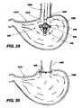
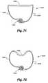
- FIG. 29is a schematic view showing the implant of FIG. 12 anatomically positioned at the gastroesophageal opening with the implant in a fully expanded state.
- FIG. 30is a schematic view showing the implant of FIG. 29 implanted to reduce the circumference of the gastroesophageal opening.
- FIG. 33is a plan view of a second embodiment of a drawstring implant in its normal state.
- FIG. 34is a plan view of a third embodiment of a drawstring implant in its normal state.
- FIG. 36is a plan view of a fifth embodiment of a drawstring implant in its normal state.
- FIG. 37is a plan view of a sixth embodiment of a drawstring implant in its normal state.
- FIG. 39is a plan view of an eighth embodiment of a drawstring implant in its normal state.
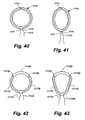
- FIG. 42is a schematic view of a variation on the drawstring implant of FIG. 31 showing the drawstring and internal attachment locations.
- FIG. 43is a schematic view of the drawstring implant of FIG. 42 in a cinched state.
- FIG. 45is a schematic view of the drawstring implant of FIG. 44 in a cinched state.
- FIG. 46is a schematic view of a variation on the drawstring implant of FIG. 34 showing the drawstring and internal attachment locations.
- FIG. 47is a schematic view of the drawstring implant of FIG. 46 in a cinched state.
- FIG. 49is a schematic view of the drawstring implant of FIG. 48 depicting the implant in its cinched state.
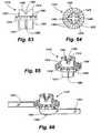
- FIG. 52is a schematic view of a third embodiment of a drawstring implant comprising internal shaping members depicting the implant in its normal state.
- FIG. 53is a schematic view of the drawstring implant of FIG. 52 depicting the implant in its cinched state.
- FIG. 54is a schematic view of a fourth embodiment of a drawstring implant comprising internal shaping members depicting the implant in its normal state.
- FIG. 55is a schematic view of the drawstring implant of FIG. 54 depicting the implant in its cinched state.
- FIG. 56is an isometric view of an implant and associated apparatus for adjusting the circumference of the implant from a remote location.
- FIG. 57is an isometric view of the implant of FIG. 56 .
- FIG. 58is an isometric view of the implant of FIG. 56 partially cut away to reveal interior detail.
- FIG. 59is an isometric view of the implant of FIG. 56 in a cinched condition.
- FIG. 60is a partial isometric view of a drive shaft of the apparatus of FIG. 56 for adjusting the circumference of an implant.
- FIG. 61is a partial isometric view of an inner tube of the apparatus of FIG. 56 for adjusting the circumference of an implant.
- FIG. 62is a partial isometric view of the drive shaft of FIG. 60 telescopically received within the inner tube of FIG. 61 .
- FIG. 63is a side view of a spindle of a winch of the implant of FIG. 56 .
- FIG. 64is a top view of the spindle of FIG. 63 .
- FIG. 65is an isometric view of the spindle of FIG. 63 .
- FIG. 66is an isometric view of the spindle of FIG. 63 showing a section of a band of the implant wrapped around the spindle.
- FIG. 67is an exploded isometric view of the implant of FIG. 56 .
- FIG. 68is an isometric view of the winch and band of the implant of FIG. 56 .
- FIG. 69is a side cut away view of the drive unit of the apparatus positioned to engage the winch of the implant of FIG. 56
- FIG. 70is a side cut away view of the drive unit and winch FIG. 69 depicting the drive unit engaged with the winch.
- FIG. 71is a top view of a second embodiment of a winch-adjustable implant.
- FIG. 72is a top view of a third embodiment of a winch-adjustable implant.
- FIG. 73is an isometric view of an alternate embodiment of a drive unit for rotating the winch on a winch-adjustable implant.
- FIG. 74is a side view of the drive shaft of the drive unit of FIG. 73 .
- FIG. 75is a bottom view of the drive shaft of FIG. 74 .
- FIG. 76is a side view of the actuator button of the drive unit of FIG. 73 .
- FIG. 77is a bottom view of the actuator button of FIG. 76 .
- FIG. 78is a side view of the inner cam sleeve of the drive unit of FIG. 73 .
- FIG. 80is a side view of the outer cam sleeve of the drive unit of FIG. 73 .
- FIG. 81is a bottom view of the outer cam sleeve of FIG. 80 .
- FIG. 82is an exploded view of the drive unit of FIG. 73 .
- FIG. 83is a side view of the drive unit of FIG. 73 showing the actuator button in its normal position.
- FIG. 84is a side view of the drive unit of FIG. 83 showing the actuator button in its depressed condition.
- FIGS. 85-89illustrate various embodiments of the present invention with the deployment of anchoring clips for affixing the implant to the tissue.
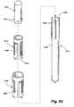
- FIG. 90is a perspective view of an alternate embodiment of an implant according to the present invention showing the implant attached to an inverted delivery umbrella protruding from a coaxial cannula.
- FIG. 91is a perspective view of the implant of FIG. 90 showing the outer cannula extended to cover the implant.
- FIG. 92is a perspective view of the implant of FIG. 90 showing the outer cannula retracted to expose the implant.
- FIG. 93is a perspective view of the implant of FIG. 90 showing the middle cannula extended to unfold the implant.
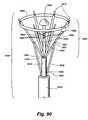
- FIG. 94is a schematic view illustrating the delivery apparatus in its closed configuration.
- FIG. 95is a schematic view illustrating the delivery apparatus in its open configuration.
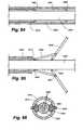
- FIG. 96is a cross sectional view of the delivery apparatus.
- FIG. 97is a perspective view of the lower end of a touchdown sensor of the implant of FIG. 90 , showing the sensor in an uncompressed condition.
- FIG. 98is a perspective view of the lower end of the touchdown sensor of FIG. 97 , showing the sensor in a compressed condition.
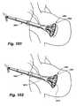
- FIG. 99is a perspective view of a procedure for the trans-atrial placement of the implant of FIG. 85 into the left atrium of a beating heart, where the implant is shown being introduced within a closed coaxial cannula placed through an incision or trocar wound controlled by a purse string suture.
- FIG. 100is a perspective view of a subsequent step of the procedure of FIG. 99 , where the outer cannula covering the implant is shown being retracted to partially expose the folded implant.
- FIG. 101is a perspective view of a subsequent step of the procedure of FIG. 99 , where the outer cannula is shown in a fully retracted position and with extension of the inverted delivery umbrella, fully unfolding the implant, and with touchdown sensors in an undepressed state.
- FIG. 102is a perspective view of a subsequent step of the procedure of FIG. 99 , where the outer cannula is shown in a fully retracted position and with extension of the inverted delivery umbrella, fully unfolding the implant, and with all touchdown sensors in an compressed state, indicating placement over the mitral annulus.
- FIG. 103is a perspective view of a subsequent step of the procedure of FIG. 99 , where a control suture has been cut and withdrawn from the implant, causing deployment of the anchoring clips therein within the anryulus of the valve.
- FIG. 104is a perspective view of a subsequent step of the procedure of FIG. 99 , where the inverted delivery umbrella has been detached from the implant and is retracted into the outer cannula for removal from the heart.
- FIG. 105is a perspective view of a subsequent step of the procedure of FIG. 99 , where the inverted delivery umbrella has been removed from the heart, leaving an adjustment element for adjustment of the implant's size and effect.
- FIG. 106is a perspective view of a subsequent step of the procedure of FIG. 99 , where adjustment of the implant's size and physiologic effect has been accomplished, and the remaining adjustment element is ready to be removed.
- FIG. 107is a schematic view of an alternate embodiment of a delivery apparatus.
- FIG. 108is a schematic view of a portion of the vascular system of a human body showing two possible entry points for percutaneous implantation of an apparatus for treating mitral valve regurgitation.
- FIG. 109is a schematic view of the human heart showing the mitral annulus and an entry wound in the left atrium.
- FIG. 110is a schematic view of the heart of FIG. 109 showing a delivery device entering the heart through the right internal jugular vein traversing the left atrium through the entry wound, and positioning the implant around the mitral annulus.
- FIG. 111is a schematic view of the heart of FIG. 109 showing a delivery device entering the heart through the right femoral vein, traversing the left atrium through the entry hound, and positioning the implant around the mitral annulus.
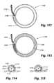
- FIG. 112is a top view of an implant for controlling the circumference of an internal orifice or lumen, wherein the implant comprises a spiral coil affixation device.
- FIG. 113is a bottom view of the implant of FIG. 112 .
- FIG. 114is a transverse cross section of the implant of FIG. 112 prior to the spiral coil affixation device being inserted through the underlying tissue.
- FIG. 115is a transverse cross section of the implant of FIG. 112 subsequent to the spiral coil affixation device being inserted through the underlying tissue.
- FIG. 116is a schematic view illustrating the actuation of a spiral coil affixation device of an alternate embodiment.
- FIG. 117is a schematic view of an alternate embodiment of an implantation device in which a coil attachment according to the present invention is used to attach an adjustable mitral annuloplasty implant in a minimally-invasive approach to a beating heart
- an exemplary implant 10comprising an implant body 15 is shown in FIG. 1 .
- the implant body 10may be provided in a shape and size determined by the anatomic needs of an intended native recipient anatomic site within—a mammalian patient.
- a native recipient anatomic sitemay be, by way of illustration and not by way of limitation, a heart valve, the esophagus near the gastro-esophageal junction, the anus, or other anatomic sites within a mammalian body that are creating dysfunction that might be relieved by an implant capable of changing the size and shape of that site and maintaining a desired size and shape after surgery.
- the implantcan be used for positioning an aortic valve, a triple A device positioning, aortic stent grafting applications, aortic endograph applications, aortic triple A stent graphs, ascending aortic aneurysm repair, for stomach applications to control obesity and the like.
- the implant 10 of FIG. Icomprises a circular implant body 15 which is provided with adjustable corrugated sections 20 alternating with intervening grommet-like attachment means 25 having narrowed intermediate neck portions.
- the implant body 15may be secured to the annulus of a heart valve 30 by a fixation means such as a suture 35 secured over or through the attachment means 25 .
- the corrugated sections 20fold and unfold as the circumference of the implant body 15 shortens or lengthens. Adjustment of the implant 10 in situ may decrease the overall size of the heart valve 30 , increasing the coaptation of the valve leaflets 40 , and changing the configuration from that shown in FIG. 2 to that shown in FIG. 3 .
- FIGS. 4 and 5An additional exemplary embodiment 100 of the present invention is shown in FIGS. 4 and 5 , with an open operative cardiac incision 105 in a heart 110 shown in FIG. 4 , and closure of the cardiac incision 105 in FIG. 5 .
- the exemplary adjustable implant 100according to the present invention comprises an implant body 115 with attachment means 120 that allows fixation to the annulus of a mitral valve 125 .
- the exemplary adjustable implant 100is further provided with an adjustment means 130 that is controlled boy an attached or coupled adjustment tool 135 . After closure of the myocardial incision 105 in FIG.
- the adjustment tool 135remains attached or coupled to the adjustment means 130 , so that the size and shape of the implant 100 may further be affected after physiologic flow through the heart 110 is resumed, but with the chest incision still open. Once the desired shape and function are achieved, the adjustment tool 135 may be disengaged from the adjustment means 130 and withdrawn from the myocardial incision 105 .
- the adjustment means 130may be configured and placed to allow retention by or re-introduction of the adjustment tool 135 for adjustment following closure of the chest incision.
- the physicianmakes the open operative incision 105 in the heart 110 , as shown in FIG. 4 , in the conventional manner.
- the implant 100mounted at the forward end of adjustment tool 135 , is then advanced through the incision 105 and sutured to the annulus of the mitral valve 125 .
- the adjustment tool 135is then manipulated, e.g., rotated, depending upon the design of the adjustment means 130 , to cause the adjustment means to reduce the size of the implant body 115 , and hence the underlying mitral valve 125 to which it is sutured, to an approximate size.
- the myocardial incision 105can now be closed, as shown in FIG. 5 , leaving the adjustment tool extending through the incision for post-operative adjustment.
- FIGS. 6-8show an exemplary adjustment means 200 for adjusting the circumference of an annular implant such as the implant 100 previously described.
- the adjustment means 200comprises a rack and pinion system in which a first cam 205 with geared teeth 210 and an engagement coupler 215 turns on a first axel 220 .
- the first cam 205engages a geared rack 225 on one or more surfaces of a first band 230 .
- the first band 230passes between the first cam 205 and a second cam 235 that turns on a second axel 240 that is joined to a second band 245 .
- the first and second axels 220 , 240are maintained in suitable spaced-apart relation by means of a bracket 250 formed at the end of the second band 245 .
- the adjustment means 200is preferably set within a hollow annular implant 100 of the type previously described, though it is possible to use the adjustment means in a stand-alone configuration wherein the first and second bands 230 , 245 are opposing ends of the same continuous annular structure.
- a toolsuch as a hex wrench engages the engagement coupler 215 on the first cam 205 and rotates the first cam in a counterclockwise direction as shown in FIG. 7 , as indicated by the arrow 255 .
- Rotation of the first cam 205causes' the teeth 210 to drive the rack 225 to move the first band 230 toward the right, as indicated by the arrow 260 in FIG. 7 .
- This movement of the first bandtightens the circumference of the annular implant. If the physician inadvertently adjusts the implant too tight, reversing direction of the engagement coupler 215 will loosen the implant.
- the first and second bands 230 , 245may be separate structures, or they may be opposing ends of the same continuous structure.
- the first cam 205is rotated, causing the geared teeth 210 to engage the geared rack 225 , and causing the first band 239 to move with respect to the second band 245 to adjust the circumference of an implant.
- FIG. 9shows a somewhat different configuration of an exemplary engagement means 300 according to the present invention, in which there is no engagement coupler, and a bracket 350 is provided on both sides of the cams to maintain the first cam 315 and the second cam 320 in close approximation.
- the bracketis designed with close tolerances so as to press the first band 330 closely against the second band 345 , thereby to hold the bands in fixed relative position by friction.
- the brackets 350are fabricated from an elastic material such that the cams 315 , 320 can be spread apart to insert the first band 330 between the cams, whereupon the cams are pulled back together with sufficient force to hold the bands 330 , 345 in fixed relative position by friction.
- FIG. 10shows an exemplary attachment means 400 for an implant according to the present invention.
- the attachment means 400could be used, for example, in place of the attachment means 25 of the implant 10 .
- the attachment means 400takes the form of a grommet 410 comprising a wall 415 defining a lumen 420 and an attachment surface 425 .
- Such an attachment meanswould be used with the implant body extending through the lumen 420 and with fixation devices such as sutures or wires either tied over or affixed through the attachment surface 425 .
- FIG. 11shows another alternate embodiment of an attachment means 500 for an implant according to the present invention.
- the attachment means 500could also be used, for example, in place of the attachment means 25 of the implant 10 .
- FIG. 11shows an attachment means 500 in the form of a hollow tube or tube segment 510 comprising a wall 515 defining a lumen 520 , an outer surface 525 , and an attachment tab 530 .
- fixation devicessuch as sutures or wires either tied or otherwise affixed over or through the attachment tab 530 .
- fixation devicesmight be placed through holes 535 provided in the attachment tab 530 .
- a solid attachment tab 530might be provided, and the fixation devices might be passed through the solid tab. Modifications of these attachment means may be used in conjunction with a sutureless attachment system.
- FIGS. 12-18show another embodiment of a percutaneous annuloplasty device according to the present invention, in which an implant/delivery system array 600 includes a housing sheath 605 (not seen in FIG. 12 ), an actuating catheter 610 coaxially slidably mounted within the housing sheath 605 , and a core catheter 615 coaxially slidably mounted within the actuating catheter 610 .
- the core catheterhas a central lumen 616 ( FIG. 13 ).
- the actuating catheter 610 and core catheter 615may be round tubular structures, or as shown in FIG.
- either or both of the actuating and core cathetersmay be provided with one or more keyed ridges 618 , 620 respectively to be received by one or more reciprocal slots 622 , 624 within the inner lumen of either the housing sheath 665 or the actuating catheter 610 , respectively.
- Such keyed ridges 618 , 620would limit internal rotation of an inner element within an outer element, should such restriction be desirable to maintain control of the inner contents from inadvertent displacement due to undesired rotational motion during use.
- the implant/delivery system array 600includes a distal tip 625 at the forward end of the core catheter 615 .
- One or more radial implant support arms 630have their distal ends 632 pivotably or bendably mounted to the core catheter 615 adjacent its distal tip 625 .
- the proximal ends 634 of the radial implant support arms 630normally extend along the core catheter 615 but are capable of being displaced outward away from the core catheter.
- One or more radial support struts 636have their proximal ends 638 pivotably or bendably mounted to the distal end of the actuating catheter 610 .
- the distal end 640 of each radial support strutis 636 pivotably or bendably attached to a midpoint of a corresponding radial implant support arm 630 .
- the radial support struts 636force the radial implant support arms 630 upward and outward in the fashion of an umbrella frame.
- the actuating catheter 610 , core catheter 615 , radial support struts 636 , and radial support arms 630in combination form a deployment umbrella 642 .
- a prosthetic implant 645is releasably attached to the proximal ends 634 of the radial implant support arms 630 .
- one or more of the radial implant support arms 630comprise touchdown sensors 648 whose proximal ends extend proximal to the implant 645 . Extending through the central lumen 616 ( FIG. 13 ) of the core catheter 615 in the exemplary embodiment 600 and out lateral ports 650 ( FIG.
- release elements 660spaced proximally from the distal tip 625 are one or more release elements 660 , which serve to release the implant 645 from the delivery system, and one or more adjustment elements 665 which serve to adjust the implant's deployed size and effect. Because the release elements 660 and adjustment elements 665 extend through the proximal end of the core catheter 615 , as seen in FIGS. 14-16 , these elements can be directly or indirectly instrumented or manipulated by the physician.
- a delivery interface 670(FIGS. 12 , 16 ) is defined in this example by the interaction of the deployment umbrella 642 , the release elements 660 , and the implant 645 .
- the release elements 660may be a suture, fiber, or wire in a continuous loop that passes through laser drilled bores in the implant 645 and in the radial implant support arms 630 , and then passes through the length of the core catheter 615 .
- the implant 645may be released from the delivery system at a desired time by severing the release element 660 at its proximal end, outside the patient, and then withdrawing the free end of the release element 660 through the core catheter 610 .
- FIGS. 14-16show the operation of the implant/delivery system array 600 , in which an umbrella-like expansion of the prosthetic implant 645 is achieved by sliding movement of the housing sheath 605 , the actuating catheter 610 , and the core catheter 615 .
- the housing sheath 605is extended to cover the forward ends of the actuating catheter 610 and core catheter 615 for intravascular insertion of the implant/delivery system array 600 .
- the housing sheath 605is retracted in the direction indicated by the arrows 662 .
- FIG. 15the housing sheath 605 has been retracted to expose the forward end of the actuating catheter 610 and the collapsed deployment umbrella 642 .
- FIG. 16shows the expansion of the deployment umbrella 642 produced by distal motion of the actuating catheter 610 relative to the core catheter 615 .
- FIGS. 17 and 18are schematic views illustrating the radial implant support arms 630 and the radial support struts 636 of the implant/delivery system array 600 .
- a radial support strut 636is pivotably attached at its proximal end 638 at a first pivotable joint 670 to the actuation catheter 610 .
- the radial support strut 636is attached at its distal end 640 to a second pivotable joint 672 at an intermediate point of a corresponding radial implant support arm 630 .
- the radial implant support arm 630is attached at its distal end 632 by a third pivotable joint 674 to the core catheter 620 .
- FIG. 17shows the assembly in a closed state.
- FIGS. 19 and 20show further details of the touchdown sensors 648 shown previously in FIG. 12 .
- the touchdown sensor 648 of FIGS. 19 and 20includes a distal segment 680 , an intermediate segment 682 , and a proximal segment 684 .
- the distal segment 680is spring-mounted, so that it is capable of slidable, telescoping displacement over the intermediate segment 682 to achieve a seamless junction with the proximal segment 684 upon maximal displacement.
- the springextends the proximal segment such that the sensor assumes the orientation shown in FIG. 19 .
- the implant 645FIG.
- the proximal segment 684 of the sensor 648is compressed against the distal segment 680 , as shown in FIG. 20 .
- the distal segment 680 and the proximal segment 684are both constructed of, are sheathed by, or otherwise covered with a radio-opaque material.
- the intermediate segment 682is not constructed or coated with such a radio-opaque material. Therefore, when the distal segment 680 is at rest, it is fully extended from the proximal segment 684 , and the gap represented by the exposed intermediate segment 682 is visible on radiographic examination.
- the touchdown sensoris said to be “activated”.
- This embodimentallows radiographic monitoring of the position of the touchdown sensor 648 with respect to the degree of extension of the distal catheter segment 680 .
- one or more touchdown detectors 648are employed to ascertain that the delivery system for the prosthetic device is located in the proper position to deploy the implant into the mitral annulus. As this anatomic structure cannot be directly identified on fluoroscopy or standard radiographic procedures, such precise location could be otherwise difficult. At the same time, precise localization and engagement of the mitral annulus is critical for proper implant function and safety.
- Touchdown detectors within the embodiments according to the present inventioncan have a multiplicity of forms, including the telescoping, spring-loaded, radio-opaque elements joined by a non-radio-opaque element as in the aforementioned examples.
- touchdown detectors according to the present inventionmay utilize metallic segments interposed by nonmetallic segments in a similar telescoping, spring-loaded array.
- Other embodimentsinclude a visually-evident system with telescoping, spring-loaded elements with color-coded or other visual features for procedures in which direct or endoscopic observation would be possible.
- touchdown detectorsinclude touchdown detectors provided with microswitches at their tips, such that momentary contact of sufficient pressure completes an electrical circuit and signals the activation of the touchdown detector to the operator.
- Still other touchdown detectors according to the present inventionare provided with fiberoptic pathways for compassion laser spectroscopy or other spectral analytical techniques which are capable of detecting unique tissue qualities of the tissue at the desired site for implantation.
- still other embodiments according to the present inventioninclude touchdown detectors containing electrodes or other electronic sensors capable of detecting and signaling the operator when a desired electrophysiologic, impedance, or other measurable quality of the desired tissue is detected for proper implantation.
- Such electrophysiologic touchdown detectorsmay include electrical circuits that produce visual, auditory, or other signals to the operator that the detectors are activated and that the implant is in the proper position for attachment.
- intracardiac or extracardiac imaging techniquesincluding, but not limited to, intravascular ultrasound, nuclear magnetic resonance, virtual anatomic positioning systems, or other imaging techniques may be employed to confirm proper positioning of the implant, obviating the need for the touchdown sensors as previously described.
- FIGS. 21-24show an implant 700 according to one embodiment of the present invention.
- the implant body 705is bandlike and flexible. Through much of its length, the implant body 705 is provided with a series of retention barbs 710 which are oriented to facilitate placement, retention, and removal of the device.
- the implant body 705is also provided with an adjustable section 715 , which is provided in this example with a series of adjustment stops 720 .
- the adjustment stops 720may be slots, holes, detents, dimples, ridges, teeth, raised elements, or other mechanical features to allow measured adjustment of the implant 700 in use. In the embodiment shown in FIGS. 21-24 , the adjustment stops 720 are engaged by a geared connector 725 .
- FIG. 21is an end view, showing the implant body 705 curved on itself, with the retention barbs 710 to the exterior, and with the adjustable section 715 passing through its engagement with the geared connector 725 and curving internally within the implant body 705 to form a closed, round structure.
- FIG. 23shows details of an exemplary geared connector 725 , in which a housing 730 is connected to the implant body 705 .
- the housing 730contains and supports a mechanical worm 740 with an attached first geared head 750 which mates with a second geared head 755 .
- the second geared head 755is attached to an adjustment stem 760 which is machined to receive a screwdriver-like adjustment element.
- the various embodiments according to the present inventionmay require a number of forms of adjustment elements.
- the adjustment elementis provided as a finely coiled wire with a distal tip machined to be received by a receiving slot in the adjustment stem 760 (not shown).
- the relationship between the distal tip of the adjustment element and the adjustment stem 760is mechanically similar to a screwdriver bit and screwhead, such that torsion imparted to the adjustment means by the operator will result in the turning of the adjustment stem 760 and second geared bead 755 allows motion of the first geared head 750 and worm 740 , which creates motion of the adjustable implant section 715 as the worm engages with the series of adjustment tops 725 . Excess length of the adjustable section 715 passes though a band slot 735 ( FIG.
- the adjustment element in this embodimentmay be designed to remain in place after the deployment umbrella has been retracted and withdrawn.
- the connection between the adjustment element's distal tip and the adjustment stem 760may be a simple friction connection, a mechanical key/slot formation, or may be magnetically or electronically maintained.
- the exemplary embodimentemploys unidirectional retention barbs 710 which are attached to the outer perimeter of the implant body 705 .
- the retention barbs 710are oriented in a consistent, tangential position with respect to the implant body 705 such that rotational motion of the implant body will either engage or release the retention barbs 710 upon contact with the desired tissue at the time of deployment.
- This positioning of the retention barbs 710allows the operator to “screw in” the implant 700 by turning the implant 700 upon its axis, thus engaging the retention barbs 710 into the adjacent tissue. As shown in FIG.
- the retention barbs 710may each be further provided with a terminal book 775 at the end which would allow for smooth passage through tissue when engaging the retention barbs 710 by rotating the implant 700 , without permitting the implant 700 to rotate in the opposite direction, because of the action of the terminal books 775 grasping the surrounding tissue (much like barbed fish books).
- the terminal books 775thus ensure the seating of the implant 700 into the surrounding tissue.
- FIGS. 25-27illustrate another embodiment of an implant 800 as contemplated according to the present invention.
- the implant 800includes a band 805 ( FIG. 27 ), but the retention barbs of the previous example have been eliminated in favor of an outer fabric implant sheath 810 .
- the fabric sheath 810can be sutured or otherwise affixed to the anatomic tissue in a desired location.
- the circumference of the implant body 800is adjusted through a geared connector 825 similar to the geared connector of the bandlike implant array shown in FIG. 23 . More specifically, adjustment stops 820 on the band are engaged by a mechanical worm 840 with an attached first geared bead 850 .
- the first geared head 850mates with a second geared head 855 .
- the second geared bead 855is attached to an adjustment stem 860 which is machined to receive a screwdriver-like adjustment element.
- FIG. 28illustrates an example of the method of use of an implant/delivery system array 600 for positioning an implant 645 in a patient with ischemic annular dilatation and mitral regurgitation.
- Peripheral arterial accessis obtained via conventional cutdown, arterial puncture, or other standard access techniques.
- guidewire placementis per-formed and intravascular access to the heart, 900 is obtained using fluoroscopic, ultrasound, three-dimension ultrasound, magnetic resonance, or other real-time imaging techniques.
- the guidewire, deployment device, and implantare passed through the aortic valve in a retrograde fashion into the left ventricle 905 and then into the left atrium 910 .
- the operatorretracts the housing sheath 605 , thus unsheathing the collapsed deployment umbrella 642 and implant 645 .
- the deployment umbrella 642is then distended by the distal motion of the actuation catheter, causing the radial support arms and struts to fully distend.
- the touchdown detectors 648are not in contact with any solid structures, and are fully extended with their radiolucent gaps visible on the imaging system. Once the deployment umbrella is distended, the entire assembly is pulled back against the area of the mitral valve 915 . At least two touchdown detectors 648 are employed in a preferred embodiment according to the present invention.
- the deployment umbrellaWhen all touchdown detectors show the disappearance of their intermediate, non-opaque, intermediate segments and are thus activated, then the deployment umbrella must be in contact with the solid tissue in the region of the mitral annulus/atrial tissue, and further implant deployment and adjustment may proceed. However, if any one touchdown sensor is not activated, and a radiolucent gap persists, then the device is not properly positioned, and must be repositioned before further deployment. Thus, the touchdown sensor system may assist in the deployment and adjustment of prosthetic devices by the delivery system according to the present invention. Once properly positioned, the operator rotates the actuation catheter in a prescribed clockwise or counterclockwise manner to engage the retention barbs on the implant into the tissue in the region of the mitral annulus/atrial tissue.
- the adjustment element(s)are operated to achieve the desired degree of annular reduction.
- Real-time trans esophageal echocardiography, intravascular echocardiography, intracardiac echocardiography, or other modalities for assessing mitral functionmay then be employed to assess the physiologic effect of the repair on mitral function, and additional adjustments may be performed.
- the release elementsare activated to detach the implant from the deployment umbrella. The operator then retracts the actuation catheter and extends the housing sheath, collapsing the deployment umbrella, and covering the components for a smooth and atraumatic withdrawal of the device from the heart and vascular system.
- the adjustment elementsmay be left in position after the catheter components are withdrawn for further physiologic adjustment.
- a catheter-based adjustment elementsmay subsequently be re-inserted though a percutaneous or other route.
- Such an adjustment elementmay be steerably operable by the operator, and may be provided with magnetic, electronic, electromagnetic, or laser-guided systems to allow docking of the adjustment element with the adjustable mechanism contained within the implant.
- the adjustment mechanismmay be driven by implanted electromechanical motors or other systems, which may be remotely controlled by electronic flux or other remote transcutaneous or percutaneous methods.
- initial catheter accessis achieved through a peripheral or central vein.
- Access to the pulmonary valveis also achieved from below the valve once central venous access is achieved by traversing the right atrium, the tricuspid valve, the right ventricle, and subsequently reaching the pulmonic valve.
- catheter access to the left atriumcan be achieved from cannulation of central or peripheral veins, thereby achieving access to the right atrium.
- a standard atrial trans-septal approachmay be utilized to access the left atrium by creation of an iatrogenic atrial septal defect (ASD).
- the mitral valvemay be accessed from above the valve, as opposed to the retrograde access described in Example 1.
- the implant and a reversed deployment umbrellamay be utilized with implant placement in the atrial aspect of the mitral annulus, with the same repair technique described previously.
- the iatrogenic ASDmay then be closed using standard device methods.
- Access to the aortic valvemay also be achieved from above the aortic valve via arterial access in a similar retrograde fashion.
- gastrointestinal disorderssuch as gastroesophageal reflux disease (GERD), a condition in which the gastro-esophageal (GE) junction lacks adequate sphincter tone to prevent the reflux of stomach contents into the esophagus, causing classic heartburn or acid reflux.
- GFDgastroesophageal reflux disease
- GEgastro-esophageal
- GEgastro-esophageal
- Thisnot only results in discomfort, but also may cause trauma to the lower esophagus over time that may lead to the development of pre-cancerous lesions (Barrett's esophagus) or adenocarcinoma of the esophagus at the GE junction.
- Surgical repair of the GE junctionhas historically been achieved with the Nissen Fundoplication, an operative procedure with, generally good results.
- an adjustable implantwould obviate the need for a hospital stay and be performed in a clinic or gastroenterologist's office.
- an umbrella deployment device 600 with implant 645is passed under guidance of an endoscope 1000 , through the patient's mouth, esophagus 1005 , and into the stomach 1010 , where the deployment device 600 is opened with expansion of the implant 645 and touchdown detectors 648 with a color-coded or otherwise visible gap.
- the touchdown detectorsare then engaged onto the stomach around the gastroesophageal junction 1015 under direct endoscopic control until all touchdown detectors 648 are visually activated.
- the implantis then attached to the stomach wall, 1020 the umbrella 642 is released and withdrawn, leaving behind the implant 645 and the adjustment elements.
- the implantis then adjusted until the desired effect is achieved, i.e., minimal acid reflux either by patient symptoms, pH monitoring of the esophagus, imaging studies, or other diagnostic means. If the patient should suffer from gas bloat, a common complication of gastroesophageal junction repair in which the repair is too tight and the patient is unable to belch, the implant can be loosened until a more desirable effect is achieved.
- the implant bodymay be straight, curved, circular, ovoid, polygonal, or some combination thereof.
- the implantmay be capable of providing a uniform or non-uniform adjustment of an orifice or lumen within the body.
- the implant bodymay further completely enclose the native recipient anatomic site, or it may be provided in an interrupted form that encloses only a portion of the native recipient anatomic site.
- the implant bodymay be a solid structure, while in yet other embodiments the implant body may form a tubular or otherwise hollow structure.
- the bodymay further be a structure with, an outer member, an inner member, and optional attachment members.
- the outer member of the implant bodymay serve as a covering for the implant, and is designed to facilitate and promote tissue ingrowth and biologic integration to the native recipient anatomic site.
- the outer member in such an embodimentmay be fabricated of a biologically compatible material, such as Dacron, PTFE, malleable metals, other biologically compatible materials or a combination of such biologically compatible materials in a molded, woven, or non-woven configuration.
- the outer member in such an embodimentalso serves to house the inner member.
- the inner memberprovides an adjustment means that, when operated by an adjustment mechanism, is capable of altering the shape and/or size of the outer member in a defined manner.
- the adjustment meansmay be located external to or incorporated within the outer member.
- the implant bodymay consist of an adjustment means without a separate outer member covering said adjustment means.
- the adjustment meansmay include a mechanism which may be threaded or nonthreaded, and which may be engaged by the action of a screw or worm screw, a friction mechanism, a friction-detent mechanism, a toothed mechanism, a ratchet mechanism, a rack and pinion mechanism, or such other devices to permit discreet adjustment and retention of desired size a desired position, once the proper size is determined.
- the adjustment meansmay comprise a snare or purse string-like mechanism in which a suture, a band, a wire or other fiber structure, braided or non-braided, monofilament or multifilament, is capable of affecting the anatomic and/or physiologic effects of the implant device on a native anatomic recipient site upon varying tension or motion imparted to said wire or fiber structure by a surgeon or other operator.
- Such an adjustment meansmay be provided as a circular or non-circular structure in various embodiments. Changes in tension or motion may change the size and/or shape of the implant.
- the adjustment meansmay be a metallic, plastic, synthetic, natural, biologic, or any other biologically-compatible material, or combination thereof. Such adjustment means may further be fabricated by extrusion or other molding techniques, machined, or woven. Furthermore, in various embodiments of the present invention, the adjustment means may be smooth or may include slots, beads, ridges, or any other smooth or textured surface.
- the implant bodymay be provided with one or more attachment members such as grommets or openings or other attachment members to facilitate attachment of the implant to the native recipient site.
- the implant bodymay attach to or incorporate a mechanical tissue interface system that allows a sutureless mechanical means of securing the implant at the native recipient site.
- sutures or other attachment meansmay be secured around or through the implant body to affix the implant body to the native recipient site.
- mechanical means of securing the implant body to the native recipient sitemay be augmented or replaced by use of fibrin or other biologically-compatible tissue gives or similar adhesives.
- the adjustable implantmay be employed to adjustably enlarge or maintain the circumference or other dimensions of an orifice, ostium, lumen, or anastomosis in which a disease process tends to narrow or constrict such circumference or other dimensions.
- an adjustment too]may be removably or permanently attached to the adjustment mechanism and disposed to impart motion to the adjustment mechanism and, in turn, to the adjustment means to increase or decrease the anatomic effect of the implant on the native recipient site.
- micromotor arrays with one or more micro-electromechanical motor systems with related electronic control circuitrymay be provided as an adjustment means, and may be activated by remote control through signals convey by electromagnetic radiation or by direct circuitry though electronic conduit leads which may be either permanently or removably attached to said micromotor arrays.
- the adjustment mechanismmay be provided with a locking mechanism disposed to maintain the position of the adjustment means in a selected position upon achievement of the optimally desired anatomic and/or physiologic effect upon the native recipient site and the bodily organ to which it belongs.
- no special locking mechanismmay be necessary due to the nature of the adjustment means employed.
- the adjustment means and/or the outer member structuremay be a pliable synthetic material capable of rigidification upon exposure to electromagnetic radiation of selected wavelength, such as ultraviolet light.
- exposure to the desired electromagnetic radiationmay be achieved by external delivery of such radiation to the implant by the surgeon, or by internal delivery of such radiation within an outer implant member using fiberoptic carriers placed within said outer member and connected to an appropriate external radiation source.
- fiberoptic carriersmay be disposed for their removal in whole or in part from the outer implant member after suitable radiation exposure and hardening of said adjustment means.
- the present inventionalso provides methods of using an adjustable implant device to selectively alter the anatomic structure and/or physiologic effects of tissues forming a passageway for blood, other bodily fluids, nutrient fluids, semi-solids, or solids, or wastes within a mammalian body.
- adjustable implantsinclude, but are not limited to, open surgical placement of said adjustable implants at the native recipient site through an open surgical incision, percutaneous or intravascular placement of said implants under visual control employing fluoroscopic, ultrasound, magnetic resonance imaging, or other imaging technologies, placement of said implants through tissue structural walls, such as the coronary sinus or esophageal walls, or methods employing some combination of the above techniques.
- adjustable implantsmay be placed and affixed in position in a native recipient anatomic site by trans-atrial, trans-ventricular, trans-arterial, trans-venous (i.e., via the pulmonary veins) or other routes during beating or non-beating cardiac surgical procedures or endoscopically or percutaneously in gastrointestinal surgery.
- alternate methods for use of an adjustable implant devicemay provide for the periodic, post-implantation adjustment of the size of the anatomic structure receiving said implant device as needed to accommodate growth of the native recipient site in a juvenile patient or other changes in the physiologic needs of the recipient patient.
- Adjustment of the adjustable implants and the methods for their use as disclosed hereincontemplates the use by the surgeon or operator of diagnostic tools to provide an assessment of the nature of adjustment needed to achieve a desired effect.
- diagnostic toolsinclude, but are not limited to, transesophageal echocardiography, echocardiography, diagnostic ultrasound, intravascular ultrasound, virtual anatomic positioning systems integrated with magnetic resonance, computerized tomographic, or other imaging technologies, endoscopy, mediastinoscopy, laparoscopy, thoracoscopy, radiography, fluoroscopy, magnetic resonance imaging, computerized tomographic imaging, intravascular flow sensors, thermal sensors or imaging, remote chemical or spectral analysis, or other imaging or quantitative or qualitative analytic systems.
- the implant/delivery system of the present inventioncomprises a collapsible, compressible, or distensible prosthetic implant and a delivery interface for such a prosthetic implant that is capable of delivering the prosthetic implant to a desired anatomic recipient site in a collapsed, compressed, or non-distended state, and then allowing controlled expansion or distension and physical attachment of such a prosthetic implant by a user at the desired anatomic recipient site.
- Such a systempermits the delivery system and prosthetic implant to be introduced percutaneously through a trocar, sheath, via Seldinger technique, needle, or endoscopically through a natural bodily orifice, body cavity, or region and maneuvered by the surgeon or operator to the desired anatomic recipient site, where the delivery system and prosthetic implant may be operably expanded for deployment.
- the implant/delivery system according to the present inventionis also capable of allowing the user to further adjust the size or shape of the prosthetic implant once it has been attached to the desired anatomic recipient site.
- the delivery system according to the present inventionis then capable of detaching from its interface with the prosthetic implant and being removed from the anatomic site by the operator.
- the delivery system and prosthetic implantmay be provided in a shape and size determined by the anatomic needs of an intended native recipient anatomic site within a mammalian patient.
- a native recipient anatomic sitemay be a heart valve, the esophagus near the gastro-esophageal junction, the anus, or other anatomic sites within a mammalian body that are creating dysfunction that might be relieved by an implant capable of changing the size and shape of that site and maintaining a desired size and shape after surgery.
- the delivery systemmay be a catheter, wire, filament, rod, tube, endoscope, or other mechanism capable of reaching the desired recipient anatomic site through an incision, puncture, trocar, or through an anatomic passageway such as a vessel, orifice, or organ lumen, or trans-abdominally or trans-thoracically.
- the delivery systemmay be steerable by the operator.
- the delivery systemmay further have a delivery interface that would retain and convey a prosthetic implant to the desired recipient anatomic site.
- Such a delivery interfacemay be operably capable of distending, reshaping, or allowing the independent distension or expansion of such a prosthetic implant at the desired recipient anatomic site.
- such a delivery interfacemay provide an operable means to adjust the distended or expanded size, shape, or physiologic effect of the prosthetic implant once said implant has been attached in situ at the desired recipient anatomic site.
- such adjustmentmay be carried out during the procedure in which the implant is placed, or at a subsequent time.
- the delivery interface and the associated prosthetic implantmay be straight, curved, circular, helical, tubular, ovoid, polygonal, or some combination thereof.
- the prosthetic implantmay be a solid structure, while in yet other embodiments the prosthetic implant may form a tubular, composite, or otherwise hollow structure.
- the prosthetic implantmay further be a structure with an outer member, an inner member, and optional attachment members.
- the outer member of the prosthetic implantmay serve as a covering for the implant, and is designed to facilitate and promote tissue ingrowth and biologic integration to the native recipient anatomic site.
- the outer member in such an embodimentmay be fabricated of a biologically compatible material, such as Dacron, PTFE, malleable metals, other biologically compatible materials or a combination of such biologically compatible materials in a molded, woven, or non-woven configuration.
- the outer member in such an embodimentalso serves to house the inner member.
- the inner memberprovides an adjustment means that, when operated by an adjustment mechanism, is capable of altering the shape and/or size of the outer member in a defined manner.
- At least some portions of the adjustable inner or outer membermay be elastic to provide an element of variable, artificial muscle tone to a valve, sphincter, orifice, or lumen in settings where such variability would be functionally valuable, such as in the treatment of rectal incontinence or vaginal prolapse.
- FIGS. 31-39illustrate various embodiments of a ring in its relaxed condition.
- FIG. 31illustrates a circular ring 1110 having drawstrings 1111 , 1112 extending from a lower portion thereof.
- FIG. 32illustrates an oval ring 130 having drawstrings 1121 , 1122 .
- FIG. 33depicts a hexagonal ring 1130 .
- FIG. 34illustrates a ring 1140 in the shape of a partial circle 1145 with a straight leg 1146 connecting the two ends of the partial circle.
- FIG. 35shows a ring 1150 comprising an arcuate portion 1154 and three-straight leg portions 1155 - 1157 connecting the two ends of the arc.
- FIG. 31illustrates a circular ring 1110 having drawstrings 1111 , 1112 extending from a lower portion thereof.
- FIG. 32illustrates an oval ring 130 having drawstrings 1121 , 1122 .
- FIG. 33depicts a hexagonal ring 1130 .
- FIG. 36shows a curvilinear ring 1160 having a convex portion 1164 on one side and a concave portion 1166 on the other.
- FIG. 37depicts a curvilinear ring 1170 which is concave on both sides 1174 , 1176 .
- FIG. 38illustrates a ring 1180 which is generally circular in shape and has an opening 1184 in its upper end.
- FIG. 39shows a ring comprising an arcuate portion 1194 and straight legs 1195 , 1196 extending toward one another but leaving an opening 1197 there between.
- FIGS. 40 and 41show the ring 1110 cut away to show the drawstrings 1111 , 1112 .
- the entire ring 10is adjusted smaller.
- drawstrings 1111 , 1112can be freely slidable within the ring 1110 , rather than anchored, with largely the same effect.
- the ring 1110 A of FIGS. 42 and 43is only partially adjustable.
- the ends of the drawstrings 1111 A, 1112 Ado not meet but rather are anchored at locations 1113 A, 1113 B around the ring 1110 A.
- the segments 1117 A, 1117 B through which the drawstrings extendare the sections which are most adjusted.
- the section 1118 A, through which no portion of either drawstring extendsreceives relatively little adjustment.
- FIGS. 44-47illustrate the effect of internal reinforcement on the adjustability of a ring.
- a ring 1140has no internal reinforcement. Consequently, when the drawstrings 1141 , 1142 are tensioned, the entire ring 1140 adjusts.
- the ring 1140 A of FIGS. 46 and 47has a reinforcing element 1144 A extending through the straight leg 1146 A of the ring.
- the reinforcing element 1144 Ais a hollow tube.
- the reinforcing element 1144 Acan assume other configurations, including a solid rod of suitable cross-section.
- the drawstrings 1141 A, 1142 Aare anchored to the ends of the reinforcing element 1144 A.
- the drawstringscan extend through the tube, either to be anchored at a common location inside the tube or to be freely slidable within the tube.
- the drawstringscan extend alongside the reinforcing element 1144 A, either to be anchored at a common location alongside the reinforcing element or to be freely slidable alongside the reinforcing element.
- FIGS. 48-51illustrate the use of internal shaping members operatively associated with the drawstrings such that when the drawstrings are tensioned, the shaping members cause the ring to assume a predetermined configuration.
- a generally circular ring 1200has a plurality of wedge-shaped shaping members 1201 disposed within the ring.
- the left drawstring 1202is connected to the right-most shaping number 1201 A
- the right drawstring 1203is connected to the left-most shaping number 1201 B when the drawstrings 1202 , 1203 are tensioned, the right-most shaping member 1201 A and the left-most shaping member 1201 B are drawn toward one another.
- This movement of the outermost shaping memberscauses the wedge surfaces of each shaping number 1201 to confront the wedge surfaces of the adjacent shaping members, forcing the group of shaping members to assume the concave configuration illustrated in FIG. 49 .
- shaping members 1201 of the embodiment of FIGS. 48 and 49are configured to assume a concave configuration when the drawstrings are cinched, it will be appreciated that the configuration of the shaping members may be designed such that the group forms a convex configuration, a straight line, a serpentine configuration with both convex and concave portions, or any other desired geometric shape.
- a generally circular ring 1210has two groups 1212 , 1213 of wedge-shaped shaping members 1211 .
- the ring 1210comprises four drawstrings, a pair of drawstrings being associated with each of the two groups 1212 , 1213 of wedge-shaped shaping members 1211 .
- the first drawstring 1214extends around the ring 1210 in a clockwise direction and is connected to the uppermost member 1211 A of the first group 1212 of shaping members 1211 .
- the second drawstring 1215extends around the ring 1210 in a counterclockwise direction and is connected to the lowermost member 1211 B of the first group 1212 of shaping members 1211 .
- the third drawstring 1216extends around the ring 1210 in a clockwise direction and is connected to the lowermost member 1211 C of the second group 1213 of shaping members 1211
- the fourth drawstring 1217extends around the ring in a counterclockwise direction and is connected to the uppermost member 1211 D of the second group 1213 of shaping members.
- the first group 1212 of shaping members 1211is drawn together, and the second group 1213 of shaping members is drawn together.
- the two groups 1212 , 1213 of members 1211assume predetermined geometric shapes, causing the ring 1210 to assume the ovoid configuration shown in FIG. 51 .
- the two groups of shaping members in the embodiment of FIGS. 50 and 51form identical geometric shapes, it will be understood that the configuration of the shaping members may be designed such that each group forms a different shape.
- the two groups of shaping members in the embodiment of FIGS. 50 and 51form convex geometric shapes, it will be appreciated that the shaping members can be configured to assume a concave shape, a straight line, or a serpentine shape comprising both convex and concave sections, or any combination of these and other shapes.
- FIGS. 31 through 51lie in essentially a single plane when in their relaxed state and further lie in essentially a single plane when the drawstrings are tensioned.
- FIGS. 52 through 55illustrate embodiments in which internal shaping members are configured to adjust the ring to a more three-dimensional shape.
- a ring 1220comprises a plurality of shaping members 1221 formed into two groups 1222 , 1223 . With the ring lying flat, the shaping members are narrower at the top than at the bottom. Thus, when the drawstrings 1224 - 1227 are cinched, the ring bows upward into the saddle-shaped configuration depicted in FIG. 53 .
- FIGS. 54 and 55illustrate an embodiment of a ring 1230 comprising a variety of differently configured shaping members 1231 . Only some of the shaping members 1231 are shown in FIGS. 54 and 55 for clarity of illustration.
- the shaping members 1231are arranged in alternating groups 1232 of shaping members narrower at the top than at the bottom and groups 1233 of shaping members narrower at the bottom than at the top. Utilizing the principles previously explained, it will be seen that, by having some shaping members narrower at the top that the bottom and some shaping members narrower at the bottom than at the top, complex three-dimensional configurations can be achieved.
- the ringscan be curvilinear ( FIGS. 31 , 32 , and 36 - 38 ), rectilinear ( FIG. 33 ), or a combination of straight and curved segments ( FIGS. 34 , 35 , and 39 ).
- the ringcan be either entirely closed ( FIGS. 31-37 ) or partially closed ( FIGS. 38 and 39 ).
- the ringscan be fully adjustable ( FIGS. 40 , 41 , 44 , and 45 ) or partially adjustable ( FIGS. 42 , 43 , 46 , and 47 ).
- the ringscan be unreinforced ( FIGS. 31-45 ) or reinforced ( FIGS. 46 and 47 ).
- the ringscan contain shaping members that assume a specific geometric configuration in two dimensions ( FIGS. 48-51 ) or three dimensions ( FIGS. 52-55 ).
- FIGS. 31-55all employ drawstrings as a means for adjusting the circumference of the implants.
- a different approachis taken in the embodiment of FIGS. 56-70 , in which an adjustable implant employs a winch to take up or to let out the circumference of the ring.
- a system 1300 for adjusting the configuration of a mitral valve annulusincludes an adjustable ring 1310 , a drive unit 1312 , and a winch 1314 (largely hidden within the lower end of the drive unit 1312 in FIG. 56 ). Each of these components will now be discussed in more detail.
- the ring 1310is at its maximum circumference and is coupled to the winch 1314 at each end.
- the ring 1310comprises an outer layer 1320 of Dacron.
- the ring 1310is cut away to reveal an intermediate layer 1322 and a band 1324 of nitinol or other suitable flexible, nonextensible material.
- FIG. 59shows the ring 1310 in a contracted state.
- FIG. 60illustrates the distal portion of a drive shaft 1330 of the drive unit 1310 .
- the drive shaft 1330is of indeterminate length but is advantageously long enough to extend to a location outside the patient, while at the same time being as short as possible to facilitate transmission of torque along the length of the shaft 1330 .
- the drive shaft 1330is preferably a solid, flexible rod of circular cross-section, but it will be understood that other suitable shapes, including hollow tubes, or rods of cross-section other than circular, can be employed.
- the drive shafthas a winch-engaging member 1332 at its distal end 1334 .
- the wench-engaging member 1332takes the form of a flat-blade screwdriver tip.
- other suitable tip configurationscan be used to cooperatively engage the wench 1314 , including, but not limited to, a Philips head tip, a hex head tip, a wrench socket, and the like.
- Spaced proximally up the drive shaft 1330 from the distal end 1334is a circumferential groove 1336 .
- FIG. 61depicts the distal portion of an inner tube 1340 of the drive unit 1310 .
- the inner tube at 1340is comprised of a flexible material.
- the inner tube 1340has a lumen 1342 slightly larger than the outer diameter of the drive shaft 1330 such that the drive shaft can rotate freely within the inner tube 1340 .
- a pair of openings 1346dimensioned to clear portions of the winch 1320 .
- a pair of axially-extending slots 1348are also at the distal end 1344 of the inner tube 1340 , which permit the distal end 1344 of the inner tube 1340 to expand slightly.
- a plurality of inwardly projecting protrusions 1350Spaced around the periphery of the lumen, 1342 just proximal of the distal end 1344 of the inner tube 1340 are a plurality of inwardly projecting protrusions 1350 .
- an inwardly extending annular ring 1352Just proximal of the proximal ends of the slots 1348 is an inwardly extending annular ring 1352 (not shown in FIG. 61 ; see FIGS. 69 , 70 ).
- FIG. 62shows the drive shaft 1330 disposed within the inner tube 1340 .
- the distal end of the drive shaft 1330is recessed within the distal end of the inner tube 1340 .
- the annular ring 1352 ( FIGS. 69 , 70 ) of the inner tube 1340engages the circumferential groove 1336 of the drive shaft 1330 to retain the drive shaft and inner tube in predetermined axial relation.
- the final component of the drive unit 1310is an outer tube 1360 ( FIGS. 69 , 70 ) of a flexible, resilient material.
- the outer rube 1360has a lumen dimensioned to receive the inner tube 1340 there within, for a purpose which will be explained herein below.
- FIGS. 63-65illustrate a spindle 1370 of the winch 1320 .
- the spindle 1370has an upper end 1372 , a lower end 1374 , and a disk 1376 intermediate the upper and lower ends.
- the upper end 1372 of the spindle 1370comprises a drive-shaft engagement means 1378 , which in the disclosed embodiment comprises a pair of transverse slots 1380 dimensioned to receive the flat-blade screwdriver tip 1332 of the drive shaft 1330 ( FIG. 60 ).
- the portions of the spindle 1370 between the slots 1380are beveled to form facets 1382 which direct the flat-blade screwdriver tip 1332 of the drive shaft into the slots.
- a generally cylindrically shaped body 1384is below the disk, but it will be understood that a solid cylindrical body is also suitable.
- slots 1386are formed to extend in a generally axial direction.
- the upper surface of the disk 1376comprises a plurality of recesses 1398 , the purpose of which will be explained below.
- FIG. 66shows a section of the band 1324 of the ring 1310 received within the slots 1386 and wrapped around the cylindrical body 1384 of the spindle 1370 .
- the winch 1312comprises a housing 1390 consisting of upper and lower housing halves 1390 A, 1390 B.
- the upper and lower housing halves 1390 A, 1390 Bare preferably formed with cooperating pins and holes to facilitate in aligning and mating the housing halves.
- a circular opening 1394is formed in the upper end 1392 of the upper housing half 1390 A.
- a plurality of teeth 1396Surrounding the circular opening 1394 and protruding downward from the inner surface of the upper housing half 1390 A are a plurality of teeth 1396 .
- the edges 1397 of the upper surface 1392are beveled.
- the upper and lower housing halves 1390 A, 1390 Beach comprise a generally cylindrical portion 1398 A, 1398 B and tangentially extending sleeve portions 1400 A, 1400 B.
- the outer periphery of the lower housing half 1390 Bhas a plurality of dimples 1402 formed therein. Seated within the lower housing half 1390 B is a wave spring 1404 . A washer 1406 with an annular recess 1408 formed in its upper surface sits atop the wave spring 1404 . A portion of the band 1324 of the ring 1310 is received within the slots 1386 in the lower end 1374 of the spindle 1370 , and the lower end 1374 of the spindle rests within the annular recess 1408 in the upper surface of the washer 1406 . Portions 1410 , 1412 of the band 1324 adjacent the spindle 1370 are seated within the tangentially extending-sleeve portions 1400 B of the lower housing half.
- the upper housing half 1390 Ais then assembled onto the lower housing half 1390 B.
- the upper end 1372 of the spindle 1370extends through the circular opening 1394 in the upper housing half 1390 A such that the drive-shaft engagement means 1378 resides outside the housing 1390 .
- the band 1324exits the housing 1390 through the tangentially extending sleeves 1400 such that the major portion of the band resides outside the winch housing.
- FIGS. 69 and 70illustrate the engagement of the drive unit 1312 with the winch 1314 .
- the winch 1314is in a self-locked state. This state is achieved by the wave spring 1404 urging the washer 1406 upward, which in turn forces the spindle 1370 upward against the top interior surface of the winch housing 1390 .
- the teeth 1396extending downward from the top interior surface of the housing engage the recesses 1386 in the upper surface of the disk 1376 of the spindle 1370 , preventing rotation of the spindle.
- the inner edges of the distal end 1344 of the inner tube 1340confront the beveled outer edges of the upper end 1392 of the housing 1390 and spread the distal end of the inner tube.
- the tangential sleeves 1400 ( FIG. 68 ) of the winch housing 1390are received within the openings 1346 ( FIG. 61 ) in the distal end 1344 of the inner tube 1340 .
- the inwardly projecting protrusions 1350 within the distal end 1344 of the inner tubeengage the dimples 1402 in the lower outer portion of the winch housing 1390 to lock the drive unit 1312 to the winch 1314 .
- the blade 1332 of the drive shaft 1330confronts the beveled facets 1382 and is directed into one of the slots 1380 .
- the spindle 1370is forced downward, flattening the wave spring 1404 and disengaging the recesses 1386 in the upper surface of the disk 1376 of the spindle from the teeth 1396 on the interior upper surface of the winch housing 1390 .
- the spindlecan now be turned.
- the band(not shown in FIGS. 69-70 ) wraps around the spindle 1370 as the drive shaft 1330 is turned, shortening the length of the band outside the winch housing 1390 .
- the drive unit 1312is disengaged from the winch 1314 .
- the outer tube 1360is advanced until it confronts the tangential sleeves 1400 ( FIG. 68 ) of the winch housing 1390 .
- the outer tube 1360is then used to hold the winch 1314 and ring 1310 in place while the inner tube 1340 is retracted.
- the protrusions 1350 within the distal end 1344 of the inner tubedisengage from the dimples 1 , 402 in the lower outer portion of the winch housing 1390 .
- the drive shaft 1330releases its downward pressure on the spindle 1370 .
- the wave spring 1404returns to its normal, uncompressed condition, biasing the spindle 1370 upward so that the teeth 1396 on the interior upper surface of the winch housing 1390 once again engage the cooperating recesses 1386 in the upper surface of the disk 1376 .
- the spindle 1370is now prevented from rotating, thereby locking the winch 1314 and fixing the exposed length of the ring 1310 .
- the use of the device 1300 to reconfigure a mitral valve annuluswill now be described.
- the heartis opened, and the ring 1310 is sutured around the mitral valve annulus, placing stitches through the fabric outer layer 1320 and the adjacent tissue.
- the drive unit 1312is coupled to the winch 1314 , and preliminary adjustment of the ring is effected.
- the heartis now closed, and the patient is taken off bypass.
- final adjustment of the ringcan be effected via the drive unit, checking for reflux by suitable medical visualization means.
- the drive unitis uncoupled from the winch and removed without having to once again place the patient on bypass.
- FIG. 71illustrates an alternate embodiment of a winch-adjustable ring 1410 which is D-shaped.
- the ring 1410is partially adjustable and consists of a combination of straight and curved sections.
- a band 1470is split, and a straight, relatively rigid section 1455 interconnects the free ends of the band.
- the band 1470is wound around the winch 1314 and is taken up and let out in the same manner described above.
- FIG. 72illustrates another alternate embodiment of a winch-adjustable ring 1510 which is partially adjustable and which is concave on one side.
- a band 1570is split, and a curved, relatively rigid section 1555 is connected between the free ends of the band.
- the band 1570is wound around the winch 1314 and is taken up and let out in the same manner described above.
- FIG. 73illustrates a drive unit 1600 for remotely rotating the winch 1314 of the rings 1310 , 1410 , and 1510 .
- the drive unit 1312previously described transmits rotational force exerted by the user to the winch
- the drive unit 1600converts axial movement of the user into rotational movement of the winch.
- the drive unit 1600includes a drive shaft 1610 , an actuator button 1612 , an inner cam sleeve 1614 , and an outer cam sleeve 616 .
- the drive unit 1600includes a drive shaft 1610 , an actuator button 1612 , an inner cam sleeve 1614 , and an outer cam sleeve 616 .
- the drive shaft 1610includes an elongated shaft member 1620 having an upper end 1622 and a lower end 1624 .
- a winch-engaging member 1626 in the form of a flat-head screwdriver bladeis formed at the lower end 1624 of the shaft 1620 .
- At the upper end 1622 of the shaft 1620a plurality of longitudinally extending ribs 1628 are formed. In the disclosed embodiment there are four ribs 1628 spaced equidistant around the perimeter of the shaft 1620 .
- the actuator button 1612has a rounded upper end 1630 and a lower end 1632 . Adjacent the lower end 1632 of the actuator button, a plurality of pins project radially outward.
- the pins 1634are preferably wider at their outer ends, tapering inwardly as the pins approach the body of the actuator button 1612 . In the disclosed embodiment there are four pins 1634 spaced equidistant around the periphery of the actuator button 1612 .
- a plurality of downwardly extending protrusions 1636are formed on the lower end 1632 of the actuator button 1612 .
- the protrusions 1636are slightly angularly offset with respect to the pins 1634 .
- FIGS. 78 and 79illustrate the inner cam sleeve 1614 .
- the inner cam sleeve 1614has an upper end 1640 , a lower end 1642 , and a vertical bore 1644 .
- the bore 1644is dimensioned to receive the upper end of the drive shaft 1610 and the lower end of the actuator button slidably there within.
- a plurality of generally vertical slots 1646are formed in the wall of the sleeve 1614 and extend through the lower end 1642 of the sleeve. In the disclosed embodiment there are four such slots 1646 formed at 90* intervals around the sleeve. Also at the lower end 1642 of the sleeve 1614 , a plurality of angled teeth 1648 are formed. In the disclosed embodiment, the teeth 1648 are generally vertical on the right side and slanted on the left side. There are eight such teeth 1648 in the disclosed embodiment, spaced equidistant around the perimeter of the sleeve 1614 .
- FIGS. 80 and 81illustrate the outer cam sleeve 1616 , which is similar in configuration to the inner cam sleeve 1614 except the teeth 1652 are angled in the opposite direction, that is, the left side of each tooth 1652 is generally vertical and the right side of each tooth 1652 is slanted.
- the bore 1654 of the outer cam sleeve 1616is dimensioned to receive the inner cam sleeve 1614 slidably there within.
- the outer cam sleeve 1616has a plurality of generally vertical slots 1656 formed in the wall of the sleeve at 90° intervals.
- the inner and outer cam sleeves 1614 , 1616are nested and rotated relative to one another so that the vertical slots 1646 , 1656 are aligned.
- the actuator button 1612is then inserted into the inner cam sleeve 1614 from the lower end 1642 , with the pins 1634 of the actuator button 1612 riding within the vertical slots 1646 , 1656 of the inner and outer cam sleeves 1614 , 1616 .
- the upper end 1622 of the drive shaft 1610is then inserted into the lower end 1642 of the inner cam sleeve 16142 with the ribs 1628 at the upper end 1622 of the shaft 1620 fitting within the vertical slots 1646 , 1656 of the inner and outer cam sleeves 1614 , 1616 .
- FIGS. 83 and 84Operation of the drive unit 1600 will now be explained with reference to FIGS. 83 and 84 , in which the outer cam sleeve 1616 has been removed for clarity of illustration.
- the actuator button 1612is in the “up” position.
- the pins 1634 of the actuator button 1612are located within the upper portions of the vertical slots 1646 of the inner cam sleeve 1614 .
- the drive shaftis in its upper or “retracted” position, with the ribs 1628 at the upper end 1622 of the shaft 1620 fitting within the vertical slots 1646 of the inner cam sleeve 1614 .
- the lower end 1632 of the actuator button 1612bears against the upper end 1622 of the drive shaft 1610 , forcing it downward.
- the protrusions 1636 ( FIGS. 76 and 77 ) on the lower end 1632 of the actuator button 1612bear against the upper ends of the ribs. However, since the protrusions are angularly offset, they tend to bias the ribs toward the left (as seen in FIGS. 82 and 83 ).
- the actuator button 1612is depressed sufficiently for the ribs 1628 at the upper end 1622 of the shaft 1620 to clear the lower end of the slots 1646 , the ribs are biased to the left.
- the actuator buttonis released, the drive shaft 1610 is biased upward by a spring.
- the upper ends of the ribs 1628engage the angled surface of the corresponding teeth 1648 and ride along the angled surface until confronting the vertical surface of the adjacent teeth.
- the effect of this interaction between the ribs 1628 at the upper end of the drive shaft 1610 and the slots 1646 and teeth 1648 at the lower end of the inner cam sleeve 1614is that the drive shaft is extended and rotated one-eight of a turn in the clockwise direction (as viewed from the upper end of the drive unit 1600 ).
- the extension of the drive shaft 1610depresses the spindle 1370 of the winch 1314 (similar to FIG. 70 ), disengaging the teeth 1396 in the roof of the winch housing 1390 from the recesses 1386 in the spindle.
- the spindle 1370is then rotated one-eighth of a turn in the clockwise direction, taking up the band 1324 .
- the inner cam sleeve 1614is advanced down the shaft 1610 until the teeth 1648 in the lower end of the inner cam sleeve clear the lower end of the outer cam sleeve 1616 .
- the actuator button 1612is depressed and released, the ribs 1628 interact with the lower end of the inner cam sleeve 1614 .
- the outer cam sleeve 1616is advanced with respect to the inner cam sleeve until the teeth 1652 clear the lower end of the inner cam sleeve 1614 .
- the actuator button 1612is depressed and released, the ribs 1628 interact with the lower end of the outer cam sleeve 1616 .
- the drive unit 1600makes possible the adjustment of an implant 1310 , 1410 , 1510 from a location spaced apart from the implant. This feature makes it possible to effect open-heart surgery to place the implant, close the heart, go “off pump,” restart the heart, and then adjust the circumference of the implant (and thereby the mitral valve annulus) while the heart is actually beating.
- an implant 1710comprises deployable anchoring clips for affixing the implant to the tissue surrounding an annulus whose circumference is desired to be adjusted.
- the implant 1710comprises a plurality of clips 1712 of nitinol or other resilient, shape memory material.
- the clipsmay be from approximately 4 mm to approximately 10 mm in length. In their retracted state as shown in FIG. 84 , the clips 1712 are straight and lie flush against (or possibly recessed within) the lower face 1714 of the implant 1710 .
- each clip 1712is anchored to the underlying implant by stitching, adhesive, heat fusion, eyelets, by being woven into the implant, or by other suitable means.
- the clips 1712When released from their retracted state, the clips 1712 assume their normal configuration as shown in FIG. 85 , that is, the free ends of the clips curve into overlapping barbs.
- FIGS. 86-89illustrate the deployment of the clips 1712 .
- the clips 1712are initially straight and lie flush against the underlying lower face 1714 of the implant 1710 .
- a deployment suture 1720extends upward through one free end of a first clip, along the clip, and then downward through the opposite free end of the first clip and into the underlying substrate.
- the suture 1720then extends upward through the first free end of a second clip, etc., until all clips are secured to lie flush against the bottom face of the implant 1710 .
- the deployment suture 1720is pulled. As the suture releases the first clip, the clip assumes its normal configuration of overlapping barbs, anchoring itself into the underlying tissue. As the suture is pulled further, the second clip is released, curling itself into overlapping barbs and anchoring itself into the underlying tissue. This procedure is continued until all clips are released and have anchored themselves into the underlying tissue.
- FIGS. 90 96show another embodiment of a minimally invasive annuloplasty device according to the present invention, in which an implant is housed in a coaxial catheter and inserted from a minimally invasive surgical entry through the left atrium to treat a dilated and regurgitant mitral valve.
- an implant/delivery system array 1800includes a housing sheath 1810 , an actuating catheter 1815 coaxially slidably disposed within the housing sheath 1810 , and a core catheter 1820 coaxially slidably located within the actuating catheter 1815 .
- the core catheter 1820has one or more central lumens 1822 (see FIG. 96 ).
- the actuating catheter 1815 and core catheter 1820may be separate structures as shown in FIG. 96 , or in alternate embodiments, the actuating and core catheters may be a combined or continuous structure.
- the implant/delivery system array 1800includes a distal tip 1825 at the forward end of the core catheter 1820 .
- One or more radial implant support arms 1830have distal ends 1835 and proximal ends 1840 .
- the proximal ends 1840 of the radial implant support arms 1830are pivotably or bendably mounted to the core catheter 1820 at a pivot point 1842 .
- the distal ends 1835 of the radial implant support arms 1830normally extend along the core catheter 1820 but are capable of being displaced outward away from the core catheter.
- One or more radial support struts 1845have proximal ends 1850 pivotably or bendably mounted to the distal end of the actuating catheter 1815 at a pivotable Joint 1852 .
- the distal end 1855 of each radial support strut 1845is pivotably or bendably attached to a pivotable joint 1857 at a midpoint of a corresponding radial implant support arm 1830 .
- the radial support struts 1845force the radial implant support an ns 1830 upward and outward in the fashion of an umbrella frame.
- the actuating catheter 1815 , core catheter 1820 , radial support struts 1845 , and radial support arms 1830in combination form a deployment umbrella 1860 .
- a foldable or expandable prosthetic implant 1865is releasably attached to the distal ends 1835 of the radial implant support arms 1830 .
- One or more of the radial implant support arms 1830comprise touchdown sensors 1875 whose distal ends extend beyond the implant 1865 .
- Extending through one or more central lumens 1822 (see FIG. 96 ) of the core catheter 1820 in the exemplary embodiment 1800 and out lateral ports 1885 spaced proximally from the distal tip 1825are one or more release elements 1890 , which serve to release the implant 1865 from the delivery system, and one or more adjustment elements 1895 which serve to adjust the implant's deployed size and effect.
- release elements 1890which serve to release the implant 1865 from the delivery system
- adjustment elements 1895which serve to adjust the implant's deployed size and effect.
- the adjustment elements 1895act on a winch system 1900 that serves to affect the circumference of the implant 1865 through mechanical action on a band or other member contained within said implant similar to those previously described herein in this disclosure. Because the release elements 1890 and adjustment elements 1895 extend through the proximal end of the core catheter 1820 . as seen in FIGS. 91-93 and 99 - 104 , these elements can be directly or indirectly instrumented or manipulated by the physician from a location outside the patient.
- a delivery interface 1905is defined in this example by the interaction of the deployment umbrella 1860 , the release elements 1890 , and the implant 1865 .
- the release elements 1890may be a suture, fiber, or wire in a continuous loop that passes through laser drilled holes in the implant 1865 and in the radial implant support arms 1830 , and then passes through the length of the core catheter 1820 .
- the implant 1865may be released from the delivery system at a desired time by severing the release element 1890 at its proximal end, outside the patient, and then withdrawing the free end of the release element 1890 through the core catheter 1820 .
- FIGS. 91 93show the operation of the implant/delivery system array 1800 , in which an umbrella like expansion of the prosthetic implant 1965 is achieved by sliding movement of the housing sheath 1810 , the actuating catheter 1815 , and the core catheter 1820 .
- the housing sheath 1810is shown in an extended position in which it covers the forward ends of the actuating catheter 1815 and core catheter 1820 for intravascular insertion of the implant/delivery system array 1800 . From this starting position, the housing sheath 1810 is retracted in the direction indicated by the arrow 1910 in FIG. 92 .
- FIG. 92In FIG.
- the housing sheath 1810has been retracted to expose the forward end of the actuating catheter 1815 and the collapsed deployment umbrella 1860 .
- the actuating catheter 1815is advanced in the direction indicated by the arrows 1912 , causing the deployment umbrella 1860 to expand in the directions indicated by the arrows 1920 .
- the housing sheath 1810is advanced in the direction indicated by the arrows 1915 to collapse and to cover the deployment umbrella 1860 for withdrawal of the device from the patient.
- FIGS. 94 and 95are schematic views illustrating the radial implant support arms 1830 and the radial support struts 1845 of the implant/delivery system array 1800 .
- FIG. 94shows the assembly in a closed state.
- the radial support strut 1845 and the radial implant support arm 1830are extended by the motion at the first pivotable joint 1852 , the second pivotable joint 1857 , and the third pivotable joint 1842 , as shown by the arrow 1930 .
- This motionhas the effect of expanding the inverted deployment umbrella 1860 and folded implant (not shown in FIGS. 94 and 95 ) allowing it to achieve its greatest radial dimension, prior to engagement and implantation as previously discussed with reference to FIGS. 91-93 .
- FIG. 96shows a cross section detail showing the relationship between the actuation catheter 1815 and the core catheter 1820 .
- Attachment tabs 1940are slidably operable within longitudinal slots 1935 in the walls of actuation catheter 1815 . These attachment tabs 1940 are the site of attachment of the first pivotable joint 1852 where the radial support strut 1845 is pivotably attached at its proximal end 1850 .
- slidable retention tabs 1945serve to retain the attachment tabs 1940 in the slots 1935 .
- the core catheter 1820is shown to contain one or more central lumens 1880 which serve to contain release elements 1890 or adjustment elements 1895 (not shown in FIG. 96 ).
- FIGS. 97 and 98show further details of the touchdown sensors 1975 shown previously in FIG. 90 .
- the touchdown sensor 1875 of FIGS. 97 and 98includes a distal segment 1950 , an intermediate segment 1960 , and a proximal segment 1965 .
- the distal segment 1950is further provided with a distal tip 1955 , which is preferably blunted in the exemplary embodiment shown, but may be provided in other configurations in alternate embodiments.
- the distal segment 1950is spring mounted, so that it is capable of slidable, telescoping displacement over the intermediate segment 1960 to achieve a seamless junction with the proximal segment 1965 upon maximal displacement.
- the springextends the proximal segment such that the sensor assumes the orientation shown in FIG.
- the proximal segment 1965 of the sensor 1875is compressed against the distal segment 1950 , as shown in FIG. 98 .
- the distal segment 1950 and the proximal segment 1965may both be constructed of, are sheathed by, or otherwise covered with a radio opaque material.
- the intermediate segment 1960is not constructed or coated with such a radio-opaque material. Therefore, when the distal segment 1950 is at rest, it is fully extended from the proximal segment 1965 , and the gap represented by the exposed intermediate segment 1960 is visible on radiographic examination.
- the touchdown sensoris said to be “activated”.
- This embodimentallows radiographic monitoring of the position of the touchdown sensor 1875 with respect to the degree of extension of the distal catheter segment 1950 .
- at least three or more touchdown detectors 1875are employed to provide certain positioning against the tissue surrounding the desired anatomic opening.
- activation of the touchdown sensorsmay also be monitored through visual sensor indicators located outside the surgical incision that may be operated by mechanical or electrical stimulation to provide an operator visual indication that each touchdown sensor has been properly activated prior to implant release.
- FIGS. 99-104an exemplary surgical procedure is shown using an embodiment according to the present invention.
- a small thoracotomyhas been performed by a surgeon, and the anterior wall of the left atrium of a patient's beating heart has been exposed.
- FIG. 99shows a purse string suture 2005 which has been placed in the wall of the left atrium to effect a Rommel tourniquet 2010 .
- a blade or sharp trocar(not shown) has been used to create an entry wound 2020 into the left atrium.
- An implant/delivery system array 1800 according to the present inventionis introduced through the entry wound 2020 into the left atrium, directly over the mitral valve opening 2015 , and the Rommel tourniquet 2010 is secured for homeostasis.
- the housing sheathis then retracted, exposing the deployment umbrella 1860 and attached folded implant.
- the activation catheter 1815has been advanced, expanding the deployment umbrella 1860 and unfolding the implant 1865 .
- the implant/delivery system array 1800is then advanced under transesophageal echo, fluoroscopy, cardiac ultrasound, or other real time visualization techniques, and/or using visual sensor indicators as previously described until at least three touchdown sensors 1875 are confirmed to be activated, as shown in FIG. 102 .
- the suture loop that serves as the release element 1890 for the tensioned attachment clips 1870 in the implant 1865is cut and removed by the operator, releasing the tensioned attachment clips 1870 which extend upon their release and engage the desired tissue on contact.
- FIG. 104shows the similar cut and release of the release element 1890 for detaching the deployment umbrella 1860 from the implant 1865 after implantation, and extension of the housing sheath 1810 to collapse the deployment umbrella (no longer visible in FIG. 104 ), leaving the adjustment element 1895 attached to the implant 1865 .
- an operatormay adjust the circumference of the implanted implant 1865 using the adjustment element 1895 , after the implant/delivery system array 1800 has been removed from the operative field.
- the adjustment element 1895may be removed from the field, and the purse string suture 2005 closed for final homeostasis.
- FIG. 107shows two prospective entry locations for percutaneous access to the heart 2050 , the first 2052 in the right internal jugular vein 2054 , and the second 2056 in the right femoral vein 2058 .
- FIG. 108shows the heart 2050 with an opening 2060 formed by the surgeon in the atrial septum.
- the mitral annulusis shown at 2064
- the right atriumis shown at 2070
- the superior vena cava at 2072
- the inferior vena cava at 2074the inferior vena cava at 2074 .
- the implant delivery system 1800has been introduced through the right internal jugular vein access point 2052 ( FIG. 107 ) and advanced through the right internal jugular vein 2054 to the heart 2050 .
- the implant delivery system 1800enters the right atrium 2070 via the superior vena cava 2072 .
- the systemthen traverses the atrial septum through the opening 2060 .
- the implant delivery system 1800has been introduced through the right femoral vein access point 2056 ( FIG. 107 ) and advanced through the right femoral vein 2058 to the heart 2050 .
- the implant delivery system 1800enters the right atrium 2070 via the inferior vena cava 2074 .
- the systemthen traverses the atria] septum through the opening 2060 .
- FIG. 111shows an alternate embodiment of an implant/delivery system array 2000 in which the radial implant support arms 2002 and radial support struts 2004 are fixedly, rather than pivotably, mounted to their respective structures. More specifically, the proximal ends of the radial implant support arms 2002 are fixedly mounted to the core catheter 2020 , and the radial support struts are fixedly mounted to the distal end of the actuating catheter 2015 . Rather than the radial implant support arms 2002 and radial support struts 2004 pivoting with respect to the structures to which they are mounted. these elements are comprised of a flexible, resilient material which bends to effect opening and closing of the umbrella structure.
- FIGS. 112-115show an alternative means of achieving attachment of an implant or a surgical anastomosis or closure according to the present invention.
- an exemplary implant according to the present inventionis shown as a generally circular implant body 2100 , with an outer surface 2110 , one or more closure portals 2105 capable of receiving a closure coil 2115 , an inner surface 2125 , and a closure track 2120 .
- the implant of this exampleis semi tubular, with contoured implant body walls 2135 that incompletely form a tube leaving a closure gap 2135 on the inner surface 2125 of the implant 2100 .
- the closure track 2120functions to guide a coil 2115 such that, when said coil 2115 is introduced and rotated through a closure portal 2105 , the coil follows the contours of the implant body walls 2135 , and will follow a substantially spiral path that will continue through the closure gap 2136 .
- a desired anatomic tissue 2140as shown in FIGS. 114 and 115 , sufficient advancement of a coil 2115 in the coursing of said coil 2115 into and through the underlying desired anatomic tissue 2140 until the coil 2115 has been advanced for the desired length.
- FIG. 116shows an alternate embodiment according to the present invention, in which a generally circular implant 2200 comprises an implant body 2205 .
- a track 2210is supported around the periphery of the implant body 2205 by track carriers 2220 .
- a coil 2215may be advanced on the track carriers 2220 .
- the coil 2215is advanced through a delivery housing 2230 and may be supplied by a coil spool 2235 .
- an attachment coilmay be attached to or introduced over a guide wire.
- the coilmay be advanced by the manual action of an operator, or may be advanced using micromotors, mechanical geared systems, or other means of turning or advancing the coil 2215 .
- the delivery housing 2230may incorporate or be incorporated within a handle or other ergodynamically favorable operational device or tool.
- a coil attachmentis used to attach implants, accomplish luminal anastomoses, or close surgical or other wounds.
- Exemplary applications amenable to the coil attachment according to the present inventioninclude, but are not limited to, affixing cardiac valves or annuloplasty devices, vascular anastamosis, gastrointestinal or genitourinary anastamoses, arterotomy closure, endoscopic or laparoscopic internal soft tissue closure following hysterectomy, cholecystectomy, or other procedures, or the layered or non-layered closure of soft tissue wounds.
- affixing cardiac valves or annuloplasty devicesvascular anastamosis, gastrointestinal or genitourinary anastamoses, arterotomy closure, endoscopic or laparoscopic internal soft tissue closure following hysterectomy, cholecystectomy, or other procedures, or the layered or non-layered closure of soft tissue wounds.
- vascular anastamosisvascular anastamosis
- gastrointestinal or genitourinary anastamosesarterotomy closure
- endoscopic or laparoscopic internal soft tissue closure following hysterectomycholec
- coil attachment devices and methods according to the present inventionoffer secure, sutureless closure and seal, with the functional effect of a finely sutured closure and the ability to accomplish this closure in a minimally invasive or endoscopic procedure where suturing may be difficult.
- coil closure according to the present inventionoffers a more rapid, reliable way to achieve implantation or closure than with conventional suture techniques.
- the coilmay be reversed and replaced, if there is any concern as to the adequacy or closure or accuracy of placement.
- Such coils according to the present inventionmay be fabricated of biologically inert stainless steel, titanium, other metals, metal alloys, plastics, other polymers, or other materials.
- such coilsmay be fabricated of permanent or absorbable materials.
- such coilsmay be advanced by hand or by machine, employing external or internal motors and/or gear arrays. The leading edge of a coil according to the present invention may be sharpened or blunted, depending upon the application and effect desired.
Landscapes
- Health & Medical Sciences (AREA)
- Cardiology (AREA)
- Oral & Maxillofacial Surgery (AREA)
- Transplantation (AREA)
- Engineering & Computer Science (AREA)
- Biomedical Technology (AREA)
- Heart & Thoracic Surgery (AREA)
- Vascular Medicine (AREA)
- Life Sciences & Earth Sciences (AREA)
- Animal Behavior & Ethology (AREA)
- General Health & Medical Sciences (AREA)
- Public Health (AREA)
- Veterinary Medicine (AREA)
- Prostheses (AREA)
Abstract
Description
Claims (17)
Priority Applications (2)
| Application Number | Priority Date | Filing Date | Title |
|---|---|---|---|
| US11/449,139US8864823B2 (en) | 2005-03-25 | 2006-06-07 | Methods and apparatus for controlling the internal circumference of an anatomic orifice or lumen |
| US14/340,899US20150018941A1 (en) | 2005-03-25 | 2014-07-25 | Methods and apparatus for controlling the internal circumference of an anatomic orifice or lumen |
Applications Claiming Priority (4)
| Application Number | Priority Date | Filing Date | Title |
|---|---|---|---|
| US66529605P | 2005-03-25 | 2005-03-25 | |
| US68820205P | 2005-06-07 | 2005-06-07 | |
| US11/390,984US9492276B2 (en) | 2005-03-25 | 2006-03-27 | Methods and apparatus for controlling the internal circumference of an anatomic orifice or lumen |
| US11/449,139US8864823B2 (en) | 2005-03-25 | 2006-06-07 | Methods and apparatus for controlling the internal circumference of an anatomic orifice or lumen |
Related Parent Applications (2)
| Application Number | Title | Priority Date | Filing Date |
|---|---|---|---|
| US11/390,984Continuation-In-PartUS9492276B2 (en) | 2005-03-25 | 2006-03-27 | Methods and apparatus for controlling the internal circumference of an anatomic orifice or lumen |
| US11/390,984ContinuationUS9492276B2 (en) | 2005-03-25 | 2006-03-27 | Methods and apparatus for controlling the internal circumference of an anatomic orifice or lumen |
Related Child Applications (1)
| Application Number | Title | Priority Date | Filing Date |
|---|---|---|---|
| US14/340,899DivisionUS20150018941A1 (en) | 2005-03-25 | 2014-07-25 | Methods and apparatus for controlling the internal circumference of an anatomic orifice or lumen |
Publications (2)
| Publication Number | Publication Date |
|---|---|
| US20070016287A1 US20070016287A1 (en) | 2007-01-18 |
| US8864823B2true US8864823B2 (en) | 2014-10-21 |
Family
ID=37662659
Family Applications (2)
| Application Number | Title | Priority Date | Filing Date |
|---|---|---|---|
| US11/449,139Expired - Fee RelatedUS8864823B2 (en) | 2005-03-25 | 2006-06-07 | Methods and apparatus for controlling the internal circumference of an anatomic orifice or lumen |
| US14/340,899AbandonedUS20150018941A1 (en) | 2005-03-25 | 2014-07-25 | Methods and apparatus for controlling the internal circumference of an anatomic orifice or lumen |
Family Applications After (1)
| Application Number | Title | Priority Date | Filing Date |
|---|---|---|---|
| US14/340,899AbandonedUS20150018941A1 (en) | 2005-03-25 | 2014-07-25 | Methods and apparatus for controlling the internal circumference of an anatomic orifice or lumen |
Country Status (1)
| Country | Link |
|---|---|
| US (2) | US8864823B2 (en) |
Cited By (37)
| Publication number | Priority date | Publication date | Assignee | Title |
|---|---|---|---|---|
| US9913706B2 (en) | 2014-07-17 | 2018-03-13 | Millipede, Inc. | Adjustable endolumenal implant for reshaping the mitral valve annulus |
| US10258466B2 (en) | 2015-02-13 | 2019-04-16 | Millipede, Inc. | Valve replacement using moveable restrains and angled struts |
| US10335275B2 (en) | 2015-09-29 | 2019-07-02 | Millipede, Inc. | Methods for delivery of heart valve devices using intravascular ultrasound imaging |
| US10349982B2 (en) | 2011-11-01 | 2019-07-16 | Nuvasive Specialized Orthopedics, Inc. | Adjustable magnetic devices and methods of using same |
| US10463479B2 (en) | 2016-08-26 | 2019-11-05 | Edwards Lifesciences Corporation | Heart valve docking coils and systems |
| US10478232B2 (en) | 2009-04-29 | 2019-11-19 | Nuvasive Specialized Orthopedics, Inc. | Interspinous process device and method |
| US10543088B2 (en) | 2012-09-14 | 2020-01-28 | Boston Scientific Scimed, Inc. | Mitral valve inversion prostheses |
| US10548731B2 (en) | 2017-02-10 | 2020-02-04 | Boston Scientific Scimed, Inc. | Implantable device and delivery system for reshaping a heart valve annulus |
| US10555813B2 (en) | 2015-11-17 | 2020-02-11 | Boston Scientific Scimed, Inc. | Implantable device and delivery system for reshaping a heart valve annulus |
| US10603195B1 (en) | 2015-05-20 | 2020-03-31 | Paul Sherburne | Radial expansion and contraction features of medical devices |
| US10617453B2 (en) | 2015-10-16 | 2020-04-14 | Nuvasive Specialized Orthopedics, Inc. | Adjustable devices for treating arthritis of the knee |
| US10646262B2 (en) | 2011-02-14 | 2020-05-12 | Nuvasive Specialized Orthopedics, Inc. | System and method for altering rotational alignment of bone sections |
| US10660675B2 (en) | 2010-06-30 | 2020-05-26 | Nuvasive Specialized Orthopedics, Inc. | External adjustment device for distraction device |
| USD890333S1 (en) | 2017-08-21 | 2020-07-14 | Edwards Lifesciences Corporation | Heart valve docking coil |
| US10722359B2 (en) | 2016-08-26 | 2020-07-28 | Edwards Lifesciences Corporation | Heart valve docking devices and systems |
| US10729470B2 (en) | 2008-11-10 | 2020-08-04 | Nuvasive Specialized Orthopedics, Inc. | External adjustment device for distraction device |
| US10743794B2 (en) | 2011-10-04 | 2020-08-18 | Nuvasive Specialized Orthopedics, Inc. | Devices and methods for non-invasive implant length sensing |
| US10751094B2 (en) | 2013-10-10 | 2020-08-25 | Nuvasive Specialized Orthopedics, Inc. | Adjustable spinal implant |
| US10835290B2 (en) | 2015-12-10 | 2020-11-17 | Nuvasive Specialized Orthopedics, Inc. | External adjustment device for distraction device |
| US10849755B2 (en) | 2012-09-14 | 2020-12-01 | Boston Scientific Scimed, Inc. | Mitral valve inversion prostheses |
| US10912546B2 (en) | 2005-04-22 | 2021-02-09 | Laurent Schaller | Catheter-based tissue remodeling devices and methods |
| US10918425B2 (en) | 2016-01-28 | 2021-02-16 | Nuvasive Specialized Orthopedics, Inc. | System and methods for bone transport |
| US10940000B2 (en) | 2016-12-16 | 2021-03-09 | Edwards Lifesciences Corporation | Deployment systems, tools, and methods for delivering an anchoring device for a prosthetic valve |
| US10980635B2 (en)* | 2018-01-07 | 2021-04-20 | William Joseph Drasler | Annuloplasty device and methods |
| US11033375B2 (en) | 2017-01-29 | 2021-06-15 | Innomedex Llc | Devices and methods for sphincter reinforcement |
| US11191579B2 (en) | 2012-10-29 | 2021-12-07 | Nuvasive Specialized Orthopedics, Inc. | Adjustable devices for treating arthritis of the knee |
| US11202707B2 (en) | 2008-03-25 | 2021-12-21 | Nuvasive Specialized Orthopedics, Inc. | Adjustable implant system |
| US11234849B2 (en) | 2006-10-20 | 2022-02-01 | Nuvasive Specialized Orthopedics, Inc. | Adjustable implant and method of use |
| US11246694B2 (en) | 2014-04-28 | 2022-02-15 | Nuvasive Specialized Orthopedics, Inc. | System for informational magnetic feedback in adjustable implants |
| US11357549B2 (en) | 2004-07-02 | 2022-06-14 | Nuvasive Specialized Orthopedics, Inc. | Expandable rod system to treat scoliosis and method of using the same |
| US11439449B2 (en) | 2014-12-26 | 2022-09-13 | Nuvasive Specialized Orthopedics, Inc. | Systems and methods for distraction |
| US11517319B2 (en) | 2017-09-23 | 2022-12-06 | Universität Zürich | Medical occluder device |
| US11612416B2 (en) | 2015-02-19 | 2023-03-28 | Nuvasive Specialized Orthopedics, Inc. | Systems and methods for vertebral adjustment |
| US11944315B2 (en) | 2019-09-26 | 2024-04-02 | Universität Zürich | Left atrial appendage occlusion devices |
| US12329641B2 (en) | 2016-08-26 | 2025-06-17 | Edwards Lifesciences Corporation | Heart valve docking devices and systems |
| US12402885B2 (en) | 2017-09-23 | 2025-09-02 | Universität Zürich | Medical occlusion device |
| US12440329B2 (en) | 2022-05-27 | 2025-10-14 | Edwards Lifesciences Corporation | Heart valve docking coils and systems |
Families Citing this family (178)
| Publication number | Priority date | Publication date | Assignee | Title |
|---|---|---|---|---|
| US6602288B1 (en)* | 2000-10-05 | 2003-08-05 | Edwards Lifesciences Corporation | Minimally-invasive annuloplasty repair segment delivery template, system and method of use |
| US20060241656A1 (en)* | 2002-06-13 | 2006-10-26 | Starksen Niel F | Delivery devices and methods for heart valve repair |
| US8641727B2 (en) | 2002-06-13 | 2014-02-04 | Guided Delivery Systems, Inc. | Devices and methods for heart valve repair |
| EP1531762B1 (en) | 2002-08-29 | 2010-04-14 | St. Jude Medical, Cardiology Division, Inc. | Implantable devices for controlling the internal circumference of an anatomic orifice or lumen |
| US8758372B2 (en) | 2002-08-29 | 2014-06-24 | St. Jude Medical, Cardiology Division, Inc. | Implantable devices for controlling the size and shape of an anatomical structure or lumen |
| JP5222552B2 (en)* | 2004-04-30 | 2013-06-26 | ミトラル・ソリューションズ・インコーポレイテッド | Methods and devices for modulation of heart valve function |
| US7507242B2 (en)* | 2004-06-02 | 2009-03-24 | Facet Solutions | Surgical measurement and resection framework |
| US20060106405A1 (en)* | 2004-11-16 | 2006-05-18 | Fann James I | Systems and methods for delivering fastener to opposed tissue structures |
| US8608797B2 (en) | 2005-03-17 | 2013-12-17 | Valtech Cardio Ltd. | Mitral valve treatment techniques |
| US8864823B2 (en) | 2005-03-25 | 2014-10-21 | StJude Medical, Cardiology Division, Inc. | Methods and apparatus for controlling the internal circumference of an anatomic orifice or lumen |
| EP2767260B1 (en) | 2005-03-25 | 2019-07-03 | St. Jude Medical, Cardiology Division, Inc. | Apparatus for controlling the internal circumference of an anatomic orifice or lumen |
| US8951285B2 (en) | 2005-07-05 | 2015-02-10 | Mitralign, Inc. | Tissue anchor, anchoring system and methods of using the same |
| US8388680B2 (en) | 2006-10-18 | 2013-03-05 | Guided Delivery Systems, Inc. | Methods and devices for catheter advancement and delivery of substances therethrough |
| AU2007330338A1 (en) | 2006-12-05 | 2008-06-12 | Valtech Cardio, Ltd. | Segmented ring placement |
| US9883943B2 (en) | 2006-12-05 | 2018-02-06 | Valtech Cardio, Ltd. | Implantation of repair devices in the heart |
| US11259924B2 (en) | 2006-12-05 | 2022-03-01 | Valtech Cardio Ltd. | Implantation of repair devices in the heart |
| CA2674485A1 (en) | 2007-01-03 | 2008-07-17 | Mitralsolutions, Inc. | Implantable devices for controlling the size and shape of an anatomical structure or lumen |
| US9192471B2 (en)* | 2007-01-08 | 2015-11-24 | Millipede, Inc. | Device for translumenal reshaping of a mitral valve annulus |
| US20100249920A1 (en)* | 2007-01-08 | 2010-09-30 | Millipede Llc | Reconfiguring heart features |
| US20100121433A1 (en)* | 2007-01-08 | 2010-05-13 | Millipede Llc, A Corporation Of Michigan | Reconfiguring heart features |
| US20080177380A1 (en)* | 2007-01-19 | 2008-07-24 | Starksen Niel F | Methods and devices for heart tissue repair |
| WO2008097999A2 (en)* | 2007-02-05 | 2008-08-14 | Mitralsolutions, Inc. | Minimally invasive system for delivering and securing an annular implant |
| BRPI0721250A2 (en)* | 2007-02-15 | 2013-01-15 | Roberto Erminio Parravicini | annulus mitral annulus |
| US11660190B2 (en) | 2007-03-13 | 2023-05-30 | Edwards Lifesciences Corporation | Tissue anchors, systems and methods, and devices |
| US8003157B2 (en) | 2007-06-15 | 2011-08-23 | Abbott Cardiovascular Systems Inc. | System and method for coating a stent |
| US8677650B2 (en)* | 2007-06-15 | 2014-03-25 | Abbott Cardiovascular Systems Inc. | Methods and devices for drying coated stents |
| WO2009052509A1 (en)* | 2007-10-18 | 2009-04-23 | Mitralsolutions, Inc. | Implantable purse string suture tensioning device |
| US8382829B1 (en) | 2008-03-10 | 2013-02-26 | Mitralign, Inc. | Method to reduce mitral regurgitation by cinching the commissure of the mitral valve |
| EP2273951B1 (en)* | 2008-04-09 | 2021-02-17 | Georgia Tech Research Corporation | Annuloplasty rings |
| US8096985B2 (en) | 2008-05-07 | 2012-01-17 | Guided Delivery Systems Inc. | Deflectable guide |
| EP2296744B1 (en) | 2008-06-16 | 2019-07-31 | Valtech Cardio, Ltd. | Annuloplasty devices |
| BRPI0916696A2 (en)* | 2008-07-29 | 2015-11-17 | St Jude Medical Cardiology Div | method and system for long term adjustment of an implant device |
| US8287591B2 (en)* | 2008-09-19 | 2012-10-16 | Edwards Lifesciences Corporation | Transformable annuloplasty ring configured to receive a percutaneous prosthetic heart valve implantation |
| WO2010033936A2 (en)* | 2008-09-19 | 2010-03-25 | Edwards Lifesciences Corporation | Annuloplasty ring configured to receive a percutaneous prosthetic heart valve implantation |
| US9314335B2 (en) | 2008-09-19 | 2016-04-19 | Edwards Lifesciences Corporation | Prosthetic heart valve configured to receive a percutaneous prosthetic heart valve implantation |
| WO2010048151A1 (en)* | 2008-10-20 | 2010-04-29 | Mitralsolutions, Inc. | Method of post-operative adjustment for mitral valve implant |
| US8715342B2 (en)* | 2009-05-07 | 2014-05-06 | Valtech Cardio, Ltd. | Annuloplasty ring with intra-ring anchoring |
| US8911494B2 (en) | 2009-05-04 | 2014-12-16 | Valtech Cardio, Ltd. | Deployment techniques for annuloplasty ring |
| US8147542B2 (en)* | 2008-12-22 | 2012-04-03 | Valtech Cardio, Ltd. | Adjustable repair chords and spool mechanism therefor |
| US10517719B2 (en) | 2008-12-22 | 2019-12-31 | Valtech Cardio, Ltd. | Implantation of repair devices in the heart |
| WO2010073246A2 (en) | 2008-12-22 | 2010-07-01 | Valtech Cardio, Ltd. | Adjustable annuloplasty devices and adjustment mechanisms therefor |
| US8241351B2 (en) | 2008-12-22 | 2012-08-14 | Valtech Cardio, Ltd. | Adjustable partial annuloplasty ring and mechanism therefor |
| US9011530B2 (en)* | 2008-12-22 | 2015-04-21 | Valtech Cardio, Ltd. | Partially-adjustable annuloplasty structure |
| US8808368B2 (en) | 2008-12-22 | 2014-08-19 | Valtech Cardio, Ltd. | Implantation of repair chords in the heart |
| US8940044B2 (en) | 2011-06-23 | 2015-01-27 | Valtech Cardio, Ltd. | Closure element for use with an annuloplasty structure |
| US8926697B2 (en) | 2011-06-23 | 2015-01-06 | Valtech Cardio, Ltd. | Closed band for percutaneous annuloplasty |
| EP2389218A4 (en)* | 2009-01-20 | 2012-06-13 | Guided Delivery Systems Inc | Diagnostic catheters, guide catheters, visualization devices and chord manipulation devices, and related kits and methods |
| WO2010085456A1 (en) | 2009-01-20 | 2010-07-29 | Guided Delivery Systems Inc. | Anchor deployment devices and related methods |
| JP2012515624A (en) | 2009-01-22 | 2012-07-12 | セント・ジュード・メディカル,カーディオロジー・ディヴィジョン,インコーポレイテッド | Postoperative adjustment tool, minimally invasive mounting device, and adjustable tricuspid valve ring |
| JP2012515625A (en) | 2009-01-22 | 2012-07-12 | セント・ジュード・メディカル,カーディオロジー・ディヴィジョン,インコーポレイテッド | Magnetic docking system and method for long term adjustment of implantable devices |
| WO2010091383A2 (en)* | 2009-02-09 | 2010-08-12 | St. Jude Medical | Inflatable minimally invasive system for delivering and securing an annular implant |
| US8353956B2 (en) | 2009-02-17 | 2013-01-15 | Valtech Cardio, Ltd. | Actively-engageable movement-restriction mechanism for use with an annuloplasty structure |
| IT1394624B1 (en) | 2009-04-08 | 2012-07-05 | Uni Degli Studi Del Piemonte Orientale Amedeo Avogadro | PROSTHESIS FOR MITRAL ANULOPLASTY. |
| US9968452B2 (en) | 2009-05-04 | 2018-05-15 | Valtech Cardio, Ltd. | Annuloplasty ring delivery cathethers |
| US8523881B2 (en) | 2010-07-26 | 2013-09-03 | Valtech Cardio, Ltd. | Multiple anchor delivery tool |
| US9011520B2 (en) | 2009-10-29 | 2015-04-21 | Valtech Cardio, Ltd. | Tissue anchor for annuloplasty device |
| US9180007B2 (en) | 2009-10-29 | 2015-11-10 | Valtech Cardio, Ltd. | Apparatus and method for guide-wire based advancement of an adjustable implant |
| US8690939B2 (en) | 2009-10-29 | 2014-04-08 | Valtech Cardio, Ltd. | Method for guide-wire based advancement of a rotation assembly |
| WO2011154942A2 (en) | 2010-06-07 | 2011-12-15 | Valtech Cardio, Ltd. | Apparatus and method for guide-wire based advancement of a rotation assembly |
| US8277502B2 (en)* | 2009-10-29 | 2012-10-02 | Valtech Cardio, Ltd. | Tissue anchor for annuloplasty device |
| US10098737B2 (en) | 2009-10-29 | 2018-10-16 | Valtech Cardio, Ltd. | Tissue anchor for annuloplasty device |
| US8734467B2 (en) | 2009-12-02 | 2014-05-27 | Valtech Cardio, Ltd. | Delivery tool for implantation of spool assembly coupled to a helical anchor |
| US8870950B2 (en) | 2009-12-08 | 2014-10-28 | Mitral Tech Ltd. | Rotation-based anchoring of an implant |
| US20110230961A1 (en)* | 2010-01-05 | 2011-09-22 | Micardia Corporation | Dynamically adjustable annuloplasty ring and papillary muscle repositioning suture |
| US8475525B2 (en) | 2010-01-22 | 2013-07-02 | 4Tech Inc. | Tricuspid valve repair using tension |
| US10058323B2 (en) | 2010-01-22 | 2018-08-28 | 4 Tech Inc. | Tricuspid valve repair using tension |
| US9307980B2 (en) | 2010-01-22 | 2016-04-12 | 4Tech Inc. | Tricuspid valve repair using tension |
| US8961596B2 (en) | 2010-01-22 | 2015-02-24 | 4Tech Inc. | Method and apparatus for tricuspid valve repair using tension |
| EP2351540A1 (en)* | 2010-01-27 | 2011-08-03 | Jönsson, Anders | Device and method for reducing cardiac valve regurgitation |
| US9107749B2 (en)* | 2010-02-03 | 2015-08-18 | Edwards Lifesciences Corporation | Methods for treating a heart |
| US8790394B2 (en) | 2010-05-24 | 2014-07-29 | Valtech Cardio, Ltd. | Adjustable artificial chordeae tendineae with suture loops |
| US11653910B2 (en) | 2010-07-21 | 2023-05-23 | Cardiovalve Ltd. | Helical anchor implantation |
| WO2012019052A2 (en) | 2010-08-04 | 2012-02-09 | Micardia Corporation | Percutaneous transcatheter repair of heart valves |
| US20120053680A1 (en) | 2010-08-24 | 2012-03-01 | Bolling Steven F | Reconfiguring Heart Features |
| US8298185B2 (en)* | 2010-09-14 | 2012-10-30 | Suremka Medical, Llc | Retractable cannula for surgical procedures |
| EP2468215A1 (en)* | 2010-12-22 | 2012-06-27 | Centre Hospitaller Universitaire Vaudois (CHUV) | Annuloplasty ring |
| US9402721B2 (en) | 2011-06-01 | 2016-08-02 | Valcare, Inc. | Percutaneous transcatheter repair of heart valves via trans-apical access |
| US10792152B2 (en)* | 2011-06-23 | 2020-10-06 | Valtech Cardio, Ltd. | Closed band for percutaneous annuloplasty |
| US9918840B2 (en) | 2011-06-23 | 2018-03-20 | Valtech Cardio, Ltd. | Closed band for percutaneous annuloplasty |
| EP3345573B1 (en)* | 2011-06-23 | 2020-01-29 | Valtech Cardio, Ltd. | Closure element for use with annuloplasty structure |
| EP2734157B1 (en) | 2011-07-21 | 2018-09-05 | 4Tech Inc. | Apparatus for tricuspid valve repair using tension |
| US20140172076A1 (en) | 2011-08-03 | 2014-06-19 | Aeeg Ab | Delivery Device For Medical Implant And Medical Procedure |
| US8858623B2 (en) | 2011-11-04 | 2014-10-14 | Valtech Cardio, Ltd. | Implant having multiple rotational assemblies |
| EP3656434B1 (en) | 2011-11-08 | 2021-10-20 | Valtech Cardio, Ltd. | Controlled steering functionality for implant-delivery tool |
| EP2881083B1 (en) | 2011-12-12 | 2017-03-22 | David Alon | Heart valve repair device |
| US10398555B2 (en)* | 2011-12-12 | 2019-09-03 | Cardiac Implants Llc | Magnetically coupled cinching of a loop installed in a valve annulus |
| US9180008B2 (en) | 2012-02-29 | 2015-11-10 | Valcare, Inc. | Methods, devices, and systems for percutaneously anchoring annuloplasty rings |
| WO2013130641A1 (en) | 2012-02-29 | 2013-09-06 | Valcare, Inc. | Percutaneous annuloplasty system with anterior-posterior adjustment |
| US8961594B2 (en) | 2012-05-31 | 2015-02-24 | 4Tech Inc. | Heart valve repair system |
| US9216018B2 (en) | 2012-09-29 | 2015-12-22 | Mitralign, Inc. | Plication lock delivery system and method of use thereof |
| WO2014064694A2 (en) | 2012-10-23 | 2014-05-01 | Valtech Cardio, Ltd. | Controlled steering functionality for implant-delivery tool |
| EP2911593B1 (en) | 2012-10-23 | 2020-03-25 | Valtech Cardio, Ltd. | Percutaneous tissue anchor techniques |
| WO2014087402A1 (en) | 2012-12-06 | 2014-06-12 | Valtech Cardio, Ltd. | Techniques for guide-wire based advancement of a tool |
| CA2892521C (en) | 2012-12-31 | 2019-05-21 | Edwards Lifesciences Corporation | Surgical heart valves adapted for post-implant expansion |
| US10543085B2 (en) | 2012-12-31 | 2020-01-28 | Edwards Lifesciences Corporation | One-piece heart valve stents adapted for post-implant expansion |
| CN105007832B (en) | 2013-01-09 | 2018-01-23 | 4科技有限公司 | Organize ancora equipment |
| US20150351906A1 (en) | 2013-01-24 | 2015-12-10 | Mitraltech Ltd. | Ventricularly-anchored prosthetic valves |
| EP2961351B1 (en) | 2013-02-26 | 2018-11-28 | Mitralign, Inc. | Devices for percutaneous tricuspid valve repair |
| US10449333B2 (en) | 2013-03-14 | 2019-10-22 | Valtech Cardio, Ltd. | Guidewire feeder |
| US9907681B2 (en) | 2013-03-14 | 2018-03-06 | 4Tech Inc. | Stent with tether interface |
| US10166100B2 (en) | 2013-03-15 | 2019-01-01 | Valcare, Inc. | Systems and methods for delivery of annuloplasty rings |
| CN105283214B (en) | 2013-03-15 | 2018-10-16 | 北京泰德制药股份有限公司 | Translate conduit, system and its application method |
| US10813751B2 (en) | 2013-05-22 | 2020-10-27 | Valcare, Inc. | Transcatheter prosthetic valve for mitral or tricuspid valve replacement |
| US20160120642A1 (en) | 2013-05-24 | 2016-05-05 | Valcare, Inc. | Heart and peripheral vascular valve replacement in conjunction with a support ring |
| CN103251374B (en)* | 2013-06-04 | 2014-12-10 | 常州市第一人民医院 | Anal canal for anal mouth enteroscope |
| JP6440694B2 (en) | 2013-06-06 | 2018-12-19 | デイヴィッド・アロン | Heart valve repair and replacement |
| US11058417B2 (en) | 2013-06-28 | 2021-07-13 | Valcare, Inc. | Device, system, and method to secure an article to a tissue |
| US10070857B2 (en) | 2013-08-31 | 2018-09-11 | Mitralign, Inc. | Devices and methods for locating and implanting tissue anchors at mitral valve commissure |
| WO2015059699A2 (en) | 2013-10-23 | 2015-04-30 | Valtech Cardio, Ltd. | Anchor magazine |
| EP3060169B1 (en)* | 2013-10-25 | 2020-01-15 | Kephalios S.A.S. | Adjustable annuloplasty ring and system |
| US10022114B2 (en) | 2013-10-30 | 2018-07-17 | 4Tech Inc. | Percutaneous tether locking |
| WO2015063580A2 (en) | 2013-10-30 | 2015-05-07 | 4Tech Inc. | Multiple anchoring-point tension system |
| US10052095B2 (en) | 2013-10-30 | 2018-08-21 | 4Tech Inc. | Multiple anchoring-point tension system |
| US9855048B2 (en)* | 2013-11-20 | 2018-01-02 | James E. Coleman | Controlling a size of a pylorus |
| US9848880B2 (en) | 2013-11-20 | 2017-12-26 | James E. Coleman | Adjustable heart valve implant |
| US9610162B2 (en) | 2013-12-26 | 2017-04-04 | Valtech Cardio, Ltd. | Implantation of flexible implant |
| WO2015193728A2 (en) | 2014-06-19 | 2015-12-23 | 4Tech Inc. | Cardiac tissue cinching |
| EP3174502B1 (en) | 2014-07-30 | 2022-04-06 | Cardiovalve Ltd | Apparatus for implantation of an articulatable prosthetic valve |
| IN2014DE02486A (en) | 2014-09-01 | 2015-07-31 | Kumar Singh Dr Aditya | |
| EP3922213A1 (en) | 2014-10-14 | 2021-12-15 | Valtech Cardio, Ltd. | Leaflet-restraining techniques |
| US9907547B2 (en) | 2014-12-02 | 2018-03-06 | 4Tech Inc. | Off-center tissue anchors |
| CN110141399B (en) | 2015-02-05 | 2021-07-27 | 卡迪尔维尔福股份有限公司 | Prosthetic valve with axial sliding frame |
| WO2016133950A1 (en) | 2015-02-17 | 2016-08-25 | Medtronic Vascular Inc. | Methods for anchoring a heart valve prosthesis in a transcatheter valve implantation procedure |
| US10058321B2 (en) | 2015-03-05 | 2018-08-28 | Ancora Heart, Inc. | Devices and methods of visualizing and determining depth of penetration in cardiac tissue |
| US20160256269A1 (en) | 2015-03-05 | 2016-09-08 | Mitralign, Inc. | Devices for treating paravalvular leakage and methods use thereof |
| CN107847320B (en) | 2015-04-30 | 2020-03-17 | 瓦尔泰克卡迪欧有限公司 | Valvuloplasty techniques |
| CN107847323B (en) | 2015-06-01 | 2020-04-24 | 爱德华兹生命科学公司 | Heart valve repair device configured for percutaneous delivery |
| EP3302367B1 (en)* | 2015-06-08 | 2023-06-07 | Northwestern University | Annuloplasty ring for receiving a replacement valve |
| US10314707B2 (en) | 2015-06-09 | 2019-06-11 | Edwards Lifesciences, Llc | Asymmetric mitral annuloplasty band |
| CN107920894B (en) | 2015-07-02 | 2020-04-28 | 爱德华兹生命科学公司 | Integrated hybrid heart valve |
| CA2989437C (en) | 2015-07-02 | 2023-08-08 | Edwards Lifesciences Corporation | Hybrid heart valves adapted for post-implant expansion |
| US10828160B2 (en) | 2015-12-30 | 2020-11-10 | Edwards Lifesciences Corporation | System and method for reducing tricuspid regurgitation |
| US10751182B2 (en) | 2015-12-30 | 2020-08-25 | Edwards Lifesciences Corporation | System and method for reshaping right heart |
| US20190021744A1 (en)* | 2016-01-12 | 2019-01-24 | Jeffery S, Will | Hand-Wound Tourniquet |
| US10531866B2 (en) | 2016-02-16 | 2020-01-14 | Cardiovalve Ltd. | Techniques for providing a replacement valve and transseptal communication |
| US11200257B2 (en)* | 2016-04-25 | 2021-12-14 | Securboration, Inc. | Classifying social media users |
| US10702274B2 (en) | 2016-05-26 | 2020-07-07 | Edwards Lifesciences Corporation | Method and system for closing left atrial appendage |
| GB201611910D0 (en) | 2016-07-08 | 2016-08-24 | Valtech Cardio Ltd | Adjustable annuloplasty device with alternating peaks and troughs |
| US20190231525A1 (en) | 2016-08-01 | 2019-08-01 | Mitraltech Ltd. | Minimally-invasive delivery systems |
| CA3031187A1 (en) | 2016-08-10 | 2018-02-15 | Cardiovalve Ltd. | Prosthetic valve with concentric frames |
| CN107753153B (en) | 2016-08-15 | 2022-05-31 | 沃卡尔有限公司 | Device and method for treating heart valve insufficiency |
| US10786245B2 (en) | 2016-10-04 | 2020-09-29 | Ergosuture Corp. | Rotational driver |
| CN108618871A (en) | 2017-03-17 | 2018-10-09 | 沃卡尔有限公司 | Bicuspid valve with multi-direction anchor portion or tricuspid valve repair system |
| US11045627B2 (en) | 2017-04-18 | 2021-06-29 | Edwards Lifesciences Corporation | Catheter system with linear actuation control mechanism |
| US12064347B2 (en) | 2017-08-03 | 2024-08-20 | Cardiovalve Ltd. | Prosthetic heart valve |
| US11793633B2 (en) | 2017-08-03 | 2023-10-24 | Cardiovalve Ltd. | Prosthetic heart valve |
| US10806579B2 (en) | 2017-10-20 | 2020-10-20 | Boston Scientific Scimed, Inc. | Heart valve repair implant for treating tricuspid regurgitation |
| US10835221B2 (en) | 2017-11-02 | 2020-11-17 | Valtech Cardio, Ltd. | Implant-cinching devices and systems |
| US11135062B2 (en) | 2017-11-20 | 2021-10-05 | Valtech Cardio Ltd. | Cinching of dilated heart muscle |
| WO2019136162A1 (en)* | 2018-01-03 | 2019-07-11 | Ergosuture Corp. | Threading devices, elongated members, and methods of manufacture and use thereof |
| CN116531147A (en) | 2018-01-24 | 2023-08-04 | 爱德华兹生命科学创新(以色列)有限公司 | Contraction of annuloplasty structures |
| EP4248904A3 (en) | 2018-01-26 | 2023-11-29 | Edwards Lifesciences Innovation (Israel) Ltd. | Techniques for facilitating heart valve tethering and chord replacement |
| US11026791B2 (en) | 2018-03-20 | 2021-06-08 | Medtronic Vascular, Inc. | Flexible canopy valve repair systems and methods of use |
| US11285003B2 (en) | 2018-03-20 | 2022-03-29 | Medtronic Vascular, Inc. | Prolapse prevention device and methods of use thereof |
| USD944398S1 (en) | 2018-06-13 | 2022-02-22 | Edwards Lifesciences Corporation | Expanded heart valve stent |
| EP3809981A1 (en) | 2018-06-20 | 2021-04-28 | ErgoSuture Corp. | Needle drivers for suturing instruments and methods of manufacture |
| EP3820406B1 (en) | 2018-07-12 | 2023-12-20 | Edwards Lifesciences Innovation (Israel) Ltd. | Annuloplasty systems and locking tools therefor |
| US11534300B2 (en) | 2018-12-03 | 2022-12-27 | Valcare, Inc. | Stabilizing and adjusting tool for controlling a minimally invasive mitral / tricuspid valve repair system |
| SG11202112651QA (en) | 2019-05-29 | 2021-12-30 | Valtech Cardio Ltd | Tissue anchor handling systems and methods |
| US12396853B2 (en) | 2019-06-11 | 2025-08-26 | Valcare Medical, Inc. | Systems and methods for delivery of chordae replacement system |
| EP3982881B1 (en) | 2019-06-11 | 2025-04-16 | Valcare Medical, Inc. | Annuloplasty ring with posterior leaflet for minimally invasive treatment |
| US11672524B2 (en) | 2019-07-15 | 2023-06-13 | Ancora Heart, Inc. | Devices and methods for tether cutting |
| US11793628B2 (en) | 2019-07-15 | 2023-10-24 | Valcare, Inc. | Transcatheter bio-prosthesis member and support structure |
| US12364606B2 (en) | 2019-07-23 | 2025-07-22 | Edwards Lifesciences Innovation (Israel) Ltd. | Fluoroscopic visualization of heart valve anatomy |
| US11672661B2 (en) | 2019-08-22 | 2023-06-13 | Silara Medtech Inc. | Annuloplasty systems and methods |
| EP4021349B1 (en)* | 2019-08-28 | 2025-01-22 | Boston Scientific Scimed Inc. | Device for mitral repair including papillary muscle relocation |
| JP2022546160A (en) | 2019-08-30 | 2022-11-04 | エドワーズ ライフサイエンシーズ イノベーション (イスラエル) リミテッド | Anchor channel tip |
| CN114423383A (en)* | 2019-09-18 | 2022-04-29 | 心脏成功有限公司 | Percutaneous catheter papillary muscle band |
| EP4034042A1 (en) | 2019-09-25 | 2022-08-03 | Cardiac Implants LLC | Cardiac valve annulus reduction system |
| EP4193934A1 (en) | 2019-10-29 | 2023-06-14 | Edwards Lifesciences Innovation (Israel) Ltd. | Annuloplasty and tissue anchor technologies |
| US11628052B2 (en)* | 2020-05-13 | 2023-04-18 | Jt Godfrey, Llc | Device for use with body tissue sphincters |
| US12023247B2 (en) | 2020-05-20 | 2024-07-02 | Edwards Lifesciences Corporation | Reducing the diameter of a cardiac valve annulus with independent control over each of the anchors that are launched into the annulus |
| WO2021252754A1 (en)* | 2020-06-11 | 2021-12-16 | Lsi Solutions, Inc. | Surgical sizer sound |
| CA3182316A1 (en) | 2020-06-19 | 2021-12-23 | Edwards Lifesciences Innovation (Israel) Ltd. | Self-stopping tissue anchors |
| US11857417B2 (en) | 2020-08-16 | 2024-01-02 | Trilio Medical Ltd. | Leaflet support |
| WO2022086769A1 (en)* | 2020-10-19 | 2022-04-28 | Silara Medtech Inc. | Annuloplasty device, cinching device and method of annuloplasty |
| US12357459B2 (en) | 2020-12-03 | 2025-07-15 | Cardiovalve Ltd. | Transluminal delivery system |
| WO2022135117A1 (en)* | 2020-12-23 | 2022-06-30 | 杭州德晋医疗科技有限公司 | Implant, and transcatheter suture-locking device and suture-locking method |
Citations (212)
| Publication number | Priority date | Publication date | Assignee | Title |
|---|---|---|---|---|
| US3875928A (en) | 1973-08-16 | 1975-04-08 | Angelchik Jean P | Method for maintaining the reduction of a sliding esophageal hiatal hernia |
| US4042979A (en) | 1976-07-12 | 1977-08-23 | Angell William W | Valvuloplasty ring and prosthetic method |
| US4439902A (en) | 1980-06-05 | 1984-04-03 | Huxtable Peter John | Clip for securing around a member such as a pipe |
| US4489446A (en) | 1982-07-14 | 1984-12-25 | Reed Charles C | Heart valve prosthesis |
| JPS6113818B2 (en) | 1979-07-31 | 1986-04-15 | Massana Miguel P | |
| US4602911A (en) | 1982-08-19 | 1986-07-29 | General Resorts S.A. | Adjustable ringprosthesis |
| US4676253A (en) | 1985-07-18 | 1987-06-30 | Doll Medical Research, Inc. | Method and apparatus for noninvasive determination of cardiac output |
| WO1991001697A1 (en) | 1989-07-31 | 1991-02-21 | Baxter International Inc. | Flexible annuloplasty ring and holder |
| US5064431A (en) | 1991-01-16 | 1991-11-12 | St. Jude Medical Incorporated | Annuloplasty ring |
| US5102417A (en) | 1985-11-07 | 1992-04-07 | Expandable Grafts Partnership | Expandable intraluminal graft, and method and apparatus for implanting an expandable intraluminal graft |
| US5119674A (en) | 1988-05-06 | 1992-06-09 | Nielsen Paul V | Flowmeter |
| US5201880A (en) | 1992-01-27 | 1993-04-13 | Pioneering Technologies, Inc. | Mitral and tricuspid annuloplasty rings |
| US5226429A (en) | 1991-06-20 | 1993-07-13 | Inamed Development Co. | Laparoscopic gastric band and method |
| JPH0549655B2 (en) | 1983-02-08 | 1993-07-26 | Bayer Ag | |
| WO1993015690A2 (en) | 1992-01-27 | 1993-08-19 | Medtronic, Inc. | Annuloplasty and suture rings |
| US5243976A (en) | 1990-09-11 | 1993-09-14 | Ferek Petric Bozidar | Tricuspid flow synchronized cardiac electrotherapy system with blood flow measurement transducer and controlled pacing signals based on blood flow measurement |
| US5306296A (en) | 1992-08-21 | 1994-04-26 | Medtronic, Inc. | Annuloplasty and suture rings |
| US5405378A (en) | 1992-05-20 | 1995-04-11 | Strecker; Ernst P. | Device with a prosthesis implantable in the body of a patient |
| US5411552A (en) | 1990-05-18 | 1995-05-02 | Andersen; Henning R. | Valve prothesis for implantation in the body and a catheter for implanting such valve prothesis |
| US5423851A (en) | 1994-03-06 | 1995-06-13 | Samuels; Shaun L. W. | Method and apparatus for affixing an endoluminal device to the walls of tubular structures within the body |
| US5443477A (en) | 1994-02-10 | 1995-08-22 | Stentco, Inc. | Apparatus and method for deployment of radially expandable stents by a mechanical linkage |
| WO1996003938A1 (en) | 1994-07-29 | 1996-02-15 | Baxter International Inc. | Annuloplasty distensible ring |
| US5522884A (en) | 1993-02-19 | 1996-06-04 | Medtronic, Inc. | Holder for adjustable mitral & tricuspid annuloplasty rings |
| US5593424A (en) | 1994-08-10 | 1997-01-14 | Segmed, Inc. | Apparatus and method for reducing and stabilizing the circumference of a vascular structure |
| US5601604A (en) | 1993-05-27 | 1997-02-11 | Inamed Development Co. | Universal gastric band |
| WO1997016135A1 (en) | 1995-11-01 | 1997-05-09 | St. Jude Medical, Inc. | Bioresorbable annuloplasty prosthesis |
| WO1997019655A1 (en) | 1995-12-01 | 1997-06-05 | Medtronic, Inc. | Annuloplasty prosthesis |
| US5709701A (en) | 1996-05-30 | 1998-01-20 | Parodi; Juan C. | Apparatus for implanting a prothesis within a body passageway |
| US5713951A (en) | 1993-02-22 | 1998-02-03 | Heartport, Inc. | Thoracoscopic valve prosthesis delivery device |
| US5769812A (en) | 1991-07-16 | 1998-06-23 | Heartport, Inc. | System for cardiac procedures |
| US5814097A (en) | 1992-12-03 | 1998-09-29 | Heartport, Inc. | Devices and methods for intracardiac procedures |
| US5814056A (en) | 1996-07-18 | 1998-09-29 | Willy Rusch Ag | Seal |
| US5824055A (en) | 1997-03-25 | 1998-10-20 | Endotex Interventional Systems, Inc. | Stent graft delivery system and methods of use |
| WO1999004730A1 (en) | 1997-07-22 | 1999-02-04 | Baxter International Inc. | Expandable annuloplasty ring |
| US5908435A (en) | 1997-10-23 | 1999-06-01 | Samuels; Shaun L. W. | Expandable lumen device and method of use |
| WO1999030647A1 (en) | 1997-12-17 | 1999-06-24 | Myocor, Inc. | Valve to myocardium tension members device and method |
| US5961539A (en) | 1997-01-17 | 1999-10-05 | Segmed, Inc. | Method and apparatus for sizing, stabilizing and/or reducing the circumference of an anatomical structure |
| US5972030A (en) | 1993-02-22 | 1999-10-26 | Heartport, Inc. | Less-invasive devices and methods for treatment of cardiac valves |
| US5984959A (en) | 1997-09-19 | 1999-11-16 | United States Surgical | Heart valve replacement tools and procedures |
| US5989284A (en) | 1997-02-18 | 1999-11-23 | Hearten Medical, Inc. | Method and device for soft tissue modification |
| WO1999060952A1 (en) | 1998-05-28 | 1999-12-02 | Georgia Tech Research Corporation | Autologous vascular grafts created by vessel distension |
| WO2000015158A1 (en) | 1998-09-14 | 2000-03-23 | Sofradim Production | Gastric constriction device |
| WO2000016700A1 (en) | 1998-09-21 | 2000-03-30 | Myocor, Inc. | External stress reduction device and method |
| WO2000003759A3 (en) | 1998-07-15 | 2000-04-20 | St Jude Medical | Mitral and tricuspid valve repair |
| US6067991A (en) | 1998-08-13 | 2000-05-30 | Forsell; Peter | Mechanical food intake restriction device |
| JP3049359B2 (en) | 1988-12-22 | 2000-06-05 | バクスター インターナショナル インコーポレーテッド | Probably articulated ring forming ring prosthesis |
| US6110200A (en) | 1995-06-07 | 2000-08-29 | St. Jude Medical, Inc. | Adjustable sizing apparatus |
| US6120525A (en) | 1999-07-14 | 2000-09-19 | Westcott; Mitchell S. | Skin tensioning device |
| US6152144A (en) | 1998-11-06 | 2000-11-28 | Appriva Medical, Inc. | Method and device for left atrial appendage occlusion |
| US6152936A (en) | 1996-09-23 | 2000-11-28 | Esd Medical, Llc | Surgical loop delivery device |
| US6168616B1 (en) | 1997-06-02 | 2001-01-02 | Global Vascular Concepts | Manually expandable stent |
| US6168816B1 (en) | 1997-11-26 | 2001-01-02 | Chris Hammond | Beverage infuser |
| US6183512B1 (en) | 1999-04-16 | 2001-02-06 | Edwards Lifesciences Corporation | Flexible annuloplasty system |
| US6187040B1 (en) | 1999-05-03 | 2001-02-13 | John T. M. Wright | Mitral and tricuspid annuloplasty rings |
| US6217610B1 (en) | 1994-07-29 | 2001-04-17 | Edwards Lifesciences Corporation | Expandable annuloplasty ring |
| WO2001026586A1 (en) | 1999-10-12 | 2001-04-19 | Jacques Seguin | Annuloplasty device for use in minimally invasive procedure |
| US6231561B1 (en) | 1999-09-20 | 2001-05-15 | Appriva Medical, Inc. | Method and apparatus for closing a body lumen |
| US6235040B1 (en) | 1998-09-21 | 2001-05-22 | Scimed Life Systems, Inc. | Single pull wire multiple band ligator |
| US6245012B1 (en) | 1999-03-19 | 2001-06-12 | Nmt Medical, Inc. | Free standing filter |
| WO2001050985A1 (en) | 2000-01-14 | 2001-07-19 | Viacor Incorporated | Tissue annuloplasty band and apparatus and method for fashioning, sizing and implanting the same |
| US6269819B1 (en) | 1997-06-27 | 2001-08-07 | The Trustees Of Columbia University In The City Of New York | Method and apparatus for circulatory valve repair |
| US20020007222A1 (en) | 2000-04-11 | 2002-01-17 | Ashvin Desai | Method and apparatus for supporting a body organ |
| US6355030B1 (en) | 1998-09-25 | 2002-03-12 | Cardiothoracic Systems, Inc. | Instruments and methods employing thermal energy for the repair and replacement of cardiac valves |
| US6368348B1 (en) | 2000-05-15 | 2002-04-09 | Shlomo Gabbay | Annuloplasty prosthesis for supporting an annulus of a heart valve |
| US6402781B1 (en) | 2000-01-31 | 2002-06-11 | Mitralife | Percutaneous mitral annuloplasty and cardiac reinforcement |
| US6406493B1 (en) | 2000-06-02 | 2002-06-18 | Hosheng Tu | Expandable annuloplasty ring and methods of use |
| US6419696B1 (en)* | 2000-07-06 | 2002-07-16 | Paul A. Spence | Annuloplasty devices and related heart valve repair methods |
| JP2002523172A (en) | 1998-08-27 | 2002-07-30 | マイクルス コーポレイション | Three-dimensional low-friction vascular occlusion coil and method of manufacturing the same |
| US20020107540A1 (en) | 2001-01-23 | 2002-08-08 | Whalen Mark J. | Endourethral device & method |
| US20020128708A1 (en) | 1999-12-09 | 2002-09-12 | Northrup William F. | Annuloplasty system |
| US6464707B1 (en) | 1999-04-01 | 2002-10-15 | David B. Bjerken | Vacuum-assisted remote suture placement system |
| US20020151967A1 (en) | 1996-04-09 | 2002-10-17 | Mikus Paul W. | Urological stent therapy system and method |
| US6470892B1 (en) | 2000-02-10 | 2002-10-29 | Obtech Medical Ag | Mechanical heartburn and reflux treatment |
| US20030018358A1 (en) | 1999-06-25 | 2003-01-23 | Vahid Saadat | Apparatus and methods for treating tissue |
| US6514265B2 (en) | 1999-03-01 | 2003-02-04 | Coalescent Surgical, Inc. | Tissue connector apparatus with cable release |
| US6524338B1 (en) | 2000-08-25 | 2003-02-25 | Steven R. Gundry | Method and apparatus for stapling an annuloplasty band in-situ |
| US20030040791A1 (en) | 2001-08-22 | 2003-02-27 | Oktay Hasan Semih | Flexible MEMS actuated controlled expansion stent |
| US20030050693A1 (en) | 2001-09-10 | 2003-03-13 | Quijano Rodolfo C. | Minimally invasive delivery system for annuloplasty rings |
| US20030074012A1 (en) | 2000-10-10 | 2003-04-17 | Coalescent Surgical, Inc. | Minimally invasive annuloplasty procedure and apparatus |
| US6551332B1 (en) | 2000-03-31 | 2003-04-22 | Coalescent Surgical, Inc. | Multiple bias surgical fastener |
| US20030083742A1 (en) | 2000-02-02 | 2003-05-01 | Paul A. Spence | Heart valve repair apparatus and methods |
| US20030093148A1 (en) | 2001-11-13 | 2003-05-15 | Bolling Steven F. | Mitral valve annuloplasty ring for molding left ventricle geometry |
| US6569198B1 (en) | 2000-03-31 | 2003-05-27 | Richard A. Wilson | Mitral or tricuspid valve annuloplasty prosthetic device |
| US20030130731A1 (en)* | 2002-01-09 | 2003-07-10 | Myocor, Inc. | Devices and methods for heart valve treatment |
| US20030130730A1 (en) | 2001-10-26 | 2003-07-10 | Cohn William E. | Method and apparatus for reducing mitral regurgitation |
| US6607541B1 (en) | 1998-06-03 | 2003-08-19 | Coalescent Surgical, Inc. | Tissue connector apparatus and methods |
| US6613059B2 (en) | 1999-03-01 | 2003-09-02 | Coalescent Surgical, Inc. | Tissue connector apparatus and methods |
| US6619291B2 (en) | 2001-04-24 | 2003-09-16 | Edwin J. Hlavka | Method and apparatus for catheter-based annuloplasty |
| US6629534B1 (en) | 1999-04-09 | 2003-10-07 | Evalve, Inc. | Methods and apparatus for cardiac valve repair |
| US20030191479A1 (en) | 2002-04-03 | 2003-10-09 | Thornton Sally C. | Body lumen closure |
| US20030199974A1 (en) | 2002-04-18 | 2003-10-23 | Coalescent Surgical, Inc. | Annuloplasty apparatus and methods |
| US6641593B1 (en) | 1998-06-03 | 2003-11-04 | Coalescent Surgical, Inc. | Tissue connector apparatus and methods |
| US6651671B1 (en) | 1993-02-22 | 2003-11-25 | Heartport, Inc. | Lens-invasive devices and methods for cardiac valve surgery |
| US6656185B2 (en) | 2000-10-24 | 2003-12-02 | Spineology Inc. | Tension band clip |
| US20030229359A1 (en) | 2002-06-11 | 2003-12-11 | Richard Fortier | Ligating band dispenser with transverse ridge profile |
| US20030233142A1 (en) | 2002-06-13 | 2003-12-18 | Guided Delivery Systems, Inc. | Devices and methods for heart valve repair |
| US20040011365A1 (en) | 2002-07-18 | 2004-01-22 | Assaf Govari | Medical sensor having power coil, sensing coil and control chip |
| US6685713B1 (en) | 1993-02-22 | 2004-02-03 | Dabegran Technologies, Inc. | Endoscopic ligating apparatus |
| WO2004019826A1 (en) | 2002-08-29 | 2004-03-11 | Md3 Technologies, Llc | Apparatus for implanting surgical devices |
| US6716243B1 (en) | 2000-09-13 | 2004-04-06 | Quickie, Inc. | Concentric passive knotless suture terminator |
| US20040068276A1 (en) | 2002-10-04 | 2004-04-08 | Steve Golden | Anastomosis apparatus and methods |
| US6723038B1 (en) | 2000-10-06 | 2004-04-20 | Myocor, Inc. | Methods and devices for improving mitral valve function |
| WO2004012583A3 (en) | 2002-08-01 | 2004-05-06 | Gen Hospital Corp | Cardiac devices and methods for minimally invasive repair of ischemic mitral regurgitation |
| WO2004047677A2 (en) | 2002-11-25 | 2004-06-10 | Ev3 Santa Rosa, Inc. | Methods and apparatus for remodeling an extravascular tissue structure |
| US20040111099A1 (en) | 2000-10-10 | 2004-06-10 | Coalescent Surgical, Inc. | Minimally invasive valve repair procedure and apparatus |
| US6749630B2 (en) | 2001-08-28 | 2004-06-15 | Edwards Lifesciences Corporation | Tricuspid ring and template |
| US20040127980A1 (en) | 2002-12-26 | 2004-07-01 | Cardiac Dimensions, Inc. | System and method to effect the mitral valve annulus of a heart |
| US20040133147A1 (en) | 2002-11-06 | 2004-07-08 | Woo Sang Hoon | Intestinal bypass device to treat obesity |
| US6767362B2 (en) | 2000-04-06 | 2004-07-27 | Edwards Lifesciences Corporation | Minimally-invasive heart valves and methods of use |
| US20040148019A1 (en) | 2002-11-12 | 2004-07-29 | Vidlund Robert M. | Devices and methods for heart valve treatment |
| US20040153147A1 (en) | 2003-02-03 | 2004-08-05 | Cardiac Dimensions, Inc. | Mitral valve device using conditioned shape memory alloy |
| US6776789B2 (en) | 2001-04-16 | 2004-08-17 | Todd Bryant | Cinch suture and method for using |
| US20040161611A1 (en) | 2001-07-26 | 2004-08-19 | Klaus Mueller | Laminated composite material and method for the production thereof |
| US20040162611A1 (en) | 2001-08-24 | 2004-08-19 | Salvador Marquez | Method of implanting a self-molding annuloplasty ring |
| US20040172046A1 (en) | 2002-10-21 | 2004-09-02 | Hlavka Edwin J. | Method and apparatus for performing catheter-based annuloplasty using local plications |
| US6790229B1 (en) | 1999-05-25 | 2004-09-14 | Eric Berreklouw | Fixing device, in particular for fixing to vascular wall tissue |
| US20040181238A1 (en) | 2003-03-14 | 2004-09-16 | David Zarbatany | Mitral valve repair system and method for use |
| US20040186566A1 (en) | 2003-03-18 | 2004-09-23 | Hindrichs Paul J. | Body tissue remodeling methods and apparatus |
| WO2004080336A2 (en) | 2003-03-12 | 2004-09-23 | Synecor, Llc | Method and apparatus for modifying the exit orifice of a satiation pouch |
| US20040193191A1 (en) | 2003-02-06 | 2004-09-30 | Guided Delivery Systems, Inc. | Devices and methods for heart valve repair |
| US6800090B2 (en) | 2001-05-14 | 2004-10-05 | Cardiac Dimensions, Inc. | Mitral valve therapy device, system and method |
| WO2004084746A2 (en) | 2003-03-26 | 2004-10-07 | Reitan Oeyvind M D | Device for treatment of an insufficiency of a heart valve |
| US6810882B2 (en) | 2001-01-30 | 2004-11-02 | Ev3 Santa Rosa, Inc. | Transluminal mitral annuloplasty |
| US20040225353A1 (en) | 2003-05-05 | 2004-11-11 | Rex Medical | Percutaneous aortic valve |
| WO2004100803A1 (en) | 2003-05-12 | 2004-11-25 | Cardiokinetix, Inc. | A system for improving cardiac function |
| US6824562B2 (en) | 2002-05-08 | 2004-11-30 | Cardiac Dimensions, Inc. | Body lumen device anchor, device and assembly |
| US20040243153A1 (en) | 2000-06-23 | 2004-12-02 | Liddicoat John R. | Automated annular plication for mitral valve repair |
| WO2004112658A1 (en) | 2003-06-20 | 2004-12-29 | Medtronic Vascular Inc. | Tensioning device and system for treating mitral valve regurgitation |
| US6840246B2 (en) | 2000-06-20 | 2005-01-11 | University Of Maryland, Baltimore | Apparatuses and methods for performing minimally invasive diagnostic and surgical procedures inside of a beating heart |
| WO2005007037A1 (en) | 2003-07-11 | 2005-01-27 | Vedic Biotechnology, Inc. | Selective annuloplasty for atrio-ventricular heart valve regurgitation and devices therefor |
| WO2005007036A1 (en) | 2003-07-18 | 2005-01-27 | Brivant Research & Development Limited | A device for correcting inversion of the leaflets of a leaflet valve in the heart |
| WO2004112651A3 (en) | 2003-06-20 | 2005-02-03 | Medtronic Vascular Inc | Chordae tendinae girdle |
| WO2005018507A2 (en) | 2003-07-18 | 2005-03-03 | Ev3 Santa Rosa, Inc. | Remotely activated mitral annuloplasty system and methods |
| US20050065550A1 (en) | 2003-02-06 | 2005-03-24 | Guided Delivery Systems, Inc. | Delivery devices and methods for heart valve repair |
| US6872223B2 (en) | 1993-09-30 | 2005-03-29 | Boston Scientific Corporation | Controlled deployment of a medical device |
| US20050070999A1 (en) | 2000-02-02 | 2005-03-31 | Spence Paul A. | Heart valve repair apparatus and methods |
| WO2004112585A3 (en) | 2003-06-20 | 2005-05-06 | Medtronic Vascular Inc | Valve annulus reduction system |
| WO2005009285A3 (en) | 2003-07-21 | 2005-05-06 | Univ Pennsylvania | Percutaneous heart valve |
| US6893459B1 (en) | 2000-09-20 | 2005-05-17 | Ample Medical, Inc. | Heart valve annulus device and method of using same |
| US20050119734A1 (en) | 2002-10-21 | 2005-06-02 | Spence Paul A. | Tissue fastening systems and methods utilizing magnetic guidance |
| US20050131533A1 (en) | 2001-05-17 | 2005-06-16 | Ottavio Alfieri | Annuloplasty rings for repair of abnormal mitral valves |
| US6908478B2 (en) | 2001-12-05 | 2005-06-21 | Cardiac Dimensions, Inc. | Anchor and pull mitral valve device and method |
| US6908482B2 (en) | 2001-08-28 | 2005-06-21 | Edwards Lifesciences Corporation | Three-dimensional annuloplasty ring and template |
| WO2005055883A1 (en) | 2003-12-04 | 2005-06-23 | The Brigham And Women's Hospital, Inc. | Aortic valve annuloplasty rings |
| US6911035B1 (en) | 1998-04-28 | 2005-06-28 | Adri Marinus Blomme | Suturing means for connecting a tubular vascular prosthesis to a blood vessel in the body in addition to branch means, a vascular prosthesis, a device for inserting and suturing a vascular prosthesis in the body, and a vascular prosthesis system |
| EP1554990A2 (en) | 1999-01-29 | 2005-07-20 | Medtronic, Inc. | Implantable medical device with enhanced biocompatibility and biostability |
| US6926715B1 (en) | 2001-11-15 | 2005-08-09 | Wallace Neil Hauck | Cardiac valve leaflet attachment device and methods thereof |
| US6932838B2 (en) | 2000-09-29 | 2005-08-23 | Tricardia, Llc | Venous valvuloplasty device and method |
| US20050192601A1 (en) | 2004-02-27 | 2005-09-01 | Demarais Denise M. | Methods and devices for reducing hollow organ volume |
| WO2005062931A3 (en) | 2003-12-23 | 2005-10-13 | Mitralign Inc | Tissue fastening systems and methods utilizing magnetic guidance |
| WO2005046488A3 (en) | 2003-11-12 | 2005-11-24 | Medtronic Vascular Inc | Cardiac valve annulus reduction system |
| EP1611868A2 (en) | 2004-06-30 | 2006-01-04 | Depuy Products, Inc. | Adjustable orthopaedic prosthesis |
| US6986738B2 (en) | 2001-08-06 | 2006-01-17 | Given Imaging Ltd | System and method for maneuvering a device in vivo |
| JP2006507104A (en) | 2002-11-25 | 2006-03-02 | エドワーズ ライフサイエンシーズ アクチェンゲゼルシャフト | Method and apparatus for remodeling extravascular tissue structure |
| WO2005007219A3 (en) | 2003-07-18 | 2006-03-09 | Intervalve Inc | Valvuloplasty devices and methods |
| US20060058817A1 (en) | 2002-06-13 | 2006-03-16 | Guided Delivery Systems, Inc. | Delivery devices and methods for heart valve repair |
| US20060074485A1 (en) | 2004-05-17 | 2006-04-06 | Fidel Realyvasquez | Method and apparatus for percutaneous valve repair |
| US20060100697A1 (en) | 2004-11-10 | 2006-05-11 | Casanova R M | Shape memory annuloplasty ring and holder |
| US20060106405A1 (en) | 2004-11-16 | 2006-05-18 | Fann James I | Systems and methods for delivering fastener to opposed tissue structures |
| US20060135964A1 (en) | 1997-12-29 | 2006-06-22 | The Cleveland Clinic Foundation | Bioprosthetic cardiovascular valve system |
| WO2006105084A2 (en) | 2005-03-25 | 2006-10-05 | Mitralsolutions, Inc. | Methods and apparatus for controlling the internal circumference of an anatomic orifice or lumen |
| US20070016287A1 (en) | 2005-03-25 | 2007-01-18 | Cartledge Richard G | Methods and apparatus for controlling the internal circumference of an anatomic orifice or lumen |
| WO2005025644A3 (en) | 2003-09-04 | 2007-05-03 | Guided Delivery Systems Inc | Delivery devices and mehods for heart valve repair |
| US7220237B2 (en) | 2002-10-23 | 2007-05-22 | Satiety, Inc. | Method and device for use in endoscopic organ procedures |
| US20070118215A1 (en) | 2005-11-16 | 2007-05-24 | Micardia Corporation | Magnetic engagement of catheter to implantable device |
| US20070233239A1 (en) | 2005-07-15 | 2007-10-04 | The Cleveland Clinic Foundation | Apparatus and method for reducing cardiac valve regurgitation |
| US20070244556A1 (en) | 2006-04-12 | 2007-10-18 | Medtronic Vascular, Inc. | Annuloplasty Device Having a Helical Anchor and Methods for its Use |
| WO2007136783A2 (en) | 2002-08-29 | 2007-11-29 | Mitralsolutions, Inc. | Implantable devices for controlling the size and shape of an anatomical structure or lumen |
| US20080004697A1 (en) | 2006-06-28 | 2008-01-03 | Samuel Victor Lichtenstein | Method for anchoring a mitral valve |
| US20080027483A1 (en) | 2002-08-29 | 2008-01-31 | Mitralsoluations, Inc. | Implantable devices for controlling the size and shape of an anatomical structure or lumen |
| US7361190B2 (en)* | 2004-06-29 | 2008-04-22 | Micardia Corporation | Adjustable cardiac valve implant with coupling mechanism |
| US20080097496A1 (en) | 2006-10-20 | 2008-04-24 | Arvin Chang | System and method for securing an implantable interface to a mammal |
| US7377916B2 (en) | 2003-06-20 | 2008-05-27 | Plc Medical Systems, Inc. | Endovascular tissue removal device |
| US7381219B2 (en) | 2003-12-23 | 2008-06-03 | Sadra Medical, Inc. | Low profile heart valve and delivery system |
| WO2008085814A2 (en) | 2007-01-03 | 2008-07-17 | Mitralsolutions, Inc. | Implantable devices for controlling the size and shape of an anatomical structure or lumen |
| US7416557B2 (en) | 2002-10-24 | 2008-08-26 | Boston Scientific Scimed, Inc. | Venous valve apparatus and method |
| US20080306586A1 (en) | 2007-02-05 | 2008-12-11 | Cartledge Richard G | Minimally Invasive System for Delivering and Securing an Annular Implant |
| US20090005760A1 (en) | 2006-07-31 | 2009-01-01 | Richard George Cartledge | Sealable endovascular implants and methods for their use |
| WO2009052509A1 (en) | 2007-10-18 | 2009-04-23 | Mitralsolutions, Inc. | Implantable purse string suture tensioning device |
| US20090210052A1 (en) | 2006-06-20 | 2009-08-20 | Forster David C | Prosthetic heart valves, support structures and systems and methods for implanting same |
| US20090234404A1 (en) | 2004-04-30 | 2009-09-17 | Mitralsolutions, Inc. | Methods and devices for modulation of heart valve function |
| US20090248148A1 (en) | 2008-03-25 | 2009-10-01 | Ellipse Technologies, Inc. | Systems and methods for adjusting an annuloplasty ring with an integrated magnetic drive |
| US20100161047A1 (en) | 2008-12-22 | 2010-06-24 | Valtech Cardio, Ltd. | Adjustable partial annuloplasty ring and mechanism therefor |
| US20100168835A1 (en) | 2008-12-31 | 2010-07-01 | C. R. Bard, Inc. | Stent delivery device with rolling stent retaining sheath |
| WO2010085659A1 (en) | 2009-01-22 | 2010-07-29 | St. Jude Medical | Magnetic docking system and method for the long term adjustment of an implantable device |
| WO2010085649A1 (en) | 2009-01-22 | 2010-07-29 | St. Jude Medical | Post-operative adjustment tool, minimally invasive attachment apparatus, and adjustable tricuspid ring |
| US20100211166A1 (en) | 2009-02-17 | 2010-08-19 | Eran Miller | Actively-engageable movement-restriction mechanism for use with an annuloplasty structure |
| US20100217385A1 (en) | 2009-02-24 | 2010-08-26 | Medtronic Vascular, Inc. | One-Way Replacement Valve |
| US7815676B2 (en) | 2006-07-07 | 2010-10-19 | The Cleveland Clinic Foundation | Apparatus and method for assisting in the removal of a cardiac valve |
| US7842098B2 (en) | 2003-03-26 | 2010-11-30 | Boston Scientific Scimed, Inc. | Longitudinally expanding medical device |
| US20100331949A1 (en) | 2007-01-11 | 2010-12-30 | Emcision Limited | Stents, devices for use with stents and methods relating thereto |
| US20110093062A1 (en) | 2009-02-09 | 2011-04-21 | St. Jude Medical | Inflatable minimally invasive system for delivering and securing an annular implant |
| US20110093060A1 (en) | 2009-07-02 | 2011-04-21 | Cartledge Richard G | Surgical Implant Devices and Methods for their Manufacture and Use |
| US20110118828A1 (en) | 2009-11-16 | 2011-05-19 | Medtronic Vascular, Inc. | Implantable Valve Prosthesis for Treating Venous Valve Insufficiency |
| US20110202130A1 (en) | 2008-07-29 | 2011-08-18 | St. Jude Medical Cardiology Divison Inc. | Method and system for long term adjustment of an implantable device |
| US20110208283A1 (en) | 2010-02-24 | 2011-08-25 | Rust Matthew J | Transcatheter valve structure and methods for valve delivery |
| US20110257737A1 (en) | 2002-12-20 | 2011-10-20 | Medtronic, Inc. | Biologically implantable prosthesis and methods of using the same |
| US20110264191A1 (en) | 2010-04-23 | 2011-10-27 | Medtronic, Inc. | Delivery Systems and Methods of Implantation for Prosthetic Heart Valves |
| US20120022633A1 (en) | 2010-07-23 | 2012-01-26 | Christopher Olson | Retaining mechanisms for prosthetic valves |
| US20120022640A1 (en) | 2010-07-21 | 2012-01-26 | Yossi Gross | Techniques for percutaneous mitral valve replacement and sealing |
| US20120059458A1 (en) | 2010-09-01 | 2012-03-08 | Maurice Buchbinder | Cardiac Valve Support Structure |
| US20120123531A1 (en) | 2010-08-04 | 2012-05-17 | Micardia Corporation | Percutaneous transcatheter repair of heart valves |
| US20120136436A1 (en) | 2008-12-22 | 2012-05-31 | Valtech Cardio, Ltd. | Adjustable annuloplasty devices and adjustment mechanisms therefor |
| US20120158115A9 (en) | 2005-01-10 | 2012-06-21 | Duke Fiduciary Llc | Apparatus and method for deploying an implantable device within the body |
| US8226707B2 (en) | 2008-07-21 | 2012-07-24 | Jenesis Surgical, Llc | Repositionable endoluminal support structure and its applications |
| US20120197379A1 (en) | 2008-01-24 | 2012-08-02 | Medtronic, Inc. | Delivery systems and methods of implantation for prosthetic heart valves |
| US8236049B2 (en) | 2008-06-20 | 2012-08-07 | Edwards Lifesciences Corporation | Multipiece prosthetic mitral valve and method |
| US20120277842A1 (en) | 2011-04-26 | 2012-11-01 | Christopher Gerard Kunis | Method and device for treatment of hypertension and other maladies |
| US20130006352A1 (en) | 2011-06-29 | 2013-01-03 | Mitralix Ltd. | Heart valve repair devices and methods |
| US20130144371A1 (en) | 2004-05-25 | 2013-06-06 | Stenz Corporation | Stent and Stent Retrieval System and a Method of Pulling a Stent into a Tubular Member |
| US8470023B2 (en) | 2007-02-05 | 2013-06-25 | Boston Scientific Scimed, Inc. | Percutaneous valve, system, and method |
| US20130172977A1 (en) | 2000-10-18 | 2013-07-04 | W.L. Gore & Associates, Inc. | Over-the-wire interlock attachment/detachment mechanism |
- 2006
- 2006-06-07USUS11/449,139patent/US8864823B2/ennot_activeExpired - Fee Related
- 2014
- 2014-07-25USUS14/340,899patent/US20150018941A1/ennot_activeAbandoned
Patent Citations (280)
| Publication number | Priority date | Publication date | Assignee | Title |
|---|---|---|---|---|
| US3875928A (en) | 1973-08-16 | 1975-04-08 | Angelchik Jean P | Method for maintaining the reduction of a sliding esophageal hiatal hernia |
| US4042979A (en) | 1976-07-12 | 1977-08-23 | Angell William W | Valvuloplasty ring and prosthetic method |
| JPS6113818B2 (en) | 1979-07-31 | 1986-04-15 | Massana Miguel P | |
| US4439902A (en) | 1980-06-05 | 1984-04-03 | Huxtable Peter John | Clip for securing around a member such as a pipe |
| US4489446A (en) | 1982-07-14 | 1984-12-25 | Reed Charles C | Heart valve prosthesis |
| US4602911A (en) | 1982-08-19 | 1986-07-29 | General Resorts S.A. | Adjustable ringprosthesis |
| JPH0549655B2 (en) | 1983-02-08 | 1993-07-26 | Bayer Ag | |
| US4676253A (en) | 1985-07-18 | 1987-06-30 | Doll Medical Research, Inc. | Method and apparatus for noninvasive determination of cardiac output |
| US5102417A (en) | 1985-11-07 | 1992-04-07 | Expandable Grafts Partnership | Expandable intraluminal graft, and method and apparatus for implanting an expandable intraluminal graft |
| US5119674A (en) | 1988-05-06 | 1992-06-09 | Nielsen Paul V | Flowmeter |
| JP3049359B2 (en) | 1988-12-22 | 2000-06-05 | バクスター インターナショナル インコーポレーテッド | Probably articulated ring forming ring prosthesis |
| JP3180136B2 (en) | 1989-07-31 | 2001-06-25 | バクスター インターナショナル インコーポレーテッド | Flexible annuloplasty ring and its holder |
| WO1991001697A1 (en) | 1989-07-31 | 1991-02-21 | Baxter International Inc. | Flexible annuloplasty ring and holder |
| US5411552A (en) | 1990-05-18 | 1995-05-02 | Andersen; Henning R. | Valve prothesis for implantation in the body and a catheter for implanting such valve prothesis |
| US5243976A (en) | 1990-09-11 | 1993-09-14 | Ferek Petric Bozidar | Tricuspid flow synchronized cardiac electrotherapy system with blood flow measurement transducer and controlled pacing signals based on blood flow measurement |
| EP0495417A1 (en) | 1991-01-16 | 1992-07-22 | St. Jude Medical, Inc. | Annuloplasty ring |
| US5064431A (en) | 1991-01-16 | 1991-11-12 | St. Jude Medical Incorporated | Annuloplasty ring |
| US5226429A (en) | 1991-06-20 | 1993-07-13 | Inamed Development Co. | Laparoscopic gastric band and method |
| US5769812A (en) | 1991-07-16 | 1998-06-23 | Heartport, Inc. | System for cardiac procedures |
| US5201880A (en) | 1992-01-27 | 1993-04-13 | Pioneering Technologies, Inc. | Mitral and tricuspid annuloplasty rings |
| JP2002509448A (en) | 1992-01-27 | 2002-03-26 | メドトロニック インコーポレーテッド | Annular forming and suturing rings |
| WO1993015690A2 (en) | 1992-01-27 | 1993-08-19 | Medtronic, Inc. | Annuloplasty and suture rings |
| US5674279A (en) | 1992-01-27 | 1997-10-07 | Medtronic, Inc. | Annuloplasty and suture rings |
| US5405378A (en) | 1992-05-20 | 1995-04-11 | Strecker; Ernst P. | Device with a prosthesis implantable in the body of a patient |
| US5306296A (en) | 1992-08-21 | 1994-04-26 | Medtronic, Inc. | Annuloplasty and suture rings |
| US5814097A (en) | 1992-12-03 | 1998-09-29 | Heartport, Inc. | Devices and methods for intracardiac procedures |
| US5522884A (en) | 1993-02-19 | 1996-06-04 | Medtronic, Inc. | Holder for adjustable mitral & tricuspid annuloplasty rings |
| US6651671B1 (en) | 1993-02-22 | 2003-11-25 | Heartport, Inc. | Lens-invasive devices and methods for cardiac valve surgery |
| US6685713B1 (en) | 1993-02-22 | 2004-02-03 | Dabegran Technologies, Inc. | Endoscopic ligating apparatus |
| US5713951A (en) | 1993-02-22 | 1998-02-03 | Heartport, Inc. | Thoracoscopic valve prosthesis delivery device |
| US5972030A (en) | 1993-02-22 | 1999-10-26 | Heartport, Inc. | Less-invasive devices and methods for treatment of cardiac valves |
| US6451054B1 (en) | 1993-02-22 | 2002-09-17 | Hearport, Inc. | Less-invasive devices and methods for treatment of cardiac valves |
| US6564805B2 (en) | 1993-02-22 | 2003-05-20 | Heartport, Inc. | Less-invasive devices and methods for treatment of cardiac valves |
| US5601604A (en) | 1993-05-27 | 1997-02-11 | Inamed Development Co. | Universal gastric band |
| US6872223B2 (en) | 1993-09-30 | 2005-03-29 | Boston Scientific Corporation | Controlled deployment of a medical device |
| US5443477A (en) | 1994-02-10 | 1995-08-22 | Stentco, Inc. | Apparatus and method for deployment of radially expandable stents by a mechanical linkage |
| US5423851A (en) | 1994-03-06 | 1995-06-13 | Samuels; Shaun L. W. | Method and apparatus for affixing an endoluminal device to the walls of tubular structures within the body |
| US6217610B1 (en) | 1994-07-29 | 2001-04-17 | Edwards Lifesciences Corporation | Expandable annuloplasty ring |
| JPH10503399A (en) | 1994-07-29 | 1998-03-31 | バクスター インターナショナル インコーポレイテッド | Expandable ring for ring formation |
| WO1996003938A1 (en) | 1994-07-29 | 1996-02-15 | Baxter International Inc. | Annuloplasty distensible ring |
| US5593424A (en) | 1994-08-10 | 1997-01-14 | Segmed, Inc. | Apparatus and method for reducing and stabilizing the circumference of a vascular structure |
| US5709695A (en) | 1994-08-10 | 1998-01-20 | Segmed, Inc. | Apparatus for reducing the circumference of a vascular structure |
| US6110200A (en) | 1995-06-07 | 2000-08-29 | St. Jude Medical, Inc. | Adjustable sizing apparatus |
| WO1997016135A1 (en) | 1995-11-01 | 1997-05-09 | St. Jude Medical, Inc. | Bioresorbable annuloplasty prosthesis |
| WO1997019655A1 (en) | 1995-12-01 | 1997-06-05 | Medtronic, Inc. | Annuloplasty prosthesis |
| US20020151967A1 (en) | 1996-04-09 | 2002-10-17 | Mikus Paul W. | Urological stent therapy system and method |
| US5709701A (en) | 1996-05-30 | 1998-01-20 | Parodi; Juan C. | Apparatus for implanting a prothesis within a body passageway |
| US5814056A (en) | 1996-07-18 | 1998-09-29 | Willy Rusch Ag | Seal |
| US6152936A (en) | 1996-09-23 | 2000-11-28 | Esd Medical, Llc | Surgical loop delivery device |
| US5961539A (en) | 1997-01-17 | 1999-10-05 | Segmed, Inc. | Method and apparatus for sizing, stabilizing and/or reducing the circumference of an anatomical structure |
| US5989284A (en) | 1997-02-18 | 1999-11-23 | Hearten Medical, Inc. | Method and device for soft tissue modification |
| US5824055A (en) | 1997-03-25 | 1998-10-20 | Endotex Interventional Systems, Inc. | Stent graft delivery system and methods of use |
| US6168616B1 (en) | 1997-06-02 | 2001-01-02 | Global Vascular Concepts | Manually expandable stent |
| US6269819B1 (en) | 1997-06-27 | 2001-08-07 | The Trustees Of Columbia University In The City Of New York | Method and apparatus for circulatory valve repair |
| WO1999004730A1 (en) | 1997-07-22 | 1999-02-04 | Baxter International Inc. | Expandable annuloplasty ring |
| US5984959A (en) | 1997-09-19 | 1999-11-16 | United States Surgical | Heart valve replacement tools and procedures |
| US5908435A (en) | 1997-10-23 | 1999-06-01 | Samuels; Shaun L. W. | Expandable lumen device and method of use |
| US6168816B1 (en) | 1997-11-26 | 2001-01-02 | Chris Hammond | Beverage infuser |
| WO1999030647A1 (en) | 1997-12-17 | 1999-06-24 | Myocor, Inc. | Valve to myocardium tension members device and method |
| US20060135964A1 (en) | 1997-12-29 | 2006-06-22 | The Cleveland Clinic Foundation | Bioprosthetic cardiovascular valve system |
| US6911035B1 (en) | 1998-04-28 | 2005-06-28 | Adri Marinus Blomme | Suturing means for connecting a tubular vascular prosthesis to a blood vessel in the body in addition to branch means, a vascular prosthesis, a device for inserting and suturing a vascular prosthesis in the body, and a vascular prosthesis system |
| WO1999060952A1 (en) | 1998-05-28 | 1999-12-02 | Georgia Tech Research Corporation | Autologous vascular grafts created by vessel distension |
| US6607541B1 (en) | 1998-06-03 | 2003-08-19 | Coalescent Surgical, Inc. | Tissue connector apparatus and methods |
| US6641593B1 (en) | 1998-06-03 | 2003-11-04 | Coalescent Surgical, Inc. | Tissue connector apparatus and methods |
| WO2000003759A3 (en) | 1998-07-15 | 2000-04-20 | St Jude Medical | Mitral and tricuspid valve repair |
| US6067991A (en) | 1998-08-13 | 2000-05-30 | Forsell; Peter | Mechanical food intake restriction device |
| JP2002523172A (en) | 1998-08-27 | 2002-07-30 | マイクルス コーポレイション | Three-dimensional low-friction vascular occlusion coil and method of manufacturing the same |
| WO2000015158A1 (en) | 1998-09-14 | 2000-03-23 | Sofradim Production | Gastric constriction device |
| US6547801B1 (en) | 1998-09-14 | 2003-04-15 | Sofradim Production | Gastric constriction device |
| US6235040B1 (en) | 1998-09-21 | 2001-05-22 | Scimed Life Systems, Inc. | Single pull wire multiple band ligator |
| US20020169358A1 (en) | 1998-09-21 | 2002-11-14 | Myocor, Inc. | External stress reduction device and method |
| WO2000016700A1 (en) | 1998-09-21 | 2000-03-30 | Myocor, Inc. | External stress reduction device and method |
| JP2002526194A (en) | 1998-09-21 | 2002-08-20 | ボストン サイエンティフィック リミテッド | Multi-band ligator with a single pull wire |
| US6355030B1 (en) | 1998-09-25 | 2002-03-12 | Cardiothoracic Systems, Inc. | Instruments and methods employing thermal energy for the repair and replacement of cardiac valves |
| US6152144A (en) | 1998-11-06 | 2000-11-28 | Appriva Medical, Inc. | Method and device for left atrial appendage occlusion |
| EP1554990A2 (en) | 1999-01-29 | 2005-07-20 | Medtronic, Inc. | Implantable medical device with enhanced biocompatibility and biostability |
| US6613059B2 (en) | 1999-03-01 | 2003-09-02 | Coalescent Surgical, Inc. | Tissue connector apparatus and methods |
| US6514265B2 (en) | 1999-03-01 | 2003-02-04 | Coalescent Surgical, Inc. | Tissue connector apparatus with cable release |
| US6245012B1 (en) | 1999-03-19 | 2001-06-12 | Nmt Medical, Inc. | Free standing filter |
| US6464707B1 (en) | 1999-04-01 | 2002-10-15 | David B. Bjerken | Vacuum-assisted remote suture placement system |
| US20040030382A1 (en) | 1999-04-09 | 2004-02-12 | Evalve, Inc. | Methods and apparatus for cardiac valve repair |
| US6629534B1 (en) | 1999-04-09 | 2003-10-07 | Evalve, Inc. | Methods and apparatus for cardiac valve repair |
| US6183512B1 (en) | 1999-04-16 | 2001-02-06 | Edwards Lifesciences Corporation | Flexible annuloplasty system |
| US6187040B1 (en) | 1999-05-03 | 2001-02-13 | John T. M. Wright | Mitral and tricuspid annuloplasty rings |
| US6790229B1 (en) | 1999-05-25 | 2004-09-14 | Eric Berreklouw | Fixing device, in particular for fixing to vascular wall tissue |
| US20030018358A1 (en) | 1999-06-25 | 2003-01-23 | Vahid Saadat | Apparatus and methods for treating tissue |
| US6120525A (en) | 1999-07-14 | 2000-09-19 | Westcott; Mitchell S. | Skin tensioning device |
| US7780683B2 (en) | 1999-09-20 | 2010-08-24 | Roue Chad C | Method of closing an opening in a wall of the heart |
| US6231561B1 (en) | 1999-09-20 | 2001-05-15 | Appriva Medical, Inc. | Method and apparatus for closing a body lumen |
| US6689164B1 (en) | 1999-10-12 | 2004-02-10 | Jacques Seguin | Annuloplasty device for use in minimally invasive procedure |
| US20040153144A1 (en) | 1999-10-12 | 2004-08-05 | Jacques Seguin | Annuloplasty device for use in minimally invasive procedure |
| WO2001026586A1 (en) | 1999-10-12 | 2001-04-19 | Jacques Seguin | Annuloplasty device for use in minimally invasive procedure |
| US20020128708A1 (en) | 1999-12-09 | 2002-09-12 | Northrup William F. | Annuloplasty system |
| US6942694B2 (en) | 2000-01-14 | 2005-09-13 | Viacor, Inc. | Tissue annuloplasty band and apparatus and method for fashioning, sizing and implanting the same |
| WO2001050985A1 (en) | 2000-01-14 | 2001-07-19 | Viacor Incorporated | Tissue annuloplasty band and apparatus and method for fashioning, sizing and implanting the same |
| US20010049558A1 (en) | 2000-01-14 | 2001-12-06 | Liddicoat John R. | Tissue annuloplasty band and apparatus and method for fashioning, sizing and implanting the same |
| US20040138744A1 (en)* | 2000-01-31 | 2004-07-15 | Randall Lashinski | Transluminal mitral annuloplasty with active anchoring |
| US20040176840A1 (en) | 2000-01-31 | 2004-09-09 | Langberg Jonathan J. | Percutaneous mitral annuloplasty with hemodynamic monitoring |
| US6706065B2 (en) | 2000-01-31 | 2004-03-16 | Ev3 Santa Rosa, Inc. | Endoluminal ventricular retention |
| US20040153146A1 (en) | 2000-01-31 | 2004-08-05 | Randall Lashinski | Methods and apparatus for remodeling an extravascular tissue structure |
| US6537314B2 (en) | 2000-01-31 | 2003-03-25 | Ev3 Santa Rosa, Inc. | Percutaneous mitral annuloplasty and cardiac reinforcement |
| US6402781B1 (en) | 2000-01-31 | 2002-06-11 | Mitralife | Percutaneous mitral annuloplasty and cardiac reinforcement |
| US6709456B2 (en) | 2000-01-31 | 2004-03-23 | Ev3 Santa Rosa, Inc. | Percutaneous mitral annuloplasty with hemodynamic monitoring |
| US20050060030A1 (en) | 2000-01-31 | 2005-03-17 | Lashinski Randall T. | Remotely activated mitral annuloplasty system and methods |
| US7011682B2 (en) | 2000-01-31 | 2006-03-14 | Edwards Lifesciences Ag | Methods and apparatus for remodeling an extravascular tissue structure |
| US20050070999A1 (en) | 2000-02-02 | 2005-03-31 | Spence Paul A. | Heart valve repair apparatus and methods |
| US20040088047A1 (en) | 2000-02-02 | 2004-05-06 | Paul A. Spence | Heart valve repair apparatus and methods |
| US6797002B2 (en) | 2000-02-02 | 2004-09-28 | Paul A. Spence | Heart valve repair apparatus and methods |
| US7527647B2 (en) | 2000-02-02 | 2009-05-05 | Spence Paul A | Heart valve repair apparatus and methods |
| US20030083742A1 (en) | 2000-02-02 | 2003-05-01 | Paul A. Spence | Heart valve repair apparatus and methods |
| US6470892B1 (en) | 2000-02-10 | 2002-10-29 | Obtech Medical Ag | Mechanical heartburn and reflux treatment |
| US6569198B1 (en) | 2000-03-31 | 2003-05-27 | Richard A. Wilson | Mitral or tricuspid valve annuloplasty prosthetic device |
| US6551332B1 (en) | 2000-03-31 | 2003-04-22 | Coalescent Surgical, Inc. | Multiple bias surgical fastener |
| US6767362B2 (en) | 2000-04-06 | 2004-07-27 | Edwards Lifesciences Corporation | Minimally-invasive heart valves and methods of use |
| US20020007222A1 (en) | 2000-04-11 | 2002-01-17 | Ashvin Desai | Method and apparatus for supporting a body organ |
| JP2003533275A (en) | 2000-05-15 | 2003-11-11 | シュロモ・ギャバイ | Annuloplasty prosthesis for supporting the heart valve annulus |
| US6368348B1 (en) | 2000-05-15 | 2002-04-09 | Shlomo Gabbay | Annuloplasty prosthesis for supporting an annulus of a heart valve |
| US6406493B1 (en) | 2000-06-02 | 2002-06-18 | Hosheng Tu | Expandable annuloplasty ring and methods of use |
| US6840246B2 (en) | 2000-06-20 | 2005-01-11 | University Of Maryland, Baltimore | Apparatuses and methods for performing minimally invasive diagnostic and surgical procedures inside of a beating heart |
| US20040243153A1 (en) | 2000-06-23 | 2004-12-02 | Liddicoat John R. | Automated annular plication for mitral valve repair |
| US6419696B1 (en)* | 2000-07-06 | 2002-07-16 | Paul A. Spence | Annuloplasty devices and related heart valve repair methods |
| US20020173841A1 (en) | 2000-07-06 | 2002-11-21 | Paul A. Spence | Annuloplasty devices and related heart valve repair methods |
| US6524338B1 (en) | 2000-08-25 | 2003-02-25 | Steven R. Gundry | Method and apparatus for stapling an annuloplasty band in-situ |
| US6716243B1 (en) | 2000-09-13 | 2004-04-06 | Quickie, Inc. | Concentric passive knotless suture terminator |
| US6893459B1 (en) | 2000-09-20 | 2005-05-17 | Ample Medical, Inc. | Heart valve annulus device and method of using same |
| US20050216079A1 (en) | 2000-09-20 | 2005-09-29 | Ample Medical, Inc. | Heart valve annulus device and method of using same |
| US6932838B2 (en) | 2000-09-29 | 2005-08-23 | Tricardia, Llc | Venous valvuloplasty device and method |
| US6723038B1 (en) | 2000-10-06 | 2004-04-20 | Myocor, Inc. | Methods and devices for improving mitral valve function |
| US20040111099A1 (en) | 2000-10-10 | 2004-06-10 | Coalescent Surgical, Inc. | Minimally invasive valve repair procedure and apparatus |
| US20030074012A1 (en) | 2000-10-10 | 2003-04-17 | Coalescent Surgical, Inc. | Minimally invasive annuloplasty procedure and apparatus |
| US6921407B2 (en) | 2000-10-10 | 2005-07-26 | Medtronic, Inc. | Minimally invasive annuloplasty procedure and apparatus |
| US20130172977A1 (en) | 2000-10-18 | 2013-07-04 | W.L. Gore & Associates, Inc. | Over-the-wire interlock attachment/detachment mechanism |
| US6656185B2 (en) | 2000-10-24 | 2003-12-02 | Spineology Inc. | Tension band clip |
| US20020107540A1 (en) | 2001-01-23 | 2002-08-08 | Whalen Mark J. | Endourethral device & method |
| US6810882B2 (en) | 2001-01-30 | 2004-11-02 | Ev3 Santa Rosa, Inc. | Transluminal mitral annuloplasty |
| US6776789B2 (en) | 2001-04-16 | 2004-08-17 | Todd Bryant | Cinch suture and method for using |
| JP2004535851A (en) | 2001-04-24 | 2004-12-02 | ディーエイチシー システムズ, インコーポレイテッド | BACKGROUND OF THE INVENTION 1. Field of the Invention The present invention generally relates to techniques for treating mitral dysfunction, such as mitral valve leakage. More specifically, the present invention relates to systems and methods for treating leaky mitral valves in a minimally invasive manner. |
| US6619291B2 (en) | 2001-04-24 | 2003-09-16 | Edwin J. Hlavka | Method and apparatus for catheter-based annuloplasty |
| US20040019378A1 (en) | 2001-04-24 | 2004-01-29 | Hlavka Edwin J. | Method and apparatus for performing catheter-based annuloplasty |
| US6800090B2 (en) | 2001-05-14 | 2004-10-05 | Cardiac Dimensions, Inc. | Mitral valve therapy device, system and method |
| US20050131533A1 (en) | 2001-05-17 | 2005-06-16 | Ottavio Alfieri | Annuloplasty rings for repair of abnormal mitral valves |
| US20040161611A1 (en) | 2001-07-26 | 2004-08-19 | Klaus Mueller | Laminated composite material and method for the production thereof |
| US6986738B2 (en) | 2001-08-06 | 2006-01-17 | Given Imaging Ltd | System and method for maneuvering a device in vivo |
| US20030040791A1 (en) | 2001-08-22 | 2003-02-27 | Oktay Hasan Semih | Flexible MEMS actuated controlled expansion stent |
| US7097658B2 (en) | 2001-08-22 | 2006-08-29 | Hasan Semih Oktay | Flexible MEMS actuated controlled expansion stent |
| US20040162611A1 (en) | 2001-08-24 | 2004-08-19 | Salvador Marquez | Method of implanting a self-molding annuloplasty ring |
| US6908482B2 (en) | 2001-08-28 | 2005-06-21 | Edwards Lifesciences Corporation | Three-dimensional annuloplasty ring and template |
| US6749630B2 (en) | 2001-08-28 | 2004-06-15 | Edwards Lifesciences Corporation | Tricuspid ring and template |
| US20030050693A1 (en) | 2001-09-10 | 2003-03-13 | Quijano Rodolfo C. | Minimally invasive delivery system for annuloplasty rings |
| US20030130730A1 (en) | 2001-10-26 | 2003-07-10 | Cohn William E. | Method and apparatus for reducing mitral regurgitation |
| US20030093148A1 (en) | 2001-11-13 | 2003-05-15 | Bolling Steven F. | Mitral valve annuloplasty ring for molding left ventricle geometry |
| US7329280B2 (en)* | 2001-11-13 | 2008-02-12 | Edwards Lifesciences Corp. | Methods of implanting a mitral valve annuloplasty ring to correct mitral regurgitation |
| US20090054974A1 (en) | 2001-11-14 | 2009-02-26 | Rex Medical | Percutaneous aortic valve |
| US6926715B1 (en) | 2001-11-15 | 2005-08-09 | Wallace Neil Hauck | Cardiac valve leaflet attachment device and methods thereof |
| US6908478B2 (en) | 2001-12-05 | 2005-06-21 | Cardiac Dimensions, Inc. | Anchor and pull mitral valve device and method |
| US20040243229A1 (en) | 2002-01-09 | 2004-12-02 | Myocor, Inc. | Devices and methods for heart valve treatment |
| US20030130731A1 (en)* | 2002-01-09 | 2003-07-10 | Myocor, Inc. | Devices and methods for heart valve treatment |
| US20030191479A1 (en) | 2002-04-03 | 2003-10-09 | Thornton Sally C. | Body lumen closure |
| US20030199974A1 (en) | 2002-04-18 | 2003-10-23 | Coalescent Surgical, Inc. | Annuloplasty apparatus and methods |
| US6824562B2 (en) | 2002-05-08 | 2004-11-30 | Cardiac Dimensions, Inc. | Body lumen device anchor, device and assembly |
| US20030229359A1 (en) | 2002-06-11 | 2003-12-11 | Richard Fortier | Ligating band dispenser with transverse ridge profile |
| US20030233142A1 (en) | 2002-06-13 | 2003-12-18 | Guided Delivery Systems, Inc. | Devices and methods for heart valve repair |
| US20060058817A1 (en) | 2002-06-13 | 2006-03-16 | Guided Delivery Systems, Inc. | Delivery devices and methods for heart valve repair |
| US20040011365A1 (en) | 2002-07-18 | 2004-01-22 | Assaf Govari | Medical sensor having power coil, sensing coil and control chip |
| WO2004012583A3 (en) | 2002-08-01 | 2004-05-06 | Gen Hospital Corp | Cardiac devices and methods for minimally invasive repair of ischemic mitral regurgitation |
| WO2004019816A2 (en) | 2002-08-29 | 2004-03-11 | Md3 Technologies Llc | Implantable devices for controlling the internal circumference of an anatomic orifice or lumen |
| US20110257633A1 (en) | 2002-08-29 | 2011-10-20 | Cartledge Richard G | Magnetic docking system and method for the long term adjustment of an implantable device |
| WO2007136783A2 (en) | 2002-08-29 | 2007-11-29 | Mitralsolutions, Inc. | Implantable devices for controlling the size and shape of an anatomical structure or lumen |
| US20090125102A1 (en) | 2002-08-29 | 2009-05-14 | Mitralsolutions, Inc. | Implantable devices for controlling the internal circumference of an anatomic orifice or lumen |
| JP2005537067A (en) | 2002-08-29 | 2005-12-08 | エムディー3 テクノロジーズ エルエルシー | Implantable device for controlling an anatomical orifice or lumen |
| US7297150B2 (en) | 2002-08-29 | 2007-11-20 | Mitralsolutions, Inc. | Implantable devices for controlling the internal circumference of an anatomic orifice or lumen |
| US20080027483A1 (en) | 2002-08-29 | 2008-01-31 | Mitralsoluations, Inc. | Implantable devices for controlling the size and shape of an anatomical structure or lumen |
| US20080109076A1 (en) | 2002-08-29 | 2008-05-08 | Mitralsolutions, Inc. | Methods for controlling the internal circumference of an anatomic orifice or lumen |
| US20110009956A1 (en) | 2002-08-29 | 2011-01-13 | Cartledge Richard G | Magnetic docking system and method for the long term adjustment of an implantable device |
| US20040148021A1 (en) | 2002-08-29 | 2004-07-29 | Cartledge Richard G. | Implantable devices for controlling the internal circumference of an anatomic orifice or lumen |
| US20040249453A1 (en) | 2002-08-29 | 2004-12-09 | Cartledge Richard G. | Methods for controlling the internal circumference of an anatomic orifice or lumen |
| WO2004019826A1 (en) | 2002-08-29 | 2004-03-11 | Md3 Technologies, Llc | Apparatus for implanting surgical devices |
| US7175660B2 (en) | 2002-08-29 | 2007-02-13 | Mitralsolutions, Inc. | Apparatus for implanting surgical devices for controlling the internal circumference of an anatomic orifice or lumen |
| US7455690B2 (en) | 2002-08-29 | 2008-11-25 | Mitralsolutions, Inc. | Methods for controlling the internal circumference of an anatomic orifice or lumen |
| US20070299543A1 (en) | 2002-08-29 | 2007-12-27 | Mitralsolutions, Inc. | Implantable devices for controlling the internal circumference of an anatomic orifice or lumen |
| US20050149114A1 (en) | 2002-08-29 | 2005-07-07 | Cartledge Richard G. | Apparatus for implanting surgical devices for controlling the internal circumference of an anatomic orifice or lumen |
| US20040068276A1 (en) | 2002-10-04 | 2004-04-08 | Steve Golden | Anastomosis apparatus and methods |
| US20050119734A1 (en) | 2002-10-21 | 2005-06-02 | Spence Paul A. | Tissue fastening systems and methods utilizing magnetic guidance |
| US20040172046A1 (en) | 2002-10-21 | 2004-09-02 | Hlavka Edwin J. | Method and apparatus for performing catheter-based annuloplasty using local plications |
| US20050119735A1 (en) | 2002-10-21 | 2005-06-02 | Spence Paul A. | Tissue fastening systems and methods utilizing magnetic guidance |
| US7220237B2 (en) | 2002-10-23 | 2007-05-22 | Satiety, Inc. | Method and device for use in endoscopic organ procedures |
| US7416557B2 (en) | 2002-10-24 | 2008-08-26 | Boston Scientific Scimed, Inc. | Venous valve apparatus and method |
| US20040133147A1 (en) | 2002-11-06 | 2004-07-08 | Woo Sang Hoon | Intestinal bypass device to treat obesity |
| US20040148019A1 (en) | 2002-11-12 | 2004-07-29 | Vidlund Robert M. | Devices and methods for heart valve treatment |
| JP2006507104A (en) | 2002-11-25 | 2006-03-02 | エドワーズ ライフサイエンシーズ アクチェンゲゼルシャフト | Method and apparatus for remodeling extravascular tissue structure |
| WO2004047677A2 (en) | 2002-11-25 | 2004-06-10 | Ev3 Santa Rosa, Inc. | Methods and apparatus for remodeling an extravascular tissue structure |
| US20110257737A1 (en) | 2002-12-20 | 2011-10-20 | Medtronic, Inc. | Biologically implantable prosthesis and methods of using the same |
| US6793673B2 (en) | 2002-12-26 | 2004-09-21 | Cardiac Dimensions, Inc. | System and method to effect mitral valve annulus of a heart |
| US20040127980A1 (en) | 2002-12-26 | 2004-07-01 | Cardiac Dimensions, Inc. | System and method to effect the mitral valve annulus of a heart |
| WO2004060217A1 (en) | 2002-12-26 | 2004-07-22 | Cardiac Dimensions, Inc. | System to effect the mitral valve annulus |
| US20040153147A1 (en) | 2003-02-03 | 2004-08-05 | Cardiac Dimensions, Inc. | Mitral valve device using conditioned shape memory alloy |
| US20050065550A1 (en) | 2003-02-06 | 2005-03-24 | Guided Delivery Systems, Inc. | Delivery devices and methods for heart valve repair |
| US20040193191A1 (en) | 2003-02-06 | 2004-09-30 | Guided Delivery Systems, Inc. | Devices and methods for heart valve repair |
| WO2004080336A2 (en) | 2003-03-12 | 2004-09-23 | Synecor, Llc | Method and apparatus for modifying the exit orifice of a satiation pouch |
| JP2006520670A (en) | 2003-03-12 | 2006-09-14 | シネコー・エルエルシー | Method and apparatus for improving the exit orifice of a saturated pouch |
| US20040181238A1 (en) | 2003-03-14 | 2004-09-16 | David Zarbatany | Mitral valve repair system and method for use |
| US20040186566A1 (en) | 2003-03-18 | 2004-09-23 | Hindrichs Paul J. | Body tissue remodeling methods and apparatus |
| JP2006520651A (en) | 2003-03-18 | 2006-09-14 | セント ジュード メディカル インコーポレイテッド | Body tissue remodeling method and apparatus |
| US7842098B2 (en) | 2003-03-26 | 2010-11-30 | Boston Scientific Scimed, Inc. | Longitudinally expanding medical device |
| WO2004084746A2 (en) | 2003-03-26 | 2004-10-07 | Reitan Oeyvind M D | Device for treatment of an insufficiency of a heart valve |
| US6974476B2 (en) | 2003-05-05 | 2005-12-13 | Rex Medical, L.P. | Percutaneous aortic valve |
| US20040225353A1 (en) | 2003-05-05 | 2004-11-11 | Rex Medical | Percutaneous aortic valve |
| JP2007502689A (en) | 2003-05-12 | 2007-02-15 | カーディオキネティックス・インコーポレイテッド | System to improve heart function |
| WO2004100803A1 (en) | 2003-05-12 | 2004-11-25 | Cardiokinetix, Inc. | A system for improving cardiac function |
| WO2004112658A1 (en) | 2003-06-20 | 2004-12-29 | Medtronic Vascular Inc. | Tensioning device and system for treating mitral valve regurgitation |
| US7377916B2 (en) | 2003-06-20 | 2008-05-27 | Plc Medical Systems, Inc. | Endovascular tissue removal device |
| WO2004112651A3 (en) | 2003-06-20 | 2005-02-03 | Medtronic Vascular Inc | Chordae tendinae girdle |
| WO2004112585A3 (en) | 2003-06-20 | 2005-05-06 | Medtronic Vascular Inc | Valve annulus reduction system |
| WO2005007037A1 (en) | 2003-07-11 | 2005-01-27 | Vedic Biotechnology, Inc. | Selective annuloplasty for atrio-ventricular heart valve regurgitation and devices therefor |
| WO2005007219A3 (en) | 2003-07-18 | 2006-03-09 | Intervalve Inc | Valvuloplasty devices and methods |
| WO2005018507A2 (en) | 2003-07-18 | 2005-03-03 | Ev3 Santa Rosa, Inc. | Remotely activated mitral annuloplasty system and methods |
| WO2005007036A1 (en) | 2003-07-18 | 2005-01-27 | Brivant Research & Development Limited | A device for correcting inversion of the leaflets of a leaflet valve in the heart |
| WO2005009285A3 (en) | 2003-07-21 | 2005-05-06 | Univ Pennsylvania | Percutaneous heart valve |
| WO2005025644A3 (en) | 2003-09-04 | 2007-05-03 | Guided Delivery Systems Inc | Delivery devices and mehods for heart valve repair |
| WO2005046488A3 (en) | 2003-11-12 | 2005-11-24 | Medtronic Vascular Inc | Cardiac valve annulus reduction system |
| US20070051377A1 (en) | 2003-11-12 | 2007-03-08 | Medtronic Vascular, Inc. | Cardiac valve annulus reduction system |
| WO2005055883A1 (en) | 2003-12-04 | 2005-06-23 | The Brigham And Women's Hospital, Inc. | Aortic valve annuloplasty rings |
| US7381219B2 (en) | 2003-12-23 | 2008-06-03 | Sadra Medical, Inc. | Low profile heart valve and delivery system |
| WO2005062931A3 (en) | 2003-12-23 | 2005-10-13 | Mitralign Inc | Tissue fastening systems and methods utilizing magnetic guidance |
| US20050192601A1 (en) | 2004-02-27 | 2005-09-01 | Demarais Denise M. | Methods and devices for reducing hollow organ volume |
| WO2005084592A2 (en) | 2004-02-27 | 2005-09-15 | Satiety, Inc. | Methods and devices for reducing hollow organ volume |
| US20090234404A1 (en) | 2004-04-30 | 2009-09-17 | Mitralsolutions, Inc. | Methods and devices for modulation of heart valve function |
| US20060074485A1 (en) | 2004-05-17 | 2006-04-06 | Fidel Realyvasquez | Method and apparatus for percutaneous valve repair |
| US20130144371A1 (en) | 2004-05-25 | 2013-06-06 | Stenz Corporation | Stent and Stent Retrieval System and a Method of Pulling a Stent into a Tubular Member |
| US7361190B2 (en)* | 2004-06-29 | 2008-04-22 | Micardia Corporation | Adjustable cardiac valve implant with coupling mechanism |
| EP1611868A2 (en) | 2004-06-30 | 2006-01-04 | Depuy Products, Inc. | Adjustable orthopaedic prosthesis |
| US20060100697A1 (en) | 2004-11-10 | 2006-05-11 | Casanova R M | Shape memory annuloplasty ring and holder |
| US20060106405A1 (en) | 2004-11-16 | 2006-05-18 | Fann James I | Systems and methods for delivering fastener to opposed tissue structures |
| US20120158115A9 (en) | 2005-01-10 | 2012-06-21 | Duke Fiduciary Llc | Apparatus and method for deploying an implantable device within the body |
| WO2006105084A2 (en) | 2005-03-25 | 2006-10-05 | Mitralsolutions, Inc. | Methods and apparatus for controlling the internal circumference of an anatomic orifice or lumen |
| JP2008534086A (en) | 2005-03-25 | 2008-08-28 | ミトラル・ソリューションズ・インコーポレイテッド | Method and apparatus for controlling the inner circumference of an anatomical orifice or lumen |
| US20070016287A1 (en) | 2005-03-25 | 2007-01-18 | Cartledge Richard G | Methods and apparatus for controlling the internal circumference of an anatomic orifice or lumen |
| US20070233239A1 (en) | 2005-07-15 | 2007-10-04 | The Cleveland Clinic Foundation | Apparatus and method for reducing cardiac valve regurgitation |
| US20070118215A1 (en) | 2005-11-16 | 2007-05-24 | Micardia Corporation | Magnetic engagement of catheter to implantable device |
| US20070244556A1 (en) | 2006-04-12 | 2007-10-18 | Medtronic Vascular, Inc. | Annuloplasty Device Having a Helical Anchor and Methods for its Use |
| US20090210052A1 (en) | 2006-06-20 | 2009-08-20 | Forster David C | Prosthetic heart valves, support structures and systems and methods for implanting same |
| US20080004697A1 (en) | 2006-06-28 | 2008-01-03 | Samuel Victor Lichtenstein | Method for anchoring a mitral valve |
| US8449605B2 (en) | 2006-06-28 | 2013-05-28 | Kardium Inc. | Method for anchoring a mitral valve |
| US7815676B2 (en) | 2006-07-07 | 2010-10-19 | The Cleveland Clinic Foundation | Apparatus and method for assisting in the removal of a cardiac valve |
| US20090005760A1 (en) | 2006-07-31 | 2009-01-01 | Richard George Cartledge | Sealable endovascular implants and methods for their use |
| US20080097496A1 (en) | 2006-10-20 | 2008-04-24 | Arvin Chang | System and method for securing an implantable interface to a mammal |
| US20110066231A1 (en) | 2007-01-03 | 2011-03-17 | Cartledge Richard G | Implantable devices for controlling the size and shape of an anatomical structure or lumen |
| US20110208295A1 (en) | 2007-01-03 | 2011-08-25 | Cartledge Richard G | Implantable devices for controlling the size and shape of an anatomical structure or lumen |
| WO2008085814A2 (en) | 2007-01-03 | 2008-07-17 | Mitralsolutions, Inc. | Implantable devices for controlling the size and shape of an anatomical structure or lumen |
| US20100331949A1 (en) | 2007-01-11 | 2010-12-30 | Emcision Limited | Stents, devices for use with stents and methods relating thereto |
| US20080306586A1 (en) | 2007-02-05 | 2008-12-11 | Cartledge Richard G | Minimally Invasive System for Delivering and Securing an Annular Implant |
| US8470023B2 (en) | 2007-02-05 | 2013-06-25 | Boston Scientific Scimed, Inc. | Percutaneous valve, system, and method |
| US20100305609A1 (en) | 2007-10-18 | 2010-12-02 | Cartledge Richard G | Implantable purse string suture tensioning device |
| WO2009052509A1 (en) | 2007-10-18 | 2009-04-23 | Mitralsolutions, Inc. | Implantable purse string suture tensioning device |
| US20120197379A1 (en) | 2008-01-24 | 2012-08-02 | Medtronic, Inc. | Delivery systems and methods of implantation for prosthetic heart valves |
| US20090248148A1 (en) | 2008-03-25 | 2009-10-01 | Ellipse Technologies, Inc. | Systems and methods for adjusting an annuloplasty ring with an integrated magnetic drive |
| US8236049B2 (en) | 2008-06-20 | 2012-08-07 | Edwards Lifesciences Corporation | Multipiece prosthetic mitral valve and method |
| US8226707B2 (en) | 2008-07-21 | 2012-07-24 | Jenesis Surgical, Llc | Repositionable endoluminal support structure and its applications |
| US20110202130A1 (en) | 2008-07-29 | 2011-08-18 | St. Jude Medical Cardiology Divison Inc. | Method and system for long term adjustment of an implantable device |
| US8241351B2 (en) | 2008-12-22 | 2012-08-14 | Valtech Cardio, Ltd. | Adjustable partial annuloplasty ring and mechanism therefor |
| US20120136436A1 (en) | 2008-12-22 | 2012-05-31 | Valtech Cardio, Ltd. | Adjustable annuloplasty devices and adjustment mechanisms therefor |
| US20100161047A1 (en) | 2008-12-22 | 2010-06-24 | Valtech Cardio, Ltd. | Adjustable partial annuloplasty ring and mechanism therefor |
| US20100168835A1 (en) | 2008-12-31 | 2010-07-01 | C. R. Bard, Inc. | Stent delivery device with rolling stent retaining sheath |
| US20110196480A1 (en) | 2009-01-22 | 2011-08-11 | Cartledge Richard G | Post-operative adjustment tool, minimally invasive attachment apparatus, and adjustable tricuspid ring |
| US20110022168A1 (en) | 2009-01-22 | 2011-01-27 | Cartledge Richard G | Post-operative adjustment tool, minimally invasive attachment apparatus, and adjustable tricuspid ring |
| WO2010085659A1 (en) | 2009-01-22 | 2010-07-29 | St. Jude Medical | Magnetic docking system and method for the long term adjustment of an implantable device |
| WO2010085649A1 (en) | 2009-01-22 | 2010-07-29 | St. Jude Medical | Post-operative adjustment tool, minimally invasive attachment apparatus, and adjustable tricuspid ring |
| US20110093062A1 (en) | 2009-02-09 | 2011-04-21 | St. Jude Medical | Inflatable minimally invasive system for delivering and securing an annular implant |
| US20100211166A1 (en) | 2009-02-17 | 2010-08-19 | Eran Miller | Actively-engageable movement-restriction mechanism for use with an annuloplasty structure |
| US20100217385A1 (en) | 2009-02-24 | 2010-08-26 | Medtronic Vascular, Inc. | One-Way Replacement Valve |
| US20110093060A1 (en) | 2009-07-02 | 2011-04-21 | Cartledge Richard G | Surgical Implant Devices and Methods for their Manufacture and Use |
| US20110118828A1 (en) | 2009-11-16 | 2011-05-19 | Medtronic Vascular, Inc. | Implantable Valve Prosthesis for Treating Venous Valve Insufficiency |
| US20110208283A1 (en) | 2010-02-24 | 2011-08-25 | Rust Matthew J | Transcatheter valve structure and methods for valve delivery |
| US20110264191A1 (en) | 2010-04-23 | 2011-10-27 | Medtronic, Inc. | Delivery Systems and Methods of Implantation for Prosthetic Heart Valves |
| US20120022640A1 (en) | 2010-07-21 | 2012-01-26 | Yossi Gross | Techniques for percutaneous mitral valve replacement and sealing |
| US20120022633A1 (en) | 2010-07-23 | 2012-01-26 | Christopher Olson | Retaining mechanisms for prosthetic valves |
| US20120123531A1 (en) | 2010-08-04 | 2012-05-17 | Micardia Corporation | Percutaneous transcatheter repair of heart valves |
| US20120059458A1 (en) | 2010-09-01 | 2012-03-08 | Maurice Buchbinder | Cardiac Valve Support Structure |
| US20120277842A1 (en) | 2011-04-26 | 2012-11-01 | Christopher Gerard Kunis | Method and device for treatment of hypertension and other maladies |
| US20130006352A1 (en) | 2011-06-29 | 2013-01-03 | Mitralix Ltd. | Heart valve repair devices and methods |
Non-Patent Citations (13)
| Title |
|---|
| Canadian Office Action for Application No. 2,674,485 dated Dec. 12, 2013. |
| Extended European Search Report for Application No. 10733913 dated Dec. 11, 2012. |
| Extended European Search Report for Application No. EP13166640 dated Jul. 1, 2013. |
| International Search Report for Application No. PCT/US07/11961 dated Aug. 25, 2008. |
| International Search Report for Application No. PCT/US2008/000014 dated Jul. 2, 2008. |
| International Search Report, PCT/US2010/021810, dated Mar. 24, 2010. |
| International Search Report, PCT/US2010/021822, dated Mar. 17, 2010. |
| Int'l Search Report received in corresponding Int'l Application No. PCT/US06/11275. |
| Japanese Office Action for Application No. 2011-548135 dated Dec. 6, 2013. |
| Letter dated Jan. 27, 2011 from Richard H. Levinstein, Esq. |
| Supplementary European Search Report for Application No. EP 08712925 dated Feb. 26, 2014. |
| Supplementary European Search Report, EP 08754396, dated Jan. 26, 2011. |
| Supplementary European Search Reported dated May 20, 2010. |
Cited By (57)
| Publication number | Priority date | Publication date | Assignee | Title |
|---|---|---|---|---|
| US11357549B2 (en) | 2004-07-02 | 2022-06-14 | Nuvasive Specialized Orthopedics, Inc. | Expandable rod system to treat scoliosis and method of using the same |
| US10912546B2 (en) | 2005-04-22 | 2021-02-09 | Laurent Schaller | Catheter-based tissue remodeling devices and methods |
| US10966696B2 (en) | 2005-04-22 | 2021-04-06 | Laurent Schaller | Catheter-based tissue remodeling devices and methods |
| US11234849B2 (en) | 2006-10-20 | 2022-02-01 | Nuvasive Specialized Orthopedics, Inc. | Adjustable implant and method of use |
| US11672684B2 (en) | 2006-10-20 | 2023-06-13 | Nuvasive Specialized Orthopedics, Inc. | Adjustable implant and method of use |
| US11202707B2 (en) | 2008-03-25 | 2021-12-21 | Nuvasive Specialized Orthopedics, Inc. | Adjustable implant system |
| US10729470B2 (en) | 2008-11-10 | 2020-08-04 | Nuvasive Specialized Orthopedics, Inc. | External adjustment device for distraction device |
| US10478232B2 (en) | 2009-04-29 | 2019-11-19 | Nuvasive Specialized Orthopedics, Inc. | Interspinous process device and method |
| US10660675B2 (en) | 2010-06-30 | 2020-05-26 | Nuvasive Specialized Orthopedics, Inc. | External adjustment device for distraction device |
| US10646262B2 (en) | 2011-02-14 | 2020-05-12 | Nuvasive Specialized Orthopedics, Inc. | System and method for altering rotational alignment of bone sections |
| US10743794B2 (en) | 2011-10-04 | 2020-08-18 | Nuvasive Specialized Orthopedics, Inc. | Devices and methods for non-invasive implant length sensing |
| US10349982B2 (en) | 2011-11-01 | 2019-07-16 | Nuvasive Specialized Orthopedics, Inc. | Adjustable magnetic devices and methods of using same |
| US11123107B2 (en) | 2011-11-01 | 2021-09-21 | Nuvasive Specialized Orthopedics, Inc. | Adjustable magnetic devices and methods of using same |
| US10849755B2 (en) | 2012-09-14 | 2020-12-01 | Boston Scientific Scimed, Inc. | Mitral valve inversion prostheses |
| US10543088B2 (en) | 2012-09-14 | 2020-01-28 | Boston Scientific Scimed, Inc. | Mitral valve inversion prostheses |
| US12419750B2 (en) | 2012-09-14 | 2025-09-23 | Boston Scientific Scimed, Inc. | Cardiac prosthesis |
| US12318295B2 (en) | 2012-09-14 | 2025-06-03 | Boston Scientific Scimed, Inc. | Cardiac prosthesis |
| US11191579B2 (en) | 2012-10-29 | 2021-12-07 | Nuvasive Specialized Orthopedics, Inc. | Adjustable devices for treating arthritis of the knee |
| US11213330B2 (en) | 2012-10-29 | 2022-01-04 | Nuvasive Specialized Orthopedics, Inc. | Adjustable devices for treating arthritis of the knee |
| US10751094B2 (en) | 2013-10-10 | 2020-08-25 | Nuvasive Specialized Orthopedics, Inc. | Adjustable spinal implant |
| US11246694B2 (en) | 2014-04-28 | 2022-02-15 | Nuvasive Specialized Orthopedics, Inc. | System for informational magnetic feedback in adjustable implants |
| US12023235B2 (en) | 2014-07-17 | 2024-07-02 | Boston Scientific Scimed, Inc. | Adjustable endolumenal implant for reshaping the mitral valve annulus |
| US10695160B2 (en) | 2014-07-17 | 2020-06-30 | Boston Scientific Scimed, Inc. | Adjustable endolumenal implant for reshaping the mitral valve annulus |
| US10136985B2 (en) | 2014-07-17 | 2018-11-27 | Millipede, Inc. | Method of reconfiguring a mitral valve annulus |
| US9913706B2 (en) | 2014-07-17 | 2018-03-13 | Millipede, Inc. | Adjustable endolumenal implant for reshaping the mitral valve annulus |
| US11439449B2 (en) | 2014-12-26 | 2022-09-13 | Nuvasive Specialized Orthopedics, Inc. | Systems and methods for distraction |
| US11918462B2 (en) | 2015-02-13 | 2024-03-05 | Boston Scientific Scimed, Inc. | Valve replacement using moveable restraints and angled struts |
| US10258466B2 (en) | 2015-02-13 | 2019-04-16 | Millipede, Inc. | Valve replacement using moveable restrains and angled struts |
| US12076051B2 (en) | 2015-02-19 | 2024-09-03 | Nuvasive Specialized Orthopedics, Inc. | Systems and methods for vertebral adjustment |
| US11612416B2 (en) | 2015-02-19 | 2023-03-28 | Nuvasive Specialized Orthopedics, Inc. | Systems and methods for vertebral adjustment |
| US11998465B2 (en) | 2015-05-20 | 2024-06-04 | Elemental Portfolio, Llc | Radial expansion and contraction features of medical devices |
| US12213900B2 (en) | 2015-05-20 | 2025-02-04 | Elemental Portfolio, Llc | Radial expansion and contraction features of medical devices |
| US10603195B1 (en) | 2015-05-20 | 2020-03-31 | Paul Sherburne | Radial expansion and contraction features of medical devices |
| US10335275B2 (en) | 2015-09-29 | 2019-07-02 | Millipede, Inc. | Methods for delivery of heart valve devices using intravascular ultrasound imaging |
| US10617453B2 (en) | 2015-10-16 | 2020-04-14 | Nuvasive Specialized Orthopedics, Inc. | Adjustable devices for treating arthritis of the knee |
| US10555813B2 (en) | 2015-11-17 | 2020-02-11 | Boston Scientific Scimed, Inc. | Implantable device and delivery system for reshaping a heart valve annulus |
| US10835290B2 (en) | 2015-12-10 | 2020-11-17 | Nuvasive Specialized Orthopedics, Inc. | External adjustment device for distraction device |
| US10918425B2 (en) | 2016-01-28 | 2021-02-16 | Nuvasive Specialized Orthopedics, Inc. | System and methods for bone transport |
| US11690708B2 (en) | 2016-08-26 | 2023-07-04 | Edwards Lifesciences Corporation | Heart valve docking system |
| US10722359B2 (en) | 2016-08-26 | 2020-07-28 | Edwards Lifesciences Corporation | Heart valve docking devices and systems |
| US10463479B2 (en) | 2016-08-26 | 2019-11-05 | Edwards Lifesciences Corporation | Heart valve docking coils and systems |
| US11344407B2 (en) | 2016-08-26 | 2022-05-31 | Edwards Lifesciences Corporation | Heart valve docking coils and systems |
| US12329641B2 (en) | 2016-08-26 | 2025-06-17 | Edwards Lifesciences Corporation | Heart valve docking devices and systems |
| US11801133B2 (en) | 2016-08-26 | 2023-10-31 | Edwards Lifesciences Corporation | Heart valve docking devices and systems |
| US10687938B2 (en) | 2016-08-26 | 2020-06-23 | Edwards Lifesciences Corporation | Heart valve docking system |
| US10940000B2 (en) | 2016-12-16 | 2021-03-09 | Edwards Lifesciences Corporation | Deployment systems, tools, and methods for delivering an anchoring device for a prosthetic valve |
| US11382744B2 (en) | 2016-12-16 | 2022-07-12 | Edwards Lifesciences Corporation | Steerable delivery catheter |
| US11033375B2 (en) | 2017-01-29 | 2021-06-15 | Innomedex Llc | Devices and methods for sphincter reinforcement |
| US10548731B2 (en) | 2017-02-10 | 2020-02-04 | Boston Scientific Scimed, Inc. | Implantable device and delivery system for reshaping a heart valve annulus |
| USD890333S1 (en) | 2017-08-21 | 2020-07-14 | Edwards Lifesciences Corporation | Heart valve docking coil |
| USD1057152S1 (en) | 2017-08-21 | 2025-01-07 | Edwards Lifesciences Corporation | Heart valve docking coil |
| US11517319B2 (en) | 2017-09-23 | 2022-12-06 | Universität Zürich | Medical occluder device |
| US12402885B2 (en) | 2017-09-23 | 2025-09-02 | Universität Zürich | Medical occlusion device |
| US10980635B2 (en)* | 2018-01-07 | 2021-04-20 | William Joseph Drasler | Annuloplasty device and methods |
| US11944315B2 (en) | 2019-09-26 | 2024-04-02 | Universität Zürich | Left atrial appendage occlusion devices |
| US12426887B2 (en) | 2019-09-26 | 2025-09-30 | Universität Zürich | Left atrial appendage occlusion devices |
| US12440329B2 (en) | 2022-05-27 | 2025-10-14 | Edwards Lifesciences Corporation | Heart valve docking coils and systems |
Also Published As
| Publication number | Publication date |
|---|---|
| US20070016287A1 (en) | 2007-01-18 |
| US20150018941A1 (en) | 2015-01-15 |
Similar Documents
| Publication | Publication Date | Title |
|---|---|---|
| US8864823B2 (en) | Methods and apparatus for controlling the internal circumference of an anatomic orifice or lumen | |
| US9492276B2 (en) | Methods and apparatus for controlling the internal circumference of an anatomic orifice or lumen | |
| US7297150B2 (en) | Implantable devices for controlling the internal circumference of an anatomic orifice or lumen | |
| EP2381896B1 (en) | Magnetic docking system for the long term adjustment of an implantable device | |
| US8758372B2 (en) | Implantable devices for controlling the size and shape of an anatomical structure or lumen | |
| WO2007136783A2 (en) | Implantable devices for controlling the size and shape of an anatomical structure or lumen | |
| EP2026703A2 (en) | Implantable devices for controlling the size and shape of an anatomical structure or lumen | |
| AU2011265407B2 (en) | Methods and apparatus for controlling the internal circumference of an anatomic orifice or lumen |
Legal Events
| Date | Code | Title | Description |
|---|---|---|---|
| AS | Assignment | Owner name:MITRALSOLUTIONS, INC., FLORIDA Free format text:ASSIGNMENT OF ASSIGNORS INTEREST;ASSIGNORS:LEE, LEONARD Y.;FANN, JAMES I.;CARTLEDGE, RICHARD G.;SIGNING DATES FROM 20060530 TO 20060616;REEL/FRAME:025969/0135 Owner name:ST. JUDE MEDICAL, CARDIOLOGY DIVISION, INC., MINNE Free format text:ASSIGNMENT OF ASSIGNORS INTEREST;ASSIGNOR:MITRALSOLUTIONS, INC.;REEL/FRAME:025966/0804 Effective date:20091125 | |
| AS | Assignment | Owner name:MITRALSOLUTIONS, INC., FLORIDA Free format text:ASSIGNMENT OF ASSIGNORS INTEREST;ASSIGNOR:CARTLEDGE, RICHARD;REEL/FRAME:029313/0099 Effective date:20050802 | |
| AS | Assignment | Owner name:MITRALSOLUTIONS, INC., FLORIDA Free format text:ASSIGNMENT OF ASSIGNORS INTEREST;ASSIGNOR:LEE, LEONARD Y.;REEL/FRAME:029872/0337 Effective date:20050803 | |
| STCF | Information on status: patent grant | Free format text:PATENTED CASE | |
| MAFP | Maintenance fee payment | Free format text:PAYMENT OF MAINTENANCE FEE, 4TH YEAR, LARGE ENTITY (ORIGINAL EVENT CODE: M1551) Year of fee payment:4 | |
| FEPP | Fee payment procedure | Free format text:MAINTENANCE FEE REMINDER MAILED (ORIGINAL EVENT CODE: REM.); ENTITY STATUS OF PATENT OWNER: LARGE ENTITY | |
| LAPS | Lapse for failure to pay maintenance fees | Free format text:PATENT EXPIRED FOR FAILURE TO PAY MAINTENANCE FEES (ORIGINAL EVENT CODE: EXP.); ENTITY STATUS OF PATENT OWNER: LARGE ENTITY | |
| STCH | Information on status: patent discontinuation | Free format text:PATENT EXPIRED DUE TO NONPAYMENT OF MAINTENANCE FEES UNDER 37 CFR 1.362 | |
| FP | Lapsed due to failure to pay maintenance fee | Effective date:20221021 |