US8864747B2 - Power assisted lipoplasty - Google Patents
Power assisted lipoplastyDownload PDFInfo
- Publication number
- US8864747B2 US8864747B2US13/249,113US201113249113AUS8864747B2US 8864747 B2US8864747 B2US 8864747B2US 201113249113 AUS201113249113 AUS 201113249113AUS 8864747 B2US8864747 B2US 8864747B2
- Authority
- US
- United States
- Prior art keywords
- cannula
- adipose tissue
- motor
- coupler
- surgical site
- Prior art date
- Legal status (The legal status is an assumption and is not a legal conclusion. Google has not performed a legal analysis and makes no representation as to the accuracy of the status listed.)
- Active, expires
Links
Images


Classifications
- A—HUMAN NECESSITIES
- A61—MEDICAL OR VETERINARY SCIENCE; HYGIENE
- A61B—DIAGNOSIS; SURGERY; IDENTIFICATION
- A61B17/00—Surgical instruments, devices or methods
- A61B17/22—Implements for squeezing-off ulcers or the like on inner organs of the body; Implements for scraping-out cavities of body organs, e.g. bones; for invasive removal or destruction of calculus using mechanical vibrations; for removing obstructions in blood vessels, not otherwise provided for
- A—HUMAN NECESSITIES
- A61—MEDICAL OR VETERINARY SCIENCE; HYGIENE
- A61B—DIAGNOSIS; SURGERY; IDENTIFICATION
- A61B17/00—Surgical instruments, devices or methods
- A61B17/32—Surgical cutting instruments
- A61B17/320016—Endoscopic cutting instruments, e.g. arthroscopes, resectoscopes
- A61B17/32002—Endoscopic cutting instruments, e.g. arthroscopes, resectoscopes with continuously rotating, oscillating or reciprocating cutting instruments
- A—HUMAN NECESSITIES
- A61—MEDICAL OR VETERINARY SCIENCE; HYGIENE
- A61B—DIAGNOSIS; SURGERY; IDENTIFICATION
- A61B17/00—Surgical instruments, devices or methods
- A61B17/32—Surgical cutting instruments
- A61B17/3205—Excision instruments
- A—HUMAN NECESSITIES
- A61—MEDICAL OR VETERINARY SCIENCE; HYGIENE
- A61B—DIAGNOSIS; SURGERY; IDENTIFICATION
- A61B17/00—Surgical instruments, devices or methods
- A61B17/50—Instruments, other than pincettes or toothpicks, for removing foreign bodies from the human body
- A—HUMAN NECESSITIES
- A61—MEDICAL OR VETERINARY SCIENCE; HYGIENE
- A61M—DEVICES FOR INTRODUCING MEDIA INTO, OR ONTO, THE BODY; DEVICES FOR TRANSDUCING BODY MEDIA OR FOR TAKING MEDIA FROM THE BODY; DEVICES FOR PRODUCING OR ENDING SLEEP OR STUPOR
- A61M1/00—Suction or pumping devices for medical purposes; Devices for carrying-off, for treatment of, or for carrying-over, body-liquids; Drainage systems
- A—HUMAN NECESSITIES
- A61—MEDICAL OR VETERINARY SCIENCE; HYGIENE
- A61B—DIAGNOSIS; SURGERY; IDENTIFICATION
- A61B90/00—Instruments, implements or accessories specially adapted for surgery or diagnosis and not covered by any of the groups A61B1/00 - A61B50/00, e.g. for luxation treatment or for protecting wound edges
- A61B90/08—Accessories or related features not otherwise provided for
- A61B2090/0813—Accessories designed for easy sterilising, i.e. re-usable
- A61M1/0039—
- A—HUMAN NECESSITIES
- A61—MEDICAL OR VETERINARY SCIENCE; HYGIENE
- A61M—DEVICES FOR INTRODUCING MEDIA INTO, OR ONTO, THE BODY; DEVICES FOR TRANSDUCING BODY MEDIA OR FOR TAKING MEDIA FROM THE BODY; DEVICES FOR PRODUCING OR ENDING SLEEP OR STUPOR
- A61M1/00—Suction or pumping devices for medical purposes; Devices for carrying-off, for treatment of, or for carrying-over, body-liquids; Drainage systems
- A61M1/71—Suction drainage systems
- A61M1/76—Handpieces
- A—HUMAN NECESSITIES
- A61—MEDICAL OR VETERINARY SCIENCE; HYGIENE
- A61M—DEVICES FOR INTRODUCING MEDIA INTO, OR ONTO, THE BODY; DEVICES FOR TRANSDUCING BODY MEDIA OR FOR TAKING MEDIA FROM THE BODY; DEVICES FOR PRODUCING OR ENDING SLEEP OR STUPOR
- A61M1/00—Suction or pumping devices for medical purposes; Devices for carrying-off, for treatment of, or for carrying-over, body-liquids; Drainage systems
- A61M1/84—Drainage tubes; Aspiration tips
- A61M1/86—Connectors between drainage tube and handpiece, e.g. drainage tubes detachable from handpiece
- A—HUMAN NECESSITIES
- A61—MEDICAL OR VETERINARY SCIENCE; HYGIENE
- A61M—DEVICES FOR INTRODUCING MEDIA INTO, OR ONTO, THE BODY; DEVICES FOR TRANSDUCING BODY MEDIA OR FOR TAKING MEDIA FROM THE BODY; DEVICES FOR PRODUCING OR ENDING SLEEP OR STUPOR
- A61M2202/00—Special media to be introduced, removed or treated
- A61M2202/08—Lipoids
Definitions
- Embodiments of the present inventionrelate generally to medical methods and devices.
- embodimentsrelate to methods and devices for use in power assisted lipoplasty.
- Lipoplastyis a medical procedure that involves removal of adipose tissue from a human patient.
- ultrasonic assisted lipoplastyutilizes ultrasonic energy.
- UALa surgical site, with adipose tissue, is first infiltrated with an infiltrate solution. After infiltration, ultrasonic energy is applied to the surgical site using a probe that conducts ultrasonic energy. After the ultrasonic energy has been applied to the surgical site, the adipose tissue is then aspirated (removed using a vacuum).
- Power assisted lipoplastyis another type of lipoplasty procedure. Power assisted lipoplasty procedures involve the use of mechanical movement during aspiration of adipose tissue from a surgical site. Power assisted lipoplasty may be combined in some cases with aspects of UAL. Power assisted lipoplasty is typically performed using a cannula that moves during aspiration. For example, MicroAire, of Charlottesville, Va. manufactures a device for use in power assisted lipoplasty. The MicroAire device is a cannula that moves back and forth along a center axis of the cannula, i.e., with a “jack hammer” like movement, during aspiration. Such devices are not ideal because inexperienced users may puncture muscle tissue or skin if they move the cannula too close to the skin layer or muscle layer.
- KMIKolster Methods Inc.
- Corona, Calif.sells a cannula for use in power assisted lipoplasty that rotates about the center axis of the cannula. This is an improvement because the movement is angular instead of axial.
- the flow path of adipose tissue being aspiratedpasses through the motor.
- the devicemust be autoclaved after each use.
- the motor in the KMI devicedegrades in the autoclave and thus cannot be used for very many procedures as a result of premature failure.
- KMIalso owns U.S. Pat. Nos. 6,638,238 and 6,875,207 that generally describe a device that is powered by vacuum energy, the vacuum also being used to aspirate tissue. What is needed is a device that provides movement during aspiration of adipose tissue from a surgical site but does not have axial movement and may be used a relatively large number of times.
- the rotational movementwhich is powered mechanically rather than by a vacuum, assists in removing the adipose tissue from the surgical site.
- the deviceprovides a direct pathway, for aspirating adipose tissue, from a tip of the cannula to a location where tubing is attached.
- the pathwaydoes not pass through the motor that provides the angular rotation of the cannula. Instead, the path for the adipose tissue passes through a removable coupler that is connected to the cannula.
- the cannulaincludes a first gear that is connected to a second gear that is rotated by the motor. This allows the cannula to rotate but also have a direct flow path for adipose tissue that does not flow through the motor. In embodiments, the flow path is also used for infiltrating tissue with fluids. In embodiments, the motor is rated for autoclave sterilization and therefore may be sterilized a large number of times before degrading.
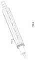
- FIG. 1illustrates a side perspective view of a device used in power assisted lipoplasty designed consistent with an embodiment of the present invention.
- FIG. 2illustrates a side perspective view of a handpiece of the device shown in FIG. 1 .
- FIG. 3illustrates a side perspective view of the handpiece shown in FIG. 2 with a motor and a removable coupler of the handpiece separated.
- FIG. 4illustrates a top perspective view of the cannula hub and removable coupler of the handpiece shown in FIG. 2 .
- FIG. 5illustrates a side perspective view of the handpiece shown in FIG. 2 without the outside shell 110 , or hub 112 .
- FIG. 6illustrates a side exploded view of the handpiece shown in FIG. 2 without the outside shell 110 , or hub 112 .
- FIG. 7illustrates a side perspective view of the removable coupler 108 connected to the cannula showing the direct path provided for flow of adipose tissue.
- FIG. 8illustrates a cross-sectional view of the removable coupler 108 cross-sectioned parallel to a central axis of the removable coupler 108 .
- FIG. 9illustrates a cross-sectional view of an embodiment of a removable coupler that includes channels for controlled venting.
- FIG. 10illustrates a system for aspiration and infiltration that implements the device 100 of FIG. 1 .
- FIG. 11illustrates a side perspective view of a second embodiment of a handpiece.
- FIG. 12illustrates a side perspective view of the handpiece shown in FIG. 11 exposing the interior of the handpiece.
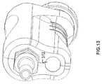
- FIG. 13illustrates a rear perspective view of the handpiece shown in FIG. 11 showing the channel within the housing when the removable couple is removed.
- FIG. 14illustrates another embodiment of a coupler and cannula that may be used for infiltration of adipose tissue.
- FIGS. 15A and 15Billustrate a portion of a patient's body before and after adipose tissue is removed, e.g., aspirated.
- FIG. 16illustrates embodiments of different angular rotations of a cannula when aspirating adipose tissue from different locations in a patient.
- the rotation of the cannulaeffects fragmentation (e.g., break up) of tissues that are then removed by aspiration through the cannula.
- the deviceis used in Power Assisted Lipoplasty (PAL) for fragmenting and removing tissue from a surgical location.
- PALPower Assisted Lipoplasty
- FIG. 1illustrates a side perspective view of a device 100 used in power assisted lipoplasty designed consistent with an embodiment of the present invention.
- device 100includes a cannula 102 with perforations 102 A.
- Adipose tissueis aspirated from a surgical site by being drawn into perforations 102 A and channel 103 of cannula 102 when a vacuum is applied.
- Cannula 102is used to provide a pathway for removing adipose tissue from a surgical site to a collection container and to provide a pathway for infiltration fluid delivered to a surgical site from a container.
- Device 100also includes a handpiece 104 that is used by a user to manipulate cannula 102 within a surgical site inside a patient.
- Handpiece 104includes a motor 106 that provides the mechanical movement of cannula 102 .
- motor 106rotates cannula 102 in a clockwise and/or counter clockwise direction(s) shown by arrows 108 .
- the rotationassists in fragmenting, e.g., breaking up, adipose tissue at a surgical site, which can then be aspirated through the cannula.
- the degree of rotation of the cannuladepends on the actual implementation.
- the cannula 102may rotate more than about 90 degrees (90°), more than about 180° or even more than about 360° in one direction (e.g., clockwise) followed by movement of more than about 90°, more than about 180° or even more than about 360° in the other direction (e.g., counter clockwise).
- the cannula 102may rotate less than about 360° in at least one direction before changing directions and rotating less than about 360° in the other direction.
- motor 106may be configured to rotate cannula 102 any desired amount in different directions.
- Motor 106is also configured to rotate cannula 102 at different rotational speeds ranging from about 50 revolutions per minute (rpm) to about 500 rpm.
- the speed of the cannularanges from about 100 rpm to about 420 rpm and motor 106 is configured to be adjusted in increments of about 80 rpm.
- the motor 106may be set to rotate the cannula at about 100 rpm, about 180 rpm, about 260 rpm, about 340 rpm, or about 420 rpm. This is merely one embodiment and motor 160 may be adjusted in any increments, in other embodiments.
- FIG. 2illustrates a side perspective view of the handpiece 104 of the device 100 shown in FIG. 1 .
- removable coupler 108that is part of handpiece 104 .
- Coupler 108is connected to cannula 102 and provides a pathway for adipose tissue that is aspirated from the surgical site or for infiltration fluid delivered to a surgical site.
- Hub 112covers the connection between cannula 102 and coupler 108 .
- housing 110which partially covers motor 106 and also provides a portion of the mechanism for connecting motor 106 to removable coupler 108 .
- housing 110includes an opening 110 A that exposes at least a portion of the motor 106 .
- FIG. 3illustrates the features of housing 110 that are used to connect motor 106 to removable coupler 108 .
- housing 110includes a number of channels 114 that engage tabs on removable coupler 108 .
- Channels 114include openings 114 A that allow tabs to be initially positioned within the channels 114 . The tabs can then be slid and secured within channels 114 .
- FIG. 4illustrates a top perspective view of the removable coupler 108 and cannula hub and shows the tabs 116 that are positioned within the channels 114 and used to engage coupler 108 with housing 110 . It should be understood that the mechanism shown in FIGS. 3 and 4 for connecting the removable coupler 108 with the motor 106 is presented merely for illustrative purposes.
- motor 106may include other features and mechanisms, such as bracket, fasteners, and/or clamp, for connecting motor 106 to removable coupler 108 .
- FIGS. 11-13illustrated below, illustrate an alternative embodiment for connecting a coupler to a motor.
- FIG. 5illustrates a side perspective view of the handpiece 100 shown in FIG. 2 , without the outside shell 110 or hub 112 .
- FIG. 5illustrates features of embodiments of the present invention.
- motor 106is located on the side of coupler 106 and cannula 102 , yet still rotates cannula 102 .
- the flow path for the adipose tissueis through cannula 102 and removable coupler 108 .
- the pathwaydoes not pass through motor 106 .
- This designis distinct from available devices in which the flow path for the adipose tissue passes through the motor that rotates the cannula. As shown in FIG.
- a center axis 107 of motor 106does not coincide with a center axis of removable coupler 109 , which is also the center axis of cannula 102 when connected to coupler 109 .
- center axis 107is substantially parallel to axis 109 .
- axis 107may not be substantially parallel to axis 109 as shown in FIG. 5 but may be positioned at some angle relative to axis 109 .
- axis 107does not substantially coincide with the flow path of adipose tissue removed from a surgical site.
- the flow pathis also used in embodiments for delivering infiltration fluid to a surgical site.
- motor 106is an electric motor.
- Use of an electric motor as motor 106may provide improvements over other devices that use vacuum driven motors. Electric motors are more reliable, more user friendly, and are easier to miniaturize to fit within a handpiece.
- FIG. 6illustrates a side exploded view of the handpiece shown in FIG. 5 without the outside shell 110 and with hub 112 .
- FIG. 6illustrates the components used to transfer the motion from motor 106 to the cannula 102 .
- Motor 106includes a shaft 106 B which rotates. Connected to shaft 106 B is gear 118 which engages gear 120 .
- Gear 120is connected to cannula 102 .
- Gears 118 and 120transfer the rotational motion of shaft 106 B of motor 106 to cannula 102 .
- FIG. 6illustrates only two gears, other embodiments may include more complicated designs with additional gears, shafts, pulleys, or other mechanical components for transferring motion from motor 106 to rotation of a cannula.
- gear 118is connected to additional components which then transfer the movement of gear 118 to gear 120 .
- motor 106includes an outside surface 106 A that may be molded with material such as silicone to allow a user to more comfortably grip handpiece 104 . Additionally, the molded material may have some ornamental features.
- Removable coupler 108also includes indentations 108 A that can accommodate the fingers of a user. The indentations 108 A can be customized or standardized. Outside surface 106 A and indentations 108 A are merely some examples of ergonomic features that may be incorporated into handpiece 100 . Those with skill in the art will appreciate that additional features may be added in other embodiments.
- FIG. 6also shows is a grove 119 on the back end of cannula 102 .
- Groove 119in embodiments is used to secure an o-ring onto cannula 102 .
- the o-ringhelps to provide a seal between the cannula 102 and a channel 130 of removable coupler 108 , helping to maintain a vacuum.
- the motor 106may include a swivel mechanism at location 127 that allows the motor 106 to rotate with respect to the cable. This is useful so that a user does not have to work against the resistance of the cable when manipulating the handpiece, which reduces the strain on a users hand or wrist.
- the removable couplermay also include a swivel mechanism at location 123 that also allows the coupler to rotate with respect to tubing connected to the coupler 108 . This also reduces the strain on a user.
- FIG. 7illustrates a side perspective view of the removable coupler 108 connected to the cannula showing the direct path provided for flow of adipose tissue.
- One feature of embodiments of the present inventionis the ability to provide a direct path from a tip 124 of the cannula 102 where adipose tissue enters the cannula 102 to a location 126 where tubing that provides the vacuum is connected to the handpiece.
- FIG. 7illustrates the flow of adipose tissue in the direction noted by arrow 128 . As shown in FIG. 7 there is a direct path from tip 124 to location 126 .
- channel 103 of cannula 102is substantially collinear with a channel 130 ( FIG. 8 ) of coupler 108 . It is noted that in some embodiments, the channel 103 of cannula 102 or the channel 130 of the removable coupler 108 may not be substantially straight, but may include some curves or twists. In those embodiment in which coupler 108 and cannula 102 are used to deliver infiltration fluid to a surgical site, the flow of fluid is opposite the direction noted by arrow 128 .
- a handpiece with a flow path that does not pass through motor 106provides a number of improvements over handpieces in which the flow path of adipose tissue (or infiltration fluid) does pass through a motor.
- a leak in the portion of the flow path that passes through the motorcan damage the motor, which requires replacement of the entire handpiece.
- leaks in the portion of the flow path that passes through the motorare not easily repaired.
- the handpiecemay need to be replaced because of the difficulty in repairing the leaks or breaks in the portion of the flow path that passes through the motor.
- having the flow path pass through the removable coupler 108allows easy replacement of the removable coupler in the event of any leaks or breaks.
- the motor 106can be sealed so that any fluid that leaks from a broken coupler does not enter the motor 106 .
- FIG. 8illustrates a feature of some embodiments that helps to preserve the adipose tissue that is removed from the surgical site.
- FIG. 8illustrates a cross-sectional view of the removable coupler 108 cross-sectioned parallel to a central axis of the removable coupler 108 .
- removable coupler 108includes a central channel 130 that provides the pathway for adipose tissue.
- channel 130is substantially collinear with the channel 103 of cannula 102 (see FIG. 7 ).
- channel 130is in embodiments tapered. That is, the diameter 132 at one end of channel 130 is less than the diameter 134 at a second end of channel 130 .
- the taper of channel 130reduces the velocity of the adipose tissue as it flows through channel 130 across the length of the removable coupler 108 . The reduction in velocity may help to reduce damage that is done to the cells as they flow through coupler 108 . The adipose tissue may then provide better results when introduced into a patient.
- FIG. 8also shows a cavity 136 where the cannula 102 is connected to the removable coupler 108 .
- FIG. 9illustrates a cross-sectional view of an embodiment of a removable coupler 140 that includes channels for controlled venting.
- the removable coupler 140includes a cavity 142 (similar to cavity 136 of coupler 108 ) where a cannula can be connected to the removable coupler 140 .
- cannula 102 with groove 119and an o-ring positioned within groove 119 , can be positioned within cavity 142 .
- venting channels 144that allow air to flow between the interior walls of cavity 142 and a cannula that is positioned within cavity 142 .
- venting channels 144are designed to allow a certain amount of air to flow between the interior walls of cavity 142 and a cannula or an o-ring on the cannula. This controlled venting allows continual flow along a pathway between a surgical site and a collection container for collecting adipose tissue removed from the surgical site. Even if adipose tissue blocks the pathway upstream of the vents, the venting feature allows a continual flow of material from the surgical site to the collection container. As those with skill in the art will appreciate, the combination of venting and a rotating cannula is not found in conventional devices. As can be appreciated, to provide different amounts of venting, venting channels 144 may be of different dimensions, and a coupler may include one or more venting channels 144 .
- FIG. 10illustrates a system 200 in accordance with one embodiment of the present invention.
- System 200uses the device 100 of FIG. 1 .
- System 200also includes a console 202 that is connected to the motor 106 of device 100 .
- the console 202may include a number of components that helps drive motor 106 .
- console 202may include a power supply 204 as well as logic 206 for sensing and controlling the amount and direction of rotation of cannula 102 .
- logic 206may be hardware or may include aspects of hardware and software.
- logic 206includes a processor that executes instructions implemented in software.
- the softwareis stored in a memory 205 within console 202 .
- the logic 206can provide precise control over the speed and angular rotation of the cannula 102 .
- the logic 206can be programmed to change the speed and the amount of rotation based on various factors including, but not limited to, the specific procedure being performed (e.g., infiltration or aspiration), the location of the surgical site, the amount of adipose tissue that will be aspirated, the amount of fluid being used to infiltrate a surgical site, or the type of fluid used to infiltrate a surgical site.
- This controlis distinct from other devices that use a stepper motor that does not require logic to control the rotation of cannula, e.g., an open loop embodiment.
- console 202may provide controls that allow a user to enter settings for the rotation of the cannula.
- console 202may include: knobs, buttons, dials, LCD display(s) or other controls that allow a user to enter settings to control logic 206 and ultimately the speed and angle of rotation of cannula 102 .
- System 200also includes a pump 214 that creates a vacuum within collection container 214 .
- the vacuum created by pump 214creates a vacuum within tubing 210 , which is connected to the removable coupler 108 .
- the vacuumdraws the adipose tissue from the surgical site through cannula 102 , coupler 108 , tubing 210 and into container 214 .
- the adipose tissuemay be store within container 214 until disposed of or further processed for reintroduction into a patient.
- the vacuumis not used in any way to affect rotation of the cannula.
- system 200may be used for infiltration as well as aspiration.
- system 200will include optional infiltration system 216 , which includes tubing 218 connected to a pump 220 .
- Pump 220when operated pumps infiltration liquid from reservoir 222 through tubing 224 , tubing 218 , tubing 210 , removable coupler 108 , and cannula 102 to the surgical site.
- a valve 225may be used to ensure that infiltration liquid does not enter the aspiration system.
- cannula 102may be rotated during infiltration of the surgical site. The rotation of cannula 102 may be in directions and amounts that are different than the rotation of cannula 102 during aspiration. In other embodiments, the rotation of cannula 102 may be the same during infiltration and aspiration.
- FIG. 11illustrates a side perspective view of a second embodiment of a handpiece 304 according to the present invention.
- Handpiece 304also includes a removable coupler 308 .
- Handpiece 304includes a housing 310 that covers a majority of a motor 306 and a majority of the removable coupler 308 .
- removable coupler 308is positioned within a channel 312 ( FIG. 13 ) of housing 310 .
- FIG. 12illustrates a side perspective view of the handpiece 304 with a portion of housing 310 missing to expose the interior of the handpiece 304 .
- FIG. 13illustrates a rear perspective view of the handpiece 304 showing the channel 312 when removable coupler 308 is not positioned within the channel 312 .
- handpiece 304includes a motor 306 positioned within housing 310 .
- the removable coupler 308is also positioned within housing 310 in channel 312 .
- the removable coupler 308can be inserted into, and removed from, channel 312 , and when positioned within channel 312 is mechanically secured within channel 312 .
- removable coupler 308may include one or more ridges along its length that fit within grooves in channel 312 .
- the removable coupler 308may include o-rings that contact the interior surface of channel 312 to secure coupler 308 within the channel. These are merely some examples, and any mechanical features for securing coupler 308 in channel 312 may be used.
- Coupler 308also includes some anti-rotation features.
- coupler 308has a flat surface 316 on the top and another flat surface (not shown) on the bottom.
- the top surface 316may contact portions of channel 312 and portions of motor 306 to prevent it from rotating when a cannula connected to coupler 308 is being rotated by motor 306 .
- removable coupler 308can be easily replaced if there is a break or leak in coupler 308 . It is easily removed and replaced.
- different couplersmay be used with the same handpiece 304 .
- a first couplermay be used when handpiece 304 is used for infiltration of adipose tissues.
- the first couplermay include features that allow it to easily connect to an infiltration system, or have other features that make it appropriate for use in infiltration of adipose tissues (e.g., FIGS. 14 a - 14 C).
- a second coupler with different featurescan then be used when aspirating tissue from a patient.
- FIGS. 14A-14Cillustrate an embodiment of a coupler 408 and a cannula 402 that are used in some embodiments of the present invention for infiltration of adipose tissue.
- FIG. 14 Aillustrates the coupler 408
- FIG. 14Billustrates the cannula 402
- FIG. 14Cillustrates the cannula 402 when connected to, and positioned within, coupler 408 .
- coupler 408includes a channel 430 that is part of a flow path for infiltration fluid.
- a coupling 450is used to connect coupler 408 to a source of fluid, such as infiltration system 216 ( FIG. 10 ).
- coupler 450has threads that allow coupler 408 to connect to the source of infiltration fluid.
- Coupler 408also includes a cavity 436 where at least a portion of a cannula, such as cannula 402 connects to coupler 408 .
- a hole 420is also included in coupler 408 . As described in greater detail below with respect to FIG. 14C , the hole 420 allows infiltration fluid to escape the coupler 408 if the cannula 402 is not sealed properly with the coupler 408 .
- the cannula 402includes two hubs 452 and 454 .
- Each of hubs 452 and 454includes features for creating a seal with cannula 402 and prevent infiltration fluid from leaking.
- Hub 452includes a grove 462 into which an o-ring 462 A is positioned.
- Hub 454includes grooves 456 , 458 , and 460 .
- o-rings 456 A, 458 B, and 460 Care positioned in grooves 456 , 458 , and 460 respectively to create a seal between coupler 408 and cannula 402 .
- cannula 402slides into channel 430 of coupler 402 .
- the o-ring 462 Acontacts and creates a seal with the inside surface of cavity 432 .
- o-rings 456 A, 458 A, and 460 Acontact the inside surface of channel 403 and also create a seal.
- Hole 420 of coupler 408is positioned between o-rings 458 A and 460 A. The hole 420 allows any infiltration fluid that leaks around o-rings 456 A and 458 A to escape and not leak into other areas, such a motor that may be connected to coupler 408 .
- the presence of the two hubs 452 and 454provides a more robust connection between coupler 408 and cannula 402 .
- a momentmay be created about a connection point between the coupler 408 and cannula 402 .
- Having two hubscreates two connection points and makes it less likely that the connection, and the seal, between the coupler 408 and cannula 402 will fail.
- cannula 402 and coupler 408are described as useful for infiltration of adipose tissue. They may be used in embodiments for aspiration of adipose tissue. Features such as having two hubs are also useful when aspirating adipose tissue.
- FIGS. 15A and 15Billustrates a portion of a patient's body including layers of skin 502 , a subcutaneous layer of fat 504 from which the adipose tissue is removed, and some other anatomical layer 506 (e.g. muscle tissue). Although shown as distinct layers in the drawings, in fact, layers such as 504 and 506 can be interdispersed particularly at their boundary.
- FIGS. 15A and 15Bthe portion of layer 504 that is near the skin 502 is labeled 504 A, while the portion that is deeper is labeled 504 B.
- FIG. 15Ashows an embodiment where no adipose tissue has yet been removed from a patient.
- FIG. 15Bshows that adipose tissue has been removed from a patient's body.
- a volume of adipose tissuehas been removed from surgical site, location 508 , which is in the portion of layer 504 labeled as 504 A, near skin 502 .
- an indentation 512has formed on the surface of skin 502 .
- the indentation 508is not dangerous, but is not aesthetically pleasing.
- a surgeonmay need to perform some sculpting, i.e.
- removing adipose tissue from locations deeper in layer 504is less likely to cause artifacts on the skin surface that affect the appearance of the skin.
- FIG. 16two cross-sections of a cannula 516 , perpendicular to a center axis of the cannula, are shown. The cross-sections are through a perforation 518 in cannula 516 .
- the adipose tissueis removed from a patient through aspiration, namely by applying a vacuum within cannula 516 which causes the adipose tissue to enter cannula 516 through perforation 518 .
- FIG. 16also shows skin layer 502 , and labels 504 A and 504 B.
- the top cross section shown in FIG. 16illustrate the angle of rotation that the cannula 516 will travel, in one embodiment of the present invention, when adipose tissue is being removed from portion 504 A of layer 504 .
- the surgical siteis within portion 504 A.
- the cannulais limited in its rotation so that perforation 518 is not allowed to go beyond about 90° from its original position 520 in either clockwise or counterclockwise directions. This limitation prevents adipose tissue from being removed from a location that is too close to skin layer 502 , thereby preventing formation of indentations on the surface of skin 502 .
- the motore.g., motor 106 or 306
- the motorthat is rotating cannula 516 is set so that the rotation of cannula 516 is no more than about 90° in either clockwise or counterclockwise directions.
- the motormay be set to allow rotation beyond 90° such as about 100° or about 110° but still limit the rotation to prevent adipose tissue from being removed from a location too close to skin 502 .
- the motorin addition to limiting the rotation of cannula 516 , the motor may also be configured to limit the rotational speed of cannula 516 when removing adipose tissue from layer 504 A.
- the motormay be set to lower speeds, such as from about 100 rpm to about 280 rpm so that there is not as much energy being applied to the adipose tissue near the skin 502 .
- the rate at which the adipose tissue is removedis slower when the cannula is rotated at lower speeds because the adipose tissue is not being fragmented as quickly. This allows a surgeon time to view the skin surface and ensure that it is being contoured as desired by the surgeon.
- similar angles and speedsare used when infiltrating adipose tissue in portion 504 A of layer 504 .
- the bottom cross section shown in FIG. 16illustrate the angle of rotation that the cannula 516 will travel, in one embodiment of the present invention, when adipose tissue is being removed from portion 504 B of layer 504 . That is, the surgical site is within portion 504 B. As is shown, the cannula 516 may rotate so that perforation 518 rotates 360° from its original position 520 in either clockwise or counterclockwise directions. When removing adipose tissue from portion 504 B, which is deeper in layer 504 , there is less risk of creating indentations on the surface of skin 502 ; as a result the cannula 516 is allowed to rotate 360° to remove adipose tissue all the way around cannula 516 . In these embodiments, the motor, e.g., motor 106 or 306 , that is rotating cannula 516 is set so that the rotation of cannula 516 is 360°, or more, in either clockwise or counterclockwise directions.
- the motormay also be configured to rotate cannula 516 at relatively higher speeds when removing adipose tissue from layer 504 B.
- the motormay be set to speeds, such as from about 360 rpm to about 420 rpm, so that the adipose tissue is fragmented and removed relatively quickly. Removing adipose tissue more quickly from portion 504 B shortens the procedure time and may allow a surgeon more time to sculpt the patient when removing tissue closer to skin 502 .
- similar angles and speedsare used when infiltrating adipose tissue in portion 504 B of layer 504 .
- FIGS. 14A-15is made for illustrative purposes only to show combinations of amount of rotation and speeds that a motor consistent with the present invention may implement.
- motors of the present inventionmay have a variety of settings for both the amount of rotation and the rotational speed. A surgeon can then decide the appropriate combination of amount and speed for a particular procedure.
Landscapes
- Health & Medical Sciences (AREA)
- Life Sciences & Earth Sciences (AREA)
- Surgery (AREA)
- Heart & Thoracic Surgery (AREA)
- Public Health (AREA)
- Animal Behavior & Ethology (AREA)
- Biomedical Technology (AREA)
- Veterinary Medicine (AREA)
- Engineering & Computer Science (AREA)
- General Health & Medical Sciences (AREA)
- Medical Informatics (AREA)
- Molecular Biology (AREA)
- Nuclear Medicine, Radiotherapy & Molecular Imaging (AREA)
- Orthopedic Medicine & Surgery (AREA)
- Vascular Medicine (AREA)
- Anesthesiology (AREA)
- Hematology (AREA)
- External Artificial Organs (AREA)
- Surgical Instruments (AREA)
Abstract
Description
Claims (10)
Priority Applications (3)
| Application Number | Priority Date | Filing Date | Title |
|---|---|---|---|
| US13/249,113US8864747B2 (en) | 2010-09-29 | 2011-09-29 | Power assisted lipoplasty |
| US14/496,362US10004836B2 (en) | 2010-09-29 | 2014-09-25 | Power assisted lipoplasty |
| US16/003,362US20180361035A1 (en) | 2010-09-29 | 2018-06-08 | Power assisted lipoplasty |
Applications Claiming Priority (2)
| Application Number | Priority Date | Filing Date | Title |
|---|---|---|---|
| US38797810P | 2010-09-29 | 2010-09-29 | |
| US13/249,113US8864747B2 (en) | 2010-09-29 | 2011-09-29 | Power assisted lipoplasty |
Related Child Applications (1)
| Application Number | Title | Priority Date | Filing Date |
|---|---|---|---|
| US14/496,362DivisionUS10004836B2 (en) | 2010-09-29 | 2014-09-25 | Power assisted lipoplasty |
Publications (2)
| Publication Number | Publication Date |
|---|---|
| US20120078234A1 US20120078234A1 (en) | 2012-03-29 |
| US8864747B2true US8864747B2 (en) | 2014-10-21 |
Family
ID=45871371
Family Applications (3)
| Application Number | Title | Priority Date | Filing Date |
|---|---|---|---|
| US13/249,113Active2032-06-30US8864747B2 (en) | 2010-09-29 | 2011-09-29 | Power assisted lipoplasty |
| US14/496,362Active2033-05-05US10004836B2 (en) | 2010-09-29 | 2014-09-25 | Power assisted lipoplasty |
| US16/003,362AbandonedUS20180361035A1 (en) | 2010-09-29 | 2018-06-08 | Power assisted lipoplasty |
Family Applications After (2)
| Application Number | Title | Priority Date | Filing Date |
|---|---|---|---|
| US14/496,362Active2033-05-05US10004836B2 (en) | 2010-09-29 | 2014-09-25 | Power assisted lipoplasty |
| US16/003,362AbandonedUS20180361035A1 (en) | 2010-09-29 | 2018-06-08 | Power assisted lipoplasty |
Country Status (6)
| Country | Link |
|---|---|
| US (3) | US8864747B2 (en) |
| EP (2) | EP3777721B1 (en) |
| JP (1) | JP2013542002A (en) |
| KR (1) | KR20130110171A (en) |
| AU (1) | AU2011312413A1 (en) |
| WO (1) | WO2012047720A1 (en) |
Cited By (51)
| Publication number | Priority date | Publication date | Assignee | Title |
|---|---|---|---|---|
| US11744604B2 (en) | 2017-12-28 | 2023-09-05 | Cilag Gmbh International | Surgical instrument with a hardware-only control circuit |
| US11751958B2 (en) | 2017-12-28 | 2023-09-12 | Cilag Gmbh International | Surgical hub coordination of control and communication of operating room devices |
| US11771487B2 (en) | 2017-12-28 | 2023-10-03 | Cilag Gmbh International | Mechanisms for controlling different electromechanical systems of an electrosurgical instrument |
| US11775682B2 (en) | 2017-12-28 | 2023-10-03 | Cilag Gmbh International | Data stripping method to interrogate patient records and create anonymized record |
| US11779337B2 (en) | 2017-12-28 | 2023-10-10 | Cilag Gmbh International | Method of using reinforced flexible circuits with multiple sensors to optimize performance of radio frequency devices |
| US11793537B2 (en) | 2017-10-30 | 2023-10-24 | Cilag Gmbh International | Surgical instrument comprising an adaptive electrical system |
| US11801098B2 (en) | 2017-10-30 | 2023-10-31 | Cilag Gmbh International | Method of hub communication with surgical instrument systems |
| US11818052B2 (en) | 2017-12-28 | 2023-11-14 | Cilag Gmbh International | Surgical network determination of prioritization of communication, interaction, or processing based on system or device needs |
| US11832899B2 (en) | 2017-12-28 | 2023-12-05 | Cilag Gmbh International | Surgical systems with autonomously adjustable control programs |
| US11839396B2 (en) | 2018-03-08 | 2023-12-12 | Cilag Gmbh International | Fine dissection mode for tissue classification |
| US11844579B2 (en) | 2017-12-28 | 2023-12-19 | Cilag Gmbh International | Adjustments based on airborne particle properties |
| US11857152B2 (en) | 2017-12-28 | 2024-01-02 | Cilag Gmbh International | Surgical hub spatial awareness to determine devices in operating theater |
| US11864845B2 (en) | 2017-12-28 | 2024-01-09 | Cilag Gmbh International | Sterile field interactive control displays |
| US11864728B2 (en) | 2017-12-28 | 2024-01-09 | Cilag Gmbh International | Characterization of tissue irregularities through the use of mono-chromatic light refractivity |
| US11871901B2 (en) | 2012-05-20 | 2024-01-16 | Cilag Gmbh International | Method for situational awareness for surgical network or surgical network connected device capable of adjusting function based on a sensed situation or usage |
| US11890065B2 (en) | 2017-12-28 | 2024-02-06 | Cilag Gmbh International | Surgical system to limit displacement |
| US11896443B2 (en) | 2017-12-28 | 2024-02-13 | Cilag Gmbh International | Control of a surgical system through a surgical barrier |
| US11896322B2 (en) | 2017-12-28 | 2024-02-13 | Cilag Gmbh International | Sensing the patient position and contact utilizing the mono-polar return pad electrode to provide situational awareness to the hub |
| US11903587B2 (en) | 2017-12-28 | 2024-02-20 | Cilag Gmbh International | Adjustment to the surgical stapling control based on situational awareness |
| US11911045B2 (en) | 2017-10-30 | 2024-02-27 | Cllag GmbH International | Method for operating a powered articulating multi-clip applier |
| US11925350B2 (en) | 2019-02-19 | 2024-03-12 | Cilag Gmbh International | Method for providing an authentication lockout in a surgical stapler with a replaceable cartridge |
| US11931027B2 (en) | 2018-03-28 | 2024-03-19 | Cilag Gmbh Interntional | Surgical instrument comprising an adaptive control system |
| US11969216B2 (en) | 2017-12-28 | 2024-04-30 | Cilag Gmbh International | Surgical network recommendations from real time analysis of procedure variables against a baseline highlighting differences from the optimal solution |
| US11969142B2 (en) | 2017-12-28 | 2024-04-30 | Cilag Gmbh International | Method of compressing tissue within a stapling device and simultaneously displaying the location of the tissue within the jaws |
| US11986233B2 (en) | 2018-03-08 | 2024-05-21 | Cilag Gmbh International | Adjustment of complex impedance to compensate for lost power in an articulating ultrasonic device |
| US11986185B2 (en) | 2018-03-28 | 2024-05-21 | Cilag Gmbh International | Methods for controlling a surgical stapler |
| US11998193B2 (en) | 2017-12-28 | 2024-06-04 | Cilag Gmbh International | Method for usage of the shroud as an aspect of sensing or controlling a powered surgical device, and a control algorithm to adjust its default operation |
| US12009095B2 (en) | 2017-12-28 | 2024-06-11 | Cilag Gmbh International | Real-time analysis of comprehensive cost of all instrumentation used in surgery utilizing data fluidity to track instruments through stocking and in-house processes |
| US12029506B2 (en) | 2017-12-28 | 2024-07-09 | Cilag Gmbh International | Method of cloud based data analytics for use with the hub |
| US12035983B2 (en) | 2017-10-30 | 2024-07-16 | Cilag Gmbh International | Method for producing a surgical instrument comprising a smart electrical system |
| US12035890B2 (en) | 2017-12-28 | 2024-07-16 | Cilag Gmbh International | Method of sensing particulate from smoke evacuated from a patient, adjusting the pump speed based on the sensed information, and communicating the functional parameters of the system to the hub |
| US12042207B2 (en) | 2017-12-28 | 2024-07-23 | Cilag Gmbh International | Estimating state of ultrasonic end effector and control system therefor |
| US12048496B2 (en) | 2017-12-28 | 2024-07-30 | Cilag Gmbh International | Adaptive control program updates for surgical hubs |
| US12062442B2 (en) | 2017-12-28 | 2024-08-13 | Cilag Gmbh International | Method for operating surgical instrument systems |
| US12059169B2 (en) | 2017-12-28 | 2024-08-13 | Cilag Gmbh International | Controlling an ultrasonic surgical instrument according to tissue location |
| US12059218B2 (en) | 2017-10-30 | 2024-08-13 | Cilag Gmbh International | Method of hub communication with surgical instrument systems |
| US12076010B2 (en) | 2017-12-28 | 2024-09-03 | Cilag Gmbh International | Surgical instrument cartridge sensor assemblies |
| US12121256B2 (en) | 2018-03-08 | 2024-10-22 | Cilag Gmbh International | Methods for controlling temperature in ultrasonic device |
| US12127729B2 (en) | 2017-12-28 | 2024-10-29 | Cilag Gmbh International | Method for smoke evacuation for surgical hub |
| US12133773B2 (en) | 2017-12-28 | 2024-11-05 | Cilag Gmbh International | Surgical hub and modular device response adjustment based on situational awareness |
| US12133709B2 (en) | 2017-12-28 | 2024-11-05 | Cilag Gmbh International | Communication hub and storage device for storing parameters and status of a surgical device to be shared with cloud based analytics systems |
| US12144518B2 (en) | 2017-12-28 | 2024-11-19 | Cilag Gmbh International | Surgical systems for detecting end effector tissue distribution irregularities |
| US12207817B2 (en) | 2017-12-28 | 2025-01-28 | Cilag Gmbh International | Safety systems for smart powered surgical stapling |
| US12226166B2 (en) | 2017-12-28 | 2025-02-18 | Cilag Gmbh International | Surgical instrument with a sensing array |
| US12226151B2 (en) | 2017-12-28 | 2025-02-18 | Cilag Gmbh International | Capacitive coupled return path pad with separable array elements |
| US12295674B2 (en) | 2017-12-28 | 2025-05-13 | Cilag Gmbh International | Usage and technique analysis of surgeon / staff performance against a baseline to optimize device utilization and performance for both current and future procedures |
| US12310586B2 (en) | 2017-12-28 | 2025-05-27 | Cilag Gmbh International | Method for adaptive control schemes for surgical network control and interaction |
| US12318152B2 (en) | 2017-12-28 | 2025-06-03 | Cilag Gmbh International | Computer implemented interactive surgical systems |
| US12329467B2 (en) | 2017-10-30 | 2025-06-17 | Cilag Gmbh International | Method of hub communication with surgical instrument systems |
| US12383115B2 (en) | 2017-12-28 | 2025-08-12 | Cilag Gmbh International | Method for smart energy device infrastructure |
| US12396806B2 (en) | 2017-12-28 | 2025-08-26 | Cilag Gmbh International | Adjustment of a surgical device function based on situational awareness |
Families Citing this family (11)
| Publication number | Priority date | Publication date | Assignee | Title |
|---|---|---|---|---|
| USD680640S1 (en)* | 2011-09-29 | 2013-04-23 | Sound Surgical Technologies Llc | Handpiece |
| US11266384B2 (en) | 2018-04-20 | 2022-03-08 | Johnson & Johnson Surgical Vision, Inc. | Ergonomic handpiece |
| KR102084618B1 (en)* | 2018-08-29 | 2020-03-04 | 계명대학교 산학협력단 | A boring device to pass true lumen of chronic total occlusion lesion |
| WO2020191246A1 (en) | 2019-03-19 | 2020-09-24 | The Broad Institute, Inc. | Methods and compositions for editing nucleotide sequences |
| US12171930B2 (en) | 2019-05-17 | 2024-12-24 | Johnson & Johnson Surgical Vision, Inc. | Ergonomic phacoemulsification handpiece |
| USD946146S1 (en) | 2020-05-15 | 2022-03-15 | Johnson & Johnson Surgical Vision, Inc. | Surgical handpiece |
| KR102530666B1 (en) | 2021-01-04 | 2023-05-11 | 주식회사 엘에이치바이오메드 | Power assisted liposuction device |
| US12349934B2 (en)* | 2021-09-23 | 2025-07-08 | Gyrus Acmi, Inc. | Medical device with removable motor |
| KR102446321B1 (en)* | 2021-12-16 | 2022-09-22 | 정병태 | Osmidrosis triple removal cannula device for aspirating sweat glands |
| KR102479294B1 (en) | 2022-08-10 | 2022-12-21 | 주식회사 엘에이치바이오메드 | Ultrasonic device for ultrasound assisted lipoplasty |
| CN116350309A (en)* | 2023-02-09 | 2023-06-30 | 中国人民解放军海军军医大学第一附属医院 | Ring pull type retroperitoneal fat removal equipment |
Citations (4)
| Publication number | Priority date | Publication date | Assignee | Title |
|---|---|---|---|---|
| US5653698A (en) | 1995-01-13 | 1997-08-05 | Sanofi Winthrop, Inc. | Coupling systems for saftey cannula |
| US5980545A (en)* | 1996-05-13 | 1999-11-09 | United States Surgical Corporation | Coring device and method |
| US6258054B1 (en)* | 1997-03-11 | 2001-07-10 | Microaire Surgical Instruments, Inc. | Power assisted liposuction and lipoinjection equipment |
| US20080319468A1 (en)* | 2003-02-24 | 2008-12-25 | Senorx, Inc. | Biopsy device with selectable tissue receiving aperature orientation and site illumination |
Family Cites Families (11)
| Publication number | Priority date | Publication date | Assignee | Title |
|---|---|---|---|---|
| US4735605A (en)* | 1986-09-15 | 1988-04-05 | Swartz Barry E | Lipectomy device having round cutting edges |
| US5013300A (en)* | 1989-03-09 | 1991-05-07 | Williams James D | Apparatus for suction lipectomy surgery |
| US6129701A (en)* | 1998-11-19 | 2000-10-10 | Sound Surgical Technologies, Llc | Vented aspirator and method |
| US6638238B1 (en) | 1999-12-09 | 2003-10-28 | The Regents Of The University Of California | Liposuction cannula device and method |
| US20020151874A1 (en)* | 2001-04-12 | 2002-10-17 | Kolster Alwin H. | Liposuction cannula device and method |
| US8052672B2 (en)* | 2001-06-06 | 2011-11-08 | LENR Solutions, Inc. | Fat removal and nerve protection device and method |
| US7776004B2 (en)* | 2002-05-22 | 2010-08-17 | Surgimark, Inc. | Aspirator sleeve and suction handle |
| US9095366B2 (en)* | 2007-04-06 | 2015-08-04 | Hologic, Inc. | Tissue cutter with differential hardness |
| CN101711129B (en)* | 2007-05-17 | 2012-07-04 | 普罗德克斯有限公司 | Handheld medical device |
| WO2009064750A1 (en)* | 2007-11-12 | 2009-05-22 | Microaire Surgical Instruments | Surgical liposuction instrument with radiant energy source |
| KR101040690B1 (en)* | 2008-10-21 | 2011-06-10 | 최종수 | Liposuction handle |
- 2011
- 2011-09-29JPJP2013531868Apatent/JP2013542002A/ennot_activeWithdrawn
- 2011-09-29USUS13/249,113patent/US8864747B2/enactiveActive
- 2011-09-29EPEP20193290.2Apatent/EP3777721B1/enactiveActive
- 2011-09-29AUAU2011312413Apatent/AU2011312413A1/ennot_activeAbandoned
- 2011-09-29WOPCT/US2011/054041patent/WO2012047720A1/enactiveApplication Filing
- 2011-09-29KRKR20137010380Apatent/KR20130110171A/ennot_activeWithdrawn
- 2011-09-29EPEP11831343.6Apatent/EP2621374A4/ennot_activeCeased
- 2014
- 2014-09-25USUS14/496,362patent/US10004836B2/enactiveActive
- 2018
- 2018-06-08USUS16/003,362patent/US20180361035A1/ennot_activeAbandoned
Patent Citations (4)
| Publication number | Priority date | Publication date | Assignee | Title |
|---|---|---|---|---|
| US5653698A (en) | 1995-01-13 | 1997-08-05 | Sanofi Winthrop, Inc. | Coupling systems for saftey cannula |
| US5980545A (en)* | 1996-05-13 | 1999-11-09 | United States Surgical Corporation | Coring device and method |
| US6258054B1 (en)* | 1997-03-11 | 2001-07-10 | Microaire Surgical Instruments, Inc. | Power assisted liposuction and lipoinjection equipment |
| US20080319468A1 (en)* | 2003-02-24 | 2008-12-25 | Senorx, Inc. | Biopsy device with selectable tissue receiving aperature orientation and site illumination |
Non-Patent Citations (1)
| Title |
|---|
| International Search Report dated Jan. 17, 2012, issued in Application Serial No. PCT/US2011/54041, 8 pp. |
Cited By (63)
| Publication number | Priority date | Publication date | Assignee | Title |
|---|---|---|---|---|
| US11871901B2 (en) | 2012-05-20 | 2024-01-16 | Cilag Gmbh International | Method for situational awareness for surgical network or surgical network connected device capable of adjusting function based on a sensed situation or usage |
| US12329467B2 (en) | 2017-10-30 | 2025-06-17 | Cilag Gmbh International | Method of hub communication with surgical instrument systems |
| US12121255B2 (en) | 2017-10-30 | 2024-10-22 | Cilag Gmbh International | Electrical power output control based on mechanical forces |
| US12059218B2 (en) | 2017-10-30 | 2024-08-13 | Cilag Gmbh International | Method of hub communication with surgical instrument systems |
| US12035983B2 (en) | 2017-10-30 | 2024-07-16 | Cilag Gmbh International | Method for producing a surgical instrument comprising a smart electrical system |
| US11793537B2 (en) | 2017-10-30 | 2023-10-24 | Cilag Gmbh International | Surgical instrument comprising an adaptive electrical system |
| US11801098B2 (en) | 2017-10-30 | 2023-10-31 | Cilag Gmbh International | Method of hub communication with surgical instrument systems |
| US11925373B2 (en) | 2017-10-30 | 2024-03-12 | Cilag Gmbh International | Surgical suturing instrument comprising a non-circular needle |
| US11819231B2 (en) | 2017-10-30 | 2023-11-21 | Cilag Gmbh International | Adaptive control programs for a surgical system comprising more than one type of cartridge |
| US11911045B2 (en) | 2017-10-30 | 2024-02-27 | Cllag GmbH International | Method for operating a powered articulating multi-clip applier |
| US12009095B2 (en) | 2017-12-28 | 2024-06-11 | Cilag Gmbh International | Real-time analysis of comprehensive cost of all instrumentation used in surgery utilizing data fluidity to track instruments through stocking and in-house processes |
| US12144518B2 (en) | 2017-12-28 | 2024-11-19 | Cilag Gmbh International | Surgical systems for detecting end effector tissue distribution irregularities |
| US12396806B2 (en) | 2017-12-28 | 2025-08-26 | Cilag Gmbh International | Adjustment of a surgical device function based on situational awareness |
| US11857152B2 (en) | 2017-12-28 | 2024-01-02 | Cilag Gmbh International | Surgical hub spatial awareness to determine devices in operating theater |
| US11864845B2 (en) | 2017-12-28 | 2024-01-09 | Cilag Gmbh International | Sterile field interactive control displays |
| US11864728B2 (en) | 2017-12-28 | 2024-01-09 | Cilag Gmbh International | Characterization of tissue irregularities through the use of mono-chromatic light refractivity |
| US12383115B2 (en) | 2017-12-28 | 2025-08-12 | Cilag Gmbh International | Method for smart energy device infrastructure |
| US11890065B2 (en) | 2017-12-28 | 2024-02-06 | Cilag Gmbh International | Surgical system to limit displacement |
| US11896443B2 (en) | 2017-12-28 | 2024-02-13 | Cilag Gmbh International | Control of a surgical system through a surgical barrier |
| US11896322B2 (en) | 2017-12-28 | 2024-02-13 | Cilag Gmbh International | Sensing the patient position and contact utilizing the mono-polar return pad electrode to provide situational awareness to the hub |
| US11903587B2 (en) | 2017-12-28 | 2024-02-20 | Cilag Gmbh International | Adjustment to the surgical stapling control based on situational awareness |
| US11832899B2 (en) | 2017-12-28 | 2023-12-05 | Cilag Gmbh International | Surgical systems with autonomously adjustable control programs |
| US11918302B2 (en) | 2017-12-28 | 2024-03-05 | Cilag Gmbh International | Sterile field interactive control displays |
| US11751958B2 (en) | 2017-12-28 | 2023-09-12 | Cilag Gmbh International | Surgical hub coordination of control and communication of operating room devices |
| US11818052B2 (en) | 2017-12-28 | 2023-11-14 | Cilag Gmbh International | Surgical network determination of prioritization of communication, interaction, or processing based on system or device needs |
| US12318152B2 (en) | 2017-12-28 | 2025-06-03 | Cilag Gmbh International | Computer implemented interactive surgical systems |
| US11969216B2 (en) | 2017-12-28 | 2024-04-30 | Cilag Gmbh International | Surgical network recommendations from real time analysis of procedure variables against a baseline highlighting differences from the optimal solution |
| US11969142B2 (en) | 2017-12-28 | 2024-04-30 | Cilag Gmbh International | Method of compressing tissue within a stapling device and simultaneously displaying the location of the tissue within the jaws |
| US12310586B2 (en) | 2017-12-28 | 2025-05-27 | Cilag Gmbh International | Method for adaptive control schemes for surgical network control and interaction |
| US12295674B2 (en) | 2017-12-28 | 2025-05-13 | Cilag Gmbh International | Usage and technique analysis of surgeon / staff performance against a baseline to optimize device utilization and performance for both current and future procedures |
| US11998193B2 (en) | 2017-12-28 | 2024-06-04 | Cilag Gmbh International | Method for usage of the shroud as an aspect of sensing or controlling a powered surgical device, and a control algorithm to adjust its default operation |
| US11744604B2 (en) | 2017-12-28 | 2023-09-05 | Cilag Gmbh International | Surgical instrument with a hardware-only control circuit |
| US12029506B2 (en) | 2017-12-28 | 2024-07-09 | Cilag Gmbh International | Method of cloud based data analytics for use with the hub |
| US11779337B2 (en) | 2017-12-28 | 2023-10-10 | Cilag Gmbh International | Method of using reinforced flexible circuits with multiple sensors to optimize performance of radio frequency devices |
| US12035890B2 (en) | 2017-12-28 | 2024-07-16 | Cilag Gmbh International | Method of sensing particulate from smoke evacuated from a patient, adjusting the pump speed based on the sensed information, and communicating the functional parameters of the system to the hub |
| US12042207B2 (en) | 2017-12-28 | 2024-07-23 | Cilag Gmbh International | Estimating state of ultrasonic end effector and control system therefor |
| US12048496B2 (en) | 2017-12-28 | 2024-07-30 | Cilag Gmbh International | Adaptive control program updates for surgical hubs |
| US12053159B2 (en) | 2017-12-28 | 2024-08-06 | Cilag Gmbh International | Method of sensing particulate from smoke evacuated from a patient, adjusting the pump speed based on the sensed information, and communicating the functional parameters of the system to the hub |
| US12062442B2 (en) | 2017-12-28 | 2024-08-13 | Cilag Gmbh International | Method for operating surgical instrument systems |
| US12059124B2 (en) | 2017-12-28 | 2024-08-13 | Cilag Gmbh International | Surgical hub spatial awareness to determine devices in operating theater |
| US12059169B2 (en) | 2017-12-28 | 2024-08-13 | Cilag Gmbh International | Controlling an ultrasonic surgical instrument according to tissue location |
| US11775682B2 (en) | 2017-12-28 | 2023-10-03 | Cilag Gmbh International | Data stripping method to interrogate patient records and create anonymized record |
| US12076010B2 (en) | 2017-12-28 | 2024-09-03 | Cilag Gmbh International | Surgical instrument cartridge sensor assemblies |
| US12096985B2 (en) | 2017-12-28 | 2024-09-24 | Cilag Gmbh International | Surgical network recommendations from real time analysis of procedure variables against a baseline highlighting differences from the optimal solution |
| US12096916B2 (en) | 2017-12-28 | 2024-09-24 | Cilag Gmbh International | Method of sensing particulate from smoke evacuated from a patient, adjusting the pump speed based on the sensed information, and communicating the functional parameters of the system to the hub |
| US12256995B2 (en) | 2017-12-28 | 2025-03-25 | Cilag Gmbh International | Surgical network recommendations from real time analysis of procedure variables against a baseline highlighting differences from the optimal solution |
| US11771487B2 (en) | 2017-12-28 | 2023-10-03 | Cilag Gmbh International | Mechanisms for controlling different electromechanical systems of an electrosurgical instrument |
| US12127729B2 (en) | 2017-12-28 | 2024-10-29 | Cilag Gmbh International | Method for smoke evacuation for surgical hub |
| US12133773B2 (en) | 2017-12-28 | 2024-11-05 | Cilag Gmbh International | Surgical hub and modular device response adjustment based on situational awareness |
| US12133709B2 (en) | 2017-12-28 | 2024-11-05 | Cilag Gmbh International | Communication hub and storage device for storing parameters and status of a surgical device to be shared with cloud based analytics systems |
| US11844579B2 (en) | 2017-12-28 | 2023-12-19 | Cilag Gmbh International | Adjustments based on airborne particle properties |
| US12193636B2 (en) | 2017-12-28 | 2025-01-14 | Cilag Gmbh International | Characterization of tissue irregularities through the use of mono-chromatic light refractivity |
| US12207817B2 (en) | 2017-12-28 | 2025-01-28 | Cilag Gmbh International | Safety systems for smart powered surgical stapling |
| US12226166B2 (en) | 2017-12-28 | 2025-02-18 | Cilag Gmbh International | Surgical instrument with a sensing array |
| US12226151B2 (en) | 2017-12-28 | 2025-02-18 | Cilag Gmbh International | Capacitive coupled return path pad with separable array elements |
| US12239320B2 (en) | 2017-12-28 | 2025-03-04 | Cilag Gmbh International | Method of using reinforced flexible circuits with multiple sensors to optimize performance of radio frequency devices |
| US12121256B2 (en) | 2018-03-08 | 2024-10-22 | Cilag Gmbh International | Methods for controlling temperature in ultrasonic device |
| US11986233B2 (en) | 2018-03-08 | 2024-05-21 | Cilag Gmbh International | Adjustment of complex impedance to compensate for lost power in an articulating ultrasonic device |
| US11839396B2 (en) | 2018-03-08 | 2023-12-12 | Cilag Gmbh International | Fine dissection mode for tissue classification |
| US11844545B2 (en) | 2018-03-08 | 2023-12-19 | Cilag Gmbh International | Calcified vessel identification |
| US11986185B2 (en) | 2018-03-28 | 2024-05-21 | Cilag Gmbh International | Methods for controlling a surgical stapler |
| US11931027B2 (en) | 2018-03-28 | 2024-03-19 | Cilag Gmbh Interntional | Surgical instrument comprising an adaptive control system |
| US11925350B2 (en) | 2019-02-19 | 2024-03-12 | Cilag Gmbh International | Method for providing an authentication lockout in a surgical stapler with a replaceable cartridge |
Also Published As
| Publication number | Publication date |
|---|---|
| US20120078234A1 (en) | 2012-03-29 |
| EP2621374A4 (en) | 2015-03-18 |
| KR20130110171A (en) | 2013-10-08 |
| EP2621374A1 (en) | 2013-08-07 |
| JP2013542002A (en) | 2013-11-21 |
| EP3777721B1 (en) | 2022-06-22 |
| WO2012047720A1 (en) | 2012-04-12 |
| AU2011312413A1 (en) | 2013-05-23 |
| US20150012022A1 (en) | 2015-01-08 |
| EP3777721A1 (en) | 2021-02-17 |
| US10004836B2 (en) | 2018-06-26 |
| US20180361035A1 (en) | 2018-12-20 |
Similar Documents
| Publication | Publication Date | Title |
|---|---|---|
| US10004836B2 (en) | Power assisted lipoplasty | |
| CN109661250B (en) | Medical devices for treating sinuses and/or ears and methods of using the same | |
| AU2008321166B2 (en) | Systems and methods for surgical removal of brain tumors | |
| TWI651082B (en) | Ophthalmic lubrication system and related equipment, system and method | |
| US5947990A (en) | Endoscopic surgical instrument | |
| US8109956B2 (en) | Systems and methods for surgical removal of tissue | |
| JP5980383B2 (en) | Surgical cutting instrument with distal suction function | |
| JP5627800B2 (en) | Surgical cutting instrument with distal suction function | |
| JP2009527337A (en) | Endoscope suction device | |
| HK40041387B (en) | Power assisted lipoplasty | |
| HK40041387A (en) | Power assisted lipoplasty | |
| JP2011182995A (en) | Puncture needle for bone cement injection |
Legal Events
| Date | Code | Title | Description |
|---|---|---|---|
| AS | Assignment | Owner name:SOUND SURGICAL TECHNOLOGIES LLC, COLORADO Free format text:ASSIGNMENT OF ASSIGNORS INTEREST;ASSIGNORS:MERCHANT, ADNAN I.;MOGILL, DAVID B.;SIEBRECHT, WAYNE A.;SIGNING DATES FROM 20111130 TO 20111201;REEL/FRAME:027403/0899 | |
| AS | Assignment | Owner name:SILICON VALLEY BANK, CALIFORNIA Free format text:SECURITY INTEREST - SENIOR LOAN;ASSIGNOR:SOUND SURGICAL TECHNOLOGIES LLC;REEL/FRAME:030112/0145 Effective date:20130318 Owner name:SILICON VALLEY BANK, CALIFORNIA Free format text:SECURITY INTEREST - MEZZANINE LOAN;ASSIGNOR:SOUND SURGICAL TECHNOLOGIES LLC;REEL/FRAME:030112/0156 Effective date:20130318 | |
| AS | Assignment | Owner name:PARALLEL INVESTMENT OPPORTUNITIES PARTNERS II L.P. Free format text:SHORT-FORM PATENT SECURITY AGREEMENT;ASSIGNOR:SOUND SURGICAL TECHNOLOGIES, LLC;REEL/FRAME:031674/0568 Effective date:20131114 Owner name:CAPITAL ROYALTY PARTNERS II L.P., TEXAS Free format text:SHORT-FORM PATENT SECURITY AGREEMENT;ASSIGNOR:SOUND SURGICAL TECHNOLOGIES, LLC;REEL/FRAME:031674/0568 Effective date:20131114 Owner name:CAPITAL ROYALTY PARTNERS II ? PARALLEL FUND ?A? L. Free format text:SHORT-FORM PATENT SECURITY AGREEMENT;ASSIGNOR:SOUND SURGICAL TECHNOLOGIES, LLC;REEL/FRAME:031674/0568 Effective date:20131114 Owner name:CAPITAL ROYALTY PARTNERS II - PARALLEL FUND "A" L. Free format text:SHORT-FORM PATENT SECURITY AGREEMENT;ASSIGNOR:SOUND SURGICAL TECHNOLOGIES, LLC;REEL/FRAME:031674/0568 Effective date:20131114 | |
| AS | Assignment | Owner name:SOUND SURGICAL TECHNOLOGIES LLC, COLORADO Free format text:RELEASE OF SECURITY INTEREST IN PATENTS;ASSIGNORS:CAPITAL ROYALTY PARTNERS II L.P.;CAPITAL ROYALTY PARTNERS II - PARALLEL FUND "A" L.P.;PARALLEL INVESTMENT OPPORTUNITIES PARTNERS II L.P.;REEL/FRAME:032127/0129 Effective date:20140123 Owner name:SOUND SURGICAL TECHNOLOGIES LLC, COLORADO Free format text:RELEASE OF SECURITY INTEREST IN PATENTS;ASSIGNOR:SILICON VALLEY BANK;REEL/FRAME:032127/0587 Effective date:20140123 | |
| STCF | Information on status: patent grant | Free format text:PATENTED CASE | |
| CC | Certificate of correction | ||
| MAFP | Maintenance fee payment | Free format text:PAYMENT OF MAINTENANCE FEE, 4TH YEAR, LARGE ENTITY (ORIGINAL EVENT CODE: M1551) Year of fee payment:4 | |
| AS | Assignment | Owner name:THE BANK OF NEW YORK MELLON, AS NOTES COLLATERAL A Free format text:SECURITY INTEREST;ASSIGNORS:BAUSCH HEALTH AMERICAS, INC.;BAUSCH & LOMB INCORPORATED;BAUSCH HEALTH US, LLC;AND OTHERS;REEL/FRAME:048556/0758 Effective date:20190308 Owner name:THE BANK OF NEW YORK MELLON, AS NOTES COLLATERAL AGENT, NEW YORK Free format text:SECURITY INTEREST;ASSIGNORS:BAUSCH HEALTH AMERICAS, INC.;BAUSCH & LOMB INCORPORATED;BAUSCH HEALTH US, LLC;AND OTHERS;REEL/FRAME:048556/0758 Effective date:20190308 | |
| AS | Assignment | Owner name:SOLTA MEDICAL, INC., NEW JERSEY Free format text:MERGER;ASSIGNOR:SOUND SURGICAL TECHNOLOGIES LLC;REEL/FRAME:056214/0690 Effective date:20181207 | |
| AS | Assignment | Owner name:THE BANK OF NEW YORK MELLON, AS NOTES COLLATERAL AGENT, NEW YORK Free format text:SECURITY INTEREST;ASSIGNORS:BAUSCH & LOMB INCORPORATED;BAUSCH HEALTH US, LLC;SOLTA MEDICAL, INC.;AND OTHERS;REEL/FRAME:056811/0814 Effective date:20210608 | |
| AS | Assignment | Owner name:THE BANK OF NEW YORK MELLON, NEW YORK Free format text:SECURITY AGREEMENT;ASSIGNORS:BAUSCH & LOMB INCORPORATED;BAUSCH HEALTH US, LLC;SOLTA MEDICAL, INC.;AND OTHERS;REEL/FRAME:059121/0001 Effective date:20220210 | |
| MAFP | Maintenance fee payment | Free format text:PAYMENT OF MAINTENANCE FEE, 8TH YEAR, LARGE ENTITY (ORIGINAL EVENT CODE: M1552); ENTITY STATUS OF PATENT OWNER: LARGE ENTITY Year of fee payment:8 | |
| AS | Assignment | Owner name:THE BANK OF NEW YORK MELLON, NEW YORK Free format text:SECURITY INTEREST;ASSIGNORS:BAUSCH HEALTH COMPANIES INC.;BAUSCH HEALTH, CANADA INC.;BAUSCH HEALTH IRELAND LIMITED;AND OTHERS;REEL/FRAME:060346/0705 Effective date:20220610 | |
| AS | Assignment | Owner name:THE BANK OF NEW YORK MELLON, AS NOTES COLLATERAL AGENT, NEW YORK Free format text:SECURITY AGREEMENT (FIRST LIEN);ASSIGNORS:BAUSCH HEALTH US, LLC;BAUSCH HEALTH AMERICAS, INC.;MEDICIS PHARMACEUTICAL CORPORATION;AND OTHERS;REEL/FRAME:061595/0066 Effective date:20220930 | |
| AS | Assignment | Owner name:THE BANK OF NEW YORK MELLON, AS NOTES COLLATERAL AGENT, NEW YORK Free format text:SECURITY AGREEMENT (SECOND LIEN);ASSIGNORS:BAUSCH HEALTH US, LLC;BAUSCH HEALTH AMERICAS, INC.;MEDICIS PHARMACEUTICAL CORPORATION;AND OTHERS;REEL/FRAME:061606/0468 Effective date:20220930 | |
| AS | Assignment | Owner name:BARCLAYS BANK PLC, AS COLLATERAL AGENT, NEW YORK Free format text:INTELLECTUAL PROPERTY SECURITY AGREEMENT;ASSIGNORS:BAUSCH HEALTH IRELAND LIMITED;SOLTA MEDICAL IRELAND LIMITED;MEDICIS PHARMACEUTICAL CORPORATION;AND OTHERS;REEL/FRAME:063942/0001 Effective date:20230607 | |
| AS | Assignment | Owner name:1530065 B.C. LTD., CANADA Free format text:RELEASE BY SECURED PARTY;ASSIGNOR:BARCLAYS BANK PLC, AS COLLATERAL AGENT;REEL/FRAME:070778/0199 Effective date:20250408 Owner name:1261229 B.C. LTD., CANADA Free format text:RELEASE BY SECURED PARTY;ASSIGNOR:BARCLAYS BANK PLC, AS COLLATERAL AGENT;REEL/FRAME:070778/0199 Effective date:20250408 Owner name:VRX HOLDCO LLC, NEW JERSEY Free format text:RELEASE BY SECURED PARTY;ASSIGNOR:BARCLAYS BANK PLC, AS COLLATERAL AGENT;REEL/FRAME:070778/0199 Effective date:20250408 Owner name:V-BAC HOLDING CORP., CANADA Free format text:RELEASE BY SECURED PARTY;ASSIGNOR:BARCLAYS BANK PLC, AS COLLATERAL AGENT;REEL/FRAME:070778/0199 Effective date:20250408 Owner name:SOLTA MEDICAL DUTCH HOLDINGS B.V., NETHERLANDS Free format text:RELEASE BY SECURED PARTY;ASSIGNOR:BARCLAYS BANK PLC, AS COLLATERAL AGENT;REEL/FRAME:070778/0199 Effective date:20250408 Owner name:PRZEDSIEBIORSTWO FARMACEUTYCZNE JELFA SPOLKA AKCYJNA (A/K/A PRZEDSIEBIORSTWO FARMACEUTYCZNE JELFA S.A.), POLAND Free format text:RELEASE BY SECURED PARTY;ASSIGNOR:BARCLAYS BANK PLC, AS COLLATERAL AGENT;REEL/FRAME:070778/0199 Effective date:20250408 Owner name:ORAPHARMA, INC., NEW JERSEY Free format text:RELEASE BY SECURED PARTY;ASSIGNOR:BARCLAYS BANK PLC, AS COLLATERAL AGENT;REEL/FRAME:070778/0199 Effective date:20250408 Owner name:ICN POLFA RZESZOW SPOLKA AKCYJNA (A/K/A ICN POLFA RZESZOW S.A.), POLAND Free format text:RELEASE BY SECURED PARTY;ASSIGNOR:BARCLAYS BANK PLC, AS COLLATERAL AGENT;REEL/FRAME:070778/0199 Effective date:20250408 Owner name:BAUSCH HEALTH, CANADA INC. / SANTE BAUSCH, CANADA INC., CANADA Free format text:RELEASE BY SECURED PARTY;ASSIGNOR:BARCLAYS BANK PLC, AS COLLATERAL AGENT;REEL/FRAME:070778/0199 Effective date:20250408 Owner name:BAUSCH HEALTH US, LLC, NEW JERSEY Free format text:RELEASE BY SECURED PARTY;ASSIGNOR:BARCLAYS BANK PLC, AS COLLATERAL AGENT;REEL/FRAME:070778/0199 Effective date:20250408 Owner name:BAUSCH HEALTH POLAND SPOLKA Z OGRANICZONA ODPOWIEDZIALNOSCIA (F/K/A VALEANT PHARMA POLAND SPOLKA Z OGRANICZONA ODPOWIEDZIALNOSCIA), POLAND Free format text:RELEASE BY SECURED PARTY;ASSIGNOR:BARCLAYS BANK PLC, AS COLLATERAL AGENT;REEL/FRAME:070778/0199 Effective date:20250408 Owner name:BAUSCH HEALTH MAGYARORSZAG KFT (A/K/A BAUSCH HEALTH HUNGARY LLC), HUNGARY Free format text:RELEASE BY SECURED PARTY;ASSIGNOR:BARCLAYS BANK PLC, AS COLLATERAL AGENT;REEL/FRAME:070778/0199 Effective date:20250408 Owner name:BAUSCH HEALTH HOLDCO LIMITED, IRELAND Free format text:RELEASE BY SECURED PARTY;ASSIGNOR:BARCLAYS BANK PLC, AS COLLATERAL AGENT;REEL/FRAME:070778/0199 Effective date:20250408 Owner name:BAUSCH HEALTH COMPANIES INC., CANADA Free format text:RELEASE BY SECURED PARTY;ASSIGNOR:BARCLAYS BANK PLC, AS COLLATERAL AGENT;REEL/FRAME:070778/0199 Effective date:20250408 Owner name:BAUSCH HEALTH AMERICAS, INC., NEW JERSEY Free format text:RELEASE BY SECURED PARTY;ASSIGNOR:BARCLAYS BANK PLC, AS COLLATERAL AGENT;REEL/FRAME:070778/0199 Effective date:20250408 Owner name:BAUSCH+LOMB OPS B.V., NETHERLANDS Free format text:RELEASE BY SECURED PARTY;ASSIGNOR:BARCLAYS BANK PLC, AS COLLATERAL AGENT;REEL/FRAME:070778/0199 Effective date:20250408 Owner name:BAUSCH & LOMB MEXICO, S.A. DE C.V., MEXICO Free format text:RELEASE BY SECURED PARTY;ASSIGNOR:BARCLAYS BANK PLC, AS COLLATERAL AGENT;REEL/FRAME:070778/0199 Effective date:20250408 Owner name:SOLTA MEDICAL IRELAND LIMITED, IRELAND Free format text:RELEASE BY SECURED PARTY;ASSIGNOR:BARCLAYS BANK PLC, AS COLLATERAL AGENT;REEL/FRAME:070778/0199 Effective date:20250408 Owner name:HUMAX PHARMACEUTICAL S.A., COLOMBIA Free format text:RELEASE BY SECURED PARTY;ASSIGNOR:BARCLAYS BANK PLC, AS COLLATERAL AGENT;REEL/FRAME:070778/0199 Effective date:20250408 Owner name:MEDICIS PHARMACEUTICAL CORPORATION, NEW JERSEY Free format text:RELEASE BY SECURED PARTY;ASSIGNOR:BARCLAYS BANK PLC, AS COLLATERAL AGENT;REEL/FRAME:070778/0199 Effective date:20250408 Owner name:SANTARUS, INC., NEW JERSEY Free format text:RELEASE BY SECURED PARTY;ASSIGNOR:BARCLAYS BANK PLC, AS COLLATERAL AGENT;REEL/FRAME:070778/0199 Effective date:20250408 Owner name:SALIX PHARMACEUTICALS, LTD, NEW JERSEY Free format text:RELEASE BY SECURED PARTY;ASSIGNOR:BARCLAYS BANK PLC, AS COLLATERAL AGENT;REEL/FRAME:070778/0199 Effective date:20250408 Owner name:SALIX PHARMACEUTICALS, INC., NEW JERSEY Free format text:RELEASE BY SECURED PARTY;ASSIGNOR:BARCLAYS BANK PLC, AS COLLATERAL AGENT;REEL/FRAME:070778/0199 Effective date:20250408 Owner name:BAUSCH HEALTH IRELAND LIMITED (F/K/A/ VALEANT PHARMACEUTICALS IRELAND LIMITED), IRELAND Free format text:RELEASE BY SECURED PARTY;ASSIGNOR:BARCLAYS BANK PLC, AS COLLATERAL AGENT;REEL/FRAME:070778/0199 Effective date:20250408 Owner name:PRECISION DERMATOLOGY, INC., NEW JERSEY Free format text:RELEASE BY SECURED PARTY;ASSIGNOR:BARCLAYS BANK PLC, AS COLLATERAL AGENT;REEL/FRAME:070778/0199 Effective date:20250408 Owner name:SOLTA MEDICAL, INC., NEW JERSEY Free format text:RELEASE BY SECURED PARTY;ASSIGNOR:BARCLAYS BANK PLC, AS COLLATERAL AGENT;REEL/FRAME:070778/0199 Effective date:20250408 | |
| AS | Assignment | Owner name:JPMORGAN CHASE BANK, N.A., ILLINOIS Free format text:U.S. PATENT SECURITY AGREEMENT;ASSIGNORS:MEDICIS PHARMACEUTICAL CORPORATION;ORAPHARMA, INC.;BAUSCH HEALTH US, LLC (F/K/A VALEANT PHARMACEUTICALS NORTH AMERICA LLC);AND OTHERS;REEL/FRAME:071566/0200 Effective date:20250408 Owner name:THE BANK OF NEW YORK MELLON, NEW YORK Free format text:U.S. PATENT SECURITY AGREEMENT;ASSIGNORS:MEDICIS PHARMACEUTICAL CORPORATION;ORAPHARMA, INC.;BAUSCH HEALTH US, LLC (F/K/A VALEANT PHARMACEUTICALS NORTH AMERICA LLC);AND OTHERS;REEL/FRAME:071564/0463 Effective date:20250408 |