US8864643B2 - Pump and method for mixed flow blood pumping - Google Patents
Pump and method for mixed flow blood pumpingDownload PDFInfo
- Publication number
- US8864643B2 US8864643B2US13/650,874US201213650874AUS8864643B2US 8864643 B2US8864643 B2US 8864643B2US 201213650874 AUS201213650874 AUS 201213650874AUS 8864643 B2US8864643 B2US 8864643B2
- Authority
- US
- United States
- Prior art keywords
- support structure
- flange
- graft assembly
- fitting
- blade
- Prior art date
- Legal status (The legal status is an assumption and is not a legal conclusion. Google has not performed a legal analysis and makes no representation as to the accuracy of the status listed.)
- Expired - Fee Related
Links
Images


Classifications
- A—HUMAN NECESSITIES
- A61—MEDICAL OR VETERINARY SCIENCE; HYGIENE
- A61M—DEVICES FOR INTRODUCING MEDIA INTO, OR ONTO, THE BODY; DEVICES FOR TRANSDUCING BODY MEDIA OR FOR TAKING MEDIA FROM THE BODY; DEVICES FOR PRODUCING OR ENDING SLEEP OR STUPOR
- A61M60/00—Blood pumps; Devices for mechanical circulatory actuation; Balloon pumps for circulatory assistance
- A61M60/10—Location thereof with respect to the patient's body
- A61M60/122—Implantable pumps or pumping devices, i.e. the blood being pumped inside the patient's body
- A61M60/126—Implantable pumps or pumping devices, i.e. the blood being pumped inside the patient's body implantable via, into, inside, in line, branching on, or around a blood vessel
- A61M60/148—Implantable pumps or pumping devices, i.e. the blood being pumped inside the patient's body implantable via, into, inside, in line, branching on, or around a blood vessel in line with a blood vessel using resection or like techniques, e.g. permanent endovascular heart assist devices
- A61M1/101—
- A—HUMAN NECESSITIES
- A61—MEDICAL OR VETERINARY SCIENCE; HYGIENE
- A61F—FILTERS IMPLANTABLE INTO BLOOD VESSELS; PROSTHESES; DEVICES PROVIDING PATENCY TO, OR PREVENTING COLLAPSING OF, TUBULAR STRUCTURES OF THE BODY, e.g. STENTS; ORTHOPAEDIC, NURSING OR CONTRACEPTIVE DEVICES; FOMENTATION; TREATMENT OR PROTECTION OF EYES OR EARS; BANDAGES, DRESSINGS OR ABSORBENT PADS; FIRST-AID KITS
- A61F2/00—Filters implantable into blood vessels; Prostheses, i.e. artificial substitutes or replacements for parts of the body; Appliances for connecting them with the body; Devices providing patency to, or preventing collapsing of, tubular structures of the body, e.g. stents
- A61F2/02—Prostheses implantable into the body
- A61F2/04—Hollow or tubular parts of organs, e.g. bladders, tracheae, bronchi or bile ducts
- A61F2/06—Blood vessels
- A61F2/07—Stent-grafts
- A61M1/1086—
- A—HUMAN NECESSITIES
- A61—MEDICAL OR VETERINARY SCIENCE; HYGIENE
- A61M—DEVICES FOR INTRODUCING MEDIA INTO, OR ONTO, THE BODY; DEVICES FOR TRANSDUCING BODY MEDIA OR FOR TAKING MEDIA FROM THE BODY; DEVICES FOR PRODUCING OR ENDING SLEEP OR STUPOR
- A61M60/00—Blood pumps; Devices for mechanical circulatory actuation; Balloon pumps for circulatory assistance
- A61M60/10—Location thereof with respect to the patient's body
- A61M60/122—Implantable pumps or pumping devices, i.e. the blood being pumped inside the patient's body
- A61M60/165—Implantable pumps or pumping devices, i.e. the blood being pumped inside the patient's body implantable in, on, or around the heart
- A61M60/178—Implantable pumps or pumping devices, i.e. the blood being pumped inside the patient's body implantable in, on, or around the heart drawing blood from a ventricle and returning the blood to the arterial system via a cannula external to the ventricle, e.g. left or right ventricular assist devices
- A—HUMAN NECESSITIES
- A61—MEDICAL OR VETERINARY SCIENCE; HYGIENE
- A61M—DEVICES FOR INTRODUCING MEDIA INTO, OR ONTO, THE BODY; DEVICES FOR TRANSDUCING BODY MEDIA OR FOR TAKING MEDIA FROM THE BODY; DEVICES FOR PRODUCING OR ENDING SLEEP OR STUPOR
- A61M60/00—Blood pumps; Devices for mechanical circulatory actuation; Balloon pumps for circulatory assistance
- A61M60/20—Type thereof
- A61M60/205—Non-positive displacement blood pumps
- A61M60/216—Non-positive displacement blood pumps including a rotating member acting on the blood, e.g. impeller
- A61M60/221—Non-positive displacement blood pumps including a rotating member acting on the blood, e.g. impeller the blood flow through the rotating member having both radial and axial components, e.g. mixed flow pumps
- A—HUMAN NECESSITIES
- A61—MEDICAL OR VETERINARY SCIENCE; HYGIENE
- A61M—DEVICES FOR INTRODUCING MEDIA INTO, OR ONTO, THE BODY; DEVICES FOR TRANSDUCING BODY MEDIA OR FOR TAKING MEDIA FROM THE BODY; DEVICES FOR PRODUCING OR ENDING SLEEP OR STUPOR
- A61M60/00—Blood pumps; Devices for mechanical circulatory actuation; Balloon pumps for circulatory assistance
- A61M60/40—Details relating to driving
- A61M60/403—Details relating to driving for non-positive displacement blood pumps
- A61M60/419—Details relating to driving for non-positive displacement blood pumps the force acting on the blood contacting member being permanent magnetic, e.g. from a rotating magnetic coupling between driving and driven magnets
- A—HUMAN NECESSITIES
- A61—MEDICAL OR VETERINARY SCIENCE; HYGIENE
- A61M—DEVICES FOR INTRODUCING MEDIA INTO, OR ONTO, THE BODY; DEVICES FOR TRANSDUCING BODY MEDIA OR FOR TAKING MEDIA FROM THE BODY; DEVICES FOR PRODUCING OR ENDING SLEEP OR STUPOR
- A61M60/00—Blood pumps; Devices for mechanical circulatory actuation; Balloon pumps for circulatory assistance
- A61M60/40—Details relating to driving
- A61M60/403—Details relating to driving for non-positive displacement blood pumps
- A61M60/422—Details relating to driving for non-positive displacement blood pumps the force acting on the blood contacting member being electromagnetic, e.g. using canned motor pumps
- A—HUMAN NECESSITIES
- A61—MEDICAL OR VETERINARY SCIENCE; HYGIENE
- A61M—DEVICES FOR INTRODUCING MEDIA INTO, OR ONTO, THE BODY; DEVICES FOR TRANSDUCING BODY MEDIA OR FOR TAKING MEDIA FROM THE BODY; DEVICES FOR PRODUCING OR ENDING SLEEP OR STUPOR
- A61M60/00—Blood pumps; Devices for mechanical circulatory actuation; Balloon pumps for circulatory assistance
- A61M60/50—Details relating to control
- A61M60/508—Electronic control means, e.g. for feedback regulation
- A—HUMAN NECESSITIES
- A61—MEDICAL OR VETERINARY SCIENCE; HYGIENE
- A61M—DEVICES FOR INTRODUCING MEDIA INTO, OR ONTO, THE BODY; DEVICES FOR TRANSDUCING BODY MEDIA OR FOR TAKING MEDIA FROM THE BODY; DEVICES FOR PRODUCING OR ENDING SLEEP OR STUPOR
- A61M60/00—Blood pumps; Devices for mechanical circulatory actuation; Balloon pumps for circulatory assistance
- A61M60/80—Constructional details other than related to driving
- A61M60/802—Constructional details other than related to driving of non-positive displacement blood pumps
- A61M60/81—Pump housings
- A—HUMAN NECESSITIES
- A61—MEDICAL OR VETERINARY SCIENCE; HYGIENE
- A61M—DEVICES FOR INTRODUCING MEDIA INTO, OR ONTO, THE BODY; DEVICES FOR TRANSDUCING BODY MEDIA OR FOR TAKING MEDIA FROM THE BODY; DEVICES FOR PRODUCING OR ENDING SLEEP OR STUPOR
- A61M60/00—Blood pumps; Devices for mechanical circulatory actuation; Balloon pumps for circulatory assistance
- A61M60/80—Constructional details other than related to driving
- A61M60/802—Constructional details other than related to driving of non-positive displacement blood pumps
- A61M60/818—Bearings
- A61M60/825—Contact bearings, e.g. ball-and-cup or pivot bearings
- A—HUMAN NECESSITIES
- A61—MEDICAL OR VETERINARY SCIENCE; HYGIENE
- A61M—DEVICES FOR INTRODUCING MEDIA INTO, OR ONTO, THE BODY; DEVICES FOR TRANSDUCING BODY MEDIA OR FOR TAKING MEDIA FROM THE BODY; DEVICES FOR PRODUCING OR ENDING SLEEP OR STUPOR
- A61M60/00—Blood pumps; Devices for mechanical circulatory actuation; Balloon pumps for circulatory assistance
- A61M60/80—Constructional details other than related to driving
- A61M60/855—Constructional details other than related to driving of implantable pumps or pumping devices
- A61M60/857—Implantable blood tubes
- A61M60/859—Connections therefor
- A—HUMAN NECESSITIES
- A61—MEDICAL OR VETERINARY SCIENCE; HYGIENE
- A61M—DEVICES FOR INTRODUCING MEDIA INTO, OR ONTO, THE BODY; DEVICES FOR TRANSDUCING BODY MEDIA OR FOR TAKING MEDIA FROM THE BODY; DEVICES FOR PRODUCING OR ENDING SLEEP OR STUPOR
- A61M60/00—Blood pumps; Devices for mechanical circulatory actuation; Balloon pumps for circulatory assistance
- A61M60/80—Constructional details other than related to driving
- A61M60/855—Constructional details other than related to driving of implantable pumps or pumping devices
- A61M60/871—Energy supply devices; Converters therefor
- A61M60/878—Electrical connections within the patient's body
- A—HUMAN NECESSITIES
- A61—MEDICAL OR VETERINARY SCIENCE; HYGIENE
- A61M—DEVICES FOR INTRODUCING MEDIA INTO, OR ONTO, THE BODY; DEVICES FOR TRANSDUCING BODY MEDIA OR FOR TAKING MEDIA FROM THE BODY; DEVICES FOR PRODUCING OR ENDING SLEEP OR STUPOR
- A61M60/00—Blood pumps; Devices for mechanical circulatory actuation; Balloon pumps for circulatory assistance
- A61M60/80—Constructional details other than related to driving
- A61M60/855—Constructional details other than related to driving of implantable pumps or pumping devices
- A61M60/871—Energy supply devices; Converters therefor
- A61M60/88—Percutaneous cables
- F—MECHANICAL ENGINEERING; LIGHTING; HEATING; WEAPONS; BLASTING
- F04—POSITIVE - DISPLACEMENT MACHINES FOR LIQUIDS; PUMPS FOR LIQUIDS OR ELASTIC FLUIDS
- F04D—NON-POSITIVE-DISPLACEMENT PUMPS
- F04D13/00—Pumping installations or systems
- F04D13/02—Units comprising pumps and their driving means
- F04D13/06—Units comprising pumps and their driving means the pump being electrically driven
- F04D13/0606—Canned motor pumps
- F04D13/0633—Details of the bearings
- F—MECHANICAL ENGINEERING; LIGHTING; HEATING; WEAPONS; BLASTING
- F04—POSITIVE - DISPLACEMENT MACHINES FOR LIQUIDS; PUMPS FOR LIQUIDS OR ELASTIC FLUIDS
- F04D—NON-POSITIVE-DISPLACEMENT PUMPS
- F04D13/00—Pumping installations or systems
- F04D13/02—Units comprising pumps and their driving means
- F04D13/06—Units comprising pumps and their driving means the pump being electrically driven
- F04D13/0606—Canned motor pumps
- F04D13/064—Details of the magnetic circuit
- F—MECHANICAL ENGINEERING; LIGHTING; HEATING; WEAPONS; BLASTING
- F04—POSITIVE - DISPLACEMENT MACHINES FOR LIQUIDS; PUMPS FOR LIQUIDS OR ELASTIC FLUIDS
- F04D—NON-POSITIVE-DISPLACEMENT PUMPS
- F04D15/00—Control, e.g. regulation, of pumps, pumping installations or systems
- F04D15/0066—Control, e.g. regulation, of pumps, pumping installations or systems by changing the speed, e.g. of the driving engine
- F—MECHANICAL ENGINEERING; LIGHTING; HEATING; WEAPONS; BLASTING
- F04—POSITIVE - DISPLACEMENT MACHINES FOR LIQUIDS; PUMPS FOR LIQUIDS OR ELASTIC FLUIDS
- F04D—NON-POSITIVE-DISPLACEMENT PUMPS
- F04D15/00—Control, e.g. regulation, of pumps, pumping installations or systems
- F04D15/0077—Safety measures
- F—MECHANICAL ENGINEERING; LIGHTING; HEATING; WEAPONS; BLASTING
- F04—POSITIVE - DISPLACEMENT MACHINES FOR LIQUIDS; PUMPS FOR LIQUIDS OR ELASTIC FLUIDS
- F04D—NON-POSITIVE-DISPLACEMENT PUMPS
- F04D17/00—Radial-flow pumps, e.g. centrifugal pumps; Helico-centrifugal pumps
- F04D17/08—Centrifugal pumps
- F—MECHANICAL ENGINEERING; LIGHTING; HEATING; WEAPONS; BLASTING
- F04—POSITIVE - DISPLACEMENT MACHINES FOR LIQUIDS; PUMPS FOR LIQUIDS OR ELASTIC FLUIDS
- F04D—NON-POSITIVE-DISPLACEMENT PUMPS
- F04D29/00—Details, component parts, or accessories
- F04D29/04—Shafts or bearings, or assemblies thereof
- F04D29/046—Bearings
- F04D29/0467—Spherical bearings
- F—MECHANICAL ENGINEERING; LIGHTING; HEATING; WEAPONS; BLASTING
- F04—POSITIVE - DISPLACEMENT MACHINES FOR LIQUIDS; PUMPS FOR LIQUIDS OR ELASTIC FLUIDS
- F04D—NON-POSITIVE-DISPLACEMENT PUMPS
- F04D29/00—Details, component parts, or accessories
- F04D29/18—Rotors
- F04D29/22—Rotors specially for centrifugal pumps
- F04D29/24—Vanes
- F04D29/242—Geometry, shape
- A—HUMAN NECESSITIES
- A61—MEDICAL OR VETERINARY SCIENCE; HYGIENE
- A61F—FILTERS IMPLANTABLE INTO BLOOD VESSELS; PROSTHESES; DEVICES PROVIDING PATENCY TO, OR PREVENTING COLLAPSING OF, TUBULAR STRUCTURES OF THE BODY, e.g. STENTS; ORTHOPAEDIC, NURSING OR CONTRACEPTIVE DEVICES; FOMENTATION; TREATMENT OR PROTECTION OF EYES OR EARS; BANDAGES, DRESSINGS OR ABSORBENT PADS; FIRST-AID KITS
- A61F2/00—Filters implantable into blood vessels; Prostheses, i.e. artificial substitutes or replacements for parts of the body; Appliances for connecting them with the body; Devices providing patency to, or preventing collapsing of, tubular structures of the body, e.g. stents
- A61F2/02—Prostheses implantable into the body
- A61F2/04—Hollow or tubular parts of organs, e.g. bladders, tracheae, bronchi or bile ducts
- A61F2/06—Blood vessels
- A—HUMAN NECESSITIES
- A61—MEDICAL OR VETERINARY SCIENCE; HYGIENE
- A61M—DEVICES FOR INTRODUCING MEDIA INTO, OR ONTO, THE BODY; DEVICES FOR TRANSDUCING BODY MEDIA OR FOR TAKING MEDIA FROM THE BODY; DEVICES FOR PRODUCING OR ENDING SLEEP OR STUPOR
- A61M2205/00—General characteristics of the apparatus
- A61M2205/04—General characteristics of the apparatus implanted
- A—HUMAN NECESSITIES
- A61—MEDICAL OR VETERINARY SCIENCE; HYGIENE
- A61M—DEVICES FOR INTRODUCING MEDIA INTO, OR ONTO, THE BODY; DEVICES FOR TRANSDUCING BODY MEDIA OR FOR TAKING MEDIA FROM THE BODY; DEVICES FOR PRODUCING OR ENDING SLEEP OR STUPOR
- A61M2205/00—General characteristics of the apparatus
- A61M2205/10—General characteristics of the apparatus with powered movement mechanisms
- A61M2205/103—General characteristics of the apparatus with powered movement mechanisms rotating
- A—HUMAN NECESSITIES
- A61—MEDICAL OR VETERINARY SCIENCE; HYGIENE
- A61M—DEVICES FOR INTRODUCING MEDIA INTO, OR ONTO, THE BODY; DEVICES FOR TRANSDUCING BODY MEDIA OR FOR TAKING MEDIA FROM THE BODY; DEVICES FOR PRODUCING OR ENDING SLEEP OR STUPOR
- A61M2205/00—General characteristics of the apparatus
- A61M2205/70—General characteristics of the apparatus with testing or calibration facilities
- A61M2205/702—General characteristics of the apparatus with testing or calibration facilities automatically during use
- F—MECHANICAL ENGINEERING; LIGHTING; HEATING; WEAPONS; BLASTING
- F04—POSITIVE - DISPLACEMENT MACHINES FOR LIQUIDS; PUMPS FOR LIQUIDS OR ELASTIC FLUIDS
- F04D—NON-POSITIVE-DISPLACEMENT PUMPS
- F04D29/00—Details, component parts, or accessories
- F04D29/18—Rotors
- F04D29/22—Rotors specially for centrifugal pumps
- Y—GENERAL TAGGING OF NEW TECHNOLOGICAL DEVELOPMENTS; GENERAL TAGGING OF CROSS-SECTIONAL TECHNOLOGIES SPANNING OVER SEVERAL SECTIONS OF THE IPC; TECHNICAL SUBJECTS COVERED BY FORMER USPC CROSS-REFERENCE ART COLLECTIONS [XRACs] AND DIGESTS
- Y10—TECHNICAL SUBJECTS COVERED BY FORMER USPC
- Y10T—TECHNICAL SUBJECTS COVERED BY FORMER US CLASSIFICATION
- Y10T29/00—Metal working
- Y10T29/49—Method of mechanical manufacture
- Y10T29/49229—Prime mover or fluid pump making
- Y10T29/49236—Fluid pump or compressor making
Definitions
- This descriptionrelates to pumps, and in various respects, mixed flow blood pumping.
- Ventricular assist devicesare types of blood pumps used for both short-term and long-term applications where a patient's heart is incapable of providing adequate circulation.
- a patient suffering from heart failuremay use a VAD while the patient awaits a heart transplant.
- a patientmay use a VAD while the patient recovers from heart surgery.
- Some heart failure patientsmay have the device implanted for permanent use.
- a VADcan supplement a weak heart or can effectively replace the natural heart's function.
- VADscan be implanted in the patient's body and powered by an electrical power source outside the patient's body.
- a devicein one general aspect, includes a hub having an axis of rotation and a generally cylindrical shape.
- the hubhas an upstream end region, a central region, and a downstream end region, and includes a magnetic material. Blades disposed on the downstream end region of the hub extend downstream of the hub.
- a blood pumpin another general aspect, includes a hub having an axis of rotation and a generally cylindrical shape, the hub having an upstream end region, a central region, and a downstream end region.
- the hubincludes a magnetic material.
- the blood pumpincludes blades located at the downstream end region of the hub. The blades extend downstream of the hub, and each blade includes (i) an upstream portion that is located proximate the hub and is configured to add energy to the fluid having forward flow along the axis of the hub, and (ii) a downstream portion that is configured to add energy to the fluid having forward flow in a direction radially outward from the hub.
- the bladesextend radially outward from the hub.
- the blood pumpincludes a housing and the hub is suspended by fore and aft bearings. The central region and the upstream end region are devoid of blades.
- the blood pumpincludes a housing that defines an inlet, an outlet, and a flow path from the inlet to the outlet.
- a motor statoris disposed within the housing.
- Stator bladesare disposed within the flow path proximate the upstream end region of the hub. Exactly one stator with blades is included in the flow path.
- the stator bladesare coupled to an upstream bearing component that supports the upstream end region of the hub.
- a downstream bearing component that supports the downstream end region of the hubis located proximate the downstream end region of the hub.
- the downstream bearing componentis coupled to an internal wall of the housing.
- the outletis oriented off the axis of rotation of the hub.
- No stator bladesare located downstream of the hub.
- the downstream end region of the hubis rotatably supported by one or more bearing components, and each blade defines a concave gap between the blade and the one or more bearing components.
- the housingdefines the flow path to include a tapered region in which the outer diameter of the flow path narrows along the downstream direction.
- Each of the bladeshas a leading edge, and the narrowest outer diameter of the flow path along the axis of rotation occurs at an axial position along the leading edges of the blades.
- the narrowest outer diameterextends around the leading edges of the blades.
- the housingdefines an asymmetrically-shaped annular volume around the axis of rotation that is in fluid communication with the outlet.
- An upstream wall defining the annular volumeflares outward, away from the axis of rotation, and a downstream wall defining the annular volume flares inward, toward the axis of rotation.
- the downstream end region of the hubincludes a tapered portion in which the outer diameter of the hub decreases in the downstream direction along the axis, and the upstream portion of each blade is attached to the tapered portion.
- the housingdefines a volute about the axis, located about the greatest outer diameter of the blades.
- Each of the bladeshas a fixed end anchored to the hub and a free end that extends into the volute.
- the housingincludes an inner wall with a cylindrical portion with a substantially constant inner diameter, a tapered region in which the inner diameter decreases in the downstream direction.
- each bladeincludes a convex surface and the downstream portion includes a concave surface, and rotation of the rotor moves the convex surface to provide the axial component of fluid flow and moves the concave surface to provide the radial component of fluid flow.
- the hubhas a cylindrical outer surface, and the blades project from the cylindrical outer surface of the hub.
- the bladeshave a fixed end that is anchored at the maximum outer diameter of the hub.
- the bladeshave a leading edge that extends radially outward from the hub.
- the downstream end region of the hubincludes an aft-facing surface, and the blades project from the aft-facing surface.
- the bladehas a fixed end disposed on the hub, and a free end that extends toward a volute.
- the free endextends to or into the volute.
- the fixed endcan be formed as strut or other feature, and includes a leading edge of the blade.
- the fixed endincludes a trailing edge that faces the volute and is generally linear.
- the trailing edgeis chamfered or tapered.
- the bladehas blade angles and wrap angles that vary along the length of the blade.
- the wrap angleis an angle indicating the extent that the blade extends circumferentially around the axis of rotation from an initial or leading point to a given point along the blade.
- the blade angleis an angle between the blade and the axis of rotation of the rotor that includes the blade. The blade twists along its length, resulting in wrap angles and blade angles that are different along an inner edge of the blade and along an outer edge of the blade.
- the inner edgefaces generally inward toward the axis of rotation of the hub.
- the inner edgeincludes a portion that faces toward the axis of rotation and a portion that faces toward an aft or downstream direction.
- An aft interior wall of the pump housingdefines a clearance with the portion of the inner edge that faces toward the aft or downstream direction.
- the wrap angleis zero degrees at the beginning or leading point of the inner edge. Moving in a downstream direction, the wrap angle increases along an initial region (or most upstream region) of the inner edge. The initial region of the inner edge is approximately one quarter to one third of the length of the inner edge. The wrap angle has a decreasing rate of change in the initial region.
- the wrap angleremains generally constant along a central region of the inner edge of the blade.
- the central regionis approximately the central one third of length of the inner edge.
- the wrap anglevaries within a range of 10 degrees, or within a range of 5 degrees, or less along the central region.
- the wrap angleincreases with an increasing rate of change along an end region, or most downstream region, of the inner edge.
- the end regionis approximately one third of the length of the inner edge.
- the maximum wrap angleis approximately 100 degrees at the end of the inner edge, where the inner edge meets the trailing edge.
- the maximum wrap angle along the inner edgeis between 85 degrees and 115 degrees, or between 90 degrees and 110 degrees.
- the magnitude of the increase or decrease of the rate of change of the wrap angle along the initial region and along the end regionare approximately equal.
- Implementations of any of the aspectscan include one or more of the following features.
- the blade angledecreases along an initial region of the inner edge, to a position approximately one third to one half of the length of the inner edge.
- the blade angleincreases along the remainder of the blade.
- the blade angle at the final or trailing portion of the inner edgeis equal to or greater than the blade angle at the initial or leading portion of the blade.
- the rate of change of the blade angleincreases along substantially the entire inner edge.
- the rate of change of the blade angleincreases at a generally constant rate.
- the blade anglevaries by at least 30 degrees, at least 40 degrees, at least 50 degrees, or more along the length of the inner edge.
- the lowest value of the blade angle along the inner edgeoccurs at a position between approximately one third and one half of the length of the inner edge.
- the final blade angle along the inner edgeis greater than the initial blade angle along the inner.
- the final blade angle and the initial blade anglecan be within approximately 30 degrees, 20 degrees, or 10 degrees of each other.
- the outer edge of the bladefaces generally outward from the axis of rotation.
- the outer edgefaces outward toward inner walls of the pump housing that define the flow path through the blood pump.
- the pump housingdefines a shroud or sheath circumferentially around the outer edge, defining a desired clearance around the outer edge.
- the wrap angleis defined to be zero degrees at the beginning or leading point of the outer edge. In a downstream direction, the wrap angle increases at a generally constant rate along the outer edge.
- the final wrap angle, at the most distal or downstream point on the outer edgeis between 85 degrees and 115 degrees, or between 90 degrees and 110 degrees.
- the final wrap angleis approximately 100 degrees.
- the blade angledecreases along an initial region (or most upstream region) of the outer edge, in a downstream direction.
- the initial regionis approximately one third to one half of the length of the outer edge.
- the blade angleincreases along an end region of the outer edge in the downstream direction.
- the end regionis approximately the most distal or downstream one third to one half of the length of the outer edge.
- the rate of change of the blade angleincreases at a substantially constant rate along substantially the entire outer edge.
- the blade anglevaries no more than approximately 20 degrees, or no more than approximately 10 degrees, along the outer edge.
- the initial blade angle along the outer edge and the final blade angle along the outer edgeare approximately equal, for example, within 10 degrees of each other, or within 5 degrees of each other.
- the lowest value of the blade angle along the outer edgeoccurs at approximately the midpoint along the length of the outer edge.
- a method of pumping fluidincludes connecting an upstream end of a pump to a fluid source.
- a hub of the pumprotates to draw fluid from the fluid source to a downstream end of the pump.
- Blades disposed on a downstream end region of the hubare provide a mixed axial and centrifugal flow of fluid. The blades extend downstream of the downstream end region of the hub.
- a graft assembly for connecting a pump outlet portion to tissueincludes a woven material that defines a lumen.
- a reinforcement componentis located about the outer circumference of the woven material.
- a support structure for coupling the woven material to an outlet portion of the pumpis molded about an end region of the woven material.
- the support structureincludes a flange configured to be captured by a fitting.
- a fittingis slidably positioned over the support structure.
- the fittingis configured to snap over a raised portion on an outer surface about the pump outlet such that the fitting compresses the flange of the support and forms a hermetic seal about the outlet portion.
- the fittingis configured to mesh with a threaded portion on an outer surface about the pump outlet such that the fitting compresses the flange of the support structure and creates a hermetic seal around the pump outlet.
- the reinforcement component about the outer circumference of the woven materialincludes a wire wrapped helically about the outer circumference of the woven material.
- a method of positioning an upstream stator during pump assemblyincludes placing the upstream stator within an inlet bore of the pump. The method includes compressing a conduit that defines the inlet bore at regions that correspond to blade locations of the upstream stator to anchor the upstream stator and provide sealing about the blades.
- compressing the conduitincludes placing sealing elements about the conduit at regions corresponding to blade locations of the upstream stator.
- An outer housingis fitted over the conduit and the sealing elements such that an inner surface of the outer housing compresses the sealing elements against an outer surface of the conduit.
- a blood pump assemblyin another general aspect, includes an implantable blood pump that has a motor stator with phase windings for at least three phases. Each of the phase windings has a first end and a second end, and each of the second ends is connected to a common loadable point.
- the blood pump assemblyincludes a pump controller and a percutaneous lead for connecting the blood pump to the pump controller.
- the percutaneous leadincludes a first conductor for connecting the pump controller and the first end of a first of the phase windings, a second conductor for connecting the pump controller and the first end of a second of the phase windings, a third conductor for connecting the pump controller and the first end of a third of the phase windings, and an additional conductor for connecting the pump controller and the common loadable point.
- the pump controlleris configured to independently control the current in the first, second, third, and additional conductors.
- a blood pump assemblyin another general aspect, includes an implantable blood pump and a power lead connected to the blood pump that encloses at least three conductors.
- the power leadincludes a mating region that includes three connectors arranged in a triangular pattern. Each of the conductors terminates at one of the connectors.
- the blood pump assemblyincludes a power connector that includes a mating region for connecting with the power lead mating region.
- the power connector mating regionincludes three connectors each arranged to receive one of the power lead connectors.
- the blood pumpis configured to be powered by the power lead when the power lead and the power connector are connected in any one of three mating positions.
- the power lead connectorsinclude female connectors and power end connectors include male connectors.
- the power lead connected to the blood pumpencloses four conductors, and the fourth conductor terminates at a fourth connector of the mounting region located generally at the center of the triangular pattern.
- the power end connector mating regionincludes a fourth connector for receiving the fourth power lead connector.
- aspects of the disclosureare directed to a blood pump assembly comprising any of the features described above. Implementations can include some or all of the aspects and features described above, in any combination or sub-combination. Various aspects of the disclosure are directed to a method of using a blood pump assembly comprising any of the features described above to pump blood and provide a mix of axial and centrifugal flow.
- features disclosed for one implementationcan be combined with other features present in a different implementation and that combinations of features are not limited only to the configurations as illustrated in the disclosed implementations.
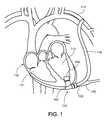
- FIG. 1illustrates a blood pump assembly implanted at a heart.
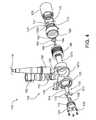
- FIG. 2is a perspective view of a blood pump of the blood pump assembly.
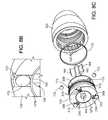
- FIG. 3Ais an exploded cutaway view of the blood pump.
- FIG. 3Bis an exploded perspective view of various components of the blood pump.
- FIG. 4is an exploded view of the blood pump.
- FIG. 5Ais a perspective view of a hub of the blood pump.
- FIG. 5Bis an axial view of the hub.
- FIG. 5Cis a cross-sectional view of the hub taken at line 5 C- 5 C of FIG. 5B .
- FIGS. 6A-6Dare meridional views of alternative blades for the hub.
- FIGS. 7A-7Bare meridional views of alternative blades and alternative bearing components for the hub.
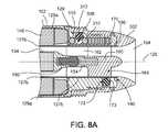
- FIG. 8Ais a cross-sectional view of an inlet end of a blood pump taken at line 8 A- 8 A of FIG. 2 .
- FIG. 8Bis a cutaway perspective view of an upstream stator and a housing of the blood pump of FIG. 8A .
- FIG. 8Cis an exploded view of the inlet end of the blood pump of FIG. 8A .
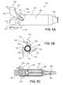
- FIG. 9is a cutaway perspective view of a connector for a driveline of a blood pump.
- FIG. 10is a schematic diagram that illustrates a drive system for a blood pump.
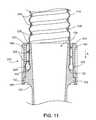
- FIG. 11is a cutaway view of a graft assembly.
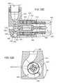
- FIG. 12Ais a perspective view of an alternative blood pump.
- FIG. 12Bis a diagram illustrating a rotor and fluid flow path of the blood pump of FIG. 12A .
- FIGS. 12C and 12Dare cross-sectional views of the blood pump of FIG. 12A .
- FIG. 13Ais a side view of a rotor and bearing assembly of the blood pump of FIG. 12A .
- FIG. 13Bis a perspective view of the rotor of the blood pump of FIG. 12A .
- FIG. 13Cis a front view of the rotor of FIG. 13B .
- FIG. 13Dis a back view of the rotor of FIG. 13B .
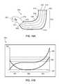
- FIG. 14Ais a meridional view of an example of a blade.
- FIG. 14Bis a graph illustrating characteristics of an inner edge the blade of FIG. 14A .
- FIG. 14Cis a graph illustrating characteristics of an outer edge of the blade of FIG. 14A .
- an example blood pump 100can be implanted in a patient's body to supplement, or in some cases replace, the natural pumping function of a heart 112 .
- the blood pump 100includes a housing 102 defining an inlet 104 , an outlet 106 , and an inner flow path between the inlet 104 and the outlet 106 .
- a rotating hub (not shown) containing a magnetic materialis positioned in the flow path within the housing 102 and includes a plurality of blades that provide mixed axial and centrifugal flow of fluid through the flow path.
- the inlet 104can be connected, for example, to a left ventricle 110 of the heart 112 and the outlet 106 can be connected, for example, to the subclavian artery 114 via a conduit 116 .
- the blood pump 100can connect to a percutaneous lead 118 that encloses a plurality of conductors, as described further below, for receiving electrical energy from a controller (not shown) that can be located outside of the patient's body.
- the blood pump 100can also be implanted such that the inlet 104 receives blood from a right ventricle 111 of the heart 112 and supplies blood to, for example, a pulmonary artery.
- the blood pump 100is commonly configured to provide partial support or full support to a left ventricle 110 or a right ventricle 111 .
- the blood pump 100is configured for biventricular support alone, or with a second blood pump 100 or a blood pump of another type.
- the blood pump 100is designed to provide general mechanical circulatory support and thus can supplement either systemic or pulmonary support.
- the blood pump 100can also be used to move blood from the left or right atrium or an arterial or venous vessel or any other vasculature to a different target vasculature that may include any arterial or venous vessel or organ.
- the pump 100can include other features such as those described in U.S. Provisional Application Ser. No. 61/392,811, filed Oct. 13, 2010, and titled “Pumping Blood,” U.S. Provisional Application Ser. No. 61/393,241, filed Oct. 14, 2010, and titled “Pumping Blood,” and U.S. application Ser. No. 13/273,185, filed Oct. 13, 2011, and titled “Pumping Blood,” the entire contents of which are incorporated herein by reference.
- FIGS. 2-4illustrate the physical structure of the blood pump 100 from different perspectives.
- FIG. 2illustrates the external structure of the blood pump 100 .
- the blood pump 100has a housing 102 that can be made of titanium or another biocompatible material and can be metal or nonmetal. On the interior and exterior of the housing 102 , all of or portions of metallic surfaces that come in contact with fluid can be subject to surface treatments. For example, the surface can be textured, sintered, beaded, or the like to promote the formation of a thin biological coating such as endothelial growth to discourage thrombogenesis.
- the housing 102includes a downstream component 125 , a body component 127 , a stator cover 129 , and an inlet cap 128 . Together, the downstream component 125 and the body component 127 define the outlet 106 and a port 122 that connects to the percutaneous lead 118 (shown in FIG. 1 ). The downstream component 125 and the body component 127 also define an annular channel 144 . The downstream component 125 includes a removable back plate or plug 124 , which can be secured over an opening in the downstream component 125 by screws 126 .
- the motor stator 146is disposed within the housing 102 , which also defines the blood flow path 108 .
- the body component 127 and the downstream component 125 of the housing 102together define the outlet 106 of the blood pump 100 at an orientation off the inlet axis 120 .
- an outlet axis 121 defined centrally through the outlet 106is oriented generally orthogonal to the inlet axis 120 .
- the outlet axis 121is also laterally spaced from the inlet axis 120 by a distance, S, such that the axes 120 , 121 do not intersect.
- the back plate 124 and configuration of the outlet 106advantageously provide improved access to the downstream pump components.
- the back plate 124improves ease of installing components within the housing 102 during manufacturing and provides an ability to vary tolerances or fine adjustment of parts internal to the blood pump 100 .
- the outlet 106may include features such as threads or other mechanism to enhance interchangeability with different outflow conduits (not shown).
- outflow conduitsmay vary in size, shape, or material depending on the anatomical characteristics and the tissue composition of a target vasculature, and how the outflow conduit is designed to couple with the target vasculature. Ease of interchangeability promotes ease of use in an operation room and increases versatility of the blood pump 100 .
- the port 122is designed to receive a percutaneous lead that is intended to provide power and/or control signals to operate the blood pump 100 .
- the body component 127includes an outer portion 127 a that couples with the downstream component 125 or cover and an inner tubular portion 127 b with an inner surface that defines an inlet bore 162 where a rotor 133 and an upstream stator 160 are located.
- a motor stator 146 for driving the rotor 133( FIG. 3A ) resides about the outer surface of the inner tubular portion 127 b between the outer portion 127 a of the body component 127 and the inner tubular portion 127 b of the body component 127 .
- the motor stator 146is partially covered by the outer portion 127 a of the body component 127 and the stator cover 129 as shown.
- the stator cover 129has a visible portion 129 a that partially covers the motor stator 146 and further wraps over the inner tubular portion 127 b .
- a hidden portion 129 b of the stator cover 129receives the inlet cap 128 .
- stator cover 129wraps around part of the motor stator 146 and around the inner tubular portion 127 b .
- the inlet cap 128is secured directly over the hidden portion 129 b of the stator cover 129 , which can include threads 131 and additional locking features located inside radial holes 308 .
- the hidden portion 129 b of the stator cover 129further includes plug holes 173 that are intended to receive a press-fit feature such as a spherical structure (not shown) that directly presses over the wall of the inner tubular portion 127 b in securing stator blades 164 that functions to suspend and hold the rotor 133 in place (see FIG. 3A ).
- Both the stator blades 164 and the rotor 133are disposed within the inlet bore 162 and within the flow path 108 proximate an upstream end region 136 of the hub 134 .
- FIG. 3Awhich illustrates a cross-sectional view of the pump 100
- the body component 127 and the stator cover 129are joined by circumferential welds 190 between the inner tubular portion 127 b and the hidden portion 129 b of the stator cover 129 , and by circumferential welds 191 between the outer portion 127 a of the body component 127 and the visible portion 129 a of the stator cover 129 to define an annular compartment 148 .
- the motor stator 146is disposed within the compartment 148 partially covered by the outer portion 127 a of the body component 127 and partially covered by the visible portion 129 a of the stator cover 129 .
- the inner surface of the inlet cap 128joins seamlessly with the inner tube portion 127 b at the upstream end of the pump to define the inlet 104 .
- Inlet caps of different shapes, materials, and texturescan be selected for use at particular implantation locations.
- the rotor 133is mechanically suspended within the housing 102 by bearings at an upstream end region 133 a and a downstream end region 133 b .
- the rotor 133includes a fore or upstream bearing component 150 that rotates relative to a stator bearing component 154 coupled to the upstream stator 160 .
- the implementation as shownillustrates the ball component 150 on the rotor 133 and the cup component 154 on the stator 160 , but the reverse is also possible. Different materials can be selected for the ball and cup components of the bearing assembly based on the material hardness and the wear of the material upon use.
- the upstream stator blades 160 and the stator bearing component 154can be formed as an integral component or as separate components.
- the rotor 133includes an aft or downstream bearing component 152 that rotates relative to a housing bearing component 156 .
- the ball and cup like componentsshown with the ball component 150 on the back plate 124 and the cup component 154 on the downstream portion 133 b of the rotor 133 , can be reversed.
- the housing bearing component 156is directly coupled to the housing 102 , for example, on the back plate 124 .
- the shapes and sizes of the bearing components 150 , 152 , 154 , 156can be selected to suit a particular implementation.
- the housing bearing component 156can include a generally convex surface
- the downstream bearing component 152can include a matching concave surface.
- the stator bearing component 154can include a generally concave surface
- the upstream bearing component 150can include a matching convex surface.
- a small gape.g., approximately between about 0.0001 inches to about 0.0006 inches
- proximate bearing componentse.g., between the bearing components 150 , 154 and between the bearing components 152 , 156 .
- the total gap size between the upstream and downstream bearing gapsis approximately 0.0002 inches.
- the blood pump 100is configured to provide partial or full support to a patient's circulatory system.
- the blood pump 100includes a rotor 133 that moves blood along a flow path 108 from the inlet 104 to the outlet 106 .
- the rotor 133includes a hub 134 that has an axis of rotation, such as an inlet axis 120 , and a generally cylindrical shape along the length of the rotor 133 .
- the hub 134has an upstream end region 136 , a central region 138 , and a downstream end region 140 .
- the hub 134includes a magnetic material (not shown).
- the blood pump 100includes blades 142 for promoting flow. The blades 142 are positioned along a blade region of the hub 134 of the rotor 133 .
- blades 142are disposed on the downstream end region 140 of the hub 134 , e.g., located distally past a midpoint of the hub 134 or downstream of the central region 138 of the hub 134 . In the illustrated implementation, blades 142 extend downstream of the body of the hub 134 past the downstream end region 140 of the hub 134 . In various implementations, including the one as shown, the upstream end region 136 and the central region 138 of the hub 134 are devoid of any blades. In other implementations, the blades 142 may begin at or slightly distal of the midpoint of the hub 134 and extend along all or a part of the end region 136 and/or central region 138 while the upstream end region 136 is devoid of any blades. Incorporating a radial flow configuration allows the elimination of an aft stator, thus allowing surface area reduction as well as avoiding additional higher shear regions that typically occur at the stator blade leading edges.
- the rotor 133includes three blades 142 spaced approximately 60 degrees apart.
- Other implementationscan include, for example, as few as one blade 142 or up to ten blades 142 or more.
- the blades 142are circumferentially spaced apart at the same axial location, in this example, the spacing is equal between all blades 142 .
- Each blade 142has approximately the same length and geometry or curvature.
- a bladecan shape like a “J” but with the bottom portion of the “J” twisted at an angle. For instance, this wrap angle can range approximately from about 60 degrees to about 270 degrees.
- each blade 142can have a constant width along the entire length of the blade 142 , or have a varying with along its length.
- each blade 142has a curvature that extends downstream and flares radially outward (consequent of the “J” shape and wrap angle) such that a free end 167 of the blade 142 is at a radial distance much larger than the width of the blade 142 .
- the configuration of blades 142 illustratedcan provide both axial and centrifugal flow.
- a blade that extends downstream where the curvature does not flare radially outward, or simply follows the circumference of the rotor 133would generate an axial flow component and much less of a centrifugal component.
- the blades 142draw fluid through the inlet 104 , generating a generally axial flow along the inlet axis 120 .
- a portion of each blade 142extends into an annular channel 144 defined by a housing 102 of the blood pump 100 .
- the volute or annular channel 144is located about the inlet axis 120 and is in fluid communication with the outlet 106 .
- the volute or annular channel 144can have a spiral shape, and can have a cross-sectional area that increases along the flow path to assist in converting kinetic energy to pressure at the outlet 106 .
- the blades 142produce a generally centrifugal flow within the volute or annular channel 144 , causing fluid to flow through the outlet 106 .
- the blades 142move fluid within the housing 102 to impart energy to the fluid, in order to create a desired head pressure at the outlet 106 .
- the blades 142act to maintain or increase pressure at the outlet 106 by imparting kinetic energy. While velocity of the fluid may be different at various localized regions within the flow path 108 , the effect of the blades 142 is to maintain or increase pressure at the outlet 106 , as well as to promote fluid flow through the outlet 106 .
- the axial velocity of fluid through the pump 100is substantially constant over the hub 134 .
- Rotation of the rotor 133is driven by the motor stator 146 located about the hub 134 .
- Electrical currentflows through wire windings of the motor stator 146 to produce varying magnetic fields.
- the magnetic fieldsinteract with the magnetic material of the hub 134 to cause rotation of the rotor 133 .
- Wiring used in the motor stator 146can be any highly conductive material, including but not limited to copper, silver, or other materials.
- the motor stator 146is entirely hermetically sealed in the pump housing 102 , just like the magnetic material is hermetically encapsulated and sealed in or on the hub 134 .
- the magnetic materialcan be located anywhere in or on the hub 134 and may be present as one or multiple parts.
- the rotor materialmay also be fabricated from magnetic materials.
- the motor stator 146includes three wire windings that are positioned, for example, 120 degrees apart to form a three-phase motor stator.
- Other winding configurationscan alternatively be used, including configurations that include more than or fewer than three phases.
- each blade 142attach to the downstream end region 140 of the hub 134 .
- Each blade 142includes a leading edge 174 , a trailing edge 176 , and a body 178 .
- the body 178 of each blade 142extends downstream of the hub 134 and extends radially outward within the annular channel 144 ( FIG. 3 ).
- the blades 142are sized and shaped to impart kinetic energy to the fluid flow. For example, as the rotor 133 rotates, the blade 142 draws the fluid and moves the fluid along the length of the blade 142 . As each blade 142 curves downstream, the fluid is moved in the direction from upstream to downstream. Since the blade 142 also extends and flares radially outward, the rotational component of velocity is further increased downstream.
- the exemplary bladeis shaped and dimensioned to optimize flow from the inlet to the outlet while creating a desired head pressure.
- an upstream portion 175 of the blade 142 proximate the hub 134generally provides an axial component of fluid flow where the blade portion 175 generally extends in an axial direction downstream, and a downstream portion 177 of the blade 142 , positioned in the annular channel 144 , provides a radial component of fluid flow where the blade portion 177 generally extends in a radial direction away from the hub 134 .
- a configuration of blades 142 on the hub 134 that creates both axial and radial (centrifugal) flow along the flow path 108generally limits undesired secondary flow paths within the flow path 108 and can allow, for example, direct washing of many or all surfaces within the blood pump 100 .
- the desired rotation of the hub 134is produced by the interaction of magnetic fields generated by the motor stator 146 with a magnetic material 180 hermetically enclosed within the hub 134 .
- FIGS. 6A-6Dillustrate various alternative blade, or vane, configurations for use with the pump assembly described above.
- Alternative blades 142 a - 142 dcan be located near the downstream end region 140 of the hub 134 . Each configuration extends downstream past an end of the hub 134 which is defined by the downstream bearing assembly components 152 , 156 .
- the illustrationsshow that each blade 142 a - 142 d extends from, or cantilevers off, the rotor 133 .
- One end 165 of each blade 142 a - 142 dis anchored to the hub 134 and the remainder of the blade 142 a - 142 d extends into the flow path, for example, with a free end 167 extending to, near, or into a volute.
- Each blade 142 a - 142 dextends from the hub 134 from a location over the upstream end of the downstream bearing component 152 .
- the blade 142 a - 142 dextends from or cantilevers off other portions of the rotor, such as an edge of the hub 134 or a downstream end of the bearing component 152 on the rotor 133 .
- the blades 142 a - 142 dcan have different leading edge shapes and can define gaps of different sizes and shapes, relative to the hub 134 and the axis of rotation near the downstream bearing components 152 , 156 .
- the different blades 142 a - 142 dcan be designed to facilitate washing of gaps between and/or around the downstream bearing components 152 , 156 .
- the shape of the blades 142may be designed to reduce energy dissipation in the fluid. Additionally, or alternatively, the configuration of blades 142 can be selected to reduce localized mechanical stress at the downstream end region 140 where the blades 142 attach to the hub 134 , or to provide modified flow paths over the leading edge 174 .
- a blade 142 ahas a leading edge 174 a that is substantially orthogonal to the inlet axis 120 .
- a generally small and constant gap 182 aranging from approximately 0.0001 inch to approximately 0.007 inch is maintained along the entirely length of the blade 142 a on both sides between an outer edge 185 a of blade 142 a and an inner surface of the housing 102 (e.g., as defined by body component 127 ) and an inner edge 184 a of blade 142 a and another inner surface of the housing 102 (e.g., as defined by downstream component 125 ), where the downstream bearing component 156 is located.
- Some implementationshave about a 0.003 inch gap clearance. Efficiency of the blades moving fluids generally improves as the gap distance decreases between blades and housing inner walls.
- FIG. 6Bshows a blade 142 b having a similar configuration as in FIG. 6A except for a gap 182 b , for example a concave gap, created downstream of the hub 134 between the inner edge 184 b of the blade 142 b and the downstream bearing components 152 , 156 .
- the gap 182is defined by a cutaway portion of the blade 142 b adjacent the downstream bearing assembly components 152 , 156 .
- the gap 182 bleads to increased blood flow in the void between the blade 142 b and the bearing assembly components 152 , 156 , which promotes washing of and heat transfer from surfaces of the bearing components.
- the gap 182 bis created by cutting an area from the blade 142 b in a gradually curving manner resulting in a curvature on the blade 142 b having a smaller radius that continues to a larger radius moving downstream away from the bearing assembly.
- the largest distance in this gap 182 branges from approximately 0.010 inches to approximately 0.040 inches and gradually decreases to a similar range of gap distances as disclosed in FIG. 6A downstream a length of the blade 142 b.
- FIGS. 6C-6Dillustrate other modifications to the upstream portion of the blades.
- a blade 142 cis supported by a strut-like region that provides the leading edge 174 c .
- the resulting cutaway portionsdefine a gap 182 c with a distance, for example, ranging from approximately 0.02 inches to approximately 0.06 inches, between the inner edge of the blade 184 c and the downstream bearing components 152 , 156 .
- a blade 142 dincludes a cutaway portion that defines a gap 182 d with a distance, for example, ranging from approximately 0.010 inches to approximately 0.040 inches, at its maximum, between the inner edge of the blade 184 d and the downstream bearing components 152 , 156 .
- the gap 182 dis created similarly to the one shown in FIG. 6B with a gradually changing curvature except that the starting radius of the curve near the bearing assembly is larger than the one in FIG. 6B and that the curve terminates slightly more upstream along the length of the blade.
- the blade 142 dincludes a swept leading edge 174 d relative to the incoming flow that is generally parallel to the inlet axis 120 .
- a swept leading edgeextends obliquely relative to the inlet axis 120 .
- Straight leading edgesmay also be employed.
- the sweep angle of the leading edgemay be used to control the flow acceleration and consequent shear in the region of the leading edge.
- the cutaway angle at the leading edges 174 c , 174 d of the blades 142 c and 142 dcan help to increase performance of the pump by reducing flow separation where the leading edge meets the fluid.
- An angled leading edgealso reduces shear forces.
- the leading edge of the bladecan take the form of a strut cantilevering off the downstream edge of the hub 134 at the bearing component 152 and extending downstream to form wide blades for moving fluid.
- leading edge of the blade 142can take on any shape/curvature, including but not limited to, straight orthogonal from the axis of rotation, straight at an angle from the axis of rotation, and having one or more curves extending in a downstream direction from the axis of rotation.
- straight orthogonal from the axis of rotationstraight at an angle from the axis of rotation
- curvesextending in a downstream direction from the axis of rotation.
- Several of these designsalter the vane leading edge or cutaway portions of the blade to accommodate bearing washing, modify the flow over the vane leading edges or to reduce localized stresses in the structure.
- FIGS. 6A-6Dillustrate several approaches for enhancing washing between the rotating hub and bearing assembly and the blade or vane.
- the designshave an increased gap that allows additional washing in this gap region as well as eliminates stress risers where the vane joins the rotor hub 134 .
- a strut extending from the rotor hub 134supports the blade positioned downstream.
- the general downstream position blade/vanesallow radial, mixed, or hybrid hydraulic configurations.
- a gapcan be created between the inner edge of the blade 142 and the bearing assembly by forming the inner edges of the blades with curves of varying or constant curvatures, which promotes flow at the inner edge of the blades to prevent thrombus formation and washing the bearing components.
- downstream bearing components 152 a , 156 acan be substantially equal to the diameter of a hub 134 a .
- a diameter of downstream bearing components 152 b , 156 bcan be smaller than a diameter of a corresponding hub 134 b .
- a trailing portion 186 of the hub 134 bincludes an axial taper directing downstream and toward the axis of rotation that terminates at a similar diameter as the bearing components 152 b , 156 b .
- the remaining downstream portion of the blade 142curves gradually and radially outwardly towards the free end 167 of the blade 142 along the inner surface of the pump housing 102 (e.g., defined by the downstream component).
- the diameter of downstream bearing componentscan be larger than that of a hub.
- the hubcan include a trailing portion that converges or diverges, respectively, to match the diameter of the bearing components and curvature as defined by the inner surface of the pump housing.
- the shape of the blade 142can vary to conform to the shape of the trailing portion of the hub, as shown in FIG. 7B .
- the design of the downstream bearing assembly sizecan be modified in combination with the vane/blade design to facilitate the hydraulic design to obtain the desired flow characteristics.
- a larger or smaller bearingrelative to the hub diameter and/or the upstream bearing diameter
- the upstream stator 160is positioned within the inlet bore 162 .
- the tubular portion 127 b or conduitwhich is part of the inner wall of the housing that defines the inlet bore 162 , is compressed at regions that correspond to blade locations of the upstream stator 160 . Compression of the tubular portion 127 b is achieved by inserting sealing elements 172 into plug holes 173 defined through the stator cover 129 and engaging the sealing elements with the tubular portion 127 b .
- Each sealing element 172is preferably of spherical or hemi-spherical shape, or an object that can both create a seal with no gap between the edge of the sealing element 172 and a circumferential wall of the plug hole and a force exerted against the stator blade 164 or other portions of the upstream stator 160 to secure the stator assembly in place.
- the positions of the plug holes 173correspond to locations of the stator blades 164 .
- the plug holes 173are defined over regions of the tubular portion 127 b that engage the ends of the stator blades 164 ( FIG. 8B ).
- An inlet cap, such as inlet cap 128 bis threaded over the stator cover 129 .
- the sealing elements 172are press-fit into the plug holes 173 . Friction between the sealing elements 172 and the walls of the plug holes 173 helps secure the sealing elements against the tubular portion 127 b , which in turn secures the upstream stator 160 by pressing against the stator blades 164 .
- the sealing elements 172can hermetically seal the plug holes 173 by, for example, expanding slightly when pressed against the tubular portion 127 b .
- the sealing elements 172can be made from any fluid-impermeable material and can be in the form of, for example, spherical plugs. Alternatively, the sealing elements 172 can have cylindrical, hemispherical, or other geometries.
- a ratchet mechanismlimits rotational movement of an inlet cap 302 relative to the stator cover 129 .
- the ratchet mechanismincludes limiting elements 312 that engage inner grooves 330 defined in the inner circumference of the inlet cap 302 .
- the limiting elements 312are partially disposed in radial holes 308 defined in the stator cover 129 .
- the radial holes 308extend only partially through the stator cover 129 .
- Resilient elements 310such as o-rings, are disposed in the holes 308 between the limiting elements 312 and the stator cover 129 .
- the resilient elements 310position the limiting elements 312 such that the limiting elements 312 protrude out of the holes 308 .
- the resilient elements 310also act as springs to counteract the radial force exerted by the inlet cap 302 so that the limiting elements 312 are frictionally engaged with the inlet cap 302 .
- the limiting elements 312enter and situate in the grooves 330 .
- the resilient elements 310exert a radial outward force on the limiting elements to limit rotation of the inlet cap 302 relative to the stator cover 129 .
- the inlet cap 302is threadedly screwed onto the stator cover 129 .
- each limiting element 312can be a spherical structure, or can have another other shape with a curved exposed surface that can engage with the grooves 330 .
- the combination of limiting and resilient elementscan be replaced by a spring-loaded plug with a protruding element for engaging with the grooves.
- the inner surface of the inlet cap 302may have a saw-like or other configuration that generates friction to prevent the inlet cap 302 from coming loose.
- a connector 280that can be used with the pump 100 is shown.
- the percutaneous lead 118 described abovehas two ends, one end that is coupled with the pump 100 and another end that couples directly or indirectly to a control system and/or power source.
- the connector 280 shown in FIG. 9can be configured for use at either end or both ends of the percutaneous lead 118 .
- the female portion (e.g., portion 192 of the connector 280 ) and male portion (e.g., portion 166 of the connector 280 )can be used interchangeably on any end of the percutaneous lead 118 , in the pump 100 , or on a control system and/or power source.
- the percutaneous lead 118terminates in a power lead 166 (e.g., female portion) that attaches to a corresponding power end connector 192 (e.g., male portion) located within the port 122 of the housing 102 ( FIG. 4 ).
- the power end connector 192encloses a plurality of conductors 194 that terminate in pins 196 .
- An insulation sleeve 198fits over the conductors 194 to create a hermetic seal around the pins 196 .
- the power end connector 192can be formed as part of the housing 102 or can be formed separately and attached to the housing 102 by, for example, snap fit.
- a mating region 200contains the pins 196 and is hermetically isolated from the inner portions of the housing 102 .
- the power lead 166encloses multiple conductors 218 a , 218 b , 218 c , 220 ( FIG. 10 ) and can mechanically and electrically connect with the power end connector 192 .
- the conductors 218 a , 218 b , 218 c , 220extend through the percutaneous lead 118 to connect phase windings of the motor stator 146 to a pump controller 216 ( FIG. 10 ), as described further below.
- the power lead 166has a power lead mating region 202 that defines a plurality of openings 204 for receiving and electrically connecting to the pins 196 , and each opening 204 electrically connects to one of the conductors 218 a , 218 b , 218 c , 220 .
- the openings 204 of the power lead 166can be formed within a seal wiper 206 that can provide pin-to-pin isolation for making connections in a wet environment.
- the pin and opening configurationcan be reversed.
- the mating region 200can contain openings 204 formed with a seal wiper 206
- the power lead mating region 202can contain a plurality of pins 196 surrounded by the insulation sleeve 198 .
- the pins 196 and the corresponding openings 204 of the mating regions 200 , 202can be arranged in an equilateral triangular pattern.
- each pin 196 and opening 204can be placed at a vertex of an equilateral triangle.
- a fourth pin 196is included in the power end connector 192 and a fourth opening 204 is defined in the mating region 202 .
- the fourth pin 196 and fourth opening 204can be placed at the center of the triangular pattern, with the remaining pins 196 and openings 204 located at the vertices of the triangle, as described above.
- the fourth pin 196 and opening 204are connected to a common conductor of the three-phase motor, such as the additional conductor 220 as described further below, the rotational orientation of the two mating regions 200 , 202 relative to each other will not affect motor performance.
- a surgeoncan easily connect the power lead 166 to the power end connector 192 using an alignment in any of three positions.
- Mechanical latching between the power lead 166 and the power end connector 192can be achieved through tabs or tines 208 disposed circumferentially around the power lead 166 that snap into a groove 210 disposed circumferentially around the power end connector 192 .
- the mechanical latching featurescan be reversed. After the tines 208 couple to the groove 210 , an outer sleeve (not shown) slidably positioned over the power lead 166 can slide over the tines 208 to prevent the tines 208 from moving out of the groove 210 .
- the connector 280When the connector 280 is implanted into a patient, it must hermetically isolate the contacts from fluids in the body while providing appropriate pin to pin orientation and create a secure mechanical connection.
- Using a triangular clocking featureallows the connector 280 to be inserted at three different orientations 120 degrees apart. There is no concern for having a connection in a particular orientation because the connection is made to a three-phase motor. In other words, different orientations of connection are acceptable. As long as the phases are connected in the same order to the cable wires, the specific wire-to-wire connection is not important. Therefore, when the connector 280 is connected at each of the three different orientations, the order of the phases is not changed even though the individual wire-to-wire connections change.
- connectorstypically use a single clocking position so depending on the starting orientation, the connector must be rotated up to 360 degrees before the connection can be made.
- the triangular connectorrequires at most a 120 degree rotation to insert the connector. This facilitates the ease of use and reduces any potential twisting of the cable as a result of the connection.
- a similar triangular clockingcan be accomplished by positioning 6 pins in an equilateral triangular pattern.
- Alternate wiring approachescan also be configured with the triangular keying.
- One example of thisis for a 4 conductor connection involving a three phase motor (described below). For this case the phases are kept in the triangular pattern and the fourth connection is made through a central pin. In this case only the motor phase pins change with the different clocking and the central connection remains the same.
- a motor drive system 211includes phase windings for at least three phases.
- the motor drive system 211has a three-phase configuration for the motor stator 146 and has three phase windings 212 a , 212 b , 212 c that are placed 120 degrees apart about the inlet axis 120 .
- Each of the phase windings 212 a , 212 b , 212 chas a first end and a second end, and the second end of each phase winding 212 a , 212 b , 212 c is connected to a common loadable point 214 .
- the additional conductor 220can be a neutral connection but can also be driven independently through independent drive electronics.
- the percutaneous lead 118includes the set of conductors 218 a , 218 b , 218 c , 220 , including the first conductor 218 a for connecting the pump controller 216 and the first end of the first phase winding 212 a , the second conductor 218 b for connecting the pump controller 216 and the first end of the second phase winding 212 b , and the third conductor 218 c for connecting the pump controller 216 and the first end of the third phase winding 212 c .
- the set of conductorsincludes an additional conductor 220 for connecting the pump controller 216 and the common loadable point 214 .
- the pump controller 216is configured to independently control current in the first conductor 218 a , the second conductor 218 b , the third conductor 218 c , and the additional conductor 220 .
- the controller 216contains independent drive electronics for each of the three windings 212 a , 212 b , 212 c and for the additional conductor 220 and thus can independently control each phase of the motor stator winding. Because the additional conductor 220 can be driven independently of the conductors 218 a , 218 b , 218 c , the motor drive system 211 can be operated as a three-phase, two-phase, or a one-phase system.
- the pump 100can be operated even when faults are present in the drive electronics, the phase windings 212 a , 212 b , 212 c , and the conductors 218 a , 218 b , 218 c , 220 .
- the motor drive system 211can detect this fault condition then switch to a two-phase operation mode.
- the motor drive system 211can be operated in a one-phase mode.
- the motor drive system 211can be operated in three-phase mode. Finally, if a fault occurs in the additional conductor 220 and a fault occurs in one of the phase windings 212 a , the motor drive system 211 can be operated in single-phase mode.
- FIG. 11illustrates a graft assembly 222 for use with pump 100 .
- the graft assembly 222provides fluid communication from the outlet 106 of the pump 100 to a target vasculature, vessel, or organ in the circulatory system.
- the graft assembly 222includes a conduit 116 that defines a lumen 225 , a reinforcement component 226 about the conduit 116 , and a support structure 224 molded about the conduit 116 .
- the conduit 116can be formed of, for example, a woven material, for permitting the conduit 116 to be sewn to, for example, a blood vessel.
- the material of the conduitcan be a non-synthetic or synthetic material, including, but not limited to polytetrafluoroethylene (PTFE) and polyester fabric (e.g., Dacron).
- the reinforcement component 226such as a polymer monofilament or a wire, is helically wrapped about the conduit 116 to provide the conduit 116 with additional strength and to prevent kinking of the conduit when in use.
- the conduit 116has inherent resiliency such that it can return its standard or neutral shape after being twisted or subjected to a compression force.
- every region the graft assembly 222incorporates a slightly elastic or resilient property to resist kinking and compression.
- the support structure 224is molded about an end region 117 of the conduit 116 .
- the support structure 224may be rigid or flexible, but it is designed to anchor the conduit 116 over the external housing of the pump 100 or at the outlet 106 of the pump 100 .
- the reinforcement component 226can be embedded within the support structure 224 .
- the support structure 224has a lip or a flange 228 at an end that extends about the conduit 116 and laterally inward and outward from the conduit 116 to provide anchoring.
- the flange 228can enhance the sealing of the connection between the graft assembly 222 and the pump 100 as described further below.
- the graft assembly 222can engage exterior housing features of the pump 100 to attach and seal around the outlet 106 .
- the exterior of the housing 102includes a recessed portion 130 and a raised portion 132 that extend partially or completely about the outlet 106 .
- the conduit 116can slide over the outlet 106 in the direction of arrow A until the flange 228 reaches the recessed portion 130 and the support structure 224 engages the raised portion 132 , limiting further motion toward the pump 100 .
- the fitting 168can be, for example, pulled over the molded support structure 224 in the direction of arrow A such that a portion 169 of the fitting 168 snaps over and couples with the raised portion 132 of the outlet 106 .
- the fitting 168compresses the flange 228 into the recessed portion 130 , forming a seal around the outlet 106 .
- the recessed portion 130can be omitted.
- an inner portion of the fitting 168can be threaded to engage external threads (not shown) of the housing 102 that are located about the outlet 106 . Screwing the fitting over the support structure 224 and the external threads compresses the flange 228 to form a seal about the outlet 106 .
- the fitting 168is formed of two semi-cylindrical pieces that fit over the conduit 116 and a portion of the housing 102 to capture the support structure 224 and compress the flange 228 to form a seal. The two semi-cylindrical pieces can attach to each other via, for example, set screws.
- the lumen of the conduit 116has a same diameter as the edge of opening of the outlet 106 .
- the conduit of the lumenhas the same diameter as the opening of the outlet 106 .
- the outflow blood pathwould have a similar diameter from a region proximate the downstream bearing assembly through the conduit if the outlet 106 has a same diameter from a region proximate the downstream bearing assembly to the opening.
- the outflowcan also have a funnel or tapered lumen where if the opening of the outflow has a larger diameter relative to the region proximate the downstream bearing assembly.
- an alternative blood pump 400includes an alternative rotor 410 .
- the rotor 410rotates around an axis 411 , for example, in a counter clockwise direction, R, creating axial and radial (e.g., centrifugal) flows within a flow path 440 ( FIG. 12B ).
- the rotor 410is located in a housing 402 that has the same types of components as the housing 102 of the blood pump 100 (see FIGS. 2 , 3 A, 3 B, and 4 ). However, the housing 402 accommodates a rotor 410 different from the rotor 133 and the housing 402 defines a flow path 440 that is modified relative to the flow path 108 .
- the flow path 440fluid enters an inlet 404 and exits through an outlet 406 .
- the flow path 440includes a channel 442 , a tapered region 444 , and a volute 446 .
- the channel 442is generally cylindrical and surrounds an upstream stator 460 and upstream portions of the rotor 410 .
- the channel 442has a substantially constant diameter that extends from the upstream stator 460 along at least half of the rotor 410 .
- the diameter of the flow path 440then decreases in the tapered region 444 , which is located around a downstream end of the rotor 410 .
- the narrowest outer diameter of the flow path 440 along the axis 411occurs at the end of the tapered region 444 .
- the volute 446is located downstream of the tapered region 444 .
- the housing 402defines the flow path 440 with inner walls 450 , 451 , 452 , 453 .
- a cylindrical inner wall 450defines the channel 442
- inward flaring wall 451decreases the diameter of the flow path 440 in the tapered region 444 .
- Circumferential walls 452define an annular channel leading to the volute 446 , providing a desired amount of clearance between the outer edges of the blades 430 .
- the walls 452are dimensioned to provide a consistent clearance around the blades 430 except at a free end of each blade 430 that extends into the volute 446 .
- Walls 453define the volute 446 , including an outer ring 455 that has expanding cross-sectional area along the direction of rotation, R.
- the volute 446includes a spiral region that extends around the axis 411 , centered on (e.g., located generally symmetrically about) a plane generally perpendicular the axis 411 .
- the volute 446expands along the direction of rotation, R, providing an increasing distance, D, from the end of blades 430 on the rotor 410 and an increasing width, W, measured parallel to the axis 411 (see FIG. 12B ).
- the rotor 410includes a hub 412 , an upstream bearing component 414 , and a downstream bearing component 416 .
- the outer diameter of the upstream bearing component 414 and the downstream bearing component 416are approximately equal.
- the hub 412increases to a maximum outer diameter, remains constant at the maximum outer diameter in a central region 422 , and then decreases.
- the hub 412includes a tapered region 420 at a fore or proximal end 413 of the hub 412 , adjacent the upstream bearing component 414 .
- the outer diameter of the hub 412increases gradually to reach a maximum outer diameter of the hub 412 .
- the hub 412Adjacent the tapered region 420 , the hub 412 includes the central region 422 , in which the outer diameter of the hub 412 is cylindrical or substantially constant.
- the hub 412Adjacent the central region 422 , the hub 412 also includes a tapered region 424 at an aft or distal end 415 of the hub 412 in which the outer diameter of the hub 412 decreases from the maximum outer diameter of the hub 412 to the outer diameter of the downstream bearing component 416 .
- the change in diameter of the hub 412occurs more steeply in the tapered region 424 than in the tapered region 420 .
- the tapered region 424may be two thirds or less of the length of the tapered region 420 along the axis 411 .
- the rotor 410includes four blades 430 , which extend from the tapered region 424 at the distal end 415 of the hub 412 .
- the blades 430are spaced apart equally around the circumference of the hub 412 , for example, approximately 90 degrees apart around the axis 411 .
- Each blade 430includes a fixed end 432 that is anchored to the hub 412 in the decreasing tapered region 424 , for example, at an aft-facing surface 425 of the hub 412 .
- the blades 430connect differently from the blades 142 of the rotor 133 , since the blades 142 extend from the hub 134 from a connection at the largest outer diameter of the hub 134 (see FIG. 5A ).
- connection of the forward leading edge of exemplary blade 430 at the aft-facing surface 425is the only connection between the blade 430 and the rotor 410 .
- the blades 430connect to the aft-facing surface 425 at an inflection region where the aft-facing surface 425 transitions from an increasing rate of change of the outer diameter of the hub 412 to a decreasing rate of change of the outer diameter of the hub 412 .
- Each blade 430cantilevers or projects from the hub 412 and terminates in a free end 434 that extends into the volute 446 .
- the free end 434can include a generally linear trailing edge that extends in a direction that is substantially parallel to the axis 411 .
- Each blade 430extends distally beyond the distal end 415 of the hub 412 and past the downstream bearing component 416 , with each blade 430 twisting along its length. No blades are disposed on or are located around the tapered region 420 or the central region 422 of the hub 412 .
- Each blade 430extends circumferentially around the axis 411 by approximately 90 to 110 degrees.
- Each blade 430includes an inner edge 445 that has a portion that faces generally inward toward the axis 411 and a portion that faces generally in an aft direction.
- Each blade 430also includes an outer edge 448 that has a portion that faces generally outward toward the walls 451 , 452 of the pump housing 402 , having a portion that faces generally outward from the axis 411 and a portion that faces generally forward, toward the inlet 404 .
- Each blade 430includes, at the fixed end 432 , a leading edge 431 that is angled with respect to the axis 411 .
- the leading edge 431can extend linearly at an angle between approximately 30 degrees and approximately 60 degrees, or at an angle of 45 degrees.
- the leading edge 431terminates at a distance from the axis 411 that is approximately equal to the maximum outer diameter of the hub 412 .
- the distance that the leading edge 431 extendsmay vary according to the amount of space provided by the inner walls 451 , 452 of the housing 402 .
- each blade 430has a leading portion or upstream portion 436 proximate the hub 412 that includes a concave surface 437 that imparts energy to fluid flowing in the axial direction.
- Each blade 430also includes a downstream region 438 that includes a convex surface 439 that imparts energy to the flow flowing in primarily a radially outward or centrifugal direction.
- the downstream region 438is generally surrounded by the volute 446 . Fluid drawn axially by the concave surface 437 is accelerated and flung outward along the convex surface 439 into the volute 446 .
- Each blade 430includes an inner edge that faces toward the axis 411 .
- the inner edge 462defines a notch or concave gap 464 , or other region that curves away from the axis 411 .
- the concave gap 464can be located over or upstream of the downstream bearing component 416 .
- the concave gap 464increases flow to promote washing of the downstream bearing. In some implementations, the narrowest portion of the face of the blade 430 occurs at the location of the concave gap 464 .
- the blades 430 of the rotor 410project generally radially outward from the hub or axis of rotation. As shown in FIG. 13A , for example, the radial length of each blade 430 is significantly greater than the axial length of the blade 430 . By contrast, the blades 142 of exemplary rotor 133 have a generally longer axial length. In various embodiments, an axial length 441 of the blade section is greater than the diameter 443 of the blade section. In other words, the blades 430 may be shaped and configured to project distally in a fin-like configuration. In various embodiments, the axial length 441 of the blade section is less than the diameter 443 of the blade section. In the exemplary embodiment of FIG. 13A , the leading edge 431 extends from the aft of the hub 412 in an axial direction. The trailing edge 435 has a chamfer shape at its start point and thereafter generally extends in a predominantly radial direction.
- the profile of the hub 412covers the upstream portion 436 of each blade 430 , which includes the fixed ends 432 of the blades 430 and substantially all of the twisting along the blades 430 .
- the axial flow components imparted by the blades 430are generated in a cylindrical region with an outer diameter no greater than the outer diameter of the hub 412 .
- the upstream portions 436 of the blades 430are located in a narrowed region of the flow path 440 , for example, after the inner diameter of the housing 402 decreases along the walls 451 , which may be the narrowest inner diameter about the axis 411 .
- fluid flow to the upstream portions 436can have a higher velocity than fluid flow through upstream regions of the flow path 440 .
- the higher velocity in this narrowed flow region, together with the rotation of the leading portions of the blades,can provide strong washing currents.
- This regioncan be located over the downstream bearing component 416 and other downstream bearing components (see FIG. 12C ) to reduce the risk of thrombogenesis.
- the downstream regions 438extend radially outward from the axis 411 beyond the maximum outer diameter of the hub 412 .
- the downstream regions 438are aligned substantially parallel to the axis 411 .
- axial fluid flow along the rotor 410is substantially constant when the pump 400 is in operation. Blood has a very low compressibility, and may be considered incompressible. Where no energy is added to the flow, and energy in the flow remains generally constant, velocity of the flow tends to be inversely proportional to pressure upstream of the blades 430 due to changes in the outer diameter of the flow path 440 .
- the tapered region 444 of the flow path 440in which the flow channel narrows over the downstream end of the hub 412 (e.g., over the tapered region 424 of the hub 412 ), is intended to increase velocity of the flow.
- the decrease in pressure in the tapered region 444is localized and relatively small. Further, the effect of the localized decrease in pressure is reduced because the tapered region 444 occurs proximate (e.g., adjacent to) the blades 430 .
- the blades 430impart energy to the fluid and thus increase pressure. For example, in the region of the flow path 440 in which the blades 430 are disposed, the blades 430 move the fluid from one point to another, imparting kinetic energy which increases pressure.
- FIG. 14Aa meridional view of an example of a blade 500 is shown.
- the viewrepresents features along a path defined by an axisymmetric stream surface through the center of the blade 500 .
- the blade 500may be disposed on a hub and positioned within a housing as described above.
- the blade 500has the same general shape as the blade 430 described above. Flow over the blade 500 occurs in the general direction of arrow F.
- the blade 500has a fixed end 502 disposed on the hub, and a free end 504 that extends toward a volute. In some implementations, the free end 504 extends to or into the volute.
- the fixed end 502can be formed as strut or other feature, and includes a leading edge 512 and a rear edge 513 .
- the blade 500also has an inner edge 514 , an outer edge 516 , and a trailing edge 518 .
- the inner edge 514faces generally inward toward the axis of rotation of the hub, for example, facing in toward the axis of rotation and in an aft or downstream direction.
- the outer edge 516faces generally outward from the axis of rotation, for example, having regions that face outward toward inner walls of the pump housing that define the flow path.
- the pump housingdefines a shroud or sheath circumferentially around the outer edge 516 , defining a desired clearance around the outer edge 516 .
- An aft wall of the pump housingmay define clearance with a generally aft-facing portion 515 of the inner edge 514 .
- the trailing edge 518faces and/or enters the volute, is generally linear, and may be chamfered or tapered. Due to twisting of the blade 500 along its length, the wrap angles and blade angles defined by the blade 500 are different at the inner edge 514 and outer edge 516 , as described below.
- a graph 550illustrates characteristics of the blade 500 along the inner edge 514 .
- a blade angle curve 556indicates changes of the blade angle along the inner edge 514
- a wrap angle curve 558indicates the extent that the blade 500 extends circumferentially about the axis of rotation along the inner edge 514 .
- the horizontal axis 551 of the graph 550indicates a normalized distance along the inner edge 514 .
- the left side of the graph 550represents the beginning of the inner edge 514 , at position 552 in FIG. 14A , for example, adjacent the rear edge 513 .
- the right side of the graph 550represents the end of the inner edge 514 , at position 553 of FIG. 14A , for example, adjacent the trailing edge 518 .
- the vertical axis 554indicates angle values, beginning at zero degrees and increasing up the vertical axis 554 .
- the wrap angleis defined as an angle that the blade 500 extends circumferentially around the axis of rotation. As indicated by the wrap angle curve 558 , the wrap angle is defined to be zero degrees at the position 552 , which is beginning or leading point of the inner edge 514 . Along an initial region 561 , which can be approximately the initial one quarter to one third of the length of the inner edge 514 , the wrap angle increases. The wrap angle has a decreasing rate of change in the initial region 561 . Along a central region 562 , which can be approximately the central one third of length of the inner edge 514 , the wrap angle remains generally constant. For example, the wrap angle varies within a range of 10 degrees, or within a range of 5 degrees, or less along the central region.
- the wrap angleincreases with an increasing rate of change.
- the maximum wrap angleis approximately 100 degrees at the position 553 at the trailing edge 518 (indicated at the right edge of the graph 550 ).
- the maximum wrap anglemay be between 85 degrees and 115 degrees, or between 90 degrees and 110 degrees, etc.
- the magnitude of the rate of change of the slope of wrap angle curve 558e.g., the magnitude of the increase or decrease of the rate of change of the wrap angle
- the initial region 561 and along the end region 563are approximately equal.
- the blade angleis defined as an angle between the blade and the axis of rotation, represented on the graph 550 by the blade angle curve 556 . From an initial blade angle value, the blade angle decreases along an initial portion of the inner edge 514 , until approximately one third to one half of the length of the inner edge 514 . Thereafter, the blade angle increases, ending at a blade angle equal to or greater than the initial blade angle.
- the blade angle curve 556has a continuously increasing slope, indicating that the rate of change of the blade angle increases along substantially the entire inner edge 514 .
- the rate of change of the blade angle(e.g., slope of the blade angle curve 556 ) increases at a generally constant rate.
- the blade anglevaries by at least 30 degrees, at least 40 degrees, at least 50 degrees, or more along the length of the inner edge 514 .
- the lowest value of the blade angle along the inner edge 514occurs at a position between approximately one third and one half of the length of the inner edge 514 .
- the final blade angle along the inner edge 514(e.g., at position 553 , corresponding to the right side of the graph 550 ) is greater than the initial blade angle along the inner edge 514 (e.g., at position 552 , corresponding to the left side of the graph 550 ).
- the final blade angle and the initial blade anglecan be within approximately 30 degrees, 20 degrees, or 10 degrees of each other.
- a graph 570illustrates characteristics of the blade 500 along the outer edge 516 .
- a blade angle curve 576indicates changes of the blade angle along the outer edge 516
- a wrap angle curve 578indicates the extent that the blade 500 extends circumferentially about the axis of rotation along the outer edge 516 .
- the horizontal axis 571 of the graph 570indicates a normalized distance along the outer edge 516 .
- the left side of the graph 550represents the beginning of the outer edge 516 , at position 572 in FIG. 14A , for example, adjacent the leading edge 512 .
- the right side of the graph 570represents the end of the outer edge 516 , at position 573 of FIG. 14A , for example, adjacent the trailing edge 518 .
- the vertical axis 574indicates angle values, beginning at zero degrees and increasing up the vertical axis 574 .
- the wrap angleis defined as an angle that the blade 500 extends circumferentially around the axis of rotation, as noted above. As indicated by the wrap angle curve 578 , the wrap angle is defined to be zero degrees at the position 572 , which is beginning or leading point of the outer edge 516 . The wrap angle increases at a generally constant rate along the outer edge 516 , indicated by the generally linear trajectory of the wrap angle curve 578 . In some implementations, the final wrap angle (e.g., at the position 573 ) is approximately 100 degrees, for example, between 85 degrees and 115 degrees, or between 90 degrees and 110 degrees, etc.
- the blade angleis defined as an angle between the blade and the axis of rotation, represented on the graph 570 by the blade angle curve 576 . From an initial blade angle value, the blade angle decreases along an initial region 581 of the outer edge 516 . The initial region 581 may be approximately the initial one third to one half of the length of the outer edge 516 . The blade angle then increases along an end region 583 of the outer edge 516 . The end region 583 can be approximately the final one third to one half of the length of the outer edge 516 . In some implementations, the rate of change of the blade angle (e.g., slope of the blade angle curve 576 ) increases at a substantially constant rate along substantially the entire outer edge 516 .
- the blade anglevaries no more than approximately 20 degrees, or no more than approximately 10 degrees along the outer edge 516 .
- the initial blade angle (e.g., at the position 572 , corresponding to the left side of the graph 570 ) and the final blade angle along the outer edge 516 (e.g., at the position 573 , corresponding to the right side of the graph 570 )are approximately equal (e.g., within 10 degrees of each other, or within 5 degrees of each other).
- the lowest value of the blade angle along the outer edge 516may occur at approximately the midpoint 585 along the length of the outer edge 516 .
- the pumps described hereinproduce washing of downstream bearing components at lower flow rates than, for example, purely axial flow pumps. Appropriate washing at lower flow rates can be advantageous for lower levels of ventricular support, such as right ventricle support applications.
- Mixed axial and centrifugal flowmay also reduce shear rate at surfaces within the pumps, reducing hemolysis.
- the flow characteristicsmay reduce fluid residence times within the pumps and reduce recirculation zones within the pumps, which may result in improved efficiency and reduced risk of thrombogenesis.
Landscapes
- Engineering & Computer Science (AREA)
- Health & Medical Sciences (AREA)
- Heart & Thoracic Surgery (AREA)
- Mechanical Engineering (AREA)
- Cardiology (AREA)
- Public Health (AREA)
- Biomedical Technology (AREA)
- Veterinary Medicine (AREA)
- Life Sciences & Earth Sciences (AREA)
- Animal Behavior & Ethology (AREA)
- General Health & Medical Sciences (AREA)
- Anesthesiology (AREA)
- Hematology (AREA)
- General Engineering & Computer Science (AREA)
- Vascular Medicine (AREA)
- Physics & Mathematics (AREA)
- Geometry (AREA)
- Gastroenterology & Hepatology (AREA)
- Pulmonology (AREA)
- Oral & Maxillofacial Surgery (AREA)
- Transplantation (AREA)
- External Artificial Organs (AREA)
- Structures Of Non-Positive Displacement Pumps (AREA)
Abstract
Description
Claims (20)
Priority Applications (3)
| Application Number | Priority Date | Filing Date | Title |
|---|---|---|---|
| US13/650,874US8864643B2 (en) | 2011-10-13 | 2012-10-12 | Pump and method for mixed flow blood pumping |
| US14/489,041US9533082B2 (en) | 2011-10-13 | 2014-09-17 | Pump and method for mixed flow blood pumping |
| US15/359,231US10279093B2 (en) | 2011-10-13 | 2016-11-22 | Pump and method for mixed flow blood pumping |
Applications Claiming Priority (2)
| Application Number | Priority Date | Filing Date | Title |
|---|---|---|---|
| US201161547032P | 2011-10-13 | 2011-10-13 | |
| US13/650,874US8864643B2 (en) | 2011-10-13 | 2012-10-12 | Pump and method for mixed flow blood pumping |
Related Child Applications (1)
| Application Number | Title | Priority Date | Filing Date |
|---|---|---|---|
| US14/489,041ContinuationUS9533082B2 (en) | 2011-10-13 | 2014-09-17 | Pump and method for mixed flow blood pumping |
Publications (2)
| Publication Number | Publication Date |
|---|---|
| US20130096364A1 US20130096364A1 (en) | 2013-04-18 |
| US8864643B2true US8864643B2 (en) | 2014-10-21 |
Family
ID=48082524
Family Applications (3)
| Application Number | Title | Priority Date | Filing Date |
|---|---|---|---|
| US13/650,874Expired - Fee RelatedUS8864643B2 (en) | 2011-10-13 | 2012-10-12 | Pump and method for mixed flow blood pumping |
| US14/489,041Active2032-12-28US9533082B2 (en) | 2011-10-13 | 2014-09-17 | Pump and method for mixed flow blood pumping |
| US15/359,231Active2033-02-03US10279093B2 (en) | 2011-10-13 | 2016-11-22 | Pump and method for mixed flow blood pumping |
Family Applications After (2)
| Application Number | Title | Priority Date | Filing Date |
|---|---|---|---|
| US14/489,041Active2032-12-28US9533082B2 (en) | 2011-10-13 | 2014-09-17 | Pump and method for mixed flow blood pumping |
| US15/359,231Active2033-02-03US10279093B2 (en) | 2011-10-13 | 2016-11-22 | Pump and method for mixed flow blood pumping |
Country Status (3)
| Country | Link |
|---|---|
| US (3) | US8864643B2 (en) |
| DE (1) | DE112012004282T5 (en) |
| WO (1) | WO2013056131A1 (en) |
Cited By (40)
| Publication number | Priority date | Publication date | Assignee | Title |
|---|---|---|---|---|
| DE102014004121A1 (en)* | 2014-03-24 | 2015-09-24 | Heraeus Deutschland GmbH & Co. KG | Pump housing made of at least three different sinterable materials |
| US20160369813A1 (en)* | 2013-06-21 | 2016-12-22 | Heraeus Deutschland GmbH & Co. KG | Pump housing of two different sinterable materials |
| US20160369814A1 (en)* | 2013-06-21 | 2016-12-22 | Heraeus Deutschland GmbH & Co. KG | Pump housing with hard inner layer and weldable outer layer |
| US9533082B2 (en) | 2011-10-13 | 2017-01-03 | Thoratec Corporation | Pump and method for mixed flow blood pumping |
| WO2019139686A1 (en) | 2018-01-10 | 2019-07-18 | Tc1 Llc | Bearingless implantable blood pump |
| US10539140B2 (en) | 2013-06-21 | 2020-01-21 | Heraeus Deutschland GmbH & Co. KG | Pump housing of a magnetic and a non-magnetic material |
| EP3597231A1 (en) | 2018-07-17 | 2020-01-22 | Tc1 Llc | Systems and methods for inertial sensing for vad diagnostics and closed loop control |
| WO2020068333A1 (en) | 2018-09-25 | 2020-04-02 | Tc1 Llc | Adaptive speed control algorithms and controllers for optimizing flow in ventricular assist devices |
| US10660998B2 (en) | 2016-08-12 | 2020-05-26 | Tci Llc | Devices and methods for monitoring bearing and seal performance |
| US10724534B2 (en) | 2014-11-26 | 2020-07-28 | Tc1 Llc | Pump and method for mixed flow blood pumping |
| US10857273B2 (en) | 2016-07-21 | 2020-12-08 | Tc1 Llc | Rotary seal for cantilevered rotor pump and methods for axial flow blood pumping |
| US20220168556A1 (en)* | 2017-02-07 | 2022-06-02 | Abiomed Europe Gmbh | Blood pump |
| US11368081B2 (en) | 2018-01-24 | 2022-06-21 | Kardion Gmbh | Magnetic coupling element with a magnetic bearing function |
| US11672968B2 (en)* | 2017-08-11 | 2023-06-13 | Carnegie Mellon University | Blood-immersed bearing system for a blood pump |
| WO2023158493A1 (en) | 2022-02-16 | 2023-08-24 | Tc1 Llc | Real time heart rate monitoring for close loop control and/or artificial pulse synchronization of implantable ventricular assist devices |
| US11754075B2 (en) | 2018-07-10 | 2023-09-12 | Kardion Gmbh | Impeller for an implantable, vascular support system |
| WO2023229899A1 (en) | 2022-05-26 | 2023-11-30 | Tc1 Llc | Tri-axis accelerometers for patient physiologic monitoring and closed loop control of implantable ventricular assist devices |
| WO2023235230A1 (en) | 2022-06-02 | 2023-12-07 | Tc1 Llc | Implanted connector booster sealing for implantable medical devices |
| WO2024050319A1 (en) | 2022-08-29 | 2024-03-07 | Tc1 Llc | Implantable electrical connector assembly |
| US11944805B2 (en) | 2020-01-31 | 2024-04-02 | Kardion Gmbh | Pump for delivering a fluid and method of manufacturing a pump |
| WO2024097236A1 (en) | 2022-11-01 | 2024-05-10 | Tc1 Llc | Assessment and management of adverse event risks in mechanical circulatory support patients |
| US12005248B2 (en) | 2018-05-16 | 2024-06-11 | Kardion Gmbh | Rotor bearing system |
| US12064615B2 (en) | 2018-05-30 | 2024-08-20 | Kardion Gmbh | Axial-flow pump for a ventricular assist device and method for producing an axial-flow pump for a ventricular assist device |
| US12076549B2 (en) | 2018-07-20 | 2024-09-03 | Kardion Gmbh | Feed line for a pump unit of a cardiac assistance system, cardiac assistance system and method for producing a feed line for a pump unit of a cardiac assistance system |
| US12107474B2 (en) | 2018-05-16 | 2024-10-01 | Kardion Gmbh | End-face rotating joint for transmitting torques |
| US12144976B2 (en) | 2018-06-21 | 2024-11-19 | Kardion Gmbh | Method and device for detecting a wear condition of a ventricular assist device and for operating same, and ventricular assist device |
| US12178554B2 (en) | 2018-06-06 | 2024-12-31 | Kardion Gmbh | Systems and methods for determining a viscosity of a fluid |
| US12194287B2 (en) | 2018-05-30 | 2025-01-14 | Kardion Gmbh | Method of manufacturing electrical conductor tracks in a region of an intravascular blood pump |
| US12201821B2 (en) | 2018-06-06 | 2025-01-21 | Kardion Gmbh | Method for determining a flow rate of a fluid flowing through an implanted vascular support system, and implantable vascular support system |
| US12201823B2 (en) | 2018-05-30 | 2025-01-21 | Kardion Gmbh | Line device for conducting a blood flow for a heart support system, heart support system, and method for producing a line device |
| US12222267B2 (en) | 2018-06-06 | 2025-02-11 | Kardion Gmbh | Analysis device and method for analyzing a viscosity of a fluid |
| US12257424B2 (en) | 2018-06-06 | 2025-03-25 | Kardion Gmbh | Implantable ventricular assist system and method for operating same |
| US12263333B2 (en) | 2018-06-21 | 2025-04-01 | Kardion Gmbh | Stator vane device for guiding the flow of a fluid flowing out of an outlet opening of a ventricular assist device, ventricular assist device with stator vane device, method for operating a stator vane device and manufacturing method |
| US12310708B2 (en) | 2018-06-06 | 2025-05-27 | Kardion Gmbh | Systems and methods for determining a flow speed of a fluid flowing through a cardiac assist device |
| US12311160B2 (en) | 2018-06-06 | 2025-05-27 | Kardion Gmbh | Method and system for determining the speed of sound in a fluid in the region of a cardiac support system |
| US12324906B2 (en) | 2018-06-06 | 2025-06-10 | Kardion Gmbh | Systems and methods for determining a total blood volume flow in a cardiac support system and vascular support system |
| WO2025137296A1 (en) | 2023-12-22 | 2025-06-26 | Tc1 Llc | Utilization of a left-ventricular pressure sensor for measurement of left-atrial and aortic pressure |
| US12377256B2 (en) | 2018-06-06 | 2025-08-05 | Kardion Gmbh | Cardiac support system flow measurement using pressure sensors |
| US12383727B2 (en) | 2018-05-30 | 2025-08-12 | Kardion Gmbh | Motor housing module for a heart support system, and heart support system and method for mounting a heart support system |
| US12390633B2 (en) | 2018-08-07 | 2025-08-19 | Kardion Gmbh | Bearing device for a heart support system, and method for rinsing a space in a bearing device for a heart support system |
Families Citing this family (107)
| Publication number | Priority date | Publication date | Assignee | Title |
|---|---|---|---|---|
| US7393181B2 (en) | 2004-09-17 | 2008-07-01 | The Penn State Research Foundation | Expandable impeller pump |
| CN102380135A (en) | 2006-03-23 | 2012-03-21 | 宾州研究基金会 | Heart assist device with expandable impeller pump |
| WO2012051454A2 (en) | 2010-10-13 | 2012-04-19 | Thoratec Corporation | Pumping blood |
| WO2012094641A2 (en) | 2011-01-06 | 2012-07-12 | Thoratec Corporation | Percutaneous heart pump |
| US8882744B2 (en) | 2012-02-27 | 2014-11-11 | Thoratec Corporation | Quick-connect outflow tube for ventricular assist device |
| US9199019B2 (en) | 2012-08-31 | 2015-12-01 | Thoratec Corporation | Ventricular cuff |
| US9981076B2 (en) | 2012-03-02 | 2018-05-29 | Tc1 Llc | Ventricular cuff |
| JP6034889B2 (en) | 2012-03-05 | 2016-11-30 | ソーラテック コーポレイション | Modular implantable medical pump |
| US9446179B2 (en) | 2012-05-14 | 2016-09-20 | Thoratec Corporation | Distal bearing support |
| US8721517B2 (en) | 2012-05-14 | 2014-05-13 | Thoratec Corporation | Impeller for catheter pump |
| EP4218887A1 (en) | 2012-05-14 | 2023-08-02 | Tc1 Llc | Mechanical circulatory support device for stabilizing a patient after cardiogenic shock |
| US9872947B2 (en) | 2012-05-14 | 2018-01-23 | Tc1 Llc | Sheath system for catheter pump |
| EP4186557A1 (en) | 2012-07-03 | 2023-05-31 | Tc1 Llc | Motor assembly for catheter pump |
| US9421311B2 (en) | 2012-07-03 | 2016-08-23 | Thoratec Corporation | Motor assembly for catheter pump |
| US9358329B2 (en) | 2012-07-03 | 2016-06-07 | Thoratec Corporation | Catheter pump |
| US11033728B2 (en) | 2013-03-13 | 2021-06-15 | Tc1 Llc | Fluid handling system |
| WO2014164136A1 (en) | 2013-03-13 | 2014-10-09 | Thoratec Corporation | Fluid handling system |
| US11077294B2 (en) | 2013-03-13 | 2021-08-03 | Tc1 Llc | Sheath assembly for catheter pump |
| US9308302B2 (en) | 2013-03-15 | 2016-04-12 | Thoratec Corporation | Catheter pump assembly including a stator |
| EP4190376A1 (en) | 2013-03-15 | 2023-06-07 | Tc1 Llc | Catheter pump assembly including a stator |
| US9526818B2 (en) | 2014-04-15 | 2016-12-27 | Thoratec Corporation | Protective cap for driveline cable connector |
| WO2015160994A1 (en) | 2014-04-15 | 2015-10-22 | Thoratec Corporation | Methods and systems for upgrading ventricle assist devices |
| US10583232B2 (en) | 2014-04-15 | 2020-03-10 | Tc1 Llc | Catheter pump with off-set motor position |
| WO2015160943A1 (en) | 2014-04-15 | 2015-10-22 | Thoratec Corporation | Sensors for catheter pumps |
| EP3131597B1 (en) | 2014-04-15 | 2020-12-02 | Tc1 Llc | Catheter pump introducer systems |
| WO2015160993A1 (en) | 2014-04-15 | 2015-10-22 | Thoratec Corporation | Methods and systems for providing battery feedback to patient |
| US9849224B2 (en) | 2014-04-15 | 2017-12-26 | Tc1 Llc | Ventricular assist devices |
| EP3131599B1 (en) | 2014-04-15 | 2019-02-20 | Tc1 Llc | Catheter pump with access ports |
| US9694123B2 (en) | 2014-04-15 | 2017-07-04 | Tc1 Llc | Methods and systems for controlling a blood pump |
| US9744280B2 (en) | 2014-04-15 | 2017-08-29 | Tc1 Llc | Methods for LVAD operation during communication losses |
| CN104056314A (en)* | 2014-06-20 | 2014-09-24 | 冯森铭 | Implantable mini-type shaftless efficient heat transfer axial blood pump |
| EP3583973A1 (en) | 2014-08-18 | 2019-12-25 | Tc1 Llc | Guide features for percutaneous catheter pump |
| JP6228713B1 (en) | 2014-09-03 | 2017-11-08 | ティーシー1 エルエルシー | Triple helical driveline cable and method of assembly and use |
| US9675738B2 (en) | 2015-01-22 | 2017-06-13 | Tc1 Llc | Attachment mechanisms for motor of catheter pump |
| WO2016118781A2 (en) | 2015-01-22 | 2016-07-28 | Thoratec Corporation | Motor assembly with heat exchanger for catheter pump |
| US9770543B2 (en) | 2015-01-22 | 2017-09-26 | Tc1 Llc | Reduced rotational mass motor assembly for catheter pump |
| ES3032366T3 (en)* | 2015-03-18 | 2025-07-17 | Abiomed Europe Gmbh | Blood pump |
| US9907890B2 (en) | 2015-04-16 | 2018-03-06 | Tc1 Llc | Catheter pump with positioning brace |
| CN106063955A (en)* | 2015-04-21 | 2016-11-02 | 傅风荣 | A kind of medical apparatus and instruments micro power pump treating cardiovascular disease |
| WO2016187057A1 (en) | 2015-05-15 | 2016-11-24 | Thoratec Corporation | Improved axial flow blood pump |
| EP3324840A4 (en) | 2015-07-20 | 2019-03-20 | Tc1 Llc | TENSIOMETER FOR FLOW ESTIMATION |
| US9901666B2 (en) | 2015-07-20 | 2018-02-27 | Tc1 Llc | Flow estimation using hall-effect sensors for measuring impeller eccentricity |
| EP3325036B1 (en) | 2015-07-21 | 2021-02-24 | Tc1 Llc | Cantilevered rotor pump for axial flow blood pumping |
| EP4548956A3 (en)* | 2015-08-04 | 2025-08-06 | Abiomed Europe GmbH | Blood pump with self-flushing bearing |
| EP3340925B1 (en) | 2015-08-28 | 2020-09-23 | Tc1 Llc | Blood pump controllers and methods of use for improved energy efficiency |
| EP3165242B1 (en)* | 2015-11-05 | 2019-05-15 | ReinHeart GmbH | Fluid pump with volute shaped housing |
| EP3377136B1 (en) | 2015-11-20 | 2020-05-06 | Tc1 Llc | Energy management of blood pump controllers |
| EP3377133B1 (en) | 2015-11-20 | 2021-07-14 | Tc1 Llc | System architecture that allows patient replacement of vad controller/interface module without disconnection of old module |
| EP3377135B1 (en) | 2015-11-20 | 2020-05-06 | Tc1 Llc | Blood pump controllers having daisy-chained batteries |
| WO2017087728A1 (en) | 2015-11-20 | 2017-05-26 | Tc1 Llc | Improved connectors and cables for use with ventricle assist systems |
| CN109069715B (en)* | 2016-04-20 | 2021-02-02 | 株式会社太阳医疗技术研究所 | Blood pump |
| US9985374B2 (en) | 2016-05-06 | 2018-05-29 | Tc1 Llc | Compliant implantable connector and methods of use and manufacture |
| US10377097B2 (en)* | 2016-06-20 | 2019-08-13 | Terumo Cardiovascular Systems Corporation | Centrifugal pumps for medical uses |
| US11160970B2 (en) | 2016-07-21 | 2021-11-02 | Tc1 Llc | Fluid seals for catheter pump motor assembly |
| EP3808401A1 (en) | 2016-07-21 | 2021-04-21 | Tc1 Llc | Gas-filled chamber for catheter pump motor assembly |
| US10894116B2 (en) | 2016-08-22 | 2021-01-19 | Tc1 Llc | Heart pump cuff |
| US10589013B2 (en) | 2016-08-26 | 2020-03-17 | Tci Llc | Prosthetic rib with integrated percutaneous connector for ventricular assist devices |
| CN109789258A (en)* | 2016-09-23 | 2019-05-21 | 心脏器械股份有限公司 | For controlling the Field orientable control of blood pump motor |
| WO2018057795A1 (en)* | 2016-09-26 | 2018-03-29 | Tc1 Llc | Heart pump driveline power modulation |
| US10665080B2 (en) | 2016-10-20 | 2020-05-26 | Tc1 Llc | Methods and systems for bone conduction audible alarms for mechanical circulatory support systems |
| CA3039285A1 (en) | 2016-10-25 | 2018-05-03 | Magenta Medical Ltd. | Ventricular assist device |
| CN109862925B (en)* | 2016-10-28 | 2021-09-24 | 心脏器械股份有限公司 | Single piece volute |
| EP3318293A1 (en)* | 2016-11-04 | 2018-05-09 | Berlin Heart GmbH | System for securing a releasable connection between two elements |
| US10894114B2 (en) | 2017-01-12 | 2021-01-19 | Tc1 Llc | Driveline bone anchors and methods of use |
| WO2018132708A1 (en) | 2017-01-12 | 2018-07-19 | Tc1 Llc | Percutaneous driveline anchor devices and methods of use |
| WO2018136592A2 (en) | 2017-01-18 | 2018-07-26 | Tc1 Llc | Systems and methods for transcutaneous power transfer using microneedles |
| DE102017102824A1 (en)* | 2017-02-13 | 2018-08-16 | Cardiobridge Gmbh | Catheter pump with drive unit and catheter |
| US11235137B2 (en) | 2017-02-24 | 2022-02-01 | Tc1 Llc | Minimally invasive methods and devices for ventricular assist device implantation |
| WO2018195301A1 (en) | 2017-04-21 | 2018-10-25 | Tc1 Llc | Aortic connectors and methods of use |
| US10737007B2 (en) | 2017-04-28 | 2020-08-11 | Tc1 Llc | Patient adapter for driveline cable and methods |
| CA3066361A1 (en) | 2017-06-07 | 2018-12-13 | Shifamed Holdings, Llc | Intravascular fluid movement devices, systems, and methods of use |
| JP2019069013A (en)* | 2017-10-10 | 2019-05-09 | 株式会社サンメディカル技術研究所 | Blood pump and manufacturing method for blood pump |
| WO2019094963A1 (en) | 2017-11-13 | 2019-05-16 | Shifamed Holdings, Llc | Intravascular fluid movement devices, systems, and methods of use |
| CN108073547B (en)* | 2017-12-06 | 2021-05-18 | 苏州大学 | A method and device for empirical prediction of hemolysis based on energy dissipation |
| WO2019135876A1 (en) | 2018-01-02 | 2019-07-11 | Tc1 Llc | Fluid treatment system for a driveline and methods of assembly and use |
| US10905808B2 (en) | 2018-01-10 | 2021-02-02 | Magenta Medical Ltd. | Drive cable for use with a blood pump |
| EP3638336B1 (en) | 2018-01-10 | 2022-04-06 | Magenta Medical Ltd. | Ventricular assist device |
| US10701043B2 (en) | 2018-01-17 | 2020-06-30 | Tc1 Llc | Methods for physical authentication of medical devices during wireless pairing |
| CN112004563B (en) | 2018-02-01 | 2024-08-06 | 施菲姆德控股有限责任公司 | Intravascular blood pump and methods of use and manufacture |
| US11529508B2 (en) | 2018-03-02 | 2022-12-20 | Tc1 Llc | Wearable accessory for ventricular assist system |
| WO2019183126A1 (en) | 2018-03-20 | 2019-09-26 | Tc1 Llc | Mechanical gauge for estimating inductance changes in resonant power transfer systems with flexible coils for use with implanted medical devices |
| US11389641B2 (en) | 2018-03-21 | 2022-07-19 | Tc1 Llc | Modular flying lead cable and methods for use with heart pump controllers |
| WO2019182691A1 (en) | 2018-03-21 | 2019-09-26 | Tc1 Llc | Improved driveline connectors and methods for use with heart pump controllers |
| US11076944B2 (en) | 2018-03-26 | 2021-08-03 | Tc1 Llc | Methods and systems for irrigating and capturing particulates during heart pump implantation |
| EP3787707B1 (en) | 2018-04-30 | 2023-12-27 | Tc1 Llc | Improved blood pump connectors |
| DE102018208555A1 (en) | 2018-05-30 | 2019-12-05 | Kardion Gmbh | Apparatus for anchoring a cardiac assist system in a blood vessel, method of operation, and method of making a device and cardiac assist system |
| WO2019232080A1 (en) | 2018-05-31 | 2019-12-05 | Tc1 Llc | Improved blood pump controllers |
| US12161857B2 (en) | 2018-07-31 | 2024-12-10 | Shifamed Holdings, Llc | Intravascular blood pumps and methods of use |
| US20200086023A1 (en)* | 2018-09-19 | 2020-03-19 | Heartware, Inc. | Method of starting a blood pump with an electrical fault |
| WO2020073047A1 (en) | 2018-10-05 | 2020-04-09 | Shifamed Holdings, Llc | Intravascular blood pumps and methods of use |
| AU2020211431B2 (en) | 2019-01-24 | 2024-10-24 | Magenta Medical Ltd | Ventricular assist device |
| WO2021011473A1 (en) | 2019-07-12 | 2021-01-21 | Shifamed Holdings, Llc | Intravascular blood pumps and methods of manufacture and use |
| US11654275B2 (en) | 2019-07-22 | 2023-05-23 | Shifamed Holdings, Llc | Intravascular blood pumps with struts and methods of use and manufacture |
| US12171994B2 (en) | 2019-09-11 | 2024-12-24 | Boston Scientific Scimed, Inc. | Reduced thrombosis blood pump with washout bearing |
| US11638813B2 (en) | 2019-09-24 | 2023-05-02 | Tc1 Llc | Implantable blood pump assembly including anti-rotation mechanism for outflow cannula and method of assembling same |
| US12121713B2 (en) | 2019-09-25 | 2024-10-22 | Shifamed Holdings, Llc | Catheter blood pumps and collapsible blood conduits |
| WO2021062265A1 (en) | 2019-09-25 | 2021-04-01 | Shifamed Holdings, Llc | Intravascular blood pump systems and methods of use and control thereof |
| EP4501393A3 (en) | 2019-09-25 | 2025-04-09 | Shifamed Holdings, LLC | Catheter blood pumps and collapsible pump housings |
| EP4072650A4 (en) | 2019-12-11 | 2024-01-10 | Shifamed Holdings, LLC | Descending aorta and vena cava blood pumps |
| US11648393B2 (en)* | 2020-03-17 | 2023-05-16 | Heartware, Inc. | Implantable blood pump with thrombus diverter |
| EP3984589B1 (en) | 2020-04-07 | 2023-08-23 | Magenta Medical Ltd. | Magnetic phase sensing |
| CN112206409B (en)* | 2020-11-10 | 2021-11-30 | 山东大学 | Magnetic suspension mixed flow heart pump |
| US20220331580A1 (en) | 2021-04-15 | 2022-10-20 | Tc1 Llc | Systems and methods for medical device connectors |
| US12311162B2 (en) | 2021-07-16 | 2025-05-27 | Boston Scientific Scimed, Inc. | Header/connector thermal spreader |
| US11813468B2 (en) | 2021-07-16 | 2023-11-14 | Medtronic, Inc. | Connector conditioning/bore plug |
| TW202410931A (en)* | 2022-01-28 | 2024-03-16 | 德商阿比奥梅德歐洲有限公司 | Blood pump |
| CN115282467B (en)* | 2022-07-08 | 2024-02-23 | 深圳核心医疗科技股份有限公司 | Driving mechanism and blood pump |
Citations (98)
| Publication number | Priority date | Publication date | Assignee | Title |
|---|---|---|---|---|
| US4082376A (en) | 1974-12-06 | 1978-04-04 | Arthur Pfeiffer Vakuumtechnik Wetzlar Gmbh | Bearing arrangement |
| US4458366A (en) | 1975-05-09 | 1984-07-10 | Macgregor David C | Artificial implantable blood pump |
| US4508535A (en)* | 1982-04-10 | 1985-04-02 | Nippon Zeon Co., Ltd. | Cannula |
| US4625712A (en) | 1983-09-28 | 1986-12-02 | Nimbus, Inc. | High-capacity intravascular blood pump utilizing percutaneous access |
| US4688998A (en) | 1981-03-18 | 1987-08-25 | Olsen Don B | Magnetically suspended and rotated impellor pump apparatus and method |
| US4704121A (en) | 1983-09-28 | 1987-11-03 | Nimbus, Inc. | Anti-thrombogenic blood pump |
| US4779614A (en) | 1987-04-09 | 1988-10-25 | Nimbus Medical, Inc. | Magnetically suspended rotor axial flow blood pump |
| US4817586A (en) | 1987-11-24 | 1989-04-04 | Nimbus Medical, Inc. | Percutaneous bloom pump with mixed-flow output |
| US4846152A (en) | 1987-11-24 | 1989-07-11 | Nimbus Medical, Inc. | Single-stage axial flow blood pump |
| US4895557A (en) | 1987-12-07 | 1990-01-23 | Nimbus Medical, Inc. | Drive mechanism for powering intravascular blood pumps |
| US4906229A (en) | 1988-05-03 | 1990-03-06 | Nimbus Medical, Inc. | High-frequency transvalvular axisymmetric blood pump |
| US4908012A (en) | 1988-08-08 | 1990-03-13 | Nimbus Medical, Inc. | Chronic ventricular assist system |
| EP0150320B1 (en) | 1983-11-29 | 1990-05-23 | Fraunhofer-Gesellschaft Zur Förderung Der Angewandten Forschung E.V. | Magnetic bearing |
| US4944722A (en) | 1989-02-23 | 1990-07-31 | Nimbus Medical, Inc. | Percutaneous axial flow blood pump |
| US4957504A (en) | 1988-12-02 | 1990-09-18 | Chardack William M | Implantable blood pump |
| US4994078A (en) | 1988-02-17 | 1991-02-19 | Jarvik Robert K | Intraventricular artificial hearts and methods of their surgical implantation and use |
| US5106273A (en) | 1990-03-07 | 1992-04-21 | Alcatel Cit | Vacuum pump for producing a clean molecular vacuum |
| US5385581A (en) | 1982-04-04 | 1995-01-31 | Life Extenders Corporation | Magnetically suspended and rotated rotor |
| US5393207A (en) | 1993-01-21 | 1995-02-28 | Nimbus, Inc. | Blood pump with disposable rotor assembly |
| US5443503A (en) | 1993-02-18 | 1995-08-22 | Agency Of Industrial Science & Technology | Artificial heart pump |
| US5588812A (en) | 1995-04-19 | 1996-12-31 | Nimbus, Inc. | Implantable electric axial-flow blood pump |
| US5613935A (en) | 1994-12-16 | 1997-03-25 | Jarvik; Robert | High reliability cardiac assist system |
| US5695471A (en) | 1996-02-20 | 1997-12-09 | Kriton Medical, Inc. | Sealless rotary blood pump with passive magnetic radial bearings and blood immersed axial bearings |
| US5707218A (en) | 1995-04-19 | 1998-01-13 | Nimbus, Inc. | Implantable electric axial-flow blood pump with blood cooled bearing |
| US5749855A (en) | 1992-09-02 | 1998-05-12 | Reitan; Oyvind | Catheter pump |
| US5824070A (en) | 1995-10-30 | 1998-10-20 | Jarvik; Robert | Hybrid flow blood pump |
| US5888242A (en) | 1996-11-01 | 1999-03-30 | Nimbus, Inc. | Speed control system for implanted blood pumps |
| DE19854724A1 (en) | 1997-11-26 | 1999-05-27 | Vascor Inc | Magnetically suspended fluid pump for control or regulation system |
| US5917297A (en) | 1996-07-25 | 1999-06-29 | Lust Antriebstechnik Gmbh | Arrangement and method for operating a magnetically suspended, electromotoric drive apparatus in the event of a mains disturbance |
| US6001056A (en)* | 1998-11-13 | 1999-12-14 | Baxter International Inc. | Smooth ventricular assist device conduit |
| US6018208A (en) | 1999-01-26 | 2000-01-25 | Nimbus, Inc. | Articulated motor stator assembly for a pump |
| US6050975A (en) | 1999-02-25 | 2000-04-18 | Thermo Cardiosystems, Inc. | Control of tissue growth in textured blood-contacting surfaces |
| WO2000043054A2 (en) | 1999-01-26 | 2000-07-27 | Nimbus, Inc. | Blood pump with profiled outflow region |
| US6135710A (en) | 1996-10-02 | 2000-10-24 | Jms Co., Ltd. | Turbo blood pump |
| US6146325A (en)* | 1999-06-03 | 2000-11-14 | Arrow International, Inc. | Ventricular assist device |
| US6149683A (en) | 1998-10-05 | 2000-11-21 | Kriton Medical, Inc. | Power system for an implantable heart pump |
| US6186665B1 (en) | 1999-01-26 | 2001-02-13 | Nimbus, Inc. | Motor rotor bearing assembly for a blood pump |
| US6227797B1 (en) | 1997-09-05 | 2001-05-08 | Ventrassist Pty Ltd And University Of Technology | Rotary pump with hydrodynamically suspended impeller |
| US6227820B1 (en) | 1999-10-05 | 2001-05-08 | Robert Jarvik | Axial force null position magnetic bearing and rotary blood pumps which use them |
| US6234772B1 (en) | 1999-04-28 | 2001-05-22 | Kriton Medical, Inc. | Rotary blood pump |
| US6278251B1 (en) | 1998-09-24 | 2001-08-21 | Sulzer Electronics Ag | Permanent magnetically excited electrical rotary drive |
| US6293901B1 (en) | 1997-11-26 | 2001-09-25 | Vascor, Inc. | Magnetically suspended fluid pump and control system |
| US6394769B1 (en) | 1996-05-03 | 2002-05-28 | Medquest Products, Inc. | Pump having a magnetically suspended rotor with one active control axis |
| US6447266B2 (en) | 1996-06-26 | 2002-09-10 | University Of Pittsburgh | Blood pump having a magnetically suspended rotor |
| US20020147495A1 (en) | 2001-04-09 | 2002-10-10 | Christopher Petroff | Reduced-size replacement heart |
| US20020149200A1 (en)* | 2000-07-14 | 2002-10-17 | Hiroyuki Fumioka | Socket for artificial dialyzer |
| US20030100816A1 (en) | 2000-04-01 | 2003-05-29 | Thorsten Siess | Paracardial blood pump |
| US6623475B1 (en) | 1998-12-02 | 2003-09-23 | Impella Cardiosystems Ag | Blood pump without bearing |
| US6688861B2 (en) | 1996-02-20 | 2004-02-10 | Heartware, Inc. | Sealless rotary blood pump |
| US6692318B2 (en) | 2001-10-26 | 2004-02-17 | The Penn State Research Foundation | Mixed flow pump |
| US20040236420A1 (en) | 2001-07-12 | 2004-11-25 | Takashi Yamane | Artificial heart pump equipped with hydrodynamic bearing |
| US20050004421A1 (en) | 1994-04-15 | 2005-01-06 | Pacella John J. | Blood pump device and method of producing |
| US20050095151A1 (en) | 2003-09-18 | 2005-05-05 | Wampler Richard K. | Rotary blood pump |
| US20050107657A1 (en) | 2002-03-08 | 2005-05-19 | Michel Carrier | Dual inlet mixed-flow blood pump |
| US20050147512A1 (en) | 2003-10-03 | 2005-07-07 | Foster-Miller, Inc. | Rotary pump with electromagnetic LCR bearing |
| US20050254976A1 (en) | 2003-05-13 | 2005-11-17 | Michel Carrier | Blood pump with constant blood pumping area |
| US6991595B2 (en) | 2002-04-19 | 2006-01-31 | Thoratec Corporation | Adaptive speed control for blood pump |
| US7070398B2 (en) | 2003-09-25 | 2006-07-04 | Medforte Research Foundation | Axial-flow blood pump with magnetically suspended, radially and axially stabilized impeller |
| US20070078293A1 (en) | 2005-10-05 | 2007-04-05 | Shambaugh Charles R Jr | Impeller for a rotary ventricular assist device |
| WO2007040663A1 (en) | 2005-10-05 | 2007-04-12 | Heartware, Inc. | Axial flow pump with multi-grooved rotor |
| US7229258B2 (en) | 2003-09-25 | 2007-06-12 | Medforte Research Foundation | Streamlined unobstructed one-pass axial-flow pump |
| US20070156006A1 (en) | 2005-06-06 | 2007-07-05 | The Cleveland Clinic Foundation And Foster-Miller, Inc. | Blood pump |
| US7303553B2 (en)* | 2002-06-24 | 2007-12-04 | Berlin Heart Gmbh | Device for connecting a cannula made of a flexible material with a tube |
| US7338521B2 (en) | 2002-06-13 | 2008-03-04 | World Heart, Inc. | Low profile inlet for an implantable blood pump |
| US20080269880A1 (en) | 2007-04-25 | 2008-10-30 | Robert Jarvik | Blood pump bearings with separated contact surfaces |
| WO2008152425A1 (en) | 2007-06-14 | 2008-12-18 | Calon Cardio Technology Limited | Reduced diameter axial rotary pump for cardiac assist |
| US20090118567A1 (en) | 2007-11-01 | 2009-05-07 | Thorsten Siess | Purge-free miniature rotary pump |
| US7563225B2 (en) | 2003-06-12 | 2009-07-21 | Terumo Kabushiki Kaisha | Artificial heart pump system and its control apparatus |
| US7578782B2 (en) | 2002-08-21 | 2009-08-25 | World Heart, Inc. | Methods and systems for determining a viscosity of a fluid |
| US7699588B2 (en) | 2003-07-04 | 2010-04-20 | Jostra Ag | Centrifugal pump |
| US7699586B2 (en) | 2004-12-03 | 2010-04-20 | Heartware, Inc. | Wide blade, axial flow pump |
| US20100145133A1 (en) | 1997-10-09 | 2010-06-10 | Thoratec Corporation | Implantable heart assist system and method of applying same |
| US20100150749A1 (en) | 2008-12-16 | 2010-06-17 | Cleveland Clinic Foundation | Centrifugal pump with offset volute |
| US7798952B2 (en) | 2003-10-09 | 2010-09-21 | Thoratec Corporation | Axial flow blood pump |
| US7824358B2 (en) | 2004-07-22 | 2010-11-02 | Thoratec Corporation | Heart pump connector |
| US7841976B2 (en) | 2006-03-23 | 2010-11-30 | Thoratec Corporation | Heart assist device with expandable impeller pump |
| US7850594B2 (en) | 2006-05-09 | 2010-12-14 | Thoratec Corporation | Pulsatile control system for a rotary blood pump |
| US7861585B2 (en) | 2006-01-23 | 2011-01-04 | Yamatake Corporation | Flowmeter |
| US7862501B2 (en) | 2006-03-23 | 2011-01-04 | Thoratec Corporation | System for preventing diastolic heart failure |
| US7927068B2 (en) | 2004-09-17 | 2011-04-19 | Thoratec Corporation | Expandable impeller pump |
| US20110144413A1 (en) | 2008-08-08 | 2011-06-16 | Calon Cardio Technology Ltd | Heart Assist Apparatus |
| US7963905B2 (en) | 2006-10-11 | 2011-06-21 | Thoratec Corporation | Control system for a blood pump |
| US7976271B2 (en) | 2006-01-13 | 2011-07-12 | Heartware, Inc. | Stabilizing drive for contactless rotary blood pump impeller |
| US7988728B2 (en) | 2002-09-30 | 2011-08-02 | Thoratec Corporation | Physiological demand responsive control system |
| US20110237863A1 (en) | 2008-09-26 | 2011-09-29 | WorldHeart, Inc. | Magnetically-levitated blood pump with optimization method enabling miniaturization |
| US20110245582A1 (en) | 2000-09-13 | 2011-10-06 | Cardiacassist, Inc. | Method and System for Closed Chest Blood Flow Support |
| US20120035411A1 (en) | 2006-01-13 | 2012-02-09 | Heartware, Inc. | Stabilizing drive for contactless rotary blood pump impeller |
| US8118723B2 (en) | 2006-02-23 | 2012-02-21 | Thoratec Corporation | Pump-inflow-cannula, a pump-outflow-cannula and a blood managing system |
| US8152845B2 (en) | 2009-12-30 | 2012-04-10 | Thoratec Corporation | Blood pump system with mounting cuff |
| US20120095281A1 (en) | 2010-10-13 | 2012-04-19 | Reichenbach Steven H | Pumping blood |
| US20120134793A1 (en) | 2010-10-18 | 2012-05-31 | World Heart Corporation | Blood pump with separate mixed-flow and axial-flow impeller stages, components therefor and related methods |
| US20120209057A1 (en) | 2009-09-30 | 2012-08-16 | Abiomed Europe Gmbh | Lockable quick coupling |
| US20120253103A1 (en) | 2011-03-30 | 2012-10-04 | Robert Jarvik Md | Centrifugal blood pumps with reverse flow washout |
| US8282359B2 (en) | 1999-04-23 | 2012-10-09 | Thoratec Corporation | Rotary blood pump and control system therefor |
| US20120310036A1 (en) | 2009-11-06 | 2012-12-06 | Hans-Erhard Peters | Blood pump |
| US8343028B2 (en) | 2005-10-19 | 2013-01-01 | Thoratec Corporation | Ventricular pump coupling |
| US8353686B2 (en) | 2004-10-18 | 2013-01-15 | Thoratec Corporation | Rotor stability of a rotary pump |
| US20130225909A1 (en) | 2012-02-27 | 2013-08-29 | Terumo Kabushiki Kaisha | Quick-Connect Outflow Tube for Ventricular Assist Device |
Family Cites Families (9)
| Publication number | Priority date | Publication date | Assignee | Title |
|---|---|---|---|---|
| EP0653022B1 (en) | 1992-07-30 | 2001-12-05 | Cobe Cardiovascular, Inc. | Centrifugal blood pump |
| US5527159A (en) | 1993-11-10 | 1996-06-18 | The United States Of America As Represented By The Administrator Of The National Aeronautics And Space Administration | Rotary blood pump |
| US6093001A (en) | 1997-05-02 | 2000-07-25 | University Of Pittsburgh | Rotary pump having a bearing which dissipates heat |
| US5904646A (en)* | 1997-09-08 | 1999-05-18 | Jarvik; Robert | Infection resistant power cable system for medically implanted electric motors |
| JP4521547B2 (en) | 2004-04-15 | 2010-08-11 | 株式会社サンメディカル技術研究所 | Blood pump flow estimation device |
| WO2010025411A2 (en)* | 2008-08-28 | 2010-03-04 | Orqis Medical Corporation | Implantable heart assist system |
| US8864643B2 (en) | 2011-10-13 | 2014-10-21 | Thoratec Corporation | Pump and method for mixed flow blood pumping |
| CA2908856A1 (en)* | 2013-04-29 | 2014-11-06 | Smiths Medical Asd, Inc. | Rotatable electrical connectors |
| US9717832B2 (en) | 2015-01-06 | 2017-08-01 | HeartWave, Inc. | Axial flow rotor with downstream bearing wash flow |
- 2012
- 2012-10-12USUS13/650,874patent/US8864643B2/ennot_activeExpired - Fee Related
- 2012-10-12DEDE112012004282.4Tpatent/DE112012004282T5/ennot_activeWithdrawn
- 2012-10-12WOPCT/US2012/060071patent/WO2013056131A1/enactiveApplication Filing
- 2014
- 2014-09-17USUS14/489,041patent/US9533082B2/enactiveActive
- 2016
- 2016-11-22USUS15/359,231patent/US10279093B2/enactiveActive
Patent Citations (124)
| Publication number | Priority date | Publication date | Assignee | Title |
|---|---|---|---|---|
| US4082376A (en) | 1974-12-06 | 1978-04-04 | Arthur Pfeiffer Vakuumtechnik Wetzlar Gmbh | Bearing arrangement |
| US4458366C1 (en) | 1975-05-09 | 2001-02-20 | David C Macgregor | Artificial implantable blood pump |
| US4458366A (en) | 1975-05-09 | 1984-07-10 | Macgregor David C | Artificial implantable blood pump |
| US4688998A (en) | 1981-03-18 | 1987-08-25 | Olsen Don B | Magnetically suspended and rotated impellor pump apparatus and method |
| US5385581A (en) | 1982-04-04 | 1995-01-31 | Life Extenders Corporation | Magnetically suspended and rotated rotor |
| US4508535A (en)* | 1982-04-10 | 1985-04-02 | Nippon Zeon Co., Ltd. | Cannula |
| US4625712A (en) | 1983-09-28 | 1986-12-02 | Nimbus, Inc. | High-capacity intravascular blood pump utilizing percutaneous access |
| US4704121A (en) | 1983-09-28 | 1987-11-03 | Nimbus, Inc. | Anti-thrombogenic blood pump |
| EP0150320B1 (en) | 1983-11-29 | 1990-05-23 | Fraunhofer-Gesellschaft Zur Förderung Der Angewandten Forschung E.V. | Magnetic bearing |
| US4779614A (en) | 1987-04-09 | 1988-10-25 | Nimbus Medical, Inc. | Magnetically suspended rotor axial flow blood pump |
| US4846152A (en) | 1987-11-24 | 1989-07-11 | Nimbus Medical, Inc. | Single-stage axial flow blood pump |
| US4817586A (en) | 1987-11-24 | 1989-04-04 | Nimbus Medical, Inc. | Percutaneous bloom pump with mixed-flow output |
| US4895557A (en) | 1987-12-07 | 1990-01-23 | Nimbus Medical, Inc. | Drive mechanism for powering intravascular blood pumps |
| US4994078A (en) | 1988-02-17 | 1991-02-19 | Jarvik Robert K | Intraventricular artificial hearts and methods of their surgical implantation and use |
| US4906229A (en) | 1988-05-03 | 1990-03-06 | Nimbus Medical, Inc. | High-frequency transvalvular axisymmetric blood pump |
| US4908012A (en) | 1988-08-08 | 1990-03-13 | Nimbus Medical, Inc. | Chronic ventricular assist system |
| US4957504A (en) | 1988-12-02 | 1990-09-18 | Chardack William M | Implantable blood pump |
| US4944722A (en) | 1989-02-23 | 1990-07-31 | Nimbus Medical, Inc. | Percutaneous axial flow blood pump |
| US5106273A (en) | 1990-03-07 | 1992-04-21 | Alcatel Cit | Vacuum pump for producing a clean molecular vacuum |
| US5749855A (en) | 1992-09-02 | 1998-05-12 | Reitan; Oyvind | Catheter pump |
| US5393207A (en) | 1993-01-21 | 1995-02-28 | Nimbus, Inc. | Blood pump with disposable rotor assembly |
| US5443503A (en) | 1993-02-18 | 1995-08-22 | Agency Of Industrial Science & Technology | Artificial heart pump |
| US20100152526A1 (en) | 1994-04-15 | 2010-06-17 | Pacella John J | Blood pump device and method of producing |
| US20050004421A1 (en) | 1994-04-15 | 2005-01-06 | Pacella John J. | Blood pump device and method of producing |
| US5613935A (en) | 1994-12-16 | 1997-03-25 | Jarvik; Robert | High reliability cardiac assist system |
| US5951263A (en) | 1995-04-19 | 1999-09-14 | Nimbus, Inc. | Implantable electric axial-flow blood pump with blood-cooled bearing |
| US5707218A (en) | 1995-04-19 | 1998-01-13 | Nimbus, Inc. | Implantable electric axial-flow blood pump with blood cooled bearing |
| US5588812A (en) | 1995-04-19 | 1996-12-31 | Nimbus, Inc. | Implantable electric axial-flow blood pump |
| US5824070A (en) | 1995-10-30 | 1998-10-20 | Jarvik; Robert | Hybrid flow blood pump |
| US7575423B2 (en) | 1996-02-20 | 2009-08-18 | Heartware, Inc. | Sealless rotary blood pump |
| US6688861B2 (en) | 1996-02-20 | 2004-02-10 | Heartware, Inc. | Sealless rotary blood pump |
| US5695471A (en) | 1996-02-20 | 1997-12-09 | Kriton Medical, Inc. | Sealless rotary blood pump with passive magnetic radial bearings and blood immersed axial bearings |
| US6394769B1 (en) | 1996-05-03 | 2002-05-28 | Medquest Products, Inc. | Pump having a magnetically suspended rotor with one active control axis |
| US6447266B2 (en) | 1996-06-26 | 2002-09-10 | University Of Pittsburgh | Blood pump having a magnetically suspended rotor |
| US5917297A (en) | 1996-07-25 | 1999-06-29 | Lust Antriebstechnik Gmbh | Arrangement and method for operating a magnetically suspended, electromotoric drive apparatus in the event of a mains disturbance |
| US6135710A (en) | 1996-10-02 | 2000-10-24 | Jms Co., Ltd. | Turbo blood pump |
| US6066086A (en) | 1996-11-01 | 2000-05-23 | Nimbus, Inc. | Speed control system for implanted blood pumps |
| US5888242A (en) | 1996-11-01 | 1999-03-30 | Nimbus, Inc. | Speed control system for implanted blood pumps |
| US6227797B1 (en) | 1997-09-05 | 2001-05-08 | Ventrassist Pty Ltd And University Of Technology | Rotary pump with hydrodynamically suspended impeller |
| US8002518B2 (en) | 1997-09-05 | 2011-08-23 | Thoratec Corporation | Rotary pump with hydrodynamically suspended impeller |
| US8366381B2 (en) | 1997-09-05 | 2013-02-05 | Thoratec Corporation | Rotary pump with hydrodynamically suspended impeller |
| US7993260B2 (en) | 1997-10-09 | 2011-08-09 | Thoratec Corporation | Implantable heart assist system and method of applying same |
| US20100145133A1 (en) | 1997-10-09 | 2010-06-10 | Thoratec Corporation | Implantable heart assist system and method of applying same |
| US5928131A (en) | 1997-11-26 | 1999-07-27 | Vascor, Inc. | Magnetically suspended fluid pump and control system |
| DE19854724A1 (en) | 1997-11-26 | 1999-05-27 | Vascor Inc | Magnetically suspended fluid pump for control or regulation system |
| US6293901B1 (en) | 1997-11-26 | 2001-09-25 | Vascor, Inc. | Magnetically suspended fluid pump and control system |
| US6278251B1 (en) | 1998-09-24 | 2001-08-21 | Sulzer Electronics Ag | Permanent magnetically excited electrical rotary drive |
| US6149683A (en) | 1998-10-05 | 2000-11-21 | Kriton Medical, Inc. | Power system for an implantable heart pump |
| US6001056A (en)* | 1998-11-13 | 1999-12-14 | Baxter International Inc. | Smooth ventricular assist device conduit |
| US6623475B1 (en) | 1998-12-02 | 2003-09-23 | Impella Cardiosystems Ag | Blood pump without bearing |
| US6018208A (en) | 1999-01-26 | 2000-01-25 | Nimbus, Inc. | Articulated motor stator assembly for a pump |
| US6186665B1 (en) | 1999-01-26 | 2001-02-13 | Nimbus, Inc. | Motor rotor bearing assembly for a blood pump |
| WO2000043054A2 (en) | 1999-01-26 | 2000-07-27 | Nimbus, Inc. | Blood pump with profiled outflow region |
| US6123659A (en) | 1999-01-26 | 2000-09-26 | Nimbus Inc. | Blood pump with profiled outflow region |
| US6050975A (en) | 1999-02-25 | 2000-04-18 | Thermo Cardiosystems, Inc. | Control of tissue growth in textured blood-contacting surfaces |
| US8282359B2 (en) | 1999-04-23 | 2012-10-09 | Thoratec Corporation | Rotary blood pump and control system therefor |
| US6234772B1 (en) | 1999-04-28 | 2001-05-22 | Kriton Medical, Inc. | Rotary blood pump |
| US6146325A (en)* | 1999-06-03 | 2000-11-14 | Arrow International, Inc. | Ventricular assist device |
| US6227820B1 (en) | 1999-10-05 | 2001-05-08 | Robert Jarvik | Axial force null position magnetic bearing and rotary blood pumps which use them |
| US20030100816A1 (en) | 2000-04-01 | 2003-05-29 | Thorsten Siess | Paracardial blood pump |
| US20020149200A1 (en)* | 2000-07-14 | 2002-10-17 | Hiroyuki Fumioka | Socket for artificial dialyzer |
| US20110245582A1 (en) | 2000-09-13 | 2011-10-06 | Cardiacassist, Inc. | Method and System for Closed Chest Blood Flow Support |
| US20020147495A1 (en) | 2001-04-09 | 2002-10-10 | Christopher Petroff | Reduced-size replacement heart |
| US20040236420A1 (en) | 2001-07-12 | 2004-11-25 | Takashi Yamane | Artificial heart pump equipped with hydrodynamic bearing |
| US6692318B2 (en) | 2001-10-26 | 2004-02-17 | The Penn State Research Foundation | Mixed flow pump |
| US20050107657A1 (en) | 2002-03-08 | 2005-05-19 | Michel Carrier | Dual inlet mixed-flow blood pump |
| US6991595B2 (en) | 2002-04-19 | 2006-01-31 | Thoratec Corporation | Adaptive speed control for blood pump |
| US7338521B2 (en) | 2002-06-13 | 2008-03-04 | World Heart, Inc. | Low profile inlet for an implantable blood pump |
| US7303553B2 (en)* | 2002-06-24 | 2007-12-04 | Berlin Heart Gmbh | Device for connecting a cannula made of a flexible material with a tube |
| US7578782B2 (en) | 2002-08-21 | 2009-08-25 | World Heart, Inc. | Methods and systems for determining a viscosity of a fluid |
| US7988728B2 (en) | 2002-09-30 | 2011-08-02 | Thoratec Corporation | Physiological demand responsive control system |
| US20050254976A1 (en) | 2003-05-13 | 2005-11-17 | Michel Carrier | Blood pump with constant blood pumping area |
| US7563225B2 (en) | 2003-06-12 | 2009-07-21 | Terumo Kabushiki Kaisha | Artificial heart pump system and its control apparatus |
| US7699588B2 (en) | 2003-07-04 | 2010-04-20 | Jostra Ag | Centrifugal pump |
| US8118724B2 (en) | 2003-09-18 | 2012-02-21 | Thoratec Corporation | Rotary blood pump |
| US7802966B2 (en) | 2003-09-18 | 2010-09-28 | Thoratec Corporation | Rotary blood pump |
| US7753645B2 (en) | 2003-09-18 | 2010-07-13 | Thoratec Corporation | Rotary blood pump with opposing spindle magnets and contoured housing |
| US7682301B2 (en) | 2003-09-18 | 2010-03-23 | Thoratec Corporation | Rotary blood pump |
| US20050095151A1 (en) | 2003-09-18 | 2005-05-05 | Wampler Richard K. | Rotary blood pump |
| US7070398B2 (en) | 2003-09-25 | 2006-07-04 | Medforte Research Foundation | Axial-flow blood pump with magnetically suspended, radially and axially stabilized impeller |
| US7229258B2 (en) | 2003-09-25 | 2007-06-12 | Medforte Research Foundation | Streamlined unobstructed one-pass axial-flow pump |
| US20050147512A1 (en) | 2003-10-03 | 2005-07-07 | Foster-Miller, Inc. | Rotary pump with electromagnetic LCR bearing |
| US8366599B2 (en) | 2003-10-09 | 2013-02-05 | Thoratec Corporation | Axial flow blood pump |
| US7798952B2 (en) | 2003-10-09 | 2010-09-21 | Thoratec Corporation | Axial flow blood pump |
| US7824358B2 (en) | 2004-07-22 | 2010-11-02 | Thoratec Corporation | Heart pump connector |
| US7927068B2 (en) | 2004-09-17 | 2011-04-19 | Thoratec Corporation | Expandable impeller pump |
| US8376707B2 (en) | 2004-09-17 | 2013-02-19 | Thoratec Corporation | Expandable impeller pump |
| US8353686B2 (en) | 2004-10-18 | 2013-01-15 | Thoratec Corporation | Rotor stability of a rotary pump |
| US7699586B2 (en) | 2004-12-03 | 2010-04-20 | Heartware, Inc. | Wide blade, axial flow pump |
| US20070100196A1 (en) | 2004-12-03 | 2007-05-03 | Larose Jeffrey A | Axial flow pump with mult-grooved rotor |
| US20070156006A1 (en) | 2005-06-06 | 2007-07-05 | The Cleveland Clinic Foundation And Foster-Miller, Inc. | Blood pump |
| US8177703B2 (en) | 2005-06-06 | 2012-05-15 | The Cleveland Clinic Foundation | Blood pump |
| WO2007040663A1 (en) | 2005-10-05 | 2007-04-12 | Heartware, Inc. | Axial flow pump with multi-grooved rotor |
| US20070078293A1 (en) | 2005-10-05 | 2007-04-05 | Shambaugh Charles R Jr | Impeller for a rotary ventricular assist device |
| US20100069847A1 (en) | 2005-10-05 | 2010-03-18 | Larose Jeffrey A | Axial Flow-Pump With Multi-Grooved Rotor |
| CN101282748A (en) | 2005-10-05 | 2008-10-08 | 海德威公司 | Axial flow pump with multi-groove rotor |
| JP2009511802A (en) | 2005-10-05 | 2009-03-19 | ハートウェア、インコーポレイテッド | Axial pump with multi-groove rotor |
| CA2624704A1 (en) | 2005-10-05 | 2007-04-12 | Heartware, Inc. | Axial flow pump with multi-grooved rotor |
| US8343028B2 (en) | 2005-10-19 | 2013-01-01 | Thoratec Corporation | Ventricular pump coupling |
| US20120035411A1 (en) | 2006-01-13 | 2012-02-09 | Heartware, Inc. | Stabilizing drive for contactless rotary blood pump impeller |
| US7976271B2 (en) | 2006-01-13 | 2011-07-12 | Heartware, Inc. | Stabilizing drive for contactless rotary blood pump impeller |
| US7861585B2 (en) | 2006-01-23 | 2011-01-04 | Yamatake Corporation | Flowmeter |
| US8118723B2 (en) | 2006-02-23 | 2012-02-21 | Thoratec Corporation | Pump-inflow-cannula, a pump-outflow-cannula and a blood managing system |
| US7862501B2 (en) | 2006-03-23 | 2011-01-04 | Thoratec Corporation | System for preventing diastolic heart failure |
| US7841976B2 (en) | 2006-03-23 | 2010-11-30 | Thoratec Corporation | Heart assist device with expandable impeller pump |
| US7850594B2 (en) | 2006-05-09 | 2010-12-14 | Thoratec Corporation | Pulsatile control system for a rotary blood pump |
| US8096935B2 (en) | 2006-05-09 | 2012-01-17 | Thoratec Corporation | Pulsatile control system for a rotary blood pump |
| US20110054239A1 (en) | 2006-05-09 | 2011-03-03 | Thoratec Corporation | Pulsatile Control System for a Rotary Blood Pump |
| US7963905B2 (en) | 2006-10-11 | 2011-06-21 | Thoratec Corporation | Control system for a blood pump |
| US7959551B2 (en) | 2007-04-25 | 2011-06-14 | Robert Jarvik | Blood pump bearings with separated contact surfaces |
| US20080269880A1 (en) | 2007-04-25 | 2008-10-30 | Robert Jarvik | Blood pump bearings with separated contact surfaces |
| WO2008152425A1 (en) | 2007-06-14 | 2008-12-18 | Calon Cardio Technology Limited | Reduced diameter axial rotary pump for cardiac assist |
| US20090118567A1 (en) | 2007-11-01 | 2009-05-07 | Thorsten Siess | Purge-free miniature rotary pump |
| US20110144413A1 (en) | 2008-08-08 | 2011-06-16 | Calon Cardio Technology Ltd | Heart Assist Apparatus |
| US20110237863A1 (en) | 2008-09-26 | 2011-09-29 | WorldHeart, Inc. | Magnetically-levitated blood pump with optimization method enabling miniaturization |
| US20100150749A1 (en) | 2008-12-16 | 2010-06-17 | Cleveland Clinic Foundation | Centrifugal pump with offset volute |
| US20120209057A1 (en) | 2009-09-30 | 2012-08-16 | Abiomed Europe Gmbh | Lockable quick coupling |
| US20120310036A1 (en) | 2009-11-06 | 2012-12-06 | Hans-Erhard Peters | Blood pump |
| US8152845B2 (en) | 2009-12-30 | 2012-04-10 | Thoratec Corporation | Blood pump system with mounting cuff |
| US20120095281A1 (en) | 2010-10-13 | 2012-04-19 | Reichenbach Steven H | Pumping blood |
| US20120134832A1 (en) | 2010-10-18 | 2012-05-31 | World Heart Corporation | Blood pump with splitter impeller blades and splitter stator vanes and related methods |
| US20120134793A1 (en) | 2010-10-18 | 2012-05-31 | World Heart Corporation | Blood pump with separate mixed-flow and axial-flow impeller stages, components therefor and related methods |
| US20120253103A1 (en) | 2011-03-30 | 2012-10-04 | Robert Jarvik Md | Centrifugal blood pumps with reverse flow washout |
| US20130225909A1 (en) | 2012-02-27 | 2013-08-29 | Terumo Kabushiki Kaisha | Quick-Connect Outflow Tube for Ventricular Assist Device |
Non-Patent Citations (7)
| Title |
|---|
| PCT International Preliminary Report on Patentability for Application No. PCT/US2011/056217 dated Apr. 16, 2013, 13 pages. |
| PCT Invitation to Pay Additional Fees for Application No. PCT/US2011/056217 dated Jan. 25, 2012, 5 pages. |
| PCT Notification of Transmittal of the International Search Report and the Written Opinion for Application No. PCT/US2011/056217 dated May 31, 2012, 19 pages. |
| PCT Notification of Transmittal of the International Search Report and the Written Opinion for International Application No. PCT/US2012/060071 dated Mar. 27, 2013, 14 pages. |
| U.S. Final Office Action for U.S. Appl. No. 13/273,185 dated Jun. 25, 2013, 16 pages. |
| U.S. Non-Final Office Action for U.S. Appl. No. 13/273,185 dated Dec. 7, 2012, 17 pages. |
| U.S. Non-Final Office Action for U.S. Appl. No. 13/273,185 dated Oct. 25, 2013, 6 pages. |
Cited By (55)
| Publication number | Priority date | Publication date | Assignee | Title |
|---|---|---|---|---|
| US9533082B2 (en) | 2011-10-13 | 2017-01-03 | Thoratec Corporation | Pump and method for mixed flow blood pumping |
| US10279093B2 (en) | 2011-10-13 | 2019-05-07 | Tc1 Llc | Pump and method for mixed flow blood pumping |
| US20160369813A1 (en)* | 2013-06-21 | 2016-12-22 | Heraeus Deutschland GmbH & Co. KG | Pump housing of two different sinterable materials |
| US20160369814A1 (en)* | 2013-06-21 | 2016-12-22 | Heraeus Deutschland GmbH & Co. KG | Pump housing with hard inner layer and weldable outer layer |
| US10514044B2 (en)* | 2013-06-21 | 2019-12-24 | Heraeus Deutschland GmbH & Co. KG | Pump housing of two different sinterable materials |
| US10539140B2 (en) | 2013-06-21 | 2020-01-21 | Heraeus Deutschland GmbH & Co. KG | Pump housing of a magnetic and a non-magnetic material |
| US10655631B2 (en) | 2014-03-24 | 2020-05-19 | Heraeus Deutschland GmbH & Co. KG | Pump housing made from at least three different sinterable materials |
| DE102014004121A1 (en)* | 2014-03-24 | 2015-09-24 | Heraeus Deutschland GmbH & Co. KG | Pump housing made of at least three different sinterable materials |
| US10724534B2 (en) | 2014-11-26 | 2020-07-28 | Tc1 Llc | Pump and method for mixed flow blood pumping |
| US11413443B2 (en) | 2016-07-21 | 2022-08-16 | Tc1 Llc | Rotary seal for cantilevered rotor pump and methods for axial flow blood pumping |
| US10857273B2 (en) | 2016-07-21 | 2020-12-08 | Tc1 Llc | Rotary seal for cantilevered rotor pump and methods for axial flow blood pumping |
| US10660998B2 (en) | 2016-08-12 | 2020-05-26 | Tci Llc | Devices and methods for monitoring bearing and seal performance |
| US11759622B2 (en)* | 2017-02-07 | 2023-09-19 | Abiomed Europe Gmbh | Blood pump |
| US20220168556A1 (en)* | 2017-02-07 | 2022-06-02 | Abiomed Europe Gmbh | Blood pump |
| US11672968B2 (en)* | 2017-08-11 | 2023-06-13 | Carnegie Mellon University | Blood-immersed bearing system for a blood pump |
| EP4275737A2 (en) | 2018-01-10 | 2023-11-15 | Tc1 Llc | Bearingless implantable blood pump |
| US12383725B2 (en) | 2018-01-10 | 2025-08-12 | Tc1 Llc | Bearingless implantable blood pump |
| US10973967B2 (en) | 2018-01-10 | 2021-04-13 | Tc1 Llc | Bearingless implantable blood pump |
| WO2019139686A1 (en) | 2018-01-10 | 2019-07-18 | Tc1 Llc | Bearingless implantable blood pump |
| US11804767B2 (en) | 2018-01-24 | 2023-10-31 | Kardion Gmbh | Magnetic coupling element with a magnetic bearing function |
| US11368081B2 (en) | 2018-01-24 | 2022-06-21 | Kardion Gmbh | Magnetic coupling element with a magnetic bearing function |
| US12005248B2 (en) | 2018-05-16 | 2024-06-11 | Kardion Gmbh | Rotor bearing system |
| US12107474B2 (en) | 2018-05-16 | 2024-10-01 | Kardion Gmbh | End-face rotating joint for transmitting torques |
| US12201823B2 (en) | 2018-05-30 | 2025-01-21 | Kardion Gmbh | Line device for conducting a blood flow for a heart support system, heart support system, and method for producing a line device |
| US12383727B2 (en) | 2018-05-30 | 2025-08-12 | Kardion Gmbh | Motor housing module for a heart support system, and heart support system and method for mounting a heart support system |
| US12064615B2 (en) | 2018-05-30 | 2024-08-20 | Kardion Gmbh | Axial-flow pump for a ventricular assist device and method for producing an axial-flow pump for a ventricular assist device |
| US12194287B2 (en) | 2018-05-30 | 2025-01-14 | Kardion Gmbh | Method of manufacturing electrical conductor tracks in a region of an intravascular blood pump |
| US12201821B2 (en) | 2018-06-06 | 2025-01-21 | Kardion Gmbh | Method for determining a flow rate of a fluid flowing through an implanted vascular support system, and implantable vascular support system |
| US12257424B2 (en) | 2018-06-06 | 2025-03-25 | Kardion Gmbh | Implantable ventricular assist system and method for operating same |
| US12222267B2 (en) | 2018-06-06 | 2025-02-11 | Kardion Gmbh | Analysis device and method for analyzing a viscosity of a fluid |
| US12310708B2 (en) | 2018-06-06 | 2025-05-27 | Kardion Gmbh | Systems and methods for determining a flow speed of a fluid flowing through a cardiac assist device |
| US12311160B2 (en) | 2018-06-06 | 2025-05-27 | Kardion Gmbh | Method and system for determining the speed of sound in a fluid in the region of a cardiac support system |
| US12324906B2 (en) | 2018-06-06 | 2025-06-10 | Kardion Gmbh | Systems and methods for determining a total blood volume flow in a cardiac support system and vascular support system |
| US12377256B2 (en) | 2018-06-06 | 2025-08-05 | Kardion Gmbh | Cardiac support system flow measurement using pressure sensors |
| US12178554B2 (en) | 2018-06-06 | 2024-12-31 | Kardion Gmbh | Systems and methods for determining a viscosity of a fluid |
| US12263333B2 (en) | 2018-06-21 | 2025-04-01 | Kardion Gmbh | Stator vane device for guiding the flow of a fluid flowing out of an outlet opening of a ventricular assist device, ventricular assist device with stator vane device, method for operating a stator vane device and manufacturing method |
| US12144976B2 (en) | 2018-06-21 | 2024-11-19 | Kardion Gmbh | Method and device for detecting a wear condition of a ventricular assist device and for operating same, and ventricular assist device |
| US11754075B2 (en) | 2018-07-10 | 2023-09-12 | Kardion Gmbh | Impeller for an implantable, vascular support system |
| US12064612B2 (en) | 2018-07-17 | 2024-08-20 | Tc1 Llc | Systems and methods for inertial sensing for VAD diagnostics and closed loop control |
| US11241570B2 (en) | 2018-07-17 | 2022-02-08 | Tc1 Llc | Systems and methods for inertial sensing for VAD diagnostics and closed loop control |
| EP4190392A1 (en) | 2018-07-17 | 2023-06-07 | Tc1 Llc | Systems and methods for inertial sensing for vad diagnostics and closed loop control |
| EP3597231A1 (en) | 2018-07-17 | 2020-01-22 | Tc1 Llc | Systems and methods for inertial sensing for vad diagnostics and closed loop control |
| US12076549B2 (en) | 2018-07-20 | 2024-09-03 | Kardion Gmbh | Feed line for a pump unit of a cardiac assistance system, cardiac assistance system and method for producing a feed line for a pump unit of a cardiac assistance system |
| US12390633B2 (en) | 2018-08-07 | 2025-08-19 | Kardion Gmbh | Bearing device for a heart support system, and method for rinsing a space in a bearing device for a heart support system |
| EP4360691A2 (en) | 2018-09-25 | 2024-05-01 | Tc1 Llc | Adaptive speed control algorithms and controllers for optimizing flow in ventricular assist devices |
| WO2020068333A1 (en) | 2018-09-25 | 2020-04-02 | Tc1 Llc | Adaptive speed control algorithms and controllers for optimizing flow in ventricular assist devices |
| US11241572B2 (en) | 2018-09-25 | 2022-02-08 | Tc1 Llc | Adaptive speed control algorithms and controllers for optimizing flow in ventricular assist devices |
| US11998730B2 (en) | 2018-09-25 | 2024-06-04 | Tc1 Llc | Adaptive speed control algorithms and controllers for optimizing flow in ventricular assist devices |
| US11944805B2 (en) | 2020-01-31 | 2024-04-02 | Kardion Gmbh | Pump for delivering a fluid and method of manufacturing a pump |
| WO2023158493A1 (en) | 2022-02-16 | 2023-08-24 | Tc1 Llc | Real time heart rate monitoring for close loop control and/or artificial pulse synchronization of implantable ventricular assist devices |
| WO2023229899A1 (en) | 2022-05-26 | 2023-11-30 | Tc1 Llc | Tri-axis accelerometers for patient physiologic monitoring and closed loop control of implantable ventricular assist devices |
| WO2023235230A1 (en) | 2022-06-02 | 2023-12-07 | Tc1 Llc | Implanted connector booster sealing for implantable medical devices |
| WO2024050319A1 (en) | 2022-08-29 | 2024-03-07 | Tc1 Llc | Implantable electrical connector assembly |
| WO2024097236A1 (en) | 2022-11-01 | 2024-05-10 | Tc1 Llc | Assessment and management of adverse event risks in mechanical circulatory support patients |
| WO2025137296A1 (en) | 2023-12-22 | 2025-06-26 | Tc1 Llc | Utilization of a left-ventricular pressure sensor for measurement of left-atrial and aortic pressure |
Also Published As
| Publication number | Publication date |
|---|---|
| US20130096364A1 (en) | 2013-04-18 |
| US20170232168A1 (en) | 2017-08-17 |
| US9533082B2 (en) | 2017-01-03 |
| DE112012004282T5 (en) | 2014-07-03 |
| US20150005572A1 (en) | 2015-01-01 |
| WO2013056131A1 (en) | 2013-04-18 |
| US10279093B2 (en) | 2019-05-07 |
Similar Documents
| Publication | Publication Date | Title |
|---|---|---|
| US10279093B2 (en) | Pump and method for mixed flow blood pumping | |
| US10724534B2 (en) | Pump and method for mixed flow blood pumping | |
| AU2011315969B2 (en) | Pumping blood | |
| EP3393542B1 (en) | Axial flow implantable mechanical circulatory support devices with outlet volute | |
| US6123659A (en) | Blood pump with profiled outflow region | |
| US10251986B2 (en) | Intravascular ventricular assist device | |
| US5947892A (en) | Rotary blood pump | |
| JP2023149472A (en) | blood pump device |
Legal Events
| Date | Code | Title | Description |
|---|---|---|---|
| AS | Assignment | Owner name:THORATEC CORPORATION, CALIFORNIA Free format text:ASSIGNMENT OF ASSIGNORS INTEREST;ASSIGNORS:REICHENBACH, STEVEN H.;LE BLANC, PIETER W.C.J.;WOO, YI-REN;AND OTHERS;SIGNING DATES FROM 20121120 TO 20121213;REEL/FRAME:030271/0859 | |
| AS | Assignment | Owner name:THORATEC CORPORATION, CALIFORNIA Free format text:ASSIGNMENT OF ASSIGNORS INTEREST;ASSIGNOR:LEE, ERIC;REEL/FRAME:032708/0948 Effective date:20140408 | |
| STCF | Information on status: patent grant | Free format text:PATENTED CASE | |
| AS | Assignment | Owner name:THORATEC LLC, CALIFORNIA Free format text:CHANGE OF NAME;ASSIGNOR:THORATEC CORPORATION;REEL/FRAME:041474/0173 Effective date:20151112 | |
| AS | Assignment | Owner name:TC1 LLC, MINNESOTA Free format text:ASSIGNMENT OF ASSIGNORS INTEREST;ASSIGNOR:THORATEC LLC;REEL/FRAME:041528/0333 Effective date:20161220 | |
| MAFP | Maintenance fee payment | Free format text:PAYMENT OF MAINTENANCE FEE, 4TH YEAR, LARGE ENTITY (ORIGINAL EVENT CODE: M1551) Year of fee payment:4 | |
| FEPP | Fee payment procedure | Free format text:MAINTENANCE FEE REMINDER MAILED (ORIGINAL EVENT CODE: REM.); ENTITY STATUS OF PATENT OWNER: LARGE ENTITY | |
| LAPS | Lapse for failure to pay maintenance fees | Free format text:PATENT EXPIRED FOR FAILURE TO PAY MAINTENANCE FEES (ORIGINAL EVENT CODE: EXP.); ENTITY STATUS OF PATENT OWNER: LARGE ENTITY | |
| STCH | Information on status: patent discontinuation | Free format text:PATENT EXPIRED DUE TO NONPAYMENT OF MAINTENANCE FEES UNDER 37 CFR 1.362 | |
| FP | Lapsed due to failure to pay maintenance fee | Effective date:20221021 |