US8862280B1 - Dynamic load curtailment system and method - Google Patents
Dynamic load curtailment system and methodDownload PDFInfo
- Publication number
- US8862280B1 US8862280B1US13/425,195US201213425195AUS8862280B1US 8862280 B1US8862280 B1US 8862280B1US 201213425195 AUS201213425195 AUS 201213425195AUS 8862280 B1US8862280 B1US 8862280B1
- Authority
- US
- United States
- Prior art keywords
- load
- peak
- demand
- total facility
- target
- Prior art date
- Legal status (The legal status is an assumption and is not a legal conclusion. Google has not performed a legal analysis and makes no representation as to the accuracy of the status listed.)
- Active
Links
Images


Classifications
- H—ELECTRICITY
- H02—GENERATION; CONVERSION OR DISTRIBUTION OF ELECTRIC POWER
- H02J—CIRCUIT ARRANGEMENTS OR SYSTEMS FOR SUPPLYING OR DISTRIBUTING ELECTRIC POWER; SYSTEMS FOR STORING ELECTRIC ENERGY
- H02J3/00—Circuit arrangements for AC mains or AC distribution networks
- H02J3/12—Circuit arrangements for AC mains or AC distribution networks for adjusting voltage in AC networks by changing a characteristic of the network load
- H02J3/14—Circuit arrangements for AC mains or AC distribution networks for adjusting voltage in AC networks by changing a characteristic of the network load by switching loads on to, or off from, network, e.g. progressively balanced loading
- G—PHYSICS
- G05—CONTROLLING; REGULATING
- G05F—SYSTEMS FOR REGULATING ELECTRIC OR MAGNETIC VARIABLES
- G05F1/00—Automatic systems in which deviations of an electric quantity from one or more predetermined values are detected at the output of the system and fed back to a device within the system to restore the detected quantity to its predetermined value or values, i.e. retroactive systems
- G05F1/66—Regulating electric power
- F—MECHANICAL ENGINEERING; LIGHTING; HEATING; WEAPONS; BLASTING
- F24—HEATING; RANGES; VENTILATING
- F24F—AIR-CONDITIONING; AIR-HUMIDIFICATION; VENTILATION; USE OF AIR CURRENTS FOR SCREENING
- F24F11/00—Control or safety arrangements
- F24F11/30—Control or safety arrangements for purposes related to the operation of the system, e.g. for safety or monitoring
- F24F11/46—Improving electric energy efficiency or saving
- F24F11/47—Responding to energy costs
- F—MECHANICAL ENGINEERING; LIGHTING; HEATING; WEAPONS; BLASTING
- F24—HEATING; RANGES; VENTILATING
- F24F—AIR-CONDITIONING; AIR-HUMIDIFICATION; VENTILATION; USE OF AIR CURRENTS FOR SCREENING
- F24F11/00—Control or safety arrangements
- F24F11/50—Control or safety arrangements characterised by user interfaces or communication
- F24F11/56—Remote control
- F—MECHANICAL ENGINEERING; LIGHTING; HEATING; WEAPONS; BLASTING
- F24—HEATING; RANGES; VENTILATING
- F24F—AIR-CONDITIONING; AIR-HUMIDIFICATION; VENTILATION; USE OF AIR CURRENTS FOR SCREENING
- F24F11/00—Control or safety arrangements
- F24F11/62—Control or safety arrangements characterised by the type of control or by internal processing, e.g. using fuzzy logic, adaptive control or estimation of values
- F24F11/63—Electronic processing
- F24F11/64—Electronic processing using pre-stored data
- F—MECHANICAL ENGINEERING; LIGHTING; HEATING; WEAPONS; BLASTING
- F24—HEATING; RANGES; VENTILATING
- F24F—AIR-CONDITIONING; AIR-HUMIDIFICATION; VENTILATION; USE OF AIR CURRENTS FOR SCREENING
- F24F11/00—Control or safety arrangements
- F24F11/62—Control or safety arrangements characterised by the type of control or by internal processing, e.g. using fuzzy logic, adaptive control or estimation of values
- F24F11/63—Electronic processing
- F24F11/65—Electronic processing for selecting an operating mode
- G—PHYSICS
- G05—CONTROLLING; REGULATING
- G05B—CONTROL OR REGULATING SYSTEMS IN GENERAL; FUNCTIONAL ELEMENTS OF SUCH SYSTEMS; MONITORING OR TESTING ARRANGEMENTS FOR SUCH SYSTEMS OR ELEMENTS
- G05B15/00—Systems controlled by a computer
- G05B15/02—Systems controlled by a computer electric
- G—PHYSICS
- G05—CONTROLLING; REGULATING
- G05B—CONTROL OR REGULATING SYSTEMS IN GENERAL; FUNCTIONAL ELEMENTS OF SUCH SYSTEMS; MONITORING OR TESTING ARRANGEMENTS FOR SUCH SYSTEMS OR ELEMENTS
- G05B19/00—Programme-control systems
- G05B19/02—Programme-control systems electric
- G05B19/04—Programme control other than numerical control, i.e. in sequence controllers or logic controllers
- G05B19/048—Monitoring; Safety
- G—PHYSICS
- G06—COMPUTING OR CALCULATING; COUNTING
- G06N—COMPUTING ARRANGEMENTS BASED ON SPECIFIC COMPUTATIONAL MODELS
- G06N5/00—Computing arrangements using knowledge-based models
- G06N5/04—Inference or reasoning models
- F—MECHANICAL ENGINEERING; LIGHTING; HEATING; WEAPONS; BLASTING
- F24—HEATING; RANGES; VENTILATING
- F24F—AIR-CONDITIONING; AIR-HUMIDIFICATION; VENTILATION; USE OF AIR CURRENTS FOR SCREENING
- F24F11/00—Control or safety arrangements
- F24F11/30—Control or safety arrangements for purposes related to the operation of the system, e.g. for safety or monitoring
- F24F11/46—Improving electric energy efficiency or saving
- F—MECHANICAL ENGINEERING; LIGHTING; HEATING; WEAPONS; BLASTING
- F24—HEATING; RANGES; VENTILATING
- F24F—AIR-CONDITIONING; AIR-HUMIDIFICATION; VENTILATION; USE OF AIR CURRENTS FOR SCREENING
- F24F2140/00—Control inputs relating to system states
- G—PHYSICS
- G05—CONTROLLING; REGULATING
- G05B—CONTROL OR REGULATING SYSTEMS IN GENERAL; FUNCTIONAL ELEMENTS OF SUCH SYSTEMS; MONITORING OR TESTING ARRANGEMENTS FOR SUCH SYSTEMS OR ELEMENTS
- G05B2219/00—Program-control systems
- G05B2219/20—Pc systems
- G05B2219/26—Pc applications
- G05B2219/2614—HVAC, heating, ventillation, climate control
- Y—GENERAL TAGGING OF NEW TECHNOLOGICAL DEVELOPMENTS; GENERAL TAGGING OF CROSS-SECTIONAL TECHNOLOGIES SPANNING OVER SEVERAL SECTIONS OF THE IPC; TECHNICAL SUBJECTS COVERED BY FORMER USPC CROSS-REFERENCE ART COLLECTIONS [XRACs] AND DIGESTS
- Y02—TECHNOLOGIES OR APPLICATIONS FOR MITIGATION OR ADAPTATION AGAINST CLIMATE CHANGE
- Y02B—CLIMATE CHANGE MITIGATION TECHNOLOGIES RELATED TO BUILDINGS, e.g. HOUSING, HOUSE APPLIANCES OR RELATED END-USER APPLICATIONS
- Y02B70/00—Technologies for an efficient end-user side electric power management and consumption
- Y02B70/30—Systems integrating technologies related to power network operation and communication or information technologies for improving the carbon footprint of the management of residential or tertiary loads, i.e. smart grids as climate change mitigation technology in the buildings sector, including also the last stages of power distribution and the control, monitoring or operating management systems at local level
- Y02B70/3225—Demand response systems, e.g. load shedding, peak shaving
- Y—GENERAL TAGGING OF NEW TECHNOLOGICAL DEVELOPMENTS; GENERAL TAGGING OF CROSS-SECTIONAL TECHNOLOGIES SPANNING OVER SEVERAL SECTIONS OF THE IPC; TECHNICAL SUBJECTS COVERED BY FORMER USPC CROSS-REFERENCE ART COLLECTIONS [XRACs] AND DIGESTS
- Y04—INFORMATION OR COMMUNICATION TECHNOLOGIES HAVING AN IMPACT ON OTHER TECHNOLOGY AREAS
- Y04S—SYSTEMS INTEGRATING TECHNOLOGIES RELATED TO POWER NETWORK OPERATION, COMMUNICATION OR INFORMATION TECHNOLOGIES FOR IMPROVING THE ELECTRICAL POWER GENERATION, TRANSMISSION, DISTRIBUTION, MANAGEMENT OR USAGE, i.e. SMART GRIDS
- Y04S20/00—Management or operation of end-user stationary applications or the last stages of power distribution; Controlling, monitoring or operating thereof
- Y04S20/20—End-user application control systems
- Y04S20/242—Home appliances
- Y04S20/244—Home appliances the home appliances being or involving heating ventilating and air conditioning [HVAC] units
Definitions
- the present inventionrelates in general to the field of energy management, and in particular to dynamic load curtailment in an energy management system.
- Load curtailmentadjusts energy consumption down to a contextual target that is calculated by a load curtailment algorithm based on the historical consumption of a building.
- Dynamic load curtailmenttunes the building, constantly seeking the lowest loads possible. Over time, the load falls while the building finds its new equilibrium. Most applications that curtail loads operate on a schedule or threshold basis. These systems require a lot of tuning to get the building to operate as efficiently as possible and even require retuning in some cases based on seasonal changes. If not tuned, the building either isn't curtailing the right amount of energy or is curtailing too much, which results in occupant disruption.
- the system and method of the inventionutilizes an algorithm to dynamically learn the optimum energy consumption operating condition for a building and monitor/control energy consuming equipment to keep the peak demand to a minimum.
- This algorithmallows for buildings to dynamically operate in the most efficient manner while being transparent to the building occupants.
- the dynamic demand limiting (load curtailment) algorithmemploys two separate control schemes, one for HVAC loads and one for non-HVAC loads. Separate operating parameters can be applied to the two types of loads and multiple (e.g., up to ten) non-HVAC control zone loads can be configured.
- the algorithmuses historical peak demand measurements in its real-time limiting strategy.
- the algorithmcontinuously attempts to reduce peak demand within the user configured parameters, such as minimum and maximum temperature set points.
- the algorithmcan strategically remove and/or introduce loads in a fashion that limits the new peak magnitude and places the operating conditions within the user configured parameters. All curtailment actions are logged within the energy management controller. These logs include relevant data such as the date and time of curtailment and the load that was curtailed.
- the disclosed system and methodutilizes an algorithm that examines the previous seven days of metering information to identify a peak interval in which it uses a percentage such as 95% of that peak interval as its target or a recent occupied average load in which it uses a percentage such as 105% of that average load as its target.
- the systemuses real-time load information to predict the demand peak of the upcoming interval, and strategically curtails assigned loads in order to limit the demand peak so as not to set a new peak. In this manner, an automated tuning operation is created and the building operates with improved efficiency.
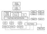
- FIG. 1shows a schematic block diagram illustrating an energy management system for practicing the method of the invention.
- FIG. 2shows two charts illustrating an example of circuit lists and HVAC lists.
- FIG. 3shows a graph of demand over fifteen minute intervals to illustrate methods for finding peaks for calculations.
- FIG. 4shows a graph of demand over fifteen minute intervals to illustrate prediction of load over a time interval.
- FIG. 5shows a graph of demand over fifteen minute intervals to illustrate sending intervals into curtailment.
- FIG. 1shows a schematic block diagram illustrating an exemplary embodiment of an energy management system for practicing the method of the invention.
- a site controller with embedded control algorithmscontrols multiple electrical loads on circuits 1 through N via light control panels (LCPs).
- the site controlleris typically wired to common voltages at an electrical distribution panel of a commercial or residential building facility via a main line meter (power monitor).
- the site controllerincludes memory and a CPU for respectively storing and implementing energy management algorithms in accordance with the invention, discussed below.
- the algorithmsaccept real-time power and environmental variable measurements (including readings from thermostats TStat 1 through TStat N) as inputs and determine how to control the power delivered on the circuits 1 through N and to control set points and other configurable settings such as enabling/disabling compressor stages on TStat 1 through TStat N.
- the site controllermay include a power supply and one or more wired or wireless local communication and control interfaces for controlling Circuit 1 through Circuit N and TStat 1 through TStat N.
- Thermostats TStat 1 through TStat Nprovide temperature and humidity inputs to the site controller, and output control signals to roof-top units RTU 1 through RTU N.
- a communication interfaceprovides bi-directional communication with a communication gateway, which in turn manages wired or wireless communications with a remote terminal.
- One or more power monitorsare coupled to the site controller either via wired or wireless connection.
- the power monitorincludes hardware and firmware to provide sampling functionality, including multiple analog-to-digital converters for multi-channel fast waveform sampling of inputs such as current and voltage.
- the power monitorincludes wired or wireless communication interfaces, current and voltage monitoring interfaces, memory, CPU, and may also include a power supply.
- the A/D converters and voltage and current monitoring interfaces of the power monitormay be integrated within the site controller to provide voltage and current monitoring without the use of an external power monitor. Further, additional environmental sensors, such as outdoor temperature sensors, may be monitored by the system. In yet another alternative embodiment, the control algorithms may be embedded and executed within the power monitor itself.
- the current and voltage monitoring interfacesconnect between the power circuits being monitored and the A/D converter. Each channel may be connected to a separate power circuit to monitor the flow of current through the circuit.
- the connectionis made with a current transformer at both a supply (i.e., hot) line and a return (i.e., neutral) line of the power circuit, which provides a waveform signal that is representative of the current flow at the connection point.
- FIG. 2shows two charts illustrating an example of circuit configuration lists and HVAC configuration lists. Loads can be disabled by the system in the order as listed therein, or as otherwise discussed in further detail below. Separate lists are stored for HVAC loads and non-HVAC loads.
- FIG. 3shows a graph illustrating demand over fifteen minute intervals.
- the graph lineis exaggerated for clarity to show some distinct peaks, and the actual load line would be much flatter.
- a dynamic load curtailment algorithmconstantly monitors the last seven days for the peak energy usage (in kw). If you imagine this graph in motion, it will constantly move to the left. At the point in time at which this chart was generated, the peak is at the end of day ⁇ 4. Each day, that peak will move to the left, to the end of day ⁇ 5, then ⁇ 6, then it will “fall off” the graph to the left. In the mean time, the “new peak” (at the end of day ⁇ 2) moves to the left also.
- the systemuses the “new peak.” Eventually, that new peak will fall off the graph to the left and be replaced with a new one, and so on.
- the number of days the algorithm uses to determine the peak energy usageis configurable and can be more or less than seven.
- the billing intervalsare configurable and can set to more or less than 15 minutes.
- FIG.shows what happens to the target load when the “old peak” falls off the left side of this chart and a “new peak” appears.
- the systemis looking at the last seven days for the peak, it is also predicting the load for the next billing interval, which is typically 15 minutes.
- the controllerhas enough information available to it to make the prediction accurately for the average load in the next 15 minutes.
- the loadis the average for the interval, not any one single point in the load.
- FIG. 5shows a graph of demand over fifteen minute intervals to illustrate sending intervals into curtailment.
- two intervalshave a predicted load over the target load. Those intervals begin curtailment depending on configuration of the system.
- the actions used to curtail loadare (a) de-energizing of circuits and (b) reduction of consumption of HVAC within comfort limits.
- To de-energize circuitsthe system turns off predefined circuits within predefined limits. These are “nice to have” circuits, like spotlights on the exterior of building or a wall heater.
- Reduce consumption of HVAC within comfort limitsby either turning off stage two (one of two compressors in the RTU) or tuning the set point to reduce cycles.
- total facility loadis monitored, for example via the main load power monitor, and predictions for total facility demand are calculated and compared to a target value for total facility KW demand.
- the demand intervalshould be configured as that of the customer's billing tariff. Projected load is determined based on real-time load information and other information such as typical equipment run-times and equipment operational schedules.
- set points or active stages for individual HVAC unitsare incrementally changed in an effort to reduce the associated load as needed to keep the total facility demand from exceeding the target limit. Control zones can also be de-activated in order to keep the target demand from being exceeded.
- HVAC unitscan be curtailed by either (a) turning off only stage 2 or (b) increasing or decreasing the cooling or heating set point, respectively, by several degrees (configurable).
- the curtailment option to be applied for a particular HVAC unitis configurable, along with the curtailment priority order. Curtailment priority order can be configured to rotate to ensure some runtime for each unit. In addition to the minimum on-time and off-time requirements enforced by the controlling thermostats, thermostat on and off time requirements are enforced by this control scheme as well.
- Control zonescan be curtailed by de-energizing their circuits for a configurable amount of time during the demand interval. This ensures that these loads will always run for a minimal amount of time. All control zones are the lowest priority in this control scheme and thus will be the first loads to be curtailed. Once all available control zones have been curtailed, only then would HVAC units be altered in accordance with configured run times. Only one load will be changed (control zone and/or HVAC units) per minute. Alternatively, other time intervals for changing loads could be configured.
- This control schemeis not synchronized with the demand interval.
- the sequence of operationis as follows:
- stage 2 of these unitsis re-enabled in a prioritized “staggered” fashion—if the thermostat off time has been satisfied.
- This control schemeis not synchronized with the demand interval.
- the sequence of operationis as follows:
- HVAC unitsWhen predicted total facility demand becomes less than the target total facility KW value, these HVAC units are returned to normal set point values in a prioritized “staggered” fashion—if the configured thermostat off time has been satisfied.
- these loadsare immediately disabled for the remainder of the interval if the predicted total facility demand exceeds the target facility KW value.
- the loadswill be disabled in the order as listed in the configuration.
- the total facility demand targetcan be determined by either (a) a predefined table of monthly target values (12 values—one for each calendar month), or (b) a dynamically calculated target value.
- controllersWith dynamic calculation of total facility target KW, controllers will automatically and dynamically calculate the target total facility KW value such that the target total facility KW is the greater of:
- Recent Occupied Average Total Facility Loadthe average value of total facility load during occupied hours for the previous seven (7) days (determined dynamically).
- Recent Total Facility Demand Peak or Recent Occupied Average Total Facility Loadcan be used alone to calculate the target total facility KW value.
- a configurable number of previous dayscan be used to derive these quantities.
- Target total facility KWis calculated at the beginning of each demand interval. The goal is to achieve a stable control scheme that automatically and gradually adjusts to the best achievable total facility demand deduction as total facility load characteristics vary over time.
- the 0.95 and 1.05 factors (above) on the dynamic calculationsare configurable and may need to be adjusted to achieve optimum stable demand reduction.
- Examples of computer-readable mediainclude but are not limited to recordable and non-recordable type media such as volatile and non-volatile memory devices, read only memory (ROM), random access memory (RAM), flash memory devices, floppy and other removable disks, magnetic disk storage media, optical storage media (e.g., Compact Disk Read-Only Memory (CD ROMS), Digital Versatile Disks (DVDs), etc.), among others.
- recordable and non-recordable type mediasuch as volatile and non-volatile memory devices, read only memory (ROM), random access memory (RAM), flash memory devices, floppy and other removable disks, magnetic disk storage media, optical storage media (e.g., Compact Disk Read-Only Memory (CD ROMS), Digital Versatile Disks (DVDs), etc.), among others.
- CD ROMSCompact Disk Read-Only Memory
- DVDsDigital Versatile Disks
- the load curtailment algorithms taught abovemay operate in combination with other energy management algorithms, including algorithms for HVAC recovery, HVAC setback, humidity control, and demand control ventilation. Such algorithms tune buildings to reduce power consumption while considering comfort.
- the algorithmsmay run on the site controller illustrated in FIG. 1 or in the power monitor, and discussed above.
- the algorithmsmay be configured to work together as follows.
- the load curtailment algorithm described aboveadjusts consumption down to contextual target that it calculates based on the historical consumption of the building.
- An HVAC Recovery algorithmefficiently returns buildings to occupied temperature settings, as disclosed in Provisional Patent Application No. 61/496,422, entitled “System and Method of Controlling Setback Recovery of a Power Consuming Device,” filed Jun. 13, 2011, and expressly incorporated herein in its entirety.
- An HVAC Setback algorithmefficiently returns buildings to unoccupied temperature settings, as disclosed in Provisional Patent Application No. 61/496,431, entitled “System and Method of Controlling the Setback of a Power Consuming Device, filed Jun. 13, 2011, and expressly incorporated herein in its entirety.
- a Humidity Control algorithmuses HVAC systems to remove humidity from indoor air.
- a Demand Control Ventilation (DCV) algorithmdraws external air into the system to affect air quality. Because the algorithms run on the same controller, the system can prevent conflicts between working algorithms by choosing the most energy efficient output of the algorithms. Each algorithm has its own comfort limits, so the most energy efficient output already considers comfort of a building's occupants.
Landscapes
- Engineering & Computer Science (AREA)
- General Engineering & Computer Science (AREA)
- Physics & Mathematics (AREA)
- Mechanical Engineering (AREA)
- Combustion & Propulsion (AREA)
- Chemical & Material Sciences (AREA)
- Signal Processing (AREA)
- Mathematical Physics (AREA)
- Fuzzy Systems (AREA)
- General Physics & Mathematics (AREA)
- Automation & Control Theory (AREA)
- Theoretical Computer Science (AREA)
- Power Engineering (AREA)
- Electromagnetism (AREA)
- Radar, Positioning & Navigation (AREA)
- Human Computer Interaction (AREA)
- Computational Linguistics (AREA)
- Evolutionary Computation (AREA)
- Data Mining & Analysis (AREA)
- Computing Systems (AREA)
- Artificial Intelligence (AREA)
- Software Systems (AREA)
- Supply And Distribution Of Alternating Current (AREA)
- Remote Monitoring And Control Of Power-Distribution Networks (AREA)
- Air Conditioning Control Device (AREA)
- Feedback Control In General (AREA)
Abstract
Description
- a) Predicted total facility demand exceeds the target total facility KW value;
- b) Zone temperature does not exceed the normal target zone temperature plus the predefined curtailment offset unless the system is in recovery in which case the zone temperature will not exceed unoccupied settings;
- c) Minimum configured thermostat on time has been satisfied.
- a) Predicted total facility demand exceeds the target total facility KW value;
- b) Minimum thermostat on time has been satisfied.
Claims (7)
Priority Applications (4)
| Application Number | Priority Date | Filing Date | Title |
|---|---|---|---|
| US13/425,195US8862280B1 (en) | 2011-06-13 | 2012-03-20 | Dynamic load curtailment system and method |
| US14/513,374US9880577B2 (en) | 2011-06-13 | 2014-10-14 | Dynamic load curtailment system and method |
| US15/842,227US10866609B2 (en) | 2011-06-13 | 2017-12-14 | Dynamic load curtailment system and method |
| US17/103,282US11747848B2 (en) | 2011-06-13 | 2020-11-24 | Dynamic load curtailment system and method |
Applications Claiming Priority (3)
| Application Number | Priority Date | Filing Date | Title |
|---|---|---|---|
| US201161496422P | 2011-06-13 | 2011-06-13 | |
| US201161496431P | 2011-06-13 | 2011-06-13 | |
| US13/425,195US8862280B1 (en) | 2011-06-13 | 2012-03-20 | Dynamic load curtailment system and method |
Related Child Applications (1)
| Application Number | Title | Priority Date | Filing Date |
|---|---|---|---|
| US14/513,374ContinuationUS9880577B2 (en) | 2011-06-13 | 2014-10-14 | Dynamic load curtailment system and method |
Publications (1)
| Publication Number | Publication Date |
|---|---|
| US8862280B1true US8862280B1 (en) | 2014-10-14 |
Family
ID=47357705
Family Applications (9)
| Application Number | Title | Priority Date | Filing Date |
|---|---|---|---|
| US13/425,195ActiveUS8862280B1 (en) | 2011-06-13 | 2012-03-20 | Dynamic load curtailment system and method |
| US13/495,720Active2035-05-10US9436199B2 (en) | 2011-06-13 | 2012-06-13 | Controlling the setback and setback recovery of a power-consuming device |
| US14/513,374ActiveUS9880577B2 (en) | 2011-06-13 | 2014-10-14 | Dynamic load curtailment system and method |
| US15/238,421AbandonedUS20160357209A1 (en) | 2011-06-13 | 2016-08-16 | Controlling the setback and setback recovery of a power-consuming device |
| US15/842,227ActiveUS10866609B2 (en) | 2011-06-13 | 2017-12-14 | Dynamic load curtailment system and method |
| US16/191,968AbandonedUS20190310673A1 (en) | 2011-06-13 | 2018-11-15 | Controlling the setback and setback recovery of a power-consuming device |
| US17/103,282ActiveUS11747848B2 (en) | 2011-06-13 | 2020-11-24 | Dynamic load curtailment system and method |
| US17/303,190AbandonedUS20220163989A1 (en) | 2011-06-13 | 2021-05-24 | Controlling the setback and setback recovery of a power-consuming device |
| US18/183,757ActiveUS12346142B2 (en) | 2011-06-13 | 2023-03-14 | Controlling the setback and setback recovery of a power-consuming device |
Family Applications After (8)
| Application Number | Title | Priority Date | Filing Date |
|---|---|---|---|
| US13/495,720Active2035-05-10US9436199B2 (en) | 2011-06-13 | 2012-06-13 | Controlling the setback and setback recovery of a power-consuming device |
| US14/513,374ActiveUS9880577B2 (en) | 2011-06-13 | 2014-10-14 | Dynamic load curtailment system and method |
| US15/238,421AbandonedUS20160357209A1 (en) | 2011-06-13 | 2016-08-16 | Controlling the setback and setback recovery of a power-consuming device |
| US15/842,227ActiveUS10866609B2 (en) | 2011-06-13 | 2017-12-14 | Dynamic load curtailment system and method |
| US16/191,968AbandonedUS20190310673A1 (en) | 2011-06-13 | 2018-11-15 | Controlling the setback and setback recovery of a power-consuming device |
| US17/103,282ActiveUS11747848B2 (en) | 2011-06-13 | 2020-11-24 | Dynamic load curtailment system and method |
| US17/303,190AbandonedUS20220163989A1 (en) | 2011-06-13 | 2021-05-24 | Controlling the setback and setback recovery of a power-consuming device |
| US18/183,757ActiveUS12346142B2 (en) | 2011-06-13 | 2023-03-14 | Controlling the setback and setback recovery of a power-consuming device |
Country Status (3)
| Country | Link |
|---|---|
| US (9) | US8862280B1 (en) |
| CA (1) | CA2839192C (en) |
| WO (1) | WO2012174130A2 (en) |
Cited By (9)
| Publication number | Priority date | Publication date | Assignee | Title |
|---|---|---|---|---|
| US20120323393A1 (en)* | 2011-06-17 | 2012-12-20 | Raphael Imhof | Automated demand response system |
| US9852481B1 (en)* | 2013-03-13 | 2017-12-26 | Johnson Controls Technology Company | Systems and methods for cascaded model predictive control |
| US10007259B2 (en) | 2013-03-13 | 2018-06-26 | Johnson Controls Technology Company | Systems and methods for energy cost optimization in a building system |
| US10088814B2 (en) | 2013-03-13 | 2018-10-02 | Johnson Controls Technology Company | System identification and model development |
| US10823443B2 (en) | 2017-07-20 | 2020-11-03 | Carrier Corporation | Self-adaptive smart setback control system |
| US20210010703A1 (en)* | 2013-03-15 | 2021-01-14 | Waterfurnace International, Inc. | Space conditioning control and monitoring method and system |
| US10976935B1 (en)* | 2020-02-11 | 2021-04-13 | EMC IP Holding Company LLC | Method and apparatus for assigning an allocated workload in a data center having multiple storage systems |
| US11135936B2 (en) | 2019-03-06 | 2021-10-05 | Fermata, LLC | Methods for using temperature data to protect electric vehicle battery health during use of bidirectional charger |
| US11958372B2 (en) | 2019-11-26 | 2024-04-16 | Fermata Energy Llc | Device for bi-directional power conversion and charging for use with electric vehicles |
Families Citing this family (45)
| Publication number | Priority date | Publication date | Assignee | Title |
|---|---|---|---|---|
| US8862280B1 (en)* | 2011-06-13 | 2014-10-14 | Gridpoint, Inc. | Dynamic load curtailment system and method |
| US9377212B2 (en)* | 2011-12-16 | 2016-06-28 | Lennox Industries Inc. | Time-based setback recovery |
| FR3004603B1 (en)* | 2013-04-10 | 2015-07-03 | Valeo Systemes De Controle Moteur | ROTARY DRIVE SYSTEM, INVERTER CONTROL METHOD, AND COMPUTER PROGRAM |
| JP6009098B2 (en)* | 2013-11-08 | 2016-10-19 | 三菱電機株式会社 | Air conditioner |
| US11100465B1 (en)* | 2014-02-12 | 2021-08-24 | Alarm.Com Incorporated | Rental property management technology |
| US9765984B2 (en) | 2014-04-02 | 2017-09-19 | Trane International Inc. | Thermostat temperature compensation modeling |
| CN105446242B (en)* | 2015-11-17 | 2018-11-16 | 高新兴科技集团股份有限公司 | A kind of smart machine automatic recognition system |
| US20180004171A1 (en) | 2016-06-30 | 2018-01-04 | Johnson Controls Technology Company | Hvac system using model predictive control with distributed low-level airside optimization and airside power consumption model |
| US11067955B2 (en)* | 2016-06-30 | 2021-07-20 | Johnson Controls Technology Company | HVAC system using model predictive control with distributed low-level airside optimization |
| US11789415B2 (en) | 2016-06-30 | 2023-10-17 | Johnson Controls Tyco IP Holdings LLP | Building HVAC system with multi-level model predictive control |
| US11138827B2 (en) | 2016-09-15 | 2021-10-05 | Simpsx Technologies Llc | Implementations of a computerized business transaction exchange for various users |
| US12001999B2 (en) | 2016-09-15 | 2024-06-04 | Circlesx Llc | Price based navigation |
| US12354033B2 (en) | 2016-09-15 | 2025-07-08 | Circlesx Llc | Time interval geolocation community objects with price-time priority queues for transformed time interval geolocation units |
| US11810023B2 (en) | 2018-10-22 | 2023-11-07 | Circlesx Llc | System and method for a transportation or freight capacity exchange for one or more transportation or freight capacity units |
| US12346987B2 (en) | 2016-09-15 | 2025-07-01 | Circlesx Llc | Price time priority queue routing for transportation capacity units |
| US11861527B2 (en) | 2018-11-07 | 2024-01-02 | Circlesx Llc | Financial swap payment structure method and system on transportation capacity unit assets |
| US12361486B2 (en) | 2016-09-15 | 2025-07-15 | Circlesx Llc | Toll and congestion community objects with price-time priority queues for transformed toll and congestion capacity units |
| US12152894B2 (en) | 2016-09-15 | 2024-11-26 | Circlesx Llc | Multi-dimension classification object matrices to estimate multi-dimensional representations with multi function device |
| US11035682B2 (en) | 2016-09-15 | 2021-06-15 | Simpsx Technologies Llc | Navigation routes as community object virtual hub sequences to which users may subscribe |
| US11880883B2 (en) | 2016-09-15 | 2024-01-23 | Circlesx Llc | Systems and methods for geolocation portfolio exchanges |
| US12320654B2 (en) | 2018-01-23 | 2025-06-03 | Circlesx Llc | Financial swap index method and system on transportation capacity units and trading derivative products based thereon |
| US11790382B2 (en) | 2016-09-15 | 2023-10-17 | Circlesx Llc | Method to transmit geolocation exchange based markets |
| US12141885B2 (en) | 2016-09-15 | 2024-11-12 | Circlesx Llc | Parking community objects with price-time priority queues for transformed parking units |
| US10460520B2 (en) | 2017-01-13 | 2019-10-29 | Simpsx Technologies Llc | Computer ball device for mixed reality, virtual reality, or augmented reality |
| US12039585B2 (en) | 2017-04-10 | 2024-07-16 | Circlesx Llc | System and method for blood and saliva optimized food consumption and delivery |
| US12165223B2 (en) | 2016-09-15 | 2024-12-10 | Circlesx Llc | Renewable energy community objects with price-time priority queues for transformed renewable energy units |
| US11157852B2 (en) | 2016-09-15 | 2021-10-26 | Simpsx Technologies Llc | Tool appliance community objects with price-time priority queues for transformed tool appliance units |
| US12260456B2 (en) | 2016-09-15 | 2025-03-25 | Circlesx Llc | Virtual reality, augmented reality, mixed reality data exchange social network with multi dimensional map tile porting |
| US12124976B2 (en) | 2018-01-23 | 2024-10-22 | Circlesx Llc | Market exchange for transportation capacity in transportation vehicles |
| US20190272589A1 (en) | 2016-09-15 | 2019-09-05 | Erik M. Simpson | Securitization of transportation units |
| US12106365B2 (en) | 2016-09-15 | 2024-10-01 | Circlesx Llc | Web browser and operating system portal and search portal with price time priority queues |
| US12154183B2 (en) | 2016-09-15 | 2024-11-26 | Circlesx Llc | System and method for a tutoring exchange for tutoring units |
| US11138661B2 (en) | 2016-09-15 | 2021-10-05 | Simpsx Technologies Llc | Agriculture community objects with price-time priority queues for transformed agriculture units |
| US11740777B2 (en) | 2016-09-15 | 2023-08-29 | Circlesx Llc | Multi-dimension information service helmet method and system |
| US11823090B2 (en) | 2016-09-15 | 2023-11-21 | Circlesx Llc | Transportation and freight and parking and tolling and curb capacity unit IPO method and system |
| US11215466B2 (en) | 2016-09-15 | 2022-01-04 | Circlesx Llc | Route community objects with price-time priority queues for transformed transportation units |
| US20190178518A1 (en) | 2017-12-07 | 2019-06-13 | Johnson Controls Technology Company | Thermostat with energy modeling |
| US10527307B2 (en)* | 2017-12-14 | 2020-01-07 | Khalifa University of Science and Technology | Methods and systems for controlling appliances |
| CN109990444B (en)* | 2017-12-29 | 2022-05-13 | 大金工业株式会社 | Air quality management system and method |
| CN110836514B (en)* | 2018-08-17 | 2021-01-29 | 珠海格力电器股份有限公司 | Control method and device of air conditioning unit |
| US11525593B2 (en) | 2019-03-27 | 2022-12-13 | Trane International Inc. | Prioritizing efficient operation over satisfying an operational demand |
| US12422158B2 (en) | 2021-08-30 | 2025-09-23 | Copeland Comfort Control Lp | Energy management and smart thermostat learning methods and control systems |
| US12386325B2 (en) | 2022-04-28 | 2025-08-12 | Inventus Holdings, Llc | Staggered cooling system controls for battery energy storage systems |
| US20250123016A1 (en)* | 2023-10-17 | 2025-04-17 | Carrier Corporation | Optimized setback control system and a method thereof |
| CN117474366B (en)* | 2023-12-27 | 2024-03-19 | 天津理工大学 | Intelligent energy consumption monitoring and management system and method |
Citations (2)
| Publication number | Priority date | Publication date | Assignee | Title |
|---|---|---|---|---|
| US5543667A (en) | 1992-12-29 | 1996-08-06 | Honeywell Inc. | Load control for partially increasing/decreasing power usage |
| US20080177423A1 (en)* | 2002-03-08 | 2008-07-24 | Brickfield Peter J | Automatic energy management and energy consumption reduction, especially in commercial and multi-building systems |
Family Cites Families (53)
| Publication number | Priority date | Publication date | Assignee | Title |
|---|---|---|---|---|
| US4272012A (en) | 1979-03-09 | 1981-06-09 | Molnar John R | Method and system for controlling a plurality of temperature conditioning units |
| US4386649A (en) | 1980-07-15 | 1983-06-07 | Nuclear Systems, Inc. | Programmable thermostatic control device |
| US4522336A (en) | 1982-12-09 | 1985-06-11 | Honeywell Inc. | Adaptive optimum start/stop control system |
| US4620668A (en)* | 1985-04-25 | 1986-11-04 | Honeywell Inc. | Adaptive control system |
| US4991770A (en) | 1990-03-27 | 1991-02-12 | Honeywell Inc. | Thermostat with means for disabling PID control |
| US5025984A (en) | 1990-06-22 | 1991-06-25 | Honeywell Inc. | Setback thermostat with recovery start time selected non-linearly |
| US5197666A (en)* | 1991-03-18 | 1993-03-30 | Wedekind Gilbert L | Method and apparatus for estimation of thermal parameter for climate control |
| US5115967A (en)* | 1991-03-18 | 1992-05-26 | Wedekind Gilbert L | Method and apparatus for adaptively optimizing climate control energy consumption in a building |
| US5270952A (en) | 1991-09-30 | 1993-12-14 | Honeywell Inc. | Self-adjusting recovery algorithm for a microprocessor-controlled setback thermostat |
| US5244146A (en)* | 1992-05-08 | 1993-09-14 | Homebrain, Inc. | Energy-conserving thermostat and method |
| US5219119A (en) | 1992-09-21 | 1993-06-15 | Honeywell Inc. | Thermostat-type setback controller having a recovery set point which depends on the time-based value of a sensor signal |
| US5314004A (en) | 1993-05-28 | 1994-05-24 | Honeywell Inc. | Thermostat for a variable capacity HVAC and method for providing a ramping set point on a setback thermostat |
| US6116512A (en) | 1997-02-19 | 2000-09-12 | Dushane; Steven D. | Wireless programmable digital thermostat system |
| US5395042A (en)* | 1994-02-17 | 1995-03-07 | Smart Systems International | Apparatus and method for automatic climate control |
| US5555927A (en) | 1995-06-07 | 1996-09-17 | Honeywell Inc. | Thermostat system having an optimized temperature recovery ramp rate |
| US5822997A (en) | 1995-12-08 | 1998-10-20 | Gas Research Institute | Thermostat setback recovery method and apparatus |
| US6290140B1 (en)* | 1999-03-04 | 2001-09-18 | Energyiq Systems, Inc. | Energy management system and method |
| US6700224B2 (en)* | 2000-08-04 | 2004-03-02 | Energy Technologies, L.L.C. | Security and energy control system |
| US6478233B1 (en) | 2000-12-29 | 2002-11-12 | Honeywell International Inc. | Thermal comfort controller having an integral energy savings estimator |
| US6402043B1 (en) | 2001-10-18 | 2002-06-11 | John F. Cockerill | Method for controlling HVAC units |
| US6634566B2 (en) | 2002-02-12 | 2003-10-21 | Carrier Corporation | Advanced setback reporting thermostat |
| US7147168B1 (en)* | 2003-08-11 | 2006-12-12 | Halton Company | Zone control of space conditioning system with varied uses |
| EP1429082B1 (en) | 2002-12-10 | 2012-04-11 | LG Electronics Inc. | Central control system and method for controlling air conditioners |
| US7222494B2 (en) | 2004-01-07 | 2007-05-29 | Honeywell International Inc. | Adaptive intelligent circulation control methods and systems |
| US7099748B2 (en)* | 2004-06-29 | 2006-08-29 | York International Corp. | HVAC start-up control system and method |
| US7809472B1 (en) | 2004-07-06 | 2010-10-05 | Custom Manufacturing & Engineering, Inc. | Control system for multiple heating, ventilation and air conditioning units |
| US8527109B2 (en)* | 2006-07-11 | 2013-09-03 | Regen Energy Inc. | Method and apparatus for managing an energy consuming load |
| US20080083834A1 (en)* | 2006-10-04 | 2008-04-10 | Steve Krebs | System and method for selecting an operating level of a heating, ventilation, and air conditioning system |
| US20080099570A1 (en)* | 2006-10-04 | 2008-05-01 | Steve Krebs | System and method for estimating temperature drift and drive curves |
| US7966104B2 (en) | 2007-03-26 | 2011-06-21 | Siemens Corporation | Apparatus and method for the control of the indoor thermal environment having feed forward and feedback control using adaptive reference models |
| US8010237B2 (en)* | 2008-07-07 | 2011-08-30 | Ecofactor, Inc. | System and method for using ramped setpoint temperature variation with networked thermostats to improve efficiency |
| US8550370B2 (en)* | 2008-12-30 | 2013-10-08 | Zoner Llc | Automatically balancing register for HVAC systems |
| US8141791B2 (en)* | 2009-03-26 | 2012-03-27 | Howard Rosen | Energy management improvement for a heating system with reduced setpoint temperature during no occupancy based upon historical sampling of room thermal response with highest power heat applied |
| US20100298984A1 (en)* | 2009-05-21 | 2010-11-25 | Lennox Industries, Incorporated | Usb hvac service verification |
| US8204628B2 (en) | 2010-03-24 | 2012-06-19 | Honeywell International Inc. | Setpoint recovery with utility time of day pricing |
| US10281938B2 (en)* | 2010-04-14 | 2019-05-07 | Robert J. Mowris | Method for a variable differential variable delay thermostat |
| US9310792B2 (en) | 2010-05-03 | 2016-04-12 | Battelle Memorial Institute | Scheduling and modeling the operation of controllable and non-controllable electronic devices |
| US8556188B2 (en) | 2010-05-26 | 2013-10-15 | Ecofactor, Inc. | System and method for using a mobile electronic device to optimize an energy management system |
| US8606374B2 (en) | 2010-09-14 | 2013-12-10 | Nest Labs, Inc. | Thermodynamic modeling for enclosures |
| US20120085831A1 (en) | 2010-10-07 | 2012-04-12 | Energy Eye, Inc. | Systems and methods for controlling the temperature of a room based on occupancy |
| US8560127B2 (en)* | 2011-01-13 | 2013-10-15 | Honeywell International Inc. | HVAC control with comfort/economy management |
| US8862280B1 (en) | 2011-06-13 | 2014-10-14 | Gridpoint, Inc. | Dynamic load curtailment system and method |
| CA3044757C (en)* | 2011-10-21 | 2021-11-09 | Google Llc | User-friendly, network connected learning thermostat and related systems and methods |
| US9377212B2 (en)* | 2011-12-16 | 2016-06-28 | Lennox Industries Inc. | Time-based setback recovery |
| KR20150020171A (en)* | 2012-05-17 | 2015-02-25 | 찬, 훈 맨 레나 | Information control system |
| US10788227B2 (en)* | 2013-03-15 | 2020-09-29 | Waterfurnace International Inc. | Space conditioning control and monitoring method and system |
| US9910449B2 (en)* | 2013-04-19 | 2018-03-06 | Google Llc | Generating and implementing thermodynamic models of a structure |
| US20150163945A1 (en)* | 2013-12-11 | 2015-06-11 | Honeywell International Inc. | Hvac controller with thermistor biased against an outer housing |
| US10012406B2 (en)* | 2014-05-15 | 2018-07-03 | Samsung Electronics Co., Ltd. | Method and apparatus for controlling temperature |
| US20160201933A1 (en)* | 2015-01-14 | 2016-07-14 | Google Inc. | Predictively controlling an environmental control system |
| US9869484B2 (en)* | 2015-01-14 | 2018-01-16 | Google Inc. | Predictively controlling an environmental control system |
| US10254726B2 (en)* | 2015-01-30 | 2019-04-09 | Schneider Electric USA, Inc. | Interior comfort HVAC user-feedback control system and apparatus |
| US10823443B2 (en)* | 2017-07-20 | 2020-11-03 | Carrier Corporation | Self-adaptive smart setback control system |
- 2012
- 2012-03-20USUS13/425,195patent/US8862280B1/enactiveActive
- 2012-06-13USUS13/495,720patent/US9436199B2/enactiveActive
- 2012-06-13CACA2839192Apatent/CA2839192C/enactiveActive
- 2012-06-13WOPCT/US2012/042276patent/WO2012174130A2/enactiveApplication Filing
- 2014
- 2014-10-14USUS14/513,374patent/US9880577B2/enactiveActive
- 2016
- 2016-08-16USUS15/238,421patent/US20160357209A1/ennot_activeAbandoned
- 2017
- 2017-12-14USUS15/842,227patent/US10866609B2/enactiveActive
- 2018
- 2018-11-15USUS16/191,968patent/US20190310673A1/ennot_activeAbandoned
- 2020
- 2020-11-24USUS17/103,282patent/US11747848B2/enactiveActive
- 2021
- 2021-05-24USUS17/303,190patent/US20220163989A1/ennot_activeAbandoned
- 2023
- 2023-03-14USUS18/183,757patent/US12346142B2/enactiveActive
Patent Citations (2)
| Publication number | Priority date | Publication date | Assignee | Title |
|---|---|---|---|---|
| US5543667A (en) | 1992-12-29 | 1996-08-06 | Honeywell Inc. | Load control for partially increasing/decreasing power usage |
| US20080177423A1 (en)* | 2002-03-08 | 2008-07-24 | Brickfield Peter J | Automatic energy management and energy consumption reduction, especially in commercial and multi-building systems |
Cited By (18)
| Publication number | Priority date | Publication date | Assignee | Title |
|---|---|---|---|---|
| US10110002B2 (en) | 2011-06-17 | 2018-10-23 | Siemens Industry, Inc. | Automated demand response system |
| US9310786B2 (en)* | 2011-06-17 | 2016-04-12 | Siemens Industry, Inc. | Automated demand response scheduling to reduce electrical loads |
| US20120323393A1 (en)* | 2011-06-17 | 2012-12-20 | Raphael Imhof | Automated demand response system |
| US10580097B2 (en)* | 2013-03-13 | 2020-03-03 | Johnson Controls Technology Company | Systems and methods for cascaded model predictive control |
| US10088814B2 (en) | 2013-03-13 | 2018-10-02 | Johnson Controls Technology Company | System identification and model development |
| US10007259B2 (en) | 2013-03-13 | 2018-06-26 | Johnson Controls Technology Company | Systems and methods for energy cost optimization in a building system |
| US20200143491A1 (en)* | 2013-03-13 | 2020-05-07 | Johnson Controls Technology Company | Systems and methods for cascaded model predictive control |
| US9852481B1 (en)* | 2013-03-13 | 2017-12-26 | Johnson Controls Technology Company | Systems and methods for cascaded model predictive control |
| US12354174B2 (en)* | 2013-03-13 | 2025-07-08 | Johnson Controls Technology Company | Systems and methods for cascaded model predictive control |
| US11086276B2 (en) | 2013-03-13 | 2021-08-10 | Johnson Controls Tyco IP Holdings LLP | System identification and model development |
| US11592201B2 (en)* | 2013-03-15 | 2023-02-28 | Waterfurnace International Inc. | Space conditioning control and monitoring method and system |
| US20210010703A1 (en)* | 2013-03-15 | 2021-01-14 | Waterfurnace International, Inc. | Space conditioning control and monitoring method and system |
| US12305868B2 (en) | 2013-03-15 | 2025-05-20 | Waterfurnace International, Inc. | Space conditioning control and monitoring method and system |
| US10823443B2 (en) | 2017-07-20 | 2020-11-03 | Carrier Corporation | Self-adaptive smart setback control system |
| US11958376B2 (en) | 2019-03-06 | 2024-04-16 | Fermata Energy Llc | Methods for using cycle life data to protect electric vehicle battery health during use of bidirectional charger |
| US11135936B2 (en) | 2019-03-06 | 2021-10-05 | Fermata, LLC | Methods for using temperature data to protect electric vehicle battery health during use of bidirectional charger |
| US11958372B2 (en) | 2019-11-26 | 2024-04-16 | Fermata Energy Llc | Device for bi-directional power conversion and charging for use with electric vehicles |
| US10976935B1 (en)* | 2020-02-11 | 2021-04-13 | EMC IP Holding Company LLC | Method and apparatus for assigning an allocated workload in a data center having multiple storage systems |
Also Published As
| Publication number | Publication date |
|---|---|
| US12346142B2 (en) | 2025-07-01 |
| US20210318707A1 (en) | 2021-10-14 |
| US20220163989A1 (en) | 2022-05-26 |
| US20180113484A1 (en) | 2018-04-26 |
| US9436199B2 (en) | 2016-09-06 |
| US20130013122A1 (en) | 2013-01-10 |
| US20190310673A1 (en) | 2019-10-10 |
| WO2012174130A3 (en) | 2013-02-21 |
| CA2839192A1 (en) | 2012-12-20 |
| US9880577B2 (en) | 2018-01-30 |
| US20240045459A1 (en) | 2024-02-08 |
| US20160357209A1 (en) | 2016-12-08 |
| CA2839192C (en) | 2024-01-23 |
| US10866609B2 (en) | 2020-12-15 |
| US11747848B2 (en) | 2023-09-05 |
| WO2012174130A2 (en) | 2012-12-20 |
| US20150142194A1 (en) | 2015-05-21 |
Similar Documents
| Publication | Publication Date | Title |
|---|---|---|
| US11747848B2 (en) | Dynamic load curtailment system and method | |
| Korkas et al. | Grid-connected microgrids: Demand management via distributed control and human-in-the-loop optimization | |
| KR100844324B1 (en) | Demand control system and demand control method of multi air conditioner | |
| US20200393157A1 (en) | Building hvac system with predictive temperature and humidity control | |
| US7992630B2 (en) | System and method for pre-cooling of buildings | |
| EP2874263B1 (en) | Server device and electrical power control system | |
| US10116136B2 (en) | Primary frequency control through simulated droop control with electric loads | |
| US10544956B2 (en) | HVAC system start/stop control | |
| KR101936633B1 (en) | Air conditioner and controlling method for the same | |
| CN105190193B (en) | Air conditioning control device, air-conditioner control system and air conditioning control method | |
| EP3650761B1 (en) | Control of heating, ventilation, air-conditioning | |
| KR20150040133A (en) | Apparatus and method for controlling an air conditioner, air conditioning system | |
| WO2014115247A1 (en) | System controller, facility management system, demand control method, and program | |
| KR20160009117A (en) | System for auto building control | |
| JPWO2014199427A1 (en) | Control device for air conditioner and control method for air conditioner | |
| EP3080520B1 (en) | Method and system for limiting power consumption | |
| KR20160009116A (en) | Method for managing building energy based on submetering | |
| WO2014010076A1 (en) | Device for controlling facility equipment | |
| JP2017010815A (en) | Rating current selection system of circuit breaker, rating current selection method for circuit breaker and program | |
| EP3080521A1 (en) | Method and system for controlling consumption |
Legal Events
| Date | Code | Title | Description |
|---|---|---|---|
| AS | Assignment | Owner name:GRIDPOINT, INC., VIRGINIA Free format text:ASSIGNMENT OF ASSIGNORS INTEREST;ASSIGNORS:DYESS, DANNY K.;TAMAGNI, ARMAND J., JR;VINSON, MARK W.;SIGNING DATES FROM 20120518 TO 20120525;REEL/FRAME:028307/0174 | |
| AS | Assignment | Owner name:MCHENRY LLC, NEW YORK Free format text:SECURITY AGREEMENT;ASSIGNOR:GRIDPOINT, INC.;REEL/FRAME:032133/0617 Effective date:20140128 | |
| STCF | Information on status: patent grant | Free format text:PATENTED CASE | |
| FEPP | Fee payment procedure | Free format text:MAINTENANCE FEE REMINDER MAILED (ORIGINAL EVENT CODE: REM.) | |
| FEPP | Fee payment procedure | Free format text:SURCHARGE FOR LATE PAYMENT, SMALL ENTITY (ORIGINAL EVENT CODE: M2554); ENTITY STATUS OF PATENT OWNER: SMALL ENTITY | |
| MAFP | Maintenance fee payment | Free format text:PAYMENT OF MAINTENANCE FEE, 4TH YR, SMALL ENTITY (ORIGINAL EVENT CODE: M2551); ENTITY STATUS OF PATENT OWNER: SMALL ENTITY Year of fee payment:4 | |
| AS | Assignment | Owner name:GRIDPOINT, INC, VIRGINIA Free format text:SECURITY INTEREST;ASSIGNOR:MCHENRY LLC;REEL/FRAME:048834/0274 Effective date:20190402 | |
| AS | Assignment | Owner name:GRIDPOINT, INC, VIRGINIA Free format text:CORRECTIVE ASSIGNMENT TO CORRECT THE NATURE OF CONVEYANCE PREVIOUSLY RECORDED AT REEL: 048834 FRAME: 0274. ASSIGNOR(S) HEREBY CONFIRMS THE ASSIGNMENT;ASSIGNOR:MCHENRY LLC;REEL/FRAME:049009/0882 Effective date:20190402 Owner name:GRIDPOINT, INC, VIRGINIA Free format text:CORRECTIVE ASSIGNMENT TO CORRECT THE NATURE OF CONVEYANCE PREVIOUSLY RECORDED AT REEL: 048834 FRAME: 0274. ASSIGNOR(S) HEREBY CONFIRMS THE RELEASE OF SECURITY INTEREST;ASSIGNOR:MCHENRY LLC;REEL/FRAME:049009/0882 Effective date:20190402 | |
| MAFP | Maintenance fee payment | Free format text:PAYMENT OF MAINTENANCE FEE, 8TH YR, SMALL ENTITY (ORIGINAL EVENT CODE: M2552); ENTITY STATUS OF PATENT OWNER: SMALL ENTITY Year of fee payment:8 |