US8861635B2 - Setting radio frequency (RF) beamformer antenna weights per data-stream in a multiple-input-multiple-output (MIMO) system - Google Patents
Setting radio frequency (RF) beamformer antenna weights per data-stream in a multiple-input-multiple-output (MIMO) systemDownload PDFInfo
- Publication number
- US8861635B2 US8861635B2US14/065,182US201314065182AUS8861635B2US 8861635 B2US8861635 B2US 8861635B2US 201314065182 AUS201314065182 AUS 201314065182AUS 8861635 B2US8861635 B2US 8861635B2
- Authority
- US
- United States
- Prior art keywords
- beamformer
- antennas
- beamformers
- phase
- denotes
- Prior art date
- Legal status (The legal status is an assumption and is not a legal conclusion. Google has not performed a legal analysis and makes no representation as to the accuracy of the status listed.)
- Expired - Fee Related
Links
Images


Classifications
- H—ELECTRICITY
- H04—ELECTRIC COMMUNICATION TECHNIQUE
- H04B—TRANSMISSION
- H04B7/00—Radio transmission systems, i.e. using radiation field
- H04B7/02—Diversity systems; Multi-antenna system, i.e. transmission or reception using multiple antennas
- H04B7/04—Diversity systems; Multi-antenna system, i.e. transmission or reception using multiple antennas using two or more spaced independent antennas
- H04B7/08—Diversity systems; Multi-antenna system, i.e. transmission or reception using multiple antennas using two or more spaced independent antennas at the receiving station
- H04B7/0837—Diversity systems; Multi-antenna system, i.e. transmission or reception using multiple antennas using two or more spaced independent antennas at the receiving station using pre-detection combining
- H04B7/0842—Weighted combining
- H04B7/086—Weighted combining using weights depending on external parameters, e.g. direction of arrival [DOA], predetermined weights or beamforming
- H—ELECTRICITY
- H04—ELECTRIC COMMUNICATION TECHNIQUE
- H04B—TRANSMISSION
- H04B7/00—Radio transmission systems, i.e. using radiation field
- H04B7/02—Diversity systems; Multi-antenna system, i.e. transmission or reception using multiple antennas
- H04B7/04—Diversity systems; Multi-antenna system, i.e. transmission or reception using multiple antennas using two or more spaced independent antennas
- H04B7/08—Diversity systems; Multi-antenna system, i.e. transmission or reception using multiple antennas using two or more spaced independent antennas at the receiving station
- H04B7/0868—Hybrid systems, i.e. switching and combining
- H04B7/0874—Hybrid systems, i.e. switching and combining using subgroups of receive antennas
- H—ELECTRICITY
- H04—ELECTRIC COMMUNICATION TECHNIQUE
- H04B—TRANSMISSION
- H04B7/00—Radio transmission systems, i.e. using radiation field
- H04B7/02—Diversity systems; Multi-antenna system, i.e. transmission or reception using multiple antennas
- H04B7/04—Diversity systems; Multi-antenna system, i.e. transmission or reception using multiple antennas using two or more spaced independent antennas
- H04B7/0413—MIMO systems
- H04B7/0417—Feedback systems
Definitions
- the present inventionrelates generally to the field of radio frequency (RF) multiple-input-multiple-output (MIMO) systems and more particularly to systems and methods for RF MIMO systems using RF beamforming and/or digital signal processing, to augment the receiver performance.
- RFradio frequency
- MIMOmultiple-input-multiple-output
- MIMOis defined as the use of multiple antennas at both the transmitter and receiver to improve communication performance (measured by predefined metrics known in the art). MIMO offers significant increases in data throughput and link range without additional bandwidth or increased transmit power. It achieves this goal by spreading the transmit power over the antennas to achieve spatial multiplexing that improves the spectral efficiency (more bits per second per Hz of bandwidth) or to achieve a diversity gain that improves the link reliability (reduced fading), or increased antenna directivity.
- MIMO receiving schemesare known to be used such as channel estimation and blind scan.
- beamformingsometimes referred to as “spatial filtering” as used herein, is a signal processing technique used in antenna arrays for directional signal transmission or reception. This is achieved by combining elements in the array in such a way that signals at particular angles experience constructive interference while others experience destructive interference. Beamforming can be used at both the transmitting and receiving ends in order to achieve spatial selectivity.
- beamformerrefers to RF circuitry that implements beamforming and usually includes a combiner and may further include switches, controllable phase shifters, and in some cases amplifiers and/or attenuators. For the sake of simplicity, in the following text, any referral to “phase” may also include a “gain” or “attenuation” of the signal.
- look through methodrefers to receivers that use a single receive antenna in each beamformer at a time in order to carry out channel estimation and obtain the channel information (components of H being the channel matrix).
- Rx RDNReceived Radio Distribution Network
- hybrid MIMO RDNis defined as a MIMO system that employs two or more antennas per channel (N is the number of channels and M is the total number of antennae and M>N). This architecture employs a beamformer for each channel so that two or more antennas are combined for each radio circuit that is connected to each one of the channels.
- the individual signalswhen the phases of the received signals from each antenna are properly adjusted or tuned with respect to one another, the individual signals may be combined and result in an improved performance of the receiving system.
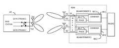
- FIG. 1shows a non-limiting example of a standard 2 ⁇ 2 MIMO radio 20 with two antennas A and B communicating with a base station 10 having two transmit antennas radiating Tx1 and Tx2 according to the prior art.
- each transmit antennawill transmit portion of the two data streams with pre-coding weight W.
- the basebandprocesses channel estimation separates them using the knowledge of pre-coding weight. It is noted that the receiver always knows the transmit pre-coding weight W, either by its own feedback to transmitter or by being informed by the transmitter in advance.
- the pre-coding weight Wis configured to de-correlate the data streams by forming two orthogonal beams: one for each data stream, at the receiver.
- the challenge of selecting the phases in the receive antennas coupled to the beamformers in the hybrid MIMO RDN architectureare addressed in order to maximize the signal for each data stream directly by an individual beamformer or to maximize the signal for all data streams collectively, in an architecture in which the number of receive antennas (M) is greater than the number of transmit antennas (N).
- the channel estimation information of individual Rx antennae.g., via look through
- the knowledge of pre-coding weight Wmay be used in order to tune the receive antennas such that each beamformer maximizes the received power of one particular data stream in the full rank MIMO operation.
- the phase settings Q for all receive antennasmay be obtained for each beamformer-data stream mapping configurations.
- a method to select the optimal beamformer-data stream mapping configurationis provided herein.
- An embodiment of the methodis based on seeking the maximum total received power for all data streams (i.e., the maximum sum of squared singular values of the transmission matrix: Q*H*W).
- a method to select the optimal beamformer-data stream mapping configurationis provided herein.
- An embodiment of the methodis based on seeking the most uniformly distributed gains for all data streams (i.e., minimal cond(Q*H*W) which is the ratio of the maximum singular value to the minimum singular value of the transmission matrix.
- Another embodimentis based on seeking the overall MIMO capacity optimization by selecting the beamformer-data stream mapping configuration that has cond(Q*H*W) below a certain threshold (e.g., 2) and the maximum received power among the mapping configurations.
- a certain thresholde.g., 2
- the MIMO Rx RDN systemmay have switch matrix to pool the receive antennas among beamformers.
- the optimization computation in the aforementioned methodsmay be applied to the pooled antenna configurations to generalize the optimization process and may get the better optimization results.
- FIG. 1is a high level block diagram illustrating a system according to some embodiments of the prior art
- FIG. 2is a high level block diagram illustrating an exemplary 2 ⁇ 2 MIMO system augmented with an Rx RDN according to one embodiment of the invention
- FIG. 3is a high level block diagram illustrating an exemplary 2 ⁇ 2 MIMO system augmented with an Rx RDN and with a switch matrix for antenna pooling according to another embodiment of the invention
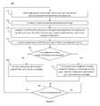
- FIG. 4is a flowchart describing an example procedure to set the phases for rx antennae in beamformer such that one beamformer maximizes the power for one data stream and then select the beamformer-data stream mapping configuration that maximizes the total power of all data streams according to an embodiment of the invention
- FIG. 5is a flowchart describing another embodiment of a method for setting set the phases of the receive antennas for each beamformer-data stream mapping configuration and then select the configuration that maximizes the total capacity of the MIMO system augmented with an Rx RDN according to an embodiment of the invention.
- FIG. 2shows an example of a 2 ⁇ 2 MIMO RDN architecture in which each receive antenna as shown in FIG. 1 such as A 1 , and B 1 are enhanced by adding another antenna, A 2 and B 2 respectively, thus providing reception by four antennas instead of two.
- the hybrid MIMO RDN architecturemay further include beamformer 1 30 - 1 and beamformer 2 30 - 2 each including phase shifters 40 - 1 and 40 - 2 and combiners 50 - 1 and 50 - 2 respectively.
- FIG. 3shows an exemplary 2 ⁇ 2 MIMO with Rx RDN system capable of antenna pooling.
- Embodiments of the present inventioninclude a system for setting weights per data-stream in a multiple-input-multiple-output (MIMO).
- the systemmay include: a number of receive antennas A 1 , A 2 , B 1 , B 2 configured to receive transmitted signals associated with respective data streams transmitted from a base station 10 ; a number of beamformers 30 - 1 and 30 - 2 connected to the receive antennas A 1 , A 2 , B 1 , and B 2 , configured to combine signals using combiners 50 - 1 and 50 - 2 received by the antennas.
- the systemmay further include a baseband module coupled to the beamformers via the radio and configured to apply at least one MIMO receiving scheme to the combined signals.
- the systemmay further include a control module possibly but not necessarily inside the baseband module configured, inter alia, to: (1) assign each of the receive antennas in each beamformer with a phase that optimizes reception e.g., in interference plus noise (SINR) sense, of at least one of the data streams; (2) compare overall performance of the mapping configurations which map between the beamformers and the data streams (e.g., compare the performance of each configuration to each other); and (3) select the mapping configuration which results in higher SINR measured at the baseband module. For example, the beam created by A 1 A 2 tuned to maximize data stream 1 , beam created by B 1 B 2 is tuned to maximize data stream 2 , and vice versa.
- SINRinterference plus noise
- the systemmay provide antenna pooling capability.
- switch matrix 60may be configured to pool the antenna A 2 and B 1 between the two beamformers in order to achieve better performance by selecting a better configuration from antenna phase perspective.
- the Rx RDNcan generate the multiple receive beams to further enhance the data streams signal by tuning each receive beam to an individual data stream (beam), respectively.
- the Rx RDNmay then minimize the cross talk and maximize the signal-to-noise ratio for the MIMO system.
- Combiners 50 - 1 and 50 - 2are to be tuned individually for the two separate data streams.
- the phases for receive antennaeare selected and set such that each beamformer maximizes the received power for one particular data stream (e.g., beamformer 1 , 2 . . . and N to maximize the received power for data stream 1 , 2 , . . . and N, respectively), and select other phases to configure different beamformer-data stream mapping (e.g., beamformer 1 , 2 , . . . and N maps to data stream N, 1 , 2 , . . . and N ⁇ 1, respectively) by using the known pre-coding weight, and channel estimation from “look through”.
- beamformer 1 , 2 , . . . and Nmaps to data stream N, 1 , 2 , . . . and N ⁇ 1, respectively
- the mapping configuration that maximizes the total received power of all data streams, or maximizes the SINRmay be selected or chosen from the mapping configurations. Phases are then set according to the selected configuration;
- the condition of the transmission matrix for all beamformer-data stream mapping configurationsi.e., cond(transmission matrix)
- This conditionis defined as the ratio of the maximum singular value to the minimum singular value of the transmission matrix, which represents the uniformity of the channel gains). If all the configurations experience relatively non-uniform channel gains, then the configuration that have the most uniform channel gains (i.e., minimum cond(transmission matrix)) is selected. On the other hand, a pool of configurations that have cond(transmission matrix) all below a pre-set threshold (e.g., 2), may be found. The configuration from the pool that maximizes the total received power of all data streams may be selected from the pool and the phases are set accordingly to optimize the overall performance (e.g., total capacity) for the MIMO system augmented with an Rx RDN.
- the receive antennasmay be pooled among beamformers and thus extend the choice of beamformer-data stream mapping configurations for the optimization computation to enhance the aforementioned three embodiments.
- Qis a 2 by (2*k) matrix presenting the phase settings of the Rx antennas in the RDN
- His a (2*k) by 2 matrix
- Wis a 2 by 2 matrix presenting the pre-coding weights to map the data streams to the transmit antennas and de-correlate the two data streams.
- the pre-coding weight Wis known to the receiver either by its feedback (e.g., PMI—Precoding Matrix Indicator) to the transmitter or informed by the transmitter in advanced.
- FIGS. 4 and 5show two exemplary procedures for obtaining the phase settings for all Rx antennae so that each beamformer maximizes the received power for a specific data stream and then select the optimal beamformer-data stream mapping configuration and then set the antennas accordingly.
- User equipment(“UE” or “a UE”) may be a device such as a cellular telephone, wireless-capable computer or laptop computer, smartphone, or other wireless or cellular capable device.
- a timermay be set, based on the mobility detection being parameters that determine how the channel changes over time, a time for repeating the optimization process.
- the receiversusing the look through method (e.g., one Rx antenna in each beamformer) to carry out channel estimation and obtain the channel information (components of H), shown on the steps of 410 and 420 , also on step 510 and 520 .
- the look through methode.g., one Rx antenna in each beamformer
- Step 430shows the computation of H*W and how to obtain the phase setting Q for the receive antennae such that each beamformer maximizes the received power for a specific data stream; and obtain all the phase settings Q's for the different configurations of beamformer-data stream mapping.
- the aforementioned computationmay include the configurations of antenna pooling.
- Antennas poolingextends the choices for the match of beamformer to data stream and may result in a better optimization results.
- His a 2 by 2 matrix, representing the channels between the 2 transmit antennas and 2 receive antennas.
- Y[y 1 , y 2 ]
- X[x 1 , x 2 ] [ y 1 , y 2 ]
- TH*W*[x 1 , x 2 ]
- y 1( h 11 w 11 +h 12 w 21 ) x 1 +( h 11 w 12 +h 12 w 22 )
- x 2a 11 x 1 +a 12 x 2
- y 2( h 21 w 11 +h 22 w 21 ) x 1 +( h 21 w 12 +h 22 w 22 )
- x 2a 21 x 1 +a 22 x 2
- a 11 for beamformer 1may be coherently combined to maximize the received power of data stream 1 , and coherently combine a 22 for beamformer 2 to maximize the received power of data stream 2 .
- a 12 (a 21 ) for beamformer 1 ( 2 )may be coherently combine to maximize the received power of data stream 2 (1).
- the phases for the two antennaemay be set such that the two a ij are coherently combined. It is noted that all the receivers/beamformers should have a common reference phase (e.g., 360 degrees).
- the phase setting for receive antennasmay be generalized such that each beamformer maximizes the received power of a specific data stream in the MIMO system augmented with Rx RDN.
- phase setting Q for each beamformer-data stream mapping configurationcan then be created accordingly.
- step 440shows the step to compute the singular values of the transmission matrix Q*H*W for all Q′s (beamformer-data stream mappings).
- the beamformer-data stream mapping configurationmay be selected with maximum ⁇ i 2 and set the phases (Q) accordingly to optimize the MIMO system augmented with an Rx RDN.
- pre-set timeris checked in step 460 for re-tuning the Rx RDN.
- the timermay be set based on UE mobility.
- flowchart 500describes another method to select the beamformer-data stream mapping configuration and set phase according to the select configuration for optimizing the hybrid MIMO system.
- Step 540shows the step to compute the singular values of the transmission matrix Q*H*W and cond(Q*H*W) for all Q's (beamformer-data stream mappings).
- cond(Q*H*W)is defined as the ratio of the maximal singular value to the minimal singular value of matrix Q*H*W. The smaller value of cond(Q*H*W) results in more uniform gains for the transmission channels (matrix).
- step 550checks the uniformity of channel gains for all the configurations (i.e., if any configuration that have cond(Q*H*W) below a preset threshold (e.g., 2)). If none, the configuration with minimum cond(Q*H*W) is selected, shown in step 560 , and the phases are set according to the selected configuration for optimizing the hybrid MIMO system. On the other hand, if a pool (including one) of the configuration(s) with cond(Q*H*W) below the pre-set threshold can be found, step 570 shows the configuration with the maximum ⁇ i 2 can then be selected and set the receive antenna phases accordingly to optimize the MIMO system augmented with an Rx RDN. The beamformers may be re-tuned, based on the set timer according to mobility in step 580 .
- a preset thresholde.g., 2
- the receive antennas connected to the matrix switchmay change its connection (e.g., swap or exchange the connections) to a different beamformer to pool the Rx antenna among beamformers.
- the antenna phasesmay then be set according to the new antenna pooling configuration.
- the new antenna configuration with poolingcan be included in the optimization process of either aforementioned optimization methods (maximizing total power or optimizing the overall SINR for all data streams). For the case of all antennae can be pooled to any beamformer, there may be up to M!/(K!) N different beam-former-antennae architectures, assuming each beamformer connect to equal (K) number of antennae.
- methodmay refer to manners, means, techniques and procedures for accomplishing a given task including, but not limited to, those manners, means, techniques and procedures either known to, or readily developed from known manners, means, techniques and procedures by practitioners of the art to which the invention belongs.
- the present inventionmay be implemented in the testing or practice with methods and materials equivalent or similar to those described herein.
Landscapes
- Engineering & Computer Science (AREA)
- Computer Networks & Wireless Communication (AREA)
- Signal Processing (AREA)
- Radio Transmission System (AREA)
Abstract
Description
Y=[y1, y2]
X=[x1, x2]
[y1, y2]T=H*W*[x1, x2]T=A[x1, x2]T
Then
y1=(h11w11+h12w21)x1+(h11w12+h12w22)x2=a11x1+a12x2
y2=(h21w11+h22w21)x1+(h21w12+h22w22)x2=a21x1+a22x2
Φ1i=360°−phase (a11)i=360°−phase (h11w11+h12w21)i, i=1 or 2
Φji=common ref. phase (e.g., 360°)−phase of (Σl=1Nhjl*wln)i
- n=1, 2 . . . N.
- “i” indicates the data of h is obtained during the look through using antenna i,
- “l” indicates transmit antenna, l=1, 2 . . . N.
Claims (12)
Priority Applications (1)
| Application Number | Priority Date | Filing Date | Title |
|---|---|---|---|
| US14/065,182US8861635B2 (en) | 2012-05-29 | 2013-10-28 | Setting radio frequency (RF) beamformer antenna weights per data-stream in a multiple-input-multiple-output (MIMO) system |
Applications Claiming Priority (6)
| Application Number | Priority Date | Filing Date | Title |
|---|---|---|---|
| US201261652743P | 2012-05-29 | 2012-05-29 | |
| US201261658015P | 2012-06-11 | 2012-06-11 | |
| US201261657999P | 2012-06-11 | 2012-06-11 | |
| US201261665592P | 2012-06-28 | 2012-06-28 | |
| US13/630,146US8654883B2 (en) | 2012-05-29 | 2012-09-28 | Systems and methods for enhanced RF MIMO system performance |
| US14/065,182US8861635B2 (en) | 2012-05-29 | 2013-10-28 | Setting radio frequency (RF) beamformer antenna weights per data-stream in a multiple-input-multiple-output (MIMO) system |
Related Parent Applications (2)
| Application Number | Title | Priority Date | Filing Date |
|---|---|---|---|
| US13/630,156Continuation-In-PartUS9189465B2 (en) | 2012-09-28 | 2012-09-28 | Documentation of system monitoring and analysis procedures |
| US13/630,146Continuation-In-PartUS8654883B2 (en) | 2012-05-29 | 2012-09-28 | Systems and methods for enhanced RF MIMO system performance |
Publications (2)
| Publication Number | Publication Date |
|---|---|
| US20140051377A1 US20140051377A1 (en) | 2014-02-20 |
| US8861635B2true US8861635B2 (en) | 2014-10-14 |
Family
ID=50100364
Family Applications (1)
| Application Number | Title | Priority Date | Filing Date |
|---|---|---|---|
| US14/065,182Expired - Fee RelatedUS8861635B2 (en) | 2012-05-29 | 2013-10-28 | Setting radio frequency (RF) beamformer antenna weights per data-stream in a multiple-input-multiple-output (MIMO) system |
Country Status (1)
| Country | Link |
|---|---|
| US (1) | US8861635B2 (en) |
Cited By (7)
| Publication number | Priority date | Publication date | Assignee | Title |
|---|---|---|---|---|
| US20150036760A1 (en)* | 2013-03-13 | 2015-02-05 | Hawk Yin Pang | Rf architecture utilizing a mimo chipset for near field proximity sensing and communication |
| US9294869B2 (en) | 2013-03-13 | 2016-03-22 | Aliphcom | Methods, systems and apparatus to affect RF transmission from a non-linked wireless client |
| US20170201310A1 (en)* | 2016-01-08 | 2017-07-13 | Blue Danube Systems, Inc. | Antenna mapping and diversity |
| US11490061B2 (en) | 2013-03-14 | 2022-11-01 | Jawbone Innovations, Llc | Proximity-based control of media devices for media presentations |
| US11621755B2 (en) | 2020-08-27 | 2023-04-04 | Commscope Technologies Llc | Beamforming antennas that share radio ports across multiple columns |
| US11894892B2 (en) | 2020-08-27 | 2024-02-06 | Commscope Technologies Llc | Beamforming antennas that share radio ports across multiple columns |
| US20250253904A1 (en)* | 2024-02-06 | 2025-08-07 | International Business Machines Corporation | Arbitrary spatial filters based on beam transformation |
Families Citing this family (4)
| Publication number | Priority date | Publication date | Assignee | Title |
|---|---|---|---|---|
| CN108155922A (en)* | 2016-12-05 | 2018-06-12 | 中国电信股份有限公司 | CSI feedback method and device based on wave beam forming |
| CN112055942B (en)* | 2018-04-16 | 2022-11-18 | 索尼集团公司 | Method and device for configuring multiple-input multiple-output wireless transmission |
| US11012133B2 (en)* | 2019-09-16 | 2021-05-18 | Nokia Solutions And Networks Oy | Efficient data generation for beam pattern optimization |
| CN116388816A (en)* | 2022-01-03 | 2023-07-04 | 联发科技股份有限公司 | Antenna Selection Method for User Equipment |
Citations (166)
| Publication number | Priority date | Publication date | Assignee | Title |
|---|---|---|---|---|
| US4044359A (en) | 1962-01-09 | 1977-08-23 | General Electric Company | Multiple intermediate frequency side-lobe canceller |
| US4079318A (en) | 1975-06-23 | 1978-03-14 | Nippon Electric Company, Ltd. | Space diversity receiving system with phase-controlled signal combining at intermediate frequency stage |
| US4359738A (en) | 1974-11-25 | 1982-11-16 | The United States Of America As Represented By The Secretary Of The Navy | Clutter and multipath suppressing sidelobe canceller antenna system |
| US4540985A (en) | 1978-05-23 | 1985-09-10 | Westinghouse Electric Corp. | Angle width discriminator/altitude line detector radar |
| US4628320A (en) | 1964-04-29 | 1986-12-09 | General Electric Company | Cancellation of scatter jamming |
| US5162805A (en) | 1975-02-19 | 1992-11-10 | The United States Of America As Represented By The Secretary Of The Navy | Frequency diversity sidelobe canceller |
| US5363104A (en) | 1974-02-28 | 1994-11-08 | Lockheed Sanders, Inc. | Jamming signal cancellation system |
| US5444762A (en) | 1993-03-08 | 1995-08-22 | Aircell, Inc. | Method and apparatus for reducing interference among cellular telephone signals |
| US5732075A (en) | 1995-02-24 | 1998-03-24 | Alcatel N.V. | Assignment of a carrier frequency in an SDMA radio system |
| US5915215A (en) | 1990-05-02 | 1999-06-22 | Harris Canda, Inc. | Private cellular telephone system |
| US5940033A (en) | 1998-01-20 | 1999-08-17 | The United States Of America As Represented By The Secretary Of The Army | Apparatus, methods and computer program for evaluating multiple null forming antenna processors and jammers |
| US6018317A (en) | 1995-06-02 | 2000-01-25 | Trw Inc. | Cochannel signal processing system |
| US6046655A (en) | 1997-11-10 | 2000-04-04 | Datron/Transco Inc. | Antenna feed system |
| US6101399A (en) | 1995-02-22 | 2000-08-08 | The Board Of Trustees Of The Leland Stanford Jr. University | Adaptive beam forming for transmitter operation in a wireless communication system |
| US6215812B1 (en) | 1999-01-28 | 2001-04-10 | Bae Systems Canada Inc. | Interference canceller for the protection of direct-sequence spread-spectrum communications from high-power narrowband interference |
| US6226507B1 (en) | 1998-02-03 | 2001-05-01 | Ericsson Inc. | Apparatus and method for selecting between a plurality of antennas utilized by a microcellular communications terminal for reception of a signal |
| US6230123B1 (en) | 1997-12-05 | 2001-05-08 | Telefonaktiebolaget Lm Ericsson Publ | Noise reduction method and apparatus |
| US6297772B1 (en) | 1974-09-23 | 2001-10-02 | The United States Of America As Represented By The Secretary Of The Navy | Predicting coherent sidelobe canceller |
| US20010029326A1 (en) | 1991-03-07 | 2001-10-11 | Diab Mohamed Kheir | Signal processing apparatus and method |
| US20010038665A1 (en) | 2000-03-03 | 2001-11-08 | Jens Baltersee | Method and rake receiver for phasor estimation in communication systems |
| US6321077B1 (en) | 1998-04-24 | 2001-11-20 | Harada Industry Co., Ltd. | Reception control system for automobile |
| US6377783B1 (en) | 1998-12-24 | 2002-04-23 | At&T Wireless Services, Inc. | Method for combining communication beams in a wireless communication system |
| US20020051430A1 (en) | 2000-10-31 | 2002-05-02 | Hideo Kasami | Wireless communication system, weight control apparatus, and weight vector generation method |
| US20020065107A1 (en) | 2000-10-16 | 2002-05-30 | Wireless Online, Inc. | Method and system for calibrating antenna towers to reduce cell interference |
| US20020085643A1 (en) | 2000-12-28 | 2002-07-04 | Dean Kitchener | MIMO wireless communication system |
| US20020107013A1 (en) | 2001-02-06 | 2002-08-08 | Shane Fitzgerald | Method and apparatus for intelligent dynamic frequency reuse |
| US20020115474A1 (en) | 2001-02-14 | 2002-08-22 | Ntt Docomo, Inc. | Communication control method and apparatus in mobile communication system |
| WO2003047033A1 (en) | 2001-11-21 | 2003-06-05 | Lockheed Martin Corporation | Scaleable antenna array architecture using standard radiating subarrays and amplifying/beamforming assemblies |
| US20030114162A1 (en) | 2001-05-31 | 2003-06-19 | Chheda Ashvin H. | Method and apparatus for orthogonal code management in CDMA systems using smart antenna technology |
| US6584115B1 (en) | 1998-06-25 | 2003-06-24 | Nec Corporation | Multiuser interference canceler for DS-CDMA system |
| US20030153322A1 (en) | 2002-02-08 | 2003-08-14 | Burke Joseph P. | Transmit pre-correction in a wireless communication system |
| WO2003073645A1 (en) | 2002-02-26 | 2003-09-04 | Nortel Networks Limited | Radio communications device with adaptive antenna array for mimo systems |
| US20030203717A1 (en) | 1998-04-27 | 2003-10-30 | Chuprun Jeffery Scott | Satellite based data transfer and delivery system |
| US6697633B1 (en) | 1995-06-02 | 2004-02-24 | Northrop Grummar Corporation | Method permitting increased frequency re-use in a communication network, by recovery of transmitted information from multiple cochannel signals |
| US20040056795A1 (en) | 2001-11-20 | 2004-03-25 | Telefonaktiebolaget Lm Ericsson | Downlink load sharing by beam selection |
| US20040121810A1 (en) | 2002-12-23 | 2004-06-24 | Bo Goransson | Using beamforming and closed loop transmit diversity in a multi-beam antenna system |
| US20040125900A1 (en) | 2002-12-31 | 2004-07-01 | Jung-Tao Liu | Method of determining the capacity of each transmitter antenna in a multiple input/multiple out/put (MIMO) wireless system |
| US20040125899A1 (en) | 2002-12-30 | 2004-07-01 | Yingxue Li | Method and system for adaptively combining signals |
| US20040166902A1 (en) | 2003-01-21 | 2004-08-26 | Dan Castellano | Method and system for reducing cell interference using advanced antenna radiation pattern control |
| US20040228388A1 (en) | 2003-04-25 | 2004-11-18 | Matti Salmenkaita | Data transmission method, system and network element |
| US20040235527A1 (en) | 1999-10-19 | 2004-11-25 | Kathrein-Werke Kg | High speed fixed wireless voice/data systems and methods |
| US6834073B1 (en) | 2000-05-26 | 2004-12-21 | Freescale Semiconductor, Inc. | System and method for baseband removal of narrowband interference in ultra wideband signals |
| US20050068230A1 (en) | 2003-09-29 | 2005-03-31 | Munoz Michael S. | Reducing co-channel interference in satellite communications systems by antenna re-pointing |
| US20050068918A1 (en) | 2003-09-25 | 2005-03-31 | Ashok Mantravadi | Hierarchical coding with multiple antennas in a wireless communication system |
| US20050075140A1 (en) | 2003-10-02 | 2005-04-07 | Toshiba America Research Inc. | Harmonized Adaptive Arrays |
| US20050129155A1 (en) | 2003-12-12 | 2005-06-16 | Pioneer Corporation | Receiver, receiving method, reception controlling program, and recording medium |
| US20050147023A1 (en) | 2003-12-30 | 2005-07-07 | Intel Corporation | Method and apparatus for implementing downlink SDMA in a wireless network |
| US6927646B2 (en) | 2002-07-12 | 2005-08-09 | Filtronic Lk Oy | Bypass arrangement for low-noise amplifier |
| US20050245224A1 (en) | 2004-02-04 | 2005-11-03 | Fujitsu Ten Limited | Receiver |
| US20050250544A1 (en) | 2004-05-07 | 2005-11-10 | Stephen Grant | Base station, mobile terminal device and method for implementing a selective-per-antenna-rate-control (S-PARC) technique in a wireless communications network |
| US6975582B1 (en) | 1995-07-12 | 2005-12-13 | Ericsson Inc. | Dual mode satellite/cellular terminal |
| US20050287962A1 (en) | 2004-06-25 | 2005-12-29 | Mehta Neelesh B | RF-based antenna selection in MIMO systems |
| US20060041676A1 (en) | 2001-01-16 | 2006-02-23 | Sherman Matthew J | Interference suppression methods for 802.11 |
| US20060094372A1 (en) | 2004-10-29 | 2006-05-04 | Samsung Electronics Co., Ltd. | Method for uplink scheduling in communication system using frequency hopping-orthogonal frequency division multiple access scheme |
| US20060135097A1 (en) | 2003-12-10 | 2006-06-22 | Wang James J | Wireless communication system using a plurality of antenna elements with adaptive weighting and combining techniques |
| US7068628B2 (en) | 2000-05-22 | 2006-06-27 | At&T Corp. | MIMO OFDM system |
| US20060227854A1 (en) | 2005-04-07 | 2006-10-12 | Mccloud Michael L | Soft weighted interference cancellation for CDMA systems |
| US20060264184A1 (en) | 2005-02-17 | 2006-11-23 | Interdigital Technology Corporation | Method and apparatus for selecting a beam combination of multiple-input multiple-output antennas |
| US20060270343A1 (en) | 2005-04-07 | 2006-11-30 | Interdigital Technology Corporation | Method and apparatus for antenna mapping selection in MIMO-OFDM wireless networks |
| US20060271969A1 (en) | 2005-05-18 | 2006-11-30 | Masaaki Takizawa | Wireless communication system, wireless relay unit and wireless terminal constituting the wireless communication system, and wireless communication method |
| US20060285507A1 (en) | 2005-06-17 | 2006-12-21 | Kinder Richard D | Using mini-beacons in a wireless network |
| US7177663B2 (en) | 2003-05-27 | 2007-02-13 | Interdigital Technology Corporation | Multi-mode radio with interference cancellation circuit |
| US20070076675A1 (en) | 2005-10-04 | 2007-04-05 | Via Technologies Inc. | Hyper throughput method for wirless local area network |
| US20070093261A1 (en) | 2005-10-24 | 2007-04-26 | Jilei Hou | Iterative interference cancellation system and method |
| US20070152903A1 (en) | 2005-12-30 | 2007-07-05 | Micro Mobio | Printed circuit board based smart antenna |
| US7257425B2 (en) | 2003-12-02 | 2007-08-14 | Motia | System and method for providing a smart antenna |
| US20070223380A1 (en) | 2006-03-22 | 2007-09-27 | Gilbert Jeffrey M | Mechanism for streaming media data over wideband wireless networks |
| US7299072B2 (en) | 2003-02-28 | 2007-11-20 | Fujitsu Limited | Apparatus for time division multi-sector wireless LAN |
| US20080043867A1 (en) | 2006-08-18 | 2008-02-21 | Qualcomm Incorporated | Feedback of precoding control indication (pci) and channel quality indication (cqi) in a wireless communication system |
| US20080051037A1 (en) | 2005-12-29 | 2008-02-28 | Molnar Karl J | BASE STATION AND METHOD FOR SELECTING BEST TRANSMIT ANTENNA(s) FOR SIGNALING CONTROL CHANNEL INFORMATION |
| US20080144737A1 (en) | 2006-12-19 | 2008-06-19 | Qualcomm Incorporated | Beamspace-time coding based on channel quality feedback |
| US7392015B1 (en) | 2003-02-14 | 2008-06-24 | Calamp Corp. | Calibration methods and structures in wireless communications systems |
| US20080165732A1 (en) | 2001-11-08 | 2008-07-10 | Kim Byoung-Jo J | Frequency assignment for multi-cell IEEE 802.11 wireless networks |
| US20080238808A1 (en) | 2007-02-15 | 2008-10-02 | Mitsubishi Electric Corporation | Diversity receiver |
| US20080280571A1 (en) | 2007-05-11 | 2008-11-13 | Broadcom Corporation, A California Corporation | RF transceiver with adjustable antenna assembly |
| US20080285637A1 (en) | 2005-11-29 | 2008-11-20 | Interuniversitair Microelektronica Centrum Vzw (Imec) | Device and method for calibrating mimo systems |
| US20090028225A1 (en) | 2007-07-17 | 2009-01-29 | Viasat, Inc. | Modular Satellite Transceiver |
| US20090046638A1 (en) | 2003-10-01 | 2009-02-19 | Rappaport Theodore S | Wireless network system and method |
| US7499109B2 (en) | 2003-07-30 | 2009-03-03 | Samsung Electronics Co., Ltd. | Method and apparatus for receiving digital television signals using space diversity and beam-forming |
| US20090058724A1 (en) | 2007-09-05 | 2009-03-05 | Samsung Electronics Co., Ltd. | Method and system for analog beamforming in wireless communication systems |
| US20090121935A1 (en) | 2007-11-12 | 2009-05-14 | Samsung Electronics Co., Ltd. | System and method of weighted averaging in the estimation of antenna beamforming coefficients |
| US20090154419A1 (en) | 2007-12-17 | 2009-06-18 | Shousei Yoshida | Scheduling method for multi-user mimo |
| US20090190541A1 (en) | 2008-01-28 | 2009-07-30 | Saied Abedi | Communication systems |
| US7606528B2 (en) | 2006-11-10 | 2009-10-20 | Northrop Grumman Corporation | Distributed conformal adaptive antenna array for SATCOM using decision direction |
| US20090268616A1 (en) | 2005-11-21 | 2009-10-29 | Takahiro Hosomi | Mobile station, downstream transmission rate control method, and downstream transmission rate control program |
| JP2009278444A (en) | 2008-05-15 | 2009-11-26 | Mitsubishi Electric Corp | Distortion compensation device |
| US20090322610A1 (en) | 2006-11-10 | 2009-12-31 | Philip Edward Hants | Phased array antenna system with electrical tilt control |
| US20090322613A1 (en) | 2008-06-30 | 2009-12-31 | Interdigital Patent Holdings, Inc. | Method and apparatus to support single user (su) and multiuser (mu) beamforming with antenna array groups |
| US20100002656A1 (en) | 2008-07-03 | 2010-01-07 | Qualcomm Incorporated | Opportunistic relay scheduling in wireless communications |
| US20100037111A1 (en) | 2008-08-06 | 2010-02-11 | Sun Microsystems, Inc. | Method and apparatus for testing delay faults |
| US20100040369A1 (en) | 2008-08-13 | 2010-02-18 | Jun Zhao | Time synchronization method and device in passive optical network and passive optical network |
| US20100117890A1 (en) | 2008-11-10 | 2010-05-13 | Motorola, Inc. | Antenna reciprocity calibration |
| US7719993B2 (en) | 2004-12-30 | 2010-05-18 | Intel Corporation | Downlink transmit beamforming |
| US20100135420A1 (en) | 2007-06-29 | 2010-06-03 | China Mobile Communications Corporation | Antenna multiplexing system and method of smart antenna and multiple-input multiple-output antenna |
| US20100150013A1 (en) | 2007-05-29 | 2010-06-17 | Mitsubishi Electric Corporation | Calibration method, communication system, frequency control method, and communication device |
| US7742000B2 (en) | 2005-05-31 | 2010-06-22 | Tialinx, Inc. | Control of an integrated beamforming array using near-field-coupled or far-field-coupled commands |
| US20100172429A1 (en) | 2007-05-29 | 2010-07-08 | Hiroyuki Nagahama | Digital broadcasting receiving apparatus |
| US7769107B2 (en) | 2004-06-10 | 2010-08-03 | Intel Corporation | Semi-blind analog beamforming for multiple-antenna systems |
| WO2010085854A1 (en) | 2009-02-02 | 2010-08-05 | Commonwealth Scientific And Industrial Research Organisation | Hybrid adaptive antenna array |
| US20100195560A1 (en) | 2009-01-30 | 2010-08-05 | Oki Electric Industry Co., Ltd. | Packet relay system and wireless node |
| US20100234071A1 (en) | 2009-03-12 | 2010-09-16 | Comsys Communication & Signal Processing Ltd. | Vehicle integrated communications system |
| US20100278063A1 (en) | 2009-04-29 | 2010-11-04 | Samsung Electronics Co. Ltd. | Method for controlling interference |
| US20100283692A1 (en) | 2006-04-27 | 2010-11-11 | Rayspan Corporation | Antennas, devices and systems based on metamaterial structures |
| US20100285752A1 (en) | 2009-05-11 | 2010-11-11 | Nec Laboratories America, Inc. | Beamforming methods and systems employing measured power at a receiver to perform channel estimation |
| US20100303170A1 (en) | 2007-05-10 | 2010-12-02 | Xiaolong Zhu | Method and apparatus for pre-processing data to be transmitted in multiple-input communication system |
| US20100316043A1 (en) | 2007-02-06 | 2010-12-16 | Panasonic Corporation | Radio communication method and radio communication device |
| US20110019639A1 (en) | 2009-05-22 | 2011-01-27 | Jeyhan Karaoguz | Enterprise Level Management in a Multi-Femtocell Network |
| US20110032849A1 (en) | 2009-08-07 | 2011-02-10 | Fimax Technology Limited | Systems and methods for mitigating interference between access points |
| US20110032972A1 (en) | 2009-08-07 | 2011-02-10 | Motia, Inc. | Economical, RF transparent, selective code phased array antenna processor |
| US7898478B2 (en) | 2007-02-28 | 2011-03-01 | Samsung Electronics Co., Ltd. | Method and system for analog beamforming in wireless communication systems |
| US20110105036A1 (en) | 2009-11-04 | 2011-05-05 | Motorola, Inc. | Method and apparatus for sensing presence of an incumbent signal on a secondary radio channel |
| WO2011060058A1 (en) | 2009-11-10 | 2011-05-19 | Montana State University | Compact smart antenna for mobile wireless communications |
| US20110150066A1 (en) | 2008-08-11 | 2011-06-23 | Iwatsu Electric Co., Ltd. | Multi-antenna wireless communication method, multi-antenna wireless communication system, and multi-antenna wireless communication device |
| US20110150050A1 (en) | 2009-12-23 | 2011-06-23 | Hafedh Trigui | Digital integrated antenna array for enhancing coverage and capacity of a wireless network |
| US20110163913A1 (en) | 2009-05-01 | 2011-07-07 | Dalaware Corporation | Practical Method for Upgrading Existing GNSS User Equipment with Tightly Integrated Nav-Com Capability |
| US20110205883A1 (en) | 2006-11-08 | 2011-08-25 | Sony Corporation | Wireless communication system, and apparatus and method for wireless communication |
| US20110228742A1 (en) | 2008-06-13 | 2011-09-22 | Zhi-Chun Honkasalo | Sub Channel Generation for a Wireless Mesh Network |
| US20110249576A1 (en) | 2009-12-21 | 2011-10-13 | Qualcomm Incorporated | Antenna selection based on performance metrics in a wireless device |
| US20110273977A1 (en) | 2010-05-04 | 2011-11-10 | Nir Shapira | System and method for channel state related feedback in multi-user multiple-input-multiple-output systems |
| US20110281541A1 (en) | 2010-05-12 | 2011-11-17 | Renesas Electronics Corp. | Reconfigurable Receiver Architectures |
| US20110299437A1 (en) | 2010-06-03 | 2011-12-08 | Broadcom Corporation | Front end module with compensating duplexer |
| US8078109B1 (en) | 2007-04-13 | 2011-12-13 | Wireless Stategies, Inc. | Concurrently coordinated microwave paths in coordinated frequency bands |
| US20120015603A1 (en) | 2010-07-14 | 2012-01-19 | Qualcomm Incorporated | Method in a wireless repeater employing an antenna array including vertical and horizontal feeds for interference reduction |
| US20120014377A1 (en) | 2010-03-02 | 2012-01-19 | Thomas Kirkegaard Joergensen | Distributed packet-based timestamp engine |
| US20120020396A1 (en) | 2007-08-09 | 2012-01-26 | Nokia Corporation | Calibration of smart antenna systems |
| US20120034952A1 (en) | 2005-11-14 | 2012-02-09 | Neocific, Inc. | Multiple-antenna system for cellular communication and broadcasting |
| US8115679B2 (en) | 2008-02-07 | 2012-02-14 | Saab Ab | Side lobe suppression |
| US20120045003A1 (en) | 2010-08-23 | 2012-02-23 | Qinghua Li | Communication station and method for efficiently providing channel feedback for mimo communications |
| US20120064838A1 (en) | 2009-05-20 | 2012-03-15 | Telefonaktiebolaget L M Ericsson (Publ) | Automatic Detection of Erroneous Connections Between Antenna Ports and Radio Frequency Paths |
| US20120076028A1 (en) | 2010-09-29 | 2012-03-29 | Hyunsoo Ko | Method and apparatus for performing effective feedback in wireless communication system supporting multiple antennas |
| US8155613B2 (en) | 2004-10-06 | 2012-04-10 | Broadcom Corporation | MIMO Phone |
| US20120170672A1 (en) | 2003-09-03 | 2012-07-05 | Lakshmipathi Sondur | Multicarrier transceiver and method for precoding spatially multiplexed ofdm signals in a wireless access network |
| US20120201153A1 (en) | 2011-02-03 | 2012-08-09 | Dinesh Bharadia | Adaptive techniques for full duplex communications |
| US20120207256A1 (en) | 2009-02-11 | 2012-08-16 | Emad Farag | Interference cancellation with a time-sliced architecture |
| US20120212372A1 (en) | 2009-10-28 | 2012-08-23 | Telefonaktiebolaget L M Ericsson (Publ) | Method of designing weight vectors for a dual beam antenna with orthogonal polarizations |
| US20120220331A1 (en) | 2009-11-04 | 2012-08-30 | Qinglin Luo | Method and device for calibrating antenna in a comp-based tdd radio communication system |
| US20120218962A1 (en) | 2009-10-05 | 2012-08-30 | Ntt Docomo, Inc. | Radio base station apparatus, mobile terminal apparatus and radio communication method |
| US20120230380A1 (en) | 2011-03-11 | 2012-09-13 | Fraunhofer-Gesellschaft Zur Foerderung Der Angewandten Forschung E. V. | Method for determining beamforming parameters in a wireless communication system and to a wireless communication system |
| US8280443B2 (en) | 2004-07-30 | 2012-10-02 | Hong Kong Applied Science And Technology Research Institute Co., Ltd. | WLAN access point with extended coverage area |
| US20120251031A1 (en) | 2008-11-05 | 2012-10-04 | John Suarez | Optical Counter-Phase System And Method Of RF Interference Cancellation |
| US8294625B2 (en) | 2010-02-04 | 2012-10-23 | GM Global Technology Operations LLC | Antenna diversity system |
| US20120270544A1 (en) | 2004-11-03 | 2012-10-25 | At&T Mobility Ii Llc | System and method for constructing a carrier to interference matrix based on subscriber calls |
| EP2234355B1 (en) | 2009-03-25 | 2012-10-31 | IHP GmbH-Innovations for High Performance Microelectronics / Leibniz-Institut für innovative Mikroelektronik | MIMO Transmission in IEEE802.11 WLAN Systems |
| US8306012B2 (en) | 2007-11-07 | 2012-11-06 | Telefonaktiebolaget L M Ericsson (Publ) | Channel estimation for synchronized cells in a cellular communication system |
| US8315671B2 (en) | 2006-03-06 | 2012-11-20 | Hitachi, Ltd. | Radio communication method and radio base transmission station |
| US20120314570A1 (en) | 2004-04-02 | 2012-12-13 | Antonio Forenza | System and methods to compensate for doppler effects in distributed-input distributed-output wireless systems |
| US20130010623A1 (en) | 2006-09-26 | 2013-01-10 | Panasonic Corporation | Communication scheme for channel quality information |
| US20130023225A1 (en) | 2011-07-21 | 2013-01-24 | Weber Technologies, Inc. | Selective-sampling receiver |
| US8369436B2 (en) | 2006-03-30 | 2013-02-05 | Sony Deutschland Gmbh | Multiple-input multiple-output spatial multiplexing system with dynamic antenna beam combination selection capability |
| US20130051283A1 (en) | 2011-08-30 | 2013-02-28 | Chung-Shan Institute of Science and Technology, Armaments, Bureau, Ministry of National Defense | Full-Duplex Wireless Voice Broadcasting Apparatus with Channel-Changing and Interference-Resistance |
| US20130070741A1 (en) | 2011-09-19 | 2013-03-21 | Li Erran Li | Method and apparatus for scheduling transmissions for antenna arrays |
| US20130079048A1 (en) | 2011-09-26 | 2013-03-28 | Research In Motion Limited | Method and System for Small Cell Discovery in Heterogeneous Cellular Networks |
| US20130094621A1 (en) | 2009-11-09 | 2013-04-18 | Broadcom Corporation | Method and System for Channel Estimation Processing for Interference Suppression |
| US20130101073A1 (en) | 2011-10-21 | 2013-04-25 | The Johns Hopkins University | Adaptive Interference Canceller in a Digital Phase Array |
| US20130156120A1 (en) | 2011-12-19 | 2013-06-20 | Samsung Electronics Co., Ltd | Apparatus and method for reference symbol transmission in an ofdm system |
| US20130170388A1 (en) | 2010-09-15 | 2013-07-04 | Mitsubishi Electric Corporation | Communication apparatus and delay detecting method |
| US8509190B2 (en) | 2008-02-06 | 2013-08-13 | Broadcom Corporation | Handheld computing unit with power management |
| US20130208619A1 (en) | 2010-11-16 | 2013-08-15 | Nippon Telegraph And Telephone Corporation | Wireless communication system and wireless communication method |
| US8520657B2 (en) | 2007-01-31 | 2013-08-27 | Broadcom Corporation | RF bus controller |
| US20130223400A1 (en) | 2010-11-12 | 2013-08-29 | Lg Electronics Inc. | Method and device for transmitting and receiving downlink control channel for controlling inter-cell interference in wireless communication system |
| US8526886B2 (en) | 2008-06-19 | 2013-09-03 | Fujitsu Limited | Wireless communication device and method for controlling beam to be transmitted |
| US20130242976A1 (en) | 2009-11-30 | 2013-09-19 | International Business Machines Corporation | Packet communication system, communication method adn program |
| US20130272437A1 (en) | 2012-04-13 | 2013-10-17 | Xr Communications, Llc | Directed mimo communications |
| US8599955B1 (en) | 2012-05-29 | 2013-12-03 | Magnolia Broadband Inc. | System and method for distinguishing between antennas in hybrid MIMO RDN systems |
| US20130331136A1 (en) | 2012-06-07 | 2013-12-12 | Kai Yang | Method And Apparatus For Coordinated Beamforming |
| US8649458B2 (en) | 2012-05-29 | 2014-02-11 | Magnolia Broadband Inc. | Using antenna pooling to enhance a MIMO receiver augmented by RF beamforming |
- 2013
- 2013-10-28USUS14/065,182patent/US8861635B2/ennot_activeExpired - Fee Related
Patent Citations (172)
| Publication number | Priority date | Publication date | Assignee | Title |
|---|---|---|---|---|
| US4044359A (en) | 1962-01-09 | 1977-08-23 | General Electric Company | Multiple intermediate frequency side-lobe canceller |
| US4628320A (en) | 1964-04-29 | 1986-12-09 | General Electric Company | Cancellation of scatter jamming |
| US5363104A (en) | 1974-02-28 | 1994-11-08 | Lockheed Sanders, Inc. | Jamming signal cancellation system |
| US6297772B1 (en) | 1974-09-23 | 2001-10-02 | The United States Of America As Represented By The Secretary Of The Navy | Predicting coherent sidelobe canceller |
| US4359738A (en) | 1974-11-25 | 1982-11-16 | The United States Of America As Represented By The Secretary Of The Navy | Clutter and multipath suppressing sidelobe canceller antenna system |
| US5162805A (en) | 1975-02-19 | 1992-11-10 | The United States Of America As Represented By The Secretary Of The Navy | Frequency diversity sidelobe canceller |
| US4079318A (en) | 1975-06-23 | 1978-03-14 | Nippon Electric Company, Ltd. | Space diversity receiving system with phase-controlled signal combining at intermediate frequency stage |
| US4540985A (en) | 1978-05-23 | 1985-09-10 | Westinghouse Electric Corp. | Angle width discriminator/altitude line detector radar |
| US5915215A (en) | 1990-05-02 | 1999-06-22 | Harris Canda, Inc. | Private cellular telephone system |
| US20010029326A1 (en) | 1991-03-07 | 2001-10-11 | Diab Mohamed Kheir | Signal processing apparatus and method |
| US5444762A (en) | 1993-03-08 | 1995-08-22 | Aircell, Inc. | Method and apparatus for reducing interference among cellular telephone signals |
| US6101399A (en) | 1995-02-22 | 2000-08-08 | The Board Of Trustees Of The Leland Stanford Jr. University | Adaptive beam forming for transmitter operation in a wireless communication system |
| US5732075A (en) | 1995-02-24 | 1998-03-24 | Alcatel N.V. | Assignment of a carrier frequency in an SDMA radio system |
| US6018317A (en) | 1995-06-02 | 2000-01-25 | Trw Inc. | Cochannel signal processing system |
| US6697633B1 (en) | 1995-06-02 | 2004-02-24 | Northrop Grummar Corporation | Method permitting increased frequency re-use in a communication network, by recovery of transmitted information from multiple cochannel signals |
| US6975582B1 (en) | 1995-07-12 | 2005-12-13 | Ericsson Inc. | Dual mode satellite/cellular terminal |
| US6046655A (en) | 1997-11-10 | 2000-04-04 | Datron/Transco Inc. | Antenna feed system |
| US6230123B1 (en) | 1997-12-05 | 2001-05-08 | Telefonaktiebolaget Lm Ericsson Publ | Noise reduction method and apparatus |
| US5940033A (en) | 1998-01-20 | 1999-08-17 | The United States Of America As Represented By The Secretary Of The Army | Apparatus, methods and computer program for evaluating multiple null forming antenna processors and jammers |
| US6226507B1 (en) | 1998-02-03 | 2001-05-01 | Ericsson Inc. | Apparatus and method for selecting between a plurality of antennas utilized by a microcellular communications terminal for reception of a signal |
| US6321077B1 (en) | 1998-04-24 | 2001-11-20 | Harada Industry Co., Ltd. | Reception control system for automobile |
| US20030203717A1 (en) | 1998-04-27 | 2003-10-30 | Chuprun Jeffery Scott | Satellite based data transfer and delivery system |
| US6584115B1 (en) | 1998-06-25 | 2003-06-24 | Nec Corporation | Multiuser interference canceler for DS-CDMA system |
| US6377783B1 (en) | 1998-12-24 | 2002-04-23 | At&T Wireless Services, Inc. | Method for combining communication beams in a wireless communication system |
| US6987958B1 (en) | 1998-12-24 | 2006-01-17 | Cingular Wirless Ii, Inc. | Method for combining communication beams in a wireless communication system |
| US6215812B1 (en) | 1999-01-28 | 2001-04-10 | Bae Systems Canada Inc. | Interference canceller for the protection of direct-sequence spread-spectrum communications from high-power narrowband interference |
| US20040235527A1 (en) | 1999-10-19 | 2004-11-25 | Kathrein-Werke Kg | High speed fixed wireless voice/data systems and methods |
| US20010038665A1 (en) | 2000-03-03 | 2001-11-08 | Jens Baltersee | Method and rake receiver for phasor estimation in communication systems |
| US7068628B2 (en) | 2000-05-22 | 2006-06-27 | At&T Corp. | MIMO OFDM system |
| US6834073B1 (en) | 2000-05-26 | 2004-12-21 | Freescale Semiconductor, Inc. | System and method for baseband removal of narrowband interference in ultra wideband signals |
| US20020065107A1 (en) | 2000-10-16 | 2002-05-30 | Wireless Online, Inc. | Method and system for calibrating antenna towers to reduce cell interference |
| US20020051430A1 (en) | 2000-10-31 | 2002-05-02 | Hideo Kasami | Wireless communication system, weight control apparatus, and weight vector generation method |
| US20020085643A1 (en) | 2000-12-28 | 2002-07-04 | Dean Kitchener | MIMO wireless communication system |
| US20060041676A1 (en) | 2001-01-16 | 2006-02-23 | Sherman Matthew J | Interference suppression methods for 802.11 |
| US20020107013A1 (en) | 2001-02-06 | 2002-08-08 | Shane Fitzgerald | Method and apparatus for intelligent dynamic frequency reuse |
| US20020115474A1 (en) | 2001-02-14 | 2002-08-22 | Ntt Docomo, Inc. | Communication control method and apparatus in mobile communication system |
| US20030114162A1 (en) | 2001-05-31 | 2003-06-19 | Chheda Ashvin H. | Method and apparatus for orthogonal code management in CDMA systems using smart antenna technology |
| US20080165732A1 (en) | 2001-11-08 | 2008-07-10 | Kim Byoung-Jo J | Frequency assignment for multi-cell IEEE 802.11 wireless networks |
| US20040056795A1 (en) | 2001-11-20 | 2004-03-25 | Telefonaktiebolaget Lm Ericsson | Downlink load sharing by beam selection |
| WO2003047033A1 (en) | 2001-11-21 | 2003-06-05 | Lockheed Martin Corporation | Scaleable antenna array architecture using standard radiating subarrays and amplifying/beamforming assemblies |
| US20030153322A1 (en) | 2002-02-08 | 2003-08-14 | Burke Joseph P. | Transmit pre-correction in a wireless communication system |
| WO2003073645A1 (en) | 2002-02-26 | 2003-09-04 | Nortel Networks Limited | Radio communications device with adaptive antenna array for mimo systems |
| US6927646B2 (en) | 2002-07-12 | 2005-08-09 | Filtronic Lk Oy | Bypass arrangement for low-noise amplifier |
| US20040121810A1 (en) | 2002-12-23 | 2004-06-24 | Bo Goransson | Using beamforming and closed loop transmit diversity in a multi-beam antenna system |
| US20040125899A1 (en) | 2002-12-30 | 2004-07-01 | Yingxue Li | Method and system for adaptively combining signals |
| US20040125900A1 (en) | 2002-12-31 | 2004-07-01 | Jung-Tao Liu | Method of determining the capacity of each transmitter antenna in a multiple input/multiple out/put (MIMO) wireless system |
| US20040166902A1 (en) | 2003-01-21 | 2004-08-26 | Dan Castellano | Method and system for reducing cell interference using advanced antenna radiation pattern control |
| US7392015B1 (en) | 2003-02-14 | 2008-06-24 | Calamp Corp. | Calibration methods and structures in wireless communications systems |
| US7299072B2 (en) | 2003-02-28 | 2007-11-20 | Fujitsu Limited | Apparatus for time division multi-sector wireless LAN |
| US20040228388A1 (en) | 2003-04-25 | 2004-11-18 | Matti Salmenkaita | Data transmission method, system and network element |
| US7177663B2 (en) | 2003-05-27 | 2007-02-13 | Interdigital Technology Corporation | Multi-mode radio with interference cancellation circuit |
| US7499109B2 (en) | 2003-07-30 | 2009-03-03 | Samsung Electronics Co., Ltd. | Method and apparatus for receiving digital television signals using space diversity and beam-forming |
| US20120170672A1 (en) | 2003-09-03 | 2012-07-05 | Lakshmipathi Sondur | Multicarrier transceiver and method for precoding spatially multiplexed ofdm signals in a wireless access network |
| US20050068918A1 (en) | 2003-09-25 | 2005-03-31 | Ashok Mantravadi | Hierarchical coding with multiple antennas in a wireless communication system |
| US20050068230A1 (en) | 2003-09-29 | 2005-03-31 | Munoz Michael S. | Reducing co-channel interference in satellite communications systems by antenna re-pointing |
| US20090046638A1 (en) | 2003-10-01 | 2009-02-19 | Rappaport Theodore S | Wireless network system and method |
| US20050075140A1 (en) | 2003-10-02 | 2005-04-07 | Toshiba America Research Inc. | Harmonized Adaptive Arrays |
| US7257425B2 (en) | 2003-12-02 | 2007-08-14 | Motia | System and method for providing a smart antenna |
| US20060135097A1 (en) | 2003-12-10 | 2006-06-22 | Wang James J | Wireless communication system using a plurality of antenna elements with adaptive weighting and combining techniques |
| US20050129155A1 (en) | 2003-12-12 | 2005-06-16 | Pioneer Corporation | Receiver, receiving method, reception controlling program, and recording medium |
| US20050147023A1 (en) | 2003-12-30 | 2005-07-07 | Intel Corporation | Method and apparatus for implementing downlink SDMA in a wireless network |
| US20050245224A1 (en) | 2004-02-04 | 2005-11-03 | Fujitsu Ten Limited | Receiver |
| US20120314570A1 (en) | 2004-04-02 | 2012-12-13 | Antonio Forenza | System and methods to compensate for doppler effects in distributed-input distributed-output wireless systems |
| US20050250544A1 (en) | 2004-05-07 | 2005-11-10 | Stephen Grant | Base station, mobile terminal device and method for implementing a selective-per-antenna-rate-control (S-PARC) technique in a wireless communications network |
| US7769107B2 (en) | 2004-06-10 | 2010-08-03 | Intel Corporation | Semi-blind analog beamforming for multiple-antenna systems |
| US20050287962A1 (en) | 2004-06-25 | 2005-12-29 | Mehta Neelesh B | RF-based antenna selection in MIMO systems |
| US8280443B2 (en) | 2004-07-30 | 2012-10-02 | Hong Kong Applied Science And Technology Research Institute Co., Ltd. | WLAN access point with extended coverage area |
| US8155613B2 (en) | 2004-10-06 | 2012-04-10 | Broadcom Corporation | MIMO Phone |
| US20060094372A1 (en) | 2004-10-29 | 2006-05-04 | Samsung Electronics Co., Ltd. | Method for uplink scheduling in communication system using frequency hopping-orthogonal frequency division multiple access scheme |
| US20120270544A1 (en) | 2004-11-03 | 2012-10-25 | At&T Mobility Ii Llc | System and method for constructing a carrier to interference matrix based on subscriber calls |
| US7719993B2 (en) | 2004-12-30 | 2010-05-18 | Intel Corporation | Downlink transmit beamforming |
| US20060264184A1 (en) | 2005-02-17 | 2006-11-23 | Interdigital Technology Corporation | Method and apparatus for selecting a beam combination of multiple-input multiple-output antennas |
| EP1867177B1 (en) | 2005-04-07 | 2010-05-05 | Interdigital Technology Corporation | Method and apparatus for antenna mapping selection in mimo-ofdm wireless networks |
| US20060227854A1 (en) | 2005-04-07 | 2006-10-12 | Mccloud Michael L | Soft weighted interference cancellation for CDMA systems |
| US20060270343A1 (en) | 2005-04-07 | 2006-11-30 | Interdigital Technology Corporation | Method and apparatus for antenna mapping selection in MIMO-OFDM wireless networks |
| US20060271969A1 (en) | 2005-05-18 | 2006-11-30 | Masaaki Takizawa | Wireless communication system, wireless relay unit and wireless terminal constituting the wireless communication system, and wireless communication method |
| US7742000B2 (en) | 2005-05-31 | 2010-06-22 | Tialinx, Inc. | Control of an integrated beamforming array using near-field-coupled or far-field-coupled commands |
| US20060285507A1 (en) | 2005-06-17 | 2006-12-21 | Kinder Richard D | Using mini-beacons in a wireless network |
| US20070076675A1 (en) | 2005-10-04 | 2007-04-05 | Via Technologies Inc. | Hyper throughput method for wirless local area network |
| US20070093261A1 (en) | 2005-10-24 | 2007-04-26 | Jilei Hou | Iterative interference cancellation system and method |
| US20120034952A1 (en) | 2005-11-14 | 2012-02-09 | Neocific, Inc. | Multiple-antenna system for cellular communication and broadcasting |
| US20090268616A1 (en) | 2005-11-21 | 2009-10-29 | Takahiro Hosomi | Mobile station, downstream transmission rate control method, and downstream transmission rate control program |
| US20080285637A1 (en) | 2005-11-29 | 2008-11-20 | Interuniversitair Microelektronica Centrum Vzw (Imec) | Device and method for calibrating mimo systems |
| US20080051037A1 (en) | 2005-12-29 | 2008-02-28 | Molnar Karl J | BASE STATION AND METHOD FOR SELECTING BEST TRANSMIT ANTENNA(s) FOR SIGNALING CONTROL CHANNEL INFORMATION |
| US20070152903A1 (en) | 2005-12-30 | 2007-07-05 | Micro Mobio | Printed circuit board based smart antenna |
| US8315671B2 (en) | 2006-03-06 | 2012-11-20 | Hitachi, Ltd. | Radio communication method and radio base transmission station |
| US20070223380A1 (en) | 2006-03-22 | 2007-09-27 | Gilbert Jeffrey M | Mechanism for streaming media data over wideband wireless networks |
| US8369436B2 (en) | 2006-03-30 | 2013-02-05 | Sony Deutschland Gmbh | Multiple-input multiple-output spatial multiplexing system with dynamic antenna beam combination selection capability |
| US20100283692A1 (en) | 2006-04-27 | 2010-11-11 | Rayspan Corporation | Antennas, devices and systems based on metamaterial structures |
| US20080043867A1 (en) | 2006-08-18 | 2008-02-21 | Qualcomm Incorporated | Feedback of precoding control indication (pci) and channel quality indication (cqi) in a wireless communication system |
| US20130010623A1 (en) | 2006-09-26 | 2013-01-10 | Panasonic Corporation | Communication scheme for channel quality information |
| US20110205883A1 (en) | 2006-11-08 | 2011-08-25 | Sony Corporation | Wireless communication system, and apparatus and method for wireless communication |
| US20090322610A1 (en) | 2006-11-10 | 2009-12-31 | Philip Edward Hants | Phased array antenna system with electrical tilt control |
| US7606528B2 (en) | 2006-11-10 | 2009-10-20 | Northrop Grumman Corporation | Distributed conformal adaptive antenna array for SATCOM using decision direction |
| US20080144737A1 (en) | 2006-12-19 | 2008-06-19 | Qualcomm Incorporated | Beamspace-time coding based on channel quality feedback |
| US8520657B2 (en) | 2007-01-31 | 2013-08-27 | Broadcom Corporation | RF bus controller |
| US20100316043A1 (en) | 2007-02-06 | 2010-12-16 | Panasonic Corporation | Radio communication method and radio communication device |
| US7970366B2 (en) | 2007-02-15 | 2011-06-28 | Mitsubishi Electric Corporation | Diversity receiver |
| US20080238808A1 (en) | 2007-02-15 | 2008-10-02 | Mitsubishi Electric Corporation | Diversity receiver |
| US7898478B2 (en) | 2007-02-28 | 2011-03-01 | Samsung Electronics Co., Ltd. | Method and system for analog beamforming in wireless communication systems |
| US8078109B1 (en) | 2007-04-13 | 2011-12-13 | Wireless Stategies, Inc. | Concurrently coordinated microwave paths in coordinated frequency bands |
| US20100303170A1 (en) | 2007-05-10 | 2010-12-02 | Xiaolong Zhu | Method and apparatus for pre-processing data to be transmitted in multiple-input communication system |
| US20080280571A1 (en) | 2007-05-11 | 2008-11-13 | Broadcom Corporation, A California Corporation | RF transceiver with adjustable antenna assembly |
| US20100172429A1 (en) | 2007-05-29 | 2010-07-08 | Hiroyuki Nagahama | Digital broadcasting receiving apparatus |
| US20100150013A1 (en) | 2007-05-29 | 2010-06-17 | Mitsubishi Electric Corporation | Calibration method, communication system, frequency control method, and communication device |
| US20100135420A1 (en) | 2007-06-29 | 2010-06-03 | China Mobile Communications Corporation | Antenna multiplexing system and method of smart antenna and multiple-input multiple-output antenna |
| US20090028225A1 (en) | 2007-07-17 | 2009-01-29 | Viasat, Inc. | Modular Satellite Transceiver |
| US20120020396A1 (en) | 2007-08-09 | 2012-01-26 | Nokia Corporation | Calibration of smart antenna systems |
| US20090058724A1 (en) | 2007-09-05 | 2009-03-05 | Samsung Electronics Co., Ltd. | Method and system for analog beamforming in wireless communication systems |
| US8306012B2 (en) | 2007-11-07 | 2012-11-06 | Telefonaktiebolaget L M Ericsson (Publ) | Channel estimation for synchronized cells in a cellular communication system |
| US20090121935A1 (en) | 2007-11-12 | 2009-05-14 | Samsung Electronics Co., Ltd. | System and method of weighted averaging in the estimation of antenna beamforming coefficients |
| US20090154419A1 (en) | 2007-12-17 | 2009-06-18 | Shousei Yoshida | Scheduling method for multi-user mimo |
| US20090190541A1 (en) | 2008-01-28 | 2009-07-30 | Saied Abedi | Communication systems |
| US8509190B2 (en) | 2008-02-06 | 2013-08-13 | Broadcom Corporation | Handheld computing unit with power management |
| US8115679B2 (en) | 2008-02-07 | 2012-02-14 | Saab Ab | Side lobe suppression |
| JP2009278444A (en) | 2008-05-15 | 2009-11-26 | Mitsubishi Electric Corp | Distortion compensation device |
| US20110228742A1 (en) | 2008-06-13 | 2011-09-22 | Zhi-Chun Honkasalo | Sub Channel Generation for a Wireless Mesh Network |
| US8526886B2 (en) | 2008-06-19 | 2013-09-03 | Fujitsu Limited | Wireless communication device and method for controlling beam to be transmitted |
| US20090322613A1 (en) | 2008-06-30 | 2009-12-31 | Interdigital Patent Holdings, Inc. | Method and apparatus to support single user (su) and multiuser (mu) beamforming with antenna array groups |
| US20100002656A1 (en) | 2008-07-03 | 2010-01-07 | Qualcomm Incorporated | Opportunistic relay scheduling in wireless communications |
| US20100037111A1 (en) | 2008-08-06 | 2010-02-11 | Sun Microsystems, Inc. | Method and apparatus for testing delay faults |
| US20110150066A1 (en) | 2008-08-11 | 2011-06-23 | Iwatsu Electric Co., Ltd. | Multi-antenna wireless communication method, multi-antenna wireless communication system, and multi-antenna wireless communication device |
| US20100040369A1 (en) | 2008-08-13 | 2010-02-18 | Jun Zhao | Time synchronization method and device in passive optical network and passive optical network |
| US20120251031A1 (en) | 2008-11-05 | 2012-10-04 | John Suarez | Optical Counter-Phase System And Method Of RF Interference Cancellation |
| US20100117890A1 (en) | 2008-11-10 | 2010-05-13 | Motorola, Inc. | Antenna reciprocity calibration |
| US20100195560A1 (en) | 2009-01-30 | 2010-08-05 | Oki Electric Industry Co., Ltd. | Packet relay system and wireless node |
| US20120033761A1 (en) | 2009-02-02 | 2012-02-09 | Commonwealth Scientific And Industrial Research Organisation | Hybrid Adaptive Antenna Array |
| WO2010085854A1 (en) | 2009-02-02 | 2010-08-05 | Commonwealth Scientific And Industrial Research Organisation | Hybrid adaptive antenna array |
| US8599979B2 (en) | 2009-02-11 | 2013-12-03 | Alcatel Lucent | Interference cancellation with a time-sliced architecture |
| US20120207256A1 (en) | 2009-02-11 | 2012-08-16 | Emad Farag | Interference cancellation with a time-sliced architecture |
| US20100234071A1 (en) | 2009-03-12 | 2010-09-16 | Comsys Communication & Signal Processing Ltd. | Vehicle integrated communications system |
| EP2234355B1 (en) | 2009-03-25 | 2012-10-31 | IHP GmbH-Innovations for High Performance Microelectronics / Leibniz-Institut für innovative Mikroelektronik | MIMO Transmission in IEEE802.11 WLAN Systems |
| US20100278063A1 (en) | 2009-04-29 | 2010-11-04 | Samsung Electronics Co. Ltd. | Method for controlling interference |
| US20110163913A1 (en) | 2009-05-01 | 2011-07-07 | Dalaware Corporation | Practical Method for Upgrading Existing GNSS User Equipment with Tightly Integrated Nav-Com Capability |
| US20100285752A1 (en) | 2009-05-11 | 2010-11-11 | Nec Laboratories America, Inc. | Beamforming methods and systems employing measured power at a receiver to perform channel estimation |
| US20120064838A1 (en) | 2009-05-20 | 2012-03-15 | Telefonaktiebolaget L M Ericsson (Publ) | Automatic Detection of Erroneous Connections Between Antenna Ports and Radio Frequency Paths |
| US20110019639A1 (en) | 2009-05-22 | 2011-01-27 | Jeyhan Karaoguz | Enterprise Level Management in a Multi-Femtocell Network |
| US20110032849A1 (en) | 2009-08-07 | 2011-02-10 | Fimax Technology Limited | Systems and methods for mitigating interference between access points |
| US20110032972A1 (en) | 2009-08-07 | 2011-02-10 | Motia, Inc. | Economical, RF transparent, selective code phased array antenna processor |
| US20120218962A1 (en) | 2009-10-05 | 2012-08-30 | Ntt Docomo, Inc. | Radio base station apparatus, mobile terminal apparatus and radio communication method |
| US20120212372A1 (en) | 2009-10-28 | 2012-08-23 | Telefonaktiebolaget L M Ericsson (Publ) | Method of designing weight vectors for a dual beam antenna with orthogonal polarizations |
| US20120220331A1 (en) | 2009-11-04 | 2012-08-30 | Qinglin Luo | Method and device for calibrating antenna in a comp-based tdd radio communication system |
| US20110105036A1 (en) | 2009-11-04 | 2011-05-05 | Motorola, Inc. | Method and apparatus for sensing presence of an incumbent signal on a secondary radio channel |
| US20130094621A1 (en) | 2009-11-09 | 2013-04-18 | Broadcom Corporation | Method and System for Channel Estimation Processing for Interference Suppression |
| WO2011060058A1 (en) | 2009-11-10 | 2011-05-19 | Montana State University | Compact smart antenna for mobile wireless communications |
| US20130242976A1 (en) | 2009-11-30 | 2013-09-19 | International Business Machines Corporation | Packet communication system, communication method adn program |
| US20110249576A1 (en) | 2009-12-21 | 2011-10-13 | Qualcomm Incorporated | Antenna selection based on performance metrics in a wireless device |
| US20110150050A1 (en) | 2009-12-23 | 2011-06-23 | Hafedh Trigui | Digital integrated antenna array for enhancing coverage and capacity of a wireless network |
| US8294625B2 (en) | 2010-02-04 | 2012-10-23 | GM Global Technology Operations LLC | Antenna diversity system |
| US20120014377A1 (en) | 2010-03-02 | 2012-01-19 | Thomas Kirkegaard Joergensen | Distributed packet-based timestamp engine |
| US20110273977A1 (en) | 2010-05-04 | 2011-11-10 | Nir Shapira | System and method for channel state related feedback in multi-user multiple-input-multiple-output systems |
| US20110281541A1 (en) | 2010-05-12 | 2011-11-17 | Renesas Electronics Corp. | Reconfigurable Receiver Architectures |
| US20110299437A1 (en) | 2010-06-03 | 2011-12-08 | Broadcom Corporation | Front end module with compensating duplexer |
| US20120015603A1 (en) | 2010-07-14 | 2012-01-19 | Qualcomm Incorporated | Method in a wireless repeater employing an antenna array including vertical and horizontal feeds for interference reduction |
| US20120045003A1 (en) | 2010-08-23 | 2012-02-23 | Qinghua Li | Communication station and method for efficiently providing channel feedback for mimo communications |
| US20130170388A1 (en) | 2010-09-15 | 2013-07-04 | Mitsubishi Electric Corporation | Communication apparatus and delay detecting method |
| US20120076028A1 (en) | 2010-09-29 | 2012-03-29 | Hyunsoo Ko | Method and apparatus for performing effective feedback in wireless communication system supporting multiple antennas |
| US20130223400A1 (en) | 2010-11-12 | 2013-08-29 | Lg Electronics Inc. | Method and device for transmitting and receiving downlink control channel for controlling inter-cell interference in wireless communication system |
| US20130208619A1 (en) | 2010-11-16 | 2013-08-15 | Nippon Telegraph And Telephone Corporation | Wireless communication system and wireless communication method |
| US20120201173A1 (en) | 2011-02-03 | 2012-08-09 | Mayank Jain | Single channel full duplex wireless communications |
| US20120201153A1 (en) | 2011-02-03 | 2012-08-09 | Dinesh Bharadia | Adaptive techniques for full duplex communications |
| US20120230380A1 (en) | 2011-03-11 | 2012-09-13 | Fraunhofer-Gesellschaft Zur Foerderung Der Angewandten Forschung E. V. | Method for determining beamforming parameters in a wireless communication system and to a wireless communication system |
| US20130023225A1 (en) | 2011-07-21 | 2013-01-24 | Weber Technologies, Inc. | Selective-sampling receiver |
| US20130051283A1 (en) | 2011-08-30 | 2013-02-28 | Chung-Shan Institute of Science and Technology, Armaments, Bureau, Ministry of National Defense | Full-Duplex Wireless Voice Broadcasting Apparatus with Channel-Changing and Interference-Resistance |
| US20130070741A1 (en) | 2011-09-19 | 2013-03-21 | Li Erran Li | Method and apparatus for scheduling transmissions for antenna arrays |
| US20130079048A1 (en) | 2011-09-26 | 2013-03-28 | Research In Motion Limited | Method and System for Small Cell Discovery in Heterogeneous Cellular Networks |
| US20130101073A1 (en) | 2011-10-21 | 2013-04-25 | The Johns Hopkins University | Adaptive Interference Canceller in a Digital Phase Array |
| US20130156120A1 (en) | 2011-12-19 | 2013-06-20 | Samsung Electronics Co., Ltd | Apparatus and method for reference symbol transmission in an ofdm system |
| US20130272437A1 (en) | 2012-04-13 | 2013-10-17 | Xr Communications, Llc | Directed mimo communications |
| US8599955B1 (en) | 2012-05-29 | 2013-12-03 | Magnolia Broadband Inc. | System and method for distinguishing between antennas in hybrid MIMO RDN systems |
| US8649458B2 (en) | 2012-05-29 | 2014-02-11 | Magnolia Broadband Inc. | Using antenna pooling to enhance a MIMO receiver augmented by RF beamforming |
| US20130331136A1 (en) | 2012-06-07 | 2013-12-12 | Kai Yang | Method And Apparatus For Coordinated Beamforming |
Non-Patent Citations (48)
| Title |
|---|
| Ahmadi-Shokouh et al., "Pre-LNA Smart Soft Antenna Selection for MIMO Spatial Multiplexing/Diversity System when Amplifier/Sky Noise Dominates", European Transactions on Telecommunications, Wiley & Sons, Chichester, GB, vol. 21, No. 7, Nov. 1, 2010, pp. 663-677. |
| Huang et al., "Antenna Mismatch and Calibration Problem in Coordinated Multi-point Transmission System," IET Communications, 2012, vol. 6, Issue 3, pp. 289-299. |
| Notice of Allowance issued by the United States Patent and Trademark Office for U.S. Appl. No. 13/630,146 dated Jul. 31, 2013. |
| Notice of Allowance issued by the United States Patent and Trademark Office for U.S. Appl. No. 13/762,159 dated Jun. 20, 2013. |
| Notice of Allowance issued by the United States Patent and Trademark Office for U.S. Appl. No. 13/762,188 dated Aug. 19, 2013. |
| Notice of Allowance issued by the United States Patent and Trademark Office for U.S. Appl. No. 13/762,191 dated Jul. 19, 2013. |
| Notice of Allowance issued by the United States Patent and Trademark Office for U.S. Appl. No. 13/770,255 dated Sep. 17, 2013. |
| Notice of Allowance issued by the United States Patent and Trademark Office for U.S. Appl. No. 13/776,068 dated May 13, 2014. |
| Notice of Allowance issued by the United States Patent and Trademark Office for U.S. Appl. No. 13/776,204 dated Jan. 31, 2014. |
| Notice of Allowance issued by the United States Patent and Trademark Office for U.S. Appl. No. 13/955,194 dated Apr. 9, 2014. |
| Notice of Allowance issued by the United States Patent and Trademark Office for U.S. Appl. No. 13/955,320 dated Feb. 21, 2014. |
| Notice of Allowance issued by the United States Patent and Trademark Office for U.S. Appl. No. 14/068,863 dated Mar. 25, 2014. |
| Notice of Allowance issued by the United States Patent and Trademark Office for U.S. Appl. No. 14/087,376 dated May 9, 2014. |
| Notice of Allowance issued by the United States Patent and Trademark Office for U.S. Appl. No. 14/172,500 dated Mar. 26, 2014. |
| Office Action issued by the United States Patent and Trademark Office for U.S. Appl. No. 13/630,146 dated Jan. 22, 2013. |
| Office Action issued by the United States Patent and Trademark Office for U.S. Appl. No. 13/630,146 dated Mar. 27, 2013. |
| Office Action issued by the United States Patent and Trademark Office for U.S. Appl. No. 13/762,159 dated Apr. 16, 2013. |
| Office Action issued by the United States Patent and Trademark Office for U.S. Appl. No. 13/762,188 dated May 15, 2013. |
| Office Action issued by the United States Patent and Trademark Office for U.S. Appl. No. 13/762,191 dated May 2, 2013. |
| Office Action issued by the United States Patent and Trademark Office for U.S. Appl. No. 13/770,255 dated Jun. 6, 2013. |
| Office Action issued by the United States Patent and Trademark Office for U.S. Appl. No. 13/775,886 dated Jan. 7, 2014. |
| Office Action issued by the United States Patent and Trademark Office for U.S. Appl. No. 13/775,886 dated Jul. 17, 2013. |
| Office Action issued by the United States Patent and Trademark Office for U.S. Appl. No. 13/776,068 dated Jun. 11, 2013. |
| Office Action issued by the United States Patent and Trademark Office for U.S. Appl. No. 13/776,068 dated Nov. 5, 2013. |
| Office Action issued by the United States Patent and Trademark Office for U.S. Appl. No. 13/776,204 dated May 21, 2013. |
| Office Action issued by the United States Patent and Trademark Office for U.S. Appl. No. 13/776,204 dated Oct. 23, 2013. |
| Office Action issued by the United States Patent and Trademark Office for U.S. Appl. No. 13/858,302 dated Jan. 16, 2014. |
| Office Action issued by the United States Patent and Trademark Office for U.S. Appl. No. 13/889,150 dated Apr. 9, 2014. |
| Office Action issued by the United States Patent and Trademark Office for U.S. Appl. No. 13/889,150 dated Sep. 25, 2013. |
| Office Action issued by the United States Patent and Trademark Office for U.S. Appl. No. 13/925,454 dated Mar. 7, 2014. |
| Office Action issued by the United States Patent and Trademark Office for U.S. Appl. No. 13/925,454 dated Oct. 28, 2013. |
| Office Action issued by the United States Patent and Trademark Office for U.S. Appl. No. 13/955,194 dated Oct. 30, 2013. |
| Office Action issued by the United States Patent and Trademark Office for U.S. Appl. No. 13/955,320 dated Oct. 15, 2013. |
| Office Action issued by the United States Patent and Trademark Office for U.S. Appl. No. 14/010,771 dated Apr. 4, 2014. |
| Office Action issued by the United States Patent and Trademark Office for U.S. Appl. No. 14/010,771 dated Dec. 17, 2013. |
| Office Action issued by the United States Patent and Trademark Office for U.S. Appl. No. 14/011,521 dated Dec. 23, 2013. |
| Office Action issued by the United States Patent and Trademark Office for U.S. Appl. No. 14/013,190 dated May 20, 2014. |
| Office Action issued by the United States Patent and Trademark Office for U.S. Appl. No. 14/013,190 dated Nov. 5, 2013. |
| Office Action issued by the United States Patent and Trademark Office for U.S. Appl. No. 14/018,965 dated Jan. 13, 2014. |
| Office Action issued by the United States Patent and Trademark Office for U.S. Appl. No. 14/042,020 dated Jan. 16, 2014. |
| Office Action issued by the United States Patent and Trademark Office for U.S. Appl. No. 14/068,863 dated Dec. 17, 2013. |
| Office Action issued by the United States Patent and Trademark Office for U.S. Appl. No. 14/085,352 dated Apr. 7, 2014. |
| Office Action issued by the United States Patent and Trademark Office for U.S. Appl. No. 14/087,376 dated Jan. 29, 2014. |
| Office Action issued by the United States Patent and Trademark Office for U.S. Appl. No. 14/094,644 dated Feb. 6, 2014. |
| Office Action issued by the United States Patent and Trademark Office for U.S. Appl. No. 14/097,765 dated Apr. 22, 2014. |
| Office Action issued by the United States Patent and Trademark Office for U.S. Appl. No. 14/102,539 dated Jan. 27, 2014. |
| Office Action issued by the United States Patent and Trademark Office for U.S. Appl. No. 14/109,904 dated Feb. 27, 2014. |
| Office Action issued by the United States Patent and Trademark Office for U.S. Appl. No. 14/143,580 dated May 9, 2014. |
Cited By (9)
| Publication number | Priority date | Publication date | Assignee | Title |
|---|---|---|---|---|
| US20150036760A1 (en)* | 2013-03-13 | 2015-02-05 | Hawk Yin Pang | Rf architecture utilizing a mimo chipset for near field proximity sensing and communication |
| US9294869B2 (en) | 2013-03-13 | 2016-03-22 | Aliphcom | Methods, systems and apparatus to affect RF transmission from a non-linked wireless client |
| US10211889B2 (en)* | 2013-03-13 | 2019-02-19 | Hawk Yin Pang | RF architecture utilizing a MIMO chipset for near field proximity sensing and communication |
| US11490061B2 (en) | 2013-03-14 | 2022-11-01 | Jawbone Innovations, Llc | Proximity-based control of media devices for media presentations |
| US20170201310A1 (en)* | 2016-01-08 | 2017-07-13 | Blue Danube Systems, Inc. | Antenna mapping and diversity |
| US10700755B2 (en)* | 2016-01-08 | 2020-06-30 | Blue Danube Systems, Inc. | Antenna mapping and diversity |
| US11621755B2 (en) | 2020-08-27 | 2023-04-04 | Commscope Technologies Llc | Beamforming antennas that share radio ports across multiple columns |
| US11894892B2 (en) | 2020-08-27 | 2024-02-06 | Commscope Technologies Llc | Beamforming antennas that share radio ports across multiple columns |
| US20250253904A1 (en)* | 2024-02-06 | 2025-08-07 | International Business Machines Corporation | Arbitrary spatial filters based on beam transformation |
Also Published As
| Publication number | Publication date |
|---|---|
| US20140051377A1 (en) | 2014-02-20 |
Similar Documents
| Publication | Publication Date | Title |
|---|---|---|
| US8861635B2 (en) | Setting radio frequency (RF) beamformer antenna weights per data-stream in a multiple-input-multiple-output (MIMO) system | |
| US10848212B2 (en) | Feedback based on codebook subset | |
| CN110463063B (en) | Wireless communication method and wireless communication device | |
| US9344168B2 (en) | Beamformer phase optimization for a multi-layer MIMO system augmented by radio distribution network | |
| KR101407016B1 (en) | A beamform method, mothod for employing a frame format, a method for selecting beamforming and combining weights, an apparatus for beamforming, a subscriber device, a piconet controller, a computer readable medium | |
| El Ayach et al. | Multimode precoding in millimeter wave MIMO transmitters with multiple antenna sub-arrays | |
| US8649458B2 (en) | Using antenna pooling to enhance a MIMO receiver augmented by RF beamforming | |
| KR101772040B1 (en) | Method and apparatus for fast beam-link construction scheme in the mobile communication system | |
| KR20160147499A (en) | Apparatus and method for beamforming using antenna array in wireless communication system | |
| US9634775B2 (en) | Method for configuring a reconfigurable antenna system | |
| JP6296165B2 (en) | Method for transmitting data between a user equipment and a base station in a wireless network | |
| US8274431B1 (en) | Beamforming with partial channel knowledge | |
| EP2031768A1 (en) | MIMO system based on cross polarization | |
| US9154204B2 (en) | Implementing transmit RDN architectures in uplink MIMO systems | |
| Gheorghe et al. | Massive MIMO technology for 5G adaptive networks |
Legal Events
| Date | Code | Title | Description |
|---|---|---|---|
| AS | Assignment | Owner name:MAGNOLIA BROADBAND INC., NEW JERSEY Free format text:ASSIGNMENT OF ASSIGNORS INTEREST;ASSIGNORS:WANG, SHERWIN J.;CHEN, PHIL F.;REEL/FRAME:032178/0862 Effective date:20131022 | |
| AS | Assignment | Owner name:MAGNOTOD LLC, CALIFORNIA Free format text:SECURITY INTEREST;ASSIGNOR:MAGNOLIA BROADBAND, INC.;REEL/FRAME:033720/0538 Effective date:20140910 | |
| STCF | Information on status: patent grant | Free format text:PATENTED CASE | |
| MAFP | Maintenance fee payment | Free format text:PAYMENT OF MAINTENANCE FEE, 4TH YR, SMALL ENTITY (ORIGINAL EVENT CODE: M2551) Year of fee payment:4 | |
| AS | Assignment | Owner name:MAGNOTOD LLC, CALIFORNIA Free format text:SECURITY INTEREST;ASSIGNOR:MAGNOLIA BROADBAND, INC.;REEL/FRAME:052761/0319 Effective date:20200421 | |
| FEPP | Fee payment procedure | Free format text:MAINTENANCE FEE REMINDER MAILED (ORIGINAL EVENT CODE: REM.); ENTITY STATUS OF PATENT OWNER: SMALL ENTITY | |
| LAPS | Lapse for failure to pay maintenance fees | Free format text:PATENT EXPIRED FOR FAILURE TO PAY MAINTENANCE FEES (ORIGINAL EVENT CODE: EXP.); ENTITY STATUS OF PATENT OWNER: SMALL ENTITY | |
| STCH | Information on status: patent discontinuation | Free format text:PATENT EXPIRED DUE TO NONPAYMENT OF MAINTENANCE FEES UNDER 37 CFR 1.362 | |
| FP | Lapsed due to failure to pay maintenance fee | Effective date:20221014 |