US8859981B1 - Method for autonomous self-blanking by radiation portal monitors to minimize the interference from pulsed X-rays radiation - Google Patents
Method for autonomous self-blanking by radiation portal monitors to minimize the interference from pulsed X-rays radiationDownload PDFInfo
- Publication number
- US8859981B1 US8859981B1US13/672,379US201213672379AUS8859981B1US 8859981 B1US8859981 B1US 8859981B1US 201213672379 AUS201213672379 AUS 201213672379AUS 8859981 B1US8859981 B1US 8859981B1
- Authority
- US
- United States
- Prior art keywords
- radiation
- blanking
- signal
- delayed
- signals
- Prior art date
- Legal status (The legal status is an assumption and is not a legal conclusion. Google has not performed a legal analysis and makes no representation as to the accuracy of the status listed.)
- Active, expires
Links
- 230000005855radiationEffects0.000titleclaimsabstractdescription120
- 238000000034methodMethods0.000titleclaimsabstractdescription44
- 230000003111delayed effectEffects0.000claimsdescription43
- 238000012545processingMethods0.000claimsdescription16
- 230000011664signalingEffects0.000claimsdescription8
- 238000002601radiographyMethods0.000description13
- 238000001514detection methodMethods0.000description11
- 238000003384imaging methodMethods0.000description11
- 238000010586diagramMethods0.000description9
- 230000000694effectsEffects0.000description9
- 230000000630rising effectEffects0.000description8
- 239000012857radioactive materialSubstances0.000description6
- 230000009977dual effectEffects0.000description5
- 230000005251gamma rayEffects0.000description5
- 238000001228spectrumMethods0.000description5
- 230000003466anti-cipated effectEffects0.000description3
- 239000011824nuclear materialSubstances0.000description3
- 238000012937correctionMethods0.000description2
- 230000003247decreasing effectEffects0.000description2
- 230000001934delayEffects0.000description2
- 238000005516engineering processMethods0.000description2
- 238000005259measurementMethods0.000description2
- 229920002102polyvinyl toluenePolymers0.000description2
- 241000321453Paranthias colonusSpecies0.000description1
- 238000004458analytical methodMethods0.000description1
- 238000013459approachMethods0.000description1
- 238000012512characterization methodMethods0.000description1
- 230000007717exclusionEffects0.000description1
- 239000000463materialSubstances0.000description1
- 238000012544monitoring processMethods0.000description1
- 230000000135prohibitive effectEffects0.000description1
- 230000035945sensitivityEffects0.000description1
Images


Classifications
- G—PHYSICS
- G01—MEASURING; TESTING
- G01V—GEOPHYSICS; GRAVITATIONAL MEASUREMENTS; DETECTING MASSES OR OBJECTS; TAGS
- G01V5/00—Prospecting or detecting by the use of ionising radiation, e.g. of natural or induced radioactivity
- G01V5/20—Detecting prohibited goods, e.g. weapons, explosives, hazardous substances, contraband or smuggled objects
- G01V5/22—Active interrogation, i.e. by irradiating objects or goods using external radiation sources, e.g. using gamma rays or cosmic rays
- G—PHYSICS
- G01—MEASURING; TESTING
- G01V—GEOPHYSICS; GRAVITATIONAL MEASUREMENTS; DETECTING MASSES OR OBJECTS; TAGS
- G01V5/00—Prospecting or detecting by the use of ionising radiation, e.g. of natural or induced radioactivity
- G01V5/20—Detecting prohibited goods, e.g. weapons, explosives, hazardous substances, contraband or smuggled objects
- G—PHYSICS
- G01—MEASURING; TESTING
- G01N—INVESTIGATING OR ANALYSING MATERIALS BY DETERMINING THEIR CHEMICAL OR PHYSICAL PROPERTIES
- G01N23/00—Investigating or analysing materials by the use of wave or particle radiation, e.g. X-rays or neutrons, not covered by groups G01N3/00 – G01N17/00, G01N21/00 or G01N22/00
- G—PHYSICS
- G01—MEASURING; TESTING
- G01T—MEASUREMENT OF NUCLEAR OR X-RADIATION
- G01T1/00—Measuring X-radiation, gamma radiation, corpuscular radiation, or cosmic radiation
- G01T1/16—Measuring radiation intensity
- G01T1/17—Circuit arrangements not adapted to a particular type of detector
- G—PHYSICS
- G01—MEASURING; TESTING
- G01V—GEOPHYSICS; GRAVITATIONAL MEASUREMENTS; DETECTING MASSES OR OBJECTS; TAGS
- G01V5/00—Prospecting or detecting by the use of ionising radiation, e.g. of natural or induced radioactivity
- G01V5/20—Detecting prohibited goods, e.g. weapons, explosives, hazardous substances, contraband or smuggled objects
- G01V5/22—Active interrogation, i.e. by irradiating objects or goods using external radiation sources, e.g. using gamma rays or cosmic rays
- G01V5/232—Active interrogation, i.e. by irradiating objects or goods using external radiation sources, e.g. using gamma rays or cosmic rays having relative motion between the source, detector and object other than by conveyor
Definitions
- This inventionrelates to the field of radiation detection systems for scanning of persons, luggage, parcels, vehicles and containers for the presence of illegal nuclear and radioactive materials. Specifically, this invention is related to methods and techniques of minimizing or removing the unintended interference from pulsed X-ray radiation generated by high-energy radiography systems, operating in proximity of passive radiation detection systems.
- Second order effects of the X-ray interferencemay also include: short-term gain shift, spectrum distortion, degraded energy resolution, incomplete pile-up rejection and decreased live time, all with negative effects on the RPM's detection performance.
- a first class of such solutionsis using distance, time or shielding in order to minimize the X-rays detected by the RPM. For example, placing the radiography system 300-500 feet away from all the RPMs operating within one venue, could reduce the X-rays to a level that allows each RPM to operate virtually free of X-ray interference. The same effect could be achieved by surrounding radiography system with adequate shielding walls or imposing an exclusion mechanism between the time intervals when RPMs are operating and the times when radiography system(s) are allowed to operate. All three approaches described above, used alone or in combination, are simple, and, in some isolated cases, cost-effective ways to address the X-rays interference. They do not rely on any particular characteristics of radiography system and RPM.
- RPMhardware synchronization signal generated by the radiography system. This logic signal known as blanking sync, becomes active a known time interval before the X-rays pulse is generated.
- RPMreceives blanking sync from the X-ray imaging system, and generates an internal detector gating signal called blanking pulse.
- the blanking pulseis delayed with respect of the external blanking sync by a set amount known as blanking delay, and it is active for a set time interval known as blanking time.
- the values for blanking delay and blanking timeare set such that the X-ray pulse falls always inside the blanking pulse with sufficient margins on both left and right sides. These tolerances are required to compensate for inherent timing jitter present in the signals involved from both participating systems: X-ray imaging and RPM.
- Blanking pulseis then distributed to each gamma and each neutron detector within the same RPM.
- Blanking delay and blanking timemay have different values for each individual gamma and neutron detector within the same RPM.
- the RPM implementing this methodis capable of disabling its gamma and neutron detectors while internal blanking pulse is active with the end effect of removing all pulses while the X-rays are being generated.
- Hardware blanking solutionworks relatively well when there is a single pulsed X-ray source, operating at a single energy with only one RPM needed to be blanked.
- the major disadvantage of this methodis related to the requirement that there is a wired physical connection between the X-ray imaging system and RPM, therefore making it practically impossible to implement in the case of mobile X-rays imagining systems or when the blanking sync has to be distributed to a large number of RPMs.
- the solutionbecomes extremely difficult to implement when there are multiple radiography systems with different operating modes, (single energy, dual energy e.g., interleaved higher and lower energy pulses), and mobile systems, operating in close proximity of a large number of RPM systems.
- a method for isolating intended radiation signals for determining target characteristicsincludes: detecting by a first detector photons having first energies in a first range and generating first radiation signals in accordance therewith; receiving by a blanking delay module each of the first radiation signals from the first detector and applying a first predetermined time delay thereto; receiving by a first blanking switch each of the delayed first radiation signals; receiving by a discriminator each of the first radiation signals from the first detector and determining if it is an unintended radiation signal and, (i) if so determined, signaling the first blanking switch to blank the first delayed radiation signal in accordance with a first blanking time to create first delayed and blanked radiation signal; (ii) if not determined, signaling the first blanking switch not to blank the first delayed radiation signal; and receiving by a processing component via the first blanking switch one of the first delayed radiation signal or the first delayed and blanked radiation signal in order to determine one or more characteristics of the target.
- a method for isolating intended radiation signals for determining target characteristicsincludes: detecting by a first detector first pulses having first energies in a first range and generating first radiation signals in accordance therewith; receiving by a first blanking delay module each of the first radiation signals from the first detector and applying a first predetermined time delay thereto; receiving by a first blanking switch each of the delayed first radiation signals; detecting by a second detector second pulses having second energies in a second range and generating second radiation signals in accordance therewith; receiving by a second blanking delay module each of the second radiation signals and applying a second predetermined time delay thereto; receiving by a second blanking switch each of the delayed second radiation signals; receiving by a discriminator each of the first radiation signals from the first detector and determining if it is an unintended radiation signal and,
- FIG. 1illustrates exemplary signals involved in implementation of hardware (predictive) blanking method in accordance with the description provided in the summary of the related art
- FIG. 2 aillustrates an exemplary self-blanking method in accordance with an embodiment described herein;
- FIG. 2 billustrates an exemplary blanking signal diagram in accordance with an embodiment described herein;
- FIGS. 3 a and 3 billustrate exemplary detection configurations which may make use of an embodiment described herein;
- FIGS. 4 a and 4 billustrate exemplary pulse attributes (amplitude, shape and duration) that may be utilized to identify and blank an unintended pulse in accordance with an embodiment described herein;
- FIGS. 5 a and 5 billustrate exemplary pulse attributes for intended pulses that may be compared with details from 4 a and 4 b to identify and blank an unintended pulse in accordance with an embodiment described herein.
- the embodiments described hereinare directed to a self-blanking method wherein a radiation portal monitor (RPM) detects X-ray pulses based on one or more criteria, e.g., pulse shape analysis, and removes the identified X-ray pulses from the measured data on the fly.
- RPMradiation portal monitor
- the RPMdiscriminates X-rays coming from nearby pulsed X-ray imagining systems from gamma rays due to natural background and/or any radioactive materials that may be present in/or transiting the area surrounding the RPM.
- the methoddoes not require synchronization or any other type of signals from X-ray imaging systems, or any prior knowledge of the operating parameters of the X-ray imaging systems, such as: operating energy, X-ray pulse duration, single/dual energy interleaved, or other similar parameters.
- the self-blanking methodeliminates pulsed X-ray interference from one or multiple imaging systems, with fixed locations and/or mobile systems, without the need of run-time parameters adjustment.
- the embodiments described hereinuse one or more of: amplitude difference between pulse X-ray sources and measured data, X-ray pulse duration and X-ray pulse shape characterization in order to isolate measured data, i.e., data representative of background gamma rays and/or radioactive materials within a target passing by the RPM.
- FIG. 2 adepicts a schematic example of a radiation detection system in accordance with an exemplary embodiment, in conjunction with FIG. 2 b showing the timing diagram of most significant signals present in FIG. 2 a .
- a gamma detector 1generates an output signal 19 , in response to photons incident to the detector that may include, in addition to intended photons, unintended X-ray photons from X-ray imaging system(s) operating nearby.
- the gamma detector output signal 19is then applied to the input of an X-ray pulse discriminator module 5 and a gamma delay module 3 .
- the gamma delay module 3delays the signal 19 by a fixed delay set to a value, in the range of 1 to 100 ⁇ s, given by a gamma blanking delay parameter 15 , producing at its output a gamma detector delayed signal 20 that is in every respect identical with gamma detector output signal 19 but delayed in time by a value equal to the gamma blanking delay parameter 15 .
- a neutron detector 2On a parallel path, a neutron detector 2 generates an output signal 22 , in response to neutrons and high-energy photons incident to the neutron detector, that may include, in addition to intended radiation from neutrons, unintended X-ray photons from X-ray imaging system(s) operating nearby.
- N 1the neutron detection module
- FIG. 2 aillustrates the case when the number of neutron detector modules used is three, denoted as N 1 , N 2 , and N 3 .
- the neutron detector output signal 22is then applied to the input of a neutron delay module 4 .
- the neutron delay module 4delays the signal 22 by a fixed delay set to a value, in the range of 1 to 100 ⁇ s, given by a neutron blanking delay parameter 17 , producing at its output a neutron detector delayed signal 23 that is in every respect identical with neutron detector output signal 22 but delayed in time by a value equal to the neutron blanking delay parameter 17 .
- the X-ray pulse discriminator module 5is capable of identifying X-ray pulses (also referred to herein as unintended pulses) from regular gamma-ray pulses (also referred to herein as intended pulses), based on characteristic attributes of the X-ray pulse such as: amplitude, width and shape.
- one exemplary implementation of the X-ray pulse discriminator module 5consists of a first level comparator that generates a first logic signal that is active when the signal 19 is higher than a set amplitude threshold (typically 66% of the signal 19 's full scale), a first-order differentiator that differentiates the signal 19 , followed by a second level comparator that generates a second logic signal that is active when the output of the first-order differentiator is less than a set threshold (typically 5% of the signal 19 's full scale), and a time interval comparator that generates a third logic signal that is active when the duration of the second logic signal is longer than a set value (typically 0.5-1.0 ⁇ s).
- the first, the second, and the third logic signalsare combined in a AND logic gate that generates a logic signal IsXPulse 6 , that is active when all three logic input signals are active.
- the X-ray pulse discriminator module 5generates the logic signal IsXPulse 6 , for every X-ray pulse that has been identified as including pre-established identifying characteristics for one or more of amplitude, width and shape, and preferably, all three criteria. The time when this decision takes place is marked by the rising edge of the logic signal 6 .
- the logic signal 6is then transferred to the input of a gamma blanking control module 7 and a neutron blanking control module 8 for further processing.
- Gamma blanking control module 7generates a gamma blanking logic signal 13 that has a duration controlled gamma blanking delay 15 and gamma blanking time 16 , in the range of 1 to 100 ⁇ s.
- Gamma blanking logic signal 13is active starting from the rising edge of the logic signal IsXPulse 6 and has a duration equal with the sum of gamma blanking delay 15 and gamma blanking time 16 .
- Gamma blanking logic signal 13controls the operation of a gamma blanking switch 9 such that the switch 9 is set in position “A” when gamma blanking signal 13 is inactive and in position “B” when the blanking signal 13 is active.
- Gamma blanking switch 9generates a signal equal with gamma detector delayed signal 20 at all times when gamma blanking signal 13 is inactive and a signal ground (zero) when gamma blanking signal 13 is active, with the end effect of removing (blanking) from the original gamma detector signal 19 , all pulses present in the time interval equal with gamma blanking delay 15 prior to the rising edge of the logic signal IsXPulse 6 , and all pulses present in the time interval equal with gamma blanking time 16 after the rising edge of the signal IsXPulse 6 .
- gamma blanking switch 9As a consequence of its operation, gamma blanking switch 9 generates a gamma detector signal delayed and blanked 21 , that has been “purged” of all pulses occurring in a time interval equal with the sum of gamma blanking delay and gamma blanking time (gamma blanking delay before, and gamma blanking time after the X-ray pulse has been detected) as all these pulses are suspected of being caused or affected by the X-ray interference.
- Gamma detector signal delayed and blanked 21is then applied to input of a gamma spectrometer 11 that performs normal signal processing and generates the measured spectrum free of X-ray interference.
- gamma blanking signal 13could be input into the gamma spectrometer 11 providing information related with the dead time added by blanking.
- Gamma spectrometer 11could use this information to perform a dead time correction if necessary and/or desired.
- gamma spectrometer 11could use the information provided by gamma blanking signal 13 to maintain a correct live time measurement and pass this value along with the measured spectrum.
- neutron blanking control module 8generates a neutron blanking logic signal 14 that has a duration controlled neutron blanking delay 17 and neutron blanking time 18 .
- Neutron blanking logic signal 14is active starting from the rising edge of the logic signal IsXPulse 6 and has a duration equal with the sum of neutron blanking delay 17 and neutron blanking time 18 , in the range of 1 to 100 ⁇ s.
- Neutron blanking logic signal 14controls the operation of a neutron blanking switch 10 such that the switch 10 is set in position “A” when neutron blanking signal 14 is inactive and in position “B” when the blanking signal 14 is active.
- Neutron blanking switch 10generates a signal equal with neutron detector delayed signal 23 at all times when neutron blanking signal 14 is inactive and a signal ground (zero) when neutron blanking signal 14 is active, with the end effect of removing (blanking) from the original neutron detector signal 22 , of all pulses present in the time interval equal with neutron blanking delay 17 prior of the rising edge of the logic signal IsXPulse 6 , and all pulses present in the time interval equal with neutron blanking time 18 after the rising edge of the signal IsXPulse 6 .
- neutron blanking switch 10As a consequence of its operation, neutron blanking switch 10 generates a neutron detector signal delayed and blanked 24 , that has been “purged” of all pulses occurring in a time interval equal with the sum of neutron blanking delay and neutron blanking time (neutron blanking delay before, and neutron blanking time after the X-ray pulse has been detected) as all these pulses are suspected of being caused or affected by the X-ray interference.
- Neutron detector signal delayed and blanked 24is then applied to input of a neutron spectrometer 12 that performs normal signal processing and generates a measured spectrum free of X-ray interference.
- neutron blanking signal 14could be input into the spectrometer 12 providing information related with the dead time added by blanking.
- the spectrometer 12could use this information to perform a dead time correction if necessary and/or desired.
- the spectrometer 12could use the information provided by blanking signal 14 to maintain a correct live time measurement and pass this value along with the measured spectrum.
- the rising edge of the logic signal IsXPulse 6occurs at the time when the X-ray pulse has completely returned to the baseline value.
- the information that an X-ray pulse has been detectedis available at the time when the X-ray pulse is already part of the data stream to be processed by both gamma and neutron processing modules 11 and 12 .
- the delay modules 3 and 4become strictly necessary when the pulsed X-ray source used by the radiography system is of the type known as “betatron”.
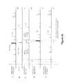
- FIG. 2 bdiagrams A-E illustrate the various blanking signals versus time in accordance with the embodiment described with reference to FIG. 2 a . While FIG. 2 b exemplifies the delay and blanking with reference to the gamma detector, one skilled in the art recognizes that the same concepts apply in the parallel paths for additional detectors (e.g., neutron detector modules N 1 , N 2 , N 3 ).
- additional detectorse.g., neutron detector modules N 1 , N 2 , N 3 .
- diagram Ashows an exemplary gamma detector output signal ( 19 in FIG. 2 a ), containing an unintended X-ray pulse preceded by several “early X-ray pulses”.
- Diagram Bshows the IsXPulse 6 from FIG. 2 a which drives blanking signal 13 with blanking time T B (diagram C).
- diagram Dshows the delay gamma output signal 20 from diagram A after it has been delayed T B by the delay module ( 3 in FIG. 2 a .) and finally diagram E depicts the delayed and blanked gamma detector signal 21 after all unintended pulses (X-ray main pulse and potential “early X-rays”) have been removed from the original detector signal.
- the types of individual detectors referenced in the exemplary system in FIG. 2 amay be used to scan for and detect special nuclear material (SNM) which are used to create atomic weapons, radiological dispersal devices (RDD or “dirty bombs”), and other types of radioactive materials. While the individual systems, and in particular the detectors, are intended to receive and process a specific type of radiation, the individual systems may detect stray signals from other systems operating in proximity thereto. This results in inaccurate performance of the first system, e.g., obscured results, false alarms, etc.
- SNMnuclear material
- RDDradiological dispersal devices
- a more detailed description of the various types of scanning systems that may be utilized in conjunction with the process described hereinis found in one or more of the following United States patents which are incorporated herein by reference in their entirety: U.S. Pat.
- the self blanking methodmay be utilized to blank only the gamma detector.
- the functionality represented and described with reference to FIG. 2 amay be implemented through software, hardware or a combination thereof.
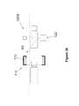
- a more specific example of the dual radiation detection system in FIG. 2 aincludes two different detection systems 110 and 120 A operating in proximity to one another.
- the passive system 110is used to scan all or some portion of the vehicle 112 as it drives between detector panels 114 .
- Exemplary embodiments of system 110include Science Applications International Corporation's EXPLORANIUM AT-980, AT-900, ST-20 and SRM-910 Radiation Portal Monitors.
- system 120 Ais representative of an active scanning system, wherein a x-ray source 122 generates x-rays, e.g., at approximately 5-7 MeV and 8-10 MeV of linac and approximately 5-7.5 MeV range for betatron source, which pass through vehicle 116 and are received at detector 124 .
- the system 120 A in FIG. 3 ais intended to represent a mobile or movable system, such as that shown in FIG. 3A of U.S. Pat. No. 7,408,160, which is incorporated herein by reference and which is physically embodied in commercially available products such as Science Applications International Corporation's VACIS M6500 Mobile Imaging System. It is common for multiple scanning systems such as those described herein to be simultaneously operated within proximity to one another in order to efficiently and effectively monitor the contents of cargo at border crossings, ports or other checkpoints.
- an alternative configurationshows two different detector systems 110 and 120 B, wherein the features and operation of system 110 are identical to those described with reference to FIG. 3 a and the features and operation of system 120 B are identical to those described with reference to 120 A except 120 B is a stationary system.
- systems 110 and 120 Bmay simultaneously operate on different vehicles, but as exemplified by ray R 3 , unintended radiation from source 122 may be detected by one or more detectors 114 .
- the embodiments for identification and blanking as described hereinmay be utilized.
- the detectors 114 of system 110may include different types of individual detectors for detecting emissions having different energies.
- FIG. 1 of this applicationillustrates a detector stand that includes both neutron and gamma ray detectors.
- gamma ray detectorsare sensitive to source generator x-rays such as those generated by source 122 of system 120 A.
- shielding and focusing technologiesare utilized in order to confine the emitted x-ray radiation to a designated scanning area, but these technologies are not perfect.
- detectors 114are sensitive, that is, they are calibrated to measure small amounts of radiation emitted by materials in the passing targets, it is understandable that additional stray radiation from an x-ray source could mask gamma and/or neutron data emitted from a target or cause a false-positive.
- detectors 114may include polyvinyl toluene (PVT) detectors which have been shown to be capable of detecting radiation from both gamma-ray and neutron sources as discussed in the Sandia Report entitled PVT-NG Sensor Final Report printed January 2012 which is incorporated herein by reference in its entirety.
- PVTpolyvinyl toluene
- the processes described hereinwork to process the detected data to identify and remove the unintended radiation per the process described in accordance with the schematic of FIG. 2 a.
- the x-ray pulse discriminatoridentifies various pulse characteristics to determine if the pulse is an unintended x-ray pulse.
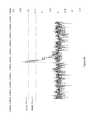
- the signal processing methodologies implemented by the discriminator for identifying the characteristicsutilize anticipated attributes of the unintended impinging radiation in order to selectively remove (or blank) the unintended radiation signals from the detected signals. Referring to FIG. 4 a , it is anticipated that full energy x-ray pulses at, e.g., 6.5 MeV and 9.0 MeV, that are incident on detectors 114 will have amplitudes that are higher than a set threshold. Accordingly, referring back to FIG.
- FIG. 4 aillustrates an exemplary near field direct x-ray signal and shows that the resulting signal has an amplitude that is essentially off the scale and significantly above an intended radiation threshold.
- a far field x-ray signal that is facing a detector 114has an amplitude that is significantly above an intended radiation threshold (see FIG. 4 b ).
- These amplitudes for the unintended x-ray signals as illustrated in FIGS. 4 a and 4 bcan be compared to the amplitudes expected from an intended radiation signals, e.g., gamma ray signals, shown in FIGS. 5 a (high energy) and 5 b (low energy) which are significantly lower.
- scattered x-ray pulseswill likely generate pile-up events when detected by detectors 114 even when they have lost their primary energy, (see FIG. 4 b ).
- the scattered x-ray pulsesrepresent source x-rays that have taken an indirect path to the detector 114 . More specifically, scattered x-rays have encountered a structure, thus changing the attributes of the scattered x-ray signal in one or more ways from the original, un-scattered signal emitted from the source 122 . Accordingly, referring back to FIG.
- Pulse pile-uphappens when pulses arrives closer in time than the pulse resolution time for the detector 114 .
- the detectorreturns inaccurate pulse height information.
- the separate pulsemay be incorrectly viewed as a single pulse when the pulses are very close in time and amplitude will be calculated by adding the two amplitudes, e.g., peak pile-up.
- the detectorcould also record the overlapping signals as two separate events, but calculate incorrect pulse amplitude due to the overlap, e.g., tail pile-up. Since the intended radiation is not expected to produce pile-up since the detectors 114 are tailored to avoid such an phenomenon in the range of the intended radiation, pile-up events can be attributed to unintended radiation and thus removed.
Landscapes
- Physics & Mathematics (AREA)
- Life Sciences & Earth Sciences (AREA)
- General Physics & Mathematics (AREA)
- High Energy & Nuclear Physics (AREA)
- Geophysics (AREA)
- General Life Sciences & Earth Sciences (AREA)
- Health & Medical Sciences (AREA)
- Molecular Biology (AREA)
- Spectroscopy & Molecular Physics (AREA)
- Measurement Of Radiation (AREA)
- Chemical & Material Sciences (AREA)
- Analytical Chemistry (AREA)
- Biochemistry (AREA)
- General Health & Medical Sciences (AREA)
- Immunology (AREA)
- Pathology (AREA)
Abstract
Description
Claims (20)
Priority Applications (5)
| Application Number | Priority Date | Filing Date | Title |
|---|---|---|---|
| US13/672,379US8859981B1 (en) | 2012-11-08 | 2012-11-08 | Method for autonomous self-blanking by radiation portal monitors to minimize the interference from pulsed X-rays radiation |
| US14/487,180US9182515B2 (en) | 2012-11-08 | 2014-09-16 | Method for autonomous self-blanking by radiation portal monitors to minimize the interference from pulsed X-rays radiation |
| US14/935,694US9568637B2 (en) | 2012-11-08 | 2015-11-09 | Method for autonomous self-blanking by radiation portal monitors to minimize the interference from pulsed X-rays radiation |
| US15/409,205US9880315B2 (en) | 2012-11-08 | 2017-01-18 | Method for autonomous self-blanking by radiation portal monitors to minimize the interference from pulsed X-rays radiation |
| US15/882,070US10197700B2 (en) | 2012-11-08 | 2018-01-29 | Method for autonomous self-blanking by radiation portal monitors to minimize the interference from pulsed X-rays radiation |
Applications Claiming Priority (1)
| Application Number | Priority Date | Filing Date | Title |
|---|---|---|---|
| US13/672,379US8859981B1 (en) | 2012-11-08 | 2012-11-08 | Method for autonomous self-blanking by radiation portal monitors to minimize the interference from pulsed X-rays radiation |
Related Child Applications (1)
| Application Number | Title | Priority Date | Filing Date |
|---|---|---|---|
| US14/487,180ContinuationUS9182515B2 (en) | 2012-11-08 | 2014-09-16 | Method for autonomous self-blanking by radiation portal monitors to minimize the interference from pulsed X-rays radiation |
Publications (1)
| Publication Number | Publication Date |
|---|---|
| US8859981B1true US8859981B1 (en) | 2014-10-14 |
Family
ID=51661086
Family Applications (5)
| Application Number | Title | Priority Date | Filing Date |
|---|---|---|---|
| US13/672,379Active2033-04-10US8859981B1 (en) | 2012-11-08 | 2012-11-08 | Method for autonomous self-blanking by radiation portal monitors to minimize the interference from pulsed X-rays radiation |
| US14/487,180Active2032-12-15US9182515B2 (en) | 2012-11-08 | 2014-09-16 | Method for autonomous self-blanking by radiation portal monitors to minimize the interference from pulsed X-rays radiation |
| US14/935,694ActiveUS9568637B2 (en) | 2012-11-08 | 2015-11-09 | Method for autonomous self-blanking by radiation portal monitors to minimize the interference from pulsed X-rays radiation |
| US15/409,205ActiveUS9880315B2 (en) | 2012-11-08 | 2017-01-18 | Method for autonomous self-blanking by radiation portal monitors to minimize the interference from pulsed X-rays radiation |
| US15/882,070ActiveUS10197700B2 (en) | 2012-11-08 | 2018-01-29 | Method for autonomous self-blanking by radiation portal monitors to minimize the interference from pulsed X-rays radiation |
Family Applications After (4)
| Application Number | Title | Priority Date | Filing Date |
|---|---|---|---|
| US14/487,180Active2032-12-15US9182515B2 (en) | 2012-11-08 | 2014-09-16 | Method for autonomous self-blanking by radiation portal monitors to minimize the interference from pulsed X-rays radiation |
| US14/935,694ActiveUS9568637B2 (en) | 2012-11-08 | 2015-11-09 | Method for autonomous self-blanking by radiation portal monitors to minimize the interference from pulsed X-rays radiation |
| US15/409,205ActiveUS9880315B2 (en) | 2012-11-08 | 2017-01-18 | Method for autonomous self-blanking by radiation portal monitors to minimize the interference from pulsed X-rays radiation |
| US15/882,070ActiveUS10197700B2 (en) | 2012-11-08 | 2018-01-29 | Method for autonomous self-blanking by radiation portal monitors to minimize the interference from pulsed X-rays radiation |
Country Status (1)
| Country | Link |
|---|---|
| US (5) | US8859981B1 (en) |
Cited By (2)
| Publication number | Priority date | Publication date | Assignee | Title |
|---|---|---|---|---|
| US20150219785A1 (en)* | 2012-05-21 | 2015-08-06 | Mb Telecom Ltd. | Nonintrusive inspection method and system of cargo type objects: vehicles, container trucks, train carriages |
| US12387900B2 (en) | 2022-02-03 | 2025-08-12 | Rapiscan Holdings, Inc. | Systems and methods for real-time energy and dose monitoring of an X-ray linear accelerator |
Families Citing this family (3)
| Publication number | Priority date | Publication date | Assignee | Title |
|---|---|---|---|---|
| CN105333826B (en)* | 2015-12-04 | 2019-02-22 | 同方威视技术股份有限公司 | Vehicle quick inspection method and system |
| MX2023009276A (en)* | 2021-02-23 | 2023-10-10 | Rapiscan Systems Inc | SYSTEMS AND METHODS FOR ELIMINATING CROSSTALK SIGNALS IN ONE OR MORE SCANNING SYSTEMS THAT HAVE MULTIPLE X-RAY SOURCES. |
| JP2024085815A (en)* | 2022-12-15 | 2024-06-27 | キヤノン株式会社 | RADIATION DETECTOR, DRIVING METHOD FOR RADIATION DETECTOR, AND RADIATION IMAGING SYSTEM |
Citations (19)
| Publication number | Priority date | Publication date | Assignee | Title |
|---|---|---|---|---|
| US4194634A (en)* | 1977-12-09 | 1980-03-25 | Leonard Kelly | Method and apparatus for sorting radioactive material |
| US5077549A (en)* | 1989-08-07 | 1991-12-31 | Shmuel Hershkovitz | Integrating passive infrared intrusion detector |
| US6255654B1 (en) | 1995-10-23 | 2001-07-03 | Science Applications International Corporation | Density detection using discrete photon counting |
| US6507025B1 (en) | 1995-10-23 | 2003-01-14 | Science Applications International Corporation | Density detection using real time discrete photon counting for fast moving targets |
| US20030122084A1 (en)* | 2000-01-18 | 2003-07-03 | Pascal Desaute | Method and apparatus for imaging by means of ionizing radiation |
| US6953937B2 (en)* | 2003-06-26 | 2005-10-11 | Battelle Energy Alliance, Llc | Method and apparatus for the detection of neutrons and gamma rays |
| US7039159B2 (en) | 2004-01-30 | 2006-05-02 | Science Applications International Corporation | Method and system for automatically scanning and imaging the contents of a moving target |
| US7045787B1 (en) | 1995-10-23 | 2006-05-16 | Science Applications International Corporation | Density detection using real time discrete photon counting for fast moving targets |
| US7166844B1 (en) | 2004-06-01 | 2007-01-23 | Science Applications International Corporation | Target density imaging using discrete photon counting to produce high-resolution radiographic images |
| US7352844B1 (en) | 2004-01-30 | 2008-04-01 | Science Applications International Corporation | Method and system for automatically scanning and imaging the contents of a moving target |
| US7388205B1 (en) | 1995-10-23 | 2008-06-17 | Science Applications International Corporation | System and method for target inspection using discrete photon counting and neutron detection |
| US7430479B1 (en) | 2004-08-17 | 2008-09-30 | Science Applications International Corporation | System and method for analyzing content data |
| US7453987B1 (en) | 2004-03-04 | 2008-11-18 | Science Applications International Corporation | Method and system for high energy, low radiation power X-ray imaging of the contents of a target |
| US7596275B1 (en) | 2004-03-01 | 2009-09-29 | Science Applications International Corporation | Methods and systems for imaging and classifying targets as empty or non-empty |
| US7742568B2 (en) | 2007-06-09 | 2010-06-22 | Spectrum San Diego, Inc. | Automobile scanning system |
| US20100181491A1 (en)* | 2009-01-16 | 2010-07-22 | Karim Karim S | Digitizer for a digital imaging system |
| US20130057323A1 (en)* | 2010-05-04 | 2013-03-07 | Stmicroelectronics S.R.I. | Integrated circuit for controlling a switch of a current path with leading edge blanking device of the current signal |
| US8598536B2 (en)* | 2006-10-04 | 2013-12-03 | CERN—European Organization for Nuclear Research | Apparatus and method for medical imaging |
| US8618495B2 (en)* | 2010-05-03 | 2013-12-31 | Brookhaven Science Associates, Llc | Method and apparatus for analog pulse pile-up rejection |
Family Cites Families (6)
| Publication number | Priority date | Publication date | Assignee | Title |
|---|---|---|---|---|
| US4070707A (en)* | 1976-07-12 | 1978-01-24 | General Electric Company | Reduction of offsets in data acquisition systems |
| GB0810638D0 (en)* | 2008-06-11 | 2008-07-16 | Rapiscan Security Products Inc | Photomultiplier and detection systems |
| FR2933498B1 (en)* | 2008-07-04 | 2012-07-06 | Smiths Heimann Sas | METHOD AND DEVICE FOR DETECTING THE PRESENCE, IN A LOAD, OF SUSPICIOUS OBJECTS CONSISTING OF HIGH ATOMIC WEIGHT NUCLEAR MATERIALS |
| US8908831B2 (en)* | 2011-02-08 | 2014-12-09 | Rapiscan Systems, Inc. | Covert surveillance using multi-modality sensing |
| EP3252506B1 (en)* | 2011-02-08 | 2020-11-18 | Rapiscan Systems, Inc. | Covert surveillance using multi-modality sensing |
| US9477005B2 (en)* | 2011-11-07 | 2016-10-25 | Arktis Radiation Detectors Ltd | Method for obtaining information signatures from nuclear material or about the presence, the nature and/or the shielding of a nuclear material and measurement setup for performing such method |
- 2012
- 2012-11-08USUS13/672,379patent/US8859981B1/enactiveActive
- 2014
- 2014-09-16USUS14/487,180patent/US9182515B2/enactiveActive
- 2015
- 2015-11-09USUS14/935,694patent/US9568637B2/enactiveActive
- 2017
- 2017-01-18USUS15/409,205patent/US9880315B2/enactiveActive
- 2018
- 2018-01-29USUS15/882,070patent/US10197700B2/enactiveActive
Patent Citations (29)
| Publication number | Priority date | Publication date | Assignee | Title |
|---|---|---|---|---|
| US4194634A (en)* | 1977-12-09 | 1980-03-25 | Leonard Kelly | Method and apparatus for sorting radioactive material |
| US5077549A (en)* | 1989-08-07 | 1991-12-31 | Shmuel Hershkovitz | Integrating passive infrared intrusion detector |
| US7045787B1 (en) | 1995-10-23 | 2006-05-16 | Science Applications International Corporation | Density detection using real time discrete photon counting for fast moving targets |
| US6507025B1 (en) | 1995-10-23 | 2003-01-14 | Science Applications International Corporation | Density detection using real time discrete photon counting for fast moving targets |
| US6552346B2 (en) | 1995-10-23 | 2003-04-22 | Science Applications International Corporation | Density detection using discrete photon counting |
| US6255654B1 (en) | 1995-10-23 | 2001-07-03 | Science Applications International Corporation | Density detection using discrete photon counting |
| US7408160B2 (en) | 1995-10-23 | 2008-08-05 | Science Applications International Corporation | Density detection using real time discrete photon counting for fast moving targets |
| US7365332B2 (en) | 1995-10-23 | 2008-04-29 | Science Applications International Corporation | Density detection using real time discrete photon counting for fast moving targets |
| US7388205B1 (en) | 1995-10-23 | 2008-06-17 | Science Applications International Corporation | System and method for target inspection using discrete photon counting and neutron detection |
| US7368717B2 (en) | 1995-10-23 | 2008-05-06 | Science Applications International Corporation | Density detection using real time discrete photon counting for fast moving targets |
| US7335887B1 (en) | 1995-10-23 | 2008-02-26 | Science Applications International Corporation | System and method for target inspection using discrete photon counting and neutron detection |
| US20030122084A1 (en)* | 2000-01-18 | 2003-07-03 | Pascal Desaute | Method and apparatus for imaging by means of ionizing radiation |
| US6600161B2 (en)* | 2000-01-18 | 2003-07-29 | Biospace Instruments | Method and apparatus for imaging by means of ionizing radiation |
| US6953937B2 (en)* | 2003-06-26 | 2005-10-11 | Battelle Energy Alliance, Llc | Method and apparatus for the detection of neutrons and gamma rays |
| US7215738B2 (en) | 2004-01-30 | 2007-05-08 | Science Applications International Corporation | Method and system for automatically scanning and imaging the contents of a moving target |
| US7352844B1 (en) | 2004-01-30 | 2008-04-01 | Science Applications International Corporation | Method and system for automatically scanning and imaging the contents of a moving target |
| US7039159B2 (en) | 2004-01-30 | 2006-05-02 | Science Applications International Corporation | Method and system for automatically scanning and imaging the contents of a moving target |
| US7596275B1 (en) | 2004-03-01 | 2009-09-29 | Science Applications International Corporation | Methods and systems for imaging and classifying targets as empty or non-empty |
| US7453987B1 (en) | 2004-03-04 | 2008-11-18 | Science Applications International Corporation | Method and system for high energy, low radiation power X-ray imaging of the contents of a target |
| US7166844B1 (en) | 2004-06-01 | 2007-01-23 | Science Applications International Corporation | Target density imaging using discrete photon counting to produce high-resolution radiographic images |
| US7388209B1 (en) | 2004-06-01 | 2008-06-17 | Science Applications International Corporation | Target density imaging using discrete photon counting to produce high-resolution radiographic images |
| US7430479B1 (en) | 2004-08-17 | 2008-09-30 | Science Applications International Corporation | System and method for analyzing content data |
| US8598536B2 (en)* | 2006-10-04 | 2013-12-03 | CERN—European Organization for Nuclear Research | Apparatus and method for medical imaging |
| US7742568B2 (en) | 2007-06-09 | 2010-06-22 | Spectrum San Diego, Inc. | Automobile scanning system |
| US7957506B2 (en) | 2007-06-09 | 2011-06-07 | Spectrum San Diego, Inc. | Automobile scanning system |
| US8116431B2 (en) | 2007-06-09 | 2012-02-14 | Spectrum San Diego, Inc. | Automobile scanning system |
| US20100181491A1 (en)* | 2009-01-16 | 2010-07-22 | Karim Karim S | Digitizer for a digital imaging system |
| US8618495B2 (en)* | 2010-05-03 | 2013-12-31 | Brookhaven Science Associates, Llc | Method and apparatus for analog pulse pile-up rejection |
| US20130057323A1 (en)* | 2010-05-04 | 2013-03-07 | Stmicroelectronics S.R.I. | Integrated circuit for controlling a switch of a current path with leading edge blanking device of the current signal |
Non-Patent Citations (1)
| Title |
|---|
| U.S. Appl. No. 11/033,552, filed Jan. 12, 2005, Vourvopoulos, et al. |
Cited By (3)
| Publication number | Priority date | Publication date | Assignee | Title |
|---|---|---|---|---|
| US20150219785A1 (en)* | 2012-05-21 | 2015-08-06 | Mb Telecom Ltd. | Nonintrusive inspection method and system of cargo type objects: vehicles, container trucks, train carriages |
| US9625607B2 (en)* | 2012-05-21 | 2017-04-18 | Mb Telecom Ltd. | Nonintrusive inspection method and system of cargo type objects: vehicles, container trucks, train carriages |
| US12387900B2 (en) | 2022-02-03 | 2025-08-12 | Rapiscan Holdings, Inc. | Systems and methods for real-time energy and dose monitoring of an X-ray linear accelerator |
Also Published As
| Publication number | Publication date |
|---|---|
| US20160070020A1 (en) | 2016-03-10 |
| US20180217291A1 (en) | 2018-08-02 |
| US10197700B2 (en) | 2019-02-05 |
| US9880315B2 (en) | 2018-01-30 |
| US20170123100A1 (en) | 2017-05-04 |
| US9568637B2 (en) | 2017-02-14 |
| US9182515B2 (en) | 2015-11-10 |
| US20150234082A1 (en) | 2015-08-20 |
Similar Documents
| Publication | Publication Date | Title |
|---|---|---|
| US10197700B2 (en) | Method for autonomous self-blanking by radiation portal monitors to minimize the interference from pulsed X-rays radiation | |
| US11307325B2 (en) | Covert surveillance using multi-modality sensing | |
| US9207195B2 (en) | High-energy X-ray-spectroscopy-based inspection system and methods to determine the atomic number of materials | |
| US8433036B2 (en) | Scanning systems | |
| US7453987B1 (en) | Method and system for high energy, low radiation power X-ray imaging of the contents of a target | |
| US8457274B2 (en) | System and methods for intrapulse multi-energy and adaptive multi-energy X-ray cargo inspection | |
| CN101210894B (en) | System and method capable of simultaneously performing radiation imaging inspection and radioactive substance monitoring | |
| EP2539902A2 (en) | Systems and methods for detecting nuclear material | |
| CN101581679A (en) | Method and system for detecting special nuclear material | |
| US9678224B2 (en) | System and method for detecting neutron, gamma and muon radiations with contiguous plastics scintillators | |
| US11867866B2 (en) | System and method for fissionable material detection with a short pulse neutron source | |
| US20250155590A1 (en) | Method for determining the neutron flux by using a portable radionuclide identification device (rid) comprising scintillation material with iodine | |
| WO2015020710A2 (en) | Integrated primary and special nuclear material alarm resolution | |
| Langeveld et al. | Implementation of Noise Spectroscopy using biased large-area photodiodes | |
| US8610080B2 (en) | Method for determining the spectral and spatial distribution of braking photons, and related device | |
| US11061164B1 (en) | System, algorithm, and method using short pulse interrogation with neutrons to detect and identify matter | |
| WO2024097695A1 (en) | Systems and methods for reducing interference in radiation portal monitors | |
| Schwellenbach et al. | Passive imaging of warhead-like configurations with cosmic-ray muon tracking scanners | |
| EP3797321A1 (en) | System and method for fissionable material detection with a short pulse neutron source | |
| WO2011068577A1 (en) | Systems, methods, and computer-readable media for explosive detection |
Legal Events
| Date | Code | Title | Description |
|---|---|---|---|
| AS | Assignment | Owner name:SCIENCE APPLICATIONS INTERNATIONAL CORPORATION, CA Free format text:ASSIGNMENT OF ASSIGNORS INTEREST;ASSIGNORS:STOIAN, ADRIAN;GREENWOOD, GREGORY ALAN;REEL/FRAME:029266/0643 Effective date:20121107 | |
| AS | Assignment | Owner name:LEIDOS, INC., VIRGINIA Free format text:CHANGE OF NAME;ASSIGNOR:SCIENCE APPLICATIONS INTERNATIONAL CORPORATION;REEL/FRAME:032711/0423 Effective date:20130927 | |
| STCF | Information on status: patent grant | Free format text:PATENTED CASE | |
| AS | Assignment | Owner name:CITIBANK, N.A., DELAWARE Free format text:SECURITY INTEREST;ASSIGNOR:LEIDOS, INC.;REEL/FRAME:039809/0801 Effective date:20160816 Owner name:CITIBANK, N.A., DELAWARE Free format text:SECURITY INTEREST;ASSIGNOR:LEIDOS, INC.;REEL/FRAME:039818/0272 Effective date:20160816 | |
| MAFP | Maintenance fee payment | Free format text:PAYMENT OF MAINTENANCE FEE, 4TH YEAR, LARGE ENTITY (ORIGINAL EVENT CODE: M1551) Year of fee payment:4 | |
| AS | Assignment | Owner name:LEIDOS, INC., VIRGINIA Free format text:RELEASE BY SECURED PARTY;ASSIGNOR:CITIBANK, N.A., AS COLLATERAL AGENT;REEL/FRAME:051632/0819 Effective date:20200117 Owner name:LEIDOS, INC., VIRGINIA Free format text:RELEASE BY SECURED PARTY;ASSIGNOR:CITIBANK, N.A., AS COLLATERAL AGENT;REEL/FRAME:051632/0742 Effective date:20200117 | |
| MAFP | Maintenance fee payment | Free format text:PAYMENT OF MAINTENANCE FEE, 8TH YEAR, LARGE ENTITY (ORIGINAL EVENT CODE: M1552); ENTITY STATUS OF PATENT OWNER: LARGE ENTITY Year of fee payment:8 |