US8858600B2 - Dynamic spinal stabilization device - Google Patents
Dynamic spinal stabilization deviceDownload PDFInfo
- Publication number
- US8858600B2 US8858600B2US12/103,576US10357608AUS8858600B2US 8858600 B2US8858600 B2US 8858600B2US 10357608 AUS10357608 AUS 10357608AUS 8858600 B2US8858600 B2US 8858600B2
- Authority
- US
- United States
- Prior art keywords
- component
- stabilization device
- cavity
- motion
- spinal
- Prior art date
- Legal status (The legal status is an assumption and is not a legal conclusion. Google has not performed a legal analysis and makes no representation as to the accuracy of the status listed.)
- Expired - Fee Related
Links
Images


Classifications
- A—HUMAN NECESSITIES
- A61—MEDICAL OR VETERINARY SCIENCE; HYGIENE
- A61B—DIAGNOSIS; SURGERY; IDENTIFICATION
- A61B17/00—Surgical instruments, devices or methods
- A61B17/56—Surgical instruments or methods for treatment of bones or joints; Devices specially adapted therefor
- A61B17/58—Surgical instruments or methods for treatment of bones or joints; Devices specially adapted therefor for osteosynthesis, e.g. bone plates, screws or setting implements
- A61B17/68—Internal fixation devices, including fasteners and spinal fixators, even if a part thereof projects from the skin
- A61B17/70—Spinal positioners or stabilisers, e.g. stabilisers comprising fluid filler in an implant
- A61B17/7001—Screws or hooks combined with longitudinal elements which do not contact vertebrae
- A61B17/7002—Longitudinal elements, e.g. rods
- A61B17/7019—Longitudinal elements having flexible parts, or parts connected together, such that after implantation the elements can move relative to each other
- A61B17/7023—Longitudinal elements having flexible parts, or parts connected together, such that after implantation the elements can move relative to each other with a pivot joint
- A—HUMAN NECESSITIES
- A61—MEDICAL OR VETERINARY SCIENCE; HYGIENE
- A61B—DIAGNOSIS; SURGERY; IDENTIFICATION
- A61B17/00—Surgical instruments, devices or methods
- A61B17/56—Surgical instruments or methods for treatment of bones or joints; Devices specially adapted therefor
- A61B17/58—Surgical instruments or methods for treatment of bones or joints; Devices specially adapted therefor for osteosynthesis, e.g. bone plates, screws or setting implements
- A61B17/68—Internal fixation devices, including fasteners and spinal fixators, even if a part thereof projects from the skin
- A61B17/70—Spinal positioners or stabilisers, e.g. stabilisers comprising fluid filler in an implant
- A61B17/7001—Screws or hooks combined with longitudinal elements which do not contact vertebrae
- A61B17/7002—Longitudinal elements, e.g. rods
- A61B17/7014—Longitudinal elements, e.g. rods with means for adjusting the distance between two screws or hooks
- A—HUMAN NECESSITIES
- A61—MEDICAL OR VETERINARY SCIENCE; HYGIENE
- A61B—DIAGNOSIS; SURGERY; IDENTIFICATION
- A61B17/00—Surgical instruments, devices or methods
- A61B17/56—Surgical instruments or methods for treatment of bones or joints; Devices specially adapted therefor
- A61B17/58—Surgical instruments or methods for treatment of bones or joints; Devices specially adapted therefor for osteosynthesis, e.g. bone plates, screws or setting implements
- A61B17/68—Internal fixation devices, including fasteners and spinal fixators, even if a part thereof projects from the skin
- A61B17/70—Spinal positioners or stabilisers, e.g. stabilisers comprising fluid filler in an implant
- A61B17/7001—Screws or hooks combined with longitudinal elements which do not contact vertebrae
- A61B17/7002—Longitudinal elements, e.g. rods
- A61B17/7019—Longitudinal elements having flexible parts, or parts connected together, such that after implantation the elements can move relative to each other
- A61B17/7025—Longitudinal elements having flexible parts, or parts connected together, such that after implantation the elements can move relative to each other with a sliding joint
- A—HUMAN NECESSITIES
- A61—MEDICAL OR VETERINARY SCIENCE; HYGIENE
- A61B—DIAGNOSIS; SURGERY; IDENTIFICATION
- A61B17/00—Surgical instruments, devices or methods
- A61B17/56—Surgical instruments or methods for treatment of bones or joints; Devices specially adapted therefor
- A61B17/58—Surgical instruments or methods for treatment of bones or joints; Devices specially adapted therefor for osteosynthesis, e.g. bone plates, screws or setting implements
- A61B17/68—Internal fixation devices, including fasteners and spinal fixators, even if a part thereof projects from the skin
- A61B17/70—Spinal positioners or stabilisers, e.g. stabilisers comprising fluid filler in an implant
- A61B17/7062—Devices acting on, attached to, or simulating the effect of, vertebral processes, vertebral facets or ribs ; Tools for such devices
- A61B17/7064—Devices acting on, attached to, or simulating the effect of, vertebral facets; Tools therefor
- A—HUMAN NECESSITIES
- A61—MEDICAL OR VETERINARY SCIENCE; HYGIENE
- A61B—DIAGNOSIS; SURGERY; IDENTIFICATION
- A61B17/00—Surgical instruments, devices or methods
- A61B17/56—Surgical instruments or methods for treatment of bones or joints; Devices specially adapted therefor
- A61B17/58—Surgical instruments or methods for treatment of bones or joints; Devices specially adapted therefor for osteosynthesis, e.g. bone plates, screws or setting implements
- A61B17/68—Internal fixation devices, including fasteners and spinal fixators, even if a part thereof projects from the skin
- A61B17/70—Spinal positioners or stabilisers, e.g. stabilisers comprising fluid filler in an implant
- A61B17/7001—Screws or hooks combined with longitudinal elements which do not contact vertebrae
- A61B17/7002—Longitudinal elements, e.g. rods
- A61B17/7004—Longitudinal elements, e.g. rods with a cross-section which varies along its length
- A—HUMAN NECESSITIES
- A61—MEDICAL OR VETERINARY SCIENCE; HYGIENE
- A61B—DIAGNOSIS; SURGERY; IDENTIFICATION
- A61B17/00—Surgical instruments, devices or methods
- A61B17/56—Surgical instruments or methods for treatment of bones or joints; Devices specially adapted therefor
- A61B17/58—Surgical instruments or methods for treatment of bones or joints; Devices specially adapted therefor for osteosynthesis, e.g. bone plates, screws or setting implements
- A61B17/68—Internal fixation devices, including fasteners and spinal fixators, even if a part thereof projects from the skin
- A61B17/70—Spinal positioners or stabilisers, e.g. stabilisers comprising fluid filler in an implant
- A61B17/7001—Screws or hooks combined with longitudinal elements which do not contact vertebrae
- A61B17/7032—Screws or hooks with U-shaped head or back through which longitudinal rods pass
- A—HUMAN NECESSITIES
- A61—MEDICAL OR VETERINARY SCIENCE; HYGIENE
- A61B—DIAGNOSIS; SURGERY; IDENTIFICATION
- A61B17/00—Surgical instruments, devices or methods
- A61B17/56—Surgical instruments or methods for treatment of bones or joints; Devices specially adapted therefor
- A61B17/58—Surgical instruments or methods for treatment of bones or joints; Devices specially adapted therefor for osteosynthesis, e.g. bone plates, screws or setting implements
- A61B17/68—Internal fixation devices, including fasteners and spinal fixators, even if a part thereof projects from the skin
- A61B17/70—Spinal positioners or stabilisers, e.g. stabilisers comprising fluid filler in an implant
- A61B17/7001—Screws or hooks combined with longitudinal elements which do not contact vertebrae
- A61B17/7041—Screws or hooks combined with longitudinal elements which do not contact vertebrae with single longitudinal rod offset laterally from single row of screws or hooks
- A—HUMAN NECESSITIES
- A61—MEDICAL OR VETERINARY SCIENCE; HYGIENE
- A61B—DIAGNOSIS; SURGERY; IDENTIFICATION
- A61B17/00—Surgical instruments, devices or methods
- A61B17/56—Surgical instruments or methods for treatment of bones or joints; Devices specially adapted therefor
- A61B17/58—Surgical instruments or methods for treatment of bones or joints; Devices specially adapted therefor for osteosynthesis, e.g. bone plates, screws or setting implements
- A61B17/68—Internal fixation devices, including fasteners and spinal fixators, even if a part thereof projects from the skin
- A61B17/70—Spinal positioners or stabilisers, e.g. stabilisers comprising fluid filler in an implant
- A61B17/7049—Connectors, not bearing on the vertebrae, for linking longitudinal elements together
- A—HUMAN NECESSITIES
- A61—MEDICAL OR VETERINARY SCIENCE; HYGIENE
- A61F—FILTERS IMPLANTABLE INTO BLOOD VESSELS; PROSTHESES; DEVICES PROVIDING PATENCY TO, OR PREVENTING COLLAPSING OF, TUBULAR STRUCTURES OF THE BODY, e.g. STENTS; ORTHOPAEDIC, NURSING OR CONTRACEPTIVE DEVICES; FOMENTATION; TREATMENT OR PROTECTION OF EYES OR EARS; BANDAGES, DRESSINGS OR ABSORBENT PADS; FIRST-AID KITS
- A61F2/00—Filters implantable into blood vessels; Prostheses, i.e. artificial substitutes or replacements for parts of the body; Appliances for connecting them with the body; Devices providing patency to, or preventing collapsing of, tubular structures of the body, e.g. stents
- A61F2/02—Prostheses implantable into the body
- A61F2/30—Joints
- A61F2/44—Joints for the spine, e.g. vertebrae, spinal discs
- A61F2/442—Intervertebral or spinal discs, e.g. resilient
Definitions
- the present inventionrelates generally to spinal prostheses, and more particularly, towards a method and system for stabilization of a spinal segment.
- a spinal segmentincludes a lumbar disc and two facet joints. Degenerative changes in the disc can lead to changes in the facet joint, and vice versa. In order to treat a degenerative condition and to alleviate the pain involved with such a malady, surgical methods may be employed to replace the degenerative component of the spinal segment, such as the damaged disc. However, the replacement of a degenerative disc may not suffice, as the facet joint components of the spinal column may still be a source of discomfort and/or limited mobility. As such, it may desirable to replace a degenerative or problematic facet joint with a posterior stabilization device.
- the degenerative processmay result in a condition called spinal stenosis, where there is a narrowing of the spinal canal. This is caused by a combination of reduced disc height, ligamnetum hypertrophy, a forward slip of the vertebra and disc bulging.
- Surgeryis sometime needed to deal with this condition, where a surgical procedure may involve decompression of the spine and/or the removal of posterior portions of the spinal column. This often makes the spine unstable, requiring stabilization of the spine after the decompression.
- Such stabilizationmay be achieved with an instrumented postero-lateral fusion, where pedicle screws are inserted into the vertebra to be fused and connected with rods or plates, and bone is laid on the side of the spine over the transverse processes.
- Stabilizationmay also be accomplished by a dynamic stabilization device where there is no need to add a fusion, and the device stabilizes the spine.
- a posterior dynamic stabilization deviceis typically attached to pedicle screws inserted in to the vertebrae, however, conventional devices are limited in their allowable range of motion and results may vary from patient to patient. It would be desirable to allow the surgeon to select or otherwise adjust the amount of motion desired in the stabilization device based on the requirements of the individual patient.
- each motion segment of the spinemoves around an instantaneous center of rotation.
- the instantaneous axis of rotationis the axis perpendicular to the plane of motion passing through a point in the body that does not move.
- this pointis basically the point at which the motion segment rotates about, also termed the center of rotation.
- a stabilization devicewhich results in a minimum reduction in the natural movement of a motion segment of the spinal column when implanted, thereby reducing any additional strain on the adjacent level of the spinal segment of the individual receiving the stabilization device.
- a stabilization deviceable to resist and/or dampen the flexion and extension forces experienced by the motion segment during movement, while providing limited motion in the desired directions.
- a stabilization devicehaving an adjustable path of motion that can be selectively adjusted for a particular patient or application.
- the present inventionprovides a dynamic stabilization device providing a minimum reduction in the natural movement of the motion segment and reducing any additional strain on the adjacent level of the spinal column in the individual receiving the stabilization device. Moreover, the present invention provides a dynamic stabilization device able to also resist and/or dampen the flexion and extension forces experienced by the motion segment during movement.
- the dynamic stabilization devicemay further provide an arcuate or angular path of movement that closely approximates the arc of motion of a healthy lumbar segment, while also having a selectively adjustable path of motion for a particular application or patient.
- the present inventionprovides a dynamic stabilization device which can continuously adjust to a moving centre of rotation of an intervertebral disc prosthesis, or that of the lumbar disc anteriorly.
- the present inventionprovides a dynamic stabilization device positionable about a portion of a spinal column.
- the stabilization devicegenerally includes a first component and a second component, where the first and second components are movably coupled to one another to define an arcuate path of motion therebetween which may be selectively adjusted for a particular application.
- the first componentmay include a body defining an opening providing access to a first cavity or recessed region, where the first cavity is able to receive an articulating portion of the second component.
- the first and/or second componentsmay further define one or more openings for the insertion or placement of an adjustment element that may be used to manipulate or otherwise modify the path of motion between the first and second components.
- the stabilization devicemay also include one or more adjustment elements positionable within first and second adjustment openings to affect the path of motion between the first and second components and/or the behavior and characteristics of the movement.
- one or more resistive elementsmay be adjustably positionable within either and/or both of the first and second adjustment openings to provide resistance and/or dampening of the forces experienced as the first and second components move relative to one another.
- the stabilization devicemay further provide multiple degrees of freedom of movement to compensate for inaccuracies experienced during implantation and/or to allow the device to adapt to movements of a spinal segment.
- the stabilization devicemay also include one or more attachment elements for facilitating affixation of the device to the spinal segment.
- the present inventionfurther provides a spinal stabilization device positionable about a posterior side of a spinal segment, including a first component defining a cavity therein; a second component slidably positionable within the cavity of the first component; a first adjustment element movably positioned within the cavity to affect a range of motion between the first and second components; and a second adjustment element movably positioned within the cavity to affect the range of motion between the first and second components.
- the devicemay include a first actuating element movably coupled to an exterior surface of the first component, where the first actuating element is engaged to the first adjustment element for movement thereof, and a second actuating element movably coupled to an exterior surface of the first component, where the second actuating element is engaged to the second adjustment element for movement thereof.
- One or more resistive elementsmay be coupled to the second component to resist movement thereof, and the resistive elements may include a conical spring positioned within the cavity of the first component.
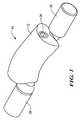
- FIG. 1is a perspective view of an embodiment of a spinal stabilization device in accordance with the present invention
- FIG. 2is an assembly view of an embodiment of a spinal stabilization device in accordance with the present invention
- FIG. 3is a cross-sectional view of an embodiment of a spinal stabilization device in accordance with the present invention.
- FIG. 4is an additional perspective view of an embodiment of a spinal stabilization device in accordance with the present invention.
- FIG. 5is an illustrative view of a portion of an embodiment of a spinal stabilization device in accordance with the present invention.
- FIG. 6is a side view of an embodiment of a spinal stabilization device in accordance with the present invention.
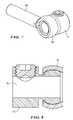
- FIG. 7is a perspective view of an embodiment of a connector element of a spinal stabilization device in accordance with the present invention.
- FIG. 8is a cross-sectional view of an embodiment of a connector element of a spinal stabilization device in accordance with the present invention.
- FIG. 9is a perspective view of an embodiment of a spinal stabilization device in accordance with the present invention.
- FIG. 10is an additional perspective view of the spinal stabilization device of FIG. 9 ;
- FIG. 11is a side view of the spinal stabilization device of FIG. 9 ;
- FIG. 12is a cross-sectional view of the spinal stabilization device of FIG. 9 ;
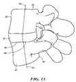
- FIG. 13is a side view of a segment of a spinal column
- FIG. 14is a perspective view of an embodiment of a spinal stabilization device positioned about a segment of a spinal column in accordance with the present invention.
- FIG. 15is a side view of an embodiment of a spinal stabilization device positioned about a segment of a spinal column in accordance with the present invention.
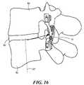
- FIG. 16is an additional side view of an embodiment of a spinal stabilization device positioned about a segment of a spinal column in accordance with the present invention.
- FIG. 17is another side view of an embodiment of a spinal stabilization device positioned about a segment of a spinal column in accordance with the present invention.
- the present inventionprovides a dynamic stabilization device 10 positionable about a portion of a spinal column.
- the present inventionprovides a stabilization device 10 generally including a first component 12 and a second component 14 , where the first and second components are movably coupled to one another to define a range or path of motion therebetween.
- path of motionis intended to include a length, distance and/or shape associated with the movement of either and/or both the first and second components.
- the motion of the first and second componentsmay include an arcuate path about which the first and second components are able to articulate, where the arcuate path may define a point of rotation about which the first and second components move.
- the first component 12may include a body defining an opening providing access to a first cavity or recessed region 16 , where the first cavity 16 is able to receive at least a portion of the second component 14 .
- the body of the first component 12may further include a second cavity 18 or channel adjacent to or otherwise in proximity to the first cavity 16 , where a portion of the first and second cavities may be coupled or otherwise in fluid communication with each other.
- the first and second cavitiesmay include contoured or arcuate walls extending along at least a portion of their respective lengths.
- the first component 12may be constructed as a unitary element, or alternatively, be composed of multiple parts that are fused, welded, or otherwise assembled together to form the desired characteristics and features of the component.
- the first component 12may include a first housing element 12 ′ and a second housing element 12 ′′ that may be fitted or otherwise coupled together.
- the first component 12may be constructed from a myriad of biocompatible materials, including metals, plastics, and polymers as is known in the art.
- the second component 14may define a body having an articulating portion 20 positionable within or otherwise movable about the first component 12 , where the articulating portion 20 may define an arcuate or contoured shape.
- the articulating portion 20 of the second component 14may be movably positionable within the first cavity 16 of the first component 12 .
- the arcuate and/or contoured shapes of both the articulating portion of the second component 14 as well as the walls of the first cavity of the first component 12may provide an arcuate path or range of motion between the two.
- the body of the second component 14may further include a protrusion 22 extending from the articulating portion, where the protrusion 22 is positionable within the second cavity 18 of the first component 12 .
- the body of the first and/or second componentsmay further define one or more openings for the insertion or placement of an adjustment element that may be used to manipulate or otherwise modify the path of motion between the first and second components.
- first and second adjustment openings 24 , 24 ′may be included on either end of the first component 12 about the first and second cavities providing access thereto.
- the stabilization device 10may include one or more adjustment elements 26 , 26 ′ positionable within the first and second adjustment openings 24 , 24 ′ to affect the path of motion between the first and second components and/or the behavior and characteristics of the movement.
- the stabilization device 10may include one or more set screws that can be adjustably positioned within either and/or both of the first and second adjustment openings to reduce or enlarge the path of motion between the first and second components.
- the set screwsmay be positioned at a desired location within the first component 12 to provide a stop against which the second component 14 comes into contact with during movement to prevent and/or restrict further movement.
- one or more resistive elements 28 , 28 ′ and/or one or more dampening elements 30 , 30 ′may be adjustably positionable within either and/or both of the first and second adjustment openings to provide resistance and/or dampening of the forces experienced as the first and second components move relative to one another.
- the resistive or dampening elementsmay include springs, washers, a dashpot mechanism, or the like to provide the desired movement characteristics.
- the stabilization device 10may further provide one or more degrees of freedom of movement to compensate for inaccuracies experienced during implantation and/or to allow the device to adapt to movements of a spinal segment, including the ability to allow flexion/extension, lateral bending, and axial rotation.
- the stabilization device 10may include a joint element 32 movably coupled to one of the first or second components, where the joint element 32 may also include a portion extending from the first and/or second components for attachment to an affixation device or the like.
- the joint element 32may include a rounded portion 34 that forms a ball-and-socket joint with either of the first and second components, or may alternatively include a hinge or other movable construct providing one or more degrees-of-freedom of movement.
- the stabilization device 10may also include one or more attachment elements 36 , 36 ′ for facilitating affixation to the spinal segment.
- the attachment elements 36 , 36 ′may include a cylindrical element or extension coupled to either and/or both of the first and second components, where the attachment elements 36 , 36 ′ may be matable with a pedicle screw or other affixation element for implantation of the stabilization device 10 on a spinal segment.
- a stabilization device 50including a first component 52 and a second component 54 movably coupled to one another to define a path of motion therebetween, where the path of motion may provide an arcuate path about which the first and second components are able to articulate.
- the first component 52may include a body defining an opening providing access to a first cavity or recessed region for receiving at least a portion of the second component 54 .
- the second component 54may define a body having an articulating portion positionable within or otherwise movable about the first component, where the articulating portion may define an arcuate or contoured shape.
- the articulating portion of the second component 54may be movably positionable within the first cavity of the first component 52 .
- the arcuate and/or contoured shapes of both the articulating portion of the second component as well as the walls of the first cavity of the first componentmay provide an arcuate path or range of motion between the two.
- the body of the second componentmay further include a first protrusion 56 extending from the articulating portion, as well as a second protrusion 58 extending from the articulating portion, where both protrusions are positionable within a portion of the first component 52 .
- the body of the first and/or second componentsmay further define one or more openings for the insertion or placement of an adjustment element that may be used to manipulate or otherwise modify the path of motion between the first and second components.
- first and second adjustment openings 60 , 60 ′may be included on either end of the first component providing access to an interior thereof.
- the stabilization devicemay include one or more adjustment elements 62 , 62 ′ positionable within the first and second adjustment openings to affect the path of motion between the first and second components and/or the behavior and characteristics of the movement.
- the stabilization devicemay include one or more set screws that can be adjustably positioned within either and/or both of the first and second adjustment openings to reduce or enlarge the path of motion between the first and second components.
- the set screwsmay be positioned at a desired location within the first component to provide a stop against which the first and second protrusions of the second component 54 come into contact with during movement to prevent and/or restrict further movement.
- the path of motionmay be adjustable from a length of 0 mm, where motion is restricted, to approximately 8 mm in a particular direction.
- the stabilization device 50may also include one or more attachment elements for facilitating affixation to the spinal segment.
- first and second attachment elements 64 , 64 ′may include cylindrical bodies or extensions coupled to either and/or both of the first and second components, where the attachment elements 64 , 64 ′ may be matable with a pedicle screw or other intermediate elements for implantation of the stabilization device on a spinal segment.
- the stabilization device 50may include one or more connector elements movably positionable about the one or more attachment elements 64 , 64 ′ for affixation to a spinal segment.
- First and second connector elements 66 , 66 ′may be included, where the connector elements define collar portions 68 , 68 ′ having an opening therethrough for movably coupling the connector elements to the first and second attachment elements, respectively.
- the collar portions 68 , 68 ′may include an opening for the insertion of a set screw, which may be adjusted to tighten the collar about the attachment element once the desired positioning has been achieved.
- the stabilization device 50may further include a bearing connector 70 engageable with either and/or both of the connector elements to provide for additional movement capabilities between the stabilization device and a spinal segment.
- the bearing connector 70may define an opening 72 therethrough for the passage of either the first or second attachment elements.
- the bearing connector 70may further movably couple to the connector element 66 as to form a ball-and-socket joint, thereby allowing the attachment element, and thus the first and second components of the stabilization device, to move and adjust to the forces and motion of a spinal segment, including flexion/extension, lateral bending, and axial rotation.
- the stabilization device 100generally includes a first component 102 and a second component 104 , where the first and second components are movably coupled to one another to define a range or path of motion therebetween.
- the first component 102may include a body defining an opening providing access to a cavity 106 , where the cavity 106 is able to receive at least a portion of the second component 104 for movement relative to one another.
- the second component 104may define a body having an articulating portion or segment 108 positionable within or otherwise movable about the first component 102 , such as within the cavity 106 , and the articulating portion 108 may define a flared end that is slidable throughout a length of the cavity 106 during flexion and/or extension movements once the device is implanted.
- the spinal stabilization device 100may further include one or more adjustment elements that may be used to manipulate or otherwise modify the available range of motion between the first and second components.
- one or more adjustment elements 110 , 110 ′may be coupled to at least one of the first and second components to provide a physical stop or abutment that limits the range of motion between the first and second components and/or the behavior and characteristics of the movement.
- the adjustment elements 110 , 100 ′may include stoppers that are slidable or otherwise selectively positionable in the cavity 106 of the first component 104 on either side of the flared end of the second component 104 , where the stoppers include a surface that contacts or otherwise abuts a portion of the second component 104 at an upper and/or lower end of a selected range of movement in either direction.
- One or more adjustment actuation components 112 , 112 ′may be operably coupled to the adjustment elements 110 , 100 ′, respectively, for the manipulation and selective adjustment thereof.
- the adjustment actuation components 112 , 112 ′may be coupled to an exterior surface of the first component 102 such that manipulation of either of the adjustment actuation components 112 , 112 ′ affects the movement and/or positioning of the adjustment elements 110 , 100 ′ to provide a desired range of motion between the first and second components.
- each of the adjustment actuation components 112 , 112 ′may include a thumbwheel or similar manually adjustable mechanism that interacts with the actuation components 112 , 112 ′ to provide the desired positioning within the cavity 106 of the first component 104 .
- the thumbwheelsmay have a threaded interior surface that mechanically engages a threaded portion of the actuation components 112 , 112 ′ to move the actuation components 112 , 112 ′ along the length of the cavity 106 to thus define the desired range of motion.
- one or more resistive elements 114 , 114 ′may be adjustably positionable within either and/or both of the first and second adjustment openings to provide resistance and/or dampening of the forces experienced as the first and second components move relative to one another.
- the resistive or dampening elementsmay include springs, washers, a dashpot mechanism, or the like to provide the desired movement characteristics.
- the resistive elements 114 , 114 ′may be positioned within the cavity of the first component 102 on either side of a portion of the second component 104 to provide the desired resistance and/or movement characteristics between the first and second components in multiple directions, such as flexion and extension for example.
- each resistive elementmay include a conical spring collapsible to a single ring or circumference of the spring.
- a conical springhaving such collapsible characteristics, the overall size of stabilization device 100 may be significantly reduced compared to a device having a typical cylindrically-shaped spring, which is only collapsible to an overall length or size of all the rings or circumferences positioned adjacent one another.
- the size differentialbecomes increasingly significant when dealing with spinal implants, such as those disclosed herein, which may have sizes and motion ranges measured in millimeters.
- such a resistive elementcan still provide resistance across a large range of motion while minimizing the actual length or size that the spring would otherwise take up within the cavity 106 of the first component 104 , for example.
- the stabilization devices described abovemay be positioned about a portion of a spinal segment.
- the human spineconsists of multiple spinal segments, with a spinal segment having first and second vertebral bodies 80 , 82 , respectively, with an intervertebral disc 84 located therebetween, as shown in FIG. 13 .
- the spinal segmenttypically includes a vertebral endplate 86 , which is a thin layer of cartilage located between the vertebral body and the intervertebral disc.
- the vertebral bodiesinclude both an anterior portion 88 and a posterior portion 90 corresponding to the “front” end and “back” end, respectively, of the spinal column as is known in the art.
- Each of the first and second vertebral bodiesfurther define a midline 92 , 92 ′ equidistant from their respective anterior and posterior faces.
- Each segment of the spinemoves around an instantaneous point of rotation 94 , where the point of rotation 94 is typically located next to the upper endplate 86 of the second vertebral body 82 towards substantially the posterior third of the second vertebral body.
- the exact position of a point of rotation for a particular natural and healthy spinal segment of an individualmay vary to some degree, and as such, variations may be identified through medical imaging techniques providing an illustration of the path of motion for a spinal segment of interest.
- a spinal motion segmentincluding the first and second vertebral bodies 80 , 82 with one or more of any of the stabilization elements 10 , 50 , 100 described above shown affixed to the posterior side of the first and second vertebral bodies.
- the first component of the stabilization devicemay be coupled to the first vertebral body, while the second component may be coupled to the second vertebral body.
- the stabilization element 10may provide an arcuate path of motion between the first and second components, as discussed above. Accordingly, the path of motion of the stabilization device defines a point of rotation 96 about a portion of a reference arc 98 .
- the point of rotation 96 of the stabilization element 10may be positioned to closely approximate that of the normal motion of the spinal segment prior to implantation.
- the point of rotation 96may be located near the upper endplate of the second vertebral body 82 and offset from the midline of the second vertebral body 82 towards the posterior face. Further, the point of rotation 96 may be located from the posterior face a distance approximately equal to one-third of the total distance between the anterior and posterior faces. Further, although the typical point of rotation has been suggested, there may be variations in the desired positioning of the point of rotation of an implanted device due the physiology or anatomical condition of the motion segment, which may be impacted by any degradation in the vertebral bodies.
- the particular dimensions and/or characteristics of the stabilization element 10may be modified and/or selected to provide a point of rotation at a desired location or distance from a reference point on the stabilization element or the spinal segment.
- the distance that the stabilization element 10 may be offset from either of the first and second vertebral bodies due to the use of affixation or connector elementsmay be taken into account when selecting the appropriate dimensions of the stabilization element and/or upon positioning the stabilization element 10 to ensure the point of rotation is at the desired location.
- the range of motion between the first and second componentsmay be adjusted.
- the first and/or second adjustment elementsmay be movably positioned within the first component to limit the amount of movement the first and second components experience during a particular movement of the spinal segment, such as flexion and/or extension.
- resistive and/or dampening elementsmay be selected and positioned within a portion of the first component to further manipulate the motion characteristics for a given application. For example, in certain circumstance, it may be desirable to provide an increased resistance amount across a particular span of motion experienced by the stabilization device, while at other times it may be desirable to have less resistance. Varying levels of resistance and/or dampening may be achieved by selecting a particular element having the mechanical and/or material characteristics that would produce the preferred result.
- the stabilization elementOnce the stabilization element is implanted, subsequent forces and movement experienced by the vertebral bodies will translate to the stabilization element 10 , thus causing movement of the relative portions of the device within the desired adjusted path. For example, should the motion segment experience flexion, the first and second portions of the stabilization element will also move about its point of rotation. In addition, should the two vertebral bodies experience an extension, the portions of the stabilization element will adjust accordingly. As the centers of rotation of the two components are aligned and/or matched to that of the natural motion of the spinal segment, resulting movement of the spinal segment upon implantation of the prostheses will approximate the natural physiological movement of the spinal segment prior to implantation of the devices.
- the stabilization elementmay further provide the ability to continuously adjust to a moving centre of rotation of the vertebral disc prosthesis, or that of a normal motion segment in the event a disc prosthesis is not implanted.
- the relative movement of the first and second portions of the stabilization elementmay include several degrees of freedom by incorporating one or more joint elements and/or ball-and-socket joints between a connector element and a bearing connector in order to readily accommodate the motion experienced by the spinal segment during the period of use of the stabilization element.
- This self-regulating, adaptive featuremay provide a safeguard against initial center-or-rotation mismatches introduced at the time of implantation, and may further regulate center-of-rotation deficits experienced during the course of use of the prostheses.
Landscapes
- Health & Medical Sciences (AREA)
- Orthopedic Medicine & Surgery (AREA)
- Life Sciences & Earth Sciences (AREA)
- Neurology (AREA)
- Surgery (AREA)
- Heart & Thoracic Surgery (AREA)
- Engineering & Computer Science (AREA)
- Biomedical Technology (AREA)
- Nuclear Medicine, Radiotherapy & Molecular Imaging (AREA)
- Medical Informatics (AREA)
- Molecular Biology (AREA)
- Animal Behavior & Ethology (AREA)
- General Health & Medical Sciences (AREA)
- Public Health (AREA)
- Veterinary Medicine (AREA)
- Prostheses (AREA)
- Surgical Instruments (AREA)
Abstract
Description
Claims (13)
Priority Applications (3)
| Application Number | Priority Date | Filing Date | Title |
|---|---|---|---|
| US12/103,576US8858600B2 (en) | 2006-06-08 | 2008-04-15 | Dynamic spinal stabilization device |
| PCT/US2008/061723WO2009128843A1 (en) | 2008-04-15 | 2008-04-28 | Dynamic spinal stabilization device |
| US29/326,552USD618349S1 (en) | 2007-03-23 | 2008-10-20 | Spinal stabilization device |
Applications Claiming Priority (4)
| Application Number | Priority Date | Filing Date | Title |
|---|---|---|---|
| US81184306P | 2006-06-08 | 2006-06-08 | |
| US84706906P | 2006-09-25 | 2006-09-25 | |
| US11/728,204US20070288009A1 (en) | 2006-06-08 | 2007-03-23 | Dynamic spinal stabilization device |
| US12/103,576US8858600B2 (en) | 2006-06-08 | 2008-04-15 | Dynamic spinal stabilization device |
Related Parent Applications (1)
| Application Number | Title | Priority Date | Filing Date |
|---|---|---|---|
| US11/728,204Continuation-In-PartUS20070288009A1 (en) | 2006-06-08 | 2007-03-23 | Dynamic spinal stabilization device |
Related Child Applications (1)
| Application Number | Title | Priority Date | Filing Date |
|---|---|---|---|
| US29/326,552Continuation-In-PartUSD618349S1 (en) | 2007-03-23 | 2008-10-20 | Spinal stabilization device |
Publications (2)
| Publication Number | Publication Date |
|---|---|
| US20080195154A1 US20080195154A1 (en) | 2008-08-14 |
| US8858600B2true US8858600B2 (en) | 2014-10-14 |
Family
ID=40328112
Family Applications (1)
| Application Number | Title | Priority Date | Filing Date |
|---|---|---|---|
| US12/103,576Expired - Fee RelatedUS8858600B2 (en) | 2006-06-08 | 2008-04-15 | Dynamic spinal stabilization device |
Country Status (2)
| Country | Link |
|---|---|
| US (1) | US8858600B2 (en) |
| WO (1) | WO2009128843A1 (en) |
Cited By (2)
| Publication number | Priority date | Publication date | Assignee | Title |
|---|---|---|---|---|
| US20210196327A1 (en)* | 2019-12-25 | 2021-07-01 | Apifix Ltd. | Biasing device for spinal device |
| US11583318B2 (en) | 2018-12-21 | 2023-02-21 | Paradigm Spine, Llc | Modular spine stabilization system and associated instruments |
Families Citing this family (27)
| Publication number | Priority date | Publication date | Assignee | Title |
|---|---|---|---|---|
| US7588590B2 (en) | 2003-12-10 | 2009-09-15 | Facet Solutions, Inc | Spinal facet implant with spherical implant apposition surface and bone bed and methods of use |
| US8333789B2 (en) | 2007-01-10 | 2012-12-18 | Gmedelaware 2 Llc | Facet joint replacement |
| US8562649B2 (en) | 2004-02-17 | 2013-10-22 | Gmedelaware 2 Llc | System and method for multiple level facet joint arthroplasty and fusion |
| US7507242B2 (en) | 2004-06-02 | 2009-03-24 | Facet Solutions | Surgical measurement and resection framework |
| US8114158B2 (en) | 2004-08-03 | 2012-02-14 | Kspine, Inc. | Facet device and method |
| US7604654B2 (en) | 2005-02-22 | 2009-10-20 | Stryker Spine | Apparatus and method for dynamic vertebral stabilization |
| US8137385B2 (en) | 2005-10-31 | 2012-03-20 | Stryker Spine | System and method for dynamic vertebral stabilization |
| US7505331B1 (en) | 2005-11-23 | 2009-03-17 | Altera Corporation | Programmable logic device with differential communications support |
| EP2155086B1 (en) | 2007-06-06 | 2016-05-04 | K2M, Inc. | Medical device to correct deformity |
| US8172902B2 (en) | 2008-07-17 | 2012-05-08 | Spinemedica, Llc | Spinal interbody spacers |
| EP2174608B1 (en)* | 2008-10-08 | 2012-08-01 | Biedermann Technologies GmbH & Co. KG | Bone anchoring device and stabilization device for bone parts or vertebrae |
| US8828058B2 (en) | 2008-11-11 | 2014-09-09 | Kspine, Inc. | Growth directed vertebral fixation system with distractible connector(s) and apical control |
| WO2010078029A1 (en)* | 2008-12-17 | 2010-07-08 | Synthes Usa, Llc | Posterior spine dynamic stabilizer |
| US8357182B2 (en) | 2009-03-26 | 2013-01-22 | Kspine, Inc. | Alignment system with longitudinal support features |
| US20100268119A1 (en)* | 2009-04-15 | 2010-10-21 | Warsaw Orthopedic, Inc., An Indiana Corporation | Integrated feedback for in-situ surgical device |
| US9168071B2 (en) | 2009-09-15 | 2015-10-27 | K2M, Inc. | Growth modulation system |
| WO2012106014A1 (en)* | 2011-02-02 | 2012-08-09 | Colorado State University Research Foundation | Interspinous spacer devices for dynamic stabilization of degraded spinal segments |
| JP6158176B2 (en) | 2011-06-03 | 2017-07-05 | ケイツーエム インコーポレイテッドK2M,Inc. | Spine correction system |
| US9468469B2 (en) | 2011-11-16 | 2016-10-18 | K2M, Inc. | Transverse coupler adjuster spinal correction systems and methods |
| US8920472B2 (en) | 2011-11-16 | 2014-12-30 | Kspine, Inc. | Spinal correction and secondary stabilization |
| WO2014172632A2 (en) | 2011-11-16 | 2014-10-23 | Kspine, Inc. | Spinal correction and secondary stabilization |
| US9451987B2 (en) | 2011-11-16 | 2016-09-27 | K2M, Inc. | System and method for spinal correction |
| US9468468B2 (en) | 2011-11-16 | 2016-10-18 | K2M, Inc. | Transverse connector for spinal stabilization system |
| US9468471B2 (en) | 2013-09-17 | 2016-10-18 | K2M, Inc. | Transverse coupler adjuster spinal correction systems and methods |
| JP2018517507A (en)* | 2015-06-11 | 2018-07-05 | ハウメディカ・オステオニクス・コーポレイション | Spinal fixation targeting system and method for posterior spine surgery |
| WO2017172806A1 (en)* | 2016-03-29 | 2017-10-05 | Sturm Christopher | Facet joint replacement device and methods of use |
| CA3131409A1 (en)* | 2019-03-04 | 2020-09-10 | Facet Dynamics, Inc. | Facet joint replacement device and methods of use |
Citations (61)
| Publication number | Priority date | Publication date | Assignee | Title |
|---|---|---|---|---|
| DE2821678A1 (en) | 1978-05-12 | 1979-11-22 | Sulzer Ag | IMPLANT THAT CAN BE INSERTED BETWEEN NEIGHBORING Vertebrae |
| US4308863A (en)* | 1979-10-18 | 1982-01-05 | Ace Orthopedic Manufacturing, Inc. | External fixation device |
| US5375823A (en) | 1992-06-25 | 1994-12-27 | Societe Psi | Application of an improved damper to an intervertebral stabilization device |
| US5423816A (en) | 1993-07-29 | 1995-06-13 | Lin; Chih I. | Intervertebral locking device |
| US5480401A (en) | 1993-02-17 | 1996-01-02 | Psi | Extra-discal inter-vertebral prosthesis for controlling the variations of the inter-vertebral distance by means of a double damper |
| US5562736A (en) | 1994-10-17 | 1996-10-08 | Raymedica, Inc. | Method for surgical implantation of a prosthetic spinal disc nucleus |
| US5562737A (en) | 1993-11-18 | 1996-10-08 | Henry Graf | Extra-discal intervertebral prosthesis |
| US5672175A (en) | 1993-08-27 | 1997-09-30 | Martin; Jean Raymond | Dynamic implanted spinal orthosis and operative procedure for fitting |
| US5733284A (en) | 1993-08-27 | 1998-03-31 | Paulette Fairant | Device for anchoring spinal instrumentation on a vertebra |
| FR2799949A1 (en) | 1999-10-22 | 2001-04-27 | Abder Benazza | Spinal osteosynthesis apparatus has lengthwise supports in form of single or double spiral springs to allow for movement |
| US6241730B1 (en) | 1997-11-26 | 2001-06-05 | Scient'x (Societe A Responsabilite Limitee) | Intervertebral link device capable of axial and angular displacement |
| US6283968B1 (en) | 2000-03-07 | 2001-09-04 | Hamid M. Mehdizadeh | Posterior laminectomy procedure |
| US6402750B1 (en) | 2000-04-04 | 2002-06-11 | Spinlabs, Llc | Devices and methods for the treatment of spinal disorders |
| US6436098B1 (en) | 1993-06-10 | 2002-08-20 | Sofamor Danek Holdings, Inc. | Method for inserting spinal implants and for securing a guard to the spine |
| US6471724B2 (en) | 1995-03-27 | 2002-10-29 | Sdgi Holdings, Inc. | Methods and instruments for interbody fusion |
| US6540785B1 (en) | 1998-10-22 | 2003-04-01 | Sdgi Holdings, Inc. | Artificial intervertebral joint permitting translational and rotational motion |
| WO2003026523A1 (en) | 2001-09-28 | 2003-04-03 | Stephen Ritland | Connection rod for screw or hook polyaxial system and method of use |
| US6554832B2 (en) | 2001-04-02 | 2003-04-29 | Endius Incorporated | Polyaxial transverse connector |
| US6554831B1 (en) | 2000-09-01 | 2003-04-29 | Hopital Sainte-Justine | Mobile dynamic system for treating spinal disorder |
| US6626905B1 (en) | 2000-08-02 | 2003-09-30 | Sulzer Spine-Tech Inc. | Posterior oblique lumbar arthrodesis |
| US6669729B2 (en) | 2002-03-08 | 2003-12-30 | Kingsley Richard Chin | Apparatus and method for the replacement of posterior vertebral elements |
| EP1388323A1 (en) | 2002-08-09 | 2004-02-11 | BIEDERMANN MOTECH GmbH | Dynamic stabilising arrangement for bones, in particular for the spinal column |
| US20040181285A1 (en) | 2001-12-07 | 2004-09-16 | Simonson Rush E. | Vertebral implants adapted for posterior insertion |
| US20040236329A1 (en) | 2003-05-02 | 2004-11-25 | Panjabi Manohar M. | Dynamic spine stabilizer |
| US6830570B1 (en) | 1999-10-21 | 2004-12-14 | Sdgi Holdings, Inc. | Devices and techniques for a posterior lateral disc space approach |
| US6852128B2 (en) | 2001-02-28 | 2005-02-08 | Sdgi Holdings, Inc. | Flexible spine stabilization systems |
| US20050049592A1 (en) | 2000-04-04 | 2005-03-03 | Keith Peter T. | Devices and methods for annular repair of intervertebral discs |
| US6878167B2 (en) | 2002-04-24 | 2005-04-12 | Bret A. Ferree | Methods and apparatus for placing intradiscal devices |
| US20050171543A1 (en) | 2003-05-02 | 2005-08-04 | Timm Jens P. | Spine stabilization systems and associated devices, assemblies and methods |
| US20050177164A1 (en) | 2003-05-02 | 2005-08-11 | Carmen Walters | Pedicle screw devices, systems and methods having a preloaded set screw |
| US20050177156A1 (en) | 2003-05-02 | 2005-08-11 | Timm Jens P. | Surgical implant devices and systems including a sheath member |
| US20050182401A1 (en)* | 2003-05-02 | 2005-08-18 | Timm Jens P. | Systems and methods for spine stabilization including a dynamic junction |
| US20050182400A1 (en) | 2003-05-02 | 2005-08-18 | Jeffrey White | Spine stabilization systems, devices and methods |
| US6936070B1 (en) | 2001-01-17 | 2005-08-30 | Nabil L. Muhanna | Intervertebral disc prosthesis and methods of implantation |
| US20050203517A1 (en) | 2003-09-24 | 2005-09-15 | N Spine, Inc. | Spinal stabilization device |
| US20050203519A1 (en) | 2004-03-09 | 2005-09-15 | Jurgen Harms | Rod-like element for application in spinal or trauma surgery, and stabilization device with such a rod-like element |
| US6945974B2 (en) | 2003-07-07 | 2005-09-20 | Aesculap Inc. | Spinal stabilization implant and method of application |
| US20050245930A1 (en) | 2003-05-02 | 2005-11-03 | Timm Jens P | Dynamic spine stabilizer |
| US6974478B2 (en) | 1999-10-22 | 2005-12-13 | Archus Orthopedics, Inc. | Prostheses, systems and methods for replacement of natural facet joints with artificial facet joint surfaces |
| US6986771B2 (en) | 2003-05-23 | 2006-01-17 | Globus Medical, Inc. | Spine stabilization system |
| US20060015100A1 (en) | 2004-06-23 | 2006-01-19 | Panjabi Manohar M | Spinal stabilization devices coupled by torsional member |
| US20060036240A1 (en)* | 2004-08-09 | 2006-02-16 | Innovative Spinal Technologies | System and method for dynamic skeletal stabilization |
| WO2006020530A2 (en) | 2004-08-09 | 2006-02-23 | Innovative Spinal Technologies | System and method for dynamic skeletal stabilization |
| US7014633B2 (en) | 2000-02-16 | 2006-03-21 | Trans1, Inc. | Methods of performing procedures in the spine |
| US20060069441A1 (en) | 2004-09-29 | 2006-03-30 | Zucherman James F | Posterior approach implant method for assembly of multi-piece artificial spinal disk replacement device in situ |
| US20060069438A1 (en) | 2004-09-29 | 2006-03-30 | Zucherman James F | Multi-piece artificial spinal disk replacement device with multi-segmented support plates |
| US7041136B2 (en) | 2000-11-29 | 2006-05-09 | Facet Solutions, Inc. | Facet joint replacement |
| US7074238B2 (en) | 2003-07-08 | 2006-07-11 | Archus Orthopedics, Inc. | Prostheses, tools and methods for replacement of natural facet joints with artificial facet joint surfaces |
| US7074237B2 (en) | 2000-12-13 | 2006-07-11 | Facet Solutions, Inc. | Multiple facet joint replacement |
| US7083622B2 (en) | 2003-11-10 | 2006-08-01 | Simonson Peter M | Artificial facet joint and method |
| US7087084B2 (en) | 1999-10-22 | 2006-08-08 | Archus Orthopedics, Inc. | Method for replacing a natural facet joint with a prosthesis having an artificial facet joint structure |
| US7090698B2 (en) | 2001-03-02 | 2006-08-15 | Facet Solutions | Method and apparatus for spine joint replacement |
| US20060184171A1 (en) | 2004-11-17 | 2006-08-17 | Lutz Biedermann | Flexible element for use in a stabilization device for bones or vertebrae |
| US20060189984A1 (en)* | 2005-02-22 | 2006-08-24 | Medicinelodge, Inc. | Apparatus and method for dynamic vertebral stabilization |
| US20060247779A1 (en) | 2003-08-05 | 2006-11-02 | Gordon Charles R | Artificial functional spinal unit system and method for use |
| US20060265074A1 (en)* | 2004-10-21 | 2006-11-23 | Manoj Krishna | Posterior spinal arthroplasty-development of a new posteriorly inserted artificial disc, a new anteriorly inserted artifical disc and an artificial facet joint |
| US20060289984A1 (en) | 2005-06-27 | 2006-12-28 | Hitachi Global Storage Technologies Netherlands B.V. | Lead contact structure for EMR elements |
| US7282065B2 (en) | 2004-04-09 | 2007-10-16 | X-Spine Systems, Inc. | Disk augmentation system and method |
| US7291150B2 (en) | 1999-12-01 | 2007-11-06 | Sdgi Holdings, Inc. | Intervertebral stabilising device |
| WO2007145706A2 (en) | 2006-06-08 | 2007-12-21 | Disc Motion Technologies, Inc. | Dynamic spinal stabilization device |
| US7329258B2 (en) | 2001-12-07 | 2008-02-12 | Synthes (U.S.A.) | Damping element |
- 2008
- 2008-04-15USUS12/103,576patent/US8858600B2/ennot_activeExpired - Fee Related
- 2008-04-28WOPCT/US2008/061723patent/WO2009128843A1/enactiveApplication Filing
Patent Citations (76)
| Publication number | Priority date | Publication date | Assignee | Title |
|---|---|---|---|---|
| DE2821678A1 (en) | 1978-05-12 | 1979-11-22 | Sulzer Ag | IMPLANT THAT CAN BE INSERTED BETWEEN NEIGHBORING Vertebrae |
| US4308863A (en)* | 1979-10-18 | 1982-01-05 | Ace Orthopedic Manufacturing, Inc. | External fixation device |
| US5375823A (en) | 1992-06-25 | 1994-12-27 | Societe Psi | Application of an improved damper to an intervertebral stabilization device |
| US5480401A (en) | 1993-02-17 | 1996-01-02 | Psi | Extra-discal inter-vertebral prosthesis for controlling the variations of the inter-vertebral distance by means of a double damper |
| US6436098B1 (en) | 1993-06-10 | 2002-08-20 | Sofamor Danek Holdings, Inc. | Method for inserting spinal implants and for securing a guard to the spine |
| US5423816A (en) | 1993-07-29 | 1995-06-13 | Lin; Chih I. | Intervertebral locking device |
| US5672175A (en) | 1993-08-27 | 1997-09-30 | Martin; Jean Raymond | Dynamic implanted spinal orthosis and operative procedure for fitting |
| US5733284A (en) | 1993-08-27 | 1998-03-31 | Paulette Fairant | Device for anchoring spinal instrumentation on a vertebra |
| US5562737A (en) | 1993-11-18 | 1996-10-08 | Henry Graf | Extra-discal intervertebral prosthesis |
| US5562736A (en) | 1994-10-17 | 1996-10-08 | Raymedica, Inc. | Method for surgical implantation of a prosthetic spinal disc nucleus |
| US6471724B2 (en) | 1995-03-27 | 2002-10-29 | Sdgi Holdings, Inc. | Methods and instruments for interbody fusion |
| US6241730B1 (en) | 1997-11-26 | 2001-06-05 | Scient'x (Societe A Responsabilite Limitee) | Intervertebral link device capable of axial and angular displacement |
| US6540785B1 (en) | 1998-10-22 | 2003-04-01 | Sdgi Holdings, Inc. | Artificial intervertebral joint permitting translational and rotational motion |
| US6830570B1 (en) | 1999-10-21 | 2004-12-14 | Sdgi Holdings, Inc. | Devices and techniques for a posterior lateral disc space approach |
| FR2799949A1 (en) | 1999-10-22 | 2001-04-27 | Abder Benazza | Spinal osteosynthesis apparatus has lengthwise supports in form of single or double spiral springs to allow for movement |
| US6974478B2 (en) | 1999-10-22 | 2005-12-13 | Archus Orthopedics, Inc. | Prostheses, systems and methods for replacement of natural facet joints with artificial facet joint surfaces |
| US7087084B2 (en) | 1999-10-22 | 2006-08-08 | Archus Orthopedics, Inc. | Method for replacing a natural facet joint with a prosthesis having an artificial facet joint structure |
| US7291150B2 (en) | 1999-12-01 | 2007-11-06 | Sdgi Holdings, Inc. | Intervertebral stabilising device |
| US7014633B2 (en) | 2000-02-16 | 2006-03-21 | Trans1, Inc. | Methods of performing procedures in the spine |
| US6283968B1 (en) | 2000-03-07 | 2001-09-04 | Hamid M. Mehdizadeh | Posterior laminectomy procedure |
| US20050049708A1 (en) | 2000-04-04 | 2005-03-03 | Atkinson Robert E. | Devices and methods for the treatment of spinal disorders |
| US20060084994A1 (en) | 2000-04-04 | 2006-04-20 | Anulex Technologies, Inc. | Devices and methods for the treatment of spinal disorders |
| US20070225814A1 (en) | 2000-04-04 | 2007-09-27 | Anulex Technologies, Inc. | Devices and Methods for the Treatment of Spinal Disorders |
| US20070233257A1 (en) | 2000-04-04 | 2007-10-04 | Anulex Technologies, Inc. | Devices and Methods for Annular Repair of Intervertebral Discs |
| US20070225815A1 (en) | 2000-04-04 | 2007-09-27 | Anulex Technologies, Inc. | Devices and methods for annular repair of intervertebral discs |
| US6835205B2 (en) | 2000-04-04 | 2004-12-28 | Spinalabs, Llc | Devices and methods for the treatment of spinal disorders |
| US20070239280A1 (en) | 2000-04-04 | 2007-10-11 | Anulex Technologies, Inc. | Devices and methods for annular repair of intervertebral discs |
| US20070225816A1 (en) | 2000-04-04 | 2007-09-27 | Anulex Technologies, Inc. | Devices and Methods for Annular Repair of Intervertebral Discs |
| US20050049592A1 (en) | 2000-04-04 | 2005-03-03 | Keith Peter T. | Devices and methods for annular repair of intervertebral discs |
| US6402750B1 (en) | 2000-04-04 | 2002-06-11 | Spinlabs, Llc | Devices and methods for the treatment of spinal disorders |
| US6626905B1 (en) | 2000-08-02 | 2003-09-30 | Sulzer Spine-Tech Inc. | Posterior oblique lumbar arthrodesis |
| US7033392B2 (en) | 2000-08-02 | 2006-04-25 | Zimmer Spine, Inc. | Posterior oblique lumbar arthrodesis |
| US6554831B1 (en) | 2000-09-01 | 2003-04-29 | Hopital Sainte-Justine | Mobile dynamic system for treating spinal disorder |
| US7041136B2 (en) | 2000-11-29 | 2006-05-09 | Facet Solutions, Inc. | Facet joint replacement |
| US7074237B2 (en) | 2000-12-13 | 2006-07-11 | Facet Solutions, Inc. | Multiple facet joint replacement |
| US6936070B1 (en) | 2001-01-17 | 2005-08-30 | Nabil L. Muhanna | Intervertebral disc prosthesis and methods of implantation |
| US6852128B2 (en) | 2001-02-28 | 2005-02-08 | Sdgi Holdings, Inc. | Flexible spine stabilization systems |
| US7090698B2 (en) | 2001-03-02 | 2006-08-15 | Facet Solutions | Method and apparatus for spine joint replacement |
| US6554832B2 (en) | 2001-04-02 | 2003-04-29 | Endius Incorporated | Polyaxial transverse connector |
| WO2003026523A1 (en) | 2001-09-28 | 2003-04-03 | Stephen Ritland | Connection rod for screw or hook polyaxial system and method of use |
| US7329258B2 (en) | 2001-12-07 | 2008-02-12 | Synthes (U.S.A.) | Damping element |
| US20040181285A1 (en) | 2001-12-07 | 2004-09-16 | Simonson Rush E. | Vertebral implants adapted for posterior insertion |
| US6669729B2 (en) | 2002-03-08 | 2003-12-30 | Kingsley Richard Chin | Apparatus and method for the replacement of posterior vertebral elements |
| US6878167B2 (en) | 2002-04-24 | 2005-04-12 | Bret A. Ferree | Methods and apparatus for placing intradiscal devices |
| EP1388323A1 (en) | 2002-08-09 | 2004-02-11 | BIEDERMANN MOTECH GmbH | Dynamic stabilising arrangement for bones, in particular for the spinal column |
| US20040236329A1 (en) | 2003-05-02 | 2004-11-25 | Panjabi Manohar M. | Dynamic spine stabilizer |
| US20050182401A1 (en)* | 2003-05-02 | 2005-08-18 | Timm Jens P. | Systems and methods for spine stabilization including a dynamic junction |
| US20050182400A1 (en) | 2003-05-02 | 2005-08-18 | Jeffrey White | Spine stabilization systems, devices and methods |
| US20050245930A1 (en) | 2003-05-02 | 2005-11-03 | Timm Jens P | Dynamic spine stabilizer |
| US7029475B2 (en) | 2003-05-02 | 2006-04-18 | Yale University | Spinal stabilization method |
| US20050177156A1 (en) | 2003-05-02 | 2005-08-11 | Timm Jens P. | Surgical implant devices and systems including a sheath member |
| US20050177164A1 (en) | 2003-05-02 | 2005-08-11 | Carmen Walters | Pedicle screw devices, systems and methods having a preloaded set screw |
| US20050171543A1 (en) | 2003-05-02 | 2005-08-04 | Timm Jens P. | Spine stabilization systems and associated devices, assemblies and methods |
| US20050182409A1 (en) | 2003-05-02 | 2005-08-18 | Ronald Callahan | Systems and methods accommodating relative motion in spine stabilization |
| US20050222569A1 (en)* | 2003-05-02 | 2005-10-06 | Panjabi Manohar M | Dynamic spine stabilizer |
| US6989011B2 (en) | 2003-05-23 | 2006-01-24 | Globus Medical, Inc. | Spine stabilization system |
| US6986771B2 (en) | 2003-05-23 | 2006-01-17 | Globus Medical, Inc. | Spine stabilization system |
| US6945974B2 (en) | 2003-07-07 | 2005-09-20 | Aesculap Inc. | Spinal stabilization implant and method of application |
| US7074238B2 (en) | 2003-07-08 | 2006-07-11 | Archus Orthopedics, Inc. | Prostheses, tools and methods for replacement of natural facet joints with artificial facet joint surfaces |
| US20060247779A1 (en) | 2003-08-05 | 2006-11-02 | Gordon Charles R | Artificial functional spinal unit system and method for use |
| US20050203517A1 (en) | 2003-09-24 | 2005-09-15 | N Spine, Inc. | Spinal stabilization device |
| US7326210B2 (en) | 2003-09-24 | 2008-02-05 | N Spine, Inc | Spinal stabilization device |
| US7083622B2 (en) | 2003-11-10 | 2006-08-01 | Simonson Peter M | Artificial facet joint and method |
| US20050203519A1 (en) | 2004-03-09 | 2005-09-15 | Jurgen Harms | Rod-like element for application in spinal or trauma surgery, and stabilization device with such a rod-like element |
| US7282065B2 (en) | 2004-04-09 | 2007-10-16 | X-Spine Systems, Inc. | Disk augmentation system and method |
| US20060015100A1 (en) | 2004-06-23 | 2006-01-19 | Panjabi Manohar M | Spinal stabilization devices coupled by torsional member |
| US20060247637A1 (en)* | 2004-08-09 | 2006-11-02 | Dennis Colleran | System and method for dynamic skeletal stabilization |
| WO2006020530A2 (en) | 2004-08-09 | 2006-02-23 | Innovative Spinal Technologies | System and method for dynamic skeletal stabilization |
| US20060036240A1 (en)* | 2004-08-09 | 2006-02-16 | Innovative Spinal Technologies | System and method for dynamic skeletal stabilization |
| US20060069441A1 (en) | 2004-09-29 | 2006-03-30 | Zucherman James F | Posterior approach implant method for assembly of multi-piece artificial spinal disk replacement device in situ |
| US20060069438A1 (en) | 2004-09-29 | 2006-03-30 | Zucherman James F | Multi-piece artificial spinal disk replacement device with multi-segmented support plates |
| US20060265074A1 (en)* | 2004-10-21 | 2006-11-23 | Manoj Krishna | Posterior spinal arthroplasty-development of a new posteriorly inserted artificial disc, a new anteriorly inserted artifical disc and an artificial facet joint |
| US20060184171A1 (en) | 2004-11-17 | 2006-08-17 | Lutz Biedermann | Flexible element for use in a stabilization device for bones or vertebrae |
| US20060189984A1 (en)* | 2005-02-22 | 2006-08-24 | Medicinelodge, Inc. | Apparatus and method for dynamic vertebral stabilization |
| US20060289984A1 (en) | 2005-06-27 | 2006-12-28 | Hitachi Global Storage Technologies Netherlands B.V. | Lead contact structure for EMR elements |
| WO2007145706A2 (en) | 2006-06-08 | 2007-12-21 | Disc Motion Technologies, Inc. | Dynamic spinal stabilization device |
Cited By (4)
| Publication number | Priority date | Publication date | Assignee | Title |
|---|---|---|---|---|
| US11583318B2 (en) | 2018-12-21 | 2023-02-21 | Paradigm Spine, Llc | Modular spine stabilization system and associated instruments |
| US12114895B2 (en) | 2018-12-21 | 2024-10-15 | Xtant Medical Holdings, Inc. | Modular spine stabilization system and associated instruments |
| US20210196327A1 (en)* | 2019-12-25 | 2021-07-01 | Apifix Ltd. | Biasing device for spinal device |
| US11723691B2 (en)* | 2019-12-25 | 2023-08-15 | Apifix Ltd | Biasing device for spinal device |
Also Published As
| Publication number | Publication date |
|---|---|
| WO2009128843A1 (en) | 2009-10-22 |
| US20080195154A1 (en) | 2008-08-14 |
Similar Documents
| Publication | Publication Date | Title |
|---|---|---|
| US8858600B2 (en) | Dynamic spinal stabilization device | |
| US8147518B2 (en) | Dynamic connector for spinal device | |
| US11766340B2 (en) | Articulating expandable intervertebral implant | |
| US11337824B2 (en) | Stabilizing vertebrae with articulating implants | |
| US10874522B2 (en) | Articulating expandable intervertebral implant | |
| US7905906B2 (en) | System and method for lumbar arthroplasty | |
| US7766940B2 (en) | Posterior stabilization system | |
| US7985244B2 (en) | Posterior dynamic stabilizer devices | |
| US9554918B2 (en) | Articulating expandable intervertebral implant | |
| US9603629B2 (en) | Polyaxial screw assembly | |
| EP2117471B1 (en) | Spinal implant | |
| US9198772B2 (en) | Articulating expandable intervertebral implant | |
| US20110040331A1 (en) | Posterior stabilizer | |
| EP3030198A1 (en) | Articulating expandable intervertebral implant | |
| US7722647B1 (en) | Apparatus and method for posterior vertebral stabilization | |
| US20240335296A1 (en) | Minimally invasive compliant devices for total lumbar disc replacement | |
| US20230293312A1 (en) | Articulating expandable intervertebral implant |
Legal Events
| Date | Code | Title | Description |
|---|---|---|---|
| AS | Assignment | Owner name:DISC MOTION TECHNOLOGIES, INC., FLORIDA Free format text:ASSIGNMENT OF ASSIGNORS INTEREST;ASSIGNORS:BROWN, STEVEN;KRISHNA, MANOJ;FRIESEM, TAI;AND OTHERS;REEL/FRAME:020806/0801;SIGNING DATES FROM 20080229 TO 20080411 Owner name:DISC MOTION TECHNOLOGIES, INC., FLORIDA Free format text:ASSIGNMENT OF ASSIGNORS INTEREST;ASSIGNORS:BROWN, STEVEN;KRISHNA, MANOJ;FRIESEM, TAI;AND OTHERS;SIGNING DATES FROM 20080229 TO 20080411;REEL/FRAME:020806/0801 | |
| AS | Assignment | Owner name:DISC MOTION PARTNERS, LP, FLORIDA Free format text:ASSIGNMENT OF ASSIGNORS INTEREST;ASSIGNOR:WOLD, JOSEPH E.;REEL/FRAME:027068/0988 Effective date:20110816 Owner name:WOLD, JOSEPH E., FLORIDA Free format text:ASSIGNMENT OF ASSIGNORS INTEREST;ASSIGNOR:DISC MOTION TECHNOLOGIES, INC.;REEL/FRAME:027068/0900 Effective date:20110826 Owner name:SPINADYNE, INC., FLORIDA Free format text:ASSIGNMENT OF ASSIGNORS INTEREST;ASSIGNOR:DISC MOTION PARTNERS, L.P.;REEL/FRAME:027069/0038 Effective date:20110816 | |
| FEPP | Fee payment procedure | Free format text:MAINTENANCE FEE REMINDER MAILED (ORIGINAL EVENT CODE: REM.) | |
| LAPS | Lapse for failure to pay maintenance fees | Free format text:PATENT EXPIRED FOR FAILURE TO PAY MAINTENANCE FEES (ORIGINAL EVENT CODE: EXP.); ENTITY STATUS OF PATENT OWNER: SMALL ENTITY | |
| STCH | Information on status: patent discontinuation | Free format text:PATENT EXPIRED DUE TO NONPAYMENT OF MAINTENANCE FEES UNDER 37 CFR 1.362 | |
| FP | Lapsed due to failure to pay maintenance fee | Effective date:20181014 |