US8858570B2 - Skin treatment apparatus - Google Patents
Skin treatment apparatusDownload PDFInfo
- Publication number
- US8858570B2 US8858570B2US13/552,657US201213552657AUS8858570B2US 8858570 B2US8858570 B2US 8858570B2US 201213552657 AUS201213552657 AUS 201213552657AUS 8858570 B2US8858570 B2US 8858570B2
- Authority
- US
- United States
- Prior art keywords
- treatment
- shaft
- supporting member
- skin
- handle body
- Prior art date
- Legal status (The legal status is an assumption and is not a legal conclusion. Google has not performed a legal analysis and makes no representation as to the accuracy of the status listed.)
- Expired - Fee Related
Links
Images


Classifications
- A—HUMAN NECESSITIES
- A61—MEDICAL OR VETERINARY SCIENCE; HYGIENE
- A61B—DIAGNOSIS; SURGERY; IDENTIFICATION
- A61B17/00—Surgical instruments, devices or methods
- A61B17/32—Surgical cutting instruments
- A—HUMAN NECESSITIES
- A61—MEDICAL OR VETERINARY SCIENCE; HYGIENE
- A61B—DIAGNOSIS; SURGERY; IDENTIFICATION
- A61B17/00—Surgical instruments, devices or methods
- A61B17/54—Chiropodists' instruments, e.g. pedicure
- A61B17/545—Chiropodists' instruments, e.g. pedicure using a stream or spray of abrasive particles
- A—HUMAN NECESSITIES
- A61—MEDICAL OR VETERINARY SCIENCE; HYGIENE
- A61B—DIAGNOSIS; SURGERY; IDENTIFICATION
- A61B17/00—Surgical instruments, devices or methods
- A61B2017/00367—Details of actuation of instruments, e.g. relations between pushing buttons, or the like, and activation of the tool, working tip, or the like
- A61B2017/00398—Details of actuation of instruments, e.g. relations between pushing buttons, or the like, and activation of the tool, working tip, or the like using powered actuators, e.g. stepper motors, solenoids
- A—HUMAN NECESSITIES
- A61—MEDICAL OR VETERINARY SCIENCE; HYGIENE
- A61B—DIAGNOSIS; SURGERY; IDENTIFICATION
- A61B17/00—Surgical instruments, devices or methods
- A61B2017/00743—Type of operation; Specification of treatment sites
- A61B2017/00747—Dermatology
- A—HUMAN NECESSITIES
- A61—MEDICAL OR VETERINARY SCIENCE; HYGIENE
- A61B—DIAGNOSIS; SURGERY; IDENTIFICATION
- A61B17/00—Surgical instruments, devices or methods
- A61B17/32—Surgical cutting instruments
- A61B2017/320004—Surgical cutting instruments abrasive
- A—HUMAN NECESSITIES
- A61—MEDICAL OR VETERINARY SCIENCE; HYGIENE
- A61B—DIAGNOSIS; SURGERY; IDENTIFICATION
- A61B2217/00—General characteristics of surgical instruments
- A61B2217/002—Auxiliary appliance
- A61B2217/005—Auxiliary appliance with suction drainage system
Definitions
- the present inventionrelates to skin treatment, and more particularly to a skin treatment apparatus which is capable of performing micro-dermabrasion to a user's skin, so as to allow the user's skin to regenerate for cosmetic purpose.
- a conventional skin treatment systemsuch as a skin treatment system for performing dermabrasion skin treatment, usually comprises a skin treatment apparatus, a fluid reservoir connected to the skin treatment apparatus, a vacuum reservoir also connected to the skin treatment apparatus, and a vacuum source connected to the vacuum reservoir for vacuuming the skin surface during the course of the treatment.
- the connections between the skin treatment apparatus, the vacuum reservoir, and the fluid reservoirare accomplished by a plurality of tubes which are responsible for transmitting fluid and air so as to form a vacuum loop within the skin treatment system.
- the skin treatment apparatususually comprises a handle body and a skin treatment head formed at a front end portion of the handle body, wherein a user is able to manually hold the handle body and contact the skin treatment head with a predetermined skin area for performing abrasive or any other skin treatment.
- the tubes connecting the skin treatment apparatus with the vacuum reservoir and/or the fluid reservoirare attached on the skin treatment apparatus at a position in the vicinity of the skin treatment head.
- conventional skin treatment systemusually does not have accurate and visible indications as to the pressure level developed within the skin treatment system when it is operated to perform a skin treatment procedure. Thus, it is hard for a user or operator of the conventional skin treatment system to manually observe a pressure developed within the vacuum loop and make a corresponding adjustment.
- the inventionis advantageous in that it provides a skin treatment apparatus in which the fluid inlets are formed at a distance from the handle body so that when a user is performing a skin treatment procedure, the treatment head is not interfered by the fluid inlets and the tubes attaching thereto.
- Another advantage of the inventionis to provide a skin treatment apparatus in which a user is able to manually hold the handle body for freely performing skin treatment without entangling the tubes transmitting fluids to and from the skin treatment apparatus.
- Another advantage of the inventionis to provide a skin treatment apparatus in which is capable of performing dermabrasion skin treatment in an optimal manner in the sense that the abrasion can be stably performed at a very low rotational speed by a treatment head.
- Another advantage of the inventionis to provide a skin treatment system comprising the skin treatment apparatus in which a user is able to monitor and adjust a pressure developed within the skin treatment system so as to optimize and fully control the skin treatment procedure.
- Another advantage of the inventionis to provide a skin treatment apparatus comprising a treatment head which is capable of defining a vacuum treatment chamber for effectively circulating a predetermined amount of skin treatment fluid so as to maximize an efficiency and effectiveness of the corresponding skin treatment procedure.
- a skin treatment apparatuscomprising:
- a handle bodyhaving a front end portion, a rear end portion, and a receiving cavity formed between the front end portion and the rear end portion;
- a treatment head unitwhich comprises:
- a treatment capdetachably attached on the supporting member to form a treatment cavity between the supporting member and the treatment cap, wherein the treatment cap has a through cap opening formed thereon;
- a treatment shaftrotatably connected to the driving unit and extended from the driving unit into the treatment cavity;
- an abrasion headintegrally formed at a free end of the treatment shaft in such a manner that when the treatment shaft is driven to rotate, the abrasion head is also driven to rotate with respect to the handle body, wherein a length of the treatment shaft and the abrasion head is slightly shorter than a length of the treatment cap so as to form a treatment gap defined between the abrasion head and the cap opening;
- an inlet arrangementwhich comprises a fluid inlet and a vacuum inlet formed at the supporting member of the treatment head unit for providing a predetermined amount of skin treatment fluid in the treatment cavity, wherein the inlet arrangement is arranged to generate a vacuum effect in the treatment cavity so that the skin treatment fluid is capable of being effectively and efficiently delivered to and sucked out of the treatment cavity while the abrasion head operates to treat user's skin.
- FIG. 1is a schematic diagram of a skin treatment system according to a preferred embodiment of the present invention.
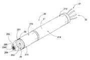
- FIG. 2is a perspective view of a skin treatment apparatus according to the above preferred embodiment of the present invention.
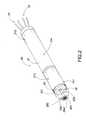
- FIG. 3is an exploded perspective view of the skin treatment apparatus according to the above preferred embodiment of the present invention.
- FIG. 4is a sectional side view of the skin treatment apparatus according to the above preferred embodiment of the present invention.
- FIG. 5is a schematic diagram of the skin treatment system according to the above preferred embodiment of the present invention.
- a skin treatment systemaccording to a preferred embodiment of the present invention is illustrated, in which the skin treatment system comprises a main unit 10 , a skin treatment apparatus 20 extended from the main unit 10 for performing skin treatment on a predetermined skin area, and an inlet arrangement 30 .
- the main unit 10comprises a main housing 11 , a vacuum source such as a pump 12 mounted in the main housing 10 , a fluid reservoir 13 mounted in the main housing 11 for containing a predetermined amount of fluid used for skin treatment purpose, a waste reservoir 14 also mounted in the main housing 11 for collecting fluid waste caused by the skin treatment, and a plurality of transmission tubes 16 connecting the fluid reservoir 13 , the skin treatment apparatus 20 , and the waste reservoir 14 in a predetermined manner for forming a skin treatment loop within the skin treatment system.
- a vacuum sourcesuch as a pump 12 mounted in the main housing 10
- a fluid reservoir 13mounted in the main housing 11 for containing a predetermined amount of fluid used for skin treatment purpose
- a waste reservoir 14also mounted in the main housing 11 for collecting fluid waste caused by the skin treatment
- a plurality of transmission tubes 16connecting the fluid reservoir 13 , the skin treatment apparatus 20 , and the waste reservoir 14 in a predetermined manner for forming a skin treatment loop within the skin treatment system.
- the skin treatment apparatus 20comprises a handle body 21 having a front end portion 211 , a rear end portion 212 , and a receiving cavity 215 formed between the front end portion 211 and the rear end portion 212 . Furthermore, the skin treatment apparatus 20 further comprises a driving unit 24 , and a treatment head unit 25 . The driving unit 24 is received in the receiving cavity 215 of the handle body 21 .
- the treatment head unit 25comprises a supporting member 251 , a treatment cap 252 , a treatment shaft 253 , and an abrasion head 254 .
- the supporting member 251is provided at the front end portion 211 of the handle body 21 , while the treatment cap 252 is detachably attached on the supporting member 251 to form a treatment cavity 255 between the supporting member 251 and the treatment cap 252 , wherein the treatment cap 252 has a through cap opening 256 formed thereon.
- the treatment shaft 253is rotatably connected to the driving unit 24 and extended from the driving unit 24 into the treatment cavity 255 .
- the abrasion head 254is integrally formed at a free end of the treatment shaft 253 in such a manner that when the treatment shaft 253 is driven to rotate, the abrasion to head 254 is also driven to rotate with respect to the handle body 21 , wherein a length of the treatment shaft 253 and the abrasion head 254 is slightly shorter than a length of the treatment cap 252 so as to form a treatment gap defined between the abrasion head 254 and the cap opening 256 .
- the an inlet arrangement 30which comprises a fluid inlet 31 and a vacuum inlet 32 formed the rear end portion 212 of the handle body 21 for providing a predetermined amount of skin treatment fluid in the treatment cavity 255 , wherein the inlet arrangement 30 is arranged to generate a vacuum effect in the treatment cavity 255 so that the skin treatment fluid is capable of being effectively and efficiently delivered to and sucked out of the treatment cavity 255 while the abrasion head 254 operates to treat user's skin.
- the skin treatment apparatusfurther comprises a securing member 26 mounted in the receiving cavity 215 of the handle body 21 for securely mounting the driving unit 24 within the receiving cavity 215 .
- the securing member 26has a tubular structure and has a through hole 261 formed thereon for allowing the treatment shaft 253 of the treatment head unit 25 to pass therethrough.
- the securing member 26is mounted in the receiving cavity 215 of the handle body 21 to define the receiving cavity 215 in a front receiving portion 2151 and a rear receiving portion 2152 , wherein the driving unit 24 is accommodated in the rear receiving portion 2152 , while the treatment shaft 253 is extended from the driving unit 24 to the first receiving portion 2151 through the securing member 26 .
- the handle body 21further comprises a front body part 213 and a rear body part 214 , wherein the front end portion 211 is formed on the front body part 213 while the rear end portion 212 is formed on the rear body part 214 respectively.
- the securing member 26has an outer circumferential ridge 262 outwardly protruded from a mid portion thereof to divide the securing member 26 into a first connecting portion 263 and a second connecting portion 264 , wherein an external surface of each of the first connecting portion 263 and the second connecting portion 264 are threaded to connect with the handle body 21 .
- the front body part 213is threadedly connected to the first connecting portion 263 of the securing member 26 while the rear body part 214 is threadedly connected to the second connecting portion 264 of the securing member 26 .
- the securing member 26is preferably made of metallic material so as to ensure sufficient material strength thereof.
- the supporting member 251has a circular cross section and is preferably made of plastic material. Moreover, the supporting member 251 further has a plurality of peripheral rims 2511 outwardly and circumferentially protruded from an outer surface of the supporting member 251 , wherein the front body part 213 of the handle body 214 is connected to the supporting member 251 at the corresponding peripheral rim 2511 .
- the peripheral rims 2511may be embodied as O-rings attached on the supporting member 251 .
- the supporting member 251further has a central through slot 2512 formed thereon, wherein the treatment shaft 253 is arranged to extend from the receiving cavity 215 to the treatment cavity 255 through the central through slot 2512 .
- the supporting member 251has a concave front surface 2513 wherein the central through slot 2512 is formed on the concave front surface 2513 .
- the provision of the concave front surface 2513serves to maximize the volume of the treatment cavity 255 and to enable a more effective and efficient vacuum effect to be formed in the treatment cavity 255 .
- the fluid inlet 31 and a vacuum inlet 32are formed at the rear end portion 212 of the handle body 21 (i.e. the rear body part 214 ), wherein the inlet arrangement 30 further has a fluid outlet 33 and a vacuum outlet 34 spacedly formed on the concave front surface 2513 of the supporting member 251 . Moreover, the inlet arrangement 30 further comprises a plurality of fluid passage tubes 35 extended between the fluid inlet 31 and the fluid outlet 33 , and between the vacuum 32 and the vacuum outlet 34 respectively.
- the main unit 10further comprises a pressure gauge 18 provided on the main housing 10 , wherein the pressure gauge 18 has a plurality of unit indicators 19 formed thereon for allowing a user to discern a current pressure and vacuum level of the skin treatment system. As such, the user is able to monitor the treatment status in a real-time manner.
- the pressure gauge 18is connected to the fluid reservoir 13 and the waste reservoir 14 for monitoring the pressure level of the skin treatment system.
- the skin treatment systemfurther comprises an adjustment switch 17 connected to the pump 12 and the pressure gauge 18 for adjusting a fluid flow in the skin treatment system.
- the fluid reservoir 13is mounted in the main housing 11 and is arranged to contain a predetermined amount of treatment fluid and optionally a predetermined amount of abrasive materials, wherein when the pump 12 is activated to create a vacuum effect in the skin treatment system, the treatment fluid is pumped to the skin treatment apparatus and reaches the skin surface through the fluid outlet 33 provided at the treatment head unit 25 .
- the skin treatment systemfurther comprises a filter unit 70 provided in-line in between the pump 12 and the waste reservoir 14 so as to ensure the vacuum source is substantially protected against dirt from collected in the waste reservoir 14 .
- the filter unit 70may be an in-line condensation filter, or other suitable filter.
- the driving motor 24comprises a motor body 241 mounted in the receiving cavity 215 of the handle body 21 , and a driving shaft 242 extended from the motor body 241 to extend in the receiving cavity 215 .
- the skin treatment apparatus 20further comprises a connecting shaft 27 connecting the driving shaft 242 to the treatment shaft 253 in such a manner that when the driving shaft 242 is driven to rotate, the connecting shaft 27 is also driven to rotate and is arranged to drive the treatment shaft 253 to rotate as well so as to allow the abrasion head 254 to perform skin treatment to the user's skin.
- the skin treatment apparatus 20further comprises a protective tube 28 having two end portions 281 , 282 which are threaded on an external surface thereof. The corresponding end portion 281 is arranged to connect to the securing member 26 .
- the skin treatment apparatus 20further comprises a plurality of ball bearings 29 provided in the protective tube 28 , wherein the connecting shaft 27 is arranged to penetrate and is protected by the protective tube 28 .
- the connecting shaft 27is arranged to penetrate through and is supported by the ball bearings 29 .
- the abrasion head 254has a circular cross section and has an abrasive surface 2541 formed thereon, wherein the abrasion surface 2541 is aligned with the through cap opening 256 so as to perform skin treatment to the user's skin when the skin is disposed at the cap opening 256 .
Landscapes
- Health & Medical Sciences (AREA)
- Life Sciences & Earth Sciences (AREA)
- Surgery (AREA)
- Heart & Thoracic Surgery (AREA)
- Engineering & Computer Science (AREA)
- Biomedical Technology (AREA)
- Nuclear Medicine, Radiotherapy & Molecular Imaging (AREA)
- Medical Informatics (AREA)
- Molecular Biology (AREA)
- Animal Behavior & Ethology (AREA)
- General Health & Medical Sciences (AREA)
- Public Health (AREA)
- Veterinary Medicine (AREA)
- Massaging Devices (AREA)
- Surgical Instruments (AREA)
Abstract
Description
Claims (16)
Priority Applications (1)
| Application Number | Priority Date | Filing Date | Title |
|---|---|---|---|
| US13/552,657US8858570B2 (en) | 2012-07-19 | 2012-07-19 | Skin treatment apparatus |
Applications Claiming Priority (1)
| Application Number | Priority Date | Filing Date | Title |
|---|---|---|---|
| US13/552,657US8858570B2 (en) | 2012-07-19 | 2012-07-19 | Skin treatment apparatus |
Publications (2)
| Publication Number | Publication Date |
|---|---|
| US20140025090A1 US20140025090A1 (en) | 2014-01-23 |
| US8858570B2true US8858570B2 (en) | 2014-10-14 |
Family
ID=49947185
Family Applications (1)
| Application Number | Title | Priority Date | Filing Date |
|---|---|---|---|
| US13/552,657Expired - Fee RelatedUS8858570B2 (en) | 2012-07-19 | 2012-07-19 | Skin treatment apparatus |
Country Status (1)
| Country | Link |
|---|---|
| US (1) | US8858570B2 (en) |
Cited By (13)
| Publication number | Priority date | Publication date | Assignee | Title |
|---|---|---|---|---|
| US11202657B2 (en) | 2013-03-15 | 2021-12-21 | Edge Systems Llc | Devices, systems and methods for treating the skin |
| US11224728B2 (en) | 2014-12-23 | 2022-01-18 | Edge Systems Llc | Devices and methods for treating the skin using a porous member |
| US11241357B2 (en) | 2015-07-08 | 2022-02-08 | Edge Systems Llc | Devices, systems and methods for promoting hair growth |
| US11446477B2 (en) | 2005-12-30 | 2022-09-20 | Hydrafacial Llc | Devices and methods for treating skin |
| US11717326B2 (en) | 2006-03-29 | 2023-08-08 | Hydrafacial Llc | Devices, systems and methods for treating the skin |
| US11744999B2 (en) | 2014-12-23 | 2023-09-05 | Hydra Facial LLC | Devices and methods for treating the skin |
| US11883621B2 (en) | 2008-01-04 | 2024-01-30 | Hydrafacial Llc | Devices and methods for skin treatment |
| USD1016615S1 (en) | 2021-09-10 | 2024-03-05 | Hydrafacial Llc | Container for a skin treatment device |
| US12005217B2 (en) | 2008-01-29 | 2024-06-11 | Hydrafacial Llc | Devices, systems and methods for skin treatment |
| USD1042807S1 (en) | 2021-10-11 | 2024-09-17 | Hydrafacial Llc | Skin treatment tip |
| USD1065551S1 (en) | 2021-09-10 | 2025-03-04 | Hydrafacial Llc | Skin treatment device |
| US12295618B2 (en) | 2020-01-06 | 2025-05-13 | Hydrafacial Llc | Skin treatment tool applicator tip |
| USD1084369S1 (en) | 2023-02-10 | 2025-07-15 | Hydrafacial Llc | Skin treatment tip |
Families Citing this family (2)
| Publication number | Priority date | Publication date | Assignee | Title |
|---|---|---|---|---|
| WO2017031397A1 (en)* | 2015-08-19 | 2017-02-23 | Powerphase Llc | System and method for de-icing a gas turbine engine |
| US20180274534A1 (en)* | 2017-03-24 | 2018-09-27 | William Fred Wiedemann, III | Pumping system |
Citations (9)
| Publication number | Priority date | Publication date | Assignee | Title |
|---|---|---|---|---|
| US20010037118A1 (en)* | 1999-12-30 | 2001-11-01 | James F. Hann | Instruments and techniques for inducing neocollagenesis in skin treatments |
| US20020040229A1 (en)* | 2000-09-24 | 2002-04-04 | Medtronic, Inc. | Liquid cooled, powered surgical handpiece |
| US6511486B2 (en)* | 2001-03-09 | 2003-01-28 | Silhouet-Tone Ltee | Dermabrasion hand tool for abrasively removing skin surface |
| US20030195542A1 (en)* | 2002-04-10 | 2003-10-16 | Lee Sang Ho | Apparatus for making tattoo |
| US20040138680A1 (en)* | 2002-11-26 | 2004-07-15 | Twitchell David J. | Microdermabrasion apparatus and system |
| US20060106363A1 (en)* | 2004-07-01 | 2006-05-18 | Aravena Ines M | Injection systems |
| US20090222024A1 (en)* | 2006-04-07 | 2009-09-03 | Moreno Naldoni | Dermabrasion handpiece |
| USRE42960E1 (en)* | 1999-11-12 | 2011-11-22 | Altair Instruments, Inc. | Microdermabrasion device |
| US8343116B2 (en)* | 2008-01-04 | 2013-01-01 | Edge Systems Corporation | Apparatus and method for treating the skin |
- 2012
- 2012-07-19USUS13/552,657patent/US8858570B2/ennot_activeExpired - Fee Related
Patent Citations (9)
| Publication number | Priority date | Publication date | Assignee | Title |
|---|---|---|---|---|
| USRE42960E1 (en)* | 1999-11-12 | 2011-11-22 | Altair Instruments, Inc. | Microdermabrasion device |
| US20010037118A1 (en)* | 1999-12-30 | 2001-11-01 | James F. Hann | Instruments and techniques for inducing neocollagenesis in skin treatments |
| US20020040229A1 (en)* | 2000-09-24 | 2002-04-04 | Medtronic, Inc. | Liquid cooled, powered surgical handpiece |
| US6511486B2 (en)* | 2001-03-09 | 2003-01-28 | Silhouet-Tone Ltee | Dermabrasion hand tool for abrasively removing skin surface |
| US20030195542A1 (en)* | 2002-04-10 | 2003-10-16 | Lee Sang Ho | Apparatus for making tattoo |
| US20040138680A1 (en)* | 2002-11-26 | 2004-07-15 | Twitchell David J. | Microdermabrasion apparatus and system |
| US20060106363A1 (en)* | 2004-07-01 | 2006-05-18 | Aravena Ines M | Injection systems |
| US20090222024A1 (en)* | 2006-04-07 | 2009-09-03 | Moreno Naldoni | Dermabrasion handpiece |
| US8343116B2 (en)* | 2008-01-04 | 2013-01-01 | Edge Systems Corporation | Apparatus and method for treating the skin |
Cited By (24)
| Publication number | Priority date | Publication date | Assignee | Title |
|---|---|---|---|---|
| US11547840B2 (en) | 2005-12-30 | 2023-01-10 | Hydrafacial Llc | Devices and methods for treating skin |
| US12053607B2 (en) | 2005-12-30 | 2024-08-06 | Hydrafacial Llc | Devices and methods for treating skin |
| US11865287B2 (en) | 2005-12-30 | 2024-01-09 | Hydrafacial Llc | Devices and methods for treating skin |
| US11446477B2 (en) | 2005-12-30 | 2022-09-20 | Hydrafacial Llc | Devices and methods for treating skin |
| US11612726B2 (en) | 2005-12-30 | 2023-03-28 | Hydrafacial Llc | Devices and methods for treating skin |
| US11717326B2 (en) | 2006-03-29 | 2023-08-08 | Hydrafacial Llc | Devices, systems and methods for treating the skin |
| US11883621B2 (en) | 2008-01-04 | 2024-01-30 | Hydrafacial Llc | Devices and methods for skin treatment |
| US12005217B2 (en) | 2008-01-29 | 2024-06-11 | Hydrafacial Llc | Devices, systems and methods for skin treatment |
| US12186513B2 (en) | 2008-01-29 | 2025-01-07 | Hydrafacial Llc | Devices, systems and methods for skin treatment |
| US12161830B2 (en) | 2008-01-29 | 2024-12-10 | Hydrafacial Llc | Devices, systems, and methods for treating the skin |
| US11213321B2 (en) | 2013-03-15 | 2022-01-04 | Edge Systems Llc | Devices, systems and methods for treating the skin |
| US11517350B2 (en) | 2013-03-15 | 2022-12-06 | Hydrafacial Llc | Devices, systems and methods for treating the skin |
| US11202657B2 (en) | 2013-03-15 | 2021-12-21 | Edge Systems Llc | Devices, systems and methods for treating the skin |
| US11903615B2 (en) | 2013-03-15 | 2024-02-20 | Hydrafacial Llc | Devices, systems and methods for treating the skin |
| US11224728B2 (en) | 2014-12-23 | 2022-01-18 | Edge Systems Llc | Devices and methods for treating the skin using a porous member |
| US11925780B2 (en) | 2014-12-23 | 2024-03-12 | Hydrafacial Llc | Devices and methods for treating the skin |
| US11806495B2 (en) | 2014-12-23 | 2023-11-07 | Hydrafacial Llc | Devices and methods for treating the skin |
| US11744999B2 (en) | 2014-12-23 | 2023-09-05 | Hydra Facial LLC | Devices and methods for treating the skin |
| US11241357B2 (en) | 2015-07-08 | 2022-02-08 | Edge Systems Llc | Devices, systems and methods for promoting hair growth |
| US12295618B2 (en) | 2020-01-06 | 2025-05-13 | Hydrafacial Llc | Skin treatment tool applicator tip |
| USD1016615S1 (en) | 2021-09-10 | 2024-03-05 | Hydrafacial Llc | Container for a skin treatment device |
| USD1065551S1 (en) | 2021-09-10 | 2025-03-04 | Hydrafacial Llc | Skin treatment device |
| USD1042807S1 (en) | 2021-10-11 | 2024-09-17 | Hydrafacial Llc | Skin treatment tip |
| USD1084369S1 (en) | 2023-02-10 | 2025-07-15 | Hydrafacial Llc | Skin treatment tip |
Also Published As
| Publication number | Publication date |
|---|---|
| US20140025090A1 (en) | 2014-01-23 |
Similar Documents
| Publication | Publication Date | Title |
|---|---|---|
| US8858570B2 (en) | Skin treatment apparatus | |
| US10792417B2 (en) | Removable transmission for use with a powered surgical tool, the transmission shaped to extend above the tool, and system | |
| US9546662B2 (en) | Medical pump | |
| US6517511B2 (en) | Cleansable multi-purpose nasal discharge aspirator | |
| US10201334B2 (en) | Coupling device between the drive shaft of a surgical instrument and a tool | |
| EP2496277A1 (en) | Actuated self unplugging surgical sucker wand | |
| EP1372755A2 (en) | An apparatus for flushing peripheral organs in humans or animals | |
| CN211213277U (en) | Control device of handheld surgical equipment and handheld surgical equipment | |
| EP3103382B1 (en) | Mouth mirror apparatus | |
| CN211213353U (en) | Hand-held surgical device | |
| US8176989B1 (en) | Wheeled support for using a trimmer as a hand-held lawn edger | |
| CN205597978U (en) | Ultrasonic knife sleeve pipe aspirator and ultrasonic knife | |
| KR20200106687A (en) | Bush cutting machine | |
| CN101657163A (en) | Wound bed preparation | |
| US6634050B1 (en) | Cleaning apparatus | |
| CN112847449A (en) | Nose hair pruning equipment before rhinitis operation for department of ophthalmology and otorhinolaryngology in hospital | |
| CN112315542A (en) | Hand-held surgical device | |
| CN108781723A (en) | A kind of full-automatic weeder | |
| CN114081575B (en) | Disposable electric bone rasp | |
| CN217040225U (en) | Disposable electric bone file | |
| US12102783B1 (en) | Electric flusher | |
| JP3192091U (en) | Tank water supply grinder | |
| CN215127872U (en) | Portable bathing machine of suction formula | |
| JPH04361743A (en) | Ultrasonic operation device | |
| CN115068044A (en) | Medical electric swing saw for orthopedics department |
Legal Events
| Date | Code | Title | Description |
|---|---|---|---|
| AS | Assignment | Owner name:CHANG, HENRY PING, CALIFORNIA Free format text:ASSIGNMENT OF ASSIGNORS INTEREST;ASSIGNOR:CHANG, HENRY PING;REEL/FRAME:029939/0962 Effective date:20130306 Owner name:CHANG, FRANKLIN, CALIFORNIA Free format text:ASSIGNMENT OF ASSIGNORS INTEREST;ASSIGNOR:CHANG, HENRY PING;REEL/FRAME:029939/0962 Effective date:20130306 | |
| AS | Assignment | Owner name:CHANG, HENRY PING, CALIFORNIA Free format text:ASSIGNMENT OF ASSIGNORS INTEREST;ASSIGNORS:CHANG, HENRY PING;CHANG, FRANKLIN;REEL/FRAME:033691/0010 Effective date:20140820 Owner name:CHANG, TSUNG CHANG, TAIWAN Free format text:ASSIGNMENT OF ASSIGNORS INTEREST;ASSIGNORS:CHANG, HENRY PING;CHANG, FRANKLIN;REEL/FRAME:033691/0010 Effective date:20140820 Owner name:CHANG, FRANKLIN, CALIFORNIA Free format text:ASSIGNMENT OF ASSIGNORS INTEREST;ASSIGNORS:CHANG, HENRY PING;CHANG, FRANKLIN;REEL/FRAME:033691/0010 Effective date:20140820 | |
| STCF | Information on status: patent grant | Free format text:PATENTED CASE | |
| MAFP | Maintenance fee payment | Free format text:PAYMENT OF MAINTENANCE FEE, 4TH YR, SMALL ENTITY (ORIGINAL EVENT CODE: M2551) Year of fee payment:4 | |
| FEPP | Fee payment procedure | Free format text:MAINTENANCE FEE REMINDER MAILED (ORIGINAL EVENT CODE: REM.); ENTITY STATUS OF PATENT OWNER: SMALL ENTITY | |
| LAPS | Lapse for failure to pay maintenance fees | Free format text:PATENT EXPIRED FOR FAILURE TO PAY MAINTENANCE FEES (ORIGINAL EVENT CODE: EXP.); ENTITY STATUS OF PATENT OWNER: SMALL ENTITY | |
| STCH | Information on status: patent discontinuation | Free format text:PATENT EXPIRED DUE TO NONPAYMENT OF MAINTENANCE FEES UNDER 37 CFR 1.362 | |
| FP | Lapsed due to failure to pay maintenance fee | Effective date:20221014 |