US8858511B2 - Fluid delivery and measurement systems and methods - Google Patents
Fluid delivery and measurement systems and methodsDownload PDFInfo
- Publication number
- US8858511B2 US8858511B2US12/336,246US33624608AUS8858511B2US 8858511 B2US8858511 B2US 8858511B2US 33624608 AUS33624608 AUS 33624608AUS 8858511 B2US8858511 B2US 8858511B2
- Authority
- US
- United States
- Prior art keywords
- housing
- needle
- fluid
- fluid delivery
- delivery device
- Prior art date
- Legal status (The legal status is an assumption and is not a legal conclusion. Google has not performed a legal analysis and makes no representation as to the accuracy of the status listed.)
- Expired - Lifetime, expires
Links
Images


Classifications
- A—HUMAN NECESSITIES
- A61—MEDICAL OR VETERINARY SCIENCE; HYGIENE
- A61M—DEVICES FOR INTRODUCING MEDIA INTO, OR ONTO, THE BODY; DEVICES FOR TRANSDUCING BODY MEDIA OR FOR TAKING MEDIA FROM THE BODY; DEVICES FOR PRODUCING OR ENDING SLEEP OR STUPOR
- A61M5/00—Devices for bringing media into the body in a subcutaneous, intra-vascular or intramuscular way; Accessories therefor, e.g. filling or cleaning devices, arm-rests
- A61M5/14—Infusion devices, e.g. infusing by gravity; Blood infusion; Accessories therefor
- A61M5/142—Pressure infusion, e.g. using pumps
- A61M5/145—Pressure infusion, e.g. using pumps using pressurised reservoirs, e.g. pressurised by means of pistons
- A61M5/155—Pressure infusion, e.g. using pumps using pressurised reservoirs, e.g. pressurised by means of pistons pressurised by gas introduced into the reservoir
- A—HUMAN NECESSITIES
- A61—MEDICAL OR VETERINARY SCIENCE; HYGIENE
- A61M—DEVICES FOR INTRODUCING MEDIA INTO, OR ONTO, THE BODY; DEVICES FOR TRANSDUCING BODY MEDIA OR FOR TAKING MEDIA FROM THE BODY; DEVICES FOR PRODUCING OR ENDING SLEEP OR STUPOR
- A61M5/00—Devices for bringing media into the body in a subcutaneous, intra-vascular or intramuscular way; Accessories therefor, e.g. filling or cleaning devices, arm-rests
- A61M5/14—Infusion devices, e.g. infusing by gravity; Blood infusion; Accessories therefor
- A61M5/142—Pressure infusion, e.g. using pumps
- A61M5/14244—Pressure infusion, e.g. using pumps adapted to be carried by the patient, e.g. portable on the body
- A61M5/14248—Pressure infusion, e.g. using pumps adapted to be carried by the patient, e.g. portable on the body of the skin patch type
- A—HUMAN NECESSITIES
- A61—MEDICAL OR VETERINARY SCIENCE; HYGIENE
- A61M—DEVICES FOR INTRODUCING MEDIA INTO, OR ONTO, THE BODY; DEVICES FOR TRANSDUCING BODY MEDIA OR FOR TAKING MEDIA FROM THE BODY; DEVICES FOR PRODUCING OR ENDING SLEEP OR STUPOR
- A61M5/00—Devices for bringing media into the body in a subcutaneous, intra-vascular or intramuscular way; Accessories therefor, e.g. filling or cleaning devices, arm-rests
- A61M5/14—Infusion devices, e.g. infusing by gravity; Blood infusion; Accessories therefor
- A61M5/142—Pressure infusion, e.g. using pumps
- A61M5/145—Pressure infusion, e.g. using pumps using pressurised reservoirs, e.g. pressurised by means of pistons
- A61M5/1452—Pressure infusion, e.g. using pumps using pressurised reservoirs, e.g. pressurised by means of pistons pressurised by means of pistons
- A61M5/14526—Pressure infusion, e.g. using pumps using pressurised reservoirs, e.g. pressurised by means of pistons pressurised by means of pistons the piston being actuated by fluid pressure
- A—HUMAN NECESSITIES
- A61—MEDICAL OR VETERINARY SCIENCE; HYGIENE
- A61M—DEVICES FOR INTRODUCING MEDIA INTO, OR ONTO, THE BODY; DEVICES FOR TRANSDUCING BODY MEDIA OR FOR TAKING MEDIA FROM THE BODY; DEVICES FOR PRODUCING OR ENDING SLEEP OR STUPOR
- A61M5/00—Devices for bringing media into the body in a subcutaneous, intra-vascular or intramuscular way; Accessories therefor, e.g. filling or cleaning devices, arm-rests
- A61M5/14—Infusion devices, e.g. infusing by gravity; Blood infusion; Accessories therefor
- A61M5/142—Pressure infusion, e.g. using pumps
- A61M5/145—Pressure infusion, e.g. using pumps using pressurised reservoirs, e.g. pressurised by means of pistons
- A61M5/14586—Pressure infusion, e.g. using pumps using pressurised reservoirs, e.g. pressurised by means of pistons pressurised by means of a flexible diaphragm
- A61M5/14593—Pressure infusion, e.g. using pumps using pressurised reservoirs, e.g. pressurised by means of pistons pressurised by means of a flexible diaphragm the diaphragm being actuated by fluid pressure
- A—HUMAN NECESSITIES
- A61—MEDICAL OR VETERINARY SCIENCE; HYGIENE
- A61M—DEVICES FOR INTRODUCING MEDIA INTO, OR ONTO, THE BODY; DEVICES FOR TRANSDUCING BODY MEDIA OR FOR TAKING MEDIA FROM THE BODY; DEVICES FOR PRODUCING OR ENDING SLEEP OR STUPOR
- A61M5/00—Devices for bringing media into the body in a subcutaneous, intra-vascular or intramuscular way; Accessories therefor, e.g. filling or cleaning devices, arm-rests
- A61M5/14—Infusion devices, e.g. infusing by gravity; Blood infusion; Accessories therefor
- A61M5/158—Needles for infusions; Accessories therefor, e.g. for inserting infusion needles, or for holding them on the body
- A—HUMAN NECESSITIES
- A61—MEDICAL OR VETERINARY SCIENCE; HYGIENE
- A61M—DEVICES FOR INTRODUCING MEDIA INTO, OR ONTO, THE BODY; DEVICES FOR TRANSDUCING BODY MEDIA OR FOR TAKING MEDIA FROM THE BODY; DEVICES FOR PRODUCING OR ENDING SLEEP OR STUPOR
- A61M5/00—Devices for bringing media into the body in a subcutaneous, intra-vascular or intramuscular way; Accessories therefor, e.g. filling or cleaning devices, arm-rests
- A61M5/14—Infusion devices, e.g. infusing by gravity; Blood infusion; Accessories therefor
- A61M5/168—Means for controlling media flow to the body or for metering media to the body, e.g. drip meters, counters ; Monitoring media flow to the body
- A61M5/16804—Flow controllers
- A—HUMAN NECESSITIES
- A61—MEDICAL OR VETERINARY SCIENCE; HYGIENE
- A61M—DEVICES FOR INTRODUCING MEDIA INTO, OR ONTO, THE BODY; DEVICES FOR TRANSDUCING BODY MEDIA OR FOR TAKING MEDIA FROM THE BODY; DEVICES FOR PRODUCING OR ENDING SLEEP OR STUPOR
- A61M5/00—Devices for bringing media into the body in a subcutaneous, intra-vascular or intramuscular way; Accessories therefor, e.g. filling or cleaning devices, arm-rests
- A61M5/14—Infusion devices, e.g. infusing by gravity; Blood infusion; Accessories therefor
- A61M5/168—Means for controlling media flow to the body or for metering media to the body, e.g. drip meters, counters ; Monitoring media flow to the body
- A61M5/16831—Monitoring, detecting, signalling or eliminating infusion flow anomalies
- A—HUMAN NECESSITIES
- A61—MEDICAL OR VETERINARY SCIENCE; HYGIENE
- A61M—DEVICES FOR INTRODUCING MEDIA INTO, OR ONTO, THE BODY; DEVICES FOR TRANSDUCING BODY MEDIA OR FOR TAKING MEDIA FROM THE BODY; DEVICES FOR PRODUCING OR ENDING SLEEP OR STUPOR
- A61M5/00—Devices for bringing media into the body in a subcutaneous, intra-vascular or intramuscular way; Accessories therefor, e.g. filling or cleaning devices, arm-rests
- A61M5/14—Infusion devices, e.g. infusing by gravity; Blood infusion; Accessories therefor
- A61M5/142—Pressure infusion, e.g. using pumps
- A61M2005/14204—Pressure infusion, e.g. using pumps with gas-producing electrochemical cell
- A—HUMAN NECESSITIES
- A61—MEDICAL OR VETERINARY SCIENCE; HYGIENE
- A61M—DEVICES FOR INTRODUCING MEDIA INTO, OR ONTO, THE BODY; DEVICES FOR TRANSDUCING BODY MEDIA OR FOR TAKING MEDIA FROM THE BODY; DEVICES FOR PRODUCING OR ENDING SLEEP OR STUPOR
- A61M5/00—Devices for bringing media into the body in a subcutaneous, intra-vascular or intramuscular way; Accessories therefor, e.g. filling or cleaning devices, arm-rests
- A61M5/14—Infusion devices, e.g. infusing by gravity; Blood infusion; Accessories therefor
- A61M5/142—Pressure infusion, e.g. using pumps
- A61M5/14244—Pressure infusion, e.g. using pumps adapted to be carried by the patient, e.g. portable on the body
- A61M5/14248—Pressure infusion, e.g. using pumps adapted to be carried by the patient, e.g. portable on the body of the skin patch type
- A61M2005/14252—Pressure infusion, e.g. using pumps adapted to be carried by the patient, e.g. portable on the body of the skin patch type with needle insertion means
- A—HUMAN NECESSITIES
- A61—MEDICAL OR VETERINARY SCIENCE; HYGIENE
- A61M—DEVICES FOR INTRODUCING MEDIA INTO, OR ONTO, THE BODY; DEVICES FOR TRANSDUCING BODY MEDIA OR FOR TAKING MEDIA FROM THE BODY; DEVICES FOR PRODUCING OR ENDING SLEEP OR STUPOR
- A61M5/00—Devices for bringing media into the body in a subcutaneous, intra-vascular or intramuscular way; Accessories therefor, e.g. filling or cleaning devices, arm-rests
- A61M5/14—Infusion devices, e.g. infusing by gravity; Blood infusion; Accessories therefor
- A61M5/142—Pressure infusion, e.g. using pumps
- A61M5/14244—Pressure infusion, e.g. using pumps adapted to be carried by the patient, e.g. portable on the body
- A61M2005/14264—Pressure infusion, e.g. using pumps adapted to be carried by the patient, e.g. portable on the body with means for compensating influence from the environment
- A—HUMAN NECESSITIES
- A61—MEDICAL OR VETERINARY SCIENCE; HYGIENE
- A61M—DEVICES FOR INTRODUCING MEDIA INTO, OR ONTO, THE BODY; DEVICES FOR TRANSDUCING BODY MEDIA OR FOR TAKING MEDIA FROM THE BODY; DEVICES FOR PRODUCING OR ENDING SLEEP OR STUPOR
- A61M2205/00—General characteristics of the apparatus
- A61M2205/27—General characteristics of the apparatus preventing use
- A61M2205/276—General characteristics of the apparatus preventing use preventing unwanted use
- A—HUMAN NECESSITIES
- A61—MEDICAL OR VETERINARY SCIENCE; HYGIENE
- A61M—DEVICES FOR INTRODUCING MEDIA INTO, OR ONTO, THE BODY; DEVICES FOR TRANSDUCING BODY MEDIA OR FOR TAKING MEDIA FROM THE BODY; DEVICES FOR PRODUCING OR ENDING SLEEP OR STUPOR
- A61M2205/00—General characteristics of the apparatus
- A61M2205/82—Internal energy supply devices
- A61M2205/8206—Internal energy supply devices battery-operated
- A—HUMAN NECESSITIES
- A61—MEDICAL OR VETERINARY SCIENCE; HYGIENE
- A61M—DEVICES FOR INTRODUCING MEDIA INTO, OR ONTO, THE BODY; DEVICES FOR TRANSDUCING BODY MEDIA OR FOR TAKING MEDIA FROM THE BODY; DEVICES FOR PRODUCING OR ENDING SLEEP OR STUPOR
- A61M2205/00—General characteristics of the apparatus
- A61M2205/82—Internal energy supply devices
- A61M2205/8218—Gas operated
- A61M2205/8231—Gas operated using electrochemical gas generating device for the driving gas
- A—HUMAN NECESSITIES
- A61—MEDICAL OR VETERINARY SCIENCE; HYGIENE
- A61M—DEVICES FOR INTRODUCING MEDIA INTO, OR ONTO, THE BODY; DEVICES FOR TRANSDUCING BODY MEDIA OR FOR TAKING MEDIA FROM THE BODY; DEVICES FOR PRODUCING OR ENDING SLEEP OR STUPOR
- A61M5/00—Devices for bringing media into the body in a subcutaneous, intra-vascular or intramuscular way; Accessories therefor, e.g. filling or cleaning devices, arm-rests
- A61M5/14—Infusion devices, e.g. infusing by gravity; Blood infusion; Accessories therefor
- A61M5/142—Pressure infusion, e.g. using pumps
- A61M5/145—Pressure infusion, e.g. using pumps using pressurised reservoirs, e.g. pressurised by means of pistons
- A61M5/148—Pressure infusion, e.g. using pumps using pressurised reservoirs, e.g. pressurised by means of pistons flexible, e.g. independent bags
- A61M5/1483—Pressure infusion, e.g. using pumps using pressurised reservoirs, e.g. pressurised by means of pistons flexible, e.g. independent bags using flexible bags externally pressurised by fluid pressure
Definitions
- the inventionrelates to fluid delivery and measurement systems and methods.
- Fluid delivery systemscan be used to deliver a fluid, such as a pharmacological compound (e.g., a therapeutic agent), from a reservoir to a subject, such as a human.
- a fluid delivery systemincludes a housing containing a deformable membrane and a fluid reservoir.
- the needleis in fluid communication with the fluid reservoir so that as a force is exerted against the deformable membrane, the fluid can exit the system via the needle.
- the needleis inserted into a subject (e.g., a human) so that the fluid is injected into the subject as the fluid leaves the system.
- the inventionrelates to fluid delivery and measurement systems and methods.
- the inventionfeatures a device that includes a housing and a flexible member within the interior of the housing and mechanically coupled to the housing.
- the flexible memberforms first and second chambers within the interior of the housing.
- the devicefurther includes a fluid reservoir within the first chamber of the housing and a microprobe extending from the fluid reservoir, through the flexible member and into the second chamber of the housing.
- the microprobeis configured to move substantially freely in three mutually perpendicular directions. In certain embodiments, the microprobe is configured to translate in a first direction and rotate substantially freely in plane perpendicular to the first direction.
- the inventionfeatures a device that includes a housing and a flexible member within the interior of the housing and mechanically coupled to the housing.
- the flexible memberforms first and second chambers within the interior of the housing.
- the devicealso includes a fluid reservoir within the first chamber of the housing, and a flexible tube having a first end and a second end. The first end of the flexible tube is connected to the flexible member and in fluid communication with the fluid reservoir via the flexible member.
- the devicealso includes a microprobe connected to the second end of the flexible tube.
- the microprobecan be configured to move substantially freely in three mutually perpendicular directions.
- the microprobecan be configured to translate in a first direction and rotate substantially freely in plane perpendicular to the first direction.
- Embodimentscan have one or more of the following features.
- the first end of the microprobecan be in the fluid reservoir, and the second end of the microprobe can be capable of extending to the exterior of the housing.
- the microprobecan be mechanically coupled to the flexible member.
- the microprobecan be a needle or a microneedle.
- the flexible membercan be a septum.
- the devicecan further include a pump in fluid communication with the fluid reservoir.
- the pumpcan be configured to draw a fluid from the microprobe into the fluid reservoir.
- the pumpcan be configured to deliver a fluid from the fluid reservoir to the microprobe.
- the pumpcan be a gas generating source.
- the pumpcan be an electrochemical cell.
- the devicecan be a device for delivering a fluid from the fluid reservoir to the exterior of the device via the microprobe.
- the devicecan be a device for delivering a fluid to the fluid reservoir from the exterior of the device via the microprobe.
- the microprobecan be capable of moving a distance in a first direction that is at least about two percent (e.g., at least about five percent, at least about 10 percent, at least about 20 percent, at least about 30 percent, at least about 40 percent, at least about 50 percent, at least about 60 percent, at least about 70 percent, at least about 80 percent, at least about 90 percent) of a distance the microprobe is capable of moving in a second direction perpendicular to the first direction.
- a distance in a first directionthat is at least about two percent (e.g., at least about five percent, at least about 10 percent, at least about 20 percent, at least about 30 percent, at least about 40 percent, at least about 50 percent, at least about 60 percent, at least about 70 percent, at least about 80 percent, at least about 90 percent) of a distance the microprobe is capable of moving in a second direction perpendicular to the first direction.
- the microprobecan be capable of moving a distance in a third direction that is at least about two percent (e.g., at least about five percent, at least about 10 percent, at least about 20 percent, at least about 30 percent, at least about 40 percent, at least about 50 percent, at least about 60 percent, at least about 70 percent, at least about 80 percent, at least about 90 percent) of the distance the microprobe is capable of moving in the second direction, the third direction being perpendicular to the first and second directions.
- the third directionbeing perpendicular to the first and second directions.
- the inventionfeatures a fluid delivery device that includes a first housing and a flexible member within the interior of the first housing and mechanically coupled to the first housing.
- the flexible memberforms first and second chambers within the interior of the first housing.
- the devicealso includes a gas generator in fluid communication with the flexible member via the first chamber of the first housing and a microprobe connected to the first housing so that when the gas generator produces a gas pressure sufficient to move the move the flexible member a portion of a fluid disposed in the second chamber is ejected via the microprobe.
- the deviceadditionally includes a second housing in fluid communication with the first chamber of the first housing so that the second housing is capable of increasing the pressure in the first chamber of the first housing to increase a rate of fluid ejection via the microprobe.
- the inventionfeatures a fluid delivery device that includes a housing and a flexible member within the interior of the housing and mechanically coupled to the housing.
- the flexible memberforms first and second chambers within the housing.
- the devicealso includes a microprobe connected to the housing and in fluid communication with the first chamber of the housing and a gas generator in fluid communication with the second chamber of the housing.
- the gas generatoris capable of increasing the pressure in the second chamber to move the flexible member thereby ejecting a fluid disposed in the first chamber out of the housing via the microprobe.
- the devicefurther includes a current generator in electrical communication with the gas generator. The current generator is configured so that when a current output by the current generator is varied, the gas output by the gas generator is correspondingly varied and the rate of fluid ejected by the microprobe is also correspondingly varied.
- the inventionfeatures a fluid delivery device that includes a housing and a flexible member disposed in the interior of the housing and mechanically coupled to the housing.
- the flexible memberforms first and second chambers within the housing.
- a microprobeis connected to the housing and in fluid communication with the first chamber of the housing.
- the devicealso includes a gas generator in fluid communication with the second chamber of the housing. The gas generator is capable of increasing the pressure in the second chamber to move the flexible member thereby ejecting a fluid disposed in the first chamber out of the housing via the microprobe.
- the devicefurther includes at least one pressure relief valve in fluid communication with the second chamber of the housing. The pressure relief valve(s) is(are) able to compensate for a difference between a pressure of the interior of the housing and a pressure of the exterior of the housing.
- the inventionfeatures a fluid delivery device that includes a housing and a flexible member disposed in the interior of the housing and mechanically coupled to the housing.
- the flexible memberforms first and second chambers within the housing.
- a microprobeconnected to the housing and in fluid communication with the first chamber of the housing, and a gas generator is in fluid communication with the second chamber of the housing.
- the gas generatoris capable of increasing the pressure in the second chamber to move the flexible member thereby ejecting a fluid disposed in the first chamber out of the housing via the microprobe.
- the devicealso includes a second housing, a diluent reservoir in the second housing, a piston in fluid communication with the diluent reservoir and a powder chamber in fluid communication with the diluent reservoir and the first chamber of the first housing.
- the pistonis configured so that it is capable of applying a pressure to urge a fluid from the diluent reservoir to the powder chamber, thereby mixing the fluid with a powder contained in the powder reservoir to form a mixture and to urge the mixture into the first chamber of the first housing.
- the inventionfeatures a sensor system that includes a microprobe, a sensor and a pump.
- the pumpis configured to apply a suction to the microprobe so that the microprobe can withdraw a fluid from a body and pass the fluid to the sensor for detection.
- the sensor systemcan further include a flow restriction device between the microprobe and the sensor along a fluid flow path from the microprobe to the sensor and a re-fill device in fluid communication between the pump and the sensor along a fluid flow path from the pump to the sensor.
- the inventionfeatures a fluid delivery device that includes a housing a piston in the interior of the housing, and a gas source in fluid communication with the interior of the housing.
- the gas sourceis configured to exert a pressure against the piston in a first direction.
- the devicealso includes a resilient device configured to exert a pressure against the piston in a second direction opposite the first direction, an arm, an actuation device and a valve having an open position and a closed position.
- the inventionfeatures a device that includes a fluid reservoir capable of containing a fluid and a first drive mechanism configured to remove a predetermined amount of the fluid from the fluid reservoir when the first drive mechanism is actuated.
- the deviceis configured to prevent the first drive mechanism from being re-actuated until the predetermined amount of the fluid is removed.
- the devicecan further include a second drive mechanism configured to remove fluid from the fluid reservoir at a first predetermined rate.
- the first drive mechanismcan enable fluid to be removed from the fluid reservoir at a second predetermined rate different than the first predetermined rate.
- the second predetermined ratecan be higher than the first predetermined rate.
- the second drive mechanismcan be a gas generating source.
- the gas generating sourcecan be in fluid communication with a movable member.
- the first drive mechanismcan be a compressive force.
- the first drive mechanismcan be a spring.
- the fluid delivery systemscan be designed to provide improved flexibility and/or patient comfort.
- the deviceis designed so that a rigid microprobe (e.g., a microneedle or a rigid needle) can be inserted into a subject (e.g., a human) while the device maintains several degrees of freedom so that the subject can move while feeling reduced pain because the system responds to the subject's movement.
- a rigid microprobee.g., a microneedle or a rigid needle
- the inventionfeatures a device that includes a fluid reservoir, a septum, a rigid microprobe (e.g., a needle or a microneedle), and a housing having an orifice.
- a fluid reservoire.g., a blood vessel
- a septume.g., a septum
- a rigid microprobee.g., a needle or a microneedle
- a housinghaving an orifice.
- Embodimentsmay include one or more of the following features.
- the devicecan have several degrees of freedom of movement.
- the devicecan move relative to a subject.
- the septumcan move, or it can be stationary.
- the devicecan include flexible tubing mechanically coupled to the rigid microprobe.
- the devicecan be a component of an electrochemical cell system.
- the systems and methodscan deliver a fluid to a subject with greater subject comfort, e.g., with a rigid member, and high reliability.
- the inventionfeatures systems and methods that include delivering a fluid from a reservoir to a patient at a first rate, then delivering the fluid from the reservoir to the patient at a second rate different than the first rate.
- the systems and methodscan provide both fluid (e.g., a pharmacological compound, such as a therapeutic agent, such as insulin) delivery to a patient (e.g., a human) at a relatively constant period of time and fluid delivery at an increased rate for a desired period of time. In certain embodiments, this can correspond to a basal delivery rate and a bolus delivery rate, respectively.
- fluide.g., a pharmacological compound, such as a therapeutic agent, such as insulin
- a patiente.g., a human
- thiscan correspond to a basal delivery rate and a bolus delivery rate, respectively.
- the inventionprovides a device that includes a delivery device, an auxiliary gas source and a conduit that provides fluid communication between the delivery device and the auxiliary gas source.
- the delivery devicecan include a gas source, a deformable layer, a fluid reservoir and a needle or microneedle in fluid communication with the fluid reservoir.
- the components of the delivery devicecan be arranged so that as the gas source creates a gas within the delivery device the created gas exerts a pressure against the deformable layer causing the deformable layer to exert a pressure against the fluid reservoir, causing the fluid in the fluid reservoir to exit the delivery device via the needle or the microneedle.
- the fluidcan be a pharmacological compound (e.g., a therapeutic agent, such as insulin).
- the gas source in the delivery devicecan be an electrochemical cell (e.g., a fuel cell).
- the auxiliary gas sourcecan house a gas mixture at a pressure higher than the pressure of the gas in the delivery device.
- the auxiliary gas sourcecan include a gas source.
- the gas source in the auxiliary gas sourcecan be an electrochemical cell (e.g., a fuel cell).
- the inventionfeatures a device that can deliver a fluid, such as a therapeutic agent, variably, for example, by varying the current output from a current source.
- the inventionfeatures a device having a first chamber, a second chamber, and a deformable membrane between the first and second chambers.
- the second chamberincludes a variable and controllable current source electrically connected to a gas generator.
- the inventionfeatures systems and methods that compensate for a gas pressure differential between an interior and exterior gas pressure to a fluid delivery device.
- Compensationcan be achieved using one or more valves.
- compensationcan be achieved by having one or more valves open or close as a result of the gas pressure differential.
- the systems and methodscan reduce overdelivery and/or underdelivery of fluid to a subject (e.g., a human) when the gas pressure differential between the interior and exterior of the delivery device meets or exceeds some predetermined level.
- a subjecte.g., a human
- the systems and methodscan reduce overdelivery or underdelivery of fluid to a subject (e.g., a human) when the gas pressure external to the delivery device undergoes a relatively rapid decrease or increase, respectively (e.g., when ascending or descending, respectively, in an airplane).
- a subjecte.g., a human
- the gas pressure external to the delivery deviceundergoes a relatively rapid decrease or increase, respectively (e.g., when ascending or descending, respectively, in an airplane).
- the inventionfeatures a device that includes a housing, a gas source, a deformable layer, a fluid reservoir, a valve, and a transmission device.
- the valvecan be designed to provide fluid communication between the interior and exterior of the housing when the valve is in a first position, and/or to prevent fluid communication between the interior and exterior of the housing when the valve is in a different position.
- the devicecan include more than one valve.
- the gas sourcecan create a gas that exerts a force against the deformable layer to cause a fluid contained in the fluid reservoir to exit the device via the transmission device.
- the gas sourcecan be an electrochemical cell, such as, for example, a fuel cell.
- the transmission devicecan be a needle or a microneedle.
- the inventionfeatures a device that includes a housing, a gas source, a piston, a spring, a valve, and an actuation arm.
- Embodimentsinclude one or more of the following features.
- the components of the devicecan be assembled so that the gas source can form a gas that exerts a pressure against the piston to move the piston in a direction away from the gas source.
- the piston and actuation armcan be mechanically coupled.
- the springcan be disposed within the housing so that it exerts a force in a direction opposite to the direction of the force created when the gas source forms a gas.
- the actuation armcan be coupled to a pumping mechanism.
- the actuation armcan be coupled to a deformable membrane so that the actuation arm can exert a force against the deformable membrane.
- the deformable membranecan be coupled to a fluid reservoir so that the deformable membrane can exert a force against a fluid contained in the fluid reservoir.
- the fluid reservoircan be in fluid communication with a needle or a microneedle.
- the actuation armcan exert a force against the deformable membrane, which can exert a force against a fluid in the fluid reservoir, and the fluid can exit the device via the needle or the microneedle.
- the inventionfeatures a device that includes two housings, the first housing can be used to mix a diluent and a powder to form a mixture, and the second housing can be used to transfer the mixture to a subject.
- the first housingcan include a diluent chamber and a powder chamber.
- the diluent and powder chamberscan be in fluid communication.
- the first and second housingscan be in fluid communication via a seal, which prevents fluid communication between the first and second housings until the seal is opened or broken.
- the second housingcan include a reservoir in fluid communication with the powder chamber via the seal.
- the second housingcan further include a gas source and a deformable layer.
- the second housingcan further include a transmission device so that fluid can exit the fluid reservoir via the transmission device.
- the inventionfeatures a method that includes transferring diluent from a diluent chamber in a first housing to a powder chamber in the first housing to form a mixture, and transferring the mixture to a fluid reservoir in a different housing.
- Embodimentsinclude one or more of the following features.
- the methodcan further include transferring the mixture from the fluid reservoir to a subject via a transmission device.
- the methods and devicescan include an electrochemical cell (e.g., a fuel cell).
- the inventionfeatures sensors, such as, for example, pumps that can be used, for example, to detect an analyte (e.g., glucose) in a patient, as well as systems containing such sensors and methods.
- a devicesuch as an indwelling biosensor, can be used to monitor certain physiological conditions, such as, for example, the amount and/or concentration of an analyte (e.g., glucose) in a patient's blood.
- the inventionfeatures a system having a microprobe, a sensor and a pump.
- the microprobe, sensor and pumpare in fluid communication.
- Embodimentsinclude one or more of the following features.
- the pumpcan be an electrochemical cell.
- the electrochemical cellcan be capable of operating in a mode that removes oxygen from the system.
- the microprobecan be in fluid communication with a subject.
- the devices and methodscan be used to withdraw, to measure and/or to detect a sample, e.g., an analyte of interest, in a subject without exposing (e.g., without directly exposing) the sensor to the subject's tissue.
- the inventionfeatures a fluid delivery system capable of delivering a basal dosage (e.g., over about 24 hours) of a fluid, such as a drug, and/or delivering a bolus dosage of the fluid.
- a basal dosagecan be, for example, about 0.5 to about 3 units per hour
- a bolus dosagecan be, for example, a maximum of 15 units in a maximum time of 15 minutes.
- the inventionfeatures a system and a method capable of delivering a bolus dosage accurately and reliably, for example, with minimized risk of under-dosage or over-dosage.
- a dosage drive mechanismprevents the user from starting a second cycle of bolus delivery until the first cycle is completed.
- the useris prevented from starting the second cycle mid-way through the first cycle, which can result in a one-and-a-half bolus dosage being delivered at the end of second cycle, rather than an intended one bolus dosage.
- the system and methodensure that the first cycle delivers the intended, predetermined dosage without unwanted interruption, thereby allowing the user to know what dosage was delivered, and minimizing the risk of under-dosage or over-dosage.
- the inventionfeatures a method of sensing a fluid in a subject.
- the methodincludes creating suction in the system using an electrochemical cell to withdraw the fluid from the subject.
- the devices and methodscan provide sample measurement with relatively low signal loss, relatively little signal drift, and/or relatively little calibration loss.
- the devices and methodscan provide relatively high stability (e.g., by not exposing the sensor to a tissue environment, such as a tissue environment of the subject).
- the systems and methodscan use a pump that is relatively small, inexpensive, lightweight, compact and/or inexpensive.
- FIG. 1is an exploded view of an embodiment of an electrochemical cell system.
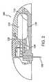
- FIG. 2is a cross-sectional view of an embodiment of an electrochemical system.
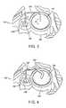
- FIG. 3is a partial perspective view of an embodiment of a fluid delivery system.
- FIG. 4is a partial perspective view of an embodiment of a fluid delivery system.
- FIG. 5is a cross-sectional view of an embodiment of a fluid delivery system.
- FIG. 6is a cross-sectional view of an embodiment of an auxiliary gas source.
- FIG. 7is a cross-sectional view of an embodiment of an auxiliary gas source.
- FIG. 8is a cross-sectional view of an embodiment of an auxiliary gas source.
- FIG. 9is a cross-sectional, schematic view of an embodiment of a fluid delivery device.
- FIG. 10is a schematic diagram of a current controller.
- FIG. 11is a schematic diagram of a current controller.
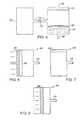
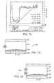
- FIG. 12is a plot of fluid delivery as a function of time.
- FIG. 13is a cross-sectional view of an embodiment of a fluid delivery system.
- FIG. 14is a cross-sectional view of an embodiment of an auxiliary gas source.
- FIG. 15is a cross-sectional view of an embodiment of a fluid delivery system.
- FIG. 16is a cross-sectional view of an embodiment of a fluid delivery device.
- FIG. 17is a schematic representation of an embodiment of a sensor system.
- FIG. 18is a schematic representation of an embodiment of a sensor system.
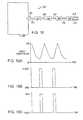
- FIGS. 19A , 19 B, and 19 Care graphical representations of the performance of an embodiment of a sensor.
- FIG. 20is a partial, schematic diagram of an embodiment of a fluid delivery system.
- FIG. 21is a partial, schematic diagram of an embodiment of a fluid delivery system.
- FIG. 22is a partial, schematic diagram of an embodiment of a fluid delivery system.
- FIG. 23is a partial, schematic diagram of an embodiment of a fluid delivery system.
- the inventionrelates to fluid delivery and measurement systems and methods.
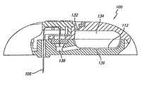
- FIGS. 1 and 2show a fluid delivery system 100 used to deliver one or more fluids such as pharmacological compounds, e.g., one or more therapeutic agents.
- System 100includes a button stopper 102 , a button 104 , a microprobe (e.g., a needle or a microneedle) 106 , a spring 108 , a shell 110 , a bladder 112 , a delivery septum 114 , a positive battery contact 116 , an electrochemical cell 118 , a base 120 , a filling septum 122 , a septum capture ring 124 , a negative battery contact 126 , a battery 128 , a battery spacer 130 , a vent 132 , a drive volume 134 , a fluid volume 136 , and a delivery path 138 .
- a button stopper 102e.g., a button or 104 , a microprobe (e.g., a needle
- a forceis used to urge fluid from the fluid reservoir, into the microprobe and into a subject (e.g., a human).
- the forceis created using an electrochemical cell, such as a fuel cell. Examples of electrochemical cells are disclosed, for example, in U.S. Pat. Nos. 4,402,817; 4,522,698; 4,902,278; and 4,687,423, which are hereby incorporated by reference.
- FIG. 3shows a portion of an embodiment of fluid delivery system 101 .
- System 101includes a septum 140 , a fluid reservoir 142 (e.g., containing a pharmacological compound), a microprobe 144 (e.g., a rigid microprobe, such as a microneedle or a rigid needle) and a housing 146 having an orifice 148 .
- microprobe 144can pierce septum 110 so that microprobe 144 is in fluid communication with fluid reservoir 142 .
- Septum 140 , microprobe 144 , and housing 146can move in the directions indicated by the respective bold arrows (A, B, and C), providing system 101 to have these degrees of freedom.
- FIG. 4shows a portion of a delivery system 150 in which a flexible portion 152 (e.g., a flexible tubing) connects microprobe 144 with a septum 154 .
- a flexible portion 152e.g., a flexible tubing
- Septum 154is stationary, but housing 146 and microprobe 144 can move as indicated by the respective bold arrows (X and Y), providing system 150 with these degrees of freedom.
- housing 146can further include a breakable membrane, such as a polymeric membrane, extending across orifice 148 .
- the membranecan be connected to microprobe 144 to hold the microprobe in place, e.g., centered in orifice 148 , during packing and storage of system 100 .
- a breakable membranesuch as a polymeric membrane
- a fluid delivery systemcan deliver fluid to the subject at a relatively constant rate. Under some circumstances, however, it can be desirable for the system to deliver (at least for a period of time) fluid to the subject at a relatively high rate.
- FIG. 5shows a system 160 including a fluid delivery device 162 and an auxiliary gas source 164 .
- Fluid delivery device 162includes a transport device (e.g., a microprobe or a microneedle or a needle) 166 , a deformable layer (e.g., a deformable membrane) 168 , a fluid reservoir (e.g., a reservoir containing pharmacological compound) 170 , and a gas source 172 .
- Fluid delivery device 162is connected to auxiliary gas source 164 via conduit 174 that includes valve 176 .
- valve 176is generally closed so that device 160 and auxiliary gas source 164 are not in fluid communication.
- fluid delivery device 162delivers fluid from reservoir 168 to the subject via device 162 as follows.
- Gas source 172forms a gas inside device 162 between gas source 172 and layer 168 .
- layer 168is deformed and exerts a pressure against fluid in reservoir 170 , thereby forcing the fluid through device 166 .
- Gas source 172can be, for example, an electrochemical cell, such as a fuel cell that generates oxygen in device 110 , as described above.
- auxiliary gas source 164Under circumstances when it is desirable to deliver (at least for a period of time) fluid to the subject via device 166 at a relatively high rate, the pressure of gas in auxiliary gas source 164 is held at and/or increased to a pressure higher than the gas pressure in device 162 . Valve 176 is then opened, allowing gas to flow from source 164 into device 162 via conduit 174 . This increases the pressure exerted on layer 168 , thereby increasing the rate at which fluid is delivered from reservoir 170 to the subject via device 166 .
- Auxiliary gas source 164can be a body of gas held at a relatively high pressure.
- gas source 164can include a piston 178 that is depressed in conjunction with the opening of valve 176 and a portion 180 that moves as piston 178 is depressed ( FIG. 6 ).
- FIG. 7shows another embodiment in which auxiliary gas source 164 includes a gas source 182 that generates a gas within the auxiliary gas source, such as described above with respect to device 162 .
- gas source 182can be an electrochemical cell as described above.
- auxiliary gas source 164can provide an increased pressure via chemical reactions (e.g., relatively rapid chemical reactions) that occur within the auxiliary gas source (e.g., reactions between vinegar and sodium bicarbonate).
- the gases createdcan be directly added into device 162 , or an increased pressure can be achieved in device 162 by allowing the gases created in the chemical reactions to push, for example, a syringe plunger 184 that increases the gas in device 162 ( FIG. 8 ).
- the gas pressurecan be held at a relatively high value in auxiliary gas source 164 .
- the gas pressure in auxiliary gas source 164is increased just prior to, or at the same time as, valve 176 is opened.
- Valve 176may be manually opened as desired. Valve 176 may be opened at predetermined intervals. Valve 176 may be opened based upon the value of some parameter (e.g., the concentration of an analyte, such as glucose, in a patient).
- some parametere.g., the concentration of an analyte, such as glucose, in a patient.
- a fluid delivery systemit is desirable for a fluid delivery system to deliver a fluid at a predetermined rate, e.g., a variable rate of delivery.
- FIG. 9shows a fluid delivery device 190 that includes a housing 192 and a deformable member (e.g., a deformable membrane) 194 inside the housing.
- Housing 192 and member 194define a first chamber 196 and a second chamber 198 .
- Device 190includes a microprobe 199 , such as a needle or a microneedle, having a lumen in fluid communication with first chamber 196 and an environment outside housing 192 .
- First chamber 196includes a pharmacological compound 200 , such as a, e.g., insulin.
- a pharmacological compound 200such as a, e.g., insulin.
- Second chamber 198includes a button 202 , a current generator 204 , e.g., a DC current generator, in electrical communication with the button, and a gas generator 206 in electrical communication with the generator.
- Gas generator 206is generally as described above.
- a current generator 204e.g., a DC current generator
- gas generator 206is generally as described above.
- a user presses button 202this activates generator 204 , which in turn sends a current to gas generator 206 to create a gas (e.g., oxygen gas) in second chamber 198 .
- a gase.g., oxygen gas
- pressure in second chamber 198increases, which exerts a force on membrane 194 (e.g., pushes membrane toward microprobe 199 ). This, in turn, pushes compound 200 out through the lumen of microprobe 199 to, for example, a subject.
- the rate at which compound 200 is delivered through microprobe 199is controlled by controlling the amount of current that generator 204 produces. This, in turn, controls the amount of gas generated by gas generator 206 , the amount of pressure created in second chamber 198 , and the amount of force exerted on membrane 194 . For example, an increase in current output from current generator 204 increases compound delivery; and a decrease in current output decreases compound delivery.
- the current from current generator 204can be controlled or altered by using a standard current generator having a selector switch configured to alter the resistance in the circuitry of the generator. Current can be increased by switching to a low resistance resistor, and current can be decreased by switching to a high resistance resistor.
- FIGS. 10 and 11show a FET and LM334 current controller, respectively, that can be used to control current by changing resistors. With these current generator systems, the active device can regulate current even with decay in the voltage of the battery.
- the current control generator or systemcan be combined with a software system, e.g., one having a microprocessor, for remote control by the user.
- a software systeme.g., one having a microprocessor
- the therapeutic agentcan be delivered according to a circadian schedule, such as high dosage when the patient is asleep.
- this systempermits an “electronic formulation” or adjustment of therapeutic agent dosage or delivery over the period of ambulation in a delivery system that can, for example, be disposable.
- FIG. 12is a plot of fluid, e.g., a therapeutic agent, delivery (in units per hour) as a function of time.
- FIG. 12shows that the amount of fluid delivery can be controllably varied at least over 24 hours by varying the applied current to current generator 204 .
- a constant current (CC)of about 1,070 microamps was applied, which delivered about 30 units per hour.
- the rate of deliverydecreased to about 3-4 units per hour. Then, the rate of delivery can be increased again by increasing the current.
- the current output from generator 204can be controlled by a variety of ways, including using constant current and/or using constant voltage.
- FIG. 13shows a fluid delivery system 210 including a housing 212 , a gas source 214 , a deformable layer 216 , a transmission device (e.g., a microprobe, a microneedle or a needle) 218 , a fluid reservoir 220 containing a fluid, and a valve 222 .
- System 210delivers fluid from reservoir 220 to a subject when valve 222 is closed and gas source 214 forms a gas inside housing 212 between the gas source and layer 216 .
- layer 216is deformed and exerts a pressure against fluid in reservoir 220 , thereby forcing the fluid through device 218 .
- the gas pressure inside housing 212 between gas source 214 and layer 216can be slightly higher than the ambient gas pressure external to system 210 .
- the change in delivery ratethat is due to the change in the gas pressure differential between the ambient gas pressure external to system 210 and the gas pressure inside housing 212 between gas source 214 and layer 216 .
- a change in the ambient gas pressurefrom 14.7 pounds per square inch (approximate ambient gas pressure at sea level) to 10 pounds per square inch (approximate ambient gas pressure at 15,000 feet), can correspond to an almost 50% increase in the gas volume. This can result in overdelivery of the fluid from reservoir 220 to the subject.
- underdelivery of the fluid from reservoir 220 to the subjectcan occur as the ambient gas pressure external to system 210 undergoes a relatively rapid decrease (e.g., when a plane descends).
- valve 222is designed to open to assist in decreasing a gas pressure differential between the ambient gas pressure external to system 210 and the gas pressure inside housing 212 between gas source 214 and layer 216 .
- valve 222can be a bi-directional valve designed so that when this gas pressure differential meets or exceeds some predetermined value the valve allows gas to flow from the relatively high gas pressure environment to the relatively low gas pressure environment, thereby assisting in decreasing the gas pressure differential.
- Such valvesare commercially available from, for example, Vernay.
- FIG. 14shows a fluid delivery system 230 that contains valves 232 and 234 , each of which is a one-way valve (e.g., a “pop-off” valve, a “mushroom-capped” valve).
- Valves 232 and 234are designed so that, if the ambient external gas pressure to system 210 exceeds the gas pressure inside housing 212 between gas source 214 and layer 216 by some predetermined value, valve 232 opens so that the gas pressure differential decreases.
- Valves 232 and 234are also designed so that, if the gas pressure inside housing 212 between gas source 214 and layer 216 exceeds the ambient external gas pressure to system 210 by some predetermined value, valve 234 opens so that the gas pressure differential decreases.
- Various combinations of pressure relief valvescan be used.
- the combination(s) of relief valve(s)is designed to reduce the gas pressure differential between the internal and external gas pressures of the delivery system when the gas pressure differential meets or exceeds some predetermined value.
- the internal pressure differential at which the device works to provide a desired fluid flowcan be relatively low (e.g., about 0.2 PSIG or less).
- one or more componentscan be included in the device to provide a resistive force to increase the internal pressure differential at which the device works to provide the desired fluid flow.
- a springcan be disposed beneath the flexible member. This can, for example, decrease the absolute and/or relative pressure differential used for pressure relief valve(s) to operate relative the internal pressure differential used to provide desired fluid flow for the device, thereby enhancing the overall sensitivity of the device to changes in the internal/external pressure differential (e.g., due to a change in altitude).
- FIG. 15shows a fluid delivery system 240 including a housing 242 , a gas source 244 , a resilient device 246 (e.g., a spring), an arm 248 (e.g., a drive arm, a cam, a linkage, a ratchet device), a piston 250 , seals 252 and 254 (e.g., O-rings), an actuation device 256 (e.g., a valve actuation arm), and a valve 258 .
- Arm 248is in mechanically coupled to a pumping mechanism 260 (e.g., a deformable layer) that delivers a fluid to a patient via a transmission device, such as a microprobe, a microneedle or a needle.
- a pumping mechanism 260e.g., a deformable layer
- valve 258When valve 258 is closed, gas source 244 forms a gas, which urges piston 250 against device 246 and which moves arm 248 away from source 244 .
- device 256When the piston reaches a position at a predetermined distance from gas source 244 , device 256 causes valve 258 to open, decreasing the gas pressure differential between the interior of housing 242 and the exterior of the housing.
- the position of valve 258e.g., open or closed
- the rate at which piston 250 moves distally from gas source 244can depend upon the differential between the gas pressure inside housing 242 and the gas pressure outside the housing. For example, the amount of time it takes for piston 250 to move a given distance away from gas source 244 can vary proportionally with the variation in the differential in the gas pressure inside housing 242 and the gas pressure outside the housing (e.g., if at a given gas pressure differential it takes piston 250 one second to move a given distance from gas source 244 , then at half that gas pressure differential, it will take piston twice as long to move that distance from the gas source).
- the piston and seals assemblycan be replaced with a bellows sealed to the gas source.
- the circuitry of the gas sourcecan be connected to flip/flop polarity so that it switches, for example, from oxygen generation mode to oxygen removal mode. The polarity can be reversed by, for example, a timed response, a mechanical limit switch, or both.
- the systemcan be designed to not include the return spring or valve actuation arm, and the valve could be replaced with valves described above.
- a fluid delivery system 10includes base 11 positioned thereon, a fluid housing 12 , a needle or microneedle housing 14 , and a movement system 16 for moving the fluid housing.
- Fluid housing 12e.g., a glass cylinder vial, contains a fluid 18 (e.g., a pharmacological compound, such as a drug) between a sealed end 20 and an open end 22 sealed with a pierceable member 24 , such as a rubber stopper or septum.
- Member 24provides fluid housing 12 with a fluid-tight seal so that fluid 18 does not leak from the housing, but member 24 and housing 14 can slide within the housing.
- fluid housing 12is configured to slidably receive member 24 and housing 14 , as described below.
- Housing 14which includes a double-pointed needle 26 , is fixedly attached to base 11 . Examples of housings, including a needle or a microneedle, are described herein.
- Movement system 16includes a gear rack 28 , a pinion gear 30 , a spur gear 32 , and a pawl 34 .
- Gear rack 28has two projections 36 that engage, e.g., hold, ends 20 and 22 of fluid housing 12 to couple the fluid housing to the gear rack.
- Gear rack 28further includes teeth 38 that engage pinion gear 30 , and the pinion gear is rotatably connected to spur gear 32 .
- the gear ratios of gear rack 28 , pinion gear 30 and spur gear 32are selected to provide a predetermined amount of movement of the gear rack in response to a predetermined movement of the spur gear, e.g., sufficient for drug delivery.
- Pawl 34is attached to base 11 at one end and engages with the teeth of spur gear 32 at the other end.
- Pawl 34serves as an anti-reverse mechanism that allows spur gear 32 to rotate in only one direction, here clockwise (arrow A).
- Pawl 34also maintains a load on fluid housing 12 as a drive mechanism (describe below) is reset
- fluid 18is delivered from fluid housing 12 through needle or microneedle 26 by translating fluid housing 12 toward housing 14 (arrow B).
- Spur gear 32is rotated clockwise, which rotates pinion gear 30 clockwise.
- Pawl 34prevents spur gear 32 from rotating counter-clockwise.
- pinion gear 30rotates, its teeth engage with teeth 38 of gear rack 28 , which translates the gear rack in the direction of arrow B. Since gear rack 28 is coupled to fluid housing 12 by projections 36 , the fluid housing is also translated in the direct of arrow B toward housing 14 .
- one end of needle or microneedle 26pierces through member 24
- the other end of the needle or microneedlepierces a subject, e.g., a human.
- Fluid 18is delivered through needle or microneedle 26 by continuing to move fluid housing 12 toward housing 14 with member 24 sliding inside the fluid housing, e.g., like a piston.
- member 24sliding inside the fluid housing, e.g., like a piston.
- fluid 18e.g., a drop or less, flows entirely through the needle or the microneedle before the needle or the microneedle pierces the subject. This can prevent or minimize contamination of fluid 18 , e.g., if the needle or the microneedle pierces the subject first and the subject's bodily fluid can enter fluid housing 12 .
- FIG. 21shows an embodiment of fluid delivery system 10 having a drive mechanism 40 capable of delivering a basal dosage of fluid 18 .
- Mechanism 40includes an inlet port 42 , a piston system 44 , and a driver 46 .
- Port 42is interfaced with a gas-generating source (not shown) such as an electrochemical cell, e.g., an electrolytic cell.
- Gas-generating sourcesare disclosed in U.S. Pat. Nos. 4,402,817; 4,522,698; 4,902,278; and 4,687,423.
- Gas from the gas sourceis provided to drive piston system 44 , which includes a piston 48 and an exhaust port 50 .
- Piston 48is connected to a torsion spring 49 configured to force the piston toward inlet port 42 .
- Piston 48is also connected to driver 46 and linked to exhaust port 50 , e.g., a valve, by a linkage 52 .
- Driver 46is configured to engage with spur gear 32 such that as piston 48 moves away from inlet port 42 , the driver can rotate the spur gear, e.g., clockwise.
- Linkage 52is provided to open exhaust port 50 when piston 48 reaches a predetermined position along its upstroke, e.g., at the end of its stroke, and triggers the linkage. Opening exhaust port 50 vents gas in piston system 44 so that spring 49 can force piston 48 back to an initial stroke position, e.g., adjacent to port 42 . After gas is vented from piston system 44 and piston 48 completes its downstroke, linkage 52 closes exhaust port 50 .
- FIG. 22shows an embodiment of fluid delivery system 10 having a drive mechanism 54 capable of delivering a bolus dosage of fluid 18 .
- Mechanism 54is shown in an untriggered condition.
- Mechanism 54includes a shaft 56 , a button release lever 58 , and a button lock-up bar 60 .
- Shaft 56includes positioned thereon a button 62 , a button extension spring 64 , a bolus actuator 66 , and a bolus drive spring 68 .
- Button 62 and actuator 66are slidably positioned on shaft 56 .
- Button 62is a square, hollow member having a notch 70 .
- Springs 64 and 68are positioned on shaft 56 such that they can be compressed and extended on the shaft when button 62 and actuator 66 are moved along the shaft.
- Actuator 66is also a square, hollow member that includes an actuator tab 72 , e.g., spring steel, that can engage with the teeth of spur gear 32 to rotate the spur gear, e.g., drive the gear in the direction of arrow A.
- Shaft 56is connected to base 11 on one end.
- Button release lever 58is pivotally connected to base 11 at connection 74 .
- Lever 58is biased in the direction of arrow C by a lever spring 76 .
- Leverincludes a portion 88 that can engage with notch 70 .
- Button lock-up bar 60is also pivotally connected to base 11 , at connection 78 .
- Button lock-up bar 60is biased in the direction of arrow D by a spring (not shown).
- Button lock-up bar 60includes an edge 80 that is chamfered, e.g., at about 45°, and that contacts an end 82 of bolus actuator 66 when mechanism 54 is in an untriggered condition.
- Lock-up bar 60further includes an end 84 that can engage with an end 86 of button 62 .
- button release lever 58is spring-biased in the direction of arrow C
- button lock-up bar 60is spring-biased in the direction of arrow D.
- Springs 64 and 68are extended.
- button 62shown extended in FIG. 22
- button 62also compresses springs 64 and 68 along shaft 56 and moves bolus actuator 66 and tab 72 in the direction of arrow E.
- Tab 72deflects as it travels over the teeth of spur gear 32 .
- lock-up bar 60is biased in the direction of arrow D, and bolus actuator 66 has been moved out of contact with edge 80 by depressing button 62 , the lock-up bar rotates (arrow D) about connection 78 , and end 84 rotates to contact the side of the button. With button 62 depressed and locked, drive mechanism 54 is in a “cocked” condition.
- button release lever 58To trigger drive mechanism 54 , the user rotates button release lever 58 about connection 74 in the direction opposite arrow C, here clockwise. This releases the locking engagement between notch 70 and portion 88 , and allows button 62 to be returned to its untriggered position by the spring force of spring 64 . Similarly, bolus actuator 66 is returned to its untriggered position by the controlled and predetermined spring force of spring 68 . As bolus actuator 66 returns (in the direction opposite arrow E) actuator tab 72 engages spur gear 32 at a controlled force and rotates the spur gear, thereby delivering a bolus dose at a controlled rate.
- edge 82contacts edge 80 to rotate lock-up bar 60 in the direction opposite arrow D, thereby moving end 84 away from end 86 and allowing button 62 to be depressed.
- lock-up bar 60is biased in the direction of arrow D (upwardly as shown in FIG. 22 ); such that, if the user tried to depress button 62 , end 84 would butt against end 86 and prevent the button from being depressed. This mechanism prevents the user from re-cocking and re-triggering the bolus delivery mechanism before the bolus dosage is completed.
- Each trigger of drive mechanism 54can provide a predetermined bolus dosage at a controlled rate, so the risk of under-dosage is minimized.
- the useris prevented from re-triggering the drive mechanism until the predetermined dosage is delivered, so the risk of over-dosage is minimized.
- drive mechanisms 40 and 54are described above separately, in certain embodiments, the drive mechanisms are integrated in a fluid delivery system such that the delivery system can deliver a basal dosage and a bolus dosage on demand.
- FIG. 23shows an embodiment of a piston system 1100 that can be used in drive mechanism 40 described above.
- System 1100includes a piston assembly 1102 , a linkage assembly 1104 , and a valve 1106 , e.g., a T-shape valve.
- Piston assembly 1102includes a piston 1108 , a piston housing 1110 , and a spring 1111 .
- Spring 1111is configured to bias piston 1108 , e.g., with linear force, in the direction of arrow F, for example, to bias the piston to a position adjacent to valve 1106 .
- piston 1108is connected to driver 46 in the drive mechanism described above to delivery fluid 18 .
- Piston assembly 1102further includes a gas inlet 1113 that is in fluid communication with the interior of housing 1110 and a gas source (not shown), such as an electrochemical cell described above.
- Linkage assembly 1104includes a first lever arm 1112 , a linkage bar 1114 , and a second lever arm 1116 .
- First lever arm 1112is connected to linkage bar 1114 by a freely pivoting connection; and the linkage bar is connected to second lever arm 1116 by a slotted connection 1118 and to valve 1106 .
- First lever arm 1112is further engaged to a ball plunger 1120 via a first detent 1124 or a second detent 1126 on the first lever arm.
- ball plunger 1120includes a ball 1122 that can rest in first detent 1124 or second detent 1126 .
- plunger 1120is fixedly connected, for example, to a housing of system 1100 via a spring or a rigid connection.
- Linkage assembly 1104is connected to piston 1108 at one end of first lever arm 1112 , for example, by a spring or a rigid connection such as a rod.
- piston 1108is at an initial position, e.g., adjacent to valve 1106 .
- Linkage assembly 1104is configured such that the pivoting and lever action of lever arms 1112 and 1116 and linkage bar 1114 causes the valve to be closed.
- Piston housing 1110is sealed.
- Ball 1122is at rest in first detent 1124 .
- Piston 1108is moved away from valve 1106 . The movement of piston 1108 can be used to drive driver 46 to deliver a fluid.
- piston 1108When piston 1108 reaches a predetermined position, e.g., at the end of its upstroke, the piston pushes on first lever arm 1112 such that ball 1122 is displaced from first detent 1124 to second detent 1126 .
- This actioncauses linkage assembly 104 (by pivoting and lever action) to open valve 1106 . Opening valve 1106 vents gas from piston housing 1110 , and the spring force of spring 1111 causes piston 1108 to return to its initial position.
- ball 1122As piston 1108 travels back to its initial position, ball 1122 is still in second detent 1126 , thereby ensuring that valve 1106 stays open until the piston returns to a predetermined position, e.g., its initial position, i.e., for the entire return stroke.
- piston 1108could be stalled midway through the entire stroke cycle.
- piston 1108pushes and closes valve 1106 , and the mechanical action of linkage assembly 1104 displaces ball 1122 from second detent 1126 to first detent 1124 .
- the stroke cycle of the pistonis repeated as gas is introduced into housing 1110 .
- system 1100is generally configured to ensure that piston 1108 completes its stroke cycle, e.g., from an initial position to a final position and back to the initial position, without restarting its cycle during the cycle.
- system 1100can provide an accurate and reliable drive mechanism.
- FIG. 16shows a system 270 that includes a first chamber 272 and a second chamber 274 .
- Chamber 272contains a diluent reservoir 276 coupled to a button 278 via a piston 280 so that when the button is depressed, the piston moves in the direction shown by the arrows.
- Thiscauses the diluent to move along a path 282 and enter a powder chamber 284 , which contains a dried powder, such as, for example, a pharmacological compound (e.g., a lyophilized therapeutic agent).
- a pharmacological compounde.g., a lyophilized therapeutic agent
- the reconstituted mixture(e.g., therapeutic agent/diluent mixture) can move along a path 286 to a seal 288 .
- Seal 288can be, for example, a sterility seal. If seal 288 is broken (e.g., by being sheared as system 270 is mounted on, for example, a subject), then the reconstituted mixture can pass into a reservoir 290 contained in chamber 274 .
- Chamber 274also includes a gas source 292 as described above, a deformable layer 294 , and a transmission device 296 (e.g., a needle or a microneedle).
- gas source 292When gas source 292 is activated (e.g., by the user pressing a button), the gas source creates a gas in housing 274 between the gas source and deformable layer 294 . This exerts a force on deformable layer 294 , which, in turn, causes fluid (e.g., a fluid and the therapeutic agent/diluent mixture) in reservoir 290 to exit housing 274 via device 296 .
- the fluidis transferred into a subject (e.g., a human) (e.g., when device 296 is inserted into the subject).
- the usercan press a button that activates (e.g., simultaneously activates) both the electrochemical cell and causes the transmission device to be inserted into the subject so that a fluid path is connected between the fluid reservoir and the subject.
- the actionscan be performed sequentially using detents or partial mechanical stops during travel of the button.
- a fluid delivery systemcan be adapted for use as a sensor.
- FIG. 17shows an embodiment of a sensor system 300 including a microprobe 302 , a sensor 304 , a pump 306 and a subject (e.g., a human) 308 .
- Microprobe 302is in fluid communication with sensor 304 via a fluid path (e.g., tubing) 310
- the sensoris in fluid communication with pump 306 via a fluid path (e.g., tubing) 312 .
- pump 306creates a suction or partial vacuum that can remove a sample (e.g., a fluid sample, such as a blood sample) from subject 308 .
- a samplee.g., a fluid sample, such as a blood sample
- the samplepasses through microprobe 302 (e.g., a needle or a microneedle) and along path 310 to sensor 304 (e.g., a blood glucose sensor), where one or more species of interest (e.g., analytes of interest, such as glucose) is measured.
- the samplethen moves along path 312 to pump 306 and exits system 300 via an exhaust 314 (e.g., a gas exhaust) and/or exhaust 316 (e.g., a waste exhaust).
- Exhaust 314 and/or 316can be in fluid communication with, for example, a disposable bag.
- pump 306is an electrochemical cell that operates in reverse mode so that it removes oxygen present between microprobe 302 and sensor 304 (e.g., in microprobe 302 , path 310 , the sensor, path 312 and/or the pump) and exhausts via exhaust 314 . By using up this oxygen, pump 306 reduces the pressure between microprobe 302 and sensor 304 , thereby creating suction or a partial vacuum and allowing the sample to be removed from subject 308 . Because there is only about 20% oxygen in air, the suction created by the electrochemical cell can be limited.
- An example of an electrochemical cellis a symmetrical Pt/NAFION® fuel cell. Examples of electrochemical cells are described above.
- FIG. 18shows an embodiment of a sensor system 320 that includes a flow restriction device (e.g., a valve clamp) 322 and a re-fill device (e.g., a re-fill valve) 324 .
- a flow restriction devicee.g., a valve clamp
- a re-fill devicee.g., a re-fill valve
- pump 306creates a suction or partial vacuum that can remove a sample (e.g., a fluid sample, such as a blood sample) from subject 308 .
- a samplee.g., a fluid sample, such as a blood sample
- the samplepasses through microprobe 302 and along a path 326 (e.g., tubing) to flow restriction device 322 .
- the samplethen passes along a path 328 (e.g., tubing) to sensor 304 .
- the samplethen passes along a path 330 (e.g., tubing) to re-fill device 324 .
- the samplethen passes along a path (e.g., tubing) 332 to pump 306 , and then out of system 320 via exhaust 314 and/or 316 .
- Device 324can be used to periodically (e.g., at predetermined and/or timed intervals, and/or at intervals determined in response to a signal, such as a measurement of the amount of oxygen in fluid communication with path 330 , path 332 and/or device 324 ) re-fill air into system 320 , thereby allowing continuous or semi-continuous extraction of fluid from subject 308 via microprobe 302 .
- a signalsuch as a measurement of the amount of oxygen in fluid communication with path 330 , path 332 and/or device 324
- device 322can be closed to prevent fluid communication between subject 304 and sensor 304 .
- FIG. 19Ashows an embodiment of oxygen values as a function of time for system 320 .
- FIGS. 19B and 19Cshow the corresponding values of the position (i.e., open/closed) of devices 322 and 324 , respectively, as a function of time for system 320 .
- more than one electrochemical cellcan be used to provide suction in an alternating pattern to provide continuous or semi-continuous extraction of fluid from subject 308 .
- Pump 306can be placed in various positions so long as it is capable of forming suction or a partial vacuum as discussed above.
- pump 306is between microprobe 302 and sensor 304 .
- Therapeutic agents that can be used in the devices and methods described hereininclude, for example, vaccines, chemotherapy agents, pain relief agents, dialysis-related agents, blood thinning agents, and compounds (e.g., monoclonal compounds) that can be targeted to carry compounds that can kill cancer cells.
- examples of such agentsinclude, insulin, heparin, morphine, interferon, EPO, vaccines towards tumors, and vaccines towards infectious diseases.
- the devicecan be used to deliver a therapeutic agent to any primate, including human and non-human primates.
- the devicecan be used to deliver an agent, e.g., a therapeutic agent to an animal, e.g., a farm animal (such as a horse, cow, sheep, goat, or pig), to a laboratory animal (such as a mouse, rat, guinea pig or other rodent), or to a domesticated animal (such as a dog or cat).
- the animal to which the therapeutic agent is being deliveredcan have any ailment (e.g., cancer or diabetes). It is expected that the device may be most useful in treating chronic conditions.
- the devicecan also be used to deliver a therapeutic agent (such as a vaccine) to an animal that is not suffering from an ailment (or that is suffering from an ailment unrelated to that associated with the therapeutic agent). That is, the device can be used to deliver therapeutic agents prophylactically.
- a therapeutic agentsuch as a vaccine
- the devices and methods of the inventioncan be used to individually tailor the dosage of a therapeutic agent to a patient.
- the devices and methods of the inventioncan allow for outpatient treatment with increased convenience, such as, for example, without the use of an I.V.
- Devices and methods described hereincan be advantageous because they can be used to promote maintenance of the concentration of a therapeutic agent in a patient's plasma within a safe and effective range. Moreover, the device can release therapeutic agents in response to the concentration of an analyte in the patient's system. Thus, the rate of drug delivery can be appropriate for the patient's physiological state as it changes, e.g., from moment to moment.
Landscapes
- Health & Medical Sciences (AREA)
- Life Sciences & Earth Sciences (AREA)
- General Health & Medical Sciences (AREA)
- Engineering & Computer Science (AREA)
- Anesthesiology (AREA)
- Biomedical Technology (AREA)
- Heart & Thoracic Surgery (AREA)
- Vascular Medicine (AREA)
- Hematology (AREA)
- Animal Behavior & Ethology (AREA)
- Veterinary Medicine (AREA)
- Public Health (AREA)
- Physics & Mathematics (AREA)
- Fluid Mechanics (AREA)
- Dermatology (AREA)
- Infusion, Injection, And Reservoir Apparatuses (AREA)
- Sampling And Sample Adjustment (AREA)
Abstract
Description
Claims (19)
Priority Applications (7)
| Application Number | Priority Date | Filing Date | Title |
|---|---|---|---|
| US12/336,246US8858511B2 (en) | 2000-11-30 | 2008-12-16 | Fluid delivery and measurement systems and methods |
| US13/743,892US8992478B2 (en) | 2000-11-30 | 2013-01-17 | Fluid delivery and measurement systems and methods |
| US14/629,801US9636451B2 (en) | 2000-11-30 | 2015-02-24 | Fluid delivery and measurement systems and methods |
| US15/464,570US9981083B2 (en) | 2000-11-30 | 2017-03-21 | Fluid delivery and measurement systems and methods |
| US15/966,030US10610640B2 (en) | 2000-11-30 | 2018-04-30 | Fluid delivery and measurement systems and methods |
| US16/801,806US20200206418A1 (en) | 2000-11-30 | 2020-02-26 | Fluid Delivery and Measurement Systems and Methods |
| US17/842,564US20220313902A1 (en) | 2000-11-30 | 2022-06-16 | Fluid Delivery and Measurement Systems and Methods |
Applications Claiming Priority (11)
| Application Number | Priority Date | Filing Date | Title |
|---|---|---|---|
| US25041300P | 2000-11-30 | 2000-11-30 | |
| US25029500P | 2000-11-30 | 2000-11-30 | |
| US25042200P | 2000-11-30 | 2000-11-30 | |
| US25040300P | 2000-11-30 | 2000-11-30 | |
| US25092700P | 2000-11-30 | 2000-11-30 | |
| US25040800P | 2000-11-30 | 2000-11-30 | |
| US25053800P | 2000-11-30 | 2000-11-30 | |
| US32441201P | 2001-09-24 | 2001-09-24 | |
| US10/006,526US6939324B2 (en) | 2000-11-30 | 2001-11-30 | Fluid delivery and measurement systems and methods |
| US11/219,944US7481792B2 (en) | 2000-11-30 | 2005-09-06 | Fluid delivery and measurement systems and methods |
| US12/336,246US8858511B2 (en) | 2000-11-30 | 2008-12-16 | Fluid delivery and measurement systems and methods |
Related Parent Applications (1)
| Application Number | Title | Priority Date | Filing Date |
|---|---|---|---|
| US11/219,944DivisionUS7481792B2 (en) | 2000-11-30 | 2005-09-06 | Fluid delivery and measurement systems and methods |
Related Child Applications (1)
| Application Number | Title | Priority Date | Filing Date |
|---|---|---|---|
| US13/743,892ContinuationUS8992478B2 (en) | 2000-11-30 | 2013-01-17 | Fluid delivery and measurement systems and methods |
Publications (2)
| Publication Number | Publication Date |
|---|---|
| US20090093763A1 US20090093763A1 (en) | 2009-04-09 |
| US8858511B2true US8858511B2 (en) | 2014-10-14 |
Family
ID=27575279
Family Applications (9)
| Application Number | Title | Priority Date | Filing Date |
|---|---|---|---|
| US10/006,526Expired - LifetimeUS6939324B2 (en) | 2000-11-30 | 2001-11-30 | Fluid delivery and measurement systems and methods |
| US11/219,944Expired - LifetimeUS7481792B2 (en) | 2000-11-30 | 2005-09-06 | Fluid delivery and measurement systems and methods |
| US12/336,246Expired - LifetimeUS8858511B2 (en) | 2000-11-30 | 2008-12-16 | Fluid delivery and measurement systems and methods |
| US13/743,892Expired - Fee RelatedUS8992478B2 (en) | 2000-11-30 | 2013-01-17 | Fluid delivery and measurement systems and methods |
| US14/629,801Expired - Fee RelatedUS9636451B2 (en) | 2000-11-30 | 2015-02-24 | Fluid delivery and measurement systems and methods |
| US15/464,570Expired - LifetimeUS9981083B2 (en) | 2000-11-30 | 2017-03-21 | Fluid delivery and measurement systems and methods |
| US15/966,030Expired - Fee RelatedUS10610640B2 (en) | 2000-11-30 | 2018-04-30 | Fluid delivery and measurement systems and methods |
| US16/801,806AbandonedUS20200206418A1 (en) | 2000-11-30 | 2020-02-26 | Fluid Delivery and Measurement Systems and Methods |
| US17/842,564AbandonedUS20220313902A1 (en) | 2000-11-30 | 2022-06-16 | Fluid Delivery and Measurement Systems and Methods |
Family Applications Before (2)
| Application Number | Title | Priority Date | Filing Date |
|---|---|---|---|
| US10/006,526Expired - LifetimeUS6939324B2 (en) | 2000-11-30 | 2001-11-30 | Fluid delivery and measurement systems and methods |
| US11/219,944Expired - LifetimeUS7481792B2 (en) | 2000-11-30 | 2005-09-06 | Fluid delivery and measurement systems and methods |
Family Applications After (6)
| Application Number | Title | Priority Date | Filing Date |
|---|---|---|---|
| US13/743,892Expired - Fee RelatedUS8992478B2 (en) | 2000-11-30 | 2013-01-17 | Fluid delivery and measurement systems and methods |
| US14/629,801Expired - Fee RelatedUS9636451B2 (en) | 2000-11-30 | 2015-02-24 | Fluid delivery and measurement systems and methods |
| US15/464,570Expired - LifetimeUS9981083B2 (en) | 2000-11-30 | 2017-03-21 | Fluid delivery and measurement systems and methods |
| US15/966,030Expired - Fee RelatedUS10610640B2 (en) | 2000-11-30 | 2018-04-30 | Fluid delivery and measurement systems and methods |
| US16/801,806AbandonedUS20200206418A1 (en) | 2000-11-30 | 2020-02-26 | Fluid Delivery and Measurement Systems and Methods |
| US17/842,564AbandonedUS20220313902A1 (en) | 2000-11-30 | 2022-06-16 | Fluid Delivery and Measurement Systems and Methods |
Country Status (6)
| Country | Link |
|---|---|
| US (9) | US6939324B2 (en) |
| EP (3) | EP2578252B1 (en) |
| AU (1) | AU2002241567A1 (en) |
| CA (1) | CA2430590C (en) |
| ES (3) | ES2717656T3 (en) |
| WO (1) | WO2002055128A2 (en) |
Cited By (7)
| Publication number | Priority date | Publication date | Assignee | Title |
|---|---|---|---|---|
| US20150165115A1 (en)* | 2000-11-30 | 2015-06-18 | Valeritas, Inc. | Fluid Delivery and Measurement Systems and Methods |
| US10182969B2 (en) | 2015-03-10 | 2019-01-22 | Regeneron Pharmaceuticals, Inc. | Aseptic piercing system and method |
| US10814062B2 (en) | 2017-08-31 | 2020-10-27 | Becton, Dickinson And Company | Reservoir with low volume sensor |
| US11278665B2 (en) | 2016-11-22 | 2022-03-22 | Eitan Medical Ltd. | Method for delivering a therapeutic substance |
| US11357909B2 (en) | 2018-10-05 | 2022-06-14 | Eitan Medical Ltd. | Triggering sequence |
| US11547801B2 (en) | 2017-05-05 | 2023-01-10 | Regeneron Pharmaceuticals, Inc. | Auto-injector |
| USD1007676S1 (en) | 2021-11-16 | 2023-12-12 | Regeneron Pharmaceuticals, Inc. | Wearable autoinjector |
Families Citing this family (223)
| Publication number | Priority date | Publication date | Assignee | Title |
|---|---|---|---|---|
| US7850663B2 (en)* | 2001-01-12 | 2010-12-14 | Becton, Dickinson And Company | Medicament microdevice delivery system, cartridge and method of use |
| CA2499838C (en)* | 2001-09-21 | 2012-12-18 | Biovalve Technologies, Inc. | Gas pressure actuated microneedle arrays, and systems and methods relating to same |
| US7429258B2 (en) | 2001-10-26 | 2008-09-30 | Massachusetts Institute Of Technology | Microneedle transport device |
| GB0210397D0 (en) | 2002-05-07 | 2002-06-12 | Ferring Bv | Pharmaceutical formulations |
| CN1691969A (en) | 2002-07-19 | 2005-11-02 | 3M创新有限公司 | Microneedle devices and microneedle application equipment |
| EP1386626A1 (en)* | 2002-07-31 | 2004-02-04 | Novo Nordisk A/S | Delivery device for treatment of diabetes mellitus |
| NZ539120A (en)* | 2002-09-19 | 2006-09-29 | I Flow Corp | Device for selectively regulating the flow rate of a fluid |
| US7381184B2 (en) | 2002-11-05 | 2008-06-03 | Abbott Diabetes Care Inc. | Sensor inserter assembly |
| WO2004094823A2 (en) | 2003-04-23 | 2004-11-04 | Biovalve Technologies, Inc. | Hydraulically actuated pump for long duration medicament administration |
| ATE392223T1 (en) | 2003-05-08 | 2008-05-15 | Novo Nordisk As | INTERNAL NEEDLE INTRODUCER |
| JP4509100B2 (en) | 2003-05-08 | 2010-07-21 | ノボ・ノルデイスク・エー/エス | Infusion device attachable to skin with removable needle insertion actuation |
| EP1475113A1 (en)* | 2003-05-08 | 2004-11-10 | Novo Nordisk A/S | External needle inserter |
| ES2279409T3 (en)* | 2003-05-30 | 2007-08-16 | Eli Lilly And Company | MEDICATION DISPENSATION DEVICE FOR MULTIPLE CAMERAS. |
| ATE529154T1 (en)* | 2003-06-02 | 2011-11-15 | Becton Dickinson Co | MICRO DEVICE FOR A MEDICINE DELIVERY SYSTEM HAVING A CARTRIDGE |
| EP1502613A1 (en) | 2003-08-01 | 2005-02-02 | Novo Nordisk A/S | Needle device with retraction means |
| AU2004268616B2 (en) | 2003-08-25 | 2010-10-07 | 3M Innovative Properties Company | Delivery of immune response modifier compounds |
| US7066029B2 (en) | 2003-09-25 | 2006-06-27 | Deka Products Limited Partnership | System and method for improved volume measurement |
| EP1527792A1 (en)* | 2003-10-27 | 2005-05-04 | Novo Nordisk A/S | Medical injection device mountable to the skin |
| WO2005037350A2 (en)* | 2003-10-21 | 2005-04-28 | Novo Nordisk A/S | Internal fluid connector for establishing a fluid connection |
| KR20060099520A (en)* | 2003-10-21 | 2006-09-19 | 노보 노르디스크 에이/에스 | Medical Skin Mounting Device |
| USD902408S1 (en) | 2003-11-05 | 2020-11-17 | Abbott Diabetes Care Inc. | Analyte sensor control unit |
| SG179411A1 (en) | 2003-11-06 | 2012-04-27 | Lifescan Inc | Drug delivery pen with event notification means |
| DE10360186A1 (en)* | 2003-12-20 | 2005-08-04 | Max Wyssmann | Device for the targeted, controllable delivery of a liquid or a viscous mass |
| JP2007516781A (en)* | 2003-12-29 | 2007-06-28 | スリーエム イノベイティブ プロパティズ カンパニー | Medical device and kit including the medical device |
| WO2005082596A1 (en)* | 2004-02-23 | 2005-09-09 | 3M Innovative Properties Company | Method of molding for microneedle arrays |
| CN100586495C (en) | 2004-03-30 | 2010-02-03 | 诺和诺德公司 | Actuator system comprising lever mechanism |
| US8057434B2 (en) | 2004-03-31 | 2011-11-15 | Eli Lilly And Company | Injection apparatus having a needle cassette for delivering a pharmaceutical liquid |
| US9089636B2 (en) | 2004-07-02 | 2015-07-28 | Valeritas, Inc. | Methods and devices for delivering GLP-1 and uses thereof |
| WO2006014901A1 (en)* | 2004-07-27 | 2006-02-09 | Eli Lilly And Company | Multiple septum cartridge for medication dispensing device |
| US8491456B2 (en)* | 2004-08-26 | 2013-07-23 | Song Park | Method and apparatus providing a symbol sequence to a user, and wearable infrastructure providing the symbol sequence to the body |
| AT501250B1 (en)* | 2004-09-22 | 2007-03-15 | Pro Med Medizinische Produktio | DEVICE FOR DOSED RECORDING AND DISTRIBUTION OF LIQUID |
| JP2008520369A (en) | 2004-11-18 | 2008-06-19 | スリーエム イノベイティブ プロパティズ カンパニー | Inconspicuous microneedle array applicator |
| CA2587387C (en) | 2004-11-18 | 2013-06-25 | 3M Innovative Properties Company | Method of contact coating a microneedle array |
| US8057842B2 (en) | 2004-11-18 | 2011-11-15 | 3M Innovative Properties Company | Method of contact coating a microneedle array |
| US9174035B2 (en) | 2004-11-18 | 2015-11-03 | 3M Innovative Properties Company | Microneedle array applicator and retainer |
| JP4927751B2 (en)* | 2004-11-18 | 2012-05-09 | スリーエム イノベイティブ プロパティズ カンパニー | Microneedle array coating method |
| CN102358015A (en) | 2004-12-07 | 2012-02-22 | 3M创新有限公司 | Method of molding a microneedle |
| US8333714B2 (en) | 2006-09-10 | 2012-12-18 | Abbott Diabetes Care Inc. | Method and system for providing an integrated analyte sensor insertion device and data processing unit |
| US10226207B2 (en) | 2004-12-29 | 2019-03-12 | Abbott Diabetes Care Inc. | Sensor inserter having introducer |
| US7883464B2 (en) | 2005-09-30 | 2011-02-08 | Abbott Diabetes Care Inc. | Integrated transmitter unit and sensor introducer mechanism and methods of use |
| US9788771B2 (en) | 2006-10-23 | 2017-10-17 | Abbott Diabetes Care Inc. | Variable speed sensor insertion devices and methods of use |
| US20090105569A1 (en) | 2006-04-28 | 2009-04-23 | Abbott Diabetes Care, Inc. | Introducer Assembly and Methods of Use |
| US8029441B2 (en) | 2006-02-28 | 2011-10-04 | Abbott Diabetes Care Inc. | Analyte sensor transmitter unit configuration for a data monitoring and management system |
| US8571624B2 (en) | 2004-12-29 | 2013-10-29 | Abbott Diabetes Care Inc. | Method and apparatus for mounting a data transmission device in a communication system |
| US8512243B2 (en) | 2005-09-30 | 2013-08-20 | Abbott Diabetes Care Inc. | Integrated introducer and transmitter assembly and methods of use |
| US7697967B2 (en) | 2005-12-28 | 2010-04-13 | Abbott Diabetes Care Inc. | Method and apparatus for providing analyte sensor insertion |
| US9398882B2 (en) | 2005-09-30 | 2016-07-26 | Abbott Diabetes Care Inc. | Method and apparatus for providing analyte sensor and data processing device |
| US9572534B2 (en) | 2010-06-29 | 2017-02-21 | Abbott Diabetes Care Inc. | Devices, systems and methods for on-skin or on-body mounting of medical devices |
| US9743862B2 (en) | 2011-03-31 | 2017-08-29 | Abbott Diabetes Care Inc. | Systems and methods for transcutaneously implanting medical devices |
| US7731657B2 (en) | 2005-08-30 | 2010-06-08 | Abbott Diabetes Care Inc. | Analyte sensor introducer and methods of use |
| US9259175B2 (en) | 2006-10-23 | 2016-02-16 | Abbott Diabetes Care, Inc. | Flexible patch for fluid delivery and monitoring body analytes |
| US8167841B2 (en) | 2005-01-24 | 2012-05-01 | Novo Nordisk A/S | Transcutaneous device assembly |
| EP1866009A1 (en)* | 2005-02-25 | 2007-12-19 | Novo Nordisk A/S | Pump assembly with safety valve |
| EP1871459B1 (en) | 2005-04-07 | 2019-06-19 | 3M Innovative Properties Company | System for tool feedback sensing |
| WO2006108809A1 (en) | 2005-04-13 | 2006-10-19 | Novo Nordisk A/S | Medical skin mountable device and system |
| US20080097291A1 (en)* | 2006-08-23 | 2008-04-24 | Hanson Ian B | Infusion pumps and methods and delivery devices and methods with same |
| US8840586B2 (en) | 2006-08-23 | 2014-09-23 | Medtronic Minimed, Inc. | Systems and methods allowing for reservoir filling and infusion medium delivery |
| US7699833B2 (en) | 2005-05-06 | 2010-04-20 | Moberg Sheldon B | Pump assembly and method for infusion device |
| US8137314B2 (en)* | 2006-08-23 | 2012-03-20 | Medtronic Minimed, Inc. | Infusion medium delivery device and method with compressible or curved reservoir or conduit |
| US7905868B2 (en) | 2006-08-23 | 2011-03-15 | Medtronic Minimed, Inc. | Infusion medium delivery device and method with drive device for driving plunger in reservoir |
| US8277415B2 (en) | 2006-08-23 | 2012-10-02 | Medtronic Minimed, Inc. | Infusion medium delivery device and method with drive device for driving plunger in reservoir |
| US8512288B2 (en) | 2006-08-23 | 2013-08-20 | Medtronic Minimed, Inc. | Infusion medium delivery device and method with drive device for driving plunger in reservoir |
| EP1904158B1 (en) | 2005-06-24 | 2013-07-24 | 3M Innovative Properties Company | Collapsible patch with microneedle array |
| EP1896115B2 (en) | 2005-06-27 | 2020-01-22 | 3M Innovative Properties Company | Microneedle cartridge assembly |
| EP1901799B1 (en) | 2005-06-27 | 2012-06-13 | 3M Innovative Properties Company | Microneedle array applicator device |
| EP1762259B2 (en)* | 2005-09-12 | 2025-01-01 | Unomedical A/S | Inserter for an infusion set with a first and second spring units |
| US20090118682A1 (en)* | 2005-09-13 | 2009-05-07 | Novo Nordisk A/S | Reservoir Device With Inspection Aid For Detection Of Drug Condition |
| US9521968B2 (en) | 2005-09-30 | 2016-12-20 | Abbott Diabetes Care Inc. | Analyte sensor retention mechanism and methods of use |
| WO2007045644A1 (en)* | 2005-10-17 | 2007-04-26 | Novo Nordisk A/S | Vented drug reservoir unit |
| US8900180B2 (en)* | 2005-11-18 | 2014-12-02 | 3M Innovative Properties Company | Coatable compositions, coatings derived therefrom and microarrays having such coatings |
| US20080262416A1 (en)* | 2005-11-18 | 2008-10-23 | Duan Daniel C | Microneedle Arrays and Methods of Preparing Same |
| DK1962926T3 (en) | 2005-12-23 | 2009-09-28 | Unomedical As | injection device |
| US11298058B2 (en) | 2005-12-28 | 2022-04-12 | Abbott Diabetes Care Inc. | Method and apparatus for providing analyte sensor insertion |
| CA2636034A1 (en) | 2005-12-28 | 2007-10-25 | Abbott Diabetes Care Inc. | Medical device insertion |
| SI1986612T1 (en) | 2006-02-07 | 2013-01-31 | Shire Human Genetic Therapies, Inc. | Stabilized composition of glucocerebrosidase |
| EP3165247B1 (en) | 2006-02-09 | 2020-10-28 | DEKA Products Limited Partnership | Pumping fluid delivery systems and methods using force application assembley |
| WO2007098771A2 (en) | 2006-02-28 | 2007-09-07 | Unomedical A/S | Inserter for infusion part and infusion part provided with needle protector |
| EP1997233B1 (en) | 2006-03-13 | 2014-03-05 | Novo Nordisk A/S | Secure pairing of electronic devices using dual means of communication |
| WO2007115039A2 (en) | 2006-03-30 | 2007-10-11 | Valeritas, Llc | Multi-cartridge fluid delivery device |
| US9119945B2 (en) | 2006-04-20 | 2015-09-01 | 3M Innovative Properties Company | Device for applying a microneedle array |
| EP2032188A1 (en) | 2006-06-06 | 2009-03-11 | Novo Nordisk A/S | Assembly comprising skin-mountable device and packaging therefore |
| CA2653764A1 (en) | 2006-06-09 | 2007-12-13 | Unomedical A/S | Mounting pad |
| US20080015494A1 (en)* | 2006-07-11 | 2008-01-17 | Microchips, Inc. | Multi-reservoir pump device for dialysis, biosensing, or delivery of substances |
| ATE426358T1 (en)* | 2006-07-22 | 2009-04-15 | Hoffmann La Roche | PORTABLE MEASURING DEVICE FOR DETERMINING A MEDICALLY SIGNIFICANT ANALYTE CONCENTRATION |
| JP2009545341A (en)* | 2006-08-02 | 2009-12-24 | ウノメディカル アクティーゼルスカブ | Cannula and delivery device |
| US7811262B2 (en) | 2006-08-23 | 2010-10-12 | Medtronic Minimed, Inc. | Systems and methods allowing for reservoir filling and infusion medium delivery |
| US7794434B2 (en) | 2006-08-23 | 2010-09-14 | Medtronic Minimed, Inc. | Systems and methods allowing for reservoir filling and infusion medium delivery |
| US7682338B2 (en)* | 2006-08-23 | 2010-03-23 | Medtronic Minimed, Inc. | Infusion medium delivery system, device and method with needle inserter and needle inserter device and method |
| US7828764B2 (en) | 2006-08-23 | 2010-11-09 | Medtronic Minimed, Inc. | Systems and methods allowing for reservoir filling and infusion medium delivery |
| US7547293B2 (en) | 2006-10-06 | 2009-06-16 | Bioject, Inc. | Triggering mechanism for needle-free injector |
| WO2008075651A1 (en)* | 2006-12-19 | 2008-06-26 | National Institute Of Advanced Industrial Science And Technology | Biosensor cartridge, method of using biosensor cartridge, biosensor device and needle-integrated sensor |
| US7744563B2 (en) | 2007-02-23 | 2010-06-29 | Bioject, Inc. | Needle-free injection devices and drug delivery systems therefor |
| US8113390B2 (en)* | 2007-04-18 | 2012-02-14 | Microlin, Llc | Gas generation dispenser apparatus and method for on-demand fluid delivery |
| US8597243B2 (en) | 2007-04-30 | 2013-12-03 | Medtronic Minimed, Inc. | Systems and methods allowing for reservoir air bubble management |
| US8613725B2 (en) | 2007-04-30 | 2013-12-24 | Medtronic Minimed, Inc. | Reservoir systems and methods |
| JP5102350B2 (en) | 2007-04-30 | 2012-12-19 | メドトロニック ミニメド インコーポレイテッド | Reservoir filling / bubble management / infusion medium delivery system and method using the system |
| US8434528B2 (en) | 2007-04-30 | 2013-05-07 | Medtronic Minimed, Inc. | Systems and methods for reservoir filling |
| US7963954B2 (en) | 2007-04-30 | 2011-06-21 | Medtronic Minimed, Inc. | Automated filling systems and methods |
| US7959715B2 (en) | 2007-04-30 | 2011-06-14 | Medtronic Minimed, Inc. | Systems and methods allowing for reservoir air bubble management |
| US8323250B2 (en) | 2007-04-30 | 2012-12-04 | Medtronic Minimed, Inc. | Adhesive patch systems and methods |
| US7751907B2 (en) | 2007-05-24 | 2010-07-06 | Smiths Medical Asd, Inc. | Expert system for insulin pump therapy |
| US20100152660A1 (en)* | 2007-05-30 | 2010-06-17 | Eli Lilly And Company | Cartridge with multiple injection needles for a medication injection device |
| WO2008150917A1 (en) | 2007-05-31 | 2008-12-11 | Abbott Diabetes Care, Inc. | Insertion devices and methods |
| EP2155311B1 (en) | 2007-06-20 | 2013-01-02 | Unomedical A/S | A method and an apparatus for making a catheter |
| CA2988753A1 (en) | 2007-08-06 | 2009-02-12 | Serenity Pharmaceuticals, Llc | Methods and devices for desmopressin drug delivery |
| WO2009029572A1 (en)* | 2007-08-24 | 2009-03-05 | Deka Products Limited Partnership | Microneedle systems and apparatus |
| US10420880B2 (en) | 2007-10-02 | 2019-09-24 | West Pharma. Services IL, Ltd. | Key for securing components of a drug delivery system during assembly and/or transport and methods of using same |
| US9656019B2 (en) | 2007-10-02 | 2017-05-23 | Medimop Medical Projects Ltd. | Apparatuses for securing components of a drug delivery system during transport and methods of using same |
| BRPI0817907B8 (en) | 2007-10-02 | 2021-06-22 | Lamodel Ltd | apparatus for administering a substance to an individual |
| DE102007049446A1 (en) | 2007-10-16 | 2009-04-23 | Cequr Aps | Catheter introducer |
| CN101888859B (en) | 2007-10-31 | 2014-09-17 | 诺沃-诺迪斯克有限公司 | Non-porous material as sterilization barrier |
| US9526830B2 (en) | 2007-12-31 | 2016-12-27 | Deka Products Limited Partnership | Wearable pump assembly |
| US10080704B2 (en) | 2007-12-31 | 2018-09-25 | Deka Products Limited Partnership | Apparatus, system and method for fluid delivery |
| CA2919786C (en) | 2007-12-31 | 2019-10-22 | Deka Products Limited Partnership | Infusion pump assembly |
| US10188787B2 (en) | 2007-12-31 | 2019-01-29 | Deka Products Limited Partnership | Apparatus, system and method for fluid delivery |
| US8881774B2 (en) | 2007-12-31 | 2014-11-11 | Deka Research & Development Corp. | Apparatus, system and method for fluid delivery |
| US8900188B2 (en) | 2007-12-31 | 2014-12-02 | Deka Products Limited Partnership | Split ring resonator antenna adapted for use in wirelessly controlled medical device |
| US9456955B2 (en) | 2007-12-31 | 2016-10-04 | Deka Products Limited Partnership | Apparatus, system and method for fluid delivery |
| US8986253B2 (en) | 2008-01-25 | 2015-03-24 | Tandem Diabetes Care, Inc. | Two chamber pumps and related methods |
| ATE522240T1 (en)* | 2008-02-13 | 2011-09-15 | Unomedical As | SEAL BETWEEN A CANNULAR PART AND A FLUID PATH |
| US9566384B2 (en) | 2008-02-20 | 2017-02-14 | Unomedical A/S | Insertion device with horizontally moving part |
| EP2274039A2 (en) | 2008-05-06 | 2011-01-19 | Wilson-Cook Medical Inc. | Apparatus and methods for delivering therapeutic agents |
| US11963995B2 (en) | 2008-05-21 | 2024-04-23 | Ferring B.V. | Methods comprising desmopressin |
| US20100286045A1 (en) | 2008-05-21 | 2010-11-11 | Bjarke Mirner Klein | Methods comprising desmopressin |
| CA2724653A1 (en) | 2008-05-21 | 2009-11-26 | Ferring International Center S.A. | Orodispersible desmopressin for increasing initial period of sleep undisturbed by nocturia |
| WO2009144272A1 (en)* | 2008-05-30 | 2009-12-03 | Unomedical A/S | Reservoir filling device |
| EP2433664B1 (en) | 2008-06-06 | 2016-08-10 | Wockhardt Limited | A device for delivery of biological material |
| US8349174B2 (en) | 2008-07-23 | 2013-01-08 | Baxter International Inc. | Portable power dialysis machine |
| US8408421B2 (en) | 2008-09-16 | 2013-04-02 | Tandem Diabetes Care, Inc. | Flow regulating stopcocks and related methods |
| CA2737461A1 (en) | 2008-09-19 | 2010-03-25 | Tandem Diabetes Care, Inc. | Solute concentration measurement device and related methods |
| AU2009331635A1 (en) | 2008-12-22 | 2011-06-23 | Unomedical A/S | Medical device comprising adhesive pad |
| AU2009330505A1 (en) | 2008-12-23 | 2011-06-30 | Cook Medical Technologies Llc | Apparatus and methods for containing and delivering therapeutic agents |
| US9402544B2 (en)* | 2009-02-03 | 2016-08-02 | Abbott Diabetes Care Inc. | Analyte sensor and apparatus for insertion of the sensor |
| US20100217233A1 (en)* | 2009-02-20 | 2010-08-26 | Ranft Elizabeth A | Method and device to anesthetize an area |
| US8667996B2 (en) | 2009-05-04 | 2014-03-11 | Valeritas, Inc. | Fluid transfer device |
| US9101744B2 (en) | 2009-05-29 | 2015-08-11 | Cook Medical Technologies Llc | Systems and methods for delivering therapeutic agents |
| US8118777B2 (en) | 2009-05-29 | 2012-02-21 | Cook Medical Technologies Llc | Systems and methods for delivering therapeutic agents |
| AU2010277755A1 (en) | 2009-07-30 | 2012-02-02 | Unomedical A/S | Inserter device with horizontal moving part |
| EP2724739B1 (en) | 2009-07-30 | 2015-07-01 | Tandem Diabetes Care, Inc. | Portable infusion pump system |
| KR20120047896A (en) | 2009-08-07 | 2012-05-14 | 우노메디컬 에이/에스 | Delivery device with sensor and one or more cannulas |
| EP3001194B1 (en) | 2009-08-31 | 2019-04-17 | Abbott Diabetes Care, Inc. | Medical devices and methods |
| WO2011041531A1 (en) | 2009-09-30 | 2011-04-07 | Abbott Diabetes Care Inc. | Interconnect for on-body analyte monitoring device |
| US9101706B2 (en)* | 2009-10-13 | 2015-08-11 | Valeritas, Inc. | Fluid delivery device |
| USD924406S1 (en) | 2010-02-01 | 2021-07-06 | Abbott Diabetes Care Inc. | Analyte sensor inserter |
| LT3622883T (en) | 2010-03-24 | 2021-08-25 | Abbott Diabetes Care, Inc. | Medical device inserters and processes of inserting and using medical devices |
| KR20130018783A (en) | 2010-03-30 | 2013-02-25 | 우노메디컬 에이/에스 | Medical device |
| US9526911B1 (en)* | 2010-04-27 | 2016-12-27 | Lazure Scientific, Inc. | Immune mediated cancer cell destruction, systems and methods |
| USD667946S1 (en)* | 2010-05-14 | 2012-09-25 | Valeritas, Inc. | Fluid transfer device |
| CA3011688C (en)* | 2010-06-09 | 2021-02-23 | Valeritas, Inc. | Fluid delivery device needle retraction mechanisms, cartridges and expandable hydraulic fluid seals |
| US11064921B2 (en) | 2010-06-29 | 2021-07-20 | Abbott Diabetes Care Inc. | Devices, systems and methods for on-skin or on-body mounting of medical devices |
| US8915879B2 (en) | 2010-09-24 | 2014-12-23 | Perqflo, Llc | Infusion pumps |
| US9381300B2 (en) | 2010-09-24 | 2016-07-05 | Perqflo, Llc | Infusion pumps |
| US9216249B2 (en) | 2010-09-24 | 2015-12-22 | Perqflo, Llc | Infusion pumps |
| US9498573B2 (en) | 2010-09-24 | 2016-11-22 | Perqflo, Llc | Infusion pumps |
| EP2433663A1 (en) | 2010-09-27 | 2012-03-28 | Unomedical A/S | Insertion system |
| EP2436412A1 (en) | 2010-10-04 | 2012-04-04 | Unomedical A/S | A sprinkler cannula |
| AU2011329876B2 (en)* | 2010-11-19 | 2014-09-18 | Eli Lilly And Company | Needle magazine for medication injection device |
| US8905972B2 (en) | 2010-11-20 | 2014-12-09 | Perqflo, Llc | Infusion pumps |
| US8814007B2 (en)* | 2010-12-31 | 2014-08-26 | Medline Industries, Inc. | Dispenser with directional flow controlling flange and corresponding systems |
| WO2012123274A1 (en) | 2011-03-14 | 2012-09-20 | Unomedical A/S | Inserter system with transport protection |
| JP2014521460A (en)* | 2011-08-05 | 2014-08-28 | ユニトラクト シリンジ プロプライエタリイ リミテッド | Cannula with limited insertion depth |
| WO2013050277A1 (en) | 2011-10-05 | 2013-04-11 | Unomedical A/S | Inserter for simultaneous insertion of multiple transcutaneous parts |
| EP2583715A1 (en) | 2011-10-19 | 2013-04-24 | Unomedical A/S | Infusion tube system and method for manufacture |
| US9440051B2 (en) | 2011-10-27 | 2016-09-13 | Unomedical A/S | Inserter for a multiplicity of subcutaneous parts |
| JP2015502785A (en)* | 2011-11-18 | 2015-01-29 | ミニパンプス, エルエルシー | Precision flow control in drug pump device |
| EP2713879B1 (en) | 2011-12-11 | 2017-07-26 | Abbott Diabetes Care, Inc. | Analyte sensor devices, connections, and methods |
| US9180242B2 (en) | 2012-05-17 | 2015-11-10 | Tandem Diabetes Care, Inc. | Methods and devices for multiple fluid transfer |
| US9555186B2 (en) | 2012-06-05 | 2017-01-31 | Tandem Diabetes Care, Inc. | Infusion pump system with disposable cartridge having pressure venting and pressure feedback |
| US9173998B2 (en) | 2013-03-14 | 2015-11-03 | Tandem Diabetes Care, Inc. | System and method for detecting occlusions in an infusion pump |
| US11931227B2 (en) | 2013-03-15 | 2024-03-19 | Cook Medical Technologies Llc | Bimodal treatment methods and compositions for gastrointestinal lesions with active bleeding |
| US9867931B2 (en) | 2013-10-02 | 2018-01-16 | Cook Medical Technologies Llc | Therapeutic agents for delivery using a catheter and pressure source |
| AU2014274061C1 (en) | 2013-05-31 | 2019-06-13 | Mannkind Corporation | A fluid delivery device having an insertable prefilled cartridge |
| WO2014204457A1 (en)* | 2013-06-19 | 2014-12-24 | HARISH, Ziv | Palm-based injector actuation and safety surfaces |
| MX2016001030A (en) | 2013-07-23 | 2016-10-07 | Allergan Inc | Methods and compositions comprising desmopressin in combination with a beta-3 adrenergic receptor agonist. |
| EP3030286B1 (en) | 2013-08-05 | 2019-10-09 | Cam Med LLC | Conformable patch pump |
| US9061100B2 (en)* | 2013-10-11 | 2015-06-23 | Avent, Inc. | Large-volume bolus patient controlled drug administration device with lock-out |
| CN110947050A (en) | 2014-01-31 | 2020-04-03 | 瓦莱里塔斯公司 | Mobile base engine for fluid transfer device |
| EP3197524B1 (en) | 2014-09-22 | 2021-10-27 | Becton, Dickinson and Company | Plate with integral fluid path channels |
| US10159786B2 (en) | 2014-09-30 | 2018-12-25 | Perqflo, Llc | Hybrid ambulatory infusion pumps |
| US12178992B2 (en) | 2014-09-30 | 2024-12-31 | Medtronic Minimed, Inc. | Different disposable assemblies for the same reusable assembly |
| CN111437461B (en) | 2014-10-15 | 2025-05-20 | 麦康公司 | Cartridge insertion mechanism for a fluid delivery device |
| KR20170097045A (en) | 2014-11-20 | 2017-08-25 | 알레간 인코포레이티드 | Methods and compositions comprising desmopressin in combination with an alpha-adrenergic receptor antagonist |
| US10737016B2 (en) | 2015-02-18 | 2020-08-11 | Medtronic Minimed, Inc. | Ambulatory infusion pumps and reservoir assemblies for use with same |
| WO2016183493A1 (en) | 2015-05-14 | 2016-11-17 | Abbott Diabetes Care Inc. | Compact medical device inserters and related systems and methods |
| US10213139B2 (en) | 2015-05-14 | 2019-02-26 | Abbott Diabetes Care Inc. | Systems, devices, and methods for assembling an applicator and sensor control device |
| US10149943B2 (en) | 2015-05-29 | 2018-12-11 | West Pharma. Services IL, Ltd. | Linear rotation stabilizer for a telescoping syringe stopper driverdriving assembly |
| JP6522800B2 (en) | 2015-07-02 | 2019-05-29 | ヴァレリタス・インコーポレーテッド | Fluid delivery device |
| ES2857153T3 (en) | 2015-09-21 | 2021-09-28 | Becton Dickinson Co | Diagram of fluid interconnection between reservoir, pump and filling member |
| US9987432B2 (en) | 2015-09-22 | 2018-06-05 | West Pharma. Services IL, Ltd. | Rotation resistant friction adapter for plunger driver of drug delivery device |
| US10086145B2 (en) | 2015-09-22 | 2018-10-02 | West Pharma Services Il, Ltd. | Rotation resistant friction adapter for plunger driver of drug delivery device |
| US10576207B2 (en) | 2015-10-09 | 2020-03-03 | West Pharma. Services IL, Ltd. | Angled syringe patch injector |
| US11318254B2 (en) | 2015-10-09 | 2022-05-03 | West Pharma. Services IL, Ltd. | Injector needle cap remover |
| US10716896B2 (en) | 2015-11-24 | 2020-07-21 | Insulet Corporation | Wearable automated medication delivery system |
| CN108778370B (en) | 2016-01-19 | 2021-10-08 | 优诺医疗有限公司 | Cannula and infusion set |
| US10646643B2 (en) | 2016-01-21 | 2020-05-12 | West Pharma. Services IL, Ltd. | Needle insertion and retraction mechanism |
| JP6885960B2 (en) | 2016-01-21 | 2021-06-16 | ウェスト ファーマ サービシーズ イスラエル リミテッド | Drug delivery device with visual indicators |
| EP3711793B1 (en) | 2016-01-21 | 2021-12-01 | West Pharma Services IL, Ltd. | A method of connecting a cartridge to an automatic injector |
| EP3413954B1 (en) | 2016-02-12 | 2025-09-03 | Medtronic MiniMed, Inc. | Ambulatory infusion pump and assemblies for use with same |
| WO2017147436A1 (en)* | 2016-02-26 | 2017-08-31 | Medimetrics Personalized Drug Delivery, Inc. | Compact platform for accurate drug delivery |
| US11389597B2 (en) | 2016-03-16 | 2022-07-19 | West Pharma. Services IL, Ltd. | Staged telescopic screw assembly having different visual indicators |
| US10376647B2 (en) | 2016-03-18 | 2019-08-13 | West Pharma. Services IL, Ltd. | Anti-rotation mechanism for telescopic screw assembly |
| BR112018070965B1 (en) | 2016-04-15 | 2023-04-11 | E-Wha Meditech Inc | ADJUSTABLE INTERNAL PRESSURE LIQUID DRUG INJECTION DEVICE |
| JP7059251B2 (en) | 2016-08-01 | 2022-04-25 | ウェスト ファーマ サービシーズ イスラエル リミテッド | A spring that prevents the door from closing halfway |
| US11338090B2 (en) | 2016-08-01 | 2022-05-24 | West Pharma. Services IL, Ltd. | Anti-rotation cartridge pin |
| EP3496786B1 (en)* | 2016-08-12 | 2022-07-06 | Medtrum Technologies Inc. | Delivery system of portable delivery device |
| US20190351135A1 (en)* | 2017-01-15 | 2019-11-21 | E3D Agricultural Cooperative Association Ltd | Transfusion pump |
| US11071478B2 (en) | 2017-01-23 | 2021-07-27 | Abbott Diabetes Care Inc. | Systems, devices and methods for analyte sensor insertion |
| EP3573686A1 (en) | 2017-01-24 | 2019-12-04 | Sanofi-Aventis Deutschland GmbH | Medicament delivery device |
| EP3630226A1 (en) | 2017-05-30 | 2020-04-08 | West Pharma. Services Il, Ltd. | Modular drive train for wearable injector |
| US11458292B2 (en) | 2019-05-20 | 2022-10-04 | Unomedical A/S | Rotatable infusion device and methods thereof |
| USD1002852S1 (en) | 2019-06-06 | 2023-10-24 | Abbott Diabetes Care Inc. | Analyte sensor device |
| EP4161346A2 (en) | 2020-06-05 | 2023-04-12 | Cook Medical Technologies LLC | Medical scopes for delivering therapeutic agents |
| US20220054318A1 (en)* | 2020-08-21 | 2022-02-24 | Giner Life Sciences, Inc. | Wearable system and method for modification of fluid environment of an ear |
| US11951284B2 (en) | 2020-08-27 | 2024-04-09 | Tandem Diabetes Care, Inc. | Transitioning to other modes in automated insulin delivery |
| CA3188510A1 (en) | 2020-08-31 | 2022-03-03 | Vivek S. RAO | Systems, devices, and methods for analyte sensor insertion |
| WO2022133218A1 (en) | 2020-12-18 | 2022-06-23 | Insulet Corporation | Adhesive pad with a metallic coil for securing an on-body medical device |
| USD999913S1 (en) | 2020-12-21 | 2023-09-26 | Abbott Diabetes Care Inc | Analyte sensor inserter |
| US11633537B1 (en)* | 2021-02-19 | 2023-04-25 | Fresenius Kabi Deutschland Gmbh | Drug delivery assembly including a pre-filled cartridge |
| EP4449036A1 (en)* | 2021-12-16 | 2024-10-23 | Bracco Suisse SA | Method for extracting a fluorinated gas |
| AU2023228681A1 (en)* | 2022-03-02 | 2024-10-10 | Bio 54, Llc | Devices for bleeding reduction and methods of making and using the same |
| KR102770759B1 (en)* | 2022-07-29 | 2025-02-25 | 대한민국 | Acupuncture for double blind test and using method for the same |
| KR102770760B1 (en)* | 2022-07-29 | 2025-02-25 | 대한민국 | Sham acupuncture for double blind test and using method for the same |
| WO2024158721A1 (en)* | 2023-01-24 | 2024-08-02 | Willow Laboratories, Inc. | Medication bladder for medication storage |
Citations (28)
| Publication number | Priority date | Publication date | Assignee | Title |
|---|---|---|---|---|
| US3894538A (en) | 1972-08-10 | 1975-07-15 | Siemens Ag | Device for supplying medicines |
| US4340048A (en) | 1981-03-28 | 1982-07-20 | Alza Corporation | Self-driven hypodermic injector |
| US4846808A (en)* | 1988-02-16 | 1989-07-11 | Habley Medical Technology Corporation | Safety syringe having a needle to be retracted and canted within a protective sleeve |
| US4902278A (en) | 1987-02-18 | 1990-02-20 | Ivac Corporation | Fluid delivery micropump |
| US5279607A (en) | 1991-05-30 | 1994-01-18 | The State University Of New York | Telemetry capsule and process |
| US5637099A (en) | 1994-06-09 | 1997-06-10 | Durdin; Daniel J. | Needle handling apparatus and methods |
| US5656032A (en) | 1989-06-16 | 1997-08-12 | Science Incorporated | Fluid delivery apparatus and method of making same |
| US5693018A (en) | 1995-10-11 | 1997-12-02 | Science Incorporated | Subdermal delivery device |
| US5716343A (en) | 1989-06-16 | 1998-02-10 | Science Incorporated | Fluid delivery apparatus |
| US5735818A (en) | 1995-10-11 | 1998-04-07 | Science Incorporated | Fluid delivery device with conformable ullage |
| EP0937475A2 (en) | 1998-02-20 | 1999-08-25 | Becton, Dickinson and Company | Low-profile automatic injection device with self-emptying reservoir |
| WO1999048546A1 (en) | 1998-03-23 | 1999-09-30 | Elan Corporation, Plc | Drug delivery device |
| US6048328A (en) | 1998-02-02 | 2000-04-11 | Medtronic, Inc. | Implantable drug infusion device having an improved valve |
| US6152901A (en)* | 1998-07-03 | 2000-11-28 | Altair | Blood sampling device with vacuum tube |
| US6162197A (en)* | 1998-12-22 | 2000-12-19 | Mohammad; Owais | Retractable needle assembly and method of making the same |
| US6186982B1 (en) | 1998-05-05 | 2001-02-13 | Elan Corporation, Plc | Subcutaneous drug delivery device with improved filling system |
| US6364865B1 (en)* | 1998-11-13 | 2002-04-02 | Elan Pharma International Limited | Drug delivery systems and methods |
| US6699218B2 (en) | 2000-11-09 | 2004-03-02 | Insulet Corporation | Transcutaneous delivery means |
| US20040064097A1 (en) | 2000-05-10 | 2004-04-01 | Peterson Dean Mccormack | Apparatus and method of intravenous fluid infusion |
| US20050033232A1 (en) | 2003-08-05 | 2005-02-10 | Kriesel Marshall S. | Infusion apparatus with modulated flow control |
| RU2248223C2 (en) | 2002-12-30 | 2005-03-20 | Сухонос Юрий Анатольевич | Device for introducing drugs |
| US6939324B2 (en) | 2000-11-30 | 2005-09-06 | Biovalve Technologies, Inc. | Fluid delivery and measurement systems and methods |
| US20050215850A1 (en) | 2004-03-29 | 2005-09-29 | Ronnie Klein | Syringe pump |
| US20060264835A1 (en) | 2003-10-21 | 2006-11-23 | Novo Nordisk A/S | Medical skin mountable device |
| US7337922B2 (en) | 1992-01-24 | 2008-03-04 | I-Flow Corporation | Platen pump |
| US7530968B2 (en) | 2003-04-23 | 2009-05-12 | Valeritas, Inc. | Hydraulically actuated pump for long duration medicament administration |
| US20090240232A1 (en) | 2006-03-30 | 2009-09-24 | Vakerutas,Llc | Multi-cartridge fluid delivery device |
| US7678079B2 (en) | 2002-07-22 | 2010-03-16 | Becton, Dickinson And Company | Patch-like infusion device |
Family Cites Families (22)
| Publication number | Priority date | Publication date | Assignee | Title |
|---|---|---|---|---|
| US2003A (en)* | 1841-03-12 | Improvement in horizontal windivhlls | ||
| US2696212A (en)* | 1951-09-28 | 1954-12-07 | Russell P Dunmire | Hypodermic syringe |
| US3494358A (en)* | 1967-12-18 | 1970-02-10 | Verne Fehlis | Self-triggered veterinary inoculating device |
| US4258713A (en)* | 1979-07-23 | 1981-03-31 | Wardlaw Stephen C | Automatic disposable hypodermic syringe |
| IN155982B (en)* | 1980-12-31 | 1985-04-20 | Choi Soo Bong | |
| US4522698A (en) | 1981-11-12 | 1985-06-11 | Maget Henri J R | Electrochemical prime mover |
| US4402817A (en) | 1981-11-12 | 1983-09-06 | Maget Henri J R | Electrochemical prime mover |
| US4505701A (en)* | 1982-05-17 | 1985-03-19 | Navato Jose R | Automatic parenteral infusion apparatus |
| US4753651A (en)* | 1982-08-30 | 1988-06-28 | Alza Corporation | Self-driven pump |
| US4908017A (en)* | 1985-05-14 | 1990-03-13 | Ivion Corporation | Failsafe apparatus and method for effecting syringe drive |
| US4687423A (en) | 1985-06-07 | 1987-08-18 | Ivac Corporation | Electrochemically-driven pulsatile drug dispenser |
| US4716343A (en) | 1985-11-15 | 1987-12-29 | Universal Manufacturing Corporation | Constant illumination, remotely dimmable electronic ballast |
| US5318540A (en)* | 1990-04-02 | 1994-06-07 | Pharmetrix Corporation | Controlled release infusion device |
| US5672167A (en)* | 1990-05-21 | 1997-09-30 | Recordati Corporation | Controlled release osmotic pump |
| US5169390A (en)* | 1990-05-21 | 1992-12-08 | Athayde Amulya L | Osmotic infusion device |
| US5527288A (en)* | 1990-12-13 | 1996-06-18 | Elan Medical Technologies Limited | Intradermal drug delivery device and method for intradermal delivery of drugs |
| US5290240A (en)* | 1993-02-03 | 1994-03-01 | Pharmetrix Corporation | Electrochemical controlled dispensing assembly and method for selective and controlled delivery of a dispensing fluid |
| JPH0858897A (en)* | 1994-08-12 | 1996-03-05 | Japan Storage Battery Co Ltd | Fluid supply device |
| US6148328A (en)* | 1998-01-29 | 2000-11-14 | International Business Machines Corp. | Method and system for signaling presence of users in a networked environment |
| WO2000074751A1 (en)* | 1999-06-08 | 2000-12-14 | Medical Research Group, Inc. | Method and apparatus for infusing liquids using a chemical reaction in an implanted infusion device |
| US6413238B1 (en)* | 1999-09-17 | 2002-07-02 | Baxter International Inc | Fluid dispenser with stabilized fluid flow |
| US6537242B1 (en)* | 2000-06-06 | 2003-03-25 | Becton, Dickinson And Company | Method and apparatus for enhancing penetration of a member for the intradermal sampling or administration of a substance |
- 2001
- 2001-11-30AUAU2002241567Apatent/AU2002241567A1/ennot_activeAbandoned
- 2001-11-30ESES12190927Tpatent/ES2717656T3/ennot_activeExpired - Lifetime
- 2001-11-30ESES01988242.2Tpatent/ES2574917T3/ennot_activeExpired - Lifetime
- 2001-11-30WOPCT/US2001/046028patent/WO2002055128A2/ennot_activeApplication Discontinuation
- 2001-11-30EPEP12190927.9Apatent/EP2578252B1/ennot_activeExpired - Lifetime
- 2001-11-30EPEP01988242.2Apatent/EP1412017B1/ennot_activeExpired - Lifetime
- 2001-11-30USUS10/006,526patent/US6939324B2/ennot_activeExpired - Lifetime
- 2001-11-30CACA2430590Apatent/CA2430590C/ennot_activeExpired - Lifetime
- 2001-11-30EPEP12190928.7Apatent/EP2554196B1/ennot_activeExpired - Lifetime
- 2001-11-30ESES12190928Tpatent/ES2705729T3/ennot_activeExpired - Lifetime
- 2005
- 2005-09-06USUS11/219,944patent/US7481792B2/ennot_activeExpired - Lifetime
- 2008
- 2008-12-16USUS12/336,246patent/US8858511B2/ennot_activeExpired - Lifetime
- 2013
- 2013-01-17USUS13/743,892patent/US8992478B2/ennot_activeExpired - Fee Related
- 2015
- 2015-02-24USUS14/629,801patent/US9636451B2/ennot_activeExpired - Fee Related
- 2017
- 2017-03-21USUS15/464,570patent/US9981083B2/ennot_activeExpired - Lifetime
- 2018
- 2018-04-30USUS15/966,030patent/US10610640B2/ennot_activeExpired - Fee Related
- 2020
- 2020-02-26USUS16/801,806patent/US20200206418A1/ennot_activeAbandoned
- 2022
- 2022-06-16USUS17/842,564patent/US20220313902A1/ennot_activeAbandoned
Patent Citations (35)
| Publication number | Priority date | Publication date | Assignee | Title |
|---|---|---|---|---|
| US3894538A (en) | 1972-08-10 | 1975-07-15 | Siemens Ag | Device for supplying medicines |
| US4340048A (en) | 1981-03-28 | 1982-07-20 | Alza Corporation | Self-driven hypodermic injector |
| US4902278A (en) | 1987-02-18 | 1990-02-20 | Ivac Corporation | Fluid delivery micropump |
| US4846808A (en)* | 1988-02-16 | 1989-07-11 | Habley Medical Technology Corporation | Safety syringe having a needle to be retracted and canted within a protective sleeve |
| US5656032A (en) | 1989-06-16 | 1997-08-12 | Science Incorporated | Fluid delivery apparatus and method of making same |
| US5716343A (en) | 1989-06-16 | 1998-02-10 | Science Incorporated | Fluid delivery apparatus |
| US6068613A (en) | 1989-06-16 | 2000-05-30 | Kriesel; Marshall S. | Fluid delivery device |
| US5279607A (en) | 1991-05-30 | 1994-01-18 | The State University Of New York | Telemetry capsule and process |
| US7337922B2 (en) | 1992-01-24 | 2008-03-04 | I-Flow Corporation | Platen pump |
| US5637099A (en) | 1994-06-09 | 1997-06-10 | Durdin; Daniel J. | Needle handling apparatus and methods |
| US5693018A (en) | 1995-10-11 | 1997-12-02 | Science Incorporated | Subdermal delivery device |
| US5735818A (en) | 1995-10-11 | 1998-04-07 | Science Incorporated | Fluid delivery device with conformable ullage |
| US5885250A (en) | 1995-10-11 | 1999-03-23 | Science Incorporated | Fluid delivery device with conformable ullage |
| US6048328A (en) | 1998-02-02 | 2000-04-11 | Medtronic, Inc. | Implantable drug infusion device having an improved valve |
| US6074369A (en) | 1998-02-20 | 2000-06-13 | Becton, Dickinson And Company | Low-profile automatic injection device with self-emptying reservoir |
| US5957895A (en) | 1998-02-20 | 1999-09-28 | Becton Dickinson And Company | Low-profile automatic injection device with self-emptying reservoir |
| EP0937475A2 (en) | 1998-02-20 | 1999-08-25 | Becton, Dickinson and Company | Low-profile automatic injection device with self-emptying reservoir |
| US20030236498A1 (en) | 1998-03-23 | 2003-12-25 | Joseph Gross | Device for measuring volume of drug |
| WO1999048546A1 (en) | 1998-03-23 | 1999-09-30 | Elan Corporation, Plc | Drug delivery device |
| US6595956B1 (en) | 1998-03-23 | 2003-07-22 | Joseph Gross | Drug delivery device |
| US6186982B1 (en) | 1998-05-05 | 2001-02-13 | Elan Corporation, Plc | Subcutaneous drug delivery device with improved filling system |
| US6152901A (en)* | 1998-07-03 | 2000-11-28 | Altair | Blood sampling device with vacuum tube |
| US6364865B1 (en)* | 1998-11-13 | 2002-04-02 | Elan Pharma International Limited | Drug delivery systems and methods |
| US6162197A (en)* | 1998-12-22 | 2000-12-19 | Mohammad; Owais | Retractable needle assembly and method of making the same |
| US20040064097A1 (en) | 2000-05-10 | 2004-04-01 | Peterson Dean Mccormack | Apparatus and method of intravenous fluid infusion |
| US6699218B2 (en) | 2000-11-09 | 2004-03-02 | Insulet Corporation | Transcutaneous delivery means |
| US6939324B2 (en) | 2000-11-30 | 2005-09-06 | Biovalve Technologies, Inc. | Fluid delivery and measurement systems and methods |
| US7481792B2 (en)* | 2000-11-30 | 2009-01-27 | Valeritas, Inc. | Fluid delivery and measurement systems and methods |
| US7678079B2 (en) | 2002-07-22 | 2010-03-16 | Becton, Dickinson And Company | Patch-like infusion device |
| RU2248223C2 (en) | 2002-12-30 | 2005-03-20 | Сухонос Юрий Анатольевич | Device for introducing drugs |
| US7530968B2 (en) | 2003-04-23 | 2009-05-12 | Valeritas, Inc. | Hydraulically actuated pump for long duration medicament administration |
| US20050033232A1 (en) | 2003-08-05 | 2005-02-10 | Kriesel Marshall S. | Infusion apparatus with modulated flow control |
| US20060264835A1 (en) | 2003-10-21 | 2006-11-23 | Novo Nordisk A/S | Medical skin mountable device |
| US20050215850A1 (en) | 2004-03-29 | 2005-09-29 | Ronnie Klein | Syringe pump |
| US20090240232A1 (en) | 2006-03-30 | 2009-09-24 | Vakerutas,Llc | Multi-cartridge fluid delivery device |
Non-Patent Citations (4)
| Title |
|---|
| English Translation of First Office Action dated Dec. 27, 2010 issued in connection with Chinese Application No. 200780020245.9. |
| First EPO Examination Report dated Nov. 2, 2010 issued in connection with European Application No. 01988242.2. |
| International Search Report and Written Opinion mailed Dec. 10, 2010 in connection with International Application No. PCT/US10/52352. |
| Official Action dated Dec. 21, 2010 issued in connection with Russian Application No. 2008143015/14(055961). |
Cited By (13)
| Publication number | Priority date | Publication date | Assignee | Title |
|---|---|---|---|---|
| US20150165115A1 (en)* | 2000-11-30 | 2015-06-18 | Valeritas, Inc. | Fluid Delivery and Measurement Systems and Methods |
| US9636451B2 (en)* | 2000-11-30 | 2017-05-02 | Valeritas, Inc. | Fluid delivery and measurement systems and methods |
| US9981083B2 (en) | 2000-11-30 | 2018-05-29 | Valeritas, Inc. | Fluid delivery and measurement systems and methods |
| US10610640B2 (en) | 2000-11-30 | 2020-04-07 | Valeritas, Inc. | Fluid delivery and measurement systems and methods |
| US10182969B2 (en) | 2015-03-10 | 2019-01-22 | Regeneron Pharmaceuticals, Inc. | Aseptic piercing system and method |
| US11406565B2 (en) | 2015-03-10 | 2022-08-09 | Regeneran Pharmaceuticals, Inc. | Aseptic piercing system and method |
| US11278665B2 (en) | 2016-11-22 | 2022-03-22 | Eitan Medical Ltd. | Method for delivering a therapeutic substance |
| US11547801B2 (en) | 2017-05-05 | 2023-01-10 | Regeneron Pharmaceuticals, Inc. | Auto-injector |
| US12226613B2 (en) | 2017-05-05 | 2025-02-18 | Regeneron Pharmaceuticals, Inc. | Auto-injector and related methods of use |
| US10814062B2 (en) | 2017-08-31 | 2020-10-27 | Becton, Dickinson And Company | Reservoir with low volume sensor |
| US11357909B2 (en) | 2018-10-05 | 2022-06-14 | Eitan Medical Ltd. | Triggering sequence |
| US11701464B2 (en) | 2018-10-05 | 2023-07-18 | Eitan Medical Ltd. | Drawing drug from a vial |
| USD1007676S1 (en) | 2021-11-16 | 2023-12-12 | Regeneron Pharmaceuticals, Inc. | Wearable autoinjector |
Also Published As
| Publication number | Publication date |
|---|---|
| US6939324B2 (en) | 2005-09-06 |
| EP2554196B1 (en) | 2018-10-17 |
| US20170189610A1 (en) | 2017-07-06 |
| US9636451B2 (en) | 2017-05-02 |
| US10610640B2 (en) | 2020-04-07 |
| US20220313902A1 (en) | 2022-10-06 |
| AU2002241567A1 (en) | 2002-07-24 |
| US20020169416A1 (en) | 2002-11-14 |
| ES2574917T3 (en) | 2016-06-23 |
| US20090093763A1 (en) | 2009-04-09 |
| EP2554196A1 (en) | 2013-02-06 |
| US20060189939A1 (en) | 2006-08-24 |
| CA2430590C (en) | 2012-08-14 |
| EP1412017B1 (en) | 2016-04-13 |
| EP1412017A2 (en) | 2004-04-28 |
| US20180243503A1 (en) | 2018-08-30 |
| US20130138042A1 (en) | 2013-05-30 |
| EP2578252A1 (en) | 2013-04-10 |
| US8992478B2 (en) | 2015-03-31 |
| WO2002055128A3 (en) | 2004-01-08 |
| ES2705729T3 (en) | 2019-03-26 |
| EP1412017A4 (en) | 2007-07-11 |
| ES2717656T3 (en) | 2019-06-24 |
| WO2002055128A2 (en) | 2002-07-18 |
| US9981083B2 (en) | 2018-05-29 |
| US20200206418A1 (en) | 2020-07-02 |
| US7481792B2 (en) | 2009-01-27 |
| US20150165115A1 (en) | 2015-06-18 |
| CA2430590A1 (en) | 2002-07-18 |
| EP2578252B1 (en) | 2019-01-09 |
Similar Documents
| Publication | Publication Date | Title |
|---|---|---|
| US20220313902A1 (en) | Fluid Delivery and Measurement Systems and Methods | |
| JP4425465B2 (en) | Drug delivery device | |
| JP5461408B2 (en) | Disposable infusion device with double valve system | |
| JP5539209B2 (en) | Snap-operated disposable infusion device | |
| EP2767299B1 (en) | Disposable infusion device with dual valve system | |
| CA2850729C (en) | Fluid delivery and measurement systems and methods | |
| EP2197518B1 (en) | Disposable infusion device with reuse lock-out | |
| HK1201224B (en) | Disposable infusion device with dual valve system | |
| HK1151254B (en) | Disposable infusion device with reuse lock-out |
Legal Events
| Date | Code | Title | Description |
|---|---|---|---|
| AS | Assignment | Owner name:BIOVALVE TECHNOLOGIES, INC., MASSACHUSETTS Free format text:ASSIGNMENT OF ASSIGNORS INTEREST;ASSIGNORS:GONNELLI, ROBERT R.;LEVESQUE, STEVEN F.;LIPSON, DAVID;AND OTHERS;REEL/FRAME:023308/0800;SIGNING DATES FROM 20020513 TO 20020606 Owner name:VALERITAS LLC, NEW JERSEY Free format text:ASSIGNMENT OF ASSIGNORS INTEREST;ASSIGNOR:BIOVALVE TECHNOLOGIES, INC.;REEL/FRAME:023308/0824 Effective date:20060822 Owner name:VALERITAS, INC., NEW JERSEY Free format text:CHANGE OF NAME;ASSIGNOR:VALERITAS LLC;REEL/FRAME:023309/0511 Effective date:20071227 Owner name:BIOVALVE TECHNOLOGIES, INC., MASSACHUSETTS Free format text:ASSIGNMENT OF ASSIGNORS INTEREST;ASSIGNORS:GONNELLI, ROBERT R.;LEVESQUE, STEVEN F.;LIPSON, DAVID;AND OTHERS;SIGNING DATES FROM 20020513 TO 20020606;REEL/FRAME:023308/0800 | |
| AS | Assignment | Owner name:CAPITAL ROYALTY PARTNERS II L.P., TEXAS Free format text:SHORT-FORM PATENT SECURITY AGREEMENT;ASSIGNOR:VALERITAS, INC.;REEL/FRAME:030497/0800 Effective date:20130524 Owner name:PARALLEL INVESTMENT OPPORTUNITIES PARTNERS II L.P. Free format text:SHORT-FORM PATENT SECURITY AGREEMENT;ASSIGNOR:VALERITAS, INC.;REEL/FRAME:030497/0800 Effective date:20130524 Owner name:CAPITAL ROYALTY PARTNERS II - PARALLEL FUND "A" L. Free format text:SHORT-FORM PATENT SECURITY AGREEMENT;ASSIGNOR:VALERITAS, INC.;REEL/FRAME:030497/0800 Effective date:20130524 | |
| STCF | Information on status: patent grant | Free format text:PATENTED CASE | |
| MAFP | Maintenance fee payment | Free format text:PAYMENT OF MAINTENANCE FEE, 4TH YEAR, LARGE ENTITY (ORIGINAL EVENT CODE: M1551) Year of fee payment:4 | |
| AS | Assignment | Owner name:ZEALAND PHARMA A/S, DENMARK Free format text:ASSIGNMENT OF ASSIGNORS INTEREST;ASSIGNOR:VALERITAS, INC.;REEL/FRAME:052859/0390 Effective date:20200402 | |
| FEPP | Fee payment procedure | Free format text:ENTITY STATUS SET TO SMALL (ORIGINAL EVENT CODE: SMAL); ENTITY STATUS OF PATENT OWNER: SMALL ENTITY | |
| AS | Assignment | Owner name:ZOOLANDER SA LLC, NEW YORK Free format text:PATENT SECURITY AGREEMENT;ASSIGNOR:ZEALAND PHARMA A/S;REEL/FRAME:058593/0261 Effective date:20211213 | |
| MAFP | Maintenance fee payment | Free format text:PAYMENT OF MAINTENANCE FEE, 8TH YR, SMALL ENTITY (ORIGINAL EVENT CODE: M2552); ENTITY STATUS OF PATENT OWNER: SMALL ENTITY Year of fee payment:8 | |
| AS | Assignment | Owner name:ZEALAND PHARMA A/S, DENMARK Free format text:RELEASE BY SECURED PARTY;ASSIGNOR:ZOOLANDER SA LLC;REEL/FRAME:060887/0685 Effective date:20220528 | |
| AS | Assignment | Owner name:MANNKIND CORPORATION, CONNECTICUT Free format text:ASSIGNMENT OF ASSIGNORS INTEREST;ASSIGNOR:ZEALAND PHARMA A/S;REEL/FRAME:060984/0295 Effective date:20220801 | |
| AS | Assignment | Owner name:ZEALAND PHARMA A/S, DENMARK Free format text:RELEASE BY SECURED PARTY;ASSIGNOR:ZOOLANDER SA LLC;REEL/FRAME:063672/0342 Effective date:20230509 |