US8858364B2 - Welded iron-type clubhead with thin high-cor face - Google Patents
Welded iron-type clubhead with thin high-cor faceDownload PDFInfo
- Publication number
- US8858364B2 US8858364B2US12/332,210US33221008AUS8858364B2US 8858364 B2US8858364 B2US 8858364B2US 33221008 AUS33221008 AUS 33221008AUS 8858364 B2US8858364 B2US 8858364B2
- Authority
- US
- United States
- Prior art keywords
- face
- clubhead
- contact interface
- line
- interface
- Prior art date
- Legal status (The legal status is an assumption and is not a legal conclusion. Google has not performed a legal analysis and makes no representation as to the accuracy of the status listed.)
- Expired - Lifetime
Links
Images


Classifications
- A—HUMAN NECESSITIES
- A63—SPORTS; GAMES; AMUSEMENTS
- A63B—APPARATUS FOR PHYSICAL TRAINING, GYMNASTICS, SWIMMING, CLIMBING, OR FENCING; BALL GAMES; TRAINING EQUIPMENT
- A63B53/00—Golf clubs
- A63B53/04—Heads
- A63B53/047—Heads iron-type
- A—HUMAN NECESSITIES
- A63—SPORTS; GAMES; AMUSEMENTS
- A63B—APPARATUS FOR PHYSICAL TRAINING, GYMNASTICS, SWIMMING, CLIMBING, OR FENCING; BALL GAMES; TRAINING EQUIPMENT
- A63B53/00—Golf clubs
- A63B53/005—Club sets
- A—HUMAN NECESSITIES
- A63—SPORTS; GAMES; AMUSEMENTS
- A63B—APPARATUS FOR PHYSICAL TRAINING, GYMNASTICS, SWIMMING, CLIMBING, OR FENCING; BALL GAMES; TRAINING EQUIPMENT
- A63B53/00—Golf clubs
- A63B53/04—Heads
- A—HUMAN NECESSITIES
- A63—SPORTS; GAMES; AMUSEMENTS
- A63B—APPARATUS FOR PHYSICAL TRAINING, GYMNASTICS, SWIMMING, CLIMBING, OR FENCING; BALL GAMES; TRAINING EQUIPMENT
- A63B53/00—Golf clubs
- A63B53/04—Heads
- A63B53/0458—Heads with non-uniform thickness of the impact face plate
- A—HUMAN NECESSITIES
- A63—SPORTS; GAMES; AMUSEMENTS
- A63B—APPARATUS FOR PHYSICAL TRAINING, GYMNASTICS, SWIMMING, CLIMBING, OR FENCING; BALL GAMES; TRAINING EQUIPMENT
- A63B60/00—Details or accessories of golf clubs, bats, rackets or the like
- A—HUMAN NECESSITIES
- A63—SPORTS; GAMES; AMUSEMENTS
- A63B—APPARATUS FOR PHYSICAL TRAINING, GYMNASTICS, SWIMMING, CLIMBING, OR FENCING; BALL GAMES; TRAINING EQUIPMENT
- A63B60/00—Details or accessories of golf clubs, bats, rackets or the like
- A63B60/02—Ballast means for adjusting the centre of mass
- A63B2053/005—
- A63B2053/0408—
- A63B2053/0416—
- A63B2053/0458—
- A—HUMAN NECESSITIES
- A63—SPORTS; GAMES; AMUSEMENTS
- A63B—APPARATUS FOR PHYSICAL TRAINING, GYMNASTICS, SWIMMING, CLIMBING, OR FENCING; BALL GAMES; TRAINING EQUIPMENT
- A63B53/00—Golf clubs
- A63B53/04—Heads
- A63B2053/0491—Heads with added weights, e.g. changeable, replaceable
- A—HUMAN NECESSITIES
- A63—SPORTS; GAMES; AMUSEMENTS
- A63B—APPARATUS FOR PHYSICAL TRAINING, GYMNASTICS, SWIMMING, CLIMBING, OR FENCING; BALL GAMES; TRAINING EQUIPMENT
- A63B2209/00—Characteristics of used materials
- A—HUMAN NECESSITIES
- A63—SPORTS; GAMES; AMUSEMENTS
- A63B—APPARATUS FOR PHYSICAL TRAINING, GYMNASTICS, SWIMMING, CLIMBING, OR FENCING; BALL GAMES; TRAINING EQUIPMENT
- A63B53/00—Golf clubs
- A63B53/04—Heads
- A63B53/0408—Heads characterised by specific dimensions, e.g. thickness
- A—HUMAN NECESSITIES
- A63—SPORTS; GAMES; AMUSEMENTS
- A63B—APPARATUS FOR PHYSICAL TRAINING, GYMNASTICS, SWIMMING, CLIMBING, OR FENCING; BALL GAMES; TRAINING EQUIPMENT
- A63B53/00—Golf clubs
- A63B53/04—Heads
- A63B53/0416—Heads having an impact surface provided by a face insert
- A—HUMAN NECESSITIES
- A63—SPORTS; GAMES; AMUSEMENTS
- A63B—APPARATUS FOR PHYSICAL TRAINING, GYMNASTICS, SWIMMING, CLIMBING, OR FENCING; BALL GAMES; TRAINING EQUIPMENT
- A63B53/00—Golf clubs
- A63B53/04—Heads
- A63B53/047—Heads iron-type
- A63B53/0475—Heads iron-type with one or more enclosed cavities
- Y—GENERAL TAGGING OF NEW TECHNOLOGICAL DEVELOPMENTS; GENERAL TAGGING OF CROSS-SECTIONAL TECHNOLOGIES SPANNING OVER SEVERAL SECTIONS OF THE IPC; TECHNICAL SUBJECTS COVERED BY FORMER USPC CROSS-REFERENCE ART COLLECTIONS [XRACs] AND DIGESTS
- Y10—TECHNICAL SUBJECTS COVERED BY FORMER USPC
- Y10T—TECHNICAL SUBJECTS COVERED BY FORMER US CLASSIFICATION
- Y10T29/00—Metal working
- Y10T29/49—Method of mechanical manufacture
- Y10T29/4998—Combined manufacture including applying or shaping of fluent material
Definitions
- This disclosurepertains to, inter alia, golf-clubs and golf-club heads (“clubheads”). More specifically, the disclosure pertains to iron-type clubheads made of multiple pieces that are welded together.
- a set of golf clubsincludes various types of clubs for use in different respective conditions or circumstances in which the ball must be hit during a golf game.
- An example set of clubsincludes a “driver” for hitting the ball the longest distance on a course, several fairway “woods” for hitting the ball shorter distances than the driver, a set of irons (including one or more “wedges”) for hitting the ball a range of distances that are typically shorter than produced when hitting the ball using a wood, and at least one putter.
- Irons and putterscharacteristically have a flat (planar) face, wherein the “face” or “striking face” is the surface that normally contacts the ball whenever the ball is being hit with the club. Irons have distinctively angled faces having for achieving lofts ranging from about 18 degrees to about 60 degrees. “Loft” is discussed later below.
- a golf clubcomprises a head (also called a “clubhead”), a shaft affixed to the clubhead, and a grip affixed to the shaft.
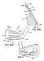
- An exemplary head for an iron 10is shown in FIG. 3 , and includes a face 12 , a sole 14 , a toe 16 , a heel 18 , a back 20 , a top line 22 , and a hosel 24 .
- the sole 14usually is cambered or otherwise shaped to minimize friction if the clubhead should contact the ground during a swing.
- the hosel 24receives the distal terminus of the shaft 26 of the golf club and is the means by which the head 10 is fastened to the shaft 26 .
- the angle of the hosel 24 to the rest of the head 10is the “lie” of the head 10 .
- the face 12 of an irontypically is “offset,” wherein offset is a distance from the front-most part of the hosel 24 to the front-most part, or leading edge, of the head 10 .
- the face 12typically has a series of score lines (grooves) 28 extending substantially horizontally across the face 12 .
- the particular depth and dimensions of the score lines 28are regulated by United States Golf Association (USGA) rules because the score lines contribute to the launch conditions of a ball struck off the face 12 .
- USGAUnited States Golf Association
- “Loft”is a measurement, in degrees, of the angle at which the face 12 of the clubhead 10 lies relative to a perfectly vertical plane.
- the faces of the clubheadsIn a typical set of irons from the “longest” iron to the “shortest” iron, the faces of the clubheads have progressively greater loft, which means that the faces are tilted progressively more from vertical.
- Loftaffects the launch angle, backspin, and velocity of a struck ball. Striking a ball with a short iron will typically result in the ball having a higher launch angle and greater backspin compared to a ball struck with a long iron. Consequently, the trajectory of a ball struck with a short iron will typically be higher and shorter than the trajectory of a ball struck with a long iron.
- the ironsare numbered to codify the loft; the higher the number, the greater the loft.
- Hitting the ball at any location on the face 12 of an iron (or any golf club)does not yield the same result.
- Every clubhas a “sweet spot” (a zone located roughly in a central region of the face) that represents the best hitting zone on the face 12 for maximizing the probability of the golfer achieving the best and most predictable shot using the particular club.
- the golferstrives to hit the ball inside the sweet spot to provide the greatest probability that the ball will have the intended trajectory.
- Providing a clubhead with a larger sweet spotgenerally makes the clubhead more “forgiving” of a golfer's variability in swinging the club and striking a ball with it, thus providing the golfer with a greater assurance of making the intended shot.
- An embodiment of a clubheadcomprises a forged front piece and a rear piece.
- the front pieceincludes the hosel, an iron-type face, a front heel portion, a front sole portion, a front toe portion, a front top-line portion, a respective interface surface facing substantially rearwardly of the face.
- the rear pieceincludes a rear heel portion, a rear sole portion, a rear toe portion, a rear top-line portion, and a respective interface surface facing the interface surface of the front piece.
- the interface surfaces of the front and rear piecesform a contact interface.
- a continuous weldextends circumferentially around the contact interface, thereby attaching the front and rear pieces together at the contact interface.
- the weldincludes a fusion zone that, at substantially all locations around the contact interface, extends into the contact interface in respective normal directions relative to the face.
- the weldbe formed by laser welding, which forms an unusually narrow fusion zone.
- Laser weldingalso facilitates preventing the weld from encroaching onto the face.
- the narrow circumferential weld(situated substantially in a plane behind the face) experiences mainly compressive forces generally in the direction of a normal to the face.
- the weldis particularly resistant to strong impact forces, compared to weaker face welds on certain conventional iron-type clubheads.
- Another advantage of laser weldingis that the top-line of the clubhead can be made thinner than conventionally.
- An exemplary thin thickness rangeis 4-7 mm, which provides good visual aesthetics and “feel” for many golfers.
- the front piecedesirably is forged of a high-strength steel such as a maraging steel, a maraging stainless steel, or a PH (precipitation-hardened) stainless steel.
- a C455 or 17-4 steelcan be used.
- the front and rear piecescan be made of different or similar materials, and the rear piece can be forged or cast.
- a distinct advantage of forging the front piece of a high-strength steelis that the face can be made significantly thinner than conventionally without compromising strength and while enhancing other parameters.
- the facecan have a thickness of less than 2.7 mm, or a thickness of less than 2.0 mm, or a thickness in the range of 1.6 to 2.0 mm.
- forgingcan also provide the reverse surface of the face with a desired thickness profile.
- the reverse surfacecan be formed with an inverted cone profile for enhancing the “sweet spot” of the face.
- the thinner face of the subject clubheadsfrees up discretionary mass that can be relocated, for example, onto the rear piece for desired positioning of the CG (center of gravity) of the clubhead, or for desired manipulation of the MOI (moment of inertia).
- the rear piececan be configured with weights or cartridges for redistributing the mass of the clubhead.
- a clubheadcomprises a front and a rear welded together.
- the frontincludes an iron-type face. Rearwardly of the face is the heel, sole, toe, and top-line of the clubhead.
- the rearis situated rearwardly of the heel, sole, toe, and top-line.
- the face of some embodimentshas a combination of a COR of at least 0.8 and a thickness, in a thinnest portion of the face, of no greater than 2.0 mm.
- the face of other embodimentshas a combination of a COR of at least 0.8 and an area of less than 3000 mm 2 .
- the frontdesirably is forged, as summarized above, and desirably includes the hosel.
- golfing ironseach comprising a shaft connected to a clubhead such as summarized above.
- An embodiment of such a methodcomprises forging a front piece having a face, a respective interface surface rearward of the face, and respective portions of a heel, a sole, a toe, and a top-line between the interface surface and the face. Also formed is a rear piece having a respective interface surface and respective portions of the heel, sole, toe, and top-line situated rearwardly of the interface surface. The interface surfaces are placed in contact and alignment with each other to form a contact interface. A continuous weld is formed that extends into and peripherally around the contact interface to attach the front and rear pieces together, the weld being, at substantially all locations thereon, substantially perpendicular to a normal to the face. As summarized above, the weld desirably is formed by laser welding.
- FIGS. 1(A)-1(C)are orthogonal views of an embodiment of a two-piece iron-type clubhead, as described herein and in the parent case, U.S. patent application Ser. No. 11/073,158 (published as U.S. Patent Application Publication No. US 2006/0199661). See FIGS. 1A-1C, respectively, in the parent case.
- the rear piece 54 shown in FIGS. 1(B) and 1(C)is called a “central weight” back.
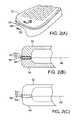
- FIG. 2(A)is a perspective view of a portion of the blade of an embodiment that has been laser-welded around the circumference (top-line, heel, sole, toe) of the contact interface of a rear piece fitted to a front piece.
- FIG. 2(B)is an enlargement of a partial section along the lines B-B in FIG. 2(A) .
- FIG. 2(C)is a further enlargement of the partial section shown in FIG. 2(B) .
- FIG. 2(D)is a substantially plan view of a clubhead, showing the path of laser welding around the circumference of the contact interface.
- FIG. 3is a perspective view of relevant features of a conventional iron-type clubhead, including a portion of the shaft. This figure is similar to FIG. 3 in the parent case.
- FIG. 4is a plan view of the rear of an embodiment of the front piece, including an exemplary sweet spot and showing an exemplary configuration of the interface surface (hatched).
- FIG. 5(A)is a front view of an embodiment of a finished iron-type clubhead.
- FIG. 5(B)is a sectional view along the lines B-B in FIG. 5(A) .
- FIG. 6is a rear view of an embodiment in which the rear piece 54 ′ is called a “toe-heel weight” back.
- Iron-type clubheads discussed belowhave traditionally small faces (generally in the range of 2950-3000 mm 2 ). They also have faces that are made of high-strength steel, and that are substantially thinner (e.g., 2.00 mm or less thickness at the center of the sweet spot on the face) than conventional iron-type clubheads.
- the subject clubheadshave a narrower top-line (e.g., 4.0 to 6.0 mm) a higher COR (e.g., 0.80 up to a USGA limit of about 0.83) than conventional irons.
- the CORis measured by utilizing a test ball speed of 160 feet per second.
- Various embodiments of the subject clubheadscomprise a front piece and a rear piece.
- the front pieceincludes the face, the hosel, and front portions of the top-line, toe, sole, and heel.
- the rear pieceincludes the back and rear portions of the top-line, toe, sole, and heel.
- the front pieceis forged, desirably of maraging steel, maraging stainless steel, or precipitation-hardened (PH) stainless steel.
- Forgingprovides the front piece, including the face, with very high strength, which allows the face to be made thinner than in conventional iron-type clubheads.
- the rear pieceis made of steel or stainless steel, forged or cast, and includes corresponding rear portions of the top-line, toe, sole, and heel. The rear piece can be made of the same material as the front piece.
- the weldis a laser weld.
- the weldis essentially a butt weld that, when made by a laser, includes a narrow and deep fusion zone (FZ) and very narrow heat-affected zones (HAZs) flanking the fusion zone.
- FZnarrow and deep fusion zone
- HZsvery narrow heat-affected zones
- the faces of the subject clubheadsare weld-free, with the FZs and HAZs being fully away from the face area.
- the narrow FZ and HAZ achieved by laser weldingalso allow the top-line to be made thinner (e.g., 4-6 mm) than a conventional thick top-line.
- the thin top-lineis aesthetically pleasing to many golfers. Even with a thinner face, the subject iron-type clubhead retains uncompromised strength and durability.
- laser weldingis advantageous for making the subject clubheads because laser welding concentrates more energy at the weld site than conventional welding techniques such as TIG welding. Laser welding also produces a more localized melt, less material interdiffusion, and reduced material fatigue during subsequent use.
- FIGS. 1(A)-1(C)General aspects of a first representative embodiment of a clubhead 50 are shown in FIGS. 1(A)-1(C) .
- the clubhead 50comprises a front piece 52 and a rear piece 54 .
- the front piece 52includes the hosel 56 and the face 58 .
- the face 58is surrounded by respective front portions of the heel 60 F, toe 62 F, sole 64 F, and top-line 66 F.
- To the rear of these respective portionsis a rearward-facing interface surface 72 , extending 360° circumferentially around the front piece 52 , configured to engage a corresponding forward-facing interface surface 74 on the rear piece 54 .
- the interface surface 72is approximately parallel to the plane of the face 58 .
- the rear piece 54includes the back 68 as well as respective rear portions of the heel 60 R, toe 62 R, sole 64 R, and top-line 66 R. Frontward of these respective portions is the interface surface 74 extending 360° circumferentially around the rear piece 54 . As shown in FIG. 1(C) (dashed line), the interface surfaces 72 , 74 fit together and form a “contact interface” that is bonded together by laser welding.
- the front piece 52 in many embodimentsis forged, desirably of maraging steel, maraging stainless steel, or precipitation-hardened (PH) stainless steel.
- maraging steelsin which the word “maraging” is a contraction of “martensitic” and “aging”) have high strength, toughness, and malleability. Being low in carbon, they derive their strength from precipitation of inter-metallic substances other than carbon.
- the principal alloying elementis nickel (usually 15 to nearly 30%). Other alloying elements producing inter-metallic precipitates in these steels include cobalt, molybdenum, and titanium.
- An example maraging steelcontains 18% nickel. Maraging stainless steels have less nickel than maraging steels but include significant chromium to inhibit rust.
- the chromiumaugments hardenability despite the reduced nickel content, which ensures the steel can transform to martensite when appropriately heat-treated.
- An example maraging stainless steelis C455.
- Example precipitation-hardened (PH) stainless steelsare 17-4, 15-5, and 17-7. Applicants believe that the subject clubheads are the first in the art in which at least the front pieces are forged of these materials.
- Forgingis performed by hot press forging using a progressive series of dies.
- Forging temperatureis in the plastic-deformation range of 900-1200° C., depending upon the alloy.
- the front pieces 52are subjected to an appropriate heat-treatment.
- 17-4 PH stainless steel forgingsare heat-treated by 1040° C. for 90 minutes, solution-quenched; C455 stainless steel forgings are solution heat-treated at 830° C. for 90 minutes, then quenched.
- example materials for making the rear piece 54are carbon steel (e.g., 1020, 1030, or 1040 carbon steel), chrome-molybdenum steel (e.g., 4140 Cr—Mo steel), Ni—Cr—Mo steel (e.g., 8620 Ni—Cr—Mo steel), austenitic stainless steel (e.g., 304, N50, or N60 stainless steel), ferritic stainless steel (e.g., 430 stainless steel), or martensitic stainless steel (e.g., 410 stainless steel).
- the weldmentwill be of dissimilar materials, but this is not a problem, especially with a laser weldment.
- the rear piece 54can include one or more features such as cartridges, weighting elements, and/or inserts or applied bodies as used for CG placement, vibration control or damping, acoustic control or damping, COR manipulation, or the like.
- weighting elementsmass-altering pins or cartridges
- the rear surface of the face of the front piececan include, for example, a “damping badge” or the like for visually aesthetic reasons and/or for manipulation of “feel.”
- planar interface surfaces 72 , 74are finish-machined as required to ensure they will form a good contact interface.
- the hole in the hosel 56 for the shaftcan be bored at this time.
- the interface surfaces 72 , 74desirably are planar for ease of finish machining and fitting together. Planar surfaces fit together well without significant intervening gap(s), but the two pieces 52 , 54 must be aligned with each other for welding.
- planar interface surfaces 72 , 74desirably include any of various alignment aids such as edges, lips, pins, nubbins, male-female detents, or the like that mutually engage whenever the interface surfaces are brought into contact with each other.
- the interface surfaces 72 , 74can have more complex topography, so long as the topographies are complementary to each other.
- Non-planar interface surfaces 72 , 74can be configured such that they are self-aligning, in which event alignment aids may not be necessary.
- the pieces 52 , 54are held together as an assembly using a clamp or fixture to ensure substantially no gap between the interface surfaces 72 , 74 .
- the clamp or fixturecan be configured to align the two pieces 52 , 54 without having to provide the pieces with alignment aids.
- FIG. 4A rear view of an exemplary front piece 52 is shown in FIG. 4 , depicting the top-line 66 F, heel 60 F, sole 64 F, toe 62 F, and interface surface 72 .
- the interface surface 72varies in radial width (hatched area) around its circumference (in the plane of the page). For example, in this embodiment, the radial width is greatest in the region of the hosel 56 and least along the top line 66 F and sole 64 F.
- the profile of radial widthdenotes that the interface surface 72 has an inside edge 90 . Regions of the interface-surface plane (plane of the page) that are inboard of the inside edge 90 are not part of the interface surface but rather are below the plane.
- the complementary interface surface 74 on the rear piece 54(not shown) has a radial-width profile that is a mirror image of the radial-width profile of the depicted interface surface 72 .
- the inside edge 90 of the depicted embodimentincludes projections 92 a , 92 b , 92 c , 92 d that serve as alignment aids for aligning the rear piece 54 to the front piece 52 .
- the projections 92 a - 92 dextend above the plane of the page and collectively fit just inside the inside edge of the interface surface 74 of the rear piece 54 .
- a single continuous projection extending fully around the circumference of the inside edge 90can be used.
- the projections 92 a - 92 dcan be replaced by multiple pins projecting above the plane of the page and that collectively fit just inside the inside edge of the interface surface 74 .
- multiple pinscan be located on the interface surface 72 and that fit into complementary holes in the interface surface 74 .
- multiple convex domescan be provided on the interface surface 72 that engage respective concave depressions on the interface surface 74 . It will be understood that, in these and other alternative embodiments, the projecting alignment aids can be located on the rear piece 54 rather than the front piece 52 .
- the depicted sweet spot 100is an ellipse (of which the major axis is nearly horizontal), including a central zone 100 a and a surrounding ridge 100 b .
- the rear surface 102has a nominal thickness (extending to the face 58 ) of 1.80 mm
- the ridge 100 bhas a thickness of 2.00 mm
- the central zone 100 ahas a thickness of 2.00 mm.
- the thicknesstapers back to 1.80 mm.
- Other thickness profilesare also possible in the range of 1.6 to less than 2.7 mm.
- the thickness profilescan be achieved during forging of the front piece 52 .
- a 0.5 mm to 1.0 mm machine stock platecan be added to the face 58 to increase tolerance control. After forging the face 58 can be slightly milled and engraved with scorelines. It is remarkable that such thin structures are achievable by forging, especially since conventional forged iron-type clubheads have face thicknesses of greater than 2.7 mm.
- a key advantage of being able to forge such a thin face 58is the consequential freeing up of discretionary mass (up to approximately 20 g) that can be placed elsewhere in the clubhead (particularly in the rear piece 54 ) for manipulation of the MOI and CG location.
- the particular profile of the sweet spot 100 described aboveis an example of so-called “inverted cone” configuration.
- Inverted-cone configurationsare discussed in, for example, U.S. Pat. Nos. 6,800,038; 6,824,475; 6,904,663; and 6,997,820, all incorporated herein by reference.
- weldingdesirably begins near the hosel where the radial width of the interface surfaces 72 , 74 is greatest ( FIG. 4 ). Welding progresses in a continuous manner around the contact interface 86 . At each location the “weld axis” 88 is normal to the surface. The speed at which the laser can be moved relative to the surface is desirably adjustable within the range of 40 to 80 cm/min.
- the welddesirably penetrates substantially fully (90% or more) into the radial width of the contact interface.
- Minimum useful penetrationis about 1 mm, but can be greater, depending on the radial width of the contact interface at the location being welded.
- the radial widthchanges around the circumference of the contact interface (see hatched region in FIG. 4 ), ranging from 1.4 mm (e.g., top-line) to 4.0 mm (near the hosel).
- the weld depthis in the range of approximately 1.25 mm to 3.60 mm.
- the surficial width of the fusion zoneis about 2 mm, and the fusion zone tends to become narrower with increasing depth.
- Weldingis not performed at a constant power or speed.
- the output power of the laser and the progression rate of the laser around the circumferenceare controllably adjusted as required to apply more power for a longer time in regions where the radial width is greatest (requiring the “deepest” weld) and to apply less power for less time in regions where the radial width is least (requiring the “shallowest” weld).
- FIGS. 2(A)-2(C)A schematic cross-section of one location on the laser weldment is shown in FIGS. 2(A)-2(C) .
- FIG. 2(A)shows a portion of the rear piece 54 , a portion of the front piece 52 , a portion of the contact interface 86 , and a portion of the weld zone 80 extending along the perimeter of the contact interface.
- the weld zone 80includes a narrow fusion zone (FZ) 82 flanked by extremely narrow heat-affected zones (HAZs) 84 .
- the FZ 82 and HAZs 84tend to be wider at the surface and are progressively narrower with increasing depth of the weld. In any event, the width of the weld zone 80 is much less than would be achieved by conventional welding methods such as TIG welding.
- the respective weld axes 88extend substantially perpendicularly to the direction of a load (ball-impact force) that would be applied to the face 58 during use.
- all the weld axes 88are in the plane of the contact interface 86 but with different orientation so as to be perpendicular to their respective locations on the periphery.
- No portion of the weldmentis located on the face 58 .
- welds made in the face of a conventional clubheadare nearly parallel to the impact force and thus experience significant tensile and shear forces.
- the face of the subject iron-type clubheadis substantially stronger than the face of a conventional welded iron-type clubhead. Consequently, the face 58 can be made thinner (e.g., 1.6-2.0 mm), as described above, than the face of a conventional iron-type clubhead without sacrificing required strength and durability.
- the laser weldmentgenerally has a narrower FZ 82 compared to a TIG weldment, for example, the clubhead can be configured with a narrower top-line (e.g., 4-7 mm) than a conventional iron-type clubhead.
- top-lineEven with the narrowest top-line, the weld zone 80 does not encroach upon the face 58 , so the top-line can be as narrow as practicable while still satisfying this criterion.
- a thin top-lineprovides a “classic” blade look to the iron, which many golfers prefer from the standpoint of visual aesthetics and/or “feel.”
- Another advantage to being able to form a high-strength but thinner face 58 exhibiting higher COR than conventionallyis the option of not having to form undercuts around the interface surfaces 72 , 74 , particularly along the top line. This is another factor allowing the top-line to be narrower than conventionally.
- the clubheadsare subjected to a heat treatment for, inter alia, aging.
- This post-weld heat treatmentis generally at 480-540° C. for four hours.
- the clubheadsare also finish-machined as required (generally grinding and polishing) to smooth and topologically blend the surface of the weldment into the contour of the clubhead. Polishing produces an excellent surface finish on which the weldment is invisible. Finish machining desirably is followed by passivation.
- a region (usually within the length range of 0.25 to 1.0 inch) of the hosel 56can be subjected to a local induction treatment (e.g., 800° C. for 3-10 seconds) to facilitate adjustment of the hosel-lie angle. Induction is immediately followed by rapid cool in air. Experience has shown that the lie-angle of the hosel has greater than 9 degrees of adjustability using this method.
- a local induction treatmente.g. 800° C. for 3-10 seconds
- Platingmay be performed to produce a surficial “plating” layer that protects against corrosion and is strong, durable, relatively inert, and aesthetically pleasing.
- Exemplary materials for forming a surficial plating layerare Cr, Ni, and Cu.
- Exemplary techniques for forming the surficial plating layerare electrode plating, electroless plating, physical vapor deposition (PVD), chemical vapor deposition (CVD), ion plating (IP), and ion-beam-enhanced diffusion (IBED).
- a plating sublayer(intermediate layer) be applied to the clubhead before applying the surficial plating layer in order to enhance adhesion of the surficial plating layer to the clubhead. This is because most plating layers are brittle and may crack under stress. Exemplary materials for use in forming the plating sublayer are soft nickel, soft copper, and oxides. The plating sublayer is applied in a conventional manner such as any of the methods listed above for forming the surficial plating layer.
- a clubhead as generally described aboveis made into a golf club by attaching a suitable shaft to the hosel (see FIG. 3 ).
- a suitable shaftto the hosel (see FIG. 3 ).
- Various conventional methods for attaching a shaft to a hoselare known in the art.
- various types of shaftsare known and available, including non-metallic shafts.
- a gripis attached to the shaft.
- the rear piece 54 shown in the embodiment of FIGS. 1(B) and 1(C)is exemplary only, and is called a “central weight” back in which more mass is present in the vicinity of the midline of the back.
- Another embodimentis shown in FIG. 6 in which the rear piece 54 ′ is called a “toe-heel weight” back, in which more mass is present in the vicinity of the heel and toe of the back than in the vicinity of the midline.
- iron-type clubheadshaving at least the following advantages: (a) made of two pieces, a front piece and a rear piece, the front piece including the hosel and face; (b) face can be small (2950-3000 mm 2 ); (c) the front piece desirably is forged of a high-strength steel alloy, which allows the face to be made thin (e.g., 1.6-2.0 mm); (d) the face can be formed with a patterned thickness distribution (e.g., a variable thickness sweet spot); (e) the pieces are welded together along a contact interface that avoids forming any of the weld on the face, producing a strong and durable face despite its thinness; (f) welding desirably is by laser welding, which allows the top-line to be thin (less than 7 mm); (g) making the face thinner frees up discretionary mass for placement elsewhere on the clubhead, such as in the toe, heel, or lower back region, to lower the CG of the clubhead further than conventionally
Landscapes
- Health & Medical Sciences (AREA)
- General Health & Medical Sciences (AREA)
- Physical Education & Sports Medicine (AREA)
- Golf Clubs (AREA)
Abstract
Description
| TABLE 1 | |||||||
| Club- | Face | Face | Face | Face Def. | Hosel | ||
| head | Thickness | Flatness | Hardness | COR | Wt | 3000 shot | Bend |
| 1 | 1.86 mm | <0.1 | 44.5 HRC | 0.803 | 242.8 g | ||
| 2 | 1.87 mm | <0.1 | 45.0 HRC | 0.801 | 243.0 g | ||
| 3 | 1.93 mm | <0.1 | 45.0 HRC | −4.5° | |||
| 4 | 1.86 mm | <0.1 | 0.08 | ||||
| 5 | 1.83 mm | <0.1 | 0.06 | ||||
The “Face Def.” is persistent face deflection after 3000 “shots” of a golf ball were directed at the face. Ball velocity was 46 m/s. Face-deflection data are in mm. Note that the specification was a deflection≦0.2 mm, so the clubheads exhibited excellent durability in this regard. “HRC” is Rockwell hardness “C” scale.
| TABLE 2 | |||
| Delta 1: | −8.56 mm | ||
| Delta 2: | 34.88 mm | ||
| Delta 3: | 65.94 mm | ||
| z-up: | 18.4 mm | ||
The “delta” values are coordinate-conversion numbers. The “z-up” dimension is the vertical coordinate of the CG. Hence, in the clubhead of this example, the CG is lower than conventionally.
| TABLE 3 | |||||
| Sample # | Material | Yield (MPa) | Tensile (MPa) | Elongation | Modulus |
| 1 | 455 | 1325.5 | 1365.5 | 11.9% | 182.8 GPa |
| 2 | 455 | 1353.6 | 1382.8 | 10% | 195.9 GPa |
| 3 | 455 | 1369 | 1406.2 | 10.5% | 198.6 GPa |
| TABLE 4 | ||||
| Element | Concentration | Specification | ||
| C | 0.05 | <0.05 | ||
| Mn | 0.36 | <0.5 | ||
| P | 0.018 | <0.04 | ||
| S | 0.002 | <0.03 | ||
| Si | 0.41 | <0.5 | ||
| Cu | 2.1 | 1.5-2.5 | ||
| Cr | 11.99 | 11.00-12.50 | ||
| Ni | 7.78 | 7.5-9.5 | ||
| Mo | 0.59 | <0.5 | ||
| Ti | 0.92 | 0.8-1.4 | ||
| Al | 0.11 | |||
| Fe | Balance | Balance | ||
Claims (12)
Priority Applications (1)
| Application Number | Priority Date | Filing Date | Title |
|---|---|---|---|
| US12/332,210US8858364B2 (en) | 2005-03-04 | 2008-12-10 | Welded iron-type clubhead with thin high-cor face |
Applications Claiming Priority (2)
| Application Number | Priority Date | Filing Date | Title |
|---|---|---|---|
| US11/073,158US7491136B2 (en) | 2005-03-04 | 2005-03-04 | Low-density FeAlMn alloy golf-club heads and golf clubs comprising same |
| US12/332,210US8858364B2 (en) | 2005-03-04 | 2008-12-10 | Welded iron-type clubhead with thin high-cor face |
Related Parent Applications (1)
| Application Number | Title | Priority Date | Filing Date |
|---|---|---|---|
| US11/073,158Continuation-In-PartUS7491136B2 (en) | 2005-03-04 | 2005-03-04 | Low-density FeAlMn alloy golf-club heads and golf clubs comprising same |
Publications (2)
| Publication Number | Publication Date |
|---|---|
| US20090149277A1 US20090149277A1 (en) | 2009-06-11 |
| US8858364B2true US8858364B2 (en) | 2014-10-14 |
Family
ID=40722231
Family Applications (1)
| Application Number | Title | Priority Date | Filing Date |
|---|---|---|---|
| US12/332,210Expired - LifetimeUS8858364B2 (en) | 2005-03-04 | 2008-12-10 | Welded iron-type clubhead with thin high-cor face |
Country Status (1)
| Country | Link |
|---|---|
| US (1) | US8858364B2 (en) |
Cited By (20)
| Publication number | Priority date | Publication date | Assignee | Title |
|---|---|---|---|---|
| USD777854S1 (en) | 2015-09-22 | 2017-01-31 | Karsten Manufacturing Corporation | Golf club head |
| US9884230B2 (en)* | 2013-03-15 | 2018-02-06 | Karsten Manufacturing Corporation | Golf club irons including backing material behind ball striking face |
| USD815704S1 (en) | 2016-10-14 | 2018-04-17 | Karsten Manufacturing Corporation | Golf club head |
| USD839371S1 (en) | 2017-09-15 | 2019-01-29 | Karsten Manufacturing Corporation | Golf club head |
| USD851718S1 (en) | 2018-03-05 | 2019-06-18 | Karsten Manufacturing Corporation | Golf club head |
| US10744377B1 (en)* | 2019-05-02 | 2020-08-18 | Chi-Shun CHUANG | Club head conducive to enhancement of resilience |
| US10881926B1 (en) | 2019-07-29 | 2021-01-05 | Taylor Made Golf Company, Inc. | Iron golf club head |
| US20210331045A1 (en)* | 2019-05-10 | 2021-10-28 | Taylor Made Golf Company, Inc. | Golf club |
| US20220111268A1 (en)* | 2019-05-10 | 2022-04-14 | Taylor Made Golf Company, Inc. | Clubheads for iron-type golf clubs |
| USD950658S1 (en) | 2020-07-14 | 2022-05-03 | Karsten Manufacturing Corporation | Golf club head |
| US11351429B2 (en)* | 2019-05-10 | 2022-06-07 | Taylor Made Golf Company, Inc. | Golf club |
| US11400351B2 (en)* | 2019-05-10 | 2022-08-02 | Taylor Made Golf Company, Inc. | Golf club |
| US11413510B2 (en)* | 2019-05-10 | 2022-08-16 | Taylor Made Golf Company, Inc. | Golf club |
| US11517797B2 (en) | 2010-03-16 | 2022-12-06 | Karsten Manufacturing Corporation | Iron-type golf club head or other ball striking device |
| US20230017457A1 (en)* | 2021-07-12 | 2023-01-19 | Sumitomo Rubber Industries, Ltd. | Golf club head |
| US20230101631A1 (en)* | 2021-09-24 | 2023-03-30 | Acushnet Company | Multi-material golf club head |
| US11992735B1 (en) | 2016-12-29 | 2024-05-28 | Taylor Made Golf Company, Inc. | Golf club head |
| US12097413B2 (en) | 2016-12-29 | 2024-09-24 | Taylor Made Golf Company, Inc. | Golf club head |
| US12172058B2 (en) | 2016-12-29 | 2024-12-24 | Taylor Made Golf Company, Inc. | Golf club head |
| US12186635B2 (en) | 2022-06-06 | 2025-01-07 | Karsten Manufacturing Corporation | Iron with mass pad |
Families Citing this family (45)
| Publication number | Priority date | Publication date | Assignee | Title |
|---|---|---|---|---|
| US8657700B2 (en) | 2007-07-25 | 2014-02-25 | Karsten Manufacturing Corporation | Club head sets with varying characteristics and related methods |
| US9079080B2 (en) | 2007-07-25 | 2015-07-14 | Karsten Manufacturing Corporation | Club head sets with varying characteristics and related methods |
| US8753230B2 (en) | 2007-07-25 | 2014-06-17 | Karsten Manufacturing Corporation | Club head sets with varying characteristics |
| US8690710B2 (en) | 2007-07-25 | 2014-04-08 | Karsten Manufacturing Corporation | Club head sets with varying characteristics and related methods |
| US9623296B2 (en) | 2007-07-25 | 2017-04-18 | Karsten Manufacturing Corporation | Club head sets with varying characteristics and related methods |
| US10434389B2 (en)* | 2009-06-11 | 2019-10-08 | Karsten Manufacturing Corporation | Golf club weight attachment mechanisms and related methods |
| USD607073S1 (en) | 2009-08-17 | 2009-12-29 | Karsten Manufacturing Corporation | Golf club head |
| USD621893S1 (en) | 2010-03-17 | 2010-08-17 | Karsten Manufacturing Corporation | Golf club head |
| USD621894S1 (en) | 2010-03-17 | 2010-08-17 | Karsten Manufacturing Corporation | Golf club head |
| USD627410S1 (en) | 2010-05-05 | 2010-11-16 | Karsten Manufacturing Corporation | Golf club head |
| USD635627S1 (en)* | 2010-06-29 | 2011-04-05 | Karsten Manufacturing Corporation | Golf club head |
| US20120028727A1 (en) | 2010-07-27 | 2012-02-02 | Cobra Golf Incorporated | Progressive set of golf club heads |
| US8475293B2 (en) | 2010-09-13 | 2013-07-02 | Acushnet Company | Iron golf club head with improved performance |
| USD643896S1 (en) | 2011-01-10 | 2011-08-23 | Karsten Manufacturing Corporation | Golf club head |
| USD643491S1 (en)* | 2011-01-18 | 2011-08-16 | Karsten Manufacturing Corporation | Golf club head |
| USD647582S1 (en) | 2011-03-15 | 2011-10-25 | Karsten Manufacturing Corporation | Golf club head |
| USD654547S1 (en) | 2011-08-11 | 2012-02-21 | Karstern Manufacturing Corporation | Golf club head |
| USD672417S1 (en) | 2012-06-21 | 2012-12-11 | Karsten Manufacturing Corporation | Golf club head |
| USD670775S1 (en) | 2012-06-22 | 2012-11-13 | Karsten Manufacturing Corporation | Golf club head |
| USD680603S1 (en) | 2012-12-19 | 2013-04-23 | Karsten Manufacturing Corporation | Golf club head |
| USD681143S1 (en) | 2012-12-19 | 2013-04-30 | Karsten Manufacturing Corporation | Golf club head |
| USD708688S1 (en) | 2013-05-16 | 2014-07-08 | Karsten Manufacturing Corporation | Golf club head |
| US9937395B2 (en) | 2013-11-12 | 2018-04-10 | Taylor Made Golf Company, Inc. | Golf club |
| US9492722B2 (en)* | 2013-11-12 | 2016-11-15 | Taylor Made Golf Company, Inc. | Golf club |
| USD720413S1 (en) | 2014-05-28 | 2014-12-30 | Karsten Manufacturing Corporation | Golf club head |
| USD716883S1 (en) | 2014-05-29 | 2014-11-04 | Karsten Manufacturing Corporation | Golf club head |
| US20160067558A1 (en)* | 2014-09-04 | 2016-03-10 | Dunlop Sports Company Limited | Article with metallic strip and method of making same |
| USD754269S1 (en) | 2014-09-05 | 2016-04-19 | Karsten Manufacturing Corporation | Golf club head |
| USD754806S1 (en) | 2015-01-05 | 2016-04-26 | Karsten Manufacturing Corporation | Golf club head |
| USD755316S1 (en) | 2015-01-09 | 2016-05-03 | Karsten Manufacturing Corporation | Badge for a golf club head |
| USD810215S1 (en) | 2016-03-25 | 2018-02-13 | Karsten Manufacturing Corporation | Golf club head |
| USD791892S1 (en) | 2016-03-25 | 2017-07-11 | Karsten Manufacturing Corporation | Golf club head |
| USD805146S1 (en) | 2016-03-25 | 2017-12-12 | Karsten Manufacturing Corporation | Golf club head |
| USD786990S1 (en)* | 2016-04-01 | 2017-05-16 | Callaway Golf Company | Golf club head |
| USD835734S1 (en) | 2017-08-24 | 2018-12-11 | Karsten Manufacturing Corporation | Golf club head |
| USD839370S1 (en) | 2017-09-15 | 2019-01-29 | Karsten Manufacturing Corporation | Golf club head |
| US11235212B2 (en) | 2018-02-26 | 2022-02-01 | Karsten Manufacturing Corporation | Multi-material iron golf club head |
| EP4374937B1 (en)* | 2018-02-26 | 2025-10-15 | Karsten Manufacturing Corporation | Multi-material iron golf club head |
| USD859547S1 (en) | 2018-04-17 | 2019-09-10 | Karsten Manufacturing Corporation | Golf club head |
| USD888172S1 (en) | 2018-09-26 | 2020-06-23 | Karsten Manufacturing Corporation | Golf club head |
| USD902333S1 (en) | 2019-04-01 | 2020-11-17 | Karsten Manufacturing Corporation | Golf club head |
| USD914815S1 (en) | 2019-04-01 | 2021-03-30 | Karsten Manufacturing Corporation | Golf club head |
| JP7669711B2 (en)* | 2021-02-05 | 2025-04-30 | 住友ゴム工業株式会社 | Golf Club Head |
| USD994810S1 (en) | 2021-09-23 | 2023-08-08 | Karsten Manufacturing Corporation | Golf club head |
| USD1039634S1 (en) | 2022-11-16 | 2024-08-20 | Karsten Manufacturing Corporation | Golf club head |
Citations (56)
| Publication number | Priority date | Publication date | Assignee | Title |
|---|---|---|---|---|
| US2931098A (en) | 1956-01-26 | 1960-04-05 | Nat Die Casting Company | Method of making a golf club head |
| US3193384A (en) | 1957-07-02 | 1965-07-06 | Langley Alloys Ltd | Iron aluminium alloys |
| US3652093A (en)* | 1970-07-20 | 1972-03-28 | John Reuter Jr Inc | Golf putter head with hollow toe and heel portions |
| US4314863A (en) | 1979-10-31 | 1982-02-09 | Fansteel Inc. | Stainless steel castings |
| US4968357A (en) | 1989-01-27 | 1990-11-06 | National Science Council | Hot-rolled alloy steel plate and the method of making |
| US5024437A (en)* | 1989-06-12 | 1991-06-18 | Gear Fit Golf, Inc. | Golf club head |
| US5089067A (en)* | 1991-01-24 | 1992-02-18 | Armco Inc. | Martensitic stainless steel |
| US5167733A (en) | 1992-02-06 | 1992-12-01 | Eastern Precision Casting Co., Ltd. | Method for manufacturing iron-manganese-aluminum alloy castings |
| US5184823A (en)* | 1989-11-22 | 1993-02-09 | Taylor Made Golf Company, Inc. | Golf club and golf club head |
| US5297803A (en)* | 1991-08-23 | 1994-03-29 | Karsten Manufacturing Corporation | Weighted cavity back golf club set |
| US5419560A (en) | 1994-03-15 | 1995-05-30 | Bamber; Jeffrey V. | Perimeter weighted golf clubs |
| US5429353A (en)* | 1993-07-30 | 1995-07-04 | Acushnet Company | Golf club irons and method of manufacture of iron sets |
| US5464216A (en)* | 1993-05-06 | 1995-11-07 | Yamaha Corporation | Golf club head |
| US5518240A (en)* | 1994-06-07 | 1996-05-21 | Igarashi; Lawrence Y. | Golf wood club head fabricating from cast head sections |
| US5536011A (en)* | 1994-06-21 | 1996-07-16 | Gutowski; Thaddeus | Perimeter-weighted golf club iron and method for making same |
| US5540437A (en)* | 1994-03-15 | 1996-07-30 | Bamber; Jeffrey V. | Perimeter weighted golf clubs |
| US5564705A (en)* | 1993-05-31 | 1996-10-15 | K.K. Endo Seisakusho | Golf club head with peripheral balance weights |
| US5584770A (en)* | 1995-02-06 | 1996-12-17 | Jensen; Morten A. | Perimeter weighted golf club head |
| US5683310A (en)* | 1996-07-02 | 1997-11-04 | Chen; Archer C. C. | Metal head of golf club |
| US5697855A (en) | 1994-12-16 | 1997-12-16 | Daiwa Seiko, Inc. | Golf club head |
| US5755627A (en)* | 1996-02-08 | 1998-05-26 | Mitsubishi Materials Corporation | Metal hollow golf club head with integrally formed neck |
| US5851157A (en)* | 1994-11-30 | 1998-12-22 | Bmga Co., Ltd. | Iron club for golf |
| US5871408A (en)* | 1997-06-23 | 1999-02-16 | Chen; Archer C. C. | Method for fusing a ball-striking plate with a golf club head case |
| US6015354A (en)* | 1998-03-05 | 2000-01-18 | Ahn; Stephen C. | Golf club with adjustable total weight, center of gravity and balance |
| US6083118A (en)* | 1997-07-30 | 2000-07-04 | Joseph Sery | Golf club head and method of manufacture |
| US6149534A (en)* | 1998-11-02 | 2000-11-21 | Taylor Made Golf Company, Inc. | Bi-metallic golf club head with single plane interface |
| US6247636B1 (en)* | 1999-02-16 | 2001-06-19 | Donald J. C. Sun | Hollow golf club head and method for manufacture |
| US6309309B1 (en) | 1997-05-09 | 2001-10-30 | Taylor Made Golf Company, Inc | Oversized iron-type golf club |
| US20010055996A1 (en)* | 2000-05-17 | 2001-12-27 | Mototaka Iwata | Iron golf club |
| US20020082118A1 (en)* | 2000-11-07 | 2002-06-27 | Mototaka Iwata | Golf club |
| US6458045B1 (en)* | 2001-02-20 | 2002-10-01 | Archer C. C. Chen | Golf club head |
| US6506129B2 (en)* | 2001-02-21 | 2003-01-14 | Archer C. C. Chen | Golf club head capable of enlarging flexible area of ball-hitting face thereof |
| US6520868B2 (en) | 2001-03-09 | 2003-02-18 | Archer C. C. Chen | Golf club head of steel alloy |
| US20030082067A1 (en) | 2001-10-25 | 2003-05-01 | Chih-Yeh Chao | Low-density iron based alloy for a golf club |
| US6617050B2 (en) | 2001-10-19 | 2003-09-09 | O-Ta Precision Casting Co., Ltd. | Low density and high ductility alloy steel for a golf club head |
| US20030176231A1 (en)* | 2002-03-14 | 2003-09-18 | Bridgestone Sports Co., Ltd. | Golf club head and golf club set |
| US20030176232A1 (en)* | 2002-03-14 | 2003-09-18 | Bridgestone Sports Co., Ltd. | Golf club set |
| US6685577B1 (en) | 1995-12-04 | 2004-02-03 | David M. Scruggs | Golf club made of a bulk-solidifying amorphous metal |
| US20040023730A1 (en)* | 2002-07-31 | 2004-02-05 | Masao Nagai | Utility iron golf club with weighting element |
| US6739983B2 (en) | 1999-11-01 | 2004-05-25 | Callaway Golf Company | Golf club head with customizable center of gravity |
| US6743114B2 (en) | 2002-04-25 | 2004-06-01 | Acushnet Company | Set of golf club irons |
| US6743118B1 (en) | 2002-11-18 | 2004-06-01 | Callaway Golf Company | Golf club head |
| US6743120B1 (en)* | 2003-02-13 | 2004-06-01 | Archer C. C. Chen | Iron golf club head |
| US20040171434A1 (en) | 2003-02-27 | 2004-09-02 | Roger Cleveland Golf Co., Inc. | Golf club head of ductile or gray iron |
| US6793591B2 (en)* | 2002-10-25 | 2004-09-21 | K. K. Endo Seisakusho | Golf club and method of producing the same |
| US20040192465A1 (en) | 2001-06-11 | 2004-09-30 | Taylor Made Golf Company, Inc. | Method for making a golf club face |
| US6811496B2 (en) | 2000-12-01 | 2004-11-02 | Taylor Made Golf Company, Inc. | Golf club head |
| US7008331B2 (en)* | 2004-03-04 | 2006-03-07 | Chen Archer C C | Iron golf club head |
| US7083525B2 (en) | 2001-10-30 | 2006-08-01 | Roger Cleveland Golf Company, Inc. | Golf club head with insert |
| US7121958B2 (en)* | 2003-06-27 | 2006-10-17 | Advanced International Multitech Co., Ltd. | Positioning structure in a golf club head |
| US7169057B2 (en)* | 2004-01-28 | 2007-01-30 | Macgregor Golf Company | Hollow and metal iron golf club heads |
| US7258628B2 (en)* | 2005-01-10 | 2007-08-21 | Nelson Precision Casting Co., Ltd. | Intensified structure for connecting a golf club head body with a striking plate |
| US7371188B2 (en)* | 2005-05-03 | 2008-05-13 | Nelson Precision Casting Co., Ltd. | Golf club head having a connecting structure for a high degree of flexibility |
| US7491136B2 (en)* | 2005-03-04 | 2009-02-17 | Taylor Made Golf Company, Inc. | Low-density FeAlMn alloy golf-club heads and golf clubs comprising same |
| US7530902B2 (en)* | 2006-06-12 | 2009-05-12 | Sri Sports Limited | Iron-type golf club head |
| US7892106B2 (en)* | 2008-03-28 | 2011-02-22 | Sri Sports Limited | Iron-type golf club head and golf club set |
Family Cites Families (1)
| Publication number | Priority date | Publication date | Assignee | Title |
|---|---|---|---|---|
| US652868A (en)* | 1899-04-28 | 1900-07-03 | John Howard White | Apparatus for making paper tubes. |
- 2008
- 2008-12-10USUS12/332,210patent/US8858364B2/ennot_activeExpired - Lifetime
Patent Citations (59)
| Publication number | Priority date | Publication date | Assignee | Title |
|---|---|---|---|---|
| US2931098A (en) | 1956-01-26 | 1960-04-05 | Nat Die Casting Company | Method of making a golf club head |
| US3193384A (en) | 1957-07-02 | 1965-07-06 | Langley Alloys Ltd | Iron aluminium alloys |
| US3652093A (en)* | 1970-07-20 | 1972-03-28 | John Reuter Jr Inc | Golf putter head with hollow toe and heel portions |
| US4314863A (en) | 1979-10-31 | 1982-02-09 | Fansteel Inc. | Stainless steel castings |
| US4968357A (en) | 1989-01-27 | 1990-11-06 | National Science Council | Hot-rolled alloy steel plate and the method of making |
| US5024437A (en)* | 1989-06-12 | 1991-06-18 | Gear Fit Golf, Inc. | Golf club head |
| US5184823A (en)* | 1989-11-22 | 1993-02-09 | Taylor Made Golf Company, Inc. | Golf club and golf club head |
| US5089067A (en)* | 1991-01-24 | 1992-02-18 | Armco Inc. | Martensitic stainless steel |
| US5297803A (en)* | 1991-08-23 | 1994-03-29 | Karsten Manufacturing Corporation | Weighted cavity back golf club set |
| US5423534A (en)* | 1991-08-23 | 1995-06-13 | Karsten Manufacturing Corporation | Iron-type golf club |
| US5167733A (en) | 1992-02-06 | 1992-12-01 | Eastern Precision Casting Co., Ltd. | Method for manufacturing iron-manganese-aluminum alloy castings |
| US5464216A (en)* | 1993-05-06 | 1995-11-07 | Yamaha Corporation | Golf club head |
| US5564705A (en)* | 1993-05-31 | 1996-10-15 | K.K. Endo Seisakusho | Golf club head with peripheral balance weights |
| US5429353A (en)* | 1993-07-30 | 1995-07-04 | Acushnet Company | Golf club irons and method of manufacture of iron sets |
| US5540437A (en)* | 1994-03-15 | 1996-07-30 | Bamber; Jeffrey V. | Perimeter weighted golf clubs |
| US5419560A (en) | 1994-03-15 | 1995-05-30 | Bamber; Jeffrey V. | Perimeter weighted golf clubs |
| US5518240A (en)* | 1994-06-07 | 1996-05-21 | Igarashi; Lawrence Y. | Golf wood club head fabricating from cast head sections |
| US5536011A (en)* | 1994-06-21 | 1996-07-16 | Gutowski; Thaddeus | Perimeter-weighted golf club iron and method for making same |
| US5851157A (en)* | 1994-11-30 | 1998-12-22 | Bmga Co., Ltd. | Iron club for golf |
| US5697855A (en) | 1994-12-16 | 1997-12-16 | Daiwa Seiko, Inc. | Golf club head |
| US5584770A (en)* | 1995-02-06 | 1996-12-17 | Jensen; Morten A. | Perimeter weighted golf club head |
| US6685577B1 (en) | 1995-12-04 | 2004-02-03 | David M. Scruggs | Golf club made of a bulk-solidifying amorphous metal |
| US5755627A (en)* | 1996-02-08 | 1998-05-26 | Mitsubishi Materials Corporation | Metal hollow golf club head with integrally formed neck |
| US5683310A (en)* | 1996-07-02 | 1997-11-04 | Chen; Archer C. C. | Metal head of golf club |
| US6309309B1 (en) | 1997-05-09 | 2001-10-30 | Taylor Made Golf Company, Inc | Oversized iron-type golf club |
| US5871408A (en)* | 1997-06-23 | 1999-02-16 | Chen; Archer C. C. | Method for fusing a ball-striking plate with a golf club head case |
| US6083118A (en)* | 1997-07-30 | 2000-07-04 | Joseph Sery | Golf club head and method of manufacture |
| US6015354A (en)* | 1998-03-05 | 2000-01-18 | Ahn; Stephen C. | Golf club with adjustable total weight, center of gravity and balance |
| US6149534A (en)* | 1998-11-02 | 2000-11-21 | Taylor Made Golf Company, Inc. | Bi-metallic golf club head with single plane interface |
| US6247636B1 (en)* | 1999-02-16 | 2001-06-19 | Donald J. C. Sun | Hollow golf club head and method for manufacture |
| US6739983B2 (en) | 1999-11-01 | 2004-05-25 | Callaway Golf Company | Golf club head with customizable center of gravity |
| US20010055996A1 (en)* | 2000-05-17 | 2001-12-27 | Mototaka Iwata | Iron golf club |
| US20020082118A1 (en)* | 2000-11-07 | 2002-06-27 | Mototaka Iwata | Golf club |
| US6811496B2 (en) | 2000-12-01 | 2004-11-02 | Taylor Made Golf Company, Inc. | Golf club head |
| US6458045B1 (en)* | 2001-02-20 | 2002-10-01 | Archer C. C. Chen | Golf club head |
| US6506129B2 (en)* | 2001-02-21 | 2003-01-14 | Archer C. C. Chen | Golf club head capable of enlarging flexible area of ball-hitting face thereof |
| US6520868B2 (en) | 2001-03-09 | 2003-02-18 | Archer C. C. Chen | Golf club head of steel alloy |
| US20040192465A1 (en) | 2001-06-11 | 2004-09-30 | Taylor Made Golf Company, Inc. | Method for making a golf club face |
| US6617050B2 (en) | 2001-10-19 | 2003-09-09 | O-Ta Precision Casting Co., Ltd. | Low density and high ductility alloy steel for a golf club head |
| US20030082067A1 (en) | 2001-10-25 | 2003-05-01 | Chih-Yeh Chao | Low-density iron based alloy for a golf club |
| US7083525B2 (en) | 2001-10-30 | 2006-08-01 | Roger Cleveland Golf Company, Inc. | Golf club head with insert |
| US20030176232A1 (en)* | 2002-03-14 | 2003-09-18 | Bridgestone Sports Co., Ltd. | Golf club set |
| US20030176231A1 (en)* | 2002-03-14 | 2003-09-18 | Bridgestone Sports Co., Ltd. | Golf club head and golf club set |
| US6984180B2 (en)* | 2002-03-14 | 2006-01-10 | Bridgestone Sports Co., Ltd. | Golf club head and golf club set |
| US6743114B2 (en) | 2002-04-25 | 2004-06-01 | Acushnet Company | Set of golf club irons |
| US20040023730A1 (en)* | 2002-07-31 | 2004-02-05 | Masao Nagai | Utility iron golf club with weighting element |
| US7126339B2 (en)* | 2002-07-31 | 2006-10-24 | Mizuno Corporation | Utility iron golf club with weighting element |
| US6793591B2 (en)* | 2002-10-25 | 2004-09-21 | K. K. Endo Seisakusho | Golf club and method of producing the same |
| US6743118B1 (en) | 2002-11-18 | 2004-06-01 | Callaway Golf Company | Golf club head |
| US6743120B1 (en)* | 2003-02-13 | 2004-06-01 | Archer C. C. Chen | Iron golf club head |
| US20040171434A1 (en) | 2003-02-27 | 2004-09-02 | Roger Cleveland Golf Co., Inc. | Golf club head of ductile or gray iron |
| US7121958B2 (en)* | 2003-06-27 | 2006-10-17 | Advanced International Multitech Co., Ltd. | Positioning structure in a golf club head |
| US7169057B2 (en)* | 2004-01-28 | 2007-01-30 | Macgregor Golf Company | Hollow and metal iron golf club heads |
| US7008331B2 (en)* | 2004-03-04 | 2006-03-07 | Chen Archer C C | Iron golf club head |
| US7258628B2 (en)* | 2005-01-10 | 2007-08-21 | Nelson Precision Casting Co., Ltd. | Intensified structure for connecting a golf club head body with a striking plate |
| US7491136B2 (en)* | 2005-03-04 | 2009-02-17 | Taylor Made Golf Company, Inc. | Low-density FeAlMn alloy golf-club heads and golf clubs comprising same |
| US7371188B2 (en)* | 2005-05-03 | 2008-05-13 | Nelson Precision Casting Co., Ltd. | Golf club head having a connecting structure for a high degree of flexibility |
| US7530902B2 (en)* | 2006-06-12 | 2009-05-12 | Sri Sports Limited | Iron-type golf club head |
| US7892106B2 (en)* | 2008-03-28 | 2011-02-22 | Sri Sports Limited | Iron-type golf club head and golf club set |
Non-Patent Citations (1)
| Title |
|---|
| Callister, Jr., William D., Materials Science and Engineering: An Introduction, 4th Edition. New York: John Wiley & Sons, Inc., copyright 1997, p. 775. |
Cited By (38)
| Publication number | Priority date | Publication date | Assignee | Title |
|---|---|---|---|---|
| US11517797B2 (en) | 2010-03-16 | 2022-12-06 | Karsten Manufacturing Corporation | Iron-type golf club head or other ball striking device |
| US12097412B2 (en) | 2010-03-16 | 2024-09-24 | Karsten Manufacturing Corporation | Iron-type golf club head or other ball striking device |
| US9884230B2 (en)* | 2013-03-15 | 2018-02-06 | Karsten Manufacturing Corporation | Golf club irons including backing material behind ball striking face |
| US10293222B2 (en) | 2013-03-15 | 2019-05-21 | Karsten Manufacturing Corporation | Golf club irons including backing material behind ball striking face |
| US10639526B2 (en) | 2013-03-15 | 2020-05-05 | Karsten Manufacturing Corporation | Golf club irons including backing material behind ball striking face |
| USD777854S1 (en) | 2015-09-22 | 2017-01-31 | Karsten Manufacturing Corporation | Golf club head |
| USD815704S1 (en) | 2016-10-14 | 2018-04-17 | Karsten Manufacturing Corporation | Golf club head |
| US12251606B2 (en) | 2016-12-29 | 2025-03-18 | Taylor Made Golf Company, Inc. | Golf club head |
| US12172058B2 (en) | 2016-12-29 | 2024-12-24 | Taylor Made Golf Company, Inc. | Golf club head |
| US12109463B2 (en) | 2016-12-29 | 2024-10-08 | Taylor Made Golf Company, Inc. | Golf club head |
| US12097414B2 (en) | 2016-12-29 | 2024-09-24 | Taylor Made Golf Company, Inc. | Golf club head |
| US12097413B2 (en) | 2016-12-29 | 2024-09-24 | Taylor Made Golf Company, Inc. | Golf club head |
| US11992735B1 (en) | 2016-12-29 | 2024-05-28 | Taylor Made Golf Company, Inc. | Golf club head |
| USD839371S1 (en) | 2017-09-15 | 2019-01-29 | Karsten Manufacturing Corporation | Golf club head |
| USD851718S1 (en) | 2018-03-05 | 2019-06-18 | Karsten Manufacturing Corporation | Golf club head |
| US10744377B1 (en)* | 2019-05-02 | 2020-08-18 | Chi-Shun CHUANG | Club head conducive to enhancement of resilience |
| US20210331045A1 (en)* | 2019-05-10 | 2021-10-28 | Taylor Made Golf Company, Inc. | Golf club |
| US11351429B2 (en)* | 2019-05-10 | 2022-06-07 | Taylor Made Golf Company, Inc. | Golf club |
| US20220111268A1 (en)* | 2019-05-10 | 2022-04-14 | Taylor Made Golf Company, Inc. | Clubheads for iron-type golf clubs |
| US20230028968A1 (en)* | 2019-05-10 | 2023-01-26 | Taylor Made Golf Company, Inc. | Golf club |
| US20230052836A1 (en)* | 2019-05-10 | 2023-02-16 | Taylor Made Golf Company, Inc. | Golf club |
| US11400351B2 (en)* | 2019-05-10 | 2022-08-02 | Taylor Made Golf Company, Inc. | Golf club |
| US11413510B2 (en)* | 2019-05-10 | 2022-08-16 | Taylor Made Golf Company, Inc. | Golf club |
| US11883724B2 (en) | 2019-05-10 | 2024-01-30 | Taylor Made Golf Company, Inc. | Golf club |
| US11918874B2 (en) | 2019-05-10 | 2024-03-05 | Taylor Made Golf Company, Inc. | Golf club |
| US12053679B2 (en)* | 2019-05-10 | 2024-08-06 | Taylor Made Golf Company, Inc. | Golf club |
| US11951365B2 (en)* | 2019-05-10 | 2024-04-09 | Taylor Made Golf Company, Inc. | Golf club |
| US11458374B2 (en)* | 2019-05-10 | 2022-10-04 | Taylor Made Golf Company, Inc. | Golf club |
| US20240207701A1 (en)* | 2019-05-10 | 2024-06-27 | Taylor Made Golf Company, Inc. | Golf club |
| US11497972B2 (en) | 2019-07-29 | 2022-11-15 | Taylor Made Golf Company, Inc. | Iron golf club head |
| US12186634B2 (en) | 2019-07-29 | 2025-01-07 | Taylor Made Golf Company, Inc. | Iron golf club head |
| US10881926B1 (en) | 2019-07-29 | 2021-01-05 | Taylor Made Golf Company, Inc. | Iron golf club head |
| USD950658S1 (en) | 2020-07-14 | 2022-05-03 | Karsten Manufacturing Corporation | Golf club head |
| US11925840B2 (en)* | 2021-07-12 | 2024-03-12 | Sumitomo Rubber Industries, Ltd. | Golf club head |
| US20230017457A1 (en)* | 2021-07-12 | 2023-01-19 | Sumitomo Rubber Industries, Ltd. | Golf club head |
| US11839797B2 (en)* | 2021-09-24 | 2023-12-12 | Acushnet Company | Multi-material golf club head |
| US20230101631A1 (en)* | 2021-09-24 | 2023-03-30 | Acushnet Company | Multi-material golf club head |
| US12186635B2 (en) | 2022-06-06 | 2025-01-07 | Karsten Manufacturing Corporation | Iron with mass pad |
Also Published As
| Publication number | Publication date |
|---|---|
| US20090149277A1 (en) | 2009-06-11 |
Similar Documents
| Publication | Publication Date | Title |
|---|---|---|
| US8858364B2 (en) | Welded iron-type clubhead with thin high-cor face | |
| US8932150B2 (en) | Golf club head | |
| USRE50275E1 (en) | Golf club head | |
| US6916253B2 (en) | Golf club | |
| US7559853B2 (en) | Golf club head and method for manufacturing the same | |
| US7153222B2 (en) | Forged iron-type golf clubs | |
| US8128510B2 (en) | Golf club head | |
| US11890516B2 (en) | Iron-type golf club head | |
| US7491136B2 (en) | Low-density FeAlMn alloy golf-club heads and golf clubs comprising same | |
| US7846039B2 (en) | Golf club head | |
| US7857713B2 (en) | Wood-type golf club head | |
| US8133133B2 (en) | Forged iron-type golf clubs | |
| US8434671B1 (en) | Manufacturing method of a forged golf club head | |
| US7621824B2 (en) | Golf club head | |
| US7819759B2 (en) | Golf club head | |
| US7166042B2 (en) | Forged iron-type golf clubs | |
| US20050037860A1 (en) | Forged iron-type golf clubs | |
| JP2007029710A (en) | Golf club head and method for manufacturing the same | |
| US20250041680A1 (en) | Damascus steel hitting surface on golf irons | |
| KR20250098953A (en) | Golf club head | |
| JP2022045056A (en) | Iron club head and its manufacturing method |
Legal Events
| Date | Code | Title | Description |
|---|---|---|---|
| AS | Assignment | Owner name:TAYLOR MADE GOLF COMPANY, INC., CALIFORNIA Free format text:ASSIGNMENT OF ASSIGNORS INTEREST;ASSIGNORS:DENG, XINHUI;CHAO, BING-LING;REEL/FRAME:021957/0841 Effective date:20081209 | |
| FEPP | Fee payment procedure | Free format text:PAYOR NUMBER ASSIGNED (ORIGINAL EVENT CODE: ASPN); ENTITY STATUS OF PATENT OWNER: LARGE ENTITY | |
| STCF | Information on status: patent grant | Free format text:PATENTED CASE | |
| AS | Assignment | Owner name:KPS CAPITAL FINANCE MANAGEMENT, LLC, AS COLLATERAL AGENT, NEW YORK Free format text:SECURITY INTEREST;ASSIGNOR:TAYLOR MADE GOLF COMPANY, INC.;REEL/FRAME:044207/0745 Effective date:20171002 Owner name:ADIDAS NORTH AMERICA, INC., AS COLLATERAL AGENT, OREGON Free format text:SECURITY INTEREST;ASSIGNOR:TAYLOR MADE GOLF COMPANY, INC.;REEL/FRAME:044206/0765 Effective date:20171002 Owner name:PNC BANK, NATIONAL ASSOCIATION, AS COLLATERAL AGENT, PENNSYLVANIA Free format text:SECURITY INTEREST;ASSIGNOR:TAYLOR MADE GOLF COMPANY, INC.;REEL/FRAME:044206/0712 Effective date:20171002 Owner name:KPS CAPITAL FINANCE MANAGEMENT, LLC, AS COLLATERAL Free format text:SECURITY INTEREST;ASSIGNOR:TAYLOR MADE GOLF COMPANY, INC.;REEL/FRAME:044207/0745 Effective date:20171002 Owner name:PNC BANK, NATIONAL ASSOCIATION, AS COLLATERAL AGEN Free format text:SECURITY INTEREST;ASSIGNOR:TAYLOR MADE GOLF COMPANY, INC.;REEL/FRAME:044206/0712 Effective date:20171002 Owner name:ADIDAS NORTH AMERICA, INC., AS COLLATERAL AGENT, O Free format text:SECURITY INTEREST;ASSIGNOR:TAYLOR MADE GOLF COMPANY, INC.;REEL/FRAME:044206/0765 Effective date:20171002 | |
| MAFP | Maintenance fee payment | Free format text:PAYMENT OF MAINTENANCE FEE, 4TH YEAR, LARGE ENTITY (ORIGINAL EVENT CODE: M1551) Year of fee payment:4 | |
| AS | Assignment | Owner name:TAYLOR MADE GOLF COMPANY, INC., CALIFORNIA Free format text:RELEASE BY SECURED PARTY;ASSIGNOR:ADIDAS NORTH AMERICA, INC.;REEL/FRAME:057453/0167 Effective date:20210802 Owner name:TAYLOR MADE GOLF COMPANY, INC., CALIFORNIA Free format text:RELEASE BY SECURED PARTY;ASSIGNOR:PNC BANK, NATIONAL ASSOCIATION;REEL/FRAME:057085/0314 Effective date:20210802 Owner name:TAYLOR MADE GOLF COMPANY, INC., CALIFORNIA Free format text:RELEASE BY SECURED PARTY;ASSIGNOR:KPS CAPITAL FINANCE MANAGEMENT, LLC;REEL/FRAME:057085/0262 Effective date:20210802 | |
| AS | Assignment | Owner name:KOOKMIN BANK, AS SECURITY AGENT, KOREA, REPUBLIC OF Free format text:NOTICE OF GRANT OF SECURITY INTEREST IN PATENTS;ASSIGNOR:TAYLOR MADE GOLF COMPANY, INC.;REEL/FRAME:057300/0058 Effective date:20210824 Owner name:KOOKMIN BANK, AS COLLATERAL AGENT, KOREA, REPUBLIC OF Free format text:NOTICE OF GRANT OF SECURITY INTEREST IN PATENTS;ASSIGNOR:TAYLOR MADE GOLF COMPANY, INC.;REEL/FRAME:057293/0207 Effective date:20210824 | |
| AS | Assignment | Owner name:BANK OF AMERICA, N.A., AS COLLATERAL AGENT, NEW YORK Free format text:NOTICE OF GRANT OF SECURITY INTEREST IN PATENTS;ASSIGNOR:TAYLOR MADE GOLF COMPANY, INC.;REEL/FRAME:058962/0415 Effective date:20220207 Owner name:JPMORGAN CHASE BANK, N.A., AS COLLATERAL AGENT, NEW YORK Free format text:NOTICE OF GRANT OF SECURITY INTEREST IN PATENTS;ASSIGNOR:TAYLOR MADE GOLF COMPANY, INC.;REEL/FRAME:058963/0671 Effective date:20220207 | |
| AS | Assignment | Owner name:TAYLOR MADE GOLF COMPANY, INC., CALIFORNIA Free format text:RELEASE OF SECURITY INTEREST IN PATENTS;ASSIGNOR:KOOKMIN BANK;REEL/FRAME:058983/0516 Effective date:20220208 Owner name:TAYLOR MADE GOLF COMPANY, INC., CALIFORNIA Free format text:RELEASE OF SECURITY INTEREST IN PATENTS;ASSIGNOR:KOOKMIN BANK;REEL/FRAME:058978/0211 Effective date:20220208 | |
| MAFP | Maintenance fee payment | Free format text:PAYMENT OF MAINTENANCE FEE, 8TH YEAR, LARGE ENTITY (ORIGINAL EVENT CODE: M1552); ENTITY STATUS OF PATENT OWNER: LARGE ENTITY Year of fee payment:8 |