US8856986B2 - Patient positioning support structure - Google Patents
Patient positioning support structureDownload PDFInfo
- Publication number
- US8856986B2 US8856986B2US13/902,487US201313902487AUS8856986B2US 8856986 B2US8856986 B2US 8856986B2US 201313902487 AUS201313902487 AUS 201313902487AUS 8856986 B2US8856986 B2US 8856986B2
- Authority
- US
- United States
- Prior art keywords
- support
- pivot
- patient support
- surgical table
- patient
- Prior art date
- Legal status (The legal status is an assumption and is not a legal conclusion. Google has not performed a legal analysis and makes no representation as to the accuracy of the status listed.)
- Expired - Lifetime
Links
- 238000013519translationMethods0.000claimsdescription9
- 238000006073displacement reactionMethods0.000claims11
- 230000008878couplingEffects0.000claims5
- 238000010168coupling processMethods0.000claims5
- 238000005859coupling reactionMethods0.000claims5
- 238000005452bendingMethods0.000abstractdescription4
- 238000001356surgical procedureMethods0.000description20
- 238000003384imaging methodMethods0.000description19
- 230000036961partial effectEffects0.000description13
- 238000000034methodMethods0.000description12
- 230000007246mechanismEffects0.000description11
- 230000000712assemblyEffects0.000description10
- 238000000429assemblyMethods0.000description10
- 238000005516engineering processMethods0.000description4
- 230000002441reversible effectEffects0.000description4
- 208000027418Wounds and injuryDiseases0.000description3
- 239000007943implantSubstances0.000description3
- 235000004443Ricinus communisNutrition0.000description2
- 240000000528Ricinus communisSpecies0.000description2
- 230000008901benefitEffects0.000description2
- 230000005484gravityEffects0.000description2
- 210000003041ligamentAnatomy0.000description2
- 230000000399orthopedic effectEffects0.000description2
- 238000012546transferMethods0.000description2
- 206010002091AnaesthesiaDiseases0.000description1
- 208000001132OsteoporosisDiseases0.000description1
- 230000037005anaesthesiaEffects0.000description1
- 238000004873anchoringMethods0.000description1
- 238000013459approachMethods0.000description1
- 230000009286beneficial effectEffects0.000description1
- 238000011109contaminationMethods0.000description1
- 230000006378damageEffects0.000description1
- 230000003247decreasing effectEffects0.000description1
- 238000003745diagnosisMethods0.000description1
- 230000009977dual effectEffects0.000description1
- 230000004927fusionEffects0.000description1
- 208000014674injuryDiseases0.000description1
- 238000003780insertionMethods0.000description1
- 230000037431insertionEffects0.000description1
- 238000009434installationMethods0.000description1
- 230000010354integrationEffects0.000description1
- 230000000670limiting effectEffects0.000description1
- 238000004321preservationMethods0.000description1
- 238000003825pressingMethods0.000description1
- 230000002829reductive effectEffects0.000description1
- 239000003381stabilizerSubstances0.000description1
- 239000000725suspensionSubstances0.000description1
- 230000001360synchronised effectEffects0.000description1
- 238000012360testing methodMethods0.000description1
- 238000004804windingMethods0.000description1
Images


Classifications
- A—HUMAN NECESSITIES
- A61—MEDICAL OR VETERINARY SCIENCE; HYGIENE
- A61G—TRANSPORT, PERSONAL CONVEYANCES, OR ACCOMMODATION SPECIALLY ADAPTED FOR PATIENTS OR DISABLED PERSONS; OPERATING TABLES OR CHAIRS; CHAIRS FOR DENTISTRY; FUNERAL DEVICES
- A61G7/00—Beds specially adapted for nursing; Devices for lifting patients or disabled persons
- A61G7/002—Beds specially adapted for nursing; Devices for lifting patients or disabled persons having adjustable mattress frame
- A61G7/012—Beds specially adapted for nursing; Devices for lifting patients or disabled persons having adjustable mattress frame raising or lowering of the whole mattress frame
- A—HUMAN NECESSITIES
- A61—MEDICAL OR VETERINARY SCIENCE; HYGIENE
- A61G—TRANSPORT, PERSONAL CONVEYANCES, OR ACCOMMODATION SPECIALLY ADAPTED FOR PATIENTS OR DISABLED PERSONS; OPERATING TABLES OR CHAIRS; CHAIRS FOR DENTISTRY; FUNERAL DEVICES
- A61G13/00—Operating tables; Auxiliary appliances therefor
- A61G13/02—Adjustable operating tables; Controls therefor
- A61G13/08—Adjustable operating tables; Controls therefor the table being divided into different adjustable sections
- A—HUMAN NECESSITIES
- A61—MEDICAL OR VETERINARY SCIENCE; HYGIENE
- A61B—DIAGNOSIS; SURGERY; IDENTIFICATION
- A61B6/00—Apparatus or devices for radiation diagnosis; Apparatus or devices for radiation diagnosis combined with radiation therapy equipment
- A61B6/04—Positioning of patients; Tiltable beds or the like
- A61B6/0407—Supports, e.g. tables or beds, for the body or parts of the body
- A61B6/0421—Supports, e.g. tables or beds, for the body or parts of the body with immobilising means
- A—HUMAN NECESSITIES
- A61—MEDICAL OR VETERINARY SCIENCE; HYGIENE
- A61B—DIAGNOSIS; SURGERY; IDENTIFICATION
- A61B6/00—Apparatus or devices for radiation diagnosis; Apparatus or devices for radiation diagnosis combined with radiation therapy equipment
- A61B6/04—Positioning of patients; Tiltable beds or the like
- A61B6/0487—Motor-assisted positioning
- A—HUMAN NECESSITIES
- A61—MEDICAL OR VETERINARY SCIENCE; HYGIENE
- A61G—TRANSPORT, PERSONAL CONVEYANCES, OR ACCOMMODATION SPECIALLY ADAPTED FOR PATIENTS OR DISABLED PERSONS; OPERATING TABLES OR CHAIRS; CHAIRS FOR DENTISTRY; FUNERAL DEVICES
- A61G13/00—Operating tables; Auxiliary appliances therefor
- A61G13/0018—Physician's examining tables
- A—HUMAN NECESSITIES
- A61—MEDICAL OR VETERINARY SCIENCE; HYGIENE
- A61G—TRANSPORT, PERSONAL CONVEYANCES, OR ACCOMMODATION SPECIALLY ADAPTED FOR PATIENTS OR DISABLED PERSONS; OPERATING TABLES OR CHAIRS; CHAIRS FOR DENTISTRY; FUNERAL DEVICES
- A61G13/00—Operating tables; Auxiliary appliances therefor
- A61G13/0036—Orthopaedic operating tables
- A61G13/0054—Orthopaedic operating tables specially adapted for back or spinal surgeries
- A—HUMAN NECESSITIES
- A61—MEDICAL OR VETERINARY SCIENCE; HYGIENE
- A61G—TRANSPORT, PERSONAL CONVEYANCES, OR ACCOMMODATION SPECIALLY ADAPTED FOR PATIENTS OR DISABLED PERSONS; OPERATING TABLES OR CHAIRS; CHAIRS FOR DENTISTRY; FUNERAL DEVICES
- A61G13/00—Operating tables; Auxiliary appliances therefor
- A61G13/02—Adjustable operating tables; Controls therefor
- A61G13/04—Adjustable operating tables; Controls therefor tiltable around transverse or longitudinal axis
- A—HUMAN NECESSITIES
- A61—MEDICAL OR VETERINARY SCIENCE; HYGIENE
- A61G—TRANSPORT, PERSONAL CONVEYANCES, OR ACCOMMODATION SPECIALLY ADAPTED FOR PATIENTS OR DISABLED PERSONS; OPERATING TABLES OR CHAIRS; CHAIRS FOR DENTISTRY; FUNERAL DEVICES
- A61G13/00—Operating tables; Auxiliary appliances therefor
- A61G13/02—Adjustable operating tables; Controls therefor
- A61G13/06—Adjustable operating tables; Controls therefor raising or lowering of the whole table surface
- A—HUMAN NECESSITIES
- A61—MEDICAL OR VETERINARY SCIENCE; HYGIENE
- A61G—TRANSPORT, PERSONAL CONVEYANCES, OR ACCOMMODATION SPECIALLY ADAPTED FOR PATIENTS OR DISABLED PERSONS; OPERATING TABLES OR CHAIRS; CHAIRS FOR DENTISTRY; FUNERAL DEVICES
- A61G7/00—Beds specially adapted for nursing; Devices for lifting patients or disabled persons
- A61G7/001—Beds specially adapted for nursing; Devices for lifting patients or disabled persons with means for turning-over the patient
- A—HUMAN NECESSITIES
- A61—MEDICAL OR VETERINARY SCIENCE; HYGIENE
- A61G—TRANSPORT, PERSONAL CONVEYANCES, OR ACCOMMODATION SPECIALLY ADAPTED FOR PATIENTS OR DISABLED PERSONS; OPERATING TABLES OR CHAIRS; CHAIRS FOR DENTISTRY; FUNERAL DEVICES
- A61G7/00—Beds specially adapted for nursing; Devices for lifting patients or disabled persons
- A61G7/002—Beds specially adapted for nursing; Devices for lifting patients or disabled persons having adjustable mattress frame
- A61G7/008—Beds specially adapted for nursing; Devices for lifting patients or disabled persons having adjustable mattress frame tiltable around longitudinal axis, e.g. for rolling
- A61G2013/0054—
Definitions
- the present inventionis directed to structure for use in maintaining a patient in a desired position during examination and treatment, including medical procedures such as imaging and surgery and in particular to such a structure that allows a surgeon to selectively position the patient for convenient access to the surgery site and providing for manipulation of the patient during surgery including the tilting, pivoting, angulating or bending of a trunk of a patient in a supine, prone or lateral position.
- Imaging techniques and technologiesthroughout the course of patient examination, diagnosis and treatment.
- minimally invasive surgical techniquessuch as percutaneous insertion of spinal implants, involve small incisions that are guided by continuous or repeated intra-operative imaging. These images can be processed using computer software programs that produce three dimensional images for reference by the surgeon during the course of the procedure.
- the patient support surfaceis not radiolucent or compatible with the imaging technologies, it may be necessary to interrupt the surgery periodically in order to remove the patient to a separate surface for imaging followed by transfer back to the operating support surface for resumption of the surgical procedure.
- Such patient transfers for imaging purposesmay be avoided by employing radiolucent and other imaging compatible systems.
- the patient support systemshould also be constructed to permit unobstructed movement of the imaging equipment and other surgical equipment around, over and under the patient throughout the course of the surgical procedure without contamination of the sterile field.
- the patient support systembe constructed to provide optimum access to the surgical field by the surgery team.
- Some proceduresrequire positioning of portions of the patient's body in different ways at different times during the procedure.
- Some procedures, for example, spinal surgeryinvolve access through more than one surgical site or field.
- the patient support surfacesshould be adjustable and capable of providing support in different planes for different parts of the patient's body as well as different positions or alignments for a given part of the body.
- the support surfaceshould be adjustable to provide support in separate planes and in different alignments for the head and upper trunk portion of the patient's body, the lower trunk and pelvic portion of the body as well as each of the limbs independently.
- Certain types of surgerymay require that the patient or a part of the patient be repositioned during the procedure while in some cases maintaining the sterile field.
- surgeryis directed toward motion preservation procedures, such as by installation of artificial joints, spinal ligaments and total disc prostheses, for example, the surgeon must be able to manipulate certain joints while supporting selected portions of the patient's body during surgery in order to facilitate the procedure. It is also desirable to be able to test the range of motion of the surgically repaired or stabilized joint and to observe the gliding movement of the reconstructed articulating prosthetic surfaces or the tension and flexibility of artificial ligaments and other types of dynamic stabilizers before the wound is closed.
- Such manipulationcan be used, for example, to verify the correct positioning and function of an implanted prosthetic disc or joint replacement during a surgical procedure.
- manipulationdiscloses binding, sub-optimal position or even crushing of the adjacent vertebrae, for example, as may occur with osteoporosis, the prosthesis can be removed and the adjacent vertebrae fused while the patient remains anesthetized. Damage which might otherwise have resulted from a “trial” use of the implant post-operatively will be avoided, along with the need for a second round of anesthesia and surgery to remove the implant or prosthesis and perform the revision, fusion or corrective surgery.
- a patient support surfacethat can be rotated, articulated and angulated so that the patient can be moved from a prone to a supine position or from a prone to a 90° position and whereby intra-operative extension and flexion of at least a portion of the spinal column can be achieved.
- the patient support surfacemust also be capable of easy, selective adjustment without necessitating removal of the patient or causing substantial interruption of the procedure.
- the patient support surfaceshould also be capable of rotation about an axis in order to provide correct positioning of the patient and optimum accessibility for the surgeon as well as imaging equipment during such sequential procedures.
- Orthopedic proceduresmay also require the use of traction equipment such as cables, tongs, pulleys and weights.
- the patient support systemmust include structure for anchoring such equipment and it must provide adequate support to withstand unequal forces generated by traction against such equipment.
- Articulated robotic armsare increasingly employed to perform surgical techniques. These units are generally designed to move short distances and to perform very precise work. Reliance on the patient support structure to perform any necessary gross movement of the patient can be beneficial, especially if the movements are synchronized or coordinated. Such units require a surgical support surface capable of smoothly performing the multi-directional movements which would otherwise be performed by trained medical personnel. There is thus a need in this application as well for integration between the robotics technology and the patient positioning technology.
- While conventional operating tablesgenerally include structure that permits tilting or rotation of a patient support surface about a longitudinal axis, previous surgical support devices have attempted to address the need for access by providing a cantilevered patient support surface on one end.
- Such designstypically employ either a massive base to counterbalance the extended support member or a large overhead frame structure to provide support from above.
- the enlarged base members associated with such cantilever designsare problematic in that they may obstruct the movement of C-arm mobile fluoroscopic imaging devices.
- Surgical tables with overhead frame structuresare bulky and may require the use of dedicated operating rooms, since in some cases they cannot be moved easily out of the way. Neither of these designs is easily portable or storable.
- the present inventionis directed to a patient support system that permits adjustable positioning, repositioning and selectively lockable support of a patient's head and upper body, lower body and limbs in up to a plurality of individual planes while permitting tilting, rotation, angulation or bending and other manipulations as well as full and free access to the patient by medical personnel and equipment.
- the system of the inventionincludes at least one support end or column that is height adjustable.
- the illustrated embodimentincludes a pair of independently height-adjustable end support columns. The columns may be independent or connected to a horizontally length-adjustable base.
- One support column according to the inventionmay be coupled with a wall mount or other stationary support.
- a patient support structureis connected to and bridges substantially between the pair of end supports.
- the support structuremay be a frame or other patient support having at least first and second hingeable or pivotally connected portions, the first and second portions being selectively lockable in a first substantially planar orientation along a longitudinal axis of the support structure.
- the first and second portionsare also positionable and lockable in a plurality of angles with respect to one another, with each portion being movable to a position on either side of the first planar orientation.
- the patient support structureis capable of hinging or otherwise bending to form an angulation or break, either upwardly or downwardly when the support structure is in a substantially horizontal position and also when the support structure is in an inclined position due to one of the support columns raising one end of the structure higher than another end.
- a breakmay be from side-to-side when the support structure is rotated about a longitudinal axis thereof.
- angulation or breaking of the support structureis supported by a cable drive system (tension band suspension) that supports angulation using stationary end supports.
- a cable drive systemtension band suspension
- Other embodimentsinclude cantilevered systems with connected or unconnected movable or telescoping base supports.
- the first and second support structure portionsmay be in the form of frames, such as rectangular frames or other support structure that may be equipped with support pads for holding the patient, or other structure, such as imaging tops.
- the patient support structure and the support column or columnsare coupled with respective rotation, articulation or angulation adjustment structure for positioning the first support portion with respect to a first column or end support and with respect to the second support portion and the second support portion with respect to the second column or end support.
- Rotation adjustment structure in cooperation with pivoting and height adjustment structureprovide for the lockable positioning of the first and second patient support portions at a variety of selected positions and articulations with respect to the support columns including angulation coupled with Trendelenburg and reverse Trendelenburg configurations as well as providing for patient roll over in horizontal or tilted orientation. Lateral movement (toward and away from a surgeon) may also be provided by a bearing block feature.
- a pair of patient support structuresmay be mounted between end supports of the invention and then rotated in unison about a longitudinal axis to achieve 180° repositioning of a patient, from a prone to a supine position.
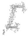
- FIG. 1is a perspective view of a patient support structure according to the invention.
- FIG. 2is an enlarged and partial side elevational view of a portion of the support structure of FIG. 2 .
- FIG. 3is an enlarged and partial top plan view of the support structure of 1 .
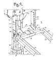
- FIG. 4is an enlarged and partial perspective view of a portion of the structure of FIG. 1 .
- FIG. 5is an enlarged and partial side elevational view of a portion of the structure of FIG. 1 .
- FIG. 6is an enlarged and partial perspective view of a portion of the structure of FIG. 1 .
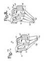
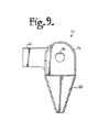
- FIG. 7is an enlarged and partial perspective view of a first hinge of the structure of FIG. 1 .
- FIG. 8is an enlarged and partial perspective view of a cooperating second hinge of the structure of FIG. 1 .
- FIG. 9is an enlarged and partial elevational view of the hinge of FIG. 7 .
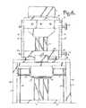
- FIG. 10is an enlarged and partial perspective view of an outer portion of the hinge of FIG. 7 with portions broken away to show the detail thereof.
- FIG. 11is an enlarged and partial perspective view of an inner portion of the hinge of FIG. 7 with portions broken away to show the detail thereof.
- FIG. 12is an enlarged and partial perspective view of a portion of the structure of FIG. 1 showing a cable drive motor and winch cylinders.
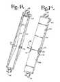
- FIG. 13is a partial perspective view of a patient support frame of the structure of FIG. 1 .
- FIG. 14is a partial perspective view of a patient imaging top for replacement with the patent support frame of FIG. 13 .
- FIG. 15is a reduced perspective view of the structure of FIG. 1 shown with an imaging top of FIG. 14 replacing the support frame of FIG. 13 and shown in a planar inclined position.
- FIG. 16is a perspective view of the structure of FIG. 15 shown in a planar tilted position.
- FIG. 17is a perspective view of the structure of FIG. 15 shown in a planar inclined and tilted position.
- FIG. 18is a side elevational view of the structure of FIG. 15 shown in a symmetrical upward breaking position.
- FIG. 19is a side elevational view of the structure of FIG. 15 shown in a first inclined and upward breaking position.
- FIG. 20is a side elevational view of the structure of FIG. 15 shown in a second inclined and upward breaking position.
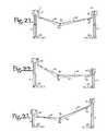
- FIG. 21is a side elevational view of the structure of FIG. 15 shown in a symmetrical downward breaking position.
- FIG. 22is a side elevational view of the structure of FIG. 15 shown in a first inclined and downward breaking position.
- FIG. 23is a side elevational view of the structure of FIG. 15 shown in a second inclined and downward breaking position.
- FIG. 24is an enlarged side elevational view of the structure of FIG. 1 shown in an upward breaking, inclined and tilted position.
- FIG. 25is a is a perspective view of a second embodiment of a patient support structure according to the invention.
- FIG. 26is a perspective view of the patient support structure of FIG. 25 shown tilted in an intermediate position during a rotation as would be used for a patient rollover.
- FIG. 27is a perspective view of the structure of FIG. 25 shown further tilted in a second intermediate position during rotation.
- FIG. 28is a perspective view of the structure of FIG. 25 shown after rotation to a final flipped position.
- FIG. 29is a front elevational view of a third embodiment of a patient support structure according to the invention.
- FIG. 30is a front elevational view of a fourth embodiment of a patient support structure according to the invention.
- FIG. 31is a perspective view of a fifth embodiment of a patient support structure according to the invention shown in a planar inclined position.
- FIG. 32is a perspective view of the structure of FIG. 31 shown in an inclined and upward breaking position.
- FIG. 33is a perspective view of the structure of FIG. 31 shown in a substantially symmetrical downward breaking position.
- FIGS. 1-12a patient positioning support structure according to the invention is generally designated by the reference numeral 1 and is depicted in FIGS. 1-12 .
- the structure 1includes first and second upright support piers or columns 3 and 4 which are illustrated as independent, stationary floor base support structures as shown in FIG. 1 or may be connected to one another by a non-telescoping base support as illustrated in the embodiment shown in FIGS. 25-28 .
- the base connectionplaces the columns in a selectively telescoping relationship.
- one of the support columnsmay be replaced by a conventional operating table support, or may even be a wall mount.
- the upright support column 3is connected to a first support assembly, generally 5
- the upright support column 4is connected to a second support assembly, generally 6 .
- the support assemblies 5 and 6uphold an elongate and angulatable or breaking patient holding or support structure, generally 10 and optionally, a removable patient support structure that will be described with respect to another embodiment of the invention.
- the illustrated support structure 10includes a first frame section 12 , a second frame section 14 with a transverse support cross bar 15 , and a pivot or hinge assembly, generally 16 .
- the pivot assemblyfurther includes a cable drive system including a dual winch 18 and cooperating cables 20 .
- the columns 3 and 4are supported by outwardly extending feet 22 that may or may not include spaced apart casters or wheels (not shown) each equipped with a floor-lock foot lever for lowering the feet 12 into a floor-engaging position as shown in FIG. 1 .
- the columns 3 and 4each include two or more telescoping lift arm segments 3 a , 3 b and 4 a , 4 b , respectively that permit the height of each of the columns 3 and 4 to be selectively increased and decreased in order to raise and lower all or a selected portion of the connected patient support structure 10 .
- the vertical supports 3 and 4may be constructed so that the column 3 has a greater mass than the support column 4 or vice versa in order to accommodate an uneven weight distribution of the human body. Such reduction in size at the foot end of the system 1 may be employed in some embodiments to facilitate the approach of personnel and equipment.
- Each of the support assemblies 5 and 6generally includes a rotation subassembly 26 and 26 ′ and an angulation subassembly 27 and 27 ′, respectively, that are interconnected as will be described in greater detail below and include associated power source and circuitry linked to a controller 29 ( FIG. 1 ) for cooperative and integrated actuation and operation.
- the rotational subassemblies 26 and 26 ′enable coordinated rotation of the patient support structure 10 about a longitudinal axis.
- the angulation subassemblies 27 and 27 ′enable the selective hinging or breaking of the support 10 by the hinge assembly 16 at desired levels and increments as well as selective tilting of the longitudinal axis of the frame portion 12 or 14 .
- the rotation subassembly or mechanism 26is shown in FIG. 5 and includes at least one motor housing 30 surmounting the support column 3 .
- a main rotational shaft 32extends from the motor housing 30 that turns a rotation structure 33 .
- the rotation structure 33in turn rotates the connected patient support 10 about a longitudinal axis as will be described in greater detail below.
- the motor housing 30contains a rotary electric motor or other actuator drivingly engaged with the shaft 32 .
- the rotation mechanism 26is operated by actuating the motor using a switch or other similar means.
- the rotation structure 33is fixed to the shaft 32 at a location spaced from the motor housing 30 and the support column 3 to provide clearance for rotation of the connected patient support structure 10 .
- the rotation structure 33is attached to a pair of translation posts or H-bar posts 40 disposed at either end of the rotation structure 33 .
- the posts 40are each attached to the structure 33 by a pin 42 , bolt, or other fixing structure.
- a plurality of cooperating apertures 44 formed in the posts 40provide passageway for a pivot pin 46 to extend therethrough.
- the pivot pin 46is receivable in each cooperating pair of apertures 44 allowing for selective placement of a translation connector 48 that is sized and shaped to be received between the pair of posts 40 and also receive the pivot pin 46 therethrough.
- the pin 46 and connector 48are thus positionable in an orientation transverse to the longitudinal extension of the support 10 at a variety of heights to be selected by the surgeon and readily changeable, even during surgery if necessary, to vary the height of the frame section 12 .
- the multiple location or height featureis also advantageous when more than one frame or patent structure is mounted in tandem as shown, for example in FIGS. 25-28 .
- the position of the frame or other structuremay be desirably changed to provide close proximity to an imaging top with a distance between a patient support and an imaging top being expandable or reduceable depending upon the size or other attributes of a patient and surgical or other requirements.
- the connector 48has a slot 50 for receiving the pivot pin 46 .
- the translation connector 48is in turn attached to a pivot connector 52 .
- the pivot connector 52includes first and second outwardly opening and opposed slots 54 and 56 .
- the first slot 54is sized and shaped for receiving the translation connector 48 and the second slot is sized and shaped for receiving an end connection 58 of the frame section 12 .
- the pivot connector 52further includes a through aperture or bore 60 running substantially perpendicular to the slot 54 and communicating therewith.
- the aperture 60is sized and shaped to receive a pivot pin 62 therethrough, allowing for some forward and rearward lateral movement of the attached frame end connection 58 and thus the frame section 12 , providing a degree of freedom and clearance needed for rotation the patient support about a longitudinal axis of a patient.
- the slot 56is sized and shaped to frictionally engage the frame end connection 58 , thus securely fixing the end connection 58 to the pivot connector 52 .
- the frame end connection 58is in turn fixed to each of elongate frame members 66 and 68 of the frame section 12 .
- the frame members 66 and 68are each hingedly connected to the hinge assembly 16 to be described in greater detail below. Pivoting of the translation connector 48 with respect to the pin 46 provides for selected articulation of the frame section 12 (that includes the end connection 58 and the frame members 66 and 68 ) and/or the entire support 10 with respect to the support pier or column 3 .
- the support assembly 6is substantially similar to the support assembly 5 with the exception that the rotation subassembly 26 ′ is passive and therefore does not include a motor.
- the support pier or column 4preferably includes a powered mechanism to provide selective height adjustment of the subassembly 26 ′.
- a rotation structure 33 ′is spaced from and freely rotatable with respect to the column 4 .
- the structure 33 ′includes a shaft (not shown) extending outwardly therefrom similar to the rotation shaft 32 , the shaft being rotatingly received in an aperture in the support column 4 .
- the rotation subassembly 26 ′ and the angulation subassembly 27otherwise include elements identical to or substantially similar to the elements of the subassemblies 26 and 27 .
- H-bar posts 40 ′, pin 42 ′, apertures 44 ′, pivot pin 46 ′, translation connector 48 ′, slot 50 ′, pivot connector 52 ′, end connector 58 ′ and pivot pin 62 ′are identical or substantially similar in form and cooperate with other elements identically or substantially similarly to what has been described previously herein with respective H-bar posts 40 , pin 42 , apertures 44 , pivot pin 46 , translation connector 48 , slot 50 , pivot connector 52 , end connector 58 and pivot pin 62 .
- the frame 14further includes frame members 66 ′ and 68 ′ that are each fixed to the end connector 58 ′.
- the frame members 66 ′ and 68 ′are pivotably or hingedly connected to respective frame members 66 and 68 by the hinge assembly 16 .
- the frame member 66is attached to the frame member 66 ′ by the hinge mechanism 70 and the frame member 68 is attached to the frame member 68 ′ by the hinge mechanism 72 .
- the hinge mechanism 70includes an outer member 76 and an inner member 78 .
- the outer member 76is fixed or may be integral with the elongate frame member 66
- the inner member 78is integral or otherwise fixed to the frame member 66 ′.
- the outer member 76further includes an extension 80 with a groove 82 for receiving and guiding the cable 20 .
- the extension 89tapers in a direction from the outer member interior 84 to the groove 82 .
- the extension 89is configured to cause a slight upward break or bend of the support 10 when the extension 89 comes into contact with the cable 20 at the groove 82 . In that way, when the cables 20 are reeled in to shorten the hypotenuse of the triangle formed by the cable, the section 12 and the section 14 , the sections 12 and 14 move toward one another, resulting in the upward break as illustrated, for example, in FIG. 18 .
- the downward break illustrated, for example, in FIG. 21is a result of lengthening the cable 20 distance and allowing gravity to drop the hinge 70 .
- the extension 89is shaped to extend slightly inwardly toward a longitudinal axis A of the support 10 , thereby guiding the cable 20 along a path within a periphery of the frame sections 12 and 14 when the extension 89 is in contact with the cable 20 when in a downward breaking configuration directed toward the cable with the cable 20 being received at the groove 82 .
- the sections 12 and 14may be positioned with respect to two end columns to always include a slight upward break or bend at the hinge or pivot between the sections 12 and 14 .
- the sections 12 and 14When the telescoping base is actuated to move the columns toward one another, the sections 12 and 14 would automatically further break upwardly and toward one another. Downward breaking would not be possible in such an embodiment as the maximum distance between the two end columns would still ensure a slight upward break or hinge between the sections 12 and 14 .
- Such an embodimentwould be acceptable for use because patient holding pads could be positioned on the frames 12 and 14 such that the patient would be in a substantially horizontal position even when there is a slight upward bend or break at the hinge between the sections 12 and 14 .
- the inner member 78is slidingly and rotatably receivable in an interior 84 of the outer member 76 .
- the outer memberhas a pair of pivot apertures 86 and the inner member has a pivot aperture 87 , the apertures cooperating to create a through bore for receiving a pivot pin 88 through both the inner and outer hinge members.
- the interior 84includes a curved partially cylindrical surface 89 for slidingly receiving a cooperating outer rounded and partially cylindrical surface 90 of the inner member 78 .
- the inner member 78further includes a downward breaking stop or projection 92 that limits a downward pivot (in a direction toward the cables 20 ) of the hinge 70 in the event the cables 20 should fail.
- the stop 92abuts against a surface 93 of the interior 84 .
- the stop 92limits the extent of rotation or hinging of the section 66 with respect to the section 66 ′ to about twenty-five degrees.
- Upward pivot(in a direction away from the cables 20 ) is limited by abutment of an inner planar surface 95 with a planar surface 96 of the hinge inner member 78 .
- the hinge mechanism 72is substantially a mirror image of the hinge mechanism 70 and therefore includes the following elements: a hinge outer member 76 ′, and inner member 78 ′, and extension 80 ′ with a groove 82 ′, and interior 84 ′ pivot apertures 86 ′ and 88 ′, a pivot pin 88 ′, a curved surface 89 ′, and outer surface 90 ′, a stop 92 ′, an abutment surface 93 ′, an inner planar surface 95 ′ and a planar surface 96 ′.
- hinge outer member 76is substantially similar in shape and function to the respective hinge outer member 76 , inner member 78 , extension 80 , groove 82 , interior 84 , pivot apertures 86 and 88 , pivot pin 88 , curved surface 89 , outer surface 90 , stop 92 , abutment surface 93 , inner planar surface 95 and planar surface 96 described herein with respect to the hinge 70 .
- hinge or pivot mechanismsmay be utilized in lieu of the hinge assembly 16 .
- the polyaxial joint 95 illustrated and described in Applicant's pending U.S. patent application Ser. No. 11/062,775 filed Feb. 22, 2005, and pending U.S. patent application Ser. No. 11/159,494 filed Jun. 23, 2005,may be incorporated into the patient support structure 10 at the break between the sections 12 and 14 . Both of these U.S. applications (Ser. Nos. 11/062,775 and 11/159,494) are hereby incorporated by reference herein.
- the cable drive system 18includes a rotary motor 98 cooperating with and driving by rotation a pair of winch cylinders 99 disposed on either side of the motor 98 .
- the motor 98 and cylinders 99are mounted to the end connector 58 ′ located near the support column 4 .
- Each cable 20is attached to one of the winch cylinders 99 at one end thereof and to the end connector 58 at the other end thereof.
- the cables 20are wound about the winch cylinders 99 an amount to provide enough tension in the cables 20 to maintain such a substantially planar orientation and configuration, with the hinge extensions 82 and 82 ′ being in contact with each of the cables 20 .
- the motor 98is preferably low speed and high torque for safely winding both of the cables 20 simultaneously about the cylinders 99 to draw the section 12 toward the section 14 to result in an upward breaking configuration with the hinges 70 and 72 disposed in spaced relation with the cables 20 and the hinges 70 and 72 .
- the motor 98may be reversed, reversing the direction of rotation of the winch cylinders 99 for slowly unwinding the cables 20 to a downward breaking configuration.
- gravitydraws the support sections 12 and 14 downward with the cables 20 being received in the grooves 82 and 82 ′ of the hinge extensions 80 and 80 ′.
- the hinges 70 and 72continue to lower pressing down upon the cables 20 .
- the frame sections 12 and 14are typically equipped with pads (not shown) or other patient holding structure. Furthermore, with respect to FIGS. 13 and 14 , the frame member sections 66 and 68 of section 12 and the frame member sections 66 ′ and 68 ′ of the section 14 may be replaced with substantially rectangular imaging tops or sections 100 and 101 ′ respectively. Each of the sections 100 and 101 ′ having elongate slots 101 formed therein to allow for attachment of the hinge mechanisms 70 and 72 in a manner identical or substantially similar to what has been described herein with respect to the frame sections 12 and 14 .
- FIGS. 15-17the imaging sections 100 and 100 ′ are illustrated, replacing the frame sections 12 and 14 of the embodiment disclosed in FIGS. 1-12 .
- FIGS. 15-17represent configurations in which the cable drive 18 is tensioned such that the sections 100 and 100 ′ are kept in a substantially coplanar configuration.
- FIG. 15illustrates a configuration in which the column 3 is telescoped upwardly with the frame sections hinging at the support assemblies 5 and 6 , resulting in an inclined position or configuration of the entire patient support.
- the section 100would preferably receive a patient's head. Therefore, FIG. 15 illustrates a reverse Trendelenburg position or orientation.
- FIG. 15illustrates a reverse Trendelenburg position or orientation.
- FIG. 16illustrates the sections 100 and 100 ′ again in a substantially common plane with both sections being rotated to a tilted position produced by a powered rotation of the rotation the sub assemblies 26 and passive rotation of the assembly 26 ′ with both columns 3 and 4 otherwise holding the sections 100 and 100 ′ at the same height.
- FIG. 17illustrates both tilting due to rotation of the assemblies 26 and 26 ′ and also a sloping or inclined position with the column 4 being extended vertically. Thus, FIG. 17 illustrates a Trendelenburg position or orientation with both the sections 100 and 100 ′ remaining in substantially the same plane.
- FIG. 18illustrates a symmetrical upward breaking configuration wherein the columns 3 and 4 are holding the respective support assemblies 5 and 6 at substantially the same height with the cables 20 being shortened by rotation of the winch motor to result in an upward break in the hinge assembly 16 .
- FIG. 19illustrates the column 3 being extended to a maximum height and the cables reeled to shorten a distance between the sections 100 and 100 ′.
- An example of such an upward break with reverse Trendelenburgwould be a head or column 3 height of 43 inches, a foot or column 4 height of 24 inches and a 35 degree upward break with zero degree roll.
- FIG. 20illustrates an upward breaking Trendelenburg with the column 4 being extended to a maximum height.
- FIG. 21illustrates a symmetrical downward breaking configuration wherein the columns 3 and 4 are holding the support assemblies 5 and 6 respectively, at the same height with the cables 20 being unwound or slackened to result in a downward break in the hinge assembly 16 , the hinges 70 and 72 contacting the cables 20 .
- FIG. 22illustrates a downward breaking reverse Trendelenburg with the column 3 being extended to a maximum height resulting in a patent's head end being at a maximum height.
- FIG. 23illustrates a downward breaking Trendelenburg with the column 4 being extended to a maximum height.
- FIG. 24illustrates the structure 1 with support frame sections 12 and 14 positioned in a configuration similar to that illustrated in FIG. 19 , but also including rotation, resulting in a tilting and upwardly breaking configuration of the structure 1 .
- An example of the position illustrated in FIG. 24would be: a head or column 3 height of 41 inches, a foot or column 4 height of 34 inches and a 35 degree upward break with 10 degree roll.
- FIGS. 25-28another structure, generally 102 according to the invention is illustrated.
- the structure 102utilizes all of the elements described herein with respect to the structure 1 and therefore the same references numerals are used for the same elements or features.
- the structure 102differs from the structure 1 in that the H-bar posts 40 and 40 ′ are replaced or modified to be extended H-bar posts 40 A and 40 A′, allowing for the mounting of two elongate structure 10 and cooperating cable drives 18 .
- one of the structures 10includes the frame member 12 and 14 while the other structure is an imaging top having sections 100 and 100 ′.
- the cooperating H-bar posts 40 A and 40 A′ equipped with a plurality of aperturesallows for the placement of the support structures 10 at a variety of locations.
- the structure 102provides for the complete rotation and thus a roll-over of a patient by actuation of the motor of the rotation subassembly 26 using the controller 29 .
- the structure 102is further illustrated with a non-telescoping base support 110 fixed to each of the columns 3 and 4 and rollers or castors 112 at the base of the structure 102 .
- the system 200broadly includes an elongate length-adjustable base 202 surmounted at either end by respective first and second upright support piers or columns 203 and 204 which are connected to respective first and second support assemblies, generally 205 and 206 . Between them, the support assemblies 205 and 206 uphold an elongated breaking, hingeable or pivotable patient support structure, generally 210 .
- the structureis described in detail in Applicants's pending U.S. patent applications, Ser. No. 11/062,775 filed Feb. 22, 2005, Ser. No. 11/159,494 filed Jun. 23, 2005, both of which are incorporated by reference herein.
- the length-adjustable base 202is replaced by a first base 220 attached to the pier 203 and a second base 222 attached to the pier 204 .
- All of the bases 202 , 220 and 222include castors or rollers 230 or some other movable structure to allow the piers 203 and 204 to move toward and away from one another during upward or downward breaking of the structure 210 .
- cable drives as described herein, other types of motor drives including screw drives, hydraulic systems, and the like,may be utilized to facilitate both upward and downward breaking of the support structure 210 .
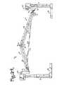
- FIGS. 31-33Another patient support structure according to the invention, generally 301 , is illustrated in FIGS. 31-33 .
- the structure 301generally includes a horizontally telescoping floor mounted base 302 , a conventional or standard telescoping and inclinable operating table support structure 304 , a telescoping end support or pier 306 and a hinged or pivotally upwardly and downwardly breaking support structure 310 connected to both the structure 304 and the pier 306 .
- the patient support structure 310further includes a first cantilevered section 312 and a second section 314 .
- the first section 312is fixed to and extends from the operating table support 304 .
- the second sectionis attached to the pier 306 by a hinge or pivoting assembly 320 , such as the support assembly 5 described herein with respect to the structure 1 .
- the hinge mechanism 316 disposed between the support sections 312 and 314may be a conventional hinge, pivot, or pivot or hinge systems previously described herein.
- the operating table support 304utilizes electric or other power means to move the support section 312 up and down and at an incline, as is known in the art.
- the section 314In response to the movement of the section 312 , the section 314 also moves, resulting in upward and downward breaking illustrated in FIGS. 32 and 33 .
- the electric powered telescoping base 302moves the pier 306 toward or away from the support 304 .
- the pier 306includes a motor for raising and lowering the pier at the connection 320 .
- cable drives as described hereinother types of drives including screw drives, hydraulic systems, and the like, may be utilized to facilitate both upward and downward breaking of the support structure 310 .
Landscapes
- Health & Medical Sciences (AREA)
- Life Sciences & Earth Sciences (AREA)
- Engineering & Computer Science (AREA)
- Animal Behavior & Ethology (AREA)
- General Health & Medical Sciences (AREA)
- Public Health (AREA)
- Veterinary Medicine (AREA)
- Biomedical Technology (AREA)
- Medical Informatics (AREA)
- Orthopedic Medicine & Surgery (AREA)
- Nursing (AREA)
- Pathology (AREA)
- High Energy & Nuclear Physics (AREA)
- Nuclear Medicine, Radiotherapy & Molecular Imaging (AREA)
- Optics & Photonics (AREA)
- Physics & Mathematics (AREA)
- Radiology & Medical Imaging (AREA)
- Heart & Thoracic Surgery (AREA)
- Molecular Biology (AREA)
- Surgery (AREA)
- Biophysics (AREA)
- Neurology (AREA)
- Neurosurgery (AREA)
- Accommodation For Nursing Or Treatment Tables (AREA)
Abstract
Description
This application is a continuation-in-part of U.S. application Ser No. 13/317,012 filed Oct. 6, 2011, now U.S. Pat. No. 8,719,979, entitled Patient Positioning Support Structure, which application is a continuation of U.S. Ser. No. 12/460,702, filed Jul. 23, 2009, now U.S. Pat. No. 8,060,960, which is a continuation of U.S. Ser. No. 11/788,513, filed Apr. 20, 2007, now U.S. Pat. No. 7,565,708, which claims the benefit of U.S. Provisional Application No. 60/798,288 filed May 5, 2006 and is also a continuation-in-part of U.S. patent application Ser. No. 11/159,494 filed Jun. 23, 2005, now U.S. Pat. No. 7,343,635, which is a continuation-in-part of U.S. patent application Ser. No. 11/062,775 filed Feb. 22, 2005, now U.S. Pat. No. 7,152,261. The disclosures of all the preceding applications and patents are incorporated by reference herein.
The present invention is directed to structure for use in maintaining a patient in a desired position during examination and treatment, including medical procedures such as imaging and surgery and in particular to such a structure that allows a surgeon to selectively position the patient for convenient access to the surgery site and providing for manipulation of the patient during surgery including the tilting, pivoting, angulating or bending of a trunk of a patient in a supine, prone or lateral position.
Current surgical practice incorporates imaging techniques and technologies throughout the course of patient examination, diagnosis and treatment. For example, minimally invasive surgical techniques, such as percutaneous insertion of spinal implants, involve small incisions that are guided by continuous or repeated intra-operative imaging. These images can be processed using computer software programs that produce three dimensional images for reference by the surgeon during the course of the procedure. If the patient support surface is not radiolucent or compatible with the imaging technologies, it may be necessary to interrupt the surgery periodically in order to remove the patient to a separate surface for imaging followed by transfer back to the operating support surface for resumption of the surgical procedure. Such patient transfers for imaging purposes may be avoided by employing radiolucent and other imaging compatible systems. The patient support system should also be constructed to permit unobstructed movement of the imaging equipment and other surgical equipment around, over and under the patient throughout the course of the surgical procedure without contamination of the sterile field.
It is also necessary that the patient support system be constructed to provide optimum access to the surgical field by the surgery team. Some procedures require positioning of portions of the patient's body in different ways at different times during the procedure. Some procedures, for example, spinal surgery, involve access through more than one surgical site or field. Since all of these fields may not be in the same plane or anatomical location, the patient support surfaces should be adjustable and capable of providing support in different planes for different parts of the patient's body as well as different positions or alignments for a given part of the body. Preferably, the support surface should be adjustable to provide support in separate planes and in different alignments for the head and upper trunk portion of the patient's body, the lower trunk and pelvic portion of the body as well as each of the limbs independently.
Certain types of surgery, such as orthopedic surgery, may require that the patient or a part of the patient be repositioned during the procedure while in some cases maintaining the sterile field. Where surgery is directed toward motion preservation procedures, such as by installation of artificial joints, spinal ligaments and total disc prostheses, for example, the surgeon must be able to manipulate certain joints while supporting selected portions of the patient's body during surgery in order to facilitate the procedure. It is also desirable to be able to test the range of motion of the surgically repaired or stabilized joint and to observe the gliding movement of the reconstructed articulating prosthetic surfaces or the tension and flexibility of artificial ligaments and other types of dynamic stabilizers before the wound is closed. Such manipulation can be used, for example, to verify the correct positioning and function of an implanted prosthetic disc or joint replacement during a surgical procedure. Where manipulation discloses binding, sub-optimal position or even crushing of the adjacent vertebrae, for example, as may occur with osteoporosis, the prosthesis can be removed and the adjacent vertebrae fused while the patient remains anesthetized. Injury which might otherwise have resulted from a “trial” use of the implant post-operatively will be avoided, along with the need for a second round of anesthesia and surgery to remove the implant or prosthesis and perform the revision, fusion or corrective surgery.
There is also a need for a patient support surface that can be rotated, articulated and angulated so that the patient can be moved from a prone to a supine position or from a prone to a 90° position and whereby intra-operative extension and flexion of at least a portion of the spinal column can be achieved. The patient support surface must also be capable of easy, selective adjustment without necessitating removal of the patient or causing substantial interruption of the procedure.
For certain types of surgical procedures, for example spinal surgeries, it may be desirable to position the patient for sequential anterior and posterior procedures. The patient support surface should also be capable of rotation about an axis in order to provide correct positioning of the patient and optimum accessibility for the surgeon as well as imaging equipment during such sequential procedures.
Orthopedic procedures may also require the use of traction equipment such as cables, tongs, pulleys and weights. The patient support system must include structure for anchoring such equipment and it must provide adequate support to withstand unequal forces generated by traction against such equipment.
Articulated robotic arms are increasingly employed to perform surgical techniques. These units are generally designed to move short distances and to perform very precise work. Reliance on the patient support structure to perform any necessary gross movement of the patient can be beneficial, especially if the movements are synchronized or coordinated. Such units require a surgical support surface capable of smoothly performing the multi-directional movements which would otherwise be performed by trained medical personnel. There is thus a need in this application as well for integration between the robotics technology and the patient positioning technology.
While conventional operating tables generally include structure that permits tilting or rotation of a patient support surface about a longitudinal axis, previous surgical support devices have attempted to address the need for access by providing a cantilevered patient support surface on one end. Such designs typically employ either a massive base to counterbalance the extended support member or a large overhead frame structure to provide support from above. The enlarged base members associated with such cantilever designs are problematic in that they may obstruct the movement of C-arm mobile fluoroscopic imaging devices. Surgical tables with overhead frame structures are bulky and may require the use of dedicated operating rooms, since in some cases they cannot be moved easily out of the way. Neither of these designs is easily portable or storable.
Thus, there remains a need for a patient support system that provides easy access for personnel and equipment, that can be easily and quickly positioned and repositioned in multiple planes without the use of massive counterbalancing support structure, and that does not require use of a dedicated operating room.
The present invention is directed to a patient support system that permits adjustable positioning, repositioning and selectively lockable support of a patient's head and upper body, lower body and limbs in up to a plurality of individual planes while permitting tilting, rotation, angulation or bending and other manipulations as well as full and free access to the patient by medical personnel and equipment. The system of the invention includes at least one support end or column that is height adjustable. The illustrated embodiment includes a pair of independently height-adjustable end support columns. The columns may be independent or connected to a horizontally length-adjustable base. One support column according to the invention may be coupled with a wall mount or other stationary support. A patient support structure is connected to and bridges substantially between the pair of end supports. The support structure may be a frame or other patient support having at least first and second hingeable or pivotally connected portions, the first and second portions being selectively lockable in a first substantially planar orientation along a longitudinal axis of the support structure. The first and second portions are also positionable and lockable in a plurality of angles with respect to one another, with each portion being movable to a position on either side of the first planar orientation. In other words, the patient support structure is capable of hinging or otherwise bending to form an angulation or break, either upwardly or downwardly when the support structure is in a substantially horizontal position and also when the support structure is in an inclined position due to one of the support columns raising one end of the structure higher than another end. Of course, such a break may be from side-to-side when the support structure is rotated about a longitudinal axis thereof.
In a particular illustrated embodiment, angulation or breaking of the support structure is supported by a cable drive system (tension band suspension) that supports angulation using stationary end supports. Other embodiments include cantilevered systems with connected or unconnected movable or telescoping base supports. The first and second support structure portions may be in the form of frames, such as rectangular frames or other support structure that may be equipped with support pads for holding the patient, or other structure, such as imaging tops.
The patient support structure and the support column or columns are coupled with respective rotation, articulation or angulation adjustment structure for positioning the first support portion with respect to a first column or end support and with respect to the second support portion and the second support portion with respect to the second column or end support. Rotation adjustment structure in cooperation with pivoting and height adjustment structure provide for the lockable positioning of the first and second patient support portions at a variety of selected positions and articulations with respect to the support columns including angulation coupled with Trendelenburg and reverse Trendelenburg configurations as well as providing for patient roll over in horizontal or tilted orientation. Lateral movement (toward and away from a surgeon) may also be provided by a bearing block feature. A pair of patient support structures (such as a support frame and an imaging table) may be mounted between end supports of the invention and then rotated in unison about a longitudinal axis to achieve 180° repositioning of a patient, from a prone to a supine position.
Various objects and advantages of this invention will become apparent from the following description taken in relation to the accompanying drawings wherein are set forth, by way of illustration and example, certain embodiments of this invention.
The drawings constitute a part of this specification, include exemplary embodiments of the present invention, and illustrate various objects and features thereof.
As required, detailed embodiments of the present invention are disclosed herein; however, it is to be understood that the disclosed embodiments are merely exemplary of the invention, which may be embodied in various forms. Therefore, specific structural and functional details disclosed herein are not to be interpreted as limiting, but merely as a basis for the claims and as a representative basis for teaching one skilled in the art to variously employ the present invention in virtually any appropriately detailed structure.
Referring now to the drawings, a patient positioning support structure according to the invention is generally designated by thereference numeral 1 and is depicted inFIGS. 1-12 . Thestructure 1 includes first and second upright support piers orcolumns 3 and4 which are illustrated as independent, stationary floor base support structures as shown inFIG. 1 or may be connected to one another by a non-telescoping base support as illustrated in the embodiment shown inFIGS. 25-28 . In some embodiments according to the invention as shown, for example, inFIGS. 31-33 , the base connection places the columns in a selectively telescoping relationship. It is also foreseen that in certain embodiments according to the invention, one of the support columns may be replaced by a conventional operating table support, or may even be a wall mount. In the illustrated embodiment, theupright support column 3 is connected to a first support assembly, generally5, and the upright support column4 is connected to a second support assembly, generally6. Between them, thesupport assemblies 5 and6 uphold an elongate and angulatable or breaking patient holding or support structure, generally10 and optionally, a removable patient support structure that will be described with respect to another embodiment of the invention. The illustrated support structure10 includes afirst frame section 12, asecond frame section 14 with a transverse support cross bar15, and a pivot or hinge assembly, generally16. In the illustrated embodiment, the pivot assembly further includes a cable drive system including adual winch 18 and cooperatingcables 20.
Thecolumns 3 and4 are supported by outwardly extendingfeet 22 that may or may not include spaced apart casters or wheels (not shown) each equipped with a floor-lock foot lever for lowering thefeet 12 into a floor-engaging position as shown inFIG. 1 . Thecolumns 3 and4 each include two or more telescopinglift arm segments columns 3 and4 to be selectively increased and decreased in order to raise and lower all or a selected portion of the connected patient support structure10. It is foreseen that thevertical supports 3 and4 may be constructed so that thecolumn 3 has a greater mass than the support column4 or vice versa in order to accommodate an uneven weight distribution of the human body. Such reduction in size at the foot end of thesystem 1 may be employed in some embodiments to facilitate the approach of personnel and equipment.
Each of thesupport assemblies 5 and6 generally includes arotation subassembly angulation subassembly FIG. 1 ) for cooperative and integrated actuation and operation. Therotational subassemblies hinge assembly 16 at desired levels and increments as well as selective tilting of the longitudinal axis of theframe portion
The rotation subassembly ormechanism 26 is shown inFIG. 5 and includes at least onemotor housing 30 surmounting thesupport column 3. In the illustrated embodiment, only one rotational motor is provided, but it is foreseen that a cooperating motor may also be mounted on the support column4. A main rotational shaft32 extends from themotor housing 30 that turns arotation structure 33. Therotation structure 33 in turn rotates the connected patient support10 about a longitudinal axis as will be described in greater detail below. Themotor housing 30 contains a rotary electric motor or other actuator drivingly engaged with the shaft32. Therotation mechanism 26 is operated by actuating the motor using a switch or other similar means. Therotation structure 33 is fixed to the shaft32 at a location spaced from themotor housing 30 and thesupport column 3 to provide clearance for rotation of the connected patient support structure10.
As shown inFIG. 5 , therotation structure 33 is attached to a pair of translation posts or H-bar posts 40 disposed at either end of therotation structure 33. Theposts 40 are each attached to thestructure 33 by apin 42, bolt, or other fixing structure. A plurality of cooperatingapertures 44 formed in theposts 40 provide passageway for a pivot pin46 to extend therethrough. The pivot pin46 is receivable in each cooperating pair ofapertures 44 allowing for selective placement of atranslation connector 48 that is sized and shaped to be received between the pair ofposts 40 and also receive the pivot pin46 therethrough. The pin46 andconnector 48 are thus positionable in an orientation transverse to the longitudinal extension of the support10 at a variety of heights to be selected by the surgeon and readily changeable, even during surgery if necessary, to vary the height of theframe section 12. The multiple location or height feature is also advantageous when more than one frame or patent structure is mounted in tandem as shown, for example inFIGS. 25-28 . The position of the frame or other structure may be desirably changed to provide close proximity to an imaging top with a distance between a patient support and an imaging top being expandable or reduceable depending upon the size or other attributes of a patient and surgical or other requirements. As illustrated inFIG. 5 , theconnector 48 has a slot50 for receiving the pivot pin46.
Thetranslation connector 48 is in turn attached to apivot connector 52. Thepivot connector 52 includes first and second outwardly opening and opposed slots54 and56. The first slot54 is sized and shaped for receiving thetranslation connector 48 and the second slot is sized and shaped for receiving anend connection 58 of theframe section 12. Thepivot connector 52 further includes a through aperture or bore60 running substantially perpendicular to the slot54 and communicating therewith. Theaperture 60 is sized and shaped to receive a pivot pin62 therethrough, allowing for some forward and rearward lateral movement of the attachedframe end connection 58 and thus theframe section 12, providing a degree of freedom and clearance needed for rotation the patient support about a longitudinal axis of a patient. The slot56 is sized and shaped to frictionally engage theframe end connection 58, thus securely fixing theend connection 58 to thepivot connector 52. Theframe end connection 58 is in turn fixed to each ofelongate frame members frame section 12. Theframe members hinge assembly 16 to be described in greater detail below. Pivoting of thetranslation connector 48 with respect to the pin46 provides for selected articulation of the frame section12 (that includes theend connection 58 and theframe members 66 and68) and/or the entire support10 with respect to the support pier orcolumn 3.
With reference toFIG. 6 , at the support pier or column4, thesupport assembly 6 is substantially similar to the support assembly5 with the exception that therotation subassembly 26′ is passive and therefore does not include a motor. However, the support pier or column4 preferably includes a powered mechanism to provide selective height adjustment of thesubassembly 26′. Arotation structure 33′ is spaced from and freely rotatable with respect to the column4. Thestructure 33′ includes a shaft (not shown) extending outwardly therefrom similar to the rotation shaft32, the shaft being rotatingly received in an aperture in the support column4.
Therotation subassembly 26′ and theangulation subassembly 27 otherwise include elements identical to or substantially similar to the elements of thesubassemblies bar posts 40′, pin42′,apertures 44′, pivot pin46′,translation connector 48′, slot50′,pivot connector 52′,end connector 58′ and pivot pin62′, are identical or substantially similar in form and cooperate with other elements identically or substantially similarly to what has been described previously herein with respective H-bar posts 40,pin 42,apertures 44, pivot pin46,translation connector 48, slot50,pivot connector 52,end connector 58 and pivot pin62.
Theframe 14 further includesframe members 66′ and68′ that are each fixed to theend connector 58′. Theframe members 66′ and68′ are pivotably or hingedly connected torespective frame members hinge assembly 16. Specifically, theframe member 66 is attached to theframe member 66′ by the hinge mechanism70 and theframe member 68 is attached to theframe member 68′ by the hinge mechanism72. With particular reference to FIGS.7 and9-11, the hinge mechanism70 includes anouter member 76 and aninner member 78. Theouter member 76 is fixed or may be integral with theelongate frame member 66, while theinner member 78 is integral or otherwise fixed to theframe member 66′. Theouter member 76 further includes anextension 80 with a groove82 for receiving and guiding thecable 20. Theextension 89 tapers in a direction from the outer member interior84 to the groove82. Theextension 89 is configured to cause a slight upward break or bend of the support10 when theextension 89 comes into contact with thecable 20 at the groove82. In that way, when thecables 20 are reeled in to shorten the hypotenuse of the triangle formed by the cable, thesection 12 and thesection 14, thesections FIG. 18 . The downward break illustrated, for example, inFIG. 21 is a result of lengthening thecable 20 distance and allowing gravity to drop the hinge70. Theextension 89 is shaped to extend slightly inwardly toward a longitudinal axis A of the support10, thereby guiding thecable 20 along a path within a periphery of theframe sections extension 89 is in contact with thecable 20 when in a downward breaking configuration directed toward the cable with thecable 20 being received at the groove82.
It is foreseen that where an upward breaking (only) embodiment is desired according to the invention, thesections sections sections sections frames sections
Returning to the hinge70 of illustrated embodiment, theinner member 78 is slidingly and rotatably receivable in an interior84 of theouter member 76. The outer member has a pair ofpivot apertures 86 and the inner member has apivot aperture 87, the apertures cooperating to create a through bore for receiving a pivot pin88 through both the inner and outer hinge members. The interior84 includes a curved partiallycylindrical surface 89 for slidingly receiving a cooperating outer rounded and partially cylindrical surface90 of theinner member 78. Theinner member 78 further includes a downward breaking stop orprojection 92 that limits a downward pivot (in a direction toward the cables20) of the hinge70 in the event thecables 20 should fail. Thestop 92 abuts against asurface 93 of the interior84. In the illustrated embodiment, thestop 92 limits the extent of rotation or hinging of thesection 66 with respect to thesection 66′ to about twenty-five degrees. Upward pivot (in a direction away from the cables20) is limited by abutment of an innerplanar surface 95 with aplanar surface 96 of the hingeinner member 78.
With particular reference toFIG. 8 , the hinge mechanism72 is substantially a mirror image of the hinge mechanism70 and therefore includes the following elements: a hingeouter member 76′, andinner member 78′, andextension 80′ with a groove82′, and interior84′pivot apertures 86′ and88′, a pivot pin88′, acurved surface 89′, and outer surface90′, astop 92′, anabutment surface 93′, an innerplanar surface 95′ and aplanar surface 96′. These elements are substantially similar in shape and function to the respective hingeouter member 76,inner member 78,extension 80, groove82, interior84,pivot apertures 86 and88, pivot pin88,curved surface 89, outer surface90, stop92,abutment surface 93, innerplanar surface 95 andplanar surface 96 described herein with respect to the hinge70.
It is noted that other hinge or pivot mechanisms may be utilized in lieu of thehinge assembly 16. For example, the polyaxial joint95 illustrated and described in Applicant's pending U.S. patent application Ser. No. 11/062,775 filed Feb. 22, 2005, and pending U.S. patent application Ser. No. 11/159,494 filed Jun. 23, 2005, may be incorporated into the patient support structure10 at the break between thesections
Thecable drive system 18 includes a rotary motor98 cooperating with and driving by rotation a pair ofwinch cylinders 99 disposed on either side of the motor98. The motor98 andcylinders 99 are mounted to theend connector 58′ located near the support column4. Eachcable 20 is attached to one of thewinch cylinders 99 at one end thereof and to theend connector 58 at the other end thereof. In a first longitudinal position wherein thesection 12 is substantially planar with thesection 14, thecables 20 are wound about thewinch cylinders 99 an amount to provide enough tension in thecables 20 to maintain such a substantially planar orientation and configuration, with the hinge extensions82 and82′ being in contact with each of thecables 20. The motor98 is preferably low speed and high torque for safely winding both of thecables 20 simultaneously about thecylinders 99 to draw thesection 12 toward thesection 14 to result in an upward breaking configuration with the hinges70 and72 disposed in spaced relation with thecables 20 and the hinges70 and72. The motor98 may be reversed, reversing the direction of rotation of thewinch cylinders 99 for slowly unwinding thecables 20 to a downward breaking configuration. As thecables 20 unwind, gravity draws thesupport sections cables 20 being received in the grooves82 and82′ of thehinge extensions cables 20 slacken, the hinges70 and72 continue to lower pressing down upon thecables 20.
It is noted that theframe sections FIGS. 13 and 14 , theframe member sections section 12 and theframe member sections 66′ and68′ of thesection 14 may be replaced with substantially rectangular imaging tops or sections100 and101′ respectively. Each of the sections100 and101′ having elongate slots101 formed therein to allow for attachment of the hinge mechanisms70 and72 in a manner identical or substantially similar to what has been described herein with respect to theframe sections
With reference toFIGS. 15-17 , the imaging sections100 and100′ are illustrated, replacing theframe sections FIGS. 1-12 . Each ofFIGS. 15-17 represent configurations in which thecable drive 18 is tensioned such that the sections100 and100′ are kept in a substantially coplanar configuration.FIG. 15 illustrates a configuration in which thecolumn 3 is telescoped upwardly with the frame sections hinging at thesupport assemblies 5 and6, resulting in an inclined position or configuration of the entire patient support. In the illustrated embodiment, the section100 would preferably receive a patient's head. Therefore,FIG. 15 illustrates a reverse Trendelenburg position or orientation.FIG. 16 illustrates the sections100 and100′ again in a substantially common plane with both sections being rotated to a tilted position produced by a powered rotation of the rotation thesub assemblies 26 and passive rotation of theassembly 26′ with bothcolumns 3 and4 otherwise holding the sections100 and100′ at the same height.FIG. 17 illustrates both tilting due to rotation of theassemblies FIG. 17 illustrates a Trendelenburg position or orientation with both the sections100 and100′ remaining in substantially the same plane.
With reference toFIGS. 18-20 , there is illustrated three upward breaking or hinging configurations of thestructure 1.FIG. 18 illustrates a symmetrical upward breaking configuration wherein thecolumns 3 and4 are holding therespective support assemblies 5 and6 at substantially the same height with thecables 20 being shortened by rotation of the winch motor to result in an upward break in thehinge assembly 16.FIG. 19 illustrates thecolumn 3 being extended to a maximum height and the cables reeled to shorten a distance between the sections100 and100′. An example of such an upward break with reverse Trendelenburg would be a head orcolumn 3 height of 43 inches, a foot or column4 height of 24 inches and a 35 degree upward break with zero degree roll.FIG. 20 illustrates an upward breaking Trendelenburg with the column4 being extended to a maximum height.
With reference toFIGS. 21-23 , there is illustrated three downward breaking configurations of thestructure 1.FIG. 21 illustrates a symmetrical downward breaking configuration wherein thecolumns 3 and4 are holding thesupport assemblies 5 and6 respectively, at the same height with thecables 20 being unwound or slackened to result in a downward break in thehinge assembly 16, the hinges70 and72 contacting thecables 20.FIG. 22 illustrates a downward breaking reverse Trendelenburg with thecolumn 3 being extended to a maximum height resulting in a patent's head end being at a maximum height.FIG. 23 illustrates a downward breaking Trendelenburg with the column4 being extended to a maximum height.
It is noted that in each of the configurations illustrated inFIGS. 18-23 , thesub assemblies 26 may be rotated in either direction, resulting in a tilted or rotated as well as upwardly or downwardly broken or hinged configuration. For example,FIG. 24 illustrates thestructure 1 withsupport frame sections FIG. 19 , but also including rotation, resulting in a tilting and upwardly breaking configuration of thestructure 1. An example of the position illustrated inFIG. 24 would be: a head orcolumn 3 height of 41 inches, a foot or column4 height of 34 inches and a 35 degree upward break with 10 degree roll.
With reference toFIGS. 25-28 , another structure, generally102 according to the invention is illustrated. Thestructure 102 utilizes all of the elements described herein with respect to thestructure 1 and therefore the same references numerals are used for the same elements or features. Thestructure 102 differs from thestructure 1 in that the H-bar posts bar posts FIG. 25 , one of the structures10 includes theframe member bar posts FIGS. 25-28 , thestructure 102 provides for the complete rotation and thus a roll-over of a patient by actuation of the motor of therotation subassembly 26 using the controller29. Thestructure 102 is further illustrated with a non-telescoping base support110 fixed to each of thecolumns 3 and4 and rollers orcastors 112 at the base of thestructure 102.
With reference toFIGS. 29 and 30 , another embodiment or system according to the invention, generally200 is illustrated. The system200 broadly includes an elongate length-adjustable base202 surmounted at either end by respective first and second upright support piers orcolumns support assemblies FIG. 30 differs from the structure200 only in that the length-adjustable base202 is replaced by afirst base 220 attached to thepier 203 and a second base222 attached to thepier 204. All of thebases 202,220 and222 include castors orrollers 230 or some other movable structure to allow thepiers structure 210.
It is foreseen that cable drives as described herein, other types of motor drives including screw drives, hydraulic systems, and the like, may be utilized to facilitate both upward and downward breaking of thesupport structure 210.
Another patient support structure according to the invention, generally301, is illustrated inFIGS. 31-33 . The structure301 generally includes a horizontally telescoping floor mountedbase 302, a conventional or standard telescoping and inclinable operatingtable support structure 304, a telescoping end support orpier 306 and a hinged or pivotally upwardly and downwardly breakingsupport structure 310 connected to both thestructure 304 and thepier 306. Thepatient support structure 310 further includes a firstcantilevered section 312 and asecond section 314. Thefirst section 312 is fixed to and extends from theoperating table support 304. The second section is attached to thepier 306 by a hinge or pivotingassembly 320, such as the support assembly5 described herein with respect to thestructure 1. Thehinge mechanism 316 disposed between thesupport sections
In use, theoperating table support 304 utilizes electric or other power means to move thesupport section 312 up and down and at an incline, as is known in the art. In response to the movement of thesection 312, thesection 314 also moves, resulting in upward and downward breaking illustrated inFIGS. 32 and 33 . In response to the movement of thesection 312, the electric poweredtelescoping base 302 moves thepier 306 toward or away from thesupport 304. Thepier 306 includes a motor for raising and lowering the pier at theconnection 320.
As stated above with respect to other embodiments of the invention described herein, it is foreseen that cable drives as described herein, other types of drives including screw drives, hydraulic systems, and the like, may be utilized to facilitate both upward and downward breaking of thesupport structure 310.
It is to be understood that while certain forms of the present invention have been illustrated and described herein, it is not to be limited to the specific forms or arrangement of parts described and shown.
Claims (19)
1. A surgical table comprising: A) a patient support comprising a first end, a second end opposite the first end, and a joint intermediate the first and second ends and about which the first and second ends articulate relative to each other; B) a first vertical support supporting a first displacement apparatus operably coupling the first vertical support to the first end of the patient support, the first displacement apparatus comprising: i) a first longitudinal pivot operably coupled with the first vertical support and configured to facilitate the patient support pivoting about a longitudinal axis of the patient support; ii) a first transverse pivot operably coupled with the first end of the patient support and configured to facilitate the first end pivoting relative to the first vertical support when the first and second ends articulate relative to each other about the joint; and iii) a linear translation member operatively coupled between the first transverse pivot and the first end of the patient support, the linear translation member configured to facilitate the first end of the patient support translating such that a distance between the first end and the first vertical support changes as the first and second ends articulate relative to each other about the joint; and C) a second vertical support supporting a second displacement apparatus operably coupling the second vertical support to the second end of the patient support, the second displacement apparatus comprising: i) a second longitudinal pivot operably coupled with the second vertical support and configured to facilitate the patient support pivoting about the longitudinal axis of the patient support; and ii) a second transverse pivot operably coupled with the second end of the patient support and configured to facilitate the second end pivoting relative to the second vertical support when the first and second ends articulate relative to each other about the joint.
2. The surgical table ofclaim 1 , wherein the first displacement apparatus further comprises a first vertically extending member operably coupling the first longitudinal pivot with the first transverse pivot.
3. The surgical table ofclaim 2 , wherein the second displacement apparatus further comprises a second vertically extending member operably coupling the second longitudinal pivot with the second transverse pivot.
4. The surgical table ofclaim 3 , wherein, when the patient support faces generally upward, the first transverse pivot is located below the first longitudinal pivot, and the second transverse pivot is located below the second longitudinal pivot.
5. The surgical table ofclaim 1 , wherein the first vertical support comprises a telescopic configuration by which a height of the first vertical support is adjusted, and the second vertical support comprises a telescopic configuration by which a height of the second vertical support is adjusted.
6. The surgical table ofclaim 5 , wherein the respective heights of the first and second vertical supports are independently adjustable such that the respective heights may be caused to be the same and different according to how the respective heights are set.
7. The surgical table ofclaim 5 , wherein the first displacement apparatus is configured to allow adjustment of a vertical distance between the first transverse pivot and a top of the first vertical support.
8. The surgical table ofclaim 7 , wherein a height of the first transverse pivot is adjustable via the first displacement apparatus and the telescopic configuration of the first vertical support, individually or in combination.
9. The surgical table ofclaim 8 , wherein the first displacement apparatus further comprises a vertically extending member operably coupling in an adjustable manner the top of the first vertical support to the first transverse pivot.
10. The surgical table ofclaim 9 , wherein the vertically extending member comprises a plurality of spaced-apart pin holes by which the vertical distance between the first transverse pivot and the top of the first vertical support is adjusted.
11. The surgical table ofclaim 1 , further comprising a drive assembly intersecting the patient support at a first location and a second location spaced apart from the first location, wherein the drive system applies a force to the patient support at the first and second locations in causing the first and second ends to articulate relative to each other about the joint.
12. The surgical table ofclaim 11 , wherein the first location and the second location are on opposite sides of the joint.
13. The surgical table ofclaim 11 , wherein the patient support further comprise a first segment and a second segment, the first segment extending between the joint and the first end, the second segment extending between the joint and the second end, the first and second segments articulating relative to each other when the first and second ends articulate relative to each other, wherein the drive assembly comprises an element that extends along at least one of the first segment or second segment, the element transmitting the force to the first and second locations.
14. The surgical table ofclaim 13 , wherein the element comprises a cable.
15. The surgical table ofclaim 13 , wherein the element comprises a screw drive.
16. The surgical table ofclaim 13 , wherein the drive assembly further comprises a motor supported on the patient support and configured to apply the force to the first and second locations via the element.
17. The surgical table ofclaim 1 , wherein the first longitudinal pivot is perpendicular to the first transverse pivot, and the second longitudinal pivot is perpendicular to the second transverse pivot.
18. The surgical table ofclaim 1 , wherein at least one of the first displacement apparatus or second displacement apparatus further comprises a vertical pivot configured to allow for lateral movement of a frame of the patient support such that there is a sufficient degree of freedom for the patient support to pivot about the longitudinal axis of the patient support.
19. The surgical table ofclaim 18 , wherein the vertical pivot is located between at least one of the first or second longitudinal pivot and a corresponding of the first or second end.
Priority Applications (1)
| Application Number | Priority Date | Filing Date | Title |
|---|---|---|---|
| US13/902,487US8856986B2 (en) | 2005-02-22 | 2013-05-24 | Patient positioning support structure |
Applications Claiming Priority (7)
| Application Number | Priority Date | Filing Date | Title |
|---|---|---|---|
| US11/062,775US7152261B2 (en) | 2005-02-22 | 2005-02-22 | Modular multi-articulated patient support system |
| US11/159,494US7343635B2 (en) | 2005-02-22 | 2005-06-23 | Modular multi-articulated patient support system |
| US79828806P | 2006-05-05 | 2006-05-05 | |
| US11/788,513US7565708B2 (en) | 2005-02-22 | 2007-04-20 | Patient positioning support structure |
| US12/460,702US8060960B2 (en) | 2005-02-22 | 2009-07-23 | Patient positioning support structure |
| US13/317,012US8719979B2 (en) | 2005-02-22 | 2011-10-06 | Patient positioning support structure |
| US13/902,487US8856986B2 (en) | 2005-02-22 | 2013-05-24 | Patient positioning support structure |
Related Parent Applications (2)
| Application Number | Title | Priority Date | Filing Date |
|---|---|---|---|
| US13/317,012ContinuationUS8719979B2 (en) | 2005-02-22 | 2011-10-06 | Patient positioning support structure |
| US13/317,012Continuation-In-PartUS8719979B2 (en) | 2005-02-22 | 2011-10-06 | Patient positioning support structure |
Publications (2)
| Publication Number | Publication Date |
|---|---|
| US20130318719A1 US20130318719A1 (en) | 2013-12-05 |
| US8856986B2true US8856986B2 (en) | 2014-10-14 |
Family
ID=38668395
Family Applications (26)
| Application Number | Title | Priority Date | Filing Date |
|---|---|---|---|
| US11/788,513Expired - Fee RelatedUS7565708B2 (en) | 2005-02-22 | 2007-04-20 | Patient positioning support structure |
| US12/460,702Expired - LifetimeUS8060960B2 (en) | 2005-02-22 | 2009-07-23 | Patient positioning support structure |
| US13/317,012Expired - LifetimeUS8719979B2 (en) | 2005-02-22 | 2011-10-06 | Patient positioning support structure |
| US13/815,982Expired - LifetimeUS9211223B2 (en) | 2005-02-22 | 2013-03-20 | Patient positioning support structure |
| US13/902,487Expired - LifetimeUS8856986B2 (en) | 2005-02-22 | 2013-05-24 | Patient positioning support structure |
| US13/902,466Expired - LifetimeUS9205013B2 (en) | 2005-02-22 | 2013-05-24 | Patient positioning support structure |
| US13/902,525Expired - LifetimeUS8826474B2 (en) | 2005-02-22 | 2013-05-24 | Modular multi-articulated patient support system |
| US13/902,565Expired - LifetimeUS9198817B2 (en) | 2005-02-22 | 2013-05-24 | Patient positioning support structure |
| US13/902,479Expired - LifetimeUS8839471B2 (en) | 2005-02-22 | 2013-05-24 | Patient positioning support structure |
| US13/902,510Expired - LifetimeUS8826475B2 (en) | 2005-02-22 | 2013-05-24 | Modular multi-articulated patient support system |
| US13/902,536Expired - LifetimeUS8978180B2 (en) | 2005-02-22 | 2013-05-24 | Modular multi-articulated patient support system |
| US13/902,550Expired - LifetimeUS9289342B2 (en) | 2005-02-22 | 2013-05-24 | Patient positioning support structure |
| US13/902,577Expired - LifetimeUS9180062B2 (en) | 2005-02-22 | 2013-05-24 | Patient positioning support structure |
| US13/902,455Expired - LifetimeUS8938826B2 (en) | 2005-02-22 | 2013-05-24 | Patient positioning support structure |
| US14/096,875Expired - LifetimeUS9364380B2 (en) | 2005-02-22 | 2013-12-04 | Patient positioning support structure |
| US14/218,599Expired - LifetimeUS9610206B2 (en) | 2005-02-22 | 2014-03-18 | Patient positioning support structure |
| US14/218,667AbandonedUS20140201914A1 (en) | 2005-02-22 | 2014-03-18 | Patient positioning support structure |
| US14/218,431Expired - LifetimeUS9456945B2 (en) | 2005-02-22 | 2014-03-18 | Patient positioning support structure |
| US14/230,432Expired - LifetimeUS9757300B2 (en) | 2005-02-22 | 2014-03-31 | Patient positioning support structure |
| US14/328,058AbandonedUS20140317847A1 (en) | 2005-02-22 | 2014-07-10 | Patient positioning support structure |
| US14/616,500AbandonedUS20150150743A1 (en) | 2005-02-22 | 2015-02-06 | Modular multi-articulated patient support system |
| US14/923,044AbandonedUS20160038364A1 (en) | 2005-02-22 | 2015-10-26 | Patient Positioning Support Structure |
| US15/431,439Active2026-02-17US10835438B2 (en) | 2005-02-22 | 2017-02-13 | Modular multi-articulated patient support system |
| US15/631,911Active2026-09-04US10695252B2 (en) | 2005-02-22 | 2017-06-23 | Patient positioning support structure |
| US16/884,947Active2026-06-10US11679051B2 (en) | 2005-02-22 | 2020-05-27 | Patient positioning support structure |
| US16/910,489Active2026-12-24US12076281B2 (en) | 2005-02-22 | 2020-06-24 | Modular multi-articulated patient support system |
Family Applications Before (4)
| Application Number | Title | Priority Date | Filing Date |
|---|---|---|---|
| US11/788,513Expired - Fee RelatedUS7565708B2 (en) | 2005-02-22 | 2007-04-20 | Patient positioning support structure |
| US12/460,702Expired - LifetimeUS8060960B2 (en) | 2005-02-22 | 2009-07-23 | Patient positioning support structure |
| US13/317,012Expired - LifetimeUS8719979B2 (en) | 2005-02-22 | 2011-10-06 | Patient positioning support structure |
| US13/815,982Expired - LifetimeUS9211223B2 (en) | 2005-02-22 | 2013-03-20 | Patient positioning support structure |
Family Applications After (21)
| Application Number | Title | Priority Date | Filing Date |
|---|---|---|---|
| US13/902,466Expired - LifetimeUS9205013B2 (en) | 2005-02-22 | 2013-05-24 | Patient positioning support structure |
| US13/902,525Expired - LifetimeUS8826474B2 (en) | 2005-02-22 | 2013-05-24 | Modular multi-articulated patient support system |
| US13/902,565Expired - LifetimeUS9198817B2 (en) | 2005-02-22 | 2013-05-24 | Patient positioning support structure |
| US13/902,479Expired - LifetimeUS8839471B2 (en) | 2005-02-22 | 2013-05-24 | Patient positioning support structure |
| US13/902,510Expired - LifetimeUS8826475B2 (en) | 2005-02-22 | 2013-05-24 | Modular multi-articulated patient support system |
| US13/902,536Expired - LifetimeUS8978180B2 (en) | 2005-02-22 | 2013-05-24 | Modular multi-articulated patient support system |
| US13/902,550Expired - LifetimeUS9289342B2 (en) | 2005-02-22 | 2013-05-24 | Patient positioning support structure |
| US13/902,577Expired - LifetimeUS9180062B2 (en) | 2005-02-22 | 2013-05-24 | Patient positioning support structure |
| US13/902,455Expired - LifetimeUS8938826B2 (en) | 2005-02-22 | 2013-05-24 | Patient positioning support structure |
| US14/096,875Expired - LifetimeUS9364380B2 (en) | 2005-02-22 | 2013-12-04 | Patient positioning support structure |
| US14/218,599Expired - LifetimeUS9610206B2 (en) | 2005-02-22 | 2014-03-18 | Patient positioning support structure |
| US14/218,667AbandonedUS20140201914A1 (en) | 2005-02-22 | 2014-03-18 | Patient positioning support structure |
| US14/218,431Expired - LifetimeUS9456945B2 (en) | 2005-02-22 | 2014-03-18 | Patient positioning support structure |
| US14/230,432Expired - LifetimeUS9757300B2 (en) | 2005-02-22 | 2014-03-31 | Patient positioning support structure |
| US14/328,058AbandonedUS20140317847A1 (en) | 2005-02-22 | 2014-07-10 | Patient positioning support structure |
| US14/616,500AbandonedUS20150150743A1 (en) | 2005-02-22 | 2015-02-06 | Modular multi-articulated patient support system |
| US14/923,044AbandonedUS20160038364A1 (en) | 2005-02-22 | 2015-10-26 | Patient Positioning Support Structure |
| US15/431,439Active2026-02-17US10835438B2 (en) | 2005-02-22 | 2017-02-13 | Modular multi-articulated patient support system |
| US15/631,911Active2026-09-04US10695252B2 (en) | 2005-02-22 | 2017-06-23 | Patient positioning support structure |
| US16/884,947Active2026-06-10US11679051B2 (en) | 2005-02-22 | 2020-05-27 | Patient positioning support structure |
| US16/910,489Active2026-12-24US12076281B2 (en) | 2005-02-22 | 2020-06-24 | Modular multi-articulated patient support system |
Country Status (7)
| Country | Link |
|---|---|
| US (26) | US7565708B2 (en) |
| EP (1) | EP2015725A4 (en) |
| JP (5) | JP2009534159A (en) |
| KR (1) | KR101279010B1 (en) |
| AU (3) | AU2007248426B2 (en) |
| CA (1) | CA2649350C (en) |
| WO (1) | WO2007130679A2 (en) |
Cited By (35)
| Publication number | Priority date | Publication date | Assignee | Title |
|---|---|---|---|---|
| US9186291B2 (en) | 2005-02-22 | 2015-11-17 | Roger P. Jackson | Patient positioning support structure with trunk translator |
| US9198817B2 (en) | 2005-02-22 | 2015-12-01 | Roger P. Jackson | Patient positioning support structure |
| US9226865B2 (en) | 2005-02-22 | 2016-01-05 | Roger P. Jackson | Patient positioning support structure |
| US9295433B2 (en) | 2005-02-22 | 2016-03-29 | Roger P. Jackson | Synchronized patient elevation and positioning apparatus for use with patient positioning support systems |
| US9308145B2 (en) | 2005-02-22 | 2016-04-12 | Roger P. Jackson | Patient positioning support structure |
| US9339430B2 (en) | 2006-05-05 | 2016-05-17 | Roger P. Jackson | Patient positioning support apparatus with virtual pivot-shift pelvic pads, upper body stabilization and fail-safe table attachment mechanism |
| US9358170B2 (en) | 2007-10-22 | 2016-06-07 | Roger P Jackson | Surgery table apparatus |
| US9402775B2 (en) | 2014-07-07 | 2016-08-02 | Roger P. Jackson | Single and dual column patient positioning and support structure |
| US9468576B2 (en) | 2005-02-22 | 2016-10-18 | Roger P. Jackson | Patient support apparatus with body slide position digitally coordinated with hinge angle |
| US9549863B2 (en) | 2014-07-07 | 2017-01-24 | Roger P. Jackson | Surgical table with pivoting and translating hinge |
| US9561145B2 (en) | 2012-02-07 | 2017-02-07 | Roger P. Jackson | Fail-safe release mechanism for use with patient positioning support apparati |
| US9642760B2 (en) | 2006-05-05 | 2017-05-09 | Roger P. Jackson | Patient positioning support apparatus with virtual pivot-shift pelvic pads, upper body stabilization and fail-safe table attachment mechanism |
| US9744087B2 (en) | 2005-02-22 | 2017-08-29 | Roger P. Jackson | Patient support apparatus with body slide position digitally coordinated with hinge angle |
| US9849054B2 (en) | 2005-02-22 | 2017-12-26 | Roger P. Jackson | Patient positioning support structure |
| US9968503B2 (en) | 2012-04-16 | 2018-05-15 | Allen Medical Systems, Inc. | Dual column surgical table having a single-handle unlock for table rotation |
| US10363189B2 (en) | 2015-10-23 | 2019-07-30 | Allen Medical Systems, Inc. | Surgical patient support for accommodating lateral-to-prone patient positioning |
| US10426684B2 (en) | 2015-06-11 | 2019-10-01 | Allen Medical Systems, Inc. | Person support apparatuses including person repositioning assemblies |
| US10492973B2 (en) | 2015-01-05 | 2019-12-03 | Allen Medical Systems, Inc. | Dual modality prone spine patient support apparatuses |
| US10548793B2 (en) | 2016-06-14 | 2020-02-04 | Allen Medical Systems, Inc. | Pinless loading for spine table |
| US10561559B2 (en) | 2015-10-23 | 2020-02-18 | Allen Medical Systems, Inc. | Surgical patient support system and method for lateral-to-prone support of a patient during spine surgery |
| USD878836S1 (en) | 2017-08-17 | 2020-03-24 | Stryker Corp. | Table extender |
| US10828218B2 (en) | 2015-06-05 | 2020-11-10 | Stryker Corporation | Surgical table and accessories to facilitate hip arthroscopy |
| US10857054B2 (en) | 2015-11-13 | 2020-12-08 | Allen Medical Systems, Inc. | Person support apparatuses for subject repositioning |
| US10869798B2 (en) | 2006-05-05 | 2020-12-22 | Warsaw Orthopedic, Inc. | Patient positioning support apparatus with virtual pivot-shift pelvic pads, upper body stabilization and fail-safe table attachment mechanism |
| US11051770B2 (en) | 2005-02-22 | 2021-07-06 | Warsaw Orthopedic, Inc. | Patient positioning support structure |
| US11160709B2 (en) | 2016-06-14 | 2021-11-02 | Warsaw Orthopedic, Inc. | Surgical table with movement capabilities of lower body support structures |
| US11202731B2 (en) | 2018-02-28 | 2021-12-21 | Allen Medical Systems, Inc. | Surgical patient support and methods thereof |
| US11213448B2 (en) | 2017-07-31 | 2022-01-04 | Allen Medical Systems, Inc. | Rotation lockout for surgical support |
| US11241350B2 (en) | 2018-08-31 | 2022-02-08 | Hill-Rom Services, Inc. | Patient turning system |
| US11471354B2 (en) | 2018-08-30 | 2022-10-18 | Allen Medical Systems, Inc. | Patient support with selectable pivot |
| US11510805B2 (en) | 2017-02-06 | 2022-11-29 | Stryker Corp. | Anatomical gripping system for gripping the leg and foot of a patient when effecting hip distraction and/or when effecting leg positioning |
| US11559455B2 (en) | 2017-02-06 | 2023-01-24 | Stryker Corp. | Distraction frame for effecting hip distraction |
| US11564855B2 (en) | 2020-09-28 | 2023-01-31 | Stryker Corporation | Systems and methods for supporting and stabilizing a patient during hip distraction |
| US11684532B2 (en) | 2017-02-06 | 2023-06-27 | Stryker Corp. | Method and apparatus for supporting and stabilizing a patient during hip distraction |
| US12011399B2 (en) | 2013-08-28 | 2024-06-18 | Warsaw Orthopedic, Inc. | Patient positioning support apparatus with fail-safe connector attachment mechanism |
Families Citing this family (120)
| Publication number | Priority date | Publication date | Assignee | Title |
|---|---|---|---|---|
| US20130133137A1 (en)* | 2011-11-28 | 2013-05-30 | Roger P. Jackson | Patient positioning support structure with coordinated continuous nonsegmented articulation, rotation and lift, and locking fail-safe device |
| US9265679B2 (en) | 2005-02-22 | 2016-02-23 | Roger P Jackson | Cantilevered patient positioning support structure |
| US9301897B2 (en) | 2005-02-22 | 2016-04-05 | Roger P. Jackson | Patient positioning support structure |
| US8844077B2 (en) | 2005-02-22 | 2014-09-30 | Roger P. Jackson | Syncronized patient elevation and positioning apparatus positioning support systems |
| AU2006283126A1 (en)* | 2005-08-24 | 2007-03-01 | Thomson Licensing | Method for graphical scaling of LCDs in mobile television devices |
| US8864205B2 (en) | 2006-06-28 | 2014-10-21 | Stryker Corporation | Patient support with wireless data and/or energy transfer |
| EP2046259B1 (en)* | 2006-06-28 | 2014-07-02 | Stryker Corporation | Patient support |
| CZ18426U1 (en)* | 2008-02-15 | 2008-04-07 | Linet, Spol. S R.O. | Bed positioning mechanism |
| KR100950162B1 (en)* | 2008-03-05 | 2010-03-30 | 유영선 | Body stretching bed |
| US8635725B2 (en)* | 2008-10-28 | 2014-01-28 | Tony Y. Tannoury | Prone and laterally angled surgical device and method |
| FR2940130B1 (en)* | 2008-12-19 | 2012-04-13 | Roussy Inst Gustave | PATIENT ORIENTATION AND CONTENT DEVICE FOR HADRONTHERAPY TREATMENT |
| US20100234771A1 (en)* | 2009-03-11 | 2010-09-16 | Patrick Ingrassia | Massage bench |
| US8707476B2 (en) | 2009-04-01 | 2014-04-29 | Operating Room Safety Enterprises, LLC | Apparatuses for posterior surgery |
| US8381331B2 (en) | 2009-04-01 | 2013-02-26 | Operating Room Safety Enterprises, LLC | Patient-rotation system with center-of-gravity assembly |
| US9211074B2 (en)* | 2009-06-09 | 2015-12-15 | Safeop Surgical, Inc. | System, method, apparatus, device and computer program product for automatically detecting positioning effect |
| IT1395114B1 (en)* | 2009-07-28 | 2012-09-05 | Itel Telecomunicazioni S R L | ROBOTIC SYSTEM FOR THE POSITIONING OF A PATIENT COMPARED TO AT LEAST ONE PARTICLE SOURCE |
| US8763178B1 (en)* | 2009-08-19 | 2014-07-01 | Martin Manufacturing Co., Llc | Low profile patient examination table |
| US9676497B2 (en)* | 2010-01-21 | 2017-06-13 | The Boeing Company | High rate pulsing wing assembly line |
| AU2015201454B2 (en)* | 2010-06-21 | 2018-03-29 | Warsaw Orthopedic, Inc. | Patient positioning support structure with trunk translator |
| USD663427S1 (en) | 2010-10-14 | 2012-07-10 | Operating Room Safety Enterprises, LLC | Torso-support apparatus |
| USD645967S1 (en)* | 2010-10-14 | 2011-09-27 | Patient Safety Transport Systems, Llc | Patient-support frame |
| WO2012061802A1 (en)* | 2010-11-05 | 2012-05-10 | Contour Fabricators, Inc. | Patient support system and support surface therefor and method of installation thereof |
| US9072646B2 (en)* | 2010-12-14 | 2015-07-07 | Allen Medical Systems, Inc. | Lateral surgical platform with rotation |
| US8584281B2 (en) | 2011-04-07 | 2013-11-19 | Mizuho Orthopedic Systems, Inc | Surgery table having coordinated motion |
| CN102853734A (en)* | 2011-06-30 | 2013-01-02 | 深圳富泰宏精密工业有限公司 | Support structure |
| GB201115391D0 (en)* | 2011-09-06 | 2011-10-19 | Wootton Malcolm | Operating tables and accessories |
| US9233043B2 (en)* | 2012-01-26 | 2016-01-12 | American Sterilizer Company | Femur support for a medical table |
| US9265680B2 (en)* | 2012-03-06 | 2016-02-23 | Operating Room Safety Enterprises, LLC | Surgical table |
| US9474671B2 (en)* | 2012-03-06 | 2016-10-25 | Operating Room Safety Enterprises, LLC | Surgical table |
| DE202012003941U1 (en)* | 2012-04-20 | 2012-07-23 | Igus Gmbh | Caddy for cable drag chains |
| JP6426083B2 (en) | 2012-05-02 | 2018-11-21 | セーフオプ サージカル インコーポレイテッド | Systems, methods, and computer algorithms for characterizing and classifying electrophysiological evoked potentials |
| US9597043B1 (en) | 2012-05-31 | 2017-03-21 | Dartmouth-Hitchcock Clinic | System and method for supporting a patient for imagery during surgery |
| CN104582661B (en) | 2012-08-18 | 2017-11-28 | 有限会社知财经营社 | Sleep Position Control Bed System |
| US20140081659A1 (en) | 2012-09-17 | 2014-03-20 | Depuy Orthopaedics, Inc. | Systems and methods for surgical and interventional planning, support, post-operative follow-up, and functional recovery tracking |
| ITMI20121548A1 (en) | 2012-09-18 | 2014-03-19 | Medacta Int Sa | APPARATUS FOR POSITIONING THE LOWER ARTH OF A PATIENT IN OPERATIVE OFFICE, IN PARTICULAR FOR REPLACEMENT OPERATIONS OF THE ANCHOR WITH A FRONT APPROACH, AND A SURGICAL POSITIONING SYSTEM INCLUDING THE APPLIANCE |
| ITMI20121546A1 (en) | 2012-09-18 | 2014-03-19 | Medacta Int Sa | ADAPTER FLOOR FOR SURGICAL TABLE, IN PARTICULAR FOR REPLACEMENT OPERATIONS OF THE HOOK WITH FRONT APPROACH |
| USD745971S1 (en) | 2013-03-06 | 2015-12-22 | Operating Room Safety Enterprises, LLC | Surgical table |
| USD720076S1 (en) | 2013-03-06 | 2014-12-23 | Operating Room Safety Enterprises, LLC | Surgical table |
| JP6345485B2 (en)* | 2013-05-29 | 2018-06-20 | キヤノンメディカルシステムズ株式会社 | Bed apparatus, X-ray CT apparatus, and medical image diagnostic apparatus |
| GB2518394A (en)* | 2013-09-20 | 2015-03-25 | Sherborne Upholstery Ltd | Adjustable bed |
| EP3065687B1 (en)* | 2013-11-06 | 2018-12-26 | IDEAssociates (IOM) Limited | A bed |
| US11083387B2 (en) | 2013-11-07 | 2021-08-10 | Safeop Surgical, Inc. | Systems and methods for detecting nerve function |
| EP2873405B1 (en)* | 2013-11-18 | 2016-05-18 | Schaerer Medical Management AG | Modular operating table |
| US10406068B2 (en) | 2014-02-19 | 2019-09-10 | Keith G. Lurie | Lockable head up cardiopulmonary resuscitation support device |
| US11844742B2 (en) | 2014-02-19 | 2023-12-19 | Keith G. Lurie | Methods and systems to reduce brain damage |
| US10667987B2 (en) | 2014-02-19 | 2020-06-02 | Keith G. Lurie | Uniform chest compression CPR |
| US9801782B2 (en) | 2014-02-19 | 2017-10-31 | Keith G. Lurie | Support devices for head up cardiopulmonary resuscitation |
| US10406069B2 (en) | 2014-02-19 | 2019-09-10 | Keith G. Lurie | Device for elevating the head and chest for treating low blood flow states |
| US9707152B2 (en) | 2014-02-19 | 2017-07-18 | Keith G. Lurie | Systems and methods for head up cardiopulmonary resuscitation |
| US11246794B2 (en) | 2014-02-19 | 2022-02-15 | Keith G. Lurie | Systems and methods for improved post-resuscitation recovery |
| US10350137B2 (en) | 2014-02-19 | 2019-07-16 | Keith G. Lurie | Elevation timing systems and methods for head up CPR |
| US10245209B2 (en) | 2014-02-19 | 2019-04-02 | Keith G. Lurie | Systems and methods for gravity-assisted cardiopulmonary resuscitation |
| US11020314B2 (en) | 2014-02-19 | 2021-06-01 | Keith G. Lurie | Methods and systems to reduce brain damage |
| US11259988B2 (en) | 2014-02-19 | 2022-03-01 | Keith G. Lurie | Active compression decompression and upper body elevation system |
| US12144777B2 (en) | 2014-02-19 | 2024-11-19 | Resuscitation Innovations Llc | Methods and systems to reduce brain damage |
| US9750661B2 (en) | 2014-02-19 | 2017-09-05 | Keith G. Lurie | Systems and methods for head up cardiopulmonary resuscitation |
| US11096861B2 (en) | 2014-02-19 | 2021-08-24 | Keith G. Lurie | Systems and methods for gravity-assisted cardiopulmonary resuscitation and defibrillation |
| EP2944259A1 (en)* | 2014-05-15 | 2015-11-18 | Buck Engineering & Consulting GmbH | Patient positioning device |
| CN104546361B (en)* | 2014-12-29 | 2016-09-14 | 奚健 | Operating table for microspinal surgery |
| US10149793B2 (en)* | 2015-02-04 | 2018-12-11 | Stephen Hoel | Adjustable support apparatus for a surgery table |
| US9713562B2 (en)* | 2015-02-06 | 2017-07-25 | Mizuho Orthopedic Systems, Inc. | Surgery table attachment apparatus |
| US9700476B2 (en)* | 2015-02-06 | 2017-07-11 | Mizuho Orthopedic Systems, Inc. | Patient platform connection device |
| DE202015101357U1 (en)* | 2015-03-17 | 2016-06-22 | Hermann Bock Gmbh | Height adjustable bed |
| US9655793B2 (en) | 2015-04-09 | 2017-05-23 | Allen Medical Systems, Inc. | Brake release mechanism for surgical table |
| US11197640B2 (en) | 2015-05-04 | 2021-12-14 | Safeop Surgical, Inc. | System, method, and computer algorithm for measuring, displaying, and accurately detecting changes in electrophysiological evoked potentials |
| TWM507268U (en)* | 2015-05-20 | 2015-08-21 | Chun-Yen Li | Turnover device bracket |
| JP6170522B2 (en)* | 2015-06-09 | 2017-07-26 | 矢島工業株式会社 | Position control device |
| US10548796B2 (en) | 2015-08-17 | 2020-02-04 | Warsaw Orthopedic, Inc. | Surgical frame and method for use thereof facilitating articulatable support for a patient during surgery |
| AU2016308175B2 (en) | 2015-08-17 | 2021-04-01 | Warsaw Orthopedic, Inc. | Surgical frame facilitating articulatable support for a patient during surgery |
| ES2572633B1 (en)* | 2016-01-16 | 2017-03-17 | Gerinet, S.L.U. | Bed with mobile frame |
| US10582981B2 (en) | 2016-02-02 | 2020-03-10 | Stryker Corporation | Accessory support and coupling systems for an accessory support |
| US10893988B2 (en) | 2016-05-26 | 2021-01-19 | Stryker Corporation | Patient support systems and methods for docking, transporting, sterilizing, and storing patient support decks |
| CN106361528B (en)* | 2016-08-25 | 2017-10-20 | 申桂广 | Neurosurgery spinal operation bracket system |
| US11986321B2 (en) | 2016-09-22 | 2024-05-21 | Safeop Surgical, Inc. | System and method for detecting and removing periodic non-physiological artifact from evoked potentials |
| US10881567B2 (en)* | 2016-10-28 | 2021-01-05 | Stryker Corporation | Patient support apparatus |
| US10188566B2 (en)* | 2016-10-31 | 2019-01-29 | Accora Limited | Lifting mechanism |
| US10744053B2 (en) | 2016-12-07 | 2020-08-18 | Stryker Corporation | Haptic systems and methods for a user interface of a patient support apparatus |
| US10342722B2 (en) | 2016-12-22 | 2019-07-09 | Benito J. GARRIDO | Surgical tables for spinal surgeries employing lordosis adjustment subassemblies rotatably connected to rigid frames, and related systems and methods |
| DE102016125800A1 (en)* | 2016-12-28 | 2018-06-28 | MAQUET GmbH | Operating table column with stabilization guide |
| US10849808B2 (en) | 2017-01-05 | 2020-12-01 | Allen Medical Systems, Inc. | Reconfigurable patient support device and patient support system |
| US10900448B2 (en) | 2017-03-10 | 2021-01-26 | Warsaw Orthopedic, Inc. | Reconfigurable surgical frame and method for use thereof |
| US11963775B2 (en) | 2017-03-22 | 2024-04-23 | Safeop Surgical, Inc. | Medical systems and methods for detecting changes in electrophysiological evoked potentials |
| CN106901935B (en)* | 2017-04-23 | 2018-12-18 | 诸暨市领跑管理咨询事务所 | A kind of hospital's shaping device easy to use |
| US10874570B2 (en)* | 2017-06-30 | 2020-12-29 | Warsaw Orthopedic, Inc. | Surgical frame and method for use thereof facilitating patient transfer |
| US10576006B2 (en) | 2017-06-30 | 2020-03-03 | Warsaw Orthopedic, Inc. | Surgical frame having translating lower beam and method for use thereof |
| US11020304B2 (en) | 2017-08-08 | 2021-06-01 | Warsaw Orthopedic, Inc. | Surgical frame including main beam for facilitating patient access |
| US11007102B2 (en) | 2017-08-22 | 2021-05-18 | Stryker Corporation | Patient transport system |
| DK179748B1 (en) | 2017-09-15 | 2019-05-01 | Bergmann Jean-Paul | Hospital bed with an enclosed housing, easy to clean and maintain |
| US11116680B2 (en) | 2017-09-19 | 2021-09-14 | Stryker Corporation | Patient support apparatus for controlling patient ingress and egress |
| US11052005B2 (en) | 2017-09-19 | 2021-07-06 | Stryker Corporation | Patient support apparatus with handles for patient ambulation |
| US11160705B2 (en) | 2017-10-20 | 2021-11-02 | Stryker Corporation | Adjustable patient support apparatus for assisted egress and ingress |
| US11039892B2 (en)* | 2017-12-22 | 2021-06-22 | Zimmer, Inc. | Robotically-assisted knee arthroplasty support systems and methods |
| US11510833B2 (en) | 2018-04-05 | 2022-11-29 | Taylor C. Kirkpatrick | Human body positioning system |
| CN108542678B (en)* | 2018-05-11 | 2024-02-23 | 石家庄高新区亿成科技有限公司 | Compensation device for operation bed board |
| CN108836721B (en)* | 2018-07-12 | 2020-04-07 | 王君 | Movable support for obstetrics and gynecology department |
| US10835439B2 (en)* | 2018-08-21 | 2020-11-17 | Warsaw Orthopedic, Inc. | Surgical frame having translating lower beam and moveable linkage or surgical equipment attached thereto and method for use thereof |
| US10893996B2 (en)* | 2018-08-22 | 2021-01-19 | Warsaw Orthopedic, Inc. | Surgical frame having translating lower beam and moveable linkage or surgical equipment attached thereto and method for use thereof |
| CN109363876A (en)* | 2018-12-04 | 2019-02-22 | 王玉 | Gastroenterology inspection auxiliary frame |
| CN109330809A (en)* | 2018-12-13 | 2019-02-15 | 安方敬 | A kind of medical imaging auxiliary support apparatus |
| EP3705048B1 (en)* | 2019-03-04 | 2021-04-21 | Boscherini, Duccio | A surgical table with an integrated imaging device |
| DE102019203882B3 (en)* | 2019-03-21 | 2020-07-02 | Siemens Healthcare Gmbh | Patient positioning device and medical imaging device |
| US10881570B2 (en) | 2019-04-26 | 2021-01-05 | Warsaw Orthopedic, Inc | Reconfigurable pelvic support for a surgical frame and method for use thereof |
| US11497669B2 (en) | 2019-04-27 | 2022-11-15 | Ethicon, Inc. | Systems, devices, and methods for testing suture performance under static and dynamic conditions |
| US11234886B2 (en) | 2019-09-25 | 2022-02-01 | Warsaw Orthopedic, Inc. | Reconfigurable upper leg support for a surgical frame |
| CN110916924A (en)* | 2019-11-21 | 2020-03-27 | 中国人民解放军陆军军医大学第一附属医院 | Surgical nursing support device |
| CN111000635B (en)* | 2019-12-06 | 2020-09-18 | 河南省肿瘤医院 | Mechanical arm mechanism for tumor resection |
| EP4099971B1 (en) | 2020-02-03 | 2025-09-17 | Alphatec Spine, Inc. | Patient positioning system |
| US11304867B2 (en) | 2020-04-22 | 2022-04-19 | Warsaw Orthopedic, Inc. | Lift and method for use of a lift for positioning a patient relative to a surgical frame |
| US11813217B2 (en) | 2020-04-22 | 2023-11-14 | Warsaw Orthopedic, Inc | Lift and method for use of a lift for positioning a patient relative to a surgical frame |
| CN112353586B (en)* | 2020-09-30 | 2022-04-15 | 重庆顺美吉医疗器械有限公司 | Medical electric bed |
| CN113995615A (en)* | 2021-12-07 | 2022-02-01 | 中国人民解放军总医院第八医学中心 | Obstetric table for obstetrics and gynecology department |
| US20230190255A1 (en)* | 2021-12-22 | 2023-06-22 | Globus Medical, Inc. | Patient positioner |
| US11925586B2 (en) | 2022-03-25 | 2024-03-12 | Mazor Robotics Ltd. | Surgical platform and trolley assembly |
| US12207946B2 (en) | 2022-05-10 | 2025-01-28 | Warsaw Orthopedic, Inc. | Surgical platform system |
| US12150902B2 (en) | 2022-05-10 | 2024-11-26 | Warsaw Orthopedic, Inc. | Surgical table |
| US12213905B2 (en) | 2022-05-10 | 2025-02-04 | Warsaw Orthopedic, Inc. | Surgical platform system |
| US12239584B2 (en) | 2022-06-22 | 2025-03-04 | Warsaw Orthopedic, Inc. | Interface moveably interconnecting surgical table and gantry |
| US12011397B2 (en) | 2022-08-26 | 2024-06-18 | EMPLASE Medical Technologies, LLC | Patient-positioning system, computer-control and data-integration system, surgical componentry, and surgical methods of using same |
| US12396909B2 (en) | 2022-08-29 | 2025-08-26 | Warsaw Orthopedic, Inc. | Surgical platform system |
| KR20240156840A (en) | 2023-04-24 | 2024-10-31 | 서울대학교병원 | Joint Angle adjustment device for imaging |
Citations (92)
| Publication number | Priority date | Publication date | Assignee | Title |
|---|---|---|---|---|
| US1171713A (en) | 1914-02-16 | 1916-02-15 | John K Gilkerson | Chiropractic table. |
| US1667982A (en)* | 1925-06-04 | 1928-05-01 | Pearson Royal Washington | Revolving bed |
| US1799692A (en) | 1925-08-08 | 1931-04-07 | St Louis Union Trust C Incorpo | Operating stand |
| US1938006A (en) | 1932-05-11 | 1933-12-05 | Edward P Blanchard | Manipulative table for spinal correction |
| US2261297A (en) | 1941-03-03 | 1941-11-04 | Seib Frederick Anthony | Hospital bed crane |
| GB569758A (en) | 1943-09-14 | 1945-06-07 | Hoskins & Sewell Ltd | Improvements relating to hospital beds |
| US2475003A (en) | 1945-01-02 | 1949-07-05 | Lewis M Black | Body manipulation apparatus |
| US2636793A (en) | 1950-07-21 | 1953-04-28 | Meyer Walter | Operating table with adjustable top sections |
| GB810956A (en) | 1956-04-13 | 1959-03-25 | Allen & Hanburys Ltd | Improvements relating to surgical operation tables |
| US3046071A (en) | 1958-07-24 | 1962-07-24 | Shampaine | Head-end control surgical operating table |
| US3281141A (en) | 1963-01-15 | 1966-10-25 | American Sterilizer Co | Surgical table |
| US3584321A (en) | 1969-09-12 | 1971-06-15 | Donald L Buchanan | Hydraulic positioning bed for radioisotope scanning |
| US3599964A (en) | 1968-07-17 | 1971-08-17 | Jaernhs Elektriska Ab | Operating table |
| US3766384A (en) | 1971-04-28 | 1973-10-16 | Tower Co Inc | Surgical table |
| US3814414A (en) | 1972-07-24 | 1974-06-04 | H Chapa | Medical examination table |
| US3832742A (en) | 1972-06-07 | 1974-09-03 | Stryker Corp | End support for anterior bed frame |
| JPS53763A (en) | 1976-06-22 | 1978-01-06 | Riyouichi Enohayashi | Bed functioning as chair |
| US4101120A (en) | 1976-08-10 | 1978-07-18 | Mizuho Ika Kogyo Kabushiki Kaisha | Electrically driven, separate type, surgical operation table |
| US4131802A (en) | 1976-06-28 | 1978-12-26 | Ohio-Nuclear, Inc. | Automatic patient table having means for transporting patient along a table |
| US4144880A (en) | 1977-03-11 | 1979-03-20 | Daniels E Robert | Orthopedic table |
| US4148472A (en) | 1977-05-27 | 1979-04-10 | M. Schaerer A.G. | Operating table for medical purposes |
| US4175550A (en) | 1978-03-27 | 1979-11-27 | Leininger James R | Therapeutic bed |
| US4186917A (en) | 1977-05-27 | 1980-02-05 | M. Schaerer A.G. | Operating table for medical purposes |
| US4227269A (en) | 1978-09-01 | 1980-10-14 | Burke, Inc. | Adjustable bed |
| US4230100A (en) | 1978-07-26 | 1980-10-28 | Moon Derryl E | Chiropractic table |
| US4474364A (en) | 1982-11-29 | 1984-10-02 | American Sterilizer Company | Surgical table |
| US4503844A (en) | 1983-01-13 | 1985-03-12 | Fischer Imaging Corporation | Surgical table |
| US4552346A (en) | 1982-05-14 | 1985-11-12 | Stierlen-Maquet Ag | Operating table |
| US4712781A (en) | 1986-05-12 | 1987-12-15 | Watanabe Orthopedic Systems, Inc. | Operating table for microscopic lumbar laminectomy surgery |
| US4718077A (en) | 1985-03-14 | 1988-01-05 | Moore Robert R | Radiolucent table for medical radiography |
| US4763643A (en) | 1981-01-19 | 1988-08-16 | Kinetic Concepts, Inc. | Arc changing apparatus for a therapeutic oscillating bed |
| US4872657A (en) | 1986-10-17 | 1989-10-10 | M. Schaerer Ag | Operating table with a patient support surface tiltable around the longitudinal and transverse axes |
| US4937901A (en) | 1988-11-04 | 1990-07-03 | Brennan Louis G | Apparatus for turning a patient from a supine to a prone position and vice-versa |
| US4970737A (en) | 1989-02-10 | 1990-11-20 | Vauth-Sagel Gmbh & Co. | Adjustable hospital and nursing home bed |
| US5088706A (en) | 1990-08-30 | 1992-02-18 | Jackson Roger P | Spinal surgery table |
| US5131106A (en) | 1990-08-30 | 1992-07-21 | Jackson Roger P | Spinal surgery table |
| US5208928A (en) | 1991-09-20 | 1993-05-11 | Midmark Corporation | Plastic surgery table |
| US5210888A (en) | 1992-06-25 | 1993-05-18 | Canfield Michael A | Portable tent--cot |
| US5231741A (en) | 1991-11-12 | 1993-08-03 | Batesville Casket Company, Inc. | Articulated bed for positioning human bodies in caskets |
| US5239716A (en) | 1992-04-03 | 1993-08-31 | Fisk Albert W | Surgical spinal positioning frame |
| US5393018A (en) | 1992-11-10 | 1995-02-28 | Deutsche Aerospace Ag | Unfolding and locking joint for space elements |
| US5444882A (en) | 1990-09-17 | 1995-08-29 | Orthopedic Systems, Inc. | Spinal surgery table |
| US5461740A (en)* | 1991-07-23 | 1995-10-31 | Theraposture Limited | Multi-positional bed |
| US5468216A (en) | 1994-10-12 | 1995-11-21 | Physicians Consulting Incorporated | Kinetic rehabilitation device employing controlled passive motion |
| US5579550A (en) | 1994-09-19 | 1996-12-03 | C.E.B. Enterprises, Inc. | Articulated bed with collapsible frame |
| US5588705A (en) | 1993-10-06 | 1996-12-31 | Chang; Chung L. | Seatback recliner mechanism |
| US5613254A (en) | 1994-12-02 | 1997-03-25 | Clayman; Ralph V. | Radiolucent table for supporting patients during medical procedures |
| US5640730A (en) | 1995-05-11 | 1997-06-24 | Maxwell Products, Inc. | Adjustable articulated bed with tiltable head portion |
| US5658315A (en)* | 1994-02-23 | 1997-08-19 | Orthopedic Systems, Inc. | Apparatus and method for lower limb traction |
| US5659909A (en) | 1994-07-04 | 1997-08-26 | Maquet Ag | Operating table patient support means |
| US5774914A (en) | 1996-01-05 | 1998-07-07 | Stryker Corporation | Maternity bed |
| US5794286A (en) | 1995-09-13 | 1998-08-18 | Standex International | Patient treatment apparatus |
| US5862549A (en) | 1996-01-05 | 1999-01-26 | Stryker Corporation | Maternity bed |
| US5870784A (en) | 1994-03-15 | 1999-02-16 | Maxwell Products, Inc. | Adjustable articulated bed |
| WO1999007320A2 (en) | 1997-08-08 | 1999-02-18 | Hill-Rom, Inc. | Proning bed |
| US6000076A (en) | 1996-10-23 | 1999-12-14 | Hill-Rom, Inc. | Procedural stretcher recline controls |
| JP2000060995A (en) | 1998-08-18 | 2000-02-29 | Toshiba Tec Corp | Chair with stretch function |
| WO2000062731A1 (en) | 1999-04-21 | 2000-10-26 | Hill-Rom, Inc. | Proning bed |
| US6260220B1 (en)* | 1997-02-13 | 2001-07-17 | Orthopedic Systems, Inc. | Surgical table for lateral procedures |
| US6286164B1 (en) | 1998-03-19 | 2001-09-11 | Orthopedic Systems, Inc. | Medical table having controlled movement and method of use |
| US6295671B1 (en) | 1998-03-06 | 2001-10-02 | Ohio Medical Instrument Company, Inc. | Medical surgical table including interchangeable orthopedic attachment and scanning table |
| US20010037524A1 (en) | 2000-05-05 | 2001-11-08 | Regents Of The University Of Minnesota | Interventional MR surgical table |
| WO2001060308A3 (en) | 2000-02-18 | 2002-06-20 | Hill Rom Services Inc | Imaging stretcher |
| US6438777B1 (en) | 2000-01-27 | 2002-08-27 | Tri-Medics, Inc. | Surgical supporting device |
| US6499162B1 (en) | 2000-10-04 | 2002-12-31 | Kuo-Heey Chang | Power-driven bed |
| US6505365B1 (en) | 1998-12-11 | 2003-01-14 | Hill-Rom Services, Inc. | Hospital bed mechanisms |
| US6526610B1 (en) | 1998-06-26 | 2003-03-04 | Hill-Rom Services, Inc. | Proning bed |
| WO2003070145A1 (en) | 2002-02-25 | 2003-08-28 | Protean Global Pty Ltd | Lifting mechanism and health care equipment that incorporates the lifting mechanism |
| US6638299B2 (en) | 2001-09-14 | 2003-10-28 | James M. Cox | Chiropractic treatment table and method for spinal distraction |
| US6681423B2 (en) | 2000-03-29 | 2004-01-27 | Stille Surgical Ab | Surgical table with displacement arrangement |
| US20040098804A1 (en) | 2002-11-26 | 2004-05-27 | Muthuvelan Varadharajulu | Grouted tilting patient positioning table for vascular applications |
| US20040133983A1 (en)* | 2003-01-13 | 2004-07-15 | Newkirk David C. | Surgical table |
| US6971131B2 (en) | 2001-01-13 | 2005-12-06 | Eschmann Holdings Limited | Surgical tables |
| US6971997B1 (en) | 2002-01-22 | 2005-12-06 | The Saunders Group, Inc. | Multi-axis cervical and lumber traction table |
| US7003828B2 (en) | 2004-06-25 | 2006-02-28 | Carroll Hospital, Inc. | Leveling system for a height adjustment patient bed |
| US7055195B2 (en) | 2004-06-25 | 2006-06-06 | Carroll Hospital Group, Inc. | Patient bed with CPR system |
| US20060123546A1 (en) | 2004-12-10 | 2006-06-15 | Horton William C | Dynamic surgical table system |
| US7089612B2 (en) | 2001-01-09 | 2006-08-15 | Fhsurgical | Motorized operating table with multiple sections |
| US20060185090A1 (en) | 2005-02-22 | 2006-08-24 | Jackson Roger P | Modular multi-articulated patient support system |
| US7103931B2 (en) | 2004-08-28 | 2006-09-12 | General Electric Company | Table drive system for medical imaging apparatus |
| US7171709B2 (en) | 1999-12-13 | 2007-02-06 | Hill-Rom Services, Inc. | Accessories for a patient support apparatus |
| US20070107126A1 (en) | 2005-11-14 | 2007-05-17 | Maquet Gmbh & Co. Kg | Device for adjusting an operating table |
| US20070192960A1 (en) | 2005-02-22 | 2007-08-23 | Jackson Roger P | Patient positioning support structure |
| US20080000028A1 (en)* | 2006-06-28 | 2008-01-03 | Stryker Corporation | Patient support |
| US7331557B2 (en) | 2000-09-21 | 2008-02-19 | Linak A/S | Furniture drive embodied as a double drive |
| US20080127419A1 (en) | 2006-11-15 | 2008-06-05 | Linak A/S | Electrical actuator system for articles of furniture |
| WO2009054969A1 (en) | 2007-10-22 | 2009-04-30 | Mizuho Orthopedic Systems, Inc. | Surgery table appratus |
| WO2009100692A1 (en) | 2008-02-15 | 2009-08-20 | Linet Spol. S R.O. | Positioning mechanism of a bed |
| US7596820B2 (en) | 2004-06-21 | 2009-10-06 | Linak A/S | Linear actuator for beds, slatted beds or chairs |
| US20110099716A1 (en) | 2005-02-22 | 2011-05-05 | Jackson Roger P | Patient positioning support structure |
| US20110107516A1 (en) | 2005-02-22 | 2011-05-12 | Jackson Roger P | Patient positioning support structure with trunk translator |
| US20120255122A1 (en) | 2011-04-07 | 2012-10-11 | Mizuho Orthopedic Systems, Inc | Surgery table having coordinated motion |
Family Cites Families (163)
| Publication number | Priority date | Publication date | Assignee | Title |
|---|---|---|---|---|
| US430635A (en) | 1890-06-24 | Invalid-bed | ||
| US392743A (en) | 1888-11-13 | millen | ||
| US377377A (en) | 1888-02-07 | Spring-bed | ||
| US769415A (en) | 1903-09-12 | 1904-09-06 | Jasper D Smock | Attachment for head-rests. |
| US1032743A (en) | 1909-11-15 | 1912-07-16 | Minneapolis Bedding Company | Hospital-bed. |
| US987423A (en) | 1910-04-01 | 1911-03-21 | Universal Bed And Hospital Supply Company | Adjustable reclining spring-frame. |
| US1046430A (en) | 1911-08-25 | 1912-12-10 | Henry C Beitz | Back-rest attachment for beds. |
| US1098477A (en) | 1913-04-11 | 1914-06-02 | Patrick Cashman | Apparatus for elevating and conveying invalids. |
| US1098209A (en) | 1914-02-19 | 1914-05-26 | David B Allen | Adjustable head and back rest for beds. |
| US1160451A (en) | 1914-04-06 | 1915-11-16 | Charles H Sanford | Combined fracture and orthopedic operating-table. |
| US1143618A (en) | 1914-09-12 | 1915-06-22 | Martin R Ewald | Bed attachment. |
| US1356467A (en) | 1919-02-04 | 1920-10-19 | Frederick R Payne | Invalid's bed |
| US1404482A (en) | 1920-05-11 | 1922-01-24 | Walter H Sawyer | Invalid bed |
| US1524399A (en) | 1921-01-07 | 1925-01-27 | Theodore H Krueger | Carrier for packages and the like |
| US1482439A (en) | 1922-02-17 | 1924-02-05 | William A Mccollough | Invalid's bed |
| US1528835A (en) | 1922-09-23 | 1925-03-10 | William A Mccollough | Invalid's bed |
| US1780399A (en) | 1928-04-12 | 1930-11-04 | Edmund L Munson | Hospital bed |
| US1990357A (en) | 1933-04-17 | 1935-02-05 | John W Speck | Invalid bed construction |
| US2188592A (en) | 1936-12-21 | 1940-01-30 | Damon R Hosken | Invalid bed |
| US2411768A (en) | 1944-09-02 | 1946-11-26 | Henry M Welch | Boxcar brace |
| US2688410A (en) | 1949-08-27 | 1954-09-07 | George B Nelson | Device for transporting bedridden patients |
| US2792945A (en) | 1952-10-13 | 1957-05-21 | Stanley J Brenny | Corpse handling device |
| US3049726A (en) | 1960-03-15 | 1962-08-21 | Clarence A Getz | Mobile body lift |
| US3302218A (en) | 1965-05-28 | 1967-02-07 | Stryker Corp | Turning frame |
| US3640416A (en) | 1970-10-16 | 1972-02-08 | John J Temple | Reverse angle thread system for containers |
| SU371359A1 (en) | 1971-06-15 | 1973-02-22 | В. И. Соколовский, В. П. Банков , В. С. Паршин Уральский политехнический институт С. М. Кирова | SCREW PAIR |
| US3827089A (en) | 1971-09-16 | 1974-08-06 | W Grow | Turnover bed assembly |
| US3868103A (en) | 1973-04-24 | 1975-02-25 | Millet Roux & Cie Ltee | Surgical and examination table structure |
| JPS53763Y2 (en) | 1973-07-19 | 1978-01-11 | ||
| US3988790A (en) | 1973-11-29 | 1976-11-02 | Mracek Milo F | Portable support for a bed patient |
| US3937054A (en) | 1974-09-10 | 1976-02-10 | Armco Steel Corporation | Heavy duty pipe spreader |
| US4195829A (en) | 1978-04-21 | 1980-04-01 | Sybron Corporation | Surgical table hydraulic system |
| US4292962A (en) | 1979-04-19 | 1981-10-06 | Krause Nicolaas J P R | Apparatus for postural treatment of humans |
| US4244358A (en) | 1979-09-10 | 1981-01-13 | Noel Pyers | Rollover bed having pallet with flex points and constant traction maintaining apparatus |
| US4384378A (en)* | 1980-10-17 | 1983-05-24 | Tri W-G, Inc. | Mobile body lift |
| US4391438A (en) | 1981-06-12 | 1983-07-05 | Heffington Jr Charles A | Patient support attachment for surgical tables |
| US4872656A (en) | 1981-12-21 | 1989-10-10 | American Sterilizer Company | Orthopedic table with movable upper body and sacrum supports |
| US4989848A (en) | 1981-12-21 | 1991-02-05 | American Sterilizer Company | Apparatus for adjusting the position of the upper body support of an orthopedic table |
| US4435861A (en) | 1982-02-25 | 1984-03-13 | Lindley William L | Ledge bed |
| US4534076A (en)* | 1982-05-05 | 1985-08-13 | Barge Fred H | Reclining radiographic wall table |
| JPS60172429A (en) | 1984-02-17 | 1985-09-05 | Aioi Seiki Kk | Side-bent chain system hydraulic cylinder driving type push-pull operating device for tool and the like of working machine |
| IE58731B1 (en)* | 1986-05-02 | 1993-11-03 | Alliance Investments Ltd | A therapeutic bed |
| US4771785A (en) | 1986-07-25 | 1988-09-20 | Resonex, Inc. | Magnetic resonance imaging apparatus and three-axis patient positioning assembly for use therewith |
| US4715073A (en) | 1986-08-22 | 1987-12-29 | Butler Wilbur T | Tiltable bed frame assembly |
| US4944500A (en) | 1987-04-07 | 1990-07-31 | American Sterilizer Company | Translation lock for surgical table with displaceable tabletop |
| FR2621245B1 (en)* | 1987-10-05 | 1997-10-24 | Tasserit Ets | ORTHOPEDIC OPERATING TABLE FOR MEMBERS AND PARTICULARLY FOR LOWER MEMBERS |
| US4850775A (en) | 1988-04-26 | 1989-07-25 | Lee Jae B | Screw-type fastening device |
| US4862529A (en)* | 1988-07-13 | 1989-09-05 | Hill-Rom Company, Inc. | Hospital bed convertible to chair |
| US4939801A (en) | 1988-12-22 | 1990-07-10 | Schaal Gary A | Patient transporting and turning gurney |
| DE3902027C1 (en) | 1989-01-25 | 1990-03-29 | Hans 7052 Schwaikheim De Jung | |
| US5013018A (en) | 1989-06-22 | 1991-05-07 | Sicek Bernard W | Table positioning for X-ray examinations in plurality of positions |
| US4887325A (en) | 1989-07-13 | 1989-12-19 | Tesch Charles V | Patient positioning apparatus |
| US5131105A (en) | 1990-11-21 | 1992-07-21 | Diasonics, Inc. | Patient support table |
| US5230112A (en) | 1990-11-21 | 1993-07-27 | Diasonics, Inc. | Patient support table |
| US5131103A (en) | 1990-12-18 | 1992-07-21 | Thomas Jimmy W | Integrated back support and bed apparatus and method |
| JP2719986B2 (en) | 1991-03-15 | 1998-02-25 | 健造 ▲葛▼西 | Bed apparatus and method of using the same |
| US5163890A (en) | 1991-06-03 | 1992-11-17 | Perry Jr Leroy R | Adductor contraction exercise apparatus and method |
| US5068931A (en) | 1991-06-21 | 1991-12-03 | Smith Gene A | Apparatus for lifting and turning a patient confined to a bed |
| US5155874A (en) | 1991-08-26 | 1992-10-20 | Juanita Kershaw | Turn sheet for invalid |
| US5294179A (en) | 1992-05-11 | 1994-03-15 | Hand Machine Company, Inc. | Retrofittable chair lifting and tilting device |
| US5274862A (en) | 1992-05-18 | 1994-01-04 | Palmer Jr John M | Patient turning device and method for lateral traveling transfer system |
| AU659788B2 (en) | 1992-06-15 | 1995-05-25 | Aprica Kassai Kabushiki Kaisha | Human body moving apparatus |
| US5487195A (en) | 1993-02-22 | 1996-01-30 | Ray; Donald A. | Patient lifting and transporting apparatus |
| US5544371A (en) | 1993-04-13 | 1996-08-13 | Fuller; Carmel U. | Bed patient turning, lifting and transporting apparatus with mobile, folding and knockdown frame |
| JP3297220B2 (en)* | 1993-10-29 | 2002-07-02 | 株式会社東芝 | Semiconductor device manufacturing method and semiconductor device |
| US6038718A (en) | 1994-08-15 | 2000-03-21 | Midmark Corporation | Surgical table |
| US5499408A (en) | 1994-09-09 | 1996-03-19 | Nix; John W. | Apparatus for lifting invalids |
| US5524304A (en) | 1994-10-19 | 1996-06-11 | Shutes; Robert S. | Bed rail mounted drive unit for patient positioner |
| FR2725887B1 (en) | 1994-10-25 | 1997-01-03 | Neige Jean Francois | MATTRESS LIFTING DEVICE |
| IL111636A0 (en) | 1994-11-14 | 1995-01-24 | Rogozinski Joseph | Patient lifting and support systems |
| US5645079A (en) | 1994-12-02 | 1997-07-08 | Zahiri; Hormoz | Apparatus for mechanically holding, maneuvering and maintaining a body part of a patient during orthopedic surgery |
| US6108838A (en)* | 1995-03-08 | 2000-08-29 | Alliance Investments Limited | Therapeutic bed |
| US7017208B2 (en) | 1995-08-04 | 2006-03-28 | Hill-Rom Services, Inc. | Hospital bed |
| US6496991B1 (en) | 1995-09-13 | 2002-12-24 | Ergodyne Corporation | Device for patient pullup, rollover, and transfer and methods therefor |
| US5737781A (en) | 1995-09-13 | 1998-04-14 | Ergodyne Corporation | Patient transfer system |
| DE69634574T2 (en) | 1995-09-13 | 2006-03-30 | Hill-Rom Services, Inc., Batesville | TRANSFER SYSTEM FOR ONE PATIENT |
| JP3756255B2 (en)* | 1996-07-09 | 2006-03-15 | 瑞穂医科工業株式会社 | Orthopedic operating table |
| US5673443A (en) | 1996-08-30 | 1997-10-07 | Marmor; Maxine S. | Apparatus for turning a patient in bed |
| US5996151A (en)* | 1997-01-10 | 1999-12-07 | Stryker Corporation | Balanced fowler design |
| US6109424A (en) | 1997-03-20 | 2000-08-29 | Fori Automation, Inc. | Chassis/body marriage lift machine |
| DE29710484U1 (en) | 1997-06-16 | 1998-10-15 | Howmedica GmbH, 24232 Schönkirchen | Receiving part for a holding component of a spinal implant |
| US5937456A (en) | 1997-08-29 | 1999-08-17 | Norris; John F. | Device for transferring a patient to and from a hospital bed |
| JP3380872B2 (en) | 1997-10-03 | 2003-02-24 | 重美 落合 | Descending brake device of hoisting elevator |
| US6106065A (en)* | 1997-10-24 | 2000-08-22 | Reliance Medical Products, Inc. | Examination chair with lifting and tilting mechanism |
| US6202230B1 (en)* | 1997-11-07 | 2001-03-20 | Hill-Rom, Inc. | Surgical table apparatus |
| US6739006B2 (en) | 1997-11-07 | 2004-05-25 | Hill-Rom Services, Inc. | Head section support for a surgical table apparatus |
| US5940911A (en) | 1997-11-10 | 1999-08-24 | Wang; Yi-Lung | Multi-functional bed structure |
| US5901388A (en) | 1998-03-26 | 1999-05-11 | Cowan; William Thomas | Mono-pull drawsheet |
| US6058532A (en) | 1998-03-30 | 2000-05-09 | Allen; Newton P. | Apparatus for elevating one end portion of a bed frame |
| DE29810798U1 (en) | 1998-06-17 | 1999-10-28 | SCHÄFER micomed GmbH, 73035 Göppingen | Osteosynthesis device |
| US6282738B1 (en) | 1998-08-07 | 2001-09-04 | Hill-Rom, Inc. | Ob/Gyn stretcher |
| DE29818100U1 (en) | 1998-10-09 | 1999-05-27 | Maquet AG, 76437 Rastatt | Operating table system |
| JP4210721B2 (en) | 1998-11-06 | 2009-01-21 | 清 高浦 | Nursing bed |
| FR2786476B1 (en) | 1998-11-30 | 2001-02-23 | Serapid France | LOAD LIFT COLUMN |
| US6240582B1 (en) | 1999-07-30 | 2001-06-05 | Hill-Rom, Inc. | Apparatus for positioning a patient-support deck |
| US6212713B1 (en)* | 1999-08-09 | 2001-04-10 | Midmark Corporation | Examination table with sliding back section |
| BR0016875A (en) | 1999-12-29 | 2003-06-17 | Hill Rom Services Inc | Patient support, patient-configured mattress, patient support method, method of maintaining a patient's heel pressure relief, pressure system for use with a patient support mattress, and patient support frame |
| US6287241B1 (en) | 2000-01-20 | 2001-09-11 | Metal Resources, Inc. | Leg press with composite motion |
| AR019513A1 (en) | 2000-03-21 | 2002-02-27 | Levisman Ricardo | IMPLANT OF FIXATION. |
| EP1309304A2 (en) | 2000-07-14 | 2003-05-14 | Hill-Rom Services, Inc. | Pulmonary therapy apparatus |
| CN2467091Y (en) | 2001-02-20 | 2001-12-26 | 三丰医疗器材股份有限公司 | stable lifting device |
| CA2586138C (en)* | 2001-03-29 | 2010-05-04 | Kci Licensing, Inc. | Prone positioning therapeutic bed |
| US6885165B2 (en) | 2001-05-31 | 2005-04-26 | Cti Pet Systems, Inc. | Patient bed for multiple position emission scans |
| RU2273964C2 (en) | 2001-08-25 | 2006-04-10 | Нокиа Корпорейшн | System and method for setting order of conflict-less transmission with use of information about adjacent nodes and of declared transmission time values |
| US6662388B2 (en) | 2001-12-18 | 2003-12-16 | Evelyn M. Friel | Patient adjustment device |
| US6668396B2 (en) | 2001-12-28 | 2003-12-30 | Ching-Hua Wei | Turning mechanism for a patient confined to a bed |
| US6721976B2 (en) | 2002-02-05 | 2004-04-20 | Reliance Medical Products, Inc. | Surgical table |
| EP1480591A4 (en) | 2002-02-18 | 2007-12-05 | Dane Ind | Patient transfer and transport device |
| US20040133979A1 (en)* | 2003-01-13 | 2004-07-15 | Newkirk David C. | Orthopedic table apparatus |
| US6779210B1 (en) | 2003-03-18 | 2004-08-24 | Hugh Kelly | Elevating bed |
| US20040219002A1 (en) | 2003-05-01 | 2004-11-04 | Sonny Lenaers | Transportable manufacturing system |
| US6857144B1 (en) | 2003-08-12 | 2005-02-22 | Chi-Tzung Huang | Foldable lift and transfer apparatus for patient |
| MXPA04001513A (en) | 2004-02-17 | 2005-08-19 | Ciateq A C | Rotating therapeutic bed. |
| US6966081B1 (en) | 2004-06-14 | 2005-11-22 | Lewis Sharps | Transport and positioning system for use in hospital operating rooms |
| US7328469B2 (en)* | 2004-06-16 | 2008-02-12 | Kci Licensing, Inc. | Patient support apparatus |
| US7690059B2 (en) | 2005-12-19 | 2010-04-06 | Stryker Corporation | Hospital bed |
| US7669262B2 (en) | 2004-11-10 | 2010-03-02 | Allen Medical Systems, Inc. | Accessory frame for spinal surgery |
| US7882583B2 (en) | 2004-11-10 | 2011-02-08 | Allen Medical Systems, Inc. | Head support apparatus for spinal surgery |
| US7600281B2 (en) | 2004-11-10 | 2009-10-13 | Allen Medical Systems, Inc. | Body support apparatus for spinal surgery |
| US9744087B2 (en) | 2005-02-22 | 2017-08-29 | Roger P. Jackson | Patient support apparatus with body slide position digitally coordinated with hinge angle |
| US20130133137A1 (en) | 2011-11-28 | 2013-05-30 | Roger P. Jackson | Patient positioning support structure with coordinated continuous nonsegmented articulation, rotation and lift, and locking fail-safe device |
| US9308145B2 (en) | 2005-02-22 | 2016-04-12 | Roger P. Jackson | Patient positioning support structure |
| US9295433B2 (en) | 2005-02-22 | 2016-03-29 | Roger P. Jackson | Synchronized patient elevation and positioning apparatus for use with patient positioning support systems |
| US9301897B2 (en) | 2005-02-22 | 2016-04-05 | Roger P. Jackson | Patient positioning support structure |
| US20150059094A1 (en) | 2005-02-22 | 2015-03-05 | Roger P. Jackson | Patient positioning support structure |
| US9468576B2 (en) | 2005-02-22 | 2016-10-18 | Roger P. Jackson | Patient support apparatus with body slide position digitally coordinated with hinge angle |
| US8844077B2 (en) | 2005-02-22 | 2014-09-30 | Roger P. Jackson | Syncronized patient elevation and positioning apparatus positioning support systems |
| US9265679B2 (en) | 2005-02-22 | 2016-02-23 | Roger P Jackson | Cantilevered patient positioning support structure |
| US7703169B2 (en) | 2005-05-23 | 2010-04-27 | Ertan Cakmak | Snow removal and deicing device for windshield wiper |
| JP5017266B2 (en) | 2005-07-20 | 2012-09-05 | オプティマス ライセンシング アクチェンゲゼルシャフト | Redesign of operating room table |
| US7412736B2 (en) | 2005-09-13 | 2008-08-19 | Midmark Corporation | Conjoined electrical cords for an examination table |
| US7290302B2 (en) | 2005-11-19 | 2007-11-06 | Patient Safety Transport Systems Gp, Llc | Back surgery platform |
| WO2007075699A2 (en) | 2005-12-19 | 2007-07-05 | Stryker Corporation | Hospital bed |
| US7552490B2 (en) | 2006-01-24 | 2009-06-30 | Accuray Incorporated | Method and apparatus for patient loading and unloading |
| US7437785B2 (en) | 2006-03-31 | 2008-10-21 | General Electric Company | Drive system for imaging device |
| US9642760B2 (en) | 2006-05-05 | 2017-05-09 | Roger P. Jackson | Patient positioning support apparatus with virtual pivot-shift pelvic pads, upper body stabilization and fail-safe table attachment mechanism |
| US9339430B2 (en) | 2006-05-05 | 2016-05-17 | Roger P. Jackson | Patient positioning support apparatus with virtual pivot-shift pelvic pads, upper body stabilization and fail-safe table attachment mechanism |
| DE202006018156U1 (en) | 2006-05-26 | 2007-02-22 | Bock, Klaus | Pivoting device for pivoting a support surface of a mattress for a chair or bed comprises an electromotive drive unit arranged on the front side between neighboring partial sections |
| KR100810715B1 (en) | 2006-08-18 | 2008-03-07 | 가천의과학대학교 산학협력단 | Cradle Transfer Device Used for Medical Imaging Equipment |
| JP5225599B2 (en) | 2007-03-30 | 2013-07-03 | 株式会社ミツバ | Linear actuator for bed |
| US20100037397A1 (en) | 2008-08-14 | 2010-02-18 | RemGenic LLC | Bed |
| US8635725B2 (en) | 2008-10-28 | 2014-01-28 | Tony Y. Tannoury | Prone and laterally angled surgical device and method |
| DE202009002897U1 (en) | 2009-03-04 | 2009-05-28 | Roesys Gmbh | Patient table for radiology |
| US8074309B2 (en) | 2009-03-04 | 2011-12-13 | Hill-Rom Services, Inc. | Height adjustable bed with a lift chain assembly and components thereof |
| US8707476B2 (en) | 2009-04-01 | 2014-04-29 | Operating Room Safety Enterprises, LLC | Apparatuses for posterior surgery |
| US8381331B2 (en) | 2009-04-01 | 2013-02-26 | Operating Room Safety Enterprises, LLC | Patient-rotation system with center-of-gravity assembly |
| US8104120B2 (en) | 2010-02-18 | 2012-01-31 | Hill-Rom Services, Inc. | Height adjustable bed with a push chain assembly |
| US8516634B2 (en) | 2010-07-09 | 2013-08-27 | Hill-Rom Services, Inc. | Bed structure with a deck section motion converter |
| US9072646B2 (en) | 2010-12-14 | 2015-07-07 | Allen Medical Systems, Inc. | Lateral surgical platform with rotation |
| US20120246830A1 (en) | 2011-03-31 | 2012-10-04 | Hornbach David W | Footboard egress design |
| US20150113733A1 (en) | 2011-04-07 | 2015-04-30 | Mark Diel | Surgery table having coordinated motion |
| WO2013058806A1 (en) | 2011-10-17 | 2013-04-25 | Jackson Roger P | Patient positioning support structure |
| JP6040522B2 (en) | 2011-11-15 | 2016-12-07 | セイコーエプソン株式会社 | Printing apparatus, printing method and program thereof |
| US9561145B2 (en) | 2012-02-07 | 2017-02-07 | Roger P. Jackson | Fail-safe release mechanism for use with patient positioning support apparati |
| US9265680B2 (en) | 2012-03-06 | 2016-02-23 | Operating Room Safety Enterprises, LLC | Surgical table |
| US9498397B2 (en) | 2012-04-16 | 2016-11-22 | Allen Medical Systems, Inc. | Dual column surgical support system |
| US8781677B2 (en) | 2012-04-23 | 2014-07-15 | Hospital Therapy Products | High centering bases for hospital gurneys |
| JP6057752B2 (en) | 2013-02-07 | 2017-01-11 | オリンパス株式会社 | Imaging apparatus, imaging method, and program |
| USD720076S1 (en) | 2013-03-06 | 2014-12-23 | Operating Room Safety Enterprises, LLC | Surgical table |
| CN104273973B (en) | 2013-07-05 | 2017-10-24 | 麒盛科技股份有限公司 | Sliding-block linkage for beddo |
| DE102014109375A1 (en) | 2014-07-04 | 2016-01-07 | MAQUET GmbH | Operating table column for an operating table |
| US9549863B2 (en) | 2014-07-07 | 2017-01-24 | Roger P. Jackson | Surgical table with pivoting and translating hinge |
| US9402775B2 (en) | 2014-07-07 | 2016-08-02 | Roger P. Jackson | Single and dual column patient positioning and support structure |
- 2007
- 2007-04-20USUS11/788,513patent/US7565708B2/ennot_activeExpired - Fee Related
- 2007-05-07EPEP07776853Apatent/EP2015725A4/ennot_activeWithdrawn
- 2007-05-07JPJP2009507857Apatent/JP2009534159A/enactivePending
- 2007-05-07KRKR1020087029815Apatent/KR101279010B1/ennot_activeExpired - Fee Related
- 2007-05-07WOPCT/US2007/011056patent/WO2007130679A2/enactiveApplication Filing
- 2007-05-07CACA2649350Apatent/CA2649350C/enactiveActive
- 2007-05-07AUAU2007248426Apatent/AU2007248426B2/enactiveActive
- 2009
- 2009-07-23USUS12/460,702patent/US8060960B2/ennot_activeExpired - Lifetime
- 2011
- 2011-01-10AUAU2011200082Apatent/AU2011200082B2/enactiveActive
- 2011-10-06USUS13/317,012patent/US8719979B2/ennot_activeExpired - Lifetime
- 2012
- 2012-06-07AUAU2012203355Apatent/AU2012203355B2/enactiveActive
- 2012-08-02JPJP2012171886Apatent/JP2012236054A/enactivePending
- 2013
- 2013-03-20USUS13/815,982patent/US9211223B2/ennot_activeExpired - Lifetime
- 2013-05-24USUS13/902,487patent/US8856986B2/ennot_activeExpired - Lifetime
- 2013-05-24USUS13/902,466patent/US9205013B2/ennot_activeExpired - Lifetime
- 2013-05-24USUS13/902,525patent/US8826474B2/ennot_activeExpired - Lifetime
- 2013-05-24USUS13/902,565patent/US9198817B2/ennot_activeExpired - Lifetime
- 2013-05-24USUS13/902,479patent/US8839471B2/ennot_activeExpired - Lifetime
- 2013-05-24USUS13/902,510patent/US8826475B2/ennot_activeExpired - Lifetime
- 2013-05-24USUS13/902,536patent/US8978180B2/ennot_activeExpired - Lifetime
- 2013-05-24USUS13/902,550patent/US9289342B2/ennot_activeExpired - Lifetime
- 2013-05-24USUS13/902,577patent/US9180062B2/ennot_activeExpired - Lifetime
- 2013-05-24USUS13/902,455patent/US8938826B2/ennot_activeExpired - Lifetime
- 2013-12-04USUS14/096,875patent/US9364380B2/ennot_activeExpired - Lifetime
- 2014
- 2014-03-18USUS14/218,599patent/US9610206B2/ennot_activeExpired - Lifetime
- 2014-03-18USUS14/218,667patent/US20140201914A1/ennot_activeAbandoned
- 2014-03-18USUS14/218,431patent/US9456945B2/ennot_activeExpired - Lifetime
- 2014-03-31USUS14/230,432patent/US9757300B2/ennot_activeExpired - Lifetime
- 2014-07-10JPJP2014142074Apatent/JP2014221400A/enactivePending
- 2014-07-10USUS14/328,058patent/US20140317847A1/ennot_activeAbandoned
- 2015
- 2015-02-06USUS14/616,500patent/US20150150743A1/ennot_activeAbandoned
- 2015-10-26USUS14/923,044patent/US20160038364A1/ennot_activeAbandoned
- 2016
- 2016-03-03JPJP2016041088Apatent/JP2016152923A/enactivePending
- 2017
- 2017-01-25JPJP2017011315Apatent/JP6327731B2/enactiveActive
- 2017-02-13USUS15/431,439patent/US10835438B2/enactiveActive
- 2017-06-23USUS15/631,911patent/US10695252B2/enactiveActive
- 2020
- 2020-05-27USUS16/884,947patent/US11679051B2/enactiveActive
- 2020-06-24USUS16/910,489patent/US12076281B2/enactiveActive
Patent Citations (113)
| Publication number | Priority date | Publication date | Assignee | Title |
|---|---|---|---|---|
| US1171713A (en) | 1914-02-16 | 1916-02-15 | John K Gilkerson | Chiropractic table. |
| US1667982A (en)* | 1925-06-04 | 1928-05-01 | Pearson Royal Washington | Revolving bed |
| US1799692A (en) | 1925-08-08 | 1931-04-07 | St Louis Union Trust C Incorpo | Operating stand |
| US1938006A (en) | 1932-05-11 | 1933-12-05 | Edward P Blanchard | Manipulative table for spinal correction |
| US2261297A (en) | 1941-03-03 | 1941-11-04 | Seib Frederick Anthony | Hospital bed crane |
| GB569758A (en) | 1943-09-14 | 1945-06-07 | Hoskins & Sewell Ltd | Improvements relating to hospital beds |
| US2475003A (en) | 1945-01-02 | 1949-07-05 | Lewis M Black | Body manipulation apparatus |
| US2636793A (en) | 1950-07-21 | 1953-04-28 | Meyer Walter | Operating table with adjustable top sections |
| GB810956A (en) | 1956-04-13 | 1959-03-25 | Allen & Hanburys Ltd | Improvements relating to surgical operation tables |
| US3046071A (en) | 1958-07-24 | 1962-07-24 | Shampaine | Head-end control surgical operating table |
| US3281141A (en) | 1963-01-15 | 1966-10-25 | American Sterilizer Co | Surgical table |
| US3599964A (en) | 1968-07-17 | 1971-08-17 | Jaernhs Elektriska Ab | Operating table |
| US3584321A (en) | 1969-09-12 | 1971-06-15 | Donald L Buchanan | Hydraulic positioning bed for radioisotope scanning |
| US3766384A (en) | 1971-04-28 | 1973-10-16 | Tower Co Inc | Surgical table |
| US3832742A (en) | 1972-06-07 | 1974-09-03 | Stryker Corp | End support for anterior bed frame |
| US3814414A (en) | 1972-07-24 | 1974-06-04 | H Chapa | Medical examination table |
| JPS53763A (en) | 1976-06-22 | 1978-01-06 | Riyouichi Enohayashi | Bed functioning as chair |
| US4131802A (en) | 1976-06-28 | 1978-12-26 | Ohio-Nuclear, Inc. | Automatic patient table having means for transporting patient along a table |
| US4101120A (en) | 1976-08-10 | 1978-07-18 | Mizuho Ika Kogyo Kabushiki Kaisha | Electrically driven, separate type, surgical operation table |
| US4144880A (en) | 1977-03-11 | 1979-03-20 | Daniels E Robert | Orthopedic table |
| US4186917A (en) | 1977-05-27 | 1980-02-05 | M. Schaerer A.G. | Operating table for medical purposes |
| US4148472A (en) | 1977-05-27 | 1979-04-10 | M. Schaerer A.G. | Operating table for medical purposes |
| US4175550A (en) | 1978-03-27 | 1979-11-27 | Leininger James R | Therapeutic bed |
| US4230100A (en) | 1978-07-26 | 1980-10-28 | Moon Derryl E | Chiropractic table |
| US4227269A (en) | 1978-09-01 | 1980-10-14 | Burke, Inc. | Adjustable bed |
| US4763643A (en) | 1981-01-19 | 1988-08-16 | Kinetic Concepts, Inc. | Arc changing apparatus for a therapeutic oscillating bed |
| US4552346A (en) | 1982-05-14 | 1985-11-12 | Stierlen-Maquet Ag | Operating table |
| US4474364A (en) | 1982-11-29 | 1984-10-02 | American Sterilizer Company | Surgical table |
| US4503844A (en) | 1983-01-13 | 1985-03-12 | Fischer Imaging Corporation | Surgical table |
| US4718077A (en) | 1985-03-14 | 1988-01-05 | Moore Robert R | Radiolucent table for medical radiography |
| US4712781A (en) | 1986-05-12 | 1987-12-15 | Watanabe Orthopedic Systems, Inc. | Operating table for microscopic lumbar laminectomy surgery |
| US4872657A (en) | 1986-10-17 | 1989-10-10 | M. Schaerer Ag | Operating table with a patient support surface tiltable around the longitudinal and transverse axes |
| US4937901A (en) | 1988-11-04 | 1990-07-03 | Brennan Louis G | Apparatus for turning a patient from a supine to a prone position and vice-versa |
| US4970737A (en) | 1989-02-10 | 1990-11-20 | Vauth-Sagel Gmbh & Co. | Adjustable hospital and nursing home bed |
| US5088706A (en) | 1990-08-30 | 1992-02-18 | Jackson Roger P | Spinal surgery table |
| US5131106A (en) | 1990-08-30 | 1992-07-21 | Jackson Roger P | Spinal surgery table |
| US5444882A (en) | 1990-09-17 | 1995-08-29 | Orthopedic Systems, Inc. | Spinal surgery table |
| US5461740A (en)* | 1991-07-23 | 1995-10-31 | Theraposture Limited | Multi-positional bed |
| US5208928A (en) | 1991-09-20 | 1993-05-11 | Midmark Corporation | Plastic surgery table |
| US5231741A (en) | 1991-11-12 | 1993-08-03 | Batesville Casket Company, Inc. | Articulated bed for positioning human bodies in caskets |
| US5239716A (en) | 1992-04-03 | 1993-08-31 | Fisk Albert W | Surgical spinal positioning frame |
| US5210888A (en) | 1992-06-25 | 1993-05-18 | Canfield Michael A | Portable tent--cot |
| US5393018A (en) | 1992-11-10 | 1995-02-28 | Deutsche Aerospace Ag | Unfolding and locking joint for space elements |
| US5588705A (en) | 1993-10-06 | 1996-12-31 | Chang; Chung L. | Seatback recliner mechanism |
| US5658315A (en)* | 1994-02-23 | 1997-08-19 | Orthopedic Systems, Inc. | Apparatus and method for lower limb traction |
| US5870784A (en) | 1994-03-15 | 1999-02-16 | Maxwell Products, Inc. | Adjustable articulated bed |
| US5659909A (en) | 1994-07-04 | 1997-08-26 | Maquet Ag | Operating table patient support means |
| US5579550A (en) | 1994-09-19 | 1996-12-03 | C.E.B. Enterprises, Inc. | Articulated bed with collapsible frame |
| US5468216A (en) | 1994-10-12 | 1995-11-21 | Physicians Consulting Incorporated | Kinetic rehabilitation device employing controlled passive motion |
| US5613254A (en) | 1994-12-02 | 1997-03-25 | Clayman; Ralph V. | Radiolucent table for supporting patients during medical procedures |
| US5640730A (en) | 1995-05-11 | 1997-06-24 | Maxwell Products, Inc. | Adjustable articulated bed with tiltable head portion |
| US5794286A (en) | 1995-09-13 | 1998-08-18 | Standex International | Patient treatment apparatus |
| US5774914A (en) | 1996-01-05 | 1998-07-07 | Stryker Corporation | Maternity bed |
| US5862549A (en) | 1996-01-05 | 1999-01-26 | Stryker Corporation | Maternity bed |
| US6000076A (en) | 1996-10-23 | 1999-12-14 | Hill-Rom, Inc. | Procedural stretcher recline controls |
| US6260220B1 (en)* | 1997-02-13 | 2001-07-17 | Orthopedic Systems, Inc. | Surgical table for lateral procedures |
| WO1999007320A2 (en) | 1997-08-08 | 1999-02-18 | Hill-Rom, Inc. | Proning bed |
| US6295671B1 (en) | 1998-03-06 | 2001-10-02 | Ohio Medical Instrument Company, Inc. | Medical surgical table including interchangeable orthopedic attachment and scanning table |
| US6634043B2 (en) | 1998-03-19 | 2003-10-21 | Orthopedic Systems, Inc. | Medical table having controlled movement and method of use |
| US6286164B1 (en) | 1998-03-19 | 2001-09-11 | Orthopedic Systems, Inc. | Medical table having controlled movement and method of use |
| US6526610B1 (en) | 1998-06-26 | 2003-03-04 | Hill-Rom Services, Inc. | Proning bed |
| JP2000060995A (en) | 1998-08-18 | 2000-02-29 | Toshiba Tec Corp | Chair with stretch function |
| US6505365B1 (en) | 1998-12-11 | 2003-01-14 | Hill-Rom Services, Inc. | Hospital bed mechanisms |
| WO2000062731A1 (en) | 1999-04-21 | 2000-10-26 | Hill-Rom, Inc. | Proning bed |
| US6701553B1 (en) | 1999-04-21 | 2004-03-09 | Hill-Rom Services, Inc. | Proning bed |
| US7137160B2 (en) | 1999-04-21 | 2006-11-21 | Hill-Rom Services, Inc. | Proning bed |
| US7171709B2 (en) | 1999-12-13 | 2007-02-06 | Hill-Rom Services, Inc. | Accessories for a patient support apparatus |
| US6438777B1 (en) | 2000-01-27 | 2002-08-27 | Tri-Medics, Inc. | Surgical supporting device |
| WO2001060308A3 (en) | 2000-02-18 | 2002-06-20 | Hill Rom Services Inc | Imaging stretcher |
| US6681423B2 (en) | 2000-03-29 | 2004-01-27 | Stille Surgical Ab | Surgical table with displacement arrangement |
| US20010037524A1 (en) | 2000-05-05 | 2001-11-08 | Regents Of The University Of Minnesota | Interventional MR surgical table |
| US7331557B2 (en) | 2000-09-21 | 2008-02-19 | Linak A/S | Furniture drive embodied as a double drive |
| US6499162B1 (en) | 2000-10-04 | 2002-12-31 | Kuo-Heey Chang | Power-driven bed |
| US7089612B2 (en) | 2001-01-09 | 2006-08-15 | Fhsurgical | Motorized operating table with multiple sections |
| US6971131B2 (en) | 2001-01-13 | 2005-12-06 | Eschmann Holdings Limited | Surgical tables |
| US6638299B2 (en) | 2001-09-14 | 2003-10-28 | James M. Cox | Chiropractic treatment table and method for spinal distraction |
| US6971997B1 (en) | 2002-01-22 | 2005-12-06 | The Saunders Group, Inc. | Multi-axis cervical and lumber traction table |
| WO2003070145A1 (en) | 2002-02-25 | 2003-08-28 | Protean Global Pty Ltd | Lifting mechanism and health care equipment that incorporates the lifting mechanism |
| US20040098804A1 (en) | 2002-11-26 | 2004-05-27 | Muthuvelan Varadharajulu | Grouted tilting patient positioning table for vascular applications |
| US20040133983A1 (en)* | 2003-01-13 | 2004-07-15 | Newkirk David C. | Surgical table |
| US7596820B2 (en) | 2004-06-21 | 2009-10-06 | Linak A/S | Linear actuator for beds, slatted beds or chairs |
| US7003828B2 (en) | 2004-06-25 | 2006-02-28 | Carroll Hospital, Inc. | Leveling system for a height adjustment patient bed |
| US7055195B2 (en) | 2004-06-25 | 2006-06-06 | Carroll Hospital Group, Inc. | Patient bed with CPR system |
| US7103931B2 (en) | 2004-08-28 | 2006-09-12 | General Electric Company | Table drive system for medical imaging apparatus |
| US20060123546A1 (en) | 2004-12-10 | 2006-06-15 | Horton William C | Dynamic surgical table system |
| US7234180B2 (en) | 2004-12-10 | 2007-06-26 | Warsaw Orthopedic, Inc. | Dynamic surgical table system |
| US20070192960A1 (en) | 2005-02-22 | 2007-08-23 | Jackson Roger P | Patient positioning support structure |
| US20130254993A1 (en) | 2005-02-22 | 2013-10-03 | Roger P. Jackson | Modular multi-articulated patient support system |
| US20130326813A1 (en) | 2005-02-22 | 2013-12-12 | Roger P. Jackson | Patient positioning support structure |
| US7152261B2 (en) | 2005-02-22 | 2006-12-26 | Jackson Roger P | Modular multi-articulated patient support system |
| US7343635B2 (en) | 2005-02-22 | 2008-03-18 | Jackson Roger P | Modular multi-articulated patient support system |
| US20130326812A1 (en) | 2005-02-22 | 2013-12-12 | Roger P. Jackson | Patient positioning support structure |
| US20130318718A1 (en) | 2005-02-22 | 2013-12-05 | Roger P. Jackson | Patient positioning support structure |
| US7565708B2 (en)* | 2005-02-22 | 2009-07-28 | Jackson Roger P | Patient positioning support structure |
| US20130254994A1 (en) | 2005-02-22 | 2013-10-03 | Roger P. Jackson | Modular multi-articulated patient support system |
| US20060185090A1 (en) | 2005-02-22 | 2006-08-24 | Jackson Roger P | Modular multi-articulated patient support system |
| US20130254995A1 (en) | 2005-02-22 | 2013-10-03 | Roger P. Jackson | Patient positioning support structure |
| US20110099716A1 (en) | 2005-02-22 | 2011-05-05 | Jackson Roger P | Patient positioning support structure |
| US20110107516A1 (en) | 2005-02-22 | 2011-05-12 | Jackson Roger P | Patient positioning support structure with trunk translator |
| US20130254997A1 (en) | 2005-02-22 | 2013-10-03 | Roger P. Jackson | Patient positioning support structure |
| US8060960B2 (en) | 2005-02-22 | 2011-11-22 | Jackson Roger P | Patient positioning support structure |
| US20120023672A1 (en) | 2005-02-22 | 2012-02-02 | Jackson Roger P | Patient positioning support structure |
| US20130254992A1 (en) | 2005-02-22 | 2013-10-03 | Roger P. Jackson | Modular multi-articulated patient support system |
| US20130254996A1 (en) | 2005-02-22 | 2013-10-03 | Roger P. Jackson | Patient positioning support structure |
| US20070107126A1 (en) | 2005-11-14 | 2007-05-17 | Maquet Gmbh & Co. Kg | Device for adjusting an operating table |
| US20080000028A1 (en)* | 2006-06-28 | 2008-01-03 | Stryker Corporation | Patient support |
| US20080127419A1 (en) | 2006-11-15 | 2008-06-05 | Linak A/S | Electrical actuator system for articles of furniture |
| US20120246829A1 (en) | 2007-10-22 | 2012-10-04 | Steve Lamb | Surgery table apparatus |
| US20110107517A1 (en) | 2007-10-22 | 2011-05-12 | Steve Lamb | Surgery table apparatus |
| US7739762B2 (en)* | 2007-10-22 | 2010-06-22 | Mizuho Orthopedic Systems, Inc. | Surgery table apparatus |
| WO2009054969A1 (en) | 2007-10-22 | 2009-04-30 | Mizuho Orthopedic Systems, Inc. | Surgery table appratus |
| WO2009100692A1 (en) | 2008-02-15 | 2009-08-20 | Linet Spol. S R.O. | Positioning mechanism of a bed |
| US20120255122A1 (en) | 2011-04-07 | 2012-10-11 | Mizuho Orthopedic Systems, Inc | Surgery table having coordinated motion |
Non-Patent Citations (33)
| Title |
|---|
| Appendix A Amended Infringement Contentions Claim Chart for Mizuho's Axis System Compared to U.S. Patent No. 7,565,708, Jackson v. Mizuho Orthopedic Sys., Inc., No. 4:12-CV-01031 (W.D. Mo. Aug. 12, 2013). |
| Appendix B Amended Infringement Contentions Claim Chart for Mizuho's Axis System Compared to U.S. Patent No. 8,060,960, Jackson v. Mizuho Orthopedic Sys., Inc., No. 4:12-CV-01031 (W.D. Mo. Aug. 12, 2013). |
| Appendix C Amended Infringement Contentions Claim Chart for Mizuho's Proaxis System Compared to U.S. Patent No. 7,565,708, Jackson v. Mizuho Orthopedic Sys., Inc., No. 4:12-CV-01031 (W.D. Mo. Aug. 12, 2013). |
| Appendix D Amended Infringement Contentions Claim Chart for Mizuho's Proaxis System Compared to U.S. Patent No. 8,060,960, Jackson v. Mizuho Orthopedic Sys., Inc., No. 4:12-CV-01031 (W.D. Mo. Aug. 12, 2013). |
| Brochure of OSI on Modular Table System 90D, pp. 1-15, date of first publication: Unknown. |
| Brochure of Smith & Nephew on Spinal Positioning System, 2003, 2004. |
| Complaint for Patent Infringement, Jackson v. Mizuho Orthopedic Sys., Inc., No. 4:12-CV-01031 (W.D. Mo. Aug. 7, 2012). |
| Defendant Mizuho Orthopedic Systems, Inc.'s Answer to First Amended Complaint and Counterclaims, Jackson v. Mizuho Orthopedic Sys., Inc., No. 4:12-CV-01031 (W.D. Mo. Nov. 1, 2012). |
| Defendant Mizuho Orthopedic Systems, Inc.'s Answer to Second Amended Complaint and Counterclaims, Jackson v. Mizuho Orthopedic Sys., Inc., No. 4:12-CV-01031 (W.D. Mo. Feb. 19, 2013). |
| Defendant Mizuho Orthopedic Systems, Inc.'s Disclosure of Proposed Terms and Claim Elements for Construction, Jackson v. Mizuho Orthopedic Sys., Inc., No. 4:12-CV-01031 (W.D. Mo. Apr. 5, 2013). |
| Defendant Mizuho Orthopedic Systems, Inc.'s Objections and Responses to Plaintiff's First Set of Interrogatories, Jackson v. Mizuho Orthopedic Sys., Inc., No. 4:12-CV-01031 (W.D. Mo. Jun. 24, 2013). |
| Defendant Mizuho Orthopedic Systems, Inc.'s Opening Claim Construction Brief, Jackson v. Mizuho Orthopedic Sys., Inc., No. 4:12-CV-01031 (W.D. Mo. Jul. 31, 2013). |
| Defendant Mizuho Orthopedic Systems, Inc.'s Opposition to Plaintiff's Motion to Strike, Jackson v. Mizuho Orthopedic Sys., Inc., No. 4:12-CV-01031 (W.D. Mo. Sep. 3, 2013). |
| Defendant Mizuho Orthopedic Systems, Inc's Brief in Response to Plaintiff's Opening Claim Construction Brief, Jackson v. Mizuho Orthopedic Sys., Inc., No. 4:12-CV-01031 (W.D. Mo. Aug. 16, 2013). |
| Defendant Mizuho Osi's Amended Invalidity Contentions Pursuant to the Parties' Joint Scheduling Order, Jackson v. Mizuho Orthopedic Sys., Inc., No. 4:12-CV-01031 (W.D. Mo. May 15, 2013). |
| Defendant Mizuho Osi's Invalidity Contentions Pursuant to the Parties' Joint Scheduling Order, Jackson v. Mizuho Orthopedic Sys., Inc., No. 4:12-CV-01031 (W.D. Mo. Feb. 22, 2013). |
| First Amended Complaint for Patent Infringement and Correction of Inventorship, Jackson v. Mizuho Orthopedic Sys., Inc., No. 4:12-CV-01031 (W.D. Mo. Sep. 21, 2012). |
| Joint Claim Construction Chart and Joint Prehearing Statement, Jackson v. Mizuho Orthopedic Sys., Inc., No. 4:12-CV-01031 (W.D. Mo. Jun. 7, 2013). |
| Mizuho Orthopedic Systems, Inc.'s Disclosure of Proposed Claim Constructions and Extrinsic Evidence, Jackson v. Mizuho Orthopedic Sys., Inc., No. 4:12-CV-01031 (W.D. Mo. May 13, 2013. |
| Mizuho's Claim Construction Argument, Jackson v. Mizuho Orthopedic Sys., Inc., No. 4:12-CV-01031 (W.D. Mo. Oct. 11, 2013). |
| Order, Jackson v. Mizuho Orthopedic Sys., Inc., No. 4:12-CV-01031 (W.D. Mo. Apr. 4, 2014). |
| Pages from website http://www.schaerermayfieldusa com, pp. 1-5, date of first publication: Unknown. |
| Plaintiff Roger P. Jackson, MD's Claim Construction Presentation for U.S. District Judge Nanette K. Laughrey, Jackson v. Mizuho Orthopedic Sys., Inc., No. 4:12-CV-01031 (W.D. Mo. Oct. 11, 2013). |
| Plaintiff Roger P. Jackson, MD's Disclosure of Preliminary Proposed Claim Constructions, Jackson v. Mizuho Orthopedic Sys., Inc., No. 4:12-CV-01031 (W.D. Mo. May 13, 2013). |
| Plaintiff Roger P. Jackson, MD's Opening Claim Construction Brief, Jackson v. Mizuho Orthopedic Sys., Inc., No. 4:12-CV-01031 (W.D. Mo. Jul. 31, 2013). |
| Plaintiff Roger P. Jackson, MD's Responsive Claim Construction Brief, Jackson v. Mizuho Orthopedic Sys., Inc., No. 4:12-CV-01031 (W.D. Mo. Aug. 16, 2013). |
| Plaintiff Roger P. Jackson, MD's Suggestions in Support of His Motion to Strike Exhibit A of Mizuho's Opening Claim Construction Brief, Jackson v. Mizuho Orthopedic Sys., Inc., No. 4:12-CV-01031 (W.D. Mo. Aug. 16, 2013). |
| Plaintiff Roger P. Jackson, MD's, Reply to Counterclaims, Jackson v. Mizuho Orthopedic Sys., Inc., No. 4:12-CV-01031 (W.D. Mo. Nov. 26, 2012). |
| Plaintiff Roger P. Jackson, MD's, Reply to Second Counterclaims, Jackson v. Mizuho Orthopedic Sys., Inc., No. 4:12-CV-01031 (W.D. Mo. Mar. 12, 2013). |
| Roger P. Jackson, MD's Disclosure of Proposed Terms to Be Construed, Jackson v. Mizuho Orthopedic Sys., Inc., No. 4:12-CV-01031 (W.D. Mo. Apr. 5, 2013). |
| Roger P. Jackson's Disclosure of Asserted Claims and Preliminary Infringement Contentions, Jackson v. Mizuho Orthopedic Sys., Inc., No. 4:12-CV-01031 (W.D. Mo. Jan. 4, 2013). |
| Second Amended Complaint for Patent Infringement, for Correction of Inventorship, for Breach of a Non-Disclosure and Confidentiality Agreement, and for Misappropriation of Dr. Jackson's Right of Publicity, Jackson v. Mizuho Orthopedic Sys., Inc., No. 4:12-CV-01031 (W.D. Mo. Jan. 28, 2013). |
| Transcript of Claim Construction Hearing, Jackson v. Mizuho Orthopedic Sys., Inc., 4:12-CV-01031 (W.D. Mo. Oct. 11, 2013). |
Cited By (93)
| Publication number | Priority date | Publication date | Assignee | Title |
|---|---|---|---|---|
| US9456945B2 (en) | 2005-02-22 | 2016-10-04 | Roger P. Jackson | Patient positioning support structure |
| US10881566B2 (en) | 2005-02-22 | 2021-01-05 | Warsaw Orthopedic, Inc. | Patient support apparatus with body slide position digitally coordinated with hinge angle |
| US9205013B2 (en) | 2005-02-22 | 2015-12-08 | Roger P. Jackson | Patient positioning support structure |
| US9211223B2 (en) | 2005-02-22 | 2015-12-15 | Roger P. Jackson | Patient positioning support structure |
| US9226865B2 (en) | 2005-02-22 | 2016-01-05 | Roger P. Jackson | Patient positioning support structure |
| US9289342B2 (en) | 2005-02-22 | 2016-03-22 | Roger P. Jackson | Patient positioning support structure |
| US9295433B2 (en) | 2005-02-22 | 2016-03-29 | Roger P. Jackson | Synchronized patient elevation and positioning apparatus for use with patient positioning support systems |
| US9308145B2 (en) | 2005-02-22 | 2016-04-12 | Roger P. Jackson | Patient positioning support structure |
| US10500114B2 (en) | 2005-02-22 | 2019-12-10 | Warsaw Orthopedic, Inc. | Synchronized patient elevation and positioning apparatus for use with patient positioning support systems |
| US10695252B2 (en) | 2005-02-22 | 2020-06-30 | Warsaw Orthopedic, Inc. | Patient positioning support structure |
| US9364380B2 (en) | 2005-02-22 | 2016-06-14 | Roger P Jackson | Patient positioning support structure |
| US9504622B2 (en) | 2005-02-22 | 2016-11-29 | Roger P. Jackson | Patient positioning support structure with trunk translator |
| US9198817B2 (en) | 2005-02-22 | 2015-12-01 | Roger P. Jackson | Patient positioning support structure |
| US9757300B2 (en) | 2005-02-22 | 2017-09-12 | Roger P Jackson | Patient positioning support structure |
| US12076281B2 (en) | 2005-02-22 | 2024-09-03 | Warsaw Orthopedic, Inc. | Modular multi-articulated patient support system |
| US9510987B2 (en) | 2005-02-22 | 2016-12-06 | Roger P. Jackson | Patient positioning support structure with trunk translator |
| US11679051B2 (en) | 2005-02-22 | 2023-06-20 | Warsaw Orthopedic, Inc. | Patient positioning support structure |
| US11547622B2 (en) | 2005-02-22 | 2023-01-10 | Warsaw Orthopedic, Inc. | Synchronized patient elevation and positioning apparatus for use with patient positioning support systems |
| US12127863B2 (en) | 2005-02-22 | 2024-10-29 | Warsaw Orthopedic, Inc. | Patient positioning support structure |
| US9610206B2 (en) | 2005-02-22 | 2017-04-04 | Roger P. Jackson | Patient positioning support structure |
| US9186291B2 (en) | 2005-02-22 | 2015-11-17 | Roger P. Jackson | Patient positioning support structure with trunk translator |
| US11051770B2 (en) | 2005-02-22 | 2021-07-06 | Warsaw Orthopedic, Inc. | Patient positioning support structure |
| US9636266B2 (en) | 2005-02-22 | 2017-05-02 | Roger P. Jackson | Synchronized patient elevation and positioning apparatus for use with patient positioning support systems |
| US10835438B2 (en) | 2005-02-22 | 2020-11-17 | Warsaw Orthopedic, Inc. | Modular multi-articulated patient support system |
| US9468576B2 (en) | 2005-02-22 | 2016-10-18 | Roger P. Jackson | Patient support apparatus with body slide position digitally coordinated with hinge angle |
| US9744087B2 (en) | 2005-02-22 | 2017-08-29 | Roger P. Jackson | Patient support apparatus with body slide position digitally coordinated with hinge angle |
| US9849054B2 (en) | 2005-02-22 | 2017-12-26 | Roger P. Jackson | Patient positioning support structure |
| US11918518B2 (en) | 2006-05-05 | 2024-03-05 | Warsaw Orthopedic, Inc. | Patient positioning support apparatus with fail-safe connector attachment mechanism |
| US10869798B2 (en) | 2006-05-05 | 2020-12-22 | Warsaw Orthopedic, Inc. | Patient positioning support apparatus with virtual pivot-shift pelvic pads, upper body stabilization and fail-safe table attachment mechanism |
| US9642760B2 (en) | 2006-05-05 | 2017-05-09 | Roger P. Jackson | Patient positioning support apparatus with virtual pivot-shift pelvic pads, upper body stabilization and fail-safe table attachment mechanism |
| US11464697B2 (en) | 2006-05-05 | 2022-10-11 | Warsaw Orthopedic, Inc. | Patient positioning support apparatus with virtual pivot-shift pelvic pads, upper body stabilization and fail-safe table attachment mechanism |
| US9339430B2 (en) | 2006-05-05 | 2016-05-17 | Roger P. Jackson | Patient positioning support apparatus with virtual pivot-shift pelvic pads, upper body stabilization and fail-safe table attachment mechanism |
| US9744089B2 (en) | 2007-10-22 | 2017-08-29 | Roger P. Jackson | Surgery table apparatus |
| US9358170B2 (en) | 2007-10-22 | 2016-06-07 | Roger P Jackson | Surgery table apparatus |
| US9937094B2 (en) | 2010-06-21 | 2018-04-10 | Roger P. Jackson | Patient positioning support structure with trunk translator |
| US11110022B2 (en) | 2010-06-21 | 2021-09-07 | Warsaw Orthopedic, Inc | Patient positioning support structure with trunk translator |
| US10729607B2 (en) | 2010-06-21 | 2020-08-04 | Warsaw Orthopedic, Inc. | Patient positioning support structure with trunk translator |
| US10531998B2 (en) | 2010-06-21 | 2020-01-14 | Warsaw Orthopedic, Inc. | Patient positioning support structure with trunk translator |
| US9561145B2 (en) | 2012-02-07 | 2017-02-07 | Roger P. Jackson | Fail-safe release mechanism for use with patient positioning support apparati |
| US9572734B2 (en) | 2012-02-07 | 2017-02-21 | Roger P. Jackson | Fail-safe release mechanism for use with patient positioning support apparati |
| US11435776B2 (en) | 2012-02-07 | 2022-09-06 | Warsaw Orthopedic, Inc. | Fail-safe release mechanism for use with patient positioning support apparati |
| US11874685B2 (en) | 2012-02-07 | 2024-01-16 | Warsaw Orthopedic, Inc. | Fail-safe release mechanisms for use with interchangeable patient positioning support structures |
| US9687399B2 (en) | 2012-02-07 | 2017-06-27 | Roger P. Jackson | Fail-safe release mechanism for use with patient positioning support apparati |
| US9877883B2 (en) | 2012-02-07 | 2018-01-30 | Warsaw Orthopedic, Inc. | Fail-safe release mechanism for use with patient positioning support apparati |
| US9889054B2 (en) | 2012-02-07 | 2018-02-13 | Warsaw Orthopedic, Inc. | Fail-safe release mechanism for use with patient positioning support apparati |
| US12366880B2 (en) | 2012-02-07 | 2025-07-22 | Warsaw Orthopedic, Inc. | Fail-safe release mechanism for use with patient positioning support apparati |
| US11452657B2 (en) | 2012-04-16 | 2022-09-27 | Allen Medical Systems, Inc. | Dual column surgical table having a single-handle unlock for table rotation |
| US12186242B2 (en) | 2012-04-16 | 2025-01-07 | Allen Medical Systems, Inc. | Dual column surgical table having a single-handle unlock for table rotation |
| US9968503B2 (en) | 2012-04-16 | 2018-05-15 | Allen Medical Systems, Inc. | Dual column surgical table having a single-handle unlock for table rotation |
| US10993864B2 (en) | 2012-04-16 | 2021-05-04 | Allen Medical Systems, Inc. | Bracket attachment apparatus for dual column surgical table |
| US11938065B2 (en) | 2012-04-16 | 2024-03-26 | Allen Medical Systems, Inc. | Table top to bracket coupling apparatus for spine surgery table |
| US12011399B2 (en) | 2013-08-28 | 2024-06-18 | Warsaw Orthopedic, Inc. | Patient positioning support apparatus with fail-safe connector attachment mechanism |
| US12295891B2 (en) | 2013-08-28 | 2025-05-13 | Warsaw Orthopedic, Inc. | Patient positioning support apparatus with fail-safe connector attachment mechanism |
| US10667975B2 (en) | 2014-07-07 | 2020-06-02 | Warsaw Orthopedic, Inc. | Single and dual column patient positioning support structure |
| US9622928B2 (en) | 2014-07-07 | 2017-04-18 | Roger P. Jackson | Radiolucent hinge for a surgical table |
| US11951047B2 (en) | 2014-07-07 | 2024-04-09 | Warsaw Orthopedic, Inc. | Surgical table with patient support having flexible inner frame supported on rigid outer frame |
| US9629766B2 (en) | 2014-07-07 | 2017-04-25 | Roger P. Jackson | Surgical table with patient support having flexible inner frame supported on rigid outer frame |
| US12064380B2 (en) | 2014-07-07 | 2024-08-20 | Warsaw Orthopedic, Inc. | Single and dual column patient positioning support structure |
| US9549863B2 (en) | 2014-07-07 | 2017-01-24 | Roger P. Jackson | Surgical table with pivoting and translating hinge |
| US10568794B2 (en) | 2014-07-07 | 2020-02-25 | Warsaw Orthopedic, Inc. | Surgical table with patient support having flexible inner frame supported on rigid outer frame |
| US12350203B2 (en) | 2014-07-07 | 2025-07-08 | Warsaw Orthopedic, Inc. | Single and dual column patient positioning support structure |
| US11464698B2 (en) | 2014-07-07 | 2022-10-11 | Warsaw Orthopedic, Inc. | Single and dual column patient positioning support structure |
| US9402775B2 (en) | 2014-07-07 | 2016-08-02 | Roger P. Jackson | Single and dual column patient positioning and support structure |
| US10492973B2 (en) | 2015-01-05 | 2019-12-03 | Allen Medical Systems, Inc. | Dual modality prone spine patient support apparatuses |
| US10828218B2 (en) | 2015-06-05 | 2020-11-10 | Stryker Corporation | Surgical table and accessories to facilitate hip arthroscopy |
| US11382816B2 (en) | 2015-06-05 | 2022-07-12 | Stryker Corporation | Surgical table and accessories to facilitate hip arthroscopy |
| US12097151B2 (en) | 2015-06-05 | 2024-09-24 | Stryker Corporation | Surgical table and accessories to facilitate hip arthroscopy |
| US10426684B2 (en) | 2015-06-11 | 2019-10-01 | Allen Medical Systems, Inc. | Person support apparatuses including person repositioning assemblies |
| US10363189B2 (en) | 2015-10-23 | 2019-07-30 | Allen Medical Systems, Inc. | Surgical patient support for accommodating lateral-to-prone patient positioning |
| US10561559B2 (en) | 2015-10-23 | 2020-02-18 | Allen Medical Systems, Inc. | Surgical patient support system and method for lateral-to-prone support of a patient during spine surgery |
| US10792207B2 (en) | 2015-10-23 | 2020-10-06 | Allen Medical Systems, Inc. | Lateral-to-prone spine surgery table |
| US12403055B2 (en) | 2015-10-23 | 2025-09-02 | Allen Medical Systems, Inc. | Surgical patient support for lateral-to-prone patient positioning |
| US11096853B2 (en) | 2015-10-23 | 2021-08-24 | Allen Medical Systems, Inc. | Surgical patient support for accommodating lateral-to-prone patient positioning |
| US11642269B2 (en) | 2015-11-13 | 2023-05-09 | Allen Medical Systems, Inc. | Person support apparatuses for subject repositioning |
| US12433811B2 (en) | 2015-11-13 | 2025-10-07 | Allen Medical Systems, Inc. | Person support apparatuses for subject repositioning |
| US10857054B2 (en) | 2015-11-13 | 2020-12-08 | Allen Medical Systems, Inc. | Person support apparatuses for subject repositioning |
| US10548793B2 (en) | 2016-06-14 | 2020-02-04 | Allen Medical Systems, Inc. | Pinless loading for spine table |
| US11160709B2 (en) | 2016-06-14 | 2021-11-02 | Warsaw Orthopedic, Inc. | Surgical table with movement capabilities of lower body support structures |
| US12138203B2 (en) | 2016-06-14 | 2024-11-12 | Warsaw Orthopedic, Inc. | Surgical table with movement capabilities of lower body support structures |
| US11510805B2 (en) | 2017-02-06 | 2022-11-29 | Stryker Corp. | Anatomical gripping system for gripping the leg and foot of a patient when effecting hip distraction and/or when effecting leg positioning |
| US12303435B2 (en) | 2017-02-06 | 2025-05-20 | Stryker Corp. | Distraction frame for effecting hip distraction |
| US11684532B2 (en) | 2017-02-06 | 2023-06-27 | Stryker Corp. | Method and apparatus for supporting and stabilizing a patient during hip distraction |
| US11559455B2 (en) | 2017-02-06 | 2023-01-24 | Stryker Corp. | Distraction frame for effecting hip distraction |
| US12029689B2 (en) | 2017-07-31 | 2024-07-09 | Allen Medical Systems, Inc. | Controls for surgical support apparatus |
| US11213448B2 (en) | 2017-07-31 | 2022-01-04 | Allen Medical Systems, Inc. | Rotation lockout for surgical support |
| US11752055B2 (en) | 2017-07-31 | 2023-09-12 | Allen Medical Systems, Inc. | Rotation lockout for surgical support |
| US11554068B2 (en) | 2017-07-31 | 2023-01-17 | Allen Medical Systems, Inc. | Rotation lockout for surgical support |
| USD878836S1 (en) | 2017-08-17 | 2020-03-24 | Stryker Corp. | Table extender |
| US11202731B2 (en) | 2018-02-28 | 2021-12-21 | Allen Medical Systems, Inc. | Surgical patient support and methods thereof |
| US12220359B2 (en) | 2018-02-28 | 2025-02-11 | Allen Medical Systems, Inc. | Surgical patient support and methods thereof |
| US11471354B2 (en) | 2018-08-30 | 2022-10-18 | Allen Medical Systems, Inc. | Patient support with selectable pivot |
| US11241350B2 (en) | 2018-08-31 | 2022-02-08 | Hill-Rom Services, Inc. | Patient turning system |
| US11564855B2 (en) | 2020-09-28 | 2023-01-31 | Stryker Corporation | Systems and methods for supporting and stabilizing a patient during hip distraction |
Also Published As
Similar Documents
| Publication | Publication Date | Title |
|---|---|---|
| US11679051B2 (en) | Patient positioning support structure | |
| US9265679B2 (en) | Cantilevered patient positioning support structure | |
| US20140033434A1 (en) | Cantilevered patient positioning support structure | |
| AU2016200680A1 (en) | Patient positioning support structure | |
| AU2014200274A1 (en) | Patient positioning support structure |
Legal Events
| Date | Code | Title | Description |
|---|---|---|---|
| STCF | Information on status: patent grant | Free format text:PATENTED CASE | |
| MAFP | Maintenance fee payment | Free format text:PAYMENT OF MAINTENANCE FEE, 4TH YR, SMALL ENTITY (ORIGINAL EVENT CODE: M2551) Year of fee payment:4 | |
| AS | Assignment | Owner name:WARSAW ORTHOPEDIC, INC., INDIANA Free format text:ASSIGNMENT OF ASSIGNORS INTEREST;ASSIGNOR:JACKSON, ROGER P.;REEL/FRAME:045470/0425 Effective date:20171226 | |
| FEPP | Fee payment procedure | Free format text:ENTITY STATUS SET TO UNDISCOUNTED (ORIGINAL EVENT CODE: BIG.); ENTITY STATUS OF PATENT OWNER: LARGE ENTITY | |
| MAFP | Maintenance fee payment | Free format text:PAYMENT OF MAINTENANCE FEE, 8TH YEAR, LARGE ENTITY (ORIGINAL EVENT CODE: M1552); ENTITY STATUS OF PATENT OWNER: LARGE ENTITY Year of fee payment:8 |