US8855812B2 - System and method for robot safety and collision avoidance - Google Patents
System and method for robot safety and collision avoidanceDownload PDFInfo
- Publication number
- US8855812B2 US8855812B2US13/188,602US201113188602AUS8855812B2US 8855812 B2US8855812 B2US 8855812B2US 201113188602 AUS201113188602 AUS 201113188602AUS 8855812 B2US8855812 B2US 8855812B2
- Authority
- US
- United States
- Prior art keywords
- robot
- sensor
- intrusion
- intrusions
- components
- Prior art date
- Legal status (The legal status is an assumption and is not a legal conclusion. Google has not performed a legal analysis and makes no representation as to the accuracy of the status listed.)
- Expired - Fee Related, expires
Links
Images


Classifications
- B—PERFORMING OPERATIONS; TRANSPORTING
- B25—HAND TOOLS; PORTABLE POWER-DRIVEN TOOLS; MANIPULATORS
- B25J—MANIPULATORS; CHAMBERS PROVIDED WITH MANIPULATION DEVICES
- B25J9/00—Programme-controlled manipulators
- B25J9/16—Programme controls
- B25J9/1656—Programme controls characterised by programming, planning systems for manipulators
- B25J9/1664—Programme controls characterised by programming, planning systems for manipulators characterised by motion, path, trajectory planning
- B25J9/1666—Avoiding collision or forbidden zones
Definitions
- the present inventionrelates generally to control of robots, for example, but not limited to industrial, medical, and defense robots, and more particularly to robot safety and collision avoidance.
- Imay refer to the mutually exclusive boolean states as logic — 0 and logic — 1.
- logic — 0 and logic — 1are mutually exclusive boolean states.
- consistent system operationcan be obtained by reversing the logic sense of all such signals, such that signals described herein as logically true become logically false and vice versa.
- specific voltage levelsare selected to represent each of the logic states.
- perimeter guardingwherein various types of physical and electronic exclusion perimeters are employed, e.g., wire mesh cages, light curtains, pressure pads, etc. These perimeters may be electrically or electronically tied to the robot control system such that a detected intrusion results in stopping of the robot motion and other equipment comprising the workcell.
- One drawback of such systemsis that the size of the perimeter has to be established given the worst case scenario of the robot operation. Such a scenario should assume that the robot is working in its full range of motion (even though the specific application for which it is programmed for may not require it), and also the worst case stopping distance in the case of an emergency stop. As a result, these perimeters tend to consume valuable factory space.
- the PILZ SafetyEYE(www.safetyeye.com) is an overhead camera based system that continuously monitors for intrusions, and, based on the spatial relationship between the intruding object and the robotic components, intelligently slows the robot motion and, in some situations, even bringing it to a full stop.
- One limitation of this approachis that it only detects intrusion into the workspace of the robot and does not necessarily identify any inadvertent changes that may have taken place inside the workspace, e.g., accidental movement of a workspace fixture.
- this techniquestill uses gross models, and thus is limited only to perimeter guarding.
- Iprovide a robot safety system in which a robot having at least one mobile component is instrumented with a plurality of proximity sensors adapted to develop an intrusion detection zone substantially surrounding the mobile component, each sensor being adapted to detect an intrusion into a respective portion of the zone.
- a modelis developed of at least one predefined robot application comprising a set of accepted intrusions during each of a plurality of predefined time intervals comprising the application.
- a controlleris adapted to control the robot to execute the application. During each time interval of the application, the controller monitors for detected intrusions, and triggers an interrupt of the application in response to a detected intrusion not in the set of accepted intrusions for the respective time interval.
- Iprovide a method for operating a robot having a mobile component.
- the robotis instrumented with a plurality of proximity sensors so as to develop an intrusion zone substantially surrounding the mobile component of the robot, each sensor being adapted to detect an intrusion into a respective portion of the zone; and, then, a model of at least one predefined robot application is developed, the model comprising a set of accepted intrusions during each of a plurality of predefined time intervals comprising the application.
- the applicationis executed; but, during each time interval of the application, detected intrusions are monitored, and, an interrupt of the application is triggered in response to a detected intrusion not in the set of accepted intrusions for the respective time interval.
- Iprovide a robot safety system in which a robot having at least one mobile component is instrumented with a plurality of sensors so as to develop an intrusion zone substantially surrounding the mobile component, each sensor being adapted to develop a respective sensor signal.
- a modelis developed of at least one predefined robot operation comprising a set of expected sensor signals for each sensor at each of a plurality of predefined time intervals comprising the operation.
- a controlleris adapted to control the robot to execute the operation. At each of the predefined time intervals, the controller correlates the sensor signal developed by each of the sensors during the operation to the respective expected sensor signal, and triggers an interrupt of the operation if the developed sensor signal and the expected sensor signal do not correlate.
- Iprovide a method for operating a robot.
- the robotis instrumented with a plurality of sensors so as to develop an intrusion zone surrounding a mobile component of the robot, each sensor being adapted to develop a respective sensor signal; and, then, a model of at least one predefined robot operation is developed, the model comprising an expected sensor signal for each sensor at each of a plurality of predefined time intervals comprising the operation.
- the operationis then executed; but, at each of the predefined time intervals, the sensor signal developed by each of the sensors during the operation is correlated to the respective expected sensor signal, and an exception is signaled if the developed sensor signal and the expected sensor signal do not correlate.
- Iprovide a method for improved safety of industrial robots by avoiding undesired collisions.
- the robotis instrumented with a plurality of sensors to create an intrusion zone around movable components of the robot, each sensor adapted to develop a sensor signal during an operation of the robot; and then a model is developed for each robot component to determine expected sensor signals for each sensor at predefined time intervals in the operation of the robot due to intrusions of other robot components.
- sensor signals developed by the sensorsare correlated to the respective expected sensor signal; and an exception is signaled in response to any non-correlation.
- this inventionprovides a system and method for improved robot safety and collision avoidance which allows for accepted contact between robot components and specific, identifiable objects in the environment of the robot.
- FIG. 1is a perspective view illustrating, at a high-level, the components comprising a typical robotic proton therapy treatment room.
- FIG. 2is a perspective view of one type of imaging system that may be used to image a patient in conjunction with a fixed horizontal beam proton treatment system such as that shown in FIG. 1 .
- FIG. 3illustrates, in block diagram form, a radiation therapy control system adapted to control in accordance with my invention the several component systems comprising the proton therapy treatment room shown in FIG. 1 .
- FIG. 4is a very high level flow-chart illustrating a method for operating any of robotic sub-systems illustrated in FIG. 1 and FIG. 2 so as to avoid undesired collisions according to one embodiment of my invention.
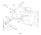
- FIG. 5comprising FIGS. 5 a - b , illustrates components of the imaging robot of FIG. 2 that has been instrumented with proximity sensors in accordance with my invention.
- FIG. 6is an alternate embodiment of a general utility robot having an enveloping intrusion detection zone of varying depth.
- FIG. 7is a mechanical representation of a simple robot illustrating pertinent parameters for sensor placement.
- FIG. 8illustrates typical fields-of-view of known proximity sensors, including CCD camera, capacitive sensor and infra-red (“IR”).
- CCD cameraCCD camera
- capacitive sensorCCD sensor
- infra-redIR
- FIG. 9comprising FIGS. 9 a - i , illustrates sensor placement selected to develop the enveloping volume on selected forms of links.
- a method and system for improved robot safety and collision avoidancewhich allows for intended contact between robot components and specific, identifiable objects in the environment of a robot with which contact is intended is provided.
- FIG. 1is a perspective view illustrating, at a high-level, the pieces of equipment in a robotic proton therapy treatment room 100 .
- a patient 102is lying down on a couch 104 of a patient positioning system 106 .
- an inclined beam proton delivery system 108is adapted to deliver beams at a selected angle, e.g., 30 degrees off the vertical.
- the proton delivery system 108includes a nozzle 110 .
- the nozzle 110includes an extendable component referred to as a snout that may include a collimator and a compensator for focusing the proton beam so as to conform the proton beam to the shape of a targeted volume of interest.
- a fieldis delivery of treatment from one beam of radiation at a particular configuration.
- a critical aspect of radiation therapyis accurate and precise placement of the patient 102 with respect to the radiation delivery system 108 .
- the patient positioning system 106may position the patient in six degrees of freedom: translation along the x, y, and z axes, roll, pitch and yaw. To orient the patient 102 with respect to the radiation delivery system 108 , all equipment is first modeled with respect to the treatment room coordinate system.
- FIG. 2is a perspective view of a 2D imaging system 112 ′ that may be used to image a patient 102 (for structural clarity only the workcell 100 ′ is shown) in conjunction with a fixed horizontal beam proton treatment system 108 ′.
- the imaging system 112 ′comprises a robotic device having a C-arm 114 ′ that may be moved relative to the patient 102 to permit imaging the patient 102 using a robot 106 ′ to create a 3D image of the patient 102 as a composite of a large set of 2D images taken from a large range of angles and from many different vantage points along the length of the patient 102 .
- control system 116adapted to control at least the primary component equipment systems used in a treatment room 100 - 100 ′, e.g., the positioning system 106 , the radiation system 108 - 108 ′, and the imaging system 112 - 112 ′.
- control system 116may comprise a controller 118 , typically a server-grade computer unit or the like, adapted to operate in response to operator commands provided via an input unit 120 , typically a combination of key entry and pointer devices, and to provide operator output via an output unit 122 , typically at least one high-resolution, color display monitor.
- control system 116is generally adapted to fulfill operator commands by executing one or more selected application software programs stored on a store 124 , typically a high-capacity, high-speed disk storage unit.
- store 124it is known to employ the store 124 to store, at least temporarily, data collected from the several component systems during operation for operator review, either in real-time or off-line.
- my inventionemploys training mechanisms, either off-line or on-line or both, to develop a model of the ideal output of each sensor that is used to detect object presence, and then, during operation, compares the modeled output with the actual, real-time sensor value.
- the type of sensor modeling requireddepends on the type of sensor, whether the application is pre-programmed or whether the application is autonomous.
- operational optionsinclude, inter alia, selectively slowing or stopping robot motion (if motion is towards the intrusion), or continuing robot motion (if motion is away from intrusion).
- the robot imaging system 112can be operated in accordance with the flow diagram of FIG. 4 .
- a training phasecomprising those steps above dashed line 126
- a plurality of sensorsare attached at selected locations (to be discussed further below) on the robot 106 .
- a model of the robot 106is then developed to determine the expected set of sensor values during all planned operations of a selected robot application software program (step 130 ).
- controller 118executes the selected robot application program (step 132 ).
- the imaging system 112is actively monitoring for intrusions (to be discussed further below) (step 134 ). So long as no intrusion is detected, execution of the application program proceeds normally; upon intrusion detection, however, an interrupt is triggered (step 136 ) to redirect the application program to an intrusion exception handling routine.
- the intrusion exception handling routinemay be adapted to selectively modify the normal behavior of the robot application program, including, e.g., slowing, stopping or reversing the current robot motion. Of course, other corrective actions may be initiated when actual sensory signals do not correlate to expected sensory signals, including, inter alia, alerting the operator(s), shutting down or otherwise rendering harmless other system components, or, in some cases, immediately shutting down the entire system.
- FIG. 5 aa representative link 138 a of a robot manipulator arm 106 ′ instrumented with a number of proximity sensors 140 .
- link 138 a of the robot 106 ′is instrumented such that the combined set of sensors 140 creates an intrusion detection zone 142 completely surrounding that link 138 a .
- the number and placement of these sensors 140is determined through 3D geometric analysis of their volumetric range, any physical mounting constraints, and the shape of the link 138 a being instrumented.
- the depth of the intrusion detection zone 140will vary from sensor to sensor, generally as a function of the stopping distance of the robot in the direction of motion of the respective link 138 a or joint 144 a - c .
- Ihave instrumented a known industrial robot manipulator 106 ′′ (sensors not shown) so as to implement a variable depth intrusion detection zone 142 ′.
- the two primary categories (extremes) of applicationare: structured or fully pre-programmed; and unstructured or autonomous.
- structured applicationsat the design time of a robot application, the robot 106 , its workcell 100 , and the application program logic are all fully specified. If an object is non-stationary, such as another robot, human, etc., then the motions each go through are also specified. This way, a human operator that is going to work in proximity to a robot 106 will have a specific motion profile that they are expected to follow.
- a time based map of the status of each proximity sensor 140is developed during the training step 130 . This map basically identifies the valid values of each sensor with respect to time and to the various operating states of the application.
- a real-time computational modelmay be employed to compute what the valid values of each sensor 140 should be, based on the anticipated state of the system 116 .
- this modelgeometrically defines the location of each sensor 140 , and updates its position based on actual position of the linkage or component on which the sensor 140 is mounted.
- the position of each sensormay be computed as a function of the Cartesian position of the mobile robot and a 3D transformation offset that defines where the sensor is mounted relative to the robot origin.
- the location of each sensormay be computed based on forward position analysis of the articulated robot arm or manipulator.
- appropriate corrective actionmay be initiated.
- the appropriate actionwill depend, at least in part, on the rate of closure of the endangered robot component and the unexpected intruding object.
- Known techniques for computing relative distance and rate of change of that distanceare disclosed in detail, e.g., in Spencer, et al., “Collision Avoidance Techniques for Tele-Operated and Autonomous Manipulators in Overlapping Workspaces”, 2007 [http://www.robotics.utexas.edu/rrg/docs/pubs/publications/ICRA08-CollisionAvoidance.pdf]; incorporated herein in its entirety by reference.
- each of the illustrated linksare referred to herein by their respective link lengths, i.e., L 1 and L 2 .
- the position of joint J 1 relative to the base of the robot 106 ′′′is defined by the angle ⁇ 1
- the position of joint J 2is defined relative to link L 1 and is equal to the angle ⁇ 2 .
- a first proximity sensor, S 1is mounted on link L 1 at a distance of l 1 from the rotational axis of joint J 1
- a second proximity sensor, S 2is mounted on link L 2 at a distance of l 2 from the rotational axis of joint J 2 .
- the position, (x, y), of each proximity sensor in Cartesian spacemay be developed as follows:
- the forward position solutiona known robot kinematics computation generally referred to as the forward position solution. This formulation may be easily extended to robots having more complex 3D geometry, and are thus not constrained to motion in 2D space.
- proximity sensorsmay be best illustrated by a set of examples.
- FOVfield-of-view
- shape of that FOVcan vary for different sensor types, as shown by way of example in FIG. 8 .
- sensorsdevelop further, they may be capable of not only detecting objects in their range, but also identifying the coordinates of the intrusion.
- Case 1A rectangular link with all angles between different faces of the link being 90° as shown in FIG. 9 a .
- wsqrt(2)*d*tan( ⁇ /2).
- Iwill assume that each sensor will detect an intrusion at distance d and w ⁇ w area. Assuming the length of the face of the illustrated robot link is l r and width is w r the maximum distance between any two sensors can be d.
- Case 2A rectangular link where the angle between any two faces may not be 90° as shown in FIG. 9 d .
- FIG. 9 eillustrates a side view of one surface of this link having an angle, S angle , greater than 90° between two adjacent, contiguous faces.
- S angledecreases, e.g., as a result of a joint rotation, any two sensors that are mounted at the edge interface between the two faces will tend to move away from each other, requiring that additional sensors (indicated by arrows as shown in FIG. 9 f ) be placed along the joint to maintain full coverage.
- Case 3Cylindrical link.
- the placement along the length of the cylinderwill be similar to that along the length of a face of a rectangular link; the placement along the circumference of the cylinder requires a different formulation.
- Shown in FIG. 9 his the cross section of a cylinder of radius r with a representative placement of proximity sensors around it.
- the proximity sensorsare placed regularly around the circumference of the cylinder at an angle, ⁇ , with respect to each other.
- Case 4General geometric link. On an arbitrary shaped robot link having an irregular curvilinear cross-section as shown in FIG. 9 i , I have positioned proximity sensors on an especially problematic portion thereof so as to achieve full coverage.
- the known mathematical formulations for rectangular and cylindrical linkscan be extended to the generic shaped link, and can be related both to the curvature of the cross-section and to the curvature orthogonal to the direction of the cross-section.
- known computer graphics or ray tracing techniquescan be used to iteratively place the sensors on the surface, and then to verify that full coverage is achieved.
- model training and operational sensingare correlated to detect real-time deviations from expected behavior.
- my inventionallows the system to selectively accept intrusions which can be anticipated during normal operation while triggering on unexpected intrusions.
Landscapes
- Engineering & Computer Science (AREA)
- Robotics (AREA)
- Mechanical Engineering (AREA)
- Manipulator (AREA)
Abstract
Description
x1=(l1*cos(θ1));
y1=(l1*sin(θ1)); and
x2=(L1*cos(θ1)+l2*cos(θ1+θ2));
y2=(L1*sin(θ1)+l2*sin(θ1+θ2)).
As the
nl>lr/(2*w).
Similarly, if nwis the number of sensors placed along the width of the robot link, then:
nw>wr/(2*w).
The same method of sensor placement, when applied to each face of the rectangular link, will develop an intrusion detection envelope of depth d surrounding the link.
No. of Edge Sensors>=(180−ø−Sangle)/ø
α=2*arctan((d*tan(θ/2))/(d+r)).
Claims (17)
Priority Applications (1)
| Application Number | Priority Date | Filing Date | Title |
|---|---|---|---|
| US13/188,602US8855812B2 (en) | 2010-07-23 | 2011-07-22 | System and method for robot safety and collision avoidance |
Applications Claiming Priority (2)
| Application Number | Priority Date | Filing Date | Title |
|---|---|---|---|
| US36700910P | 2010-07-23 | 2010-07-23 | |
| US13/188,602US8855812B2 (en) | 2010-07-23 | 2011-07-22 | System and method for robot safety and collision avoidance |
Publications (2)
| Publication Number | Publication Date |
|---|---|
| US20120022689A1 US20120022689A1 (en) | 2012-01-26 |
| US8855812B2true US8855812B2 (en) | 2014-10-07 |
Family
ID=45494251
Family Applications (1)
| Application Number | Title | Priority Date | Filing Date |
|---|---|---|---|
| US13/188,602Expired - Fee RelatedUS8855812B2 (en) | 2010-07-23 | 2011-07-22 | System and method for robot safety and collision avoidance |
Country Status (1)
| Country | Link |
|---|---|
| US (1) | US8855812B2 (en) |
Cited By (22)
| Publication number | Priority date | Publication date | Assignee | Title |
|---|---|---|---|---|
| WO2016122840A1 (en)* | 2015-01-26 | 2016-08-04 | Duke University | Specialized robot motion planning hardware and methods of making and using same |
| US9744668B1 (en) | 2015-08-21 | 2017-08-29 | X Development Llc | Spatiotemporal robot reservation systems and method |
| US10335952B2 (en) | 2017-01-18 | 2019-07-02 | International Business Machines Corporation | Monitoring and controlling the movement of mobile robots |
| US10500729B2 (en) | 2016-05-09 | 2019-12-10 | Opiflex Automation AB | Fenceless industrial robot system |
| US10545480B2 (en) | 2016-11-07 | 2020-01-28 | Lincoln Global, Inc. | System and method for manufacturing and control thereof |
| US10549116B2 (en) | 2015-03-05 | 2020-02-04 | The Regents Of The University Of California | Radiotherapy utilizing the entire 4PI solid angle |
| US11235465B2 (en) | 2018-02-06 | 2022-02-01 | Realtime Robotics, Inc. | Motion planning of a robot storing a discretized environment on one or more processors and improved operation of same |
| US11292456B2 (en) | 2018-01-12 | 2022-04-05 | Duke University | Apparatus, method and article to facilitate motion planning of an autonomous vehicle in an environment having dynamic objects |
| US11398003B2 (en)* | 2019-05-31 | 2022-07-26 | Fanuc Corporation | Machine learning apparatus, robot system, and machine learning method of learning state of cable |
| US11429105B2 (en) | 2016-06-10 | 2022-08-30 | Duke University | Motion planning for autonomous vehicles and reconfigurable motion planning processors |
| US11471702B2 (en)* | 2016-12-23 | 2022-10-18 | Koninklijke Philips N.V. | Ray tracing for a detection and avoidance of collisions between radiotherapy devices and patient |
| US11623346B2 (en) | 2020-01-22 | 2023-04-11 | Realtime Robotics, Inc. | Configuration of robots in multi-robot operational environment |
| US11634126B2 (en) | 2019-06-03 | 2023-04-25 | Realtime Robotics, Inc. | Apparatus, methods and articles to facilitate motion planning in environments having dynamic obstacles |
| US11648673B2 (en) | 2020-05-26 | 2023-05-16 | Intrinsic Innovation Llc | Automated safety procedures for human intervention in robot systems |
| US11673265B2 (en) | 2019-08-23 | 2023-06-13 | Realtime Robotics, Inc. | Motion planning for robots to optimize velocity while maintaining limits on acceleration and jerk |
| US11676845B2 (en) | 2020-06-30 | 2023-06-13 | Brooks Automation Us, Llc | Automated teach apparatus for robotic systems and method therefor |
| US11738457B2 (en) | 2018-03-21 | 2023-08-29 | Realtime Robotics, Inc. | Motion planning of a robot for various environments and tasks and improved operation of same |
| US12017364B2 (en) | 2019-04-17 | 2024-06-25 | Realtime Robotics, Inc. | Motion planning graph generation user interface, systems, methods and articles |
| US12194639B2 (en) | 2020-03-18 | 2025-01-14 | Realtime Robotics, Inc. | Digital representations of robot operational environment, useful in motion planning for robots |
| US12204336B2 (en) | 2018-12-04 | 2025-01-21 | Duke University | Apparatus, method and article to facilitate motion planning in an environment having dynamic objects |
| US12330310B2 (en) | 2018-08-23 | 2025-06-17 | Realtime Robotics, Inc. | Collision detection useful in motion planning for robotics |
| US12358140B2 (en) | 2019-06-24 | 2025-07-15 | Realtime Robotics, Inc. | Motion planning for multiple robots in shared workspace |
Families Citing this family (28)
| Publication number | Priority date | Publication date | Assignee | Title |
|---|---|---|---|---|
| JP5017379B2 (en)* | 2008-01-22 | 2012-09-05 | パナソニック株式会社 | Robot arm |
| US8855812B2 (en)* | 2010-07-23 | 2014-10-07 | Chetan Kapoor | System and method for robot safety and collision avoidance |
| JPWO2013175554A1 (en)* | 2012-05-21 | 2016-01-12 | 株式会社安川電機 | Robot and robot system |
| JP5924134B2 (en)* | 2012-05-30 | 2016-05-25 | セイコーエプソン株式会社 | Intrusion detection device, robot system, intrusion detection method, and intrusion detection program |
| EP2890529A2 (en) | 2012-08-31 | 2015-07-08 | Rethink Robotics Inc. | Systems and methods for safe robot operation |
| CN105188590B (en) | 2012-12-10 | 2019-04-26 | 直观外科手术操作公司 | Collision avoidance during controlled movement of an image capture device and an actuatable device movable arm |
| JP6123307B2 (en)* | 2013-01-23 | 2017-05-10 | 株式会社デンソーウェーブ | Surveillance system and method for monitoring the intrusion of an object around a robot |
| TWI547355B (en)* | 2013-11-11 | 2016-09-01 | 財團法人工業技術研究院 | Safety monitoring system of human-machine symbiosis and method using the same |
| WO2016189495A1 (en) | 2015-05-27 | 2016-12-01 | Van Dyke, Marc | Alerting predicted accidents between driverless cars |
| US10031522B2 (en) | 2015-05-27 | 2018-07-24 | Dov Moran | Alerting predicted accidents between driverless cars |
| US10198706B2 (en)* | 2015-07-31 | 2019-02-05 | Locus Robotics Corp. | Operator identification and performance tracking |
| US10213923B2 (en)* | 2015-09-09 | 2019-02-26 | Carbon Robotics, Inc. | Robotic arm system and object avoidance methods |
| JP6444908B2 (en)* | 2016-02-17 | 2018-12-26 | ファナック株式会社 | Robot simulation device for calculating sweep space |
| JP6733239B2 (en)* | 2016-03-18 | 2020-07-29 | セイコーエプソン株式会社 | Controller and robot system |
| US11000953B2 (en)* | 2016-08-17 | 2021-05-11 | Locus Robotics Corp. | Robot gamification for improvement of operator performance |
| US12103170B2 (en)* | 2017-01-13 | 2024-10-01 | Clara Vu | Dynamic, interactive signaling of safety-related conditions in a monitored environment |
| US11518051B2 (en)* | 2017-02-07 | 2022-12-06 | Veo Robotics, Inc. | Dynamic, interactive signaling of safety-related conditions in a monitored environment |
| JP6479264B2 (en)* | 2017-01-13 | 2019-03-06 | 三菱電機株式会社 | Collaborative robot system and control method thereof |
| US10882185B2 (en) | 2017-02-07 | 2021-01-05 | Veo Robotics, Inc. | Dynamically determining workspace safe zones with speed and separation monitoring |
| US11820025B2 (en) | 2017-02-07 | 2023-11-21 | Veo Robotics, Inc. | Safe motion planning for machinery operation |
| US11541543B2 (en)* | 2017-02-07 | 2023-01-03 | Veo Robotics, Inc. | Dynamic, interactive signaling of safety-related conditions in a monitored environment |
| EP3427904B1 (en)* | 2017-07-13 | 2020-06-10 | Siemens Aktiengesellschaft | Assembly with a manipulator and a limiting device for limiting the working space |
| EP3488984A1 (en)* | 2017-11-24 | 2019-05-29 | SCM Group S.p.A. | Machine for working workpieces, made of wood and the like, provided with a system for detecting the presence of an operator, and operation method thereof |
| US12049014B2 (en)* | 2018-02-06 | 2024-07-30 | Veo Robotics, Inc. | Workplace monitoring and semantic entity identification for safe machine operation |
| US12097625B2 (en)* | 2018-02-06 | 2024-09-24 | Veo Robotics, Inc. | Robot end-effector sensing and identification |
| ES2971025T3 (en) | 2018-05-18 | 2024-06-03 | Universal Robots As | Robot joint comprising a brake assembly |
| US11597104B2 (en)* | 2019-07-31 | 2023-03-07 | X Development Llc | Mobile robot sensor configuration |
| JPWO2023037456A1 (en)* | 2021-09-08 | 2023-03-16 |
Citations (13)
| Publication number | Priority date | Publication date | Assignee | Title |
|---|---|---|---|---|
| US4706120A (en)* | 1985-08-30 | 1987-11-10 | Texas Instruments Incorporated | Modular, vision system for automation of inspection and process control |
| US6734581B1 (en)* | 1998-10-28 | 2004-05-11 | Eigenpoint Company | Programmable emergency-stop circuit with testing |
| US20050251291A1 (en)* | 2002-08-21 | 2005-11-10 | Neal Solomon | System, method and apparatus for organizing groups of self-configurable mobile robotic agents in a multi-robotic system |
| US20060133573A1 (en)* | 2004-03-31 | 2006-06-22 | Phillip Wong | Radiosurgery x-ray system with collision avoidance subsystem |
| US7072740B2 (en)* | 2002-12-16 | 2006-07-04 | Sony Corporation | Legged mobile robot |
| US20070199108A1 (en)* | 2005-09-30 | 2007-08-23 | Colin Angle | Companion robot for personal interaction |
| US20080042076A1 (en)* | 2003-08-12 | 2008-02-21 | Loma Linda University Medical Center | Modular patient support system |
| US20090234499A1 (en)* | 2008-03-13 | 2009-09-17 | Battelle Energy Alliance, Llc | System and method for seamless task-directed autonomy for robots |
| US20100152899A1 (en)* | 2008-11-17 | 2010-06-17 | Energid Technologies, Inc. | Systems and methods of coordination control for robot manipulation |
| US20100286797A1 (en)* | 2009-05-11 | 2010-11-11 | Gm Global Technology Operations, Inc. | Method and system for testing safety automation logic of a manufacturing cell |
| US20120022689A1 (en)* | 2010-07-23 | 2012-01-26 | Agile Planet, Inc. | System and Method for Robot Safety and Collision Avoidance |
| US20120185094A1 (en)* | 2010-05-20 | 2012-07-19 | Irobot Corporation | Mobile Human Interface Robot |
| US8639644B1 (en)* | 2011-05-06 | 2014-01-28 | Google Inc. | Shared robot knowledge base for use with cloud computing system |
- 2011
- 2011-07-22USUS13/188,602patent/US8855812B2/ennot_activeExpired - Fee Related
Patent Citations (19)
| Publication number | Priority date | Publication date | Assignee | Title |
|---|---|---|---|---|
| US4706120A (en)* | 1985-08-30 | 1987-11-10 | Texas Instruments Incorporated | Modular, vision system for automation of inspection and process control |
| US6734581B1 (en)* | 1998-10-28 | 2004-05-11 | Eigenpoint Company | Programmable emergency-stop circuit with testing |
| US7343222B2 (en)* | 2002-08-21 | 2008-03-11 | Solomon Research Llc | System, method and apparatus for organizing groups of self-configurable mobile robotic agents in a multi-robotic system |
| US20050251291A1 (en)* | 2002-08-21 | 2005-11-10 | Neal Solomon | System, method and apparatus for organizing groups of self-configurable mobile robotic agents in a multi-robotic system |
| US8112176B2 (en)* | 2002-08-21 | 2012-02-07 | Neal Solomon | System for self-organizing mobile robotic collectives |
| US20100286824A1 (en)* | 2002-08-21 | 2010-11-11 | Neal Solomon | System for self-organizing mobile robotic collectives |
| US7072740B2 (en)* | 2002-12-16 | 2006-07-04 | Sony Corporation | Legged mobile robot |
| US20080042076A1 (en)* | 2003-08-12 | 2008-02-21 | Loma Linda University Medical Center | Modular patient support system |
| US20060133573A1 (en)* | 2004-03-31 | 2006-06-22 | Phillip Wong | Radiosurgery x-ray system with collision avoidance subsystem |
| US20090177323A1 (en)* | 2005-09-30 | 2009-07-09 | Andrew Ziegler | Companion robot for personal interaction |
| US20070199108A1 (en)* | 2005-09-30 | 2007-08-23 | Colin Angle | Companion robot for personal interaction |
| US20110172822A1 (en)* | 2005-09-30 | 2011-07-14 | Andrew Ziegler | Companion Robot for Personal Interaction |
| US20120303160A1 (en)* | 2005-09-30 | 2012-11-29 | Irobot Corporation | Companion robot for personal interaction |
| US20090234499A1 (en)* | 2008-03-13 | 2009-09-17 | Battelle Energy Alliance, Llc | System and method for seamless task-directed autonomy for robots |
| US20100152899A1 (en)* | 2008-11-17 | 2010-06-17 | Energid Technologies, Inc. | Systems and methods of coordination control for robot manipulation |
| US20100286797A1 (en)* | 2009-05-11 | 2010-11-11 | Gm Global Technology Operations, Inc. | Method and system for testing safety automation logic of a manufacturing cell |
| US20120185094A1 (en)* | 2010-05-20 | 2012-07-19 | Irobot Corporation | Mobile Human Interface Robot |
| US20120022689A1 (en)* | 2010-07-23 | 2012-01-26 | Agile Planet, Inc. | System and Method for Robot Safety and Collision Avoidance |
| US8639644B1 (en)* | 2011-05-06 | 2014-01-28 | Google Inc. | Shared robot knowledge base for use with cloud computing system |
Non-Patent Citations (1)
| Title |
|---|
| Spencer, et al., "Collision Avoidance Techniques for Tele-Operated and Autonomous Manipulators in Overlapping Workspaces", 2007 [http://www.robotics.utexas.edu/rrg/docs/ pubs/publications/ICRA08-CollisionAvoidance.pdf]. |
Cited By (31)
| Publication number | Priority date | Publication date | Assignee | Title |
|---|---|---|---|---|
| WO2016122840A1 (en)* | 2015-01-26 | 2016-08-04 | Duke University | Specialized robot motion planning hardware and methods of making and using same |
| US10723024B2 (en) | 2015-01-26 | 2020-07-28 | Duke University | Specialized robot motion planning hardware and methods of making and using same |
| US10549116B2 (en) | 2015-03-05 | 2020-02-04 | The Regents Of The University Of California | Radiotherapy utilizing the entire 4PI solid angle |
| US9744668B1 (en) | 2015-08-21 | 2017-08-29 | X Development Llc | Spatiotemporal robot reservation systems and method |
| US10369696B1 (en) | 2015-08-21 | 2019-08-06 | X Development Llc | Spatiotemporal robot reservation systems and method |
| US10500729B2 (en) | 2016-05-09 | 2019-12-10 | Opiflex Automation AB | Fenceless industrial robot system |
| US11429105B2 (en) | 2016-06-10 | 2022-08-30 | Duke University | Motion planning for autonomous vehicles and reconfigurable motion planning processors |
| US10545480B2 (en) | 2016-11-07 | 2020-01-28 | Lincoln Global, Inc. | System and method for manufacturing and control thereof |
| US10599127B2 (en) | 2016-11-07 | 2020-03-24 | Lincoln Global, Inc. | System and method for manufacturing and control thereof |
| US11067965B2 (en) | 2016-11-07 | 2021-07-20 | Lincoln Global, Inc. | System and method for additive manufacturing and control thereof |
| US11471702B2 (en)* | 2016-12-23 | 2022-10-18 | Koninklijke Philips N.V. | Ray tracing for a detection and avoidance of collisions between radiotherapy devices and patient |
| US10335952B2 (en) | 2017-01-18 | 2019-07-02 | International Business Machines Corporation | Monitoring and controlling the movement of mobile robots |
| US11292456B2 (en) | 2018-01-12 | 2022-04-05 | Duke University | Apparatus, method and article to facilitate motion planning of an autonomous vehicle in an environment having dynamic objects |
| US11970161B2 (en) | 2018-01-12 | 2024-04-30 | Duke University | Apparatus, method and article to facilitate motion planning of an autonomous vehicle in an environment having dynamic objects |
| US12090668B2 (en) | 2018-02-06 | 2024-09-17 | Realtime Robotics, Inc. | Motion planning of a robot storing a discretized environment on one or more processors and improved operation of same |
| US11235465B2 (en) | 2018-02-06 | 2022-02-01 | Realtime Robotics, Inc. | Motion planning of a robot storing a discretized environment on one or more processors and improved operation of same |
| US11745346B2 (en) | 2018-02-06 | 2023-09-05 | Realtime Robotics, Inc. | Motion planning of a robot storing a discretized environment on one or more processors and improved operation of same |
| US11964393B2 (en) | 2018-03-21 | 2024-04-23 | Realtime Robotics, Inc. | Motion planning of a robot for various environments and tasks and improved operation of same |
| US12083682B2 (en) | 2018-03-21 | 2024-09-10 | Realtime Robotics, Inc. | Motion planning of a robot for various environments and tasks and improved operation of same |
| US11738457B2 (en) | 2018-03-21 | 2023-08-29 | Realtime Robotics, Inc. | Motion planning of a robot for various environments and tasks and improved operation of same |
| US12330310B2 (en) | 2018-08-23 | 2025-06-17 | Realtime Robotics, Inc. | Collision detection useful in motion planning for robotics |
| US12204336B2 (en) | 2018-12-04 | 2025-01-21 | Duke University | Apparatus, method and article to facilitate motion planning in an environment having dynamic objects |
| US12017364B2 (en) | 2019-04-17 | 2024-06-25 | Realtime Robotics, Inc. | Motion planning graph generation user interface, systems, methods and articles |
| US11398003B2 (en)* | 2019-05-31 | 2022-07-26 | Fanuc Corporation | Machine learning apparatus, robot system, and machine learning method of learning state of cable |
| US11634126B2 (en) | 2019-06-03 | 2023-04-25 | Realtime Robotics, Inc. | Apparatus, methods and articles to facilitate motion planning in environments having dynamic obstacles |
| US12358140B2 (en) | 2019-06-24 | 2025-07-15 | Realtime Robotics, Inc. | Motion planning for multiple robots in shared workspace |
| US11673265B2 (en) | 2019-08-23 | 2023-06-13 | Realtime Robotics, Inc. | Motion planning for robots to optimize velocity while maintaining limits on acceleration and jerk |
| US11623346B2 (en) | 2020-01-22 | 2023-04-11 | Realtime Robotics, Inc. | Configuration of robots in multi-robot operational environment |
| US12194639B2 (en) | 2020-03-18 | 2025-01-14 | Realtime Robotics, Inc. | Digital representations of robot operational environment, useful in motion planning for robots |
| US11648673B2 (en) | 2020-05-26 | 2023-05-16 | Intrinsic Innovation Llc | Automated safety procedures for human intervention in robot systems |
| US11676845B2 (en) | 2020-06-30 | 2023-06-13 | Brooks Automation Us, Llc | Automated teach apparatus for robotic systems and method therefor |
Also Published As
| Publication number | Publication date |
|---|---|
| US20120022689A1 (en) | 2012-01-26 |
Similar Documents
| Publication | Publication Date | Title |
|---|---|---|
| US8855812B2 (en) | System and method for robot safety and collision avoidance | |
| JP7122776B2 (en) | Workspace safety monitoring and equipment control | |
| Flacco et al. | A depth space approach for evaluating distance to objects: with application to human-robot collision avoidance | |
| EP3715065B1 (en) | Controlling a robot in the presence of a moving object | |
| KR102628659B1 (en) | System and method for monitoring control points during reactive motion | |
| KR102379623B1 (en) | System and method for dynamic virtual collision objects | |
| TWI547355B (en) | Safety monitoring system of human-machine symbiosis and method using the same | |
| US8311731B2 (en) | Robots with collision avoidance functionality | |
| TW202231428A (en) | Safety systems and methods employed in robot operations | |
| US20080312771A1 (en) | Robots with Occlusion Avoidance Functionality | |
| KR101339009B1 (en) | Robot system for radiation cancer treatment | |
| KR20220002408A (en) | Methods and systems for operating robots | |
| US20220176560A1 (en) | Control system, control method, and control unit | |
| EP2023160A1 (en) | 3D room surveillance with configuration mode for determining the protection fields | |
| CN111906778A (en) | Robot safety control method and device based on multiple perceptions | |
| US20230256606A1 (en) | Robot System with Object Detecting Sensors | |
| CN111283688B (en) | Obstacle avoidance method of robot and robot equipment | |
| US12154185B2 (en) | System and method for verifying positional and spatial information using depth sensors | |
| Cabrera et al. | Cohaptics: Development of human-robot collaborative system with forearm-worn haptic display to increase safety in future factories | |
| Forlini et al. | Experimental implementation of skeleton tracking for collision avoidance in collaborative robotics | |
| US11279034B2 (en) | Position monitoring of a kinematic linkage | |
| DE102022130178A1 (en) | INTEGRITY AND SAFETY TESTING FOR ROBOTS | |
| JP3565763B2 (en) | Master arm link position detection method | |
| Hietanen et al. | Depth-sensor-projector safety model for human-robot collaboration | |
| Di Castro et al. | A real-time reconfigurable collision avoidance system for robot manipulation |
Legal Events
| Date | Code | Title | Description |
|---|---|---|---|
| AS | Assignment | Owner name:AGILE PLANET, INC., TEXAS Free format text:ASSIGNMENT OF ASSIGNORS INTEREST;ASSIGNOR:KAPOOR, CHETAN;REEL/FRAME:026633/0967 Effective date:20110721 | |
| AS | Assignment | Owner name:AGILE PLANET, INC., TEXAS Free format text:ASSIGNMENT OF ASSIGNORS INTEREST;ASSIGNOR:KAPOOR, CHETAN;REEL/FRAME:031028/0001 Effective date:20130611 | |
| AS | Assignment | Owner name:KAPOOR, CHETAN, TEXAS Free format text:CORRECTIVE ASSIGNMENT TO CORRECT THE TO CORRECT THE ASSIGNOR AND ASSIGNEE'S NAME PREVIOUSLY RECORDED ON REEL 031028 FRAME 0001. ASSIGNOR(S) HEREBY CONFIRMS THE ASSIGNMENT;ASSIGNOR:AGILE PLANET, INC.;REEL/FRAME:031035/0188 Effective date:20130611 | |
| STCF | Information on status: patent grant | Free format text:PATENTED CASE | |
| MAFP | Maintenance fee payment | Free format text:PAYMENT OF MAINTENANCE FEE, 4TH YR, SMALL ENTITY (ORIGINAL EVENT CODE: M2551) Year of fee payment:4 | |
| FEPP | Fee payment procedure | Free format text:MAINTENANCE FEE REMINDER MAILED (ORIGINAL EVENT CODE: REM.); ENTITY STATUS OF PATENT OWNER: SMALL ENTITY | |
| LAPS | Lapse for failure to pay maintenance fees | Free format text:PATENT EXPIRED FOR FAILURE TO PAY MAINTENANCE FEES (ORIGINAL EVENT CODE: EXP.); ENTITY STATUS OF PATENT OWNER: SMALL ENTITY | |
| STCH | Information on status: patent discontinuation | Free format text:PATENT EXPIRED DUE TO NONPAYMENT OF MAINTENANCE FEES UNDER 37 CFR 1.362 | |
| FP | Lapsed due to failure to pay maintenance fee | Effective date:20221007 |